tender document tender no: …engineeringprojects.com/tender/uploadfiles/3450_vol-2.pdf · of rgcb...
TRANSCRIPT
AN ISO 9001 & 14001 COMPANY
TENDER DOCUMENT
TENDER No: SRO/CON/ETS/001 DATED 09.01.2018
FOR
Tender for "Establishment of a Second Campus for RGCB Bio Innovation Research Centre at Akkulam in Thiruvananthapuram District, Kerala State Phase. I - Construction of Research Block
with Animal House, Hostel Buildings, and Allied Infrastructure Facilities- Supply of HT < cables – Pkg. – 4 A1".
VOLUME – II
Additional Purchase Conditions
& Client Documents
Additional Purchase Conditions__________________________________________________________________________Engineering Projects (India) Limited
_______________________________________________________________________________________________________ Signature of Contractor with seal 1 EPI
ADDITIONAL PURCHASE OF CONTRACT (APC)
1.0 The following Additional Purchase Conditions of Contract shall be read in conjunction with General Purchase Conditions (GPC). If there are any provisions in these Special Conditions of Contract, which are at variance with the provisions of General Purchase Conditions (GPC), the provisions in these Additional Purchase Conditions shall take precedence.
2.0 Introduction
Consortium of Architect Hafeez Contractor and M/s Iyer and Mahesh, a PMC engaged by RGCB, intends to undertake the Construction of RGCB Bio Innovation Center at Akkulam in Thiruvananthapuram District, Kerala State Phase I.
3.0 Scope of work:
The project site for the work is available.
The brief scope of work included in this tender shall include (but not limited to) for Construction of RGCB Bio Innovation Center at Akkulam in Thiruvananthapuram District, Kerala State Phase I – Construction of Research Block with Animal House, Hostel Buildings, and Allied Infrastructure Facilities- Supply of HT < cables - Pkg - 4A2" (hereinafter referred to as “Works’) as per Technical specifications, Drawings, BOQ, Instructions and Terms and conditions given in Tender Documents. Apart from above, any other services not covered above but required as per direction of EPI / RGCB are deemed to be included in the scope of work. The work is to be carried out on Item rate basis as per bill of quantities and tender conditions.
4.0 Maintenance Period The maintenance period for the work shall be twelve months after handing over to Client and any defects noticed during the period shall have to be rectified by Contractor at his cost, failing which the action taken for rectification by EPIL RGCB shall be final.
5.0 Order of Precedence
i) NIT ii) APC iii) BOQ, Technical Specifications and Drawings iv) EPI GPC
6.0 Disqualification
The tenderers may note that they are liable to be disqualified and not considered for the opening of Price Bid if;
a) Representation in the forms, statements and attachments submitted in the pre-qualification document are proved to be incorrect, false and misleading.
b) They have record of poor performance during the past 10 (ten) years such as abandoning the work, rescinding of contract for which the reasons are attributable to the non-performance of the contractor, inordinate delay in completion, consistent history of litigation / arbitration awarded against the contractor or any of its constituents or financial failures due to bankruptcy etc. in their ongoing / past projects.
c) They have submitted incompletely filled in formats without attaching certified supporting documents and credentials to establish their eligibility to participate in the Tender.
d) If the tenderers attempt to influence any member of the selection committee. EPI reserves its right to take appropriate action including disqualification of tenderer(s) as may be deemed fit and proper by EPI at any time without giving any notice to the contractor in this
Additional Purchase Conditions__________________________________________________________________________Engineering Projects (India) Limited
_______________________________________________________________________________________________________ Signature of Contractor with seal 2 EPI
regard. The decision of EPI in the matter of disqualification shall be final and binding on the Tenderers.
7.0 SPECIFICATIONS
i) All works in general are to be carried out in accordance with the CPWD Specifications for works 2009 vol. I and vol. II, which are detailed in technical specification separately attached with this tender.
ii) This contract shall be governed by the Indian Laws for the time being in force. The contract is confidential and must be strictly confined to the purposes of the contract.
iii) The contractor shall provide everything necessary for the proper execution of the works according to the intent and meaning of the specifications and drawings taken together whether the same may or may not be particularly shown or described therein provided that the same can be reasonably be inferred there from and if the contractor finds any discrepancy in the specifications and drawings and between the drawings, he shall immediately and in writing refer the same to the employer who shall decide which is to be followed.
vi) The work order/LOI will be issued by EPI and handing over of the site and date of commencement of the contract shall be within 10 (ten) days of issue of such letter.
8.0 TAXES AND DUTIES: Price Quoted by the bidders should be exclusive of GST.GST shall be reimbursed to the bidder only on proof of submission of documentary evidence and ITC appeared in the name of EPI.
i) The contractor / supplier will consider the all other taxes and duties (excluding GST) in the price.
9.0 Inspection, Checking, Testing and other special conditions:
a. The Clause No.6 of GPC shall be added as” The materials shall be tested as mentioned in the Technical Specification and QAP”.
b. In any case, the stores must be strictly in accordance with the purchase order failing which the BUYER / EPI shall have the right to reject goods and hold the supplier liable for non-performance of contract.
c. Bidder / supplier must ensure delivery of fresh and good materials failing which the BUYER / EPI shall have the right to reject goods and hold the supplier liable for non-performance of contract. Besides the bidder / supplier shall render his service / supervision during erection, testing and commissioning of the materials.
d. The following shall stand added to clause no 9 of GPC:
e. Security deposit can be submitted in the form of Bank guarantee from a scheduled bank also and shall be valid upto the warranty period as per clause 17 of GPC.
f. Spare Parts: The Clause No.20 of GPC stands deleted.
g. Drawings: The supplier shall furnish GA drawing, BOM, Single line Diagram of the panels sheet within 7 days of acceptance of his offer i.e. issuance of purchase order by EPI for approval/ getting manufacturing clearance from EPI along with Quality Assurance Plan (QAP) mentioning the tests and checks to be carried out at the manufacturer’s place prior to dispatch .
Additional Purchase Conditions__________________________________________________________________________Engineering Projects (India) Limited
_______________________________________________________________________________________________________ Signature of Contractor with seal 3 EPI
h. Quantity Variation: i. The rates quoted by the bidder shall remain firm up to a quantity variation of plus or minus
20% to the quantities mentioned in the Price Bid.
j. EMD of the unsuccessful bidders shall be returned after 30 days of the opening of the Price Bid.
k. Check List for Evaluation & Selection of Suppliers / Vendors needn’t be filled by approved manufacturers.
10.0 PERFORMANCE GUARANTEE: In the event of award of “Works”, PARTY shall submit to EPI, Crossed Demand Draft / Bank Guarantee from a Nationalized Bank / Scheduled Bank towards performance guarantee @ 5% (Five Percent Only) of the contract value of the accepted tender within 15 days from the date of LOI shall be valid up to the stipulated date of completion plus 60 days beyond failing which EPI at his discretion may revoke the LOI & forfeit the EMD furnished along with tender. In case the time for completion of work gets enlarged, the contractor shall get the validity of Performance Guarantee extended to cover such enlarged time for completion of work. After recording of the completion certificate for the work by the competent authority, the performance guarantee shall be returned to the contractor, without any interest. However, in case of contracts involving maintenance of building and services/any other work after construction of same building and services/other work, then 50% of Performance Guarantee shall be retained as Security Deposit. The same shall be returned year wise proportionately.
11.0 SECURITY DEPOSIT (RETENTION MONEY) -
A sum at the rate of 2.5% of the gross amount of each running and final bill will be deducted. Such deductions will be made and held by EPI by way of Security Deposit.
Security Deposit of material shall be released within 30 days after expiry of the warranty period of as per Clause 17 of GPC and on satisfactory completion of supervision during erection, testing and commissioning of the materials,
12.0 Payment Terms and Conditions:
The Clause No.4 and sub clauses 4.1, 4.2 of GPC shall be replaced as under: Unless otherwise agreed upon between the parties, payment for delivery of the stores will be made on submission of bills in accordance with instruction given in the purchase order by RTGS in accordance with the following procedure.
1) All other items having Supply only or installation, testing and commissioning only Supply or Installation of item - 90% Testing & Commissioning / completion of scope of work -10%
(Deduction towards Security Deposit/Retention Money is applicable as per contract)
The Contractor/Supplier shall become entitled for payment of RA bills /Final bill etc., after receipt of corresponding payment(s) from the Client/ Owner.
Contractor should submit the details as mentioned below: i) Name of the Bank and branch with address ii) Account number and type of the account: iii) Name of the account holder iv) IFSC Code: v) GST Number and details
Additional Purchase Conditions__________________________________________________________________________Engineering Projects (India) Limited
_______________________________________________________________________________________________________ Signature of Contractor with seal 4 EPI
The rates quoted by the bidder shall be inclusive of all taxes (excluding GST), freight, packing & forwarding, excise duties and other charges as applicable on FOR site delivery basis including unloading of the materials at site.
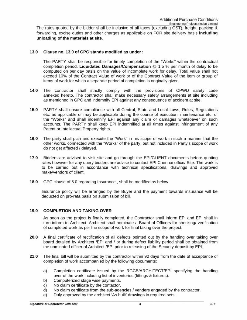
13.0 Clause no. 13.0 of GPC stands modified as under :
The PARTY shall be responsible for timely completion of the “Works” within the contractual completion period. Liquidated Damages/Compensation @ 1.5 % per month of delay to be computed on per day basis on the value of incomplete work for delay. Total value shall not exceed 10% of the Contract Value of work or of the Contract Value of the item or group of items of work for which a separate period of completion is originally given.
14.0 The contractor shall strictly comply with the provisions of CPWD safety code annexed hereto. The contractor shall make necessary safety arrangements at site including as mentioned in GPC and indemnify EPI against any consequence of accident at site.
15.0 PARTY shall ensure compliance with all Central, State and Local Laws, Rules, Regulations etc. as applicable or may be applicable during the course of execution, maintenance etc. of the “Works” and shall indemnify EPI against any claim or damages whatsoever on such accounts. The PARTY shall keep EPI indemnified at all times against infringement of any Patent or Intellectual Property rights.
16.0 The party shall plan and execute the “Work” in his scope of work in such a manner that the other works, connected with the “Works” of the party, but not included in Party’s scope of work do not get affected / delayed.
17.0 Bidders are advised to visit site and go through the EPI/CLIENT documents before quoting rates however for any query bidders are advise to contact EPI Chennai office/ Site. The work is to be carried out in accordance with technical specifications, drawings and approved make/vendors of client.
18.0 GPC clause of 5.0 regarding Insurance , shall be modified as below
Insurance policy will be arranged by the Buyer and the payment towards insurance will be deducted on pro-rata basis on submission of bill.
19.0 COMPLETION AND TAKING OVER As soon as the project is finally completed, the Contractor shall inform EPI and EPI shall in turn inform to Architect. Architect shall nominate a Board of Officers for checking/ verification of completed work as per the scope of work for final taking over the project.
20.0 A final certificate of rectification of all defects pointed out by the handing over taking over board detailed by Architect /EPI and / or during defect liability period shall be obtained from the nominated officer of Architect /EPI prior to releasing of the Security deposit by EPI.
21.0 The final bill will be submitted by the contractor within 90 days from the date of acceptance of completion of work accompanied by the following documents:
a) Completion certificate issued by the RGCB/ARCHITECT/EPI specifying the handing over of the work including list of inventories (fittings & fixtures).
b) Computerized stage wise payments. c) No claim certificate by the contactor. d) No claim certificate from the sub-agencies / venders engaged by the contractor. e) Duly approved by the architect ‘As built’ drawings in required sets.
Additional Purchase Conditions__________________________________________________________________________Engineering Projects (India) Limited
_______________________________________________________________________________________________________ Signature of Contractor with seal 5 EPI
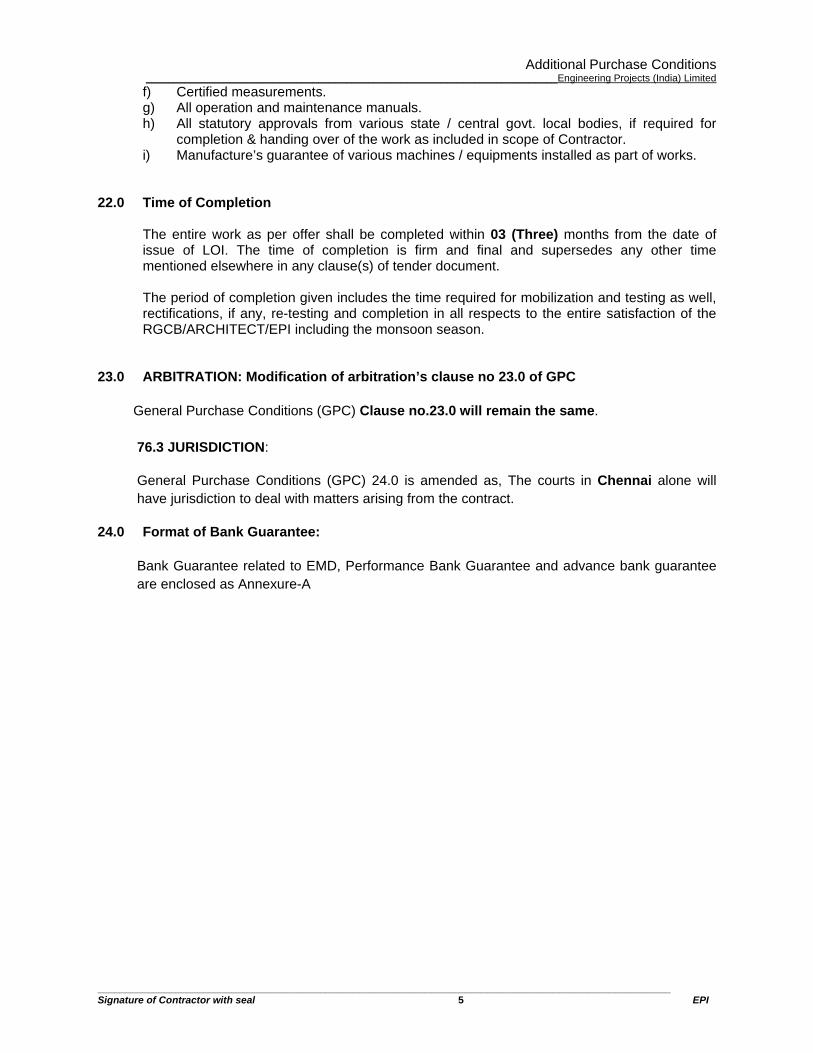
f) Certified measurements. g) All operation and maintenance manuals. h) All statutory approvals from various state / central govt. local bodies, if required for
completion & handing over of the work as included in scope of Contractor. i) Manufacture’s guarantee of various machines / equipments installed as part of works.
22.0 Time of Completion
The entire work as per offer shall be completed within 03 (Three) months from the date of issue of LOI. The time of completion is firm and final and supersedes any other time mentioned elsewhere in any clause(s) of tender document.
The period of completion given includes the time required for mobilization and testing as well, rectifications, if any, re-testing and completion in all respects to the entire satisfaction of the RGCB/ARCHITECT/EPI including the monsoon season.
23.0 ARBITRATION: Modification of arbitration’s clause no 23.0 of GPC
General Purchase Conditions (GPC) Clause no.23.0 will remain the same.
76.3 JURISDICTION:
General Purchase Conditions (GPC) 24.0 is amended as, The courts in Chennai alone will have jurisdiction to deal with matters arising from the contract.
24.0 Format of Bank Guarantee:
Bank Guarantee related to EMD, Performance Bank Guarantee and advance bank guarantee are enclosed as Annexure-A
Rajiv Gandhi Centre for Bio Technology 1
RAJIV GANDHI CENTRE FOR BIO TECHNOLOGY POOJAPPURA, THIRUVANANTHAPURAM
(RGCB)
COMPOSITE TENDER
Establishment of RGCB Bio Innovation Center
at Akkulam in Thiruvananthapuram District, Kerala State
Phase. I – Construction of Research Block with Animal Research Facility,
Hostel Buildings, Civil & Related MEP works including site development
and connected Infrastructure (Composite Contract)
TENDER DOCUMENT
VOLUME – II
TECHNICAL SPECIFICATIONS
Rajiv Gandhi Centre for Bio Technology 2
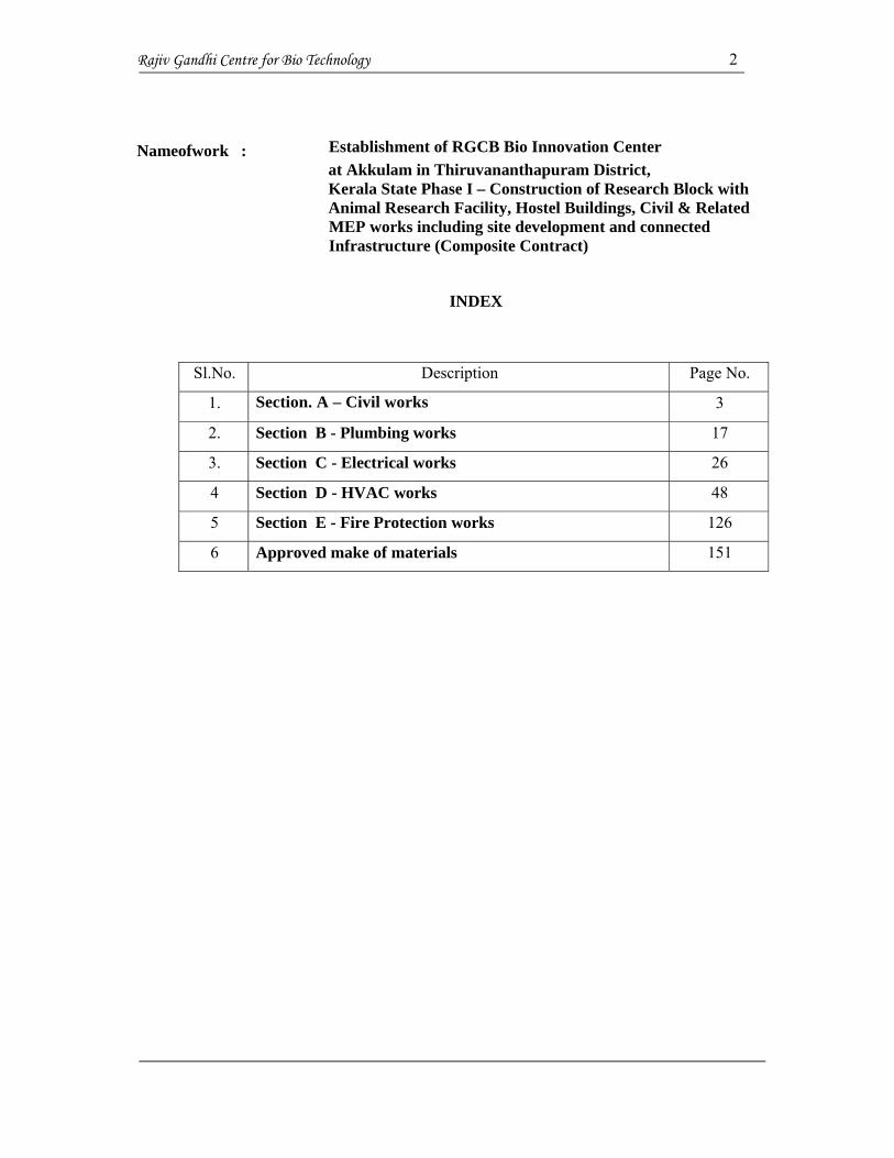
Nameofwork : Establishment of RGCB Bio Innovation Center at Akkulam in Thiruvananthapuram District, Kerala State Phase I – Construction of Research Block with Animal Research Facility, Hostel Buildings, Civil & Related MEP works including site development and connected Infrastructure (Composite Contract)
INDEX
Sl.No. Description Page No.
1. Section. A – Civil works 3
2. Section B - Plumbing works 17
3. Section C - Electrical works 26
4 Section D - HVAC works 48
5 Section E - Fire Protection works 126
6 Approved make of materials 151

Rajiv Gandhi Centre for Bio Technology 3
SECTION. C – ELECTRICAL WORKS Technical Specification for Non DSR items
I. SPECIFICATION AND TECHNICAL PARTICULARS FOR UPS
1.1 Scope
The present special contract specifications constitute a call for best offers for the supply of
Uninterruptible Power System(s) (hereinafter referred to as UPS) rated at 3X80 kVA in parallel
redundant configuration, featuring Maintenance Free Sealed Lead Acid batteries housed in one
or more external racks/cubicles and providing a minimum autonomy of 15 minutes.
The present specifications contain minimum requirements. All offers must be completed strictly
in accordance therewith, either by confirming data or by filling in the spaces provided, where
requirements are not met. Any deviations or exceptions to the minimum requirements must
appear in the offer. Where no exceptions are shown, the requirements of the present
specifications will be considered as accepted.
A redundant system can be created by connecting 3 complete units of the same type in parallel.
This parallel redundant configuration shall have redundant batteries and a decentralized bypass.
The load is shared amongst the units connected in parallel. Units with a central control module
and/or central static bypass are not accepted
2.0 RELEVANT REFERENCE STANDARDS
The choice of materials and components, engineering developments and the construction of the
equipment must comply with current directives and standards.
The UPS will have a CE mark as specified by Directives 73/23, 93/68, 89/336, 92/31 and 93/68.
The UPS will be designed and produced according to the following specifications:
IEC/EN 62040-1-1 "General and safety requirements for UPS used in operator
access areas."
EN 62040-2 “Electromagnetic compatibility (EMC) requirements”
IEC/EN 62040-3 “Performance requirements and test methods”
3.0 DESCRIPTION OF SUPPLY
The purpose of the enclosed specification is to define minimum design, construction and testing
criteria relating to the supply of Uninterruptible Power Systems (UPS).
Rajiv Gandhi Centre for Bio Technology 4
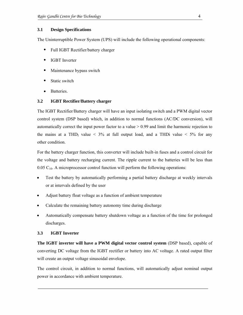
3.1 Design Specifications
The Uninterruptible Power System (UPS) will include the following operational components:
Full IGBT Rectifier/battery charger
IGBT Inverter
Maintenance bypass switch
Static switch
Batteries.
3.2 IGBT Rectifier/Battery charger
The IGBT Rectifier/Battery charger will have an input isolating switch and a PWM digital vector
control system (DSP based) which, in addition to normal functions (AC/DC conversion), will
automatically correct the input power factor to a value > 0.99 and limit the harmonic rejection to
the mains at a THDI value < 3% at full output load, and a THDi value < 5% for any
other condition.
For the battery charger function, this converter will include built-in fuses and a control circuit for
the voltage and battery recharging current. The ripple current to the batteries will be less than
0.05 C10. A microprocessor control function will perform the following operations:
Test the battery by automatically performing a partial battery discharge at weekly intervals
or at intervals defined by the user
Adjust battery float voltage as a function of ambient temperature
Calculate the remaining battery autonomy time during discharge
Automatically compensate battery shutdown voltage as a function of the time for prolonged
discharges.
3.3 IGBT Inverter
The IGBT inverter will have a PWM digital vector control system (DSP based), capable of
converting DC voltage from the IGBT rectifier or battery into AC voltage. A rated output filter
will create an output voltage sinusoidal envelope.
The control circuit, in addition to normal functions, will automatically adjust nominal output
power in accordance with ambient temperature.

Rajiv Gandhi Centre for Bio Technology 5
Inverter should be able to deliver full active power at Unity power factor( KVA=KW)
3.3.1 UPS compatibility to Load Power factor
UPS should support the full Power factor range (Lagging & leading) of load without any
deration in power rating
3.4 Static bypass switch
The static bypass switch will feature a separate power input and will consist of the following:
Static switches (SCR type), which can support overloads and short circuits downstream
of the UPS
A back-feed detection circuit as specified by IEC/EN 62040-1-1, clause 5.1.4
A bypass and maintenance bypass input isolating switch with auxiliary indicator contact
An output load switch.
The control logic will be handled by digital algorithms (using vector control techniques), similar
to those used for the rectifier and the inverter. The static bypass shall be equipped with a
back-feed protection device compliant with clause 5.1.4 of IEC/EN 62040-1-1; and a
relay signal contact for the control of the external back-feed isolator to be installed on
the bypass line upstream from the UPS.
3.5 Batteries
The VRLA, WET or NiCd batteries will feature an enclosure made of self-extinguishing
material.
The batteries will be housed in one or more racks/ cubicles and will be protected by fuses
located on each pole and via a dedicated switch.
Rajiv Gandhi Centre for Bio Technology 6
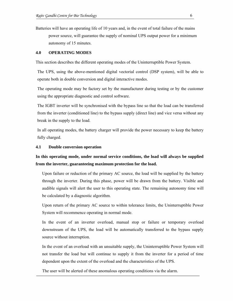
Batteries will have an operating life of 10 years and, in the event of total failure of the mains
power source, will guarantee the supply of nominal UPS output power for a minimum
autonomy of 15 minutes.
4.0 OPERATING MODES
This section describes the different operating modes of the Uninterruptible Power System.
The UPS, using the above-mentioned digital vectorial control (DSP system), will be able to
operate both in double conversion and digital interactive modes.
The operating mode may be factory set by the manufacturer during testing or by the customer
using the appropriate diagnostic and control software.
The IGBT inverter will be synchronised with the bypass line so that the load can be transferred
from the inverter (conditioned line) to the bypass supply (direct line) and vice versa without any
break in the supply to the load.
In all operating modes, the battery charger will provide the power necessary to keep the battery
fully charged.
4.1 Double conversion operation
In this operating mode, under normal service conditions, the load will always be supplied
from the inverter, guaranteeing maximum protection for the load.
Upon failure or reduction of the primary AC source, the load will be supplied by the battery
through the inverter. During this phase, power will be drawn from the battery. Visible and
audible signals will alert the user to this operating state. The remaining autonomy time will
be calculated by a diagnostic algorithm.
Upon return of the primary AC source to within tolerance limits, the Uninterruptible Power
System will recommence operating in normal mode.
In the event of an inverter overload, manual stop or failure or temporary overload
downstream of the UPS, the load will be automatically transferred to the bypass supply
source without interruption.
In the event of an overload with an unsuitable supply, the Uninterruptible Power System will
not transfer the load but will continue to supply it from the inverter for a period of time
dependent upon the extent of the overload and the characteristics of the UPS.
The user will be alerted of these anomalous operating conditions via the alarm.
Rajiv Gandhi Centre for Bio Technology 7
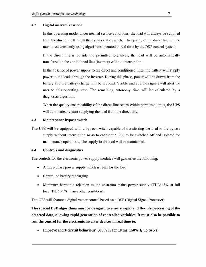
4.2 Digital interactive mode
In this operating mode, under normal service conditions, the load will always be supplied
from the direct line through the bypass static switch. The quality of the direct line will be
monitored constantly using algorithms operated in real time by the DSP control system.
If the direct line is outside the permitted tolerances, the load will be automatically
transferred to the conditioned line (inverter) without interruption.
In the absence of power supply to the direct and conditioned lines, the battery will supply
power to the loads through the inverter. During this phase, power will be drawn from the
battery and the battery charge will be reduced. Visible and audible signals will alert the
user to this operating state. The remaining autonomy time will be calculated by a
diagnostic algorithm.
When the quality and reliability of the direct line return within permitted limits, the UPS
will automatically start supplying the load from the direct line.
4.3 Maintenance bypass switch
The UPS will be equipped with a bypass switch capable of transferring the load to the bypass
supply without interruption so as to enable the UPS to be switched off and isolated for
maintenance operations. The supply to the load will be maintained.
4.4 Controls and diagnostics
The controls for the electronic power supply modules will guarantee the following:
A three-phase power supply which is ideal for the load
Controlled battery recharging
Minimum harmonic rejection to the upstream mains power supply (THDi<3% at full
load, THDi<5% in any other condition).
The UPS will feature a digital vector control based on a DSP (Digital Signal Processor).
The special DSP algorithms must be designed to ensure rapid and flexible processing of the
detected data, allowing rapid generation of controlled variables. It must also be possible to
run the control for the electronic inverter devices in real time to:
Improve short-circuit behaviour (300% In for 10 ms, 150% In up to 5 s)

Rajiv Gandhi Centre for Bio Technology 8
Have a synchronised (precise phase) angle between UPS output and bypass network, in
the event of mains voltage distortion
Highly flexible parallel operation.
5.0 Microprocessor control and diagnostics
Operation and control of the UPS should be provided through the use of microprocessor-
controlled logic. Indications, measurements and alarms, together with battery autonomy,
will be shown on a graphic liquid crystal display (LCD). The procedures for start up,
shutdown and manual transfer of the load to and from bypass will be explained in clear
step-by-step sequences on the LCD display.
Warning/fault: this page contains information regarding various anomalies concerning power
converters such as the bypass, rectifier, inverter and booster/charger. In addition to this
there is also warning and fault information relating to the battery and the load.
Events log: displays the date and time of important UPS events, alarms and other warnings.
Measurements: this page holds the full set of measurements for each functional block (rectifier,
bypass, booster/charger, batteries, inverter and load).
Battery: displays the battery status/values including temperature, cell voltage, capacity and run
time as well as commands for allowing the user to configure battery testing.
Tools: this page allows users to customize the settings of the LCD display and to select the
desired language, choosing between 15 languages.
5.1 Controls
The UPS will be provided with the following controls:
Inverter start
Inverter stop
Reset faults
Buzzer/mute alarm
5.2 Measurements
The UPS will provide the measurements (voltage, current and frequency) for every single
internal functional block and this information will be directly accessible on the display,
via the measurements button.

Rajiv Gandhi Centre for Bio Technology 9
5.3 Signals and alarms
The UPS must provide signals and alarms for every single functional block. These signals
must be directly accessible via the display, by clicking the warning and fault button.
The UPS will also:
Clearly display, upon mains failure, the remaining battery autonomy which will be a
function of battery status and charge (discharge curve, degradation, operating
temperature, etc)
Have three serial RS232 ports for compatibility and communications with special
peripheral units and for remote connections
Be able to support remote graphic measurement and signalling software
Be able to interface with a network monitoring system using SNMP slot-in cards
Provide a telemonitoring function (see description under section 6.0 "Telemonitoring")
A voltage-free input will also be provided to disable the static switches and all power converters
(EPO) in case of emergency.
Programmable I/O contacts (at least 4 voltage-free outputs and 2 inputs).
6.0 TELEMONITORING
This section defines the requirements of the system for remote monitoring and control from the
Service Centre.
6.1 Monitoring and control from service centre
The system will be capable of analysing UPS operation and electrical supply in order to identify
faults and thus prevent the occurrence of conditions likely to damage the equipment
protected by the UPS.
The system will guarantee single or parallel UPS surveillance, 24 hours a day for 365 days a year
by authorised technical personnel operating remotely. The system will provide a detailed,
preventive analysis of connected UPS, without any of the disruption associated with an
on-site visit.
The telemonitoring system will offer the following main features:
Continuous monitoring and control of the performance of end-user UPS
Rajiv Gandhi Centre for Bio Technology 10
Bi-directional communications between end-user UPS, Authorised Service Centre and its
authorised field service engineers
Automatic location of Service Engineers in the event of anomalous UPS functioning
(even at night and during public holidays)
Possibility of using graphic software for remote in-depth analysis and control
Periodic reports on UPS performance with advice from Service Centre engineers.
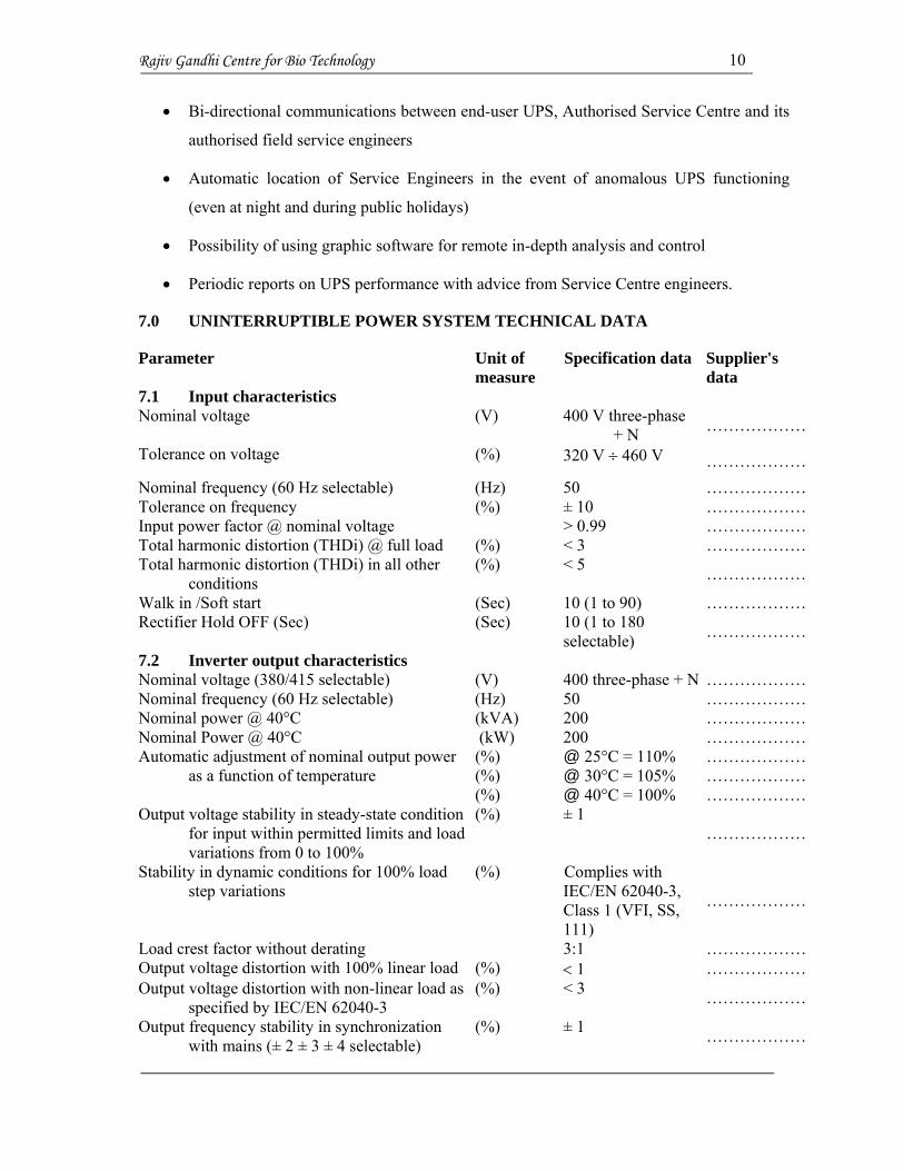
7.0 UNINTERRUPTIBLE POWER SYSTEM TECHNICAL DATA
Parameter Unit of measure
Specification data Supplier's data
7.1 Input characteristics Nominal voltage (V) 400 V three-phase
+ N ………………
Tolerance on voltage (%) 320 V 460 V ……………… Nominal frequency (60 Hz selectable) (Hz) 50 ……………… Tolerance on frequency (%) ± 10 ……………… Input power factor @ nominal voltage > 0.99 ……………… Total harmonic distortion (THDi) @ full load (%) < 3 ……………… Total harmonic distortion (THDi) in all other
conditions (%) < 5 ………………
Walk in /Soft start (Sec) 10 (1 to 90) ……………… Rectifier Hold OFF (Sec) (Sec) 10 (1 to 180
selectable) ………………
7.2 Inverter output characteristics Nominal voltage (380/415 selectable) (V) 400 three-phase + N ……………… Nominal frequency (60 Hz selectable) (Hz) 50 ……………… Nominal power @ 40°C (kVA) 200 ……………… Nominal Power @ 40°C Automatic adjustment of nominal output power
as a function of temperature
(kW) (%) (%) (%)
200 @ 25°C = 110% @ 30°C = 105% @ 40°C = 100%
……………… ……………… ……………… ………………
Output voltage stability in steady-state condition for input within permitted limits and load variations from 0 to 100%
(%) ± 1 ………………
Stability in dynamic conditions for 100% load step variations
(%) Complies with IEC/EN 62040-3, Class 1 (VFI, SS, 111)
………………
Load crest factor without derating 3:1 ……………… Output voltage distortion with 100% linear load (%) 1 ……………… Output voltage distortion with non-linear load as
specified by IEC/EN 62040-3 (%) < 3 ………………
Output frequency stability in synchronization with mains (± 2 ± 3 ± 4 selectable)
(%) ± 1 ………………
Rajiv Gandhi Centre for Bio Technology 11
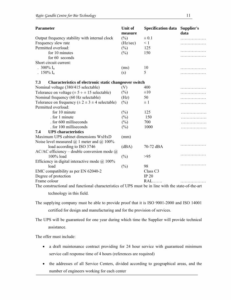
Parameter Unit of measure
Specification data Supplier's data
Output frequency stability with internal clock (%) ± 0.1 ……………… Frequency slew rate (Hz/sec) < 1 ……………… Permitted overload:
for 10 minutes for 60 seconds
(%) (%)
125 150 ………………
………………
Short circuit current: . 300% In . 150% In
(ms) (s)
10 5
……………… ………………
7.3 Characteristics of electronic static changeover switch Nominal voltage (380/415 selectable) (V) 400 ……………… Tolerance on voltage (± 5 ± 15 selectable) (%) ±10 ……………… Nominal frequency (60 Hz selectable) (Hz) 50 ……………… Tolerance on frequency (± 2 ± 3 ± 4 selectable) (%) ± 1 ……………… Permitted overload: for 10 minute
. for 1 minute . for 600 milliseconds . for 100 milliseconds
(%) (%) (%) (%)
125 150 700 1000
……………… ……………… ……………… ………………
7.4 UPS characteristics Maximum UPS cabinet dimensions WxHxD (mm) Noise level measured @ 1 meter and @ 100%
load according to ISO 3746 (dBA) 70-72 dBA ………………
AC/AC efficiency – double conversion mode @ 100% load (%) >95 ………………
Efficiency in digital interactive mode @ 100% load (%) 98 ………………
EMC compatibility as per EN 62040-2 Class C3 Degree of protection IP 20 Frame colour RAL……. ……………… The constructional and functional characteristics of UPS must be in line with the state-of-the-art
technology in this field.
The supplying company must be able to provide proof that it is ISO 9001-2000 and ISO 14001
certified for design and manufacturing and for the provision of services.
The UPS will be guaranteed for one year during which time the Supplier will provide technical
assistance.
The offer must include:
a draft maintenance contract providing for 24 hour service with guaranteed minimum
service call response time of 4 hours (references are required)
the addresses of all Service Centers, divided according to geographical areas, and the
number of engineers working for each center

Rajiv Gandhi Centre for Bio Technology 12
Indication of main telemonitoring installations in operation.
8.0 MISCELLANEOUS PROVISIONS
This section defines details of services, activities and means necessary to complete the
supply of the Uninterruptible Power System.
8.1 Documentation
All technical documents issued by the Supplier, in particular the user handbook and the
installation, maintenance and troubleshooting guides must be in English.
8.2 Spare parts
The Supplier may include a list of recommended spare parts in the offer for at least two and/or
five years.
8.3 Packaging
The Supplier will ensure that all equipment is suitably packaged.
8.4 Shipment
The Supplier will ensure that the equipment is shipped to the specified address on the agreed
date.
8.5 Commissioning
Commissioning costs will be payable by the Supplier who will be responsible for the work done
and the personnel involved.
Technical personnel will be trained to meet the requirements of current work safety standards.
8.6 Service hot line
The Supplier will indicate the service centre nearest to the place of installation of the
equipment supplied under the contract.
The service centre indicated must be able to provide routine maintenance services and must be
able to respond to urgent calls at the terms and conditions specified by the Buyer.
II. SPECIFICATION AND TECHNICAL PARTICULARS FOR PLC BASED
SYNCHRONIZATION SYSTEM
The system is for the synchronization of 2 Diesel Generators. A single and sophisticated system
for generator Synchronization and AMF functionality of the transformer is considered.

Rajiv Gandhi Centre for Bio Technology 13
The load dependent switching of the breakers is done by the PLC. The necessary
electrical interlocks of the DG switchgear with the mains power and for the various
feeders is done using the PLC. DG synchronization system to ensure more efficient
running of DG’s as well as less fuel consumption per unit of running DG’s is considered.
Generator Synchronising and protection module of approved make is to be used for the
application. 2 nos. of synchronization modules are considered for the operation. One
synchronization module per Generator is required. An Operator Display module for the
visualization of the Process parameters on the PLC Panel itself is required. PC is to be
connected to PLC over bus network. Bus is the Industrial network, which offers a high-
speed data communication at a speed of 12 MBPS which ensures very smooth and
trouble free data communication between different process elements. The system starts
the DG’s automatically on the event of power failure or any unhealthy power condition
on the mains power supply persists more than 5 seconds, such as: A. Failure of any of the
phases B. Under voltage conditions (10% below normal voltage of 415V AC) C. Failure
of any of the transformers or tripping of transformer protective relay. On failure of Grid
supply, the mains ACB will be switched off and first DG, selected either depending on
the average load for the last 15 minutes before the power failure or as per the pre-
programmed sequence the Master DG will come immediately in line. The sequence and
master DG’s can be altered any time later through the SCADA or Display. The transfer of
the loads takes place only when the generator output reaches 90% of its rated voltage and
frequency.
III. SPECIFICATION AND TECHNICAL PARTICULARS FOR CABLE
MANAGEMENT SYSTEM
Wall trunking with cover shall be made up of Lead free Polyvinylchloride material as per EN
50085-2-1 and shall be ROHS complied. The trunking shall have smooth surface finish
without sharp edges and Burrs. The trunking shall have IP 30 Protection against access to
hazardous parts and shall be non-flame propagating. Wall trunking channels shall be
made of lead free polyvinyl chloride with ROHS compliance. With a standard length of
2 meter, size 108.50mm height x 60 mm depth (or higher) suitable for fix any make
switches and sockets. The system must have a base perforation so as to allow installation
in the wall. The WDK 60110 cover must have slide external locking; and with 4 cover
clips each in every 2 meter length for a better locking with base trunk. The trunking shall
have all accessories like internal corner cover, external corner cover, T intersection cover,

Rajiv Gandhi Centre for Bio Technology 14
flat angle cover etc for complete cable management. The wall trunking shall be of Cream
in colour and the standard size of the wall trunking shall be of dimensions mentioned
below.
IV. SPECIFICATIONS FOR 415V AUTOMATIC POWER FACTOR CORRECTION
CAPACITOR BANKS AND CAPACITORS WITH HARMONIC SUPPRESSION
FILTER
4.1 POWER FACTOR CAPACITORS – 270 kVAR & 190 kVAR
Following shall be the specifications of capacitors used in the banks:
1 Rated Voltage (V) : 415 2 Rated frequency (Hz) : 50 3 Construction : 2 layer film + foil 4 Guaranteed maximum reduction
in kVAR rating after the following periods from the date of commissioning
:
a. One Year : � 2% b. Two Years : � 5% 5 Guaranteed maximum loss in
watts per kVAR : 0.8 to 1W per kVAR
6 Container material for capacitor in bank
: Fully metal treated, powder coated hermetically sealed sheet steel housing
7 Impregnate : Non-PCB non-hazardous 8 Earthing terminals : 2 No, to be provided 9 Permissible over-voltage : 10% 10 Permissible over-current
: 30%
11 Reference Standard : IS: 2834 12 Reactor : 7% harmonic block reactor needs to be
provided in series with each Individual capacitor bank. It shall be designed for low temperature rise and low flux density. It shall be of high linearity.
Rajiv Gandhi Centre for Bio Technology 15
4.2 APPROVAL AND CERTIFICATION
The banks and capacitors shall have CPRI test certificates.
4.2.1 APPROVAL BY ELECTRICAL INSPECTORATE
The bank shall be manufactured to comply with the requirements of the Electrical Inspectorate
of the State. The Contractor shall be responsible to get the approval of the Electrical
Inspectorate for the equipment and components supplied.
Following drawings and details shall be furnished:
a. Front view of the bank with arrangement of all compartments, compartment doors, handles,
knobs, push buttons, indicating lamps and other components.
b. Typical cross sections of the bank to show the arrangement of bus bars, capacitors, fuses,
contractors, interconnections and cable terminating facility with sizes of bus bars.
Interconnections and clearances.
c. Drawings of bus bars with clearances and support details.
d. Ventilation arrangement inclusive of fan, if provided, with control arrangement.
e. Schematic wiring drawings of power, control, metering and protection circuits.
4.2.2 DRAWINGS
The Contractor shall prepare and furnish to the Employer detailed drawings of the bank and its
parts with all the required information within fifteen days of the letter of intent. The
manufacture shall be taken up only after receipt of the approved drawings from the Employer.
The Contractor shall take action in this matter in such a manner that the process of submission
of drawings and details and their approval by Employer are completed in time to adhere to the
stipulated delivery period.
The drawings and details to be furnished for Employer’s approval shall include the following;
a. Front view, plan, end views and sectional views of the bank to clearly show all details r
relating to arrangement of various components, interconnections, clearances, etc.
b. Schematic wiring diagrams of the main and auxiliary circuits.
c. Bill of materials giving details of designation, make, type, ratings, etc of the various
pieces of equipment mounted on the bank.

Rajiv Gandhi Centre for Bio Technology 16
4.2.3 TESTS
All standard tests as specified in relevant Indian Standards shall be carried out by the
manufacture on the bank and its parts. These tests are to be carried out in the presence of the
representative of the Employer and detailed test reports are to be furnished to the Employer.
Following tests shall be carried out:
a. Verification of the bank as per the approved drawings.
b. Visual inspection of bank for compliance with specifications, workmanship, etc.
c. Operational tests on all the Switchgear.
d. Operational and accuracy tests on the protective gear such as relays, annunciation system,
indicating lamps, etc. by injecting the required voltage/current into the circuits.
e. Insulation resistance measurements of power circuits.
f. Insulation resistance measurements of control circuits.
g. High voltage test using 2.5 kV for one minute between each pole and earth.
h. Insulation resistance measurements under items (c) and (d) are to be carried out after high
voltage test also.
Test results shall be recorded and furnished to Client/Consultant.
4.2.4 INSPECTION
The Contractor shall intimate the Employer sufficiently in advance of the readiness of the bank
for inspection and testing. The Contractor shall provide all required facilities to the Employer to
carry out the inspection and witnessing of tests to the satisfaction of the latter.
4.2.5 SERVICE CONDITIONS
Equipment supplied shall be suitable for continuous operation under the conditions specified. If
any further detail relating to service conditions is required the Contractor shall specifically
request for such detail to the Employer.
4.2.6 APFC RELAY
APFC Relay shall be microprocessor controlled type and shall have automatic C/k ratio
selection with step status indications and digital display of power factor. The controller shall
provide protection by switching off the system when the harmonic distortion level increases
Rajiv Gandhi Centre for Bio Technology 17
specific levels. APFC relay shall be capable of being programmed to disconnect capacitor steps
in the event of harmonic overload exceeding pre-set limits
4.2.7 GENERAL CONSTRUCTION
The bank consists of power factor capacitors connected to a common bus through individual
sets of fuses and contactors. Each capacitor is to be switched in and out by means of its
contactor. Only air-break contactors of double-break construction rated for uninterrupted duty
as defined in IS: 2959 shall be used. The contractor shall have adequate number of auxiliary
contacts. The operating coil voltage shall be 415V, 50Hz, AC unless otherwise specified. The
contactor shall be of adequate duty classification. Every contactor shall have a minimum of 2
Nos. “NO” and 2 Nos. “NC” auxiliary contacts available for wiring control circuits. Each
contactor shall be provided with ON and OFF indicating lamps.
The bank shall be of sheet-steel, totally enclosed, dust tight, vermin-proof, flush dead front,
modular and fully compartmentalized construction. There shall be an independent compartment
for each capacitor with its set of fuses and contactor. The indicating lamps and push buttons
shall be provided by the side of the compartment door. Adequate shrouding shall be provided to
prevent accidental contracts with parts which may remain live when the door is in open
position. Each compartment has an independently interlocked door with padlocking facility.
The bank shall be easily extensible at both ends.
The bank shall be complete with an integral base framework of adequate design and
construction so that the board can be directly mounted using suitable foundation/anchoring
bolts. Bolt holes shall be provided in the bottom framework for the foundation bolts.
It shall be suitable for functioning efficiently and continuously under the service conditions
specified.
4.2.8 ENCLOSURE
The enclosures of the bank shall be made of cold rolled sheet steel up to 2.5mm thickness above
which thickness hot-rolled steel may be used. The enclosure shall be of floor-mounting, free-
standing and self-supporting type construction.
The enclosure shall be so designed and constructed as to prevent the entry of dust, water, insects
and vermin. All doors, detachable cover, plates etc shall be provided with effective gaskets. The
covers shall be provided with fasteners which would ensure tight closing of the covers by

Rajiv Gandhi Centre for Bio Technology 18
properly compressing the gaskets. Ventilating louvers, if provided shall be provided with fine
brass wire mesh screens.
The enclosures may be of double-front construction where access will be available into the bank
both from front and rear. All handles, knobs, pushbuttons, indicating lamps, annunciations,
meters and relays of switchgear shall be mounted in the front of the bank.
Every compartment in the bank shall be totally segregated from other compartments by sheet
enclosure on all sides with insulating bushes for entry and exit of power and control wiring and
interconnections.
Suitably inscribed plastic /bakelite designation labels shall be fixed on the compartment doors.
Bus bar chambers shall be provided with screwed covers. Cables alleys meters and relay
compartments and switchgear compartments shall be provided with hinged doors which shall be
closed tight by means of captive screws with moulded plastic knobs. All the hinges shall be
concealed type.
The covers and doors shall be properly stiffened by means of ribs or other stiffeners against
wobbling.
The minimum thickness of cold-rolled sheet steel used for the fabrication of the bank shall be
2mm. The folded sections forming the base and vertical framework shall be fabricated out of
steel having a minimum thickness of 3mm. Comparatively large covers and doors shall be
fabricated using 3mm thick sheet steel.
The structure of the enclosure shall be strong and rigid and shall not suffer any distortion during
transport, handling or erection. The different parts of the enclosure shall be able to withstand
without any shake or vibration, the static and dynamic loading of various equipment installed in
the enclosure. The bank shall be stable under all the required conditions of loading and
operation. Adequate lifting hooks shall be provided.
The height of enclosure shall be the same throughout the bank.
The metalwork of the enclosure shall be fabricated to good quality finish with the surface level
and smooth without any flaw. The corners shall be rounded.
The metalwork of the enclosure shall be fabricated in a shop with adequate facilities such as
power-operated guillotine shears, press brakes, presses, powder-coating plant, etc. The metal
work shall be powder coated after treatment.

Rajiv Gandhi Centre for Bio Technology 19
All fabricated steel parts of the enclosure and framework shall be subjected to the following
treatment before powder coating:
a. Degreasing using hot alkaline solution
b. Rinsing with cold water to remove all traces of alkaline solution.
c. Pickling using dilute sulphuric acid and pickling inhibitors to remove oxide, scale and rust
formation
d. Rinsing with cold water to remove all traces of acidic solution.
e. Phosphate using zinc phosphate solution.
f. Rinsing with cold water to remove all traces of phosphate solution.
g. Passivating by rinsing in de-oxalate solution to neutralite traces of salts.
h. Drying with compressed air
V. TECHNICAL SPECIFICATIONS OF EXTERNAL LPS ,STRUCTURAL
EARTHING AND EQUIPOTENTIAL BONDING FOR BUILDINGS
APPLICABLE STANDARDS
IEC 62305: Protection against lightning
IEC 62305 -1 ; Protection against lightning: General principles
IEC 62305 -2 ; Protection against lightning: Risk management
IEC 62305 -3 ; Protection against lightning: Physical damage to structures and life hazard
IEC 62305 -4;Protection against lightning: Electrical and electronic systems within
structures
IEC 61643-1: - Surge Protective Devices Connected to Low-Voltage Power Systems:
Performance requirements and testing methods. IEC 61643-12: - Surge Protective
Devices Connected to Low-Voltage Power Systems: Selection and application principles
5.1 FOUNDATION EARTHING:
Foundation earthing comprises conductors which are installed in the foundation below ground.
The mesh size of the foundation earthing shall be 10m x 10m installed in the clean
concrete layer at the bottom of the foundation. The mesh shall be firmly connected to the
steel of the concrete with clamp ( Type :250/A-FT , Art no :5313015 ) in each 1 meter.

Rajiv Gandhi Centre for Bio Technology 20
The conductor of foundation earthing shall be galvanised solid tape with area cross section of 90
sq mmwith 3mm min thickness (30x3 mm). The conductor shall be continuous at least 60
meter.
A separate dedicated GI strip shall be run on the columns and must be connected to the steel
reinforced steel available in the columns. The conductor shall be ultimately connected to
the mesh of the foundation earthing. The upper end of the dedicated conductor in the
column must be connected to the roof air termination system.
Using the dedicated conductor in the beams and columns will ensure the electrical continuity
between all steel conductors, thus reducing the effects of the lightning current.
The reinforced steel available inside the concrete shall be used for earth termination system and
equipotential bonding for electrical system. All the rooms must have an extended local
equipotential bonding point extended from the structural earthing.The component must
be stainless steel (205/BM10-VA , Art No: 5420016)
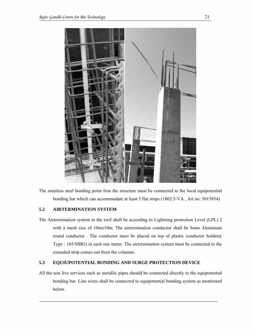
Rajiv Gandhi Centre for Bio Technology 21
The stainless steel bonding point fron the structure must be connected to the local equipotential
bonding bar which can accommodate at least 5 flat strips (1802/5-VA , Art no: 5015854)
5.2 AIRTERMINATION SYSTEM
The Airtermination system in the roof shall be according to Lightning protection Level (LPL) 2
with a mesh size of 10mx10m. The airtermination conductor shall be 8mm Aluminum
round conductor . The conductor must be placed on top of plastic conductor holders(
Type : 165/MBG) in each one meter. The airtermination system must be connected to the
extended strip comes out from the columns.
5.3 EQUIUPOTENTIAL BONDING AND SURGE PROTECTION DEVICE
All the non live services such as metallic pipes should be connected directly to the equipotential
bonding bar. Line wires shall be connected to equipotential bonding system as mentioned
below.
Rajiv Gandhi Centre for Bio Technology 22
Type of Network – 3 phase, 4 wire.
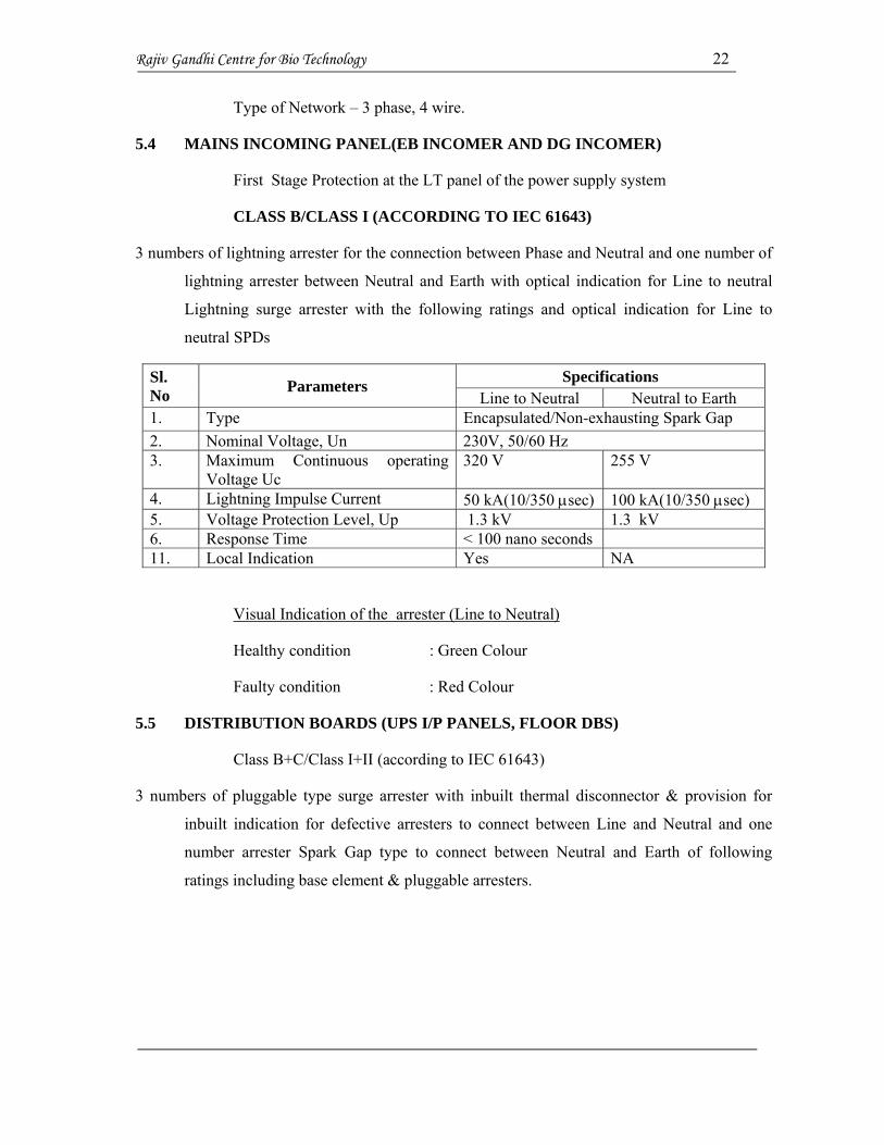
5.4 MAINS INCOMING PANEL(EB INCOMER AND DG INCOMER)
First Stage Protection at the LT panel of the power supply system
CLASS B/CLASS I (ACCORDING TO IEC 61643)
3 numbers of lightning arrester for the connection between Phase and Neutral and one number of
lightning arrester between Neutral and Earth with optical indication for Line to neutral
Lightning surge arrester with the following ratings and optical indication for Line to
neutral SPDs
Sl. No Parameters Specifications
Line to Neutral Neutral to Earth 1. Type Encapsulated/Non-exhausting Spark Gap 2. Nominal Voltage, Un 230V, 50/60 Hz 3. Maximum Continuous operating
Voltage Uc 320 V 255 V
4. Lightning Impulse Current 50 kA(10/350 sec) 100 kA(10/350 sec) 5. Voltage Protection Level, Up 1.3 kV 1.3 kV 6. Response Time < 100 nano seconds 11. Local Indication Yes NA
Visual Indication of the arrester (Line to Neutral)
Healthy condition : Green Colour
Faulty condition : Red Colour
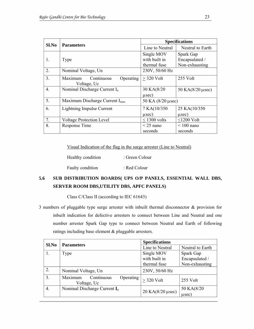
5.5 DISTRIBUTION BOARDS (UPS I/P PANELS, FLOOR DBS)
Class B+C/Class I+II (according to IEC 61643)
3 numbers of pluggable type surge arrester with inbuilt thermal disconnector & provision for
inbuilt indication for defective arresters to connect between Line and Neutral and one
number arrester Spark Gap type to connect between Neutral and Earth of following
ratings including base element & pluggable arresters.
Rajiv Gandhi Centre for Bio Technology 23
Sl.No Parameters Specifications
Line to Neutral Neutral to Earth
1. Type Single MOV with built in thermal fuse
Spark Gap Encapsulated / Non-exhausting
2. Nominal Voltage, Un 230V, 50/60 Hz
3. Maximum Continuous Operating Voltage, Uc
> 320 Volt 255 Volt
4. Nominal Discharge Current In 30 KA(8/20 sec)
50 KA(8/20 sec)
5. Maximum Discharge Current Imax 50 KA (8/20 sec) 6. Lightning Impulse Current 7 KA(10/350
sec) 25 KA(10/350
sec) 7. Voltage Protection Level < 1300 volts <1200 Volt 8. Response Time < 25 nano
seconds < 100 nano seconds
Visual Indication of the flag in the surge arrester (Line to Neutral)
Healthy condition : Green Colour
Faulty condition : Red Colour
5.6 SUB DISTRIBUTION BOARDS( UPS O/P PANELS, ESSENTIAL WALL DBS,
SERVER ROOM DBS,UTILITY DBS, APFC PANELS)
Class C/Class II (according to IEC 61643)
3 numbers of pluggable type surge arrester with inbuilt thermal disconnector & provision for
inbuilt indication for defective arresters to connect between Line and Neutral and one
number arrester Spark Gap type to connect between Neutral and Earth of following
ratings including base element & pluggable arresters.
Sl.No Parameters Specifications Line to Neutral Neutral to Earth
1. Type Single MOV with built in thermal fuse
Spark Gap Encapsulated / Non-exhausting
2. Nominal Voltage, Un 230V, 50/60 Hz 3. Maximum Continuous Operating
Voltage, Uc > 320 Volt 255 Volt
4. Nominal Discharge Current In 20 KA(8/20 sec) 50 KA(8/20 sec)

Rajiv Gandhi Centre for Bio Technology 24
5. Maximum Discharge Current I max 40 KA 50 KA (8/20 sec)
6. Voltage Protection Level < 1400 Volts < 1200 Volts 7. Response Time < 25 nano
seconds < 100 nano seconds
Visual Indication of the flag in the surge arrester (Line to Neutral)
Healthy condition : Green Colour
Faulty condition : Red Colour
Note: In US, SPD is called as TVSS- Transient Voltage Surge Suppressor. BUT, IEEE also
changed the name to SPD in 2009 April. Now, throughout the world, the common name
is SPD.
F1, F
2, F
3 - :
Inco
min
g AC
B/M
CC
B/SF
U
F4, F
5, F
6 -:
Bac
k up
fuse
for S
urge
Arr
este
r
R,Y
,B a
nd N
-:
RY
B an
d N
Bus
bar
or l
oopi
ng a
fter t
he in
com
er
SPD
1
SPD
4
R
Y
B
N
PE
F4 F5 F6
F1
F2
F3
SPD
2
SPD
3
Connection diagram for SPD for 3 phase 4 wire

Rajiv Gandhi Centre for Bio Technology 25
List of Approved Makes/Brands
The contractor shall quote his rates on the basis of the price of best quality product of the
brand/make. In case any particular brand of item is not acceptable to the client, the
contractor shall supply items of other approved brands without extra cost.
C ELECTRICAL WORKS
MATERIALS MAKES/BRANDS NAME
Alternator
Stamford / Leroy Somer / KEC / BHEL /
Crompton Greaves
APFC Panels L&T / Sprague / EPCOS / INEL
Battery Charger
Keltron / Automatic Electric / Sabnife / Waves
Electronics
Bus Riser / Bus duct Schneider / L&T / Legrand / GE
Cable Gland Dowells / Polycab / Jaison / Comet
Capacitors
Crompton Greaves / Schneider / Mehar / Shreem
/ Sprage / Epcos
Cable Management OBO Betterman / Legrand / MK
Ceiling Roses/Batton Holder/Angle
Batton Precision / Anchor / legrand / MK / Schneider
Contactors L&T / ABB / GE / BCH / Schneider
Crimping Sockets Dowells/ Polycab / Jaison / Comet
Current transformer / PT PGR Power / Intrans / Indus / Kappa / Kapco
Diesel Generator Engine
Caterpillar / Mitsubishi / Cummins / Volvo /
Perkins / Ashok Lyland / Kirloskar
Distribution Boards GE / Legrand / Siemens / Schneider / L&T
Dry Type Transformers ABB / Intrans/ Schneider / BHEL
LT Panel Enclosure Rittal / Hensel / Mehar / Megavin
Ceiling / Exhaust fan
Bajaj / Crompton Greaves / Havells / Khaitan /
Usha / Almonard
HT / VCB Panel Siemens / ABB / Schneider
HT & LT Cables Polycab / Gloster / Havells / Finolex / V-Guard

Rajiv Gandhi Centre for Bio Technology 26
HT Cable Termination Kit Raychem/ M-Seal [Heat shrinkable type]
HT Panels ABB / Siemens / Schneider
Indicating Meters Socomec / L&T / Elmeasure / Conzerv
Industrial Sockets & Tops Clipsal / Hensel / Legrand / Schneider / Anchor
Isolator / SFU L&T / ABB / Siemens / Schneider
KWHR, KW Meters / TOD Socomec / L&T / Enercon
Light Fixtures Philips / Wipro / Havells / GE / Bajaj / Crompton
Lightning Arrestor OBO Bettermann / Eritech / Foudretech
LT ACBs L & T / ABB / Schneider / Siemens
MCB, RCBO & ELCB Legrand / ABB / Schneider / L&T / Siemens
MCCB's L&T / ABB / Siemens / Schneider
Metal Clad Sockets / Top
Crompton Greaves / Indo-Kopp / GE / Legrand /
Havells / Hensel-Walther/ Clipsal /
Schneider
Multifunction Meters L&T / Conserv / Enercon / El measure
PLC / Synchronization ABB / Siemens / BCH Electric Ltd / DEIF
PVC Conduit Balco / Finolex / Avon Plast / Supreme /
Precision
PVC wires Finolex / Polycab / Havells / RR Cable / V-Guard
Relay & Controls Areva / L&T / Siemens / GE / ABB / Schneider
RMU Siemens / ABB / Schneider / Crompton Greeves
Storage Battery Exide / STANDARD / Amaron
Switches/Sockets Anchor / Legrand / Schneider / L&T / MK
UPS APC / Legrand / Emerson / TATA Liberty
Load Banks Havells / GE / Legrand / ABB / Siemens /
Schneider
Cable Tray OBO Bettermann / Copper B Line / Panduit
Telephone/Network cable Havells / Finolex / RR cable / V-guard /Amber
MDF Krone
Other Items Approval from Client/ Consultant