tender document (volume i, ii & iii) january 2012 …€¦ · ... ii & iii) january 2012...
TRANSCRIPT
KONKAN RAILWAY CORPORATION LIMITED (A Government of India Undertaking)
TENDER DOCUMENT (Volume I, II & III)
JANUARY 2012
TENDER DRAWING/REPORTS ETC.
VOLUME II/III
TENDER FOR “BALANCE WORK OF DESIGN AND CONSTRUCTION OF
SPECIAL BRIDGE ACROSS THE RIVER ANJI KHAD BETWEEN
KM 38/430 TO 39/087” AND “CONSTRUCTION OF CUT PROF ILE AND
PROTECTION WORK ON KATRA END HILL” ON THE KATRA-DH ARAM
SECTION OF THE UDHAMPUR-SRINAGAR-BARAMULLA NEW B.G.
RAILWAY LINE PROJECT, J&K STATE, INDIA.
CORPORATE/REGISTERED OFFICE KONKAN RAILWAY CORPORATION LTD, 5th FLOOR, BELAPUR BHAVAN, CBD – BELAPUR, NAVI MUMBAI (MAHARASHTRA) 400 614
HEAD OFFICE KONKAN RAILWAY CORPORATION LTD, HEAD OFFICE USBRL PROJECT, SATYAM COMPLEX, MARBLE MARKET, TRIKUTA NAGAR EXTN. JAMMU – 180 010 (J&K).
PROJECT OFFICE
KONKAN RAILWAY CORPORATION LTD, PROJECT OFFICE USBRL PROJECT REASI JYOTIPURAM ROAD REASI – 182 311, (J&K).

Design & Construction of Special Bridge Anji Khad
Konkan Railway Corporation Ltd. Signature of Tenderer
INDEX
Konkan Railway Corporation Ltd. Signature of Tenderer
Design & Construction of Special Bridge Anji Khad
INDEX
Annexure Description
Page No
A Key Plan
1
B Photographs of site location
2 - 3
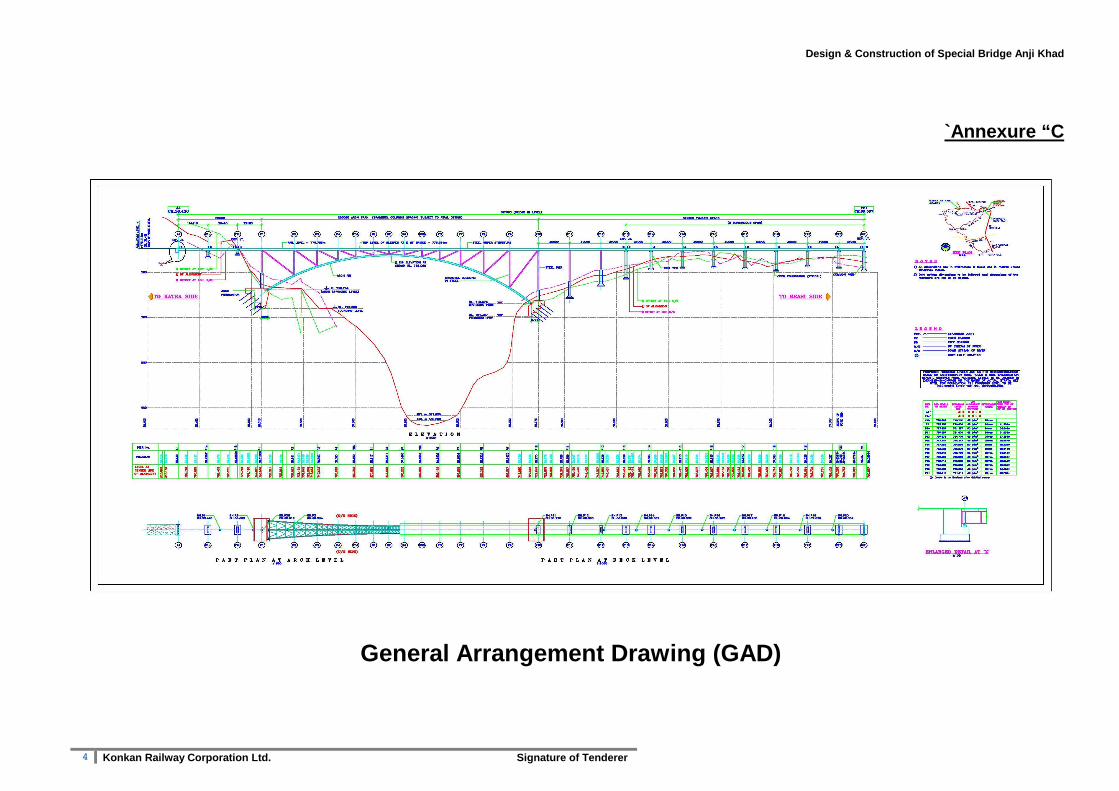
C General Arrangement Drawing (GAD)
4
D Design Basis Note (DBN)
5 - 66
E List of Reports, documents available in HQ office at Jammu
67
F Details of structural steel available at Reasi yard
68

Design & Construction of Special Bridge Anji Khad
1 Konkan Railway Corporation Ltd. Signature of Tenderer
Annexure “A”
Design & Construction of Special Bridge Anji Khad
2 Konkan Railway Corporation Ltd. Signature of Tenderer
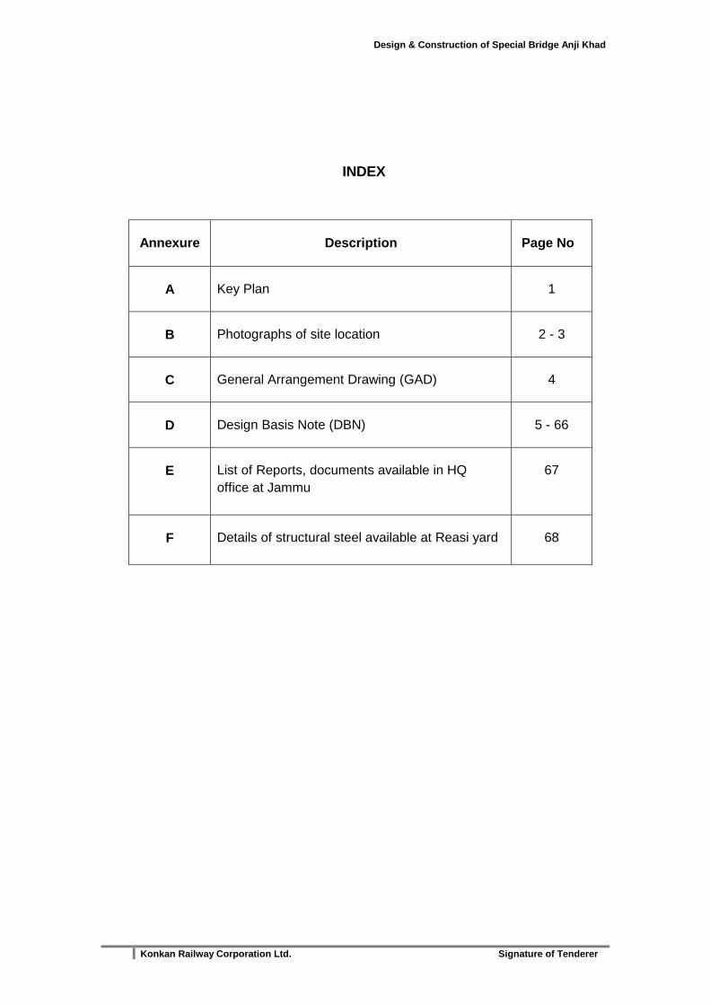
Annexure “B”
Photographs of site location
View of Anji Khad Bridge Site from Reasi End
Design & Construction of Special Bridge Anji Khad
3 Konkan Railway Corporation Ltd. Signature of Tenderer
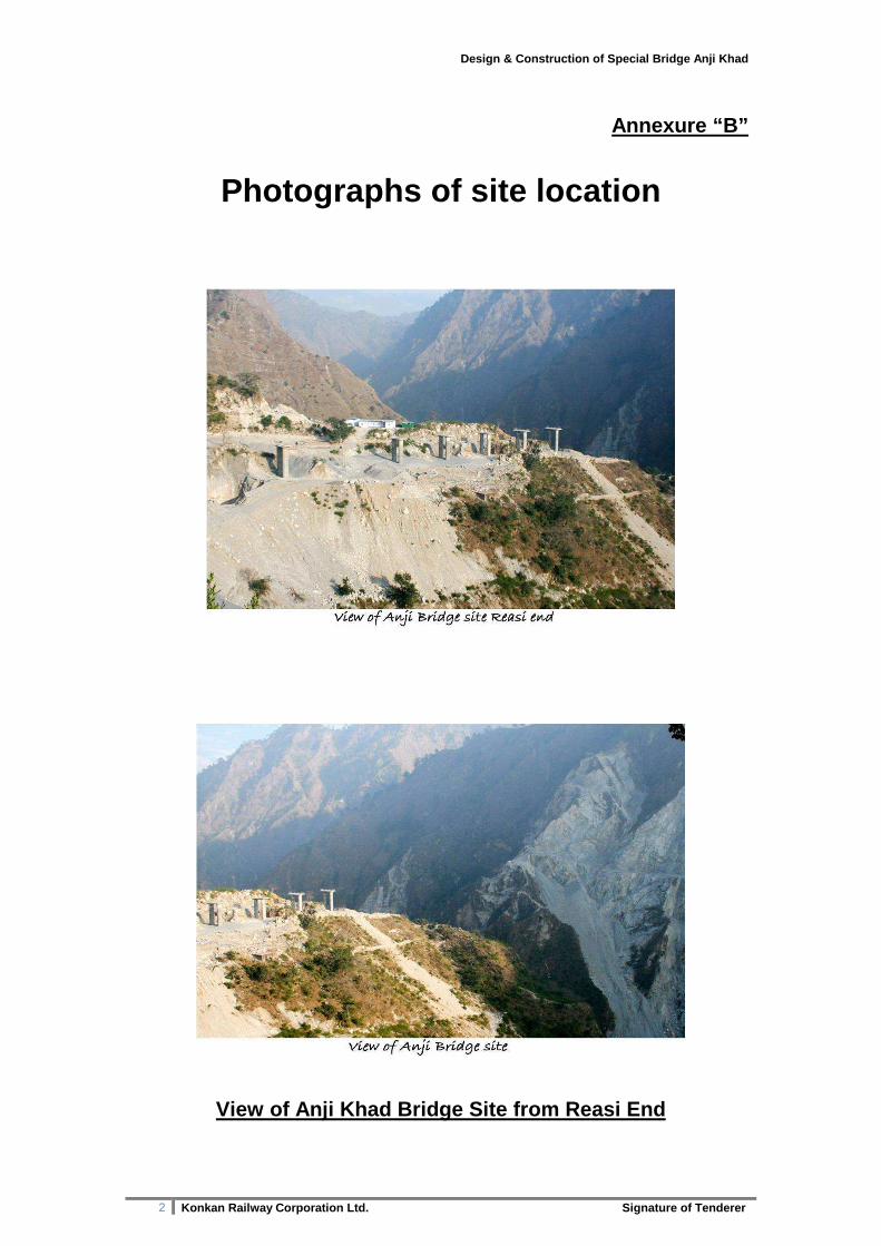
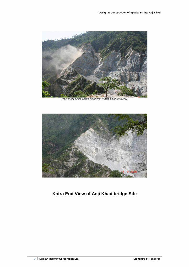
Katra End View of Anji Khad bridge Site
Design & Construction of Special Bridge Anji Khad
4 Konkan Railway Corporation Ltd. Signature of Tenderer
`Annexure “C
General Arrangement Drawing (GAD)

Design & Construction of Special Bridge Anji Khad
5 Konkan Railway Corporation Ltd. Signature of Tenderer
Annexure “D”
KONKAN RAILWAY CORPORATION LTD. (A GOVERNMENT OF INDIA UNDERTAKING)
USBRL PROJECT
DESIGN BASIS NOTE ANJI KHAD BRIDGE
11.04.2011

Design & Construction of Special Bridge Anji Khad
6 Konkan Railway Corporation Ltd. Signature of Tenderer
INDEX
Sl. No. Description
1 List of abbreviations used
2 Design basis note
3 Salient Features of Design Basis
4 Design Standards
Annexure A
1 Table 1 : List of clauses in IRS Steel Bridge Code that shall be given priority over BS 5400
2 Table 2 : List of design issues where no provisions are available in IRS for this type of structure and the codes to be adopted in such cases
3 Table 3: List of deviation from IS/IRS codes not applicable for Anjikhad bridge design
Annexure B
1 Table 1: General and material
2 Table 2: Loads
3 Table 3: Characteristic strength and partial safety factor for material
4 Table 4: Fatigue considerations
5 Table 5: Other design features of Design basis of Anjikhad Bridge
6 Table 6: Traffic details of Broad Gauge train (fatigue load model for MBG loading)
7 Table 7: Description of Broad Gauge trains
Annexure C - Load combination and partial load factors
1 Legend for characteristic loads
2 Steel structure
3 Table for partial safety factors for steel structures
4 Table for partial safety factors for Reinforced concrete structures
Annexure D
1 Extract of site specific design earthquake parameters for Anjikhad Railway bridge, J&K
Annexure E
1 Topographical Model Study Anjikhad Arch Bridge Jammu & Kashmir, India

Design & Construction of Special Bridge Anji Khad
7 Konkan Railway Corporation Ltd. Signature of Tenderer
LIST OF ABRIVATIONS USED
1. BG Broad Gauge
2. IRS Indian Railway Standards
3. BS British Standard Codes
4. UIC International Union of Railways
5. IS Indian Standards
6. AASHTO American Association of State Highway and
Transportation Officials
7. LWR Long Welded Rail
8. SEJ Switch Expansion Joint
9. ASTM American Society for Testing And Materials
10. MBG Modified Broad gauge
11. HSFG High Strength Friction Grip
12. OHE Overhead Equipments
Design & Construction of Special Bridge Anji Khad
8 Konkan Railway Corporation Ltd. Signature of Tenderer
DESIGN BASIS NOTE FOR ANJI KHAD BRIDGE
1. Salient Features of Design Basis
1.1 Introduction
This document highlights salient features of design basis of bridge over river Anji Khad. The bridge shall be designed with steel arch superstructure. There are important implications associated with the design decision and the conventional approach is not sufficient. A new concept in design with current international practices is therefore required to be applied for optimum and safe design. This design basis is prepared to achieve this objective.
1.2 Concept and Structural System
The structural concept of bridge over river Anji Khad is for a large arch span across the Khad with approach viaducts on either side. The bridge shall be designed for single line BG.
1.3 Codes and order of precedence
It is proposed to use Indian Railway Standards (IRS) wherever applicable and supplement them with BS, UIC and other international standards if required.
1.4 Design Loads
Design loads shall be taken from the IRS codes and applied as nominal loads for the limit state analysis. Wind loads shall be derived using physical topographic models of the site and tested in a wind tunnel laboratory. Wind tunnel test results shall be used to extract equivalent static wind loads, which shall be used in the final structural analysis. These equivalent static wind loads shall take into account wind-induced dynamic actions of the bridge, as well as size reduction effects related to patchy distribution of wind pressure peaks. The seismic load shall be taken from Annexure- D. Blast load shall be taken from Table-2 of Annexure ‘B’. Fatigue assessment shall be done as per BS: 5400 Part –10 for which necessary load spectra shall be as per Table No. 4 of Annexure B. The load trains to be considered for design shall be as per Table 6 & 7 of Annexure ‘B’.
1.5 Load Combinations and Partial Load factors
For concrete structures the combination of loads and partial safety factors shall be taken according to Table-12 given in para 4.0 of Annexure ‘C’. For steel structures the combination of loads and partial safety factors will be taken according to Table given in para 2.0 & 3.0 of Annexure ‘C’.

Design & Construction of Special Bridge Anji Khad
9 Konkan Railway Corporation Ltd. Signature of Tenderer
1.6 Wind Tunnel Test – (Included as Annexure E)
Following Wind tunnel tests have been carried out as per earlier approved GAD.
A. the topographic effects of the site on the reference wind speed;
B. The derivation of gust data for gust buffeting analysis.
The information given in aforesaid Wind Tunnel test should be used for the design of arch to the extent possible. If the configuration of arch is such that, the result of wind tunnel test already carried out cannot be applied, appropriate wind tunnel test shall be carried out.
1.7 Structural Deformation Limits
Structural Deformation Limits shall be as per Table 5 of Annexure ‘B’.
1.8 Partial Safety Factors and Specifications for M aterial
Partial safety factors for concrete shall be taken as per IRS Concrete Bridge Code, and for Steel as per BS: 5400. For other materials these shall be taken from
relevant codes. Materials shall confirm to specification given in Table 1 of Annexure
– B
1.9 Bearings and Expansion Joints
Spherical Knuckle Bearings shall be provided over piers/trestles and designed as per BS: 5400. Expansion joints shall be provided wherever required.
1.10 Deck Furniture
Walkway of 1.5 m width with 1.5m high fencing on outer side shall be provided on both sides of deck. The fence shall have a hand rail at 1.1 m height.
1.11 Construction Tolerances
Construction/manufacturing tolerances for concrete shall be taken from IRS Concrete Bridge Code and those for steel structures/Welding shall be taken from BS: 5400.
1.12 Preset and pre-camber
Presets and pre-camber for the deck shall be specified on the fabrication drawings. The design shall take into account permissible pre sets and pre camber as per BS – 5400.
1.13 Inspection, Maintenance and Access Systems
There shall be provisions for permanent mechanical power operated cars with proper protection guide-ways for inspection and maintenance of piers, underneath of main arch spans and other girders.
Design & Construction of Special Bridge Anji Khad
10 Konkan Railway Corporation Ltd. Signature of Tenderer
1.14 Lightening Protection
The bridge shall be provided with lightening protection as per IS 2309: 1989.
1.15 Bridge Health Monitoring, Warning Systems and Instrumentation
1.15.1 Suitable instrumentation will be installed at pre-identified locations to cover the requirement of warning system as well as to monitor the behaviour of the bridge during the construction, testing and operations.
1.15.2 There shall be anemometers for every critical location fitted with limit relays, with trains not being permitted over the bridge when wind speed exceeds 25m/sec.
1.15.3 Likewise accelerometers shall be installed at appropriate location to measure the ground acceleration and a threshold limit shall also be specified beyond which trains will not be permitted to cross the bridge during the event of an earthquake.
1.15.4 Temperature monitors shall be installed at every critical location fitted with limit relays.
1.15.5 Central control room to monitor the various parameters for maintenance.
1.15.6 Generate alarm signals to the adjacent stations in case of danger.
1.15.7 System of real time distance monitoring for bridge conditions by recording induced strains due to seismic and wind loads through computerized system with automatic comparison with permitted limit of designs to be considered.
However, the scheme of instrumentation, warning and health monitoring shall be got approved from RDSO.
1.16 Welding
Site welding will not be permitted. HSFG Bolts should only be used.
1.17 OHE Parameters
OHE parameters should be taken as per Schedule of Dimensions, Schedule – I, Chapter V- Electric Traction.
1.18 Painting Scheme
Painting Scheme adopted for the Bridge should be such that it gives a life of 30-50 Years. The scheme would be approved by Railways for which necessary details along with performance test etc should be submitted.

Design & Construction of Special Bridge Anji Khad
11 Konkan Railway Corporation Ltd. Signature of Tenderer
2. Design Standards
2.1 Background
The bridge spans exceed any similar type of bridge built in India. Furthermore, it is being built in remote regions on steeply sloping river banks. The bridge forms a vital part of the Udhampur-Srinagar-Baramula Rail link and its reliability must be ensured through proper selection of design standards and matching fabrication and erection standards.
2.2 Available National Standards
The Indian Railways have a set of codes and standards for the design and construction of railway bridges in India (IRS Standards). The IRS standards shall be supplemented by other Indian Standards (IS), which provide some additional coverage. Concrete structure shall generally be designed as per IRS concrete bridge code. Steel structure shall be designed as per BS 5400. Since the design of major arch rail bridges requires the consideration of a number of additional parameters such as global stability and second order column effects, etc. other international codes may be referred to by the designer to produce a safe design.
2.3 International Standards
The International Standards to be considered to augment the Indian Railway Standards are AASHTO, BS: 5400 and Euro codes. Although all options could be considered, BS: 5400 is preferred over AASHTO as the specification already requires BS: 5400 Part 10 to be used to calculate the critical fatigue design for the deck sections. Euro codes may also be referred to wherever required.
2.4 Specific Loading Criteria
2.4.1 Rail Loading
Basic rail loading shall be as per MBG: 1987.
2.4.2 Thermal Loading
Thermal loading shall be taken as per BS. 5400.
2.4.3 Seismic Provisions RDSO guidelines on seismic design of rail bridges or other appropriate provisions shall be used for seismic design /details of reinforced concrete members. For Seismic detailing of steel members RDSO Guideline/BS5400/AASHTO, Euro-code shall be used to achieve best practical design. Plastic hinges should be avoided in the main legs of the arch unless the ductility of the detail can be demonstrated and the global stability of the arch shown not to be impaired during the seismic event.
2.4.4 Wind
Wind Loads shall be taken from Table-2 of Annexure ‘B’.

Design & Construction of Special Bridge Anji Khad
12 Konkan Railway Corporation Ltd. Signature of Tenderer
2.4.5 Blast
The partial load factor for blast load shall be γfL=1.0. Blast Load for Viaduct portion and Arch portion shall be taken from Table -2 of Annexure-“B”.
2.4.6 Check of structural redundancy of major elements
The structural redundancy of the system shall be assessed by removing critical bridge elements, only one at a time, for two aspects viz. (i) lower level of operation and (ii) prevention of collapse of bridge, as detailed in Sl. No. 2 of Table 5 of Annexure-B
2.4.7 Forces due to LWR effects.
LWR with elastic fastenings shall be provided over the bridge in such a way that provision of Switch Expansion Joint (SEJ) shall coincide with discontinuity in deck. The bridge components shall be designed to take into account the forces coming into play because of LWR as per arrangement mentioned above. The designer shall provide the stresses caused in the rails because of rail & bridge interaction.

Design & Construction of Special Bridge Anji Khad
13 Konkan Railway Corporation Ltd. Signature of Tenderer
Annexure- A
Table 1: List of clauses in IRS Steel Bridge code t hat shall be given priority over BS: 5400 provisions S. N
ITEM IRS Steel Bridge Code
1. Thickness of flat, plate, angle or T-bar used in the main members of the bridge when both sides are accessible for painting.
8MM (CLAUSE 4.5.1)
2. Thickness of flat, plate, angle or T-bar used in the main members of the bridge when only one side is accessible, except where it is riveted to another plate or bar
10MM (CLAUSE 4.5.1)
3. In other than main members of the bridge such as intermediate stiffeners, floor plates, parapets, etc, not designed to carry stresses.
6MM (CLAUSE 4.5.1)
4. Min. size of angle/flat bar used in any part of a bridge structure, except for hand railing.
65X45MM/50MM (CLAUSE 4.5.3)
5. Anchorage shall be provided against longitudinal and lateral movement due to longitudinal and centrifugal loads together with wind or seismic loads, also to the extent of 50 percent in excess of any possible overturning moment of the span as a whole or of the bearings due to the same loads.
(CLAUSE 4.8)
6. The superstructure of the bridge shall be properly secured to the substructures, to prevent it from being dislodged off its bearing during earthquake.
(Clause 4.8.1)
7. ALL PARTS SHALL BE ACCESSIBLE FOR INSPECTION, CLEANING AND MAINTENANCE.
(CLAUSE 4.15)
8. Min Dia. of bolts in back to back compression members. 16 mm (5/8 in.) (Clause 6.4.4)
Table 2: List of Design issues where no provisions are available in Indian
Railway Standards for this type of structure and th e codes to be adopted in such cases
S.
N ITEM CODE TO BE ADOPTED
1. Design of Main Arch BS: 5400, PART- 5
2. Structural Deformation Limits
ALL THE STRUCTURAL DEFORMATION LIMITS PRESCRIBED IN UIC 776-3R SHALL BE COMPLIED WITH WIND PRESSURE OF 150 KG/SQM, CONSIDERING THE LEAST FAVOURABLE CASE WITH RAILWAY TRACK LOADED AND OTHER FORCES AS GIVEN IN TABLE - 5 OF ANNEXURE ‘B’ AND THE LOAD COMBINATIONS GIVEN IN PARA 2.0 OF ANNEXURE ‘C’ FOR SERVICE CONDITIONS.
Design & Construction of Special Bridge Anji Khad
14 Konkan Railway Corporation Ltd. Signature of Tenderer
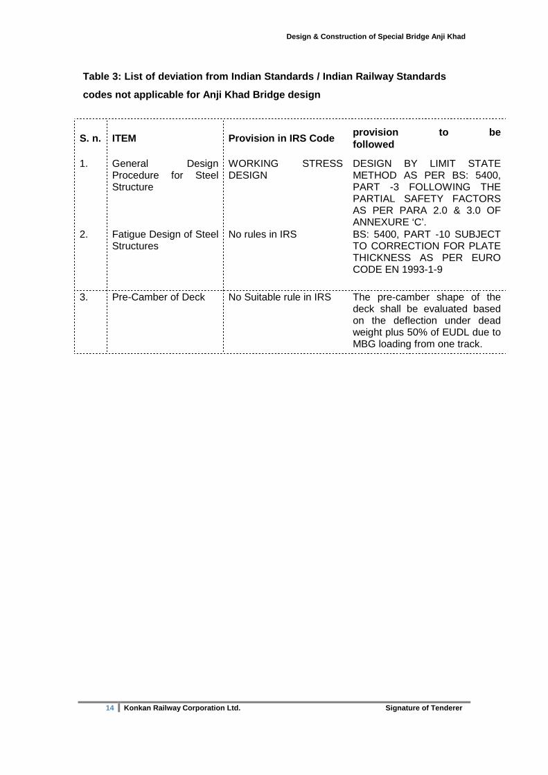
Table 3: List of deviation from Indian Standards / Indian Railway Standards
codes not applicable for Anji Khad Bridge design
S. n. ITEM Provision in IRS Code provision to be followed
1.
General Design Procedure for Steel Structure
WORKING STRESS DESIGN
DESIGN BY LIMIT STATE METHOD AS PER BS: 5400, PART -3 FOLLOWING THE PARTIAL SAFETY FACTORS AS PER PARA 2.0 & 3.0 OF ANNEXURE ‘C’.
2.
Fatigue Design of Steel Structures
No rules in IRS BS: 5400, PART -10 SUBJECT TO CORRECTION FOR PLATE THICKNESS AS PER EURO CODE EN 1993-1-9
3.
Pre-Camber of Deck
No Suitable rule in IRS The pre-camber shape of the deck shall be evaluated based on the deflection under dead weight plus 50% of EUDL due to MBG loading from one track.

Design & Construction of Special Bridge Anji Khad
15 Konkan Railway Corporation Ltd. Signature of Tenderer
Annexure ‘B’
Table 1 - General and Material
S. n. Item Description
1 Bearing Spherical knuckle Bearing
2 Design Life 120 Years
3 Design Speed 100 KMPH
4 Steel IS:2062- 1999 or latest, Grade C, normalized or equivalent
5 Main Grade of Concrete (i) Foundation (ii) Piers
M 35 M 35
6 Reinforcement Bars As per IS:1786 7 Post tensioning Bar ASTMA 722 (Type-II) 8 Pre-stressing Strands As per IS: 14268 Class- II. 9 Bolts, Nuts and Washers
BS: 4395 for HSFG bolts - minimum dia 24mm IS: 4000/3757/6623/6649 for high strength bolts/nuts & washers.
Table 2 - LOADS
S. n. Item Description
Design loads : All the loading should be taken as per IRS MBG, 1987.
1 Dead load: (DL) (a) Plain Concrete (b) Steel (c) RCC
24.0 KN/m3 As per IS: 456 78.5 KN/m3 25.0 KN/m3
2 Super Imposed Dead Load: (SDL) (a) Track (b) Utilities
9.0 KN/m 5.0 KN/m 14 KN/m
3 Live Load: (LL) Centrifugal Force Eccentricity of Track Raking Force
IRS, MBG: 1987 IRS Bridge Rules, clause 2.5 100 mm (IRS Bridge Rules, clause 2.5) IRS Bridge Rules, clause 2.9
4 Dynamic Augment : (CDA) As per clause 2.4 of IRS Bridge Rules for deck and piers and columns of arch. No CDA to be taken for Arch.
5 Braking and Acceleration Force: (BA)
As per IRS Bridge Rules

Design & Construction of Special Bridge Anji Khad
16 Konkan Railway Corporation Ltd. Signature of Tenderer
6 Temperature Effect (A) Uniform Temperature: (T) (i) Mean Temperature (ii) Co-eff. Of Thermal
Expansion Steel & RCC (iii) Variation of effective
temperature.
(B) Differential Temperature: (DT)
(i) Differential temperature-Lateral
(ii) Safety factor for expansion displacement.
200 C 1.17x 10⁻⁵/ 0C (Bridge Rules, clause 2.62) 400 C to - 100 C BS: 5400 Part.-II ± 50 C 1.2
7 In Service Wind Load: (SW) Corresponding to max. wind pressure of 150 kg/m2 at deck level (based on 3 second gust). The height of rolling stock to be adopted for arriving at SW load shall be 4.725m. Total wind load for the deck is computed as the sum of wind loads of the deck and the train using the appropriate force coefficients for both. For the deck, the force coefficients are based on wind tunnel test results. For the train, horizontal force coefficient is based on IS: 875 and equals to 1.0.
8 Wind forces: (W)
As per IS: 875 for 120 Yr return period. The final value of equivalent static wind load shall be determined after analyzing results of wind tunnel test.
9 Seismic Forces: (EQ) a) Structural Damping. (i) Steel (ii) Concrete b) LL during Seismic conditions c) Response spectra for
horizontal and vertical Earthquake acceleration
d) Combination of effects
As per the report of site specific spectral studies carried out by IIT, Roorkee (Annexure D), and IS: 1893 part-1, 2002. 2% 5% As per IRS Bridge Rules As per IIT, Roorkee report (Annexure D) 30% rule
10 Derailment Load: (DLR) 3. Load Value 4. Dispersion 5. Impact
IRS Bridge Rules- Load values shall correspond to those laid down under ‘Bridges with Guard rails’ of Appendix IX of IRS Bridge Rules No Dispersion Without impact
11 Snow Load No Snow load to be taken.
12 Differential settlement: (DS) (i) Pier Foundations (ii) Arch Foundations
20mm vertical 20mm vertical & 20mm horizontal or settlement determined at site with Plate Load Test whichever is more

Design & Construction of Special Bridge Anji Khad
17 Konkan Railway Corporation Ltd. Signature of Tenderer
(iii) Rotational Stiffness of Arch Abutment
Upper limit - Rigid Lower limit - 90% of the arch bending moment
13 Forces due to LWR: (LWR) As per para 2.4.7 of DBN
14 Blast Load: (B) The partial load factor for blast load shall be γfL=1.0.
1. The bridge shall be designed for following scenarios of blast taking place at the bridge.
(i) A blast of 100 kg (TNT equivalent) at ground level at a distance of 20 m from the face of piers/abutment
(ii) A contact blast of 40 kg (TNT equivalent) occurring at any point on deck plate, with the train running on the track on bridge deck.
Note: The arch trusses shall not be damaged and no deck span shall collapse under the above scenarios. It should be possible to restore the bridge to its original serviceability requirement in reasonable time and cost. Suitable sacrificial arrangement shall be provided to ensure no damage to main I-girders of deck.
2. The overpressure, time duration, specific impulse and dynamic pressure for various probable locations of the blast over the deck shall be calculated from appropriate references such as IS: 4991 and the book “Explosion Hazards” by Baker etc.
15 Frictional resistance at Bearings: (FR)
As per BS: 5400, in conjunction with other concomitant horizontal forces
Table 3 - Characteristic Strength and Partial Safet y Factor for Material
1 2 3
Steel Composite Concrete
BS: 5400 Pt.3 Table –2 BS: 5400 Pt.5 Table –1 IRS Concrete Bridge Code
Table 4 - Fatigue Considerations
1 Fatigue Design Method BS: 5400 for 120 years design life. The influence of plate thickness in fatigue design shall be considered in terms of EN 1993-1-9.
2 Load Spectra
As per Table 6 and Table 7 of Annexure ‘B’
3 Traffic Load Classification Mixed Traffic Lines with Light Traffic (40 GMT) of Table- 6 of this Annexure.

Design & Construction of Special Bridge Anji Khad
18 Konkan Railway Corporation Ltd. Signature of Tenderer
Table 5 - Other Features of Design Basis of Anji Khad Bridge
1 Structural Deformation Limit (i) Vertical
Deflection (ii) Lateral
displacement
All the structural deformation limits prescribed in UIC 776-3R shall be complied with wind pressure of 150 kg/sqm, considering the least favourable case with one tracks loaded and other forces as given in Table – 2 of Annexure ‘B’ and the load combinations given in para 2.0& 3.0 of Annexure ‘C’ for service conditions. The ratio of span to maximum vertical deflection shall not be less than 400 given in Table 4 of UIC 776-3R for the case of one or two adjacent decks case for speed range 1 for high quality passenger line. The horizontal deformation of bridge deck should not cause a horizontal change of angle at a free end exceeding 0.0035 radian, nor a change of curvature radius of less than 3500 m for several adjacent decks as given in Table 2 of UIC 776- 3R for speed range 1.
2 Structural redundancy of major elements
Two aspects viz. (i) lower level of operation and (ii) prevention of collapse of bridge will be considered as under.
i) Lower Level of Operation
The structural redundancy of the system will be assessed by removing critical bridge elements, only one at a time with γm=1. One train passing at low speed of 30 kmph will be considered. Single elements (one at a time) of arch will be removed from the structural model. These elements are, a) One chord of the arch between the connecting members of arches. a) There are two rows of piers and diagonal members, which
connect the deck and the arch. One diagonal member of one of the rows shall be removed at a time.
b) One connection of cross beam, which supports spandrel column, with the arch ribs.
c) One diagonal bracing of diagonal member / spandrel column.
The wind loads shall be considered for a return period of 5 years. Structural deformations at lower level of operation need not be checked this being exceptional case, however the bridge shall be structurally safe under all load combinations mentioned in para 2.4 of annexure C. Necessary adjustment in track parameters if required shall be made by Railway before allowing operations at lower level.

Design & Construction of Special Bridge Anji Khad
19 Konkan Railway Corporation Ltd. Signature of Tenderer
ii) Prevention of Collapse of bridge
For the effect of collapse of piers, only one pier at a time will be checked as per load combination 11 of Table 3.0 of Annexure ‘C’ with γm=1. The bridge shall be checked against collapse by using ULS method with factored dead loads and without any live load on the bridge under the following condition: Collapse of one pier / vertical member/diagonal member
3 Wind / Seismic Forces during Erection
The wind loads shall be considered for a return period of 5 years and earthquake forces shall be 50% of in-service condition.
4 Track Twist As per Para 5 of UIC 776-3R
5 Bending and vertical movement of the track
As per provision of UIC 776-3R ( Table 1: for the case corresponding to direct track fastening on both sides)

Design & Construction of Special Bridge Anji Khad
20 Konkan Railway Corporation Ltd. Signature of Tenderer
Table 6: Traffic details of Broad Gauge train (fati gue load model for MBG loading)
Type of Train
Train N
o.
Train Composition
Weight per Train (t)
GMT per Train
Class of Traffic
Heavy Freight Traffic (100 GMT)
Mixed Traffic Lines with Heavy Traffic (70 GMT)
Sub-urban Traffic (60 GMT)
Mixed Traffic Lines with Light Traffic (40 GMT)
No. of Trains
GMT No. of Trains
GMT No. of Trains
GMT No. of Trains
GMT
Passenger Trains
1 2 3 4
1+15 2+22 2+26 AC EMU 12
900 1400 1700 700
0.33 0.51 0.62 0.26
3 2 - -
1.0 1.0 - -
6 10 14 -
2.0 5.1 8.7 -
- 5 5 200
- 2.6 3.1 52.0
5 5 - -
1.7 2.6 - -
Freight Trains loaded
5 6 7 8
1+75-4 2+40 BOX 2+55 BOXN 2(2+55 BOXN)
3200 3600 5100 10300
1.17 1.31 1.86 3.76
2 2 10 20
2.3 2.6 18.6 75.2
2 - 4 12
2.3 - 7.4 45.1
- - - -
- - - -
2 5 10 2
2.3 6.5 18.6 7.5
Freight Trains empty
9 10
1+75-4 Wheeler 2+40 BOX
1100 1300
0.40 0.47
- -
- -
- -
- -
- -
- -
2 2
0.8 0.9
Total 39 100.7 48 70.6 210 57.7 33 40.9
Note: In the design of Anji Khad Bridge the Class of Traffic will be “Mixed Traffic Lines with Light Traffic (40 GMT).

Design & Construction of Special Bridge Anji Khad
21 Konkan Railway Corporation Ltd. Signature of Tenderer
Table 7: Description of Broad Gauge Trains
1950
297 0
2050
556 0
1950
2 050
5 279
2896
2896
4618
2309
2896
2896
1 - 6 x 25 t 15 - 4 x 13.0 t = (900.0 t)TOTAL = 930.0 t(1) PASSENGER TRAIN-1
2 050
(2) PASSENGER TRAIN-22 - 6 x 25 t
2050
297 0
1950
556 0
1950
5940
2050
22 - 4 x 13.0 t
5279
TOTAL = 1444.0 t = (1400.0 t)
1950
5560
1950
2050
2896
2896
4618
2896
2896
2 309
1950
(3) PASSENGER TRAIN (A.C.) -3
297 0
2050
5560
1950
556 0
2 050
2 - 6 x 25 t
1950
2050
5940
2 - 4 x 16.25 t (A.C.)
2050
1950
5279
2896
4618
2896
2896
2896
4618
24 - 4 x 13.0 t
2896
4618
2896
2896
2309
TOTAL = 1678.0 t = (1700.0 t)
(4) PASSENGER TRAIN 4 (EMU)
2896
2082
1 - 4 x 13.0 tTOTAL = 736.0 t
= (700.0 t)
4 SUCH UNITS FORM ONE TRAIN
2896
3995
2896
2896
2896
3995
2896
2082
1 - 4 x 20.0 t 1 - 4 x 13.0 t
(5) GOODS TRAIN LOADED - 1
2050
2970
1 - 6 x 25.0 tTOTAL = 3195.0 t
= (3200.0 t)75 - 2 x 20.3 T
1950
5560
1950
2050
4931
4900
3922
4900
3922
3922
4900
1961
Table 5.7 : Description of Board Gauge Trains
Train type CompositionTotal
Diagram
Type - 1 1L + 15 ICF 348.676 930
Type - 2 2L + 22 ICF 524.255 1444
Type - 3 2L + 26 613.443 1678
Type - 4 EMU 12 254.764 736
Type - 5 1L + 75 - 4 676.219 3195
(Non AC)
(Non AC)
Wheeler
(m)

Design & Construction of Special Bridge Anji Khad
22 Konkan Railway Corporation Ltd. Signature of Tenderer
(6) GOODS TRAIN LOADED - 2
Train type CompositionTotal
Diagram
Type - 6 2L + 40 BOX 583.726 3551
Type - 7 624.151 5140
Type - 8 1252.365 10280
Type - 9 676.219 1132.5
Type - 10 2L + 40 BOX 583.725 130859
40
1950
2 - 6 x 25.0 t
2970
2050
5560
205 0
1950
= (3600.0 t)TOTAL = 3551.0 t
2050
1950
5560
1950
2050
2000
6800
2000
2929
2000
2000
40 - 4 x 20.32 t
2 - 6 x 25.0 t(7) GOODS TRAIN LOADED - 3
1950
2970
2050
5560
205 0
1950
= (5100.0 t)TOTAL = 5140.0 t
55 - 4 x 22.0 t
5560
1950
2050
5940
2050
1950
4524
2000
2000
2189
2000
2000
(8) GOODS TRAIN LOADED - 4
2 - 6 x 25.0 t + 55 - 4 x 22.0 t
1950
2970
2050
5560
1950
205 0
TOTAL = 10280.0 t = (10300.0 t)
2000
5560
2050
5940
1950
2050
1950
2000
2000
4524
2189
2000
2 SUCH TRAINS
205 0
(9) GOODS TRAIN EMPTY - 11 - 6 x 25.0 t
2050
2970
5560
1950
1950
TOTAL = 1132.5 t = (1100.0 t)
4931
75 - 2 x 6.55 t
4900
392 2
4900
3922
3922
4900
1961
(10) GOODS TRAIN EMPTY = (1300.0 t)
TOTAL = 1308.0 t
205 0
2050
2970
5560
1950
1950
5560
5940
2050
1950
2050
1950
40 - 4 x 6.3 t
2000
6800
2000
2929
2000
2000
2 - 6 x 25.0 t
1. ALL DIMENSIONS IN MILLIMETRES.2. FIGURES IN BRACKETS ARE ROUNDED FIGURES.
NOTE :-
(m)
Type
Type
(Empty)
(Empty)

Design & Construction of Special Bridge Anji Khad
23
Konkan Railway Corporation Ltd. Signature of Tenderer
Annexure C LOAD COMBINATION AND PARTIAL LOAD FACTORS
1.0 Legends for Characteristic Loads (Q k) is given below for better readability
DL Dead Loads
SDL Superimposed Dead Loads
LL Vertical Live Loads
BA Braking and Acceleration Forces
T Uniform Temperature
DT Temperature Gradient
DS Differential Settlement
W Design Wind Load
SW Service Wind Load corresponding to max. wind pressure at
deck level of 150 kg/m2 (based on 3 second gust)
EQ Earthquake Load
B Blast Load
LWR Effects due to Long Welded Rails
DLR Derailment load
ER Loads during erection / construction stage
FR Friction Resistance at Bearings
2.0 Steel structure:
Various Load combinations in the table above are as below: (4 stages)
2.1 In service stage load combinations
Combination 1: DL + SDL + LL + BA + DS+FR Combination 2: DL + SDL + LL + BA + DS+SW +FR Combination 3: DL + SDL + LL + BA + DS +T + DT + LWR+FR Combination 4: DL + SDL + DS + W+FR Combination 5: DL + SDL + DS + EQ+FR Combination 6: DL + SDL +LL+BA+ DS +EQ+FR Combination 7: DL + SDL + LL + BA + DS + DLR+FR Combination 8: DL + SDL +LL + BA + B+FR
2.2 Erection stage load combinations
Combination 9: DL + SDL + W + ER
Combination 10:DL + SDL + EQ + ER (only 3 critical stages of erection to be analyzed.)
2.3 Collapse of pier stage load combination: Combination: 11 DL+SDL
2.4 Lower level of operation load combinations All combinations similar to in service stage load combination 1A to 3 B with reduced loads as per Item 2 of Table 5 of Annexure ‘B’.
24 Konkan Railway Corporation Ltd. Signature of Tenderer
Design & Construction of Special Bridge Anji Khad
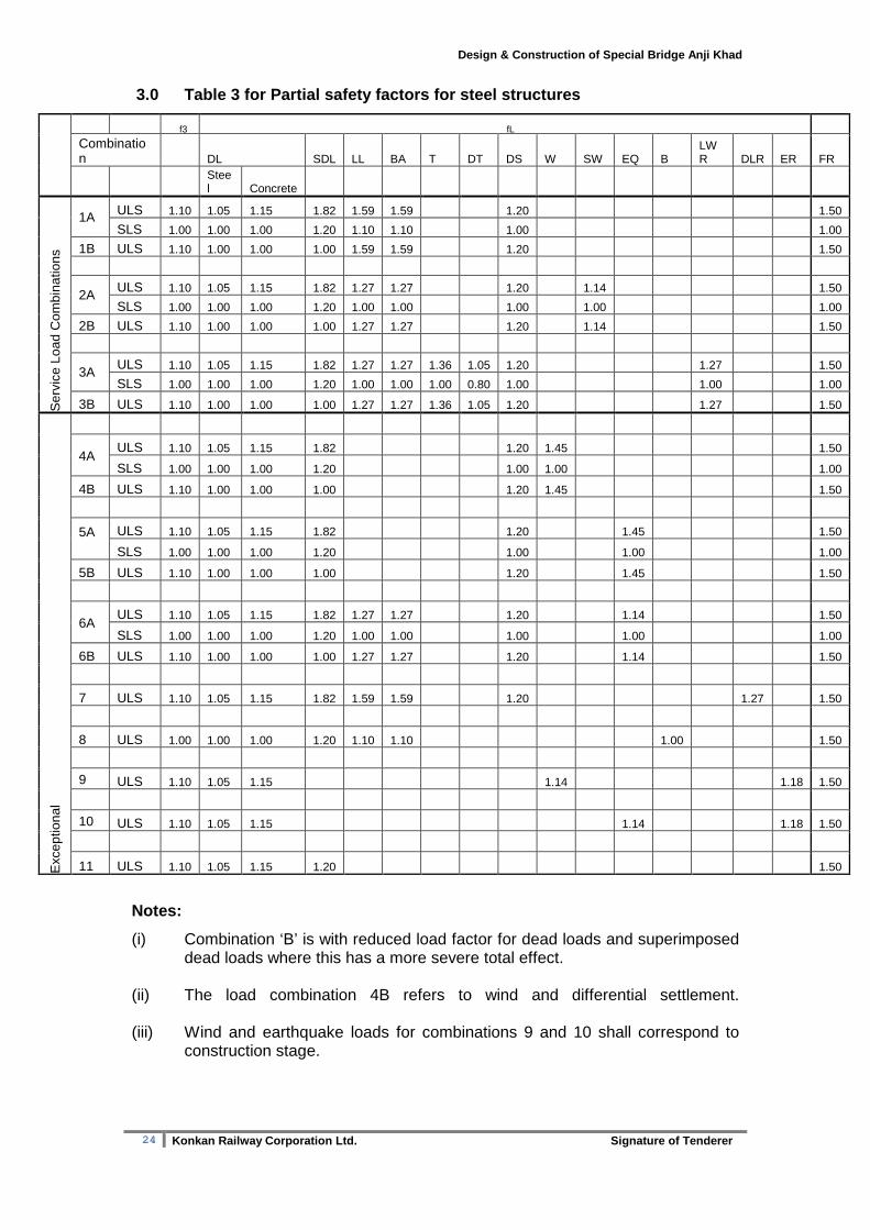
3.0 Table 3 for Partial safety factors for steel st ructures
�f3 �fL
Combination DL SDL LL BA T DT DS W SW EQ B
LWR DLR ER FR
Steel Concrete
Ser
vice
Loa
d C
ombi
natio
ns
1A ULS 1.10 1.05 1.15 1.82 1.59 1.59 1.20 1.50
SLS 1.00 1.00 1.00 1.20 1.10 1.10 1.00 1.00
1B ULS 1.10 1.00 1.00 1.00 1.59 1.59 1.20 1.50
2A ULS 1.10 1.05 1.15 1.82 1.27 1.27 1.20 1.14 1.50
SLS 1.00 1.00 1.00 1.20 1.00 1.00 1.00 1.00 1.00
2B ULS 1.10 1.00 1.00 1.00 1.27 1.27 1.20 1.14 1.50
3A ULS 1.10 1.05 1.15 1.82 1.27 1.27 1.36 1.05 1.20 1.27 1.50
SLS 1.00 1.00 1.00 1.20 1.00 1.00 1.00 0.80 1.00 1.00 1.00
3B ULS 1.10 1.00 1.00 1.00 1.27 1.27 1.36 1.05 1.20 1.27 1.50
Exc
eptio
nal
4A ULS 1.10 1.05 1.15 1.82 1.20 1.45 1.50
SLS 1.00 1.00 1.00 1.20 1.00 1.00 1.00
4B ULS 1.10 1.00 1.00 1.00 1.20 1.45 1.50
5A
ULS 1.10 1.05 1.15 1.82 1.20 1.45 1.50
SLS 1.00 1.00 1.00 1.20 1.00 1.00 1.00
5B ULS 1.10 1.00 1.00 1.00 1.20 1.45 1.50
6A ULS 1.10 1.05 1.15 1.82 1.27 1.27 1.20 1.14 1.50
SLS 1.00 1.00 1.00 1.20 1.00 1.00 1.00 1.00 1.00
6B ULS 1.10 1.00 1.00 1.00 1.27 1.27 1.20 1.14 1.50
7 ULS 1.10 1.05 1.15 1.82 1.59 1.59 1.20 1.27 1.50
8 ULS 1.00 1.00 1.00 1.20 1.10 1.10 1.00 1.50
9 ULS 1.10 1.05 1.15 1.14 1.18 1.50
10 ULS 1.10 1.05 1.15 1.14 1.18 1.50
11 ULS 1.10 1.05 1.15 1.20 1.50
Notes:
(i) Combination ‘B’ is with reduced load factor for dead loads and superimposed dead loads where this has a more severe total effect.
(ii) The load combination 4B refers to wind and differential settlement.
(iii) Wind and earthquake loads for combinations 9 and 10 shall correspond to
construction stage.

25 Konkan Railway Corporation Ltd. Signature of Tenderer
Design & Construction of Special Bridge Anji Khad
4.0 Table for Partial safety factors for Reinforced concrete structures:
INDIAN RAILWAY STANDARD CODE OF PRACTICE FOR PLAIN REINFORCED AND PRESTRESSED CONCRETE FOR GENERAL BRIDGE CONSTGRUCTION (CONCRETE BRIDGE CODE)TABLE 12 LOADS TO BE TAKEN IN EACH COMBINATION WITH APPROPRI ATE γfL
(Clauses 11.2 and 11.3) LOAD LIMIT
STATE γfL TO BE CONSIDERED IN COMBINATION
1 2 3 4 5 Dead weight of concrete ULS
SLS 1.25 1.00
1.25 1.00
1.25 1.00
1.25 1.00
1.25 1.00
Superimposed dead load ULS SLS
2.00 1.20
2.00 1.20
2.00 1.20
2.00 1.20
2.00 1.20
Wind During erection ULS SLS
- -
1.25 1.00
- -
- -
- -
With dead and superimposed dead loads only and for members primarily resisting wind loads.
ULS SLS
- -
1.60 1.00
- -
- -
- -
With dead plus superimposed dead plus other appropriate combination 2 loads.
ULS SLS
- -
1.25 1.00
- -
- -
- -
Relieving effect of wind ULS SLS
- -
1.00 1.00
- -
- -
- -
During erection. ULS SLS
- -
1.25 1.00
- -
- -
- -
Earth quake
With dead and superimposed dead loads only.
ULS SLS
- -
1.60 1.00
- -
- -
- -
With dead plus superimposed dead plus other appropriate combination 2 loads.
ULS SLS
- -
1.25 1.00
- -
- -
- -
Tempe rapture
Restraint against movement except frictional.
ULS SLS
- -
- -
1.50 1.00
- -
- -
Frictional restraint. ULS SLS
- -
- -
- -
1.50 1.00
- -
Differential temperature effect. ULS SLS
- -
- -
1.15 0.80
- -
- -
Differential settlement ULS SLS
As specified by Engineer
Earth pressure
Fill retained and or live load surcharge relieving effect.
ULS SLS
1.70 1.00
1.70 1.00
1.70 1.00
1.70 1.00
- -
Relieving effect. ULS
1.00 1.00 1.00 1.00 - -
Erection temporary loads (when being considered).
ULS - 1.30 1.30 - -
Live load on foot path ULS SLS
1.50 1.00
1.25 1.00
1.25 1.00
- -
- -
Live load ULS SLS
1.75 1.10
1.40 1.00
1.40 1.00
- -
- -
Derailment loads. SLS (As specified by Bridge Rules for combination 5 only)
NOTE 1 – ULS: Ultimate limit state SLS: Serviceab ility limit state NOTE 2 – Superimposed dead load shall include dead load of ballast track, ballast retainer, precast footpath, wearing course, handrails, utility services, kerbs etc. NOTE 3 – Wind and earthquake loads shall not be ass umed to be acting simultaneously. NOTE 4 – Live load shall also include dynamic effec t, forces due to curvature exerted on track, longitudinal forces, br aking forces and forces on parapets.

26 Konkan Railway Corporation Ltd. Signature of Tenderer
Design & Construction of Special Bridge Anji Khad
Annexure D
Extract of SITE-SPECIFIC DESIGN EARTHQUAKE PARAMETERS
FOR ANJIKHAND RAILWAY BRIDGE, J. & K.
1.0 INTRODUCTION
The Konkan Railway Corporation Ltd. (KRCL), Navi Mumbai is in process of
construction of Anjikhand Railway Bridge in J. & K. The latitude and longitude of the
bridge site are 33o 04’ N and 74o 54’ E. The site-specific earthquake parameter
studies for seismic design of the structure of the Anjikhand Railway Bridge were
referred to Department of Earthquake Engineering, Indian Institute of Technology,
Roorkee by Konkan Railway Corporation Ltd. Accordingly, the Department has taken
up the studies for site-specific earthquake parameters for the site.
1.1 The site lies in seismic zone V as per the seismic zoning map of India
incorporated in Indian Standard Criteria for Earthquake Resistant Design of
Structures (IS : 1893 (Part 1): 2002). The probable intensity of earthquake in
seismic zone V corresponds to Comprehensive Intensity Scale (MSK-64) IX and
structures designed as per recommended design parameters for this zone would
generally prevent loss of human life and only repairable damage could occur.
However, the recommended design parameters in IS : 1893(Part 1): 2002 are for
preliminary design of important structures and to ensure full functioning of important
lifeline facilities in the event of an earthquake it is desirable to carryout site specific
studies for final design of important structures.
1.2 The present report contains our final recommendations for the site in terms of
the peak ground acceleration values and design spectra for various damping values
for maximum considered earthquake and design basis earthquake for the site. The
recommendations are based on the studies carried out related to the regional
geology, local geology around the site, earthquake occurrences in the region around
the site and the seismotectonic setup of the area.
27 Konkan Railway Corporation Ltd. Signature of Tenderer
Design & Construction of Special Bridge Anji Khad
2.0 REGIONAL GEOLOGY AND TECTONICS OF THE REGION 2.1 The Anjikhad bridge project site in Jammu and Kashmir is located just north
of Jwalamukhi Thrust and south of MBT. Beside MBT the Jwalamukhi Thrust
towards south is another prominent thrust classified as neotectonic feature by GSI
(2000). Geology of the project site is represented by dolomitic limestone belonging to
Siwalik Himalayas. Quite a few tectonic features are present around the site and a 60
X 60 area (Fig.1) bounded by latitudes 300N and 360N and longitudes 720E and 780E
around the site has been considered for the study of regional geotectonic set up of
the region and is described below.
2.2 The study area is represented by two distinct domains. Towards northeast rock
sequence of the Himalayan orogenic Belt is exposed, while the Quaternary alluvial
deposits of the Indo-Gangetic Plains cover the remaining area. The litho-tectonic
assemblages of the Himalayan Orogenic Belt belong to poorly metamorphosed litho-
unit of the Tethyan sequence, high and low grade assemblages and Lesser
Himalayan belt, respectively along with granitoids and basic volcanics. Cover rocks
of the frontal belt occupy the southern fringe of the Himalayan belt. Further south,
the Quaternary cover is represented by alluvial fill along the foredeep.
2.3 The northernmost prominent tectonic feature present in the study area is
extensive Karakoram Fault which has affected the region with a huge dextral offset
and is traceable towards northwest through the Shyok Suture to the Pamir. Three
splays curving westward through the central Pamir; the Tangkul, Murghab and
Karasu faults accommodate the movement in the central part of the Karakoram Fault
have (Searle, 1996). This fault controls the alignment of Siachen glacier and the
Nubra-Shyok valley.
2.4 The Shyok Suture Zone with a NW-SE trend represents an oceanic suture
(Gansser, 1977) or a relic of back-arc basin (Sharma, 1991). This suture zone is
located far north of project site and show huge displacement affected by the strike
slip movement of the rock masses of the region along the Karakoram fault. The
tectonic evolution of this suture zone is believed to have resulted from collision of the
Kohistan island arc with Asian margin. The Kohistan and Asian plate rocks are
separated by a series of brittle faults called the Main Karakoram Fault. The
sedimentary, volcanic and plutonic rocks of the Shyok suture zone are intensely
deformed and occur as tectonic slices between the Ladakh and Karakoram
batholiths. The major tectonic slices of this suture zone are, Khardung Formation;
Hundri Formation; Shyok Volcanics; Saltoro Molasse, Shyok Ophiolitic Melange and
Tirit Granitoids.
28 Konkan Railway Corporation Ltd. Signature of Tenderer
Design & Construction of Special Bridge Anji Khad
2.5 The Main Mantle Thrust (MMT) marks the collision of the Asian plate and
Kohistan which began with initial tectonic thickening and high pressure, high
temperature metamorphism, followed by post metamorphic southward-directed
thrusting as rocks of the Asian plate were thrust over Kohistan. The MMT is
represented by thick zone of highly disrupted mélange along with abundant mylonite
affected by set of brittle normal faults (Chamberlain and Zeitler, 1996). The geology
of the northern margin of the Indian plate is remarkably uniform along hundreds of
kilometer of the MMT. The rocks in the Indian plate consist of low to high-grade
calcareous schists, minor marbles and amphibolites, and basement gneisses
affected by thrusting.
2.6 Part of the Indus Suture Zone (ISZ) is exposed on the NE corner of the study
area. This zone marks the boundary between the Indian and Tibetan plates and
south of this; litho-units of the main Himalayan belt are exposed. Within the
Himalayan belt, the northernmost conspicuous structural element is the Main Central
Thrust (MCT). From Manali towards east throughout the entire Himalaya almost
upto the eastern syntaxis, this is considered as one of the most important tectonic
surfaces. However, northwest of Manali it is not clearly discernible. This Lesser
Himalayan belt is separated from the Frontal Belt (comprising the Siwalik sequence)
by the Main Boundary Thrust (MBT). This thrust has brought the Lower Tertiaries in
juxtaposition against the Siwalik Group. The Siwalik is mainly arenaceous facies and
represents a molasse deposit (predominantly sandstone and boulder beds), which
was deposited in a foredeep at the end of the Tertiary orogeny in Himalaya. From
NW to SE the MBT that separates the Sirmur belt (Paleogene) from the Siwalik belt,
is tectonically overlapped by diverse and even structurally higher thrust sheets. The
MBT is not a single thrust plane and the configuration is produced on the surface by
an overlapping of thrust sheets.
2.7 The Main Frontal Thrust (MFT) that has its surface manifestations only at a
few places marks the southern limit of the Frontal Belt. Within MBT and MFT the
fold belt is traversed by several subsidiary thrusts some of which have considerable
spatial extent viz. Jwalamukhi Thrust and Drang Thrust. Evidences of neotectonic
activity have been documented at several places along MBT and in western parts of
Jwalamukhi Thrust. The Frontal Belt package is affected by several regional scale
folds, of which Mastgarh and Paror anticlinal axial traces are traceable for
considerable distances (Srikantia and Bhargava, 1998).

29 Konkan Railway Corporation Ltd. Signature of Tenderer
Design & Construction of Special Bridge Anji Khad
2.8 Except Siwalik Formations in the Himalayan tectonic belt, all other geological
formations have suffered extensive tectonic movement and the rock formations were
subjected to displacement from its original place of deposition. This transportation
was caused due to large scale thrusting of various geological formations due to
intense operative compressional tectonic activity in geological past resulting in
numerous nappe structures.
2.9 In the area, north of the project site falling in J. & K., the main mountain
range is called the Pir Panjal range. This range is composed of highly compressed
and altered rocks of various ages forming high mountains. North of this a saucer
shaped valley with a length of 135 km and width of 40 km is situated which is known
as Valley of Kashmir and is bounded by the Laddakh Himalayas towards north. In
this region the rocks units as well as structural features trend in arcuate fashion with
southwestward concavity and in the intervening areas the concavity is in the opposite
direction. According to Krishna Rao and Rao (1979) the three prominent tectonic
units recognizable in this area are : (i) the broad Autochthonous Zone, exposing
chiefly the Neogene sediments with local inliers of Eocene and Pre-Tertiary
limestone with a series of prominent anticlines and synclines and a number of strike
faults; (ii) the narrow parautochthon zone, between the Murree and Panjal thrusts,
consists of upper Carboniferous-Permian sediments, volcanics and the Eocene
outliers; and (iii) the allochthonous zone, thrust over the parautochthon, consists of
rocks of Salkhala/Dogra units with granitised portions within folded synclines of
Paleozoic, Mesozoic and Triassic sediments.
2.10 Wadia (1966) considered the two concurrent thrusts on the southern part of
the Himalayas as the most important features of the region delimiting the
autochthonous belt. Out of these two thrusts the Panjal Thrust is considered most
significant involving large-scale displacements. The Murree thrust shows greater
vertical displacements and steeper inclinations with persistence over the whole
region. The autochthonous belt between the two thrusts consists of a series of
inverted folds of Eocene rocks enclosing Permo-Carboniferous Panjal volcanics and
Triassic formations. Panjal volcanics (traps) is underlain by Tanawals. The contact
between the Murree and Tanawals named as Panjal thrust. In Jammu foothills two
major structural units can be recognized and these are: (i) the Suruin-Mastgarh
anticline bordering the plains, and (ii) the folded and faulted belt to the northeast of
Suruin-Mastgarh antclinal unit (Karunakaran and Rao, 1979).

30 Konkan Railway Corporation Ltd. Signature of Tenderer
Design & Construction of Special Bridge Anji Khad
2.11 In Himachal Pradesh, the Jutogh rocks constitute synformal outliers around
Simla and the Chor mountain. In both these places the Jutogh rocks overlie rocks of
Chail Formation. The Salkhala metasedimentaries occur as a tectonic unit younger
than the Jutogh Nappe. Salkhala Formation extends from south of Rampur, forming
the base of Pandoh syncline and extending to east of Mandi, where the Salkhala
thrust appears to overlap the Jutogh thrust and to continue further NW into Kashmir
(Srikantia and Bhargava, 1998). Between Mandi and Kulu the Salkhala
metasedimentaries have a wide extent and in the centre of these, there exists a
syncline of sedimentary rocks. The Chail Series comprises of number of
recrystallized quartzite horizon, underlies the Jutogh klippen of Simla and Chor area.
2.12 There is more or less continuous structural zone of high grade gneisses and
migmatites with metasedimentary intercalations referred to as the Central Crystalline
Zone. This zone is strongly deformed with ductile and, at places, brittle shearing. The
structural pattern in the crystalline zone is controlled by large bodies of competent
granite-gneiss units and less competent metasediments, which developed into
nappes. The Kulu nappe is a highly tectonised thrust sheet with the development of
mylonite along the sole of the nappe. All rocks of the nappe have been affected by
ductile shearing. The thrust that has brought the Kulu nappe over the Lesser
Himalayan tectonic belt is the most outstanding tectonic feature in Himachal
Himalaya and is equivalent of the MCT (Srikantia, 1988). The Kulu nappe sweeps
over the Larji-Rampur-Wangtu structural belt and comes to rest over the Shali-Simla
structural belt. The Jutogh belt is the most southerly-transgressed nappe and the
Jutogh delineates the base of this thrust, tectonicaly overlapping the Jaunsar
structural belt. The Salkhala nappe, which is folded as a major NW-SE trending
synform, is noticed mainly in contact with the Kulu nappe along a tectonic
discontinuity.
2.13 The Sirmur structural belt which is largely controlled by basement structures,
extends from Dharmsala in NW to Sirmuri Tal in SE comprises Subathu-Dagshai-
Kasauli of Lower Siwalik in the Mandi reentrant section. The Shali structural belt is a
parautochthonous belt, tectonically bounded on the southwest by the Paleogene
Sirmur belt. It actually forms a long sigmoidal shaped, reentrant controlled structural
belt mapped in the Himachal Himalaya from Ravi in NW to Nag Tikar in SE
(Srikantia and Sharma, 1976). The reentrant marks zones of intense thrusting
caused by Peninsular basement projections which have exercised parental control
on the sediment cover. The Simla Group is basically a cover over the Shali Group,
Sundernagar Group and Mandi-Darla Volcanics and therefore, it is closely

31 Konkan Railway Corporation Ltd. Signature of Tenderer
Design & Construction of Special Bridge Anji Khad
intertwined with the Shali-Sundernagar in its structural evolution. The Larji-Rampur-
Wangtu window consists of a complex sedimentary and igneous rocks framed by the
Kulu thrust sheet are a remarkable structural feature in the Lesser Himalayan belt.
2.14 The Siwalik belt occupying a sprawling foothill zone consist of outcrops of
Tertiary rocks in several folded and faulted strips. The Siwalik present a picture of
folded structural belt with broad synclines alternating with steep, often faulted,
narrow asymmetric anticlines. The axial planes as well as the strike faults and
thrusts on their limbs are steep at the surface and dip more gently northwards at
depth (Srikantia and Bhargava, 1998).
2.15 In addition to the structural discontinuities sub-parallel to the Himalayan trend,
there are number of faults/lineaments transverse to this fold-thrust belt. The
Sundernagar Fault (also known as Manali Fault) is a dextral transverse structure,
which extends from Higher Himalaya to the Frontal Belt. This fault is considered to
have caused the swing of the Frontal Belt from NW-SE to N-S. The Ropar Fault,
occurring northwest of Chandigarh is postulated to be the southward continuation of
the Sundernagar Fault. A fault with similar trend and sense of movement is
identified in the southeastern side of Chandigarh. Further east, the Yamuna Tear
displays sinistral sense of movement. All these faults exhibit neotectonic activity. Of
the several transverse faults of limited surface extension, Kishtwar Fault (also known
as Suru Fault) is the most prominent one. The basement contour pattern reveals that
the Delhi-Sargodha Ridge extends in.the southern part of this area (GSI, 2000). The
Sahaspur Low flanks this basement high towards north. The basement contours
have a general NW-SE trend except in the vicinity of Mahendragarh-Dehradun Fault,
where the contour pattern reflects the presence of a basement high.
2.16 The N-S trending Jhelum fault among these is most extensively present. It is
a left lateral wrench fault, which separated Peshwar Basin from the Kashmir Basin
(GSI, 2000). Towards south of this fault, the Mangla fault crosses it with right lateral
wrench movement along the fault. The Tarbela fault, located within the Peshwar
Basin is sub-parallel to the Jhelum fault. Another alike fault is Shinkiari Fault
developed along the eastern margin of the Peshwar Basin. These faults cut across
the alluvium and exhibit dislocation of strata and streams. The Attock fault
subparallel to the Himalayan trend also displays neotectonic activity. The Salt Range
Thrust (SRT) marks the thin skinned thrusting localised within the Salt Range
formation that underlies the Potwar Plateau and extends eastward into the Jhelum

32 Konkan Railway Corporation Ltd. Signature of Tenderer
Design & Construction of Special Bridge Anji Khad
re-entrant. The Salt Range is considered to be an up thrown block of a low angle
thrust fault and forms a decollement structure. The Reasi Thrust is the western
extension of the Jwalamukhi Thrust. South of SRT a subsurface ridge namely
Sargodha-Lahore-Delhi Ridge has been identified with its NW-SE trend in areas
around Sriganga Nagar and beyond this plunge below the salt range (GSI, 2000).
3.0 SITE GEOLOGY As per geological bore log information, the dolomitic limestone and limestone
rocks are the predominant rocks up to a depth of 30 meters with a top thin cover
constitute of clayey soil with limestone boulders and chips of dolomitic limestone.
Dolomitic limestones are hard and highly jointed and fractured whereas the
limestone rocks have been affected by shearing.
4.0 EARTHQUAKE OCCURRENCE
4.1 The seismic activity in the region around the Anjikhand Railway Bridge site is
mainly associated with Main Boundary Thrust (MBT) and Main Central Thrust (MCT).
MBT is locally known as the Reasi Thrust, the Murree Thrust, the Panjal Thrust, the
Zanskar Thrust etc. Historical and instrumentally recorded data reveals that at least
nine earthquakes of magnitude ≥6.0 have occurred in this region (the earthquake of
6th June 1828, Mag. = 6.0; the earthquake of 1863, Mag.= 7.0; the earthquake of
30th May 1884, Mag.= 7.3; the earthquake of 30th May 1885, Mag. =7.0; the Kangra
earthquake of 4th April 1905, Mag. = 8.0; the Chamba earthquake of 22nd June 1945,
Mag.=6.5; the Anantnag earthquakes which occurred during the period 20th February
to 5th April 1967, Max. Mag. = 5.5; the Gilgit earthquake of 3rd September 1972, Mag.
= 6.2 and the Kinnaur earthquake of 19th January 1975, Mag.= 6.2). The earthquake
of 30th May 1885 was felt over an area of 1,10,000 square miles and 6000 human
lives were lost due to this earthquake. The Kangra earthquake of 4th April 1905 was
felt over an area of 4,16,000 sq. km and about 20,000 lives were lost in Kangra,
Dharamshala and neighboring regions. The intensity close to the epicenter of the
earthquake was X on the Modified Mercalli (MM) scale. The Gilgit earthquake of 3rd
September 1972 was severely felt at Srinagar. According to an estimate, about 100
persons were killed and over a thousand houses were razed to ground due to this
earthquake. The Kinnaur earthquake of 19th January 1975 caused wide spread
damage in the epicentral area. Besides the above, the earthquakes originating in the
Hindukush region are often felt in the region with slight to great intensity.

33 Konkan Railway Corporation Ltd. Signature of Tenderer
Design & Construction of Special Bridge Anji Khad
4.2 The epicentres of earthquake around the Anjikhand Railway Bridge site are
shown in Fig. 1 in a 60 X 60 (Lat. 300 – 360 N, Long. 72 - 780 E) area and the listing
of the same is provided in Appendix I. Based on the geological and tectonic set up of
the region around the site, the seismotectonic features as identified along with
probable future magnitude are listed in Table I. The earthquake activity of the region
appears to be associated with the various tectonic features such as Thrust T1,
Reasi/Jwalamukhi Fault, MBT/ Vaikrita Thrust, Kistwar Fault, Jhelum Fault etc. The
Reasi/ Jwalamukhi Thrust and T1- Thrust are located at distances of 10 km and 11
km from the site, respectively.
5.0 DETERMINATION OF GROUND MOTION PARAMETERS
5.1 The estimate of peak ground acceleration is generally made using empirical formulae worked out by various research workers. Various attenuation regressions for the computation of expected acceleration consider different distance and magnitude definitions. Thus, different formulae provide different ground acceleration and a judicious estimate of ground acceleration is therefore required for adoption in any particular situation. 5.2 Abrahamson and Litehiser (1989) proposed an attenuation model for horizontal peak ground accelerations (PGA) based on 585 strong ground motion records from 76 worldwide earthquakes which has a magnitude dependent shape. The regression used a two-step procedure that is hybrid of the Joyner and Boore (1981) and Campbell (1981) regression methods. The attenuation relation for horizontal PGA is as follows: log( ) . . . log( ) . ..a M r e F ErM= − + − + + −0 62 0 177 0 982 0 132 0 00080 284
where a is peak horizontal acceleration, r is the closest distance (in km) from site to
the zone of energy release, M is the magnitude ( ML < 6.0 and Ms > 6.0), F is
dummy variable that is 1 for reverse or reverse oblique fault otherwise 0, and E is a
dummy variable that is 1 for interplate and 0 for intraplate events. The closest
distance from the site to the zone of energy released is assumed to be same as the
closest distance from the site to the tip of rupture.
5.3 The closest distance to the tip of the rupture is computed by considering
the seismogenic depth based on the general focal depths and the magnitudes
of the past events. The width of the rupture is computed based on the Wells
and Coppersmith (1994) formulae relating the rupture width to the magnitude of
the source. The relationship given by Wells and Coppersmith uses the moment
magnitude which is approximately equal to surface wave magnitude in the
range between 5.0 to 7.5 ( Kanamori, 1983). Therefore, the same

34 Konkan Railway Corporation Ltd. Signature of Tenderer
Design & Construction of Special Bridge Anji Khad
magnitudes are used to compute the rupture width. The tip of the rupture is
taken as the difference of the seismogenic depth to the fault rupture width. The
values of maximum ground accelerations corresponding to various sources
are shown in Table-I. The maximum value estimated for peak ground
acceleration is 0.34g.
6.0 GROUND MOTION CHARACTERISTICS
6.1 There are no records of strong ground motion available in the region around
the site. A target spectra consistent with confidence level required for important
lifeline systems has been adopted. An artificial time history of ground motion has
been generated such that its spectra (5% damping) matches the chosen target
spectra. The time history of ground motion is shown in Fig. 2 and Appendix-II
contains the listing of ground acceleration normalised with PGA to unit gravity at
equal time.

35 Konkan Railway Corporation Ltd. Signature of Tenderer
Design & Construction of Special Bridge Anji Khad
� Unassigned � 5 < M < 6 � 7 < M < 8 � Site Thrust
� M < 5 � 6 < M < 7 � M > 8 Fault
Fig. 1. Seismotectonic set up around Anjikhand Bridge project site, J. & K. KRF- Karakoram Fault, SS-Shyok Suture, MMT-Main Mantle Thrust, ISZ-Indus Suture Zone, KF-Kishtwar Fault, MCT-Main Central Thrust, MBT-Main Boundary Thrust, VT-Vaikrita Thrust, DT-Drang Thrust, RT/JMT-Reasi/Jwalamukhi Thrust, SNF-Sunder Nagar Fault, MFT-Main Frontal Thrust, RF-Ropar Fault, SLDR-Sargodha-Lahore-Delhi Ridge, SRT-Salt Range Thrust, KKF-Kallar Kabar Fault, MF-Mangla Fault, JF-Jhelum Fault, SF-Shinkiari Fault, AF-Attock Fault, TF-Tarbela Fault TABLE-I Peak Ground Horizontal Acceleration from va rious Seismogenic

36 Konkan Railway Corporation Ltd. Signature of Tenderer
Design & Construction of Special Bridge Anji Khad
Sources around Proposed Anjikhand Bridge Project Si te, J. & K.
Sl. No.
Source Magn. Distance to tip of rupture (km)
PGA (g)
1 Reasi/Jwalamukhi Thrust 7.0 10 0.34
2 T1 Thrust 7.0 11 0.32
3 Main Boundary Thrust/ Vaikrita Thrust
7.5 27 0.21
4 Kishtwar Fault 7.0 65 0.06
5 Jhelum Fault 7.0 112 0.04
6 Salt Range Thrust 7.0 120 0.05
7 Mangla Fault 6.0 120 0.02
8 Main Central Thrust 8.0 115 0.07
9 Main Mantle Thrust 7.5 160 0.05
10 Indus Suture Zone 7.0 160 0.03
11 Karakoram Fault 7.0 295 0.02
12 Shyok Suture 7.0 265 0.02
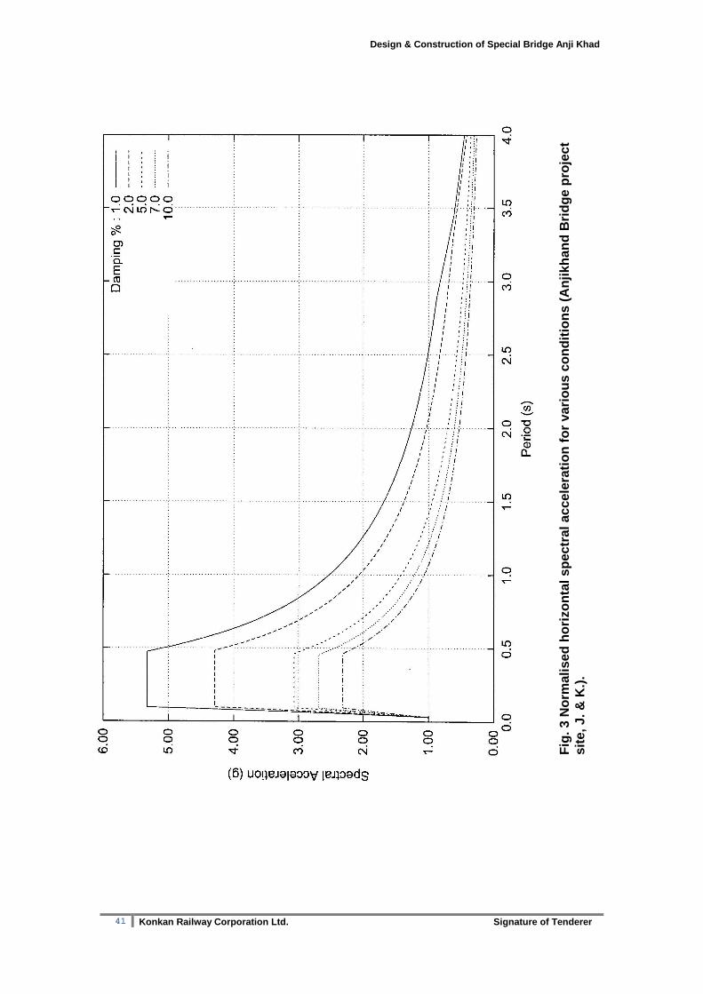
intervals of 0.01 sec. Figure 3 gives the shape of normalised acceleration spectra for
1, 2, 5, 7 and 10% damping. The equation and its parameters for the shape of
spectra and to compute digital values of the same are given in Table-II.
6.2 DESIGN SPECTRA: Having obtained spectra and time history of ground motion for maximum credible horizontal earthquake conditions, the Design Spectra are obtained using appropriate reduction factors. The practice of working out the design basis spectra (Spectral values corresponding to Design Basis Earthquake, DBE) from MCE spectra is widely prevalent and a factor of 0.5 has been proposed to scale down the spectra from MCE to DBE level. Also, for structures which have in built ductility and reserve energy (and are engineered accordingly) the seismic forces could be reduced further. For the class of structural systems, such reduction factors R (with respect to DBE) are given in the Table-III according to the type of lateral load resisting system of structure. DBE value shall be divided by R to obtain multiplying factors to be used in conjunction with normalized horizontal spectral acceleration shown in Fig. 3.
37 Konkan Railway Corporation Ltd. Signature of Tenderer
Design & Construction of Special Bridge Anji Khad
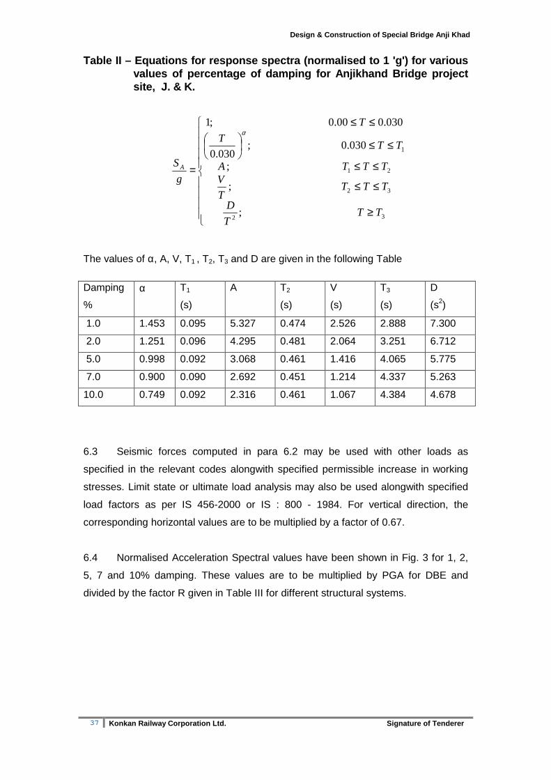
Table II – Equations for response spectra (normalis ed to 1 'g') for various values of percentage of damping for Anjikhand Bridg e project site, J. & K.
The values of α, A, V, T1 , T2, T3 and D are given in the following Table
Damping
%
α
T1
(s)
A T2
(s)
V
(s)
T3
(s)
D
(s2)
1.0 1.453 0.095 5.327 0.474 2.526 2.888 7.300
2.0 1.251 0.096 4.295 0.481 2.064 3.251 6.712
5.0 0.998 0.092 3.068 0.461 1.416 4.065 5.775
7.0 0.900 0.090 2.692 0.451 1.214 4.337 5.263
10.0 0.749 0.092 2.316 0.461 1.067 4.384 4.678
6.3 Seismic forces computed in para 6.2 may be used with other loads as
specified in the relevant codes alongwith specified permissible increase in working
stresses. Limit state or ultimate load analysis may also be used alongwith specified
load factors as per IS 456-2000 or IS : 800 - 1984. For vertical direction, the
corresponding horizontal values are to be multiplied by a factor of 0.67.
6.4 Normalised Acceleration Spectral values have been shown in Fig. 3 for 1, 2,
5, 7 and 10% damping. These values are to be multiplied by PGA for DBE and
divided by the factor R given in Table III for different structural systems.
≥
≤≤
≤≤
≤≤
≤≤
=
32
32
21
1
;
;
;
0.030 ;030.0
030.00.00 ;1
TTT
D
TTTT
VTTTA
TTT
T
g
S A
α

38 Konkan Railway Corporation Ltd. Signature of Tenderer
Design & Construction of Special Bridge Anji Khad
TABLE III – Response Reduction Factor for Different Structural System
S. N. Class of Structural System (Lateral Load Resisting) R
1. Ordinary RC moment-resisting frame (OMRF) 2.00
2. Special RC moment resisting frame (SMRF) with ductile detailing as per IS 13920
3.33
3. Steel frame
i. concentric braces 2.67
ii. eccentric braces 3.33
4. Steel moment resisting frame designed as per SP 6 3.33
5. Load bearing masonry wall buildings
i. unreinforced 1.00
ii. reinforced (as per IS 4326) with horizontal RC bands 1.67
iii. reinforced (as per IS 4326) with horizontal RC bands and vertical bars at corners of rooms and jambs of openings
2.00
6. Ordinary RC shear walls 2.00
7. Ductile RC shear walls as per IS 13920 2.67
Buildings with dual systems
8. Ordinary shear wall with OMRF 2.00
9. Ordinary shear wall with SMRF 2.67
10. Ductile shear wall with OMRF 3.00
11. Ductile shear wall with SMRF 3.33
7.0 RECOMMENDATIONS
7.1 The maximum ground acceleration corresponding to maximum considered
earthquake (MCE) may be taken as 0.34g. The corresponding value of design basis
ground motion (DBE) is recommended to be taken as 0.17g.
7.2 Figure 3 gives normalised acceleration spectra for damping values equal to
1, 2, 5, 7, and 10% and may be used along with appropriate multiplying factors for
use in design of structures/systems in the railway bridge.
7.3 For detailed time history analysis of such structures the time history of ground
motion (Appendix-II) may be used along with multiplying factors of 0.17 or 0.34 for
Design basis earthquake (DBE) or Maximum considered earthquake (MCE)
respectively.

39 Konkan Railway Corporation Ltd. Signature of Tenderer
Design & Construction of Special Bridge Anji Khad
7.4 For consideration of vertical ground motion/spectra the corresponding
horizontal acceleration spectral values may be further multiplied by a factor of 0.67.
7.5 The seismic forces as computed above may be combined with other forces
and further analysis/design carried out as per relevant codes for the concerned
structure.
7.6 The structures must be detailed appropriately so as to ensure that they
possess adequate ductility to justify the use of reduction factor ‘R’ and also for
improved seismic performance.

40 Konkan Railway Corporation Ltd. Signature of Tenderer
Design & Construction of Special Bridge Anji Khad
Fig
. 2 T
ime
hist
ory
of g
roun
d m
otio
n fo
r A
njik
hand
B
ridge
pro
ject
site
, J. &
K.
41 Konkan Railway Corporation Ltd. Signature of Tenderer
Design & Construction of Special Bridge Anji Khad
Fig
. 3 N
orm
alis
ed h
oriz
onta
l spe
ctra
l acc
eler
atio
n fo
r va
rious
con
ditio
ns (
Anj
ikha
nd B
ridge
pro
ject
si
te, J
. & K
.).
42 Konkan Railway Corporation Ltd. Signature of Tenderer
Design & Construction of Special Bridge Anji Khad
REFERENCES
1. Abrahamson, N. A. and J. J. Litehiser (1989), Attenuation of vertical peak accelerations, Bull. Seis. Soc. Am., 79, 549-580.
2. Campbell, K. W. (1981), Near source attenuation of peak horizontal acceleration, Bull. Seis. Soc. Am., 71, 2039-2070.
3. Chamberlain, C. P. and Zeitler, P.K. (1996) Assembly of crystalline terranes of the northwestern Himalaya and Karakoram, northwestern Pakistan. The Tectonic Evolution of Asia (Ed. An Yin and T. Mark Harrison), Cabridge University Press, 138-148.
4. Gansser, A. (1977) The great suture zone between Himalaya and Tibet, a preliminary account. Sci. Terre Himalaya, CNRS, 268, 181-192
5. GSI (2000), Seismotectonic Atlas of India and its environs, Geological Survey of India.
6. IS – 1893 (Part 1) (2002), Criteria for earthquake resistant design of structures – Part 1: General provision and buildings, Bureau of Indian Standards.
7. IS – 456 (2000), Plain and reinforced concrete – Code of Practice, Bureau of Indian Standards.
8. IS – 800 (1984), Code of practice for general construction in steel, Bureau of Indian Standards.
9. IS - 4326 (1993) Code of practice for earthquake resistant design and construction of buildings
10. Joyner, W.B. and D.M., Boore (1981), Peak horizontal acceleration and velocity from strong motion records including record from the 1979 Imperial valley, California earthquake, Bull. Seism. Soc. Am., 71, 2011-2038.
11. Kanamori, H. (1983) Magnitude scale and quantification of earthquakes, Techtonophysics, 93, 185-199.
12. Karunakaran, C. and Ranga Rao, A. (1979) Status of exploration for hydrocarbons in the Himalayan region – Contributions to stratigraphy and structure. Himalayan Geology Seminar, Section III, 1-66.
13. Krishna Rao, V.V. and Rao, R. P. (1979) Geology of the Tertiary belt of Northwest Himalaya Jammu and Kashmir state, India. Himalayan Geology Seminar, Section III, 149-174.
14. Sharma, K.K. (1991) Tectononomagmatic and sedimentation history of Ladakh collision zone: a synthesis. Phys. Chem. Earth, 17, 115-132.
15. Searle, M.P. (1996) Geological evidence against large scale pre-Holocene offsets along the Karakoram fault: Implications for the limited extrusion of the Tibetan plateau. Tectonics, 15, 171-186.
16. Srikantia, S.V. (1988) Himalayan thrusts and structural belts. Jour. Geol. Soc. India, 31, 210-229.
17. Srikantia, S.V. and Sharma, R.P. (1976) Geology of the Shali belt and the adjoining areas. In: The stratigraphy and structure of parts of the Simla Himalaya. Mem. Geol. Surv. India, 106(1), 69-77.
18. Srikantia, S.V. and Bhargava, O.N. (1998) Geology of Himachal Pradesh. Geol. Soc. India, pp. 406.
19. Wadia, D.N. (1966) Geology of India. Macmillan and Company Limited. 20. Wells D. L. and K.J., Coppersmith (1994), New empirical relationships
among magnitude rupture length rupture width rupture area and surface displacement Bull. Seis. Soc. Am. Vol. 84 No. 4 974-1002.