tender number: sg/cap/058/2007 - web viewnovember 2017. the information contained within this...
TRANSCRIPT

ANNEXURE B: FUNCTIONAL AND TECHNICAL SPECIFICATIONS FOR INTEGRATED SECURITY SYSTEMS
NOVEMBER 2017
The information contained within this document is confidential to ATNS in all respects and it is hereby acknowledged that the information as provided shall only be used for the preparation of a response to this document. The information furnished will not be used for any other purpose than stated and that the information will not directly or indirectly, by agent, employee or representative, be disclosed either in whole or in part, to any other third party without the express written consent by the Company or it’s representative.

TABLE OF CONTENTS1 FUNCTIONAL SPECIFICATIONS FOR INTEGRATED SECURITY SYSTEMS.....................10
1.1 SECURITY MANAGEMENT SYSTEM (SMS).....................................................................111.1.1 General Description and System Overview.......................................................................11
1.1.2 Security Sub-System Integration.......................................................................................11
1.1.3 Security Management functions........................................................................................12
1.1.4 Security Large Area Network............................................................................................12
1.1.5 Integration Description......................................................................................................13
1.1.6 System Configuration........................................................................................................18
1.1.7 System Performance..........................................................................................................19
1.1.8 Minimum Hardware Requirements....................................................................................20
1.1.9 Minimum Software Requirements.....................................................................................20
1.1.10 Operator Visual Display Units...........................................................................................21
1.1.11 Software.............................................................................................................................22
1.1.12 Archiving Historical Data..................................................................................................24
1.1.13 System Status.....................................................................................................................27
1.1.14 Current Alarm Window.....................................................................................................28
1.1.15 Graphical Display..............................................................................................................29
1.1.16 Security Management Functions........................................................................................30
1.1.17 Visitor Management Module.............................................................................................40
1.1.18 Maintenance and Spare equipment....................................................................................43
1.1.19 Graphical User Interface....................................................................................................43
1.1.20 OPERATIONS AND INCIDENT MANAGEMENT SYSTEM......................................45
1.2 ACCESS CONTROL SYSTEM...............................................................................................541.3 INTRUDER ALARM DETECTION SYSTEM.......................................................................811.4 CCTV SYSTEM.......................................................................................................................841.5 NETWORK BACKBONE SYSTEM.....................................................................................1271.6 PERIMETER INTRUSION DETECTION SYSTEM............................................................1311.7 RAISED ACCESS FLOOR SYSTEM...................................................................................1411.8 FIRE DETECTION SYSTEM................................................................................................1471.9 FIRE SUPPRESSION SYSTEM............................................................................................1531.10 INTERCOM SYSTEM...........................................................................................................1581.11 SECURITY FENCE PERIMETER LIGHTING....................................................................1601.12 EARTHING SYSTEM............................................................................................................1601.13 TRANSIENT VOLTAGE SURGE SUPPRESSION.............................................................1631.14 REMOTE / OFFSITE MONITORING...................................................................................164
Page 2 of 222

2 TECHNICAL SPECIFICATIONS FOR INTEGRATED SECURITY SYSTEMS......................1652.1 ACCESS CONTROL SYSTEM.............................................................................................1662.2 ALARM SYSTEM..................................................................................................................1752.3 CCTV SYSTEM.....................................................................................................................1802.4 SYSTEMS CONTROL...........................................................................................................1902.5 NETWORK BACKBONE SYSTEM.....................................................................................1932.6 EMERGENCY VOICE ALARM COMMUNICATION SYSTEM (EVAC)........................2062.7 FIRE DETECTION SYSTEM................................................................................................2102.8 FIRE SUPPRESSION SYSTEM............................................................................................2152.9 INTERCOM SYSTEM...........................................................................................................2162.10 PERIMETER INTRUSION DETECTION SYSTEM............................................................2192.11 SURGE PROTECTION DEVICES (SPDs)...........................................................................2212.12 CABLING)..............................................................................................................................2222.13 POWER SUPLIES (Industrial DIN Rail Mounted Power Supplies)......................................2232.14 HIGH SECURITY FENCE SYSTEM....................................................................................2242.15 PERIMETER LIGHTING SYSTEM......................................................................................2282.16 RETAINING WALL...............................................................................................................2282.17 Accessories..............................................................................................................................2282.18 Markers and Nameplates.........................................................................................................228
Page 3 of 222

1 FUNCTIONAL SPECIFICATIONS FOR INTEGRATED SECURITY
SYSTEMS
Page 4 of 222

1.1 SECURITY MANAGEMENT SYSTEM (SMS)
1.1.1 General Description and System Overview
The Contractor shall supply, install and commission a fully integrated multi-workstation security management system to facilitate the control and monitoring of all security sub-system components by means of a mouse activated operator workstation.
Operator Workstations shall be located within each local control room within the site as well as the Central control rooms offsite.
The Contractor shall provide all materials, labour and supervision required to install, commission and document the complete system as required by this specification, and as indicated on the accompanying drawings.
The SMS offered shall have demonstrated proven operation in a minimum of five (5) facilities, and a list of reference sites shall be provided as part of the tender response.
1.1.2 Security Sub-System Integration
The Security Management System (SMS) shall provide the integration platform for all Security Sub-Systems. It is a specific requirement of this tender that the SMS shall interface directly with all sub-system hardware by means of existing drivers supplied as part of the SMS software. Hardwired interface of one sub-system to another to achieve integration with the SMS shall not be accepted.The SMS software shall perform all interlocking functions between the various subsystems i.e. the automated switching of CCTV images upon intercom selection, door alarms, fire alarms, intrusion detection etc. The SMS software shall be capable of configuring the necessary interlock functions either by providing a configuration table or an internal scripting site or a combination of the two. The programming of interlock functions within sub-system hardware/software as a means of achieving the required functionality shall not be accepted. The tenderer shall provide a description of the interface protocol for each sub-system hardware platform offered as part of this tender, in the clause by clause compliance statement to be returned with their submission. The SMS software shall provide the necessary soft control functions to eliminate the need for any additional control components such as keyboards, joysticks or proprietary operator panels.
System operators shall be capable of controlling all functions of the sub-system hardware components via a single mouse driven operator workstation running on a Windows 7 or later operating platform within a single Security Management Application. The following sub-system hardware components shall be directly integrated with the Security Management System by means of a high-level interface:
a) Access Control based door locking systemb) IP Intercom systemc) IP based CCTV systemd) Perimeter Intrusion Detection systeme) Spikes & Boom Barrier systemf) Motorized gates systemg) Intruder alarm system
Page 5 of 222

h) Fire detection systemi) Fire suppression systemj) Uninterruptible Power Suppliesk) Backup Generator
The following devices shall be interfaced to the Security Management System via the PLC based door locking system by providing remote multi-I/O modules where required:
a) Non-controlled door position switches (DPS)b) Over voltage suppression devicesc) Standby Generator Sets
1.1.3 Security Management functions
The Security Management System (SMS) shall provide the following software functions:Graphical representation of the sites by means of multiple area mapsControl and Monitoring of PLC controlled DoorsControl and Monitoring of Access Controlled DoorsControl and Monitoring of Intercom StationsManual and event based selection of IP based fixed and PTZ CCTV camerasControl of Pan, Tilt, Zoom functions of CCTV CamerasEvent based Black Screen Management of CCTV CamerasConfiguration of Network Video Recording Event based retrieval of recorded video footageControl and Monitoring of Perimeter Detection devicesControl and Monitoring of motorized gatesMonitoring of centralized UPSsMonitoring of Duress ButtonsMonitoring of Standby Generator setsStaff and Visitor EnrollmentSpikes & boom barriers
1.1.4 Security Large Area Network
A high speed 1GB high speed Ethernet network shall be supplied, installed and commissioned by the contractor, which shall provide system networking for all security sub-system hardware.It is a specific requirement that all sub-system hardware shall interface either directly or by means of IP converters within the local equipment room in each building. All communications between buildings shall be IP based.The LAN shall be installed in a star topology with the star point being situated at the most centrally located Security Equipment room in the site. Each local equipment room shall be equipped with a sufficient number of 24 port 10/100 Layer 3 Managed PoE Ethernet switches with a minimum of two 1GB uplink ports. Sufficient Switches shall be provided to enable the termination of all 10/100 devices provided.The 1 GB Uplink ports shall be networked via fiber optic converters to the Central equipment room and terminated into a 24 port 10/100/1000 Layer 2 Switch.The contractor shall supply and install all cables, enclosures, switches and any other components to make the system complete.
Page 6 of 222

1.1.5 Integration Description
1.1.5.1 PLC Based Door Locking Sub-System
The locking sub-system hardware shall be integrated with the SMS via a high-level Interface (HLI). The full functionality of the locking sub-system hardware shall be integrated with the SMS to provide enhanced features including but not limited to:
Door LockDoor UnlockDoor InhibitDoor Status monitoringDoor Alarm annunciationDoor auto-closeHardware fault diagnostics.
The locking sub-system shall control and monitor all electrically controlled swing doors, sliding doors and gates within the site.
The locking system control hardware (I/O points) shall be an integrated function of the door control module as described in this specification.
1.1.5.2 I/O Alarm Monitoring Sub-System
An Alarm monitoring sub-system shall be provided to monitor specific hardwired alarm I/O points within the site, which shall be managed by the PLC based door locking system hardware. Such Alarms shall include but not be limited to the following:
DPS monitored door alarms.Standby generator alarms.Surge Voltage alarms.
The alarm monitoring system control hardware (I/O points) shall be an integrated function of the door control module as well as the multiple I/O control modules described in this specification.
1.1.5.3 Access Control Sub-System
The Access Control requirement shall consist of two sub-components:a) Biometric Logon of Operator Workstations
Each Security Management System Operator Workstation shall be provided with a vandal resistant fingerprint reader for logging on to the Workstation. Operator’s commands and events shall be logged into the centralised database against the relevant Operators details.
b) Biometric Access Controlled DoorsEach Access Controlled door shall be equipped with a Fingerprint Reader as detailed in the specification. The following functionality shall be provided by the Access Control System:
a) Staff Time and Attendance Managementb) Visitor Management
Page 7 of 222

1.1.5.4 Intercom Sub-System
The IP Intercom sub-system hardware shall be integrated with the SMS via a high-level Interface (HLI). The full functionality of the system shall be integrated with the SMS to provide enhanced features including but not limited to:
Station Call-InStation Fault AnalysisCall In DivertCall AnswerCall CancelCall-In QueuingTamper Alarm monitoringThreshold Monitoring (Disturbance detection)Individual station Speaker and Microphone sensitivity adjustment
The Intercom system shall enable the selection of any individual or group of intercom stations by any operator workstation within the site.
1.1.5.5 IP Based CCTV Sub-System
A fully IP based CCTV System shall be integrated with the SMS via a high-level Interface (HLI) at each workstation or server. The full functionality of the system shall be integrated with the SMS to provide enhanced features including but not limited to:
Camera to Monitor commandsSequence to Monitor commandsSequence programming commandsPan, Tilt, Zoom commandsPTZ preset select commandsPTZ preset save commandsMonitor Blanking commandsBlack screen technology
Camera Types that are not available as direct IP cameras shall be converted to IP via a single channel H264 IP Video Encoder mounted directly at the camera position.
1.1.5.5.1 IP Based Network Video Recording Sub-System
A fully IP based Video Recording System shall be integrated with the SMS whereby all images are stored on Digital Video Recording Servers installed within the various security equipment rooms in the site. NVR’s shall be connected directly to the appropriate 24 Port managed switches within the local equipment cabinets.
The managed Ethernet switches shall be configured to limit the Video traffic onto the incoming 1Gb uplink ports on the switches, by restricting outgoing streams to those required for live video feeds based on Operator selection, and recorded video footage being reviewed by Central Operator Workstations or the Operations room.
Page 8 of 222

In order to minimize traffic on the 1 GB uplink ports, the allocated recording stream on each of the Direct IP cameras or IP Video Servers shall be assigned to the IP address of the Network Video Recorders within the local subnet.
The full functionality of the NVR system shall be integrated with the SMS to provide enhanced features including but not limited to:
a) Individual Channel Record and Stop commands based on other sub-system conditions such as Intercom, CCTV and Locking.
b) Channel Playback selectc) Playd) Stope) Pausef) Backg) Left Jumph) Right Jumpi) Left Shiftj) Right Shiftk) Plusl) Minusm) Logn) Search
The search and playback site shall be an integrated function of the SMS, and shall not require any third-party software platform to perform these functions.
Upon operator request the SMS system shall be capable of instructing the NVR system to playback video images to allow proper investigation of the visual event. The SMS management workstation shall be capable of recalling associated historical Video and Audio data based upon events logged to the event recording database on the severs.System supervisors with the correct user level shall be able to query the event database as described in this specification and by double-clicking on a specific event shall be presented with the associated Video and Audio footage automatically.
1.1.5.6 Perimeter Intrusion Detection Sub-System
The Perimeter Intrusion Detection system shall be fully integrated with the Security Management System by means of a TCP/IP socket interface (High Level Interface), in order to carry out logical connections with other security sub-systems such as the CCTV and Digital Video recording systems.
The operator shall be able to select a graphical layout of the entire site, which shall also be automatically activated upon an alarm event from the perimeter fence system.
The Security management system shall be capable of, but not limited to the following monitoring and control functions relating to Perimeter Detection:
a) Non-Lethal shock energizer loop open circuit statusb) Non-Lethal shock energizer loop short circuit status
Page 9 of 222

c) Non-Lethal shock energizer loop normal statusd) Digital expansion Input statuse) Field Node communication statusf) Field cabinet tamper statusg) Field Node logic monitoring status (Light on status)h) Field Node battery charger voltagei) Sensor alarm Acknowledge j) Loop alarm Acknowledgek) Sensor alarm Resetl) Loop alarm Resetm) Inhibit Digital Expansion Input alarmn) Inhibit Field kiosk Tamper alarmo) Individual Sensor sensitivity settingp) Loop sensitivity setting
1.1.5.7 Fire Detection System
The Main Fire Detection Panel shall be fully integrated with the SMS via a high-level Interface (HLI) at the redundant SMS server workstations. The full functionality of the system shall be integrated with the SMS to provide enhanced features including but not limited to:
a) Detector Healthy statusb) Detector Alarm statusc) Detector Fault/Maintenance statusd) Detector Inhibit statuse) Detector Inhibit Commandf) Detector Un-inhibit Commandg) Alarm Silence Commandh) Alarm Reset Commandi) Synchronize Clock Commandj) Communication Failure Alarm
The position and status of each Detector, Sounder and Manual Call Point unit within the site shall be indicated on the appropriate area map of the SMS.
A Fire Detection layer On/Off option shall be available through the menu structure, which shall toggle the display of the smoke detector icons on and off as required. This function is required to minimize congestion of icons on the area maps, due to the location of other sub-system equipment icons.
Upon an alarm condition regardless of Fire Layer status, the affected detector icon shall be displayed, and the alarm condition shall be presented to the operator within the Fault queue as described in the specification.
1.1.5.8 Centralized UPS System
The Dual redundant centralized UPS's shall be fully integrated with the Security Management System by means of a High-Level Interface (HLI), to provide operators and technicians with detailed status and alarm conditions regarding the UPS systems.
Page 10 of 222

Due to the Centralized configuration, the following detailed diagnostic information is required, and shall be presented to the operator via a drop-down menu option within the SMS:
UPS Data:i. Manufacturer
ii. Typeiii. Serial Numberiv. Software Version
Battery Data:i. Battery Status
ii. Time Remaining in minutesiii. Remaining Charge in %iv. Battery Voltagev. Battery Current
vi. Battery Temperature in Deg C
AC Input Data:Frequency per phaseVoltage per phaseCurrent per phasePower per phase
AC Output Data:i. Frequency per phase
ii. Voltage per phaseiii. Current per phaseiv. Power per phasev. Load % per phase
UPS Alarm Conditions:i. Battery Failure
ii. On Battery Poweriii. Low Batteryiv. Depleted Batteryv. Over Temperature
vi. Input Supply Out of Limitsvii. Output Out of Limits
viii. Output Overloadix. Bypass Activex. Bypass Inhibited
xi. Charger Failurexii. Fan Failure
xiii. Fuse Failurexiv. Diagnostic Test Failurexv. Communications Failure
xvi. Shutdown Pendingxvii. Shutdown Imminent
Page 11 of 222

All alarm conditions shall be presented to the operator within the Fault queue as described in the specification.
1.1.6 System Configuration
The Interactive Security Management System (SMS) shall consist of multiple Operator Workstations, situated in the local, movement and central control rooms, and shall be networked by means of a Fibre Optic Large Area Network (LAN). This network shall be a dedicated security network for use by the SMS only.The network interface between control rooms shall be by means of a Fibre Optic medium, and shall form a star configuration from the Central Control room to each local control room to ensure local system autonomy.
All operator functions shall be controlled by means of a mouse, and shall require the minimum movement and actions in order to complete a required task.The audio sub-system components within each control room shall form an integral part of the control console, and shall not require the use of external control equipment such as PTT buttons, Operator Keyboards etc.All security sub-system control functions shall be interlocked to ensure that functional procedures are adhered to.The following Interlock functions shall be programmed as an integrated function of the Security Management System:
The selection of Cameras prior to Door openingThe selection of Intercom communications prior to Door openingAutomatic Camera select upon door openingMonitored door interlockingAutomatic Camera selection upon Intercom activationAutomatic Video recording on camera image activityAutomatic event recording on individual operator activityAutomatic Control console “LOG-OFF” on control room door Interlock capability according to operator log-in level
Alarm processing, alarm logging, alarm response data entry, graphical and text based user interface, data entry, and other system management functions shall be performed by the SMS operator workstations connected to the SMS network. The operator workstations shall be located in the Central Control Room and other nominated locations.All Distributed control modules as other than door control modules mounted in door headers are to be suitably mounted within secure enclosures to the approval of the Engineer and located in the respective buildings' security and communications equipment cupboard, or other secure area as approved by the Engineer.The SMS shall utilize a single global database and shall be fully distributed to Distributed control modules connected to the SMS security network. All system operators shall have limited access to this information/data from the operator workstations. The level of access shall be controlled by use of the Biometric logon site available at each operator workstation.The system shall be designed such that failure of any control module or operator workstation shall not functionally affect the operation of any other module, network, building or Operator workstation connected to the SMS network.
Page 12 of 222

Similarly, should any area lose power or suffer a loss in communications due to a break in the communications cabling, all Distributed control modules installed in that area shall continue to operate with no loss of functionality.
The SMS shall be fully programmable to allow:
a) Response instructions to be displayed for all alarms types.b) Use dynamic (real time) graphics to display device status.c) Initiate operator commands via system tailored icons.d) Display building layouts in a graphical representation.e) Easy to follow menus with single key select options, to assist in the daily routine
operations of each site.f) Allocate alarm priorities.g) Set Alarm response properties.h) Set lock/unlock and access/secure operating schedules.i) Generate User defined reports.
The contractor shall allow adequate time to liaise with the Engineer in order to detail any user specific requirements necessary for the operation of each building, system, alarm type, and alarm response configuration within the system. This shall include the configuration of maps, report formats, access schedules, alarm response instructions and the like, to suit each operator workstation.
The system shall be modular in design to allow for future system expansion with minimum cost and disruption to the existing operational system.
Tenderers are to specify the systems total capacity for future expansions.Such upgrades shall not render a redundancy in field hardware, the Central Processing Units or any major component of software, firmware or operating systems.
1.1.7 System Performance
1.1.7.1 Central Operator Workstations
The interaction delay between activating a control icon on any given operator workstation and the controlled point activation, (i.e., the lock), shall be no greater than one second (1 sec).The interaction delay between controlled point activation and any given operator workstation response either by activation of an audible alarm and/or the associate icon changing state (color) shall be no greater than one second (1 sec).The interaction delay between recalling any floor plan at any given operator workstation shall be no greater than one quarter of one second (0.25) second.
1.1.7.2 Local Operator Workstations
The interaction delay between activating a control icon on any given operator workstation and the controlled point activation, (i.e., the lock), shall be no greater than one half of one second (0.5 sec).
Page 13 of 222

The interaction delay between controlled point activation and any given operator workstation response either by activation of an audible alarm and/or the associate icon changing state (color) shall be no greater than one half of one second (0.5 sec).The interaction delay between recalling any floor plan at any given operator workstation shall be no greater than one quarter of one second (0.25) second.
1.1.8 Minimum Hardware Requirements
1.1.8.1 Operator Workstations
Logon Reader:Vandal resistant Finger Print verification reader for automatic operator identification and logon.
1.1.8.2 Management Workstation
A single Management Workstation shall be provided.Logon Reader:Vandal resistant Finger Print verification reader for automatic operator identification and logon.
1.1.8.3 Server Workstation
A redundant server configuration shall be provided.
1.1.9 Minimum Software Requirements
The Security Management System (SMS) software shall be design specifically for Integrated Security Management Applications, shall have a proven track record in the security industry, and shall be an Off-the-shelf package available through a distributor network. The off-the–shelf software shall be programmed and tailored to the specified functions and features described herein and as indicated on the accompanying drawings.The software shall convey and accurate floor plan of all areas that require display on the VDU. The software shall utilize the maximum resolution and colours of the SVGA monitor to enhance and simplify the displayed control and status information. Fast orientation and ergonomics will be the goal of the graphic displays.The software shall provide integrated Biometric (Fingerprint) log-on security functionality with security level protection for all Mouse driven operator workstations. The Biometric (Finger print) logon site shall be capable of providing a one too many search algorithm to confirm operator credentials, without the need for entering user details or the swiping of a personal identification card.There shall be a minimum of ninety-nine (99) levels of access, and shall be expandable.The software shall provide a user database within the Management workstation. The database shall support a minimum of two thousand (2000) users.The software shall provide on-line utilities accessed through the Management workstation menu structure. These utilities shall provide the system supervisor with the ability to edit and update required data bases, system operating variable, report configuration and generation, alarm tags and point descriptions, etc. These utilities shall be protected by security levels and Biometric Access.All software licenses shall be transferred to the Owner at completion of the project. This shall include but not be limited to all original installation disks, software manuals, equipment manuals, etc. All project specific applications software shall be transferred at the end of warranty period.
Page 14 of 222

1.1.10 Operator Visual Display Units
1.1.10.1 General
The SMS system offered shall be capable of providing a multiple operator workstation environment, which may be configured for full or selective operational & functional monitoring and control of select areas and functions.Operator workstations shall be located as indicated in the tender drawings issued.The operator workstations shall operate in both text and graphics based display. Any operator workstation enabled via the Biometric logon system shall be capable of controlling any area within the site providing the respective operator is authorized to do so.The operator workstation shall also be capable of implementing changes to the system configuration and parameters, provided the operator has the necessary administration rights.Entries, deletions or modifications to the configuration shall be possible via the operator workstation VDU/Keyboard without loss of, or degradation to, any other system functionality.The following workstation functions shall be possible:
a) Displaying point status information.b) Manually initiating control commands.c) Displaying system events and alarms.d) Displaying staff, visitor photographs for positive identification.e) Enrolling and verifying staff, visitor fingerprints. (Visitor Management module)f) Assigning operator access levels.g) Altering time schedules and creating new time schedules.h) Assigning or modifying time schedules for automatic operation of monitored
doors/gates and redirection of duress alarms and indicators appropriate to the user's building/department/etc.
i) Overriding time controlled functions, momentarily, to allow operator control of doors/gates/and the like.
j) Altering existing or assigning new descriptions or actions.k) Displaying status of all alarm sectors within the user's areas.l) Remotely operate doors/gates within their restricted areas.m) Displaying all appropriate building activities.n) Performing on-line backup copies of complete system without any degradation
in the overall system performance.o) Displaying building alarms including duress push buttons, etc.p) Enable the viewing of Sub-system status icons to be enabled or disabled through
a built-in menu structure.
All of the above shall be restricted by user level based on the finger print access to the operator workstation.
1.1.10.2 Monitors
All operator workstations shall be of robust construction, ergonomically designed to minimize operator fatigue.
1.1.10.3 Keyboards
Page 15 of 222

Keyboards shall be supplied with all workstations, however shall only be used for commissioning and maintenance purposes. All operator functions shall be performed by means of an optical mouse, with system screens being designed so as to require the minimum operator action. Functions such as audio system Push to talk, volume up and down control etc shall be possible by means of function keys on the SMS workstation.
1.1.10.4 Printer
A high-quality Inkjet printer shall be supplied, installed and commissioned as part of this contract, for use with the management workstation in order to generate user defined management reports.
The printer shall incorporate a visible control panel with LED indication for power on, paper out and ready.The printer shall be installed and configured into the Management workstation to be installed within the Central Control Room.The printer shall be supplied with both power and data cables of suitable length to suit the location. In addition, the printer shall be set up complete with one full box of paper and two spare ink cartridges each.
1.1.10.5 Mouse
All mouse devices shall be optical of robust construction and suitably secured by an interconnecting cable.
1.1.10.6 Networking
Each SMS workstation installed on the security LAN shall be capable of monitoring and reporting the current status of all workstations on the network.Should communications between workstations or control equipment be disrupted, an alarm shall be generated at the Central Control Room Operator workstations to alert the operators of the failure within the communications network.Alarms generated shall be displayed at the operator stations, while updating the system database with the Time, Date and relevant workstation detail.Failure of any operator workstation shall not prevent communication between any other workstation or Distributed control modules and their associated devices.
1.1.11 Software
1.1.11.1 General
Software shall be fully proven prior to being supplied, installed, tested and commissioned.
A list of reference sites at which the system software has been installed and operational at the date of the closing of this tender shall be provided.
The operator interface software shall incorporate English language descriptions and messages using both text based menus and graphical/icon displays. All configurations (e.g. entering of
Page 16 of 222

alarm response properties, adjusting time schedules, user data, etc) shall be performed on-line without effecting the operation of the overall system.
Selective access to different operator functions shall be configured based on an operator’s user level. User levels shall be determined from the Biometric verification each time an operator logs on to a workstation.
After any predefined period, if no operator activity has occurred at the operator workstations, that station shall automatically request Biometric verification failing which the station shall log off.
The time period before automatic logging off of workstations shall be user configurable, and shall be determined during commissioning of the system, in liaison with the Engineer.
1.1.11.2 Operating System
The operating system shall be a recognized and widely accepted standard operating system that shall suit the requirements of the system to be installed. The operating system shall be a real time multi-user/multi-tasking system such as Windows 7.
The operating system shall have proven and demonstrated reliable operation in the security environment.
Facilities shall be provided to store all programs on site and include all equipment necessary to backup and reload all system programs, including the operating system with all user specific system parameters.
1.1.11.3 System Access
Operators shall be required to "log on" to operator workstations using the finger print reader provided at each operator station before being able to access the system or user information, reset alarms or access any other system functions.
Access to all workstations shall be limited through allocation of access levels.A minimum of 2000 users and 99 User levels shall be available. Only users allocated with a user level of 99 shall be capable of the assignment and changing of passwords to all levels.
Each operator shall be allowed to access different operator commands and functions, and view certain individually assigned events, menus and functions based on their assigned user level.
1.1.11.4 Scheduling
The SMS system shall have the ability to configure schedules which do not restrict the user to pre-determined times, dates or access levels. Access to and editing of these schedules shall be possible via the Management workstation.
The following schedules shall be configurable:
a) Operator station Access times.b) Designated Alarm priority changes.
Page 17 of 222

c) Automated door locking/unlocking.
1.1.12 Archiving Historical Data
1.1.12.1 General
Archiving of historical data shall take place automatically according to a configurable time frame, which shall be set via the Management workstation. The archived files shall be stored on the Raid 1 servers situated in the Central Control Room equipment rack. The system shall be capable of storing archived history files for a minimum period of 12 months.
Archived history files shall be read directly from the current or archived databases, without terminating or suspending the logging of current events.
1.1.12.2 Overwriting
The SMS software shall display an alarm to system operators warning of the imminent loss of archived data once the available disk space becomes full. The alarm shall occur with sufficient margin to allow the systems operator to execute a manual history file dump to the removable storage medium, if required (normally 80%). The percentage alarm set point shall be variable by the highest user level.
1.1.12.3 System Logging
The server workstations shall be capable of logging the following data:Event related data:
Item Database Fields1 Time and Date Stamp2 Equipment Type3 Control Area4 Equipment Designation5 Equipment Location6 Alarm/Event Type7 Alarm/Event Status8 Responsible Operator9 Operator Workstation Name10 Control Area11 Alarm/Event Priority
Logged Events/Alarms:
Item Intercom Events/Alarms1.1 Intercom Station Call in 1.2 Intercom Station Activated1.3 Intercom Station I/O Failure1.4 Intercom Station Tamper Alarm1.5 Intercom Station Threshold Alarm
Page 18 of 222

1.6 Intercom Station Fault1.7 Intercom Call-in Transferred1.8 Intercom Call-in Unanswered1.9 Intercom Station Isolated1.10 Intercom Station Isolated warning1.11 Intercom System Hardware Failure1.12 Intercom System Communication Failure1.13 Intercom Alarm/Failure Acknowledged1.14 Intercom System Call Central Command1.15 Intercom System Call Movement CommandItem CCTV Events/Alarms2.1 CCTV Camera Activated2.2 CCTV PTZ Preset Edited2.3 CCTV Sequence Selected2.4 CCTV Sequence Edited2.5 CCTV System Hardware Failure2.6 CCTV System Communication Failure2.7 CCTV Alarm/Failure Acknowledged
Item NVR Events/Alarms3.1 NVR Channel Record Command3.2 NVR Channel Halt Record Command3.3 NVR System Hardware Failure3.4 NVR System Communication Failure3.5 NVR Alarm/Failure Acknowledged
Item Door Events/Alarms4.1 Door Open Command4.2 Door Closed Command4.3 Door Fault on Closing4.4 Door Fault on Opening4.5 Door Forced Open Manually4.6 Door Open outside of limits4.7 Door Open for extended period4.8 Door Control module Communication Failure4.9 Door DPS Opened4.10 Door DPS Closed4.11 Door Interlock Override Command4.12 Door Group Activated4.13 Door Group Edited4.14 Door Emergency Release Activated4.15 Door Control System Hardware Failure4.16 Door Control System Communication Failure4.17 Door Alarm/Failure Acknowledged
Page 19 of 222

Item Gate Events/Alarms5.1 Gate Open Command5.2 Gate Stop Command5.3 Gate Close Command5.4 Gate Fault on Closing5.5 Gate Fault on Opening5.6 Gate Forced Open Manually5.7 Gate Open outside of limits5.8 Gate Open for extended period5.9 Gate Control module Communication Failure5.10 Gate Alarm/Failure Acknowledged
Item Boom & Spike Barrier Events/Alarms6.1 Boom & Spike Barrier Open Command6.2 Boom & Spike Barrier Stop Command6.3 Boom & Spike Barrier Close Command6.4 Boom & Spike Barrier Fault on Closing6.5 Boom & Spike Barrier Fault on Opening6.6 Boom & Spike Barrier Forced Open Manually6.7 Boom & Spike Barrier Open outside of limits6.8 Boom & Spike Barrier Open for extended period6.9 Boom & Spike Barrier Control module Communication Failure6.10 Boom & Spike Barrier Alarm/Failure Acknowledged
Item Intrusion Events/Alarms7.1 Intrusion Zone Activated7.2 Intrusion Zone Alarm Acknowledged
Item Panic Button Events/Alarms8.1 Panic Button Activated8.2 Panic Button Activation Acknowledged
Item UPS Events/Alarms9.1 UPS Mains Failure Alarm9.2 UPS Load on Bypass9.3 UPS Battery Low9.4 UPS Battery Failure9.5 UPS Load not protected9.6 UPS Surge Arrestor Failure9.7 UPS Communication Failure9.8 UPS Alarm/Failure Acknowledged
Item SMS Events/Alarms10.1 New Operator Enrollment Successful10.2 New Operator Enrollment Failed
Page 20 of 222

13.3 Operator Details Edited13.4 Operator Details Deleted13.5 Workstation Logon Successful13.6 Workstation Logon Failed13.7 Workstation Unauthorized Access Attempted13.8 Workstation Manual Logoff13.9 Workstation Automatic Logoff13.10 Workstation Inhibited13.11 Workstation Re-instated13.14 Workstation Online13.15 Workstation Offline13.16 Workstation Communication Failure13.17 Workstation Alarm/Failure Acknowledge
1.1.12.4 System Reporting
The SMS shall be capable of performing SQL queries to the current or archived databases on the server workstations, format the data into customized reports which shall allow for the following:
a) Display of all relevant information on any individual alarm point including alarm point identification by device number and alarm point status.
b) Display all alarm points in the system in alarm or normal condition, as a single log.
c) Display all emergency procedures applicable to any alarm type with corresponding alarm response actions and locations, per alarm device.
Reporting details shall include:
a) Alarm point status b) Alarm count per device.c) Alarm activity over a time period, selected by time and date.d) Display of selected alarm transactions based on alarm type and a calendar / time
period.e) Display system operators login/out historyf) Display all operator commands entered by any or all operators based on
time/calendar interval.
1.1.13 System Status
The SMS shall provide a menu option which, when selected, allows the system to display or print a list of current alarms, faults and conditions including the current fault conditions relating to SMS workstations, Distributes control modules, sub-system equipment hardware and associated devices.In graphical display mode the system shall display maps of each building complete with all internal levels and shall indicate all systems equipment status (i.e. locked/unlocked; open/closed; secure/access; isolated/active; alarm; tamper etc).
Page 21 of 222

1.1.14 Current Alarm Window
The system shall provide an efficient and reliable alarm handling procedure and shall include both audio and visual annunciation, logging to the database and recording of the history file the device description, point description, location, time and date the alarm occurred.
The system software shall have the ability to route only selected alarms to specific operator workstations, allowing different locations or applications to be segregated on a building or system basis.
All systems activity shall be presented to ensure proper actions have been taken and that no alarm is left unattended for any lengthy period. Alarms, which have been acknowledged, and not cleared/reset shall be clearly distinguishable.Upon occurrence of an alarm(s) a user configurable audible tone shall sound at the operator workstation(s) and display an indication of the incoming alarm together with its priority.
If there are additional alarms to acknowledge the operator’s station shall continue to sound the appropriate alarm tone, display the number of alarms waiting and identify the highest priority alarm.
The first alarm displayed shall be the highest priority alarm followed by the next highest priority alarm, etc.All alarms are required to be separately acknowledged by the operator, by means of the mouse provided to acknowledge and reset each alarm separately.
Each time new alarms are created the system shall restack the alarms so the operator sees them in order of priority.
The system shall also have an alarm/event status display available to the operator at all times on the operator’s station.
The display shall be a real-time dynamic display of alarms in the active state, or system component failures.
An audit trail shall be used to log the actions taken by all system operators in response to an alarm. The audit trail shall note:
When the alarm was activated.When the alarm was acknowledged.Who acknowledged the alarm.When the alarm was restored.
The system shall record every user command, acknowledgment and log every operator login.These transactions shall be routed to the history database.Any alarm point which has been suppressed/inhibited by the operator shall on expiry of the time zone, or when unsuppressed by the operator, generate an alarm if the alarm point is in the "active" state. The report to the operator terminal shall be the same as described above.Each alarm point shall have the site for a description of the alarm occurring. A
Page 22 of 222

Comprehensive outline for operator instructions, detailing all response actions shall be provided for all alarms.
1.1.15 Graphical Display
The SMS shall support a minimum of 150 colour maps for the purpose of displaying the location and real time status of any SMS input or output.
Graphical maps to be included within the initial configuration are to show in detail the following areas:
Site plan showing all buildings and locations of all alarm points and operator workstations.A plan of each accommodation unit and building.All buildings devices/status/alarms and the like.All building tamper, communications, power and the like devices/status/alarms and the like.Other maps as required to clearly display all alarm input within buildings, or an external equipment cubicle locations.
Each site map shall be provided with a site plan key, which shall be common to all maps and situated in the same position. The key shall provide a means for the operator to quickly navigate through the entire site without the need to use standard navigation buttons or the main site map.
All device location and statuses shall be detailed on each map and coloured accordingly for ease of recognition of both the device type and real time status. Text messaging identifying the device type, designation and alarm status shall be available in a “mouse over” or “windows hint” structure to minimize text on individual maps.
All text descriptors shall be approved by the Engineer prior to final acceptance. Liaise with the Engineer when programming these maps and other alarm/response descriptions.
Function key descriptions shall also be displayed as mouse over or windows hints.
Graphical map displays shall be of high resolution to enable accurate images to be represented. The configuration software shall provide a complete graphical design environment in order to design/edit building and site maps. A standard icon library shall be available to the designer in a window environment to enable efficient editing of existing maps by means of dragging and dropping equipment icons onto maps.
The system shall allow maps to be linked by means of navigation buttons to allow operators to "zoom" in or out to display either additional detail or an overall map.
Point status and locations shall be clearly displayed using colour-coded icons. All icons shall display real time status of each point with continuous updates being provided to any dynamic screen display.
Updates shall occur every 1 second or less. Icons shall be easily duplicated from a library of standard symbols at the configuration stage of developing the graphics.
1.1.16 Security Management Functions
Page 23 of 222

1.1.16.1 Configuration
The SMS shall consist of a multiple screen representation of the entire site, which shall contain all of the necessary icons to control all security sub system equipment and devices situated throughout the site. All icons shall be activated with the use of a mouse. All icons and status indicators shall be a minimum of 5mm in diameter. All symbols shall provide status by color and/or associated text.
1.1.16.2 Global Function Operations
Global function icons shall be located at the bottom of each graphic screen in the form of a footer window, which shall be common to all area maps. These icons, if active, shall control the global functions for the entire site.
1.1.16.2.1 System Control
Activating this icon shall cause the system to switch to the system control screen. The System Control screen shall provide a complete system diagnostic window for all sub-system components and communication systems within the entire site.
The diagnostic information shall include but not be limited to the following:
UPS System (Per Zone):Load on BypassLoad not protectedMains FailureBattery FaultBattery LowSurge Arrestor Failure
Control Hardware Status (Per Zone):
i. TCP/IP communication Failureii. Control Network communication Failure
iii. Device Network communication Failureiv. I/O Device Failurev. Communication Redundancy Integrity
vi. CCTV Matrix communication Alarm
Perimeter Protection System (Per Zone):
Intruder Detection AlarmVideo Motion Detection Alarm
Door position switch violation alarm per DPSControlled door security violation alarm per doorFire door security violation alarm per doorPanic Button activated alarm per Panic ButtonIntercom Call In Failure per Intercom
Page 24 of 222

Operator Log On Violation
Where applicable all alarm conditions shall allow for operator acknowledgement and automatic selection of the alarmed zone layout screen.
1.1.16.2.2 Site Plan
The site plan shall consist of an interactive miniature layout of the entire site, and shall be situated on the bottom Right hand side of each operator screen.
The site plan shall provide the operator with a quick method to access an individual area to monitor and / or control.
The site plan shall also indicate critical operational information to the operator, which shall include but not be limited to the following:
a) Fire Doors Unsecuredb) Sally port Doors Unsecuredc) Local Control Room Logon Statusd) Local Control Room Call In e) Local Control Room Communication Alarm
1.1.16.2.3 Volume Up
Activating and maintaining this icon shall result in an increase in the operator console speaker volume. The icon shall change status to RED to indicate activation of this function.
1.1.16.2.4 Volume Down
Activating and maintaining this icon shall result in a decrease in the operator console speaker volume. The icon shall change status to RED to indicate activation of this function.
1.1.16.2.5 Select
Activating this icon shall result in either the first audio call-in or the currently selected audio call-in in the Audio Call-in Queue to be answered. Upon answering the call, the call shall be removed from the Audio Call In queue on all workstations.
1.1.16.2.6 Reset
Activating this icon shall result in either the first audio call in or the currently selected audio call-in in the Audio Call-in Queue to be reset. Upon resetting the call, the call shall be removed from the Audio Call In queue on all workstations.
1.1.16.2.7 Push To Talk
Activating and maintaining this icon shall results in the PTT function being activated within the audio control hardware. Releasing the icon resets the PTT function.
Page 25 of 222

1.1.16.2.8 Call Central/Movement
Each local operator workstation’s footer window shall contain a “Call Central” and a “Call Movement” icon. When selected the SMS shall generate a high priority call-in at the Central or Movement Control operator workstations. Central and Movement control room operators shall respond to these call-ins in the same manner as with a normal intercom station call request.
Movement Control workstations shall be equipped with “Call Central” functionality only.
1.1.16.2.9 Audio Call In Queue
The SMS footer window shall contain an Audio Call-in queue site into which audio call requests are entered on a first in first out (FIFO) basis.
Upon receipt of an audio call-in from any intercom station in the site, the call-in detail listing the control area, equipment designation and the specific location of the calling intercom station shall be entered into a FIFO queue.
The call-in priority of each Intercom station within the site shall be individually configurable within the SMS, and station priority shall take preference over the FIFO queue. Intercom station call requests of higher priority e.g. Control room call-in requests shall be entered into the top of the queue.
The following methods of answering calls-ins shall be possible:
Highlighting the desired call-in in the Audio queue and clicking on the “Select” icon in the footer window.
Clicking repeatedly on the “Select” icon in the footer window, which shall automatically answer the oldest entry in the Audio queue.
Double clicking on any entry in the Audio queue.
Any of the above-mentioned methods of answering a call-in shall reset the currently selected intercom station and enable the selected station as well as simultaneously removing the entry from the Audio queue on all workstations.
When the local operator workstations are logged on, call-ins from the relevant local area shall be directed to the local workstation. In the event that the call is not answered within thirty seconds, the call shall be forwarded to the Central Control room workstations. Call-ins from local areas in which a local operator is not logged in, shall be forwarded immediately to the Central Control room operators.
1.1.16.2.10 Fault Queue
The SMS footer window shall contain a Fault queue site into which all security sub-system or control system faults are entered in order of priority.
Page 26 of 222

Upon receipt of any security sub-system or control system fault, the relevant fault detail including the control area, equipment designation and the specific location of the fault shall be entered into the Fault queue.
The Fault queue is intended to provide a quick reference to the system operator of current alarms, and is intended to replace functionality of the Current Alarm window described in the specification.
Faults may be dealt with in the following ways:
By right clicking on a specific fault in the queue, the operator shall be presented with an “Acknowledge” option. Clicking on the Acknowledge option shall enter the acknowledgement into the event recording system and remove the fault from the queue.
sBy double clicking on a specific fault in the queue, the appropriate area map shall be displayed with the faulty equipment control icon clearly visible. The equipment icon shall display the fault detail in a mouse-over or “hint” fashion. Right clicking on relevant equipment icon shall present the operator with an “Acknowledge” option. Clicking on the Acknowledge option shall enter the acknowledgement into the event recording system and remove the fault from the queue.
Local operator workstations shall display alarms and faults related to the immediate area of control only. Central operator workstations shall display all current alarms within the entire site.
1.1.16.2.11 Synchronized Clock System
All operator workstations footer windows shall contain a synchronized digital clock, which indicates the Date and Time in 24 Hour mode. The accuracy of the synchronized digital clock system shall be within +- one (1) minute within a thirty (30) day period, and shall be synchronized with the management workstation within the central control room each hour on the hour.
1.1.16.2.12 Operator Logon Details
The SMS footer window shall contain the detail of the currently logged on operator including full name and authorized user level.
1.1.16.3 Locking Operations
1.1.16.3.1 Door Position status (Monitored Only)
There shall be a status icon for each monitored door to indicate the position of the door. The status icon shall illuminate red when the door is unsecured and shall be green when the door is secure.
Each DPS icon shall provide mouse over or “hint” fashion detail of fault conditions relating to the equipment element as well as indicating the equipment designation.
Page 27 of 222

A right mouse click over any icon shall provide the operator with an option to acknowledge an alarm condition as well as to view the engineering properties of the element provided the necessary user level is active.
1.1.16.3.2 Unlock Icon (Swing Door)
There shall be a single control icon with visual status indication for each controlled swing door lock. Activating the UNLOCK command shall apply power to the lock and activate the UNLOCK control cycle. The associated status icon shall indicate red when the incorporated lock status switch indicates an unsecured state and green when the lock is secured. Each door icon shall provide mouse over or “hint” fashion detail of fault conditions relating to the door.
A right mouse click over any icon shall provide the operator with an option to acknowledge an alarm condition, to inhibit a door open command, or to view the engineering properties of the element provided the necessary user level is active. Inhibiting a door open command shall change the icon colour to blue.
1.1.16.3.3 Unlock / Lock Icon (Sliding & Fire Doors)
There shall be a single control icon with visual status indication for each controlled sliding door control mechanism. Activating the UNLOCK/LOCK icon shall either activate the UNLOCK cycle or the LOCK CYCLE of the mechanism in a toggle fashion. The associated status icon shall illuminate red when the door is unsecured and green when the lock is secured. Activation of this icon whilst the associated door is in travel shall cause the door to instantly change its direction of travel. Each door icon shall provide mouse over or “hint” fashion detail of fault conditions relating to the door.
A right mouse click over any icon shall provide the operator with an option to acknowledge an alarm condition, to inhibit a door open command, or to view the engineering properties of the element provided the necessary user level is active. Inhibiting a door open command shall change the icon colour to blue.
1.1.16.3.4 Open / Close / Stop Icons (Sliding gates)
There shall be three individual control icons with visual status indication for each controlled sliding gate. Activating the OPEN icon shall activate the OPEN cycle of the controlled device Activating the CLOSE icon shall activate the CLOSE cycle of the controlled device. Activating the STOP icon while the device is in the OPEN cycle or CLOSE cycle shall STOP the device. The associated status icon shall illuminate red when the locking device is unsecured and shall be green when the locking device is secured. Each gate icon shall provide mouse over or “hint” fashion detail of fault conditions relating to the door.
A right mouse click over any icon shall provide the operator with an option to acknowledge an alarm condition or to view the engineering properties of the element provided the necessary user level is active.
Page 28 of 222

1.1.16.3.5 Emergency release:
An Emergency release icon shall be provided for each housing unit day room area, which shall be used to initiate an automated opening sequence for Perimeter and Exercise yard doors. The opening sequence shall be configurable within the SMS in order to provide the most efficient opening sequence.
Activating this icon shall cause a pop-up window to appear on top of the graphically displayed area. Located within this window shall be text explaining to the operator that the activation of this function shall result in all controlled doors in the corresponding area to be released under an emergency procedure. Also located within this window there shall be three icons namely “Open”, “Close” and “Cancel”. Activating the icon with the text “Open” text will activate the emergency open routine. Activating the icon with the text “Close” text will activate result in the same doors to simultaneously close. Activating the icon with the text “Cancel” shall remove the pop-up window and resume normal operation.
Once an emergency release routine has been activated the doors in the controlled area shall open and indicate an emergency condition by flashing the affected door icons in RED. The activation of the emergency close routine shall return the icon status to normal.
1.1.16.3.6 Interlock Group Status
Activating a door lock icon that is part of an interlocked group of doors of which one or more doors are currently open, shall cause a pop-up window to appear on top of the graphically displayed area to indicate to the operator that an interlocked door is currently open and that the “Interlock Override” function should be activated to open the door.
Right clicking on the door icon shall provide the operator with an interlock lock group option, which when selected shall indicate each door contained in the relevant interlock group.
1.1.16.3.7 Interlock Override
Activating this icon shall enable the operator to override an interlocked door. The override function shall only remain active for 10 seconds. Activating a door control icon while override is active shall cause the associated door to unlock or open. When the override timeout limit is reached, the system shall return to normal operation.
During the active 10s period the Icon shall Flash RED to indicate activity.
1.1.16.3.8 Group Assign Icon
Activating this icon shall result in the door status icons of all doors in the corresponding Perimeter area to turn White. By toggling the door control icon whilst in the “Group Assign” mode shall toggle the door icon colour from White to Grey. A White icon shall indicate that the door is included in the controlled group, whilst a Grey icon indicates that it is not included in the group.
Upon activating the Group Assign icon for a second time the system shall return to a normal state and set the controlled door group into memory. Re-activation of the Group Assign icon shall cause the door control icons to indicate the current group assign status from memory.
Page 29 of 222

1.1.16.3.9 Group Release:
Activating this icon shall cause a pop-up window to appear on top of the graphically displayed area. Located within this window shall be three icons namely “Open”, “Close” and “Cancel”. Activating the icon with the text “Open” text will result in the doors included in the Group Assign memory to Open. Activating the icon with the text “Close” text will result in the doors included in the Group Assign memory to Close. Activating the icon with the text “Cancel” shall remove the pop-up window and resume normal operation.
1.1.16.4 Intercom Operations
1.1.16.4.1 Audio Control – Intercom Icon
The SMS shall provide a control icon with visual status indication for each intercom station within the entire site.
The icons shall be used to initiate or terminate an audio channel between the relevant control room operator’s audio console and the selected intercom station.
Each Intercom station icon shall provide mouse over or “hint” fashion detail of fault conditions relating to the station as well as indicating the equipment designation.
The alarm detail displayed by the “hint” function shall include:
Intercom station Tamper alarmIntercom station Threshold alarm Intercom station I/O alarmIntercom station Communications alarm
All alarm conditions shall be presented to the operator within the Fault queue as described in the specification.
A right mouse click over any icon shall provide the operator with an option to acknowledge an alarm condition, to inhibit an intercom station, or to view the engineering properties of the element provided the necessary user level is active. Inhibiting an intercom station shall change the icon colour to blue.
a) Intercom Station Call Up
Activating an intercom station icon shall open a talk path between the operator and the associated intercom station. The associated status icon shall illuminate yellow to indicate an active channel.Activating the intercom station icon a second time shall close the talk path and the status icon shall extinguish.
b) Intercom Station Call-In
Upon activation of an intercom station call-in button located on the intercom station faceplate, the associated status icon shall illuminate and flash between yellow and grey with an audible tone.
Page 30 of 222

Activating the associated intercom station icon shall open a talk path between the operator and the staff station. The status icon shall illuminate yellow and the audible tone shall silence. Once complete, activating of the staff station icon a second time shall close the talk path and the associated status icon shall extinguish.
c) Automatic termination of an audio channel
Should multiple audio call ins be received by the local operator, the operator shall only be required to select each audio icon once. The second icon selected shall initiate an audio channel to the appropriate intercom station and initiate an automatic de-select command to the previous channel.
d) Delayed Call-In
Upon activation of an intercom station call-in button on an intercom station which falls under the control of a local control workstation, provided the particular operator is logged in, the call shall at first be routed to the local operator. If the local operator fails to respond to a call in within 60 seconds, the call is automatically routed to central control. This event is to be logged to the event recording system.
e) Audio Queue
An Audio Call-in queue site shall be provided as an integrated function of the SMS system.
1.1.16.5 Closed Circuit Television (C.C.T.V.) Operation
1.1.16.5.1 CCTV. Fixed Camera Select
The SMS shall provide a single control icon with visual status indication for each CCTV Fixed Camera within the entire site.
Activating a camera icon shall cause the associated camera to be switched to the relevant operator’s spot monitor via the IP Interface to the CCTV Virtual Matrix. By selecting another camera icon the spot monitor image shall change accordingly.
Camera to Monitor commands shall be configured within the SMS to determine the allocation of spot monitors to operator workstations.
Currently selected camera icons shall illuminate RED, whilst un-selected icons shall illuminate GREEN.
Each Camera icon shall provide mouse over or “hint” fashion detail of the camera designation.
A right mouse click over any icon shall provide the operator with an option to view the engineering properties of the element provided the necessary user level is active.
1.1.16.5.2 C.C.T.V. PTZ Camera Select
Page 31 of 222

The SMS shall provide a single control icon with visual status indication for each CCTV PTZ Camera within the entire site.
Activating a PTZ camera icon shall cause the associated camera to be switched to the relevant operator’s spot monitor via the High Level Interface to the CCTV Matrix. By selecting any other camera icon the spot monitor image shall change accordingly.
Camera to Monitor commands shall be configured within the SMS to determine the allocation of spot monitors to operator workstations.
Currently selected PTZ camera icons shall illuminate RED, whilst un-selected icons shall illuminate PURPLE.
Each PTZ Camera icon shall provide mouse over or “hint” fashion detail of the camera designation.
A right mouse click over any icon shall provide the operator with an option to view the engineering properties of the element provided the necessary user level is active.
1.1.16.5.3 C.C.T.V. PTZ Control
Once a PTZ camera icon has been selected by the operator, the SMS shall provide a pop-up control window, which shall allow the following PTZ control functions:
a. Pan Leftb. Pan Right c. Tilt Upd. Tilt Downe. Simultaneous Pan Left, Tilt Upf. Simultaneous Pan Right, Tilt Upg. Simultaneous Pan Left, Tilt Downh. Simultaneous Pan Right, Tilt Downi. Zoom Inj. Zoom Outk. Continuous rotate Left l. Continuous rotate Rightm. Rotate Stopn. Preset Position Selecto. Guard tour initiate
1.1.16.5.4 C.C.T.V. PTZ Preset Save
The SMS shall provide the operator with a menu option which shall initiate a pop-up control window, which shall allow the following PTZ control functions:
a. PTZ Camera Select (1-n)b. PTZ Preset Select (1-99)c. Pan Leftd. Pan Right
Page 32 of 222

e. Tilt Upf. Tilt Downg. Simultaneous Pan Left, Tilt Uph. Simultaneous Pan Right, Tilt Upi. Simultaneous Pan Left, Tilt Downj. Simultaneous Pan Right, Tilt Downk. Zoom Inl. Zoom Outm. PTZ Preset Store Commandn. PTZ Preset Load Command
The SMS shall be able to assign a specific PTZ Preset position to a standard fixed camera icon. The operator shall be able to click on a fixed camera icon, which shall load a PTZ preset position onto the appropriate spot monitor.
1.1.16.5.5 Sequence to Monitor Select
The SMS shall provide a single control icon with visual status indication for each Monitor within the individual control rooms.
A control room layout map shall be configured within the SMS, indicating the physical layout of the control desk and the CCTV monitors for the relevant SMS workstation.
The Monitor icon shall illuminate RED if a CCTV sequence has not been assigned to a specific monitor, and GREEN when a logical sequence has been assigned. The sequence number and description shall be displayed within the Monitor icon when a logical sequence has been assigned.
The operator shall be able to select the desired camera sequence by means of a Right mouse key function on the monitor icon.
Camera sequences may be assigned to any Monitor in the site including the spot monitors if required, however the manual selection of a camera image shall automatically override the sequence allocation.
1.1.16.5.6 Perimeter Detection - Black Screen Technology
The SMS shall provide integrated Black screen technology, which shall enable the automatic selection of relevant Perimeter Cameras to be allocated to Video Wall Monitors in the case of a Perimeter Detection alarm.
The SMS through its high-level interface to the Perimeter Detection, CCTV and NVR sub-system hardware shall make logical selections of camera images to the dedicated video wall monitors situated in the Central Control room.
Once a Perimeter alarm is triggered, the relevant zone fixed camera image shall be switched to the dedicated monitor along with the zone cameras on each side of the alarm zone.
Page 33 of 222

The technology is required to ensure that all Perimeter alarm conditions are brought to the attention of the Central Control room operators immediately, and to present them with the necessary information to respond to the event.
The monitors to the left and right of the ALARM ZONE monitor ensure that an Intruder shall be visible should he/she move to the left or right of the immediate alarm zone. The PTZ preset position allows the operator to immediately view the alarm zone, and to follow the Intruder via the PTZ control functions.
1.1.17 Visitor Management Module
The Access Control hardware provided shall support the Visitor Management System, which shall be provided as a fully integrated module of the Security Management System provided under this contract.The Visitor Management System Module (VMS), shall provide for a fully integrated Biometric based Visitor, Staff identification System providing the following components as a minimum:
Visit BookingVisitor, Staff Enrolment Visitor, Staff VerificationVisitor, Staff location trackingVisitor ManagementStaff Management (Time & Attendance)Integration to Security Management System
1.1.17.1 System Components
The base system shall consist of the following components, however shall be indefinitely expandable to provide additional Visitor points, staff tracking points, as may be required.
a) Visitor Enrolment stations (General or Visitors entrance gate).b) Visitor Verification stations c) Management Administration station (Administration building).
1.1.17.2 Component Description
1.1.17.2.1 Visitor Enrollment Station
The Visitor Enrollment Station shall consist of a dedicated PC workstation situated at the general or visitor’s entrance. The station shall consist of a PC, fingerprint reader, Camera, adhesive label printer and a storage tray for temporary Visitor cards.The station shall be used to enroll visitor information into the system, and to print and issue a temporary Visitor identification card to each visitor, which shall contain the visitor details with a bar code for database indexing.
1.1.17.2.2 Visitor Verification Station
Visitor Verification stations shall be installed in each Visitor area e.g. Contact and Non-Contact Visitor, and shall consist of a PC workstation and a fingerprint reader.
Page 34 of 222

The station shall be used to verify a visitor’s identity both upon entering and leaving the Visitor area.
1.1.17.2.3 Management Administration Station
The Management station shall be installed within the Administration building, and shall consist of a PC workstation, fingerprint reader, Camera, LaserJet reporting printer and a
Desktop Colour PVC identification card Printer.
The station shall be used to enroll staff members onto the system.
Staff members shall have their picture and fingerprints captured and shall be issued with a permanent staff access card, which shall be required to enter and leave the site.
1.1.17.3 System Description
In summary the objective of the system is to provide the following managerial functions within the site:
The management and tracking of staff.The management and verification of Visitors and the recording of visits.
1.1.17.4 Typical Station Allocation
StationNº
Station Type BuildingAllocation
Primary Function
1 File Server Administration Central file server (RAID 5 configuration).2 Enrolment Entrance/Gatehouse Enrolment of Visitors
Issuing of photo passesAdding to visitor countSearch and display red list for banned visitorsLogin of Visitors to siteLogout Visitors from site
3 Verification Visitor Positive identification of visitors in and out of the site.
1.1.17.5 Installation Specifications
a.) Cameras to be wall mounted approx 1.8m from subject and above head height. b.) If possible, natural daylight from behind camera provides the best illumination c.) Plain or light coloured background (recommended –blue or light grey)d.) Photographic strip lighting (white light illumination) to replace fluorescent strip
lighting to eliminate yellow tones.
1.1.17.6 Environmental Conditions
The following environmental issues shall be taken into consideration:
Page 35 of 222

a.) Temperature
To avoid overheating of the PCs, air conditioning equipment shall be provided.
b.) Humidity
The contractor shall ensure that the humidity shall be maintained within the manufacturer’s specification, and controlled via the internal air conditioning. The tenderer shall ensure the adequacy of the current air conditioning system, and make allowances to replace under rated units.
c.) Anti-Static
Adequate measures shall be taken to discharge any possible static at installation points. An installation specific survey with a list of recommended protection measures shall be required from the contractor.
d.) Power Supply
The system shall make use of a 240V AC source. The tenderer shall allow for a suitable uninterruptible power supply for each station capable of providing 35min of backup power.
1.1.17.7 Training
A comprehensive operator-training programme shall be provided, and shall cover all aspects of the Management system so as to provide first line local support to operators both operational and managerial.
The training shall include the following topics as a minimum:
1.1.17.7.1 Software
a) System overviewb) Pre-booking Visits Procedurec) Visits Ordersd) Logging onto the Systeme) Enrolment procedure, and the understanding of fingerprint technologyf) Verification Points and Procedures (In and Out)g) Red List Notificationh) Visits Notification i) Visitor Enrolmentj) Visitor Pass & ID Card Designk) System Maintenancel) Reporting and Enquiries
1.1.17.7.2 Hardware
PC System
Page 36 of 222

Components and field replacementsAccess Control TerminalsPrinters & Print heads
1.1.17.7.3 Support
a) Trouble Shooting Problems / Queriesb) The Support Program and Support Proceduresc) Support Communicationsd) Environmental Issues
1.1.18 Maintenance and Spare equipment
The contractor shall provide 10% spares of all system modules, control modules, door modules including peripheral equipment, with a minimum of one modules of each type.
The contractor shall provide the Using Agency with the following:
a) One printed copy of all application source code that is specific to this project, including comments; I/O lists, binding lists and a complete instruction document detailing the replacement of each module type.
b) One copy of all application source code that is specific to this project in digital format (CD Rom or DVD). The files contained shall include both compiled and un-compiled source code.
c) The contractor shall demonstrate that the un-compiled source code contained on the digital media is the current version of the code contained in the system modules.
d) One system-programming device to facilitate control module replacement and/or expansion.
1.1.19 Graphical User Interface
The following software functions are required as a fully integrated software module of the Security Management System provided as part of this tender.The functions described are to be built in functions of the Security Management Operator Workstation software.Due to the complex nature of the sub-system integration required by the system it is imperative that the Supplier of the Security Management System provides a direct interface (driver) to the sub-system hardware offered in this tender, and that the functions described below are in-built functions of the software.
1.1.19.1 Site Perimeter Map
A graphical presentation of the site perimeter shall include the following:
a) Position of the perimeterb) Detection zonesc) Gates
Page 37 of 222

d) Other static information (buildings or roads) that may be required to assist the operator to identify the location of an occurrence.
e) The following Icons representing the alarm / maintenance status of field detection devices shall be included:
f) Alarm status of taut wire detection for each zone.g) Alarm status of Delay Fence Integrity Detection for each zone.h) Tamper status of each field enclosure.i) The status of detection devices and status monitoring in the sally port area.j) The operational (maintenance) status of field equipment for each field
controller.
Abnormal conditions shall be acknowledged by the operator by activating a single icon. This shall also stop the audible sounder.
The colour of status icons shall change in the following sequence.a) Green - Normal conditionb) Red Flashing - New alarm conditionc) Red Solid - Condition has been accepted by the operator
Blue shall indicate a device in a permanent abnormal condition and must be addressed by a maintenance repair procedure. Step 4 shall be omitted in case of certain maintenance devices or in case of CCTV surveillance where no field reset is required.
The following requirements shall be the minimum requirements for the user interface:
1.1.19.2 Operational Information
The following are shown on the operator interface:
a) Site perimeter Layoutb) Icons representing the alarm status of detection devicesc) Indications of field node status and tamperd) Buttons to accept and reset alarmse) Buttons to issue a reason for alarms
1.1.19.3 Management Information
Operational Status
Parameters providing a summary of the operational status of the equipment including:
a) Percentage site onlineb) Detection devices in inhibit statusc) Status of worst case field noded) Condition of field communication network
System performanceSummary of the number alarms during a daily, weekly and monthly period. Alarms are categorized as the following types:
Page 38 of 222

a) Valid Alarmsb) Nuisance Alarmsc) Unknown Alarms
Operator performance
Values representing the maximum time the current and previous operator took to accept and reset alarms. Unattended time shall also be indicated.Open a window to view the log
1.1.19.4 Diagnostic Information
The following diagnostic status information shall be made available:
a) Real time Alarm status of all devices on the selected field nodeb) Maintenance status of these devicesc) Buttons to inhibit any deviced) Analogue values of detection devicese) Controls to adjust the operating parameters of field devices
1.1.20 OPERATIONS AND INCIDENT MANAGEMENT SYSTEM
1.1.20.1 Scope
The contractor shall supply, install and commission a web based Operations & Incident Management system capable of integrating with the Security Management System offered with this tender. The OIM System shall be capable of extracting real time operational and maintenance related alarms and events from the Security Management Sub-system hardware, and to present this data to a dedicated OIM workstation to be installed in the Central Control Centre, as well as to relay the information in real time.
The OIM System shall provide a single dashboard overview of the various system components, to enable the user Department to determine at a glance where operational procedures are being ignored, are inadequate or require amending, as well as to determine the efficiency of Maintenance activities by Area, site or country wide.
The system shall be exception based, whereby trends are analyzed against a set of rules which can be configured per device. Only when the trend or activity for a device or sub-system deviates from the configured rules shall an Operational Incident or Maintenance Activity be generated and reported. Such Incidents shall be escalated to the appropriate levels according to a configurable escalation schedule.
1.1.20.2 11.2 Integration
The OIM System shall be able to integrate with the following Security Sub-system hardware, as well as any additional hardware detailed in the site specific specifications under this tender:
a) Perimeter Detection Systemb) Access Control System
Page 39 of 222

c) Intercom d) CCTV Systeme) Fire Detection Systemf) Fire Suppression Systemg) Intruder Alarm Systemh) Uninterruptible Power Supplies
1.1.20.3 System Overview
The OIM System shall provide access to a Web based enterprise platform to capture and report data relative to incidents, investigations and exposure, providing a single dashboard view of any risk associated with the various hardware systems.It shall be possible to intelligently action and query system data for risk, trending. The system shall enable the user Department to make informed decisions which optimize performance and illustrate the effectiveness of it's security operation. The system provided shall be capable of integrating with any commercially available Security Management System and Security sub-system hardware, and to present analytical data from all subsystems to the user on a single dashboard view.The system shall have the ability to interactively manage incidents and investigations from beginning to end, including a complete sign off and review process. Automatically generated notifications via email and SMS shall alert appropriate users to issues in real time.The System shall be accessible by any number of users, from anywhere, at any time via thin client technology enabling the system to be accessed over the Internet, LAN or WAN through any secure connection. All data shall be SSL encrypted, providing secure data transactions, to enable users to log in remotely without compromising the system security.The System shall enable users from multiple levels within the Department to access the same information for different reasons.
1.1.20.4 Functionality
The OIM System shall offer the following functionality as a minimum:
A. Permissions
The OIM System shall have its own database security component to administer and control access to the underlying data. All users shall be granted access to the application by username and password, to allow strict control over the various levels that users are able to access. Generic username and passwords shall limit functionality, and shall be setup to cater for specific situations, for example where many different security personnel need to access, or enter data and where such personnel have not yet been designated and which may change on a day to day basis. The system shall be capable of various levels of access, depending on the status of the user, for example, Management shall be able to view all outstanding incidents and investigation data, whilst others may be restricted to only those cases and investigations for which they are responsible. In addition, users shall be granted access to review certain aspects of a case but not to amend any of the details. The OIM Systems own Security shall be administered by users having specific administration rights, thereby allowing for the simple administration of existing and new user profiles.
B. Reference Data
Page 40 of 222

The reference data elements (i.e. locations, incident types, etc.) shall be treated as reference data items that shall be added as and when required by authorized users. This element of the application shall be tightly controlled to ensure that the referential integrity of data remains intact (i.e. reference data items cannot not be deleted, but merely flagged as “no longer in use”, and thus, not viewable from any of the drop down menus within the application).
C. Incident Management
The system shall provide for two types of Incident entry. The first shall be an automated incident entry, whereby data received from the Security Management sub-system hardware e.g. an obstruction being placed in the path of a closing security door, shall be automatically entered and an incident created. The second type shall be a manual incident entry whereby users are able to enter incidents related to assets not connected to the Security Management System, e.g. an inmate reported as being in a restricted area without an escort.An Electronic Occurrence Book/ Electronic Incident Book shall be a key component of the application and shall be available to build up a profile of various incidents (i.e. all related incident details such as an individual’, property, witnesses, vehicles, police case details, log file etc.) shall be reviewed as an extension of the incident.Unique incident numbers shall be automatically established by the application, and once created, shall never be deleted to ensure integrity of the audit trail process. The incident shall become the primary source of input and all subsequent investigation activity shall be recorded as part of the incident.New incident details shall be automatically entered or manually entered via a simple capture screen. It shall be possible to add specific details of the incident by the user. The capture of these details shall be standardized by means of pre-defined search lists to facilitate structured reporting (e.g. pre-defined incident types, locations etc.). Free form text input shall be limited to providing incident notes and wherever else it is considered necessary to cater for non-standard information situations. All entries into the application shall have standard time/date/user stamps for audit trail purposes. Incident details captured shall be validated as required to ensure that a minimum required level of detail is captured.
It shall be possible to select the incident complainants and any associated suspects from an existing list, or added at the time of creating the incident. Advanced search functionality shall allow a user to search across a number of search criteria (e.g. by surname, id number, name etc.) to ascertain whether the complainant or suspect already exists in the database. Mandatory procedures shall be automatically displayed in a popup window when specific incidents occur, to enable Control Room staff to follow a strict course of action when required.
D. Investigation
Subsequent investigations of an existing incident shall be treated as adding additional data to the original incident profile. Only authorized users shall be able to add and amend investigation data. It shall be possible for management to view investigation data, and to be able to add additional comments or issues that need to be followed up. It shall be possible to conduct an investigation into the following incident categories as a minimum:
1. Security Incidents2. Maintenance Incidents3. Health and Safety Incidents4. Human Resources Incidents
Page 41 of 222

System prioritized incidents shall be automatically assigned to the investigations database, however, it shall be possible for authorized users to override non-prioritized incidents and flag them for investigation if necessary. Users assigned to an "Administrator" security level shall be able to create “auto assignment rules” which shall automatically assign repetitive type investigations to relevant users without the managers input.It shall be possible for Investigation managers to be presented with an incident summary once they log in to the system, which provides a prioritized list of investigations which have been assigned to them for review.
E. 11.4.5 Reporting
The system shall provide a range of standard and pre-defined reports, with the ability to create user defined reports on an ad-hoc basis, where users shall be able to specify report parameters at the time the report is generated.It shall be possible to generate the following report types as a minimum:
i. Trending/ Graph Reportii. Statistical Report
iii. Management Dashboard Reportiv. Map Report
All reports shall be web based, with the ability to export to Microsoft Excel or PDF format. The Management Dashboard Reports shall be dynamically linked to the database, displaying any criteria that the user wishes to view.
F. 11.4.6 Data Search
The system shall provide the ability to cross reference between all incidents and related occurrences. The database shall be designed in such a way that the relationships between the various elements are automatically established at the point of entry, to provide advanced web based cross referencing of reports.
G. 11.4.7 Equipment and Asset Register
The system shall provide a National equipment and asset register, which shall enable users to capture the details of any asset or piece of equipment on any of the sites linked to the National Control Centre. It shall be possible to create or edit an entry either from the relevant site or from the National Control Centre. It shall be possible to Categorize and sub-categorize assets to three levels as a minimum, and provide the following Main Categories as standard:
i. Securityii. Electrical
iii. Mechanicaliv. Building
The following Sub-Categories shall be provided as standardi. Security
o Perimeter Intrusion Detection
Page 42 of 222

o Security Doorso Access Controlo Intercomo Public Addresso CCTVo Fire Detectiono Fire Suppressiono Intruder alarm
ii. Control Room Equipment
o IT Equipmento Ancillary Equipmento Radio Equipmento UPSo Power Distributiono General
iii. Electricalo Lighting Fittings and Fixtureso Power Outlets and Switcheso Distribution Panelso Cable and Wire-wayso UPSo Standby Generatorso High Tension Equipmento General
iv. Mechanicalo HVACo Air conditionerso Generalo Lifts
The system shall provide for the seamless integration of all Security related assets into the OIM System Asset Register, by means of an automated import tool, which shall enable the Security Management System to automatically populate the OIM Systems Asset Register database with the following fields as a minimum:
a) Category (e.g. - Security)b) Sub Category 1 (e.g. - Security - Door Control)c) Sub Category 2 (e.g. - Security Door Control – Swing Door)d) Site Referencee) Area Referencef) ID Number (Unique per asset)g) Bar Code Numberh) Manufactureri) Manufacturer's Part Numberj) Description
Page 43 of 222

k) Distributor Namel) Distributor Telephone Number
In addition to the automated import facility, it shall be possible to view and manually edit the details associated with any imported asset as well as to manually create new assets and populate the database in accordance with the above-mentioned fields.The system shall provide a standard .csv import tool for all other categories of assets not forming part of the Security Management System. The tool shall allow the user to create their own asset register in Microsoft Excel for the Electrical, Plumbing and Building related assets, and to import these spreadsheets into the OIM System via the CSV import tool provided. The tenderer shall allow sufficient man hours for training of a suitable competent representative of the user, to enable them to create the necessary spreadsheets in preparation for importing into the system themselves.
H. Planned Preventative Maintenance Module
The system shall provide a full Planned Preventative Maintenance module which shall enable the End User’s maintenance division to configure the Planned Preventative maintenance schedules for each asset type. As an example it shall be possible to schedule a routine maintenance activity for each individual asset by configuring a single asset sub-category type. (i.e. all Security Door Controllers are to be serviced once every six months). Once the service intervals have been entered per asset type, the system shall automatically generate the Annual maintenance schedule for each individual asset as well as to generate the daily schedule maintenance tasks for the assigned resources. The following fields for the planned preventative maintenance schedules shall be provided within the OIM Systems database as a minimum:
a) Category (e.g. - Security)b) Sub Category 1 (e.g. - Security - Door Control)c) Sub Category 2 (e.g. - Security Door Control – Swing Door)d) Site Referencee) Area Referencef) ID Number (Unique per asset)g) Bar Code Numberh) Manufactureri) Manufacturer's Part Numberj) Descriptionk) Maintenance procedure (Text field describing the maintenance procedure)l) Assigned Resource (e.g. - Team or Individual)m) Cycle (Annual, 6 Monthly, 3 Monthly, 2 Monthly, Monthly, Weekly, Daily)n) Estimated service time
When changes are made to a specific asset's Planned Maintenance criteria, an option shall be generated to apply the same criteria to all assets within the same Sub Category or ID Type. (Apply to all function). As an example, if the manufacturer of a specific door controller revises their recommended service period, the user need only edit the "Cycle" field of one such device, which can then be applied to all products within the same site with a single click.Planned Maintenance Schedule Report
Page 44 of 222

The system shall automatically generate a daily Planned Maintenance schedule report for each resource to which tasks have been assigned. The following information shall be provided per daily report as a minimum:
a) Site Referenceb) Area Referencec) ID Number Range (display each unique ID number to be serviced that day)d) Asset Descriptione) Maintenance procedure (Text field describing the maintenance procedure)f) Cycle (Annual, 6 Monthly, 3 Monthly, 2 Monthly, Monthly, Weekly, Daily)g) Scheduled Start Dateh) Scheduled Completion Datei) Scheduled Time for completionj) Actual Time Completed (Manual entry by resource)k) Actual Time required (Manual entry by resource)l) Assigned Resource (e.g. - Team or Individual with space for signature)m) Resource Comments (Technician's description of the fault)n) Spares utilized (Technician's description of parts used)
Upon completion of scheduled Maintenance tasks, the system shall allow for all information which had been filled in on the printed report by the Technician and Administrative assistant, to be entered into the system and recorded in order to provided statistical reports relating to the predicted and actual time required to complete a group of maintenance tasks. The system shall use such information to prompt the appropriate user to amend Estimated service time per asset type,, in order to more accurately predict resource allocation.
I. Automated Breakdown Notification Module
The system shall provide a fully configurable Breakdown notification system whereby breakdown related events can be created, edited or deleted as required. Events affecting the smooth operation of the Security Management System shall be automatically reported to the appropriate specialist sub-contractor via SMS and email in order to minimize the downtime related to the breakdown.The following maintenance related events shall exist within the system as standard, and reported via SMS and email together with the date and time of the event and the breakdown category:
a) Security Doors (Included, but not limited to)
Item Security Door/ Gate Eventsi. Door Fault on Closing alarm exceeding limit
ii. Door Fault on Opening alarm exceeding limitiii. Door Control Node Communication Failure (with module No. notification)iv. Door Control Bus Segment Failure (with Bus segment No. notification)v. Door Control Area Controller Failure (with controller No. notification)
vi. Monitored DPS Open for longer than the configured time
b) Intercom (Included, but not limited to)
Item Intercom Events
i. Intercom Tamper Alarm (with Area and Door notification)
Page 45 of 222

ii. Intercom Node Communication Failure (with Node No. notification)iii. Intercom Bus Segment Failure (with Bus segment No. notification)iv. Intercom Area Controller Failure (with controller No. notification)v. Intercom Call Button wiring fault (with station No. notification)
c) CCTV & Digital Recording System (Included, but not limited to)
Item CCTV & Digital Recording Events
i. Camera Signal/Image loss Alarm (with camera No. notification) ii. Camera Communications Failure Alarm (with camera No. notification)
iii. NVR Communications Failure Alarm (with NVR No. notification)iv. NVR Proprietary Alarm (with NVR and Alarm No. notification)
d) Perimeter Detection System (Included, but not limited to)
Item Perimeter Detection Events
i. Kinematic Maintenance Alarm (with zone and sensor No. notification)ii. Kinematic Loop Alarm (with node and Loop No. notification)
iii. Field Node communication Alarm (with node No. notification)iv. Field Cabinet Tamper Alarm (with cabinet No. notification)v. Field Node Battery Charger Alarm (with node No. notification)
vi. Kinematic sensor Inhibit Alarm (with zone and sensor No. notification)vii. Kinematic Loop Inhibit Alarm (with zone and loop No. notification)
e) UPS System (Included, but not limited to
Item UPS System Events
i. UPS Mains failure (with unit No. notification)ii. UPS Maintenance Alarm (with unit No. notification)
iii. UPS Load on Bypass (with unit No. notification)iv. UPS Battery Low (with unit No. notification)v. UPS Battery Failure (with unit No. notification)
vi. UPS Load not protected (with unit No. notification)vii. UPS Surge Arrestor Failure (with unit No. notification)
viii. UPS Communication Failure (with unit No. notification)ix. UPS Room Door Open Alarm (with room No. notification)x. UPS I/O module communications Alarm (with module No. notification)
xi. UPS I/O Input wiring fault (with module and Input No. notification)
f) Equipment Cabinets ( Included, but not limited to )
Item Equipment Cabinet Events
i. Equipment Cabinet Open Alarm (with area and cabinet No. notification)ii. Equipment Surge Arrestor Failure Alarm (with cabinet No. notification)
iii. Ethernet Switch Communication Alarm (with switch No. notification)
Page 46 of 222

g) Security Management System (Included, but not limited to)
Item Security Management System Events
i. Server Communication Failure (with Server ID notification)ii. Workstation Communication Failure (with WS ID notification)
J. 11.4.10 Operations Monitoring Module
The system shall provide an Integrated Operations Monitoring Module, whereby the standard conditions of operation of Security Sub-System hardware can be defined, and monitored in real time, and to automatically report any deviation from the standard operating conditions. As an example, it shall be possible to create a standard operating condition (set of rules) for the operation of a Security Sliding Door, in which the user can define the period for which the door may remain unlocked (open) before an exception event is generated. In addition to the open time period, the user shall be able to define the number of such events per door, that would constitute an incident, and to automatically report the incident to a senior level within the system.The logging and reporting of such incidents shall include all details relating to the event, for example, the Time, Date and Operator responsible for opening the door.It is a specific requirement of this tender that the OIM System and the Security Management System (SMS) are fully integrated to enable operational incidents to be monitored and reported in real time.The system shall allow system user's with a suitable security and experience level, to create user defined operational conditions for any security sub-system hardware component.The system shall enable senior users to configure which alarms and events are to be escalated and to whom they should be reported. The system shall also allow for general notification whereby senior users can be notified of Alarms and events without needing to take any action.The system shall present the appropriate users with the following information relating to each alarm or event, via their Dashboard overview:
1. Date of the incident2. Time of incident3. Category of Incident4. User responsible for the incident5. Responsible Users contact details6. Time lapsed since the incident7. Description of the Incident8. Recommended Action to be taken
K. Dynamic Reports and Forms
The system shall provide a dynamic Reports and Forms tool, which shall enable users to dynamically create new pages (Tabs) and Input Fields for any additional information capture requirements. The tool set shall negate the need for Hard Coding Development and shall be carried out by a System Administrator.
Page 47 of 222

1.2 ACCESS CONTROL SYSTEM
1.2.1 Access Control Management System General Description
1.2.1.1 General
The Access Control System, hereafter referred to as the “ACS”, shall provide the primary management interface for maintaining and managing the Organisations Security Centre. The “ACS” shall provide the integration backbone for connection to multiple 3rd party systems for monitoring and controlling security within the organisation without compromising on its primary function of true Access Control. The “ACS” shall provide be the data collection mechanism whereby all security data related to the secure functioning of the organisation shall be collected in an industry standard Firebird or SQL-based database.
As an Access Control System, the “ACS” shall provide the following features:(a) The “ACS” shall provide the ability to control up to 256 Access Control Sites.(b) The “ACS” shall provide the ability to control up to 64 System Controllers per site, hereafter
referred to as locations.(c) The “ACS” shall provide the ability to control up to 300,000 users per site. “ACS” system users
shall hereafter be referred to as tag holders.(d) The “ACS” shall ensure that Fingerprint Biometric Readers are an option. (e) The “ACS” shall provide the option to implement Daylight Savings Settings per site.(f) The “ACS” shall provide the option to implement Anti-Passback on single access points, or on
user defined groupings of access points, hereafter referred to as zones.(g) The “ACS” shall provide the option of limiting the number of users in an Anti-Passback zone.(h) The “ACS” shall provide the option of multiple reader types at each location. These options
shall include, but not be limited to:Fingerprint Biometric ReadersTag ReadersKeypad readersHarsh Environment Metal readers3rd Party card readers
(i) The “ACS” shall provide the option of setting individual reader modes at each access control reader. These modes shall include, but not be limited to:
Biometric Only ( 1:to Many – Identification Mode)Biometric + 2nd Factor (TAG and/or PIN)TAG only modeTAG + PIN modeTAG + REASON CODE modePersonal Access Code modeLocked ModeUnlocked ModeEmergency Mode
(j) The “ACS” shall provide the option of single tag use, or multiple tag use per location.(k) The “ACS” shall provide an interface for the administration of tag holders.(l) The “ACS” tag holder interface shall provide the ability to assign up to 8 tags per tag holder.(m)The “ACS” tag holder interface shall provide the option of linking up to 10 access groups to a
single tag.
Page 48 of 222

(n) The “ACS” tag holder interface shall provide the option of assigning access groups across multiple sites in the “ACS”.
(o) The “ACS” shall provide the ability to configure up to 10 000 Access Groups per site.(p) The “ACS” shall provide the ability to configure up to three combinations of Time Pattern and
Allowable Access Doors (Areas) per Access Group.(q) The “ACS” shall provide the ability to configure up to 512 Access Time Patterns per site.(r) The “ACS” shall provide the ability to configure up to 1024 Areas per site.(s) The “ACS” shall provide the ability to generate multiple Time Triggered Actions per site.(t) The “ACS” shall provide the option for defining Holidays whereby access rights can be denied
or granted based on a tag holders individual access groups.(u) The “ACS” system shall provide support for Vehicle control using RF technology, and user
configurable Elevator control. Elevator control shall support up to eight elevators to a maximum of eighty floors per elevator
1.2.1.2 “ACS” Concept
The “ACS” system shall provide general access control for employees, as well as visitors. This shall be facilitated by the creation of doors, access groups and tag rights assignment. The underlying architecture of the “ACS” shall be one of EVENTS and ACTIONS.
An event is defined as a ‘pre-defined system condition’. An example of a system event is an ‘allowed normal’ transaction or an ‘Input Alarm’ transaction that the “ACS” system controller recognizes in its database of events. The “ACS” controller shall recognize a range of events that include, but are not limited to the following categories:
Tag transactions – Allowed, Denied, APB, Zone, location, Time, suspended, blacklisted, Special, Reason code, Duress etc.Zone monitoring Transactions – Zone Full, Empty, Not Empty, etc.Location monitoring Transactions – Location locked.Input Alarm transactions – Input triggered.Door Sensing transactions – Door Forced, not opened, opened normally, open too long, closed, etc.“ACS” hardware transactions – timeouts, power ups, etcTime based event.
An Action is defined as a ‘physical capability of “ACS” hardware components’. The “ACS” components include Relays, buzzers and LED’s, as well as software defined multiple action components. Each “ACS” hardware device shall have system defined default actions. The “ACS” software shall provide the administrator with the ability to create custom actions for each individual hardware component. The default, as well as user defined actions shall be configurable by duration. LED components shall be configurable by duration and LED colour. The Relay components shall be configurable by relay duration. The buzzer components shall be configurable by duration and buzzer tone and volume.
The “ACS” system controllers shall constantly monitor the system for the occurrence of any “ACS” event that occurs. When the event occurs, the “ACS” system controller shall trigger up to five user defined actions for the specific event that has occurred. These actions shall include, but not be limited to a combination of:
Page 49 of 222

Relay ActionsLED ActionsBuzzer ActionsMultiple ActionsAll system events shall be stored in the “ACS” database with date/time stamps.In the case of Time Based events, the “ACS” controllers shall trigger actions based on specific times, once off, or recurring.
1.2.1.3 Software
The “ACS” software shall be written in an industry standard 4th Generation Programming Language. The “ACS” software shall be Client/Server in design. The “ACS” database shall be open in nature, allowing for simple integration with 3rd party software packages. There shall be two database vendor options available – An industry standard Open Source database, with its relevant database management systems (DBMS) tools, or an industry standard proprietary DBMS. The “ACS” software shall be modular in design, providing the option of installing the respective modules on multiple client workstations across an organizations network. The “ACS” software shall also be able to run on a single workstation.The “ACS” software shall make use of simple, easy-to-navigate graphical user interfaces that make use of either a drill-down tree structure, or a menu driven option.The “ACS” software shall provide a Configuration module that allows for the complete configuration of the “ACS” including the setup of “ACS” hardware, “ACS” tag holders including Fingerprint Biometric template management and all “ACS” functionality. The “ACS” configuration module shall also provide a software operator security module that provides the “ACS” administrator the option of configuring user profiles and creating user groups. The Operator Security module shall enable the administrator to provide granular access control rights to applications as well as access to tree structures, menus, and popup menus.A separate database engine module shall facilitate the upload of system parameters and tag holder data to the “ACS” hardware and fingerprint template distribution to the fingerprint readers, whilst at the same time providing a separate downloader thread for download of all system related transactions from the “ACS” Hardware. The database engine module shall provide advanced connectivity options for configuration of multiple connection mediums, as well as an automated database backup site that shall backup the “ACS” database to a specified network drive. The “ACS” database Engine shall create an offline transaction file on the local workstation if the Network connection to the database is lost.During initial system setup, or any subsequent system setup, the “ACS” database engine module shall provide the functionality to Auto identify new devices connected to the system. The “ACS” database engine shall interrogate the devices for their unique serial numbers and device type, and auto-assign logical addresses to each hardware device. The “ACS” database engine shall also populate the “ACS” database with the information previously gathered during the Auto Identification process. This information shall be viewable and configurable in the “ACS” configuration module.The “ACS” software suite shall provide a Graphics module that allows software users to view, in real time, all “ACS” system related transactions. The Graphics module shall provide a transaction viewer module that shall report on all Access transactions, Alarm transactions and Message Protocols that are triggered by the software user. The Graphics module shall provide the graphics user to view 2 dimensional images of the entire “ACS” site, as well as 2-D images of all floor plans for the site. The “ACS” software suite shall provide a tag holder administration module that shall enable the system administrator to separate tag holders into Employee groups and Visitor groups.
Page 50 of 222

The “ACS” software suite shall provide system administration utilities including, but not limited to the following; A firmware upgrade utility that provides technicians the ability to upgrade and troubleshoot a faulty installation, A database archive utility, An Ethernet device configuration utility and a CSV import utility.The “ACS” software suite shall also provide modules that enable communications with 3rd party systems including, but not limited to the following: Industry Standard Fingerprint Biometrics devices, Fire Detection systems, Intrusion alarm systems and Digital Video Recording Systems (CCTV).The “ACS” software shall also include all relevant configuration manuals in industry standard format.The “ACS” shall provide a web-based reporting structure that negates the need for additional software to be installed on client workstations. Software users shall be able to connect to the Web-Reports via a standard Web Browser such as Microsoft Internet Explorer, or the open source Mozilla.
1.2.1.4 Hardware
(a) The “ACS” hardware architecture shall be Client/Server in nature with local door readers relying on System controllers to make all system related decisions.
(b) The “ACS” shall support a maximum of 64 System controllers per site. (c) The “ACS” system controllers shall be regularly polled by the Database Engine Module to
download “ACS” transactions to the system database and to upload relevant “ACS” configuration data to the system controllers. The “ACS” system controllers shall be able to run in a true offline mode when the “ACS” database engine module connection is not present.
(d) The “ACS” system controllers shall buffer up to one million system transactions per controller in the event of a loss of connection to the “ACS” database engine. Once the connection is re-established, the “ACS” system controllers shall automatically dump the system transactions to the “ACS” database. T
(e) The System controllers shall each be capable of controlling up to 32 Access control terminals, (64 IP Addresses) which shall include all, or a combination of the following devices: Door Controllers with their respective readers, 3rd Party Interface Door Controllers, Digital Input boards, Relay Extension boards, Fingerprint Biometric Readers, Time & Attendance Readers, Radio Frequency (RF) and Long Range Readers.
(f) Optional to the standard door controllers, the “ACS” hardware shall include Intelligent Door Controllers that shall allow access to the 2000 most recent tags used at the door in the unlikely event of a communications bus failure.
(g) The “ACS” Systems Controllers shall provide multiple connectivity options including, but not limited to RS485 and 10/100 Ethernet.
(h) All devices that connect to Systems controllers, hereafter referred to as terminals, shall connect to the Systems controllers via an RS485 connection port on the System Controller.
(i) The Fingerprint Biometric readers must connect via 10/100 Ethernet.(j) The “ACS” System Controllers shall report any offline terminals without delay. (k) The “ACS” terminals shall provide a combination of the following user-configurable
components for use in the day-to-day operations of the “ACS”: Dry contact relays, Light Emitting Diodes (LED), Multi-function Digital inputs and 3rd party interface ports.
(l) The “ACS” door readers shall support either industry standard 125Kz proximity tags, or the 13.56 Mhz frequency Mifare tags. Door readers shall connect to the “ACS” via standard “ACS” door controllers, or the “ACS” 3rd Party interface boards. 3rd Party Door entry devices such as the Fingerprint Biometrics shall connect to the “ACS” via the 3rd Party interface boards.
(m)Door Readers shall support either proprietary system protocols, or industry standard Wiegand protocols.
Page 51 of 222

(n) Door readers shall support the following or a combination of the following components that clearly indicate ingress or egress transaction approval or denial: Software configurable Bi-Colour LED and software configurable buzzer.
(o) The “ACS” software shall be capable of initiating protocol commands directly to the “ACS” hardware through the “ACS” database engine via user selectable messaging ports, through the Graphics module or through the “ACS” configuration module.
1.2.1.5 Integration
(a) The “ACS” system shall provide the backbone for various 3rd Party product integrations. Such integration shall include interfacing to various 3rd Party hardware vendors as well as software integration to multiple software vendors and systems.
(b) The “ACS” shall provide 3rd Party terminal ports on specific door controllers whereby multiple technologies can be connected to the “ACS”. These technologies shall include, but not be limited to: Fingerprint Biometrics Devices, Mifare Readers, Wiegand Readers, Bar-code readers and Radio frequency (RF) devices.
(c) Additionally, the “ACS” software shall comprise modules that connect to, and upload and download data from 3rd Party monitoring products. These products shall include, but not be limited to the Ziton ZP3 and ZP5 Fire Monitoring Panels, The Caddx Intrusion Alarm Systems, Biometrics Engines and the following selected IP Video Recording systems.
MilestoneBosch AvigilonGeoVisionSamsungiNet/Mirasys
(d) These systems shall integrate at the protocol level and communications across the multiple systems shall be seamless.
(e) The “ACS” database shall provide the option for integration to 3rd Party software modules, including, but not limited to: Human Resource Systems, Time and Attendance systems, Enterprise Resource Planning (ERP) systems, Supply Chain Management (SCM), Customer Resource Management (CRM) and Estate Management Systems.
(f) The “ACS” system shall provide the option to pass the Access Request from the “ACS” to one of the higher level systems for primary approval of the Access Control request. This ‘Host Validation’ shall occur seamlessly and without delay.
(g) The “ACS” system vendor shall be able to provide API’s, Database Schemas and ‘Best Practice’ guidelines to systems integrators.
(h) The “ACS” system shall provide user configurable ‘open’ TCP socket ports in its “ACS” database engine software to allow authenticated applications to monitor Access transactions, Alarm transactions and to perform real time door monitoring. There shall also be ports available for protocol messaging to “ACS” hardware, enabling 3rd Party systems to generate “ACS” actions on the system in real time.
1.2.1.6 Architecture
Page 52 of 222

The “ACS” shall have a distributed processing architecture consisting of hardware, software and a system database.
Key Elements
Hardware
Hardware components of the “ACS” include System Controllers, Terminals, Readers, Tags, communications buses, and other components required for operation. For detailed requirements, refer to the Hardware section.
Software
Includes the software package used to configure the site or sites, add, delete and edit tag holders, and monitor hardware. For detailed requirements, refer to the Software section.
People
People using the “ACS” shall fall into two groups:
System UsersThese are the installers, administrators, and technicians who work on the “ACS”
Tag HoldersThese are the people who have access to Sites permanently or temporarily, where the “ACS” is installed
Note:
Tag Holders are not limited to people. Any non-human object using a tag , Fingerprint Biometric reader or remote transmitter is effectively a tag holder. For example, a vehicle can also be regarded as a tag holder.
Interaction
The hardware is required to physically provide access control to an installation. Software shall communicate effectively with the hardware to ensure efficient access control. The hardware and software shall be designed to provide intuitive, fool-proof operation and interaction with people.
1.2.1.7 Features
a) Access control
The specified system shall provide full advanced access control, with the following additional features:
b) Building Management
Emergency Mode – when activated, pre-selected doors shall be opened automatically
Page 53 of 222

Alarm Mode – when a security or fire alarm is activated, a signal shall be received by the “ACS” and system configured actions shall be triggered.Time Triggered Actions – specified actions are activated at specified timesEvent Triggered Actions – specified actions are activated when a specified event is detected
c) Time and Attendance (TA)
The “ACS” shall provide suitable hardware and software, and integration tools to facilitate a TA subsystem.
d) Anti-Pass back (APB) Control
The “ACS” shall have a site to set a Relaxed or Strict APB status per location or grouping of locations.
e) Security
The “ACS” system shall provide high levels of physical security by ensuring the following basic principles:Robust hardware – The “ACS” system shall provide, as it’s means of transaction collection, high quality, robust readers and peripheral devices.Tamper proof hardware – The “ACS” hardware shall incorporate Tamper-switches on System Controllers, and high risk terminals, and the “ACS” software shall report any alarms generated on “ACS” hardware.Secure software – The “ACS” software shall provide the option to implement operator security on all “ACS” software modules.
f) Monitoring
The “ACS” shall provide the ability to assign designated users certain monitoring roles. These users shall have access the “ACS” software to monitor transactions, alarms, and tag-holders, but shall not be able to make configuration changes. Monitoring modules shall include a Graphical Floor plan monitoring module and a text based Transaction module. The aforementioned modules shall report on all Access transactions, Status transactions and Alarm transactions.
g) Expansion Options
The “ACS” system shall provide simple system expansion options for expansion of existing hardware, software and the addition of additional sites.
h) Integration
The “ACS” shall provide integration options for integration with the following third-party systems:Intrusion Alarm systemsFire alarmsElevatorsHuman Resources DatabasesTime and Attendance Systems
Page 54 of 222

ERP, SCM and CRM SystemsStudent Enrolment SystemsDigital and Network Video Recording Systems
i) Remote Administration
It shall be possible to administer the “ACS” sites remotely by utilizing the following technologies:Dial-in via GPRS modemEthernet
j) Details
The “ACS” shall support the use of Zones and Locations to group similar functioning access points into user configurable groups.
k) Zones
A zone is defined as the combination of multiple locations that allow access to and from an area.Zones shall support the following features and functionality:
Anti-PassbackEmbedded zones (zones within zones)Inter-leading zonesTag counting
The “ACS” shall support inter-zone communications to facilitate the transfer of transaction related data across single or multiple zones.
l) Locations
A location is a single point of access to a zone and usually consists of a door with one or more readers. Locations shall support the following hardware:
“ACS” proprietary 125Khz antenna readers“ACS” proprietary 125Khz Remote readerMifare 13.56Mhz readers RF readerWiegand 125khz readersBarcode readerMag-stripe readerFingerprint Biometric readersMiwa locksSensors – All, or a combination of the following:
o Door Status sensorso Alarm Input sensorso Inhibit Scanner sensorso Emergency Mode sensorso System lockdown sensors
Page 55 of 222

Additionally, locations shall be graphically represented in the “ACS” software.
1.2.1.8 Tags
Tags are passive electronic devices containing a unique code. A tag code is transmitted when it is within range of a suitable reader. The “ACS” must support the following tag types in addition to Fingerprint Biometrics:
125KHz Slim and Omega tags (ISO standard Manchester encoded)125KHz WriTag 128 bit125KHz WriTag 2048 bit13.56Mhz MifareHiDRF 433MHzInfrared
1.2.1.9 Tag Holders
The “ACS” shall allow Tag Holders to have more than one Tag. Additionally, it shall be possible to configure different access rights on different tags.
1.2.1.10 Tag Modes
The “ACS” shall support the following reader modes across all locations, or in multiple combinations:
Biometric OnlyCombination of Biometric and Tag based areas on one systemTag onlyTag + PINTag + PIN + Reason CodeTag + Reason CodePIN access onlyDoor Entry Code (general, single, low security code)Supervisor UnlockLockedUnlockedDual tag requirementSpecified Allowed tag transaction recordingParaplegic special entryAPB overrideBlacklist tagSuspend tagDate-selectable auto validate and delete
Page 56 of 222

1.2.1.11 Hardware
The “ACS” shall consist of a combination of physical components, grouped under one of the following terms:
System ControllersDoor ControllersDoor Readers ( card based)Fingerprint Biometric readersInput Monitoring devicesOutput Relay devices
1.2.2 Design considerations
Selected hardware must exhibit the following:
Tamper proof constructiono If a unit is tampered with, it must generate an alarm
In-the-field firmware upgradeStandards
o CEo FCCo RoHSo SABSo Pd – Lead Free
1.2.3 Exposed Hardware
The “ACS” hardware shall include robust, weather resistant, vandal proof hardware. The hardware be housed in either ABS plastic housings, or metal alloy housings. The “ACS” readers shall be resistant to the following:
Harsh weatherHarsh environmentPhysical abuse by people
In this case, it is essential that exposed hardware be physically resistant to harsh and abusive conditions. It must conform to at least IP53 standards, and have the IP66 option available
.1.2.4 System Controllers
The System Controllers shall be intelligent hardware devices with a full onboard database of tags and access data. The System Controllers shall operate in a truly standalone mode when there is no network connection available to the “ACS” database engine module. The System Controllers shall not have any reduced functionality when the “ACS” database engine is offline.
Each system controller shall be capable of storing up to 300 000 tags, and shall be capable of buffering up to 1 million transactions should the connection to the “ACS” polling module be lost.The “ACS” shall support the following connectivity options between System Controllers:
Page 57 of 222

RS485 – with connectivity speeds of 38400 BaudEthernet connectivity – with support for up to 100Mbps connectivity speeds
The “ACS” polling module shall provide an AUTODETECT function that shall poll the RS485 bus, or the LAN/WAN for any “ACS” controllers. The “ACS” controllers shall respond back with their respective factory assigned addresses which shall be automatically inserted into the “ACS” database. The “ACS” system controllers logically addresses shall automatically be assigned to the devices without any user intervention.
The “ACS” System Controller shall support up to 64 physical devices connected to its RS485 terminal communications bus.
1.2.5 Door Controllers
A Door controller is a hardware device that is used to interface readers, door locks, and similar hardware with a system controller. The “ACS” door controllers shall include the following types: Proprietary door controllers for connection of proprietary “ACS” readers. 3rd Party door controllers for connection of 3rd Party door readers, Multi Discipline Readers and Biometric devices RS485 -Intelligent door controllers that shall store the most recent 1000 allowed tags in its database to allow entry in the case of a communications failure with the system controller and operate in truly stand alone mode.
Ethernet connectivity with support for up to 100Mbps connectivity of speeds.Intelligent TCP/IP door controllers that shall store the most recent 10,000 allowed tags in its database to allow entry in the case of a communications failure with the system controller and operate in truly stand alone mode.
Door Controllers shall have the following or a combination of the following components built in to facilitate the opening of doors and the monitoring of doors:
Dry Contact RelaysDigital inputsAntenna Ports for connection to proprietary “ACS” readersCommunications port for connection to 3rd Party readers.
Readers – Card Based
A reader is a hardware device that detects the unique code embedded in a tag or remote transmitter. The “ACS” readers shall be of the following type:
ABS Plastic Metal AlloyABS Plastic with KeypadMetal Alloy with KeypadRF ReceiversStainless Steel with ABS PlasticStainless Steel with ABS Plastic plus Keypad
All readers with the exception of the RF receiver shall have the following or a combination of the following components:
Software configurable buzzer
Page 58 of 222

Software configurable Bi-colour LED
The “ACS” shall support the following Reader technologies:“ACS” proprietary 125Khz antenna readers“ACS” proprietary 125Khz Remote readerMifare 13.56Mhz readers RF readerWiegand 125khz readersBarcode readerMag-stripe readerFinger Biometric Reader
Communications
Communications between the “ACS” Server and the “ACS” system components shall have the following architecture:
“ACS” Server to System Controller shall support either RS485, TCP/IP or UDP Multicast protocols.“ACS” Controllers to “ACS” terminals shall be RS485“ACS” Door Controllers shall support a variety of protocols including, but not limited to:
o Vendor Proprietary o Wiegand
Communications busses shall be configurable via a star or daisy chain topology.
Third party
The “ACS” shall provide support the following third party hardware:
Industry Standard Fingerprint biometric readersMiwa lockWiegand reader – 26, 44, 37bitMifare readerMag-stripe readerHID readers
1.2.5.1 Software
(a) General
The “ACS” software shall meet the following general criteria:
Fully featured client-server architectureWritten in Java for platform independence so it can run on non Microsoft operating systems such as LinuxModular design comprising the following key applications:
o Polling moduleo Configuration module
Page 59 of 222

o Graphic display moduleo Multivendor Database Supporto Context-sensitive Help
Modular design comprising the following support applications and utilities:o Alarms Moduleso Employee enrolment moduleo Transaction viewer with photo ID popupo Visitor enrolment moduleo Database archive siteo CSV import of tag holder informationo Translation utilityo Ethernet device Discovery utilityo General System Diagnostic modules
(b) Architecture
Each software module shall be able to run on individual client workstations if required. Conversely, all software modules shall be able to co-exist on the same workstation without overloading the workstations resources.
(c) GUI
All “ACS” software modules shall have a graphical user interface (GUI). The configuration GUI shall be in an easy to use Tree format displaying “ACS” functions in separate nodes.
(d) Translation
The Access software module shall offer a site to translate the text labels and menu items on the GUI. The translation feature must consist of a utility that enables a user to do the following:
Select a Locale – countrySelect a language and replace the default words with local words Apply the language settings via a menu command
1.2.5.2 Features and Functions
General Features
The “ACS” software shall support the following features:
Holidays Password protection on each Site Password protection on every application and utility Reports accessible in a web based format Translatable to accommodate multiple languages Time zone offset and daylight savings Multiple time zones support Application Help
Page 60 of 222

Tag holder Archive Site Bulk Tag holder Adding Systems Analysis utility Reason Code Editor utility System Event Editor utility Card Design utility
General Functions
The software must be suitable for users to configure, monitor, and administrate all aspects of the “ACS” including the following:
Sites Hardware Tags and tag holders Access patterns
Backup
The software must provide for scheduled backup of data, to specific local or network directories, at specific times
Operator Security
The “ACS” software shall include an Operator Security module that will enable the System Administrator to define operator groups for users who will operate the various modules. The Operator Security module shall facilitate the creation of Users and Passwords, and user Groups. The System Administrator shall be able to set up Application security as well as granular security settings within each application. The Operator Security module shall facilitate the assignment of Tag holder Access groups to selected Operator groups.
1.2.5.3 Database
The “ACS” shall support the following database types:
Microsoft SQL Server 2000 or laterFirebird SQL databaseGeneral
The database shall support a minimum of 256 Sites There shall be no limit to the number of Tags or Tag Holders records stored in each individual
Site The database must support connection via JDBC data source
All databases must have the following:
Full SQL compliancy Support for multiple connections A manual SQL querying site
Page 61 of 222

Load balancing capabilities Password protection
Administration Multiple users shall be able to administrate the database Administrators shall be able to administrate the database industry standard DBMS software
InstallationThe must be provision for the database to reside on the Host PC, or on a dedicated server connected to the network.
1.2.5.4 Polling Module
(a) “ACS” database Engine
An “ACS” database engine is required to send and receive transactions to and from controllers. This action must happen without affecting normal operation. The “ACS” database engine module shall be capable of performing the following operations:
Auto-detecting hardware on a communication bus, and assign Logical addresses intelligently so as to avoid duplicate addresses
Comparing and validating hardware on the communication bus with hardware records in the database
Verifying hardware firmware versions Displaying real-time transactions on demand Scheduled back-ups with:
o A user-definable number of back-up fileso A user-definable back-up file path
In the event that the Database Server fails, the “ACS” database engine shall automatically start creating a backup of transaction logs. When communications to the Server has been re-established, the “ACS” database engine must then transfer the transaction logs to the database.
Indicating when hardware goes offline and generating an alert for this event The “ACS” database engine shall be able to connect to the database over a networked solution
separating the database server from the “ACS” software. The “ACS” database engine shall be able to connect to the Hardware via RS232, USB or
UDP. The “ACS” database engine shall incorporate a web server that allows anyone with the correct
access permissions to view transaction history of any Tagholder; this web service is not dependant on the software to be polling the hardware. The System Administrator shall have the option to allow security on the web server or allow open permissions.
The “ACS” database engine shall have an Interface to view what messages are outstanding for each controller and have the option to clear the messages.
The “ACS” database engine shall have a feature for use when using Ethernet type controllers to import their settings into the database.
The “ACS” database engine shall have an upload feature that prepares the upload data in a queue and then provides an upload to each controller.
The “ACS” database engine shall not cause any downtime of controllers should an upload be performed.
Page 62 of 222

The “ACS” database engine shall provide a clear output message to the System Administrator should the upload process fail at any point.
(b) Advanced Options
The Database engine module shall support the following advanced configuration options:
Ability to set times and timeouts for the following:o Controller Timeouto Controller slow poll drop timeo Challenge Timeouto AutoID Timeo Terminal bus additional timeouto Controller bus additional timeouto Uploader database connection reset timeo Uploader cycle delayo Uploader inter table delayo Uploader daily start timeo Uploader daily end timeo Poller inter poll delayo Poller daily start timeo Poller daily end time
Host Interface fast polling Terminal Bus fast polling When using the controllers in broadcast mode set the option to transmit the broadcast twice In the event that a controller goes offline, have the ability to relax APB until the Controller
comes back online Append carriage return to fast polling Reset of advanced options to factory default
(c) Polling Module Properties
The Polling module must enable the following properties configurable:
Database type Database driver Database URL Encoding key Database encoding Logging mode with the following options:
o No Loggingo Log outgoing messageso Log all messageso Log all messages longer than thresholdo Log incoming messageso Log incoming messages longer than threshold
Auto start on startup with an auto start delay
Page 63 of 222

Web Server on start with an inactivity delay Full upload on first pass Redirect to file Delete expired tags Validation on start Set UDP Comms Set Administrator password Set Web Server username and password Set Site SLA
1.2.5.5 Configuration Module
A configuration module shall be required to set-up a Site for access control by configuring access hardware. System components shall be graphically represented by a hierarchical tree diagram in a left-hand pane of the window. On selecting each component, its corresponding settings shall be displayed in the main application window pane.
The configuration module shall reference a user-configurable text-based properties file containing the following information:
Database file paths Localization Encoding Name of default Site Communication Type
The properties file shall enable the System Administrator to customize preferences for using the various modules by changing settings in the file.
Configuration Tree
The configuration tree shall contain the following nodes: System— Display a summary of all sites’ logical Addressing, site name, site ID, and site
groupword Sites—must display and enable editing of the following information:
o Site numbero Site nameo Enforce zone routingo Shared site optiono Daylight saving time offset in secondso Daylight savings time: start date and start timeo Daylight savings time: end date and end timeo There shall be an option to enable the Any Tag featureo There shall be an option to set a Site mask for increased securityo The System Administrator shall be able to set the TCP/IP Port connectivity
numbers for the different utility modules namely: Transaction viewer Alarm
Page 64 of 222

Messaging Host Validation Door Status
Hosts—shall display host number, host name, and IP address. Each host must drill down to display the following:
o Controllero Zoneo Locationo Terminal
Access Time patterns—The ATP node shall enable adding of access time patterns, and editing of the following parameters for each time pattern:
o Time pattern nameo Start timeo Durationo Days of the week
Areas— Clicking on the Areas node shall display a tree diagram of all controllers with their relevant doors and terminals, and the option to add or edit new Areas.
Tag holder access groups – clicking on the Tag holders Access groups node shall open the Tag holder Access Groups utility that shall allow the System Administrator to add up to ten thousand Access definitions by linking together Access Time Patterns and Areas
Tag holders – clicking on the tag holders node shall display all information pertaining to tag holders including:
o Personal Details – Name, surname, Notes etc.o Custom Field Datao Information on up to eight TAGS
Holidays Device time patterns Time triggered actions Actions – It shall be possible to add or edit system actions from the actions node Inputs – It shall be possible to alter the functionality of all defined system inputs by clicking
on the Inputs node Outputs – it shall be possible to edit the default state of all system outputs for the system by
clicking on the outputs node. Common Zones Messages
Host Components
Controller
When a specific System Controller node is selected, the “ACS” software shall display the Controller name, Controller parameters and have an option to enable or disable the controller. There shall be a site to enable supported tag types and set the terminal port baud rate as part of the controller parameters
For Ethernet based controllers, there shall be an option to enter in an IP Address and Port numbers for both hardware and PC port.
Page 65 of 222

There shall be a separate action tab that enables a user to add, delete, and configure preset controller actions
Zone
The zone screen shall display and enable editing of the following information and parameters:o Zone nameo APB mode – Strict, relaxed or noneo Supervisor group for the zoneo Fully nested within zone selectiono Part of common zone selectiono Relaxed exit conditions for the zone option (time override for tags on site)o APB lockout time in minuteso Limit tags inside selected zone – the “ACS” shall allow limits to specific
numbers of tags in each individual zone. Location
The location screen shall display and enable editing of the following information and parameters:o Location nameo Location typeo Interleading to zone selectiono Enforce interleading zone routing optiono Multiple tag access for one or two tags
Terminal
When a specific terminal node is selected, the “ACS” software shall display and enable the editing of the following information and parameters on a Terminal tab:
o Terminal nameo Terminal enabled optiono Position: Entry or Exito Disable terminalo Must have a separate button to enable different parameters on the terminal,
namely: Change default buzzer Volume Change the Same tag Timeout Toggle between Host validation and Controller validation Set the frequency of random search Set the Time pattern for the enabling/disabling the random search feature
A terminal mode tab shall enable the user to set the following configuration options:o Default terminal mode with the option of including a reporto Device time pattern with the option of including a report
An Input tab shall enable the user to define and configure up to 16 digital inputs per terminal each with the following information:
o Input port number
Page 66 of 222

o Input nameo Input function
Each defined input shall have an option to enable time patterns and set default input parameters to monitor open contact, closed contact or change of contact.
Time Patterns
Time patterns shall be divided into 2 separate instances, Access Time Patterns and Device Time pattern. The “ACS” must support up to 128 Access time patterns, and up to 250 Device time patterns.Device Time Patterns must relate to all Hardware, Access Time Patterns must relate to Groups and Tagholders. Both Access Time Patterns and Device Time Patterns shall allow the System Administrator to define the following options :
Time pattern name Start time Duration Days of the week Holidays
Tagholder Access Groups
The “ACS” shall support up to 10 000 Access groups, each Access Group must support up to 10 access Descriptions. There shall be 2 Tabs to Separate the Tagholders Access Groups into Employees and Visitors. Tagholder access groups shall offer the following configuration options: Supervisor Unlock Special Actions Start and Expiry dates per group
Tag Holders
The “ACS” must support the following:
Displays detailed Tag Holder information including passport-style photograph Multiple tags per Tag Holder Tag Holder screen has search site using first name, last name, address, company, department,
or tag number Suspension of Tags Batch mode to load tags Batch mode to print tags Supports Impro Card printing Unlimited Templates Dual sided printing Linked to database tables Image import - landscape or portrait
Holidays
Page 67 of 222

The “ACS” shall support up to 32 predefined Holidays.
IP Mapping
In the event that the Customer chooses Ethernet enabled Controllers an IP mapping section must appear that enables the Operator to view all IP addresses of controllers.
Configuration Site
Users shall be able to customize their preferences for the access module by changing settings in a properties file.The following configuration and set-up options shall be available via a menu:
Display properties for the following components must be configurable by selecting a swatch, or HSB or RGB values:
o Tree backgroundo Non selectable node texto Non selectable node background
System event editoro Enter custom event descriptions for specified eventso Choose whether event type is normal, alarm, or special alarm
Reason codeso Enter or modify up to 100 descriptions for reason codes
Change fixed addresso Select a controller and change its fixed address to a new value
System user security set upo Add or delete system users and specify user rights within each application
Event log—displays a list of the following events with the option to save values to a log file:o Dateo Timeo Usero Evento Descriptiono Detailo Statuso Site
Camera Setup—used to integrate CCTV systems Card designer – The card designer allows the “ACS” administrator to design multiple
templates for printing Tagholder cards. The card designer shall provide the following functions:
o Placement of Database fields on the card template.o Placement of predefined graphics on the card template.o Placement of Custom Text on the card template.o Placement of Circles or lines on the card template.o Design of double sided cardso Definition of Print medium – either to Card or to Label
Batch printing of Cards
Page 68 of 222

General Configuration module properties Database Maintenance Batch Enrolment of Tagholders Move tagholders between Sites Force upload of Hardware or Tagholder data to controllers
Reports
At Minimum, the Reports Feature shall include the following: Access
o The Message Board Report shows the latest in and out transaction for each person.
o Last Access Report Shows where the employee is now. Must be filtered by Name, Door and Date.
o Employee Transaction Report displays a detailed report on all transactions made by employees. Must be filtered by Site, Date and Time, Person, Tag Code, Department, Event and Vicinity.
o Transaction Report displays all tagholders transactions on a specific date. Must be filtered by Name, Door and Date.
o Audit Trail Report displays all the audit transactions of what the system administrator has done. Must be filtered by Date and Type.
o First Access Report displays all tagholders First Access transaction for a specific day. Must be filtered by Name, Door and Date.
o Last Access for day displays all tagholders Last Access transaction for a specific day. Must be filtered by Name, Door and Date.
o Visitor Transaction Report displays a detailed report on all transactions made by visitors. Must be filtered by Site, Date and Time, Person, Tag Code, Department, Event and Vicinity.
o Reason Code Report displays a detailed report on all reason code transactions made by employees. Must be filtered by Site, Date and Time.
o Event Transaction report this report shows which events where triggered by an input.
Persono Person Report displays a report of transactions for individual employees. Must
be filtered by Employee, Start and End Dates.o Zone Occupancy Report displays tagholders that are IN a specific zone.o Absenteeism Report displays a list of employees that were absent on specific
days.o Access Pattern Report displays individual employees Time IN, Time OUT, Total
Hours Worked (Last Out - Last in), Average Time In, Average Time Out and Average Hours Worked.
o Hours Worked in APB Zones Report displays an employee’s IN and OUT transactions of all Strict APB Zones. Calculates the hours worked using those IN and OUT transactions. Must be filtered by Employee, Zone, Start and End Dates.
o Person Detailed Access Report displays all tagholders who have access to a location, zone and controller.
Page 69 of 222

o Person Details Report displays a detailed report for individual tagholders. Must be filtered by Person, Start and End Dates.
o Zone Occupancy Report displays tagholders that are IN a specific common zone.o Department Report displays a report of transactions for employees in a
Department. Must be filtered by Department, Site, Start and End Dates.o Department Access pattern and Time Report displays a summarized daily hours
worked and total hours worked report on all tagholders and is grouped by department. Must be filtered by Person, Department, Company, Start and End Dates.
o Department Hours Worked in APB Zones Report displays employees FIRST IN and FIRST OUT transactions. Calculates the hours worked using IN and OUT clockings of each day. Must be filtered by Employee, Department, Employer, Zone, Start and End Dates.
o Holiday Report displays the holidays in Table or Calendar format. System
o Status Report displays all the status transactions from the controllers and terminals on a specific date i.e. Terminal timeouts, Tables corrupt and Request to Enter/Exit. Must be filtered by Date and Time.
o Door Access Report displays how frequently each door has been accessed. Must be filtered by Date.
o Alarm Report displays all alarms that have been generated by the system. Must be filtered by Date and Time.
Configurationo Area Report displays all terminals within each area of a site.o Access Report displays all locations that a tagholder has access to. Must be
filtered by Site, Person, Tag Code, Department and Vicinity.o Terminal Action Report. Shows all terminals and their available actions
Tagholderso Employees Report displays all employees that have valid tags/fingerprints in the
system. Must be filtered by Site and Department.o Employees without tags Report displays all employees that don’t have valid tags
in the system. Must be filtered by Site and Department.o Employees tags without access Report displays all employees that have valid
tags in the system, but no Tag Holder Access group assigned to them. Must be filtered by Site and Department.
o Tags Not Used Report displays tags that have not been used since a specific date.o Tagholder Configuration displays detailed information on Tag Holder Access
Groups.o Visitors Report displays all visitors that have valid tags in the system. Must be
filtered by Site and Department.o Visitors without tags Report displays all visitors that don’t have valid tags in the
system. Must be filtered by Site and Department.o Visitors tags without access Report displays all visitors that have valid tags in
the system, but no Tag Holder Access group assigned to them. Must be filtered by Site and Department.
o Tag Expiry Report displays tags that have expired and tags that will expire. Must be filtered by Start and End Dates.
Page 70 of 222

o Tagholder Access Group Configuration Report displays all areas, zones and locations within a tagholder access group. Grouped by tagholder access groups.
Custom Reportso The “ACS” software shall provide the option to the System Administrator to
write Custom Reports that meet additional reporting requirements. This feature shall include a set of Controls that allows Scripts to be run on the Database and Produce results in a web based Format and the resulting reports shall be exportable to a CSV file.
Select Databaseo In the Event that the database as been archived this tab must be able to browse to
the Archived database to view Archived Transactions.
Operator Security
The “ACS” must provide configurable security options to limit system users’ activity within it. Such operator security must be configurable on a per user group basis. Each password protected application or utility must have the options to do the following:
Provide a user group with one of the following:o Full access—user is granted full access to everything in the applicationo Denied access—user is denied access to everything in the applicationo Customized access—user can be configured to access designated features only
Grant or deny access to the following elements and specific items within them:o Main menuo Tree Diagramo Dialog screenso Popup menuso Toolbars
The operator security function must contain presets to allocate default security permissions to users. A user must be able to create new presets by using an existing preset as a template.
1.2.5.6 Biometric Module
The “ACS” shall have a fully integrated Biometric module that shall provide Ethernet communications to Biometric devices connected to the corporate LAN/WAN. The Biometric module shall enable the user to AUTODETECT all Biometric devices on the LAN/WAN and automatically update the “ACS” database with the Biometric Devices MAC address and related information. The “ACS” Biometric module shall be an online module that scans the “ACS” database for any new Biometric Templates and automatically upload the template to the relevant Biometric device.The “ACS” configuration module shall provide a site whereby each individual biometric device can be associated with any specific door in the access control system. This shall provide the means by which distributed templates are sent only to the relevant biometric devices.The Biometric Device shall physically connect to an “ACS” 3rd party interface board which shall in turn connect via RS485 to the “ACS” controllers.
Page 71 of 222

1.2.5.7 Graphical Integration Module
A Graphical Integration module is required to graphically represent the “ACS” in an easy to use format. This shall be accomplished by the use of a combination Graphics and Text based “ACS” transactions. The Graphical Integration module shall display all the “ACS” hardware, as well as 3 rd
party systems hardware used in the implementation of the total “ACS”. The 3rd party hardware shall include, but not be limited to the following:
(a) DVR, NVR or IP Cameras connected to integrated DVR/NVR systems.(b) Fire zone icons for each zone configured on the Ziton ZP3 or ZP5 panels(c) Alarm zone icons for each zone configured on the Caddx NX-8E Alarm panels
The Camera Icons shall allow the operator the following functionality via the Graphical integration module:View Live feed from multiple camerasTrigger snapshot storageTrigger recording storageView Playback of individual or multiple camerasView alarm footageThe Fire Zone icons shall allow the operator to initiate an Emergency Unlock sequenceThe Alarm Zone icons shall allow the operator to arm and disarm select panels from the software user interface
The 3rd Party hardware shall be monitored via a series of “ACS” Integration Modules. The “ACS” integration modules shall include, but nor be limited to the following:
(a) A CCTV integration server or integration effective through the Impro Virtual I/O module that shall support, but not be limited to the following CCTV systems:MilestoneBosch AvigilonGeoVisionSamsungiNet/Mirasys
The Integration shall provide the following base functions:(a) An Integration module shall be used to set up each CCTV system with its relevant settings.(b) An integration Wizard shall be used to create user defined CCTV system actions that each
CCTV system shall perform upon initiation by the Integration server. These User defined actions shall include, but not be limited to the following:
o Snapshot storageRecording StorageEmail to userInitiate presets on PTZ cameras
(c) An Integration wizard shall be used to link the user defined CCTV system actions with “ACS” system events. This shall enable the recording of CCTV footage for any “ACS” system event that is generated. The recording shall occur on a single event, or a combination of events based on the following selection criteria:“ACS” Event“ACS” tagholder
Page 72 of 222

“ACS” Zone“ACS” location“ACS” reader“ACS” Tag used
(d) A Ziton Integration Server that shall interrogate the ZP3 and ZP5 Fire panels for all panel configuration and automatically populate the “ACS” database with the relevant data. The Fire Zones shall be represented on the Graphical integration module x by Zone Icons.
(e) A Caddx Integration Server that shall interrogate the NX-8E panels for all panel configuration and automatically populate the “ACS” database with the relevant data. The alarm Zones shall be represented on the Graphical integration module x by Zone Icons.
The Graphical Integration module shall be used to graphically display the following standard “ACS” information via a plan-view schematic:
(a) A Base Map of the “ACS” installation site(b) Buildings(c) Building floors(d) Access control hardware(e) Configured Alarm inputs(f) User Configured relays(g) Events
TransactionsAlarmsMessagesDoor Status
Upon selecting an “ACS” hardware device and right-clicking it, there shall be menu items facilitate the following:Open doorsTrigger locked modeTrigger emergency modeMonitor doorThe Graphical Integration module shall allow the operator to perform the following functions via the module menu
(a) Translate the software(b) Define alarm response criteria by the following of a combination of the following:
Acknowledge by tag Acknowledge by password Acknowledge by entering an operator response
Search for tag holder via the following fields:First nameLast nameDepartment
Displayed Events
Transactions
Transaction shall be displayed on a tab that includes the following fields: Type
Page 73 of 222

Time Event Terminal Name Tag Number
Alarms
Alarms shall be displayed on a tab that includes the following fields: Status Time Event Zone Location Terminal Input name Acknowledged by
Protocol Messages
Messages must be displayed on a tab that includes the following fields: Time Message Result
Door Status
Door Status must be displayed on a tab that includes the following fields: Terminal Zone Location Status Duration
System Diagnostic modules
The “ACS” system software shall provide a hardware diagnostic tool that shall provide the following functionality:
System Toolso System PING – a report of all currently connected “ACS” devices including
RS485 devices or Ethernet devices.o Communications test to measure the responsiveness of all “ACS” devices.
Firmware Upgrade Tools for upgrading the “ACS” hardware in the field. Misperimeteraneous tools – Set logical address, Reset memory and set communications port. SMS module on the EC” Controller to facilitate pre- emptive support and to send or receive
event driven messages/instructions.
1.2.6 Fingerprint readers
The readers shall be installed in the locations as indicated on the associated drawings.
Page 74 of 222

A power supply unit shall be installed to cover the equipment power requirements of every door, viz. each door must be equipped with a separate in-and-out card and/or finger print readers. The contractor shall ensure that the power supply has a continuous rating and is adequately rated for the duty. Each power supply shall be equipped and fitted with a local battery back-up site. The power supplies shall be installed above the ceiling void. The power supply unit/s shall be fed from a 230 V mains plug.The power shall be provided by the electrical contractor, in the position as indicated on the associated drawings.
1.2.7 Electromagnetic locks
The doors that will be controlled by the access control system shall be fitted with electromagnetic locks as indicated on the drawings. The contractor shall be responsible for providing all the required fixing materials, rackets, coordination etc. to mount the locks aesthetically and securely on the secure side of the door/s. The contractor shall obtain the engineer's approval in writing for mounting detail and arrangement/s before installation commences. No claims in this regard shall be considered after installation if approval if the Engineer’s approval has not been obtained in accordance with the aforementioned proviso. The tenderer shall allow for brackets in this tender. The contractor shall ensure that mounting arrangement proposed and used shall not lessen the overall magnetic sheer or hold strength capability of the electro-magnet specified above. In this instance, the integral door monitor feature within the electromagnetic lock shall not be used.The new magnetic lock shall have a holding force of at least 300kg.
1.2.8 Door closers
All the doors that are controlled by the access control system shall be fitted with automatic door closers. The contractor shall be responsible for ensuring that the automatic door closer units close and latch the doors closed without excessive force, wear and tear on the door hinges and excessive door frame warping.
1.2.9 Door position switches
The contractor shall supply and install recessed magnetic switches in the positions indicated on the associated drawings as described below.
The open and close condition of every door that is controlled by the access control system shall be monitored by means of a flush mounted magnetic type micro switch. The magnetic switch shall be a high security bias balanced magnetic read switch with an operating and release distance of 12mm and 15mm respectively. These switches will be installed on top of the doors. The contractor shall be responsible for locating and installing the door switches so that they are able to resist defeat by means of an external magnet. The contractor shall demonstrate and validate this capability to the satisfaction of the Engineer.
1.2.10 Green break glasses
Green break glass units, with back boxes, shall be installed on the secure side of some doors that are controlled by the access control system. The break glass unit shall be wired to release the power between the fingerprint readers and electromagnetic locks in the event that it is activated. This operational functionality shall be demonstrated and validate through simulation to the satisfaction
Page 75 of 222

of the Engineer. The contractor shall note that the break glass unit shall not be wired to the fingerprint readers as a pushbutton release input. The new break glass unit/s shall have a transparent hinged lid with a seal. The units must be able to be reset.
1.3 INTRUDER ALARM DETECTION SYSTEM
i. The control panel shall be an 4-partition panel burglary that supports up to 4 expandable to 40 zones using basic hardwired and wireless zones.
ii. The system shall be capable of interfacing with an long range radio (LRR) unit iii. Intrusion Detection System components shall be connected using the following Cables:
Keypads using four conductors, non-shielded cable: General Purpose applications Riser applications use Plenum applications use
Zone Expanders Modules shall connect to a data bus using two-conductor non-shielded cable: General Purpose applications use Riser applications use Plenum applications use Direct burial applications use
Unpowered detection devices connect to zone inputs using two-conductor non-shielded cable: General Purpose applications use Riser applications use Plenum applications use
Powered detection devices connect to zone inputs using four-conductor non-shielded cable: General Purpose applications use Riser applications use Plenum applications use Direct burial applications use
The Siren output shall use two-conductor non-shielded cable: General Purpose applications use Riser applications use Plenum applications use
Power connections for control panels shall be made using two-conductor non-shielded cable: General Purpose applications use Riser applications use Plenum applications use
Ground connections to control panels shall be made using solid insulated copper ground wire: General Purpose applications
iv. Basic Hardwired Zones: Control shall provide 8 hardwire zones with the following characteristics:
EOLR supervision shall support N.O. or N.C. sensors Zones/Points shall be individually assignable to any partition.
v. Optional Expansion Zones: Polling Loop Expansion: Control shall support up to 32 additional hardwire zones using a built-
in two-wire polling (multiplex) loop interface. The polling loop shall provide power and data to remote point modules, and constantly monitor the status of all zones on the loop. The polling loop zones shall have the following characteristics:
Individually assignable to one of 4 partitions. Supervised by the control panel.
Page 76 of 222

Wireless Expansion Zone: Control shall support up to 32 wireless zones using an RF receiver (fewer if using hardwire and/or polling loop zones). Wireless zones shall have the following characteristics:
Supervised by control panel for check-in signals (except certain non-supervised transmitters).
Tamper-protection for supervised zones. Individually assignable to one of 4 partitions. Individually assignable to bell outputs and/or auxiliary relays. Support wireless devices listed for Commercial Burglary using the RF Receiver.
vi. Partitions: Control shall provide the ability to operate 4 separate areas, each functioning as if it has its own control. Partitioning features shall include:
A Common Lobby partition (1-3), which can be programmed to perform the following functions:
Arm automatically when the last partition that shares the common lobby is armed. Disarm when the first partition that shares the common lobby is disarmed.
A Master partition (4), used strictly to assign keypads for the purpose of viewing the status of all 4 partitions at the same time (master keypads).
Assignable by zone. Assignable by keypad/annunciator. Assignable by relay to one or all 8 partitions. Ability to display burglary and panic and/or trouble conditions at all other partitions’ keypads
(selectable option). Certain system options selectable by partition, such as entry/exit delay.
vii. User Codes: Control shall accommodate 60 user codes, all of which can operate any or all partitions. Certain characteristics shall be assigned to each user code, as follows:
Authority level (Master, Manager, or several other Operator levels). Each User Code (other than the installer code) shall be capable of being assigned the same or a different level of authority for each partition that it will operate.
Opening/Closing central station reporting option. Specific partitions that the code can operate. Global arming capability (ability to arm all partitions the code has access to in one command). Use of an RF (button) to arm and disarm the system (RF key must first be enrolled into the
system). viii. Peripheral Devices: Control shall support up to 28 devices, which can be any combination of
keypads, RF receivers, relay modules, and interactive phone module. Peripheral devices shall have the following characteristics:
Each device set to an individual address according to the device's instructions. Each device enabled in system programming.
ix. Keypad: Control shall accommodate up to 12 keypads The keypads shall be capable of the following:
Performing all system arming functions. Being assigned to any partition. Providing four programmable single-button function keys, which can be used for:
Panic Functions: activated by wired and wireless keypads; reported separately by partition.
Keypad Macros: 32 keypad macro commands per system (each macro is a series of keypad commands). Assignable to the A, B, C and D keys by partition.
Page 77 of 222

x. Optional Output Relays: A total of 6-38 relay outputs shall be accommodated using relay modules. Each relay module shall provide 4 Form C (normally open and normally closed) relays for general-purpose use. The relays shall be capable of being:
Programmed to activate in response to system events. Programmed to activate using time intervals. Activated manually. Assigned an alpha descriptor.
xi. Optional Interactive Phone Module: The control shall support the IP Modules, which permit access to the security system in order to perform the following functions:
Obtain system status information. Arm and disarm the security system. Control relays. Battery saving feature.
xii. Wireless Equipment: Control shall be compatible with Wireless Security equipment including: Commercial Wireless Receiver:
The receiver shall be capable of receiving as many points as the control panel is rated for.
Up to 1 Receivers may be used on the system.
1.4 CCTV SYSTEM
1.4.1 System - General Requirements
1.1.1 The video management software (VMV) shall be an open architecture Video Surveillance System.
1.1.2 The system shall be a digital video/audio recording and remote monitoring system with a capability of simultaneously displaying, recording, replaying, searching, and transmitting both video and audio.
1.1.3 The system shall be truly hybrid in nature, and shall be capable of supporting the following video sources:
a) I.P. Video cameras (most popular brands are to be included in this) A separate list of supported I.P. cameras is to be provided.
b) I.P. video encoders (3rd party).c) Video systems.d) ONVIF compliant devices.
1.1.4 The system shall use Universal Plug and Play (UPnP) and ONVIF Device discovery to discover I.P. devices and retrieve the settings from those devices.
1.1.5 The system shall be of a “client/server” nature with the following components:a) Recording Management Servers.b) Client viewing and management stations.c) On-site clients.d) Off-site clients.e) Off-site PDA/Cell phone/Tablet clients.f) Alarm Management Server.
1.1.6 The system shall be capable of running in a Windows (32 or 64 bit), or a Linux, operating system environment.
1.1.7 The software shall be capable of running in a “virtual server” environment. (For example VMWare).
Page 78 of 222

1.1.8 Each recording management server shall be capable of managing multiple IP camera video streams, limited only by hardware processing capability, and available local/remote system storage.
1.1.9 The overall system shall have no limit to the number of cameras/video streams.1.1.10 The system shall enable remote users to connect to the system via ADSL, VPN, or any other
source of communication. It shall be able to perform ALL on-site capability and setup, via this remote connection.
1.1.11 The system shall have a true remote setup client, and not rely on remote desktop applications.1.1.12 The system shall maintain user activity logs.1.1.13 The system shall enable all sub-systems on site to be time-synchronised.1.1.14 The system shall manage an unlimited number of Inputs and Relay outputs.1.1.15 The system shall provide setup wizards for fast, simple addition of cameras.1.1.16 The system shall store complete site configuration on site (or off-site) for retrieval in the event
of hard drive failure. This configuration shall be easily re-instated.1.1.17 The system shall be easily upgraded to later versions via a CD, USB key, or other means.1.1.18 The system shall be easily expandable by the addition of I.P. camera licenses, or analogue
system hardware.1.1.19 Special features shall be pre-built into the system, and may be unlocked with a software key,
enabling a qualified user to quickly activate these features as required.
1.2 Video/Audio Streaming and Storage Management 1.2.1 The system shall manage the recording, and streaming, of both video and audio from the
various sources.1.2.2 The system shall be capable of:
a) The system shall enable the user to designate a camera as “covert”. In this case, the camera should only be seen and viewed/reviewed by users with the relevant access rights.
b) The system shall be capable of “trans-coding” video streams to a lower bandwidth, for off-site monitoring (subject to the availability of suitable video streams & the processing power of the video servers).
c) The system shall provide a “monitor” recording feature, which enables the recording of any display monitor (VGA/HDMI) connected to any Windows device as if it were an I.P. camera. All functionality associated with a standard I.P camera shall be applied to this video stream.
d) The system shall control access rights for archiving and reviewing of archived video footage.e) All archived video shall be signed with a digital signature for authenticity, and the signature
shall be encrypted. The system shall be Kalagate approved.f) The system shall provide the facility to add a user selectable watermark to video being archived.g) The system shall provide the facility to add a random, system generated, or user generated,
password to video being archived. h) The system shall be capable of storing video footage from the same cameras to multiple
databases simultaneously. The databases may be on the same recording server, or on a network storage device.
i) The system shall provide a “copy and paste” capability which will enable users to easily copy all camera settings, including information from multiple video streams, across multiple cameras.
j) The system shall provide the capability to perform a scheduled backup as follows:
Page 79 of 222

i. Archive selected cameras.ii. Archive only a selected period of recorded footage.
iii. Archive at a selected time of day.k) The system shall provide the capability to create Privacy Zones in a camera’s feed.i. Privacy Zones shall be areas that are not viewable by Operators in a camera’s feed.
ii. Privacy Zones must be editable/addable after camera addition.iii. These privacy zones must be present in live, review, and archived video footage.iv. The software must be capable of hiding/showing privacy zones (this capability must be
dependent on user access rights).v. Privacy zones’ presence in archived footage must be dependent on whether or not they have
been hidden/shown by the user.
1.3 Graphical User Interface (GUI)
1.3.1 The system shall provide a graphical user interface (GUI) which enables users to easily see all resources (Cameras, Audio components, databases, Inputs, Outputs, Layouts etc.) on a complete site, and shall not be limited to specific DVR’s or I.P. Network Video Servers.
1.3.2 The GUI shall be capable of being viewed over up to 4 monitors from one client software computer. The user shall be able to customise the monitors so that they can view different components (e.g. maps, cameras, integration data etc. on different monitors or on window “tabs” on the same monitor).
1.3.3 The layout of the user interface shall be customizable. System functions or features that are not activated, or to which the user does not have access shall be hidden from view – the user shall only see functions that he/she uses.
1.3.4 User access to site resources shall be access-controlled by username and password, whether local or remote viewing, restricted by the access level of the individual user.
1.3.5 The software shall enable users to create folders, and allocate resources to selected folders in the interface.
1.3.6 From the GUI, it shall be possible to open multiple sites simultaneously and display them on selected monitors on the system. This includes site maps, camera feeds and other site resources.
1.3.7 In order to ensure that there is fast access and bandwidth management for remote client connections, all site resources, maps, and other site specific parameters shall be downloaded and stored locally at the remote client’s location. If they have been modified at site they are to be re-loaded from the site to the remote client connection upon re-connection.
1.3.8 The system shall enable the user to select specific cameras to be viewed on selected monitors, or selected panels within selected monitors.
1.3.9 The system shall enable users to view and pause live cameras.1.3.10 The system shall enable users to playback recorded footage.1.3.11 The system shall allow specific cameras to be viewed live, and played back simultaneously, and
synchronised together if requested.1.3.12 The system shall allow multiple cameras to be played back simultaneously and synchronised
together if requested.1.3.13 The system shall provide the capability to drag-and-drop cameras from a resource panel into
selected monitors, or panels on the monitor.1.3.14 The system shall enable users to drag-and-drop cameras, from a map, into selected monitors or
panels on the monitor.
Page 80 of 222

1.3.15 The GUI shall allow the same camera to be viewed live on multiple monitors or panels on one monitor.
1.3.16 The system shall enable the configuration and initiation of tours of cameras on selected monitors or on panels within a selected monitor.
1.3.17 The system shall provide the capability to create and save multiple “layouts” of cameras that can then be easily selected, either manually by a user, or automatically on an event.
1.3.18 The system shall allow the configuration and initiation of tours of “layouts” (also known as a “salvo”) to selected monitors.
1.3.19 The system shall enable the user to “de-warp” video from 180 or 360 degree panoramic cameras.
1.3.20 The system shall enable the user view up to 64 cameras on a single monitor.1.3.21 The GUI shall enable users to digitally zoom into specific camera views.1.3.22 If a camera is configured to supply multiple streams, and both streams are designated for live
viewing, then the GUI shall allow users to choose which stream to show for live viewing.1.3.23 The GUI shall be able to optionally show VMD algorithms functioning by displaying overlays
of:a) VMD triggers.b) VMD zones.c) VMD detection areas.
1.3.24 The system shall enable users to control PTZ cameras from the GUI, or from an attached keyboard/joystick controller in order to:a) Pan, Tilt and Zoom.b) Move PTZ camera faster and slower.c) Focus and Iris control.d) Set PTZ camera pre-set positions.e) Assign unique names to PTZ camera pre-set positions.f) Move to PTZ camera default positions.
1.3.25 Reviewing and Archiving Video Footage.a) The system shall enable users to easily review any camera on the system, from any client
software connected to the system, either off-site or on-site.b) The GUI shall enable the synchronisation of cameras during playback.c) The GUI shall enable the user to mark start and end times of video to be archived.d) The system shall enable users to archive multiple cameras simultaneously.e) The system shall enable users to archive selected footage from one or multiple cameras to
DVD, USB Memory device, local or remote Hard Drives.f) The system shall enable the user to save the archive “player” along with the video.g) The system shall enable users to pause playback of video and print, copy to a clipboard, or
save an image to a select storage location.1.3.26 The user should be able to control outputs from the GUI.1.3.27 The user should be able to see input triggers from the GUI.1.3.28 Map Interface.
a) The system shall provide a multi-layer interactive map facility.b) The map facility shall be hierarchical with “drill-down” capability.c) The system shall enable users to drag-and-drop cameras from the map to monitors for
viewing.d) The system shall enable users to trigger an event from the map by “clicking” on a map icon.e) The system shall enable remote users to automatically view the site map.f) The system shall enable remote clients to download and store the maps locally to remove
the need to download the map for each connection.
Page 81 of 222

g) Comprehensive map setup/editing software shall provide the means to create and edit maps. This software shall include at least the following functions:
h) Setup Wizard.i) Vector drawing tools.j) Image import.k) Detailed, editable properties for all objects.l) Cloning object properties to other objects.m) Create object actions.n) Layers have transparency / hide- show.o) Object and entire map rotation.p) Comments.q) Optional grid.r) Cameras with editable fields of view. s) Domes with associated, editable presets.t) Color and texture fills.u) Object ordering and list per layer.v) Editable text.w) Create map hyperlinks.x) Zooming.y) Adding cameras with drag-and-drop icons (fixed or PTZ).z) Association of icons with system cameras.aa) Adding of I/O via drag-and-drop icons.bb) Importing of graphics in JPG or PNG format.cc) Ability to associate layers with preset PTZ positions.dd) Ability to switch layers on or off in response to a system event (e.g. to indicate a door
opening/closing).ee) Drag site resources from a site resources list directly to the map.
.1.4 Events triggers and Actions
1.4.1 The system shall provide an event and action management capability with the following features.
1.4.2 Events.a) The system shall have the ability to trigger events on the following:
i. Trigger from cameras/encoders on the network. This includes physical inputs or Video analytics triggers.
ii. Built-in motion detection.iii. 3rd Party Devices (e.g. Access control, Fire Panels, Alarm Panels, Point-Of-Sale, etc.).iv. Local user events (events initiated by an operator).v. Recordings initiated by a time schedule.
b) The system should have an “AND” function which will prevent triggers occurring unless an event trigger AND an I/O input is present.
c) The system shall enable the user to specify event specific, validity schedules.d) The system shall provide a “debounce” delay setting to limit the frequency of triggers.
1.4.3 Actions
a) The system shall be able to perform one or more of the following actions upon the receipt of an event trigger:
Page 82 of 222

i. Perform an action either “while” an event is occurring or “when” an event occurs.ii. Record video footage from one or more cameras to a selected database.
iii. Record pre-events from one or more cameras.iv. Record synchronised video and audio.v. Switch or toggle one or more relay outputs which are provided by the system or
cameras/encoders connected to the system.vi. “Pulse” one or more relay outputs which are provided by the system or cameras/encoders
connected to the system.vii. Move one or more PTZ cameras to “preset” positions.
viii. Switch one or more selected cameras to one or more selected monitors connected to the system.ix. Switch a camera “layout” to a selected monitor.x. Record data from a 3rd party system (e.g. Point-Of-sale, Access control, Alarm panels).
xi. Initiate a graphical action on a map.xii. Play a pre-recorded audio clip via the local client server OR via an audio output on an I.P.
camera or encoder.xiii. Send an email to selected recipients.xiv. Send an alarm to a user viewing the system via the Viewing software and Alarm Management
Gateway (see Section 9). This is applicable to local or remote systems. On an action that is sending an alarm, or notifying a user, there shall be at least 3 user-defined
levels of priority that may be allocated to the specific events. Upon sending a notification to an Alarm Gateway, the system shall allow the user to define
video previews to be sent with the event notification. There shall be a user defined delay option to limit the number of alarms sent.
xv. Stop a previously initiated action.b) All actions shall be subject to user defined time schedules.
1.4.4 The system shall provide the ability to create “event templates” which will enable users to easily associate common actions across multiple cameras.
1.5 Video analytics
1.5.1 The system shall be capable of utilising the on-board analytics on the I.P. camera or encoder to initiate an event with which selected actions can be associated as per paragraph 5
1.5.2 The system shall have built-in Video Motion Detection algorithms, and will be capable of performing these on video streams received.
1.5.3 The built-in motion detection shall have the following features:a) Variable sensitivity.b) Size masking.
i. Reject objects smaller than a specified size.ii. Reject objects larger than a specified size.
c) Multi-zone VMD areas per camera with the ability to vary sensitivity in each zone.d) It shall be possible to employ an advanced version of the video motion detection that uses a
learning algorithm to detect a noise level (e.g. slow cloud movement, slow movement of trees in wind, background traffic, and moving machine parts) and to generate a mask to eliminate these ambient movements as false triggers. The mask shall decay when repetitive ambient movement ceases, thereby minimizing false alarms, and reducing irrelevant recordings, alarms, and security responses.
Page 83 of 222

e) A day/night setting capability to enable different VMD settings for day and night. Automatic day/night switching or switching at specified times are to be optional.
f) A schedule which enables/disables selected VMD triggers at certain times of day.g) The ability to track moving objects as they move through different areas of a facility. In
response to this movement, PTZ cameras shall be moved to preset positions.1.5.4 The system shall have the capability to add analytics like people counting, “abandoned object”,
“removed object”, Automatic Licence Plate Recognition (ANPR), and line crossing detection under license.
1.5.5 Motion detection trigger images are to be stored to the database, and associated with any recordings completed due to that motion detection trigger.
1.5.6 The GUI shall have the capability to show.a) Masking areas of VMD.b) VMD triggers.c) VMD detection areas.
1.5.7 The VMD setup window shall enable users to view live or recorded video, for VMD setup/testing purposes.
1.6 Integration
1.6.1 The system shall have the capability to integrate 3rd party products like Access Control, Point-Of-Sale, Alarm Panels, and other devices capable of communicating data via RS232 or Ethernet.
1.6.2 The integration capability will be dependent on the integrated device but the system shall be capable of the following features:
a) Reception of data from the 3rd party device.b) Perform specific triggers and actions dependent on specific data received.c) Perform triggers and actions on specific data.d) Store the data in logical fields in a selected database.e) Associate video data from one or more cameras with specific data events.f) Provide the ability to “mine” the database to find selected data/transactions and the
associated video data.g) Synchronise the video and data in time using Network Time Protocol (NTP).h) Play back video and data simultaneously and synchronously.i) Provide easy filtering of database data for search purposes.j) Provide “quick-search” capability via a drop-down user interface.k) Provide a live display of data received and simultaneously view associated cameras.
1.6.3 The system shall integrate with I/O devices to control outputs and receive inputs from the I/O devices. These devices may be on a network camera, encoder (server), or on a dedicated network I/O device.
1.7 Support, Health Monitoring and Technical Reports
1.7.1 The system shall provide a complete remote setup and maintenance client. Remote desktop applications are not acceptable.
1.7.2 The remote setup client shall have the same complete functionality of the server software.
Page 84 of 222

1.7.3 The system shall keep logs and provide reporting capability of the following.a) Hard drive integrity and failures.b) Reboots.
i. Cause of reboots, including:ii. Software server reboots.
iii. Power failure reboots.iv. User reboots.v. Remote user reboots.
c) Time of reboot.d) Camera failures.e) Software server failures.f) System setup and configuration.g) Recording setup and configuration.h) Recording times of the system, per camera.i) System temperatures.
1.7.4 It shall be possible for users to save their reports as “templates” for easy generation of future reports.
1.7.5 It shall be possible to export reports in either text or html format.1.7.6 It shall be possible to email reports.1.7.7 It shall be possible to print and archive (save) reports.1.7.8 Reports shall be in html format, with automatic generation of a table of contents, and hyperlinks
to sections.1.7.9 It shall be possible to automatically compile and email selected reports to selected recipients to
a specified schedule.1.7.10 The system shall be capable of sending alarms to a user or an Alarm Management Gateway if
any of the following occurs:a) Cameras failed more than a specified number of times in a specified time period.b) Cameras were down for more than a specified percentage of time in a specified period.c) System temperature greater than system requirements.d) Fan speeds of system below requirements.e) Hard drive SMART parameters outside system required norms.f) If the number of recorded events on any particular day is less than it should be (based on an
historical mean), indicating a possible technical fault.g) If an unusual shutdown sequence has occurred (e.g. a user pulls out the power lead).h) If there is digital indication that a camera lens has been spray-painted or completely covered by
other means.i) If a communications medium has failed (e.g. Ethernet or Modem).j) If the reboot frequency is unusually high.k) If an automated routine base station ping of a capture station has failed.l) It shall be possible to set the system to trigger a technical alarm if an IP encoder or camera goes
down.m) It shall be possible to trigger a test technical alarm from a single unit within a site of units.n) All systems shall continuously test all other systems on the site for “up-time” and if any systems
do not respond, then an alarm may be sent.1.7.11 The sending of alarms shall have filters to enable users to limit the number of alarms sent.
These settings shall include:a) Send alarm each time an event occurs.b) Send alarm immediately and then every specified time period.c) Send alarm once only.
Page 85 of 222

1.8 Alarm Management Gateway
1.8.1 The alarm management server shall have a database that manages all alarms sent from one or more sites.
1.8.2 The alarms database shall be available for viewing, and for handling alarms, from multiple client desktops under password control.
1.8.3 The alarm gateway database shall be used to store unit lists, incoming alarm data, full audit trails, plus downloaded video and audio, providing for centralized control of all relevant data.
1.8.4 The database shall also feature search filters to mine the database.1.8.5 It shall be optional to assign audio notifications to the different priority incoming alarms.1.8.6 Where incoming alarms are unhandled in the incoming queue, the highest priority alarm in the
incoming queue shall sound its audio notification every thirty seconds, until handled.1.8.7 It shall be possible to customize the incoming alarm audio notifications.1.8.8 Alarms shall display sequentially in separate panes: incoming (awaiting handling), current
(being handled) and archived (handled).1.8.9 An operator shall be able to respond to an alarm and automatically connect to the site from
where the alarm was initiated.1.8.10 The system shall be optionally configured so that, on connection, the operator shall see the
client-customized desktop / screen configuration, alarm information, and map pertaining to that particular alarm. It shall be possible to configure the map so that an event alarm icon flashes at the appropriate point where the alarm was initiated.
1.8.11 It shall be possible to temporarily disable (block) repetitive invalid alarms for specified periods. This blocking shall be specified from the capture unit, and shall require explanatory comment by the blocking operator.
1.8.12 It shall be possible for operators to simultaneously clear multiple alarms from the incoming queue.
1.8.13 Operators shall be able to handle multiple remote alarms simultaneously - a separate interface tab shall represent each connection.
1.8.14 Where multiple operators are handling alarms, the system shall keep all operators informed as to an alarm’s status, and who is handling which alarm.
1.8.15 Even when out of the alarm-queue desktop, operators shall still see an alarm status bar indicating the number of incoming, un-handled alarms by color-coded priority.
1.8.16 Operators shall be able to add comments to Current and Archived alarms. To facilitate fast responses, default comments shall be selectable from a menu, but it shall also be possible to add custom text comments.
1.8.17 It shall be possible to modify the default comments menu with more appropriate custom comments.
1.8.18 Control room operators shall optionally use dual, triple or quad-monitor interfaces, with Alarm, Resources, Map desktops, and other software spread across the monitors.
1.8.19 The software shall enable systems to be connected using TCP/IP, over LAN/WAN on Ethernet/Token Ring or PSTN/ISDN. These connections shall be on a “mix-and-match” basis.
1.8.20 The alarm interface shall feature a clearly-visible graphical indicator of the gateway-connection status (connected or disconnected).
1.8.21 The alarm interface shall be access-controlled independent of the remainder of the software, and shall have its own user management utility.
1.8.22 The control room solution shall be capable of bi-directional audio transmission and monitoring.1.8.23 Operator logins, and responses to incoming calls, shall be recorded by an Audit Trail facility
that is protected from manipulation.
Page 86 of 222

1.8.24 It shall be possible for operators to electronically escalate an alarm to a “case”, and assign people to investigate, thereby alerting and involving security management structures.
1.8.25 It shall be possible to create a case independently of an alarm.1.8.26 The system shall establish an audit trail and timeline of case responses, enable electronic
collaboration between all assigned parties, commit important personnel to the process, and ensure that the case has to be properly resolved/signed off before it can be “closed”.
1.8.27 Users to whom cases have been escalated shall receive electronic notification of case assignments.
1.8.28 A case management utility shall provide the means to manage the formal security process from the alarm interface.
1.8.29 Case managers shall be able to further escalate cases, to higher and higher levels of inspection. 1.8.30 The system shall provide detailed, customizable reports based on connections, response times,
logins, and handling times.1.8.31 It shall be possible to schedule the system to run reports automatically, and to perform
automated actions with the reports, such as emailing the report to recipients.1.8.32 The alarm management system shall monitor connections to remote units via phantom alarms (a
site heartbeat) at set intervals. It will generate a trigger when a remote alarming unit fails to send its phantom alarm.
1.8.33 It shall be possible to send technical and event alarm SMS’s from the alarm management system.
1.8.34 It shall be possible to filter historical alarms using their associated recordings and metadata. Filter parameters shall include Alarms, Sessions (where multiple alarms may have been sent through on a single connection), control-room Operator (based on login information), and Cases (alarms that were escalated for further investigation).
1.8.35 From the historical alarms interface it shall be possible to double-click an entry (Alarm, Session, Operator Login, Case) for a more detailed information/action screen related to that entry, from which it shall be possible to do the following:
a) View alarming site name.b) View alarming server name.c) View alarm description.d) View control-room Operator who handled an alarm or a session.e) View the name of the control-room unit through which an alarm or session was handled.f) View time of an alarm event.g) View time that an alarm event was dispatched to the control room.h) View an alarm’s arrival time at the control room.i) View time taken to handle an alarm by the control-room Operator.j) View Comments associated with alarms, sessions and cases.k) View recordings associated with an alarm.l) Archive associated alarm recordings to CD/DVD/USB.m) Connect to the historical alarming site to fetch further recordings associated with the alarm, if
they still exist in the remote site’s database/s.n) View Cases associated with an alarm.o) Show the entire Session in which an alarm was handled.p) Add further Comments to historical alarms, sessions and cases.q) Escalate an historical alarm to a Case for further investigation and resolution.r) Show the entire Session in which an alarm was handled.s) Show control-room Operator logins associated with an alarm session.t) View all alarms associated with a session.u) View a control-room Operator’s login duration, start time and end time.
Page 87 of 222

v) View the number of Sessions handled by a control-room Operator during a Login.w) View all Sessions handled by a control-room Operator during a Login.x) View a Case description.y) View the name of the user who escalated an alarm to a Case, with the date-time.z) View the name of the user who closed a Case, with the date-time.aa) View a list of Case users, with their Status relating to a Case (Active - still working on it, or
Inactive – no longer working on it).bb) View a Timeline of user actions relating to a Case.cc) View the Status of a Case.dd) View all Alarms associated with a Case.ee) View all Comments associated with a Case.
1.9 System security and Access Rights
1.9.1 The system shall have an optional technical alarm that warns the user and/or a control room if unusual system shutdowns/reboots have occurred.
1.9.2 The system shall have an optional technical alarm that warns the user and/or a control room if an image is recorded at a very low image size from any camera, as would happen with the spray-painting or otherwise blocking of camera lenses.
1.9.3 User Access shall be configurable at an Administrator-level plus thirty further levels of user access.
1.9.4 The system shall be accessed by user name and password, and all user actions shall be recorded against the user’s name in an operator audit trail. This audit trail shall be accessible, printable, and access-controllable.
1.9.5 It shall be possible to specify a limit to the user login period, after which users must login again.1.9.6 Access for remote users shall be controllable from the local system rather than from the remote
viewing system. 1.9.7 It shall be possible to restrict access on the set-up and viewing of databases, cameras, remote
units, communications, operational panels, and system set-up functions. 1.9.8 It shall be possible to “hide” selected databases, and camera views, from specific levels of
system user, so that the user is unaware of their existence.1.9.9 For prosecution, and other legal purposes, recorded images shall be digitally signed with a
unique identifier that is lost if an attempt is made to manipulate the image.
1.10 Audit Logs
1.10.1 Users with appropriate access rights shall be able to view and print audit trails of operator and system activity from the graphical user interface.
1.10.2 An operator log shall provide an historical log of operator actions, across all user logon names. This Operator Log shall be able to be used for:
a) Research operator responses to situations (e.g. whether operators followed correct procedures after an alarm notification).
b) To track configuration-related actions (e.g. renaming, enabling, disabling, re-configuring, setting up).
c) To track individuals responsible for security breaches, and d) To perform any other activity that is made possible by a detailed knowledge of user actions.
Page 88 of 222

1.10.3 The operator log information shall be presented in a screen interface that provides options in sorting the information, including sorting by specific user, by all users, by operator changes to the local system, and by operator changes to remote systems.
1.10.4 A system log shall provide an historical log (list) of automated (system) actions.
1.11 Integrated keyboard
1.11.1 The system shall feature an integrated keyboard control.1.11.2 The keyboard joystick shall be able to function as a mouse or a dome controller, enabling
operation with a VGA graphical user interface or an analogue camera display.1.11.3 The keyboard shall feature fast key-selection of cameras, presets, VGA monitors, outputs,
camera tours and screen layouts.1.11.4 Dome camera function buttons shall be accessible to the fingers of the hand on the joystick, so
that operators need not relinquish control of the joystick.1.11.5 The keyboard LCD display shall be writable by the digital surveillance system.1.11.6 Keyboard key LEDs shall indicate the state of keys and functions.1.11.7 It shall be possible to adjust the joystick’s pan and tilt sensitivity.
1.12 Failover
1.12.1 The system shall have provision for a failover server.1.12.2 A hot-spare structure will be used to accomplish this.1.12.3 The failover server will continually monitor recording servers.1.12.4 System alarms will be generated if a failover slave server is down.1.12.5 The failover server will assume full functionality of a failed slave recording server.1.12.6 The site will continue to function as if the recording server had not failed.1.12.7 Video will be re-inserted on the original recording server’s database on recovery.1.12.8 A single failover server can only assume the functions of a single failed recording server.1.12.9 Multiple failover servers will be required to assume the functions of multiple failed recording
servers.1.12.10Failover servers will have unique IP addresses.1.12.11Failover servers will require camera licenses equal to, or great than, the number of cameras on
the recording server that is to be failed over. Camera licenses will be equally shared across multiple failover servers.
1.12.12Each failover server will require a failover server license with a warning in the status bar if it is unlicensed.
1.12.13Only NVRs can be failed over. NetBSD servers, and servers with frame grabber cards, are excluded.
1.12.14A Site master NVR will have limited failover, and will require alternate provision for 100% failover.
a) With a failed-over master NVR there will be limited functionality on the site – recording will continue on the failover server, but the IP address will be different to that of the original site master NVR.
b) The site will not be externally accessible on the original master IP address.
1.13 Forensic tool
1.13.1 The system shall have provision for a forensic tool to troubleshoot and obtain the following historical site server data:
Page 89 of 222

a) Network camera summary – total network throughput, drop ratio, and count of camera stalls.b) Database writes - disk writing bitrate, and drops to local or network storage.c) Dropped packets – external network, internal UDP between servers, and internal video frames.d) Video streaming – sent, received, and decoded for live viewing.e) Software compressor – encoded and decoded pixel rate, and percentage of frames.f) Internal messaging – UDP packets missed and received between processes, and number of logs
per minute sent.g) Video frames – missed and received between internal processes.
1.13.2 The system shall have provision for a forensic tool to troubleshoot and obtain the following historical camera-specific data:
a) Network cameras – bitrate, dropped packets, cameras stalls, camera down, and number of events per camera.
b) Database cameras – bitrate, bytes written to disk, camera down, and number of events per camera.
1.13.3 The system shall have provision to present the forensic data in a graphical format based on the following:
a) Date and time selection.b) Time frame selection.
1.13.4 The system shall have provision whilst in the Graph Window to facilitate the following:a) Zoom in on a time period of data.b) View the data values.c) Export as a Comma Separated Values (CSV) file.
1.4.2 Video Management Server / Recorder (Type 1)
A. General Characteristics:
i. The IP Video Management Appliance shall manage all IP and digital video, audio, and security data transmitted across an IP network.
ii. The IP Video Management Appliance shall come with a pre-installed VMS license for connecting 32 concurrent recordable cameras.
iii. Software updates shall be available free of charge during the product warranty period. The software installed on the IP Video Management Appliance shall not be subject to any additional Software Maintenance Agreements (SMAs).
Page 90 of 222

iv. The IP Video Management Appliance shall be a pre-configured and pre-installed IP video management solution with up to 8 TB (4 x 2 TB) storage capacity.
v. The IP Video Management Appliance shall offer front-swappable SATA-II hard drives providing 8 TB of gross storage capacity.
vi. The IP Video Management Appliance shall run the Video Streaming Gateway to allow third-party camera integration.
vii. The IP Video Management Appliance shall allow remote viewing via the Video Security App.
viii. The IP Video Management Appliance shall offer a maximum of up to 8 TB of gross capacity storage with a corresponding 7400 GB of net storage capacity.
ix. The IP Video Management Appliance shall offer a bandwidth of 120 Mbit/s (read and write).
x. The IP Video Management Appliance shall offer an Intel Core i3-2120 processer.xi. The IP Video Management Appliance shall utilize Microsoft Windows Storage Server
2008 R2 (64-bit).xii. The IP Video Management Appliance shall be configurable to a RAID-1 software
configuration (with reduced performance and net capacity values).
B. Functions
i. The IP Video Management Appliance shall come pre-installed and pre-configured with all necessary software.
ii. The IP Video Management Appliance shall enable viewing of high-quality HD video despite low or limited bandwidth by utilizing Dynamic Transcoding technology.
iii. The IP Video Management Appliance shall decode and decompress the data stream to a lower bit rate stream tailored to the bandwidth of the connection.
iv. The IP Video Management Appliance shall offer Disk on Module (DoM); a solid-state, non-volatile memory module that contains a backup image of all system software needed to a full system recovery.
C. Management
i. The IP Video Management Appliance shall provide a user interface for system configuration and unified appliance management.
ii. The IP Video Management Appliance shall come with the VMS management application pre-installed and pre-licensed.
iii. The IP Video Management Appliance shall allow operators to use one central tool for configuration and operations management.
D. Remote Viewing
i. The IP Video Management Appliance shall provide the VMS Client for remote viewing and archiving.
Page 91 of 222

E. Storage
i. The IP Video Management Appliance shall contain four (4) 3.5 in. SATA storage trays.
ii. The IP Video Management Appliance shall have four a maximum of (4) HDD (2 TB 5400 RPM GP) hard drives installed.
iii. The IP Video Management Appliance shall include one (1) USB DVI port, onboard graphics VGA port.
iv. The IP Video Management Appliance shall include a 1x1 GbE Rj45 network port.
1.4.3 Video Management Server / Recorder (Type 2)
A. General Characteristics
i. The IP Video Management Appliance shall be a RAID-5 protected, all-in-one recording, viewing and management solution for network surveillance systems of up to 128 channels.
ii. The IP Video Management Appliance shall come with a pre-installed VMS license for connecting 32 concurrent recordable cameras.
iii. The IP Video Storage Appliance shall offer an optional camera expansion license for 8 additional concurrent recordable cameras up to a maximum of 128 cameras per appliance.
iv. Software updates shall be available free of charge during the product warranty period. The software installed on the IP Video Management Appliance shall not be subject to any additional Software Maintenance Agreements (SMAs).
v. The IP Video Management Appliance shall utilize “enterprise-rated” hard drives in a fault tolerant RAID-5 configuration.
vi. The IP Video Management Appliance shall be a pre-configured and pre-installed video management solution with up to 16 TB (8 x 2 TB) of gross storage capacity.
vii. The IP Video Management Appliance shall offer up to 12930 GB of net capacity storage.
viii. The IP Video Management Appliance shall offer a bandwidth of 200 Mbit/s.ix. The IP Video Management Appliance shall offer a dual port Gigabit Ethernet network
interface, 4 GB system memory and an Intel Xeon Quad Core Processor.x. 10. The IP Video Management Appliance shall offer remote monitoring via a
desktop application or a Web browser.
B. Functions
i. The IP Video Management Appliance shall offer an energy-efficient hot-swap redundant power supply.
ii. The IP Video Management Appliance shall offer hot-swap SATA-II hard drives providing up to 16 TB of gross storage capacity.
iii. The IP Video Management Appliance shall come pre-installed and pre-configured with all necessary software.
iv. The IP Video Management Appliance shall utilize Microsoft Windows Server 2008 R2.
Page 92 of 222

v. The IP Video Management Appliance shall offer Disk on Module (DoM); a solid-state, non-volatile memory module that contains a backup image of all system software needed to a full system recovery.
C. Access to Video
i. The IP Video Management Appliance shall deliver high-quality HD video despite low or limited bandwidth connections.
ii. The IP Video Management Appliance shall offer Dynamic Transcoding technology that retrieves data and subsequently decodes and decompresses the data stream to a lower bit stream.
iii. The IP Video Management Appliance shall instantly enhance the video detail to full HD quality when the video is paused.
D. D. Management
i. The IP Video Management Appliance shall come with the VMS management application pre-installed and pre-licensed.
ii. The IP Video Management Appliance shall offer the Microsoft System Center Suite built-in.
iii. The IP Video Management Appliance shall allow operators to use one central tool for configuration and operations management.
E. Health Monitoring
i. The IP Video Management Appliance shall provide SNMP, Remote Desktop and HTTP monitoring support.
ii. The IP Video Management Appliance shall offer high-availability hardware, embedded design, and system wide monitoring.
F. Storage
i. The IP Video Management Appliance shall contain eight (8) 3.5 in. SATA storage trays.
ii. The IP Video Management Appliance shall have 16 TB, 2 TB SATA/3000 (7,200 RPM, 32 MB cache, 3.5 in.) hard drives installed.
iii. The IP Video Management Appliance shall offer a 2108-based SAS/SATA RAID card with 8 internal ports/low profile-PCI-E.
iv. The IP Video Management Appliance shall include an AMD FirePro V3900 1 GB, low profile graphics card
v. The IP Video Management Appliance shall include a Creative Sound Blaster PCI sound card.
vi. The IP Video Management Appliance shall include an Intel SSD 320 OVR, 80 GB (MLC) OS drive.
1.4.4 Video Management Server / Recorder (Type 3)
A. General Characteristics
Page 93 of 222

i. The IP Video Management Appliance shall be a RAID-5 protected, all-in-one recording, viewing and management solution for network surveillance systems of up to 128 channels.
ii. The IP Video Management Appliance shall come with a pre-installed VMS license for connecting 32 concurrent recordable cameras.
iii. The IP Video Storage Appliance shall offer an optional camera expansion license for 8 additional concurrent recordable cameras up to a maximum of 128 cameras per appliance.
iv. Software updates shall be available free of charge during the product warranty period. The software installed on the IP Video Management Appliance shall not be subject to any additional Software Maintenance Agreements (SMAs).
v. The IP Video Management Appliance shall utilize “enterprise-rated” hard drives in a fault tolerant RAID-5 configuration.
vi. The IP Video Management Appliance shall be a pre-configured and pre-installed video management solution with up to 24 TB (8 x 3 TB) of gross storage capacity.
vii. The IP Video Management Appliance shall offer up to 12930 GB of net capacity storage.
viii. The IP Video Management Appliance shall offer a bandwidth of 200 Mbit/s.ix. The IP Video Management Appliance shall offer a dual port Gigabit Ethernet network
interface, 4 GB system memory and an Intel Xeon Quad Core Processor.x. 10. The IP Video Management Appliance shall offer remote monitoring via a
desktop application or a Web browser.
B. Functions
i. The IP Video Management Appliance shall offer an energy-efficient hot-swap redundant power supply.
ii. The IP Video Management Appliance shall offer hot-swap SATA-II hard drives providing up to 24 TB of gross storage capacity.
iii. The IP Video Management Appliance shall come pre-installed and pre-configured with all necessary software.
iv. The IP Video Management Appliance shall utilize Microsoft Windows Server 2008 R2.
v. The IP Video Management Appliance shall offer Disk on Module (DoM); a solid-state, non-volatile memory module that contains a backup image of all system software needed to a full system recovery.
C. Access to Video
i. The IP Video Management Appliance shall deliver high-quality HD video despite low or limited bandwidth connections.
ii. The IP Video Management Appliance shall offer Dynamic Transcoding technology that retrieves data and subsequently decodes and decompresses the data stream to a lower bit stream.
iii. The IP Video Management Appliance shall instantly enhance the video detail to full HD quality when the video is paused.
Page 94 of 222

D. D. Management
i. The IP Video Management Appliance shall come with the VMS management application pre-installed and pre-licensed.
ii. The IP Video Management Appliance shall offer the Microsoft System Center Suite built-in.
iii. The IP Video Management Appliance shall allow operators to use one central tool for configuration and operations management.
E. Health Monitoring
i. The IP Video Management Appliance shall provide SNMP, Remote Desktop and HTTP monitoring support.
ii. The IP Video Management Appliance shall offer high-availability hardware, embedded design, and system wide monitoring.
F. Storage
i. The IP Video Management Appliance shall contain eight (8) 3.5 in. SATA storage trays.
ii. The IP Video Management Appliance shall have 24 TB, 2 TB SATA/3000 (7,200 RPM, 32 MB cache, 3.5 in.) hard drives installed.
iii. The IP Video Management Appliance shall offer a 2108-based SAS/SATA RAID card with 8 internal ports/low profile-PCI-E.
iv. The IP Video Management Appliance shall include an AMD FirePro V3900 1 GB, low profile graphics card
v. The IP Video Management Appliance shall include a Creative Sound Blaster PCI sound card.
vi. The IP Video Management Appliance shall include an Intel SSD 320 OVR, 80 GB (MLC) OS drive.
1.4.5 Video Management Server / Recorder (Type 4)
A. General Characteristics:
i. The IP Video Management Appliance shall be a RAID-5 protected, all-in-one recording, viewing and management solution for network surveillance systems of up to 128 channels.
ii. The IP Video Management Appliance shall come with a pre-installed VMS license for connecting 32 concurrent recordable cameras.
iii. The IP Video Storage Appliance shall offer an optional camera expansion license for 8 additional concurrent recordable cameras up to a maximum of 128 cameras per appliance.
iv. Software updates shall be available free of charge during the product warranty period. The software installed on the IP Video Management Appliance shall not be subject to any additional Software Maintenance Agreements (SMAs).
v. The IP Video Management Appliance shall utilize “enterprise-rated” hard drives in a fault tolerant RAID-5 configuration.
Page 95 of 222

vi. The IP Video Management Appliance shall be a pre-configured and pre-installed video management solution with up to 64 TB (8 x 8 TB) of gross storage capacity.
vii. The IP Video Management Appliance shall offer up to 52136 GB of net capacity storage.
viii. The IP Video Management Appliance shall offer a bandwidth of 475 Mbit/s.ix. The IP Video Management Appliance shall offer a dual port Gigabit Ethernet network
interface, 8 GB system memory and an Intel Xeon Quad Core Processor.x. The IP Video Management Appliance shall offer remote monitoring via a desktop
application or a Web browser.
B. Functions
i. The IP Video Management Appliance shall offer an energy-efficient hot-swap redundant power supply.
ii. The IP Video Management Appliance shall offer hot-swap SATA-III hard drives providing up to 64 TB of gross storage capacity.
iii. The IP Video Management Appliance shall come pre-installed and pre-configured with all necessary software.
iv. The IP Video Management Appliance shall utilize Microsoft Windows Storage Server 2012 R2.
v. The Operating System of the IP Video Management Appliance shall run solid state disks in redundant configuration.
C. Access to Video
i. The IP Video Management Appliance shall deliver high-quality HD video despite low or limited bandwidth connections.
ii. The IP Video Management Appliance shall offer Dynamic Transcoding technology that retrieves data and subsequently decodes and decompresses the data stream to a lower bit stream.
iii. The IP Video Management Appliance shall instantly enhance the video detail to full HD quality when the video is paused.
D. Management
i. The IP Video Management Appliance shall come with the VMS management application pre-installed and pre-licensed.
ii. The IP Video Management Appliance shall allow operators to use one central tool for configuration and operations management.
E. Health Monitoring
i. The IP Video Management Appliance shall provide SNMP, Remote Desktop and HTTP monitoring support.
ii. The IP Video Management Appliance shall offer high-availability hardware, embedded design, and system wide monitoring.
Page 96 of 222

F. Storage
i. The IP Video Management Appliance shall contain up to eight (8) 3.5 in. SATA storage trays.
ii. The IP Video Management Appliance shall have up to 8 x 8 TB SATA(7,200 RPM, 64 MB cache, 3.5 in.) hard drives installed.
iii. The IP Video Management Appliance shall offer a 3108-based SAS/SATA RAID card with 8 internal ports.
iv. The IP Video Management Appliance shall include an AMD FirePro W4100; 4 x Mini Display Port graphics card.
v. The IP Video Management Appliance shall include a Creative Sound Blaster PCI sound card.
vi. The IP Video Management Appliance shall include 2 x 120 GB SSD drives in RAID-1 configuration
1.4.6 Video Management Server / Recorder (Type 5)
A. General Characteristics
i. The IP Video Management Appliance shall be a RAID-5 protected, all-in-one recording, viewing and management solution for network surveillance systems of up to 128 channels.
ii. The IP Video Management Appliance shall come with a pre-installed VMS license for connecting 32 concurrent recordable cameras.
iii. The IP Video Storage Appliance shall offer an optional camera expansion license for 8 additional concurrent recordable cameras up to a maximum of 128 cameras per appliance.
iv. Software updates shall be available free of charge during the product warranty period. The software installed on the IP Video Management Appliance shall not be subject to any additional Software Maintenance Agreements (SMAs).
v. The IP Video Management Appliance shall utilize “enterprise-rated” hard drives in a fault tolerant RAID-5 configuration.
vi. The IP Video Management Appliance shall be a pre-configured video management solution with up to 128 TB (16 x 8 TB) of gross storage capacity.
vii. The IP Video Management Appliance shall offer up to 111720 GB of net capacity storage.
viii. The IP Video Management Appliance shall offer a bandwidth of 475 Mbit/s.ix. The IP Video Management Appliance shall offer a dual port Gigabit Ethernet network
interface, 8 GB system memory and an Intel Xeon Quad Core Processor.x. The IP Video Management Appliance shall offer remote monitoring via a desktop
application or a Web browser.
B. Functions
i. The IP Video Management Appliance shall offer an energy-efficient hot-swap redundant power supply.
ii. The IP Video Management Appliance shall offer hot-swap SATA-III hard drives providing up to 128 TB of gross storage capacity.
Page 97 of 222

iii. The IP Video Management Appliance shall come pre-installed and pre-configured with all necessary software.
iv. The IP Video Management Appliance shall utilize Microsoft Windows Storage Server 2012 R2.
v. The Operating System of the IP Video Management Appliance shall run solid state disks in redundant configuration.
C. Access to Video
i. The IP Video Management Appliance shall deliver high-quality HD video despite low or limited bandwidth connections.
ii. The IP Video Management Appliance shall offer Dynamic Transcoding technology that retrieves data and subsequently decodes and decompresses the data stream to a lower bit stream.
iii. The IP Video Management Appliance shall instantly enhance the video detail to full HD quality when the video is paused.
D. Management
i. The IP Video Management Appliance shall come with the VMS management application pre-configured and pre-licensed.
ii. The IP Video Management Appliance shall allow operators to use one central tool for configuration and operations management.
E. Health Monitoring
i. The IP Video Management Appliance shall provide SNMP, Remote Desktop and HTTP monitoring support.
ii. The IP Video Management Appliance shall offer high-availability hardware, embedded design, and system wide monitoring.
F. Storage
i. The IP Video Management Appliance shall contain up to sixteen (16) 3.5 in. SATA storage trays.
ii. The IP Video Management Appliance shall have up to 16 x 8 TB SATA(7,200 RPM, 64 MB cache, 3.5 in.) hard drives installed.
iii. The IP Video Management Appliance shall offer a 3108-based SAS/SATA RAID card with 8 internal ports.
iv. The IP Video Management Appliance shall include an AMD FirePro W4100; 4 x Mini Display Port graphics card.
v. The IP Video Management Appliance shall include a Creative Sound Blaster PCI sound card.
vi. The IP Video Management Appliance shall include 2 x 120 GB SSD drives in RAID-1 configuration
1.4.7 Network Video Recorder (NVR – Type 1)
A. General Characteristics
Page 98 of 222

i. The IP Video Storage Appliance shall be an all-in-one recording solution for network surveillance systems of up to 16 channels.
ii. The IP Video Storage Appliance shall be a pre-configured and pre-installed IP video recording solution with up to 8 TB (4 x 2 TB) storage capacity.
iii. The IP Video Storage Appliance shall offer front-swappable SATA-II hard drives providing 8 TB of gross storage capacity.
iv. The IP Video Storage Appliance shall run the Video Streaming Gateway to allow third-party camera integration.
v. The IP Video Storage Appliance shall allow remote viewing via the Video Security App and the Video Client.
vi. The IP Video Storage Appliance shall offer a maximum of 8 TB of gross capacity storage with a corresponding 7250 GB of net storage capacity.
vii. The IP Video Storage Appliance shall offer a bandwidth of 100 Mbit/s (read and write).
viii. The IP Video Storage Appliance shall utilize Microsoft Windows Storage Server 2008 R2 (64-bit).
B. Functions
i. The IP Video Storage Appliance shall come pre-installed and pre-configured with all necessary software.
ii. The IP Video Storage Appliance shall enable viewing of high-quality HD video despite low or limited bandwidth by utilizing Dynamic Transcoding technology.
iii. The IP Video Storage Appliance shall decode and decompress the data stream to a lower bit rate stream tailored to the bandwidth of the connection.
iv. The IP Video Storage Appliance shall offer Disk on Module (DoM); a solid-state, non-volatile memory module that contains a backup image of all system software needed to a full system recovery.
C. Management
i. The IP Video Storage Appliance shall provide a user interface for system configuration and unified appliance management.
ii. The IP Video Storage Appliance shall offer the Microsoft System Center Client Suite built-in.
iii. The IP Video Storage Appliance shall allow operators to use one central tool for configuration and operations management.
D. Remote Viewing
i. The IP Video Storage Appliance shall provide the Video Client for remote viewing. ii. The IP Video Storage Appliance shall offer a stand-alone archive player to archive and
authenticate without other workstation software.
1.4.8 Network Video Recorder (NVR – Type 2)
A. General Characteristics
Page 99 of 222

i. The digital video recorder shall be an all-in-one recording solution for network surveillance systems of up to 32 channels.
ii. The digital video recorder shall be a pre-configured and pre-installed IP video recording solution with up to 16 TB (4 x 4 TB) storage capacity.
iii. The digital video recorder shall offer front-swappable SATA-II hard drives providing 16 TB of gross storage capacity.
iv. The digital video recorder shall run the Video Streaming Gateway to allow third-party camera integration.
v. The digital video recorder shall allow remote viewing via the Video Security App and the Video Security Client.
vi. The digital video recorder shall offer a maximum of 16 TB of gross capacity storage with a corresponding 14896 GB of net storage capacity.
vii. The digital video recorder shall offer a bandwidth of 310 Mbit/s (read and write) with IP-cameras/encoders and equipped with 4 HDDs.
viii. The digital video recorder shall offer an Intel Atom N3150 processer + Marvell 88SE9215 storage controller.
ix. The digital video recorder shall utilize Microsoft Windows Storage Server 2012 R2 (64-bit).
x. The digital video recorder shall have tamper-protection.xi. The digital video recorder shall offer comprehensive search and playback functions.
xii. The digital video recorder shall offer remote search and playback functions.xiii. The digital video recorder shall allow viewing, playback and configuration via a
remote Web management connection.xiv. The digital video recorder shall operate a Windows based operating system.
B. Functions
i. The digital video recorder shall come pre-installed and pre-configured with all necessary software.
ii. The digital video recorder shall enable viewing of high-quality UHD video despite low or limited bandwidth by utilizing Dynamic Transcoding technology.
iii. The digital video recorder shall decode and decompress the data stream to a lower bit rate stream tailored to the bandwidth of the connection.
iv. The digital video recorder shall offer SSD; a solid-state, non-volatile memory module that contains a backup image of all system software needed to a full system recovery.
v. The digital video recorder shall have Alarm-Inputs (2) and Relay-Outputs (2).
C. Recording
i. The digital video recorder shall simultaneously record a maximum 32 channels ii. The digital video recorder shall record at up to 310 Mbps per channel.
iii. The digital video recorder shall allow manual and automatic recording.iv. The digital video recorder shall allow automatic recording via a schedule or based on
an alarm.
D. Management
i. The digital video recorder shall provide a browser-based user interface for system configuration and unified appliance management.
Page 100 of 222

ii. Alternatively, the digital video recorder shall allow operators to use one central tool for configuration and operations management.
E. Control
i. The digital video recorder shall provide alarm inputs/outputs on the rear panel of the device.
ii. The digital video recorder shall support the use of PC software or a built-in web application via a network for live viewing, playback and configuration.
iii. The digital video recorder shall contain a 10/100/1000Base-T Ethernet ports for local or wide area network connection.
F. Remote Viewing
i. The digital video recorder shall provide the Video Security Client for remote viewing.ii. offers its customers a connectivity service (DDNS) for access to network-connected
devices without any advanced network configuration.
G. Storage
i. The digital video recorder shall contain four (4) 3.5 in. SATA storage trays.ii. The digital video recorder shall have four a maximum of (4) HDD hard drives
installed.iii. The digital video recorder shall include a graphics memory controller integrated in the
Intel Atom N3150 processor.iv. The digital video recorder shall include a 2x1 GbE Rj45 network port.
1.4.9 22-inch High Performance HD LED Monitors
A. Performance Requirements:
i. The HD monitor shall include the following inputs: an analog RGB, a digital DVI-D, and a digital HDMI.
ii. The HD monitor shall have a maximum contrast ratio of 1,000:1.iii. The HD monitor shall be capable of being mounted to a wall or placed on a desktop
with an included stand.iv. The HD monitor shall support Full HD 1080p resolution (1920 x 1080).v. The HD monitor shall offer an LED backlight panel.
vi. The HD monitor shall have a viewable picture area of 22 inches.vii. The HD monitor shall automatically focus on setting the correct colour, temperature,
and gamma curve settings.viii. The HD monitor shall display images using an aspect ratio of 16:9.
ix. The HD monitor shall offer an active display area of (H) 476.64 mm x (V) 268.11 mm.x. The HD monitor shall be capable of displaying 16.7 million colours.
B. Controls
i. The HD monitor shall provide a front control panel that allows the user to adjust image quality, brightness, size, position, and geometry for optimal viewing.
Page 101 of 222

ii. The HD monitor shall provide a front control lockout feature so that only authorized users can adjust menu settings.
iii. The HD monitor shall have front panel LED indicators that convey the state of the monitor.
1.4.10 42-inch High Performance HD LED Monitors
A. Performance Requirements:
i. The HD monitor shall include the following inputs: an analog RGB, a digital DVI-D, a Y/C (S-video), a loop-through video, a digital HDMI, and one BNC.
ii. The HD monitor shall have a maximum contrast ratio of 4,000:1.iii. The HD monitor shall include the Trigger and Auto Switch features.iv. The HD monitor shall be capable of being mounted to a wall.v. The HD monitor shall include a remote control device.
vi. The HD monitor shall support monitor wall applications.vii. The HD monitor shall support Full HD 1080p resolution (1920 x 1080).
viii. The HD monitor shall offer an LED backlight panel.
ix. The HD monitor shall have a viewable picture area of 42 inches.x. The HD monitor shall automatically focus on setting the correct color, temperature,
and gamma curve settings.xi. The HD monitor shall display images using an aspect ratio of 16:9.
xii. The HD monitor shall offer an active display area of (H) 930.24 mm x (V) 523.26 mm xiii. The HD monitor shall be capable of displaying 1,073 million colours.
B. Controls
i. The HD monitor shall provide a rear control panel that allows the user to adjust image quality, brightness, size, position, and geometry for optimal viewing.
ii. The HD monitor shall provide a rear control lockout feature so that only authorized users can adjust menu settings.
iii. The HD monitor shall have front panel LED indicators that convey the state of the monitor.
1.4.11 HD Decoder
A. Performance Requirements:
i. As the application requires, the HD video decoder specified shall be capable of functioning on data networks, such as Ethernet LANs and over the Internet.
ii. The HD decoder shall be capable of decoding high definition and standard definition streams using H.264 or MPEG-4 compression technology at up to 30 ips.
iii. The HD decoder shall be capable of decoding two (2) full HD 1080p30 streams or four (4) HD 720p30 streams with up to 10 Mbps each.
iv. The HD decoder shall be capable of decoding six (6) standard definition streams with up to 6 Mbps each or up to 30 video streams at a lower resolution.
v. The HD decoder shall be capable of directly driving an HD display device.
Page 102 of 222

vi. The HD decoder shall support the following security options: Two (2) levels of password protection to prevent unauthorized connection or
configuration changes to the unit. [Independent AES encryption with 128-bit keys for each communication channel
– video, audio, or serial I/O – for total data protection. Requires a separate Encryption Site License.]
vii. The HD decoder shall display VCA metadata.viii. The HD decoder specified shall be provided by the manufacturer complete with
configuration cables, Installation and Operations Manuals, and safety instructions.
B. Decoding
i. The HD decoder shall offer the following compression options: H.264 (ISO/IEC 14496-10) MPEG-4
ii. The HD decoder shall be capable of decoding the following stream options:a. Four H.264 720p30 streams at 10 Mbpsb. Two H.264 1080p30 streams at 10 Mbpsc. Six H.264 standard definition streams at up to 6 Mbpsd. Twelve H.264 standard definition streams at up to 2.5 Mbps
C. Monitor Support
i. The HD decoder shall provide one DVI-I, one HDMI, and one (DP) monitor outputs (only one output can be used at a time).
ii. The HD decoder shall be capable of displaying four high definition streams (720p30) in a quad-view display.
iii. The HD decoder shall be capable of displaying six standard definition streams in a 2 x 3 view on a 16:9 monitor.
iv. The HD decoder shall be capable of displaying up to 30 standard definition streams (at a lower resolution, bit rate, or frame rate) in a 5 x 6 view on a 16:9 monitor, arranged in selectable screen layouts.
v. The HD decoder shall be capable of switching screen layouts based on the controlling video management system or on alarm scenarios.
vi. The HD decoder shall be capable of displaying six standard definition streams in a 2 x 3 view on a 16:9 monitor.
vii. The HD decoder shall be capable of displaying up to 30 standard definition streams (at a lower resolution, bit rate, or frame rate) in a 5 x 6 view on a 16:9 monitor, arranged in selectable screen layouts.
viii. The HD decoder shall be capable of switching screen layouts based on the controlling video management system or on alarm scenarios.
Page 103 of 222

D. Mounting
i. The HD decoder shall be capable of being equipped with screw-on stands for table-top use.
ii. The HD decoder shall be capable of being mounted directly to the back of monitor using the VESA mounting options of 75 mm or 100 mm.
1.4.12 HD Encoder
A. Performance Requirements:
i. As the application requires, the single-channel video encoder specified shall be capable of functioning on data networks, such as Ethernet LANs and over the Internet.
ii. The encoder shall function as a server to provide H.264 video via the network to a PC workstation using a standard Web browser (such as Microsoft Internet Explorer Version 7.0 or later) as the receiver. The Web browser may be used to control a or compatible camera connected to the
Ethernet port of the specified encoder. The web browser may also be used to configure the settings of the single-channel
video encoder using the local network or via the Internet.iii. The single-channel video encoder specified may be paired with a compatible receiver
to create a point-to-point IP-based connection via the network. iv. The video encoder specified shall be capable of transmitting video that can be viewed
over an IP network using the Video Client or the Video Management System software running on a network workstation.
v. The video encoder shall be capable of sending both video streams to a centrally-managed recording device via a video recording manager.
vi. The single-channel video encoder shall provide dual streaming capability that simultaneously creates two data streams per video input at different rates and resolution where one stream may be used for local recording and the second stream may be transmitted over the network for live viewing. (Dual streaming is dependent on the encoder settings, picture content, the amount of motion within the video, and the available computational power.)
vii. The video encoder shall support video streaming as follows:viii. In a unicast function that allows communication between a single sender and a single
receiver via a network. ix. In a multi-unicast mode that supports 5 simultaneously connected receivers via a
network.x. In multicast video streaming that allows communication between a single sender and
multiple receivers when used in a suitably configured network using UDP and IGMP protocols.
xi. The single-channel video encoder shall allow selection of the following resolutions (PAL):704 x 576: 4CIF: 25 ips352 x 288: CIF: 25 ips
xii. The video encoder shall be capable of providing bi-directional audio.xiii. The internal time/date clocks of the specified product shall be synchronized from the
system computer or every two hours from a network time server (NTP server). The
Page 104 of 222

time synchronization capability ensures that simultaneously occurring events will display the correct time and date when multiple specified devices are connected to the same network.
xiv. The single-channel video encoder shall support the following security options: Three levels of password protection to prevent unauthorized connection or
configuration changes to the unit. 802.1x authentication using a RADIUS server for identification. Secure web browser access with HTTPS using a SSL certificate that is stored in
the unit. Unused access methods can be disabled to reduce risk of unauthorized access. [Optionally, the video encoder shall provide independent AES encryption with
128-bit keys for each communication channel – video, audio, or serial I/O – for total data protection. Requires a separate Encryption Site License.]
xv. The single-channel video encoder shall offer built-in MOTION+ video motion detection, an algorithm based on pixel change and that includes object size filtering capabilities and sophisticated tamper detection capabilities.
xvi. The video encoder shall offer optional embedded Video Content Analysis (VCA) based on the Intelligent Video Analysis (IVA) algorithm. This algorithm shall be based on digital imaging technology that uses multi-level image analysis of pixel, texture and motion (trajectory) changes.
xvii. The single-channel video encoder shall provide one standard BNC connectors for connection of the video input sources.
xviii. The single-channel video encoder shall be compatible with NTSC, PAL, EIA, and CCIR video sources.
xix. The video encoder shall allow recording to an internal SD card.xx. The video encoder shall allow recording to an external iSCSI target.]
xxi. The video encoder shall allow recording of two independent streams simultaneously, being recorded on the same or different recording media.
xxii. The video encoder shall allow having its iSCSI storage medium managed by Video Recording Manager (VRM).
xxiii. PTZ control of a or compatible camera connected to the serial interface port of the specified encoder shall also be available when used with the Video Client or the Video Management System software.
xxiv. Video clips from the video sequence of any camera input of the encoder currently being displayed on the browser may be saved on the PC hard drive.
xxv. The encoder specified shall be provided by the manufacturer complete with configuration cables, Installation and Operations Manuals, and instructions to download and install all the required software for the unit’s operation such as MPEG Active X control, an MPEG viewer, DirectX viewer, etc.
xxvi. The single-channel video encoder shall conform to Profile S as defined by the Open Network Video Interface Forum (ONVIF) specification.
1.4.13 Indoor/Outdoor Day/Night HD 2 Mega Pixels IP Vari-Focal Dome camera with PoE (Wide dynamic range)
Page 105 of 222

A. General Characteristics:
i. The vandal resistant HD camera shall be capable of operating in an indoor or an outdoor environment.
ii. The vandal resistant HD camera shall utilize a 1/2.7-inch CMOS HD image sensor.iii. The vandal resistant HD camera shall offer a 3-9 mm or a 10-23 mm vari-focal, super
resolution lenses with an advanced iris design.iv. The vandal resistant HD camera shall have high light sensitivity v. The vandal resistant HD camera shall offer Content-based Imaging Technology (C-
BIT).vi. The vandal resistant HD camera shall utilize Intelligent Dynamic Noise Reduction
(iDNR) technology to reduce the bitrate and storage requirements by removing noise artifacts.
vii. The vandal resistant HD camera shall produce a resolution of 1920 x 1080 pixels (HD 1080p) at 30 ips with a 16:9 image format.
viii. The vandal resistant HD camera shall produce a resolutions 1280 x 960 (960p HD) and of 704 x 480 (D1) pixels at 30 ips with a 4:3 image format.
ix. The vandal resistant HD camera shall provide direct network connection using H.264 and JPEG compression and bandwidth throttling to efficiently manage bandwidth and storage requirements while delivering outstanding image quality.
x. The vandal resistant HD camera shall provide a CVBS (PAL), 1 Vpp, BNC, 75 Ohm analog output that allows hybrid video output.
xi. The vandal resistant HD camera shall be rated to IP 66 (NEMA Type 4X) standard against water and dust ingress.
xii. The vandal resistant HD camera shall be rated to IK10 impact protection (the equivalent of 55 kg).
xiii. The vandal resistant HD camera shall work with Power over Ethernet IEEE 802.3af (802.3at Type 1).
xiv. The vandal resistant HD camera shall support AutoMDIX.xv. The vandal resistant HD camera shall conform to the ONVIF Profile S specification.
xvi. A user shall be able to view video on a PC using a Web browser, with the Video Management System, Video Client, Recording System, or with the Video Security iPad App.
xvii. The vandal resistant HD camera shall provide six configurable user modes that provide optimized settings for distinct applications.
xviii. The vandal resistant HD camera shall offer Intelligent Video Analysis (IVA).xix. The vandal resistant HD camera shall provide four independent, fully programmable
privacy mask areas.xx. The vandal resistant HD camera shall provide an on-screen display to simplify the
camera/lens back focus and network configuration settings.xxi. The vandal resistant HD camera shall provide enhanced night viewing through the
increase of IR sensitivity by automatically switching a motorized IR filter from color to monochrome operation in low-light or IR illuminated applications. Allow the IR filter to be switched manually via the alarm input, preprogrammed in a camera mode or profile.
xxii. The vandal resistant HD camera shall utilize pixel-by-pixel analysis to automatically compensate for bright areas of a high contrast scene (Back light) without having to define a window or area.
Page 106 of 222

xxiii. The vandal resistant HD camera shall provide intelligent Auto Exposure (iAE) to improve visibility of dark objects against a light background and vice versa. Use IVA to detect in which parts of the image local contrast enhancement can improve image usability.
xxiv. The vandal resistant HD camera shall offer intelligent Dynamic Noise Reduction to reduce bandwidth and storage requirements by optimizing the detail-to-bandwidth ratio via temporal and spatial noise filtering.
xxv. The vandal resistant HD camera shall offer two regions of interest to zoom into a specific area of the full image.
xxvi. The vandal resistant HD camera shall allow regions of interest to be sent in separate streams so it is possible to view both an overview and a detail at the same time.
xxvii. The vandal resistant HD camera shall offer a digital WDR of 76 dB.xxviii. The vandal resistant HD camera shall provide a frame integration mode that can
increase the integration time up to 10 times on the CMOS sensor.xxix. The vandal resistant HD camera shall provide enhanced night viewing through the
increase of IR sensitivity by automatically switching a motorized IR filter from color to monochrome operation in low-light or IR illuminated applications. Allow the IR filter to be switched manually via the alarm input, preprogrammed in a camera mode or profile.
xxx. The vandal resistant HD camera shall utilize pixel-by-pixel analysis to automatically compensate for bright areas of a high contrast scene (Back light) without having to define a window or area.
B. Video Streaming
i. The vandal resistant HD camera shall deliver multiple H.264 video streams and an M-JPEG stream.
ii. The vandal resistant HD camera shall offer an upright streaming mode that delivers an image of 400 x 720 (9:16 aspect ratio) that is cropped from the full sensor image.
C. Storage Management
i. The vandal resistant HD camera shall support iSCSI devices to allow video stream to be recorded directly to an iSCSI RAID array.
ii. The vandal resistant HD camera shall support iSCSI storage targets to enable the camera to function as a conventional DVR.
iii. The vandal resistant HD camera shall have a microSD card slot that uses standard; off-the-shelf microSD (SDHC and SDXC) cards for local storage (up to 2 TB).
iv. The local storage feature shall be capable of storage for Automatic Network Replenishment (ANR).
1.4.14 Indoor Day/Night IP Corner Mount No-Grip vandal proof Camera
Performance Requirements
i. The camera shall be Integrated Day Night active-infrared type.ii. The camera shall incorporate IP Infrared Imaging (i3) design to optimize the combined
benefits of IP and infrared illumination for critical imaging applications.
Page 107 of 222

iii. The camera shall have IP network capability.iv. The camera shall provide daytime color performance.v. The camera shall provide night-time active-infrared monochrome performance.
vi. The camera shall have a 2:1 interlaced scanning system.vii. The camera shall be vandal resistant.
viii. The camera shall be designed to be gripless and anchor-free for maximum safetyix. The camera shall operate with high reliability.
B. Performance:
i. The camera shall be able to view the entire floor and all four walls of a 4.5 metre square room, including the two walls to which it is attached.
ii. The camera shall have no exposed wiring or anchor points, making it highly vandal-resistant and suitable for suicide watch.
iii. The camera shall have a 1/3” LXR CCD for experimeterent IR sensitivity, low smear, low streak and experimeterent anti-blooming characteristics
iv. The camera shall have a 1/3” CCD with mechanical filter technology for vivid daytime color and effective night-time performance under infrared illumination.
v. The camera shall incorporate automatic switching between day and night modes.vi. The camera design shall eliminate the possibility of focus shift to ensure accurate
focus for a daytime average wavelength of 500nm and a night-time average wavelength of 850nm.
vii. The camera shall produce accurate color representation by eliminating IR bleed and/or other color distortions.
viii. The camera shall produce outstanding contrast characteristics for reduced glare and streaking.
ix. The camera shall have separate camera and LED voltage regulator boards for increased electrical stability and reliability.
C. Mechanical:
i. The camera housing shall be a robust aluminum casting. ii. The camera shall have a black or white baked enamel finish.
iii. The camera shall be ruggedized for vandal resistance.iv. The camera shall be in a “truncated tetrahedron” shape ensuring a flush installation
into ceiling/wall corners.v. The camera shall be designed to compensate for the walls and ceiling being out of
“square” by as much as 3°.vi. The camera shall have no exposed wiring or anchor points, making it highly vandal-
resistant and suitable for suicide watch.vii. The camera shall incorporate a 45° tilted face to enable viewing of entire rooms,
including directly underneath the camera itself.viii. The camera housing shall be equipped with two separate windows, one for IR light
transmission and the other for CCD video imaging.ix. The camera shall have 1/4 in. (6 mm) Lexan windows and be fully supported with by
continuously bolted-down metal back plate.x. The camera shall be available with an optional hidden microphone module for audio
recording.
Page 108 of 222

1.4.15 Day/Night HD 2 Mega Pixels IP vari-Focal box cameras with PoE (Wide dynamic range)
A. General Characteristics:
i. The camera shall utilize a 1/2.7-inch CMOS HD image sensor.ii. The camera shall offer Content-based Imaging Technology (C-BIT).
iii. The camera shall utilize Intelligent Dynamic Noise Reduction (iDNR) technology to reduce the bitrate and storage requirements by removing noise artifacts.
iv. The camera shall provide direct network connection using H.264 and JPEG compression and bandwidth throttling to efficiently manage bandwidth and storage requirements while delivering outstanding image quality.
v. The camera shall work with Power over Ethernet IEEE 802.3af (802.3at type 1) for indoor applications with a compliant power supply source.
vi. The camera shall support AutoMDIX.vii. The camera shall conform to the ONVIF Profile S specification.
viii. A user shall be able to view video on a PC using a Web browser, with the Video Management System, Video Client or Recording Station.
ix. The camera shall provide MOTION+ video motion detection analysis system that provides basic video content analysis.
x. The camera shall provide six configurable user modes that provide optimized settings for distinct applications.
xi. The camera shall offer Intelligent Video Analysis (IVA).xii. The camera shall provide four independent, fully programmable privacy mask areas.
xiii. The camera shall provide an on-screen display to simplify the camera/lens back focus and network configuration settings.
xiv. The camera shall provide enhanced night viewing through the increase of IR sensitivity by automatically switching a motorized IR filter from color to monochrome operation in low-light or IR illuminated applications. Allow the IR filter to be switched manually via the alarm input, preprogrammed in a camera mode or profile.
xv. The camera shall utilize pixel-by-pixel analysis to automatically compensate for bright areas of a high contrast scene (Back light) without having to define a window or area.
xvi. The camera shall provide intelligent Auto Exposure (iAE) to improve visibility of high contrast scenes (dark objects against a light background and the reverse). Use IVA to detect in which parts of the image local contrast enhancement can improve image usability.
xvii. The camera shall offer intelligent Dynamic Noise Reduction to reduce bandwidth and storage requirements by optimizing the detail-to-bandwidth ratio via temporal and spatial noise filtering.
xviii. The camera shall offer regions of interest to zoom into a specific area of the full image.xix. The camera shall allow regions of interest to be sent in separate streams so it is
possible to view both an overview and a detail at the same time.xx. The camera shall provide enhanced night viewing through the increase of IR
sensitivity by automatically switching a motorized IR filter from color to monochrome operation in low-light or IR illuminated applications. Allow the IR filter to be switched manually via the alarm input, preprogrammed in a camera mode or profile.
xxi. The camera shall utilize pixel-by-pixel analysis to automatically compensate for bright areas of a high contrast scene (Back light) without having to define a window or area.
Page 109 of 222

xxii. The camera shall accept CS and C mount type lenses and detect automatically the type of lens used and optimize performance accordingly.
xxiii. The camera shall provide a lens wizard for local or remote control of the motorized lens back focus system to allow focusing at maximum lens opening to ensure that the objects of interest within the field of view always remain in focus.
xxiv. The camera shall provide a multi-language on-screen display.
B. Storage Management
i. The camera shall support iSCSI devices to allow video stream to be recorded directly to an iSCSI RAID array.
ii. The day/night IP camera shall support iSCSI storage targets to enable the camera to function as a conventional DVR.
iii. The day/night IP camera shall have a microSD card slot that uses standard; off-the-shelf microSD (SDHC and SDXC) cards for local storage (up to 2 TB).
iv. The local storage feature shall be capable of storage for Automatic Network Replenishment (ANR).
v. The camera shall provide email alarm messaging with optional JPEG posting.vi. The camera shall offer Embedded Intelligent Video Analytics (IVA).
C. Intelligent Video Analysis
i. The camera shall be capable of processing and analyzing video within the camera itself, with no extra hardware required.
ii. The camera shall be capable of detecting and sending alarms for abnormal events.iii. The camera shall allow users to set up to 10 separate profiles and switch profiles based
on a day/night or holiday schedules.
1.4.16 Indoor Day/Night IP Vandal-proof Speed Dome cameras
A. Performance Requirements:
i. The HD PTZ camera shall be a full-featured HD PTZ unit designed for discrete video surveillance applications in indoor environments.
ii. The HD PTZ camera shall offer enhanced system flexibility with dual recording (iSCSI and SD card) options.
iii. The HD PTZ camera shall provide Intelligent Tracking to continuously track objects in motion.
iv. The HD PTZ camera shall offer a Wide Dynamic Range of 86 dB for clear images in extreme high-contrast environments.
v. The HD PTZ camera shall provide direct network connection using H.264 and JPEG compression and bandwidth throttling to efficiently manage bandwidth and storage requirements while delivering outstanding image quality.
vi. The HD PTZ camera shall offer embedded Intelligent Video Analysis (IVA) that eliminates dedicated PCs and associated software maintenance.
vii. The HD PTZ camera shall conform to the ONVIF standard to provide interoperability with other conformant systems.
Page 110 of 222

viii. The HD PTZ camera shall offer configurable quad streaming with individually configurable HD streams.
ix. The HD PTZ camera housing shall be a durable, rugged design with an acrylic bubble.
B. Imaging:
i. The HD PTZ camera shall have a minimum working distance of 10 mm (wide) to 150 mm (tele).
ii. The HD PTZ camera shall offer a Sodium Vapour White Balance mode that automatically compensate for light from a sodium vapour lamp to restore objects to their true colour.
C. Image Processing:
i. The HD PTZ camera shall provide an AutoScaling feature that reduces the pan/tilt speed as the camera zooms in on an object, so that the relative speed on the screen remains constant.
D. System Features:
i. The HD PTZ camera shall allow an optional fibre optic media converter module designed to accept a wide-range of 10/100 Mbps SFP modules for use with Multimode or Single mode optical fibre with LC or SC connectors.
ii. The HD PTZ camera PTZ camera shall be compatible with the Video Client and the Video Management System.
E. Pre-programmed Modes:
i. The HD PTZ camera shall offer 5 pre-programmed but configurable user modes.ii. The pre-programmed modes shall be optimized with the best settings for the following
environments:OutdoorIndoorLow LightMotionVibrant
iii. The HD PTZ camera shall allow users to customize these modes for the specific requirements of the camera site.
F. Recording and Storage Management:
i. The HD PTZ camera shall support iSCSI devices to allow video stream to be recorded directly to an iSCSI RAID array.
ii. The HD PTZ camera shall support iSCSI storage targets.iii. The HD PTZ camera shall have an SD card slot that uses a standard, off-the-shelf SD
(Secure Digital), SDHC (Standard Digital High Capacity) or a SDXC (Secure Digital eXtended Capacity) card for local storage (up to 2 TB).
Page 111 of 222

iv. The HD PTZ camera shall be compatible with the Video Recording Manager to control and manage video recording
G. Intelligent Video Analysis:
i. The HD PTZ camera shall be capable of processing and analyzing video within the camera itself, with no extra hardware required.
ii. The HD PTZ camera shall be capable of detecting and sending alarms for abnormal events.
iii. The HD PTZ camera shall be configurable to analyze up to 10 different scenes for one or more of the following events: Line Crossing, Loitering, Idle Object, Removed Object, Conditional Change, Trajectory Tracking, and Filters.
iv. The HD PTZ camera shall allow users to set up to 10 separate profiles and switch profiles based on a day/night or holiday schedules.
v. The HD PTZ camera shall support scene tours that automatically reposition the camera to each scene for a specified duration.
vi. The HD PTZ camera shall support Bird’s Eye View (BEV) people counting.vii. The HD PTZ camera shall incorporate an Alarm Rule Engine, enabling abnormal
events that IVA detects to prompt the camera to take one or more actions such as: Trigger a relay connected to an alarm siren and/or strobeTrigger a visual alert to be displayed on the operator’s screenGo to a specified scene (pre-set position)
H. Motion Tracking:
i. The HD PTZ camera shall offer Intelligent Tracking to continuously track an object using pan, tilt, and zoom actions.
ii. The HD PTZ camera shall provide automatic motion tracking using intelligent video analytics.
iii. The HD PTZ camera shall have the ability to follow an object continually when passing behind a privacy mask.
iv. The HD PTZ camera shall allow a user to define virtual masks for a scene so certain objects are not considered for flow analysis and will not trigger Intelligent Tracking.
v. The HD PTZ camera shall offer the following control options for the Intelligent Tracking feature: Off – the HD PTZ camera does not track moving object. Auto – the HD PTZ camera actively analyzes the video to detect moving objects. One Click – the HD PTZ camera allows a user to click a moving object in the live
video image to activate Intelligent Tracking. IVA-triggered – the HD PTZ camera continuously analyzes the scene for IVA
alarms or an IVA rule violation. If an alarm or rule violation is detected, the camera activates Intelligent Tracking to track the object that triggered the alarm or rule violation.
vi. The HD PTZ camera shall have the ability to restart tracking if a target starts moving in the same area where the initial target stopped moving or if the camera detects an object moving along the last known trajectory.
vii. The HD PTZ camera shall allow an operator to select an object to track in the live image view.
Page 112 of 222

viii. The HD PTZ camera shall automatically start tracking a target that violates an IVA rule or triggers an IVA alarm.
I. Housing Options:
i. The HD PTZ camera shall provide built-in surge protection for power, data, and video and alarm inputs.
ii. The HD PTZ camera dome bubble shall:Be a high-resolution acrylic bubble.Offer a clear or tinted version.
iii. The indoor/outdoor pendant housing shall:a. Conform to the NEMA 4X standard for the following:
Access to Hazardous partsIngress of solid foreign objects (falling dirt, circulating dust, settling dust)Ingress of water (dripping and light splashing, hosedown and splashing)Corrosive agents
1.4.17 Outdoor Day/Night IP Vandal-proof Speed Dome cameras
Performance Requirements
i. The HD PTZ camera shall be a full-featured HD PTZ unit designed for discrete video surveillance applications in outdoor environments.
ii. The HD PTZ camera shall provide Intelligent Tracking to continuously track objects in motion.
iii. The HD PTZ camera shall provide full HD 1080p and 720p resolutions.iv. The HD PTZ camera shall offer a Wide Dynamic Range of 86 dB for clear images in
extreme high-contrast environments.v. The HD PTZ camera shall provide direct network connection using H.264 and JPEG
compression and bandwidth throttling to efficiently manage bandwidth and storage requirements while delivering outstanding image quality.
vi. The HD PTZ camera shall offer embedded Intelligent Video Analysis (IVA) that eliminates dedicated PCs and associated software maintenance.
vii. The HD PTZ camera shall conform to the ONVIF standard to provide interoperability with other conformant systems.
viii. The HD PTZ camera shall generate multiple simultaneous video streams: High Definition Streams:
1) 1 H.264 1080p30 or 720p60 stream plus 1 I-frame stream plus 1 M-JPEG simultaneously
2) 1 independently configurable H.264 720p30 stream plus 1 independently configurable H.264 Baseline Plus (BP+) or H.264 Main Profile Standard Definition (MP SD) plus 1 I-frame plus 1 M-JPEG video stream simultaneously
Standard Definition Streams:1 H.264 BP+ or H.264 MP SD stream plus 1 H.264 BP+ or H.264 MP SD stream plus 1 I-frame stream plus 1 M-JPEG stream simultaneously
ix. The HD PTZ camera housing shall be a durable, rugged design with an acrylic bubble.
Page 113 of 222

B. General Characteristics:
i. The HD PTZ camera shall support the following tour modes: 99 user-defined pre-positions with 20-character titles. 1 preset tour capable of 99 pre-positions and a configurable dwell time between
positions. 1 Auto-Pan mode.
ii. The HD PTZ camera shall provide pan and tilt preset repeatability accurate to within ±0.1 degrees.
iii. The HD PTZ camera shall provide the following variable pan/tilt speeds A range of 0.1 degrees per second to 120 degrees per second. A pan speed of 360 degrees per second and a tilt speed of 100 degrees per second
between prepositions.iv. The HD PTZ camera shall provide a tilt range of 0 to 94 degrees and a pan range of up
to 360 degrees of continuous rotation. v. The HD PTZ camera shall provide 24 individual privacy masks with the following
features: Shapes shall be defined with four corners. The mask shall be gray.
vi. The HD PTZ camera dome bubble shall: Meet flame, crush, and impact resistant requirements able to exceed UL 746C
standard for polymeric material enclosures. Be a high-resolution bubble made of acrylic. Offer a clear or tinted version.
C. Basic Features:
i. The HD PTZ camera shall provide a feature that automatically rotates, or pivots, the camera to simplify tracking of a person walking directly under the camera.
ii. The HD PTZ camera shall provide advanced troubleshooting and diagnostics via diagnostic LEDs and on-screen diagnostic displays.
iii. The HD PTZ camera shall allow an optional integral fibre optic media converter transceiver module, capable of transmitting and receiving video and Bi-phase signals up to 60 km.
iv. The day/night IP PTZ camera shall be compatible with the Video Client and the Video Recording Manager.
D. Housing Options:
i. The HD PTZ camera shall be offered with an Outdoor Pendant housing.ii. The HD PTZ camera housings shall come standard with recessed setscrews and a
recessed bubble latch for increased tamper resistance. iii. The HD PTZ camera shall provide built-in surge protection for power, data, and video
and alarm inputs.iv. The Outdoor pendant housing shall:
Come with an attached sunshield. Allow camera to view 18º above the horizon.
Page 114 of 222

Conform to IP66 and NEMA 4X standards for a rugged and weather-resistant package.
Use a low-impact, high-resolution acrylic bubble.
E. IP Connectivity:
i. The HD PTZ camera shall allow full camera control and configuration capabilities over the network.
ii. The HD PTZ camera shall be capable of capturing and storing images using H.264 compression at HD 1080p and HD 720p resolutions.
iii. The HD PTZ camera shall deliver DVD-quality 1080p video, at rates up to 30 images per second, via TCP/IP over Cat5/Cat6 UTP cable.
iv. The HD PTZ camera shall support iSCSI devices to allow the network-enabled camera to stream video directly to an iSCSI RAID array.
v. The HD PTZ camera shall conform to the ONVIF standard.vi. The HD PTZ camera shall conform to the NTCIP 1205 protocol.
vii. The HD PTZ camera shall offer embedded Intelligent Video Analysis (IVA) that eliminates dedicated PCs and associated software maintenance.
F. Intelligent Video Analysis:
i. The HD PTZ camera shall be capable of processing and analyzing video within the camera itself, with no extra hardware required.
ii. The HD PTZ camera shall be capable of detecting and sending alarms for abnormal events.
iii. The HD PTZ camera shall be configurable to analyze up to 10 different scenes for one or more of the following events: Line Crossing, Loitering, Idle Object, Removed Object, Conditional Change, Trajectory Tracking, and Filters.
iv. The HD PTZ camera shall allow users to set up to 10 separate profiles and switch profiles based on a day/night or holiday schedules.
v. The HD PTZ camera shall support scene tours that automatically reposition the camera to each scene for a specified duration.
vi. The HD PTZ camera shall incorporate an Alarm Rule Engine, enabling abnormal events that IVA detects to prompt the camera to take one or more actions such as: Trigger a relay connected to an alarm siren and/or strobe Trigger a visual alert to be displayed on the operator’s screen Go to a specified scene (preset position)
G. Motion Tracking:
i. The HD PTZ camera shall offer Intelligent Tracking to continuously track an object using pan, tilt, and zoom actions.
ii. The HD PTZ camera shall provide automatic motion tracking using intelligent video analytics.
iii. The HD PTZ camera shall have the ability to follow an object continually when passing behind a privacy mask.
iv. The HD PTZ camera shall have the ability to restart tracking if a target starts moving in the same area where the initial target stopped moving or if the camera detects an object moving along the last known trajectory.
Page 115 of 222

v. The HD PTZ camera shall allow an operator to select an object to track in the live image view.
1.4.18 IR ILLUMINATOR
A. Performance Requirements:
i. The infrared illuminator shall use reduced power consumption.ii. The infrared illuminator shall use high-efficiency surface mount LEDs.
iii. The infrared illuminator shall produce even illumination for a balanced distribution of light across a scene and depth-wise with asymmetric horizontal beam patterns of 10°, 20°, 30°, 60°, 95° and 120°.
iv. The infrared illuminator shall produce vertical beam patterns of 10º for all asymmetric horizontal beam patterns except for the horizontal beam pattern of 95º where the vertical beam pattern shall be 14º and the horizontal beam pattern of 120º where the vertical beam pattern shall be 17º.
v. The infrared illuminator shall eliminate hotspots in the foreground and underexposed backgrounds with 3D Diffuser technology.
vi. The infrared illuminator shall produce even illumination with uniformity of less than 55% variation across field of illumination.
vii. The infrared illuminator shall enable increased surveillance range, wider beam patterns, and evenly illuminated nighttime surveillance with 3D Diffuser technology.
viii. The infrared illuminator shall produce an illumination level of typical center power no less than 0.3μm/cm2 at the tested distances listed in Section C Performance Range.
ix. The infrared illuminator shall have Constant Light technology that provides a constant light output over the lifetime of the product.
x. The infrared illuminator shall feature an on-board microprocessor to monitor LED feedback and output.
xi. The infrared illuminator shall have a constant light output when operated at an ambient temperature of -40°C to +50°C.
xii. The infrared illuminator shall enable optimal night-time performance of megapixel cameras, pan-tilt cameras, speed domes and other critical surveillance applications.
xiii. The infrared illuminator shall enable proper night-time function of video analytics and other intelligent video software.
xiv. The infrared illuminator shall have a built-in, sensitivity adjustable photoperimeter for automatic on / off operation.
xv. The infrared illuminator shall be switchable by an external device via a built-in telemetry input.
xvi. The infrared illuminator shall have a built-in relay output to trigger another device when switching on / off.
B. General Characteristics:
i. The infrared illuminator shall be a solid state LED type.ii. The infrared illuminator shall provide illumination from 30 m to 320 m.
iii. The infrared illuminator shall be designed to IP66 for operation in harsh weather conditions.
iv. The infrared illuminator shall have been tested for outdoor usage.
Page 116 of 222

v. The infrared illuminator shall be powered by a universal, low voltage Class II power supply.
C. Construction:
i. The infrared illuminator shall be compact, robust and sealed for performance under all weather conditions.
ii. The infrared illuminator shall have a solid state design without any moving mechanical parts.
iii. The infrared illuminator shall be made of robust aluminum casting and extrusion.iv. The infrared illuminator shall have a black finish.v. The infrared illuminator shall operate independently of any cooling fan or similar
device, either internal or external.vi. The infrared illuminator shall dissipate thermal energy through an integral heat sink.
vii. The infrared illuminator shall be supplied with 4 m high-temperature power cable.
D. Environmental:
i. The infrared illuminator shall have a pressure equalization valve to ensure reliable long term environmental performance.
1.4.19 Thermal IP Camera
A. Performance Requirements
i. The Thermal Security Camera shall not depend on any visible or invisible (infrared) illumination or image intensifier to “see” i.e. produce images. The Thermal Security Camera shall be totally passive and not produce any energy or emit light in any bandwidth. The Thermal Security Camera shall allow the user to clearly identify images in the total absence of light.
ii. The Thermal Security Camera shall allow the user to see through smoke and light fog and to view the thermal patterns and contrast in the scene.
iii. The Thermal Security Camera shall utilize a Vanadium Oxide (VOx) uncooled microbolometer responding in the LWIR (Long Wave Infrared) spectral range of 7.5 – 13.5 μm which is beyond what is visible to the human eye.
iv. The Thermal Security Camera shall not be susceptible to permanent damage after imaging the sun.
v. The Thermal Security Camera shall not utilize shutters to prevent damage from the sun.
vi. The Thermal Security Camera shall include a lens or window that is temperature controlled to prevent dew, frost and ice accumulation.
vii. The Thermal Security Camera shall not utilize dynamic apertures to protect the image sensor because these mechanisms reduce sensitivity for an extended period of time, thus reducing the Thermal Security Camera performance as required for security installations.
viii. The Thermal Security Camera shall provide a thermal optics that automatically adjust to ambient temperature changes, and therefore do not require re-adjustment and/or thermal refocusing.
Page 117 of 222

ix. The Thermal Security Camera shall not be susceptible to “image blooming” caused by bright lights as are image intensifiers and visible spectrum cameras.
x. The Thermal Security Camera shall be available with fixed anti-reflection coated Germanium lenses with the Field of View (FOV) and resolutions.
xi. The range of the Thermal Security Camera shall be defined at three levels consisting of: Detection – In order to detect if an object is present or not, its critical dimension needs to be covered by 1.5 or more pixels.Recognition – Recognizing an object is defined as seeing what type of object it is. This means being able to determine if the object is a person, a car or a truck. In order to recognize an object it needs to be subtended by at least 6 pixels across its critical dimension.Identification – Identifying the object is defined as seeing if it is a man/woman or a man carrying a shovel verses a man carrying a rifle. In order to identify an object it needs to be subtended by at least 12 pixels.
xii. The Thermal Security Camera image sensor with a clear aperture f/1.0 lens shall provide a NETD of <50mK.
xiii. The Thermal Security Camera shall include Auto Digital Detail Enhancement (Auto DDE) which is an advanced non-linear image processing algorithm. The Auto DDE shall enhance the image detail to match the total dynamic range of the original image allowing details to be visible to the user even in scenes with low or high thermal contrast. Auto DDE shall increase the probability of detection of low contrast images.
xiv. The Thermal Security Camera shall utilize Non-Uniformity Correction (NUC) which is a set of compensation factors for each pixel. NUC shall enable the following features and benefits:Eliminate the need for FPA (Focal Plane Array) temperature stabilization.Allow for near instantaneous camera turn-on.Reduced system complexity and power consumption.Allow for a wider operating temperature range.
xv. The Thermal Security Camera shall include Automatic Gain Control (AGC) circuitry to compensate for scene variations, improve image quality by avoiding saturation and distortion, and to balance signal levels prior to display to maximize image quality.
xvi. The Thermal Security Camera shall have a Wide Dynamic Range (WDR) capability to compensate for scenes that include extreme temperature ranges (such as when the sun is in the FOV) without losing details in the terrestrial foreground.
xvii. The Thermal Security Camera shall feature both White-Hot and Black-Hot operating modes. In the White-Hot (default) mode warmer images shall be displayed in white or lighter shades than cooler or background areas. In the Black-Hot mode warmer objects shall be displayed as black or dark gray compared to cooler objects.
xviii. The Thermal Security Camera shall provide standard PAL analog composite video output (factory configured) to allow it to function as a direct replacement for daylight camera and to connect directly to digital video recorders, encoders and monitoring equipment. The analog video signal shall be available via a BNC video output connector.
xix. The Thermal Security Camera shall provide a local analog video output connector (RCA type). This feature shall allow the installer to test the Thermal Security Camera and view live video during installation and set-up without interrupting the main video output to the overall security system.
xx. The Thermal Security Camera outdoor enclosure with sunshield and mounting base shall meet IP66 and IP67 rating for dust and water ingress.
Page 118 of 222

xxi. All cable connections shall be made inside of the enclosure. The enclosure shall be provided with liquid-tight sealed cable gland fittings for analog video, Ethernet, serial control, and power cables.
xxii. The camera enclosure shall include grounding and surge protection. A separate Earth ground connection shall be made inside the enclosure to a designated grounding lug. The Earth ground conductor may be run as part of the power cable bundle.
xxiii. The Thermal Security Camera shall meet vibration testing according to IEC 60068-2-27: 10g shock pulse with a 11ms half- sine profile.
xxiv. The Thermal Security Camera shall feature an IP network interface, built-in Ethernet port, built-in web browser interface / Nexus server for device set-up, configuration and control.
xxv. The Thermal Security Camera shall provide two independent IP network streams (channels) of user selectable MPEG-4, H.264 or M-JPEG digital video.
xxvi. The thermal security camera shall be ONVIF compliant and provide an IP network interface that is based on open standards to insure compatibility with a wide range of third-party video players and Video Management Systems.
xxvii. The Thermal Security Camera shall operate as a hybrid device by providing both analog video (NTSC or PAL) simultaneously with IP video. This dual-mode operation will allow the camera to provide video to both analog and IP networks at one time.
1.4.20 IP License Plate Camera
A. General Characteristics:
i. The license plate capture camera shall be specially designed to capture high-quality images of vehicle license plates.
ii. The license plate capture camera shall feature offer analog and IP models.iii. The license plate capture camera shall include infrared illumination.iv. The license plate capture camera shall filter out visible light and eliminate the effects
of headlight glare.v. The license plate capture camera shall minimize plate overexposure from sunlight for
more accurate automatic license plate recognition. vi. The license plate capture camera shall include adjustable imaging modes to fine-tune
the imager for specific regions or license plate recognition algorithms.vii. The license plate capture camera shall integrate with the Digital Video Recorder, the
Video Management System, and with the Video Client.viii. The license plate capture camera shall integrate with third-party ANPR software.
B. Analog Imager Requirements
i. The analog imager shall utilize a technology with a 1/3-inch monochrome CCD image sensor capable of producing up 540 TVL of resolution.
ii. The analog imager shall be fitted with a 5-50 mm varifocal lens.iii. The analog imager shall offer one fully programmable video motion detection area.iv. The analog imager shall offer four fully programmable, independent privacy masks.v. The analog imager shall produce a composite video signal, via a BNC connector, for
service or maintenance purpose that allows a direct input to conventional analog CCTV video equipment.
Page 119 of 222

vi. The analog imager shall provide an on-screen display to simplify the illumination, and network configuration settings.]
C. IP Imager Requirements
i. The IP imager shall offer one fully programmable video motion detection area.ii. The IP imager shall offer four fully programmable, independent privacy masks.]
iii. The IP imager shall provide direct network connection using H.264 (ISO/IEC 14496-10); M-JPEG, and JPEG compression and bandwidth throttling to efficiently manage bandwidth and storage requirements while delivering outstanding image quality.
iv. The IP imager shall offer Power over Ethernet Plus (IEEE 802.3at class 4) support.v. The IP imager shall conform to the ONVIF standard
D. License Plate Capture Requirements
i. The license plate capture camera shall utilize the Night Capture Imaging System.ii. The Night Capture Imaging System shall provide a burst of infrared illumination and
simultaneously filter out visible light.iii. The license plate capture camera shall utilize Advanced Ambient Compensation.iv. Advanced Ambient Compensation shall utilize high-intensity pulsed infrared
illumination and an ultra fast shutter.v. The license plate capture camera shall be capable of capturing the following nominal
plate widths (with 4CIF encoding over capture range): 130 pixels vi. The license plate capture camera shall be capable of capturing the following usable
plate widths (with 4CIF encoding over capture range): 100 to 170 pixels vii. 7. The license plate capture camera shall be optimized to capture: 520 x 115 mm
(approximate) license plates.viii. The license plate capture camera shall be equipped with an 850nm pulsed LED array
IR illuminator.ix. The license plate capture camera shall have a capture range of 3.8 to 28.0 m.x. The license plate capture camera shall have an optimal distance of 4.9 m to 21.3 m
xi. The license plate capture camera shall be capable of capturing clear plate images from vehicles moving at speeds up to 225 km/h at 30° mounting angle.
E. General Requirements
i. The license plate capture camera shall provide power, video, and control via an Ethernet connection
ii. The license plate capture camera shall provide a built-in test pattern generator.iii. The license plate capture camera shall provide a multi-language on-screen display.iv. The IP imager shall allow full camera control and configuration capabilities over the
network except for mechanical adjustments.v. The IP imager shall be capable of capturing and storing images using H.264 and JPEG
encoding and compression at 4CIF/D1 and CIF resolutions.vi. The IP imager shall deliver DVD-quality 4CIF video, at rates up to 30 images per
second, via TCP/IP over Shielded Cat5/Cat6 cable. Leverages bandwidth throttling and multicasting capabilities to manage bandwidth and storage requirements efficiently while delivering the best possible image quality and resolution.
Page 120 of 222

vii. The IP imager shall generate two independent H.264 streams, an I-frame recording stream, and an M-JPEG stream simultaneously.
viii. The IP imager shall support iSCSI devices to allow video stream to be recorded directly to an iSCSI RAID array.
ix. The IP imager shall conform to the ONVIF standard.
1.5 NETWORK BACKBONE SYSTEM
1.5.1 Ring Topology
a) The network shall be based on a ring topology. The connections of the different devices shall occur via optical fibres cables. Optical fibre cables shall reduce the cable weight and shall increase the quality of the transmitted signals. Electromagnetic interference and cable capacity shall be no issue. Optical fibres shall be thin, light weighted and flexible. For example, a 150m rugged environment cable rolled up on a special rubber cable drum shall weigh 5.3 kg. The cables shall require very little space; installation shall become easy and comfortable.
b) The network and its optical fibre connections shall offer the highest standards in regard to control and complexity. Control signals such as the network control remote data, third party control and Ethernet data, word clock signals or video shall be included and send using the same fibre cable as used for the audio signals. No additional RS422, RS485 or Ethernet cables shall be necessary for controlling. Troubleshooting shall become easy.
c) A ring network topology shall be suitable to build in redundancy. The dual redundant ring structure of the network shall provide maximum safety in a comprehensible network with an extreme low system latency below 42μs. The transmission delay shall be constant from any point to any point. Galvanic isolation between the devices shall be provided, therefore, ground loops shall not exist.
d) The network system shall offer a large number of cost-effective devices to facilitate the use and the advantages of fibre optical digital data transmission in all sorts of temporary and permanent applications, especially when long distance connections and high-quality audio shall be required. The network system shall provide devices capable to digitally transport signals such as Fast Ethernet, MADI, RS422, RS485, DMX and MIDI. In addition audio, video and data signals shall be transmitted via optical fibre. The devices shall include bidirectional composite video and word clock interfaces. The module shall offer word clock input and output. The module should provide extension for a main fibre ring with a Synchronous Network over Cat5. Redundant power supply and safeguards against malfunctions shall be provided through dual power supply units with automatic switchovers. The digital I/O devices shall include two optical 1/2 Gbps SFP LINK interfaces with duplex LC-connectors.
1.5.2 24 SFP Ports, (2) 10/100/1000 RJ-45 Ports, (2) Gigabit Ports Managed Layer 3 Ethernet Switches
A. DESCRIPTION
i. The Gigabit TP / SFP combo ports can be either 10 / 100 / 1000Mbps on TP ports or 1000Base-SX / LX only through the SFP (Small Form-Factor Pluggable) interface.
Page 121 of 222

ii. The SFP module shall utilize 850nm optics capable of bi-directional data transmission of 1000Base-SX on two multimode optical fibers.
iii. The SFP module shall utilize 1310nm optics capable of bi-directional data transmission of 1000Base-LX on two single-mode optical fibers.
iv. The SFP module shall utilize 1310nm/1490nm or 1310nm/1550nm optics capable of bi-directional data transmission of 1000Base-BX on one single-mode optical fiber.
v. The SFP module shall utilize 1310nm optics capable of bi-directional data transmission of 100Base-FX on multimode or single-mode optical fibers.
B. GENERAL SPECIFICATIONS
i. The switch shall comply with IEEE 802.3, 802.3u, 802.3ab and 802.3z Ethernet standard.
ii. The switch shall support the Ethernet data IEEE 802.3 protocol using Auto-negotiating and Auto-MDI/MDI-X features.
iii. The switch shall support the transmission of 100 Mbps over a multimode or single-mode fiber.
iv. The switch shall support the transmission of 1000 Mbps over a multimode or single-mode fiber.
v. The switch shall provide a RS-232 serial connection for local management of the device.
vi. The switch shall be connected with Cat 5/5e/6 UTP/STP cable system for its RJ-45 interface ports.
vii. The switch shall provide power, link speed and fiber port status indicating LED’s for monitoring proper system operation.
1.5.3 Industrial 8-Port 10/100/1000T 802.3at PoE + 2-Port 100/1000X SFP Managed Switch with Wide Operating Temperature (Field Switch)
A. DESCRIPTION
i. The PoE Industrial Switch shall provide 8 10/100Mbps Fast Ethernet ports and 2 Gigabit TP/SFP combo interfaces with 8 full powered PoE ports (no port sharing) delivered in a rugged high-strength case.
ii. The PoE in-line power shall be compliant with the IEEE 802.3af standard providing 15.4W per port that can power devices at a distance up to 100 meters through the 4-pair Cat 5/6 UTP wire.
iii. Full PoE per IEEE802.3af standards (15.4 W) shall be provided to each of the 8 ports with no PoE sharing between ports.
iv. The Gigabit TP / SFP combo ports shall be either 10 / 100 / 1000Mbps on TP ports or 1000Base-SX / LX only through the SFP (Small Form-Factor Pluggable) interface.
v. The SFP module shall utilize 1310nm optics capable of bi-directional data transmission of 100Base-FX on multimode or single-mode optical fibers.
vi. The SFP module shall utilize 850nm optics capable of bi-directional data transmission of 1000Base-SX on two multimode optical fibers.
vii. The SFP module shall utilize 1310nm optics capable of bi-directional data transmission of 1000Base-LX on two single-mode optical fibers.
viii. The SFP module shall utilize 1310nm/1490nm or 1310nm/1550nm optics capable of bi-directional data transmission of 1000Base-BX on one single-mode optical fiber.
Page 122 of 222

ix. The PoE Industrial Switch shall be an industrially hardened and fully managed Ethernet Switch specifically designed to operate reliably in electrically harsh and climatically demanding environments.
B. GENERAL SPECIFICATIONS
i. The module shall support the transmission of up to 2 or 3 channels of 100 Mbps over a multimode or single-mode fiber.
ii. The module shall support the transmission of up to 2 or 3 channels of 1000 Mbps over a multimode or single-mode fiber.
iii. The module shall support the Ethernet data IEEE 802.3 protocol using Auto-negotiating and Auto-MDI/MDI-X features.
iv. The module shall require no in-field electrical or optical adjustments or in-line attenuators to ease installation.
v. The module shall provide power, power fault, Ring master, link speed, and fiber port status indicating LED’s for monitoring proper system operation.
vi. The module shall have redundant power supply connections to minimize single point failure.
vii. The module shall provide a RS-232 serial connection for local management of the device.
1.5.4 Managed 24 Port 10/100 Field Switch with PoE
A. DESCRIPTION
i. The Layer 2 Managed PoE Switch shall provide 24 10/100TX ports with IEEE 802.3af PoE and 2 Gigabit TP/SFP combination ports.
ii. The PoE in-line power shall be compliant with the IEEE 802.3af standard providing 15.4W per port that can power 24 PoE compliant devices at a distance up to 100 meters through the 4-pair Cat 5/5e UTP wire
iii. The Gigabit TP / SFP combo ports shall be either 10 / 100 / 1000Mbps on TP ports, or, 1000Base-SX / LX only through SFP (Small Form-Factor Pluggable) interface.
iv. The SFP module shall utilize 850nm optics capable of bi-directional data transmission of 1000Base-SX on two multimode optical fibers.
v. The SFP module shall utilize 1310nm optics capable of bi-directional data transmission of 1000Base-LX on two single-mode optical fibers.
vi. The SFP module shall utilize 1310nm/1490nm or 1310nm/1550nm optics capable of bi-directional data transmission of 1000Base-BX on one single-mode optical fiber.
B. GENERAL SPECIFICATIONS
i. The switch shall support the Ethernet data IEEE 802.3 protocol using Auto-negotiating and Auto-MDI/MDI-X features.
ii. The switch shall comply with IEEE 802.3af Power over Ethernet.iii. The switch shall support IEEE802.3af Power over Ethernet detection and 48VDC
power injection from port#1 to port#24.iv. The switch shall transmit DC Voltage to the Cat5/5e cable and transfer data and power
simultaneously to remote PD (Powered Device) equipment.
Page 123 of 222

v. The module shall Auto-detect PoE IEEE 802.3af equipment; protect devices from being damaged by incorrect installation.
vi. The switch shall provide power, link speed, PoE In-use and fiber port status indicating LED’s for monitoring proper system operation.
vii. The switch shall provide a RS-232 serial connection for local management of the device.
viii. The switch shall be connected with Cat 5/5e/6 UTP/STP cable system for its RJ-45 interface ports.
ix. The switch shall support a total distance of up to 100 meters on each PoE port.
1.5.5 Managed 24 Port 10/100/1000 Core Switch
A. DESCRIPTION
i. The Layer 3 Managed Gigabit Ethernet Switch shall provide 24 Gigabit ports with 4 shared mini-GBIC SFP combination ports.
ii. The shall be equipped with 2 dedicated High-Speed HDMI-like interfaces for stacking management.
iii. The PoE in-line power shall be compliant with the IEEE 802.3af standard providing 15.4W per port that can power up to 24 PoE compliant devices at a distance up to 100 meters through the 4-pair Cat 5/5e UTP cable.
iv. The Gigabit TP / SFP combo ports can be either 10 / 100 / 1000Mbps on TP ports or 1000Base-SX / LX only through the SFP (Small Form-Factor Pluggable) interface.
The SFP module shall utilize 850nm optics capable of bi-directional data transmission of 1000Base-SX on two multimode optical fibers.
The SFP module shall utilize 1310nm optics capable of bi-directional data transmission of 1000Base-LX on two single-mode optical fibers.
The SFP module shall utilize 1310nm/1490nm or 1310nm/1550nm optics capable of bi-directional data transmission of 1000Base-BX on one single-mode optical fiber.
The SFP module shall utilize 1310nm optics capable of bi-directional data transmission of 100Base-FX on multimode or single-mode optical fibers.
B. GENERAL SPECIFICATIONS
i. The switch shall comply with IEEE 802.3, 802.3u, 802.3ab and 802.3z Ethernet standard.
ii. The switch shall support the Ethernet data IEEE 802.3 protocol using Auto-negotiating and Auto-MDI/MDI-X features.
iii. The switch shall support the transmission of 100 Mbps over a multimode or single-mode fiber.
iv. The switch shall support the transmission of 1000 Mbps over a multimode or single-mode fiber.
v. The switch shall provide a RS-232 serial connection for local management of the device.
vi. The switch shall be connected with Cat 5/5e/6 UTP/STP cable system for its RJ-45 interface ports.
vii. The switch shall support IEEE802.3af Power over Ethernet detection and 48VDC power injection at port#1 to port#24.
Page 124 of 222

viii. The switch shall transmit DC Voltage to the Cat5/5e cable and transfer data and power simultaneously to remote PD (Powered Device) equipment.
ix. The switch shall Auto-detect of PoE IEEE 802.3af equipment; protect devices from being damaged by incorrect installation.
x. The switch shall support a total distance up to 100 meters on each PoE port.xi. The switch shall provide power, Stack group master, Stacking interfaces, FAN alert,
link active, PoE In-use and fiber port status indicating LED’s for monitoring proper system operation.
1.5.6 Transceivers Modules
A. DESCRIPTION
i. Performance Requirements: Provide a MSA Compliant Small Form-Factor Pluggable (SFP) Optical Device.
ii. The devices shall utilize 850/1310/1550 nm optics capable of simultaneous bi-directional signal transmission on one or two multimode optical fibers.
iii. The devices shall utilize 1310/1550 nm optics capable of simultaneous bi-directional signal transmission on one or two single mode optical fibers.
B. GENERAL SPECIFICATIONS
i. The interchangeable SFP modules shall be available for use with copper media, or multimode and single mode optical fiber.
ii. The optical fiber SFP modules shall be available in fast Ethernet one and two fiber versions and Gigabit one and two fiber versions.
iii. They also shall be available with LC or SC optical connectors. iv. The SFP modules shall have different wavelengths and optical power to offer distances
from 300 meters to 120 kilometers. v. The module shall require no in-field electrical or optical adjustments or in-line
attenuators to ease installation. vi. The module shall have an MTBF of >100,000 hours.
vii. All LED indicators and both electrical and mechanical connections shall be identified with silk-screened labels.
viii. The module shall have a lifetime warranty to reduce system life cycle cost in an event of a module failure.
1.6 PERIMETER INTRUSION DETECTION SYSTEM
1.6.1 KINEMATIC INTRUSION DETECTION SYSTEM
A. System description
i. The system shall be a kinematic intrusion detection system for perimeter protection.ii. The system shall incorporate distributed, fence mounted kinematic detection devices.
iii. The system shall incorporate rack/ or DIN rail mounted system controller (head end), suitable for indoor or outdoor location.
iv. The system shall incorporate a twisted pair field device cable, linking detection devices with the controller.
Page 125 of 222

v. The system will measure the kinematic energy in the fence structure as a result of disturbances, caused by intrusion.
vi. The system shall be able to detect disturbances caused by attempts to breach the fence.vii. The system shall be capable of locating the point of intrusion.
viii. The system performance shall not be degraded by the accumulated environmental noise on the section of fence.
ix. Discrete, independent detection devices shall be used to monitor each section of fence.x. The system shall provide a controller (head end), hosting multiple connections on a
TCP/IP network for monitoring, control and maintenance of the system.xi. The controller shall be based on industrial imbedded processor.
xii. The parameters on the alarm processing unit shall be adjustable in both the amplitude and frequency domain on an individual sensor basis for both the cutting and removing or moving of the fence and detection components.
xiii. The system shall be commissionable to allow for maximum probability of detection (POD), minimal nuisance alarms (NAR) and false alarms (FAR).
xiv. Each sensor shall be individually addressable. xv. The operator shall be able to identify the device that caused the alarm within a sector
or zone.
B. SYSTEM COMPONENTS
Field components shall include
i. Kinematic detection devices (D-2-21 units)ii. Device link cable
iii. Installation hardware
C. Head end components
i. Power supplyii. Power interface and surge protection
iii. System controlleriv. Processor modulev. Device link interface module
vi. Outdoor enclosure or Equipment rackvii. Control software
viii. Interface software
D. SYSTEM PERFORMANCE
i. The Fence disturbance detection units (sensors) shall be based on kinematics principles detecting climbing, cutting or removal of components of the Fence.
ii. This detection unit shall be installed directly on the perimeter fence attached to the fence structure by means of a dedicated bracket.
iii. The required detection shall be based on direct measurement of the causes of cutting and removing of the structure and not derivatives thereof.
iv. Detection shall be based on the measurement of the kinematical behaviour of the structure during intrusion attempts.
Page 126 of 222

a) Detection Principles
The system shall sense the level and frequency of kinematic disturbance created by an intrusion.The system shall monitor the operational status of each detection device.The detection devices shall be attached to the fence at regular intervals, to detect disturbances of the fence.The sensitivity of measurement shall depend on the spacing between detection devices.
b) Factors Affecting System Performance
System performance will depend on the fence construction, and sensor spacing.The following factors may increase rates of nuisance alarms:
i. Loose fence posts and strutsii. Loose fence fabric
iii. Loose signsiv. Loose swing gates
The system shall have variable detection parameters to allow for adjustment to achieve the best balance between probability of detection and nuisance alarm rate.The system performance shall depend on the nature (intensity and duration) of the intrusion, and the detection settings
c) Detectable Intrusions
Intrusion attempts where posts and struts are used to support climbing.Intrusion attempts resulting in direct climbing, cutting, spreading and lifting of the fence fabric.Intrusion attempts that do not result in contact with the fence, such as bridging and tunnelling shall not be detectable.
d) Probability of Detection
The system shall generate and report an alarm with greater than 95% probability for an isolated breach attempt in quiet environment that involves direct and prolonged contact with the fence structure and results in the intruder’s crossing of the fence line.Such breaches shall include those attempted by direct climbing, cutting, spreading, and lifting of the fence or fence fabric.
e) Time to Detection
The system shall generate an alarm within one second from conclusion of detection algorithm. This period excludes delays as a result of attack count and hold-off parameter settings.
f) Accuracy of Intrusion Location
The location of intrusion shall be determined by detection device spacing.The location of intrusion shall be reported with an accuracy of better than twice the distance between two adjacent devices.
g) False Alarms
Page 127 of 222

The false intrusion alarms generated due to occurrences excluding routine maintenance shall be limited to less than one such alarm per month of continuous operation
h) Nuisance Alarms
Nuisance alarms shall be limited by spacing the sensors to achieve a disturbance signal strength, caused by intrusion that is substantially larger than the worst expected environmental disturbance.Depending on the sensitivity setting of the sensors a guideline should be less than 1 per zone per month.
System description
The kinematic sensor shall function as an electronic perimeter intrusion detector. The system shall be used in conjunction with weld mesh fences to protect the perimeter of a site. The system shall consist of kinematic sensors and a device link and head-end. The system shall be capable of monitoring different styles of metal fabric fencing such as chain-link, expanded-metal or welded-mesh fence.The sensor shall detect intruders by utilizing signals generated by kinematic behaviour of the fence caused by attempting to cut, climb, or raise the fence fabric. The system shall be capable of functioning as a integral part of a centralized control and maintenance site.
System technology
The sensor shall analyze the signals from the fence detect kinematic behaviour in the fabric of the fence. The processor shall utilize adaptive algorithms, ambient signal compensation and selectable common-mode rejection, to discriminate between actual, false and nuisance alarms, without lowering the probability of detection. The sensor shall have independent adjustments and thresholds for each type of intrusion and shall have the capability reject nuisance alarms.
E. KINEMATIC SENSOR
a) Detection device
The detection device shall be rated for outdoor-use.The device shall be designed to be mounted on a fence structure.The device shall be made of UV resistant material.The device shall have a lifetime of more than 10 years.
b) Device link cable
The device link cable shall be a solid core twisted pair copper cable.The outer jacket shall be made of black UV resistant polyethylene.The device link cable shall have a life time of more than 10 years.The device link cable shall be rated for exposed installation on the fence, or for installation in conduits.The outside diameter of the cable shall be approximately 5mm diameter.
c) Sector Length
The system shall be capable of monitoring a total length of up 500meter (cable length) per device link.
Page 128 of 222

Each node may contain up to 32 device links.Each device link may service up to 32 devices.
d) Sensor Layout
Sensors can be deployed on a perimeter as a uniform distribution on the fence or with gaps at buildings, gates and other discontinuities.
e) Environmental Specifications
The field detection equipment shall withstand operation temperatures between -20°C and 70°C.The field detection equipment shall operate within said temperature range without performance degradation.
F. KINEMATIC SENSOR INSTALLATION
Fence Requirements
Fence construction shall conform to industry standards for security fences.Fence shall be properly maintained.A clearance area shall be present on both sides of the fence.Gates shall be secured in the closed position without any play.The fence fabric shall be properly secured to the structure.
Detection Device
Detection devices shall be mounted to the fence structure or fence fabric in such a way to ensure the transfer of kinematic energy from the fence to the device.Devices may be installed inside approved enclosures, containing cable terminations.The position of the detection device on the fence shall depend on the fence type. Typical spacing between sensors on various fence types will be as follows:
Fence type Cutting, Sawing, Grinding
Unassisted Climbing
Weld-mesh (typical 100mm by 50mm aperture, 3mm wire thickness, high tensile)
9m 6m
Weld-mesh (smaller than above aperture same wire dimensions)
12m 9m
Chain-link (50mm by 50mm aperture)
15m 9m
Steel palisade (with steel posts) 9m 6m
Typical position shall be on the secure side at a height of at least 500mm.Fasteners used shall be compatible with the material of the fence and detection device / enclosure.
Page 129 of 222

Device Link Cable
The method of installation shall include the following:Inside a conduit, orAttached to the fence fabric, using UV stabilised nylon cable ties.
G. SYSTEM HEAD END
a) Head End Components
i. Componentsii. Controller module
iii. Ethernet communications moduleiv. Device link modulev. Power supply interface module
b) Head End Specifications
vi. All components are DIN rail mountablevii. All modules are multiples of standard DIN-rail sizes
viii. Embedded controller module 2Uix. Ethernet communications module – 4Ux. Device link module – 2U
xi. Power supply interface module – 4Uxii. Power supply – 4U
xiii. Total Head End DIN rail space required = 30U
c) Power Requirements
Head end requires a 24Vdc 100W supply
d) Environmental Specifications
i. Field sensorsii. Hermetically sealed
iii. Submersibleiv. -10 to 70 degrees Celsiusv. Other units
vi. Must be installed in an IP65 rated enclosurevii. -10 to 70 degrees Celsius
e) System Interface
TCP – interface: The Head end has a TCP interface that will allow a front end system or 3rd party equipment to get alarms from the head end, or control states on the head endUser Interface: UI software that will graphically represent the state of the perimeter can be made available to the end user
H. SYSTEM SOFTWARE
Page 130 of 222

a) Kinematic Sensor
Each kinematic sensor has a processor that applies a detection algorithm to the disturbances observed by the sensing element. The sensor will then determine whether or not an alarm has occurred and report this condition accordingly. The parameters of this detection algorithm can be adjusted by means of diagnostic software on a PC.
b) Head End
Functionality
i. Alarm Handling
All alarm events that are detected by the sensors are reported to the head end. The user interface (connected to the head end) will cycle through various states according to detection events and user interaction. Typical states are Normal->Alarm->Alarm Reason. Each state will be represented by a unique colour on the area of the perimeter that has been affected.
ii. Event Logging
All maintenance conditions, alarm conditions and operator behaviour that occur on the system are logged on the head end. These logs will be made available through a log utility.
iii. Graphics and Site Layout
The head end contains a digital representation of the site map and all zones on the perimeter. This representation is shown to the user via the UI software. The user will see a map of the perimeter with all zone states in real time.
iv. Diagnostics and Setup
Diagnostic and setup tools will be available to
a. Define sensor configurationb. Set up controller configurationc. Verify system operationd. Analyse alarms
v. Remote Interface
All software tools communicate to physical hardware via the Ethernet interface provided by the Ethernet communications module. This means that the system tools can be used from any remote location that has a UDP and TCP connection to the head end.
I.WARRANTY AND SERVICE
Page 131 of 222

The system shall be free of defects in workmanship and material under normal operating conditions for a period of one year from the date of shipping.Any parts shown defective in workmanship or material during the warranty period shall be repaired, replaced or adjusted free of charge.Local or locally represented service organization shall maintain trained and certified manpower adequate for the service needs of the installed system.Warranty and general service shall be provided locally by an approved service provider as per OEM’s terms and conditions.
1.6.2 Advanced Acoustic Detection System
A. System description
The digital microphonic cable fence disturbance sensor shall function as an electronic perimeter intrusion detector. The system shall be used in conjunction with fences to protect the perimeter of a site. The system shall consist of an ultraviolet resistant triboelectric transducer cable, and a microprocessor based dual zone digital signal processor. The system shall be capable of monitoring different styles of metal fabric fencing such as chain-link, expanded-metal or welded-mesh fence. The sensor shall detect intruders by utilizing signals generated by the minute flexing of the triboelectric transducer cable, caused by attempting to cut, climb, or raise the fence fabric. The system shall be capable of functioning as either a standalone system or as an integral part of a centralized control and maintenance facility.
B. System technology
The digital signal processor shall analyze the signals from the triboelectric transducer cable and shall detect minute vibrations in the fabric of the fence. The processor shall utilize adaptive algorithms, ambient signal compensation and selectable common-mode rejection, to discriminate between actual, false and nuisance alarms, without lowering the probability of detection. The processor shall identify, by type, a cut intrusion and a climb intrusion. The sensor shall have independent adjustments and thresholds for each type of intrusion and shall have the capability to completely mask climb or cut alarms.
C. Microphonic cable
The cable transducer shall be an ultraviolet resistant triboelectric sensor cable and shall be attached to the fence by means of ultraviolet resistant cable ties. The cable shall generate signals when an attempt is made to cut, climb, or lift the fence fabric.
D. Signal processing algorithms
The system shall utilize digital signal processing techniques that employ adaptive algorithms, capable of adapting to specific fence types and environmental conditions.
E. Detection sensitivity
The system shall detect intruders climbing, lifting or cutting the fence while rejecting other environmental stimuli. The sensitivity level shall be adjustable for each zone’s specific conditions.
Page 132 of 222
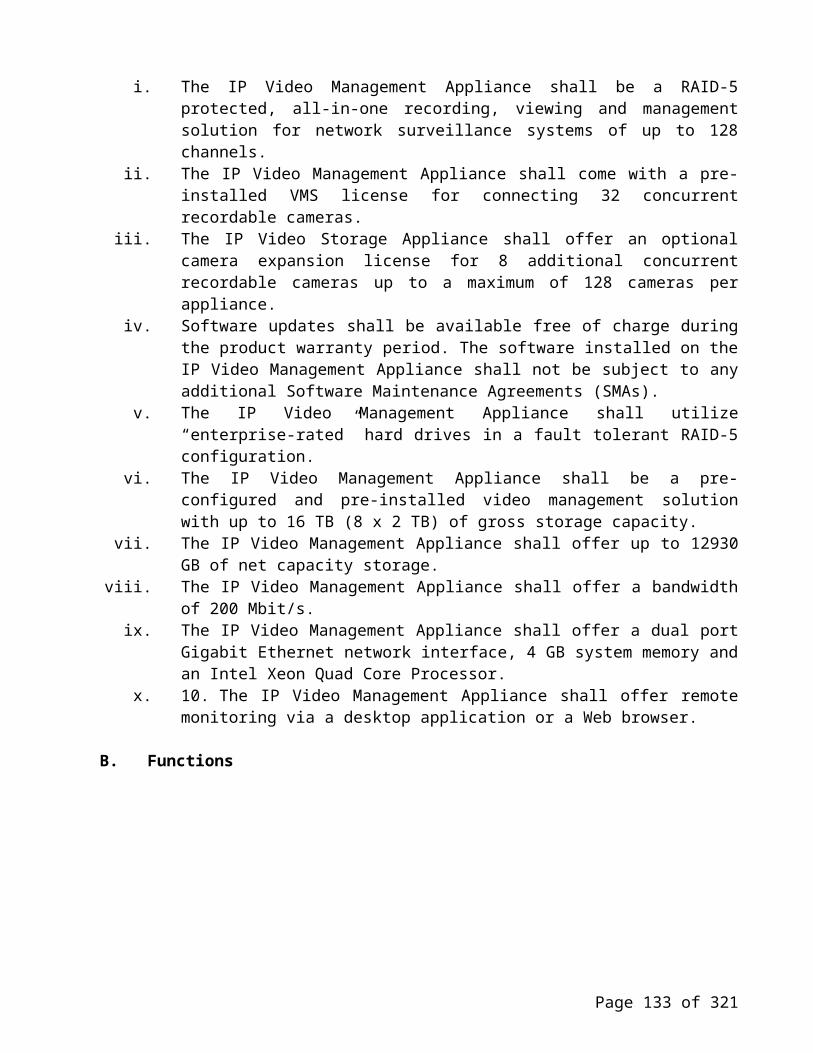
F. Probability of detection
The probability of detection (PD) for an intruder cutting the fence, and for unaided climbing attempts shall be 95% with a 95% confidence factor.
G. System-generated alarms (False alarms)
The maximum rate for alarms generated by internal electronic processes (cables excluded) shall be less than one per zone per year, averaged over the total number of zones in the system.
H. Zone length
The maximum length of each zone shall be 305 m of sensor cable. Individual zone length shall be determined by the physical boundaries of each zone. The sensor cable shall be supplied in rolls of 305 m and shall be cut to the correct length at the time of installation.
I. Gates
The sensor shall be capable of monitoring or bypassing swinging and sliding gates by using a Gate Bypass Module. The system shall be capable of placing monitored gates in access mode (no alarm when the gate is used), or secure mode within a secure zone, by either local or remote command. The status of the gate (secure or access) shall be communicated by relay contacts.
J. Distributed processing
The signal processors distributed along the perimeter shall receive and process the signals from the sensor cables while providing fail-safe operation. The failure of one processor shall not affect the signal processing of the other processors along the perimeter.
K. Total sensor cable length
Total sensor cable length shall be expandable from the 610m maximum using one signal processor to an unlimited length using multiple processors. The detection zone shall be continuous and uniform, and there shall be no gap between the individual zones, when installed in accordance with the manufacturer’s recommendations.
L. Alarm outputs
The digital signal processor shall identify intrusion, and supervision alarms locally by relay contacts. Each alarm zone shall include one intrusion alarm relay and one supervisory alarm relay. Each dual zone processor shall include four alarm output relays.
Alarms caused by climbing, cutting, or otherwise disturbing the fence fabric shall be identified as intrusion alarms. Intrusion alarms shall activate their respective alarm relay (zone 1 or zone 2) and shall be distinguished from supervisory alarms.Alarms caused by power failure, low input voltage, internal electronic fault, or opening the outer enclosure (tamper) shall be identified as supervisory alarms. These supervisory alarms shall activate both of the dual zone processor’s supervisory alarm relays. Alarms caused by cable faults shall be identified as supervisory alarms. Cable fault supervisory alarms shall activate their respective
Page 133 of 222

supervisory alarm relay (zone 1 or zone 2). Supervisory alarms shall be distinguished from intrusion alarms.
M. Reliability/maintainability
The signal processor shall have a mean time between failures (MTBF) of greater than 40, 000 hours and a mean time to replace (MTTR) of less than 10 minutes.
N. Physical installation criteria
When installed outdoors, the signal processor shall be mounted in a weatherproof, fiberglass, NEMA 4 rated enclosure. The processor shall be properly grounded with a user-supplied ground rod that is separate from the fence or pole upon which the processor is mounted. The enclosure shall include a hinged cover that is capable of being locked by a user-supplied pad lock. The enclosure shall include a tamper device. The enclosure shall include mounting feet that can be installed on the enclosure to suit the size and type of mounting pole or surface.
O. Mounting location
The enclosure shall be mounted on a wall, fence, or pole, separate from the fence on which the sensor cables are mounted, on the secure side of the perimeter.
P. Sensor calibration
Each sensor zone shall be capable of being calibrated from its respective signal processor. Sensor calibration shall be made using a configuration module, which shall allow the technician to adjust and monitor the response of each zone. The configuration module shall be detachable via a snap-in connector and shall be capable of calibrating each of the processors in the system. The configuration module shall receive power from the processor and shall not require batteries, calibration or maintenance. Accessing the snap-in connector shall require the opening of the processor’s enclosure. This action shall cause a tamper alarm to be generated.
Q. Calibration parameters
The following system parameters shall be adjustable by the user:o Cut detection: independent threshold, count and time per zoneo Climb detection: independent threshold, duration and time per zoneo Preamp gain: to match the fence to the sensor
R. Restricted calibration parameters
The following system parameters shall be adjustable by the user, through the use of a restricted pass-code. These parameters shall only require adjustment for highly specialized applications:
o Ambient compensation: enable/disable, level (for background effects)o Common mode rejection: enable/disable (for environmental effects)o Peak trigger value: to identify intrusion over backgroundo Cut profile value: to better define a cut event over environmental effectso Alarm output relay activation time: between 0.5 s and 5.0 s
Page 134 of 222

S. System installation and commissioning
The system shall be installed and commissioned in accordance with the manufacturer’s recommended procedures as defined in the product’s installation and setup guides.Prior to installation, the installer shall have completed a manufacturer’s training program and be certified by the manufacturer. Alternatively, the installer shall be required to have the manufacturer, or their designate, provide qualified technical support for installation and commissioning. Acceptance tests shall be performed in accordance with standard procedures available from the manufacturer.
T. Recalibration requirements
There shall be no need to recalibrate the system after initial calibration except as the fence condition deteriorates (loose fence elements or wires).
U. 4.2 Sensor cable repair
If the sensor cable is cut or damaged, it shall be capable of being repaired using additional cable, if required, and an appropriate splice kit. The splice kit shall require the use of only standard tools (i.e. slot screwdriver, wire strippers, wire cutters).
1.7 RAISED ACCESS FLOOR SYSTEM
A. System Description
Assemblies shall be composed of modular and self-supporting floor sub-structure bolted together, having gravity placed floor panels on top not connected to the pedestal supports. Lateral strength of floor system shall be independent from floor panels being in place, or fully removed.
Page 135 of 222

B. Performance Requirements
Structural Performance: Provide access flooring system capable of withstanding the following loads and stresses within limits and under conditions indicated, as determined by testing manufacturer's current standard test procedures:
i. Concentrated Loads: Provide 600x600mm floor panels, including those with cutouts, capable of withstanding a concentrated design load of 5000N, with a top-surface deflection under load and a permanent set not to exceed, respectively, 3.3 mm and 0.2 mm. If custom size floor panels are provided with a span of less or equal to 800 mm between secondary support beams, they need to comply with the above deflection and permanent set values as well, except if located under installed equipment cabinets or racks.
ii. Rolling Loads: Provide 600x600mm floor panels, capable of withstanding a rolling load of 6350N, with a top-surface deflection under load and a permanent set not to exceed, respectively, 3.3 mm and 0.2 mm.
iii. Uniform Distributed Loads: Provide self-supporting floor structure, without panels in place, capable of withstanding a minimum 10 kN/m2 uniform distributed load. For heavy equipment, which requires higher loading in accordance with the engineering drawing, the floor structure shall provide a uniform distributed loading capable of supporting the equipment for each individual case to avoid using separate equipment stands under Server racks or cabinets.
iv. Ultimate* Loads: Provide access flooring sub-structure system capable of withstanding a minimum ultimate concentrated load of 9070 N and a minimum ultimate distributed load of 39 kN/m2 without failing
* = max deflection of L/360 of span between beam sections
v. Pedestal Axial Load Test: Provide structure and pedestal assemblies, without panels in place, capable of withstanding a 40 500 N axial load per pedestal.
vi. Recycled content: Understructure system and floor panel shall be required to have a minimum recycled content of 75%.
*ESD-Control Properties: Provide floor coverings with ESD-control properties indicated as determined by testing identical products per test method indicated by an independent testing and inspecting agency.
Page 136 of 222

i. Antistatic Floor Covering Properties: Electrical Resistance: Test per EN 14041, 2004.
Greater than 50,000 ohms and an average value of less than 50.000 megohm when test specimens and installed floor coverings are tested surface to ground resistivity at a relative humidity of 50%.
.Static Generation: Max 100 V when tested at 50 percent relative humidity with conductive footwear.
* ESD: Electrostatic discharge. The transfer of electric charge between bodies at different potentials, from panel surface to ground.
C. PRODUCTS
a) Floor Panels, General: Provide modular panels complying with the following requirements that one person, using a portable lifting device, can interchange with other field panels without disturbing adjacent panels or understructure:
i. Nominal Panel Size: 600x600 mm. Custom size panels to be as specified based on engineering drawing.
ii. Fabrication Tolerances: Fabricate panels to the following tolerances with square ness tolerances expressed as the difference between diagonal measurements from corner to corner:
Size and Square ness: Plus or minus 0.38 mm of required size, with a squareness tolerance of plus or minus 0.38 mm, unless tolerances are otherwise indicated for a specific panel type.Flatness: Plus or minus 0.50 mm, measured on a diagonal on top of panel.
iii. Panel attachment to Understructure: By gravity. b) Wood-Core Panels with metal backside: Fabricate from 38 mm thick, V313 moist
resistant and E1 type particleboard core, made with <10 ppm urea formaldehyde. Laminate bottom aluminum face sheet with a direct laminate process using heat and pressure, providing a flame-spread index of 25 or less per ASTM E84 or NFPA 266. Provide tapered core edges including direct laminated surface finish of M335 Granite décor. All panel edges should be enclosed with a 0.45 mm glued perimeter ABS edge trim. Edge trim shall be applied so it covers the tapered panel edges, including surface finish. Provide custom panel sizes under equipment unless “open bottom access” is specified using a 38 mm steel tube under front and back of the equipment if shown on engineering drawings. Provide custom panels if shown on engineering drawings to assure all panels in service aisles or cooling aisles are fully removable.
c) Perforated Airflow Panels: Perforated Triad steel airflow panels designed for static loads of. shall be interchangeable with standard field panels and shall have 25% to 56% open surface area with the following air distribution capability:
d) Floor understructure: Assembly shall consist of 80x40 mm primary and secondary layer tube steel beam sections bolted together 90 degrees perpendicular to each other with angle clips and self tapping screws. Tube steel sections shall provide a
Page 137 of 222

yield and a tensile strength to meet the max allowed temporary deflection of L/360 of span. A distributed and concentrated static load calculation report shall be furnished for approval by certified structural engineer. All primary sections shall have a tension screw plate mounted to one side for tension against the perimeter wall. Provide “open bottom access” under the equipment racks using a square 38 mm steel tube under front and back of the equipment aisle if shown on engineering drawings.
e) Pedestals: Assembly consisting of base 80x40 mm tube column and head cap including head bracket with provisions for height adjustment, made of steel.
i. Base: Rectangular base with not less than 75 cm2. of bearing area.ii. Column: Of height required to bring finished floor to elevations indicated,
less 200 mm. Pressed securely into base plate and head cap. f) Provide vibration-proof leveling mechanism for making and holding fine
adjustments in height over a range of not less than +/- 25 mm and for locking at a selected height, so deliberate action is required to change height setting and vibratory displacement is prevented.
g) Head: Designed to support head bracket indicated which is attached to primary stringer.
Rust corrosion, metal components: All parts of the Floor under structure including Pedestal components shall be hot-dipped galvanized to ensure that no zinc particles will erode into the atmosphere.
h) Floor Panel Coverings General: Provide factory-applied direct laminate by raised access flooring manufacturer to top surface of floor panels. Standard Direct Laminate: Manufactured from phenolic and melamine resin impregnated papers, using a separate, high-wear type melamine glass overlay. Wear resistant to >6000 cycles according to EN 438-2:6 1991. Fabricate to cover each panel face prior to applying edge trim.
Page 138 of 222

i) Accessories i. Nail plugs: Manufacturer's standard nail plugs for securing pedestal bases to sub floor if
nothing else is shown on the engineering drawings. Glue should not be used.ii. Cutouts: Provide cutouts in floor panels for cable grommets and service outlets. Provide
reinforcement or additional support, if needed, to make custom size panels or cutouts to comply with standard performance requirements.
iii. Fit cutouts with manufacturer's standard grommets in sizes indicated or, if size of cutouts exceeds maximum grommet size available, trim edge of cutouts with manufacturer's standard plastic molding or edgetrim. Furnish removable covers for grommets if specified.
iv. Ramps: Manufacturer's standard ramp construction of width and slope indicated, but not steeper than 1:12, with non-slip floor covering to match the same performance and construction requirements as of the access flooring, or as indicated on the engineering drawings.
v. Railings: Standard extruded-aluminum railings, at ramps and open-sided perimeter of access flooring where indicated. Include handrail, intermediate rails, posts, brackets, end caps, wall returns, wall and floor flanges, plates, and anchorages where required, or as indicated on the engineering drawings.
vi. Panel Lifting Device: Manufacturer's standard portable lifting device of double type required for specified panels. Provide one lifting devices including wall mounted panel lifting bracket or a number as otherwise specified.
vii. Perimeter Support: Where indicated, provide manufacturer’s standard method for supporting panel edges and forming transition between access flooring and adjoining floor coverings. Perimeter support covering shall match floor panel finish(es), or as indicated on the engineering drawings.
D. EXECUTION
a) Examination i. Examine substrates, for compliance with requirements for installation tolerances and other
conditions affecting performance of work. ii. Verify that substrates comply with tolerances and other requirements specified in other
Sections and that substrates are free of cracks, ridges, depressions, scale, foreign deposits, and debris. Verify that concrete slab sub floor has been sealed.
b) Proceed with installation only after unsatisfactory conditions have been corrected. iii. Preparation
Lay out floor panel installation to keep the number of cut panels at floor perimeter to a minimum. Avoid using panels cut to less than 8 inches (200 mm). Complete any necessary sub floor preparation, and vacuum clean sub floor to remove construction debris before beginning installation.
c) Installation i. Install access flooring system and accessories under supervision of access flooring
manufacturer's authorized and certified representative to produce a rigid, firm installation that complies with performance requirements and is free of instability, rocking, rattles, and squeaks.
139

E. Installation, Phase I
i. Install primary beam sections supported by and mounted to pedestal assemblies so that no interference with feeder cables to and from equipment racks or cabinets occurs.
ii. Set pedestals with nail plugs as recommended by access flooring manufacturer to provide full bearing of pedestal base on sub floor.
iii. Level sub-structure pedestals supporting primary beam sections to permit panels be level and to proper height as set out in engineering drawings. Secure the leveling by tightening the locking nuts on all pedestals.
iv. Install secondary beam sections supported by primary beam sections using angle clips and self-tapping screws, so that they line up center to center with all panels in accordance with the manufacturers floor layout drawings.
v. Before installation phase II starts, perform cable management, electrical and HVAC installations under the floor substructure to prevent floor panels to be removed and reinstalled by subcontractors. By following this procedure, project schedule can be shortened and damage of floor panels be avoided.
F. Installation, Phase II
i. Install floor panels securely in place, properly seated with panel edges flush. Do not force panels into place. Verify if custom size panels are to be located in rows where equipment racks or cabinets of different depths are to be installed, to allow for service aisle panels to be fully removable.
ii. Scribe perimeter panels to provide a close fit with adjoining construction using foam tape between perimeter panel and wall, with no voids greater than 6 mm where panels abut vertical surfaces.
iii. Cut and trim access flooring and perform other dirt-or-debris-producing activities at a remote location, or as required to prevent contamination of sub floor under access flooring already installed.
iv. Ground flooring system as recommended by manufacturer and as needed to comply with performance requirements for electrical resistance of floor system and coverings.
v. Clean dust, dirt, and construction debris caused by floor installation, and vacuum sub floor area, as installation of floor panels proceeds.
vi. Install access flooring without change in elevation between adjacent panels and within the following tolerances:
Plus or minus 1.5 mm in any 3 meter distance. Plus or minus 3 mm from a level plane over entire flooring area. vii. Adjusting, Cleaning, And Protection
viii. Prohibit traffic on access flooring structure unless floor panels have been installed, or floor structure is covered by secure means to prevent accidents.
ix. After completing installation, vacuum clean access flooring and cover with continuous sheets of reinforced paper or plastic if required. Maintain protective covering until time of Substantial Completion.
x. Replace access floor panels that are stained, scratched, or otherwise damaged or that do not comply with specified requirements.
xi. After completed installation, inspect completed raised access floor installation together with customer using manufacturers standard “completed inspection form” and sign off for approval. Provide one copy to the customer and return one copy to manufacturer as a proof of completion and acceptance.
xii. After receipt of “completed inspection form”, manufacturer shall provide customer with a detailed warranty document dated and signed by authorized officer of the manufacturer.
140
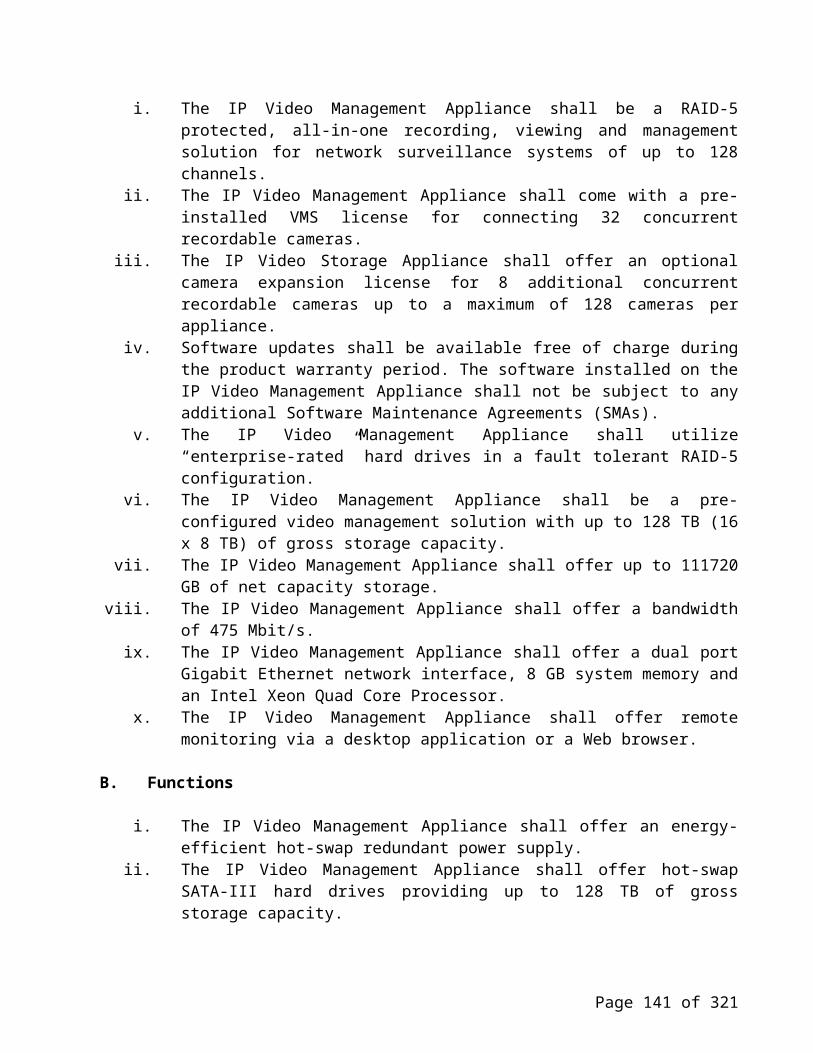
1.8 FIRE DETECTION SYSTEM
A. GENERAL REQUIREMENTS
i. The fire detection and alarm system shall comprise of main fire alarm control panels, optical smoke sensors, heat sensors, and optical smoke/heat sensor with integral sounder units, manual call points, electronic sounders, repeat panels, and interface units, each with its own short circuit built-in isolators. All loop cabling and any other components and accessories deemed necessary for a safe, reliable and satisfactory system will conform to the relevant and applicable requirements.
ii. Contractor will train and instruct client's personnel in the correct use, operation and supervision of the system, prior to the handing over of the project.
iii. The system will be configured to allow on site modifications with the minimum of disruption using the PC based software to facilitate future changes or alterations to the buildings.
B. SYSTEM DESCRIPTION
i. The fire detection and alarm system will be designed to facilitate accurate identification of the source of heat / smoke / fire in their early stages to minimize occurrences of false alarms due to faulty equipment, electrical transients, system faults etc.
ii. The fire alarm control panels will make final decision on whether a fire or fault exists by comparing the plotted patterns from a fire sensor against known fire and fault patterns held in its memory.
iii. System will be true Analogue with the ability to print the output from a fire sensor over a period of time.
iv. All system components and devices will be connected to two-wire loop circuits (as shown in the typical schematics) with each component having its own individual built-in isolator.
v. Removal or disconnection of any component from the loop will not affect the functioning and performance of other components and the system.
vi. System will be of safe addressable type i.e. all the devices on the loops of the FACP will be allocated addresses automatically from the panel at the time of system power up on a numerically lowest unused value basis (algorithms) and also given an address during commissioning, the value of which will be stored in non-volatile memory, within the electronics module of the outstation. This value will be read during loop allocation and provided it is valid will be used to setup the outstations primary address.
vii. SAFE Addressing will cover the benefits of Soft Addressing and also overcome the limitations of Hard Addressing. This means that if the devices are inserted or removed all the existing devices will keep the same address.
viii. The panel will allocate the address in strict sequential order when the loop is powered up to speed up commissioning and ensure that it is impossible for two devices to have the same address.
ix. Fire Detection and Alarm Systems, which rely only on soft addressing or hard addressing techniques, are not acceptable.
x. Facilities will be provided to constantly monitor and check the following circuits and fault conditions:
- The power supply to the loop /s; - For open-circuit, short-circuit, earth fault and any other fault condition in the loop wiring;- For communication failure and errors in all cards and loops- For faults in keyboard and printer circuits
141

- Monitoring of all devices status every 1.3 minutes to create a table of each 1 analogue channel for event analysis
xi. All devices Optical/Heat Sensor, Heat Sensor, Optical Smoke /Heat Sensor Sounder, Duct and Beam Sensors, Fire Alarm Interface Units, Electronic Sounders, Manual Call Points, etc. will be installed on the same loop.
xii. All devices will be assigned a maximum of 32-character alphanumeric label. In case of fire, fault or warning, the label of device sensing threshold will appear on visual display unit of the panel.
xiii. Any correction in label will have to be carried out from the built-in keyboard of FACP. Use of separate PC or tools for on-site programming will not be acceptable.
xiv. Any event i.e. Fire, fault or warning will be recorded with time, date and place of occurrence in the memory of FACP. These events can either be displayed on VDU or printed, as required.
xv. Provision will be done at the fire alarm control panels to silence the loop powered alarm sounders but the visual indication will remain until the system is reset.
xvi. It will be possible to change the sensitivity of analogue sensors from fire alarm control panel only.xvii. The sensitivity will be varied automatically, if required, by time zoning feature whereby it allows
sensors to be programmed to respond at different sensitivities relative to any time of day, and any day of week.
xviii. Facility to introduce / change delay periods in operating loop powered individual sounders / group of sounders /speaker circuits, will be possible to program from FACP without the need to change any hardware.
xix. The main fire alarm control panels will be located as shown on the schematics and the floor drawings.
C. SYSTEM OF OPERATION
In the event of a fire being reported from the smoke/heat Detectors, activation of manual call points or sprinkler operation the sequence of alarm operation will be as follows:
i. If a fire condition is reported from a smoke or heat detector, Manual Break Glass, or sprinkler flow switch , then the evacuation alarm tone will be done by the electronic sounders in the same zone. Then after a certain delay (to be agreed at the time of commissioning) or after 3 minutes the alarm has not been acknowledged, the evacuation tone from the sounders will activated in the adjacent fire zones. Or on the floor directly above and below. All other floors or zones will be given the Alert tone . The evacuation of the building will be staged in phases to allow orderly movement of people.
Activation of the fire alarm system will directly initiate some or all of the following to be agreed as a part of the overall engineering policy.
• Signal to all elevator machine rooms indicating fire status (to control lifts)• Release doors normally locked by magnetic devices.• Release doors normally held open by magnetic devices• Shutdown mechanical equipment ventilation plant• Shutdown general exhaust fans• Start up smoke extract fans• Start up exhaust make up fans• Start up stair vestibule pressurization fans• Automatically operate fire dampers
142

ii. Sprinkler valves, flow switches and other monitored valves will be directly supervised by the fire alarm systems to other systems.
D. SYSTEM, COMPONENTS AND DEVICES.
i. The panel will be computer controlled using analogue technique to detect smoke / heat / fire conditions. The panel will be complete with, but not limited to, the following elements:
Visual display unit capable of displaying LCD Alphanumeric 40 characters x 8 line display minimum backlit display.
Built-in 40-character thermal printer operating when the access door is open there will also be an option to enable the printer when the door is closed.
Built-in full QWERTY keyboard. Labelling of devices will be done from this keyboard. Also, this keyboard if required will do any correction in label and onsite programming & maintenance.
Integral rechargeable sealed lead acid battery and charger, with 24-hour back up in the event of supply mains failure.
Essential controls - sound alarms, silence alarms and reset fire. These will be enabled by a key switch.
Cancel fault buzzer Fire, fault, warning and power on lamps. Simple menu driven function keys with password protection will allow users to an extensive range of
software based features such as:- Last 100 fire events- Last 255 system events- Current fault and warning logs.- Analysis of analogue sensor information- Interrogation of sensor cleanliness- Loop map connections- Enable/ disable sensors, zones, sounders, interface unit channels.- Fire plan configuration menus- Outstation label changes - Address allocation- Status of outstation- Status of all cards- Printer on, off, line feed and test facilities.- Address allocation including SAFE addressing.
All control buttons and keyboard will be enclosed behind a lockable cover. Up to 200-device capacity per 1km loop. RS 232/ RS 485 computer communication option. Will have minimum of 2 Master alarm circuits 24V 400Ma max per circuit. Will have a secure networking facility to indicate a remote zone and remote zone text across the
network.
ii. Sensors:
All analogue sensors and bases shall be provided by the manufacturer of the control equipment. The sensor bases for interfacing between the loop wiring and the sensor head shall not contain any electronics. The base
143

fixings should be suitable for SA industry standard or conduit boxes. All bases shall have the necessary connections for sending repeat fire signals to a remote LED unit.
The sensors provided shall be lockable into position if required and removal of locked sensors shall be achievable only through the use of the appropriate removal tool. Sensor removal tools should be provided on completion of the contract as part of the spare parts profile. The removal of a sensor from its base shall not affect the continuity of the detection loop.
The following types of analogue sensors will be available as standard:
• Heat sensor• Optical Heat sensor• Beam sensor (transmitter and receiver) with 7 programmable sensitivity settings
All of the above shall be compatible with the aforementioned base providing inter-changeability between sensor heads without the requirement for switch settings. All sensors will also have an integral short circuit isolator, which in the event of a single cable fault will isolate the faulty section of cable and retain all devices on the loop operationally in less than 1 second.
The sensitivity off all sensors will be adjustable from the control panel. This may be carried out manually to manage false activation issues or automatically using the system clock i.e. day/night settings for specific risks. It shall be possible to programme sensors within a range of sensitivity levels from State 0 (high level) through to State 15 (disabled).
Each sensor will possess an integral Red LED giving a flashing indication of a fire signal or a continuous indication for certain fault conditions. The integral LED can also be enabled/disabled to provide operational status i.e. short flashes that indicate the unit is powered and communicating with the control panel.
iii. HEAT SENSORS
They will be complete with the other elements described for smoke sensors above, for an analogue safe addressable sensing device.Sensors mounted in the false ceilings will be provided with a semi flush mounting kits. & it shall have inbuilt short circuit isolator
iv. BEAM SENSORS
The Beam Sensors will be safe addressed, loop powered, loop signalled with built in short circuit isolator and compact and will detect fire by obscuration of an optical beam by smoke. It will utilize a transmitter and receiver unit and be suitable for ranges of up to 100m. It will be used in areas as indicated in the drawings. The traditional false alarm problems associated with the use of beam detection, such as birds, workmen and sunlight will be overcome by the use of True Analogue Detection.
A method of automatic gain control will be employed to minimize the effects of a build-up of dust and dirt on the lens. LEDs will be provided integral with the transmitter/receiver units to assist in the alignment set-up.
144

v. DUCT SENSORS
Duct Sensors will be safe addressed, loop powered, loop signalled with an inbuilt short circuit isolator. They will comprise of a sampling unit with probes extending into a straight section of the mechanical ventilation ductwork. The duct sensor will comprise of Optical Smoke/Heat Sensing devices. & it shall hav inbuilt short circuit isolator
vi. Manual Call Points:
The manual call points shall be electrically compatible with all of the aforementioned sensor types. Each device shall contain its own microprocessor giving a 1 second response time from initiation. The MCP shall be available as a semi-flush mounting unit fixing to a standard single gang recessed box or as surface mounting unit on a matching red plastic back box.
The MCP will have the ability to be tested functionally without the need to remove the front cover or breaking the glass with a special test key (supplied as standard). The key shall insert in the front facia of the MCP ensuring easy access of the key at all times. The key will also be used to reset the MCP when fitted with a resettable plastic element. The option to retrofit a clip-on transparent plastic cover to prevent accidental or malicious activation should be available as standard and give the unit an IP55 ingress rating when fitted to the plastic back box.
vii. ALARM SOUNDERS
Alarm Sounders are all Electronic sounders Addressable and loop powered and Standard Evacuate & Alert tone with voice messaging Programmable tones selectable by control panel. Synchronisation of all sounders to be fully synchronised with all other analogue addressable loop powered sounder speech devices on the system.
The safe addressable Alarm Sounders will be loop wired and loop signalled and provided with built-in short circuit isolation and will be sited in the emergency stairwell staff/utility areas and plant rooms. The sounders will be configured via software to operate individually or in sectored groups, totally independent of the way they have been connected to the loops. The sounders will have the synchronization feature to ensure that all the sounders give alert and evacuate tones that are totally in phase. Conventional Sounders that "free-run" and therefore be out of phase with each other will not be accepted.
The Sounders will have Minimum sound pressure level 103 dBA at 1 metre with frequencies of 970 Hz and 910 Hz. Variety of sounds will be available.
viii. Interface Modules:
Fire detection interface units will be directly connected to the loop to provide both inputs and outputs for the control or annunciation of other life safety, security and building management systems. These units shall be either self-contained wall mountable units or DIN rail mounting units for fitting within 3rd party control equipment/panels. Each device will incorporate a short circuit isolator as standard to maintain system integrity in the event of an equipment failure or wiring fault. As standard six variants will be available:
(i) 4 channel input and/or output interface(ii) 1 channel Low Voltage input/output interface(iii) 1 channel Low Voltage input only interface
145

(iv)Mains Voltage 240V 13A switched output interface(v) Mains powered 4 channel interface with monitored integral power supply unit, battery standby and 250mA output circuits(vi)Key switch operated single channel interface
E. INSTALLATION
i. Fire alarm components will be installed directly to conduit outlet boxes at the following mounting heights above finished floor level, measured to the centre of box unless stated otherwise.
ii. Fix manual call station semi-recessed at 1.5m. heights above finished floor.iii. Automatic smoke and heat sensors: Ceiling mountediv. Alarm sounders: 2.20m above finished floorv. Outdoor alarm: fix where indicated by fire dept. and approved by the Client / Consultant engineer.
vi. External response indicators: fix beside or above doors as directed by the client engineer / as shown on the drawings.
F. WIRING AND WIRING FACILITIES:
i. Supply and install the necessary conduit, enclosed trucking to the Fire Cable and accessories and wiring for the fire alarm system.
ii. All cables associated with Fire Alarm installation will be of fire resistant 2 core 1.5 sq. mm.iii. Multi core cables having more than 2 cores will not be allowed for loop wiring due to inadequate
separation and possible interference problems.iv. All wiring will be installed to provide complete and satisfactory function system in all respects. v. All cable terminations at components and junction boxes will have identification tags, indicating
throughout the system.vi. The Fire Alarm/Detection system wiring will be completely independent from the other system
wiring in all respects in accordance with the IEE Regulations.
G. TESTING AND COMMISSIONING
i. After the installation is complete, the contractor will conduct operating and commissioning tests. ii. The equipment will be demonstrated to operate in accordance with the requirements of the
specification. iii. The system installation, testing and commissioning will be as per Local approvals and requirements.iv. The fire alarm system will be completely programmed in accordance with Fire Department
requirement.v. A company trained representative will personally supervise the complete installation and final testing
of the system.vi. All tests will be carried out in the presence of the Client or persons authorized by the consultant /
client. vii. Upon the completion of the acceptance tests, the representatives will instruct operatives in the proper
operation, maintenance programming, configuration, and testing of the system. viii. The vendor will provide equipment and /or software which is necessary to allow field modification of
the programming and configuration.
146

1.9 FIRE SUPPRESSION SYSTEM
1.9.1 SYSTEM DESCRIPTION
a) The system shall be a Total Flood FM-200 Suppression System.b) The system shall provide a FM-200 minimum design concentration of 7.2% by volume for Class A
hazards and 9.0% by volume for Class B hazards, in all areas and/or protected spaces, at the minimum anticipated temperature within the protected area.
c) System design shall not exceed 10.5% for normally occupied spaces, adjusted for maximum space temperature anticipated, with provisions for room evacuation before agent release.
d) The system shall be complete in all ways. It shall include all mechanical and electrical installation, all detection and control equipment, agent storage containers, FM-200 agent, discharge nozzles, pipe and fittings, manual release and abort stations, audible and visual alarm devices, auxiliary devices and controls, shutdowns, alarm interface, caution/advisory signs, functional checkout and testing, training and all other operations necessary for a functional, UL Listed and/or FM approved FM-200 Clean Agent Suppression System.
e) Provide two (2) inspections during the first year of service. Inspections shall be made at 6-month intervals commencing when the system is first placed into normal service.
f) The general contractor shall be responsible for sealing and securing the protected spaces against agent loss and/or leakage during the 10-minute "hold" period.
g) The system shall be actuated by a combination of ionization and/or photoelectric detectors installed for maximum area coverage of 23.2 m2 per detector, in both the room, underfloor and above ceiling protected spaces. If the airflow is one air change per minute, photoelectric detectors only shall be installed for maximum area coverage of 11.6 m2 per detector.
h) Detectors shall be Cross-Zoned detection requiring two detectors to be in alarm before release.i) Automatic operation of each protected area shall be as follows: Actuation of one (1) detector, within the system, shall:
Illuminate the "ALARM" lamp on the control panel face. Energize an alarm bell and/or an optional visual indicator. Transfer auxiliary contacts which can perform auxiliary system functions such as: i) Operate door
holder/closures on access doors, ii) Transmit a signal to a fire alarm system, iii) Shutdown HVAC equipment.
Light an individual lamp on an optional annunciator. Actuation of a 2nd detector, within the system, shall:
Illuminate the "PRE-DISCHARGE" lamp on the control panel face. Energize a pre-discharge horn or horn/strobe device. Shut down the HVAC system and/or close dampers. Start time-delay sequence (not to exceed 60 seconds). System abort sequence is enabled at this time. Light an individual lamp on an optional annunciator.
After completion of the time-delay sequence, the FM-200 Clean Agent systemshall discharge and the following shall occur:
Illuminate a "SYSTEM FIRED" lamp on the control panel face. Shutdown of all power to high-voltage equipment Energize a visual indicator(s) outside the hazard in which the discharge occurred. Energize a "System Fired" audible device. (Optional)
The system shall be capable of being actuated by manual discharge devices located at each hazard exit. Operation of a manual device shall duplicate the sequence description above except that the time
147

delay and abort functions shall be bypassed. The manual discharge station shall be of the electrical actuation type and shall be supervised at the main control panel.
1.9.2 MATERIALS AND EQUIPMENT
A. GENERAL REQUIREMENTS
i. The FM-200 Clean Agent System materials and equipment shall be standard products of the supplier's latest design and suitable to perform the functions intended.
ii. When one or more pieces of equipment must perform the same function(s), there shall be duplicates produced by one manufacturer.
iii. All devices and equipment shall be UL Listed and/or FM approved.iv. The gas shall display the following properties:
Remove heat energy from fire, not oxygen from the environment. Absorb heat from the flame zone and interrupts the chemical chain reaction of the combustion
process. Be a Low-pressure gas system. Have a low toxicity level. Shall not displace oxygen and therefore is safer for use in occupied spaces without fear of
oxygen deprivation. Shall have been proven safe for people. Shall contain no bromine or chlorine and therefore has zero Ozone Depleting Potential
(ODP). Be effective in the protection of data processing, telecommunications and electronic
equipment as well as most flammable liquids and gases. Shall be clear and not obscure vision. Require minimal container storage space Extinguish fires quickly through a combination of chemical interaction and physical heat
removal. Provide rapid suppression with a short discharge time of typically 6 to 10 seconds. Be a clean gaseous agent leaving no residue. Be a low pressure gas
B. FM-200 AGENT STORAGE AND DISTRIBUTION
i. Each system shall have its own supply of clean agent.ii. The system design can be modular, central storage, or a combination of both design criteria.
iii. Systems shall be designed in accordance with the manufacturer's guidelines.iv. Each supply shall be located within the hazard area, or as near as possible, to reduce the amount of
pipe and fittings required to install the system.v. The clean agent shall be stored in the manufacturer’s Storage Containers.
vi. Containers shall be super-pressurized with dry nitrogen to an operating pressure of 24.8 bar at 20oC.vii. Containers shall be of high-strength low alloy steel construction.
viii. Containers shall be actuated by a resettable electric actuator with mechanical override located at each agent container or connected bank of cylinders.
ix. Non-resettable or explosive devices shall not be permitted.x. Each container shall have a pressure gauge and low-pressure switch to provide visual and electrical
supervision of the container pressure.
148

xi. The low-pressure switch shall be wired to the control panel to provide an audible and visual "Trouble" alarms in the event the container pressure drops below (17 bar).
xii. The pressure gauge shall be colour coded to provide an easy, visual indication of container pressure.xiii. Each container shall have a pressure relief provision that automatically operates before the internal
pressure exceeds 51.7 bar.xiv. Engineered discharge nozzles shall be provided within the manufacturer’s guidelines to distribute the
FM-200 agent throughout the protected spaces. xv. The nozzles shall be designed to provide proper agent quantity and distribution.
Nozzles shall be available in 10 mm through 50 mm pipe sizes. Each size shall be available in 180o
and 360o distribution patterns. Ceiling plates can be used with the nozzles to conceal pipe entry holes through ceiling tiles.
xvi. Distribution piping, and fittings, shall be installed in accordance with the manufacturer's requirements, and approved piping standards and guidelines.
xvii. All distribution piping shall be installed by qualified individuals using accepted practices and quality procedures.
xviii. All piping shall be adequately supported and anchored at all directional changes and nozzle locations. All piping shall be reamed, blown clear and swabbed with suitable solvents to remove burrs, mill
varnish and cutting oils before assembly. thread only. All pipe threads shall be sealed with Teflon tape pipe sealant applied to the male
C. CONTROL PANEL
i. The control system and its components shall be UL listed and FM approved for use as a local fire alarm system with releasing device service.
ii. The control system shall perform all functions necessary to operate the system detection, actuation and auxiliary functions.
iii. The control system shall include battery standby power to support 24 hours in standby and 5 minutes in alarm.
iv. The control system shall be microprocessor based utilizing a distributed processing concept. A single microprocessor failure shall not impact operation of additional modules on the system.
v. The control system shall be capable of supporting Cross Zoned Detection.vi. The control system shall supply integrated 2Amp power supply circuitry.
D. MANUAL RELEASE (Electric)
i. The electric manual release switch shall be a dual action device which provides a means of manually discharging the Suppression System when used in conjunction with the control system.
ii. The Manual Release switch shall be a dual action device requiring two distinct operations to initiate a system actuation.
iii. Manual actuation shall bypass the time delay and abort functions shall cause the system to discharge and shall cause all release and shutdown devices to operate in the same manner as if the system had operated automatically.
iv. A Manual Release switch shall be located at each exit from the protected hazard.
E. AUDIBLE and VISUAL ALARMS
i. Alarm audible and visual signal devices shall operate from the control panel.ii. A Strobe device shall be placed outside, and above, each exit door from the protected space.
iii. Provide an advisory sign at each light location
149

F. CAUTION and ADVISORY SIGNS
Signs shall be provided to comply with regulation, standards and the recommendations of the FM-200 equipment supplier.
i. Entrance sign: (1) required at each entrance to a protected space.ii. Manual discharge sign: (1) required at each manual discharge station.
iii. Flashing light sign: (1) required at each flashing light over each exit from a protected space.
G. SYSTEM and CONTROL WIRING
i. All system wiring shall be furnished and installed by the contractor.ii. All wiring shall be installed in electrical metallic tubing (EMT), or conduit, and must be installed and
kept separate from all other building wiring.iii. All system components shall be securely supported independent of the wiring.iv. Runs of conduit and wiring shall be straight, neatly arranged, properly supported, and installed
parallel and perpendicular to walls and partitions.
H. TESTING AND DOCUMENTATION
i. After the system installation has been completed, the entire system shall be checked out, inspected and functionally tested by qualified, trained personnel, in accordance with the manufacturer's recommended procedures.
ii. All containers and distribution piping shall be checked for proper mounting and installation.iii. All electrical wiring shall be tested for proper connection, continuity and resistance to earth.iv. The complete system shall be functionally tested, in the presence of the owner or his representative,
and all functions, including system and equipment interlocks, must be operational at least five (5) days prior to the final acceptance tests.
v. Each detector shall be tested in accordance with the manufacturer's recommended procedures, and test values recorded.
vi. All system and equipment interlocks, such as door release devices, audible and visual devices, equipment shutdowns, local and remote alarms, etc. shall function as required and designed.
vii. Each control panel circuit shall be tested for trouble by inducing a trouble condition into the system.
I.TRAINING REQUIREMENTS
i. Prior to final acceptance, the installing contractor shall provide operational training to each shift ofthe owner’s personnel.
ii. Each training session shall include control panel operation, manual and (optional) abort functions, trouble procedures, supervisory procedures, auxiliary functions and emergency procedures.
J. OPERATION and MAINTENANCE
i. Prior to final acceptance, the installing contractor shall provide complete operation and maintenance instruction manuals, 3 copies for each system, to the owner.
ii. All aspects of system operation and maintenance shall be detailed, including piping isometrics, wiring diagrams of all circuits, a written description of the system design, sequence of operation and drawings illustrating control logic and equipment used in the system.
150

iii. Checklists and procedures for emergency situations, troubleshooting techniques, maintenance operations and procedures shall be included in the manual.
K. AS-BUILT DRAWINGS
i. Upon completion of each system, the installing contractor shall provide 3 copies of system "As-Built" drawings to the owner.
ii. The drawings shall show actual installation details including all equipment locations (i.e.: control panel(s), agent container(s), detectors, alarms, manuals and aborts, etc.) as well as piping and conduit routing details.
iii. Show all room or facilities modifications, including door and/or damper installations completed. iv. One (1) copy of reproducible engineering drawings shall be provided reflecting all actual installation
details.
L. ACCEPTANCE TESTS
i. At the time "As-Built" drawings and maintenance/operations manuals are submitted, the installing contractor shall submit a "Test Plan" describing procedures to be used to test the control system(s).
ii. The Test Plan shall include a step-by-step description of all tests to be performed and shall indicate the type and location of test apparatus to be employed.
iii. The tests shall demonstrate that the operational and installation requirements of this specification have been met.
iv. All tests shall be conducted in the presence of the owner and shall not be conducted until the Test Plan has been approved.
v. The tests shall demonstrate that the entire control system functions as designed and intended. vi. All circuits shall be tested: automatic actuation, solenoid and manual actuation, HVAC and power
shutdowns, audible and visual alarm devices and manual override of abort functions. vii. Supervision of all panel circuits, including AC power and battery power supplies, shall be tested and
qualified.viii. A room pressurization test shall be conducted, in each protected space, to determine the presence of
openings which would affect the agent concentration levels. ix. If room pressurization testing indicates that openings exist which would result in leakage and/or loss
of the extinguishing agent, the installing contractor shall be responsible for coordinating the proper sealing of the protected space(s).
x. The contractor shall be responsible for adequately sealing all protected space(s) against agent loss or leakage.
xi. The contractor shall inspect all work to ascertain that the protected space(s) have been adequately and properly sealed.
xii. THE SUPPRESSION SYSTEM INSTALLING CONTRACTOR SHALL BE RESPONSIBLE FOR THE SUCCESS OF THE ROOM PRESSURIZATION TESTS.
xiii. If the first room pressurization test is not successful, in accordance with these specifications, the contractor shall to determine, and correct, the cause of the test failure.
xiv. The contractor shall conduct additional room pressurization tests, at no additional cost to the owner, until a successful test is obtained.
xv. Copies of successful test results shall be submitted to the owner for record. xvi. Upon acceptance by the owner, the completed system(s) shall be placed into service.
M. SYSTEM INSPECTIONS
151

i. The installing contractor shall provide two (2) inspections of each system, installed under this contract, during the one-year warranty period.
ii. The first inspection shall be at the six-month interval, and the second inspection at the 12-month interval, after system acceptance.
iii. Inspections shall be conducted in accordance with the manufacturer's guidelines and the recommendations of SANS.
iv. Documents certifying satisfactory system(s) operation shall be submitted to the owner upon completion of each inspection.
N. WARRANTY
The system components furnished and installed under this contract shall be warranted against defects in design, materials and workmanship for the full warranty period which is standard with the manufacturer, but in no case less than one (1) year from the date of system acceptance.
1.10 INTERCOM SYSTEM
1.10.1 General
i. Fully digital, distributed network-based IP-intercom system (LAN/WAN). Easy setup/update/maintenance via PC software or Web browser with password.
ii. Connection of standard receivers from two-wire cable to the mediation unit or the IP stations across the network.
iii. Links allow quantization with a sampling rate of 16 kHz for a 16-bit a high-quality sound with a frequency range of 300 Hz to 7 kHz at full-duplex conversations. Hands-free calling is possible through ECHO suppression in this quality.
iv. Programmable intercom functions:v. Call, announcements, speed dial, manual call forwarding, automatic call forwarding, time-based call
forwarding, adjustable time limitation for discussions, announcements and ringtone, manual activation of control outputs, automatic activation of control outputs (E.g. camera activation with reputation), automatic call activation control input, group call, call forwarding to "Busy", Office - call forward unconditional (time adjustable), auto answer, classic answer, automatic direct dial at the receiver, priority call, call Priority announcement priority, choice of up to 8 sources of background music, adjustable microphone sensitivity, Ringer volume, speaker volume.
vi. Distribution of stations in up to 160 zones. Call announcement up to 160 call zones / 1279 receivers at the same time possible. Grouping with customizable access rights regarding call and announcement permissions of the groups themselves.
vii. Ability to customize the bandwidth of a connection of 48.5 kbps up 130 kbps on the available network capacity.
viii. Automatic system diagnosis (every 20 seconds) of receivers, teaching units, IP Intercoms and universal interface for the network status, CPU errors, synchronization problem and missing receivers.
ix. Error signalling by freely programmable control output.x. Monitoring / system information via Web browser: Access / change network settings, monitor
network status, status / action monitoring receivers, operational log (LOG), data stream Protocol (LOG), firmware update, reboot, change system name and password
xi. Possibility of recording conversations through establishment of a PC-based recording software.xii. Remote control of receivers with a PC through a software setup.
152

xiii. Depending on the system configuration, receivers, 1280 control inputs, 1280 control outputs, 160 audio inputs and 160 audio outputs can be operated up to 1280
1.10.2 Audio Server
i. Fully digital IP mediation unit with connections for 16 stations. Connection to other teaching units, universal interface and IP intercom stations on a network. Connecting the stations in 2-wire technique.
ii. No separate power supply of needed receivers. 1 internal and 2 external communication channels are also available.
Programmable functions:iii. Call, announcements, speed dial, manual call forwarding, automatic call forwarding, time-based call
routing, adjustable time limitation for discussions, announcements and ringtone, automatic activation of control outputs (E.g. call door intercom - CCTV via contact output activation), automatic call activation control input, group call, call forwarding to "Busy", Office - call forward unconditional (time adjustable), auto answer, classic answer, automatic direct dial at the receiver, priority call, choosing from up to 8 sources of background music, adjustable microphone sensitivity, ringer volume, speaker volume.
iv. Additional grouping with customizable access rights regarding call and announcement permissions of the groups themselves.
v. 3 Status LED indicators for: operation, status, network.
1.10.3 IP Desktop Master Station with Display & Handset
i. Multifunctional master station with handset and speakerphone with ECHO compensator, LCD display with 16 characters, 2 lines, 8 programmable direct dial keys, connection for headset connection of external speaker, menu functions.
ii. 10 Buttons, 4 programmable speed dial buttons, 2 function keys, talk priority button, delete button, call button (for announcement), answer key (for announcement), hold-down button, transfer button (manual call forwarding), redial.
iii. Function call button for activation control output, call forwarding, Office transfer, time-based call forwarding, busy forwarding, background music.
iv. Programming the direct dial keys (follow)v. Indicator connected stations at mediation unit
vi. Update function of the operation log (log file), change the IP address, subnet mask, default gateway of the mediation unit with password protection. Setting the system clock, system restart.
1.10.4 Sub-station IP with 1 Button
i. IP door intercom for direct connection to the network, speakerphone with echo cancellation, call button, control output (E.g. the door opening), dust and water protection com. IP54, extended working temperature range.
1.11 SECURITY FENCE PERIMETER LIGHTING
i. Lamps used in the security fence perimeter lighting system shall be of the compact fluorescent type to ensure instant cold and hot re-strike.
153

ii. The security fence perimeter fence lighting system shall consist of a streetlight luminaire, equipped with two 26watt compact fluorescent lamps and mounted at a rake angle of 15 above the horizontal and at 6 metres above ground level on a GRP/galvanised steel pole positioned 2m inside the outer fence.
iii. The spacing shall be in such a way as to achieve an average initial illumination level of 5 lux and a minimum initial illumination level of 3 lux in the area of the fence line.
iv. The streetlight type luminaire circuit shall be controlled by a photoelectric cell.
1.12 EARTHING SYSTEM
1.12.1 Earth-termination Rods (Copper, 14.3 mm in diameter, 1.2m with clamp)
a) General
To ensure compatibility of component parts of the earth rod assembly, the items to be supplied shall consist of earth rods and accessories which form a "total system" (but excluding connectors and earthing enhancing compounds). This will include an assessment of the safety, productivity, reliability and longterm performance of the items.The design of the rod assembly (including couplings and driving points) shall be of such mechanical strength that they shall withstand the stresses and abrasions present during installation with an electric/pneumatic hammer.The design of the rods and couplings shall be such that during installation, the connection between the rod and the coupling shall "self-tighten". This self-tightening shall have the effect of improving the electrical and mechanical performances of the rod/coupling combination.The Tenderer shall state the design features of the rod and accessories which verify the following features:
Self-tightening Improved electrical connection No damage to the copper sheath on installation.
The rod system shall be extendable by the use of appropriate couplings.All items including rods, couplings, driving tips, driving caps and connectors shall be clean, free of burrs, cracks and sharp edges. The ends of the rods shall be chamfered.Methods of covering the top of the earth rod at each earthing installation. The application of such a covering shall protect against corrosion of the earth rod. The covering does not have to meet any specific criteria eg. UV-stabilised.Recommended procedure for the correct assembly of the various components of the earthing, system including the earth rod, coupling, driving mechanism, driving points and connectors.
b) Rods – General
The earth rods shall have a nominal outside diameter of 13 mm and a nominal length of 150 mm. The rod shall consist of a steel core of minimum grade AS 3679.1-250.The copper sheath shall be either molecularly bonded or extruded so as to maintain intimate contact with the steel core of the earth rod. The application of the copper sheath shall prevent any electrolytic action to be initiated by moisture ingress between the copper and the steel.Tenderers shall state the method used to apply the copper sheath to the rod together with the design features to verify the prevention of moisture ingress.Extruded sheath rods shall have a final minimum thickness of copper of 0.45 mm.Rods which have the copper applied electrolytically, shall have a minimum copper thickness of 0.25 mm.
154

Rods shall be “tapered" type complying with the clauses described below.
NOTE: Threaded rods are NOT acceptable.
c) Rods – Tapered
Both ends of the rods shall be tapered. The taper shall be approximately 3:100 on diameter and the length of taper shall be at least 50 mm long (as measured parallel to the axis of the earth rod).
d) 5.4 Couplings
i. The coupling device shall be designed to ensure good permanent electrical conductivity is maintained between the joined earth rods throughout a service life of 35 years for the installed earth rod assembly.
ii. The couplings shall be manufactured from material compatible with the rods. The material used shall be selected to ensure that electrolytic action and/or stress corrosion cracking will not occur. In addition, the surfaces of the couplings exposed to the soil, shall be corrosion resistant.
e) 5.5 Driving Point
i. The driving points shall be designed to reduce the driving effort on the earth rod. The driving point shall be designed to prevent damage to the copper sheath during the installation process.
ii. Both "Normal" and "Star" (rock) type driving points are required. The diameter of both types of driving points must NOT be LESS THAN the diameter of the earth rod/coupler assembly.
f) Driving Mechanism (Head + Pin as applicable)
The driving mechanism shall be used in conjunction with an electric/pneumatic hammer.The driving mechanism shall cover the rod sufficiently so as to prevent it from bouncing off the rod when used in conjunction with an electric/pneumatic hammer.The driving head shall not damage the copper coating of the earth rod. Further, the driving mechanism shall not distort the coupling and/or rod to such an extent that an additional earth rod cannot be fitted into the coupling.Full details concerning the method of installation including:
• The removability of the driving pin and/or the last coupling when the installation process is completed
• The requirement for a coupling for driving purposes.The extent of re-useability of the driving pin and the coupling.
g) Compression Connectors
i. Connector(s) shall satisfy the following requirements:Be suitable for direct burial in the ground.Connect a 13 mm diameter rod with a stranded copper conductor of the following sizes :-Minimum conductor size: 50 mm² (19/1.78)Maximum conductor size: 70 mm² (19/2.14)Be used to join the following stranded copper conductors:50 mm² to 50 mm²
155

50 mm2 to 70 mm²70 mm² to 70 mm²
The same method of connection shall be used for a conductor/conductor joint as well as a conductor/rod joint.
ii. The "C" shaped compression fitting is the preferred compression type connector.iii. The design of the connector shall allow the laying of two cables side by side when making aiv. Conductor / conductor connection.v. Some form of anti-oxidant grease covering the inside of the connector is required for
compression type fittings.vi. Indicate if the rod requires pre-crimping prior to compressing the connector.
h) Bolted Connectors
i. Connectors (Earth Rod/Conductor) shall satisfy the following requirements:• Be suitable for direct burial in the ground.• Be suitable for connecting a 13 mm diameter rod with one or two stranded copper conductors
of the following sizes:Minimum conductor size: 35 mm² Maximum conductor size: 70 mm²
ii. Be of double saddle type that houses the conductor and earth rod separately.iii. Be of materials which are resistant to corrosion and parts of the connector which are in direct
contact with the conductor and earth rod shall be of material which does not cause interface corrosion.
iv. The Connectors (conductor/conductor) shall satisfy the following requirements:• Be suitable for underground applications and shall have corrosion resistant properties similar
to the 'earth rod/conductor' type connectors• The Connectors (conductor /conductor) shall be suitable for joining the following types of
stranded copper conductor;35mm2 to 35 mm²35mm2 to 70 mm²70mm2 to 70 mm²
v. The connectors shall be supplied with copper M10 nuts vi. All bolts and washers shall be copper.
vii. All nuts shall be copper.viii. Copper bolts and nuts shall be suitably greased to prevent binding
ix. Advise the minimum and maximum recommended tightening torques as well as the specified tightening technique/procedure.
i) Technical Characteristics
i. Tenderers shall provide detailed drawings for all items tendered.
j) Performance and Testing
Connectors
i. Connectors shall be installed in accordance with the manufacturer’s instructions.ii. The complete test procedure is given below:
156

• The earth rod/connector/conductor combination shall be tested in still air. The locations of the connections for injecting the test current shall be positioned not less than twenty (20) times the diameter of the earth rod from the centre of the connector for all tests.
• Tests shall be carried out on the following connection combinations for both compression and bolted type connectors as detailed below:
70 mm² conductor to earth rod (Both types)70 mm² cable conductor to 70 mm² cable conductor (Both
iii. A minimum average test current of 5 kA, 50 Hz for 1 second (I2t of 25 MA2/second) shall be used for each test.
iv. Visual inspection after the test shall ensure that there is no damage to the connector and there is no severe discolouration to the connector and surrounding areas. There should be no loosening of the connection between the cable and the rod or between the cable and the cable.
v. Provide test reports that verify the requirements detailed above before the first deliveries are accepted.
k) Documentary Evidence
Documentary evidence shall be provided concerning the level of quality system certification associated with the supplier and /or the manufacturer. This documentation shall include the Capability Statement associated with the Quality System Certification.
1.12.2 EARTHING
i. A continuous 70mm2, bare, stranded, copper earthing conductor shall be buried a minimum of 600 mm on the inside and run the continuous length of the perimeter.
ii. At each third fence post, via cad-weld connections, the earthing conductor shall attach to the 70mm2 ground ring.
iii. All doors of field cabinets shall be earthed.iv. At a point nearest the main electronics equipment room, a 70mm2, bare, stranded, copper conductor
shall bond the buildings electrical system ground bus to the 70mm2 ground ring v. All direct buried ground connections shall be cad-weld type connections.
1.13 TRANSIENT VOLTAGE SURGE SUPPRESSION
This section describes the materials and installation requirements for Transient Voltage Surge Suppression (TVSS) devices, also known herein as Surge Protective Devices (SPD’s), for the protection of AC electrical circuits and electronic equipment from the effects of lightning induced transients, other externally generated transients, and internally generated transients.
a) There are two types of surge arresters on low voltage AC systems – namely Class 1 and Class 2.b) The difference between them is their ability to divert energy in the form of a current.c) All metallic data, communications, video, and sensor lines entering or leaving a building shall be
protected with surge protection devices.d) Earthing of protective devices shall be in accordance with the manufacturer's recommendations.e) All signal line protective devices shall be located at the terminal point nearest the cable interface with
the exterior cable plant.
157

f) Where equipment is fed from a panel board not protected by a panel board protector, provide a branch circuit protector installed at the panel board.
1.13.1 Lightning Protection - Class 1 high energy Metal Oxide Varistor (MOV)
i. Can divert energy with a current wave form of 10/350µs – the rise time is 10µs and the tail of wave is 350µs to 50%
ii. Typical current ratings 10Ka to 35Ka – 10/350µs wave form.iii. Location of use: main distribution boards.
1.13.2 Surge Suppression - Class 2 Silicon Avalanche Diode (SAD)
i. Diverts energy with a wave form of 8/20µs – the rise time is 8µs and the tail of wave is 350µs to 50%
ii. Typical current ratings 5Ka to 200 Ka – 8/20µs wave form.iii. Location of use: Sub-distribution boards or as close as possible to a protected device.
158

2 TECHNICAL SPECIFICATIONS FOR INTEGRATED SECURITY SYSTEMS
159

2.1 ACCESS CONTROL SYSTEM
2.1.1 Fingerprint Processing Unit – Take-ons
(a) Fingerprint sensor: Single fingerprint optical sensor500 dpi resolution, 256 grey levels(23mm x 23 mm) acquisition area
(b) Authentication: < 0.7 sec(c) Identification: < 0.9 sec in 1:1000 mode(d) Internal database: From 500 to 5000 users(e) template & image formats: ISO 19794-2, ANSI/INCITS 378
ISO 19794-4, WSQ compressed image(f) Interface: USB
2.1.2 Fingerprint reader: Indoor (Type 1)
(a) CPU: ARM Cortex-A9 core 1GHz(b) Contactless reader options: Prox, iClass, MIFARE/MIFARE Plus/DESFire/NFC(c) Network/Communication: Ethernet, RS485, USB
Wi-Fi option(d) Power supply: 12V-24V DC, Power over Ethernet (PoE)(e) Up to 10,000 users (30,000 templates) in 1:N identification mode(f) 1:10,000 user matching in 1 second(g) Up to 250,000 users in 1:1 verification mode(h) Inputs/outputs: Wiegand In & Out (customizable up to 512 bits), Door Relay, 2 General Purpose
Inputs (including Door monitoring), 2 General Purpose Outputs(i) Tamper switches(j) Internal storage capacity: 512MB Flash, 512MB RAM
- 1:N mode: 3,000 user records, extendable to 10,000 with license (3 templates each, including 1 duress)- 1:1 mode: 250,000 user IDs- 1 Million transaction logs
(k) Anti-fraud features: Fake finger detectionDuress fingerTimed anti-pass back functionBanned/authorized user lists
(l) Operating temperature: -20° to +55°C(m) Humidity: 10% to 80% (non-condensing)(n) Ingress protection: IP65(o) Mechanical impact protection: IK08
160

2.1.3 Fingerprint reader: Indoor (Type 2)
(a) CPU: ARM Cortex-A9 core 1GHz5” WVGA color Touchscreen, VGA Camera
(b) Contactless reader options: Prox, iClass, MIFARE/MIFARE Plus/DESFire(c) Network/Communication: Ethernet, RS485, RS422, USB Wi-Fi and 3G options(d) Internal storage capacity: 512MB Flash, 512MB RAM +, 8GB microSD Card
5000 user records (2 fingers + 1 duress each), extendable up to 100 000 with licenses250,000 IDs in authorized user list1 Million transaction logs10,000 face picture logs
(e) Inputs/outputs: Wiegand In & Out (customizable up to 512 bits),Door Relay, 3 GPI (including Door monitoring), 3 GPO
(f) Operating temperature: -20° to +60°C(g) Humidity: 10% to 80% (non-condensing)(h) Ingress Protection: IP65(i) Power supply: 12V-24V DC
Power over Ethernet (PoE)(j) Tamper switches
2.1.4 Fingerprint reader: Outdoor
(a) CPU: ARM Cortex-A9 core 1GHz5” WVGA color capacitive touchscreen with ambient light sensor
(b) Contactless reader options: Prox, iClass, MIFARE/MIFARE Plus/DESFire(c) Internal storage capacity: 512MB Flash, 1GB RAM + 8GB microSD Card
5000 user records (2 fingers + 1 duress each), extendable up to 100,000 with licenses250,000 IDs in authorized user list1 Million transaction logs10,000 face picture logs
(d) Network/Communication: Ethernet, RS485, RS422, USBWi-Fi option
(e) Inputs/outputs: Wiegand In & Out (customizable up to 512 bits), Door Relay, 3 GPI (including Door monitoring), 3 GPO
(f) Operating temperature: -20° to +60°C(g) Relative humidity: 10 to 95% (non-condensing)(h) Power supply: 12 to 24 V DC (1A min @12V)
Power over Ethernet (PoE)(i) Tamper switches(j) Ingress protection: IP65(k) Mechanical impact protection: IK09
161

2.1.5 Multi-function Single-door Controllers with backup batteries (local product)
(a) Input Voltage: 10 V DC to 30 V DC, polarity sensitive.(b) Power Requirements: Current (mA) Power (W)12 V DC with no peripherals: connected and relays off 75 0.9024 V DC with no peripherals
connected and relays off: 40 0.96(c) System Battery: Battery Type: 12 V 7 Ahr (Max) Sealed Lead Acid
Battery.(d) Real Time Clock (RTC) Backup Battery: Battery Type: 1 x 3 V, CR2032, Lithium perimeter
Battery.Battery Life: 1 Year with Power OFF, 5 years with Power ON
(e) Ethernet Port: Standard Ethernet RJ45 connector.(f) RS485 Terminal Port: Electrical Interface: RS485.
Baud Rate: 38 400.Data Format: 8 data bits, no parity, 1 stop bit.Communications Protocol: Secure Communications Protocol.
(g) Operating Temperature: -25°C to +60°C(h) Humidity Range: 0 to 95% relative humidity at +40°C(i) Reader Options: Power Output: 12 V DC and 5 V DC (selectable) at maximum 200 mA.
Baud Rate: 9 600.Data Format: 8 data bits, no parity, 1 stop bit.
(j) Digital Inputs: Input Type: 4 Dry-contact inputs.(k) Relays: Relay Output: 2 Relays, Form C, each with NO, COM and NC
contacts.(l) Operations: 100 000 Minimum
2.1.6 System / Network / Master Controllers
(a) Operating: -10°C to +50°C (b) Humidity Range: 0 to 95% relative humidity at +40°C noncondensing(c) IP Rating: IP30.(d) Power Requirements: Input Voltage: 10V DC to 30V DC.
Current (mA) Power (W)Supply Voltage 10V DC: 420 4.2Supply Voltage 30V DC: 140 4.2
(e) Power Input Protection: Reverse polarity on DC power inputs, over-voltage andover-current protection are provided on the Controller.
(f) Ethernet Port: Connection: Standard Ethernet RJ45 connector.10/100 Mbps, half or full duplex.Protocol: TCP/IP, UDP
(g) RS485 1 (Controller) Port: Baud Rates: 9 600, 19 200, 28 800, 38 400 and 57 600 selectablevia the Communications Protocol.Data Format: 8 data bits, no parity, 1 stop bit.
(h) RS485 2 (Terminal) Port: Baud Rates: 9 600, 19 200, 28 800, 38 400, 57 600 and 76 800selectable via the Protocol.Data Format: 8 data bits, no parity, 1 stop bit.
162

(i) Memory: RAM (Non-volatile) : 64 MBytes.Flash ROM : 8 MBytes.
(j) Real Time Clock (RTC) Backup Battery: Battery Type: 1 x 3 V, CR2032, Lithium perimeter Battery.
Battery Life: 5 Years (with power OFF).(k) System Battery: Battery Type: 6 V 3 Ahr Sealed Lead Acid Battery.
Battery Life: 4-6 Hours uninterrupted operation.48 Hours Power Shutdown (Hibernation Mode).
(l) Anti-tamper Protection: 2 Internal switches.(m) Test Modes: Power-on Self-test: RAM, Flash-ROM, RTC.(n) Diagnostic LED Indicators: Power-on LED: Red LED (internally visible).
Incoming RS485 1 (Controller): Flashing Green LED (internally visible).Outgoing RS485 1 (Controller): Flashing Red LED (internally visible).Incoming RS485 2 (Terminal): Flashing Green LED (internally visible).Outgoing RS485 2 (Terminal): Flashing Red LED (internally visible).Link Speed LED (Ethernet): Flashing Red LED (internally visible).Duplex Mode LED (Ethernet): Flashing Red LED (internally visible).Link Active LED (Ethernet): Flashing Red LED (internally visible).CPU Usage: Red LED (internally visible).On = Idle, Off = Busy.CPU Running: Red LED (internally visible).On = Yes, Off = No.CPU Fault: Red LED (internally visible).On = Fault Condition, Off = Ok.
2.1.7 Electromagnetic locks
A. 300KG Mortice mount
i. Slim-line, Mortise Mount type.ii. Handle a minimum force of 3000N (300Kg).
iii. Input voltage 12/24VDC.iv. Current drawn between 250mA and 500mA.v. Finish – Anodized Aluminium.
vi. Typical dimensions: 230 (L) x 40 (W) x 25 mm (D).vii. Monitoring – relay.
viii. All bolts and nuts used for this installation shall be tamperproof. None of these bolts must be visible from secured side of the door.
ix. The magnetic lock shall furthermore be installed in such a way that no wires of the magnetic lock are visible.
B. 300KG standard surface mount
Slim-line, standard surface mount type.i. Handle a minimum force of 3000N (300Kg).
ii. Input voltage 12/24VDC.iii. Current drawn between 250mA and 500mA.
163

iv. Finish – Anodized Aluminium.v. Typical dimensions: 270 x 50 x 25 mm.
vi. Monitoring – relay.vii. All bolts and nuts used for this installation shall be tamperproof. None of these bolts must be visible
form secured side of the door.viii. The magnetic lock shall furthermore be installed in such a way that no wires of the magnetic lock are
visible.
2.1.8 Electromechanical locks
A. Exterior doors
i. Operating Voltage: 12-24 VDC (-10%/+15%)ii. Current consumption: max 550 mA (12 VDC)
max 270 mA (24 VDC)idle 240 mA (12 VDC)max 270 mA (24 VDC)idle 110mA (24 VDC)
iii. Monitoring: Microswitch 0.4A 30V AC(deadlock status)
iv. Operational temperature range: -20°C to +60°Cv. Case/Cover: High Purity zinc alloy
vi. Forend: 25mmvii. Adjustable Backset: 25, 30, 35mm
viii. Latchbolts: Bolt throw 14.5mmix. Door Clearance: 3-5 mmx. Cylinder: ABLOY classic or ABLOY Disklock Pro
xi. Cabling Recommended cable: 0.82mm2 cable runs up to 30mxii. Standard Finishes: Chrome plated forend, lock case yellow chrome plated
B. Interior doors
i. Voltage: 12-24 Vdc -10%/ +15% STABii. Current: 550mA (max) 240mA holding @12Vdc
270mA (max) 110mA holding @24Vdciii. Monitoring: Microswitch 0.4A 30V AC
(deadlock status)iv. Operational temperature range: -20°C to +60°Cv. Case/Cover: High Purity zinc alloy
vi. Forend: 25mmvii. Backset: 25, 28, 30, 33, 35mm (adjustable)
viii. Latchbolts: Double action latch 14.5mmix. Door Clearance: 3-5 mmx. Cylinder: ABLOY classic or ABLOY Disklock Pro
xi. Cabling Recommended cable: 0.82mm2 cable runs up to 30mxii. Standard Finishes: Chrome plated forend, lock case yellow chrome plated
C. Double Cylinder
164

CONSTRUCTION
i. Cylinder housing: Brass outside cylinder housing of case-hardened steelii. Cylinder plug: Brass
iii. Discs and washers: Tin bronzeiv. Number of discs: 11
2.1.9 Heavy duty door closer
(a) Adjustable spring size 1–4.(b) The closer must allow for disabled persons and be adjustable to meet 4 kg maximum opening force
requirements for exterior doors.(c) Compact closer body and cement case maximum 50mm deep suited for thin slab concrete
construction.(d) Accommodates doors weighing up to 120 kg and measuring up to 1080 mm wide interior and 910
mm exterior.(e) Shall handle mechanical back check of approximately 70°.(f) Dual thermostatic control valves combined with special hydraulic fluid provide controlled closing
from 175°.(g) Have a pressure relief valve protects closer from damage caused by forced closing.(h) Closer adjustment in cement case provides 10mm lateral,(i) 6 mm longitudinal, and 4mm height adjustment.(j) Shall have optional sealing compound SC-1 to prevent water or cleaning solvent from entering the
cement case.(k) Valve adjustment 15º– 0º.(l) Valve adjustment 175º–15º.(m)Mechanical back check at approximately 70º.(n) Single point hold open units available at 90º and 105º.
2.1.10 Green break glass
a) The break glass shall be able to switch 50VAC or 30 VDC @ 8A.b) The break glass shall be able to switch 50VDC @ 3A.c) Environmental Conditions:d) Temperature Range: -40°C – +85°C.e) Relative Humidity: 0 – 90% Non-Condensing Relative Humidity.f) The break glass shall be operable with a glass lens or a resettable lens.g) The break glass shall have surface and flush mounting options.h) The break glass shall have a high quality micro switch.i) The break glass shall have the standard EN54 symbols on it.j) Accept hinged cover as a standard.k) The break glass shall have a built in key test site.l) Break glass units shall be in accordance with BS 5839-2.m) The unit shall be large enough to cover 65 mm o/ conduit draw box when the unit is surface
mounted.n) Flush mounted units shall be provided with a special flush mounting box, which can accept electrical
conduit terminations.
165

o) Surface mounted units shall be deep enough to terminate 20 mm ø conduits into the unit, and shall be mounted solidly on the wall by means of their back plates.
p) The wiring terminals of the unit shall be able to accept wiring lugs, and shall be of the screw and clamp plate type to hold a lug firmly pressed against its contact surface. Spring loaded push-in contacts will not be acceptable.
q) The glass shall not be damaged when it is pressed.r) The glass shall be resettable with a standard break glass key.s) The glass shall be marked with the standard EN54 symbols and/or a “PRESS HERE” indication.
2.1.11 Door position switch/door status monitor (Recessed)
(a) Operating gap (minimum) 10 mm.(b) Connection via 4 wires.(c) Contact type must be NC or NO.(d) Typical Dimensions Ø22 x 40 mm to Ø26 x 40 mm.(e) Colour: White.(f) Minimum Contact switching rating: 100V @ 0.5A.(g) Environmental Conditions: Operating Temperature Range: -40 to +65º C. Relative Humidity: 5 – 95 % Non-Condensing.
2.1.12 Overhead Mounted Magnetic Switches
a) Contact Rating: 10W/VAb) Switching Voltage (Max.): 200 VDCc) Switching Current (Max.): 0.5 Amp.d) Contact Resistance (Min.): 150 milli ohmse) Life Expectancy: 10x 10 6 Operationsf) Insulation Resistance: 10 9 ohmsg) Shock Resistance: 30G for 11mSec.h) Vibration Resistance: 20G ( 10 to 1000Hz)i) Armour Jacket: Stainless Steel (Type 304)j) Ideal for use on metal doors
2.1.13 Roller Shutter Door Contacts
a) Contact type: 3 Single-pole NO contactb) Operating distance: 34mm +/- 5mmc) Power input Max: 40V DCd) Switching current Max: 500mAe) Contact capacity Max: 6Wf) Transition resistance Max: 0,15 Wg) Breakdown voltage: >250 Vh) Connecting cable: 4 x 0,14 mm² Cu tinned, suitable for LSA techniquei) Outer cable colour: Greyj) Inner conductor: Blue, green, yellow, redk) Cable dimension: Ø 3,2mml) Metal hose: L 1 m, ⌀6 x 9 mm steel galvanized, PVC coatedm) Magnet: Ø 12 x 55mm AlNiCo 5, axial polarized
166

n) Housing colour: greyo) Temperature range: -40°C to +70°Cp) Ingress Protection: IP67
2.1.14 Override key switch
a) Three (3) high security keys, with key certificates.b) Electrical Contacts:c) Double Change-Over Contact.d) Minimum Contact Rating: 100V @ 0.5A.e) Mounting Accessories.
2.1.15 Reports Printers.
a) Print speed: Black: Up to 17 ppmColor: Up to 4 ppm
b) Print technology: Laserc) Print resolution technologies: 600 x 600d) Print cartridges number: 4 (1 each black, cyan, yellow, magenta), 1 imaging drume) Printer management: Windows: Device Toolbox, Status Alerts (default install); Mac:
Utilityf) Scan type: Flatbed, ADFg) Print speed: Up to 7.5 ipm (b&w), up to 5.5 ipm (color)h) Scan resolution Enhanced: Up to 1200 dpi; Hardware: Up to 1200 x 1200 dpi; Optical: Up
to 1200 i) Scan technology: Contact Image Sensor (CIS) j) Scan file format: Windows Scan SW supports file format: JPG, RAW(BMP),
PDF, TIFF, PNG; Mac Scan SW supports file format: TIFF, PNG, JPEG, JPEG-2000, PDF, PDF Searchable, RTF, TXT
k) Bit depth/Grayscale Levels: 24-bit/256l) Standard connectivity: Hi-Speed USB 2.0 port; built-in Fast Ethernet 10/100Base-TX
network port; Wirelessm) Network capabilities: Via built-in 10/100Base-T TCP/IP networkingn) Network Ready: Standard (built-in Fast Ethernet, WiFi 802.11 b/g/n)o) Wireless capability: Yes, built-in WiFi 802.11b/g/n, WPA/WPA2p) Modem: 33.6 kbps q) Memory: 128 MB r) Processor speed: 600 MHzs) Duty cycle (monthly): Up to 20,000 pages t) Control panel: 3.0 in 960 x 240 pixel backlit graphical display; touchscreen;
buttons (Home, Cancel, Help, Right/Left Arrows, Back); LED indicator lights (Ready, Error, Wireless)
u) Display: 3.0-in LCD (color graphics) v) Power supply required: Input voltage: 220VAC (+/- 10%), 50 Hz w) Power consumption: 290 watts x) Operating: 15°C to 30°C y) Relative Humidity: 20 – 80% RH
167

2.1.16 Webcam
A. Basic requirements
i. 1 GHzii. 512 MB RAM or more
iii. 200 MB hard drive spaceiv. Internet connectionv. USB 1.1 port (2.0 recommended)
B. For HD 720p video calling and Full HD 1080p video recording:
i. 2.4 GHz Intel® Core™2 Duoii. 2 GB RAM
iii. 200 MB hard drive spaceiv. USB 2.0 portv. 1 Mbps upload speed or higher
vi. 1280 x 720 screen resolution
C. Technical Specifications
i. Full HD 1080p video capture (up to 1920 x 1080 pixels) with recommended systemii. HD video calling (1280 x 720 pixels) with recommended system
iii. Logitech Fluid Crystal™ Technology*iv. Autofocusv. Photos: Up to 8 megapixels (software enhanced)
vi. Built-in mics with automatic noise reductionvii. Hi-Speed USB 2.0 certified (recommended)
viii. Universal clip fits laptops, LCD or CRT monitors
2.1.17 Programmable Logic Controllers
a) Processor: Intel® Atom™ Z510, 1.1 GHz or equivalentb) Flash memory: 64 MB c) Main memory: 512 MB RAM d) Interfaces: 2 x RJ 45, 10/100/1000 Mbit/s, DVI-D, 2 x USB 2.0e) Diagnostics LED: 1 x power, 1 x TC status, 2 x bus statusf) Clock: Internal battery-backedg) Operating system: Embedded Linux, Windows CE or Windows Embedded
Standardh) Power supply: 15-30 V DC i) Dielectric strength: 500 V (supply/internal electronics)j) I/O Current: 1Ak) Operating Temperature: -15°C to +60°Cl) Relative Humidity: 95 %, no condensation
2.1.18 Door Control Modules
a) Interfaces: 2 x RJ 45 Ethernet, 10/100 Mbit/s (Autosensing)
168

b) Diagnostics LED: 1 x Power, 1 x TC status, 2 x Bus Statusc) Operating system: Embedded Linux, Windows CE or Windows Embedded
Standardd) Power supply: 15-30 V DC e) Dielectric strength: 500 V (supply/internal electronics)f) I/O Current: 500 mAg) Operating Temperature: -15 to +60 °Ch) Relative humidity: 95 %, no condensationi) Digital Inputs: 8j) Digital Outputs: 4
2.1.19 Control Modules
a) Interfaces: 2 x RJ 45 Ethernet, 10/100 Mbit/s (Autosensing)b) Diagnostics LED: 1 x power, 1 x TC status, 2 x bus statusc) Operating system: Embedded Linux, Windows CE or Windows Embedded
Standardd) Power supply: 15-30 V DC e) Dielectric strength: 500 V (supply/internal electronics)f) I/O Current: 500 mAg) Operating Temperature: -15 to +60 °Ch) Relative humidity: 95 %, no condensationi) Digital Inputs: 16j) Digital Outputs: 16
2.2 ALARM SYSTEM
2.2.1. Zones Control Panel Expandable to 40 zones
a) Zones: 8-40 b) Zone expansion (Star, Bus or Wireless): 32c) Number of expansion buses: 1d) Partitions/Areas: 4e) Groups per partition: 4f) User Codes: 60g) Programmable Outputs: 6-38h) Output Expansion Modules: 4i) Supervised Power Supplies: 8j) Digital Key Readers: 16k) Keypads: 12l) Account numbers: 8m) Weekly time schedules: 16n) Event Log: 250 to 512o) Main Power: 16.5VAC - 25VAC transformer from 220V ACp) Auxiliary Power: 12V DC - 1.5Aq) Battery - maximum allocatable: 12V DC - 17 AHr) Programmable outputs on main board: 6 - one 3A relay, one 500mA open collector and
four 70 mA O.C.s) Operating Temperature: 0ºC-55ºC
169

1.1.1. 8 Zone wired bus expander module
a) Switched auxiliary power outputb) 22 Programmable zone typesc) Programmable loop response for each zone from 10ms to 4 hoursd) Zone termination - N/C, N/O, end-of-line resistor and double end-of-line resistor
1.1.2. Outdoor Dual Technology Detectors
a) Detection method: Two microwave and Two, PIR channelsb) Wide angle coverage: 15m 90ºc) Long-range coverage: 23m 5ºd) Barrier coverage: 15m 5ºe) Mounting height: 1m to 2.7mf) Pet immunity: Animals up to 70cm head height with no weight
limitationg) Anti-mask and dirty lens indications: Via 4 active IR channelsh) Operating voltage: 9-16 VDCi) Current consumption Relay mode at 12V: 45mA typical, 70mA maximumj) Current consumption bus mode at 12V: 30mA typical, 55mA maximumk) Alarm contact: NC, 100mA, 24 VDCl) Tamper contact: NC, 100mA, 24 VDCm) Anti-mask contact: NC, 100mA, 24 VDCn) Dirty lens output: 70mA open collectoro) RF immunity: 40V/m from 30MHz to 2 GHzp) Environment rating: IP 65q) Operating temperature: -30ºC to 60ºC
1.1.3. Indoor Dual Technology Detectors
a) Pet Immunity: Yesb) Current Consumption: 12mAc) Alarm Contacts: NC, 100mA, 24VDC maximumd) Tamper Contacts: NC, 100mA, 24VDC maximume) Alarm Time: 2,2 seconds, minimumf) Adjustable Pulse Count: 1,2,3g) Temperature Compensation: Automatic, thermistor controlledh) Swivel adjustment: Horizontal: ±25° Vertical: +5°,-20°i) Optical filtering: White light protection, pigmented lensj) RF Immunity: (10MHz to 1GHz)k) Operating Temperature: -10°C to 50°C
1.1.4. Dual Technology Detectors (360 deg)
a) Detection technologies: Dual element PIR + Microwaveb) Operating voltage: 9 to 16VDC
170

c) Current consumption: 15mA at 12Vd) Alarm contacts: 100mA, 24V, N.C.e) Tamper contacts: 100mA, 24V, N.C.f) PIR lens coverage: 110º angle, 360º overviewg) Detection zones 60: 30 Fresnel facets arranged in 3 optical levels; 12 external, 12
middle and 6 internal facetsh) Optical filtering: White light protectioni) Selectable pulse count: 1,2 (alternate polarity)j) Temperature compensation: Microprocessor controlledk) RF immunity: 30V/m from 10MHz to 1GHzl) Walk Test: Display 3 LEDsm) Operating temperature: 0ºC to 55ºCn) Installation Height: Up to 4m
1.1.5. Fixed Word LCD Keypad
(a) Low profile touchscreen keypads with proximity available in black or white(b) Intuitive menu-driven user interface(c) Proximity Key Readers for easy arm/disarm operation(d) Program Transfer Module for program backup and copying
1.1.6. LED Keypad
a) LCD Viewable Area: 99 mm x 24 mmb) Current Draw: 125 mA (Max)c) Voltage: 12 VDC Nominald) Operating Environment: 0° to 49°Ce) Relative Humidity: 5% to 93%
1.1.7. VHF Transmitter
a) Frequency Range: 132 - 174 MHzb) Channel Spacing: 12.5 KHzc) Operating Voltage: 10.5 to 13.8 Volts DCd) Modulation Method: FMe) Frequency tolerance: 5 ppmf) Narrow Bandwidth Spurious Emissions: a) Harmonic > 60 dB
b) Non-harmonic > 70 dBg) Deviation: Adjustable between 1.5 and 2.5 KHz
Nominal Approximately 2 KHzTemperature range -10 to + 60 CClass of Emission F3EAntenna Impedance 50 Ohms
h) Current Consumption: Standby 30 mATransmit 1.8 Amps at 12V nominal
i) Antenna Socket: Internal tamper proof antenna connectionj) Transmission Duration: 90 - 360 mSk) Telemetry Inputs: Output voltage range
Positive Trip - 10.8~14V
171

Negative Trip - Open Collector 0~0.5VThe transmitter inputs accommodate only theabove alarm panel output voltage ranges.Alarm panels which do not meet this requirementwill require a level converter interface.
Reports a 4-digit code number, customer ID and 2hardwired telemetry conditions:i. panic
ii. alarmiii. TIPiv. RING
Contact ID interface support:i. Up to 4 partitions are supported / reported
ii. Up to 31 zones reportediii. (zone 32 reserved for universal or unknown zone)iv. Up to 15 users / key holders reportedv. (user 16 reserved for universal or unknown user)
1.1.8. Seismic/Safe detector
a) Current Draw: 16 mA (Max)b) Sensitivity Setting: Dual Stage Potentiometerc) Latching/Non-Latching: (SS-101) 1st + Subsequent or Any (SS-102) 1st +
Subsequent or Any + 6 Wired) Indicator: Two Color LEDe) Relay Contact Rating: 150 mA, 24 V Resistive, 10 Ohm 1/4 Wattf) Time Relay Open In Alarm: 1 Second (Min)g) Operating Environment: -20° to 60° Ch) Relative Humidity: 0% to 90%i) Min sound Pressure Level: 15 mAj) Operating Voltage: 9 – 15 VDCk) Alarm Output: 28 VDC, 500 mAl) Tamper Protection: Dual tamper alarm for cover and base platem) Low-voltage Alarm: Voltage drops below 7.5 Vn) Up to 3-meter range, sensitivity adjustments, UL & CE approved
1.1.9. Door Contacts - Flush mounted
a) Contact Rating: 10W/VA b) Switching Voltage (Max.): 200 VDCc) Switching Current (Max.): 0.5 Amp. d) Contact Resistance (Min.): 150 milli ohms e) Life Expectancy: 10 x 106 Operationsf) Insulation Resistance: 10 9 ohmsg) Shock Resistance: 30G for 11mSec.h) Vibration Resistance: 20G (10 to 1000Hz)i) Armour Jacket: Stainless Steel (Type 304)
1.1.10. Fixed Panic Transmitter Panic Buttons
172

a) Electrical Rating: 230 VDC, 4 Amp.b) Operating temperature: -20degree C to +80 degree Cc) Switching current: 1.25Ad) Product type: Panic Switche) Emergency Button: Glows in the dark f) Operating voltage: 12VDC
1.1.11. Wireless detector receiver module for remote arm / disarm functions
A. Description
i. Up to 128 usersii. Full user identification
iii. Programmable form the keypadiv. 2 relay outputs with 1A contactsv. More receivers for more partition control
vi. Excellent remote rangevii. Communicates with the Alarm Panel via a keypad bus
viii. Secure code hopping functionalityix. The receiver can learn most rolling code transmittersx. Remote buttons can be programmed to arm/disarm; stay arm, panic, relay1, relay2, or no action
xi. 3 Second any button panic optionxii. Receiver shall have two outputs ideal for gate/garage or light control
xiii. Dedicated tamper zone
1.1.12. 1,2, 4 & 6-Button Remote Transmitters
A. Description
i. Code-Hopping Encryptionii. Unique antenna design incorporating the Keyring increases operating range by 50%
iii. Crystal frequency-controlled within +/- 100KHziv. Frequencies available are 403.55MHz and 433.92MHzv. 12V Battery operation - GP23A Alkaline Cell
vi. Typically 2 years battery life expected under normal usevii. LED flashes when there is a low battery condition
viii. Rubber buttons are easy to press and click positively
1.1.13. 15Watt, 12V Outdoor Siren
A. Key features
i. 2 Tones: Steady or Yelpii. High Impact ABS Plastic
iii. Weather Resistantiv. IP65 outdoor sirenv. 108 dB @12V
vi. 600mA @ 12VDC
173

2.3 CCTV SYSTEM
2.3.1 Video Management Server / Recorder (Type 1)
a) Processor: Intel i3-2120 processorb) Socket: 1 x (Intel processor socket LGA1155) c) Chipset: Intel Core logic chipset PCH Cougar Point C206d) Memory type: DDR3 1066/1333 MHz UDIMMe) Max front side bus: 1333 MHzf) Memory installed: 4 GB, DDR3-1333 SO-DIMM (2 x 2 GB)g) Storage type: 4 trays: 3.5-inch SATAh) Hard drives installed: 4 x HDD (2 TB 5400RPM GP) maxi) Graphics: 1 x USB DVI port, onboard graphics VGA portj) Network: 1 x 1 GbE RJ45 portk) Power supply: 220 W (220 VAC)l) Power consumption: (w/o hard drives) 82W max, 41W idlem) Power consumption: (4 hard drives operating) 114Wn) Form factor: 4-bay mini towero) Power supply: 1 x internal power supplyp) USB ports: 4 x USB 2.0, 1 x USB 3.0 portq) Network: 1 x Gigabit Ethernet LANr) Operating temperature: +10 °C to +35 °C s) Operating relative humidity:8 to 90% (non-condensing)t) Storage capacity: Up to 8TBu) All-in-one recording, viewing and management solution for network surveillance systems of up to 32
channels (all channels pre-licensed).
2.3.2 Video Management Server / Recorder (Type 2)
a) Processor: Intel Xeon Quad Core X3430 (2.4 GHz, 8 M Cache, 95 W)b) Cache memory: 1 x 8 MB Level 2 cachec) Memory protection: ECC unbufferedd) Max front side bus: 1333 MHze) Memory installed: 4 GB, DDR3-1333 ECC UNB (2 x 2 GB)f) Storage type: 8 Trays: 3.5-inch SATAg) Hard drives installed: DIP-7082-8HD: 16 TB, 2 TB SATA/300 7.200 RPM 3.5“
DIP-7083-8HD: 24 TB, 3 TB SATA/300 7.200 RPM 3.5“h) SAS RAID card: 2108 based SAS/SATA RAID card –
8 internal ports/low profile-PCI-Ei) Graphics: AMD FirePro V3900 1 GB, low profilej) Sound card: Creative Sound Blaster PCI sound cardk) OS drive: Intel SSD 320 OVR, 80 GB (MLC)l) DVD writer: Internalm) USB Ports: 4 USB 2.0n) Network: Dual Intel 82574L Gigabit LANo) Power Supply: 740W Platinum Level Redundantp) System AC input VA requirement:309.71 VA
174

q) Power consumption (fully populated): 373 Wr) Operating Temperature: +10 °C to +35 °C s) Operating Relative Humidity: 8 to 90% (non-condensingt) Storage capacity: Up to 24TBu) RAID-5 hardware redundancyv) All-in-one recording, viewing and management solution for network surveillance systems of up to
128 channels (with 32 channels pre-licensed).
2.3.3 Video Management Server / Recorder (Type 3)
a) Processor: Intel Xeon Processor E3-1275 V3 (8 MB Cache, 3.5 GHz)b) Cache memory: 8 MB Intel Smart Cachec) Memory protection: ECC unbufferedd) Max front side bus: 1600 MHze) Memory installed: 8 GB, DDR3-1666 ECC UNB (1 x 8 GB)f) Storage type: 8 Trays: 3.5-inch SATAg) Hard drives installed: Data: SATA-3, 7200 RPM, 64 MB, 3.5“, RAID-5
configurationDIP-7183-4HD: 4 x 3 TBDIP-7183-8HD: 8 x 3 TBDIP-7184-4HD: 4 x 4 TBDIP-7184-8HD: 8 x 4 TBDIP-7186-8HD: 8 x 6 TBDIP-7188-8HD: 8 x 8 TBDIP-7180-00N: w/o HDD
OS: 2 x 120 GB SSD RAID-1 configurationh) SAS RAID card: 8 ports LSI 3108 SAS3 controlleri) Graphics: AMD FirePro W4100; 4 x Mini Display Portj) Sound card: 5.1 Channel 24-bitk) DVD writer: Internall) USB Ports: Front: 2 USB 2.0 ports
Rear: 2 USB 2.0 ports, 2 USB 3.0 portsm) Network: Dual Intel i210AT Gigabit LAN (teamed)
1 IPMI BMC portn) Form Factor: 2HU rack mounto) Power Supply: 740W Platinum Level Redundantp) System AC input VA requirement:338.7VAq) Power consumption: 325.1 Wr) Operating Temperature: +10 °C to +35 °C s) Operating Relative Humidity: 8 to 90% (non-condensingt) Storage capacity: Up to 64TBu) RAID-5 hardware redundancyv) All-in-one recording, viewing and management solution for network surveillance systems of up to 128 channels (with 32 channels pre-licensed).
2.3.4 Video Management Server / Recorder (Type 4)
a) Processor: Intel Xeon Processor E3-1275 V3 (8 MB Cache, 3.5 GHz)b) Cache memory: 8 MB Intel Smart Cache
175

c) Memory protection: ECC unbufferedd) Max front side bus: 1600 MHze) Memory installed: 8 GB, DDR3-1666 ECC UNB (1 x 8 GB)f) Storage type: 16 Trays: 3.5-inch SATAg) Hard drives installed: Data: SATA-3, 7200 RPM, 64 MB, 3.5“, RAID-5
configurationDIP-71F3-16HD: 16 x 3 TBDIP-71F4-16HD: 16 x 4 TBDIP-71F6-16HD: 16 x 6 TBDIP-71F8-16HD: 16 x 8 TBDIP-71F0-00N: w/o HDD
OS: 2 x 120 GB SSD RAID-1 configurationh) SAS RAID card: 8 ports LSI 3108 SAS3 controlleri) Graphics: AMD FirePro W4100; 4 x Mini Display Portj) Sound card: 5.1 Channel 24-bitk) DVD writer: Internall) USB Ports: Front: 2 USB 2.0 ports
Rear: 2 USB 2.0 ports, 2 USB 3.0 portsm) Network: Dual Intel i210AT Gigabit LAN (teamed)
1 IPMI BMC portn) Form Factor: 3HU rack mounto) Power Supply: 1200 W Platinum Level Redundantp) System AC input VA requirement:458.6 VAq) Power consumption: 440.3 Wr) Operating Temperature: +10 °C to +35 °C s) Operating Relative Humidity: 8 to 90% (non-condensingt) Storage capacity: Up to 128TBu) RAID-5 hardware redundancyv) All-in-one recording, viewing and management solution for network surveillance systems of up to
128 channels (with 32 channels pre-licensed).
2.3.5 Network Video Recorder (Type 1)
a) Processor: Intel Atom D525 processor + Intel ICH 9R storage controllerb) Chipset Intel 82801IR I/O controller hub (ICH 9R) (Southbridge)c) Memory type: DDR3 SO-DIMMd) Max front side bus: 1333 MHze) Memory installed: 4 GB, DDR3-1333 SO-DIMM (2 x 2 GB)f) Storage type: 4 trays: 3.5-inch SATAg) Hard drives installed: 4 x HDD (2 TB 5400RPM GP) maxh) Network: 1 x 1 GbE RJ45 porti) Power supply: 220 W (220 VAC)j) Power consumption: (4 hard drives operating) 114Wk) USB ports: 3 x USB 2.0, 2 x USB 3.0 portl) Network: 1 x Gigabit Ethernet LANm) Operating temperature: +10 °C to +35 °C n) Operating relative humidity:8 to 90% (non-condensing)o) Storage capacity: Up to 8TBp) Fully featured video recording solution for up to 16 channels
176

2.3.6 Network Video Recorder (Type 2)
a) Processor: Intel N3150b) Storage controller Marvell 88SE9215c) Memory type: DDR3 SO-DIMMd) Max front side bus: 1333 MHze) Memory installed: 4 GB, DDR3L-1333 SO-DIMM (1 x 4 GB)f) Storage type: 4 trays: 3.5-inch SATAg) Hard drives installed: 4 x HDD maxh) Network: 2 x 1 GbE RJ45 porti) Power supply: 220 VACj) Power consumption: (w/o hard drives) 37W max, 32W idlek) Form factor: 4-bay mini towerl) USB ports: 4 x USB 3.0 portm) Network: 2 x Gigabit Ethernet LANn) Operating temperature: +10 °C to +35 °C o) Operating relative humidity:8 to 90% (non-condensing)p) Storage capacity: Up to 16TBq) Fully featured video recording solution for up to 32 channels
2.3.7 Network Video Recorder (Type 3)
a) Processor: Intel Pentium G6950 Dual Core (3M Cache, 2.8 GHz)b) Cache memory: 1 x 3 MB Level 2 cachec) Memory protection: ECC Un-bufferedd) Max front side bus: 1333 MHze) Memory Installed: 4 GB, DDR3-1333 ECC UNB (2 x 2 GB)f) Storage Type: 8 Trays: 3.5-inch SATAg) Hard Drives Installed: DIP-6082-8HD: 16 TB, 2 TB SATA/300 7.200 RPM 3.5“
1. DIP-6083-8HD: 24 TB, 3 TB SATA/300 7.200 RPM 3.5“
h) SAS RAID Card: 2108 based SAS/SATA RAID card – 8 internal1. ports / Low profile-PCI-E
i) USB Ports: 4 USB 2.0: 2 in rear, 2 in front, (1 Type-A 1. Onboard)
j) Network: Dual Intel 82574L Gigabit LANk) Form Factor: 2HU Rack Mount l) Power Supply: 740W Platinum Level Redundantm) System AC input VA requirement:309.71 VAn) Total system power consumption: 284.94 Wo) Operating Temperature: +10 °C to +35 °C p) Operating Relative Humidity: 8 to 90% (non-condensingq) Storage capacity: Up to 24 TBr) All-in-one recording solution for up to 128 channels (with 64 channels pre-licensed).
2.3.8 Network Video Recorder (Type 4)
a) Processor: Intel Xeon Processor E3-1275 V3 (8 MB Cache, 3.5 GHz)177

b) Socket: 1c) Cache memory: 8 MB Intel Smart Cachesd) Memory protection: ECC Un-bufferede) Max front side bus: 1600 MHzf) Memory Installed: 8 GB, DDR3-1666 ECC UNB (1 x 8 GB)g) Storage Type: 8 Trays: 3.5-inch SATAh) Hard Drives Installed: Data: SATA-3, 7200 RPM, 64 MB, 3.5“, RAID-5
configurationDIP-6183-4HD: 4 x 3 TBDIP-6183-8HD: 8 x 3 TBDIP-6184-4HD: 4 x 4 TBDIP-6184-8HD: 8 x 4 TBDIP-6186-8HD: 8 x 6 TBDIP-6188-8HD: 8 x 8 TBDIP-6180-00N: w/o HDDOS: 2 x 120 GB SSD RAID-1 configuration
i) SAS RAID Card: 8 ports LSI 3108 SAS3 controllerj) USB Ports: Front: 2 USB 2.0 ports
Rear: 2 USB 2.0 ports, 2 USB 3.0 portsk) Network: Dual Intel i210AT Gigabit LANl) Form Factor: 2HU rack mountm) Power Supply: 740W Platinum Level Redundantn) System AC input VA requirement:272.7 VAo) Total system power consumption: 261.8 Wp) Operating Temperature: +10 °C to +35 °C q) Operating Relative Humidity: 8 to 90% (non-condensingr) Storage capacity: Up to 64 TBs) All-in-one recording solution for up to 128 channels (with 64 channels pre-licensed).
2.3.9 Network Video Recorder (Type 5)
a) Processor: Intel Xeon Processor E3-1275 V3 (8 MB Cache, 3.5 GHz)b) Cache memory: 8 MB Intel Smart Cachec) Memory protection: ECC unbufferedd) Max front side bus: 1600 MHze) Memory installed: 8 GB, DDR3-1666 ECC UNB (1 x 8 GB)f) Storage type: 16 Trays: 3.5-inch SATAg) Hard drives installed: Data: SATA-3, 7200 RPM, 64 MB, 3.5“, RAID-5
configurationDIP-71F3-16HD: 16 x 3 TBDIP-71F4-16HD: 16 x 4 TBDIP-71F6-16HD: 16 x 6 TBDIP-71F8-16HD: 16 x 8 TBDIP-71F0-00N: w/o HDD
OS: 2 x 120 GB SSD RAID-1 configurationh) SAS RAID card: 8 ports LSI 3108 SAS3 controlleri) USB Ports: Front: 2 USB 2.0 ports
Rear: 2 USB 2.0 ports, 2 USB 3.0 portsj) Network: Dual Intel i210AT Gigabit LAN
178

k) Power Supply: 1200 W Platinum Level Redundantl) System AC input VA requirement:402VAm) Power consumption: 385.9Wn) Operating Temperature: +10 °C to +35 °C o) Operating Relative Humidity: 8 to 90% (non-condensingp) Storage capacity: Up to 128TBq) All-in-one recording solution for up to 128 channels (with 64 channels pre-licensed).
2.3.10 Single / Quad Stream HD Decoder
a) Video Standards: MPEG-4b) Video Data Rate: HD: Up to 20 Mbps (per stream)
SD: Up to 6 Mbps (single stream)c) Monitor resolutions: DVI-I: 1920 x 1200 max (WUXGA)
HDMI:1920 x 1200 max (WUXGA)DP: 2560 x 1600 max (WQXGA)
d) Network: Protocols: IPv4, UDP, TCP, HTTP, HTTPS, RTP/RTCP,IGMP V2/V3, ICMP, ARP, DHCP, NTP (SNTP), digest authenticationEthernet: 10/100/1000 Base-T, auto-sensing, half/full duplex, RJ45
e) Software Update: Remote programmablef) Configuration: Configuration Managerg) Interfaces
Video: Video Outputs: 2 of 3 simultaneouslyConnector: DVI-I, HDMI, DP, no VGA supportStandards: H.264 (ISO/IEC 14496-10)
h) Input Voltage: 220VACi) Power Consumption: 135 W maxj) Operating Temp: 0°C - 40°C Ambient temperaturek) Humidity: 0 - 90%, atmospheric humidity, noncondensingl) ONVIF conformant
2.3.11 Indoor / Outdoor Day/Night HD 2 Mega Pixels IP vari-Focal Dome cameras with PoE (Wide dynamic range)
a) Input voltage: Power-over-Ethernet (48 VDC nominal) and/ or+12 VDC ±10% (auxiliary)
b) PoE IEEE standard: 802.3af (802.3at Type 1)Power level: Class 3
c) Power consumption: 7.2 Wd) Current draw (PoE): 200 mA max.e) Current draw (12 VDC): 600 mA max.f) Sensor: 1/2.7-inch CMOSg) Active Pixels: 1920 (H) x 1080 (V); 2MP (approx.)h) Dynamic range: 120 dB WDRi) Video Streaming: Multiple configurable streams in H.264 and MJPEG,
configurable frame rate and bandwidth.j) Video compression: H.264 (MP); M- JPEGk) Video Resolution (H x V): 1080p HD: 1920 x 1080
179

l) White Balance: 2500 to 10000K, 4 automatic modesm) Shutter: Automatic Electronic Shutter (AES)n) Day/Night: Auto (adjustable switch points), Colour, Monochromeo) Backlight compensation: On/offp) Signal-to-noise ratio (SNR): >55 dBq) Noise reduction: Intelligent Dynamic Noise Reduction with
separate temporal and spatial adjustmentsr) Intelligent defog: Intelligent Defog automatically adjusts parameters for best
picture in foggy or misty scenes (switchable)s) Varifocal Lens: 2.8 to 13 mm Automatic Varifocal (AVF) SR lens
(IR corrected)t) Iris control: Automatic iris controlu) Operating temperature: -30 ºC to +55 ºC for continuous operationv) Operating Humidity: Up to 98% relative humidityw) Impact protection: IK10x) Ingress protection: IP 66y) ONVIF conformant: Yes
2.3.12 IP License Plate Camera
a) Operational Range: 3.8 to 28.0 mb) IR Illumination: Pulsed LED array, 850 nmc) Usable Plate Width: 100–170 pixels (with 4CIF encoding over capture range)d) Maximum Capture Speed: 225 km/h (140 mph). Must meet 30° mounting criteria.e) Sensor Type: 1/3-inch CCD, monochromef) Active Pixels (PAL): 752 x 582g) Video Compression: H.264 (ISO/IEC 14496-10); M-JPEG, JPEGh) Pixels CCIR: 795 x 596 (HxV), EIA: 811 x 508 (HxV)i) Data Rate: 9.6 Kbps to 6 Mbpsj) Resolution: Horizontal x vertical:
4CIF: 704 x 576k) Frame Rate (per stream): 1 to 25 (PAL H.264)
1 to 25 (PAL M-JPEG)l) Dynamic Range: 120 dB (20-bit image processing)m) Lens: 5-50 mm varifocal, calibrated to optimal
capture distancen) PoE supply: IEEE 802.3at complianto) Input Voltage: 11-30 VDC, or 24 VAC ± 10%,
Power over Ethernet+ (IEEE 802.3at, class 4)p) Power Consumption: PoE+: 13 W, maximum
11 W, typicalq) Weatherproofing: IP 67r) Operating temperature: PoE+: -20 ºC to +50 ºC s) Cold Start-up Temperature: –40°C, typically requires a 15- minute warm up prior to
operationt) Operating Humidity: 0% to 100% relative, condensingu) Wind Load: 144 km/hv) ONVIF conformant: Yes
180

2.3.13 Day/Night HD 2 Mega Pixels IP vari-Focal box cameras with PoE (Wide dynamic range)
a) Power Supply: 24 VAC 50Hz12 VDCPower Over Ethernet 48 VDC nominal
b) Current Consumption: 400mA (12 VDC)350mA (24 VAC)150mA (PoE 48 VDC)
c) Power consumption: 4.8W (12 VDC)8.4W (24 VAC)7.2W (PoE 48 VDC)
d) PoE: IEEE 802.3af (802.3at Type 1)e) Sensor: 1/2.7-inch CMOSf) Active Pixels: 1920 x 1080g) Dynamic range: 76 dB Wide Dynamic Range h) Video compression: H.264 (MP); M-JPEGi) Streaming: Multiple configurable streams in H.264 and M-JPEG,
configurable frame rate and bandwidth.j) Resolution (H x V): 1080p HD: 1920 x 1080k) Day/Night: Colour, Mono, Autol) White Balance: 4 automatic modes, manual mode and measurem) Backlight compensation: On/offn) Contrast enhancement: On/offo) Intelligent defog: Intelligent Defog automatically adjusts parameters for best
picture in foggy or misty scenes (switchable)p) Signal-to-noise ratio: > 50 dBq) Dynamic Range: Digital WDR: 76 dBr) Lens Mount: CS mount (C-mount with adapter ring)s) Lens Types: Manual and DC-Iris auto-detect with
Override DC-iris drive: max. 50 mA continuoust) Operating temperature: -20 ºC to +55 ºC u) Operating Humidity: 20% to 93% relative humidity v) ONVIF conformant: Yes
2.3.14 CS Mount 2 Mega Pixels Lenses Day / Night Corrected (No Focus Shift)
a) Maximum sensor format: 1/2-inchb) Optical resolution: 5 Megapixelsc) Focal length: 1.8 – 3mm, 3.8 – 13 mm and 5 – 55mmd) Iris range: F1.4 to F8e) Min object distance: 0.3 mf) Lens mount: Cg) 4:3 Angle of view (HxV): 97 x 72° Wide, 28 x 21° Teleh) Operation: Focus: Manual
Zoom: ManualIris: 4-pin, DC control
i) Application range: Day/nightj) IR corrected: Yesk) Mount: CS-Mount (Adjustable Lens Position)
181

l) Flange Back: 12.5mm m) Operating Temperature: -10°C ~ +50°C n) Operating Humidity: Up to 93% non-condensing
2.3.15 Thermal IP Camera
a) Power supply: 24 VAC (SELV) ±10% 50Hzb) Current consumption: 1.4 A (24 VAC) max with all heaters on
3.1 A (24 VAC) max with all heaters on and PT at full loadc) Image sensor: Focal Plane Array (FPA), un-cooled Vanadium Oxide (VOx)
microbolometer Picture elements 320(H) x 240(V)d) Spectral response: 7.5 to 13.5 μm e) Thermal sensitivity: < 60 mK at F1.0 f) Scene range: -40 °C to +160 °C g) Lens types: 9 mm, 13 mm, 19 mm
60 mm h) Video compression: H.264 MP (Main Profile), H.264 BP+, MJPEG, JPEGi) Data rate: 9.6 kbps to 6 Mbpsj) Resolution (H x V): 320 x 240k) Video Motion Analysis: MOTION+, IVAl) Recording: Continuous recording, ring recording.
Alarm/events/schedule recordingm) Tamper protection: Tamper switch integratedn) Operating temperature: -50 °C to +55 °Co) Operating humidity: 20% to 93% RHp) Enclosure protection: IP66
2.3.16 Day/Night HD 2 Mega Pixels IP PTZ cameras with PoE (Wide dynamic range)
a) Imager: 1/2.8-in.-type CMOSb) Imager: Delivered: Approximately 2 megapixelsc) Aspect Ratio: HD: 16:9d) Lens: 20x optical zoom (4.7 to 94 mm)e) Focus: Automaticf) Iris: Automatic with manual overrideg) Digital Zoom 12xh) Wide Dynamic Range (WDR): 86 dBi) Signal to Noise Ratio: > 50 dB (AGC off)j) Backlight Compensation: On/Offk) Day/Night: Monochrome, Colour, Autol) Standards: H.264 (ISO/IEC 14496-10), M-JPEG, JPEGm) Streaming: Individually configurable streams in H.264 and
M-JPEG, configurable frame rate and bandwidth;n) Data Rate: 9.6 kbps to 6 Mbpso) Resolutions (H x V): 1920 x 1080p) Signal-to-noise ratio: > 50 dBq) Pan Range: 360° cont.r) Tilt Angle: 18° above horizons) Input Voltage: 21 - 30 VAC 50Hz
182

t) Power consumption: 55W u) Ingress Protection: IP66v) Operating temperature: -45 ºC to +55 ºC w) Operating Humidity: 0% to 100% relative, condensingx) ONVIF conformant: Yes
2.3.17 IR ILLUMINATOR
a) LEDs: High efficiency LED array with current limited integral powercircuit
b) Number of LEDs: 18 high efficiency surface mount LEDsc) Wavelength: 850 nm or 940 nmd) Vertical angles: 10°e) Power consumption: 26 to 45 W (45 W max power) f) Input Voltage: 12 to 24 VDC or 24 VAC, 50/60 Hzg) Temperature Range: -50 °C to +50 °C h) Environment: IP67i) Power Cable: To be supplied with IP67 power connector and 5 m
of connecting leadj) Color: Black anodized heat sink with black front fasciak) Construction: Robust, aluminum construction with acrylic front fascia
2.3.18 Box Camera Housing
Construction: Aluminum casing, silicone gaskets, all stainless steel hardware
Colour: GrayWindow: 3 mm glassLocking clasps: Tamper-resistant screws Camera mounting: Removable camera/lens tray, mounted with two screwsOperating temperature - External: -30 °C to +50 °C Operating temperature - Internal: -20 °C to +50 °C Enclosure protection: IP67Power supply: Power-over-Ethernet Plus (PoE+) IEEE
802.3at, 48 VDC nominal; or12 VDC (switchable)
Power consumption (housing only): 14 W max.Power handling (housing + camera): 30 W max.Supplied with a built-in heater and fan
2.3.19 Box Camera Brackets
(a) Mounting Head: Adjustable 360° pan, 180° tilt(b) Colour: Gray(c) Maximum Load: 5 kg
2.3.20 Small Video Wall Controller
a) Processor: Single Intel Xeon W3505, 2.53 GHz, 4MB, 1066MHz
183

b) Memory: 2048MB, 1066MHz DDR3, Non ECC c) Hard Drive: 500GB, 7200 Rpm, Serial ATA II (Excl recording) d) Optical Drive: 16X DVD+/-RW Drive e) Graphics Adapter: Dual Port 768 MB Quadro FX1800 Display Card f) Max Monitors/Controller: 4 g) Max Images/Controller: 25 h) Max CPU Usage: 50% with 25 simultaneous Images
2.3.21 Large Video Wall Controller
(a) Processor: Dual Intel Xeon E5410 Quad Core, 2.33GHz, 12MB, 1333MHz (b) Memory: 4096MB, 667MHz DDR2 Quad Channel FBD (c) Hard Drive: 500GB, 7200 Rpm, Serial ATA II (Excl recording) (d) Optical Drive: 16X DVD+/-RW Drive (e) Graphics Adapter: Dual Port SLI 768MB Quadro FX4600 Display Card (f) Max Monitors/Server: 4 (g) Max Images/Server: 50(h) Max CPU Usage: 50% with 50 simultaneous Images
2.3.22 2 X 2 Free Standing Video Wall Mount
a) Screen array configuration: 2 screens wide x 2 screens high.b) Centre of Display to Floor/Table Range: 609.6mm (minimum bottom row)
22014mm (maximum top row) c) Colour: Black d) Manual Height Adjustment: Micro-adjustment up to 19 mm per screen e) Orientation: Landscape f) Plumb Adjustment: Micro-adjustment up to 19 mm g) Solution Type: Universal h) Typical Screen Sizes: 42 - 50inch screens
2.3.23 3 X 3 Free Standing Video Wall Mount
a) Screen array configuration: 3 screens wide x 3 screens high.b) Centre of Display to Floor/Table Range: 609.6 mm (minimum bottom row)
2696 mm (maximum top row) c) Colour: Black d) Manual Height Adjustment: Micro-adjustment up to 19 mm per screen e) Orientation: Landscape f) Plumb Adjustment: Micro-adjustment up to 19 mm g) Solution Type: Universal h) Typical Screen Sizes: 42 - 46inch screens
2.4 SYSTEMS CONTROL
2.5.1 Control Room Workstation
a) Processors: 7th Generation Intel Core i5/i5k7th Generation Intel Core i7/i7k
184

b) Chipset: Intel Z270Intel H270
c) Memory: Slot: Four DIMM slotsType: DDR4UDIMMSpeed: 2400 MHzConfigurations supported: 8 GB, 16 GB, 24 GB, 32 and 64 GB
d) Ports and connectorsBack panel ports:
Network: RJ45 portUSB: Two USB 2.0 ports
Three USB 3.0 portsOne USB 3.1 Type-A portOne USB 3.1 Type-C portVideo/Audio: One Surround Front Stereo portOne Surround Rear Stereo portOne Surround Center/Subwoofer portOne HDMI port for integrated graphicsOne DisplayPort for integrated graphics
e) Front panel ports:Audio: One Stereo Headphone jack•
One Microphone jackUSB: Four USB 3.0 portsCard Reader: One 3-in-1 Card reader, supporting:
Secure Digital (SD)Secure Digital Extended Capacity (SDXC)Secure Digital High Capacity (SDHC) Classes 2,4 and 6
f) Internal connectors: PCIe Slots: One PCIe x16 card slotTwo PCIe x1 card slotsOne PCIe x4 card slot
M.2 Card: One M.2 card slot for SSDOne M.2 card slot for Wi-Fi and Bluetooth combo card
g) Communications: Ethernet: 10/100/1000 Mbps Ethernet controller integrated on system board
Wireless: Wi-Fi 802.11b/g/nWi-Fi 802.11acBluetooth 4.0
h) Audio:Controller: Integrated Realtek ALC3861 High Definition Audio with Waves MaxxAudio Pro
i) Storage: Interface: SATA 6 Gbps for optical driveSATA 6 Gbps for hard driveM.2 for SSDHard drives: Three 3.5-inch hard drivesSolid-state drive (SSD): One M.2 slotOptical drive (optional): One Slimline DVD+/-RW
j) Video Controller: Integrated: Intel HD Graphics 630Discrete: NVIDIA GT 730
NVIDIA GTX 745NVIDIA GTX 1050 Ti
185

NVIDIA GTX 1070NVIDIA GTX 1080AMD Radeon RX 460AMD Radeon RX 470AMD Radeon RX 480
k) Memory: Integrated: Shared system memoryDiscrete: Up to 8 GB GDDR5X
l) Power ratings: 460WInput voltage: 220 VACInput frequency: 50 HzInput current (maximum): 8A
m) Relative humidity (maximum): 10% to 90% (non-condensing)n) Operating Temperature: 5°C to 50°C
2.5.2 24-inch High Performance HD LED Monitors
a) Viewable image size (diagonal): 60.96 cm (24 inches)b) Pre-set display area: Horizontal: 518.4 mm (20.3 inches)
Vertical: 324.0 mm (12.7 inches)c) Maximum resolution: 1920 x 1200d) Aspect Ratio: 16:9 e) Pixel pitch: 0.270 mmf) Brightness (typical): 300 cd/m²g) Colour gamut (typical): 82%h) Colour depth: 16.7 million coloursi) Contrast ratio (typical): 1,000:1j) Dynamic contrast ratio (estimate): 2 million:1k) Viewing angle (typical): (vertical/horizontal): 178°/178°l) Response time (typical): 5ms (gray to gray)m) Panel type: IPS (In-plane switching)n) Panel life: 30 000 hourso) Backlight: LEDp) Connectors: VGA, USB, DVI-D (HDCP), DisplayPortq) AC input (voltage/frequency/current): 220 VAC/50 Hz /1.5A (maximum)r) Power consumption: Normal operation, typical: 38Ws) Operating Temperature: 0°C to +50°C t) Humidity: 0% to 90% Relative
2.5.3 42-inch High Performance HD LED Monitors
a) Rated Voltage: 220VAC, 50Hzb) Power at Rated Voltage: 150 Wc) Sync Format: PALd) LCD Panel: LEDe) Viewable Picture Area (Diagonal): 42 inchf) Active Display Area (H x V): 930.24 x 523.26 mm (36.6 x 20.6 in.)g) Pixel Pitch (H x V): 0.4845 x 0.4845 mmh) Resolution: 1920 x 1080i) Aspect Ratio: 16:9
186

j) Display Colours: 1,073 millionk) Response Time: 8 ms (typical)l) Backlight: 50,000 hoursm) Luminance: 500 cd/m2 (typical)n) Contrast Ratio: 4000:1 (typical)o) Viewing Angle: Horizontal/Vertical: 178°, typicalp) Connectors: VGA, HDMI, DVI-Dq) Operating Temperature: 0°C to +50°C r) Humidity: 0% to 90% Relative
2.6 NETWORK BACKBONE SYSTEM
2.7.1 Server (Type 1)
a) Form Factor: 1U rack b) Processors: Intel Xeon processor E5-2400 product familyc) Cache: 2.5MB per core; core options: 2, 4, 6, 8d) Memory: Up to 192GB (6 DIMM slots): 2GB/4GB/8GB/16GB/32GB
DDR3 up to 1600MT/se) I/O Slots: 2 PCIe:
One x8 PCIe slot with x4 bandwidth, 2.0, half-length, half-heightOne x16 PCIe slot with x16 bandwidth, 3.0, half-length, full-height
f) RAID Controller: Internal Controllers: PERC S110 (SW RAID)PERC H310PERC H710External HBAs (RAID):PERC H810External HBAs (non-RAID):6Gbps SAS HBA
g) Drive Bays: Up to eight 2.5” hot-plug SAS, SATA or SSD or four 3.5” SAS, SATA
h) Maximum Internal Storage:
Up to 16TB
i) Hard Drives: Hot-plug Hard Drive Options: 2.5” SATA, nearline SAS, SAS (15K, 10K), SAS SSD, SATA SSD3.5” SATA, nearline SAS, SAS (15K)Cabled Hard Drive Options: 3.5” SATA, nearline SAS, SAS (15K)Self-encrypting drives available
j) I/O adapter options 1Gb Ethernet10Gb Ethernet
k) Power Supply: Hot-plug, redundant 350W and 550W power suppliesl) Availability: High-efficiency, hot-plug, redundant power supplies; hot-plug
hard drivesm) Systems Management: IPMI 2.0 compliant
OpenManage™ Essentials and Management ConsoleOpenManage Power CenterOpenManage Connections:
187

OpenManage Integration Suite for Microsoft® System Centerplug-in for VMware® vCenter™HP Operations Manager, IBM Tivoli® Netcool®, and CA Network and Systems Management
n) Operating Systems Microsoft® Windows Server 2012Microsoft Windows Server 2012 EssentialsMicrosoft Windows Server 2008 R2 SP1, x64 (includesHyper-V v2)Novell® SUSE® Linux Enterprise ServerRed Hat® Enterprise Linux
2.7.2 Server (Type 2)
a) Form Factor: 1U rack b) Processors: Intel Xeon processor E3-1200 v6 product familyc) Chipset: Intel C236d) Operating system: Microsoft Windows Server® 2016, Microsoft® Windows Server
2012Microsoft Windows Server 2012 R2, x64Red Hat Enterprise LinuxSUSE Linux Enterprise Server
e) Memory: Architecture: Up to 2400MT/s DDR4 DIMMsMemory type: UDIMMsMemory module sockets: 4Maximum RAM: Up to 64GB
f) Storage: 2.5" SATA SSDs2.5" SAS 15k HDDs3.5" Enterprise SATA 7.2k HDDs3.5" nearline SAS 7.2k HDDs
g) Drive Bays: Up to 4 x 3.5" hot-swap HDDUp to 8 x 2.5" hot-swap HDD
h) Slots: 2 x PCIe 3.0 slots + 1 slot for internal storagei) RAID controllers: Internal controllers: PERC S130, PERC H330, PERC H730,
PERC H830j) Network controller: 2 x 1GbEk) Power Supply: Up to 2 x 350W hot-plug redundant power suppliesl) Device access: 5 total USBs: 2 Front; 2 rear; 1 internalm) Systems management: IPMI 2.0 compliant
Dell OpenManage EssentialsDell OpenManage MobileDell OpenManage Power CenterDell OpenManage Connections:HP Operations Manager, IBM Tivoli Netcooland CA Network and Systems Management, Dell OpenManage Plug-in for Oracle Database Manager
188

2.7.3 L3 Gigabit Fibre switch with 24 Gigabit SFP slots and 2 combo ports (RJ45/SFP) (Core Switch)
a) Physical Ports: 24 1000Base-X ports2 Combo G (RJ-45/SFP) ports (2 10/100/1000Base-T)1 RJ-45 console port
b) Performance: Switching Capacity: 48GbpsForwarding Rate: 35.7MppsMAC Address Table Size: 8KPacket Buffer Size: 0.75MB
c) L2 Features: Auto-negotiation for port speed and duplex modeFlow Control: IEEE 802.3x & Back-PressureSpanning Tree Protocol:IEEE 802.1D Spanning Tree Protocol (STP)IEEE 802.1w Rapid Spanning Tree Protocol (RSTP)IEEE 802.1s Multiple Spanning Tree Protocol (MSTP)Spanning Tree Fast ForwardingLoopback detectionAuto edge portBPDU filtering/guardRoot guardVLANs:Support 4K IEEE 802.11Q VLANs, port-based VLANs, protocol-based VLANs, IP-subnet based VLAN, GVRP Private VLANLink Aggregation:
Static Trunk, IEEE 802.3ad Link Aggregation Control ProtocolTrunk groups: 8Trunk links: 2~8 for Gigabit Ethernet portTrunk links: 2~4 for 10 Gigabit Ethernet port
IGMP Snooping:v1/v2/v3Immediate leaveIGMP SNP leave proxy
d) L2 Features: 2K IP Address entries64 static routes and 512 net table32 IP interface supportIP ARP RARPSuper-netting (CIDR)RIPv1, RIPv2, and OSPFIGMP v1/v2, PIM-DM , PIM-SM, DVMRP*VRRP
e) Management: Switch Management: CLI via console port or Telnet WEB GUI management SNMP v1, v2c, v3 IP clustering
Firmware & Configuration: Dual firmware images Firmware upgrade via TFTP/FTP/Xmodem
189

Multiple configuration files Configuration file upload/download via TFTP/FTP server Supports RMON (groups 1, 2, 3 and 9) Supports BOOTP client
LLDP & LLDP-MEDf) IPv6 Features: IPv4/IPv6 Dual Protocol stack
IPv6 address type (unicast/multicast)ICMPv6 and ICMPv6 redirect (host)IPv6 neighbour discoveryStateless and statefull auto configurationSNMP, HTTP, SSH, Telnet over IPv6IPv6 syslog and TFTP support
g) Temperature: 0℃ to 45℃ (Standard Operating)h) Humidity: 5% to 95% (Non-condensing)
2.7.4 Managed 24 Port 10/100/1000 Head End Switch
a) Switch layer: L3 b) Basic switching RJ-45 Ethernet ports qty: 24c) Basic switching RJ-45 Ethernet ports type: Gigabit Ethernet (10/100/1000)d) SFP+ module slots quantity: 2 e) Console port: RJ-45 f) Copper Ethernet cabling technology: 1000BASE-T, 100BASE-TX, 10BASE-T g) USB 2.0 ports quantity: 1 h) Networking standards: IEEE 802.1ab, IEEE 802.1D, IEEE 802.1p, IEEE
802.1Q, IEEE 802.1s, IEEE 802.1v, IEEE 802.1w, IEEE 802.1x, IEEE 802.2, IEEE 802.3, IEEE 802.3ab, IEEE 802.3ac, IEEE 802.3ad, IEEE 802.3ae, IEEE 802.3az, IEEE 802.3u, IEEE 802.3x, IEEE 802.3z
i) Full duplex: Yesj) 10G support: Yesk) VLAN support: Yesl) Port mirroring: Yesm) Link aggregation: Yesn) Switching capacity: 212 Gbit/so) Throughput: 158 Mbpsp) Management protocols: SNMP v1/v2/v3q) Form factor: 1Ur) Internal memory: 1024 MBs) Operating temperature: 0° to 45° Ct) Operating relative humidity: 5% - 85%u) Power supply: 220VAC, 50Hz voltagev) Power consumption (typical) 52.8 W
2.7.5 Managed 24 Port 10/100/1000 Field Switch with PoE
a) Port types: 24 x 10/100/1000 + 2 x 10 Gigabit SFP+ + 2 x combo Gigabit SFP
b) Power Over Ethernet (PoE): PoE+190

c) Capacity: MAC addresses : 16384IPv4 routes (static) : 1024IPv6 routes (static) : 1024IPv4 routes (dynamic) : 8160IPv6 routes (dynamic) : 4096Maximum member ports per LAG : 8Maximum dynamic ports per switch stack : 144LAG groups : 128OSPF routes : 8160RIP routes : 512ECMP next hops per route : 4ECMP groups : 64VLAN routing interfaces : 128VLANs supported : 4094Multicast entries (IPv4) : 512Multicast entries (IPv6) : 256ARP entries : 6144NDP entries : 400ACL : 100Maximum rules per ACL : 1023Max ACL rules system-wide : 4096Maximum ACL rules per interface (IPv4) egress rules : 1024Maximum ACL rules per interface (IPv4) ingress rules : 3072Maximum ACL rules per interface (IPv6) egress rules : 512Maximum ACL rules per interface (IPv6) ingress rules : 1021Maximum VLAN interfaces with ACLs applied : 24
d) RAM: 1 GBe) Flash Memory: 256 MBf) MAC Address Table Size: 16K entriesg) Routing Protocol: OSPF, RIP-1, RIP-2, IGMPv2, IGMP, VRRP, PIM-SM, PIM-
DM, IGMPv3, OSPFv3, MLDv2, MLDh) Advanced Switching: Layer 3i) Features: Broadcast Storm Control, Dynamic VLAN Support (GVRP),
Protocol-based VLANs support, Quality of Service (QoS), Rapid Spanning Tree Protocol (RSTP) support, Weighted Round Robin (WRR) queuing, auto-negotiation, dual firmware images, flow control, layer 2 switching, layer 3 switching, port forwarding, Energy Efficient Ethernet, port mirroring, redundant fans, stackable, tagged VLAN, Generic VLAN Registration Protocol (GVRP), LLDP support, Link Aggregation Control Protocol (LACP), MDI/MDI-X switch, Multiple Spanning Tree Protocol (MSTP) support, Network Access Control (NAC), Per-VLAN Rapid Spanning Tree (PVRST)
j) Compliant Standards: IEEE 802.1D, IEEE 802.1Q, IEEE 802.3, IEEE 802.3ab, IEEE 802.3ac, IEEE 802.3ad (LACP), IEEE 802.3ae, IEEE 802.3az, IEEE 802.3u, IEEE 802.3x, IEEE 802.3z, IEEE 802.1ab (LLDP), IEEE 802.1ag, IEEE 802.1p, IEEE 802.1s, IEEE 802.1v, IEEE 802.1w, IEEE 802.1x, IEEE 802.2
191

k) Remote Management: Protocol HTTP, RMON, SNMP, SNMP 2, SSHl) PORTS (2ND): 2 x 10 Gigabit SFP+m) PORTS (3RD): 2 x combo Gigabit SFP
2.7.6 8 Port 10/100/1000TX High-Power PoE and 2 Gigabit Combo SFP (Field Switch)
a) Standards: IEEE 802.3IEEE 802.3uIEEE 802.3zIEEE 802.3xIEEE 802.3adIEEE 802.1DIEEE 802.1wIEEE 802.1sIEEE 802.1QIEEE 802.1pIEEE 802.1adIEEE 802.1ABIEEE 802.3afIEEE 802.3at
b) Connectors: (8 )10/100/1000 RJ-45(2) 100/1000 SFP ports
c) Protocols: CSMA/CDd) Technology: Store-and-forward switching architecturee) MAC Address: 8K MAC address tablef) Backplane: 20 Gbpsg) Power Input: Internal power: 220VACh) Power-over-Ethernet: Max PoE power budget 75 Watts
Max output power per port up to 30 WattsData-pairs modeMax current: 1.7AProvide power on all 8 copper ports
i) Environment Operating: 0°C to 50°Cj) Humidity: 10% to 90% (non-condensing)
2.7.7 Industrial 10-Port Managed PoE Ethernet Switch with 8* 10/100TX 802.3af PoE + 2*Gigabit combo SFP port (Field Switch)
a) Standards: IEEE 802.3 10Base-T Ethernet; IEEE 802.3u 100Base-TX/FX; IEEE802.3ab 1000Base-T; IEEE802.3z Gigabit fibre; IEEE802.3x Flow Control and Back Pressure;IEEE802.3ad Port trunk with LACP; IEEE802.3af Power over Ethernet; IEEE802.1d Spanning Tree/IEEE802.1w Rapid Spanning Tree; IEEE802.1p Class of Service; IEEE802.1Q VLAN Tag; IEEE 802.1x User Authentication (Radius); IEEE802.1ab LLDP
b) Switch Architecture: Back-plane (Switching Fabric): 5.6 GbpsPacket throughput ability(Full-Duplex): 8.3M pps@64 bytes
192

c) Transfer Rate: 14,880 pps for Ethernet port148,800 pps for Fast Ethernet port1,488,000 pps for Gigabit Ethernet port
d) Packet Buffer: 1 Mbitse) MAC address: 8K MAC address tablef) Flash ROM: 4 Mbg) DRAM: 32 Mbh) Connector: 10/100TX: 8 x RJ-45
10/100/1000T: 2 x RJ-45SFP Combo ports: 2 x 100/1000 SFPRS-232 connector: RJ-45 type
i) PoE Pin Assignment: RJ-45 port # 1~# 8 support IEEE 802.3af End-point,Alternative A mode. Per port provides 15.4W ability.
j) Protocol: CSMA/CDk) Power Supply: External Power Supply: DC 48V, Redundant power DC
48V, removable terminal blockl) Power Consumption: 136 Watts (Full Load)m) Operating Humidity: 5% to 95% (Non-condensing)n) Wide Operating Temperature: -40°C ~ 65°C
2.7.8 Single-mode Fibre` SFP Gigabit Adapter Kits
a) Connector type: LCb) Wavelength: 1310 nmc) Transceiver form factor: SFPd) Temperature Operating: -40°C ~ 70°Ce) Humidity Operating: 10% to 90% Non-condensingf) Power consumption typical: 0.9 Wg) Power consumption maximum: 1 Wh) Cable type: Single-mode i) Cable length: 2m to 10km
2.7.9 Multi-mode Fibre` SFP Transceiver
a) Capacity: 100Mbps half-duplex (200Mbps full-duplex)b) Fiber Type: 62.5/125um Multi-modec) Maximum Cable Distance: 2kmd) Wave Length: 1310nme) IEEE: 802.3u 100BASE-FXf) Temperature Operating: -40°C ~ 70°Cg) Humidity Operating: 10% to 90% Non-condensingh) Power Budget: 13dBi) Power Voltage: 3.3Vj) Output Optical Power: Max: -14dBm
Min: -19dBm
2.7.10 KVM Extenders (Dual View – Cat Cable Link)
A. Receivers193

i. Max. Video Resolution: WUXGA (1920 x 1200) UXGA (1600 x 1200)
ii. Extension Distance: 200miii. Unit Connection: CAT-RJ45 Female x 1 (VGA+KB/MS)
CAT-RJ45 Female x 1(VGAKeyboard USB-A x 1Mouse USB-A x 1Monitor HDB15-Female x 2 (Blue)Audio Jack (Speaker + Mic) 1 SetSerial DTE x 1
iv. Mask Hotkey Switch: x 1v. Power Consumption (Max.): DC 9-12V, 600mA
vi. Temperature Operating: 5°C ~ 45°Cvii. Humidity Operating: < 80 %, non-condensing
B. Transmitters
i. Max. Video Resolution: WUXGA (1920 x 1200) UXGA (1600 x 1200)
ii. Extension Distance: 200miii. Unit Connection: CAT-RJ45 Female x 1 (VGA+KB/MS)
CAT-RJ45 Female x 1(VGAHDB15 Female x 1 (Grey: VGA+KB/MS)HDB15 Female x 1 (Blue: VGA only) Audio Jack (Speaker + Mic) 1 SetSerial DCE x 1
iv. Mask Hotkey Switch: x 1v. Power Consumption (Max.): DC 9-12V, 600mA
vi. Temperature Operating: 5°C ~ 45°Cvii. Humidity Operating: < 80 %, non-condensing
2.7.11 KVM Extenders (Dual View – Fibre Optic Cable Link)
A. Receivers
i. Max. Video Resolution: WUXGA (1920 x 1200) UXGA (1600 x 1200)
ii. Extension Distance: 1 Kmiii. Unit Link: Link Connectors: 4 SC connectors
Fiber Type: Multi-Modeiv. Unit Connection: USB-A x 2
DVI-Female x 2Audio Jack (Speaker + Mic) 1 SetSerial DTE x 1
v. Power Supply: External Power Adapter DC 12Vvi. Temperature Operating: 5°C ~ 45°C
vii. Humidity Operating: < 80 %, non-condensing
194

B. Transmitters
i. Max. Video Resolution: WUXGA (1920 x 1200) UXGA (1600 x 1200)
ii. Extension Distance: 1 Kmiii. Unit Link: Link Connectors: 4 SC connectors
Fiber Type: Multi-Modeiv. Unit Connection: USB-B: USB mouse
DVI-Female x 2Audio Jack (Speaker + Mic) 1 SetSerial DTE x 1
v. Power Supply: External Power Adapter DC 12Vvi. Temperature Operating: 5°C ~ 45°C
vii. Humidity Operating: < 80 %, non-condensing
2.7.12 KVM Extenders (Quad View – Cat Cable Link)
A. Receivers
i. Resolution: Up to 1920 x 1200 @ 50Hz, 1080pii. Extension Distance: 140m
iii. Unit Connection: 4 × DVI-I socket4 x USB-A4 × RJ 45 socketAudio: 2 x 3.5mmSerial: 1 x DB9(M)
iv. Power: 220VAC, 50Hz, 5.0VDC / 4Av. Temperature Operating: 5°C ~ 45°C
vi. Humidity Operating: 80% non-condensing max.
B. Transmitters
i. Resolution: Up to 1920 x 1200 @ 50Hz, 1080pii. Extension Distance: 140m
iii. Unit Connection: 4 × DVI-I socket2 x USB-B4 × RJ 45 socketAudio: 2 x 3.5mmSerial: 1 x DB9(F)
iv. Power: 220VAC, 50Hz, 5.0VDC / 4Av. Temperature Operating: 5°C ~ 45°C
vi. Humidity Operating: 80% non-condensing max.
2.7.13 KVM Extenders (Quad View – Fibre Optic Cable Link)
A. Receivers
i. Resolution: Up to 1920 x 1200 @ 50Hz, 1080pii. Extension Distance: 10Km on SM Fiber
195

(200m) w/ 62,5μm Multimode-Fiber(400m) w/ 50.0μm Multimode-Fiber
iii. Unit Connection: 4 × DVI-I socket4 x USB-A4 Duplex-LCAudio: 2 x 3.5mmSerial: 1 x DB9(M)
iv. Power: 220VAC, 50Hz, 5.0VDC / 4Av. Temperature Operating: 5°C ~ 45°C
vi. Humidity Operating: 80% non-condensing max.
B. Transmitters
i. Resolution: Up to 1920 x 1200 @ 50Hz, 1080pii. Extension Distance: 10Km on SM Fiber
(200m) w/ 62,5μm Multimode-Fiber(400m) w/ 50.0μm Multimode-Fiber
iii. Unit Connection: 4 × DVI-I socket2 x USB-B4 Duplex-LCAudio: 2 x 3.5mmSerial: 1 x DB9(F)
iv. Power: 220VAC, 50Hz, 5.0VDC / 4Av. Temperature Operating: 5°C ~ 45°C
vi. Humidity Operating: 80% non-condensing max.
2.7.14 Fibre Optic Splice Dome Closure
a) Cables Entry & Exit: 3 & 3b) Max Capacity of Cores Per Splice Tray: 12 (Single) / 16 (Single) /72 (Ribbon) 96 single
(24 core trays x 4)c) Max Capacity of Splice Trays/ Closure 4d) Max Capacity of Core Single: 48 (12Cores/Tray x4)/ 72 (24 Cores/Tray x3),
96(24 core tray x 4)e) Sealing Structure of Cable Entry Port: Heat-shrinkable f) Sealing Structure: Sealing Structure Silicon Gum Materialg) Temperature Operating: -20°C ~ 80°C
2.7.15 Fibre Optic Patch Panel / Splice Box
a) Capacity: Maximum 12/24/48 coresb) Adapters output: 12/24/48 corec) Environment temperature: -10°C ~+60°Cd) Humidity: 0-90%, non-condensinge) Multimode Insertion Loss: 0.2dB Maximumf) Single-mode Insertion Loss: 0.2dB Maximumg) Multimode Adaptor Wavelength: 850 to 1300nmh) Single-mode Adaptor Wavelength: 1310 to 1550nmi) Connector Type: ST/SC/LC
196

j) Panel Type: Slidingk) Single/Multimode: Single/Multimodel) Simplex/Duplex: Simplex/Duplex m) Rack Height: 1U
2.7.16 Floor Standing 19” Racks
a) Nominal height: 21U, 24U, 27U, 33U, 38U, 42U or 47U (1U = 44.45mm).b) Outer width: 800mmc) Outer depth: 1000mmd) Maximum load capacity: 1000kge) Protection class: IP40f) Front doors: Perforated steel curved front doorsg) Back doors: Two-leaf perforated steel back doorsh) Side panels: Full steel dismounted on latches with a lock assembly optioni) Cable ducts: Five brush ducts in the ceiling
Eight cable ducts in the floorj) Cable organizer: 2 pcs - mounted on rack railsk) Frame thickness: 1.5mml) Mounting rail thickness: 2.0mmm) Door thickness (steel): 1.2mmn) Side panel thickness: 1.2mmo) Base thickness: 1.2mmp) Top cover thickness: 1.2mmq) Shelf: 2 pcsr) Vertical organizer: 2 pcss) Power strip: 1 pct) Fans: 4 pcsu) Lock: 2 pcsv) Wheels: 4 pcsw) Feet: 4 pcsx) Protection against rust, oxidation, scratches, corrosion 2.7.17 Wall Mount 19” Swing Rack
a) Nominal height: 4U, 6U, 9U, 12U, 15U, 18 (1U = 44.45mm).b) Outer width: 600mmc) Outer depth: 600mmd) Mounting depth: 275mme) Maximum load capacity: 60kgf) Protection class: IP20g) Front doors: Glass with a lockh) Side panels: Full steel dismounted on latches with a lock assembly optioni) Cable ducts: 2 pcs - ceiling and floorj) Frame thickness: 1.2mmk) Mounting rail thickness: 1.5mml) Door thickness (steel): 1.2mmm) Glass thickness: 5.0mmn) Side panel thickness: 1.2mm
197

o) Base thickness: 1.2mmp) Cover thickness: 1.2mmq) Fans: 2 pcsr) Earth points: 2 s) Protection against rust, oxidation, scratches, corrosion
2.7.18 19” Rack Accessories
A. Cooling fan Unit
i. Performance: 195m3/hii. Noise level: <48dB
iii. Height: 38mmiv. Width: 120mmv. Depth: 120mm
vi. Colour: Blackvii. Housing: Aluminium housing
B. Brush Panels
Construction
i. Panel: 0.060 Aluminumii. Finish: Black Powder Paint
iii. Brush: Nyloniv. 50mm Base plate
C. Cat6/6e Brush Panels
i. 24-Port Patch Panel: 16 GA CRSii. Jack Housing: High Impact, Flame Retardant Plastic, UL 94V-0
iii. Spring Wire: Phosphor Bronzeiv. 110 Connector: Phosphor Bronze Alloy with 100 micro-inch Alloyv. Gold Rating: 50 Micro-inches of Gold over 100 micro inches of
Nickelvi. Surface Finish: Black Powder Coat
vii. Mating Force: 100 Grams MIN/Contactviii. Temperature Range: -40° ~ 70°C
ix. Plug Retention in Jack: 50N (11 LBS SQ)x. Current Rating: 1.5 AMP DC
xi. Contact Resistance: 2.5 MILOHMS MAX
D. Cable Routing Panels.
i. Product Type: Rack cable management panel (horizontal)ii. Product Material: Steel
iii. Colour: Durable black powder coated finishiv. Rack Size: 19inch
E. Cable Routing Rings.
198

F. Cable Jumper Ring Bracket.
G. Shelves.
i. Frame Type: Steel ii. Mounting Options: Front Mount (Front and Rear)
iii. U Height: 1U
iv. Weight Capacity (Stationary): 79.6 kg
v. Colour: Black vi. Enclosure Type: Steel
vii. External Depth: 700 mm viii. External Height: 43.7 mm
ix. External Width: 482 mmx. Maximum Mounting Depth: 974 mm
xi. Minimum Mounting Depth: 495 mm xii. Rail Thickness: 1.2 mm
H. Blank Panels.
i. U Height: 1U / 2U / 3U / 4U
ii. Colour: Black iii. Enclosure Type: Steel – Vented or Solidiv. External Depth: 15 mmv. External Height: 88.1 mm
199
i. No. of Rack Spaces 1ii. Material Steel
iii. Colour Blackiv. Width (mm) 483v. Height (mm) 43.7
vi. Depth (mm) 86
i. Accessory Type D-ringii. Height (mm) 43.18
iii. No. of Rack Spaces 1iv. Material Polycarbonatev. Colour Black
vi. Width (mm) 222vii. Depth (mm) 143.7

vi. External Width: 482 mm
I. Power Strips (Multi Plugs)
i. Nominal Output Voltage: 230V ii. Maximum Total Current Draw: 16A
iii. Output Connections: (12) IEC 320 C13 (Battery Backup) iv. Nominal Input Voltage: 230V v. Input frequency: 50Hz
vi. Input Connections: IEC-320 C20 vii. Cord Length: 2.5meters
viii. Number of Power Cords: 1 ix. Load Capacity: 3680VA x. Maximum Input Current: 16A
xi. Rack Height: 1U xii. Operating Temperature: 0° ~ 45°C
xiii. Operating Relative Humidity: 0 - 95 %
2.7.19 Field Node Box (Kiosk) - Weatherproof Metal Cabinets
a) Door Lock Type: Double Barb) Gland Plate: Yesc) Fixing Kit: Yesd) External Dimensions: 1000 x 800 x 300mme) Ingress Protection: IP 66f) Impact Resistance: IK 10g) UV Resistance: UL 508h) Flammability Rating (UL 746 C 5): UL 94 5Vi) Electrical Insulation: Totally Insulatedj) Temperature: -40°C to 70°Ck) Fire retardant: Polypropylene RAL 7035l) Loading Capacity: 1200kgsm) Materials: High-quality cold rolled steeln) Thickness: Cabinet: 1.6mm mild steel
Mounting rails: 2mm 304 mild steelDoors: 1.6mm mild steel
o) Cooling Fans: Four standard 120mm AC cooling fansp) Doors: Front and rear with built-in washable air filterq) Surface finish: Degreasing, pickling, phosphating powder coatingr) 6 mm² earth connection
2.8 EMERGENCY VOICE ALARM COMMUNICATION SYSTEM (EVAC)
2.9.1 Fireman’s Microphone / Panel
a) Voltage: 24V DC b) Current max: 250mA max. c) Priority relay contacts: 30 V, 1 Ad) Emergency relay contacts: 30 V, 1 A
200

e) Operating Temperature: –10°C to 55°C f) Operating Humidity: <95%
2.9.2 Voice Alarm System Amplifier
a) Voltage: 220VAC ± 10%, 50Hzb) Inrush current: 19 A maxc) Max power consumption: 2200 VAd) Output power (rms/maximum): 240W / 360W / 480 W / 720 W / 1000We) Power reduction on backup power: -1 dB f) Distortion: <1% at rated output power, 1 kHzg) S/N (flat at max volume): >90 dBh) Line inputs: x 2i) Line loop-through output: x 2j) Loudspeaker outputs: x3k) Operating Temperature: –10°C to 55°C l) Operating Humidity: <95%
2.9.3 Voice Alarm System Controller
a) Mains Voltage: 220V ± 10%, 50Hzb) Main Power Consumption: 60 VAc) Max/Rated Output Power: 360 Wd) Battery Current: 24VDCe) Max Mains Inrush Current: 8Af) Distortion: <1% @ rated output, 1 kHzg) S/N: 63 dB (flat at max volume)h) Limiter: Automatici) Power handling capacity: 480 Wattsj) Operating temperature range: +5°C to +55°Ck) Relative humidity: <95%l) Memory capacity: 16 MB Flash ROMm) Number of messages: Max. 255n) Data retention time: >10 years
2.9.4 Voice Alarm Call Station Keypad with 6 zone call buttons
a) Voltage range: 24 VDCb) Current consumption: <30 mA Call Station
<15 mA Key Padc) Nominal sensitivity: 85 dB SPL (gain preset 0dB)d) Nominal output level: 700 mVe) Maximum input sound level: 110 dB SPLf) Operating temperature range: -10°C to +55°Cg) Relative humidity: <95%
2.9.5 CD/MP3/Tuner Player (BGM Source)
a) Power Supply: 230V ± 10%, 50Hz
201

b) Max power consumption: 25 VAc) TUNER: Tuning range: 87.5 - 108 MHz
530 - 1610 kHzSensitivity: FM 2 µV (26 dB S/N)
AM 30 µV (20 dB S/N)Frequency response: 30 Hz - 15 kHz (+1/-3 dB, FM)Distortion: <1%
d) S/N: >63 dB (1 m V, FM)e) CD-PLAYER: Frequency response: 2 Hz - 20 kHz (+1/-3 dB)
Distortion: <0.1%S/N: >80 dB
f) MP3: MP3 bit rates: CBR 32 kbps - 320 kbps and VBR, mono and stereoData buffer (shock protection): 8 MByteLifetime: >10.000 CD play cycles
g) Memory for track selection: 999 tracks (MP3), 99 tracks (audio CD)h) Supported formats: DVD, CD, re-writables, MP3, MP4, JPEGi) Operating temperature range: -10 to +55°Cj) Relative humidity: <95%
2.9.6 Evacuation Ceiling Speakers with Fire Dome
a) Max. power: 9 Wb) Rated power: 6 W (6 - 3 - 1.5 - 0.75 W)c) Sound pressure level at 6 W/1 W: 98 dB/90 dB (SPL) (at 1 kHz, 1 m)d) Effective frequency range: 90 Hz to 20 kHz (-10 dB)e) Opening angle: 180° / 50° (at 1 kHz/4 kHz, -6 dB)f) Rated voltage: 100 V o) Rated impedance: 1667 Ω.g) Speaker size: 152.4 mm h) Operating temperature: -25°C to +55 °C i) Connection: 3-pole screw connectorj) Speaker Component: 12cm cone-type
2.9.7 35Watt Evacuation Horn Speakers
a) Max. power: 52.5 Wb) Rated power: 35 W (35-17.5-8.75 W)c) Sound pressure level at Rated
Power/1 W (at 1 kHz, 1m): 127 / 112 dB (SPL)d) Effective frequency range: 380 Hz to 5 kHz (-10 dB)e) Opening angle: 50° / 25° (at 1 kHz/4 kHz, -6 dB)f) Rated input voltage: 100 Vg) Rated impedance: 286 Ω h) Operating temperature: -25°C to +55 °Ci) Ingress protection: IP 65
2.9.8 Wide Range Speaker
202

a) Rated Input: 30 Wa) Rated Impedance: 100V line: 330Ω (30W), 500Ω (20W), 1kΩ (10W)
70V line: 170Ω (30W),330Ω (15W), 500Ω (10W), 1kΩ (5W)
b) Sensitivity (1W, 1m): 98 dBc) Frequency Response: 120 – 15,000Hzd) Speaker Component: 12cm cone-typee) Operating temperature: -20°C to +55 °Cf) Ingress protection: IP 65
2.9.9 Panel Loudspeakers
a) Maximum power: 9 Wb) Rated power: 6 / 3 / 1.5 / 0.75 Wc) Sound pressure level at 6W /
1 W (1 kHz, 1 m): 96 / 88 dBd) Opening angle at 1 kHz / 4 kHz
(-6 dB): 160º / 85º (horizontal)180º / 100º (vertical)
e) Rated voltage: 100 V f) Rated impedance: 1667 ohmg) Operating temperature: -25 to +55°Ch) Relative humidity: <95%
2.9.10 Cabinet Loudspeakers
a) Maximum power: 45 Wb) Rated power: 30 Wc) Power tapping: 30/15/7.5/3.75 Wd) Sound pressure level at 6W /
1 W (1 kHz, 1 m): 105/90 dB (SPL)e) Opening angle at 1 kHz / 4 kHz
(-6 dB): 166º / 83º (horizontal)140º / 76º (vertical)
f) Rated voltage: 100 V g) Rated impedance: 333 ohmh) Operating temperature: -25 to +55°Ci) Relative humidity: <95%j) Ingress protection: IP 65
2.9.11 Dummy Loads
a) Connector: High temp flying leadsb) Voltage: 100 V loudspeaker linec) Load: 8, 20 and 60 Wd) Operating temperature: -25 to +55°Ce) Relative humidity: <95%
203

2.9.12 End of Line Boards
a) Input: x1b) Voltage: 100 V loudspeaker linec) Detection threshold: 5 to 50 V @ 20 kHzd) Output: x2e) Indicator: Red LEDf) Contact: Normally closed fail safe Bipolar MOS switch 250 Vp
190 mA maxg) Detection threshold: 5 to 50 V @ 20 kHz (contact and LED)
2.10 FIRE DETECTION SYSTEM
2.11.1 4 Loop Analogue Addressable Fire Alarm Panel
a) Power Supply: Input AC: 230V ± 10%, 0.75Amps Optional Input DC: 24V-50V, (Amps) Load dependant
b) User Output DC: 24V (nominal), 3.0Ampsc) Battery Charge DC: 28.2V, 1.2Ampsd) Panel Current (Alarm at 24 VDC): 820mAe) Wiring: 2-core screened (to local codes and standards)f) Monitoring: Open and short circuit fault, earth leakage,
sensor removed and wrong device typeg) Loops: 1, 2, and 4.h) Addresses: Up to 127 per loopi) Display:
LCD: 4 line, 160 character Backlit System status: 87 light emitting diodes
j) Communications Ports:Planner: RS232Network: RS485/fibre opticSelectable: RS232/modemControl Bus: RS485
k) Menu/Keypad: Key multifunctionl) Temperature range: -5oC to +40oCm) Humidity range: 10% to 90% RH (non-condensing)n) Environmental: IP 30 (indoor applications)o) Standby batteries: Up to 28 Ah accommodated inside panel
enclosure
2.11.2 Analogue Addressable Optical Smoke Detectors
a) Mounting: Plugs into surface or semi recessed base b) Area coverage: 100m2, subject to local codesc) Wiring: 2-core loop d) Monitoring: Open and short circuit fault. Sensor removal and device
type.e) Indication Alarm: LED (red)
204

f) Operating voltage: 16-22 volts DCg) Current (quiescent): 600µAh) Current (alarm): 700µAi) Addressing method: 7 way DIP switches in headj) Detection principle: Photo electric light scatterk) Environmental: IP32l) Application: Indoor usem) Temp range: -10oC to +75oCn) Humidity range: 20% to 95% RH (non-condensing)
2.11.3 Combination Smoke and Heat detector (Multi-Sensor)
a) Sensitivity: Smoke - m = 0.13dB/mHeat - software selectable 58ºC or 75ºC
b) Area Coverage: Smoke - 100m², Heat - 50m², subject to local codes
c) Wiring: 2 core loop or spurd) Monitoring: Open and short circuit fault. Sensor removal and device type.e) Indication: Alarm LED (red)f) Operating voltage: Address line pulsed 20V (19.5V to 20.5V). Max line less 4Vg) Current: 600uA quiescent, 700uA alarmh) Detection principle: Smoke - photo electric light scatter
Thermal - thermistori) Temperature range: -20ºC to +75ºCj) Humidity range: 20% to 95% RH (non-condensing)
2.11.4 Analogue Addressable Flame Detectors
a) Mounting: Plugs into surface or semi recessed baseb) Sensitivity: Smoke m = 0.13dB/m Heat software selectable 58oC or
75oCc) Area coverage: Smoke element: 100m2, subject to local codes
Thermal element: 50m2, subject to local codesd) Wiring: 2-core loop or spure) Monitoring: Open and short circuit fault. Sensor removal and device
typef) Indication: Alarm LED (red)g) Operating voltage: Address line pulsed 20V (19.5V to 20.5V). Max line less
4Vh) Current (quiescent): 600µAi) Current (alarm): 700µA j) Addressing method: 7 way DIP switches in headk) Detection principle: Smoke: Photo electric light scatter
Thermal: Thermistorl) Environmental: IP32m) Application: Indoor usen) Temp range: -20oC to +75oCo) Humidity range: 20% to 95% RH (non-condensing)
205

2.11.5 Analogue Addressable Heat Detectors
a) Mounting: Plugs into surface or semi recessed baseb) Area coverage: Up to 21.3 m spacingc) Wiring: 2 wire zonald) Monitoring: Open and short circuit by end of line resistore) Indication: Alarm LED (red)f) Operating voltage: 15 - 30 volts DCg) Current (quiescent): <60µAh) Current (alarm): Max. 50mA (limited by panel) (excluding base)i) Environmental: IP32j) Application: Indoor usek) Temp range: 0oC to +58oCl) Humidity range: 20% to 95% RH (non-condensing)
2.11.6 Analogue Addressable Loop Isolators
a) Mounting: Plugs into surface or semi recessed base b) Wiring: 2 core "Class-A" return loop. Total loop = 75 ohms
maximum Between isolators = 18 ohms maximumc) Monitoring: Loop Short circuit protectiond) Indication: LED (red)e) Operating voltage: 16-22 volts DCf) Current (quiescent): 600µAg) Current (fault): 800µAh) Addressing method: Soft addressed (does not require an address number)i) Application: Indoor usej) Temp range: -10oC to +75oCk) Humidity range: 20% to 95% RH (non-condensing)
2.11.7 Analogue Addressable Manual Call Points (Indoor)
a) Mounting: Addition of back box for surface or single gang socket box for flush fixing
b) Wiring: 2 core plus screen, continuity must be maintained.c) Monitoring: Open and short circuit loop wiring faultsd) Indication: Alarm LED (red)e) Operating voltage: 16 – 22 Vdcf) Current (quiescent): 600µAg) Current (alarm): 700µAh) Operating principle: Micro switchi) Environmental: IP24j) Temperature range: -30OC to +70OCk) Colour: Redl) Humidity range: 0% to 95% RH (non-condensing)
2.11.8 Analogue Addressable Loop Powered Beacon Sounders
a) Sound Projection Level [dBA/1m]: 101 dBA
206

b) Mounting: Plugs into deep or shallow basec) Wiring: 2 wire, extra core required for remote switching of 2nd
tone.d) Monitoring: Polarised inpute) Operating voltage: 24 volts DCf) Current (alarm) 68mA (average)g) Environmental: IP65, with shallow base IP 54h) Application: Indoors or outdoors with deep U base i) Temp range: -10OC to +55OCj) Humidity range: 20% to 95% RH (non-condensing)k) Colour: Moulded red or white, lens red
2.11.9 Addressable Line Interface Unit / Line Rely Module
a) Mounting: Surfaceb) Wiring: 2 core loopc) Monitoring: On loop open and short circuit fault
Monitored input open and short circuit faultd) Indication: LED illuminated on operatione) Operating voltage: 16 - 24 volts DCf) Current (Consumption) 500μA g) Monitored input max: 10mA at 12VDCh) Environmental: IP42i) Temp range: -10oC to +75oCj) Humidity range: 0% to 90% RH (non-condensing)
2.11.10 Remote Indicator
a) Operating voltage: 8.5 to 33 V DCb) Current consumption: 11 to 14 mAc) Display medium: 2 LEDsd) Operating temperature: 0 °C to +65 °Ce) Relative humidity: < 95% (non-condensing)f) Ingress Protection: IP 40
2.11.11 Single-Ended Reflective Linear Smoke Detector
A. Transmitter, receiver, and control unit
i. Operating voltage: 10VDC to 30VDCii. Current consumption: < 15mA
iii. Reset control by power disruption: > 5siv. LED indicators: Alarm: Red
Malfunction: YellowOperation: Yellow flashing once in 10 seconds
v. Optical wave length: 880nmvi. Operating temperature: -30°C to 55°C
vii. Range: From 5 - 50m and 50 - 100mviii. Construction: Flame-retardant ABS
207

ix. Ingress Protection: IP 50
2.11.12 End to End Linear Smoke Detector
a) Operating voltage: 12V DC to 36V DCb) Current consumption: 14 mA @ 36 V DCc) Reset control by power disruption: 20sd) LED indicators: Control Unit: Red = Fire
Amber = FaultGreen = System OK
Receiver: Red = Firee) Optical wave length: 880nmf) Operating temperature: -10°C to 55°Cg) Range: 5 - 100mh) Construction: C6600, non-flammablei) Ingress Protection: IP 54
2.11.13 Remote Radio (Ramred) Unit
A. Central Control Unit
i. Enclosure: Fire resistant and weatherproof (wall-mounted) steel cabinetPainted in grey baked enamel
ii. Processor Assembly: Z80 microprocessor CPUTelecommunications Control Unit5 slot expansion chassis
iii. Back-up Power Supply: 12 volt, l5amp/hour battery Provides up to 24hrs backup in the event of mains failure
iv. Lightning protection: All connections taken in or out of the CCU are to be lightning spike protected to ensure failsafe operation
v. PSU (Power Supply Unit): Mains failure detection Battery low detection and cut-out Battery-fail detection Watchdog timers to monitor CPU failurevi. Telecommunications Control Unit: Allows connection of Desktop Telecommunications Unit
8 contact type inputs from Fire Alarm Panel (expandable to 64)RS232 asynchronous computer terminal portTwo-way transceiver
vii. Transceiver: 30 watt FM two-way radio to provide approximate 30kilometre range
B. Desktop Telecommunications Unit
i. Enclosure: PVC Housing (face-plate and back-box)ii. Push Button Operations: Fire / Ambulance / Request Speech / System Check
iii. Intercom Unit: Allows direct two-way communication with the Fire / Emergency Centre
208

2.12 FIRE SUPPRESSION SYSTEM
2.13.1 FM200 Gas
a) Product name: FM-200b) Chemical Formula: CF3CHFCF3
c) Tradename: FE-2272-HydroperfluoropropanePropane, 1,1,1,2,3,3,3-Heptafluoro-HFC-227eaHP2-HydroheptafluoropropaneHeptafluoropropane2-H-heptafluoropropane1,1,1,2,3,3,3-HeptafluoropropaneR-227R227HFC-227ea
d) Product Use: Fire extinguishing agente) Form: Liquefied gasf) Odour: Noneg) Melting point/range: -131 °Ch) Boiling Point: -16.4 °Ci) Vapour Pressure @ 20°C: 3.91 bar j) Vapour Density @ 20°C: 31.18 kg/m³ k) Liquid Density @ 20°C: 1407 kg/m³l) Ozone Depletion Potential: 0m) Molecular Weight: 170.03n) Critical Temperature: 102.0°
2.13.2 Extinguishant Release Control Panel
a) INPUTS: Supply Voltage: 24 V DCDoor Contact: To monitor the state of a door leading to
the protected areaHold: To hold off on the automatic discharge, if
so desiredKnock 1: EOL @ 3k3 Ohm, activation resistor @
680 OhmKnock 2: EOL @ 3k3 Ohm, activation resistor @
680 Ohmb) POWERED OUTPUTS: 24+ CH/O (on 1st Knock): 24 V DC
Bell (on 1st Knock) 24 V DCInitiate (on 2nd Knock): 24 VDischarge: 24 V DC, 1 A fused
(24 V DC is on temporarily for either 5 seconds or 5 minutes – depending on link P14 setting)
c) POTENTIAL FREE OUTPUTS: Initiate: 1x potential free changeover contactDischarge: 1x potential free changeover contact
209

Auto/Man: 2x potential free changeover contactFault: 1x potential free changeover contact
d) REPEATER OUTPUTS: Repeater RS485 Commse) CURRENT CONSUMPTION: Quiescent current in Auto mode: 40.2 mA
Quiescent current in Manual mode: 58 mA
2.13.3 Emergency / Evacuation Illuminated Signa) Power Supply: 24 V DCb) Alarm current: 350 mAc) Construction: Powder coated metal enclosured) Dimensions: Height: 210 mm
Width: 298 mmDepth: 45 mm
2.14 INTERCOM SYSTEM
2.15.1 Audio Server
a) Power: 220VAC, 4W max.b) Temperature range: -15°C - +55°C c) Relative humidity: 95%d) Processor subsystem: Intel IXP425 with HW acceleration for packet processing and
encryptione) Media subsystem: DSP @ 1600 MIPS
FPGA @ 400K gatesf) Storage subsystem: Solid state (64 MB Flash)
SIM card (IP configuration, HW-ID)g) Memory: 128 MB SDRAM
1 MB NVRAMh) Subscriber Capacity: 552 intercom stations per serveri) Busy Hour Call: 60 000 BHCAj) IP Telephones: 552 IP telephones per serverk) IP security: SSH, HTTPS, firewalll) SIP: RFC 3261, SIP INFO, RE-Invite
RFC 2833, RFC 4733,m) VoIP Internal Networking: 30 channelsn) VoIP External Networking: 30 channelso) Configuration: AlphaPro over IP, Webp) Monitoring and logging: SNMP trap, SNMP MIB, syslog, Web, e-mail, SqLiteq) Open Duplex Conference: 20 open duplex conferences can be configured
A maximum of 16 subscribers can participate in conference simultaneously.
r) Push to Talk Conference: 50 conference channels Unlimited number of participantsPriority features
s) Group Call 250 groups: Unlimited number of participants Priority featurest) Call Modes: Open mode
Ringing modeCall request mode
210

Priority featuresu) Audio messaging: PA broadcasting
Auto-attendant,Voice guidance (doors, elevators)Security voice response
2.15.2 IP Desktop Master Station with Display & Handset
a) Ethernet: 1 x RJ45 10/100 Mbps with PoEb) IP protocol: IP v4 – TCP – UDP – HTTPS – TFTP – RTP – RTCP – DHCP –
SNMP – DiffServ – TOS – STENTOFON CCoIP - SIPc) LAN protocol: Power over Ethernet (IEEE 802.3 a-f)
VLAN (IEEE 802.1pq) / network access control (IEEE 802.1x)STP (IEEE 802.1d) / RSTP (IEEE 802.1d-2004)
d) Audio: Wideband 200Hz – 7kHz (G.722) / telephony 3.4kHz (G.711)Acoustic echo canperimetering / open duplex / adaptive jitter filter /Active noise filtering1.5W speaker output @ 8 Ohm
e) Video: Only supported in AlphaCom environmentsCodecs supported: MJPEG Resolution: 320 x 240 (qVGA)
f) Management: HTTPS (web interface)DHCP and static IPAutomatic remote updateCentralized monitoringStatus LEDs
g) Display: 3.5“ Transmissive TFT with touchscreen panelActive area 70 x 52.5mm320 x 240 dots262.000 colorsLED backlight (white)
h) Operational voltage: Power over Ethernet: IEEE 802.3 a-f, class 0i) Power input: Circa 10 Wj) Environmental conditions” -20°C to +55°C
2.15.3 SIP Phone
a) SIP: Compliance per IETF RCF 3261DTMF signaling: SIP INFOCalling name presentationCalling number presentation
b) Audio: Narrowband audio (3.4 KHz) – G.711 A and ì lawWideband audio (3.4 KHz) – G.722Adaptive jitter buffer
c) Network QoS: Diffserv, TOSd) Ethernet Network Interface: 10/100 Mbps, Base-T, RJ45e) IP transport: RTP/RTCP per IETF RFC 3550 and 3551f) IP telephone interoperability: Grandstream
SNOMCisco
211
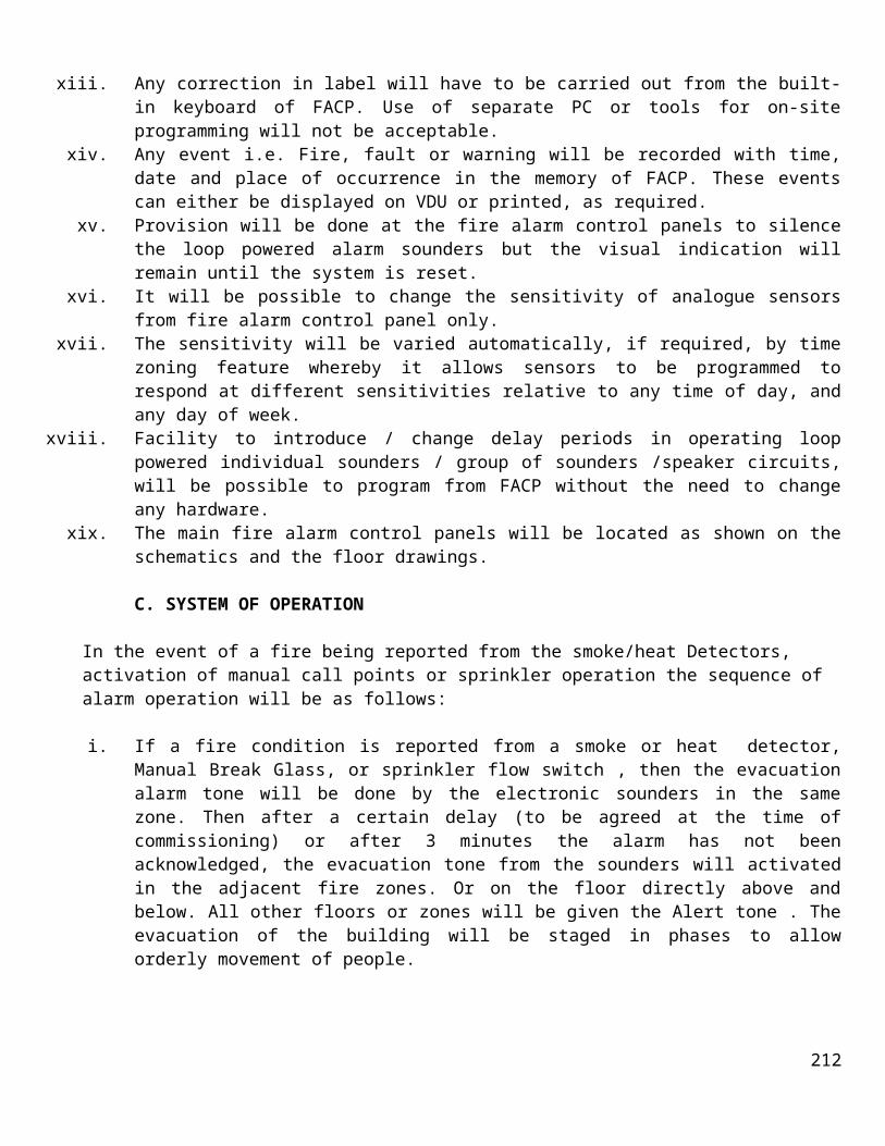
ATCOMg) IP DECT interoperability: SNOM
AscomPolycom KIRKCobs
h) IP Software phone interoperability: X-Lite Version 3.0
2.15.4 Sub-station IP with 1 Button
a) Protection: Vandal resistant design 2 mm stainless steel front plate Tamper proof fastening screws, buttons and loudspeaker grills
b) Call button: 16 mmØ stainless steelc) Power: Power over Ethernet, IEEE 802.3 a-f
Local power (19-27 VDC)Max. 8W
d) Connectors: 2xRJ45 (Ethernet) 10/100 Mbit/sec.Pluggable screw terminals.
e) IP protocols: IP v4 - TCP - UDP - HTTP - RTP - RTCP -DHCP - DiffServ - TOS – STENTOFON CCoIP
f) Audio technology: Wideband 200 Hz - 7 kHz (G.722)Telephony 3.4kHz (G.711)Acoustic echo canperimeterationOpen duplexAdaptive jitter filter1.5Watt audio outputExternal audio output (0 dB, 600 ohm)
g) Installation: Remote automatic software upgradeCentralized provisioningDHCP and static IPIntegrated web server
h) Operation: Network supervisionVoIP statisticsCentralized monitoring, Tone test
i) Advanced features: Dual port Ethernet switch for connecting CCTV cameras andother IP stations.Programmable inputs, (closing contact) or monitoring door status and alarms if not used for call buttons.Programmable relay output for door control, switch on beacon, etc. (1A at 24V DC)
2.15.5 Rainshield Stainless steel
a) Construction: Stainless Steelb) Installation: Gooseneck / Surface Mount
2.15.6 Stainless Steel Intercom Gooseneck with Baseplate
212

a) Construction: Stainless Steel gooseneck for superior durability in coastal areasUniversal mounting plate
b) Dimensions: 51mm diameter x 1355mm total height x 280mm overhang
2.16 PERIMETER INTRUSION DETECTION SYSTEM
Kinematics Detection System
2.17.1 D221 - 2 Wire Insens Sensor.
a) Power: 24V, 4mA supplied via 2-Wire interfaceb) Surge Protection: Gas Arrestor, Inductor, Tranzorb. Class 3.c) Communication Protocol: 2W proprietary @ 38Kbpsd) Data Conversion: Data onto Powere) Operating Temperature: -20°C to 70°C
2.17.2 L2W.
a) Surge Protection: Gas Arrestor, Inductor, Tranzorb, Class 3.b) Communication Interface 1: Moduteq 2W proprietary @ 38Kbpsc) Communication Interface 2: RS485 @ 1.84 Mbps Max. amount of Devices: - 200d) Power (input): Input 24V, 24W Max(depending on connected devices)
supplied by Linkbuse) Power (output): Input 24V, 24W Max on 2W interfacef) Max cable length: 500 meter (OEM Approved Maximum).g) Max 2W Devices: 32.h) Over Current protection: Yesi) Operating Temperature: -20°C to +70°C j) Ingress Protection: IP65 rated enclosure if mounted outdoors
2.17.3 LC - Linkbus ↔ Ethernet Bridge.
a) Data Conversion: Linkbus ↔ TCP/IP over 10/100 Ethernet.b) Module Power Requirements: 100mA Max, 24VDCc) Communication Protocol: RS485d) Communication Speed: 1.84 Mbpse) Operating Temperature: -20°C to +70°C f) IP Rating: 30
2.17.4 LCX - Controller.
a) Power Requirements: 24Vb) Communication Protocol: RS485c) Communication Speed: 1.84 Mbpsd) Operating Temperature: -20°C to +70°C e) IP Rating: 30
2.17.5 LOM - Linkbus ↔ Multimode Fibre Bridge.
213

a) Data Conversion: Linkbus ↔ Multimode Fiber Communicationb) Power Requirements: 24Vc) Communication Protocol: RS485d) Communication Speed: 1.84 Mbpse) Max. amount of Devices: 200f) Operating Temperature: -20°C to +70°C g) IP Rating: 30
2.17.6 PSU220/24 - Linkbus Power Supply Unit.
a) Input Voltage: 85-264 VACb) Input Frequency: 47-63 Hzc) Input Current: 0.85 A Max. @ 230 VACd) No Load Input Power: 0.48 W Max.e) Output Voltage: 24 VDCf) Max. Output Current: 2.5 A (Nominal), 3.1 A (Peak)g) Line Regulation: ±0.5% Max.h) Load Regulation: ±1% Max.i) Over Voltage Protection: Trip @ 29 VDCj) Short Circuit Protection: Trip & Restart.k) Operating Temperature: -10°C to +70°C l) Cooling: Natural convection
2.17.7 LPI - Linkbus PSU Interface
a) Input Voltage (From PSU220/24: 24 VDCb) Max. Input Current: 2.5 A (Nominal), 3.1 A (Peak)c) Surge Protection: Class 3 - Inductor, Gas Arrestor, Tranzorbd) Output Voltage: 24 VDCe) Max. Output Current: 2.5 A (Nominal), 3.1 A f) Operating Temperature: -10°C to +70°C
Advanced Acoustic Detection System
2.17.8 Environmental operating range
The system shall operate within specifications under the following environmental conditions:
Temperatures between -40°C to +70°C Relative humidity between 0 and 95%, non-condensing
2.17.9 Powering options
The processor shall operate at 12 VDC, and shall accept input power from two types of supplies, a DC power/float charger or a centrally located low voltage DC power source.
A. DC power/float charger
214

A DC power/float charger shall be provided to supply 13.5 VDC to the processor and to charge a back-up battery. The float charger shall be available in 230VAC, 50 Hz. The float charger shall be capable of being plugged into a standard AC power source.
B. Back-up battery
The processor shall include a rechargeable 12 VDC, 0.8 amp hour, gel-cell, back-up battery. The back-up battery shall be capable of being charged by the DC power/float charger.
C. Centrally located low voltage DC power source
For multiple processors deployed around a large perimeter, or a single processor that requires a long power feed cable, a centrally located DC power source shall be a viable power supply option. The processor shall be capable of receiving DC power from 18 VDC, 50 mA (minimum) to 56 VDC, 15 mA (maximum) sources. A 24 VDC power supply (85 to 245 VAC, 50/60 Hz @ 1.25 A) shall be available as an option.
2.18 SURGE PROTECTION DEVICES (SPDs)
2.18.1 Class 1 high energy Metal Oxide Varistor (MOV) - (Power Protection: Lightning Protection:)
For protection against partial direct and indirect lightning strikes.
a) Certified under; tested to: UL 1449, (UL file E213469); IEC - 61643-1b) Class (IEC): I, IIc) Max permitted operating voltage: 275/350Vd) Nominal discharge current (8/20) In: 70kAe) Max discharge current (8/20) lmax: 150kAf) Max discharge current (10/350) limp: 25kAg) Protection level Up-at limp (10/350): 1.2kVh) Response time tA: <25 nsi) Back-up fuse (if mains is > 250A): 250Aglj) Short - circuit capability to: 25kA / 50Hzk) Temperature range: -40°C to +80°Cl) Location of use: Main distribution boards (First incoming point).
2.18.2 Class 2 Silicon Avalanche Diode (SAD) - (Power Protection: Critical Electronic)
For protection of sensitive digital equipment.
a) Certified under; tested to: IEC 61643-1b) Class (IEC): Class IIc) Max permitted operating voltage: 250 VRMSd) Nominal discharge current (8/20) In: 15kAe) Max discharge current (8/20) lmax: 20kAf) Protection Level UP: 480Vg) Response time tA: <5 nsh) Temperature range: -40°C to +80°Ci) Degree of Protection: IP 20j) Location of use: Sub-distribution boards or as close as possible to a
215

protected device (Internal Distribution Point)
2.19 CABLING)
2.19.1 Category 6 or Cat 6 cable
a) Speed: 10/100/1000MbE, 10GbE (Shorter Distances or Cat6a Required for 10GbE)
b) Frequency: Up to 550 MHzc) Performance: SNR higherd) Maximum Cable Length: 100 meters; 10GbE over shorter distances.
2.19.2 FIRE RESISTANT CABLE – PH30 (STANDARD)
a) Conductor: 1.5mm² High conductivity annealed stranded plain bunched copperwire or solid plain copper wire.
b) Insulation: High temperature fire resistant core wrapping with halogen free compound
c) Insulation Colour: DIN VDE colour code d) Make-up: Multi-cores and Multi-pairs e) Screening: Overall aluminium foil screen f) Sheath: Non-toxic halogen free low smoke flame retardant compound g) Sheath Colour: Red as a standard colour (alternative colours on request) h) Required Standard: Fire resistance meeting the test requirements of BS EN 50200 for a 30
minute survival time at 840°C, which complies to SANS 10139 standard.
i) Voltage: 300/500V j) Performance: PH30 burns for 30 minutes at 840°C
2.19.3 Fibre Optic Cables
A. Low Count Duct Optic Fibre Cable
i. The cables shall be specifically designed for employment of low fibre counts in the duct environment.
ii. These cables shall be suitable for duct applications, both long haul and for LAN backbone in the industrial environment.
iii. A non-metallic construction shall ensure lightning immunity.iv. The cables shall be furnished with high modulus glass strength members, applied contra-helically, to
withstand high installation tensions, and to eliminate torsional stresses.v. The tough water resistant outer sheath as well as the gel filled loose tube shall ensure the cables’
suitability for the duct environment.vi. The cables shall be available in either flame retardant PVC or Low Smoke Zero Halogen (LSZH),
fire retardant, non-toxic sheaths to comply with the strictest building regulations.vii. This cable shall be small and lightweight, and tolerate a small bend radius for ease of installation.
The small cable size also makes it possible to efficiently utilise duct space.
B. Low Loss Single Mode Optic Fibre
216

i. The cables shall be ideally suited for industrial applications, specifically designed for short haul duct installations.
ii. A non-metallic construction shall ensure lightning immunity.iii. These cables shall be robust and provide experimeterent protection from crushing forces.iv. They shall provide sustained reliability over a wide temperature range. v. They shall remain relatively stress free while the cable contracts and expands with temperature
differences.vi. The tough water-resistant sheath and gel filled tubes ensure its suitability for the duct environment.
vii. In addition, the cable shall be available with a Low Smoke Zero Halogen (LSZH) sheath to comply with the strictest building regulations.
2.20 POWER SUPLIES (Industrial DIN Rail Mounted Power Supplies)
2.20.1 Primary switched power supply, 1-phase, output current: 5 A
A. Input data
i. Input nominal voltage range: 220 V ACii. AC frequency: 50 Hz
iii. Current consumption: 0.9 A (230 V AC)iv. Inrush current limitation: < 15 Av. Power failure bypass: > 110 ms (230 V AC)
vi. Typical response time: < 1 svii. Protective circuitry: Transient surge protection Varistor
viii. Input fuse, integrated: 3.15 A (slow-blow, internal)
B. Output data
i. Nominal output voltage: 24 V DC ±1%ii. Setting range of the output voltage: 22.5 V DC to 29.5 V DC
iii. Output current: 5 A (-25°C to 55°C)iv. Current limitation: Approx. 10 A (for short circuit)v. Max. capacitive load: Unlimited
vi. Surge protection against internal surge voltages: Yes, < 35 V DCvii. Degree of protection: IP20
viii. Ambient temperature (operation): -25 °C to 70 °C (> 55° C derating)ix. Max. permissible relative humidity (operation): 95 % (at 25°C, no condensation)
2.20.2 48 VDC power supplies
a) Operating Temperature: -10 to 60°Cb) Relative Humidity: 20 to 90% RHc) Input power: 75 Wd) Input nominal voltage range: 220 V ACe) AC frequency: 50 Hzf) Output current: 1.6 Ag) Output voltage: 48 V DCh) Output power: 76.8 W
217

2.21 HIGH SECURITY FENCE SYSTEM
This shall be a mesh type fence It shall be supplied with two types of galvanizing: For costal and for inland There shall be guarantees given for coastal and for inland
2.21.1 Double Line Mesh Panel Fence System
The fence system shall comprise of the following components:
Fence PostsCover PlatesTop RailsBottom RailsMesh PanelsAccessories (Bolts, shear off nuts, washers, neoprene strips, etc)
A. Top rails
The Top rail shall comply with the following specifications:
i. 2.996m x 40 x 40 x 3mm angle iron, predrilled holes for fixing rails to posts & for fixing top section of mesh to rail.
ii. Top rail to be fitted with 32mm x 2mm serrated comb, fillet welded 10mm at every 100mm centres, including bolts, shear nuts & washers M8 x 30mm stainless steel cup square bolts to fixed rails to posts
iii. M8 x 40mm stainless steel cup square bolts to fixed top section of mesh to railsiv. Coating:
Hot-dipped galvanised in accordance with ISO 1461Minimum Thickness of the Galvanizing: 70μm.
B. Bottom rails
The Bottom rail shall comply with the following specifications:
i. 2.996m x 40 x 40 x 3mm angle iron, predrilled holes for fixing rails to posts & for fixing top section of mesh to rail, including bolts, shear nuts & washers
ii. M8 x 30mm stainless steel cup square bolts to fixed rails to postsiii. M8 x 40mm stainless steel cup square bolts to fixed bottom section of mesh to railsiv. Coating:
Hot-dipped galvanised in accordance with ISO 1461Minimum Thickness of the Galvanizing: 70μm.
C. Double Line Mesh Panels
The Double Line Welded Mesh Panels shall comply with the following specifications:
i. The mesh panels shall be manufactured from high tensile Galfan Class A coated wire.
218

ii. The wire coating should be in accordance with SANS 10244-2:2003 specification (min. 275g/m2).iii. Inside apertures: 76.2mm x 12.7mmiv. Wire diameter: 3.96mm Zincalu v. Width of panel: 3048mm
vi. Height of panel: 2385mmvii. Tensile Strength of wire: 650 – 900 N/mm2
viii. Weld strength: (60 – 80) %ix. Coating:
Hot-dipped galvanised in accordance with ISO 1461Minimum Thickness of the Galvanizing: 70μm.
D. Cover Plates
i. Coating:Hot-dipped galvanised in accordance with ISO 1461Minimum Thickness of the Galvanizing: 70μm.
E. Angle Iron Posts
i. 70 x 70 x 6 mm.ii. Hot dipped galvanised in accordance with ISO-1461 and pre-drilled with holes for fixing panels,
including (70 x 6 mm) cover plate section
F. Fixing Accessories
Accessories (Bolts, shear off nuts, washers, neoprene strips, security screws, rivnuts, etc)
i. M8 x 40mm Stainless steel countersunk flush lock bolts, stainless steel fender washers ii. M8 x 25mm x 2mm & M8 stainless steel shear nuts to attach covering plate and mesh panels to
posts. iii. M8 x 30mm Stainless steel cup square bolts, stainless steel fender washers M8 x 25mm x 2mm &
M8 stainless steel shear nuts to attach bottom & top section of mesh to rails. iv. M8 x 50mm Stainless steel cup square bolts, stainless steel fender washers M8 x 25mm x 2mm &
M8 stainless steel shear nuts to attach ends of rails to postsv. A self-adhesive 40 mm x 5 mm Neoprene Strip to be placed between the Posts & Panels and between
the Panels and the Cover Plates
G. Concrete slab for outer security fence
i. A 25/19mm concrete slab must be cast in situ along the inside of the external fence. ii. The dimensions of the slab shall be as follows: 1300 (Width) x 100mm (Depth) as specified on top of
prepared ground level.iii. An expansion gap of 50mm wide must be provided at 3000mm intervals, to provide drainage and
movement. iv. Civil construction will include route preparations, and casting of the 1000mm wide concrete slab on
the outside of the fence with welded mesh steel reinforcing to a nominal thickness of 100mm and a minimum compressive strength of 20Mpa.
v. The area underneath the concrete plinth shall be cleared of all vegetation prior to casting and treated with a suitable sterilization herbicide to prevent any vegetation growth.
219

vi. The contractor shall allow and install a 250micron PVC sheet underneath the concrete slab, to prevent any vegetation growth.
H. Sliding Gates
The gate shall be manufactured from mild welded steel tubes, class III hot dip galvanized in and outside to SANS 121:2000 (minimum 275 g/m2, 2 sides combined).
i. 4m Single-leaf Motorized Sliding Gates
Track System Motorised Single LeafGate Width 4000mmGate Height (Frame) 2940mmColour Anthracite RAL 7021Frame 100mm x 50mm x 2.5mmVertical Infill frame 100mm x 50mm x 2.5mmHorizontal Infill frame 76mm x 50mm x 2.5mmGuide Posts 100m x 100mm x 6mm End Posts 100m x 100mm x 6mm Sliding Gate Rack 30mm x 10mmSliding Gate track/Ground Rail 16mm Galvanized Round BarSliding Gate Wheels 100mm Solid Steel “U” Profile Wheel with sealed bearingsSliding Guide Rollers Nylon Guide RollersBearings 6204 ZZ
ii. 5m Single-leaf Motorized Sliding Gates
Track System Motorised Single LeafGate Width 5000mmGate Height (Frame) 2940mmColour Anthracite RAL 7021Frame 100mm x 50mm x 2.5mmVertical Infill frame 100mm x 50mm x 2.5mmHorizontal Infill frame 76mm x 50mm x 2.5mmGuide Posts 100m x 100mm x 6mm End Posts 100m x 100mm x 6mm Sliding Gate Rack 30mm x 10mmSliding Gate track/Ground Rail 16mm Galvanized Round BarSliding Gate Wheels 100mm Solid Steel “U” Profile Wheel with sealed bearingsSliding Guide Rollers Nylon Guide RollersBearings 6204 ZZ
iii. Sliding Gate Sweeper
To be installed on the gate in order to sweep the track every time the gate is opened or closed. The sliding gate sweeper shall keep the track or rail clean and free of sand, dust, stones, mud and all other debris that prevent the gate from opening and closing properly.
220

iv. GATE MOTOR
Input voltage 220V ± 10% , 50HzMotor voltage 24V DCMotor power supply Battery driven (standard capacity – 2 x 7AH)Battery charger 2A @27.5VCurrent consumption (mains) 170mACurrent consumption (motor at rated load) 4AOperator push force – starting 40kgfOperator push force – rated 30kgfGate mass – maximum 1000kgGate length – maximum 100mGate speed – varies with load 22 – 26m/minMaximum number of operations per day 750Manual override Lockable lever with key releaseOperations in standby with 2 x 7AH battery:Half dayFull day
8769
Collision sensing ElectronicOperating temperature range -15oC to +50oCOnboard receiver type Rolling code multi channelReceiver code storage capacity 500 transmitter buttonsReceiver signal frequency 433MHzRemote gate status indicator
v. INFRA-RED BEAMS
Power supply 12V - 24V DC/AC Power consumption:TransmitterReceiver
21mA @ 12V 43mA @ 12V
Maximum distance 40mContact output rating 5A@ 220V AC (non conductive)Operating temperature -15oC to 55oCOperating humidity 0-90% non condensingIP rating IP54
2.21.2 Prestressed Hollow-core Fence System
Security wall system
A. Prestressed slab
i. Depth: 120mmii. Width: 1200mm
221

iii. Length: 3000mmiv. Min. concrete strength at 28 days: 50mPav. Fire rating: 1 hour
2.22 PERIMETER LIGHTING SYSTEM
2.22.1 High Performance Security Light Luminaire
a) x 26W compact fluorescentb) INGRESS PROTECTION Lamp compartment: IP66 Gear compartment: IP66
222