tennessee technological university - national energy …€¦ · · 2013-07-10tennessee...
TRANSCRIPT
An Alternative Low-Cost Process for Deposition of MCrAlY Bond Coats for Advanced Syngas/Hydrogen Turbine Applications
Y. Zhang and B. L. Bates
Tennessee Technological University
2011 University Turbine Systems Research Workshop
Columbus, OH
October 25-27, 2011

• One of materials needs for advancement of IGCC power
plants is to develop low-cost and effective manufacturing
processes for application of new TBC/bond coat
architectures with enhanced performance and durability
in syngas/hydrogen environments.
Coating Development Need for IGCC (Integrated Gasification Combined Cycle)
2
(http://www.aecengineering.com)
(http://www.ge-7fa.com)
(Padture, et al., Science, 2002)

• Depending on the bond coat choice and fabrication process
the TBC failure mechanisms can be quite different
Bond Coat Choices
• Bond coat choices
– Diffusion aluminide
– MCrAlY overlay (M = Ni, Co or a
mixture of Ni & Co)
More flexibility with regard to
composition
Lower DBTT
Coat Coat
(Padture et al., Science, 2002) 3
(Eskner, M., PhD. Thesis, 2004)

• Current fabrication processes
– Low-pressure plasma spray (LPPS)
– Air plasma spray (APS) & high-velocity oxy-fuel (HVOF)
• Limitations of thermal spray processes
– Line-of-sight, requiring complex robotic manipulation for
complete coverage
– Oxide content can be high in APS and HVOF coatings
– High porosity level in APS
• Alternative coating processes for bond coat fabrication
– Electrolytic codeposition
– Electrophoresis
– Autocatalytic electroless deposition
Processes for Bond Coat Fabrication
4

• Electrolytic codeposition (“composite electroplating”):
Fine powders dispersed in an electroplating solution
codeposit with the metal onto the cathode to form a
multiphase coating.
Why Electro-codeposited MCrAlY Coatings?
5
– Low cost (capital
investment, energy
consumption, powder
waste)
– Non-line-of-sight
– Ability of producing
homogeneous and
dense coatings
(Guglielmi, J. Electrochem. Soc., 1972)
Loosely
Adsorbed
Fully Adsorbed –or—
Embedded
Codeposited Layer

• Ni-Al based coatings with Al or Al2O3 particles
(Susan et al., Thin Solid Films, 1997; Susan & Barmak, Oxid. Met.2002; Liu &
Chen, Corros. Sci., 2007)
• The two-step process:
Extensive studies have been conducted on Ni-Al
based coatings via electrolytic codeposition
6
Step 1: Electrodeposition (Ni matrix with embedded Al
particles)
Step 2: Diffusion treatment
(Ni alloy coating containing
Ni3Al intermetallic phase)
Ni3Al Ni Matrix
Step 1 Step 2

• After heat treatment, a coating with a mixture of (Ni) + ’
(Ni3Al) was formed with significant Kirkendall porosity.
Kirkendall Porosity in the Ni-Al Coating due to
Different Intrinsic Diffusivities between Ni and Al
As-deposited Ni-Al coating After heat treatment (850ºC/10h)
• As a result of high porosity, the NiAl-based coatings showed poor
oxidation performance.
(Susan et al., Metall. Mater. Trans. A, 2001)
7
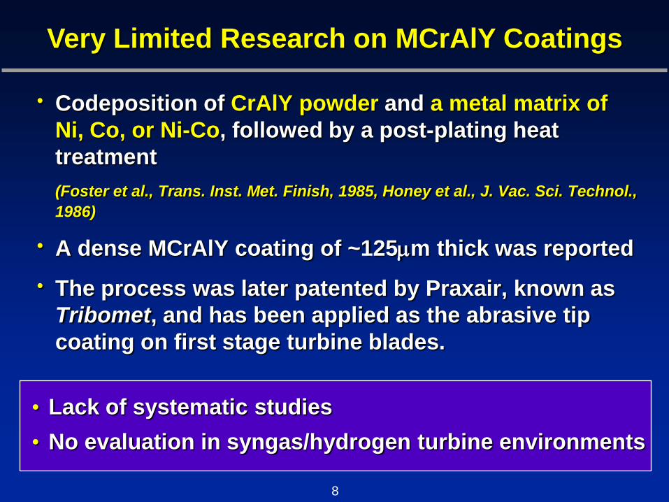
• Codeposition of CrAlY powder and a metal matrix of
Ni, Co, or Ni-Co, followed by a post-plating heat
treatment
(Foster et al., Trans. Inst. Met. Finish, 1985, Honey et al., J. Vac. Sci. Technol.,
1986)
• A dense MCrAlY coating of ~125m thick was reported
• The process was later patented by Praxair, known as
Tribomet, and has been applied as the abrasive tip
coating on first stage turbine blades.
Very Limited Research on MCrAlY Coatings
• Lack of systematic studies
• No evaluation in syngas/hydrogen turbine environments
8

• It is believed that five consecutive steps are engaged
during the electrolytic codeposition process:
1. Formation of ionic clouds on the particles
2. Convection towards the cathode
3. Diffusion through a hydrodynamic boundary layer
4. Diffusion through a concentration boundary layer and
finally
5. Adsorption at the cathode where the particles are
entrapped within the metal deposit
Electrolytic codeposition is a more complex
process than conventional electroplating
9

• Codeposition parameters
– Type of electrolyte
– Current density
– pH
– Temperature
– Agitation
– Particle composition/size/volume
– Cathode position (plating configuration)
– Post-plating heat treatment
• Lack of systematic studies, a knowledge base needs
to be established
Synergistic Effects of Codeposition Parameters
10

Electro-codeposited MCrAlY Coatings: Critical Issues
• Sulfur Impurities, Y Reservoir, & Reactive Element Co-
doping
– Traditional electrolyte used to deposit Ni/Co matrix
involves either sulfate- or sulfamate-based
solution.
ONERA (France): an electroless process using a S-
free solution (pure nickel electroless bath and
CrAlYTa powder) (Mercier et al., Surf. Coat. Technol., 2006)
– Y/S ratio in the coating
– RE co-doping
11

• Surface Roughness
– Ra of ~10 m for APS TBC top coat
• Coating Performance Assessment
– As an abrasive tip coating: in-depth evaluations
have been reported with regard to its thermal
expansion behavior.
– For syngas/hydrogen turbines: The levels of
water vapor are considerably higher than in
natural gas.
Critical Issues (Cont’d)
12

• Develop and optimize MCrAlY bond coats for
syngas/hydrogen turbine applications using the
low-cost electrolytic codeposition process
• Improve coating oxidation performance by reducing
the sulfur impurity levels and by employing reactive
element co-doping
• Evaluate the oxidation behavior of the new bond
coat in water vapor environments
• Understand the failure mechanism of the new
TBC/bond coat architecture
Project Objectives
13

CMSX-486 (a revised version of CMSX-4)
#1: Selection of Substrate Alloys More Relevant to IGCC Applications
Key Research Components
– Oxidation in water vapor
– Understanding of failure
mechanism
– Potential technology transfer
#4: Evaluation of Coating
Performance & Failure Mechanism
– Electrolyte selection for Ni-/Co-matrix deposition
– Optimization of particle composition & volume
– Control of other codeposition parameters
– Microstructural evolution during post-plating heat treatment
#2: Development & Optimization of Electro-codeposited Coatings
#3: Microstructural
Characterization & Property
Measurement
– Microstructure
– Surface roughness &
hardness measurement
14
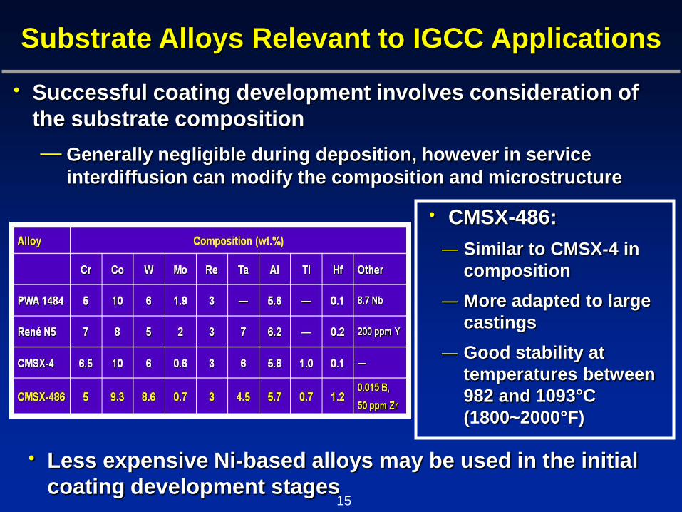
• CMSX-486:
– Similar to CMSX-4 in
composition
– More adapted to large
castings
– Good stability at
temperatures between
982 and 1093°C
(1800~2000°F)
Substrate Alloys Relevant to IGCC Applications
15
• Successful coating development involves consideration of
the substrate composition
– Generally negligible during deposition, however in service
interdiffusion can modify the composition and microstructure
• Less expensive Ni-based alloys may be used in the initial
coating development stages
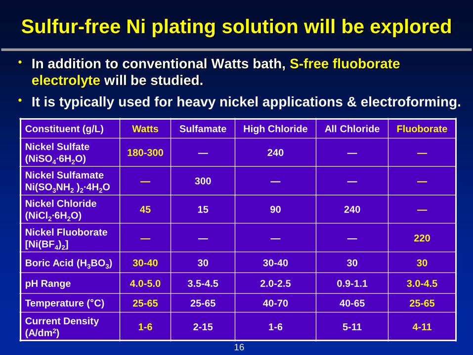
• In addition to conventional Watts bath, S-free fluoborate
electrolyte will be studied.
• It is typically used for heavy nickel applications & electroforming.
Sulfur-free Ni plating solution will be explored
Constituent (g/L) Watts Sulfamate High Chloride All Chloride Fluoborate
Nickel Sulfate
(NiSO4·6H2O) 180-300 — 240 — —
Nickel Sulfamate
Ni(SO3NH2 )2·4H2O — 300 — — —
Nickel Chloride
(NiCl2·6H2O) 45 15 90 240 —
Nickel Fluoborate
[Ni(BF4)2] — — — — 220
Boric Acid (H3BO3) 30-40 30 30-40 30 30
pH Range 4.0-5.0 3.5-4.5 2.0-2.5 0.9-1.1 3.0-4.5
Temperature (°C) 25-65 25-65 40-70 40-65 25-65
Current Density
(A/dm2) 1-6 2-15 1-6 5-11 4-11
16

• Cr/Al ratio and Y level in
electro-codeposited MCrAlY
coatings are controlled by
the CrAlY powder
composition.
• Easily adaptable to a RE
Co-doping additions
Cr/Al Ratio and Y Level in the Coating
Designation Plating Solution Particle Composition (at.%)
Coating #1 Co-Ni Cr-53Al-0.7Y
Coating #2 Co Cr-63Al-0.7Y
Coating #3 Co Cr-53Al-0.7Y
(Foster et al., US Patent 4,789,441, 1988)
17

Optimum Y Reservoir and RE Co-doping
• Even though Y (~0.5 wt.%) is commonly incorporated into
the MCrAlY coatings, a ratio of Y/S > 1 is needed to
effectively getter excess sulfur.
• The optimum Y reservoir needs to be defined to maximize
its beneficial effect on extending TBC lifetimes.
• Possible RE co-doping to further enhance oxidation
performance
(Naumenko et al., J. Mater.
Sci., 2009)
Y + Zr
(Pint et al., Mater. High Temp., 2003)
Y + Hf
18

A DoE approach will be used to investigate and optimize codeposition parameters
• 6 Factors
– Current density
– pH
– Temperature
– Particle loading
– Particle size
– Agitation
• 3 Responses
– Cathode efficiency
– Coating uniformity
– Particle incorporation
• A two-level full factorial experimental design uses all
possible factor levels in determining its model.
Response surface plot of cathode
efficiency vs. current density and
temperature (Seritan et al., Chem. Eng.
Res. Des., 2011)
Pure Ni Electroplating
19

• Where interdiffusion occurs between the CrAlY particles
and the Ni/Co matrix to achieve the final MCrAlY coating
consisting of and phases.
Evaluation of Microstructural Evolution during Post-Plating Diffusion Heat Treatment
• The post-plating heat treatment
has a significant influence on
the TGO growth rate.
• Higher temperatures under high
vacuum promote oxidation of
reactive elements and hence
increase TGO growth.
• Compatible with superalloy’s
heat treatment
20
(ASM Handbook, Vol.3, 1992)
The classsic MCrAlY coating:
18-20%Cr, 8-12%Al (wt%)
1150°C

Coating Characterization
• To provide optimum adherence for an APS TBC top coat,
a surface roughness of ~10m Ra is desirable.
• Surface roughness will be examined using profilometry
in combination with SEM cross-sectional image analysis.
• The effects of codeposition parameters and surface
treatment will be investigated.
-400
-200
0
200
400
600
800
0 2000 4000 6000 8000 10000 12000 14000 16000 18000
Ni-32.5Al-0.05Hf cast alloy, 1150°C
2 mm
21

Coating Characterization
22
25µm
• Currently we are evaluating 3D imaging software that will
provide surface and area roughness estimates.
Grit blasted surface of
R80 substrate
Surface converted to a 3D
measurable texture
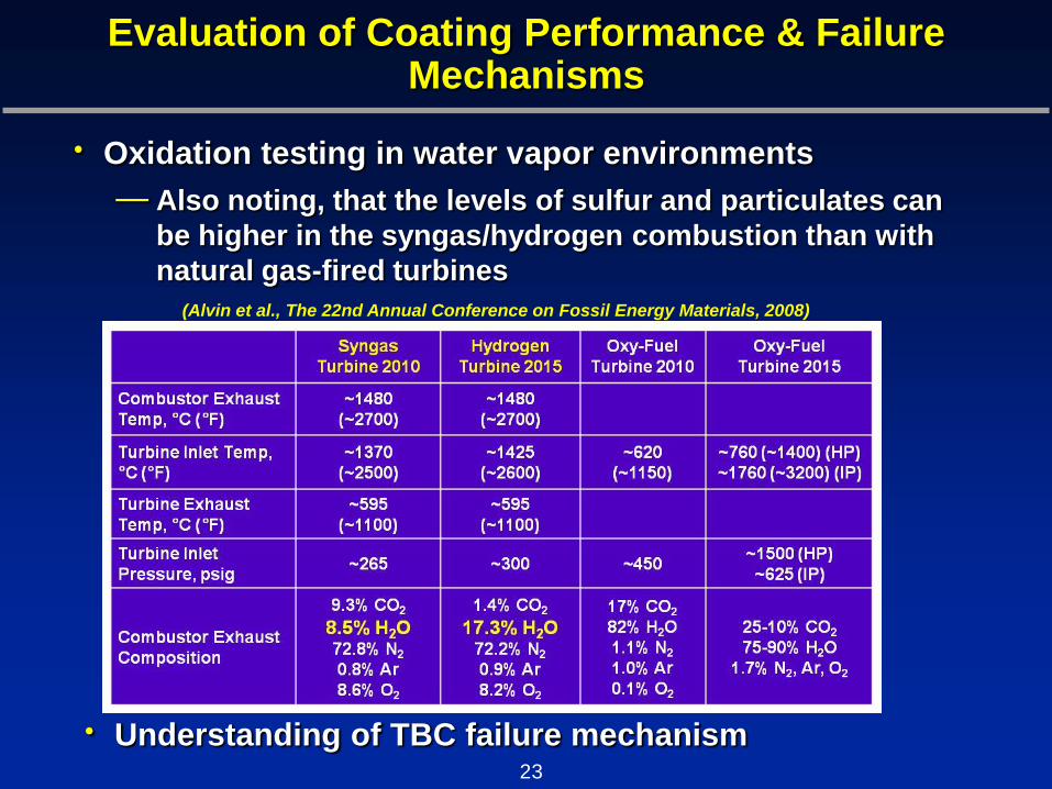
Evaluation of Coating Performance & Failure Mechanisms
(Alvin et al., The 22nd Annual Conference on Fossil Energy Materials, 2008)
• Oxidation testing in water vapor environments
– Also noting, that the levels of sulfur and particulates can
be higher in the syngas/hydrogen combustion than with
natural gas-fired turbines
23
• Understanding of TBC failure mechanism

Industrial Collaboration
• GE Global Research & GE Energy
– Dr. Voramon Dheeradhada and Dr. Warren Nelson
– Offer guidance on coating development
– The TBC lifetime will be evaluated and compared to
that of the TBCs with the state-of-the-art thermal
spray MCrAlY bond coat.
– Selected coatings with promising oxidation
performance will be further assessed by GE.
– Coatings with superior performance will be
recommended for commercial applications.
24
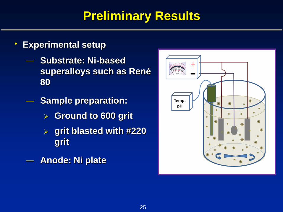
Preliminary Results
• Experimental setup
– Substrate: Ni-based
superalloys such as René
80
– Sample preparation:
Ground to 600 grit
grit blasted with #220
grit
– Anode: Ni plate
Temp.pH
25

Electroplating of Pure Ni Coating
• Watts Ni plating solution
• Current density: 3.1 A/dm2
• Temperature: 50°C
• pH: 4.0
Constituent (g/L)
Nickel Sulfate 310
Nickel Chloride 50
Boric Acid 40
0
10
20
30
40
50
0 20 40 60 80 100
Th
ick
ness
of
Ni
Lay
er
(
m)
Electroplating Time (min)
26

High-energy ball milling was used to produce Cr-Al particles of 10-15 m
• Cr-Al-based particles with ~40 at.% Al
– Cr-Al alloy made with an arc melter
– High-energy ball milling in Ar
50 m
• Particle size was reduced from ~50 m after 7 min to 10-15
m after 12 min.
7 min 12 min
27
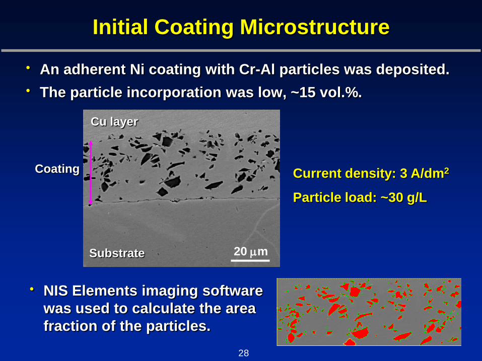
Initial Coating Microstructure
• An adherent Ni coating with Cr-Al particles was deposited.
• The particle incorporation was low, ~15 vol.%.
20 m
Cu layer
Substrate
Coating Current density: 3 A/dm2
Particle load: ~30 g/L
• NIS Elements imaging software
was used to calculate the area
fraction of the particles.
28

Improvement in Particle Incorporation
• The particle incorporation can be controlled by modifying
the current density, particle loading, stirring, etc.
20 m
Cu layer
Substrate 50 m Substrate
Revised parameters
~15% ~28%
Current density: 3 A/dm2
Particle load: ~30 g/L
29

Electro-codeposition Configuration
• Two horizontal arrangements
– The barrel unit: a semi-permeable rotating
barrel that holds the specimen and
powder
The electrolyte can diffuse through the
membrane wall, while the powder is
maintained in suspension in the barrel
Uses significantly less powder, allowing
a higher concentration if needed
– Particle incorporation is limited on
the downward-facing surface
(Honey et al., J. Vac. Sci. Technol., 1986)
(Liu et al., 2006)
30
• During initial experiments the specimen was positioned vertically
– Positioning may limit volume of
deposited particles

Summary
• The proposed research is to develop and optimize
MCrAlY bond coats for syngas/hydrogen turbine
applications using a low-cost electrolytic codeposition
process.
• The coating performance will be improved by reducing
the impurity levels in the coating and by employing
reactive element co-doping.
• The oxidation resistance of the new bond coat will be
assessed in the water vapor environments.
• The failure mechanism of the new TBC/bond coat
architecture will be studied to provide a knowledge base
for further increase of TBC lifetimes.
31

Acknowledgments
• U. S. Department of Energy - National Energy
Technology Laboratory, University Turbine
Systems Research, Award No. DE-FE0007332;
Project Manager: Dr. Patcharin Burke
• Tennessee Tech University, Center for
Manufacturing Research
32

Thank you