terminology report respect distance - etusivu - posiva1).pdf · terminology report respect distance...
TRANSCRIPT

P O S I V A O Y
FI -27160 OLKILUOTO, F INLAND
Tel +358-2-8372 31
Fax +358-2-8372 3709
Heta Lamp inen
September 2007
Work ing Repor t 2007 -69
Terminology ReportRespect Distance
The Use of the Term Respect Distance in Posiva and SKB

September 2007
Base maps: ©National Land Survey, permission 41/MYY/07
Working Reports contain information on work in progress
or pending completion.
Heta Lamp inen
Pos iva Oy
Work ing Report 2007 -69
Terminology ReportRespect Distance
The Use of the Term Respect Distance in Posiva and SKB

ABSTRACT
The term respect distance is used in some key publications of the Finnish Nuclear Waste Management Company, Posiva, and the Swedish Nuclear Waste Management Company, SKB (Svensk Kärnbrenslehantering). Posiva and SKB researchers use the same terms in their reports, and it is acknowledged that the terms used by both companies are not used in the same way, though the differences are often subtle. This report is a literature study of the term “respect distance” and the terms immediately associated to it. Vital terms related to the respect distance and issues concerning the use of scale concepts in Posiva and SKB are gathered in the end of report.
Posiva's respect distances consider the seismic, hydrological and mechanical properties of the deterministic deformation zones as important issues that constitute a risk for long-term safety. These requirements for respect distances are an interpretation of STUK's YVL 8.4 Guide. At present, Posiva’s criteria regarding respect distances follow the instructions given in the Host Rock Classification system (HRC), whereas the size of a deformation zone to which respect distances are applied vary from the regional to local major and minor. This and other criteria that are given for respect distances may, however, change in the near future as Posiva’s Rock Suitability Criteria (RSC) programme proceeds.
SKB's considerations of respect distances acknowledge that the hydraulic and mechanical aspects of a deformation zone have an effect on the respect distance. However, the seismic risk is considered to overshadow the other effects on a regional scale. The respect distance defined for a deformation zone is coupled with the size of a fracture where secondary slip could occur. In the safety assessment it is assumed that this fracture cuts a deposition hole location. In SKB the respect distance is determined for regional and local major deformation zones. The trace length of such a zone is defined as being 3 km. For deformation zones that are shorter than 3 km the margin for construction is applied. The term in question is not fixed in SKB’s use and might thus change in future. In Posiva and SKB the respect distances are applied from the boundary of the modelled deformation zone. The difference between the two approaches is that in SKB the transition zone is included within the zone width and in Posiva the influence zone is not.
Drillholes / boreholes are considered unrelated to the respect distances discussed in other forums in SKB and Posiva. For describing the distance to such holes, required from long-term safety aspect, the term restricted radius is proposed.
An important issue regarding future work with respect distances is to differentiate between “requirement”, that is, what condition is really not acceptable, and “criterion”, that is, what practically demonstrable rule should be applied to try to meet the requirement.
Keywords: respect distance, HRC-system, seismic risk, post-glacial earthquake, deformation zone, fracture zone, geological modelling, safety assessment, long-term safety, design, discriminating fracture, canister failure criterion, transition / influence zone, margin for construction, EFPC, FPC, FPI.
Terminologia-raportti. Respect Distance. Respect Distance -termin käyttö Posivassa ja SKB:llä.
TIIVISTELMÄ
Termiä respect distance (suojaetäisyys) on käytetty useissa keskeisissä Posivan ja SKB:n (Svensk Kärnbrenslehantering) raporteissa. Nämä yhtiöt vastaavat ydinjätteen loppusijoitukseen tähtäävistä tutkimuksista Suomessa (Posiva) ja Ruotsissa (SKB). Posivan ja SKB:n tutkijat käyttävät samoja termejä raportoinnissaan ja on huomattu, että yhteisesti käytettyjen termien sisältö ei ole sama, vaikka erot ovatkin usein hieno-varaisia. Tämä raportti on kirjallisuustutkimus termistä respect distance sekä siihen läheisesti liittyvistä termeistä. Oleellisimmat respect distance –käsitteeseen liittyvät termit sekä käytettyjen mittakaavojen vertailu SKB:n ja Posivan välillä on koottu raportin loppuun.
Posivan respect distance ottaa huomioon mallinnetun deformaatiovyöhykkeen seismi-set, hydrologiset ja mekaaniset ominaisuudet, mitä pidetään pitkäaikaisturvallisuuden kannalta merkittävinä riskitekijöinä. Näiden ominaisuuksien huomioiminen respect distance –asiassa perustuu STUK:in YLV 8.4 ohjeistukseen. Tällä hetkellä Posivan respect distanceen liittyvät kriteerit seuraavat sijoituskallion luokittelusysteemissä (Host Rock Classification-system, HRC) annettua ohjeistusta, jossa respect distance määrite-tään sekä alueellisille että paikallisille (suurille ja pienille) deformaatiovyöhykkeille. Tämä ja muut respect distancelle annetut kriteerit saattavat kuitenkin muuttua lähitulevaisuudessa Posivan RSC-ohjelman (Rock Suitability Criteria) edistyessä.
SKB:n respect distance ottaa huomioon deformaatiovyöhykkeen hydrauliset ja mekaaniset ominaisuudet, mutta seismisen riskin katsotaan ylittävän niiden vaikutuksen alueellisessa mittakaavassa. Deformaatiovyöhykkeelle määritetty respect distance on kytköksissä raon, jossa sekundäärinen siirrostuminen voi tapahtua, koon kanssa. Ole-tuksena turvallisuusanalyysissä on, että kyseinen rako leikkaa loppusijoitusreiän. Respect distance määritetään SKB:lla alueellisille suurille paikallisille rakenteille, joiden rajapituudeksi on määritetty 3 km. Tätä lyhyemmille deformaatiovyöhykkeille määritetään rakentamisen reuna-alue (margin for construction). Kyseinen käsite ei ole vielä vakiintunut SKB:n sisällä ja voi siten muuttua tulevaisuudessa. Respect distance määritetään sekä SKB:lla että Posivassa mallinnetun deformaatiovyöhykkeen reunalta. Erona näiden välillä on se, että SKB:lla reuna-/vaikutusvyöhyke sisältyy vyöhykkeen leveyteen, kun taas Posivassa ei.
Kaira- ja porareiät koetaan respect distance -asiaan kuulumattomiksi sekä SKB:lla että Posivassa. Kyseisten reikien ympärille jätettävälle, pitkäaikaisturvallisuuden näkö-kulmasta vaadittavalle, etäisyydelle esitetään termiä: restricted radius (rajoitettu säde).
Tulevaisuuden työssä on oleellista eritellä selvästi toisistaan ”vaatimukset” (ehdot, jotka eivät todella ole hyväksyttäviä) ja ”kriteerit” (käytännön keinot, joilla vaatimukset pyritään täyttämään), jotka liittyvät respect distance -asiaan.
Asiasanat: suojaetäisyys, HRC-systeemi, seisminen riski, post-glasiaalinen maan-järistys, deformaatiovyöhyke, rako- tai rikkonaisuusvyöhyke, geologinen mallinnus, turvallisuusanalyysi, pitkäaikaisturvallisuus, suunnittelu, diskriminoiva rako, säiliön

rikkoutumiskriteeri, reuna- / vaikutusvyöhyke, rakentamisen reuna-alue, EFPC, FPC, FPI.

1
TABLE OF CONTENTS
ABSTRACT
TIIVISTELMÄ
PREFACE....................................................................................................................... 5
1 INTRODUCTION..................................................................................................... 7
2 SKB - RESPECT DISTANCE.................................................................................. 92.1 Definition........................................................................................................... 92.2 History............................................................................................................... 9
3 COMPUTATION OF THE RESPECT DISTANCE................................................. 133.1 Parameters ..................................................................................................... 15
3.1.1 Canister failure criterion ........................................................................ 163.2 Deformation zones.......................................................................................... 17
3.2.1 Scale - the size of a deformation zone................................................. 173.2.2 Deformation zone type .......................................................................... 183.2.3 Transition zone...................................................................................... 19
3.3 Target fractures .............................................................................................. 213.3.1 Full Perimeter Criterion (FPC)............................................................... 223.3.2 Expanded Full Perimeter Criterion (EFPC) ........................................... 233.3.3 Degree-of-utilisation .............................................................................. 24
4 SKB - RESPECT DISTANCE APPLIED TO REPOSITORY DESIGN .................. 274.1 Margin for construction ................................................................................... 28
5 POSIVA - RESPECT DISTANCE.......................................................................... 315.1 Definition......................................................................................................... 315.2 History............................................................................................................. 31
6 STRUCTURAL MODELS OF OLKILUOTO AND RESPECT DISTANCE............. 356.1 Fracture zones 1987-2005.............................................................................. 35
6.1.1 R- and RH-structures ............................................................................ 366.2 Deformation zones 2006................................................................................. 38
6.2.1 Classification of deformation zones at Olkiluoto .................................. 396.2.2 Hydrogeological zones......................................................................... 41
6.3 Damage zone - influence zone ....................................................................... 426.4 Scale............................................................................................................... 43
6.4.1 Drillhole core intersections .................................................................... 446.4.2 Lineaments............................................................................................ 44
7 RESPECT DISTANCES AND HOST ROCK CLASSIFICATION .......................... 497.1 Extended classification of fracture zones in HRC........................................... 507.2 HRC system scales and respect distances .................................................... 51
7.2.1 Repository scale.................................................................................... 517.2.2 Tunnel scale.......................................................................................... 527.2.3 Canister scale ....................................................................................... 53
8 DRILLHOLES AND RESPECT DISTANCE? ........................................................ 57

2
9 DISCUSSION ........................................................................................................ 599.1 Computation and subjectivity.......................................................................... 599.2 Criteria for discrimination ................................................................................ 609.3 Deformation zones.......................................................................................... 61
9.3.1 Size issues ............................................................................................ 619.3.2 Transition zone / influence zone ........................................................... 61
9.4 Design application .......................................................................................... 629.5 Drillholes / boreholes ...................................................................................... 63
10 SUMMARY ............................................................................................................ 65
REFERENCES ............................................................................................................. 67
APPENDIX I: GLOSSARY OF TERMS RELATED TO RESPECT DISTANCE ........... 75
B ........................................................................................................................ 75Brittle deformation ................................................................................................. 75
C ........................................................................................................................ 75Canister failure criterion......................................................................................... 75Critical fracture* ..................................................................................................... 75Composite deformation zone* ............................................................................... 75Core, fault core, central core ................................................................................. 76
D ........................................................................................................................ 76Damage zone, influence zone (Posiva), transition zone (SKB)* ........................... 76Deformation zone*................................................................................................. 76Degree-of-utilisation, utilization ratio, resource ratio, exploitation ratio*................ 76Discontinuity .......................................................................................................... 77Discriminating fracture* ......................................................................................... 77Ductile deformation................................................................................................ 77
E ........................................................................................................................ 77Engineered Barrier System, EBS .......................................................................... 77Expanded Full Perimeter Criterion, EFPC* ........................................................... 77
F ........................................................................................................................ 78Fracture ................................................................................................................. 78Fracture zone ........................................................................................................ 78Fault zone.............................................................................................................. 78Fault....................................................................................................................... 78Full Perimeter Criterion, FPC* ............................................................................... 78Full Perimeter Intersection, FPI*............................................................................ 78
G ........................................................................................................................ 78Geotechnically significant fracture zone ................................................................ 78
H ........................................................................................................................ 79H-structure, RH-structure, HZ* .............................................................................. 79
I ........................................................................................................................ 79Intact rock*............................................................................................................. 79Intersection............................................................................................................ 79
J ........................................................................................................................ 79Joint ....................................................................................................................... 79
L ........................................................................................................................ 80Lineament.............................................................................................................. 80
M ........................................................................................................................ 80Moment magnitude, M, (Mw)* ............................................................................... 80

3
Margin for construction*......................................................................................... 80P ........................................................................................................................ 80
Post-Glacial Earthquake, PGE .............................................................................. 80R ........................................................................................................................ 81
R-structure* ........................................................................................................... 81Respect volume..................................................................................................... 81Rock mass............................................................................................................. 81
S ........................................................................................................................ 81Seismic influence................................................................................................... 81Seismic influence distance*................................................................................... 81Structure ................................................................................................................ 82
T ........................................................................................................................ 82Target fracture, reference target fracture* ............................................................. 82Tunnel Cross-cutting Fracture, TCF*..................................................................... 82
APPENDIX II: SCALE RELATIONS POSIVA/SKB....................................................... 83

4

5
PREFACE
The terminology report of the respect distance is a product of In Kind project, a co-operation project, between Posiva and SKB. The author wishes to thank the following persons for reviewing the report and also for giving their valuable comments and suggestions during the writing process: Raymond Munier and Rolf Christiansson of the SKB AB, Sweden, Johan Andersson of the JA Streamflow AB, Sweden, and Jussi Mattila and Liisa Wikström of Posiva Oy. Mr Christopher Cunliffe is thanked for corrections to the English of the text.

6

7
1 INTRODUCTION
The purpose of this work is to collect, compare and describe a list of terms that are linked to the concept of “respect distance”. The term respect distance is used in some key publications of the Finnish Nuclear Waste Management Company, Posiva, and the Swedish Nuclear Waste Management Company, SKB (Svensk Kärnbrenslehantering), dealing with the geological structures that affect the layout of the repository.
While Posiva and SKB researchers use same terms in their reports – a fact acknowledged by both companies – they are often used in different, though sometimes subtle, ways. Therefore, since the understanding as well as comparison between two different company policies relies heavily upon the terms and parameters used, it is important to define what is meant by each term in order to avoid misinterpretations. This concerns, of course, all possible joint projects between Posiva and SKB and is thus a vast field to cover. In this text the matter as a whole is not planned, nor meant be solved. The purpose of this text is not to resolve the problems that this causes; rather this text is more of a literature study of the term “respect distance” and the terms immediately related to it.
Originally the idea was to present the respect distance terms and their definitions as a series of tables where the similarities and contradictions of terminology could be conveniently glanced at. Unfortunately, it turned out that the respect distance issue as a whole was more complicated than optimistically expected, and that the understanding of the problematic areas would require more profound explanation.
In the text, SKBs and Posivas ideas of the respect distance are presented as independent entities that are divided into sub-chapters that focus on the different aspects of the use of the term. SKB's utilization of the term is presented in Chapters 2, 3 and 4 and Posiva's in Chapters 5, 6, 7 and 8. Chapters 2 and 5 present the use of respect distance in the history of nuclear waste management in SKB and Posiva. The rest of the respective chapters are not identical in the sense that SKB's respect distance issues are focused on the computation of the seismic affect (Munier and Hökmark 2004) for the safety analysis (Chapter 3), and in the application of the computed respect distances into proposed repository layouts (Brantberger et al. 2006, Chapter 4), whereas in Posiva no attempt at computing respect distances has been made.
In Posiva's use the respect distances have been, in general, planned values for modeled structures of some size, geotechnical quality and hydrological property (Chapter 6). The utilization of planned values of respect distances in Posiva has been taken furthest in the Host Rock Classification system, HRC (Hagros et al. (2005), Chapter 7), which is a system designed to fulfil the safety requirements presented to Posiva by STUK in YVL Guide 8.4 (STUK 2001). Furthermore, this system, including the handling of respect distances, is currently subject to revision, as further described in the Posiva R&D Programme, TKS-2006 (Posiva 2006). Finally, in Posiva the term has also been used to describe the space required to surround planned boreholes. As this application is not related to other uses of the term, it is presented separately (Chapter 8).

8
All this is concluded in the discussion section (Chapter 9), where the relevant issues concerning the contradictions in terminology are proposed with possible solutions, and summarized in the summary (Chapter 10). The terms vital to respect distance are presented in the Appendix I, and a comparison of the scale nomenclature in the Appendix II.
9
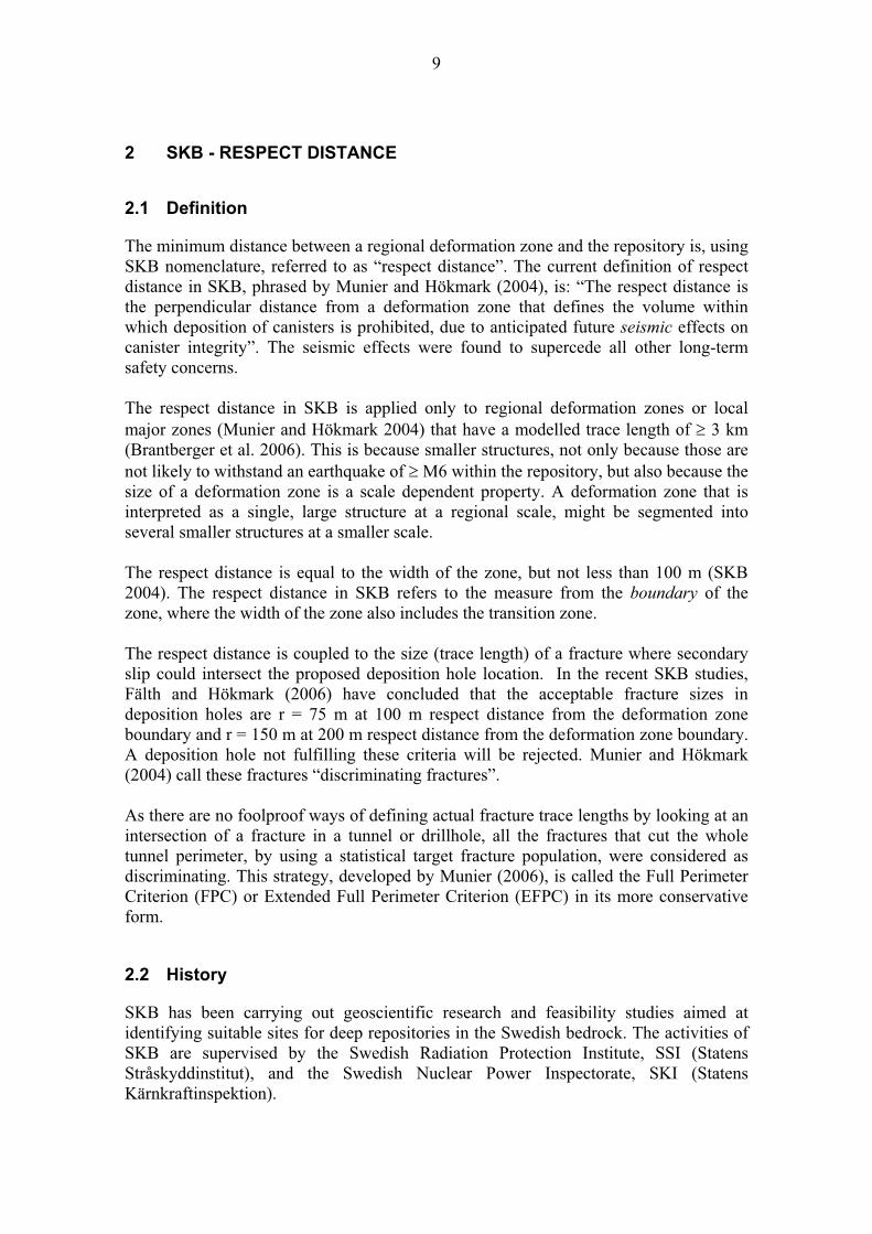
2 SKB - RESPECT DISTANCE
2.1 Definition
The minimum distance between a regional deformation zone and the repository is, using SKB nomenclature, referred to as “respect distance”. The current definition of respect distance in SKB, phrased by Munier and Hökmark (2004), is: “The respect distance is the perpendicular distance from a deformation zone that defines the volume within which deposition of canisters is prohibited, due to anticipated future seismic effects on canister integrity”. The seismic effects were found to supercede all other long-term safety concerns.
The respect distance in SKB is applied only to regional deformation zones or local major zones (Munier and Hökmark 2004) that have a modelled trace length of 3 km (Brantberger et al. 2006). This is because smaller structures, not only because those are not likely to withstand an earthquake of M6 within the repository, but also because the size of a deformation zone is a scale dependent property. A deformation zone that is interpreted as a single, large structure at a regional scale, might be segmented into several smaller structures at a smaller scale.
The respect distance is equal to the width of the zone, but not less than 100 m (SKB 2004). The respect distance in SKB refers to the measure from the boundary of the zone, where the width of the zone also includes the transition zone.
The respect distance is coupled to the size (trace length) of a fracture where secondary slip could intersect the proposed deposition hole location. In the recent SKB studies, Fälth and Hökmark (2006) have concluded that the acceptable fracture sizes in deposition holes are r = 75 m at 100 m respect distance from the deformation zone boundary and r = 150 m at 200 m respect distance from the deformation zone boundary. A deposition hole not fulfilling these criteria will be rejected. Munier and Hökmark (2004) call these fractures “discriminating fractures”.
As there are no foolproof ways of defining actual fracture trace lengths by looking at an intersection of a fracture in a tunnel or drillhole, all the fractures that cut the whole tunnel perimeter, by using a statistical target fracture population, were considered as discriminating. This strategy, developed by Munier (2006), is called the Full Perimeter Criterion (FPC) or Extended Full Perimeter Criterion (EFPC) in its more conservative form.
2.2 History
SKB has been carrying out geoscientific research and feasibility studies aimed at identifying suitable sites for deep repositories in the Swedish bedrock. The activities of SKB are supervised by the Swedish Radiation Protection Institute, SSI (Statens Stråskyddinstitut), and the Swedish Nuclear Power Inspectorate, SKI (Statens Kärnkraftinspektion).

10
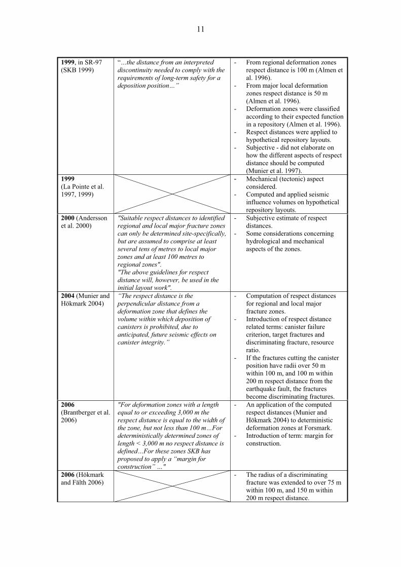
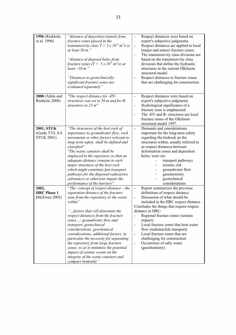
The development of the use of respect distances in the process of time in SKB is presented in Table 2-1, where the original quotation of the respect distance from a given report is presented and the main points listed.
The respect distance was originally intended to eventually include many aspects of potential importance including: thermal, hydraulic and seismic influence, with the broader definition also including the geometric uncertainty of deformation zones (Munier et al. 1997). Later the geometric uncertainty of deformation zones was concluded to be unrelated to respect distance, though it is stated that the uncertainty in the position of a deformation zone will be reflected in an uncertainty of the position of the respect volume (Munier et al. 2003).
Munier and Hökmark (2004) conclude that unless ongoing research demonstrates otherwise, the seismic influence on canister integrity overshadows the mechanical, thermal and hydraulic aspects discussed above at the regional scale. In other words, the respect distance in SKB is calculated to avoid mechanical damage of the canister if significant (post-glacial) earthquakes occur near or within the repository.
At present, the evolutionary aspect is left out of respect distance considerations. In SKB radionuclide migration is indeed still an important issue, but the application of respect distances is not considered as an appropriate means of constraining it (SKB 2006).
In order to avoid misinterpretations, another term, “functional distance”, has been proposed to express the transport resistance of > 104years/m, along the path from a canister to the biosphere via a hydraulically active deformation zone. According to Munier and Hökmark (2004), the functional distance could be a component of the total respect distance.
Table 2-1. Evolution of the respect distance in SKB.
Year /report Original quote Respect distance
1983, KBS-3 “The repository will be designed so that deposition holes will be located at a
distance of at least 100 m from the
nearest known zones with appreciably elevated water flows or where the rock
is so crushed and weakened that the possibility of rock movements cannot be
excluded…”
- Respect distance based on the hydraulic properties of the deformation zones.
- Respect distance to zones with appreciably elevated permeability was set to 100 m (KBS 1983a, b, c, d, e).
- Respect distance to zones with moderately elevated permeability was set to 25 m (KBS 1983a, b, c, d, e).
- Mechanical stability from the engineering point of view.
- No coupling to earthquakes. SKB 91/ 1992 “…An exclusion zone of 100 m to major
steeply-dipping fracture zones…reference case…”
- Similar approach to respect distance as in KBS-3 (SKB 1992).
- Respect distance based on the hydraulic properties of the zones (Munier and Hökmark 2004).
11
1999, in SR-97 (SKB 1999)
“…the distance from an interpreted discontinuity needed to comply with the
requirements of long-term safety for a deposition position…”
- From regional deformation zones respect distance is 100 m (Almen et al. 1996).
- From major local deformation zones respect distance is 50 m (Almen et al. 1996).
- Deformation zones were classified according to their expected function in a repository (Almen et al. 1996).
- Respect distances were applied to hypothetical repository layouts.
- Subjective - did not elaborate on how the different aspects of respect distance should be computed (Munier et al. 1997).
1999
(La Pointe et al. 1997, 1999)
- Mechanical (tectonic) aspect considered.
- Computed and applied seismic influence volumes on hypothetical repository layouts.
2000 (Andersson et al. 2000)
"Suitable respect distances to identified regional and local major fracture zones
can only be determined site-specifically,
but are assumed to comprise at least several tens of metres to local major
zones and at least 100 metres to regional zones".
"The above guidelines for respect
distance will, however, be used in the initial layout work".
- Subjective estimate of respect distances.
- Some considerations concerning hydrological and mechanical aspects of the zones.
2004 (Munier and Hökmark 2004)
“The respect distance is the
perpendicular distance from a
deformation zone that defines the volume within which deposition of
canisters is prohibited, due to
anticipated, future seismic effects on canister integrity.”
- Computation of respect distances for regional and local major fracture zones.
- Introduction of respect distance related terms: canister failure criterion, target fractures and discriminating fracture, resource ratio.
- If the fractures cutting the canister position have radii over 50 m within 100 m, and 100 m within 200 m respect distance from the earthquake fault, the fractures become discriminating fractures.
2006
(Brantberger et al. 2006)
"For deformation zones with a length
equal to or exceeding 3,000 m the respect distance is equal to the width of
the zone, but not less than 100 m…For deterministically determined zones of
length < 3,000 m no respect distance is
defined…For these zones SKB has proposed to apply a “margin for
construction” …"
- An application of the computed respect distances (Munier and Hökmark 2004) to deterministic deformation zones at Forsmark.
- Introduction of term: margin for construction.
2006 (Hökmark and Fälth 2006)
- The radius of a discriminating fracture was extended to over 75 m within 100 m, and 150 m within 200 m respect distance.

12
2006 (Munier 2006)
"There is a relationship between the respect distance and the size of
fractures that can be allowed to intersect the deposition holes. If a
fracture is too large it might, when
triggered by a nearby earthquake, host a slip exceeding the canister failure
criterion…"
- Introduction of the terms: Full Perimeter Criterion (FPC), Extended Full Perimeter Criterion (EFPC), Full Perimeter Intersection (FPI) and critical fracture.

13
3 COMPUTATION OF THE RESPECT DISTANCE
The concept of respect distance is used in SKB at the present day to describe a distance required from the deformation zone close to site or within it in order to avoid mechanical damage, induced by an earthquake, to the canister. From the seismic hazard point of view, the Baltic Shield, where both Sweden and Finland are located, is in a current state of relative stability, and the largest recorded earthquakes in the last 100 years in Sweden and Finland have M < 4,5; however, the majority of them has been considerably smaller (Catalogue of earthquakes in Northern Europe since 1375, http://www.seismo.helsinki.fi/bul_fi/index.html). Large earthquakes have however occurred in the area after the ice age due to the crustal unloading as the ice has melted. These earthquakes are called post-glacial earthquakes (PGE), and their magnitudes are estimated to reach up to M = 8, and perhaps even greater. These magnitudes are considered large enough to produce enough seismic energy to pose a potential hazard to the repository and in the simulations of the seismic influence, e.g. in Munier and Hökmark (2004) and Hökmark and Fälth (2006), the threshold magnitude is set at M = 6.
The estimates of the post-glacial earthquake magnitudes are based on the sizes of the post-glacial fault scarps recorded in Lapland (Lagerbäck 1988, Muir Wood 1993, Stanfors and Ericsson 1993). Although there are no observations of such faults in the vicinity of SKB's site investigation areas, Forsmark and Laxemar, SKB has chosen to assume conservatively that any large deformation zone close to the site is capable of hosting such an event. Such large deformation zones are referred to in SKB reports as local major deformation zones, or regional deformation zones. In Brantberger et al. (2006), the definition of policy of which a deformation zone is large enough, was drawn up to a threshold of 3km of modelled trace length.
The canisters with spent nuclear fuel are not allowed to be placed within deformation zones, as it might jeopardize their long-term mechanical stability, and thereby constitute a potential hazard to the biosphere (e.g. Andersson et al. 2000). Avoiding large deformation zones is, however, not enough as it is acknowledged that earthquakes trigger reactivation, a slip in secondary fault structures at some distances from their hypocentres due to stress redistribution (Figure 3-1) (Munier and Hökmark 2004). In these faults, the faulting focused on a single plane is considered to have the largest displacement, as the seismic energy is not dispersed but focused on a single plane (Cosgrove et al. 2006). Fault slip across a deposition hole, as presented in Figure 3-2, might damage the isolation capacity of the canister (Munier and Hökmark 2004). This secondary faulting related to post-glacial earthquakes is the focus of computing respect distances, as the respect distance, if successfully computed, should define the distance from the deformation zone where the secondary faulting can possibly occur. In the computations so far the 100 m reference target fractures has been used.
Attempts to compute the respect distances in SKB, from a deformation zone beyond which a canister can be safely emplaced due to seismic risk, have been made for SKB by La Pointe et al. (1997 and 1999), Munier and Hökmark (2004) and Hökmark and Fälth (2006). For these simulations, the fracture population derived from statistical fracture network models of the sites, Laxemar and Forsmark is used.

14
Figure 3-1. Schematic illustration of the extent of seismic influence from the earthquake
fault (deformation zone). Modified after slide in Raymond Munier's power point
presentation, which was held in "Respect Distance Meeting 11-12 May 2005".
The results of the most recent studies by Fälth and Hökmark (2006) indicate that the radius of a target fracture could be as large as 75 m within 100-200 m perpendicular (respect) distance from the deformation zone boundary of 3 km trace length. If the distance from the zone is > 200 m, the radius of the fracture could be 150 m. The fractures as large as this are anticipated to present themselves rather as minor fracture zones in the bedrock, and it is argued that for this reason they would not be easily missed (Cosgrove et al. 2006).
To analyze the effects of an event of a given magnitude Munier and Hökmark (2004) considered it to be conservative to look at the maximum fault displacement that is consistent with that magnitude. According to their review in published relationships between earthquake magnitude and displacement (e.g. Wells and Coppersmith 1994), the displacement on the primary fault does not exceed the threshold value 0.1 m for earthquakes of magnitude 5 and smaller. That is, no canisters would be damaged, even if the earthquake originated on a fault intersecting one or many deposition holes. Therefore, Munier and Hökmark (2004) conclude that analysis of smaller than magnitude 5 earthquakes in computation efforts is not meaningful. In the computations, the M6 reference magnitude was used. The magnitude and displacement relations mentioned above are also the basis for the 3 km criterion used by SKB for the deformation zones.

15
3.1 Parameters
The parameters, used for the computation of the seismic respect distances are presented briefly below in Table 3-1. For detailed description of the parameters, computation methodology and theory behind the simulations, see Munier and Hökmark 2004.
Table 3-1. Parameters that have been identified as relevant when computing respect
distances (after Munier and Hökmark 2004).
Context Parameter Considerations
Earthquake magnitude. M6 - M8
Earthquake fault geometry.
Strike, dip, position and dimensions of the rupture zone.
Deformation zones
Source mechanism. Average displacement of the rupture area, stress drop, rupture speed, mode of slip.
Orientation of the target fracture.
Dip and strike. The orientation of the target fracture is a key parameter that needs to be varied.
Position of the target fracture.
Distance from edge of rupture area, distance from the epicentre. The distance between target fracture and the rupture area is a key parameter and needs to be varied systematically.
Mechanical properties of the target fracture.
Shear strength parameters. The most conservative assumption is used in the calculations, which is frictionless fractures.
Target fractures
Size of the target fracture.
The maximum radius of fractures located in the deposition hole at 100-200 m distance from the deformation zone core boundary is 75 m. At distance > 200 m from the zone, maximum radius of the fracture is 150 m (Fälth and Hökmark 2006, Munier 2006). Fractures beyond these sizes are discriminating fractures, i.e. deposition in the hole is not allowed.
Mechanical properties of the of the host rock.
Elastic parameters and viscous damping parameters. The host rock was assumed to be linearly elastic, which is a conservative estimation.
Host rock
Host rock initial stresses. For post-glacial faulting, a relevant stress field is one with low vertical stress but high horizontal stress in the fault dip direction.
Maximal displacement that the EBS can withstand.
Canister failure criterion The amount of displacement allowed across the canister used in the computations is 0.1 m. The value is suspected to be overly conservative since the laboratory tests performed by Börgesson et al. (2004) show that EBS can withstand 0.2 m of shear without breaking the canister.
Some preliminary studies have been done in Posiva, regarding the seismic risk considerations and respect distances (La Pointe and Hermanson 2002), but as a whole, the current understanding of the topic, e.g. in HRC (Hagros et al. 2005), relies mainly to the results of SKB's work (e.g. Munier and Hökmark 2004). As Posiva has not yet executed similar computations for evaluating the seismic risk as SKB, there is no point of going into the computation details used by SKB. However, some of the parameters used in the computation relate to wider contexts discussed in relation to respect

16
distances (Table 3-1), such as deformation zones and target fractures. As such, the manner of how these contexts relate to the computed respect distances needs to be clarified. The deformation zone and target fracture related terminology is discussed later in Chapters 3.2 and 3.3, respectively. The term canister failure criterion is also described later in more detail, as it is one key parameters of the computation of the respect distances.
3.1.1 Canister failure criterion
The limiting value defining the canister failure criterion is 0.1 m of shear displacement across the canister (Figure 3-2). This is anticipated to damage the canister bentonite’s buffering ability, which might cause a leak of radioactive nuclides (Munier and Hökmark 2004).
According to Munier and Hökmark (2004), a number of numeric and analogue models and tests have been performed to assess how much mechanical damage the canister/bentonite system can withstand yet maintain its isolating capabilities (Börgesson, 1986, Takase et al. 1998, Werme and Sellin, 2001, 2003). Based on these investigations SKB has used a failure criterion of 0.1 m shear deformation across the canister in the safety report SR-97 and subsequent modelling efforts. In the test the shearing across the deposition hole was modelled to take place perpendicular to the canister axis (Munier and Hökmark 2004). For more technical details of the experiments concerning the canister failure criterion, see Börgesson et al. (2004).
Figure 3-2. Canister failure criterion. a) Sketch showing possible breaking of a canister
due to shear displacement along the fracture plane (Bäckblom and Munier 2002), b)
deformed structure after 20 cm rock displacement, c) detail cut at the shear plane
(From Figure 5-1 in Börgesson et al. 2004).
The value of 0.1 m shear displacement is believed to be overly conservative since in series of laboratory tests of the buffer material performed by Börgesson et al. (2004), the shear calculations were driven to a total of 0.2 m of shear without reaching the breaking threshold of the canister. Nevertheless, for practical purposes, to ensure compatibility between the various models, SKB still uses the criterion of 0.1 m shear displacement across the canister position (Munier and Hökmark 2004).
17
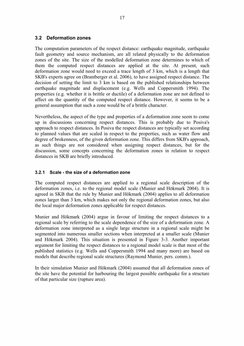
3.2 Deformation zones
The computation parameters of the respect distance: earthquake magnitude, earthquake fault geometry and source mechanism, are all related physically to the deformation zones of the site. The size of the modelled deformation zone determines to which of them the computed respect distances are applied at the site. At present, such deformation zone would need to exceed a trace length of 3 km, which is a length that SKB's experts agree on (Brantberger et al. 2006), to have assigned respect distance. The decision of setting the limit to 3 km is based on the published relationships between earthquake magnitude and displacement (e.g. Wells and Coppersmith 1994). The properties (e.g. whether it is brittle or ductile) of a deformation zone are not defined to affect on the quantity of the computed respect distance. However, it seems to be a general assumption that such a zone would be of a brittle character.
Nevertheless, the aspect of the type and properties of a deformation zone seem to come up in discussions concerning respect distances. This is probably due to Posiva's approach to respect distances. In Posiva the respect distances are typically set according to planned values that are scaled in respect to the properties, such as water flow and degree of brokenness, of the given deformation zone. This differs from SKB's approach, as such things are not considered when assigning respect distances, but for the discussion, some concepts concerning the deformation zones in relation to respect distances in SKB are briefly introduced.
3.2.1 Scale - the size of a deformation zone
The computed respect distances are applied to a regional scale description of the deformation zones, i.e. to the regional model scale (Munier and Hökmark 2004). It is agreed in SKB that the rule by Munier and Hökmark (2004) applies to all deformation zones larger than 3 km, which makes not only the regional deformation zones, but also the local major deformation zones applicable for respect distances.
Munier and Hökmark (2004) argue in favour of limiting the respect distances to a regional scale by referring to the scale dependence of the size of a deformation zone. A deformation zone interpreted as a single large structure in a regional scale might be segmented into numerous smaller sections when interpreted at a smaller scale (Munier and Hökmark 2004). This situation is presented in Figure 3-3. Another important argument for limiting the respect distances to a regional model scale is that most of the published statistics (e.g. Wells and Coppersmith 1994 and many more) are based on models that describe regional scale structures (Raymond Munier, pers. comm.).
In their simulation Munier and Hökmark (2004) assumed that all deformation zones of the site have the potential for harbouring the largest possible earthquake for a structure of that particular size (rupture area).
18
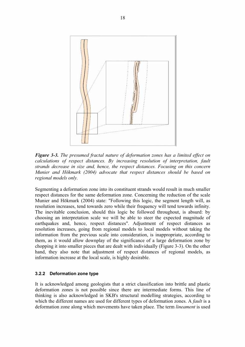
Figure 3-3. The presumed fractal nature of deformation zones has a limited effect on
calculations of respect distances. By increasing resolution of interpretation, fault strands decrease in size and, hence, the respect distances. Focusing on this concern
Munier and Hökmark (2004) advocate that respect distances should be based on
regional models only.
Segmenting a deformation zone into its constituent strands would result in much smaller respect distances for the same deformation zone. Concerning the reduction of the scale Munier and Hökmark (2004) state: "Following this logic, the segment length will, as resolution increases, tend towards zero while their frequency will tend towards infinity. The inevitable conclusion, should this logic be followed throughout, is absurd: by choosing an interpretation scale we will be able to steer the expected magnitude of earthquakes and, hence, respect distances". Adjustment of respect distances as resolution increases, going from regional models to local models without taking the information from the previous scale into consideration, is inappropriate, according to them, as it would allow downplay of the significance of a large deformation zone by chopping it into smaller pieces that are dealt with individually (Figure 3-3). On the other hand, they also note that adjustment of respect distances of regional models, as information increase at the local scale, is highly desirable.
3.2.2 Deformation zone type
It is acknowledged among geologists that a strict classification into brittle and plastic deformation zones is not possible since there are intermediate forms. This line of thinking is also acknowledged in SKB's structural modelling strategies, according to which the different names are used for different types of deformation zones. A fault is a deformation zone along which movements have taken place. The term lineament is used
19
for an unspecified, topographically and/or geophysically distinguishable linear structure in the landscape, believed to represent an intersection of a deformation zone cut by the surface. On the other hand, words such as structure, zone of weakness or discontinuity are often used to designate fracture zones in different engineering fields in SKB (Andersson et al. 2000).
In the SKB reports, deformation zone defines a 2-dimensional structure (a sub-planar structure with a small thickness relative to its lateral extent) in which deformation has been concentrated (Cosgrove et al. 2006). The term is used to encompass joints and faults (i.e. fractures), fault zones and ductile shear zones, i.e. all structures that impose a potential hazard to the integrity of the canister should they reactivate. The deformation zones can be divided into brittle, ductile or composite zones, if enough geological information is available. The term composite should be applied to deformation zones, which show evidence of both brittle and ductile deformation. In other words, composite deformation zones show evidence of brittle deformation of a zone, which is already deformed in a ductile manner (Cosgrove et al. 2006). In the history of SKB the term fracture zones has been used to designate all the different types of deformation zones where some amount of the deformation has been of a brittle character.
3.2.3 Transition zone
Deformation zones are usually described as a binary system - as a core and a volume around that is affected by it. The transition zone is that zone around the core of a (brittle) deformation zone, in which mechanical damage and associated chemical and mineralogical changes have occurred due to the process of faulting. In empirical studies by Munier and Hökmark (2004) in Äspö HRL, the transition zones recorded were asymmetric and usually larger on one side than on the other. Outside SKB use the transition zone is internationally referred to as the damage zone and sometimes as the process zone (Munier et al. 2003, Thunehed and Lindqvist, 2003, Munier and Hökmark 2004). The reason in SKB for choosing the transition zone over the internationally used damage zone was the desire to avoid confusion with the EDZ (Excavation Damage Zone) terminology (Raymond Munier pers. comm.). In Posiva's use the transition zone is typically termed damage zone (e.g. McEwen 2002), zone of influence (Paananen et al. 2006) or as in the latest reports, as influence zone (Milnes et al. 2007). The schematic diagram of the transition zone is presented in Figure 3-5.

20
Figure 3-4. Schematic diagram showing different components of a deformation zone
(Munier and Hökmark 2004). The extent of the transition zone defines the extent of the
width of the deformation zone in SKB.
In most cases the thickness of a brittle deformation zone is defined on the basis of the most deformed part, its core, which usually consists of clay filled fractures, breccia, cataclasites and other results of shear deformation. This approach is common when mapping drill cores and also in engineering geology due to obvious stability issues (Munier and Hökmark 2004). The thickness of a deformation zone in SKB is defined as including those parts of the surrounding rock that have been influenced by the presence of the zone. Defining the geometry of the deformation zone is considered essential for applying respect distances, as the respect distance is applied from the deformation zone boundary, which also includes the transition zone. In other words, the transition zone boundary is the deformation zone boundary (SKB 2006).
Previously, attempts were made to constrain the extent of the transition zone by setting some threshold values of the number of fractures/metre that the transition zone in a drillhole core would have. At present the approach is no longer considered feasible, as the fracturing is recognized as a site-specific phenomenon, and is therefore not suitable for the use as universal criteria for determining a transition zone. SKB defines the extent of transition zones for deterministic deformation zones according to experts' judgment and it is included in the total width of the zone (SKB 2006). Unless it can be defined otherwise, Munier and Hökmark (2004) have recommend a preliminary assignment of atransition zone width that amounts to 2% of the zone length, so that 1% would be on each side of the zone core. The recommendation is based on the study results of Cowie and Scholtz 1992, Knott et al. 1996, Vermilye 1996, Vermilye and Scholtz 1998, Cowie and Shipton 1998.
Respect distances have been used by designers to model deformation zones in several ways, which has much to do with the methods used for modelling in a given length of time. Sometimes those have been applied from the centre of the deformation zone (Brantberger et al. 2006) or from the deformation zone core boundary (e.g. in Munier
21
and Hökmark 2004, though it was not a directly defined rule of application). These kinds of applications are in general based on coarser structure models, e.g. lineament interpretations. As the modelling work has evolved, the most recent instructions for the applications of respect distances state that the respect distance is applied from the deformation zone boundary, where the transition zone is included within the width of the zone (SKB 2006). Therefore the rule presented in Munier and Hökmark (2004), that respect distances should at least to cover the transition zone, no longer applies as the respect distances begin from the transition zone boundary.
3.3 Target fractures
The computed respect distance is coupled with the size of the fracture, where secondary slip could occur. In the computation of the seismic impact upon the repository facility, the fractures simulated in the host rock volume, are called “target fractures". The orientation and distance between target fractures and the rupture area are varied systematically in the computation. In Munier and Hökmark (2004) the target fractures were described as perfectly planar discs or rectangles that are friction free or have small values of the friction angle. In these simulations the target fracture were also given a fixed reference length that was considered reasonably relevant to the problem. The reference radius for target fractures was 100 m. Looking at very large target fractures was not considered meaningful in the study, since such fractures, or more correctly, fracture zones, would not be allowed to intersect deposition holes for other reasons (Munier and Hökmark 2004).
The results of the recent, and similar, studies by Fälth and Hökmark (2006) implies that the acceptable fracture radii cutting the deposition hole location could be 75 m at 100-200 m respect distance from the deformation zone boundary. Beyond 200 m respect distance from the boundary the fracture radius could be 150 m (Figure 3-5). Fractures larger than this, at these distances, could slip more than the canister failure criterion allows, that is, more than 10 cm. A deposition hole not fulfilling these criteria will be rejected. Munier and Hökmark (2004), call these fractures discriminating fractures.
22
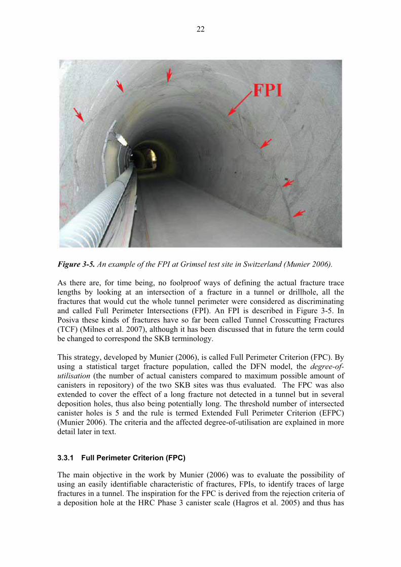
Figure 3-5. An example of the FPI at Grimsel test site in Switzerland (Munier 2006).
As there are, for time being, no foolproof ways of defining the actual fracture trace lengths by looking at an intersection of a fracture in a tunnel or drillhole, all the fractures that would cut the whole tunnel perimeter were considered as discriminating and called Full Perimeter Intersections (FPI). An FPI is described in Figure 3-5. In Posiva these kinds of fractures have so far been called Tunnel Crosscutting Fractures (TCF) (Milnes et al. 2007), although it has been discussed that in future the term could be changed to correspond the SKB terminology.
This strategy, developed by Munier (2006), is called Full Perimeter Criterion (FPC). By using a statistical target fracture population, called the DFN model, the degree-of-
utilisation (the number of actual canisters compared to maximum possible amount of canisters in repository) of the two SKB sites was thus evaluated. The FPC was also extended to cover the effect of a long fracture not detected in a tunnel but in several deposition holes, thus also being potentially long. The threshold number of intersected canister holes is 5 and the rule is termed Extended Full Perimeter Criterion (EFPC) (Munier 2006). The criteria and the affected degree-of-utilisation are explained in more detail later in text.
3.3.1 Full Perimeter Criterion (FPC)
The main objective in the work by Munier (2006) was to evaluate the possibility of using an easily identifiable characteristic of fractures, FPIs, to identify traces of large fractures in a tunnel. The inspiration for the FPC is derived from the rejection criteria of a deposition hole at the HRC Phase 3 canister scale (Hagros et al. 2005) and thus has

23
some similarities to it. The criterion assumes that FPIs are fractures large enough to host a slip that exceeds the canister failure criterion. In other words FPIs are treated as discriminating fractures if they intersect a deposition hole location (Munier 2006). The ultimate goal in the study was to evaluate whether FPC could be used as a tool for the SKB's safety assessment. A possible discriminating fracture would require a repositioning of a deposition hole, which would lead to losing the disposal space, in other words lessening the degree-of-utilisation, and as a consequence thereof raise the costs, require more volume and increase the environmental impact, among other things. In Figure 3-7 the technique of repositioning the deposition holes in the deposition tunnels due to the FPC is demonstrated.
Figure 3-7. The use of FPC. D is the minimum spacing between deposition holes due to
thermal aspects, and d is the distance of adjustment caused by the application of FPC.
3.3.2 Expanded Full Perimeter Criterion (EFPC)
Munier (2006) also noted that there is a possibility that the FPC fails to define all the possibilities of discriminating fractures existing in deposition hole locations. For instance, it is likely that large fractures exist that do not intersect the deposition tunnel, but are sufficiently close, having the potential to intersect a relatively large number of deposition holes (Figure 3-8), and so jeopardize the long-term safety of the disposal. For this the FPC was found insufficient alone to detect all potentially discriminating fractures. It needed to be complemented and Munier (2006) defined a complementary criterion, Expanded Full Perimeter Criterion (EFPC), to also address large fractures in the immediate vicinity of the tunnel, which would remain undetected by tunnel mapping. Munier (2006) proposed that the criterion would consider fractures that intersect 5 or more canister positions.

24
It was however recognized that it is possible for a discriminating fracture to intersect fewer than five deposition holes if it is located near the edge of the tunnel. For this kind of unknown effect Munier (2006) proposed to use a stricter criterion, e.g., using two intersections or more (rather than 5 or more) as the criterion, at the expense of the degree-of-utilisation. If a stricter criterion is being used, the number of canisters allowed needs to be provided. The EFPC, if not otherwise stated, will be composed of both FPC and the contribution of the expanded criterion (Munier 2006).
Figure 3-8. Illustration of how a potentially discriminating fracture can remain
undetected despite the use of the full perimeter criterion in the deposition tunnel
(Munier 2006).
The use of EFPC reduced the degree-of-utilisation further, though it was still judged to be reasonable for site evaluation in the SKB safety assessment (Munier 2006).
3.3.3 Degree-of-utilisation
The effect of earthquakes can be avoided by discriminating canister positions transected by large fractures. Since the number of canisters is constant, the disqualification of a canister position must be compensated for by the addition of new positions. The required amount of rock will therefore increase. The degree-of-utilisation is a measure on how much of the rock is available for deposition and is expressed as the ratio between the amount of canister positions that can be accepted for loading and the total amount of canister positions. The degree-of-utilisation (Munier 2006) has also been referred to as resource ratio (Munier and Hökmark 2004) and sometimes is written in a form utilisation ratio (Brantberger et al. 2006). The degree-of-utilisation can be expressed as:

25
Equation 3-1. Computing the degree-of-utilisation (Munier 2006):
Number of accepted positions 100 x Planned number of positions %
The respect distance is balanced against the degree-of-utilisation in the panels between the deformation zones and is thus strongly coupled to repository layouts and optimization. Lowering the degree-of-utilisation by, for example, applying stricter criterion has an associated cost. It is therefore considered essential not to use overly conservative assumptions. The aim is to use respect distances that yield sufficiently conservative canister hole rejection criteria to gain confidence in the scientific community and public at large, yet honour reasonable engineering and economic considerations (Munier and Hökmark 2004).

26
27
4 SKB - RESPECT DISTANCE APPLIED TO REPOSITORY DESIGN
In SKB it is acknowledged that the deformation zones and associated respect distances have a great influence on the layout (SKB 2004, Munier and Hökmark 2004). In some recent SKB reports (e.g. Brantberger et al. 2006) the computed respect distances, as defined by Munier and Hökmark (2004), have been applied to layout-planning purposes. At least for the time being, the design will consider preliminarily assessed respect distances regarding mechanical properties of the rock, which are related to potential consequences of future earthquakes in the host rock (Brantgerger et al. 2006). The hydraulic respect distances to water conducting features of the rock have not yet been considered in the design. The reason for this is that SKB’s safety assessment group evaluates the suitability of various sections of the suggested repository area, from the point of view of radionuclide transport properties later on, and thus it is excluded from the design considerations for time being (Brantberger et al. 2006). Such an evaluation is supported in SR-Can where it is stated that: “there is no reason to reconsider the respect distances currently applied in the repository layout work, but there may be reasons to avoid certain rock domains if it is shown that these generally have too high a frequency of highly transmissive fractures”(SKB 2006).
When devising repository layouts in SKB, the respect distances are applied from identified (deterministic) regional and local major deformation zones to deposition tunnels. These respect distances are composed of a distance judged to comprise a suitable minimum distance between the tunnel and deformation zone (Andersson et al. 2000). Following instructions for applying respect distances for design purposes have been given so far:
- For deformation zones with a length 3 km, the respect distance is equal to the width of the zone (including the transition zone), but not less than 100 m (SKB 2004).
- For deterministically determined zones of length < 3 km no respect distance is defined (SKB 2004). For these zones SKB has proposed to apply a “margin for construction” (Brantberger et al. 2006, SKB 2006). As respect distances, the margin for construction is also equal to the width of the modelled zone that includes the transition zone, though it has no requirement for minimum width.
The way of applying respect distances has been rather changeable in the recent history in SKB. For instance respect distances has been applied from the centre of the modelled deformation zones in some recent reports (e.g. Brantberger et al. 2006, Figure 4-1), but according to the SR-Can, the proper way of applying the respect distance should be from the boundary of the deformation zone where the transition zone is included within the zone width (SKB 2006).
The instructions for applying the margin for construction in the layout considerations are presented below, although it is not certain if the concept will be used in the next step of SKB’s design considerations. Because of this the concept margin for construction should be understood more as a working heading (the assigned distance, as well as the

28
term itself, may change as the hypothesis behind and means of constraining it evolves), rather than as a requirement (the distance based on a theory that is supported by computations) for repository design purposes, which e.g. the respect distance in SKB is.
4.1 Margin for construction
In Brantberger et al. (2006) and in SR-Can (SKB 2006) it has been stated that respect distances for deterministically determined deformation zones should be recognized when locating deposition tunnels. These deterministically determined deformation zones with a length < 3,000 m are allowed to pass deposition tunnels. However, no deposition holes are allowed within the margin for construction (Brantberger et al. 2006, SKB 2006). The margin for construction is applied from the boundary of the defined deformation zone where the transition zone is included within the zone width. The computation of the margin for construction for deformation zone is presented in Equation 4-1.
Equation 4-1. Computing margin for construction (Brantberger et al. 2006).
(Thickness of zone + variation) Margin for construction =
2+ safety margin (SM)
SM = 10 m if stability problems are expected SM = 20 m if water problems are expected SM = 5 m, default value, if stability or water problems are not expected
The margin for construction is thus to be interpreted as the distance from the centre of the zone towards the deposition holes. No deposition holes are permitted within the borders of the “margin for construction” (Brantberger et al. 2006). In Figure 4-1 the respect distances for regional fracture zones that have trace lengths of > 3000m is applied, as well as margin for construction for smaller fracture zones.
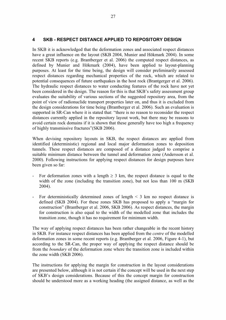
29
Figure 4-1. Deformation zones with preliminary respect distances or margin for
construction within the Forsmark site, depth 500 m (Brantberger et al. 2006).

30
31
5 POSIVA - RESPECT DISTANCE
5.1 Definition
In Posiva the term respect distance has been, and most likely will remain, as a planning value of a distance for the layout, from the boundary of a modelled (deterministic) deformation zone towards the repository premises. It is a distance that is considered to take into account the seismic, hydrological and mechanical properties of the deterministic deformation zone in the Olkiluoto bedrock, in a conservative manner so that the transportation of radionuclides from the repository to the biosphere is impossible, or takes so long time that the release of radiation is no longer significant. The application of respect distances (from the boundary of the modelled deformation zone) as well as the considerations regarding the respect distances is identical to SKB’s definition of respect distances (e.g. in SKB 2004). The differences in the definition tend to arise as we go further into solutions in practice.
The size of a deformation zone, to which the respect distance is applied according to Posiva's policy, varies from the regional to local (major and minor deformation zones), depending on the scale being discussed. The studies on the Olkiluoto site are mainly scoped at the site scale (i.e. area of 2 km x 2 km x 1 km (Paulamäki et al. 2006)), where the majority of deterministic deformation zones have modelled lengths less than 3 km. At this size scale the seismic concerns can no longer be considered to overshadow the other aspects (as it does in the scale of SKB’s site investigations), therefore the focus of the studies is often put on other long-term safety aspects, which are the hydrological and mechanical properties of the deformation zone. One goal of the site-modelling group in Posiva is to balance the weighting of the respect distance considerations by taking the seismic risk (the size of a deformation zone) more into consideration in the current modelling work. At present, the fruits of this work are not yet seen, though the work is in progress.
The term respect distance has also been used to describe a regulatory distance to the repository when drillholes are drilled, thus some clarifications, which would exclude this use of the term, will be made in the future.
5.2 History
Posiva Oy is responsible for managing the site investigation and research program and for the development of the disposal facility in Olkiluoto in Eurajoki. The place was selected after years of site investigations (the search for a suitable place began in 1983) as the potential site for the final disposal of spent nuclear fuel from the Finnish nuclear power plants in 2000 (McEwen and Äikäs 2000).
At an early stage, Finland chose to base its program on the Swedish KBS-3 concept and to run its research and development activities closely coordinated with SKB. However, the siting process diverged considerably from that of Sweden in 1983 when the Finnish government established the objectives and timetable for the siting process. The program was divided into 3 phases: Phase 1 (1983–1985) consisted of a site identification
32
survey, Phase 2 (1986–1992) encompassed preliminary site investigations at a number of sites identified during Phase 1, and a third and final phase, Phase 3 (1993–2000), which involved the detailed site characterisation of the sites studied during Phase 2. All this culminated in 2000 in a Decision in Principle, by the Government as to the future Finnish deep repository site (McEwen and Äikäs 2000).
The divergence in the siting progress between Posiva and SKB has, among other things, lead to divergence in the respect distance concept. There are quite a few reports written in Posiva, where respect distances have been defined and assigned between modelled deformation zones (fracture zones) and different parts of repository for layout and design purposes. None of these historical definitions are officially "valid" at present, but one thing is common to all of them. This is that the numerical values defining the respect distance to any structure are based on experts’ judgments. In other words the respect distances in Posiva have been bound to the structural models and their modelling principles over time, and the assigned respect distance for them has been judged to be conservative according to best knowledge available. For this reason the principle characteristics of the ways of structure modelling in Posiva are also presented. None of the reported respect distances have been based on a computation, which makes all the difference compared to the SKB's approach to the respect distance issue. In order to create an overall picture of Posivas background in the respect distance concept, the main definitions and use of the term in different reports are summarized in Table 5-1.
Table 5-1. The evolution of the respect distance in Posiva.
Year / report Original quote Respect distance
1985 (Peltonen et al. 1985)
"The repository would be located in a
rock block surrounded by fracture zones, the minimum distance between
the repository margin and the nearest
fracture zone being approximately 100 m”.
- Subjective estimate, quoted from SKB reports (KBS, 1983a, b, c, d, e).
- Safety margin from the regional fracture zones to repository.
- By fracture zones, regional fracture zones are meant.
1992 (Riekkola et al. 1992a, b)
"Minimum distance of deposition
tunnels to fracture zones bounding the
investigation site approximately 100 m, minimum distance of deposition
tunnels to fracture zones with 1st class
transmissivity approximately 50 m". "Distance of deposition holes to
fracture zones with 2nd class
transmissivity at least some tens of metres, distance of deposition holes to
fracture zones with 3rd class
transmissivity at least about 10 m". "Distance of deposition tunnels to
fracture zones with 2nd class
transmissivity and geotechnically significant fracture zones at least some
tens of metres, distance of deposition holes to fracture zones with 3rd class
transmissivity and no geotechnical
significance at least about 10 m"."Distance of deposition tunnels to all
fracture zones at least some tens of
metres."
- Respect distances were based on expert's subjective judgments.
- Hydrological significance of fracture zones is emphasized.
- The transmissivity class divisions were based on the transmissivity class divisions that define the hydraulic structures in the Olkiluoto structural models (used e.g. in Saksa 1993).
- Respect distances assigned also to fracture zones that are challenging for construction.
33
1996 (Riekkola et al. 1996)
“distance of deposition tunnels from fracture zones placed in the
transmissivity class T > 5 x 10⁻⁶ m2/s is at least 50 m.”
“distance of disposal holes from fracture zones (T < 5 x 10⁻⁶ m2/s) at
least ~10 m.”
“Distances to geotechnically-
significant fracture zones are
evaluated separately”
- Respect distances were based on expert's subjective judgments.
- Respect distances are applied to local (major and minor) fracture zones.
- The transmissivity class divisions are based on the transmissivity class divisions that define the hydraulic structures in the current Olkiluoto structural model.
- Respect distances to fracture zones that are challenging for construction.
2000 (Äikäs and Riekkola 2000)
"The respect distance for -HY-
structures was set to 50 m and for R-
structures to 25 m"
- Respect distances were based on expert's subjective judgments.
- Hydrological significance of a fracture zone is emphasized.
- The -HY and R- structures are local fracture zones of the Olkiluoto structural model 1997.
2001, STUK
(Guide YVL 8.4 STUK 2001)
“The structures of the host rock of
importance to groundwater flow, rock movements or other factors relevant to
long-term safety, shall be defined and
classified” "The waste canisters shall be
emplaced in the repository so that an
adequate distance remains to such major structures of the host rock
which might constitute fast transport
pathways for the disposed radioactive substances or otherwise impair the
performance of the barriers".
- Demands and considerations important for the long-term safety regarding the bedrock an the structures within, usually referred to as respect distances between deformation zones and deposition holes, were set:
- transport pathways - seismic risk - groundwater flow - geochemistry - geotechnical
considerations 2002,
HRC Phase 1
(McEwen 2002)
“The concept of respect distance – the
separation distance of the fracture zone from the repository or the waste
within”
“…factors that will determine the
respect distances from the fracture
zones…: groundwater flow and transport, geotechnical
considerations, geochemical considerations, additional factors, in
particular the necessity for separating
the repository from large fracture zones, so as to minimize the potential
impact of seismic events on the
integrity of the waste canisters and compact bentonite”
- Report summarizes the previous definitions of respect distance.
- Discussion of what should be included in the HRC respect distance.
Concludes the things that require respect distance in HRC: - Regional fracture zones (seismic
impact) - Local fracture zones that host water
flow (radionuclide transport) - Local fracture zones that are
challenging for construction - Occurrence of salty water
(geochemistry)
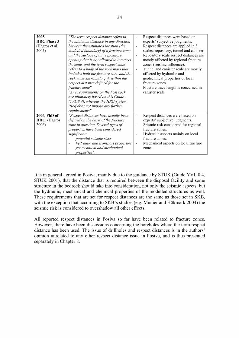
34
2005,
HRC Phase 3
(Hagros et al. 2005)
"The term respect distance refers to the minimum distance in any direction
between the estimated location (the modelled boundary) of a fracture zone
and the surface of any repository
opening that is not allowed to intersect the zone, and the term respect zone
refers to a body of the rock mass that
includes both the fracture zone and the rock mass surrounding it, within the
respect distance defined for the
fracture zone""Any requirements on the host rock
are ultimately based on this Guide
(YVL 8.4), whereas the HRC-system itself does not impose any further
requirements"
- Respect distances were based on experts’ subjective judgments.
- Respect distances are applied in 3 scales: repository, tunnel and canister.
- Repository scale respect distances are mostly affected by regional fracture zones (seismic influence).
- Tunnel and canister scale are mostly affected by hydraulic and geotechnical properties of local fracture zones.
- Fracture trace length is concerned in canister scale.
2006, PhD of
HRC, (Hagros 2006)
"Respect distances have usually been
defined on the basis of the fracture zone in question. Several types of
properties have been considered significant:
- potential seismic risks
- hydraulic and transport properties - geotechnical and mechanical
properties".
- Respect distances were based on experts’ subjective judgments.
- Seismic risk considered for regional fracture zones.
- Hydraulic aspects mainly on local fracture zones.
- Mechanical aspects on local fracture zones.
It is in general agreed in Posiva, mainly due to the guidance by STUK (Guide YVL 8.4, STUK 2001), that the distance that is required between the disposal facility and some structure in the bedrock should take into consideration, not only the seismic aspects, but the hydraulic, mechanical and chemical properties of the modelled structures as well. These requirements that are set for respect distances are the same as those set in SKB, with the exception that according to SKB’s studies (e.g. Munier and Hökmark 2004) the seismic risk is considered to overshadow all other effects.
All reported respect distances in Posiva so far have been related to fracture zones. However, there have been discussions concerning the boreholes where the term respect distance has been used. The issue of drillholes and respect distances is in the authors’ opinion unrelated to any other respect distance issue in Posiva, and is thus presented separately in Chapter 8.
35
6 STRUCTURAL MODELS OF OLKILUOTO AND RESPECT DISTANCE
In the Olkiluoto site structural models 1987-2005 the fracture zones, were modelled based on the drillhole intersections of broken rock, where the width of the zone was defined by its most deformed part, its core. The fracture zone intersections were classified into categories according to the Finnish engineering geological classification Ri -(mechanical fracturing) and Rp -(weathering) categories (Korhonen et al. 1974, Gardemeister et al. 1976). The main points of these classification methods are described briefly below. Of these drillhole intersections a 2-dimensional structure was modelled. The width of the structure was the width of the core - the existence of an influence zone, or damage zone, was sometimes acknowledged and recorded (for instance in Saksa et al. 1993), but it was not included in the total width of the structure. The respect distances were assigned in layout considerations for each fracture zone according to its mechanical and hydrological properties. Also the respect distances in HRC Phase 3 are related to this era of structure modelling, to the structural model 2003 (Vaittinen et al. 2003), which was the current model at the time, when HRC was under development.
The ideology behind the structural modelling has now changed remarkably, as the structural model no longer describes the mere brokenness of the rock (Table 6-4), but all geological characteristics of the structure that can reasonably be described (Table 6-5). The reason for this change in modelling principles was the growing need to predict and describe the Olkiluoto Site area and the ONKALO area in as detailed and accurate a way as possible, by means of geology. For this, it was decided, that all possible geological data of encountered intersections of deformation zones would be recorded. There has as yet been no statement of how respect distances should relate to these new kinds of modelled deformation zones.
The new structural model of Olkiluoto 2006 (Paulamäki et al. 2006) is divided into brittle deformation and ductile deformation models, of which the brittle deformation model corresponds the older bedrock models 1987-2005, at least in a broad sense. To notify the change in modelling by means of terminology, it was decided, that the common term used for structures, the fracture zone, would be replaced with brittle
deformation zone and its sub-definitions, presented in Table 6-5. The brokenness of the rock is, however, still recorded according to the Finnish engineering geological classification for engineering and site modelling purposes.
6.1 Fracture zones 1987-2005
The structures in the structural models of Olkiluoto, published up to 2003, (for instance in: Saksa et al. 1993, Saksa et al. 1996, Paulamäki et al. 1996, Saksa et al. 1998, Anttila et al. 1999, Äikäs et al. 1999, Vaittinen et al. 2001, Saksa et al. 2002, Vaittinen et al. 2003) and followed until 2005, were classified mainly according to their constructability and transportation properties - fracture density and hydraulic properties in the drillhole core being the most important. These models were built at a repository scale via direct observations (drillhole core intersections, trenches, outcrops), and indirectly on a larger, regional scale via indirect methodologies, such as satellite images, aerial photographs and maps. The dimensions and properties of the modelled structures
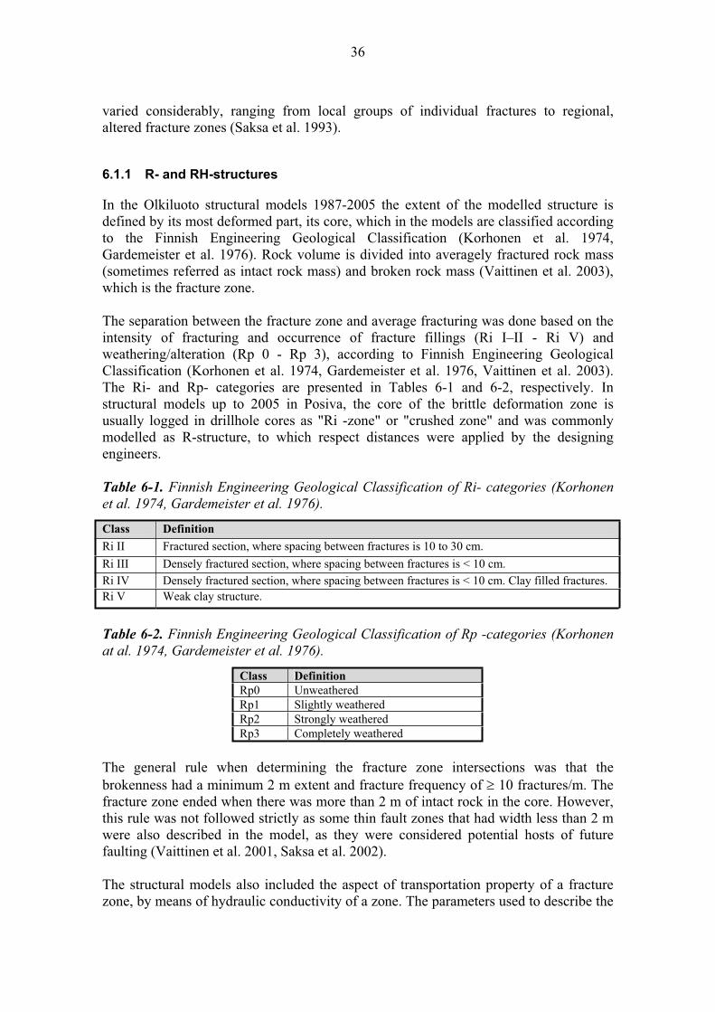
36
varied considerably, ranging from local groups of individual fractures to regional, altered fracture zones (Saksa et al. 1993).
6.1.1 R- and RH-structures
In the Olkiluoto structural models 1987-2005 the extent of the modelled structure is defined by its most deformed part, its core, which in the models are classified according to the Finnish Engineering Geological Classification (Korhonen et al. 1974, Gardemeister et al. 1976). Rock volume is divided into averagely fractured rock mass (sometimes referred as intact rock mass) and broken rock mass (Vaittinen et al. 2003), which is the fracture zone.
The separation between the fracture zone and average fracturing was done based on the intensity of fracturing and occurrence of fracture fillings (Ri I–II - Ri V) and weathering/alteration (Rp 0 - Rp 3), according to Finnish Engineering Geological Classification (Korhonen et al. 1974, Gardemeister et al. 1976, Vaittinen et al. 2003). The Ri- and Rp- categories are presented in Tables 6-1 and 6-2, respectively. In structural models up to 2005 in Posiva, the core of the brittle deformation zone is usually logged in drillhole cores as "Ri -zone" or "crushed zone" and was commonly modelled as R-structure, to which respect distances were applied by the designing engineers.
Table 6-1. Finnish Engineering Geological Classification of Ri- categories (Korhonen
et al. 1974, Gardemeister et al. 1976).
Class Definition
Ri II Fractured section, where spacing between fractures is 10 to 30 cm.
Ri III Densely fractured section, where spacing between fractures is < 10 cm.
Ri IV Densely fractured section, where spacing between fractures is < 10 cm. Clay filled fractures. Ri V Weak clay structure.
Table 6-2. Finnish Engineering Geological Classification of Rp -categories (Korhonen
at al. 1974, Gardemeister et al. 1976).
Class Definition
Rp0 Unweathered Rp1 Slightly weathered Rp2 Strongly weathered Rp3 Completely weathered
The general rule when determining the fracture zone intersections was that the brokenness had a minimum 2 m extent and fracture frequency of 10 fractures/m. The fracture zone ended when there was more than 2 m of intact rock in the core. However, this rule was not followed strictly as some thin fault zones that had width less than 2 m were also described in the model, as they were considered potential hosts of future faulting (Vaittinen et al. 2001, Saksa et al. 2002).
The structural models also included the aspect of transportation property of a fracture zone, by means of hydraulic conductivity of a zone. The parameters used to describe the
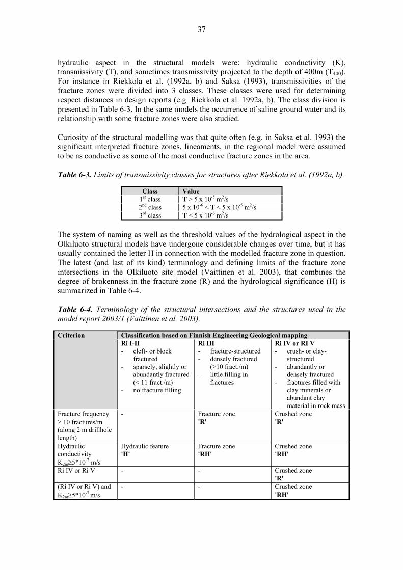
37
hydraulic aspect in the structural models were: hydraulic conductivity (K), transmissivity (T), and sometimes transmissivity projected to the depth of 400m (T400).For instance in Riekkola et al. (1992a, b) and Saksa (1993), transmissivities of the fracture zones were divided into 3 classes. These classes were used for determining respect distances in design reports (e.g. Riekkola et al. 1992a, b). The class division is presented in Table 6-3. In the same models the occurrence of saline ground water and its relationship with some fracture zones were also studied.
Curiosity of the structural modelling was that quite often (e.g. in Saksa et al. 1993) the significant interpreted fracture zones, lineaments, in the regional model were assumed to be as conductive as some of the most conductive fracture zones in the area.
Table 6-3. Limits of transmissivity classes for structures after Riekkola et al. (1992a, b).
Class Value
1st class T > 5 x 10⁻⁵ m2/s2nd class 5 x 10⁻⁶ < T < 5 x 10⁻⁵ m2/s3rd class T < 5 x 10⁻⁶ m2/s
The system of naming as well as the threshold values of the hydrological aspect in the Olkiluoto structural models have undergone considerable changes over time, but it has usually contained the letter H in connection with the modelled fracture zone in question. The latest (and last of its kind) terminology and defining limits of the fracture zone intersections in the Olkiluoto site model (Vaittinen et al. 2003), that combines the degree of brokenness in the fracture zone (R) and the hydrological significance (H) is summarized in Table 6-4.
Table 6-4. Terminology of the structural intersections and the structures used in the
model report 2003/1 (Vaittinen et al. 2003).
Classification based on Finnish Engineering Geological mapping Criterion
Ri I-II
- cleft- or block fractured
- sparsely, slightly or abundantly fractured (< 11 fract./m)
- no fracture filling
Ri III
- fracture-structured - densely fractured
(>10 fract./m) - little filling in
fractures
Ri IV or RI V
- crush- or clay-structured
- abundantly or densely fractured
- fractures filled with clay minerals or abundant clay material in rock mass
Fracture frequency 10 fractures/m
(along 2 m drillhole length)
- Fracture zone 'R'
Crushed zone 'R'
Hydraulic conductivity K2m 5*10-7 m/s
Hydraulic feature 'H'
Fracture zone 'RH'
Crushed zone 'RH'
Ri IV or Ri V - - Crushed zone 'R'
(Ri IV or Ri V) and K2m 5*10-7 m/s
- - Crushed zone 'RH'
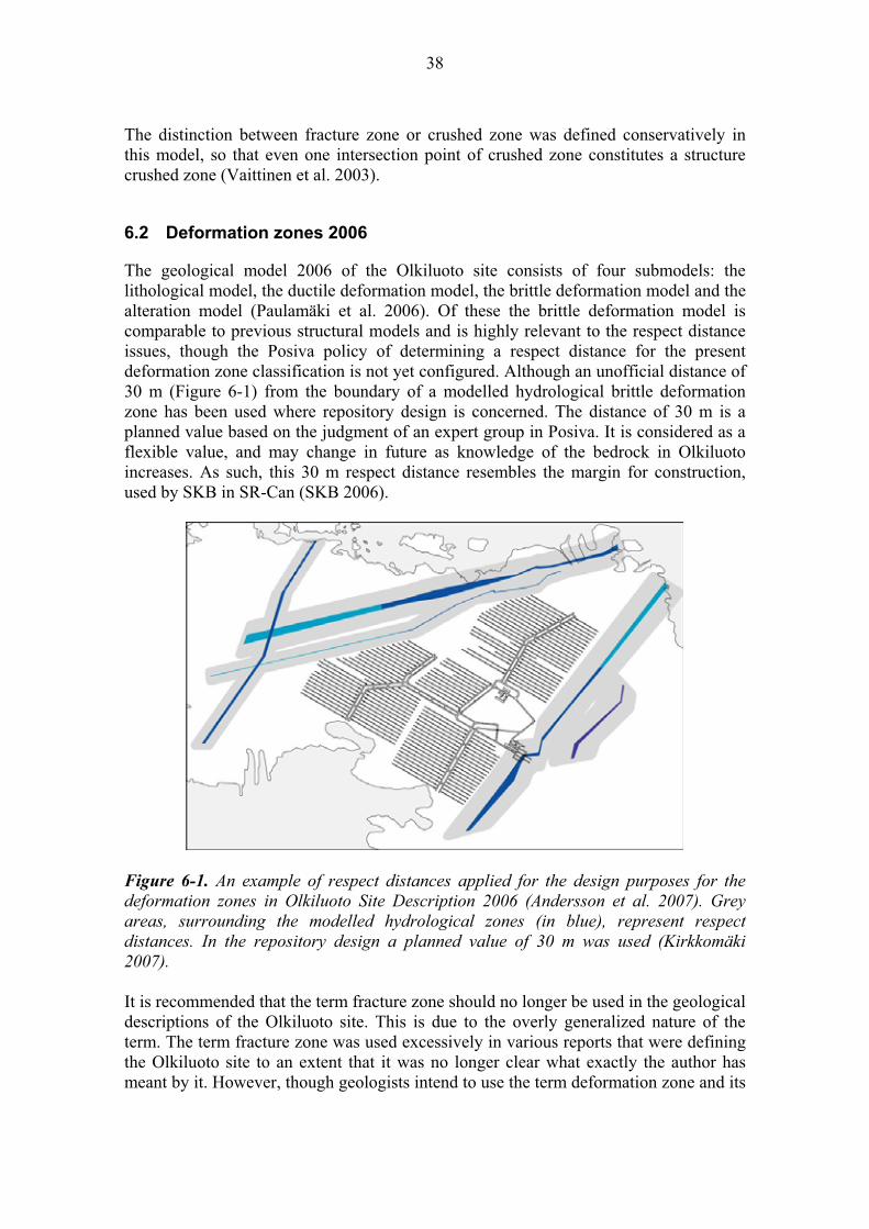
38
The distinction between fracture zone or crushed zone was defined conservatively in this model, so that even one intersection point of crushed zone constitutes a structure crushed zone (Vaittinen et al. 2003).
6.2 Deformation zones 2006
The geological model 2006 of the Olkiluoto site consists of four submodels: the lithological model, the ductile deformation model, the brittle deformation model and the alteration model (Paulamäki et al. 2006). Of these the brittle deformation model is comparable to previous structural models and is highly relevant to the respect distance issues, though the Posiva policy of determining a respect distance for the present deformation zone classification is not yet configured. Although an unofficial distance of 30 m (Figure 6-1) from the boundary of a modelled hydrological brittle deformation zone has been used where repository design is concerned. The distance of 30 m is a planned value based on the judgment of an expert group in Posiva. It is considered as a flexible value, and may change in future as knowledge of the bedrock in Olkiluoto increases. As such, this 30 m respect distance resembles the margin for construction, used by SKB in SR-Can (SKB 2006).
Figure 6-1. An example of respect distances applied for the design purposes for the
deformation zones in Olkiluoto Site Description 2006 (Andersson et al. 2007). Grey
areas, surrounding the modelled hydrological zones (in blue), represent respect
distances. In the repository design a planned value of 30 m was used (Kirkkomäki
2007).
It is recommended that the term fracture zone should no longer be used in the geological descriptions of the Olkiluoto site. This is due to the overly generalized nature of the term. The term fracture zone was used excessively in various reports that were defining the Olkiluoto site to an extent that it was no longer clear what exactly the author has meant by it. However, though geologists intend to use the term deformation zone and its

39
sub-classes (presented in Table 6-5) there is no guarantee that the term fracture zone will not appear in some future technical reports, as it has a long history in the previous structural models and is convenient to use in general discussions of the geology. As far as the author knows, SKB has embraced a similar policy concerning the fracture zones to that of Posiva, preferring to use the term deformation zone instead of fracture zone in present and future publications.
6.2.1 Classification of deformation zones at Olkiluoto
The methodology behind the structural modelling has recently changed, as the structural model no longer describes the mere brokenness of the rock, but all the geological characteristics of the structure that can reasonably be described. The reason for changing the modelling principles derives from the growing need to describe the Olkiluoto Site Area and the ONKALO area in as detailed and accurate a way as possible for the basis of further safety assessments. To this end, it was decided that all the possible geological data of the encountered intersections of deformation zones (in other words any features deviating from the "normal" host rock) would be recorded and classified according to the hierarchical system of deformation zones, created by Milnes et al. 2007. The systematic naming of the deformation zones was introduced in the geological model of the ONKALO area (Paananen et al. 2006) and is presented below in Table 6-5.

40
Table 6-5. Classification procedure for deformation zones at Olkiluoto (Milnes et al.2007).
Classification of deformation zones at Olkiluoto:
The zone shows intensive deformation, clearly more intensive than the wall rock on either side.
Deformation zone
The intersection is characterized by features, which indicate that the deformation took place under low PT conditions, lower than those under which the wall rock
was formed.
Low-grade deformation zone
The zone shows cohesionless or low-cohesive
deformation products: gouge, breccia, fractured rock and their partially or
wholly mineralized equivalents.
Brittle deformation zone
(Often called "fracture zones" in earlier reports)
The zone shows no clear signs of
lateralmovement.
Brittle joint
zone
(BJZ)
The zone shows clear signs of
lateralmovement.
Brittle fault
zone
(BFZ)
The zone shows cohesive
deformation products,:
cataclasites,preudotachylite,
welded crush rocks, etc. (typically massive and
structureless).
Semi-brittle
deformation zone
(SFZ)
The zone shows cohesive
deformation products: mylonites,
phyllonites, etc. (typically strongly
foliated).
Low-grade
ductile
deformation zone
(DSZ)
The zone is characterized by features which
indicate that the deformation took
place under high PT conditions, similar
to those under which the wall rock
was formed, showing cohesive
deformation products (e.g.
blastomylonites).
High-grade ductile
deformation zone
(HGZ)
Composite deformation zone: may contain any combination of the zones above.
The structures named fracture zones and R-structures in the previous structural models (Saksa 1993, Saksa et al. 1996, Paulamäki et al. 1996, Saksa et al 1998, Äikäs and Riekkola 2000, Vaittinen et al. 2001, Saksa et al. 2002, Vaittinen et al. 2003) are likely to be located at approximately the same locations as the present brittle fault zones (BFZ) or brittle joint zones (BJZ) in the geological models of Olkiluoto after 2006 (Paulamäki et al. 2006), although the widths of the deformation zones are likely to be more extensive. This is due to the inclusion of the influence zone to the intersection with the width of a deformation zone. The influence zone - the zone around the deformation zone core, in which mechanical damage and associated chemical and mineralogical

41
changes have occurred due to the process of faulting and may have relatively high hydraulic conductivity (McEwen 2002) - is mapped at least to an extent it is visible to the naked eye, and can be seen in geophysics. Previously, in drill core logging, the extent of a damage zone was considered and investigated (e.g. Hellä et al. 2001) as far as engineering geology is concerned, but it has not been included within the total zone width in the structural models.
Large fractures, which are always minor, small scale deformation zones by definition, may pose a risk to of canister failure due to secondary movements during major earthquakes if they crosscut deposition holes (e.g. Munier and Hökmark 2004); therefore the development of a methodology for the identification of long fractures is acknowledged as an important tool for the assessment of long-term safety of the repository. In the structural modelling after 2006, the aim is also to develop site-specific methods for the identification of minor deformation zones and long fractures. This requires detailed knowledge of the geological and geophysical properties of the features and their responses to different measurement techniques, such as radar, charged potential etc. (Posiva 2006).
The deformation zones in the present day geological model in Posiva do not contain any kind of description of the hydrogeological features that were included in the previous structural models (e.g. Vaittinen et al. 2003), as those are described in the hydrogeological model, which forms, like the geological model, part of the overall Site Descriptive Model (SDM) of Olkiluoto (Andersson et al. 2007). A brief introduction to hydrogeological zones in the hydrogeological model of SDM is given in following Chapter 6.2.2.
6.2.2 Hydrogeological zones
The hydrogeological model consists of the so-called hydrostructural model and flow model. This type of model is referred to as the descriptive hydrogeological model by SKB (see e.g. Rhén et al. 2003). The hydrostructural model is the geometrical distribution of the permeable features of the rock. It is clearly closely related to the geometrical structure of the geological bedrock model, but is not identical, and one of the future modelling tasks is to describe its relationship with the geological model (Andersson et al. 2007).
The geometrical structures, including the deformation zones of the geological model, are not necessarily identical to the geometrical structure of the hydrogeological model, therefore there became a need to introduce hydrogeological zones, which if simply put, combine geological features into less complex hydraulic ones. The geometries of the two models are naturally closely related. The groundwater simulation model with its boundary conditions and assigned hydraulic properties is called the flow model (Andersson et al. 2007). On some occasions the hydrogeological zones have been called Hydrological Zones (Posiva 2006).

42
6.3 Damage zone - influence zone
The extent of a volume around the deformation zone, influenced by the zone or part of it, was not included in the width of the structure in the structural models 1987-2005 of Olkiluoto, though the existence of such a zone has been under investigation in Posiva for quite some time (e.g. Saksa et al. 1993 and Hellä et al. (2001). The zone has been called by several names: the influence zone (Posiva 2006), fault damage zone or damage zone (McEwen 2002), boundary zone (Saksa et al. 1993), and in SKB transition zone (Munier et al. 2003). In the structural models following the model of 2006 (Paulamäki et al. 2006), the zone is included within the width of the observed deformation zone intersection, at least to the extent what is visible to the naked eye from the drillhole core or tunnel walls. Generally, in recent reports, the zone is referred to as the influence zone (e.g. Posiva 2006), which is the term that Posiva also intends to use in future.
In Saksa et al. (1993) each fracture zone, R -zone, was given a margin zone that was named R* (Figure 6-2). The R* in the model is the first description of an influence zone, or transition zone as termed in SKB, around a fracture zone in Olkiluoto. However, the R* zones were not defined for the structures in some of the following updates of the Olkiluoto structural model (Saksa et al. 1996, Paulamäki et al. 1996, Saksa et al. 1998, Anttila et al. 1999, Äikäs et al. 1999).
Figure 6-2. Representation of the margin areas of a fracture zone in Saksa et al. (1993). The influence zone is called the boundary zone in the figure.
An attempt to define influence zone for the structures in the structure model of 1998 (Saksa et al. 1998) was done also by Hellä et al. (2001). In their work, the influence zone was defined by? 8 drillhole core intersections for the modelled four structures. The parameters in the definition were: fracture density, aperture of a fracture and the number

43
of water conducting fractures. In the study, the influence zone ranged from 0 to 15 metres, being unequal in dimensions on the hanging wall and footwall. In Vaittinen et al. (2001) and in Saksa et al. (2002) the influence zone was defined as being a zone with a fracture frequency less than 10, but more than 7, surrounding the intersection of a fracture zone core ( 10 fractures/m) in the drillhole. In the Olkiluoto structure model of 2003 (Vaittinen et al. 2003), the influence zone is not included within the zone width. The HRC system has the Olkiluoto structure model of 2003 as the basis for defining respect distances (Hagros et al. 2005). As the influence zone was not an integrated part of the model according to the modelling practice at that time (see Chapter 6.1), Hagros et al. (2005) stated that the respect distance defined for the fracture zone must be in all cases large enough to take it into account.
Work is currently going on to define the influence zone for the deformation zones. The size of the influence zone around each fault is estimated based on geological and geophysical data and the information is then incorporated into the geological model. As the principles of structure modelling have changed significantly in Posiva, there is no statement yet of how the influence zone should be handled in practice in terms of canister positioning, though it is considered a relevant issue and at present various attempts to approach the matter are made.
The size of the influence zone has great implications, for example, for the definition of the respect distance to a fault and in the characterization of the internal structure of a fault as certain types of fractures close to a fault or certain parts of a fault may be highly conductive (Posiva 2006).
6.4 Scale
The terminology concerning the scale of the described deformation zones in the structural models of Olkiluoto have been somewhat incoherent and challenging to interpret when comparison to SKB's deformation zone scaling is made. The confusion derives from the variety of methods that are used when data from the structures of different sizes in the bedrock are acquired. In some cases the relative size, length and width, of the deformation zones are described according to the lineament interpretations (Table 6-6), in which case the most certain interpreted deformation zones are large, regional or local major deformation zones (Figures 6-3 and 6-4). In another case, which usually applies better at the local scale, the relative size of a deformation zone is based on the intersections in drillhole core logging. In the drillhole core logging the extent of the intersection, and even more so, the degree of brittle deformation, generally defines the size of the zone (Table 6-6).
The scaling of deformation zones is a linear continuity, a result of which the scale concepts of different methodologies, drillcore and indirect methods will inevitably intermingle. This inconsistency in methodologies related to different scales will most likely cause some problems for modelling also in future, no matter how much interface between drillhole logging and lineament interpretation is developed. Especially the scaling of the deformation zones observed by both methods can be problematic in future. Despite of this, an attempt to clarify the scale issue is made here. This is because
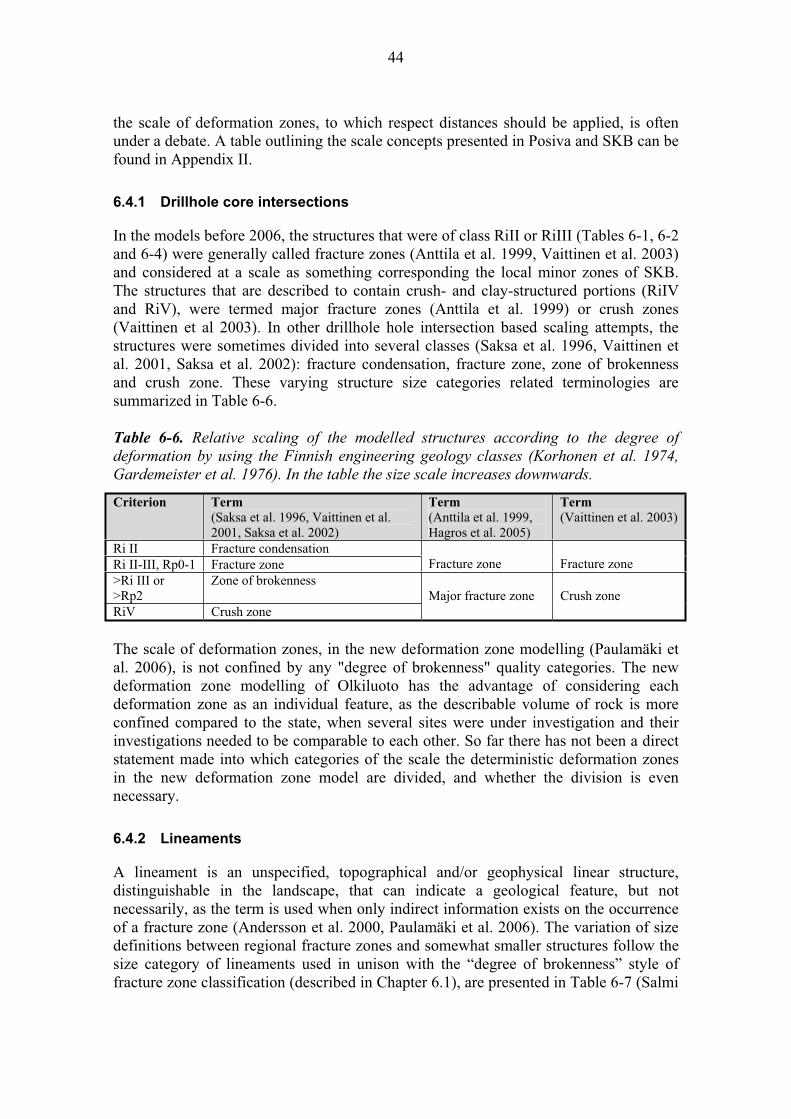
44
the scale of deformation zones, to which respect distances should be applied, is often under a debate. A table outlining the scale concepts presented in Posiva and SKB can be found in Appendix II.
6.4.1 Drillhole core intersections
In the models before 2006, the structures that were of class RiII or RiIII (Tables 6-1, 6-2 and 6-4) were generally called fracture zones (Anttila et al. 1999, Vaittinen et al. 2003) and considered at a scale as something corresponding the local minor zones of SKB. The structures that are described to contain crush- and clay-structured portions (RiIV and RiV), were termed major fracture zones (Anttila et al. 1999) or crush zones (Vaittinen et al 2003). In other drillhole hole intersection based scaling attempts, the structures were sometimes divided into several classes (Saksa et al. 1996, Vaittinen et al. 2001, Saksa et al. 2002): fracture condensation, fracture zone, zone of brokenness and crush zone. These varying structure size categories related terminologies are summarized in Table 6-6.
Table 6-6. Relative scaling of the modelled structures according to the degree of
deformation by using the Finnish engineering geology classes (Korhonen et al. 1974,
Gardemeister et al. 1976). In the table the size scale increases downwards.
Criterion Term
(Saksa et al. 1996, Vaittinen et al. 2001, Saksa et al. 2002)
Term
(Anttila et al. 1999, Hagros et al. 2005)
Term
(Vaittinen et al. 2003)
Ri II Fracture condensation Ri II-III, Rp0-1 Fracture zone Fracture zone Fracture zone >Ri III or >Rp2
Zone of brokenness
RiV Crush zone Major fracture zone Crush zone
The scale of deformation zones, in the new deformation zone modelling (Paulamäki et al. 2006), is not confined by any "degree of brokenness" quality categories. The new deformation zone modelling of Olkiluoto has the advantage of considering each deformation zone as an individual feature, as the describable volume of rock is more confined compared to the state, when several sites were under investigation and their investigations needed to be comparable to each other. So far there has not been a direct statement made into which categories of the scale the deterministic deformation zones in the new deformation zone model are divided, and whether the division is even necessary.
6.4.2 Lineaments
A lineament is an unspecified, topographical and/or geophysical linear structure, distinguishable in the landscape, that can indicate a geological feature, but not necessarily, as the term is used when only indirect information exists on the occurrence of a fracture zone (Andersson et al. 2000, Paulamäki et al. 2006). The variation of size definitions between regional fracture zones and somewhat smaller structures follow the size category of lineaments used in unison with the “degree of brokenness” style of fracture zone classification (described in Chapter 6.1), are presented in Table 6-7 (Salmi

45
et al. 1985, Kuivamäki 2001, La Pointe and Hermanson 2002) and Figure 6-3(Hakkarainen 1985, Kuivamäki and Vuorela 1985). In Table 6-7 the size classes of a lineaments are correlated to the expected size classes of a fracture zones, as well as to the terms used to describe such a zone. In the history of site investigations, when direct data of the bedrock was not available, these categories were used to define the size of the expected structure, in order to determine layout solutions, and as a consequence thereof, also respect distances. Note that the size classification scaling of the lineaments, which is presented in Table 6-7, is no longer in use in Posiva’s site describing modelling work.
Table 6-7. Size classification of lineaments according to Posiva reports (Salmi et al.
1985, Kuivamäki 2001, La Pointe and Hermanson 2002). The lineament class that
corresponds to the classes in Figure 6-3 is after Hakkarainen 1985, Kuivamäki and
Vuorela 1985.
Lineament
class
Width of a
fracture zone
Length Supposed depth extent of
the fracture zone
Term
(Hagros et al. 2005) I > 1 km 10 - 100km > 10 km II 100 - 1000 m 5 - 10 km 1 - 10 km
Regional fracture zone
III 10 - 100 m 2 - 5 km > 1 km Major fracture zone IV << 10 m 100 m - 2 km << 1000 m Minor fracture zone
The lineament interpretation in Figure 6-3 is old as is the size scaling of the predicted deformation zones within. Nevertheless, the size scales of the lineaments have been used as the respect distances have been assigned for deformation zone scales, e.g. in HRC (Hagros et al. 2005).
Figure 6-3. Bedrock structures determined for Olkiluoto during the site identification survey of 1983-1985 (in Anttila et al. 1999, modified after Hakkarainen 1985 and
Kuivamäki and Vuorela 1985). The classification size of lineaments, linked to the size of
interpreted structure, is presented in Table 6-7.

46
The way of describing deformation zones has evolved, as the understanding of the Olkiluoto bedrock has grown. The approach towards lineaments is less straightforward as it was in the beginning of site investigations in Olkiluoto. At the beginning, as there were fewer drillholes, lineament interpretation was a practical way of scaling the deformation zones. This enabled a simple and straightforward scaling for deformation zones that could be used as a basis when assigning respect distances to the design of proof prints. In the latest site model (Paulamäki et al. 2006), a new lineament interpretation is presented (Korhonen et al. 2005), which is less straightforward in relation to the sizing of the deformation zones. The new interpretation is made according to the lineament interpretation methodologies developed by SKB and it scales the probability of the existence of the zone, rather than a size of the expected deformation zone, although their modelled lengths do imply of their size. The present Olkiluoto lineament interpretation is presented in Figure 6-4.
Figure 6-4. Linked lineaments classified by their uncertainties (Korhonen et al. 2005).

47
In the latest Olkiluoto site report (Paulamäki et al. 2006), all modelled brittle fault zones and the brittle and semi-brittle fault and joint intersections observed in the investigation trenches have been checked against the lineament data but the correlation was rather poor. Regarding the location, one of the modelled fault zones has so far correlated with the lineaments. Probability for correlation regarding the location and size may still be high, as the locations of the lineaments on the island remain mostly covered with soft sediments and thus verification using direct observations may yet take place as the site investigations proceed.
The interface in scaling between the interpreted deformation zones and the ones modelled from the drillhole core intersections is problematic and a very relevant issue at present in Posiva. How do the modelled interpreted features compare with those encountered underground? That makes all the difference in the scaling of the deformation zones, and ultimately in determining realistic "respect distances" for deformation zones, for whatever scale these are considered appropriate to be determined.

48
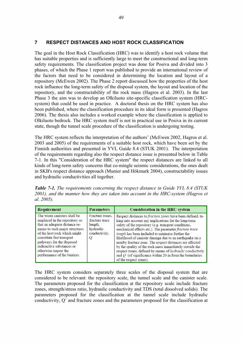
49
7 RESPECT DISTANCES AND HOST ROCK CLASSIFICATION
The goal in the Host Rock Classification (HRC) was to identify a host rock volume that has suitable properties and is sufficiently large to meet the constructional and long-term safety requirements. The classification project was done for Posiva and divided into 3 phases, of which the Phase 1 report was published to provide an international review of the factors that need to be considered in determining the location and layout of a repository (McEwen 2002). The Phase 2 report discussed how the properties of the host rock influence the long-term safety of the disposal system, the layout and location of the repository, and the constructability of the rock mass (Hagros et al. 2003). In the last Phase 3 the aim was to develop an Olkiluoto site-specific classification system (HRC-system) that could be used in practice. A doctoral thesis on the HRC system has also been published, where the classification procedure in its ideal form is presented (Hagros 2006). The thesis also includes a worked example where the classification is applied to Olkiluoto bedrock. The HRC system itself is not in practical use in Posiva in its current state, though the tunnel scale procedure of the classification is undergoing testing.
The HRC system reflects the interpretation of the authors’ (McEwen 2002, Hagros et al. 2003 and 2005) of the requirements of a suitable host rock, which have been set by the Finnish authorities and presented in YVL Guide 8.4 (STUK 2001). The interpretation of the requirements regarding also the respect distance issue is presented below in Table 7-1. In this "Consideration of the HRC system" the respect distances are linked to all kinds of long-term safety concerns that co-mingle seismic considerations, the ones dealt in SKB's respect distance approach (Munier and Hökmark 2004), constructability issues and hydraulic conductivities all together.
Table 7-1. The requirements concerning the respect distance in Guide YVL 8.4 (STUK
2001), and the manner how they are taken into account in the HRC-system (Hagros et
al. 2005).
The HRC system considers separately three scales of the disposal system that are considered to be relevant: the repository scale, the tunnel scale and the canister scale. The parameters proposed for the classification at the repository scale include fracture zones, strength/stress ratio, hydraulic conductivity and TDS (total dissolved solids). The parameters proposed for the classification at the tunnel scale include hydraulic conductivity, Q´ and fracture zones and the parameters proposed for the classification at

50
the canister scale include hydraulic conductivity, Q´, fracture zones, fracture width (aperture + filling) and fracture trace length (Hagros et al. 2005). Of these parameters, relevant for determining the HRC respect distances are at the repository and tunnel scale: the size of fracture zones, transmissivity (hydraulic conductivity) of the fracture zones, Q´-value of a fracture zone and at the canister scale, the size of a single fracture, including both width and trace length.
7.1 Extended classification of fracture zones in HRC
The respect distances defined in HRC were made to ensure that a potential transport route for radionuclides would not be directly from the canister to the fracture zone (Hagros et al. 2005). For this, the classification of structures in the Olkiluoto site model (Vaittinen et al. 2003) was "enhanced" to meet the demands of YVL Guide 8.4 by STUK (2001). The fracture zones were defined for classes A and B at the repository scale, and A to C at the tunnel scale that were given an instructive respect distance. The respect distances concerning each fracture zone class in the HRC system are subjective and based in each case on the experts' judgment, not on computations of any kind. The HRC-system fracture zone classification, regarding the respect distances is presented in Table 7-2.
Table 7-2. The HRC system fracture zone classification at Olkiluoto (Hagros 2006).
Any respect distances to Class A fracture zones apply to the central and deposition
tunnels and the deposition holes, any respect distances to Class B fracture zones apply
to the deposition tunnels and deposition holes and any respect distances to Class C
fracture zones apply only to the deposition holes.
Class Fracture zones in the class Basis for the definition of fracture
zone class
Respect
distance
A1 Length 10 km 80 m A Fracture zones that cannot be intersected by any part of the repository except for the access tunnels/shafts above the disposal depth.
A2 T400m 10-5 m2/s 50 m
B1 3 km length < 10 km 60 m
B2 10-6 m2/s T400m < 10-5 m2/s 40 m
B3 10-7 m2/s T400m < 10-6 m2/s 30 m
B Fracture zones that cannot be intersected by deposition tunnels (or deposition holes) but can be intersected by other parts of the repository.
B4 Q´ < 0.3 and thickness 5 m 15 m
C1 10-8 m2/s T400m < 10-7 m2/s 5 m
C2 Q´ < 0.3 and thickness < 5 m 4 m
C Fracture zones that can be intersected by deposition tunnels but cannot be intersected by deposition holes.
C3 T400m < 10-8 m2/s and Q´ 0.3 3 m
T400m = transmissivity at the reference depth level of 400 m Q´ = modified Q-value (rock mass quality)
Class A1 and B1 fracture zone respect distances concern the seismic risk, which is the basis of the SKB's respect distance term. In SKB the respect distance is applied to the fracture zones of 3 km trace length, which is the size scale of HRC system Class B1. The minimum respect distance in HRC is, however, different from SKB's minimum respect distance, which is 100 metres.
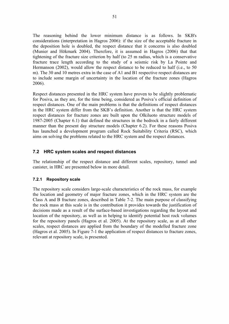
51
The reasoning behind the lower minimum distance is as follows. In SKB's considerations (interpretation in Hagros 2006): if the size of the acceptable fracture in the deposition hole is doubled, the respect distance that it concerns is also doubled (Munier and Hökmark 2004). Therefore, it is assumed in Hagros (2006) that that tightening of the fracture size criterion by half (to 25 m radius, which is a conservative fracture trace length according to the study of a seismic risk by La Pointe and Hermanson (2002), would allow the respect distance to be reduced to half (i.e., to 50 m). The 30 and 10 metres extra in the case of A1 and B1 respective respect distances are to include some margin of uncertainty in the location of the fracture zones (Hagros 2006).
Respect distances presented in the HRC system have proven to be slightly problematic for Posiva, as they are, for the time being, considered as Posiva’s official definition of respect distances. One of the main problems is that the definitions of respect distances in the HRC system differ from the SKB’s definition. Another is that the HRC system respect distances for fracture zones are built upon the Olkiluoto structure models of 1987-2005 (Chapter 6.1) that defined the structures in the bedrock in a fairly different manner than the present day structure models (Chapter 6.2). For these reasons Posiva has launched a development program called Rock Suitability Criteria (RSC), which aims on solving the problems related to the HRC system and the respect distances.
7.2 HRC system scales and respect distances
The relationship of the respect distance and different scales, repository, tunnel and canister, in HRC are presented below in more detail.
7.2.1 Repository scale
The repository scale considers large-scale characteristics of the rock mass, for example the location and geometry of major fracture zones, which in the HRC system are the Class A and B fracture zones, described in Table 7-2. The main purpose of classifying the rock mass at this scale is in the contribution it provides towards the justification of decisions made as a result of the surface-based investigations regarding the layout and location of the repository, as well as in helping to identify potential host rock volumes for the repository panels (Hagros et al. 2005). At the repository scale, as at all other scales, respect distances are applied from the boundary of the modelled fracture zone (Hagros et al. 2005). In Figure 7-1 the application of respect distances to fracture zones, relevant at repository scale, is presented.

52
Figure 7-1. Schematic illustration in a vertical plane through a repository panel and its
location, which is determined based on the classification at the repository scale. HRC
system Class A and B fracture zones and their related respect distances control the
location of the repository panel. (Hagros et al. 2005)
When the location and shape of a block, suitable for repository host rock is defined by using the repository scale HRC, one can move to a more detailed tunnel scale. In the HRC system the lineaments that surround the Olkiluoto Island are usually described as regional fracture zones at the repository scale (Hagros et al. 2005).
7.2.2 Tunnel scale
The classification of the host rock at the tunnel scale results in decisions regarding the locations and usability of deposition tunnels. The HRC system fracture zone classification and their respect distances for tunnel scale are the same for A and B Class fracture zones as at the repository scale (Table 7-2). To this Class C, which concerns mainly the mechanical stability of the host rock, is added at tunnel scale to describe the properties of minor fracture zones and their respect distances. All tunnel scale respect distances are applied from the boundary of the modelled fracture zone (Hagros et al. 2005).
In addition to the respect distances related to fracture zones, there are some quality requirements presented in HRC for the rock between the fracture zone and deposition hole, to which the respect distance should be extended if the quality is poor or the exact
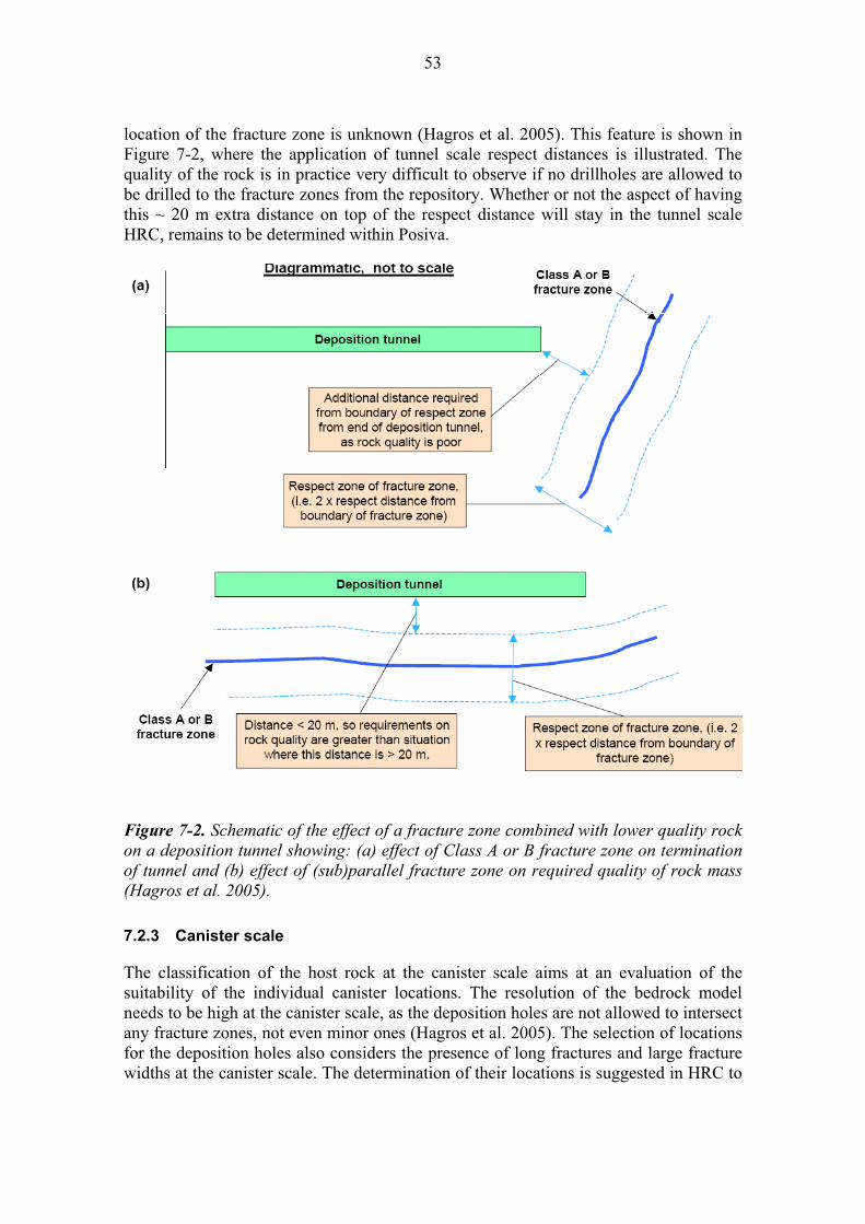
53
location of the fracture zone is unknown (Hagros et al. 2005). This feature is shown in Figure 7-2, where the application of tunnel scale respect distances is illustrated. The quality of the rock is in practice very difficult to observe if no drillholes are allowed to be drilled to the fracture zones from the repository. Whether or not the aspect of having this ~ 20 m extra distance on top of the respect distance will stay in the tunnel scale HRC, remains to be determined within Posiva.
Figure 7-2. Schematic of the effect of a fracture zone combined with lower quality rock
on a deposition tunnel showing: (a) effect of Class A or B fracture zone on termination
of tunnel and (b) effect of (sub)parallel fracture zone on required quality of rock mass
(Hagros et al. 2005).
7.2.3 Canister scale
The classification of the host rock at the canister scale aims at an evaluation of the suitability of the individual canister locations. The resolution of the bedrock model needs to be high at the canister scale, as the deposition holes are not allowed to intersect any fracture zones, not even minor ones (Hagros et al. 2005). The selection of locations for the deposition holes also considers the presence of long fractures and large fracture widths at the canister scale. The determination of their locations is suggested in HRC to

54
be based mainly on the detailed mapping of the tunnel floor and on the interpretation of the results of ground penetrating radar or other geophysical methods that study the fracture network below the tunnel floor.
If the tunnel is crosscut by a single fracture that has a trace length longer than 5-10 m, which is practically the tunnel perimeter, the tunnel section is unfavorable for disposal purposes and should not be selected as a provisional canister location, unless its suitability can be determined by more detailed studies (Hagros et al. 2005). The difference between fracture trace lengths of 5 m and 10 is that longer trace length results to stricter classification. The long fractures at the HRC canister scale resembles SKB's FPC, though the rule for discarding the deposition hole location is somewhat different in Posiva from that of SKB.
In Munier (2006) the deposition hole is discarded if it is crosscut by a single fracture that intersects the whole tunnel perimeter. In Posiva the maximum trace length of a fracture allowed to crosscut the deposition hole is > 10 m, unless it can be proven to have an actual trace length > 50 m, via some indirect measurements, e.g. geophysics (Hagros et al. 2005). Although, it might be the same in practice, whether the fracture is over 10 m long or observed to intersect the whole perimeter. At the HRC canister scale there are some discriminating parameters for deposition hole location other than fracture trace length that are not used in SKB. These are fracture width, water conductivity (K) and geotechnical property of the rock in the deposition hole walls (Q´-value). These are illustrated in Figure 7-3.
Figure 7-3. Canister locations that are discarded for use (Hagros et al. 2005).
The lack of supporting data from ONKALO, and the fact that the relationship between aperture and length has not been demonstrated convincingly anywhere (Cosgrove et al. 2006), has raised a discussion in the Olkiluoto Site about whether the width parameter should excluded from the canister scale classification in Posiva. No decisions, in one direction or another, has so far been made.
The effects of minor fracture zones and long individual fractures on locating deposition holes are shown in Figure 7-4. The protocol for deposition hole rejection at the canister scale resembles the present SKB's Full Perimeter Criterion (Figure 3-7) as the criterion

55
was inspired by the HRC. The rejection criteria in HRC and FPC in SKB are not however exactly synonyms.
Some controversies at the HRC canister scale exist regarding how to differentiate minor fracture zones from long fractures. As it is acknowledged that a long single fault may be a minor fracture zone in places (Cosgrove et al. 2006), the distinction between a minor fracture zone and a long single fracture seem rather artificial and somewhat impractical if the distinction is virtually impossible to make at the tunnel and canister scales.
Figure 7-4. An example of how the locations of deposition holes may need to be moved
due to unacceptable conditions. Two proposed canister locations are rejected due to a
long fracture and a Class C3 fracture zone (Table 7-2) (Hagros et al. 2005).
It is intended that the HRC system can be modified later, if required, as a result of more detailed site-specific data becoming available during the construction of ONKALO and during other detailed investigations carried out at the Olkiluoto site (Hagros et al. 2005). And there is a need for for modification, as the HRC classification was developed to match the older structural models, particularly the fracture zone models produced before2005. Today, a new geological model (Paulamäki et al. 2006) exists and the system of defining the deformation zones has changed significantly. For instance the hydro-geological zones are modelled separately, as it is understood that the hydrological conductivities may (but not necessarily) coincide with the deformation zones in Olkiluoto, and in that sense it would be false to describe them so. Earlier those were integrated into the structural model and were thus conveniently available for the HRC

56
system to apply. It has been decided that the HRC system, as well as the related respect distances, needs to be further defined and criteria rebuilt, taking into account e.g. the new modelling strategies (Posiva 2006). For this the RSC programme has been launched in Posiva in 2007.

57
8 DRILLHOLES AND RESPECT DISTANCE?
The material discussing the matter of drillholes and respect distances is derived from the presentation material by Pekka Anttila. The presentation was held in the Posiva and SKB joint seminar: Respect Distance Meeting, May 11-12, 2005.
For the ONKALO layout design, a basic requirement is that previous drillholes, drilled from the ground surface, do not penetrate the tunnel. In more detail this means that drillholes are not allowed to cut the tunnel already constructed, or to be constructed, in order to avoid harmful hydraulic connections between ONKALO and the ground surface, between ONKALO and water conducting structures in the bedrock or between different parts of ONKALO. Therefore the following instructions have been made concerning the area required around the drillholes, and the radius of this area has been termed respect distance on some occasions. The instructions are: - Minimum distance between the tunnel and planned drillhole is 10 m +
estimated measuring error. - Critical distance between ONKALO and drillhole is 5 m, and if this is crossed
a deviation report is written. - Minimum distance for planned drillhole is 30 m when used undirected
drilling. In other words, there needs to be a non-constructed space, a "respect distance", around the planned drillhole course that has radii of 30 m. The need for directed drilling is considered case by case.
On the whole, in the matter of respect distances, the case of drillholes is unrelated to the respect distances discussed in other forums. At present, in Posiva the majority of experts would prefer using some other term than respect distance for the drillholes in publications. For this purpose, a term: restricted radius is proposed here. The restricted radius required for the drillholes is illustrated in Figure 8-1. The thoughts behind the proposal are presented in detail in Chapter 9.5.
Figure 8-1. Proposed layout design for ONKALO. Red cylinder presents the restricted
radius for the borehole and the yellow spike in the middle is the hole itself.

58

59
9 DISCUSSION
At present the concerns related to the respect distances are similar in SKB and Posiva. Both agree that a respect distance should take into consideration seismic, hydraulic, mechanical and chemical properties of the modelled structures. To what the term respect distance is actually used to describe in practice is however quite different. The selection of a scale at which the respect distances are bound seems to be a factor that has a great impact on how the respect distances are defined in practice. In a way, it could be summarized that the divergence in the timing of the siting processes between Posiva and SKB has, among other things, lead to divergence in the respect distance concept.
SKB's priority up to this point has been to choose a site for the repository, which is served better by larger scale investigations and evaluations of the probabilities of having a good site. It is clearly stated in SKB that the respect distances regard only the seismic risk, as it overshadows the other effects on the scale at which the safety assessments are made. In practice this means that the respect distances are applied only to the deformation zones that are 3 km in size. However, SKB has also acknowledged the need to assign some distances for the deformation zones smaller than 3 km when sketching their layouts for the sites, as they have used a so-called margin for construction for this purpose (e.g. in Brantberger et al. 2006). These margins for constructions have been determined according to the mechanical and hydrological properties of the zone in question – in a quite similar style to Posiva’s use of respect distances (e.g. in Kirkkomäki et al. 2007) in the past.
Posiva's priority, on the other hand, is to prove that the site already selected after years of studies as appropriate for nuclear waste disposal purposes, actually is feasible. This demands detailed solutions to e.g. encountered deformation zones, in a long-term safety perspective. In Posiva respect distances have been assigned in practice according to their hydraulic properties, as it has been considered the most influential risk at the scale at which the Olkiluoto site is analysed. The seismic risk has been considered important when assigning respect distances in Posiva. For instance in La Pointe and Hermanson (2002) it is advised that the performance assessment should focus on identifying existing large deformation zones that could host large earthquakes in the future. The work on recognising these large zones is ongoing in the site.
9.1 Computation and subjectivity
A large number of reports written in Posiva deals with respect distances implemented in the modelled deformation zones of the site. These respect distances were usually assigned for design purposes to serve the planning of the excavated underground facilities. At present none of these previous definitions are officially "valid" as the overall modelling of the site is in a state of transformation. The actual dimensions of these respect distances have so far been based on the experts’ conservative, but nevertheless subjective, judgments.The situation is acknowledged in Posiva and efforts for improving the basis for the definition of respect distances at all scales (to deformation zones 3 km and to ones that are smaller) are planned for the future. This

60
work goes under the name of RSC-programme, and it aims at improving the criteria for the host rock required by the YVL 8.4 guideline.
In SKB the size of a critical radius for a given respect distance has been computed (Hökmark and Fälth 2006), thus the respect distances have been subjectively assigned, but the impact on the safety from the seismicity point of view objectively computed. Basically this means that the maximum size of a target fracture cutting the canister hole is computed for the distances of 0-100 m and 100-200 m from the deformation zone of
3 km. This criterion for assigning respect distances at the regional scale for the deformation zones 3 km is in SKB considered debatable. Criteria for the respect distances that would be based on computed data (other than from the seismic point of view) for the deformation zones < 3 km is has not yet been established.
9.2 Criteria for discrimination
What actually defines the fracture discriminating? Understanding the differences and similarities between the discrimination criteria presented in different safety assessment evaluations (e.g. FPC in Munier 2006 and critical fractures in Munier and Hökmark 2004) and the applications serving mainly the design (e.g. HRC, Hagros 2006) seems difficult, as the boundaries between the different theories are rather amorphous. To introduce the challenge, several criteria for (deposition hole) discrimination are summarised in Table 9-1.
Table 9-1. Criteria governing the size of a deposition hole discriminating fracture.
Discriminating fracture Report Scale
Trace
length
(radius)
Width
Deformatio
n zone
trace
length
Respect
Distance
Munier and Hökmark 2004
Regional 50 m 100 m
100 m 200 m
Munier 2006 Site FPCEFPC
Fälth and Hökmark (2006)
Regional 75 m 150 m
0-100 m 100-200 m
SKB
Brantberger et al. 2006
Site 75 m 150 m
3 km 0-100 m 100-200 m
Posiva La Pointe and Hermanson 2002
Repository 50 m **)
Repository Tunnel
25 m *) 3 - 10 km 10 km
60 m *)
80 m *)HRC Hagros et al. 2005
Hagros 2006
Canister 5 - 10 m 5 mm *) Subjective values, deduced for HRC system from the computations of La Pointe and Hermanson (2002) and Munier and Hökmark (2004).**) Computed lengths by using Wells and Coppersmith (1994) regression equations.
According to the Johan Anderson’s pers. comm.: “When discussing ‘respect distances’ or other criteria it is necessary to distinguish between ‘requirement’ (what condition is really not acceptable, e.g. fracture 150 m intersecting a deposition holes) and ‘criterion’ (what practically demonstrable rule should be applied to try to meet the

61
requirement, e.g. FPC). Generally, there are two issues that need to be considered (provided the requirement is right): 1) What is the risk of not meeting the requirement if the criterion is applied (e.g. FPC misses some long fractures) and 2) What is the risk of over predictions (e.g. applying FPC implies that holes intersected by fractures shorter than 150 m may also – unnecessarily - be taken out). This is a general problem in all diagnostic tasks. These different aspects are not clearly distinguished in the work of Hagros (2006) but will be the basis for Posiva’s new RSC-programme. And this is the reason why SKB at the same time talks about discriminating fractures and FPC as if they are not in conflict but simply describe the two approaches (requirement and criterion) on the same matter.”
At present FPIs (SKB) or TCFs (Posiva) is considered as a possible criterion in practice for the identification of a long, discriminating fracture in the tunnel. Regarding the different terms, FPI and TCF, for this same concept, there has been discussion in Posiva about adapting the SKB’s terminology and use the FPI for the purpose as well.
9.3 Deformation zones
9.3.1 Size issues
Quite much of the differences in the present day respect distances between Posiva and SKB seem to originate from the selected scale and the considerations related to it. SKB has an agreement that respect distances are applied to deformation zones 3 km. In Posiva the approach on the size issue is set out in the HRC system. However, the modelling strategy of the site has undergone significant changes very recently, and due to the changes several issues that relate to the Site Descriptive Model (Andersson et al. 2007), including respect distances, are re-evaluated. The re-evaluation of respect distances is related to the newly launched RSC programme, which was mentioned earlier in the text. The concrete issues, such as the size of the deformation zone to which respect distances should be applied, are to be defined in future by the RSC programme.
9.3.2 Transition zone / influence zone
Previously, attempts were made to constrain the extent of the transition zone by setting some threshold values of number of fractures/metre that the transition zone / influence zone in a drillhole core would have. At present the approach is no longer considered feasible, as e.g. the fracturing is recognized as a site-specific characteristic, and is therefore not suitable for universal criteria for determining the transition zone / influence zone. At present it appears that both SKB and Posiva, define the extent of the transition zone / influence zone for deterministic deformation zones according to the experts' judgment on a case-by-case basis.
The observations, on which the decisions of the zone extent are ultimately based, will most likely vary between (and within) each site. For one defined site, it might be possible to build some form of criteria for determining the transition zone / influence zone, which is naturally a goal. The likeliness of both Posiva and SKB having individual determination parameters for the transition zone / influence zone in the future
62
is great, though it does not need to affect the term itself. In other words, the transition zone / influence zone would continue to mean, in a broad sense, the area that is affected by the deformation zone core.
The ways of defining the transition zone / influence zone for each site, Posiva's current and SKB's future one, could then contain different characteristics, which should in each case be announced. Therefore the debates concerning the definition parameters of the transition zone / influence zone, and the efforts to unify them are pointless, as such a thing is unnecessary, if not virtually impossible. However, deciding which words (transition zone, fault damage zone, influence zone) are used in reports to describe the transition zone / influence zone, would be most convenient. It would save time and effort, as there would no longer be a need to explain why the term used for the same feature in general differs.
A similar approach that is suggested here for the to the transition zone / influence zone, might also be practical for overall respect distance concept.
It has been agreed in SKB that the transition zone is included in the width of the modelled deformation zone. SKB applies the respect distances from the boundary of the deformation zone, which means that the respect distance is applied from the transition zone boundary. The way of applying the respect distances in relation to the influence zones has not yet been established in Posiva. It will, however, be done during 2008.
9.4 Design application
The design of the repository is to what the respect distances will have the actual affect on. Regardless of according to which criteria's those are assigned. This means that what is meant by respect distances needs to be understood, not only by the experts responsible for the deformation zone modelling, but by the experts responsible for the engineering solutions as well. Furthermore, the regulators and reviewers also need to be able to follow the logic of assigning respect distances in order to comment on them.
Up to this point the design has been, according to their best judgments, following the instructions concerning the respect distances provided by the researchers in the form of reports. This goes for both SKB and Posiva. However, in the interpretation process, if the rules are not clearly defined, the result can be quite different from what was originally intended. Some examples of these kinds of not entirely accurate applications of respect distances can be found e.g. from Brantberger et al. (2006). Having a correct form of procedure when applying the respect distances would solve these kind of practical problems. In Posiva this aspect is considered in the future work of RSC programme.
The recently introduced SKB term "margin for construction" (Brantberger et al. 2006) resembles Posiva’s present-day definition of respect distance, particularly the ones used in the design (e.g. Kirkkomäki 2007). The margin for construction is also applied to smaller structures with a trace length 3 km, which is roughly the size scale of the deformation zones considered. However, it has been suspected by SKB's representatives

63
that the term margin for construction may not stay permanently in the SKB terminology.
Therefore, at least for the time being, the concept margin for construction should be understood more as a working title (the assigned distance, as well as the term itself, may change as the hypothesis behind and means of constraining it evolves), rather than as a requirement (the distance based on a theory that is supported by computations) for repository design purposes, which e.g. respect distance in SKB is.
As respect distances are expected to go through at least a certain of changes via the future work by the RSC programme, Posiva could perhaps use some kind of similar notation for the distances, applied by the design, that are not based on a measure backed up by the science. In other words, the design could use some other term, such as margin for construction, for the kind of temporary respect distances that are based on the experts’ judgment that is used (e.g. Kirkkomäki 2007).
9.5 Drillholes / boreholes
On the whole, the matter of respect distances, and the case of boreholes, is unrelated to the respect distances discussed in other forums. At present, the majority of experts in Posiva and SKB would prefer using some term other than respect distance for the drillholes / boreholes in publications. For this purpose, the term: restricted radius is proposed here. The word radius refers to the circular form of the area surrounding the drillhole / borehole that is described, and in so doing makes the mixing of the term, with some other safety concepts, that traditionally discuss areas or distances, more unlikely. The word restricted refers to the restrictions related to the near-areas of the drilled/bored holes. The word also impinges on our will to isolate the volume around the hole in order to avoid creating pathways for radionuclides to the biosphere. Otherpossibilities for describing this long-term safety aspect could be terms such as protective, exclusion, barrier or block, but the word restricted seemed most suitable for the purpose.

64
65
10 SUMMARY
1. SKB's respect distances consider the seismic risk, such that it overshadows the other effects considered (hydrological and mechanical properties). The respect distance is coupled with the size of a fracture where secondary slip could occur and which could intersect the proposed deposition hole location (Munier and Hökmark 2004).
2. Posiva's respect distances consider the seismic, hydrological and mechanical properties of the deterministic deformation zones as the most important issues to constitute a risk to the canister. These requirements for respect distances are an interpretation of those in STUK's YVL 8.4 Guide.
3. This seismic respect distance in SKB is determined for regional or local major deformation zones, as those are considered large enough to host M < 6 PGE (Munier and Hökmark 2004). The trace length of such a zone is defined as being
3 km. If deformation zone is shorter than 3 km, the margin for construction should be applied (Brantberger et al. 2006).
4. In Posiva the size of a deformation zone to what respect distances are applied vary from the regional to the local major and minor. At the different size scales the respect distances are assigned according to the most dominant risk (seismic, hydraulic, mechanical), e.g. in the HRC system (Hagros et al. 2005). The criteria given by the HRC system for respect distances are, however, due to change in the near future as Posiva’s Rock Suitability Criteria (RSC) programme proceeds.
5. At present respect distances are applied from the boundary of the modelled deformation zone in SKB. This modelled deformation zone also includes the transition zone. According to the Posivas HRC system the way of applying respect distances is from the boundary of the deformation zone core. This excludes the influence zone. This approach may, however change in future.
6. SKB defines the extent of the transition zone for deterministic deformation zones based on experts' judgment on a case-by-case basis. The information of whether or not the transition zone is included within the deformation zone widths is not generally stated in the reports. In Posiva the manner of dealing with influence zones is not yet standardized, though work for achieving criteria for defining an influence zone is in progress.
7. In future, when discussing respect distances, it is necessary to distinguish between “requirement”, what condition is really not acceptable, and “criterion”, what practically demonstrable rule should be applied to try to meet the requirement.
8. At present, the considerations regarding respect distance are emphasized differently in Posiva and SKB. Therefore, as long as the content of the term is not standardised, a distinction of what is meant by respect distance should be made whenever the term is used.

66
9. Drillholes / boreholes are unrelated to the respect distances discussed in other forums. For describing the distance to such holes, required for long-term safety aspects, the term restricted radius is proposed here.
67
REFERENCES
Andersson, J., Ström, A., Svemar, C., Almén K-E. & Ericsson, L. O. 2000. What requirements does the KBS-3 repository make on the host rock? Geoscientific suitability indicators and criteria for siting and site evaluation. Sweden: SKB TR-00-12, Svensk Kärnbränslehantering AB.
Andersson, J., Ahokas, H., Hudson, J.A., Koskinen, L., Luukkonen, A., Löfman, J., Keto, V., Mattila, J., Pitkänen, P., Ikonen, A. & Ylä-Mella, M. 2007. Olkiluoto Site Description 2006. Olkiluoto, Finland: Posiva Oy. POSIVA 2007-03.
Anttila, P., Ahokas, H., Front, K., Hinkkanen, H., Johansson, E., Paulamäki, P., Riekkola, R., Saari. J., Saksa, P., Snellman, M., Wikström, L. & Öhberg, A. 1999. Final disposal of spent nuclear fuel in the Finnish Bedrock - Olkiluoto site report. Helsinki, Finland: Posiva Oy. POSIVA 99-10.
Äikäs, K. & Riekkola, R. 2000. Locating the High Level Waste repository within the Olkiluoto site. Posiva Oy, Working Report 2000-52 (in Finnish).
Äikäs, K., Hagros, A., Johansson, E., Malmlund, H., Sievänen, U., Tolppanen, P., Ahokas, H., Heikkinen, E., Jääskeläinen, P., Ruotsalainen, P. & Saksa, P. 1999. Olkiluodon kallioperän luokittelu loppusijoitustilojen rakennettavuuden kannalta. Olkiluoto, Finland: Posiva Oy. Working Report 1999-55.
Bell, F.G. 1992. Engineering in rock masses. Butterworth-Heinemann Ltd., Oxford, p.54.
Brantberger, M., Zetterqvist, A., Arnbjerg-Nielsen, T., Olsson, T., Outters, N. & Syrjänen, P. 2006. Final repository for spent nuclear fuel. Underground design Forsmark, Layout D1, Sweden: SKB R-06-34, Svensk Kärnbränslehantering AB.
Bäckblom, G. & Munier, R. 2002. Effects of earthquakes on the deep repository for spent fuel in Sweden based on case studies and preliminary model results. Sweden: SKB TR-02-24, Svensk Kärnbränslehantering AB.
Börgesson, L. 1986. Model shear tests of canisters with smectite clay envelopes in deposition holes. Sweden: SKB TR 86-26. Svensk Kärnbränslehantering AB.
Börgesson, L., Johannesson, L-E. & Hernelind, J. 2004. Earthquake induced rock shear through a deposition hole. Effect on the canister and the buffer. Sweden: SKB TR-04-02, Svensk Kärnbränslehantering AB.
Cosgrove, J., Rosshoff, K., & Stanfors, K. 2006. Geological characteristics of deformation zones and a strategy for their detection in a repository. Sweden: SKB R-06-39, Svensk Kärnbränslehantering AB.
Cowie, P.A. & Scholtz, C. H. 1992. Displacement-length scaling relationship for faults; data synthesis and discussion. Journal of Structural Geology. Vol. 14(10): p 1149–1156.

68
Cowie P.A. & Shipton Z. K. 1998. Fault tip displacement gradients and process zone dimensions. Journal of Structural Geology. Vol. 20(8): p 983–997.
Fälth, B. & Hökmark H. 2006. Seismically induced shear displacement on repository host rock fractures. Results of new dynamic discrete fracture modeling. Sweden: SKB R-06-48, Svensk Kärnbränslehantering AB.
Gardemeister, R., Johansson, S., Korhonen, P., Patrikainen, P., Tuisku, T. & Vähäsarja, P. 1976. Application of the Finnish engineering geological classification (in Finnish). Espoo, Finland: Technical Research Centre of Finland, Geotechnical laboratory, Research note 25, 39 p.
Hagros, A., McEwen, T., Anttila, P.& Äikäs, K. 2003. Host rock classification. Phase 2: Influence of host rock properties. Olkiluoto, Finland: Posiva Oy. Working Report 2003-04.
Hagros, A., McEwen, T., Anttila, P.& Äikäs, K. 2005. Host rock classification. Phase 3: Proposed Classification System (HRC-system). Olkiluoto, Finland: Posiva Oy. Working Report 2005-07.
Hakkarainen, V. 1985. Olkiluodon ja sen ympäristön geologiset alueenvalinta-suositusten kannalta. Geologian tutkimuskeskus, Ydinjätteiden sijoitustutkimukset. TVO/KPA-loppusijoitus, Työraportti 85-09.
Hellä, P., Saksa., Karanko, A., Ahokas, H., Nummela, J. & Palmén, J. 2001. Determination of boundary zone for the structures in the bedrock model (in Finnish). Olkiluoto, Finland: Posiva Oy. Working Report 2001-34.
KBS, 1983a. Final storage of spent nuclear fuel – KBS-3. Summary. KBS-3 Summary, Swedish Nuclear Fuel Supply Co/Division, SKBF/KBS.
KBS, 1983b. Final storage of spent nuclear fuel – KBS-3. Part III Barriers. KBS-3 Part III, Swedish Nuclear Fuel Supply Co/Division, SKBF/KBS.
KBS, 1983c. Final storage of spent nuclear fuel – KBS-3. Part IV Safety. KBS-3 Part IV, Swedish Nuclear Fuel Supply Co/Division, SKBF/KBS.
KBS, 1983d. Final storage of spent nuclear fuel – KBS-3. Part II Geology. KBS-3 Part II, Swedish Nuclear Fuel Supply Co/Division, SKBF/KBS.
KBS, 1983e. Final storage of spent nuclear fuel – KBS-3. Part I General. KBS-3 Part I, Swedish Nuclear Fuel Supply Co/Division, SKBF/KBS.
Kearney, P. (ed.), Allen, P.A., Evans, A.M., Gouldie, A.S., Hallam, A., Park, R.G., Thorpe, R.S. & Vaughan, D.J. 1993. The Encyclopedia of Solid Earth Sciences. Oxford, Great Britain: Blackwell Scientic Publications. ISBN 0-632-02577-8.

69
Kirkkomäki, T. 2007. Loppusijoitustilojen asemointi ja vaiheittainen rakentaminen. Olkiluoto, Finland: Posiva Oy. Working Report 2006-92.
Knott, S. D., Beach, A., Brockbank, P. J., Brown, J. L., McCallum, J. E. & Welbon, A. I. 1996. Spatial and mechanical controls on normal fault populations, in Special issue; Scaling laws for fault and fracture populations; analyses and applications. Cowie, P.A., Knipe, R.J., Main, I.G., & Wojtal, S.F. (Editors). Pergamon: Oxford-New York, International. p. 359–372.
Korhonen, K-H., Gardemeister, R., Jääskeläinen, H., Niini, H. & Vähäsarja, P. 1974. Engineering geological bedrock classification (in Finnish). Espoo, Finland: Technical Research Centre of Finland, Geotechnical laboratory. 78 p. Research note 12.
Korhonen, K., Kuivamäki, A., Paananen, M. & Paulamäki, S. 2005. Lineament interpretation of the Olkiluoto area. Olkiluoto, Finland: Posiva Oy. Working Report 2005-34.
Kuivamäki, A. & Vuorela, P. 1985. Geologisten prosessien merkitys käytetyn ydinpolttoaineen loppusijoituksen kannalta, mallialueena Olkiluoto. Geologian tutkimuskeskus, Ydinjätteiden sijoitustutkimukset. TVO/KPA-loppusijoitus, Työraportti 85-12.
Kuivamäki, A. 2001. Olkiluodon alueellisen ruhjetulkinnan tarkistus. Olkiluoto, Finland: Posiva Oy. Working Report 2001-28.
Lagerbäck, R. 1988. Postglacial faulting and paleoseismicity in the Landsjärv area, northern Sweden. Sweden: SKB TR 88-25, Svensk Kärnbränslehantering AB.
La Pointe, P. & Hermanson, J. 2002. Estimation of rock movements due to future earthquakes at four candidate sites for a spent fuel repository in Finland. Helsinki, Finland: Posiva Oy. POSIVA 2002-02.
La Pointe, P., Wallmann, P., Thomas, A. & Follin, S. 1997. A methodology to estimate earthquake effects on fractures intersecting canister holes. Sweden: SKB TR 97-07, Svensk Kärnbränslehantering AB.
La Pointe, P. R., Cladouhos, T. & Follin, S., 1999. Calculation of displacements on fractures intersecting canisters induced by earthquakes: Aberg, Beberg and Ceberg examples. Sweden: SKB TR-99-03, Svensk Kärnbränslehantering AB.
McEwen, T. 2002. Host rock classification. Phase 1: The factors that determine the location and layout of a repository – a review. Olkiluoto, Finland: Posiva Oy. Working Report 2002-36.
McEwen, T. & Äikäs, T. 2000. The site selection process for a spent fuel repository in Finland - Summary report. Olkiluoto, Finland: Posiva Oy. POSIVA 2000-15.

70
Milnes, A.G., Aaltonen, I., Kemppainen, K., Mattila, J., Wikström, L., Front, K., Kärki, A., Gehör, S., Paulamäki, S., Paananen, M. & Ahokas, T. 2007. Geological Data Aquisition for Site Characterisation for the Phase of Underground Investigations. Olkiluoto, Finland: Posiva Oy. Working Report 2007-32.
Munier, R. 2006. Using observations in deposition tunnels to avoid intersections with critical fractures in deposition holes. Sweden: SKB R-06-54, Svensk Kärnbränslehantering AB.
Munier, R. & Hökmark, H. 2004. Respect distances. Rationale and means of computation. Sweden: SKB R-04-17, Svensk Kärnbränslehantering AB.
Munier, R., Sandstedt, H. & Niland, L. 1997. Förslag till principiella utformningar av förvar enligt KBS-3 för Aberg, Beberg och Ceberg. Sweden: SKB R-97-09, Svensk Kärnbränslehantering AB.
Munier, R., Stenberg, L., Stanfors, R., Milnes, A.G., Hermanson, J. & Triumf C-A. 2003. Geological Site Descriptive Model. A strategy for the model development during site investigations. Sweden: SKB R-03-07, Svensk Kärnbränslehantering AB.
Muir Wood, R., 1993. A review of the seismotectonics of Sweden. Sweden: SKB TR 93-13, Svensk Kärnbränslehantering AB.
Neuendorf , K.K.E,., Mehl, Jr. J.P. & Jackson, J.A. (eds). 2005. Glossary of Geology. Fifth edition. American Geological Institute, Alexandria, Virginia.
Paananen, M., Paulamäki, S., Gehör, S., Kärki, A., Front, K., Aaltonen, I., Ahokas, T., Kemppainen, K., Mattila, J. & Wikström, L. 2006. Geological Model of the ONKALO Area. Version 0. Olkiluoto, Finland: Posiva Oy. Working Report 2006-13.
Paulamäki, S., Front, K. & Heikkinen, E. & Ahokas, H. 1996. Eurajoen Olkiluodon kallioperän kuvaus ja mallit, yhteenvetoraportti. Olkiluoto, Finland: Posiva Oy. Working Report PATU-96-90.
Paulamäki, S., Paananen, M., Gehör, S., Kärki, A., Front, K., Aaltonen, I., Ahokas, T., Kemppainen, K., Mattila, J. & Wikström, L. 2006. Geological Model of the Olkiluoto Site. Version 0. Olkiluoto, Finland: Posiva Oy. Working Report 2006-37.
Peacock, D.C.P., Knipe, R.J. & Sanderson, D.J. 2000. Glossary of normal faults. Journal of Structural Geology, v. 22, no. 3, p. 291-305.
Peltonen, E., Vuori, S., Anttila, M., Hillebrand, K., Meling, K., Rasilainen, K., Salminen, P., Suolanen, V. & Winberg, M. 1985. Safety analysis of disposal of spent nuclear fuel – Normal and disturbed evolution scenarios (in Finnish). Nuclear Waste Commission of Finnish Power Companies, Report YJT-85-22.
Posiva 2003. ONKALO Underground Characterisation and Research Programme (UCRP). Olkiluoto, Finland: Posiva Oy. POSIVA 2003-03.
71
Posiva 2006. TKS-2006. Nuclear Waste Management of the Olkiluoto and Loviisa Power Plants: Programme for Research, Development and Technical Design for 2007-2009. Olkiluoto, Finland: Posiva Oy.
Rhén, I., Follin, S. & Hermanson, J. 2003. Hydrogeological Site Descriptive Model – a strategy for its development during Site investigations. Sweden: SKB R-03-08, Svensk Kärnbränslehantering AB.
Riekkola, R., Saanio, T., Öhlberg, A. & Salo, J-P. 1992a. Preliminary locating of the repository for spent nuclear fuel within the Olkiluoto site (in Finnish). Finland: Teollisuuden Voima Oy, TVO/KPA-T&T, Working Report 92-05.
Riekkola, R., Oksanen, J., Kokko, M., Saanio, T. & Salo, J-P. 1992b. Comparison for construction of TVO’s final disposal facility at the five investigation sites (in Finnish). Finland: Teollisuuden Voima Oy, TVO/KPA-T&T, Working Report 92-09.
Riekkola, R., Saanio, T. & Salo, J-P. 1996. Preliminary site-specific adaptations of the repository for spent nuclear fuel (in Finnish). Finland: Posiva Oy, Report TEKA-96-07.
Rutter, E.H., 1986. On the nomenclature of mode of failure transitions in rocks. Tectonophysics, v. 122, p. 381-387.
Saksa, P.(Ed.), Ahokas, H., Paananen, M., Paulamäki, S., Anttila, P., Front, K., Pitkänen, P., Hassinen, P. & Ylinen, A. 1993. Bedrock model of the Olkiluoto area, summary report. Nuclear Waste Commission of Finnish Power Companies. Report YJT-93-15. Helsinki ISSN 0359-548X.
Saksa, P., Nummela, J. & Ahokas, H. 1996. Eurajoen Olkiluodon tutkimusalueen kalliomalli, täydennetty ja tarkennettu vuoden 1996 kuvaus. Finland: Posiva Oy, Working Report PATU-96-46.
Saksa, P, Ahokas, H., Nummela, J. & Lindh, J. 1998. Kivetyn, Olkiluodon ja Romuvaaran kalliomallit, rakennemallien muutokset v. 1997. Helsinki, Finland: Posiva Oy. Työraportti 98-12.
Saksa, P., Vaittinen, T. & Nummela, J. 2002. Tutkimusalueen länsiosan rakenteiden täydentävä tarkastelu, kalliomalli v. 2001/2. Olkiluoto, Finland: Posiva Oy. Working Report 2002-46.
Salmi, M., Vuorela, P. & Kuivamäki, A. 1985. Käytetyn ydinpolttoaineen loppu-sijoituksen geologiset alueenvalintatutkimukset. Geologian tutkimuskeskus, Ydinjätteiden sijoitustutkimukset. Raportti YJT-85-27.
Scholz, C. H. 1990. The mechanics of earthquakes and faulting. 1990, USA: Cambridge University Press USA. ISBN.
SKB, 1992. SKB-91. Final disposal of spent nuclear fuel. Importance of bedrock for safety. Sweden: SKB TR 92-20, Svensk Kärnbränslehantering AB.

72
SKB, 1999. Deep repository for spent nuclear fuel. SR 97 – Post-closure safety. Main report – Volume I, Volume II and Summary. Sweden: SKB TR-99-06, Svensk Kärnbränslehantering AB.
SKB, 2004. Interim main report of the safety assessment SR-Can. Sweden: SKB TR-04-11, Svensk Kärnbränslehantering AB.
SKB, 2006. Long-term safety for KBS-3 repositories at Forsmark and Laxemar - a first evaluation. Main report of the SR-Can project. Sweden: SKB TR-06-09, Svensk Kärnbränslehantering AB.
Stanfors, R. & Ericsson, L. O. 1993. Post-glacial faulting in the Lansjärv area, Northern Sweden. Comments from the expert group on a field visit at the Molberget post-glacial fault area, 1991. Sweden: SKB TR 93-11, Svensk Kärnbränslehantering AB.
STUK 2001. Long-term safety of disposal of spent nuclear fuel. Guide YVL 8.4. Finnish Radiation and Nuclear Safety Authority (STUK). Finland, 23.5.2001. 9 p.
Takase, H., Benbow, S. & Grindrod, P. 1998. Mechanical failure of SKB spent fuel disposal canisters. Mathematical modelling and scoping calculations. Sweden: SKB TR-99-34, Svensk Kärnbränslehantering AB.
Thunehed, H. & Lindqvist, L. 2003. Oskarshamn site investigation. Calculation of Fracture Zone Index (FZI) for KSH01A. Sweden: SKB P-03-93, Svensk Kärnbränslehantering AB.
Vaittinen, T., Saksa, P., Nummela, J., Palmén, J., Hellä, P., Ahokas, H. & Keskinen, J. 2001. Olkiluodon kalliomalli, täydennetty kuvaus v. 2001/1. Olkiluoto, Finland: Posiva Oy. Working Report 2001-32.
Vaittinen, T., Ahokas, H., Heikkinen, E., Hellä, P., Nummela, J., Saksa, P., Tammisto E., Paulamäki, S., Paananen, M., Front, K. & Kärki, A. 2003. Bedrock model of the Olkiluoto site, version 2003/1. Olkiluoto, Finland: Posiva Oy. Working Report 2003-43.
Vermilye, J. M. 1996. The growth of natural fracture systems: A fracture mechanics approach. PhD thesis. Colombia University.
Vermilye, J. M. & Scholz, C. H. 1998. The Process zone. A microstructural view of fault growth. J. Geophys. Res. Vol. 103(B6): p 12223–12237.
Wells, D. L. & Coppersmith, K. J. 1994. New empirical relationships among magnitude, rupture length, rupture width, rupture area, and surface displacement. Bulletin of the Seismological Society of America. Vol. 84(4): p 974–1002.
Werme, L. O. & Sellin, P. 2001. The performance of a copper canister for geologic disposal of spent nuclear fuel in granitic rock. Sweden: SKB, Svensk Kärnbränslehantering AB.

73
Werme, L. O. & Sellin, P. 2003. The performance of a copper canister for geologic disposal of spent nuclear fuel in granitic rock, In: Prediction of long term corrosion behaviour in nuclear waste systems. Proceedings of an international workshop Cadarache France 2002. pp 395–411. Sweden: Svensk Kärnbränslehantering AB.

74

75
APPENDIX I: GLOSSARY OF TERMS RELATED TO RESPECT DISTANCE
There is a numerable amount of geological terms that are used in relation to respect distance. The terms mentioned in the context of SKB’s and Posiva’s respect distances are summarised below and the terms having incongruous definitions, or is only used by one of the parties are marked by*. If available, an internationally accepted definition for a term is presented first, and the definition distinctive to Posiva and SKB is follows it. The definitions or the use of the listed terms may change in the future in both SKB and Posiva.
B
Brittle deformation
The term “brittle” is applied to the types and effects of deformation in which rock failure takes place suddenly by fracture at peak strength, without any plasticity. The mechanism by which brittle deformation occurs includes the formation and growth of fractures and frictional sliding (Neuendorf et al. 2005). Previously Posiva and SKB used the term “fracture zone” to designate all different types of deformation zones where the deformation has been mainly of a brittle character. See also: fracture zone.
C
Canister failure criterion
Canister failure criterion is the maximum displacement across the canister that the canister-bentonite buffer system can withstand and yet maintain its isolating capability (Börgesson 1986, Takase et al. 1998, Werme and Sellin 2001, 2003, Munier and Hökmark 2004). To ensure compatibility between various models, SKB uses the criterion of 0.1 m shear displacement across the canister position (Munier and Hökmark 2004), although it is considered overly conservative (Börgesson et al. 2004).
Critical fracture*
Critical fracture is a fracture in the repository volume that may have a trace length sufficient to host a slip, exceeding the canister failure criterion, whereas the fracture is a discriminating fracture for deposition hole position (Cosgrove et al. 2006). See also: discriminating fracture, FPI, FPC and EFPC.
Composite deformation zone*
In SKB the deformation zones, which show evidence of both brittle and ductile deformation, are called composite deformation zones (Cosgrove et al. 2006). In Posiva the composite deformation zone is included in the deformation zone classification system, where it stands for any combination of different deformation zones at the same location.
76
Core, fault core, central core
The core is the most deformed part of the (brittle) deformation zone that has, in general, clay filled fractures, breccia, cataclasites and other results of shear deformation (Munier and Hökmark 2004). The core is usually surrounded by a damage zone, that can have higher conductivity than unfaulted rock mass. The core itself can have relatively low hydraulic conductivity, depending on the quantity and quality of the filling (McEwen 2002). SKB and Posiva have a similar use for the core of the deformation zone.
D
Damage zone, influence zone (Posiva), transition zone (SKB)*
Internationally known term; the damage zone is a zone around the fault, typically caused by accumulation of displacement on a fault as well as fault propagation and linkage (Peacock et al. 2000). The damage zone can have relatively high hydraulic conductivity in crystalline rocks (McEwen 2002) but not necessarily. This zone is called the influence zone in Posiva’s (Paananen et al. 2006) and the transition zone in SKB’s publications (e.g. Munier and Hökmark 2004). The influence zone / transition zone is included in the width of a deformation in both SKB and Posiva, though the features defining the influence zone / transition zone may differ on both sides. The damage zone is sometimes referred also as: the zone of influence (Paulamäki et al. 2006), fault damage zone (McEwen 2002), process zone (Munier et al. 2003, Thunehed and Lindqvist 2003) and boundary zone (Hellä et al. 2001).
Deformation zone*
The term deformation zone is used to designate an essentially 2-dimensional structure (small thickness relative to its lateral extent) in which deformation has been concentrated. If there is sufficient geological information, deformation zones can be further qualified either as in SKB: brittle, ductile or composite (Cosgrove et al. 2006), or as in Posiva: brittle, semi-brittle, low-grade ductile, high-grade ductile and composite, which covers any combination of different types of deformation (Paulamäki et al. 2006). The commonly used term "fracture zone" can be used to denote a brittle deformation zone. The commonly used term "ductile shear zone" can be used to denote a ductile deformation zone (Cosgrove et al. 2006).
Degree-of-utilisation, utilization ratio, resource ratio, exploitation ratio*
Degree-of-utilisation is a measure, used by SKB, on how much of the rock is available for deposition and is expressed as a ratio between the amount of canister positions that can be accepted for loading and the total amount of canister positions (Munier and Hökmark 2004). The degree-of-utilisation (Munier 2006) has also been referred to as resource ratio (Munier and Hökmark 2004) and sometimes written in a form as utilisation ratio (Brantberger et al. 2006). Degree-of-utilisation can be expressed as:
Ncan
Degree-of-utilisation [%]= Npos
x 100

77
Where:
Ncan is the number of canistersNpos the total amount of canister positions
Discontinuity
Internationally a discontinuity is known as a surface separating two unrelated groups of rocks e.g. fault or an unconformity. The term discontinuity makes no distinctions concerning the age, geometry or mode of origin of the feature (Neuendorf et al. 2005). In engineering fields, discontinuities are often used to designate fracture zones (Andersson et al. 2000). In geology, instead of discontinuities terms such as fractures, faults, joints or deformation zones, depending on the scale, are preferred. In SKB’s use discontinuity is synonymous to the terms structure and zone of weakness (Andersson et al. 2000).
Discriminating fracture*
Discriminating fracture is a fracture that intersects the designed deposition hole position and is considered large enough to host a slip exceeding canister failure criterion. It is a target fracture that crosscuts the proposed deposition hole perimeter and has unacceptable trace length (used e.g. in Munier and Hökmark 2004 and Hagros et al. 2005). See also FPC and EFPC.
Ductile deformation
Ductile deformation is a response of a rock to stress in which the rock appears to have deformed without the loss of continuity at the scale of observation (Rutter 1986).
E
Engineered Barrier System, EBS
Engineered Barrier System, EBS, is the copper canister and the bentonite filling in the disposal hole, surrounding the canister, which is based on the KBS-3 concept (KBS 1983a-e). Posiva and SKB use the term in a similar manner.
Expanded Full Perimeter Criterion, EFPC*
In SKB the FPC was found insufficient to detect all potentially discriminating fractures, and thus it was complemented with a new criterion, EFPC, which also addresses large fractures in the immediate vicinity of the tunnel that remain undetected by tunnel mapping. Unless stated otherwise, the criterion considers discriminating also all fractures that intersect 5 or more canister positions (Munier 2006). See also discriminating fracture and FPC.

78
F
Fracture
Fracture is a general term for any surface within a material across which there is no cohesion, e.g. a crack. Fracture includes cracks joints and faults (Neuendorf et al. 2005).
Fracture zone
Fracture zone is a tabular zone that generally has lower mechanical strength and a higher permeability than the rest of the rock. Previously SKB used the term fracture zones to designate all different types of deformation zones where the deformation has been of a brittle character (Andersson et al. 2000, Cosgrove et al. 2006). Fracture zones were also sometimes referred to as structures, zone of weaknesses or discontinuities (Andersson et al. 2000). Previously Posiva used fracture zones in a similar manner to SKB. These fracture zones were also denoted as fault zones, crushed zones, R-structures or RH-structures (e.g. in Vaittinen et al. 2003). Both Posiva and SKB prefer not to use the term fracture zone, and instead to use the term brittle deformation zones to designate such zones.
Fault zone
Fault zone is expressed as a zone of numerous small fractures and incohesive fault products: fault gouge and/or fault breccia (Neuendorf et al. 2005).
Fault
Fault is a discrete surface or zone of discrete surfaces separating two rock masses across which one mass has slid past the other (Neuendorf et al. 2005).
Full Perimeter Criterion, FPC*
The Full Perimeter Criterion is used in SKB’s safety assessment to evaluate the possibility of losing disposal space due to existence of a long fracture. The criterion assumes that a fracture that intersects the whole tunnel perimeter (FPI) has a critical trace length and therefore is a discriminating fracture, if it intersects deposition hole (Munier 2006). FPI requires repositioning of a deposition hole, which lessens the degree-of-utilisation of a disposal facility. See also: discriminating fracture and EFPC.
Full Perimeter Intersection, FPI*
Full Perimeter Intersection, FPI, is a fracture that cuts the whole tunnel perimeter (Munier 2006). Similar structures are named Tunnel Crosscutting Fracture, TCF, in the systematic tunnel mapping in Posiva.
G
Geotechnically significant fracture zone
Geotechnically significant fracture zones have typically very low Q-value (< 1 at 400 m depth), according to engineering determination. The term has been used in some
79
previous structural models concerning Olkiluoto (e.g. Vaittinen et al 2003) modelled, deterministic brittle deformation zones. The term should no longer be used. See also: R-structures
H
H-structure, RH-structure, HZ*
RH-structures sometimes presented as H-structures or R-structures with -HY -suffix, depending on the model, are terms that have been used in Posiva in the Olkiluoto structural model reports up to 2005 (Vaittinen et al. 2003) to represent a structure that is considered hydrogeologically significant. The prefix RH is followed by a running number (for example RH12), which defines each individual modelled zone. Some of the most well known RH -structure names are still in use in present day reports, as proper names, although the naming system is no longer used. In the Posiva’s Site Report 2006 (Andersson et al. 2007) these hydrologically significant structures are named hydrogeological zones and are usually presented abbreviated to HZ. The numbers attached to the HZ abbreviation relate to both structure models prior to 2005 (e.g. HZ20 is derived from the RH20) and to deformation zone models post 2006 (e.g. HZ100 is derived from the BFZ100).
I
Intact rock*
Intact rock mass is used to refer to the averagely fractured rock mass lying between the fracture zones. Before 2004 it was used in this sense in many Posiva reports. Since 2003 in Posiva (the UCRP-programme, Posiva 2003) the combination “intact rock + fractures”, whether the fracturing is of average intensity or not, the term rock mass will be used, following the international usage. See also: rock mass.
Intersection
Intersections are the data points (or short data lines) on which the geological 3D site model must be based, and they should remain fixed, however much the model is revised or modified, and whatever alternative models are considered. The documentation of intersections is the main focus of geological data acquisition for the geological modelling. In general, tunnel intersections provide a much higher quality of geological data for 3D modelling than drillholes (Milnes et al. 2007 in prep.).
J
Joint
Joint is a planar fracture, crack, or parting in a rock, without shear displacement. The surface of a joint is usually decorated with a plumose structure. Joints occur often as a parallel joint set (Neuendorf et al. 2005).
80
L
Lineament
Internationally a lineament is a linear topographic feature of regional extent that is believed to reflect crustal structure (Neuendorf et al. 2005). In SKB and Posiva the term lineament is used for an unspecified, topographically and/or geophysically distinguishable linear structure in the landscape (Andersson et al. 2000, Paulamäki et al. 2006). Lineaments can indicate a geological feature, but not necessarily as the term is used when only indirect information exists on the occurrence of a fracture zone. Lineament is synonymous to interpreted fracture zone (Andersson et al. 2000).
M
Moment magnitude, M, (Mw)*
Moment magnitude is the earthquake size calculated from the seismic moment of an earthquake. This measure is the most valid size calculation for earthquakes above Richter or body wave magnitude 7-7.5. Internationally the symbol for moment magnitude is Mw (Neuendorf et al. 2005), in SKB the symbol M is used to denote moment magnitude when computing respect distances (e.g. in Munier and Hokmark 2004). M approximates other magnitude measurements, for instance the Richter magnitude, reasonably well (Thatcher and Hanks 1973).
Margin for construction*
Margin for construction is a concept used by SKB, when planning the layout of a probable repository at the site. Margin of construction is the area that surrounds the major deformation zones of the site, where the deposition of canisters is not allowed (Brantberger et al. 2006). Margin for construction can be presented as a formula:
thickness of a deformation zone + variation in thickness Margin for construction =
2+ safety margin (SM)
Margin of construction resembles the respect distances used in Posiva design oriented reports.
P
Post-Glacial Earthquake, PGE
Post-glacial pertains to the time interval since the total disappearance of continental glaciers in middle latitudes or especially from some particular area (Neuendorf et al. 2005). Post-glacial faulting is caused by earthquakes that occur in response to changes in stress field due to crustal unloading after an ice age. Post-glacial earthquakes can occur in regions where there is no historical record of seismicity that generates surface faulting. To date, all examples of postglacial faulting have involved reactivation of existing faults and fractures. PGEs are often referred to as post-glacial faulting, glacio-isostatic faulting, glacial rebound faulting and glaciotectonics.

81
R
R-structure*
R-structure is a term used in Posiva’s previous structural models of the Olkiluoto site (e.g. Vaittinen et al. 2003). R-structures are local fracture zones, either major or minor, that are classified according to the Finnish Engineering Geology classification’s Ri-system (Korhonen et al. 1974, Gardemeister et al. 1976). Parameters that were used in the classification are: an increase of fracture density, and/or to alteration of the rock mass. In the Olkiluoto structural models (Anttila et al. 1999 and Vaittinen et al. 2003), the letter R is followed by a number (for example R19), defining each modelled zone. For R-structure having hydrological significance the combination of RH is sometimes used. The R-structure nomenclature was used in Posiva until the structural model of 2003 (Vaittinen et al. 2003); in the present system R-structures correspond brittle reformation zones. The Finnish Engineering Geology classification is still used in Posiva’s present geological data acquisition methods, although the weighting upon it is less dominating.
Respect volume
Respect volume is a 3D respect distance space between the deposition tunnel and deformation zone. Uncertainty in the position of a deformation zone will reflect on the positioning and the size of a respect volume (Munier and Hökmark 2004).
Rock mass
Rock mass is a term, used especially for engineering purposes, that includes a volume of earth material, including rock, soil, water, air-filled voids and the discontinuities that divide it (Bell 1992). The behaviour of a rock mass is determined, to a large extent, by the type, spacing, orientation and the characteristics of the discontinuities present (Neuendorf et al. 2005). See also: intact rock.
S
Seismic influence
Seismic influence is the activation in the structure due to an earthquake that causes a slip in a target fracture intersecting the deposition hole that might damage the isolation capacity of the canister and thereby jeopardize the overall integrity of the barrier system. In SKB’s and Posiva’s considerations, the seismic influence would be caused by a PGE (Munier and Hökmark 2004, Hagros et al. 2005).
Seismic influence distance*
Seismic influence distance is the distance from the rupture zone that is capable of accommodating the seismic energy released from earthquake of ~ M6 – M8 (Munier and Hökmark 2004).

82
Structure
Structure is the general disposition, attitude, arrangement, or relative positions of the rock masses of a region or area; the sum total of the structural features an area, consequent upon such deformational processes as faulting, folding and igneous intrusion (Neuendorf et al. 2005). Structure is any geological feature that can be defined geometrically (Kearney et al. 1993, Anttila et al. 1999).
T
Target fracture, reference target fracture*
In SKB the fractures in the host rock are called target fractures or, in some cases, reference target fractures. When modelling, target fractures are given: orientation (strike and dip), mechanical properties (friction), size and distance to rupture area. In all simulations so far target fractures have been planar discs or rectangles (Munier and Hökmark 2004).
Tunnel Cross-cutting Fracture, TCF*
Tunnel Cross-cutting Fracture is in Posiva a fracture that cuts the whole tunnel perimeter (Milnes et al. 2007). It is a synonym to FPI, used by SKB (Munier 2006).
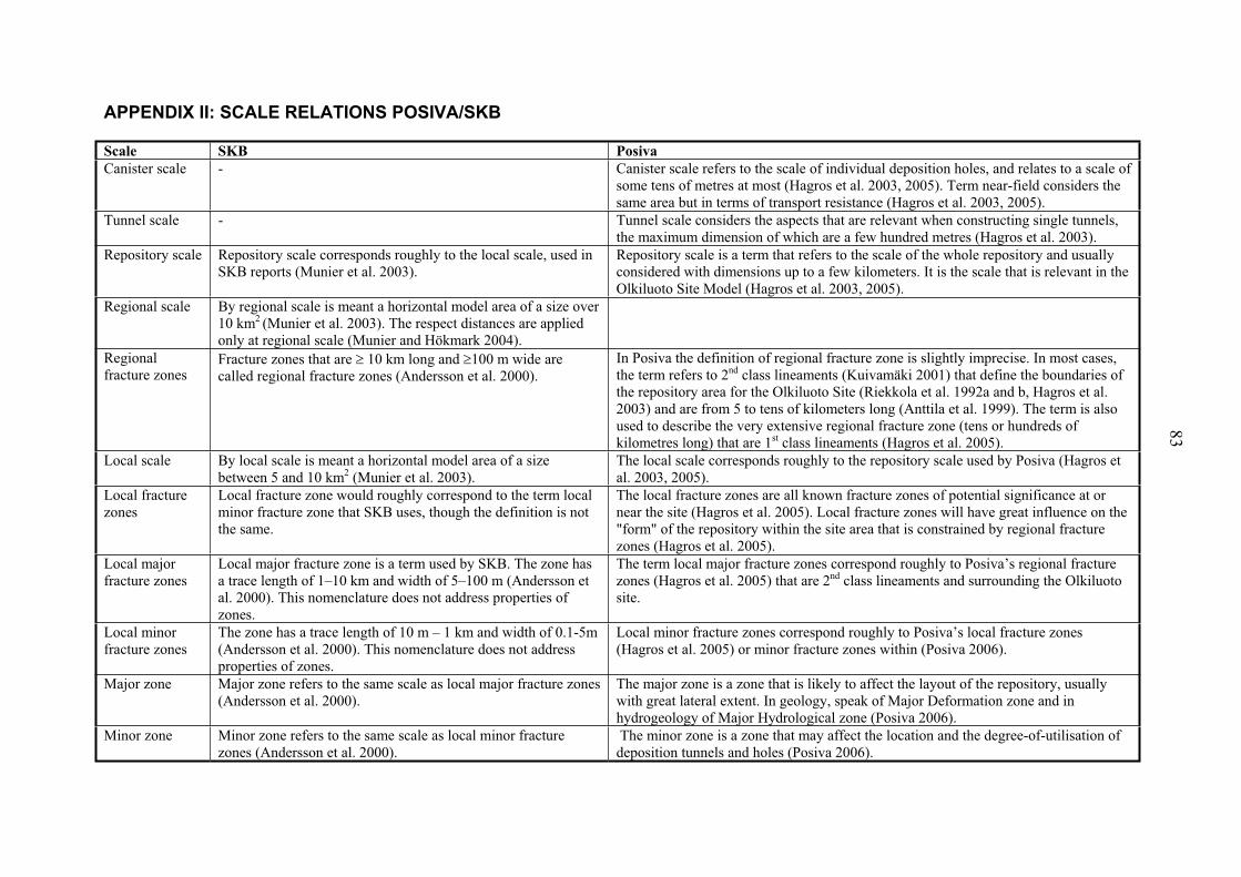
APPENDIX II: SCALE RELATIONS POSIVA/SKB
Scale SKB Posiva
Canister scale - Canister scale refers to the scale of individual deposition holes, and relates to a scale of some tens of metres at most (Hagros et al. 2003, 2005). Term near-field considers the same area but in terms of transport resistance (Hagros et al. 2003, 2005).
Tunnel scale - Tunnel scale considers the aspects that are relevant when constructing single tunnels, the maximum dimension of which are a few hundred metres (Hagros et al. 2003).
Repository scale Repository scale corresponds roughly to the local scale, used in SKB reports (Munier et al. 2003).
Repository scale is a term that refers to the scale of the whole repository and usually considered with dimensions up to a few kilometers. It is the scale that is relevant in the Olkiluoto Site Model (Hagros et al. 2003, 2005).
Regional scale By regional scale is meant a horizontal model area of a size over 10 km2 (Munier et al. 2003). The respect distances are applied only at regional scale (Munier and Hökmark 2004).
Regional fracture zones
Fracture zones that are 10 km long and 100 m wide are called regional fracture zones (Andersson et al. 2000).
In Posiva the definition of regional fracture zone is slightly imprecise. In most cases, the term refers to 2nd class lineaments (Kuivamäki 2001) that define the boundaries of the repository area for the Olkiluoto Site (Riekkola et al. 1992a and b, Hagros et al. 2003) and are from 5 to tens of kilometers long (Anttila et al. 1999). The term is also used to describe the very extensive regional fracture zone (tens or hundreds of kilometres long) that are 1st class lineaments (Hagros et al. 2005).
Local scale By local scale is meant a horizontal model area of a size between 5 and 10 km2 (Munier et al. 2003).
The local scale corresponds roughly to the repository scale used by Posiva (Hagros et al. 2003, 2005).
Local fracture zones
Local fracture zone would roughly correspond to the term local minor fracture zone that SKB uses, though the definition is not the same.
The local fracture zones are all known fracture zones of potential significance at or near the site (Hagros et al. 2005). Local fracture zones will have great influence on the "form" of the repository within the site area that is constrained by regional fracture zones (Hagros et al. 2005).
Local major fracture zones
Local major fracture zone is a term used by SKB. The zone has a trace length of 1–10 km and width of 5–100 m (Andersson et al. 2000). This nomenclature does not address properties of zones.
The term local major fracture zones correspond roughly to Posiva’s regional fracture zones (Hagros et al. 2005) that are 2nd class lineaments and surrounding the Olkiluoto site.
Local minor fracture zones
The zone has a trace length of 10 m – 1 km and width of 0.1-5m (Andersson et al. 2000). This nomenclature does not address properties of zones.
Local minor fracture zones correspond roughly to Posiva’s local fracture zones (Hagros et al. 2005) or minor fracture zones within (Posiva 2006).
Major zone Major zone refers to the same scale as local major fracture zones (Andersson et al. 2000).
The major zone is a zone that is likely to affect the layout of the repository, usually with great lateral extent. In geology, speak of Major Deformation zone and in hydrogeology of Major Hydrological zone (Posiva 2006).
Minor zone Minor zone refers to the same scale as local minor fracture zones (Andersson et al. 2000).
The minor zone is a zone that may affect the location and the degree-of-utilisation of deposition tunnels and holes (Posiva 2006).
83