terminus plug-in products user manual - janus rc terminal uses telit module ge865, firmware version...
TRANSCRIPT
Terminus Plug-In Products User Manual
Bulletin JA03-UMRevision P17Date 13 March 2014

Terminus Plug-In Hardware User Guide JA03-UM Page 2 Rev: P16 Date: 04/23/13© Copyright 2014 Janus Remote Communications Specifications subject to change without notice
All Rights Reserved See website for latest revision. Not intended for life support applications.
TABLE OF CONTENTSTABLE OF CONTENTS and DISCLAIMER ..........................................................................................................................2-3
1 APPLICABILITY TABLE ....................................................................................................................................................... 4
2 REFERENCES ..................................................................................................................................................................... 4
2.1 Telit Document List
2.2 Janus Document List
3 OVERVIEW ........................................................................................................................................................................... 5
3.1 Introduction .............................................................................................................................................................. 5
3.2 Preview .................................................................................................................................................................... 5
4 GSM865CF OVERVIEW ....................................................................................................................................................... 6
4.1 GSM Features ......................................................................................................................................................... 6
4.2 GSM Block Diagram ................................................................................................................................................ 6
5 CDMA864CF OVERVIEW .................................................................................................................................................... 7
5.1 CDMA Features ....................................................................................................................................................... 7
5.2 CDMA Block Diagram .............................................................................................................................................. 7
6 UMTS864CF OVERVIEW ..................................................................................................................................................... 8
6.1 UMTS Features ....................................................................................................................................................... 8
6.2 UMTS Block Diagram .............................................................................................................................................. 8
7 HSPA910CF OVERVIEW ..................................................................................................................................................... 9
7.1 HSPA+ Features ...................................................................................................................................................... 9
7.2 HSPA+ Block Diagram ............................................................................................................................................. 9
8 EVDO910CF OVERVIEW ................................................................................................................................................... 10
8.1 EV-DO Features .................................................................................................................................................... 10
8.2 EV-DO Block Diagram ........................................................................................................................................... 10
9 INTERFACES ................................................................................................................................................................11-23
9.1 Serial Interface ................................................................................................................................................. 11-12
9.2 Power Supply ......................................................................................................................................................... 12
9.3 Audio Interface ....................................................................................................................................................... 13
9.4 Plug-In Pin-Out ...................................................................................................................................................... 14
9.5 VRTC Details ......................................................................................................................................................... 15
9.6 GPIO Details ..................................................................................................................................................... 15-18
9.7 Internal Interfaces .................................................................................................................................................. 19
9.8 LED Status Indicators ............................................................................................................................................ 20
9.9 RF Interface ...................................................................................................................................................... 21-22
9.10 SIM Card Interface ................................................................................................................................................ 23
9.11 Header Interface Mounting Options ....................................................................................................................... 23
9.12 Screw Mounting ..................................................................................................................................................... 23
Terminus Plug-In Hardware User Guide JA03-UM Page 3 Rev: P16 Date: 04/23/13© Copyright 2014 Janus Remote Communications Specifications subject to change without notice
All Rights Reserved See website for latest revision. Not intended for life support applications.
TABLE OF CONTENTS continued10 GSM865CF TECHNICAL SPECIFICATIONS ..............................................................................................................24-31
10.1 Electrical Specifications ................................................................................................................................... 24-26
10.2 GSM Mechanical Specifications ........................................................................................................................... 27
10.3 MS20 GPS Specifications ..................................................................................................................................... 28
10.4 GSM865CF Getting Started ............................................................................................................................ 29-31
11 CDMA864CF TECHNICAL SPECIFICATIONS ...........................................................................................................32-40
11.1 Electrical Specifications ................................................................................................................................... 32-35
11.2 CDMA Mechanical Specifications ......................................................................................................................... 36
11.3 Setting Up a Terminal Emulator for use with the CDMA864CF Terminus ........................................................ 37-40
12 UMTS864CF TECHNICAL SPECIFICATIONS ............................................................................................................41-49
12.1 Electrical Specifications ................................................................................................................................... 41-44
12.2 UMTS Mechanical Specifications ......................................................................................................................... 45
12.3 Setting Up a Terminal Emulator for use with the UMTS864CF Terminus ........................................................ 46-49
13 HSPA910CF TECHNICAL SPECIFICATIONS.............................................................................................................50-58
13.1 Electrical Specifications ................................................................................................................................... 50-53
13.2 HSPA+ Mechanical Specifications ........................................................................................................................ 54
13.3 Setting Up a Terminal Emulator for use with the HSPA910CF Terminus ......................................................... 55-58
14 EVDO910CF TECHNICAL SPECIFICATIONS ............................................................................................................59-65
14.1 Electrical Specifications ................................................................................................................................... 59-61
14.2 EV-DO Mechanical Specifications ........................................................................................................................ 62
14.3 Setting Up a Terminal Emulator for use with the EVDO910CF Terminus ........................................................ 63-65
15 DESIGN CONSIDERATIONS ........................................................................................................................................... 66
15.1 GSM, CDMA, UMTS, HSPA+ and EV-DO Minimum Required Module Pin Connects .......................................... 66
15.2 Debug ................................................................................................................................................................... 66
APPENDICES ..................................................................................................................................................................67-68
Approvals ...................................................................................................................................................................... 67
Safety ........................................................................................................................................................................... 67
Antenna Care and Replacement .................................................................................................................................. 67
Abbreviations ................................................................................................................................................................ 67
Ordering Information ..................................................................................................................................................... 68
Revision History ............................................................................................................................................................ 68
DISCLAIMERThe information contained in this document is the proprietary information of Connor-Winfield Corporation and its affiliates (Janus Remote Communication). The contents are confidential and any disclosure to
persons other than the officers, employees, agents or subcontractors of the owner or licensee of this document, without the prior written consent of Connor-Winfield, is strictly prohibited. Connor-Winfield makes every effort to ensure the quality of the information it makes available. Notwithstanding the foregoing, Connor-Winfield does not make any warranty as to the information contained herein, and does not accept any liability for any injury, loss or damage of any kind incurred by use of or reliance upon the information. Connor-Winfield disclaims any and all responsibility for the application of the devices characterized in this document, and notes that the application of the device must comply with the safety standards of the applicable country, and where applicable, with the relevant wiring rules. Connor-Winfield reserves the right to make modifications, additions and deletions to this document due to typographical errors, inaccurate information, or improvements to programs and/or equipment at any time and without notice. Such changes will, nevertheless be incorporated into new editions of this application note.
All rights reserved 2012 Connor-Winfield Corporation

Terminus Plug-In Hardware User Guide JA03-UM Page 4 Rev: P16 Date: 04/23/13© Copyright 2014 Janus Remote Communications Specifications subject to change without notice
All Rights Reserved See website for latest revision. Not intended for life support applications.
1 APPLICABILITY TABLEProduct Part NumberGSM865CF (with GPS) v1.1 GSM865CF (without GPS) v2.0 CDMA864CF (Sprint Certified) v2.0CDMA864CF (Verizon Certified) v3.0 UMTS864CF v1.0HSPA910CF v1.0EVDO910CF v3.0
2 REFERENCES2.1 Telit Document List
GSM865CF V1.1 (AT&T Certified)Our terminal uses Telit module GE865, Firmware version 10.00.003 Please refer to Telit’s website at www.telit.com for the latest information on the GSM GE865 module.Telit_GE865_Hardware_User_GuideTelit_Modules_Software_User_GuideTelit_AT_Commands_Reference_Guide – Issue #9
Please go to www.janus-rc.com to download the AT Command Reference Guide
CDMA864CF V2.00 (Sprint Certified)Our terminal uses Telit module CC864-DUAL, firmware version 09.01.003 or 09.01.004 Please refer to Telit’s website at www.telit.com for the latest information on the CDMA CC864-DUAL module.Telit_CC864-DUAL_Hardware_User_GuideTelit_CC864-DUAL_Software_User_GuideTelit_CC864-DUAL_AT_Commands_Reference_Guide – Issue #2
Available at www.janus-rc.com
CDMA864CF V3.00 (Verizon Certified)Our terminal uses Telit module CC864-DUAL, firmware version 09.01.023-B021 Please refer to Telit’s website at www.telit.com for the latest information on the CDMA CC864-DUAL module.Telit_CC864-DUAL_Hardware_User_GuideTelit_CC864-DUAL_Software_User_GuideTelit_CC864-DUAL_AT_Commands_Reference_Guide – Issue #4
Available at www.janus-rc.com
UMTS864CFOur terminal uses Telit module UC864-G, firmware version 08.01.127 or 08.01.147 Please refer to Telit’s website at www.telit.com for the latest information on the UMTS UC864-G module.Telit_UC864_Hardware_User_GuideTelit_UC864_Software_User_GuideTelit_UC864_AT_Commands_Reference_Guide – Issue #7
Available at www.janus-rc.com
HSPA910CFOur terminal uses Telit module HE910. Please refer to Telit’s website at www.telit.com for the latest information on the HSPA+ HE910 Module.Telit_HE910_Hardware_User_GuideTelit_HE910_Software_User_GuideTelit_HE910_AT_Commands_Reference_GuideTelit_HE910_DVI_App_Note
EVDO910CFOur terminal uses Telit module DE910. Please refer to Telit’s website at www.telit.com for the latest information on the EV-DO DE910 Module.Telit_DE910_Hardware_User_GuideTelit_DE910_Software_User_GuideTelit_DE910_AT_Commands_Reference_GuideTelit_HE910_DVI_App_Note
2.2 Janus Document ListPlease refer to the NavSync’s website, www.navsync.com, for the latest information on the MS20.MS20 Documentation

Terminus Plug-In Hardware User Guide JA03-UM Page 5 Rev: P16 Date: 04/23/13© Copyright 2014 Janus Remote Communications Specifications subject to change without notice
All Rights Reserved See website for latest revision. Not intended for life support applications.
3 OVERVIEW3.1 Introduction
The User Manual for the Plug-In Terminus devices is intended to illustrate how users can integrate and implement the features of each communication version of the device. The common factors are explained in detail, as well as special considerations and diagrams for each module. The module differences are highlighted in this manual for design considerations for future model placement.
3.2 PreviewThe Terminus GSM865CF, CDMA864CF, UMTS864CF, HSPA910CF and EVDO910CF are self-contained, multi-band, globally capable, M2M communication devices designed to provide a comprehensive solution to application problems for our M2M customers. They utilize the proven technology of Telit’s GE865, UC864-G, CC864-DUAL, HE910 and DE910 modules, respectively, for their core communications engines. NavSync’s MS20 module adds the flexibility of GPS to the GSM865CF only.
3.2.1 Functional DescriptionPlug-In Module Differences
GPS Functionality• CDMA864CF has an internal GPS solution available via Telit AT command interface • UMTS864CF has an internal GPS solution available via Telit AT command interface • GSM865CF has an optional stand alone NavSync MS20 12 channel GPS receiver that is not accessible via Telit AT
command port.• HSPA910CF has an internal GPS solution available via Telit AT command interface• EVDO910CF has an internal GPS solution available via Telit AT command interface
Physical Dimensions• Length and width of devices are equal• Heights of different devices will vary
Cellular• GSM/GPRS• EV-DO/CDMA/1xRTT (Sprint and Verizon certified versions)• HSPA/UMTS/EDGE/GPRS/GSM
AT commands may vary between different cellular technologies.
USB• EVDO, CDMA, & UMTS (FS USB Device Interface)• HSPA+ (HS USB Device Interface)• GSM (not available)
(TOP VIEW)
.047 DIA (49)
.100 TYP
1.100
.100 TYP
.050
2.400
2.300
PIN 1 PIN 25
PIN 26PIN 49
Terminus Plug-In Hardware User Guide JA03-UM Page 6 Rev: P16 Date: 04/23/13© Copyright 2014 Janus Remote Communications Specifications subject to change without notice
All Rights Reserved See website for latest revision. Not intended for life support applications.
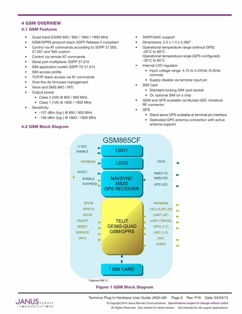
4 GSM OVERVIEW4.1 GSM Features
• Quad-band EGSM 850 / 900 / 1800 / 1900 MHz• GSM/GPRS protocol stack 3GPP Release 4 compliant• Control via AT commands according to 3GPP 27.005,
27.007 and Telit custom• Control via remote AT commands• Serial port multiplexer 3GPP 27.010• SIM application toolkit 3GPP TS 51.014• SIM access profile• TCP/IP stack access via AT commands• Over-the-Air firmware management• Voice and SMS (MO / MT)• Output power
• Class 4 (2W) @ 850 / 900 MHz• Class 1 (1W) @ 1800 / 1900 MHz
• Sensitivity:• -107 dBm (typ.) @ 850 / 900 MHz• -106 dBm (typ.) @ 1800 / 1900 MHz
• DARP/SAIC support• Dimensions: 2.5 x 1.4 x 0.365”• Operational temperature range (without GPS):
-40°C to 80°C Operational temperature range (GPS configured): -30°C to 65°C
• Internal LDO regulator• Input voltage range: 4.75 to 5.25Vdc (5.0Vdc
nominal)• Supply disable via terminal input pin
• SIM Card• Standard locking SIM card socket• Or, optional SIM on a chip
• GSM and GPS available via Murata GSC miniature RF connector
• GPS• Stand alone GPS available at terminal pin interface• Dedicated GPS antenna connection with active
antenna support4.2 GSM Block Diagram
TELITGE865-QUADGSM/GPRS
TELITGE865-QUADGSM/GPRS
NAVSYNCMS20
GPS RECEIVER
NAVSYNCMS20
GPS RECEIVER
* SIM CARD* SIM CARD
LDO1LDO1
VAUX
GSM865CF
NMEA TX
NMEA RX
UART (AT)
UART (TRACE)
GPIO (1-7)
ADC (1-2)
DAC
5 VDC
ENABLE
RESET
PWRMON
CELLULAR LED
GPIO8
ENABLE
GPIO10
GPIO9
SUSPEND
RESET
ON/OFF
SERVICE
VRTC
GPS LED
AUDIO
* Optional SIM I.C.
LDO2LDO2PWRMON
Figure 1 GSM Block Diagram
Terminus Plug-In Hardware User Guide JA03-UM Page 7 Rev: P16 Date: 04/23/13© Copyright 2014 Janus Remote Communications Specifications subject to change without notice
All Rights Reserved See website for latest revision. Not intended for life support applications.
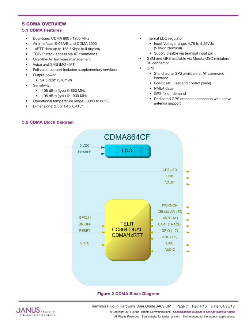
5 CDMA OVERVIEW5.1 CDMA Features
• Dual-band CDMA 800 / 1900 MHz• Air interface IS-95A/B and CDMA 2000• 1xRTT data up to 153.6Kbps (full duplex)• TCP/IP stack access via AT commands• Over-the-Air firmware management• Voice and SMS (MO / MT)• Full voice support includes supplementary services• Output power
• 24.3 dBm (270mW)• Sensitivity:
• -108 dBm (typ.) @ 800 MHz• -108 dBm (typ.) @ 1900 MHz
• Operational temperature range: -30°C to 80°C• Dimensions: 2.5 x 1.4 x 0.415”
• Internal LDO regulator• Input Voltage range: 4.75 to 5.25Vdc
(5.0Vdc Nominal)• Supply disable via terminal input pin
• GSM and GPS available via Murata GSC miniature RF connector
• GPS• Stand alone GPS available at AT command
interface• GpsOne® (user and control plane)• NMEA data• GPS fix on demand• Dedicated GPS antenna connection with active
antenna support
5.2 CDMA Block Diagram
Figure 2 CDMA Block Diagram
TELITCC864-DUALCDMA/1xRTT
LDO
CDMA864CF
GPS LED
USB
UART (AT)
UART (TRACE)
GPIO (1-7)
ADC (1-2)
DAC
5 VDC
ENABLE
PWRMON
CELLULAR LED
GPIO21
RESET
ON/OFF
VRTC
VAUX
AUDIO
Terminus Plug-In Hardware User Guide JA03-UM Page 8 Rev: P16 Date: 04/23/13© Copyright 2014 Janus Remote Communications Specifications subject to change without notice
All Rights Reserved See website for latest revision. Not intended for life support applications.
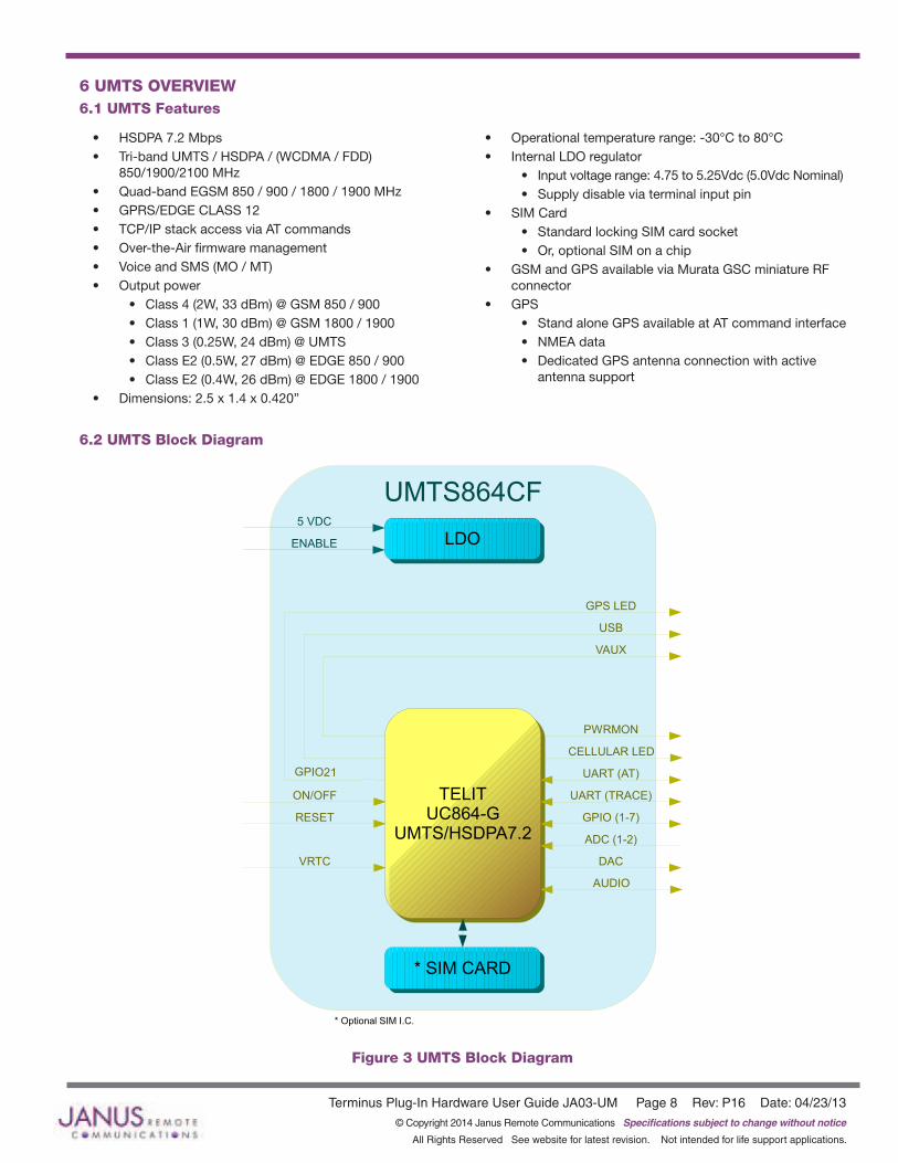
• HSDPA 7.2 Mbps• Tri-band UMTS / HSDPA / (WCDMA / FDD)
850/1900/2100 MHz• Quad-band EGSM 850 / 900 / 1800 / 1900 MHz• GPRS/EDGE CLASS 12• TCP/IP stack access via AT commands• Over-the-Air firmware management• Voice and SMS (MO / MT)• Output power
• Class 4 (2W, 33 dBm) @ GSM 850 / 900• Class 1 (1W, 30 dBm) @ GSM 1800 / 1900• Class 3 (0.25W, 24 dBm) @ UMTS• Class E2 (0.5W, 27 dBm) @ EDGE 850 / 900• Class E2 (0.4W, 26 dBm) @ EDGE 1800 / 1900
• Dimensions: 2.5 x 1.4 x 0.420”
• Operational temperature range: -30°C to 80°C• Internal LDO regulator
• Input voltage range: 4.75 to 5.25Vdc (5.0Vdc Nominal)• Supply disable via terminal input pin
• SIM Card• Standard locking SIM card socket• Or, optional SIM on a chip
• GSM and GPS available via Murata GSC miniature RF connector
• GPS• Stand alone GPS available at AT command interface• NMEA data• Dedicated GPS antenna connection with active
antenna support
6.2 UMTS Block Diagram
6 UMTS OVERVIEW6.1 UMTS Features
TELITUC864-G
UMTS/HSDPA7.2
* SIM CARD
LDO
UMTS864CF
GPS LED
USB
UART (AT)
UART (TRACE)
GPIO (1-7)
ADC (1-2)
DAC
5 VDC
ENABLE
PWRMON
CELLULAR LED
GPIO21
RESET
ON/OFF
VRTC
VAUX
AUDIO
* Optional SIM I.C.
Figure 3 UMTS Block Diagram
Terminus Plug-In Hardware User Guide JA03-UM Page 9 Rev: P16 Date: 04/23/13© Copyright 2014 Janus Remote Communications Specifications subject to change without notice
All Rights Reserved See website for latest revision. Not intended for life support applications.
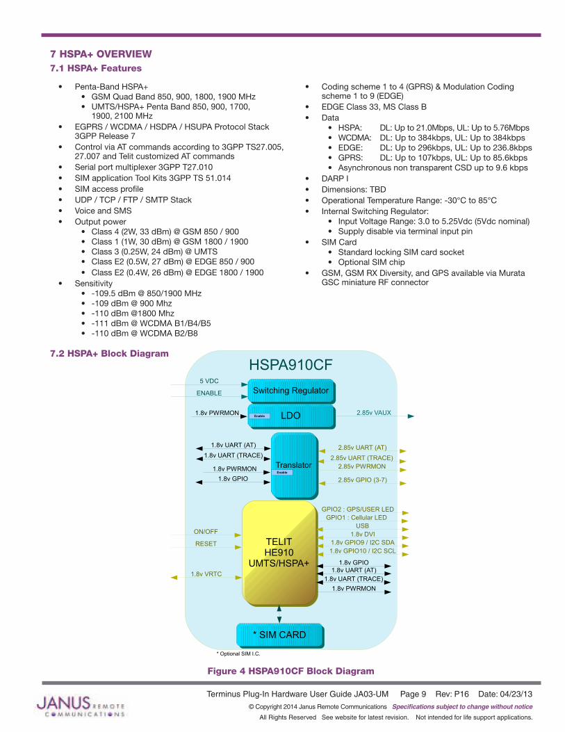
• Penta-Band HSPA+• GSM Quad Band 850, 900, 1800, 1900 MHz• UMTS/HSPA+ Penta Band 850, 900, 1700,
1900, 2100 MHz• EGPRS / WCDMA / HSDPA / HSUPA Protocol Stack
3GPP Release 7• Control via AT commands according to 3GPP TS27.005,
27.007 and Telit customized AT commands• Serial port multiplexer 3GPP T27.010• SIM application Tool Kits 3GPP TS 51.014• SIM access profile• UDP / TCP / FTP / SMTP Stack• Voice and SMS• Output power
• Class 4 (2W, 33 dBm) @ GSM 850 / 900• Class 1 (1W, 30 dBm) @ GSM 1800 / 1900• Class 3 (0.25W, 24 dBm) @ UMTS• Class E2 (0.5W, 27 dBm) @ EDGE 850 / 900• Class E2 (0.4W, 26 dBm) @ EDGE 1800 / 1900
• Sensitivity• -109.5 dBm @ 850/1900 MHz• -109 dBm @ 900 Mhz• -110 dBm @1800 Mhz• -111 dBm @ WCDMA B1/B4/B5• -110 dBm @ WCDMA B2/B8
• Coding scheme 1 to 4 (GPRS) & Modulation Coding scheme 1 to 9 (EDGE)
• EDGE Class 33, MS Class B• Data
• HSPA: DL: Up to 21.0Mbps, UL: Up to 5.76Mbps• WCDMA: DL: Up to 384kbps, UL: Up to 384kbps• EDGE: DL: Up to 296kbps, UL: Up to 236.8kbps• GPRS: DL: Up to 107kbps, UL: Up to 85.6kbps• Asynchronous non transparent CSD up to 9.6 kbps
• DARP I• Dimensions: TBD• Operational Temperature Range: -30°C to 85°C• Internal Switching Regulator:
• Input Voltage Range: 3.0 to 5.25Vdc (5Vdc nominal)• Supply disable via terminal input pin
• SIM Card• Standard locking SIM card socket• Optional SIM chip
• GSM, GSM RX Diversity, and GPS available via Murata GSC miniature RF connector
7.2 HSPA+ Block Diagram
7 HSPA+ OVERVIEW7.1 HSPA+ Features
Figure 4 HSPA910CF Block Diagram
TELITHE910
UMTS/HSPA+
* SIM CARD
Switching Regulator
HSPA910CF
GPIO2 : GPS/USER LED
USB
2.85v UART (AT)
2.85v UART (TRACE)
2.85v GPIO (3-7)
5 VDC
ENABLE
1.8v PWRMON
RESET
ON/OFF
1.8v VRTC
GPIO1 : Cellular LED
1.8v DVI
* Optional SIM I.C.
LDO 2.85v VAUX
Translator
1.8v UART (AT)
1.8v UART (TRACE)
1.8v PWRMON 2.85v PWRMON
1.8v UART (AT)
1.8v UART (TRACE)
1.8v PWRMONEnable
Enable
1.8v GPIO
1.8v GPIO
1.8v GPIO9 / I2C SDA
1.8v GPIO10 / I2C SCL
Terminus Plug-In Hardware User Guide JA03-UM Page 10 Rev: P16 Date: 04/23/13© Copyright 2014 Janus Remote Communications Specifications subject to change without notice
All Rights Reserved See website for latest revision. Not intended for life support applications.
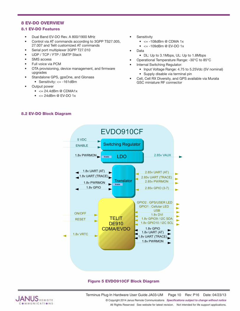
8 EV-DO OVERVIEW8.1 EV-DO Features
• Dual Band EV-DO Rev. A 800/1900 MHz• Control via AT commands according to 3GPP TS27.005,
27.007 and Telit customized AT commands• Serial port multiplexer 3GPP T27.010• UDP / TCP / FTP / SMTP Stack• SMS access• Full voice via PCM• OTA provisioning, device management, and firmware
upgrades• Standalone GPS, gpsOne, and Glonass
• Sensitivity: <= -161dBm• Output power
• <= 24.4dBm @ CDMA1x• <= 24dBm @ EV-DO 1x
• Sensitivity• <= -108dBm @ CDMA 1x• <= -109dBm @ EV-DO 1x
• Data• DL: Up to 3.1Mbps, UL: Up to 1.8Mbps
• Operational Temperature Range: -30°C to 85°C• Internal Switching Regulator:
• Input Voltage Range: 4.75 to 5.25Vdc (5V nominal)• Supply disable via terminal pin
• Cell, Cell RX Diversity, and GPS available via Murata GSC miniature RF connector
8.2 EV-DO Block Diagram
TELITDE910
CDMA/EVDO
Switching Regulator
EVDO910CF
GPIO2 : GPS/USER LED
USB
2.85v UART (AT)
2.85v UART (TRACE)
2.85v GPIO (3-7)
5 VDC
ENABLE
1.8v PWRMON
RESET
ON/OFF
1.8v VRTC
GPIO1 : Cellular LED
1.8v DVI
LDO 2.85v VAUX
Translator
1.8v UART (AT)
1.8v UART (TRACE)
1.8v PWRMON 2.85v PWRMON
1.8v UART (AT)
1.8v UART (TRACE)
1.8v PWRMONEnable
Enable
1.8v GPIO
1.8v GPIO
1.8v GPIO9 / I2C SDA
1.8v GPIO10 / I2C SCL
Figure 5 EVDO910CF Block Diagram

Terminus Plug-In Hardware User Guide JA03-UM Page 11 Rev: P16 Date: 04/23/13© Copyright 2014 Janus Remote Communications Specifications subject to change without notice
All Rights Reserved See website for latest revision. Not intended for life support applications.
Figure 6 UART Level Translation Example
9 INTERFACES9.1 Serial Interface
9.1.1 UART Serial Port
The serial interface is a CMOS level UART. Default Communications settings for this port are as follows:
• Baud Rate: 115.2 kbps
• Bits: 8
• Stop Bits: 1
• Parity: None
• Hardware Handshaking: Yes
When not using the baud rate default, the GSM865CF supports autobaud while the CDMA864CF, UMTS864CF,
HSPA910CF and EVDO910CF do not. Please refer to the individual modem’s Getting Started section for details. Note:IfyouarenotusingHardwareHandshaking,pleasenotethatRTSmustbeconnectedtoGROUNDforpropercommunications
whereflowcontrolisunused.
9.1.1.1 UART Level TranslationThe electrical limits for the UART are listed in the individual modem sections. Please be aware of these limits, as operating outside of them may damage the unit. If the limits must be exceeded, level translation can be used. An example of basic translation for RXD/TXD only is found below.
Although an external source for the level translation can be used, VAUX can be used as the reference instead. However, since the CDMA864CF and UMTS864CF require AT commands to control VAUX, PWRMON may be used as an enable to the external reference. Do not use PWRMON directly as the reference.
9.1.2 USB Port
UMTS864CF, CDMA864CF, HSPA910CF & EVDO910CF include an integrated universal serial bus (USB)
transceiver, compliant with USB 2.0 specifications. The UMTS/CDMA864CF are USB full speed devices
(12Mb/s), while the HSPA910CF and EVDO910CF are a high speed device (480Mb/s). High data rates for
the USB enabled modems are only available over the USB interface. In order for proper power-up of the
UMTS864CF, CDMA864CF, HSPA910CF and the EVDO910CF, the USB_VBUS line MUST be disconnected until
the unit is otherwise fully powered and on. If the USB_VBUS line is attached and powered before the main power
is brought up and the module turned on, power sequencing issues may occur.Note:YoumustimplementtheUSBinterfaceinordertolocallyupdateradiofirmwareforCDMAandUMTSapplications.TheGSM865CFdoesnothaveUSBportavailable.
Terminus Plug-In Hardware User Guide JA03-UM Page 12 Rev: P16 Date: 04/23/13© Copyright 2014 Janus Remote Communications Specifications subject to change without notice
All Rights Reserved See website for latest revision. Not intended for life support applications.
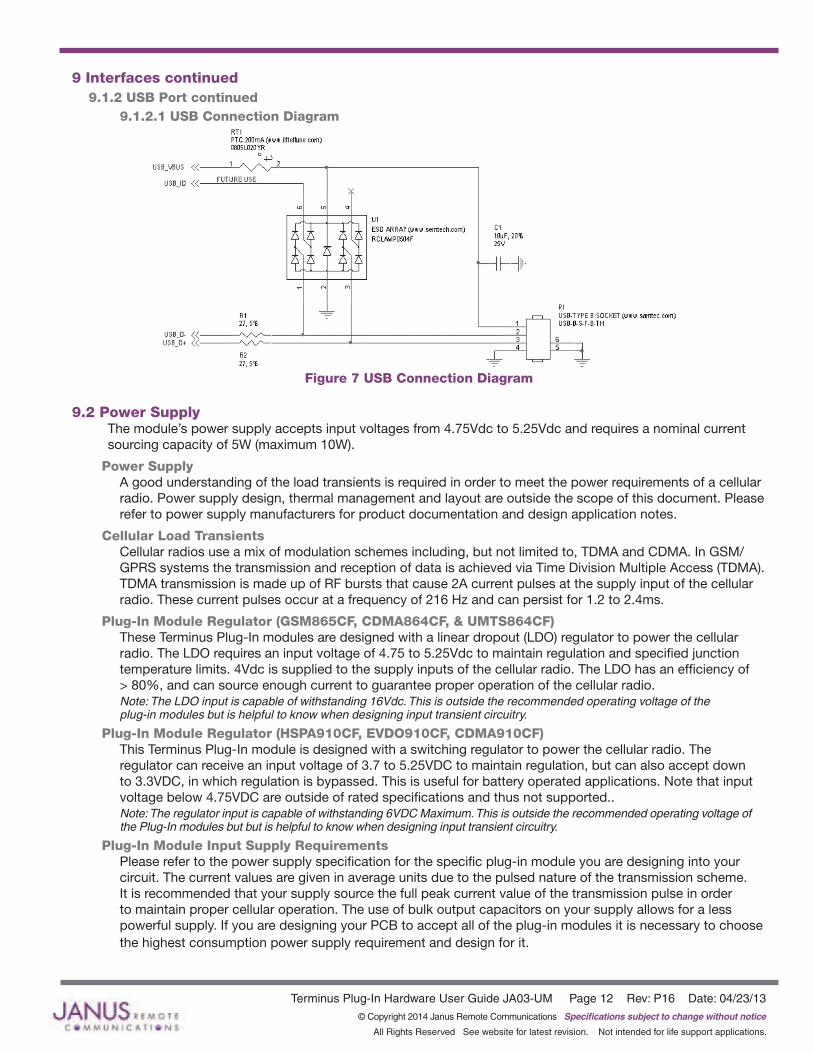
Figure 7 USB Connection Diagram
9 Interfaces continued9.1.2 USB Port continued 9.1.2.1 USB Connection Diagram
9.2 Power SupplyThe module’s power supply accepts input voltages from 4.75Vdc to 5.25Vdc and requires a nominal current sourcing capacity of 5W (maximum 10W).
Power SupplyA good understanding of the load transients is required in order to meet the power requirements of a cellular radio. Power supply design, thermal management and layout are outside the scope of this document. Please refer to power supply manufacturers for product documentation and design application notes.
Cellular Load TransientsCellular radios use a mix of modulation schemes including, but not limited to, TDMA and CDMA. In GSM/GPRS systems the transmission and reception of data is achieved via Time Division Multiple Access (TDMA). TDMA transmission is made up of RF bursts that cause 2A current pulses at the supply input of the cellular radio. These current pulses occur at a frequency of 216 Hz and can persist for 1.2 to 2.4ms.
Plug-In Module Regulator (GSM865CF, CDMA864CF, & UMTS864CF)These Terminus Plug-In modules are designed with a linear dropout (LDO) regulator to power the cellular radio. The LDO requires an input voltage of 4.75 to 5.25Vdc to maintain regulation and specified junction temperature limits. 4Vdc is supplied to the supply inputs of the cellular radio. The LDO has an efficiency of > 80%, and can source enough current to guarantee proper operation of the cellular radio.Note: The LDO input is capable of withstanding 16Vdc. This is outside the recommended operating voltage of the plug-in modules but is helpful to know when designing input transient circuitry.
Plug-In Module Regulator (HSPA910CF, EVDO910CF, CDMA910CF)This Terminus Plug-In module is designed with a switching regulator to power the cellular radio. The regulator can receive an input voltage of 3.7 to 5.25VDC to maintain regulation, but can also accept down to 3.3VDC, in which regulation is bypassed. This is useful for battery operated applications. Note that input voltage below 4.75VDC are outside of rated specifications and thus not supported..Note: The regulator input is capable of withstanding 6VDC Maximum. This is outside the recommended operating voltage of the Plug-In modules but but is helpful to know when designing input transient circuitry.
Plug-In Module Input Supply Requirements Please refer to the power supply specification for the specific plug-in module you are designing into your circuit. The current values are given in average units due to the pulsed nature of the transmission scheme. It is recommended that your supply source the full peak current value of the transmission pulse in order to maintain proper cellular operation. The use of bulk output capacitors on your supply allows for a less powerful supply. If you are designing your PCB to accept all of the plug-in modules it is necessary to choose the highest consumption power supply requirement and design for it.
Terminus Plug-In Hardware User Guide JA03-UM Page 13 Rev: P16 Date: 04/23/13© Copyright 2014 Janus Remote Communications Specifications subject to change without notice
All Rights Reserved See website for latest revision. Not intended for life support applications.
Figure 8 Analog Audio Circuit Diagram
DTE HSPA910CFMAX9867
Codec
BitClock
Word Alignment
Data Transmitted
Data Received
SDA
SCL
G
PIO
9
GP
IO10
Analog Out
Analog In
Figure 9 DVI Block Diagram
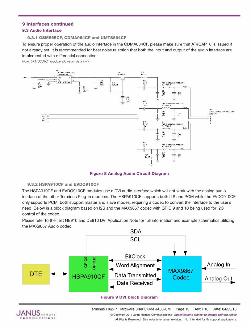
9 Interfaces continued9.3 Audio Interface
9.3.1 GSM865CF, CDMA964CF and UMTS864CF
To ensure proper operation of the audio interface in the CDMA864CF, please make sure that AT#CAP=0 is issued if not already set. It is recommended for best noise rejection that both the input and output of the audio interface are implemented with differential connection.Note:UMTS864CFmoduleallowsfordataonly.
9.3.2 HSPA910CF and EVDO910CF
The HSPA910CF and EVDO910CF modules use a DVI audio interface which will not work with the analog audio inerface of the other Terminus Plug-In modems. The HSPA910CF supports both I2S and PCM while the EVDO910CF only supports PCM, both support master and slave modes, requiring a codec to convert the interface to the user’s need. Below is a block diagram based on I2S and the MAX9867 codec with GPIO 9 and 10 being used for I2C control of the codec.
Please refer to the Telit HE910 and DE910 DVI Application Note for full information and example schematics utilizing the MAX9867 Audio codec.
Terminus Plug-In Hardware User Guide JA03-UM Page 14 Rev: P16 Date: 04/23/13© Copyright 2014 Janus Remote Communications Specifications subject to change without notice
All Rights Reserved See website for latest revision. Not intended for life support applications.
9 Interfaces continued
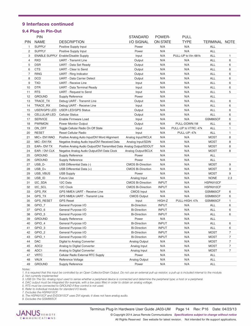
9.4 Plug-In Pin-Out PIN STANDARD POWER- PULL PIN NAME DESCRIPTION I/O SIGNAL ON STATE TYPE TERMINAL NOTE 1 SUPPLY Positive Supply Input Power N/A N/A ALL
2 SUPPLY Positive Supply Input Power N/A N/A ALL
3 ENABLE SUPPLY Enable/Disable Supply Input N/A PULL-UP to Vin: 681k ALL 1
4 RXD UART - Transmit Line Output N/A N/A ALL 6
5 DSR UART - Data Set Ready Output N/A N/A ALL 6
6 CTS UART - Clear to Send Output N/A N/A ALL 6
7 RING UART - Ring Indicator Output N/A N/A ALL 6
8 DCD UART - Data Carrier Detect Output N/A N/A ALL 6
9 TXD UART - Receive Line Input N/A N/A ALL 6
10 DTR UART - Data Terminal Ready Input N/A N/A ALL 6
11 RTS UART - Request to Send Input N/A N/A ALL 5
12 GROUND Supply Reference Power N/A N/A ALL
13 TRACE_TX Debug UART - Transmit Line Output N/A N/A ALL 6
14 TRACE_RX Debug UART - Receive Line Input N/A N/A ALL 6
15 USER/GPS LED USER LED/GPS Status Output N/A N/A ALL 6
16 CELLULAR LED Cellular Status Output N/A N/A ALL 6
17 SERVICE Enable Firmware Load Input N/A N/A GSM865CF 6
18 PWRMON Power Monitor Output Output N/A PULL-DOWN:1M ALL 6
19 ON_OFF Toggle Cellular Radio On Off State Input N/A PULL-UP to VTRC: 47k ALL 1
20 RESET Reset Cellular Radio Input N/A PULL-UP: 47k ALL 1
21 MIC+ /DVI WAO Positive Analog Autio Input/DVI Word Alignment Analog Input/WCLK N/A N/A MOST 8
22 MIC- /DVI RX Negative Analog Audio Input/DVI Received Data Analog Input/SDIN N/A N/A MOST 8
23 EAR+ /DVI TX Positive Analog Audio Output/DVI Transmitted Data Analog Output/SDOUT N/A N/A MOST 8
24 EAR- / DVI CLK Negative Analog Audio Output/DVI Data Clock Analog Output/BCLK N/A N/A MOST 8
25 GROUND Supply Reference Power N/A N/A ALL
26 GROUND Supply Reference Power N/A N/A ALL
27 USB_D- USB Differential Data (-) CMOS Bi-Direction N/A N/A MOST 9
28 USB_D+ USB Differential Data (+) CMOS Bi-Direction N/A N/A MOST 9
29 USB_VBUS USB Supply Power N/A N/A MOST 9
30 USB_ID Future Use Analog Input N/A N/A NONE 2,3
31 I2C_SDA 12C Data CMOS Bi-Direction INPUT N/A HSPA910CF
32 I2C_SCL 12C Clock CMOS Bi-Direction INPUT N/A HSPA910CF
33 GPS_RX GPS NMEA UART - Receive Line CMOS Input N/A N/A GSM865CF 6
34 GPS_TX GPS NMEA UART - Transmit Line CMOS Output N/A N/A GSM865CF 6
35 GPS_RESET GPS Reset Input HIGH-Z PULL-HIGH: 47k GSM865CF 1
36 GPIO_7 General Purpose I/O Bi-Direction INPUT N/A ALL 6
37 GPIO_6 General Purpose I/O Bi-Direction INPUT N/A ALL 6
38 GPIO_5 General Purpose I/O Bi-Direction INPUT N/A ALL 6
39 GROUND Supply Reference Power N/A N/A ALL
40 GPIO_4 General Purpose I/O Bi-Direction INPUT N/A ALL 6
41 GPIO_3 General Purpose I/O Bi-Direction INPUT N/A ALL 6
42 GPIO_2 General Purpose I/O Bi-Direction INPUT N/A MOST 7
43 GPIO_1 General Purpose I/O Bi-Direction INPUT N/A MOST 7
44 DAC Digital to Analog Converter Analog Output N/A N/A MOST 7
45 ADC2 Analog to Digital Converter Analog Input N/A N/A MOST 7
46 ADC1 Analog to Digital Converter Analog Input N/A N/A MOST 7
47 VRTC Cellular Radio External RTC Supply Power N/A N/A ALL
48 VAUX Reference Voltage Analog Output N/A N/A ALL
49 GROUND Supply Reference Power N/A N/A ALL
Notes: 1.ItisrequiredthatthisinputbecontrolledbyanOpenCollector/DrainOutput.Donotuseanexternalpull-upresistor;apull-upisincludedinternaltothemodule.2.Notcurrentlyimplemented3.USBOnTheGo:Analoginputusedtosensewhetheraperipheraldeviceisconnectedanddeterminetheperipheraltype;ahostoraperipheral.4.DACoutputmustbeintegrated(forexample,withalowpassfilter)inordertoobtainananalogvoltage.5.RTSmustbeconnectedtoGROUNDifflowcontrolisnotused.6.RefertoindividualmodulesforstandardI/Olevels.7.ExcludestheHSPA910CF.8.TheHSPA910CFandEVDO910CFusesDVIsignals;itdoesnothaveanalogaudio.9.ExcludestheGSM865CF.

Terminus Plug-In Hardware User Guide JA03-UM Page 15 Rev: P16 Date: 04/23/13© Copyright 2014 Janus Remote Communications Specifications subject to change without notice
All Rights Reserved See website for latest revision. Not intended for life support applications.
9 Interfaces continued9.5 VRTC DetailsThe VRTC pin brings out the real time clock supply, which is separate from the rest of the part. This allows only the RTC to be ON when all other parts of the device are OFF. A backup capacitor can be added to this pin to increase RTC autonomy while powering the device from a battery. The CDMA910CF cannot take advantage of the VRTC functionality.No devices should be powered from this pin.
Equations:C = 3600 * [(Btime * IRTC)/(VRTC - VRTCmin)]Btime = [C * (VRTC - VRTCmin)/(IRTC * 3600)]
Where:VRTC – The Starting voltage of the capacitor (Volt)VRTCmin – The minimum voltage acceptable for the RTC circuit. (Volt)IRTC (Ampere) – The current consumption of the RTC circuitry when VBATT = 0Btime - Backup Time (Hours)C = Capacitor value (Farads)
Values for the GSM865CF/CDMA864CF/UMTS864CFVRTC = 2.05v NominalVRTC minimum input voltage to function = 1.1vIRTC = 10uA nominal
Values for the HSPA910CFVRTC = 1.8v NominalVRTC minimum input voltage to function = 1.1vIRTC = 2uA nominal
Values for the EVDO910CFVRTC = 3.1v NominalVRTC minimum input voltage to function = 2.0vIRTC = 1.1uA nominal
Values for the CDMA910CFVRTC = N/AVRTC minimum input voltage to function = N/AIRTC = N/A
For Example, using the HSPA910CF numbers:Btime = 96 hours (4 days)
C = 1.0F
9.6 GPIO DetailsTerminus GPIO are configurable as input, output, and special function. Configuration is controlled by the customer specific application via AT commands sent on the UART/USB interface. The following table describes GPIO configuration options. Please note that these alternate functions are not supported by the HSPA910CF, EVDO910CF, and CDMA910CF.
GPIO Configuration Alternate Function ON_OFF State 1 Input / Output pull-up 2 Input / Output Jamming detect output pull-up 3 Input / Output pull-down 4 Input / Output RF transmission control pull-down 5 Input / Output RFTX monitor output pull-down 6 Input / Output Alarm output pull-up 7 Input / Output Buzzer output pull-down

Terminus Plug-In Hardware User Guide JA03-UM Page 16 Rev: P16 Date: 04/23/13© Copyright 2014 Janus Remote Communications Specifications subject to change without notice
All Rights Reserved See website for latest revision. Not intended for life support applications.
9 Interfaces continued9.6 GPIO Details continued
9.6.1 Using a GPIO Pad as INPUTThe GPIO pads, when used as inputs, can be connected to a digital output of another device and report its status, provided this device has interface levels compatible with the Voltage levels of the GPIO of the module.
9.6.2 Using a GPIO Pad as OUTPUTThe GPIO pads, when used as outputs, can drive CMOS digital devices or compatible hardware. When set as outputs, the pads have a push-pull output.
9.6.3 Using the Alarm Output GPIO6When configured as alarm output, the GPIO6 pad is controlled by the module, rising when the alarm starts and falling after the issue of a dedicated AT command. This output can be used to power up the module controlling micro-controller or application at the alarm time. This enables you to program a timely system wake-up to achieve periodic actions and completely turn off the application or module during sleep periods to reduce the sleep consumption. In battery-powered devices, this feature will greatly improve the autonomy of the device.
Note:DuringRESETthelineissettoHIGHlogiclevel
9.6.4 Using the Buzzer Output GPIO7When the GPIO7 pad is configured as buzzer output, it is controlled by the module and will drive the buzzer driver with appropriate square waves. This allows your application to easily implement the buzzer features when needed, such as call incoming or SMS incoming.
A sample interface scheme is included below to demonstrate how to interface a buzzer to the GPIO7:
NOTE:Tocorrectlydriveabuzzer,adrivermustbeprovided.Itscharacteristicsdependonthebuzzerandareavailablefromyourbuzzervendor.
9.6.5 Analog to Digital Converter
ADC Description 1 Analog to digital converter input 2 Analog to digital converter input
9.6.6 I2CThe I2C interface is an alternate function of the modem’s GPIO, for the HSPA910CF, EVDO910CF, and CDMA910CF those two signals are designated for GPIO 9 (SDA) and GPIO 10 (SCL) and are 1.8V logic level to match the DVI interface for easy usage with a codec. The signals are not pulled up on the Plug-In module and must be pulled up externally as they may also be used as spare GPIO.
Please reference the Telit AT Command Guide for details on the I2C commands.
Figure 10 Sample Interface
Terminus Plug-In Hardware User Guide JA03-UM Page 17 Rev: P16 Date: 04/23/13© Copyright 2014 Janus Remote Communications Specifications subject to change without notice
All Rights Reserved See website for latest revision. Not intended for life support applications.
9 Interfaces continued9.6 GPIO Details continued
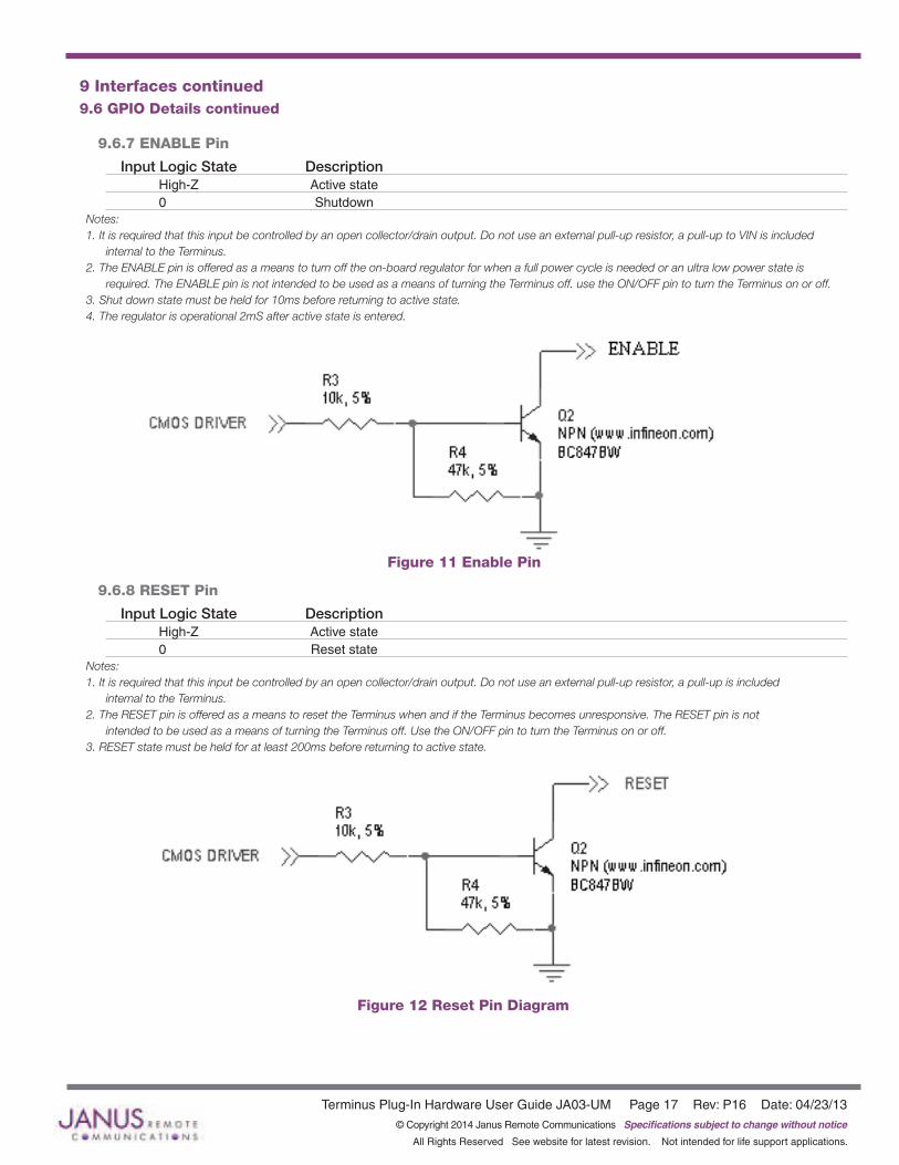
9.6.7 ENABLE Pin
Input Logic State Description High-Z Active state 0 Shutdown Notes:1.Itisrequiredthatthisinputbecontrolledbyanopencollector/drainoutput.Donotuseanexternalpull-upresistor,apull-uptoVINisincluded
internaltotheTerminus.2.TheENABLEpinisofferedasameanstoturnofftheon-boardregulatorforwhenafullpowercycleisneededoranultralowpowerstateis
required.TheENABLEpinisnotintendedtobeusedasameansofturningtheTerminusoff.usetheON/OFFpintoturntheTerminusonoroff.3.Shutdownstatemustbeheldfor10msbeforereturningtoactivestate.4.Theregulatorisoperational2mSafteractivestateisentered.
9.6.8 RESET Pin
Input Logic State Description High-Z Active state 0 Reset state Notes:1.Itisrequiredthatthisinputbecontrolledbyanopencollector/drainoutput.Donotuseanexternalpull-upresistor,apull-upisincluded
internaltotheTerminus.2.TheRESETpinisofferedasameanstoresettheTerminuswhenandiftheTerminusbecomesunresponsive.TheRESETpinisnot
intendedtobeusedasameansofturningtheTerminusoff.UsetheON/OFFpintoturntheTerminusonoroff.3.RESETstatemustbeheldforatleast200msbeforereturningtoactivestate.
Figure 12 Reset Pin Diagram
Figure 11 Enable Pin
Terminus Plug-In Hardware User Guide JA03-UM Page 18 Rev: P16 Date: 04/23/13© Copyright 2014 Janus Remote Communications Specifications subject to change without notice
All Rights Reserved See website for latest revision. Not intended for life support applications.
9 Interfaces continued9.6 GPIO Details continued
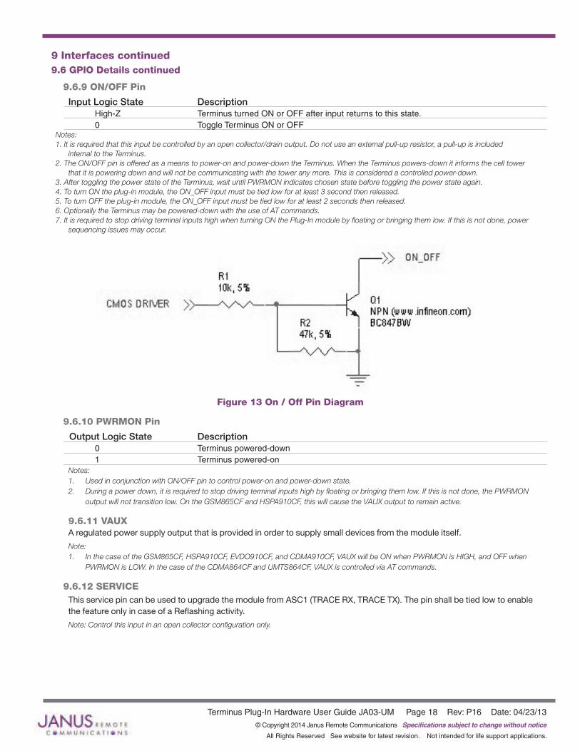
9.6.9 ON/OFF Pin
Input Logic State Description High-Z Terminus turned ON or OFF after input returns to this state. 0 Toggle Terminus ON or OFF
Notes:1.Itisrequiredthatthisinputbecontrolledbyanopencollector/drainoutput.Donotuseanexternalpull-upresistor,apull-upisincluded
internaltotheTerminus.2.TheON/OFFpinisofferedasameanstopower-onandpower-downtheTerminus.WhentheTerminuspowers-downitinformsthecelltower
thatitispoweringdownandwillnotbecommunicatingwiththetoweranymore.Thisisconsideredacontrolledpower-down.3.AftertogglingthepowerstateoftheTerminus,waituntilPWRMONindicateschosenstatebeforetogglingthepowerstateagain.4.ToturnONtheplug-inmodule,theON_OFFinputmustbetiedlowforatleast3secondthenreleased.5.ToturnOFFtheplug-inmodule,theON_OFFinputmustbetiedlowforatleast2secondsthenreleased.6.OptionallytheTerminusmaybepowered-downwiththeuseofATcommands.7.ItisrequiredtostopdrivingterminalinputshighwhenturningONthePlug-Inmodulebyfloatingorbringingthemlow.Ifthisisnotdone,power
sequencingissuesmayoccur.
9.6.10 PWRMON Pin
Output Logic State Description 0 Terminus powered-down 1 Terminus powered-onNotes:1. UsedinconjunctionwithON/OFFpintocontrolpower-onandpower-downstate.2. Duringapowerdown,itisrequiredtostopdrivingterminalinputshighbyfloatingorbringingthemlow.Ifthisisnotdone,thePWRMON outputwillnottransitionlow.OntheGSM865CFandHSPA910CF,thiswillcausetheVAUXoutputtoremainactive.
9.6.11 VAUXA regulated power supply output that is provided in order to supply small devices from the module itself.
Note:1. InthecaseoftheGSM865CF,HSPA910CF,EVDO910CF,andCDMA910CF,VAUXwillbeONwhenPWRMONisHIGH,andOFFwhen PWRMONisLOW.InthecaseoftheCDMA864CFandUMTS864CF,VAUXiscontrolledviaATcommands.
9.6.12 SERVICEThis service pin can be used to upgrade the module from ASC1 (TRACE RX, TRACE TX). The pin shall be tied low to enable the feature only in case of a Reflashing activity.
Note:Controlthisinputinanopencollectorconfigurationonly.
Figure 13 On / Off Pin Diagram

Terminus Plug-In Hardware User Guide JA03-UM Page 19 Rev: P16 Date: 04/23/13© Copyright 2014 Janus Remote Communications Specifications subject to change without notice
All Rights Reserved See website for latest revision. Not intended for life support applications.
9 Interfaces continued9.7 Internal Interfaces
The following section describes all signals that are exposed internally for control of the Terminus.
9.7.1 GPS Reset (GSM865CF) When using a GPS enabled Terminus GSM865CF terminal, GPIO 9 is internally connected to the RESET input of the MS20 GPS module. This allows the application to reset the GPS receiver to a power-on state. The terminal pin GPS RESET can also reset the MS20, but must be controlled via an open-drain output. The MS20 has an internal pull-up resistor thus GPS RESET must not implement an external pull-up resistor.
Input Logic State Description 0 GPS module in reset state 1 GPS module in run state
9.7.2 GPS Suspend (GSM865CF)When using a GPS enabled Terminus GSM865CF terminal, GPIO 8 is internally connected to the SUSPEND input of the MS20 GPS module. This allows the application to set the GPS receiver into a suspended mode of operation to reduce current draw when the GPS receiver is not needed.
Input Logic State Description 0 GPS module in suspended state 1 GPS module in run state
9.7.3 GPS Enable (GSM865CF)When using a GPS enabled Terminus GSM865CF terminal, GPIO 10 is internally connected to the LDO_EN input of the MS20 GPS module. This allows the application to set the GPS receiver into the lowest possible current draw when the GPS receiver is not needed.
Input Logic State Description 0 GPS module is disabled 1 GPS module in run state
9.7.4 GPS LED (GSM865CF)When using a GPS enabled Terminus GSM865CF terminal, the MS20 GPS receiver controls the GPS_LED output. See Figure 10 for recommended connection of LED.
9.7.5 GPS LED (CDMA864CF & UMTS864CF)The CDMA864CF & UMTS864CF terminals come equipped with GPS functionality that is built into the cellular radios. However, the cellular radios have no GPS status output for driving an LED. Instead, these modules have GPIO21 connected to the GPS LED pin of the Terminus. The user application can use this to control an LED or act as an additional GPIO. See Figure 10 for recommended connection of an LED.
9.7.6 GPS LED (HSPA910CF, EVDO910CF, & CDMA910CF)The HSPA910CF, EVDO910CF, & CDMA910CF terminals comes equipped with GPS functionality that is built into the cellular radios. The cellular radios have no GPS output for driving an LED. This module has GPIO2 connected to the GPS LED pin of the Terminus terminal. The user application can use this to control an LED or act as an additional GPIO. See Figure 10 for recommended connection of LED.
Terminus Plug-In Hardware User Guide JA03-UM Page 20 Rev: P16 Date: 04/23/13© Copyright 2014 Janus Remote Communications Specifications subject to change without notice
All Rights Reserved See website for latest revision. Not intended for life support applications.
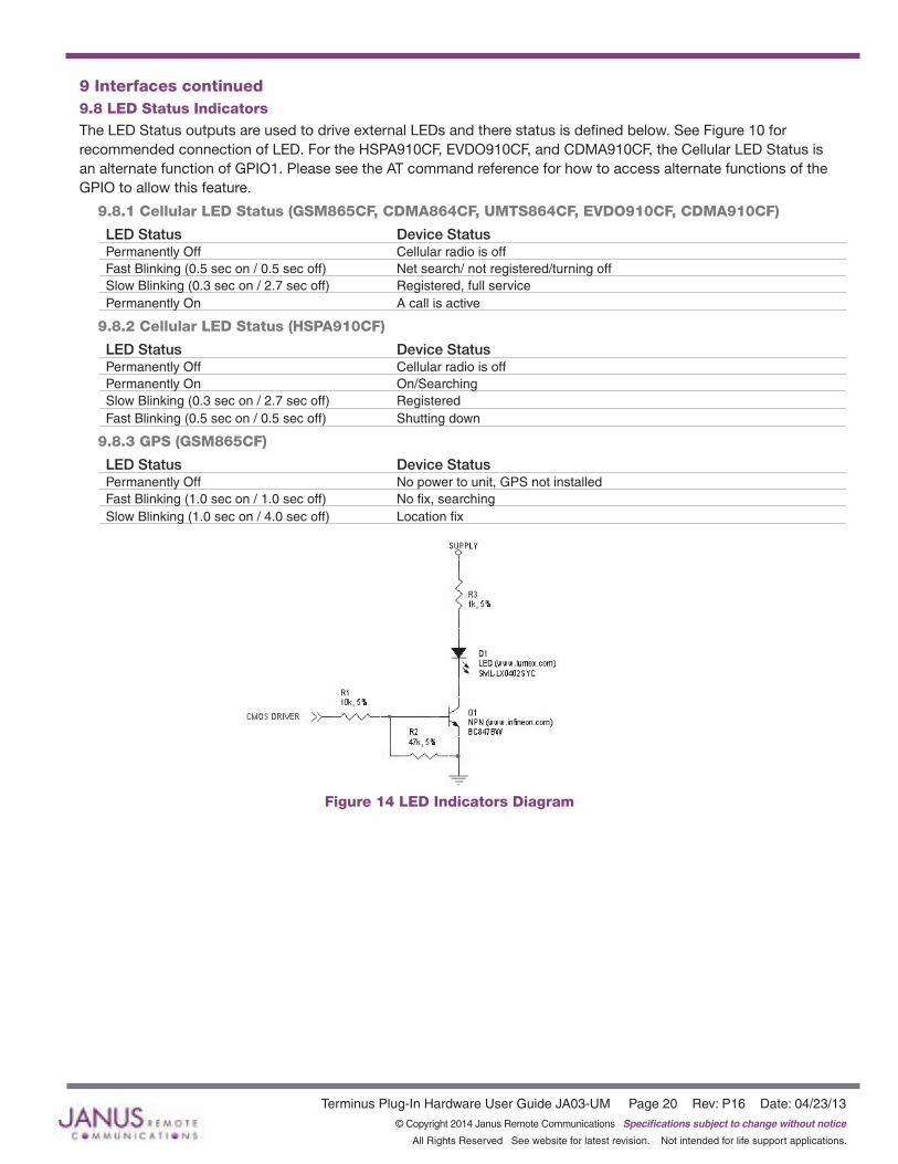
9 Interfaces continued9.8 LED Status IndicatorsThe LED Status outputs are used to drive external LEDs and there status is defined below. See Figure 10 for recommended connection of LED. For the HSPA910CF, EVDO910CF, and CDMA910CF, the Cellular LED Status is an alternate function of GPIO1. Please see the AT command reference for how to access alternate functions of the GPIO to allow this feature.
9.8.1 Cellular LED Status (GSM865CF, CDMA864CF, UMTS864CF, EVDO910CF, CDMA910CF)
LED Status Device StatusPermanently Off Cellular radio is offFast Blinking (0.5 sec on / 0.5 sec off) Net search/ not registered/turning offSlow Blinking (0.3 sec on / 2.7 sec off) Registered, full servicePermanently On A call is active
9.8.2 Cellular LED Status (HSPA910CF)
LED Status Device StatusPermanently Off Cellular radio is offPermanently On On/SearchingSlow Blinking (0.3 sec on / 2.7 sec off) RegisteredFast Blinking (0.5 sec on / 0.5 sec off) Shutting down
9.8.3 GPS (GSM865CF)
LED Status Device StatusPermanently Off No power to unit, GPS not installedFast Blinking (1.0 sec on / 1.0 sec off) No fix, searchingSlow Blinking (1.0 sec on / 4.0 sec off) Location fix
Figure 14 LED Indicators Diagram

Terminus Plug-In Hardware User Guide JA03-UM Page 21 Rev: P16 Date: 04/23/13© Copyright 2014 Janus Remote Communications Specifications subject to change without notice
All Rights Reserved See website for latest revision. Not intended for life support applications.
9 Interfaces continued
9.9 RF InterfaceThere are 3 possible RF interfaces on the Termins Plug-in Modules. The non-GPS GSM865CF has only the cellular antenna jack. The GSM865CF (GPS Enabled), UMTS864CF, and CDMA864CF have both cellular and GPS antenna interfaces. The HSPA910CF (GPS Enabled) has the cellular, RX diversity, and GPS antenna jacks. The specifications and requirements for these are as follows:
Note: YoumustaccesstheCellular/Div/GPSconnectionsviatheSMTGSCconnectionsiftheydonotincludeaGSCtoSMAconnector.These signalsareNOTelectricallyconnectedelsewhereontheboard.
9.9.1 Cellular Antenna
9.9.1.1 GSM865CF Antenna Interface: Type: Murata GSC - MALE (Murata Part #MM9329-2700RA1)
Pin Description Center Pin RF signal Outer Conductor Signal ground
9.9.1.2 Certified GSM Antenna
TBD 9.9.1.3 CDMA864CF Antenna InterfaceThis module includes coax GSC to SMA (F) bulkhead connector that is mounted to the plug-in module. Type: GSC to SMA (F), 200mm Cable (Janus Part #MC-0168)
Pin Description Center Pin RF signal Outer Conductor Signal ground
9.9.1.4 Certified CDMA Antenna(Janus Part number ANT-0073-G)
Frequency: 824-894 MHz, 1850-1990 MHzGain: 3 dBiVSWR: 2:1 maxImpedance: 50 W nominalPower: 5W maxOperating Temperature: -40°C to 85°CLength: 6.75” with 90° angle; 7.75” when straight
9.9.1.5 UMTS864CF Antenna InterfaceThis module includes coax GSC to SMA (F) bulkhead connector that is mounted to the plug-in module. Type: GSC to SMA (F), 200mm Cable (Janus Part #MC-0168)
Pin Description Center Pin RF signal Outer Conductor Signal ground
9.9.1.6 Certified UMTS Antenna TBD
Terminus Plug-In Hardware User Guide JA03-UM Page 22 Rev: P16 Date: 04/23/13© Copyright 2014 Janus Remote Communications Specifications subject to change without notice
All Rights Reserved See website for latest revision. Not intended for life support applications.
9 Interfaces continued9.9 RF Interface continued
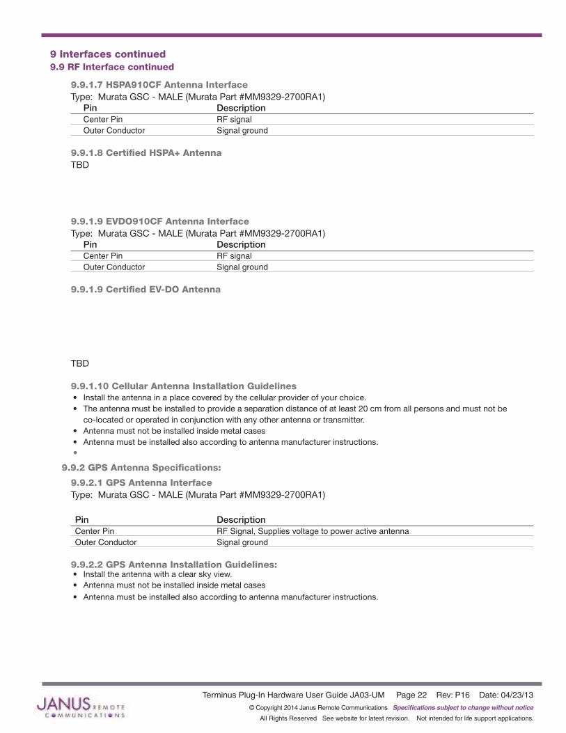
9.9.1.7 HSPA910CF Antenna InterfaceType: Murata GSC - MALE (Murata Part #MM9329-2700RA1)
Pin Description Center Pin RF signal Outer Conductor Signal ground
9.9.1.8 Certified HSPA+ Antenna TBD
9.9.1.9 EVDO910CF Antenna InterfaceType: Murata GSC - MALE (Murata Part #MM9329-2700RA1)
Pin Description Center Pin RF signal Outer Conductor Signal ground
9.9.1.9 Certified EV-DO Antenna
TBD 9.9.1.10 Cellular Antenna Installation Guidelines• Install the antenna in a place covered by the cellular provider of your choice. • The antenna must be installed to provide a separation distance of at least 20 cm from all persons and must not be
co-located or operated in conjunction with any other antenna or transmitter.• Antenna must not be installed inside metal cases• Antenna must be installed also according to antenna manufacturer instructions.•
9.9.2 GPS Antenna Specifications:
9.9.2.1 GPS Antenna InterfaceType: Murata GSC - MALE (Murata Part #MM9329-2700RA1)
Pin Description Center Pin RF Signal, Supplies voltage to power active antenna Outer Conductor Signal ground
9.9.2.2 GPS Antenna Installation Guidelines:• Install the antenna with a clear sky view. • Antenna must not be installed inside metal cases• Antenna must be installed also according to antenna manufacturer instructions.
Terminus Plug-In Hardware User Guide JA03-UM Page 23 Rev: P16 Date: 04/23/13© Copyright 2014 Janus Remote Communications Specifications subject to change without notice
All Rights Reserved See website for latest revision. Not intended for life support applications.
9 Interfaces continued9.10 SIM Card Interface
GSM865CF, UMTS864CF and HSPA910CFThe SIM Card Interface allows the Terminus to accept the subscriber card provided by the cellular telephone provider. It can accommodate a 1.8V or 3.0V SIM card and complies with the Phase 2 GSM 11.14 standard. Optional SIM IC. Consult factory representative.
9.11 Header Interface Mounting OptionsThe Plug-In Modules’ header pin length has been chosen to allow for direct solder mount to a PCB of standard thickness. If the user wishes to socket the Plug-In Module, they may do so as well by using the below part numbers for reference:
Samtec 25 pin header: TSM-125-04-L-SV-ASamtec 24 pin header: TSM-124-04-L-SV-AMating Samtec 25 pin connector: SLW-125-01-G-SMating Samtec 24 pin connector: SLW-124-01-G-S
Please note there are no Samtec SMT single row mating connectors. The only mating connector available is the above listed THT version.
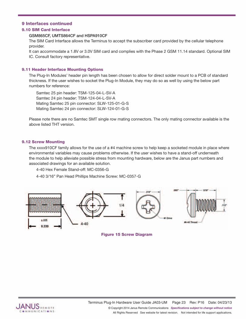
9.12 Screw MountingThe xxxx910CF family allows for the use of a #4 machine screw to help keep a socketed module in place where environmental variables may cause problems otherwise. If the user wishes to have a stand-off underneath the module to help alleviate possible stress from mounting hardware, below are the Janus part numbers and associated drawings for an available solution.
4-40 Hex Female Stand-off: MC-0356-G
4-40 3/16” Pan Head Phillips Machine Screw: MC-0357-G
Figure 15 Screw Diagram
Terminus Plug-In Hardware User Guide JA03-UM Page 24 Rev: P16 Date: 04/23/13© Copyright 2014 Janus Remote Communications Specifications subject to change without notice
All Rights Reserved See website for latest revision. Not intended for life support applications.
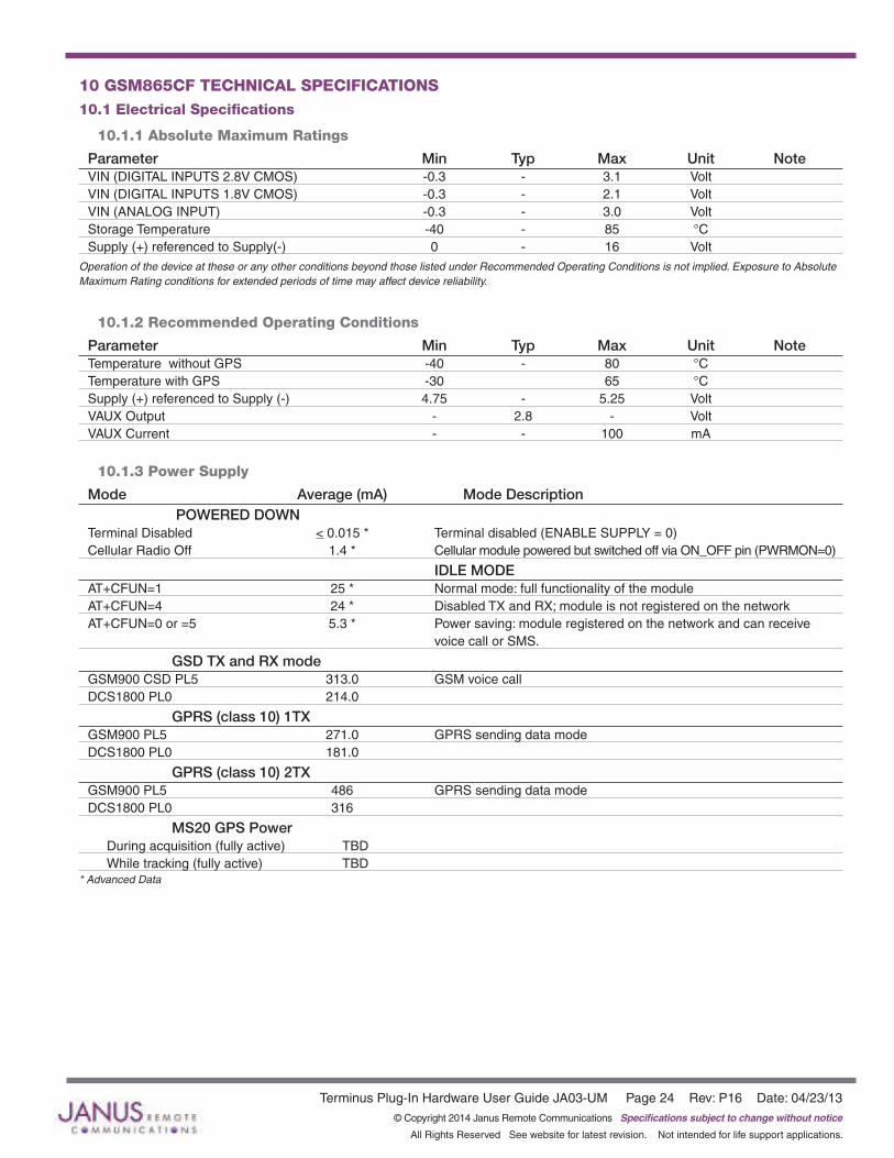
10 GSM865CF TECHNICAL SPECIFICATIONS10.1 Electrical Specifications
10.1.1 Absolute Maximum Ratings
Parameter Min Typ Max Unit Note VIN (DIGITAL INPUTS 2.8V CMOS) -0.3 - 3.1 Volt VIN (DIGITAL INPUTS 1.8V CMOS) -0.3 - 2.1 VoltVIN (ANALOG INPUT) -0.3 - 3.0 Volt Storage Temperature -40 - 85 °C Supply (+) referenced to Supply(-) 0 - 16 Volt
Operation of the device at these or any other conditions beyond those listed under Recommended Operating Conditions is not implied. Exposure to Absolute Maximum Rating conditions for extended periods of time may affect device reliability.
10.1.2 Recommended Operating Conditions
Parameter Min Typ Max Unit Note Temperature without GPS -40 - 80 °C Temperature with GPS -30 65 °CSupply (+) referenced to Supply (-) 4.75 - 5.25 Volt VAUX Output - 2.8 - Volt VAUX Current - - 100 mA
10.1.3 Power Supply
Mode Average (mA) Mode Description POWERED DOWN Terminal Disabled < 0.015 * Terminal disabled (ENABLE SUPPLY = 0)Cellular Radio Off 1.4 * Cellular module powered but switched off via ON_OFF pin (PWRMON=0)
IDLE MODEAT+CFUN=1 25 * Normal mode: full functionality of the moduleAT+CFUN=4 24 * Disabled TX and RX; module is not registered on the networkAT+CFUN=0 or =5 5.3 * Power saving: module registered on the network and can receive voice call or SMS.
GSD TX and RX modeGSM900 CSD PL5 313.0 GSM voice callDCS1800 PL0 214.0
GPRS (class 10) 1TXGSM900 PL5 271.0 GPRS sending data modeDCS1800 PL0 181.0
GPRS (class 10) 2TXGSM900 PL5 486 GPRS sending data mode DCS1800 PL0 316
MS20 GPS Power During acquisition (fully active) TBD While tracking (fully active) TBD
* Advanced Data
Terminus Plug-In Hardware User Guide JA03-UM Page 25 Rev: P16 Date: 04/23/13© Copyright 2014 Janus Remote Communications Specifications subject to change without notice
All Rights Reserved See website for latest revision. Not intended for life support applications.
10 GSM865CF TECHNICAL SPECIFICATIONS continued10.1 Electrical Specification continued
10.1.4 I/O Levels
10.1.4.1 Standard Interface LevelsParameter Min Typ Max Unit NoteInput Voltage High - Vih 2.1 - 3.0 Volt Input Voltage Low - Vil 0 - 0.5 Volt Output Voltage High - Voh 2.2 - 3.0 Volt Output Voltage Low - Vol 0 - 0.35 Volt Typical Current Source/Sink capability = 1mA/1uA
10.1.4.2 Cellular LED Output Levels
Parameter Min Typ Max Unit NoteOutput Voltage High - Voh 1.65 - 2.0 Volt Output Voltage Low - Vol 0 - 0.35 Volt Typical Current Source = 1mA
10.1.4.3 Reset Pin Input Levels
Parameter Min Typ Max Unit NoteInput Voltage High - Vih 1.8 - 2.1 Volt Input Voltage Low - Vil 0 - 0.2 Volt
It is required that this input be controlled by an Open Collector/Drain Output. Do not use an external pull-up resistor, a pull-up is included internal to the Terminus.
10.1.4.4 ADC Levels - ADC1 & ADC2Parameter Min Typ Max Unit NoteVoltage Range 0 - 2.0 Volt AD Conversion - - 11 Bits Resolution - - < 1 mV
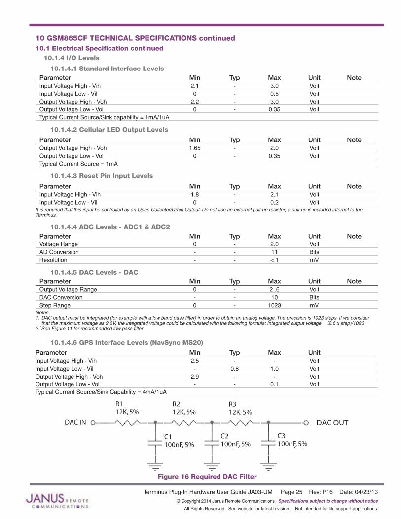
10.1.4.5 DAC Levels - DACParameter Min Typ Max Unit NoteOutput Voltage Range 0 - 2 .6 Volt DAC Conversion - - 10 Bits Step Range 0 - 1023 mV
Notes 1. DAC output must be integrated (for example with a low band pass filter) in order to obtain an analog voltage. The precision is 1023 steps. If we consider that the maximum voltage as 2.6V, the integrated voltage could be calculated with the following formula: Integrated output voltage = (2.6 x step)/1023 2.`See Figure 11 for recommended low pass filter
10.1.4.6 GPS Interface Levels (NavSync MS20)
Parameter Min Typ Max Unit Input Voltage High - Vih 2.5 - - Volt Input Voltage Low - Vil - 0.8 1.0 Volt Output Voltage High - Voh 2.9 - - VoltOutput Voltage Low - Vol - - 0.1 Volt Typical Current Source/Sink Capability = 4mA/1uA
R212K, 5%
R312K, 5%
R112K, 5%
DAC IN
C1100nF, 5%
C2100nF, 5%
C3100nF, 5%
DAC OUT
Figure 16 Required DAC Filter
Terminus Plug-In Hardware User Guide JA03-UM Page 26 Rev: P16 Date: 04/23/13© Copyright 2014 Janus Remote Communications Specifications subject to change without notice
All Rights Reserved See website for latest revision. Not intended for life support applications.
10 GSM865CF TECHNICAL SPECIFICATIONS continued10.1 Electrical Specification continued
10.1.5 GSM Cellular Antenna Interfaces
10.1.5.1 Antenna Specifications:Frequency Range GSM850: TX: 824.2 - 850.0Mhz RX: 869.2 - 895.0Mhz GSM900 Primary: TX: 890.2 - 914.8Mhz RX: 935.2 - 959.8Mhz GSM900 Extended: TX: 880.2 - 889.8Mhz RX: 925.2 - 934.8Mhz PCS1900: TX: 1850.2 - 1909.8Mhz RX: 1930.2 - 1989.8MhzBandwidth 70MHz in GSM850, 80 MHz in GSM900, 170 MHz in DCS, 140 MHz in PCS bandGain 1.4 dBi @ 900 MHz, 3dBi @ 1800 MHz, 1.4 dBi @ 850 MHz, 3dBi @ 1900 MHzImpedance 50 WInput Power >2 W peak powerVSWR absolute max ≤ 10:1VSWR recommended ≤ 2:1
10.1.6 GSM GPS Antenna Interfaces
10.1.6.1 Antenna Specifications Input Voltage Range 2.9V ±5%Frequency Range 1575.42 ± 3 MHzGain Depends on cable type and lengthImpedance 50 WVSWR ≤.1. 5:1Current Consumption 30 mA (MAX), 20 mA TYP
Note:GSM865CFGPSantennainterfaceonlyavailablebyoption,otherwisenotpopulated
10.1.7 Input / Output Lines
Input Lines (MIC + & MIC-)Parameter GSM865CFLine Coupling AC (*)Line Type BalancedCoupling Capacitor ≥100 nFDifferential Input Impedance 50 k WDifferential Input Voltage ≤1,03 Vpp @ HSMicG = 0 dBVolume Steps 7Volume Level Step 6 dB/Step
*Warning:Thelinecouplingdefinition“AC”meansthatthesignalsfromthemicrophonemustbeconnectedtotheinputlinesofthemodulethroughcapacitors,notlessthan100nF.Bynotrespectingthisconstraint,theinputstagemaybedamaged.
Output Lines (EAR+ & EAR-)Parameter GSM865CFLine Coupling DCOutput Load Impedance ≥14 WDifferential Output Impedance 4 WSignal Bandwidth 150-4000 Hz @ -3 dBDifferential Output Voltage (max) 1.31 Vrms (open circuit)Volume Steps 10Volume Level Step 2 dB/Step

Terminus Plug-In Hardware User Guide JA03-UM Page 27 Rev: P16 Date: 04/23/13© Copyright 2014 Janus Remote Communications Specifications subject to change without notice
All Rights Reserved See website for latest revision. Not intended for life support applications.
Figure 17 GSM865CF Mechanical Dimensions
10 GSM865CF TECHNICAL SPECIFICATIONS continued10.2 Mechanical Specifications

Terminus Plug-In Hardware User Guide JA03-UM Page 28 Rev: P16 Date: 04/23/13© Copyright 2014 Janus Remote Communications Specifications subject to change without notice
All Rights Reserved See website for latest revision. Not intended for life support applications.
10 GSM865CF TECHNICAL SPECIFICATIONS continued10.3 MS20 GPS Specifications
10.3.1 Features: • High sensitivity of –159 dBm in tracking & -144 dBm in acquisition• Assisted/Autonomous operation• 12 channels• SBAS (WASS/EGNOS/MSAS)
10.3.2 Specifications:
Specifications Description Notes GPS Channels 12 tracking (48 acquisition) Frequency 1575.42 MHz – L1 C/A Code TTFF Cold Start 34 seconds 1,7 TTFF Warm Start 32 seconds 1,7 TTFF Hot Start 1.5 seconds 1,7 Re-Acquisition Time <1 second 2 Acquisition Sensitivity (fix not available) TTFF (Hot) with all signals at –138 dBm: 30 s 3 Acquisition Sensitivity (dBm) -144 dBm 4 Tracking Sensitivity (dBm) -159 dBm 5 Acquisition Sensitivity SBAS Satellites (dBm) TBD 6 Tracking Sensitivity SBAS Satellites (dBm) TBD 6 Static Accuracy (without SBAS) 50% confidence (CEP) 1.7 m 7 95% confidence 2.9 m Static Accuracy (with SBAS) 50% confidence (CEP) 1.2 m 8 95% confidence 2.4 m Maximum Horizontal Speed 515 m/s (1000 Knots) 9 Maximum Altitude 18 Km (60000 feet) 9 Maximum Acceleration, Jerk 4 g, 7 g/s Notes: 1.TheseareRMSvalues 2.Maximumsensitivity–147dBm 3.Simulatortest,allsignalsatspecifiedpowerlevel 4.Estimated 5.Simulatortest,continuousfixwithallsignalsatspecifiedpowerlevel 6.Simulatortestwithsignalatspecifiedpowerlevel 7.Open-sky,24hrsstatistic,activeantenna(signalrangebetween30and49dB/Hz) 8.Opensky,24hrsstatistic,activeantenna(WAASsignalused) 9.LimitedbyInternationalTrafficinArmsRegulation(ITAR)

Terminus Plug-In Hardware User Guide JA03-UM Page 29 Rev: P16 Date: 04/23/13© Copyright 2014 Janus Remote Communications Specifications subject to change without notice
All Rights Reserved See website for latest revision. Not intended for life support applications.
10 GSM865CF TECHNICAL SPECIFICATIONS continued 10.4 GSM865CF Getting Started
10.4.1 Setting Up A Terminal Emulator For Use With The GSM865CF Terminus
10.4.1.1 Set UpTo interface with the module, connect the serial interface to a PC and use a terminal emulation program such as Microsoft® Hyperterminal. Set the interface parameters as follows:
• Baud Rate: 115.2 kbps• Bits: 8• Stop Bits: 1• Parity: None• Hardware Handshaking: Yes
10.4.1.2 Set The Terminal to Auto-Bauding• Enter AT<cr> from terminal and wait for OK• Enter AT+IPR=0<cr> and wait for OK• Terminus is now set for auto data rate detection
10.4.1.3 Verify Your Terminal and Firmware Version• Enter AT+CGMM and wait for the response
The response will be the Telit module’s model number without a command echo.• Enter AT+CGMR and wait for the response
The response will be the Telit module’s current firmware without a command echo.
Please confirm your model and firmware with the one listed in section 2.1
10.4.2 Powering ON/OFF
10.4.2.1 Turn the module ON through the following method:• Pull ON/OFF signal (Pin 19) to ground for three (3) seconds, then release.
The Terminus module is fully operational after 4 seconds. Logging onto a network may take longer than this and is outside the control of the Terminus.
10.4.2.2 There are two ways to switch OFF the module as described below.• Use the appropriate AT command (AT#SHDN)• Pull ON/OFF signal (Pin 19) to ground for two (2) seconds, then release.
Terminus Plug-In Hardware User Guide JA03-UM Page 30 Rev: P16 Date: 04/23/13© Copyright 2014 Janus Remote Communications Specifications subject to change without notice
All Rights Reserved See website for latest revision. Not intended for life support applications.
10 GSM865CF TECHNICAL SPECIFICATIONS continued 10.4 GSM865CF Getting Started continued
10.4.3 Setting up Service – Network Settings
10.4.3.1 Set UpThe network settings for the Terminus will vary depending on the cellular carrier you are using. Below are two of the North American cases for these settings.
For T-mobile® & MNVO (Raco®, Sensor Logic®, Nexaira® Jasper Wireless®) Enter:
• AT#SELINT=2 //use of most recent AT command set • AT#STIA=2,10 or AT#STIA=1 // enable SAT – SIM Application Tool-Kit • AT#BND=3 // default bands to 850/1900 • AT#AUTOBND=1 // enable Quad band system selection • AT#PLMNMODE=1 // enable EONS (enhanced operator naming scheme) • AT&P0 // save profile • AT&W0 // save setting • AT#ENS=0
For AT&T/Cingular® & MNVO (Kore®, Aeris®, nPhase®) Enter:
• AT#SELINT=2 //use of most recent AT command set • AT#ENS=1 // AT&T/Cingular configuration (SAT, BND, AUTONBND, PLMNMODE, plus Cingular® specific
ENS requirements)
If Terminus is being used in a different country or with a different carrier please refer to Telit AT command reference document regarding the use of the AT#BND command to set the proper frequency band.
Important: After entering either of the sets of settings above power the Terminus OFF and then ON. It is now ready for use.
10.4.3.2 Check Network Status (assuming you have a valid SIM card installed)Enter AT+CREG? <cr> And wait for response.
Response will be +CREG:0,1 or +CREG: 0,5 meaning the device is registered to the home network or roaming, respectively. If response is different than this please refer to the Telit AT command reference document for more information.
10.4.3.3 Check Signal Quality Enter AT+CSQ<cr> And wait for response +CSQ:<rssi>,<ber>
<rssi> Signal Strength 99 Not known or not detectable 0-31 dBm = (rssi * 2) –113
Example: A result of 31 indicates -51dBm or greater.
An rssi value of >=10 in typical applications is fine and you will usually see about 12-20 in normal to good signal, but note that worst case it can be lower, still register and perform normal functions.
10.4.4 Making a Voice Call
10.4.4.1 Set Up Voice call mode allows you to use a telephone handset to communicate with a properly equipped subscriber unit.
• Set the call mode to voice Enter AT+FCLASS=8<cr> and wait for response OK
• Set the audio path of the Terminus Enter AT#CAP=0
• Dial the phone number Enter ATD <8885551234>; <cr>
• To disconnect the call enter ATH<cr>
Terminus Plug-In Hardware User Guide JA03-UM Page 31 Rev: P16 Date: 04/23/13© Copyright 2014 Janus Remote Communications Specifications subject to change without notice
All Rights Reserved See website for latest revision. Not intended for life support applications.
10 GSM865CF TECHNICAL SPECIFICATIONS continued 10.4 GSM865CF Getting Started continued
10.4.5 Sending an SMS
10.4.5.1 Set UpSMS (Select Message Service) mode allows you to send a text message (max 160 characters) to a SMS capable subscriber unit.
• Set the SMS mode to text. This must be entered every power cycle. AT+CMGF=1<cr>
• To enter the receiving subscriber unit phone number and message enter: AT+CMGS=”8885551234” Wait for response”>” then enter message text Enter “ctrl z” <cr> to end the message
10.4.6 Making a GPRS Data Call
10.4.6.1 Set UpGPRS is a data service that uses Packet Data Protocol (PDP).
• Set up the PDP context parameters Enter AT+CGDCONT=1, “IP”, “APN”, “0.0.0.0”,0,0<cr> Where APN is specific to the service provider being used.
• Set the minimum Quality of Service profile Enter AT+CGQMIN=1,0,0,0,0,0
• Set up the desired Quality of Service profile Enter AT+CGQREQ=1,0,0,3,0,0
• Activate the PDP context Enter AT#SGACT=1,1,”v”, “p” Where v is your user ID and p is your password. If these are not set replace with “”,””
• Open the socket connection Enter AT#SD=1,0,IPP,IPA,0,0,0 Look for response “CONNECT”. This opens a remote connection via socket IPP = the remote host port of the server you are trying to connect to. (0 to 65535) IPA = the IP address of the server hyou are trying to connect to in the format: “xxx.xxx.xxx.xxx” ‘Port’= the remote host port to contact provided by carrier (0 to 65535)
• At this point a data session is active and data can be sent from the Terminus to the remote device and visa versa. • To exit the data session and return to command mode, send the characters”+++” and wait for the OK response • Enter AT#SH=1 to close the socket
10.4.7 Making a GPS Data Call
10.4.7.1 Set UpIn order to access the GPS on the GSM865CF, the NavSync GPS port must be used. After connecting to that port, open a terminal window with the following parameters:
• Baud Rate: 9600 bps• Bits: 8• Stop Bits: 1• Parity: None• Hardware Handshaking: No
Simply open the port and an NMEA data stream will begin to appear. The specific commands to adjust this stream to the application are in the MS20 User Guide. Available in the evaluation kit CD or online at http://www.janus-rc.com/gsm865cf.html
10.4.8 Further Instructions On utilizing different commands for other applications than those described here, please refer to these reference documents, listed in section 2.1
• Telit AT Commands Reference Guide• Telit GC864 Software User Guide• Telit Easy GPRS User Guide

Terminus Plug-In Hardware User Guide JA03-UM Page 32 Rev: P16 Date: 04/23/13© Copyright 2014 Janus Remote Communications Specifications subject to change without notice
All Rights Reserved See website for latest revision. Not intended for life support applications.
11 CDMA864CF TECHNICAL SPECIFICATIONS11.1 Electrical Specifications
11.1.1 Absolute Maximum Ratings
Parameter Min Typ Max Unit Note VIN (DIGITAL INPUTS 2.6V CMOS) -0.3 - 3.0 Volt VIN (DIGITAL INPUTS 1.8V CMOS) -0.3 - 2.1 VoltVIN (ANALOG INPUT) -0.3 - 3.0 Volt Storage Temperature -40 - 85 °C Supply (+) referenced to Supply (-) 0 - 16 Volt OperationofthedeviceattheseoranyotherconditionsbeyondthoselistedunderRecommendedOperatingConditionsisnotimplied.Exposureto
AbsoluteMaximumRatingconditionsforextendedperiodsoftimemayaffectdevicereliability.
11.1.2 Recommended Operating Conditions
Parameter Min Typ Max Unit Note Temperature -30 - 80 °C Supply (+) referenced to Supply (-) 4.75 - 5.25 Volt VAUX Output - 2.65 - Volt VAUX Current - - 100 mA
11.1.3 Power Supply
Mode Average (mA) Mode Description POWERED DOWN Terminal Disabled < 15µA Terminal disabled (ENABLE SUPPLY = 0)Cellular Radio Off 1.4mA Cellular module powered but switched off via ON_OFF pin (PWRMON=0)Cellular 513 Transmission at max level (23 - 24Bm)PCS 595 Transmission at max level (23 - 24 dBm)Cellular 134 Transmission at min level (-50 dBm)PCS 144 Transmission at min level (-50 dBm)GPS ON Idle (AT+CFUN=1) 94 Normal mode: full functionality of the module Sleep (AT+CFUN=4) 93 Disabled TX and RX; module is not registered on the network Low Power (AT+CFUN=0 or 5) N/A (Note 1) Power saving: module registered on the network and can receive voice call or SMSGPS OFF Idle (AT+CFUN=1) 46 Normal mode: full functionality of this module Sleep (AT+CFUN=4) 45 Disabled TX and RX; module is not registered on the network Low Power (AT+CFUN=0 or 5) 5 Power saving: module registered on the network and can receive voice call or SMSNotes:Theaveragecurrentconsumptionduringtransmissionsdependsonthepowerlevelatwhichthedeviceisrequestedtotransmitbythenetwork.DatatakenwithUSBdisconnected.Thethermaldesignfortheapplicationanditspowersupplyneedstotakethefollowingparametersintoaccount.Note1:LowpowermodeisnotusablewithGPSON(AT$GPSP=1)

Terminus Plug-In Hardware User Guide JA03-UM Page 33 Rev: P16 Date: 04/23/13© Copyright 2014 Janus Remote Communications Specifications subject to change without notice
All Rights Reserved See website for latest revision. Not intended for life support applications.
11.1.4 I/O Levels
11.1.4.1 Standard Interface LevelsParameter Min Typ Max Unit NoteInput Voltage High - Vih 1.69 - 2.9 Volt Input Voltage Low - Vil -0.3 - 0.91 Volt Output Voltage High - Voh 2.15 - 2.6 Volt Output Voltage Low - Vol 0 - 0.45 Volt Typical Current Source/Sink capability = 1mA/1uA
11.1.4.2 Cellular LED Output LevelsParameter Min Typ Max Unit NoteOutput Voltage High - Voh 1.35 - 1.8 Volt Output Voltage Low - Vol 0 - 0.45 Volt Typical Current Source = 1mA
11.1.4.3 Reset Pin Input Levels
Parameter Min Typ Max Unit Input Voltage High - Vih 2.0 - 2.6 Volt Input Voltage Low - Vil 0 - 0.2 Volt
It is required that this input be controlled by an Open Collector/Drain Output. Do not use an external pull-up resistor, a pull-up is included internal to the Terminus.
11.1.4.4 ADC Levels - ADC1 & ADC2
Parameter Min Typ Max Unit Input Voltage Range 0 - 2.5 Volt AD Conversion - - 8 Bits
11.1.4.5 DAC Levels - DACParameter Min Typ Max Unit Output Voltage Range 0 - 2.6 Volt DAC Conversion - - 8 BitsStep Range 0 - 255 Steps
Notes 1. DAC output must be integrated (for example with a low band pass filter) in order to obtain an analog voltage. The precision is 1023 steps. If we consider that the maximum voltage as 2.6V, the integrated voltage could be calculated with the following formula: Integrated output voltage = (2.6 x step)/1023 2.`See Figure 11 for recommended low pass filter
11 CDMA864CF TECHNICAL SPECIFICATIONS continued11.1 Electrical Specifications continued
Terminus Plug-In Hardware User Guide JA03-UM Page 34 Rev: P16 Date: 04/23/13© Copyright 2014 Janus Remote Communications Specifications subject to change without notice
All Rights Reserved See website for latest revision. Not intended for life support applications.
11 CDMA864CF TECHNICAL SPECIFICATIONS continued11.1 Electrical Specifications continued
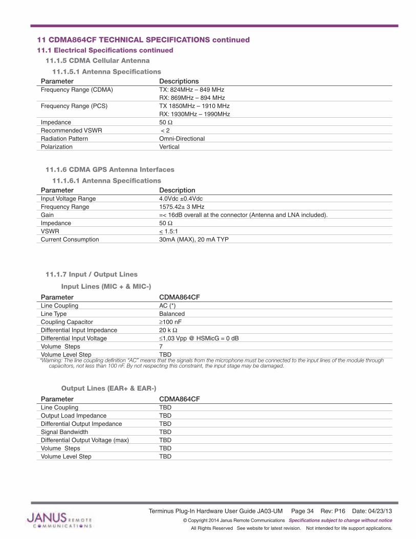
11.1.5 CDMA Cellular Antenna
11.1.5.1 Antenna SpecificationsParameter DescriptionsFrequency Range (CDMA) TX: 824MHz – 849 MHz RX: 869MHz – 894 MHzFrequency Range (PCS) TX 1850MHz – 1910 MHz RX: 1930MHz – 1990MHzImpedance 50 WRecommended VSWR < 2Radiation Pattern Omni-DirectionalPolarization Vertical
11.1.6 CDMA GPS Antenna Interfaces
11.1.6.1 Antenna SpecificationsParameter DescriptionInput Voltage Range 4.0Vdc ±0.4VdcFrequency Range 1575.42± 3 MHzGain =< 16dB overall at the connector (Antenna and LNA included).Impedance 50 WVSWR < 1.5:1 Current Consumption 30mA (MAX), 20 mA TYP
11.1.7 Input / Output Lines
Input Lines (MIC + & MIC-)
Parameter CDMA864CFLine Coupling AC (*)Line Type BalancedCoupling Capacitor ≥100 nFDifferential Input Impedance 20 k WDifferential Input Voltage ≤1,03 Vpp @ HSMicG = 0 dBVolume Steps 7Volume Level Step TBD*Warning:Thelinecouplingdefinition“AC”meansthatthesignalsfromthemicrophonemustbeconnectedtotheinputlinesofthemodulethrough
capacitors,notlessthan100nF.Bynotrespectingthisconstraint,theinputstagemaybedamaged.
Output Lines (EAR+ & EAR-)
Parameter CDMA864CFLine Coupling TBDOutput Load Impedance TBDDifferential Output Impedance TBDSignal Bandwidth TBDDifferential Output Voltage (max) TBDVolume Steps TBDVolume Level Step TBD
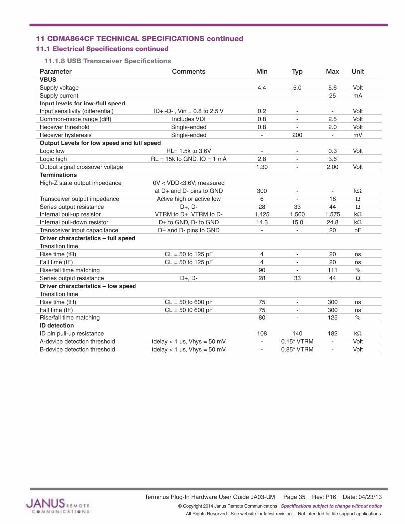
Terminus Plug-In Hardware User Guide JA03-UM Page 35 Rev: P16 Date: 04/23/13© Copyright 2014 Janus Remote Communications Specifications subject to change without notice
All Rights Reserved See website for latest revision. Not intended for life support applications.
11.1.8 USB Transceiver Specifications
Parameter Comments Min Typ Max UnitVBUS Supply voltage 4.4 5.0 5.6 VoltSupply current 25 mAInput levels for low-/full speed Input sensitivity (differential) |D+ -D-|, Vin = 0.8 to 2.5 V 0.2 - - VoltCommon-mode range (diff) Includes VDI 0.8 - 2.5 VoltReceiver threshold Single-ended 0.8 - 2.0 VoltReceiver hysteresis Single-ended - 200 - mVOutput Levels for low speed and full speed Logic low RL= 1.5k to 3.6V - - 0.3 VoltLogic high RL = 15k to GND, IO = 1 mA 2.8 - 3.6 Output signal crossover voltage 1.30 - 2.00 VoltTerminations High-Z state output impedance 0V < VDD<3.6V; measured at D+ and D- pins to GND 300 - - kWTransceiver output impedance Active high or active low 6 - 18 WSeries output resistance D+, D- 28 33 44 WInternal pull-up resistor VTRM to D+, VTRM to D- 1.425 1.500 1.575 kWInternal pull-down resistor D+ to GND, D- to GND 14.3 15.0 24.8 kWTransceiver input capacitance D+ and D- pins to GND - - 20 pFDriver characteristics – full speed Transition time Rise time (tR) CL = 50 to 125 pF 4 - 20 nsFall time (tF) CL = 50 to 125 pF 4 - 20 nsRise/fall time matching 90 - 111 %Series output resistance D+, D- 28 33 44 WDriver characteristics – low speed Transition time Rise time (tR) CL = 50 to 600 pF 75 - 300 nsFall time (tF) CL = 50 t0 600 pF 75 - 300 nsRise/fall time matching 80 - 125 %ID detection ID pin pull-up resistance 108 140 182 kWA-device detection threshold tdelay < 1 µs, Vhys = 50 mV - 0.15* VTRM - VoltB-device detection threshold tdelay < 1 µs, Vhys = 50 mV - 0.85* VTRM - Volt
11 CDMA864CF TECHNICAL SPECIFICATIONS continued11.1 Electrical Specifications continued
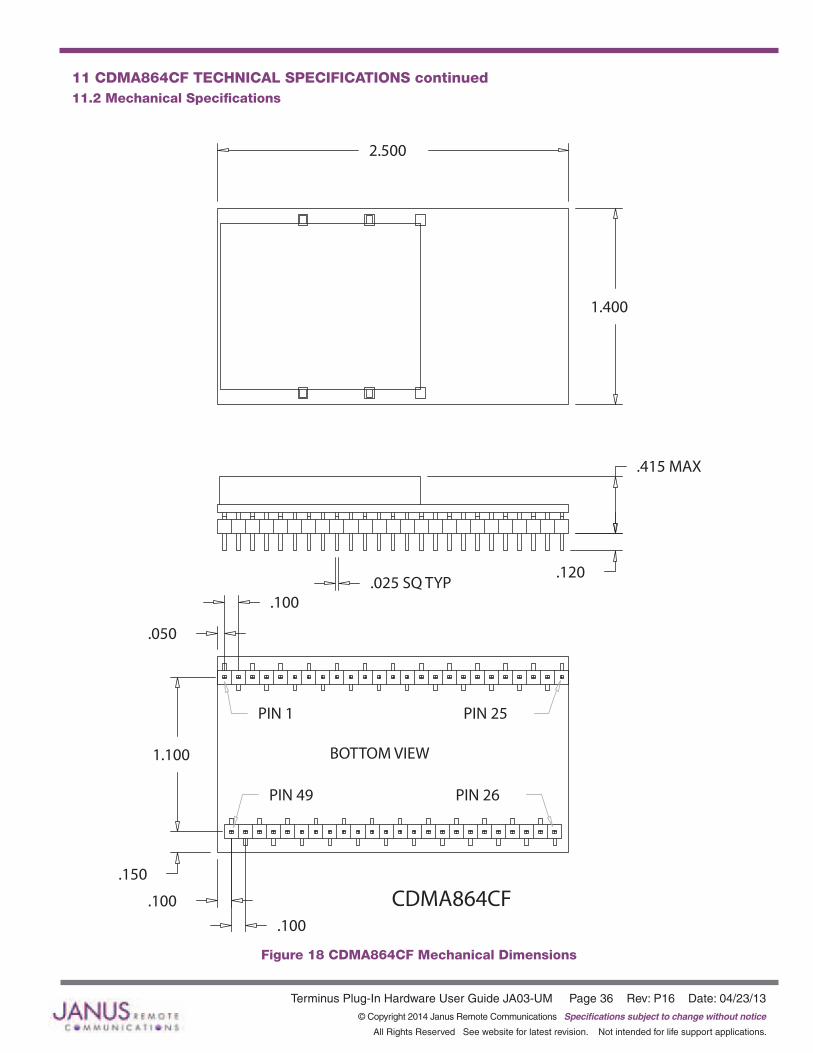
Terminus Plug-In Hardware User Guide JA03-UM Page 36 Rev: P16 Date: 04/23/13© Copyright 2014 Janus Remote Communications Specifications subject to change without notice
All Rights Reserved See website for latest revision. Not intended for life support applications.
11 CDMA864CF TECHNICAL SPECIFICATIONS continued11.2 Mechanical Specifications
Figure 18 CDMA864CF Mechanical Dimensions
.100
.100
.150
.050
1.100
.100
2.500
.120
.415 MAX
1.400
CDMA864CF
.025 SQ TYP
PIN 25PIN 1
PIN 49
BOTTOM VIEW
PIN 26
Terminus Plug-In Hardware User Guide JA03-UM Page 37 Rev: P16 Date: 04/23/13© Copyright 2014 Janus Remote Communications Specifications subject to change without notice
All Rights Reserved See website for latest revision. Not intended for life support applications.
11 CDMA864CF TECHNICAL SPECIFICATIONS continued11.3 Setting Up a Terminal Emulator For Use With The CDMA864CF Terminus
11.3.1 Set UpTo interface with the module, connect the serial interface to a PC and use a terminal emulation program such as Microsoft® Hyperterminal. Set the interface parameters as follows:
• Baud Rate: 115.2 kbps• Bits: 8• Stop Bits: 1• Parity: None• Hardware Handshaking: Yes•
11.3.1.1 Test the Emulator Set Up• Enter AT<cr> from terminal and wait for OK
Note that Autobaud is not supported on the CDMA864CF Terminus. If you are utilizing the serial interface and you wish to change the baud rate on the module, you must use AT+IPR. You must also change the rate in the host UART (i.e. HyperTerminal) to match the new baud rate. If these do not match you will not be able to send AT commands to the module through the serial port. The Terminus is by default set to 115.2 kbps.
11.3.1.2 Verify Your Terminal and Firmware version• Enter AT+CGMM and wait for the response• The response will be the Telit module’s model number without a command echo.• Enter AT+CGMR and wait for the response• The response will be the Telit module’s current firmware without a command echo.
Please confirm your model and firmware with the one listed in section 2.1
11.3.2 Powering ON/OFF
11.3.2.1 Turn The Terminal ON Through The Following Method:• Pull ON/OFF signal (Pin 19) to ground for two (2) seconds, then release.
The Terminus module is fully operational after 4 seconds. Logging onto a network may take longer than this and is outside the control of the Terminus.
11.3.2.2 There Are Two Ways to Switch OFF the Terminal as Described Below.• Use the appropriate AT command (AT#SHDN)• Pull ON/OFF signal (Pin 19) to ground for two (2) seconds, then release.

Terminus Plug-In Hardware User Guide JA03-UM Page 38 Rev: P16 Date: 04/23/13© Copyright 2014 Janus Remote Communications Specifications subject to change without notice
All Rights Reserved See website for latest revision. Not intended for life support applications.
11 CDMA864CF TECHNICAL SPECIFICATIONS continued11.3 CDMA864CF GETTING STARTED continued
11.3.3 Setting Up Service
11.3.3.1 Provisioning the Plug-In Terminus To provision the unit, you will need to contact Sprint, Verizon, Aeris, or an MVNO to set up a service contract.
Please see Janus Application Note Note 111: Provisioning Guide for Terminus M2M Devices
Contact information Contact: Dave Jahr, Janus Remote Communications [email protected] 630-499-2121
A terminal not provisioned will have the following characteristics.
11.3.4 Making a Voice Call
11.3.4.1 Set UpVoice call mode allows you to use a telephone handset to communicate with a properly equipped subscriber unit.
• Set the call mode to voice Enter AT+FCLASS=0<cr> and wait for response OK
• Set the audio path of the Terminus Enter AT#CAP=0
• Dial the phone number Enter ATD <8885551234>; <cr>
• To disconnect the call enter ATH<cr>
11.3.5 Sending an SMS
11.3.5.1 Set UpSMS (Select Message Service) mode allows you to send a text message (max 160 characters) to a SMS capable subscriber unit.
• Set the SMS mode to text. This must be entered every power cycle. AT+CMGF=1<cr>
• Set the text mode parameters. This is recommended as it will allow functionality of SMS on all networks. AT+CSMP=”callback_address”,4098,0,2 The callback_address is the number of the provisioned module (MDN).
• If you wish to save your CSMP settings for easy entry in the future use the following commands: AT+CSAS To retrieve the saved settings, enter AT+CRES
• To enter the receiving subscriber unit phone number and message enter: AT+CMGS=”8885551234” Wait for response”>” then enter message text Enter “ctrl z” <cr> to end the message

Terminus Plug-In Hardware User Guide JA03-UM Page 39 Rev: P16 Date: 04/23/13© Copyright 2014 Janus Remote Communications Specifications subject to change without notice
All Rights Reserved See website for latest revision. Not intended for life support applications.
11 CDMA864CF TECHNICAL SPECIFICATIONS continued11.3 CDMA864CF GETTING STARTED continued
11.3.6 Establishing a Socket Connection (internet connectivity) 1. Enable Mobile IP
Issue AT command: AT$QCMIP? Expected Response: $QCMIP:2 If response not expected issue AT command: AT$QCMIP=2
2. Check if Context is active
Issue AT command: AT#SGACT? Response of #SGACT=1,0 indicates context is not active. Issue AT command: AT#SGACT=1,1
Note: If you activate context when already active you will receive and ERROR response.
3. Connect to GOOGLE http server via a TCPIP Socket Connection
Issue AT command: AT#SD=1,0,80,www.google.com Expected Response: CONNECT
A response of CONNECT indicates you are connected to Google’s web site and the Terminals serial port is in DATA mode. Any data send via the AT command serial port is sent to Google’s server. Any data sent via Google’s server is received on the terminals AT command serial port.
4. Exiting Data Mode
Issue the following escape sequence via the AT command port: +++ Expected Response: OK
5. Close Open Socket Connection
Issue AT command: AT#SH=1 Expected Response: OK

Terminus Plug-In Hardware User Guide JA03-UM Page 40 Rev: P16 Date: 04/23/13© Copyright 2014 Janus Remote Communications Specifications subject to change without notice
All Rights Reserved See website for latest revision. Not intended for life support applications.
11 CDMA864CF TECHNICAL SPECIFICATIONS continued11.3 CDMA864CF GETTING STARTED continued
11.3.7 GPSThe GPS data can be acquired over the AT Command port with the following methods.
General commands for both methods 1 and 2:
Select Antenna Path: Send command AT AT$GPSPATH=1<CR>
Define Antenna Type: Send command AT$TPSAT=1<cr>
Method 1:
Send command AT$GPSP=1<cr> Send command AT$GPSACP<cr> $GPSACP can retrieve GPS data at any point when $GPSP=1
Method 2:
Configure Unsolicited NMEA Data: Send command to enable NMEA stream AT$GPSNMUN=<enable><gga><gsa><gsv><rmc><vtg><cr> Select parameter “1” to enable or “0” to disable for your NMEA stream requirements
EXAMPLE: AT$GPSNMUN=3,1,1,1,1,1 Start NMEA Stream: Send command AT$GPSP=1<cr> End NMEA Stream: Send command AT$GPSP=0<cr>
11.3.8 Further Instructions On utilizing different commands for other applications than those described here, please refer to these reference documents, listed in section 2.1
• Telit CC864 AT Commands Reference Guide• Telit CC864 Software User Guide
Please see Janus Application Note Note 111: Provisioning Guide for Terminus M2M Devices

Terminus Plug-In Hardware User Guide JA03-UM Page 41 Rev: P16 Date: 04/23/13© Copyright 2014 Janus Remote Communications Specifications subject to change without notice
All Rights Reserved See website for latest revision. Not intended for life support applications.
12 UMTS864CF TECHNICAL SPECIFICATIONS12.1 Electrical Specification
12.1.1 Absolute Maximum Ratings
Parameter Min Typ Max Unit Note VIN (DIGITAL INPUTS 2.6V CMOS) -0.3 - 3.0 Volt VIN (DIGITAL INPUTS 1.8V CMOS) -0.3 - 2.1 VoltVIN (ANALOG INPUT) -0.3 - 3.0 Volt Storage Temperature -40 - 85 °C Supply (+) referenced to Supply (-) 0 - 16 Volt
Operation of the device at these or any other conditions beyond those listed under Recommended Operating Conditions is not implied. Exposure to Absolute Maximum Rating conditions for extended periods of time may affect device reliability.
12.1.2 Recommended Operating Conditions
Parameter Min Typ Max Unit Note Temperature -30 - 80 °C Supply (+) referenced to Supply (-) 4.75 - 5.25 Volt VAUX Output - 2.65 - Volt VAUX Current - - 100 mA
12.1.3 Power Supply
Mode Average (mA) Mode Description POWERED DOWN Terminal Disabled < 15µA Terminal disabled (ENABLE SUPPLY = 0)Cellular Radio Off 1.4 Cellular module powered but switched off via ON_OFF pin (PWRMON=0) IDLE MODEMode Average (mA) Mode Description IDLE mode with GPS OFF Standby mode; no call in progress: GPS OFFAT+CFUN=1 WCDMA 26 Normal mode: full functionality of the module GSM 23AT+CFUN=4 WCDMA 20 Disabled TX and RX; module is not registered on the network GSM 20AT+CFUN=0 WCDMA 5 Power saving; CFUN=0 module registered on the network and can GSM 5 receive voice call or an SMS; but it is not possible to send AT commands; module wakes up with an unsolicited code (call or SMS) or rising RTS line.AT+CFUN=5 WCDMA 5 CFN=5 full functionality with power saving; Module registered on GSM 5 the network can receive incoming call sand SMS WCDMA TX and RX mode with GPS OFF GPS OFF in UC864-GWCDMA Voice 708 WCDMA voice channelWCDMA data 697 WCDMA data channelHSDPA 749 HSDPA data channel (HSDPA for UC864-E/G only) GSM TX and RX mode with GPS OFF GPS off in UC864-GGSM Voice 328 GSM voice channelGPRS Class 12 810 GPRS data channelEDGE Class 12 574 EDGE data channel UC864-G only IDLE mode with GPS ON full power mode* AT+CFUN=1 WCDMA 135 GSM 120 Standby mode; no call in progress: GPS ONAT+CFUN=4 WCDMA 115 Disabled TX and RX; module is not registered on the network GSM 115 WCDMA TX and RX mode with GPS ON full power mode*WCDMA Voice 785 WCDMA voice channelWCDMA 775 WCDMA data channelHSDPA 825 HSDPA data channel GSM TX and RX mode with GPS ON full power mode*GSM Voice 410 GSM voice channelGPRS Class 12 880 GPRS data channelEDGE Class 12 650 EDGE data channel
* except external active GPS antenna
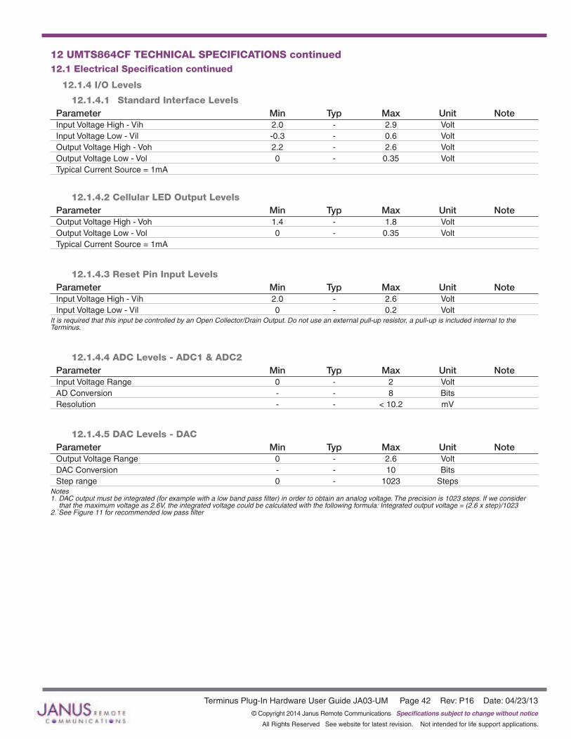
Terminus Plug-In Hardware User Guide JA03-UM Page 42 Rev: P16 Date: 04/23/13© Copyright 2014 Janus Remote Communications Specifications subject to change without notice
All Rights Reserved See website for latest revision. Not intended for life support applications.
12 UMTS864CF TECHNICAL SPECIFICATIONS continued12.1 Electrical Specification continued
12.1.4 I/O Levels
12.1.4.1 Standard Interface LevelsParameter Min Typ Max Unit NoteInput Voltage High - Vih 2.0 - 2.9 Volt Input Voltage Low - Vil -0.3 - 0.6 Volt Output Voltage High - Voh 2.2 - 2.6 Volt Output Voltage Low - Vol 0 - 0.35 Volt Typical Current Source = 1mA
12.1.4.2 Cellular LED Output LevelsParameter Min Typ Max Unit NoteOutput Voltage High - Voh 1.4 - 1.8 Volt Output Voltage Low - Vol 0 - 0.35 Volt Typical Current Source = 1mA
12.1.4.3 Reset Pin Input Levels Parameter Min Typ Max Unit NoteInput Voltage High - Vih 2.0 - 2.6 Volt Input Voltage Low - Vil 0 - 0.2 Volt
It is required that this input be controlled by an Open Collector/Drain Output. Do not use an external pull-up resistor, a pull-up is included internal to the Terminus.
12.1.4.4 ADC Levels - ADC1 & ADC2Parameter Min Typ Max Unit NoteInput Voltage Range 0 - 2 Volt AD Conversion - - 8 Bits Resolution - - < 10.2 mV
12.1.4.5 DAC Levels - DACParameter Min Typ Max Unit NoteOutput Voltage Range 0 - 2.6 Volt DAC Conversion - - 10 Bits Step range 0 - 1023 Steps
Notes 1. DAC output must be integrated (for example with a low band pass filter) in order to obtain an analog voltage. The precision is 1023 steps. If we consider that the maximum voltage as 2.6V, the integrated voltage could be calculated with the following formula: Integrated output voltage = (2.6 x step)/1023 2.`See Figure 11 for recommended low pass filter
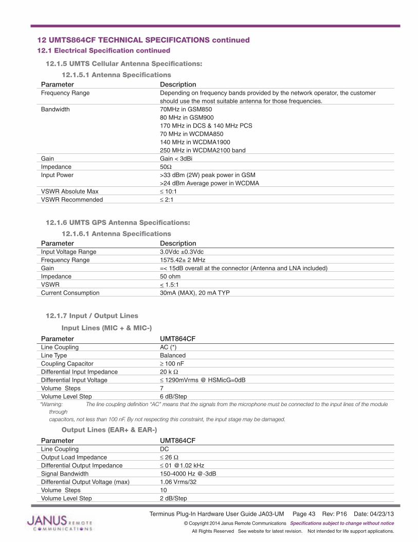
Terminus Plug-In Hardware User Guide JA03-UM Page 43 Rev: P16 Date: 04/23/13© Copyright 2014 Janus Remote Communications Specifications subject to change without notice
All Rights Reserved See website for latest revision. Not intended for life support applications.
12.1.5 UMTS Cellular Antenna Specifications:
12.1.5.1 Antenna SpecificationsParameter DescriptionFrequency Range Depending on frequency bands provided by the network operator, the customer should use the most suitable antenna for those frequencies.Bandwidth 70MHz in GSM850 80 MHz in GSM900 170 MHz in DCS & 140 MHz PCS 70 MHz in WCDMA850 140 MHz in WCDMA1900 250 MHz in WCDMA2100 bandGain Gain < 3dBiImpedance 50WInput Power >33 dBm (2W) peak power in GSM >24 dBm Average power in WCDMAVSWR Absolute Max ≤ 10:1VSWR Recommended ≤ 2:1
12.1.6 UMTS GPS Antenna Specifications:
12.1.6.1 Antenna SpecificationsParameter DescriptionInput Voltage Range 3.0Vdc ±0.3VdcFrequency Range 1575.42± 2 MHzGain =< 15dB overall at the connector (Antenna and LNA included)Impedance 50 ohmVSWR < 1.5:1 Current Consumption 30mA (MAX), 20 mA TYP
12.1.7 Input / Output Lines
Input Lines (MIC + & MIC-)
Parameter UMT864CFLine Coupling AC (*)Line Type BalancedCoupling Capacitor ≥ 100 nFDifferential Input Impedance 20 k WDifferential Input Voltage ≤ 1290mVrms @ HSMicG=0dBVolume Steps 7Volume Level Step 6 dB/Step*Warning: Thelinecouplingdefinition“AC”meansthatthesignalsfromthemicrophonemustbeconnectedtotheinputlinesofthemodule
throughcapacitors,notlessthan100nF.Bynotrespectingthisconstraint,theinputstagemaybedamaged.
Output Lines (EAR+ & EAR-)
Parameter UMT864CFLine Coupling DCOutput Load Impedance ≤ 26 WDifferential Output Impedance ≤ 01 @1.02 kHzSignal Bandwidth 150-4000 Hz @-3dBDifferential Output Voltage (max) 1.06 Vrms/32Volume Steps 10Volume Level Step 2 dB/Step
12 UMTS864CF TECHNICAL SPECIFICATIONS continued12.1 Electrical Specification continued
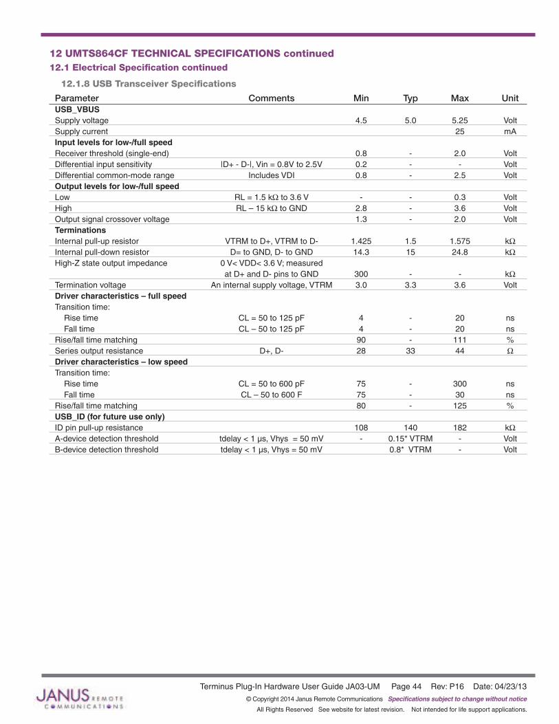
Terminus Plug-In Hardware User Guide JA03-UM Page 44 Rev: P16 Date: 04/23/13© Copyright 2014 Janus Remote Communications Specifications subject to change without notice
All Rights Reserved See website for latest revision. Not intended for life support applications.
12 UMTS864CF TECHNICAL SPECIFICATIONS continued12.1 Electrical Specification continued
12.1.8 USB Transceiver Specifications
Parameter Comments Min Typ Max UnitUSB_VBUS Supply voltage 4.5 5.0 5.25 VoltSupply current 25 mAInput levels for low-/full speed Receiver threshold (single-end) 0.8 - 2.0 VoltDifferential input sensitivity |D+ - D-|, Vin = 0.8V to 2.5V 0.2 - - VoltDifferential common-mode range Includes VDI 0.8 - 2.5 VoltOutput levels for low-/full speed Low RL = 1.5 kW to 3.6 V - - 0.3 VoltHigh RL – 15 kW to GND 2.8 - 3.6 VoltOutput signal crossover voltage 1.3 - 2.0 VoltTerminations Internal pull-up resistor VTRM to D+, VTRM to D- 1.425 1.5 1.575 kWInternal pull-down resistor D= to GND, D- to GND 14.3 15 24.8 kWHigh-Z state output impedance 0 V< VDD< 3.6 V; measured at D+ and D- pins to GND 300 - - kWTermination voltage An internal supply voltage, VTRM 3.0 3.3 3.6 VoltDriver characteristics – full speed Transition time: Rise time CL = 50 to 125 pF 4 - 20 ns Fall time CL – 50 to 125 pF 4 - 20 nsRise/fall time matching 90 - 111 %Series output resistance D+, D- 28 33 44 WDriver characteristics – low speed Transition time: Rise time CL = 50 to 600 pF 75 - 300 ns Fall time CL – 50 to 600 F 75 - 30 nsRise/fall time matching 80 - 125 %USB_ID (for future use only) ID pin pull-up resistance 108 140 182 kWA-device detection threshold tdelay < 1 µs, Vhys = 50 mV - 0.15* VTRM - VoltB-device detection threshold tdelay < 1 µs, Vhys = 50 mV 0.8* VTRM - Volt
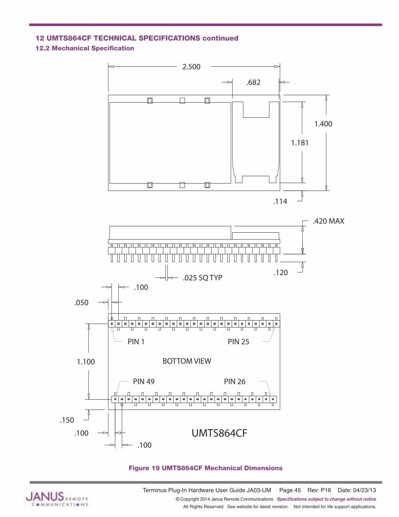
Terminus Plug-In Hardware User Guide JA03-UM Page 45 Rev: P16 Date: 04/23/13© Copyright 2014 Janus Remote Communications Specifications subject to change without notice
All Rights Reserved See website for latest revision. Not intended for life support applications.
.682
.100
.100
.150
1.100
.050
.100
2.500
.120
.420 MAX
1.181
.114
1.400
.025 SQ TYP
UMTS864CF
PIN 25PIN 1
PIN 49
BOTTOM VIEW
PIN 26
12 UMTS864CF TECHNICAL SPECIFICATIONS continued12.2 Mechanical Specification
Figure 19 UMTS864CF Mechanical Dimensions

Terminus Plug-In Hardware User Guide JA03-UM Page 46 Rev: P16 Date: 04/23/13© Copyright 2014 Janus Remote Communications Specifications subject to change without notice
All Rights Reserved See website for latest revision. Not intended for life support applications.
12 UMTS864CF TECHNICAL SPECIFICATIONS continued12.3 Setting Up a Terminal Emulator for Use With the UMTS864CF Terminus
12.3.1 Set UpTo interface with the module, connect the serial interface to a PC and use a terminal emulation program such as Microsoft® Hyperterminal. Set the interface parameters as follows:
• Baud Rate: 115.2 kbps• Bits: 8• Stop Bits: 1• Parity: None• Hardware Handshaking: Yes
12.3.1.1 Test the Emulator Set Up• Enter AT<cr> from terminal and wait for OK
Note that Autobaud is not supported on the UMTS864CF Terminus. If you are utilizing the serial interface and you wish to change the baud rate on the module, you must use AT+IPR. You must also change the rate in the host UART (i.e. HyperTerminal) to match the new baud rate. If these do not match you will not be able to send AT commands to the module through the serial port. The Terminus is by default set to 115.2 kbps.
12.3.1.2 Verify Your Terminal and Firmware Version• Enter AT+CGMM and wait for the response
The response will be the Telit module’s model number without a command echo.• Enter AT+CGMR and wait for the response
The response will be the Telit module’s current firmware without a command echo.
Please confirm your model and firmware with the one listed in section 2.1
12.3.2 Powering ON/OFF
12.3.2.1 Turn the module ON through the following method:• Pull ON/OFF signal (Pin 19) to ground for two (2) seconds, then release.
The Terminus module is fully operational after 4 seconds. Logging onto a network may take longer than this and is outside the control of the Terminus.
12.3.2.2 There are two ways to switch OFF the module as described below.• Use the appropriate AT command (AT#SHDN)• Pull ON/OFF signal (Pin 19) to ground for two (2) seconds, then release.

Terminus Plug-In Hardware User Guide JA03-UM Page 47 Rev: P16 Date: 04/23/13© Copyright 2014 Janus Remote Communications Specifications subject to change without notice
All Rights Reserved See website for latest revision. Not intended for life support applications.
12.3 UMTS864CF GETTING STARTED continued12.3 Setting Up a Terminal Emulator for Use With the UMTS864CF Terminus continued
12.3.3 Setting Up Service – Network Settings
11.3.3.1 Set Up The network settings for the Terminus will vary depending on the cellular carrier you are using. Below are two of the North American Cases for these settings.
For T-mobile® & MNVO (Raco®, Sensor Logic®, Nexaira® Jasper Wireless®) enter:
• AT#SELINT=2 //use of most recent AT command set • AT#STIA=2,10 or AT#STIA=1 // enable SAT – SIM Application Tool-Kit • AT#BND=3 // default bands to 850/1900 • AT#AUTOBND=1 // enable Quad band system selection • AT#PLMNMODE=1 // enable EONS (enhanced operator naming scheme) • AT&P0 // save profile • AT&W0 // save setting • AT#ENS=0
For AT&T/Cingular® & MNVO (Kore®, Aeris®, nPhase®) enter:
• AT#SELINT=2 //use of most recent AT command set • AT#ENS=1 // AT&T/Cingular configuration (SAT, BND, AUTONBND, PLMNMODE, plus Cingular® specific ENS
requirements)
If Terminus is being used in a different country or with a different carrier please refer to Telit AT command refer¬ence document regarding the use of the AT#BND command to set the proper frequency band).
Important: After entering either of the sets of settings above power the Terminus OFF and then ON. It is now ready for use.
12.3.3.2 Check Network Status (assuming you have a valid SIM card installed)Enter AT+CREG? <cr> And wait for response.
Response will be +CREG:0,1 or +CREG: 0,5 meaning the device is registered to the home network or roaming, respectively. If response is different than this, please refer to the Telit AT command reference document for more information.
12.3.3.3 Check Signal Quality Enter AT+CSQ<cr> And wait for response +CSQ:<rssi>,<ber>
<rssi> Signal Strength 99 Not known or not detectable 0-31 dBm = (rssi * 2) –113
Example: A result of 31 indicates -51dBm or greater.
An rssi value of >=10 in typical applications is fine and you will usually see about 12-20 in normal to good signal, but note that worst case it can be lower, still register and perform normal functions.
12.3.4 Making a Voice Call
12.3.4.1 Set Up Voice call mode allows you to use a telephone handset to communicate with a properly equipped subscriber unit.
• Set the call mode to voice Enter AT+FCLASS=8<cr> and wait for response OK
• Set the audio path of the Terminus Enter AT#CAP=0
• Dial the phone number Enter ATD <8885551234>; <cr>
• To disconnect the call enter ATH<cr>
Note that the current AT&T approval for the UMTS864CF does not allow voice calls.

Terminus Plug-In Hardware User Guide JA03-UM Page 48 Rev: P16 Date: 04/23/13© Copyright 2014 Janus Remote Communications Specifications subject to change without notice
All Rights Reserved See website for latest revision. Not intended for life support applications.
12.3 UMTS864CF GETTING STARTED continued12.3 Setting Up a Terminal Emulator for Use With the UMTS864CF Terminus continued
12.3.5 Sending an SMS
12.3.5.1 Set Up SMS (Select Message Service) mode allows you to send a text message (max 160 characters) to a SMS capable subscriber unit.
• Set the SMS mode to text. This must be entered every power cycle. AT+CMGF=1<cr>
• To enter the receiving subscriber unit phone number and message enter: AT+CMGS=”8885551234” Wait for response”>” then enter message text Enter “ctrl z” <cr> to end the message
12.3.6 Making a GPRS Data Call
12.3.6.1 Set Up GPRS is a data service that uses Packet Data Protocol (PDP).
• Set up the PDP context parameters Enter AT+CGDCONT=1, “IP”, “APN”, “0.0.0.0”,0,0<cr> Where APN is specific to the service provider being used.
• Set the minimum Quality of Service profile Enter AT+CGQMIN=1,0,0,0,0,0
• Set up the desired Quality of Service profile Enter AT+CGQREQ=1,0,0,3,0,0
• Activate the PDP context Enter AT#SGACT=1,1,”v”, “p” Where v is your user ID and p is your password. If these are not set replace with “”,””
• Open the socket connection Enter AT#SD=1,0,IPP,IPA,0,0,0 Look for response “CONNECT”. This opens a remote connection via socket IPP = the remote host port of the server you are trying to connect to (0 to 65535). IPA = the IP address of the server you are trying to connect to in the format: “xxx.xxx.xxx.xxx”
• At this point a data session is active and data can be sent from the Terminus to the remote device and visa versa. • To exit the data session and return to command mode, send the characters”+++” and wait for the OK response • Enter AT#SH=1 to close the socket
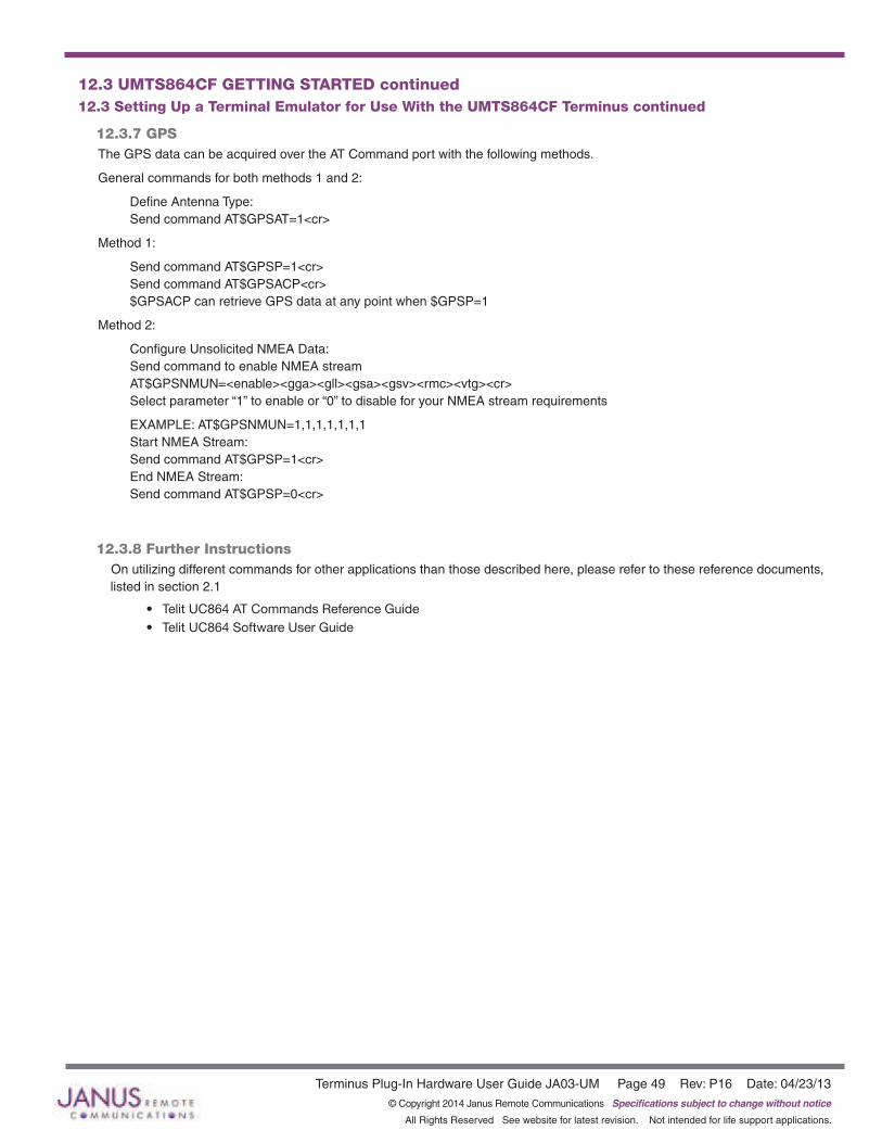
Terminus Plug-In Hardware User Guide JA03-UM Page 49 Rev: P16 Date: 04/23/13© Copyright 2014 Janus Remote Communications Specifications subject to change without notice
All Rights Reserved See website for latest revision. Not intended for life support applications.
12.3 UMTS864CF GETTING STARTED continued12.3 Setting Up a Terminal Emulator for Use With the UMTS864CF Terminus continued
12.3.7 GPSThe GPS data can be acquired over the AT Command port with the following methods.
General commands for both methods 1 and 2:
Define Antenna Type: Send command AT$GPSAT=1<cr>
Method 1:
Send command AT$GPSP=1<cr> Send command AT$GPSACP<cr> $GPSACP can retrieve GPS data at any point when $GPSP=1
Method 2:
Configure Unsolicited NMEA Data: Send command to enable NMEA stream AT$GPSNMUN=<enable><gga><gll><gsa><gsv><rmc><vtg><cr> Select parameter “1” to enable or “0” to disable for your NMEA stream requirements
EXAMPLE: AT$GPSNMUN=1,1,1,1,1,1,1 Start NMEA Stream: Send command AT$GPSP=1<cr> End NMEA Stream: Send command AT$GPSP=0<cr>
12.3.8 Further Instructions On utilizing different commands for other applications than those described here, please refer to these reference documents, listed in section 2.1
• Telit UC864 AT Commands Reference Guide• Telit UC864 Software User Guide

Terminus Plug-In Hardware User Guide JA03-UM Page 50 Rev: P16 Date: 04/23/13© Copyright 2014 Janus Remote Communications Specifications subject to change without notice
All Rights Reserved See website for latest revision. Not intended for life support applications.
13 HSPA910CF TECHNICAL SPECIFICATIONS13.1 Electrical Specification
13.1.1 Absolute Maximum Ratings
Parameter Min Typ Max Unit Note VIN (DIGITAL INPUTS 2.85V CMOS) -0.5 - 3.35 Volt VIN (DIGITAL INPUTS 1.8V CMOS) -0.3 - 3.1 VoltStorage Temperature -40 - 85 °C Supply (+) referenced to Supply (-) 0 - 6 Volt
Operation of the device at these or any other conditions beyond those listed under Recommended Operating Conditions is not implied. Exposure to Absolute Maximum Rating conditions for extended periods of time may affect device reliability.
13.1.2 Recommended Operating Conditions
Parameter Min Typ Max Unit Note Temperature -40 - 85 °C Supply (+) referenced to Supply (-) 4.75 5.0 5.25 Volt VAUX Output - 2.85 - Volt VAUX Current - - 100 mA
13.1.3 Power Supply
Mode Average (mA) Mode Description POWERED DOWN Terminal Disabled < 15µA Terminal disabled (ENABLE SUPPLY = 0)Cellular Radio Off 0.4 Cellular module powered but switched off via ON_OFF pin (PWRMON=0) IDLE MODEMode Average (mA) Mode Description
GPS OFF
AT+CFUN=1 WCDMA 13.8 Idle, no call in progress. Full functionality of the module GSM 13.9AT+CFUN=4 WCDMA 14.4 Disabled TX and RX; module is not registered on the network GSM 14.4AT+CFUN=5 WCDMA 3.4 CFUN=5 full functionality with power saving; Module registered on GSM 3.3 the network can receive incoming call sand SMSAT+CFUN=7 WCDMA 10.0 CFUN=5 full functionality with power saving; Module registered on GSM 9.2 the network can receive incoming call sand SMSWCDMA/HSDPA GPS OFF in HSPA910CF WCDMA Voice TBD voice channel WCDMA data 130.2 data channelGSM GSM Voice TBD GSM voice channel GPRS Class 12 129.3 GPRS data channel
GPS ON AT+CFUN=1 WCDMA 35.5 GSM 37.2 Idle, no call in progress. Full functionality of the moduleAT+CFUN=4 WCDMA 36.8 Disabled TX and RX; module is not registered on the network GSM 37.6AT+CFUN=5 WCDMA 28.9 Disabled TX and RX; module is not registered on the network GSM 30.0AT+CFUN=7 WCDMA 33.8 Disabled TX and RX; module is not registered on the network GSM 34.3WCDMA/HSDPA WCDMA Voice TBD WCDMA voice channel WCDMA Data 156 WCDMA data channelGSM GSM Voice TBD GSM voice channel GPRS/EDGE Class 12 152 GPRS data channel
* except external active GPS antenna. * Data taken with USB disconnected.

Terminus Plug-In Hardware User Guide JA03-UM Page 51 Rev: P16 Date: 04/23/13© Copyright 2014 Janus Remote Communications Specifications subject to change without notice
All Rights Reserved See website for latest revision. Not intended for life support applications.
13 HSPA910CF TECHNICAL SPECIFICATIONS continued13.1 Electrical Specification continued
13.1.4 I/O Levels
13.1.4.1 1.8v Standard Interface Levels (DVI, I2C, GPS LED)Parameter Min Typ Max Unit NoteInput Voltage High - Vih 1.5 - 1.9 Volt Input Voltage Low - Vil 0 - 0.35 Volt Output Voltage High - Voh 1.6 - 1.9 Volt Output Voltage Low - Vol 0 - 0.2 Volt Typical Current Source/Sink = 100uA/1uA
13.1.4.2 2.85v Standard Interface Levels (UART, GPIO)Parameter Min Typ Max Unit NoteInput Voltage High - Vih 1.85 - 2.85 Volt Input Voltage Low - Vil 0 - 0.99 Volt Output Voltage High - Voh 2.45 - 2.85 Volt Output Voltage Low - Vol 0 - 0.4 Volt Typical Current Source = 100uA/1uA
13.1.4.3 Cellular LED Output LevelsParameter Min Typ Max Unit NoteOutput Voltage High - Voh 1.6 - 1.9 Volt Output Voltage Low - Vol 0 - 0.2 Volt Typical Current Source = 100uA
13.1.4.4 ADC Input LevelsParameter Min Typ Max Unit NoteInput Voltage Range 0 - 1.2 VoltAD Conversion - - 10 BitsInput Resistance 1M - - OhmInput Capacitance - 1 - pF
13.1.4.5 Reset Pin Input Levels Parameter Min Typ Max Unit NoteInput Voltage High - Vih 1.5 - 1.9 Volt Input Voltage Low - Vil 0 - 0.35 Volt
It is required that this input be controlled by an Open Collector/Drain Output. Do not use an external pull-up resistor, a pull-up is included internal to the Terminus.
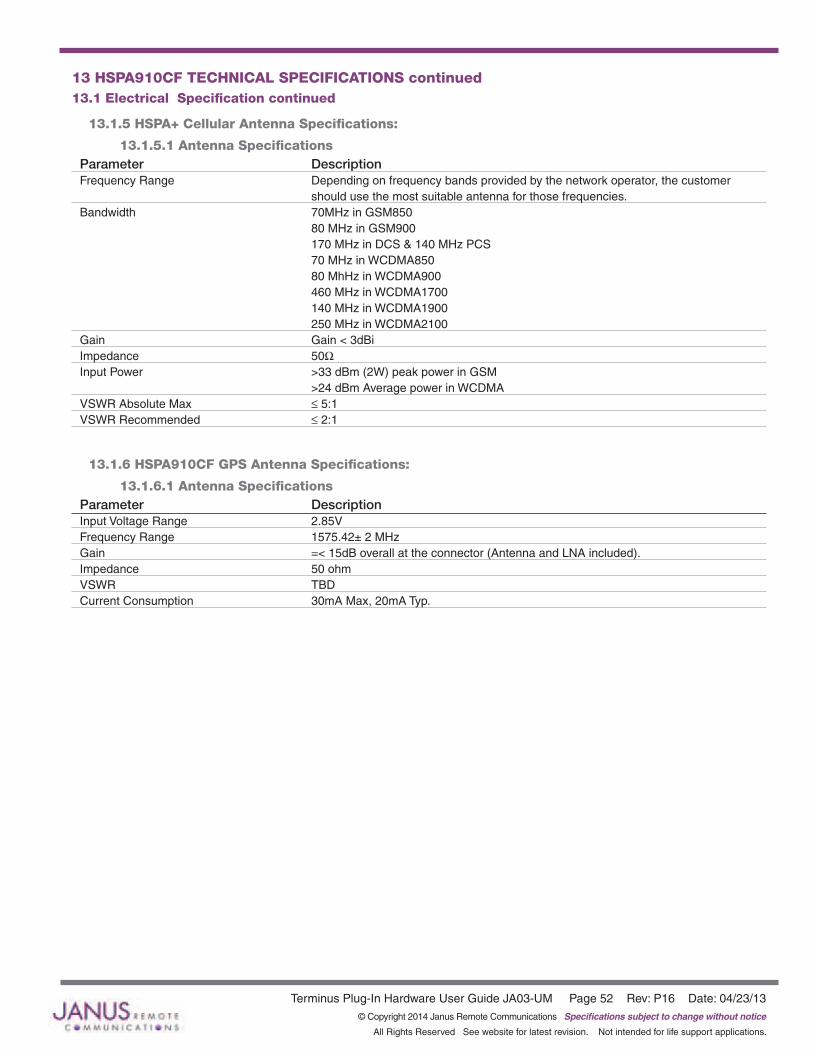
Terminus Plug-In Hardware User Guide JA03-UM Page 52 Rev: P16 Date: 04/23/13© Copyright 2014 Janus Remote Communications Specifications subject to change without notice
All Rights Reserved See website for latest revision. Not intended for life support applications.
13.1.5 HSPA+ Cellular Antenna Specifications:
13.1.5.1 Antenna SpecificationsParameter DescriptionFrequency Range Depending on frequency bands provided by the network operator, the customer should use the most suitable antenna for those frequencies.Bandwidth 70MHz in GSM850 80 MHz in GSM900 170 MHz in DCS & 140 MHz PCS 70 MHz in WCDMA850 80 MhHz in WCDMA900 460 MHz in WCDMA1700 140 MHz in WCDMA1900 250 MHz in WCDMA2100Gain Gain < 3dBiImpedance 50WInput Power >33 dBm (2W) peak power in GSM >24 dBm Average power in WCDMAVSWR Absolute Max ≤ 5:1VSWR Recommended ≤ 2:1
13.1.6 HSPA910CF GPS Antenna Specifications:
13.1.6.1 Antenna SpecificationsParameter DescriptionInput Voltage Range 2.85VFrequency Range 1575.42± 2 MHzGain =< 15dB overall at the connector (Antenna and LNA included).Impedance 50 ohmVSWR TBDCurrent Consumption 30mA Max, 20mA Typ.
13 HSPA910CF TECHNICAL SPECIFICATIONS continued13.1 Electrical Specification continued
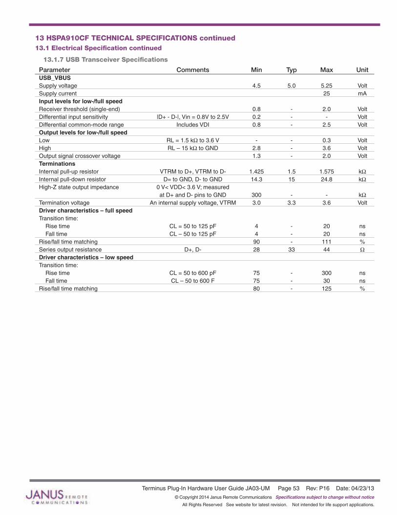
Terminus Plug-In Hardware User Guide JA03-UM Page 53 Rev: P16 Date: 04/23/13© Copyright 2014 Janus Remote Communications Specifications subject to change without notice
All Rights Reserved See website for latest revision. Not intended for life support applications.
13 HSPA910CF TECHNICAL SPECIFICATIONS continued13.1 Electrical Specification continued
13.1.7 USB Transceiver Specifications
Parameter Comments Min Typ Max UnitUSB_VBUS Supply voltage 4.5 5.0 5.25 VoltSupply current 25 mAInput levels for low-/full speed Receiver threshold (single-end) 0.8 - 2.0 VoltDifferential input sensitivity |D+ - D-|, Vin = 0.8V to 2.5V 0.2 - - VoltDifferential common-mode range Includes VDI 0.8 - 2.5 VoltOutput levels for low-/full speed Low RL = 1.5 kW to 3.6 V - - 0.3 VoltHigh RL – 15 kW to GND 2.8 - 3.6 VoltOutput signal crossover voltage 1.3 - 2.0 VoltTerminations Internal pull-up resistor VTRM to D+, VTRM to D- 1.425 1.5 1.575 kWInternal pull-down resistor D= to GND, D- to GND 14.3 15 24.8 kWHigh-Z state output impedance 0 V< VDD< 3.6 V; measured at D+ and D- pins to GND 300 - - kWTermination voltage An internal supply voltage, VTRM 3.0 3.3 3.6 VoltDriver characteristics – full speed Transition time: Rise time CL = 50 to 125 pF 4 - 20 ns Fall time CL – 50 to 125 pF 4 - 20 nsRise/fall time matching 90 - 111 %Series output resistance D+, D- 28 33 44 WDriver characteristics – low speed Transition time: Rise time CL = 50 to 600 pF 75 - 300 ns Fall time CL – 50 to 600 F 75 - 30 nsRise/fall time matching 80 - 125 %

Terminus Plug-In Hardware User Guide JA03-UM Page 54 Rev: P16 Date: 04/23/13© Copyright 2014 Janus Remote Communications Specifications subject to change without notice
All Rights Reserved See website for latest revision. Not intended for life support applications.
13 HSPA910CF TECHNICAL SPECIFICATIONS continued13.2 Mechanical Specification
Figure 20 HSPA910CF Mechanical Dimensions
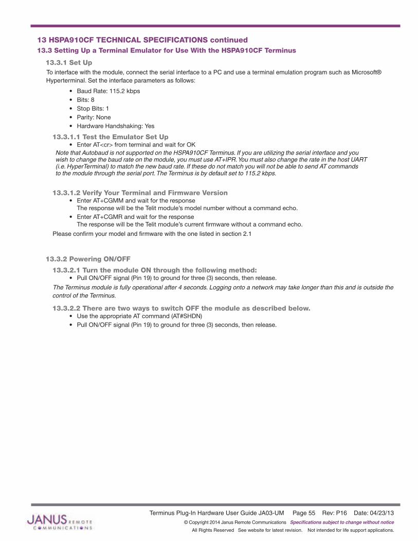
Terminus Plug-In Hardware User Guide JA03-UM Page 55 Rev: P16 Date: 04/23/13© Copyright 2014 Janus Remote Communications Specifications subject to change without notice
All Rights Reserved See website for latest revision. Not intended for life support applications.
13 HSPA910CF TECHNICAL SPECIFICATIONS continued13.3 Setting Up a Terminal Emulator for Use With the HSPA910CF Terminus
13.3.1 Set UpTo interface with the module, connect the serial interface to a PC and use a terminal emulation program such as Microsoft® Hyperterminal. Set the interface parameters as follows:
• Baud Rate: 115.2 kbps• Bits: 8• Stop Bits: 1• Parity: None• Hardware Handshaking: Yes
13.3.1.1 Test the Emulator Set Up• Enter AT<cr> from terminal and wait for OK
Note that Autobaud is not supported on the HSPA910CF Terminus. If you are utilizing the serial interface and you wish to change the baud rate on the module, you must use AT+IPR. You must also change the rate in the host UART (i.e. HyperTerminal) to match the new baud rate. If these do not match you will not be able to send AT commands to the module through the serial port. The Terminus is by default set to 115.2 kbps.
13.3.1.2 Verify Your Terminal and Firmware Version• Enter AT+CGMM and wait for the response
The response will be the Telit module’s model number without a command echo.• Enter AT+CGMR and wait for the response
The response will be the Telit module’s current firmware without a command echo.
Please confirm your model and firmware with the one listed in section 2.1
13.3.2 Powering ON/OFF
13.3.2.1 Turn the module ON through the following method:• Pull ON/OFF signal (Pin 19) to ground for three (3) seconds, then release.
The Terminus module is fully operational after 4 seconds. Logging onto a network may take longer than this and is outside the control of the Terminus.
13.3.2.2 There are two ways to switch OFF the module as described below.• Use the appropriate AT command (AT#SHDN)• Pull ON/OFF signal (Pin 19) to ground for three (3) seconds, then release.
Terminus Plug-In Hardware User Guide JA03-UM Page 56 Rev: P16 Date: 04/23/13© Copyright 2014 Janus Remote Communications Specifications subject to change without notice
All Rights Reserved See website for latest revision. Not intended for life support applications.
13.3 HSPA910CF GETTING STARTED continued13.3 Setting Up a Terminal Emulator for Use With the HSPA910CF Terminus continued
13.3.3 Setting Up Service – Network Settings
13.3.3.1 Set Up The network settings for the Terminus will vary depending on the cellular carrier you are using. Below are two of the North American Cases for these settings.
For T-mobile® & MNVO (Raco®, Sensor Logic®, Nexaira® Jasper Wireless®) enter:
• AT#SELINT=2 //use of most recent AT command set • AT#STIA=2,10 or AT#STIA=1 // enable SAT – SIM Application Tool-Kit • AT#BND=3,3 // default bands to 850/1900/2100• AT#AUTOBND=1 // enable Quad band system selection • AT&P0 // save profile • AT&W0 // save setting • AT#ENS=0
For AT&T/Cingular® & MNVO (Kore®, Aeris®, nPhase®) enter:
• AT#SELINT=2 //use of most recent AT command set • AT#ENS=1 // AT&T/Cingular configuration (SAT, BND, AUTONBND, PLMNMODE, plus Cingular® specific ENS
requirements)
If Terminus is being used in a different country or with a different carrier please refer to Telit AT command refer¬ence document regarding the use of the AT#BND command to set the proper frequency band).
Important: After entering either of the sets of settings above power the Terminus OFF and then ON. It is now ready for use.
13.3.3.2 Check Network Status (assuming you have a valid SIM card installed)Enter AT+CREG? <cr> And wait for response.
Response will be +CREG:0,1 or +CREG: 0,5 meaning the device is registered to the home network or roaming, respectively. If response is different than this, please refer to the Telit AT command reference document for more information.
13.3.3.3 Check Signal Quality Enter AT+CSQ<cr> And wait for response +CSQ:<rssi>,<ber>
<rssi> Signal Strength 99 Not known or not detectable 0-31 dBm = (rssi * 2) –113
Example: A result of 31 indicates -51dBm or greater.
An rssi value of >=10 in typical applications is fine and you will usually see about 12-20 in normal to good signal, but note that worst case it can be lower, still register and perform normal functions.
13.3.4 Making a Voice Call
13.3.4.1 Set Up Voice call mode allows you to use a telephone handset to communicate with a properly equipped subscriber unit.
• Set the call mode to voice Enter AT+FCLASS=8<cr> and wait for response OK
• Dial the phone number Enter ATD <8885551234>; <cr>
• To disconnect the call enter ATH<cr>
Terminus Plug-In Hardware User Guide JA03-UM Page 57 Rev: P16 Date: 04/23/13© Copyright 2014 Janus Remote Communications Specifications subject to change without notice
All Rights Reserved See website for latest revision. Not intended for life support applications.
13.3 HSPA910CF GETTING STARTED continued13.3 Setting Up a Terminal Emulator for Use With the HSPA910CF Terminus continued
13.3.5 Sending an SMS
13.3.5.1 Set Up SMS (Select Message Service) mode allows you to send a text message (max 160 characters) to a SMS capable subscriber unit.
• Set the SMS mode to text. This must be entered every power cycle. AT+CMGF=1<cr>
• To enter the receiving subscriber unit phone number and message enter: AT+CMGS=”8885551234” Wait for response”>” then enter message text Enter “ctrl z” <cr> to end the message
13.3.6 Making a GPRS Data Call
13.3.6.1 Set Up GPRS is a data service that uses Packet Data Protocol (PDP).
• Set up the PDP context parameters Enter AT+CGDCONT=1, “IP”, “APN”, “0.0.0.0”,0,0<cr> Where APN is specific to the service provider being used.
• Activate the PDP context Enter AT#SGACT=1,1,”v”, “p” Where v is your user ID and p is your password. If these are not set replace with “”,””
• Open the socket connection Enter AT#SD=1,0,IPP,IPA,0,0,0 Look for response “CONNECT”. This opens a remote connection via socket IPP = the remote host port of the server you are trying to connect to. (0 to 65535) IPA = the IP address of the server hyou are trying to connect to in the format: “xxx.xxx.xxx.xxx”
• At this point a data session is active and data can be sent from the Terminus to the remote device and visa versa. • To exit the data session and return to command mode, send the characters”+++” and wait for the OK response • Enter AT#SH=1 to close the socket

Terminus Plug-In Hardware User Guide JA03-UM Page 58 Rev: P16 Date: 04/23/13© Copyright 2014 Janus Remote Communications Specifications subject to change without notice
All Rights Reserved See website for latest revision. Not intended for life support applications.
13.3 HSPA910CF GETTING STARTED continued13.3 Setting Up a Terminal Emulator for Use With the HSPA910CF Terminus continued
13.3.7 GPSThe GPS data can be acquired over the AT Command port with the following methods.
Method 1:
Send command AT$GPSP=1<cr> Send command AT$GPSACP<cr> $GPSACP can retrieve GPS data at any point when $GPSP=1
Method 2:
Configure Unsolicited NMEA Data: Send command to enable NMEA stream AT$GPSNMUN=<enable><gga><gll><gsa><gsv><rmc><vtg><cr> Select parameter “1” to enable or “0” to disable for your NMEA stream requirements
EXAMPLE: AT$GPSNMUN=1,1,1,1,1,1,1 Send command AT$GPSP=1<cr> End NMEA Stream: Send command AT$GPSP=0<cr>
13.3.8 Further Instructions On utilizing different commands for other applications than those described here, please refer to these reference documents, listed in section 2.1
• Telit HE910 AT Commands Reference Guide• Telit HE910 Software User Guide

Terminus Plug-In Hardware User Guide JA03-UM Page 59 Rev: P16 Date: 04/23/13© Copyright 2014 Janus Remote Communications Specifications subject to change without notice
All Rights Reserved See website for latest revision. Not intended for life support applications.
14 EVDO910CF TECHNICAL SPECIFICATIONS14.1 Electrical Specification
14.1.1 Absolute Maximum Ratings
Parameter Min Typ Max Unit Note VIN (DIGITAL INPUTS 2.85V CMOS) -0.5 - 3.35 Volt VIN (DIGITAL INPUTS 1.8V CMOS) -0.3 - 3.1 VoltStorage Temperature -40 - 85 °C Supply (+) referenced to Supply (-) 0 - 6 Volt
Operation of the device at these or any other conditions beyond those listed under Recommended Operating Conditions is not implied. Exposure to Absolute Maximum Rating conditions for extended periods of time may affect device reliability.
14.1.2 Recommended Operating Conditions
Parameter Min Typ Max Unit Note Temperature -30 - 80 °C Supply (+) referenced to Supply (-) 4.75 5.0 5.25 Volt VAUX Output - 2.85 - Volt VAUX Current - - 100 mA
14.1.3 Power Supply
Mode Average (mA) Mode Description
POWERED DOWN Terminal Disabled < 15µA Terminal disabled (ENABLE SUPPLY = 0)Cellular Radio Off 0.4 Cellular module powered but switched off via ON_OFF pin (PWRMON=0) IDLE MODE
Mode Average (mA) Mode Description
GPS OFF
AT+CFUN=1 13 Idle, no call in progress. Full functionality of the moduleAT+CFUN=4 20 Disabled TX and RX; module is not registered on the networkAT+CFUN=5 3 CFUN=5 full functionality with power saving; Module registered on the network can receive incoming call sand SMSAT+CFUN=7 TBD CFUN=5 full functionality with power saving; Module registered on the network can receive incoming call sand SMSEV-DO Voice TBD Voice channel Data 570 Data channelCDMA Voice TBD Voice channel Data 590 Data channel
GPS ON AT+CFUN=1 60 Idle, no call in progress. Full functionality of the moduleAT+CFUN=4 75 Disabled TX and RX; module is not registered on the networkAT+CFUN=5 57 Disabled TX and RX; module is not registered on the network AT+CFUN=7 TBD Disabled TX and RX; module is not registered on the networkEV-DO Voice TBD Voice channel Data 640 Data channelCDMA Voice TBD Voice channel Data 640 Data channel
* except external active GPS antenna. * Data taken with USB disconnected.
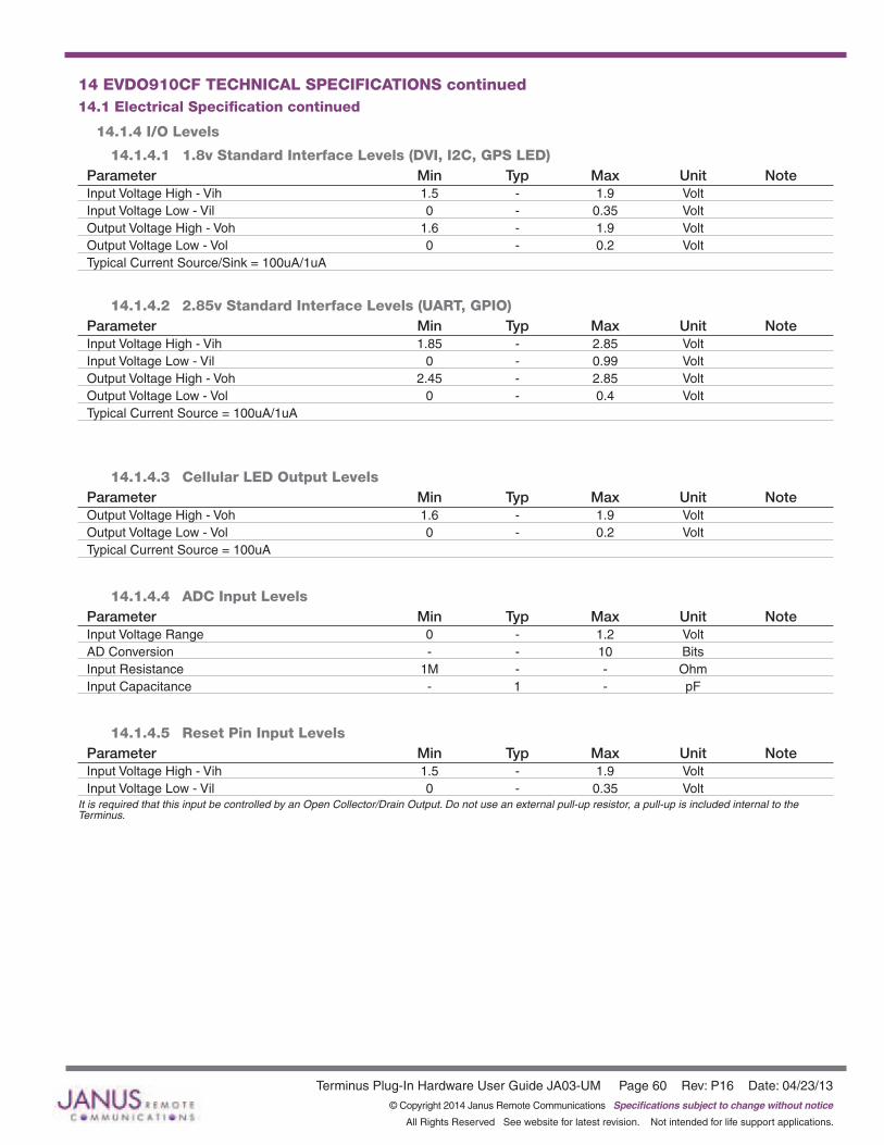
Terminus Plug-In Hardware User Guide JA03-UM Page 60 Rev: P16 Date: 04/23/13© Copyright 2014 Janus Remote Communications Specifications subject to change without notice
All Rights Reserved See website for latest revision. Not intended for life support applications.
14 EVDO910CF TECHNICAL SPECIFICATIONS continued14.1 Electrical Specification continued
14.1.4 I/O Levels
14.1.4.1 1.8v Standard Interface Levels (DVI, I2C, GPS LED)Parameter Min Typ Max Unit NoteInput Voltage High - Vih 1.5 - 1.9 Volt Input Voltage Low - Vil 0 - 0.35 Volt Output Voltage High - Voh 1.6 - 1.9 Volt Output Voltage Low - Vol 0 - 0.2 Volt Typical Current Source/Sink = 100uA/1uA
14.1.4.2 2.85v Standard Interface Levels (UART, GPIO)Parameter Min Typ Max Unit NoteInput Voltage High - Vih 1.85 - 2.85 Volt Input Voltage Low - Vil 0 - 0.99 Volt Output Voltage High - Voh 2.45 - 2.85 Volt Output Voltage Low - Vol 0 - 0.4 Volt Typical Current Source = 100uA/1uA
14.1.4.3 Cellular LED Output LevelsParameter Min Typ Max Unit NoteOutput Voltage High - Voh 1.6 - 1.9 Volt Output Voltage Low - Vol 0 - 0.2 Volt Typical Current Source = 100uA
14.1.4.4 ADC Input LevelsParameter Min Typ Max Unit NoteInput Voltage Range 0 - 1.2 VoltAD Conversion - - 10 BitsInput Resistance 1M - - OhmInput Capacitance - 1 - pF
14.1.4.5 Reset Pin Input Levels Parameter Min Typ Max Unit NoteInput Voltage High - Vih 1.5 - 1.9 Volt Input Voltage Low - Vil 0 - 0.35 Volt
It is required that this input be controlled by an Open Collector/Drain Output. Do not use an external pull-up resistor, a pull-up is included internal to the Terminus.

Terminus Plug-In Hardware User Guide JA03-UM Page 61 Rev: P16 Date: 04/23/13© Copyright 2014 Janus Remote Communications Specifications subject to change without notice
All Rights Reserved See website for latest revision. Not intended for life support applications.
14.1.5 EV-DO Cellular Antenna Specifications: 14.1.5.1 Antenna Specifications
Parameter DescriptionFrequency Range Depending on frequency bands provided by the network operator, the customer should use the most suitable antenna for those frequencies.Bandwidth 70MHz in CDMA BC0 140 MHz in CDMA BC1Gain Gain < 5dBiImpedance 50WInput Power > 24.4 dBm in CDMAVSWR Absolute Max ≤ 5:1VSWR Recommended ≤ 2:1
14.1.6 EVDO910CF GPS Antenna Specifications: 12.1.6.1 Antenna Specifications
Parameter DescriptionInput Voltage Range 2.85VFrequency Range 1575.42± 2 MHzGain =< 17dB at the connectorImpedance 50 ohmVSWR TBDCurrent Consumption 30mA Max, 20mA Typ.
14.1.7 USB Transceiver Specifications
Parameter Comments Min Typ Max UnitUSB_VBUS Supply voltage 4.5 5.0 5.25 VoltSupply current 25 mAInput levels for low-/full speed Receiver threshold (single-end) 0.8 - 2.0 VoltDifferential input sensitivity |D+ - D-|, Vin = 0.8V to 2.5V 0.2 - - VoltDifferential common-mode range Includes VDI 0.8 - 2.5 VoltOutput levels for low-/full speed Low RL = 1.5 kW to 3.6 V - - 0.3 VoltHigh RL – 15 kW to GND 2.8 - 3.6 VoltOutput signal crossover voltage 1.3 - 2.0 VoltTerminations Internal pull-up resistor VTRM to D+, VTRM to D- 1.425 1.5 1.575 kWInternal pull-down resistor D= to GND, D- to GND 14.3 15 24.8 kWHigh-Z state output impedance 0 V< VDD< 3.6 V; measured at D+ and D- pins to GND 300 - - kWTermination voltage An internal supply voltage, VTRM 3.0 3.3 3.6 VoltDriver characteristics – full speed Transition time: Rise time CL = 50 to 125 pF 4 - 20 ns Fall time CL – 50 to 125 pF 4 - 20 nsRise/fall time matching 90 - 111 %Series output resistance D+, D- 28 33 44 WDriver characteristics – low speed Transition time: Rise time CL = 50 to 600 pF 75 - 300 ns Fall time CL – 50 to 600 F 75 - 30 nsRise/fall time matching 80 - 125 %
14 EVDO910CF TECHNICAL SPECIFICATIONS continued14.1 Electrical Specification continued
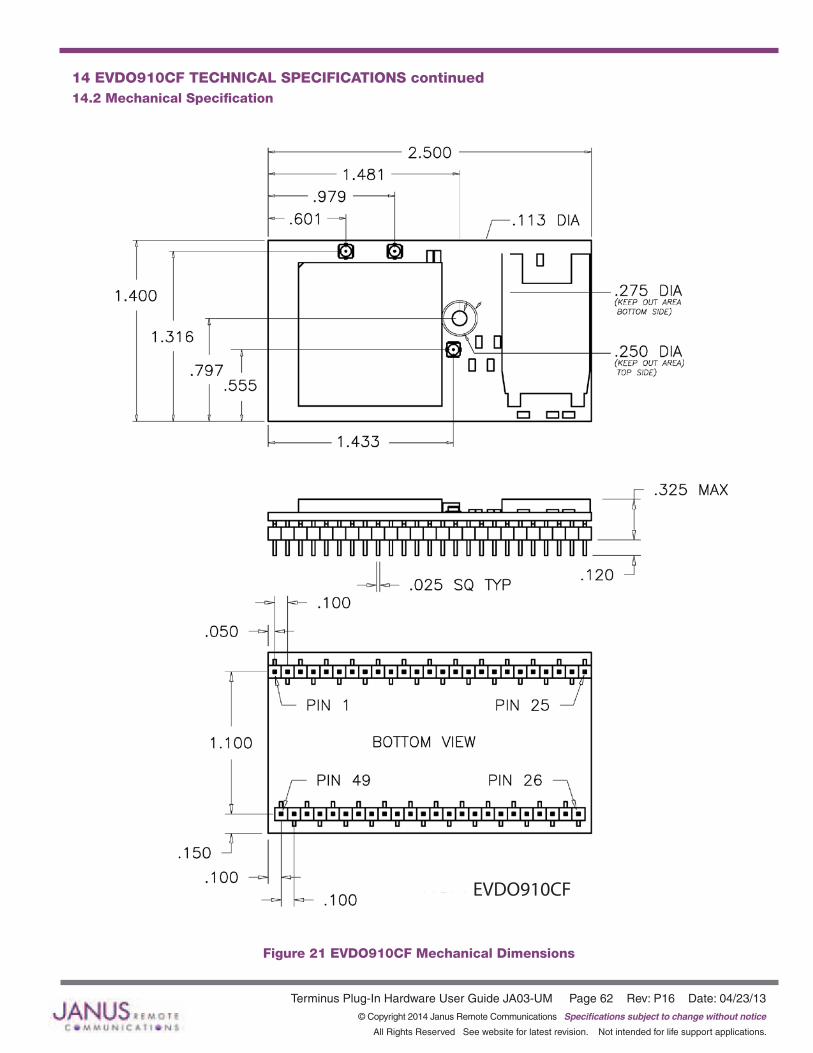
Terminus Plug-In Hardware User Guide JA03-UM Page 62 Rev: P16 Date: 04/23/13© Copyright 2014 Janus Remote Communications Specifications subject to change without notice
All Rights Reserved See website for latest revision. Not intended for life support applications.
14 EVDO910CF TECHNICAL SPECIFICATIONS continued14.2 Mechanical Specification
Figure 21 EVDO910CF Mechanical Dimensions
EVDO910CF

Terminus Plug-In Hardware User Guide JA03-UM Page 63 Rev: P16 Date: 04/23/13© Copyright 2014 Janus Remote Communications Specifications subject to change without notice
All Rights Reserved See website for latest revision. Not intended for life support applications.
14 EVDO910CF TECHNICAL SPECIFICATIONS continued14.3 Setting Up a Terminal Emulator for Use With the EVDO910CF Terminus
14.3.1 Set UpTo interface with the module, connect the serial interface to a PC and use a terminal emulation program such as Microsoft® Hyperterminal. Set the interface parameters as follows:
• Baud Rate: 115.2 kbps• Bits: 8• Stop Bits: 1• Parity: None• Hardware Handshaking: Yes
14.3.1.1 Test the Emulator Set Up• Enter AT<cr> from terminal and wait for OK
Note that Autobaud is not supported on the EVDO910CF Terminus. If you are utilizing the serial interface and you wish to change the baud rate on the module, you must use AT+IPR. You must also change the rate in the host UART (i.e. HyperTerminal) to match the new baud rate. If these do not match you will not be able to send AT commands to the module through the serial port. The Terminus is by default set to 115.2 kbps.
14.3.1.2 Verify Your Terminal and Firmware Version• Enter AT+CGMM and wait for the response
The response will be the Telit module’s model number without a command echo.• Enter AT+CGMR and wait for the response
The response will be the Telit module’s current firmware without a command echo.
Please confirm your model and firmware with the one listed in section 2.1
14.3.2 Powering ON/OFF
14.3.2.1 Turn the module ON through the following method:• Pull ON/OFF signal (Pin 19) to ground for three (3) seconds, then release.
The Terminus module is fully operational after 4 seconds. Logging onto a network may take longer than this and is outside the control of the Terminus.
14.3.2.2 There are two ways to switch OFF the module as described below.• Use the appropriate AT command (AT#SHDN)• Pull ON/OFF signal (Pin 19) to ground for three (3) seconds, then release.

Terminus Plug-In Hardware User Guide JA03-UM Page 64 Rev: P16 Date: 04/23/13© Copyright 2014 Janus Remote Communications Specifications subject to change without notice
All Rights Reserved See website for latest revision. Not intended for life support applications.
14.3 EVDO910CF GETTING STARTED continued14.3 Setting Up a Terminal Emulator for Use With the EVDO910CF Terminus continued
14.3.3 Setting Up Service
14.3.3.1 Provisioning the Plug-In Terminus To provision the unit, you will need to contact Sprint, Verizon, Aeris, or an MVNO to set up a service contract.
Please see Janus Application Note Note 111: Provisioning Guide for Terminus M2M Devices
Contact: Dave Jahr, Janus Remote Communications [email protected] 630-499-2121
14.3.4 Making a Voice Call
14.3.4.1 Set Up Voice call mode allows you to use a telephone handset to communicate with a properly equipped subscriber unit.
• Set the call mode to voice Enter AT+FCLASS=8<cr> and wait for response OK
• Dial the phone number Enter ATD <8885551234>; <cr>
• To disconnect the call enter ATH<cr>
14.3.5 Sending an SMS
14.3.5.1 Set Up SMS (Select Message Service) mode allows you to send a text message (max 160 characters) to a SMS capable subscriber unit.
• Set the SMS mode to text. This must be entered every power cycle. AT+CMGF=1<cr>
• To enter the receiving subscriber unit phone number and message enter: AT+CMGS=”8885551234” Wait for response”>” then enter message text Enter “ctrl z” <cr> to end the message
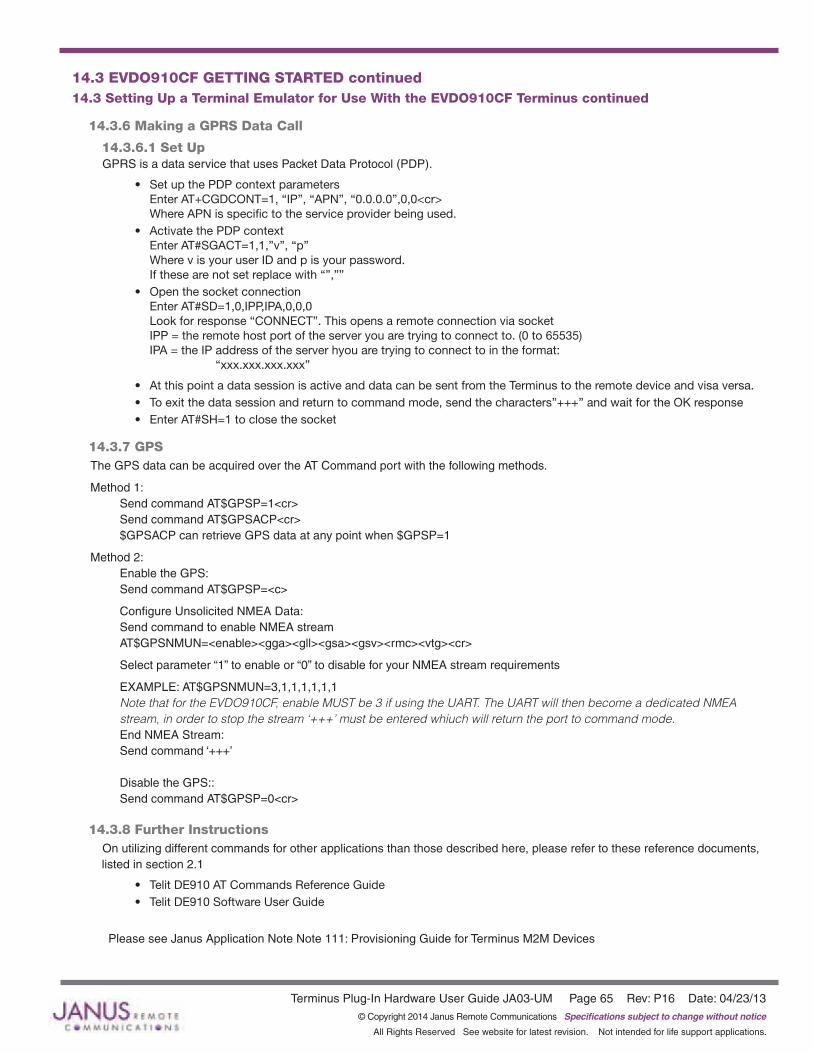
Terminus Plug-In Hardware User Guide JA03-UM Page 65 Rev: P16 Date: 04/23/13© Copyright 2014 Janus Remote Communications Specifications subject to change without notice
All Rights Reserved See website for latest revision. Not intended for life support applications.
14.3 EVDO910CF GETTING STARTED continued14.3 Setting Up a Terminal Emulator for Use With the EVDO910CF Terminus continued
14.3.6 Making a GPRS Data Call
14.3.6.1 Set Up GPRS is a data service that uses Packet Data Protocol (PDP).
• Set up the PDP context parameters Enter AT+CGDCONT=1, “IP”, “APN”, “0.0.0.0”,0,0<cr> Where APN is specific to the service provider being used.
• Activate the PDP context Enter AT#SGACT=1,1,”v”, “p” Where v is your user ID and p is your password. If these are not set replace with “”,””
• Open the socket connection Enter AT#SD=1,0,IPP,IPA,0,0,0 Look for response “CONNECT”. This opens a remote connection via socket IPP = the remote host port of the server you are trying to connect to. (0 to 65535) IPA = the IP address of the server hyou are trying to connect to in the format: “xxx.xxx.xxx.xxx”
• At this point a data session is active and data can be sent from the Terminus to the remote device and visa versa. • To exit the data session and return to command mode, send the characters”+++” and wait for the OK response • Enter AT#SH=1 to close the socket
14.3.7 GPSThe GPS data can be acquired over the AT Command port with the following methods.
Method 1: Send command AT$GPSP=1<cr> Send command AT$GPSACP<cr> $GPSACP can retrieve GPS data at any point when $GPSP=1
Method 2: Enable the GPS: Send command AT$GPSP=<c>
Configure Unsolicited NMEA Data: Send command to enable NMEA stream AT$GPSNMUN=<enable><gga><gll><gsa><gsv><rmc><vtg><cr>
Select parameter “1” to enable or “0” to disable for your NMEA stream requirements
EXAMPLE: AT$GPSNMUN=3,1,1,1,1,1,1 Note that for the EVDO910CF, enable MUST be 3 if using the UART. The UART will then become a dedicated NMEA stream, in order to stop the stream ‘+++’ must be entered whiuch will return the port to command mode. End NMEA Stream: Send command ‘+++’ Disable the GPS:: Send command AT$GPSP=0<cr>
14.3.8 Further Instructions On utilizing different commands for other applications than those described here, please refer to these reference documents, listed in section 2.1
• Telit DE910 AT Commands Reference Guide• Telit DE910 Software User Guide
Please see Janus Application Note Note 111: Provisioning Guide for Terminus M2M Devices

Terminus Plug-In Hardware User Guide JA03-UM Page 66 Rev: P16 Date: 04/23/13© Copyright 2014 Janus Remote Communications Specifications subject to change without notice
All Rights Reserved See website for latest revision. Not intended for life support applications.
GSM Pin Functions
Pin Signal Function Note 1 VBATT Main power supply 2 VBATT Main power supply 12 GND Ground 25 GND Ground 26 GND Ground 39 GND Ground 49 GND Ground 19 ON/OFF Input command for switching power ON or OFF (toggle command) 9 TXD Serial data input (TXD) from DTE 20 RESET Reset input 4 RXD Serial data output to DTE 11 RTS Input for request to send signal (RTS) from DTE 2 13 TXD_AUX 14 RXD_AUX 17 SERVICE
CDMA, UMTS, HSPA+, and EV-DO Pin Functions
Pin Signal Function Note 1 VBATT Main power supply 2 VBATT Main power supply 12 GND Ground 25 GND Ground 26 GND Ground 39 GND Ground 49 GND Ground 9 TXD Serial data input (TXD) from DTE 4 RXD Serial data output to DTE 11 RTS Input for request to send signal (RTS) from DTE 2 19 ON/OFF Input command for switching power ON or OFF(toggle command) 20 RESET Reset input
Note: 1. If the application uses USB as the main interface to the module, this is sufficient to capture any debug or trace data, provided the application can export the diagnostic port externally. 2. RTS must be connected to ground if flow control is not used. 3. USB interface required for local firmware upgrade of Telit radio.
15.2 Debug:
Debug of the GSM865CF, CDMA864CF, UMTS864CF, HSPA910CF and EVDO910CF in production
To test and debug the mounting of the module, we strongly recommend test pads on the host PCB. This will allow verification of the connection between the module itself and the application and to test the performance of the module connecting it with an external computer.
Depending on the customer application, these pads include, but are not limited to the following signals:
• TXD• RXD• ON/OFF• RESET• GND
15 DESIGN CONSIDERATIONS15.1 GSM, CDMA, UMTS & HSPA+ Minimum Required Module Pin Connects
• VBATT• TX_TRACE• RX_TRACE• PWRMON
• USB D+• USB D-• USB V_BUS• USB_ID

Terminus Plug-In Hardware User Guide JA03-UM Page 67 Rev: P16 Date: 04/23/13© Copyright 2014 Janus Remote Communications Specifications subject to change without notice
All Rights Reserved See website for latest revision. Not intended for life support applications.
APPENDICESApprovals
AT&T Certification – GSM865CF (4/11)PTCRB Certification – GSM865CF (2/11)Sprint - CDMA864CF (7/10)FCC CertifiedCE Certified
Safety Recommendations (for Information only)
Antenna Care and ReplacementDo not use the Terminus with a damaged antenna.Buy the antenna from an approved suppliers list. Using unauthorized antennas, modifications, or attachments could damage the Terminus and may violate local RF emission regulations or invalidate type approval.
Abbreviations3GPP 3rd Generation Partnership ProjectAC Alternating CurrentADC Analog To Digital ConverterBER Bit Error RateCD Carrier DetectCDMA Code Division Multiple AccessCSD Circuit Switched Data CTS Clear To SendDB DecibelDBFS Decibels Full ScaleDC Direct CurrentDCE Data Communications EquipmentDSR Data Set ReadyDTMF Dual-tone multi-frequencyDTR DTE ReadyFDN Fixed Dialing NumberGPIO General Purpose Input OutputGPRS General Packet Radio ServiceGSM Global System Mobile
ITAR International Traffic In Arm RegulationLED Light Emitting DiodeM2M Machine To MachinePBCCH Packet Broadcast Control ChannelPDU Protocol Data UnitRF Radio FrequencyRI Ring IndicatorRSSI Received Signal Strength IndicationRTS Request To SendRxD Received DataSMS Short Message ServiceTTFF Time To First FixTxD Transmitted DataUICC Universal Integrated Circuit CardUMTS Universal Mobile Telecommunications SystemUSIM Universal Subscriber Identity ModuleUSSD Unstructured Supplementary Service DataVSWR Voltage Standing Wave RatioWAAS Wide Area Augmentation System

Terminus Plug-In Products User Manual
Revision History Revision Revision Date NoteA00 12/10/09 Advanced Plug-In User ManualA01 03/31/10 Interfaces Power Supply UpdateA02 05/24/10 I/O Level Specifications Chart UpdatesP00 05/27/10 Release for publicationP01 03/17/11 Part Number Change, Getting Started Sec, Antenna InfoP02 05/02/11 GSM865CF Version Updated; V1.1P03 05/26/11 Updated Getting Started SectionsP04 08/30/11 Addition of 8.6.9 Section and new GSM865CF Block DiagramP05 09/15/11 Update to Section 10.1.3 Power SupplyP06 09/30/11 Update to Section 11.1.1 Absolute maximum RatingsP07 10/05/11 Revisions to Section 10.3 Getting StartedP08 12/09/11 Revisions to Section 8 Interfaces and 11.3.1 Set-upP09 01/17/12 General Revisions and New Section 12 - HSPA910CFP10 02/23/12 Drawings HSPA910CF 12.2 and Screw Mounting diagram; information for section 8.12; Revisions to sections 7.1/ 8.1.2 / 8.2 / 8.4/ 8.6/ 8.9P11 04/12/12 Certifications Updated for FCC and CEP12 05/17/12 HSPA910CF Power Specs RevisionsP13 08/16/12 Additional HSPA910CF Spec RevisionsP14 11/15/12 Additional EVDO910CF Spec RevisionsP15 03/18/13 Equations added to 9.5 and Section added to 9.6 - Enable PinP16 04/23/13 HSPA+ Sensitivity Updates and Provisioning UpdatesP17 03/13/14 Operating Temp Range updated for HSPA+ Section
Ordering Information
Ordering Information DescriptionGSM865CF v1.1 Terminus GSM Plug-In Module - GPS enabledGSM865CF v2.00 Terminus GSM Plug-In Module - without GPSCDMA864CF v2.00 Terminus CDMA Plug-In Module - Sprint CertifiedCDMA864CF v3.00 Terminus CDMA Plug-In Module - Verizon CertifiedUMTS864CF v1.00 Terminus UMTS Plug-In ModuleHSPA910CF v1.00 Terminus HSPA+ Plug-In Modem - GPS EnabledEVDO910CF v1.00 Terminus EV-DO Plug-In Modem
Janus Remote Communications Europe Bay 143
Shannon Industrial Estate Shannon, Co. Clare, Ireland
Phone: +353 61 475 666
Division of The Connor-Winfield Corporation2111 Comprehensive Drive • Aurora, Illinois 60505
630.499.2121 • Fax: 630.851.5040
www.janus-rc.com