tesla coil - the avalon libraryavalonlibrary.net/nikola_tesla/books/tesla coil.pdf · tesla coil...
TRANSCRIPT

Tesla coil
Spectacular fireworks include a ring of fire scribedby a wire pivoting on a phonograph needleattached to a terminal. A finer wire, attacheddirectly to a coil, produces trumpet pinwheels,shown in the smaller photo. This article tells howyou can create these fireworks
Neat housing presents a coil on a platform with allthe wiring running underneath to the transformersection behind the perforated metal cover. Notethe switches on the right side of the housing
Electricalfantasies
with a Tesla coilBy HAROLD P. STRAND
IT JUST .SITS there spitting, like a fugitivefrom a mad scientist's laboratory. The currentit's discharging—in a wicked, noisy 2-in. brush—is of such a high frequency you can't measureit, but maybe it runs up to 40,000 volts! Feelingjust a bit suicidal, you move a coin toward thisgeyser of fire. The greedy tentacles snatch towardit, but there's no shock. •
Even if you poked a finger into the brush, thecurrent would just splash over your skin.
Ever since Nikola Tesla invented a high-volt-age, high-frequency coil, science experimentershave been intrigued with their own variations onhis coil. In Tesla's time, high-frequency currentwas obtained with an induction coil as a primarysource of power. Leyden jars served as capaci-
2625
Tesla col!
tors, with a spark gap and the inductance of asecond coil combining to form an oscillatory dis-charge of high frequency. With today's vacuumtubes and mica capacitors, we can make a muchmore efficient and safer coil.
2626

Our small model operates at a resonant fre-quency of about 850 kilocycles, depending some-what on the tap selected on the lower outer coil,and the value of the capacitance used across it.
The coin stunt isn't the only fun you can havewith a Tesla coil. There are other spectaculars.Wrap the center of a length of Nichrome wirearound the terminal with the ends formed outstraight, like feelers. The ends become red-hotand bright lavender sparks quiver along the wire
A simple hand jig speeds winding of the core coilon a plastic-vase form. The crank is a threaded rodsecured through the base disk with nuts on each side,bent twice to form a handle. The crank is suspendedbetween two brackets
as each half begins to rotate. Two fiery trumpetsblaze forth in the darkened room. Just why thewire ends rotate is not known.
Another bit of fireworks results when youbalance a wire rotor (detailed in the color panelon page 2629) on the point of a phonographneedle erected on the terminal. Jet propulsionfrom the corona discharges at each end sets therotor spinning. The result is a startling ring of fire.
No less intriguing are three other demonstra-
After you finish the assembly, read the platecurrent by connecting a D.C. milliammeter betweenthe center tap of the filament transformer andground. Adjust the rheostat to 150 ma. maximumfor any combination of capacitors and taps
2627

TesSa coll
Sample experiments include (top) lighting afluorescent tube by simply moving it into thehigh-frequency current field surrounding thecoil; (center) lighting a 115-volt light bulbwithout plugging it into a power line—bymeans of energy radiated to a sheet-metalplate; (bottom) passing the current from thecoil's own brush discharge through a metalrod taped on a plastic strip to form a duplicatebrush at the other end
tions. Holding a fluorescent tube near the coilactivates the phosphors on the inside, causing amysterious glow. Various types of neon lampswill also light when introduced into the coil'sfield. Since this field is strongest near the coil, asyou draw the lamp away it dims, then goes out.
illustrating Tesla's dreamOne experiment graphically illustrates Tesla's
dream of lighting entire buildings from a distancewithout wires. As shown, you erect a sheet ofaluminum on an insulating stand, to serve as acollector for currents radiating from the coil. At-tach one clip lead to the plate and to one side ofa small 115-volt lamp; another clip lead connectsthe other side of the lamp to ground. When thecoil is switched on, the plate picks up energy andlights the lamp. The closer the plate is movedto the coil, the brighter the lamp glows. If youdisconnect the lamp, you can draw sparks fromthe plate to your fingers, indicating that the plateis charged by radiation from the coil.
Another experiment (not shown) demon-strates that this peculiar form of current seems topass through material that's considered a goodinsulator. A piece of 1/4-in. plastic, held in a sparkgap connected from the top terminal and theground post, seems to offer no resistance—youcan watch the discharge continue to jump thegap. You can also conduct this experiment withother insulation materials of various thicknesses.
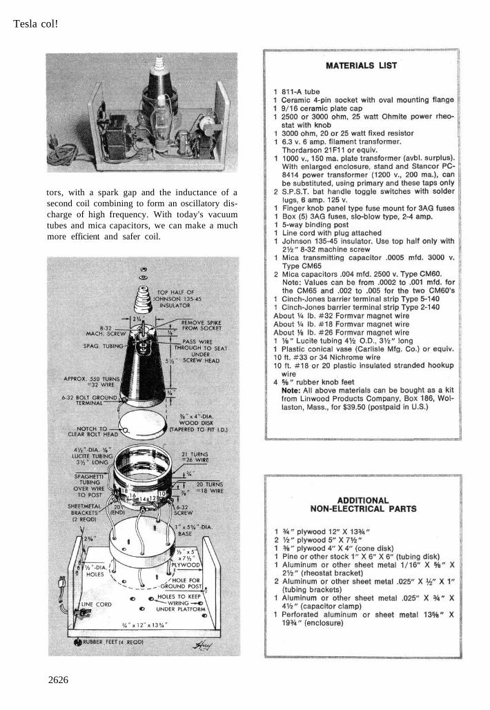
Start construction with the tall, tapered; corecoil. The winding form is a plastic flower vasewith a stake base. Be sure it's plastic. Removethe spike by pulling it out of its socket and drill acenter hole through the socket bottom for a ma-chine screw long enough to pass through the topinsulator. At the large end make up a plywooddisk with tapering edges, to exactly fit the open-ing. Drill 3 equally spaced holes through theedge of the vase for small nails, driven into theplywood edge. Fastening is temporary; the diskmust be removed for interior connections.
Bore a center hole in the disk to pass whateverspindle you've devised for the winding process.This type of jig is pictured in operation. A sim-pler setup would be to pass plain rod through theform, cradling each end on a notched upright.Bend the spindle's projecting end to form a crank.
Apply a thin, even coat of varnish to the vaseand let it dry enough to get tacky. Coil up about2 in. of wire and tape it out of the way at theupper end of the vase-form. Wind the turns onin a single even layer with no overlap or spacebetween. The tacky varnish prevents the turns
2628

from slipping out of place on the smooth plastic.When you're within 5/8-in. of the edge, anchor
the end of the wire with tape. The height of thewinding should be about 5-1/2-in.; that's roughly550 turns—but it's not critical enough to warrantan actual count. At the top of the coil, bore asmall hole just beyond the point where the turnsend, to pass a piece of small-diameter spaghettitubing. Slip this over the hole to the inside. Cleanthe end of the wire by holding it over a match amoment, then burnish with sandpaper beforeclamping it under the head of the insulator screw.Coat the head with quick-dry varnish or shellacto eliminate possible corona discharges here. Ap-ply two or more even coats of varnish to thewinding, letting each dry thoroughly.
The two outer coils are wound on the Lucitetubing without any sort of jig. The start of thelower coil has a permanent terminal; a secondterminal provides a short lead that can connectto any of the taps. Two terminals are also pro-vided for the ends of the upper coil, at the op-posite side of the tube. For connections to theseterminals, slip on pieces of spaghetti tubing wherethe wires cross the lower coil, and make sure theleads don't contact it, as shorting might result.
This disk is cut to 5-3/4 in. dia. as shown in theexploded view, then positioned temporarily onthe platform so you can drill holes (to pass the5 leads) through both thicknesses at once. Cen-ter the core coil on the base disk and drive twoflathead screws up through it, countersinkingthem flush. Now drop the outer coil unit downover the core coil (after cutting a notch in thetubing to clear the inner terminal).
In the photo, page 2626, the 1000-v. trans-former is at the left and the filament transformer
is at the right. The tube socket has been mountedwith spacers so it will clear the bottom connec-tions. The rheostat for the grid control is brack-eted to the side. Use plastic insulated strandedwire with clamp-on terminal lugs at all screwterminals.
The milliammeter you use to adjust the platecurrent (bottom right photo, page 2627) shouldhave a scale of 0-300 or more. To hook it intothe circuit, remove the center tap of the filamenttransformer from the ground and connect it toone side of the meter with a clip lead; anotherlead connects the other side of the meter to theground terminal. If, when you turn on the power,the meter reads down scale, reverse the leads. Toavoid shock, be sure all power is off before youtouch any wires or connections around the coil.
The strong brush discharge shown in severalphotos indicates a good combination of capacitorvalue and the best tap on the low outer coil. Youcan experiment with various capacitor values andtaps while adjusting the grid resistance to keep itwithin the 150-ma. limit for the plate current.When the best combination has been found,solder the lead to the tap selected. You'll, have toscrape the varnish off each tap with a sharp knifeand sandpaper before making any connection.
When operating the coil, be sure to turn onthe filament switch first and let the tube warmup 15-20 seconds before you flip the plate switch.
Note that a ground post has been provided atthe opposite side from the switches. You canground the coil with a clip lead to a water pipe orradiator. This post may also be required in someexperiments requiring both the ground and high-voltage sides of the circuit.
2629