test equipment depot - 800.517.8431 - 5 commonwealth ave
TRANSCRIPT

Data Sheet
RF Power Meter RFM3000 Series
The RFM3000 Serles of meters work In combination with B&K Precision's RFP3000 Serles of USB RF Peak
Power Sensors to extend their capabllllles and eliminate the need for a remote computer. This benchtop
solution supports capturing. dlspl<!}'lng. and ana[yzlng peak and average RF power In both the time and
statistical domains through an Intuitive. multi-touch touchscreen dlspl<!}'.
Two on-screen markers can be dragged over a waveform for greater measurement details. A selection of
useful trigger options and channel synchronization settings provide the perfect tool set for working with
multiple channel measurements.
Measurement modes
Measurement modes can be QUlck!Y changed form Continuous to Pulse or Statlsllcal modes with one touch.
-Continuous mode
For simple. Intuitive measurements of repetitive
waveforms. the RFM3000 Serles Continuous
Mode of operation provides a numeric display of
average. maximum and minimum signal powers.
Technical data subject to change © B&K Precision Corp. 2021
-Pulsed mode
Ana!Ysls of fast-rising single pulses or pulses with
short pulse repetition Intervals (PRls) reQulres
an Instrument with sophisticated trigger and data
acQulsltlon capablli\)'. Within Pulsed Mode. more
than 16 pulse parameters can be measured.
BK PRECIS.-�I
□ LAN
Features and benefits
■ Compatible with RFP3000 Serles USB RF
Peak Power Sensors
■ Capture/dlsplay/ana!Yze peak and average
power
■ Independent or synchronous multi-channel measurements (up to 4 channels)
■ Trigger synchronization
■ Test source for sensor verification
■ Display 16 common power measurements
■ Ethernet:10/100/1000 Basel; HISLIP
■ Supports SCPl-1999.0
■ HDMI output for mirror display
■ Sensors can be used as standalone Instruments
1,i. Statistical mode
Complementary Cumulative Distribution Function
or CCDF plot shows the rate of occurrence of
a specific crest factor for signals. such as those
used In SG. 4G/LTE. and WI-Fl applications.
Test Equipment Depot - 800.517.8431 - 5 Commonwealth Ave, Woburn MA 01801 - TestEquipmentDepot.com
RF Power Meter
RFM3000 Series
Addressing RF communications and radar measurement challenges
Wi-Fi and wireless communication signal analysis
Characterization and compliance testing of WI-Fl and LTE chlpsets and devices Involves significant challenges for design and test
engineers. With multiple-Input, multiple-output (MIMO) architectures and channel bandwidths up to 160 MHz.testing Is complex, especial!}' when measuring RF power per channel and time alignment between channels. The RFM3000 Serles enables packet power
measurements to be performed Independent!}' on multiple synchronous or asynchronous transmit chains with a common timebase shared
among sensors.
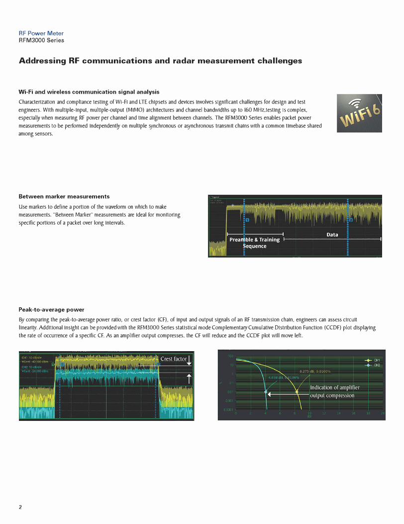
Between marker measurements
Use markers to define a portion of the waveform on which to make
measurements. '"Between Marker'" measurements are Ideal for monitoring
specific portions of a packet over long Intervals.
Peak-to-average power
By comparing the peak-to-average power ratio, or crest factor (CF), of Input and output signals of an RF transmission chain, engineers can assess circuit
linearl\}'. Additional Insight can be provided with the RFM3000 Serles stallstlcal mode Complementary Cumulative Distribution Function (CCDF) plot displaying
the rate of occurrence of a specific CF. As an amplifier output compresses, the CF will reduce and the CCDF plot will move left.
2

RF Power Meter RFM3OOO Series
Addressing radar measurement challenges
Secondary Surveillance Radar (SSR)
Design. verification, troubleshooting and maintenance of secondary surveillance radar (e.g. I FF-based radar) has
never been more demanding.
Secondary Surveillance Radar (SSR)
Proper design and operation of SSR systems Is critical to the safeo/ and
securlo/ of aviation. The RFM3OOO Serles can be used to easl[y and
accurate!}' capture SSR waveforms. Markers enable measurements on
specific portions of the waveform.
Rise time and resolution
Industry-leading rise time ( < 3 ns) enables characterization of the most
demanding radar signals.
Utilize the superior JOO ps time resolution to zoom and uncover signal
characteristics that might otherwise be missed.
Pulse measurements
Users can take advantage of the RFM3OOO Serles automated pulse
measurement feature to measure and calculate 16 common power and
timing parameters and display the parameters of Interest: rise-time. fall
time, pulse width, off-time, period, pulse repetition freQ.uency. duo/ cycle,
pulse peak, pulse overshoot, pulse average. waveform average. top level
power, droop. bottom level power, edge delay. and pulse edge skew
between channels.
3
Param
Width
Rise
Full
Period
PRF
Duty
Offtimc
WavAv
PulsAv
Puls Pk
OvrSht
CHl
30 080 µs
21 061 µs
22 395 µs
999. 77 µs
1 0002 kHz
3 01
969.69 µs
14.158dBm
0.484 dBm
1.327 dBm
0.290 dB
11
) lh
21 132 µs
23 404 µs
)')1_1 ()·j fJ.i
I UJC, I kH;
�J1 ... ,1:1 :3'3 µ�
5.c<-'.:3 dE:rn
·:•.4<-'.c dE:m
1 ,:,_,:,r,,g dE:rn
r, 11 -, ilR
RF Power Meter
RFM3000 Series
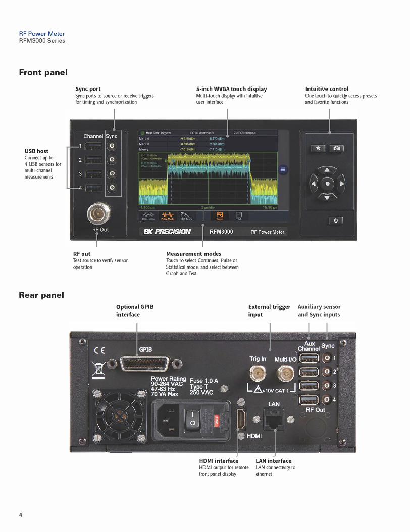
Front panel
USB host Connect up to
4 USB sensors for multi-channel measuremenls
Rear panel
4
Sync port Sync ports to source or receive triggers for timing and synchronlzallon
RF out Test source to verify sensor operallon
Optional GPIB
interface
5-inch WVGA touch displayMulti-touch dlspl<!)' with lnlultlve user lnlerface
Measurement modes Touch lo select Continues, Pulse or Statlsllcal mode, and select between Graph and Texl
External trigger
input
HDMI interface HDMI outpul for remole
fronl panel display
LAN interface LAN connectlvl\}' lo
ethemet
Intuitive control One touch lo Quick� access presets and favorite functions
Auxiliary sensor
and Sync inputs

RF Power MeterRFM3000 Series
5
Specifications
RFM3000 Series
Channels 2 or 4 channels
Display
Display Size 5-inch WVGA multi-touch display with intuitive graphical user interface
Display ModesGraph (power vs time) - Numeric (numeric data) - Statistical measurements - CCDF
Automatic measurements (pulse, statistical, and marker measurements)
Marker Measurements (in Graph view)
Markers (vertical cursors) Settable in time relative to the trigger position
Marker Independently Avg, Min and Max Power at a specified time offset
Interval Between Markers Avg, Min and Max Power over the defined interval
Pair of Markers Ratio of power values at each marker
Pulse Mode
Automatic MeasurementsPulse rise-time - Pulse fall-time - Pulse width - Pulse off-time - Pulse period - Pulse repetition frequency
Pulse duty cycle - Waveform average - Pulse peak - Pulse average - Pulse overshoot - Pulse droopTop level power - Bottom level power - Edge delay - Pulse edge skew between channels
Statistical Mode
Automatic MeasurementsPeak power - Average power - Minimum power - Peak to average ratio - Dynamic range
Percent at cursor - Crest factor at cursor - Crest factor at various percents
Trigger
Synchronization Internal trig distribution
Mode Normal, Auto, Auto Pk-to-Pk, Free Run
Source Any connected RTP Series sensor (via SMB’s) or rear panel external trigger
Internal Level Range -40 dBm to +20 dBm (sensor dependent)
External Level Range ± 5 volts or TTL
Slope + or -
Hold-off, Min Pulse Width, Max Trigger Rate
Sensor and timebase dependent
Time Base
Time Base Resolution, Range, Accuracy
Sensor dependent
Time Base Display Sweeping or roll mode
Trigger Delay Range Sensor dependent
Trigger Delay Resolution 0.02 divisions

RF Power MeterRFM3000 Series
6
Specifications (cont.)
RFM3000 SeriesInputs/Outputs (front panel)
USB with SMB trigger port 4 ports USB2.0: Type A receptacle, 4 ports SMB(f)
Test Source(optional rear panel placement)
50 MHz 1.00 mW (0 dBm) ± 2.3% (0.1 dB) typical
Inputs/Outputs (rear panel)
LAN 10/100 Ethernet: RJ-45 modular socket
USB with SMB trigger port 4 ports USB2.0: Type A receptacle, 4 ports SMB(f)
Multi I/O Connector
User Selectable Status, trigger, or voltage output
Range
0 to 10 V (Analog unipolar)
-10 V to +10 V (Analog bipolar)
0 or 5 V (Logic)
Accuracy ±200 mV (±100 mV typical)
Linearity 0.4% typical
Remote Control
Command Set SCPI-1999.0
LAN Ethernet: 10/100/1000 BaseT; HiSLIP
GPIB Optional
Regulatory Compliance
CE compliance with the following European Union directives
Low Voltage Directive: 2014/35/EU, RoHS Directive: 2011/65/EU, WEEE Directive 2012/19/EU,
Electromagnetic Compatibility Directive (EMC): 2014/30/EU and Environmental: MIL-PRF-28800F, Class 3
General
Power Requirements 90 to 260 VAC, 47 to 60 Hz; 90 to 135 VAC, 47 to 400 Hz; 30 W (35 VA) max
Operating Temperature 0 to 50 °C (32 to 122 °F)
Storage Temperature -40 to +70 °C (-40 to 158 °F)
Humidity 95% maximum, non-condensing
Altitude Operation up to 15,000 feet (4600 m)
Shock Withstands ± 30 G, 11 ms impulse in X, Y, and Z axes
Vibration Withstands 2 G sine, 5 to 55 Hz; 2 G random, 5 to 500 Hz
Warranty 3 Years
Dimensions (excluding connectors) (H x W x D) 3.5" x 8.3" x 11.2" (89 x 211 x 284 mm)
Weight 4.8 lbs (2.2 kg)
Included Accessories Power cord
Optional AccessoriesRKRFM Full-width 19” Rack Mount Kit (includes handles & hardware for mounting one
or two meters)
Note: All specifications apply to the unit after a temperature stabilization time of 15 minutes over an ambient temperature range of 23 °C ± 5 °C. Specifications are valid for single unit operation only.

RF Power Meter RFM3000 Series
Specifications
Ordering Information
RFM3000 Series
RFM3002 RFM3004
RFM3002-GPIB
RFM3004-GPIB
RF Power Meter with 2 active channels RF Power Meter with 4 active channels
RF Power Meter with 2 active channels and GPIB
RF Power Meter with 4 active channels and GPIB
High-performance USB power sensors
The RFM3000 Serles Power Meter utlllzes RFP power sensors with Industry leadlng performance and capabllltles. All RFP sensors Incorporate Real-Time
Power Processing technology. which vlrtual[y ellmlnates gaps In measurement suffered by other power sensors and enables Industry leading measurement
speeds. In terms of RF performance. the RFP3000 Serles Real-Time Peak Power Sensors are the fastest responding sensors with 3 ns rise times and 195 MHz
of video bandwidth.
7
RFP3000 Series real-time peak power sensors
SO MHz to 6 GHz. 18 GHz and 40 GHz peak power RF sensors
Up to 195 MHz video bandwidth with 3 ns rise time
Crest factor and stallstlcal measurements (e.g .. CCDF)
10 GS/s effective sample rate
Real-Time Power Processing technology with vlrtual[y
zero measurement latency
100,000 measurements per second
80 dB dynamic range
Synchronized multi-channel measurements
v060821
For more Information on the RF sensors see the RFP3000 Serles data sheet
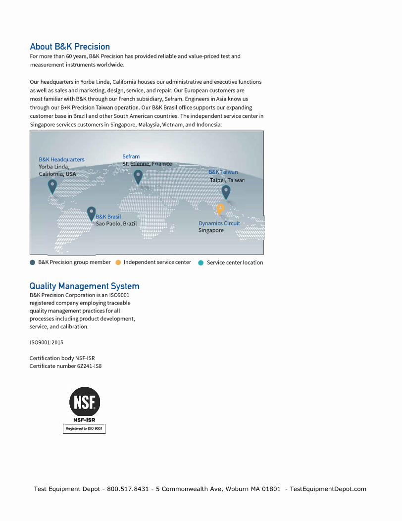
About B&K Precision For more than 60 years, B&K Precision has provided reliable and value-priced test and
measurement instruments worldwide.
Our headquarters in Yorba Linda, California houses our administrative and executive functions
as well as sales and marketing, design, service, and repair. Our European customers are
most familiar with B&K through our French subsidiary, Sefram. Engineers in Asia know us
through our B+K Precision Taiwan operation. Our B&K Brasil office supports our expanding
customer base in Brazil and other South American countries. The independent service center in
Singapore services customers in Singapore, Malaysia, Vietnam, and Indonesia.
Sefram B&K Headquarters Yorba Linda, California, USA
St. Etienne, F:nraiiinii'ce�--..----
B&KBrasil Sao Paolo, Brazil
B&KTaiwan
Dynamics Circuit Singapore
e B&K Precision group member e Independent service center e Service center location
Quality Management System B&K Precision Corporation is an ISO9001
registered company employing traceable
quality management practices for all
processes including product development,
service, and calibration.
ISO9001:2015
Certification body NSF-ISR
Certificate number 6Z241-IS8
NSF•ISR
I Regi•ten>d to ISO 9001 I
Test Equipment Depot - 800.517.8431 - 5 Commonwealth Ave, Woburn MA 01801 - TestEquipmentDepot.com