test equipment plus headless signal hound api for … · - i - test equipment plus headless signal...
TRANSCRIPT
TEST EQUIPMENT PLUS
"Headless Signal Hound" API for the USB-SA44B version 0.2
Headless Signal Hound
Programming Interface

- i -
T E S T E Q U I P M E N T P L U S
Headless Signal Hound USB-SA44B
Application Programming Interface (API)
2012, Test Equipment Plus 35707 NE 86th Ave
Phone (360) 263-5006 • Fax (360) 263-5007
This information is being released into the public domain in accordance with the Export Administration Regulations 15 CFR 734

- i -
Table of Contents
Introduction _____________________________________________________________________________________________________________ 1
Setup and Initialization ____________________________________________________________________________________________________ 2
Setup ________________________________________________________________________________________________________________ 2
Signal Hound Initialization ______________________________________________________________________________________________ 2
Sweeping _______________________________________________________________________________________________________________ 4
Normal (Amplitude vs Frequency) Sweeps _________________________________________________________________________________ 4 Interpreting the Sweep Results ___________________________________________________________________________________________ 4
RBW / VBW, Limitations and Automatic Setting ____________________________________________________________________________ 5
Video Processing, Manual RBW / VBW ____________________________________________________________________________________ 5
Sensitivity and IF Gain Settings __________________________________________________________________________________________ 6
Preamplifier and Attenuator Settings ______________________________________________________________________________________ 6
Zero Span Sweeps _____________________________________________________________________________________________________ 7
Harmonics Utility ______________________________________________________________________________________________________ 8
Audio Demodulation ___________________________________________________________________________________________________ 8
Sample Applications ____________________________________________________________________________________________________ 8
Utilities ________________________________________________________________________________________________________________ 9
Channel Power and Adjacent Channel Power _______________________________________________________________________________ 9
Phase Noise Sweeps ___________________________________________________________________________________________________ 10
Function Listing ________________________________________________________________________________________________________ 11
Class CMySignalHound ________________________________________________________________________________________________ 11 Important variables in the CMySignalHound class ________________________________________________________________________ 17
CSettings class (CMySignalHound.m_settings) _____________________________________________________________________________ 18 Important variables in the CSettings Class _________________________________________________________________________________ 18
MEAS_RCVR_STRUCT _______________________________________________________________________________________________ 20
CAudioStream Class __________________________________________________________________________________________________ 21 Important variables in the CAudioStream Class _____________________________________________________________________________ 21
Miscellaneous Functions (no class) _______________________________________________________________________________________ 21
ERROR CODES______________________________________________________________________________________________________ 22
- 1 -
Introduction
About the Headless Signal Hound API and building applications.
he Headless Signal Hound Application Programming Interface is a tool for software engineers to design custom applications for the Signal Hound, built on the actual core engine that drives the Signal Hound software application.
DISCLAIMER—This API is provided free of charge, without warranty. Software developers may only use this API with a genuine Signal Hound™.
A software application will create a "CMySignalHound" object, which will act as the software representation of the connected "Signal Hound" device.
CMySignalHound myHound;
The software application must initialize this object before its use. This may take a few seconds, and binds the object to a particular Signal Hound, so it is not done in the class constructor. Initialize returns an error code if it fails.
int errorCode = myHound.Initialize();
To succeed, the application must be able to find 2 files in the current file path: "<serial number>.tep", and "D<serial number>.bin"
The Signal Hound is now ready to begin sweeping. The settings, found in myHound.m_settings, control how the Signal Hound sets up for and runs each sweep. These settings may be controlled directly, or changed through the use of one of the functions found in MySignalHound.h.
A sample application is available to you, which illustrates the use of these classes.
The API consists of libSHAPPLIB.a, which must be statically linked to at compile-time. Additionally, two headers expose the functions and settings for the user-accessible classes.
Chapter
1
T

2
Setup and Initialization
Setup
Prior to launching your Headless Signal Hound API application, you will need to have everything set up. This includes making sure the FTDI driver is loaded, the cal data is in your application's "path", and your application is compiled using the Headless Signal Hound API.
The "cal data" consists of two files: "<your serial number>.tep" and "D<your serial number>.bin". Both of these files should be loaded into the application's folder or path before launching the application. For calibrated frequency and amplitude readings, these files must be present and match the serial number used..
To install the FTDI drivers for a Linux environment, follow the instructions found here: http://www.ftdichip.com/Drivers/D2XX/Linux/README.dat
The Signal Hound uses the D2XX drivers. For Linux, this means that if your build already includes the Virtual COM port, or VCP, drivers (Ubuntu does by default), you must "rmmod" or "blacklist" ftdi_sio and usbserial.
Your application will not launch until the FTD2XX drivers are installed correctly.
Signal Hound Initialization
After you launch your application, the first thing to do is to create a "CMySignalHound" object, which will act as the software representation of the connected "Signal Hound" device.
CMySignalHound myHound;
The constructor will set variables and pointers to their default values, but will NOT connect to the Signal Hound. To actually connect to the Signal Hound, call:
int errorCode = myHound.Initialize();
The Initialize function will return 0 for success, or an error code as follows:
Chapter
2
3
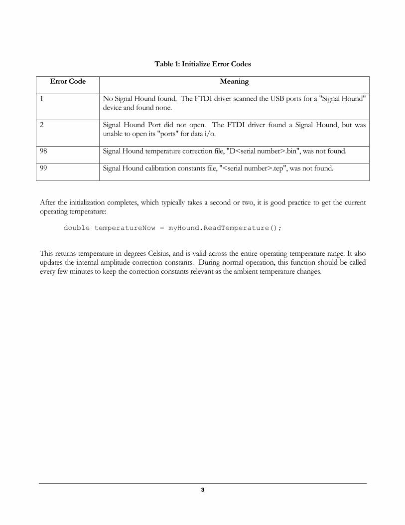
Table 1: Initialize Error Codes
Error Code Meaning
1 No Signal Hound found. The FTDI driver scanned the USB ports for a "Signal Hound" device and found none.
2 Signal Hound Port did not open. The FTDI driver found a Signal Hound, but was unable to open its "ports" for data i/o.
98 Signal Hound temperature correction file, "D<serial number>.bin", was not found.
99 Signal Hound calibration constants file, "<serial number>.tep", was not found.
After the initialization completes, which typically takes a second or two, it is good practice to get the current operating temperature:
double temperatureNow = myHound.ReadTemperature();
This returns temperature in degrees Celsius, and is valid across the entire operating temperature range. It also updates the internal amplitude correction constants. During normal operation, this function should be called every few minutes to keep the correction constants relevant as the ambient temperature changes.

4
Sweeping
Normal (Amplitude vs Frequency) Sweeps
When RBW and VBW are set to auto, sweeping is straightforward. Simply set your start and stop frequency (or center frequency and span), set up the sweep, and call DoSweep(): myHound.SetCenterAndSpan(centerfreq, span);
myHound.SetupForSweep();
myHound.DoSweep();
You may repeatedly call DoSweep() to update the trace. Whenever settings are changed, you must call SetupForSweep() before you do the sweep.
Interpreting the Sweep Results
The sweep is stored into arrays of double precision floating point min / max data, myHound.pDataMax and myHound.pDataMin (in milliwatts). The sweep's center frequency corresponds to index (myHound.m_traceSize / 2). All other points are separated by (myHound.m_HzPerPt). The sweep's resolution bandwidth, trace size, and Hz per point can be found by:
double myRBW = GetRBWFromIndex(myHound.m_settings.m_RBWSetpoint);
int myTraceSize = myHound.m_traceSize;
int myHzPerPoint = myHound.m_HzPerPt;
Finding the peak amplitude and frequency would be found by:
int peakidx=0;
for(i=1; i<myHound.m_traceSize; i++)
if(myHound.pDataMax[i] > myHound.pDataMax[peakidx]) peakidx=i;
double peakFreq = myHound.GetFrequencyFromIdx(peakidx);
double peakAmpl = mW2dBm(myHound.pDataMax[peakidx]); // in dBm
Chapter
3
5
RBW / VBW, Limitations and Automatic Setting
The Headless Signal Hound API generally limits the RBW and VBW for sweeps, such that the maximum RBW allowed is 1/10 of the span, and the minimum RBW allowed is 1/5000 span. This will keep the trace size between approximately 36 and 18000. A trace smaller than 36 will look funny when displayed, and a trace larger than 18000 points can take a long time to process and display. There are other restrictions on RBW and VBW as well. As the software transitions from "slow sweeps" with spans of 500 KHz or less, to "fast sweeps" of 5 MHz or more, the minimum RBW becomes 6.5 KHz. For spans between 500 KHz and 5 MHz, the user can set RBW and "Sweep Time Setpoint" to control whether slow sweep or fast sweep is used. Slow sweeps of 1 MHz or more can take several seconds to complete. The default settings put the transition between a span of 500 KHz and 1 MHz.
Generally, users will wish to use the automatic RBW / VBW settings. These were established to give a trace size of roughly 1000 in most cases, which displays nicely on a typical computer screen and processes fairly quickly.
Video Processing, Manual RBW / VBW
For low level data, or to see an average envelope, video processing is often desirable. To enable video processing, VBW must be set to less than RBW, and video mode must not be set to bypass. For example, to set up for 100 Hz RBW, 25 Hz VBW, log scale processing (most common on spectrum analyzers), using an "average" power detector, do the following:
//Turn on video processing, set RBW to 100 Hz, VBW to 25 Hz
myHound.m_settings.m_VBWSetpoint = myHound.m_settings.GetBWIDX(25.0);
myHound.m_settings.m_RBWSetpoint = myHound.m_settings.GetBWIDX(100.0);
myHound.m_settings.m_VDMode = HOUND_PROCESS_AS_LOG;
myHound.m_settings.m_VDMMA = HOUND_VDMMA_AVERAGE_ONLY;
myHound.m_settings.m_RBWIsAuto = false;
myHound.m_settings.m_VBWIsAuto = false;
myHound.SetupForSweep();
For applications where a large "capture time" is desired, such as when you need a high probability of capturing a rare event (image rejection off), the m_settings.m_SWPTMSetpoint controls the sweep speed, in a loose sense, from fast (0) to very slow (3 or 4). The default setting is 0. A setting of -1 forces sweeps to be as fast as possible, but generally should not be used.
The RBW and VBW will be limited in software to between 1/10 the span and 1/5000 the span, so if you attempt to set the RBW or VBW to an unacceptable value, the function SetupForSweep will return a nonzero value.
6
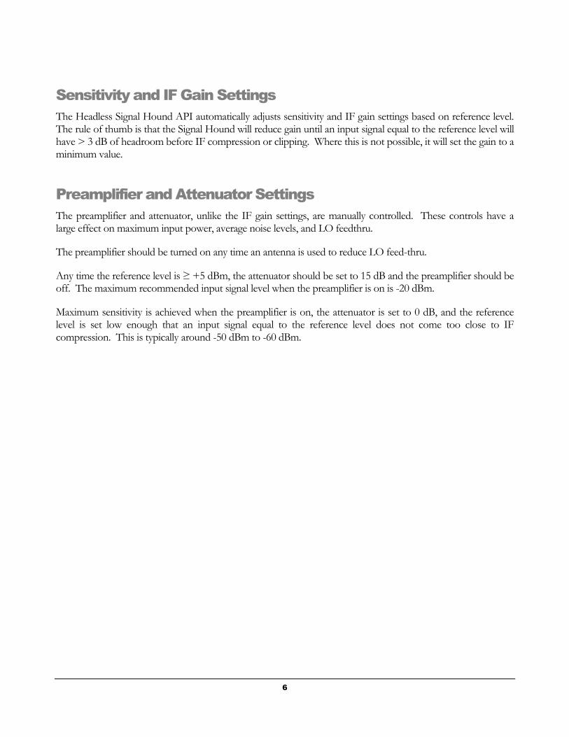
Sensitivity and IF Gain Settings
The Headless Signal Hound API automatically adjusts sensitivity and IF gain settings based on reference level. The rule of thumb is that the Signal Hound will reduce gain until an input signal equal to the reference level will have > 3 dB of headroom before IF compression or clipping. Where this is not possible, it will set the gain to a minimum value.
Preamplifier and Attenuator Settings
The preamplifier and attenuator, unlike the IF gain settings, are manually controlled. These controls have a large effect on maximum input power, average noise levels, and LO feedthru.
The preamplifier should be turned on any time an antenna is used to reduce LO feed-thru.
Any time the reference level is ≥ +5 dBm, the attenuator should be set to 15 dB and the preamplifier should be off. The maximum recommended input signal level when the preamplifier is on is -20 dBm.
Maximum sensitivity is achieved when the preamplifier is on, the attenuator is set to 0 dB, and the reference level is set low enough that an input signal equal to the reference level does not come too close to IF compression. This is typically around -50 dBm to -60 dBm.

7
Zero Span Sweeps
Zero span sweeps require some additional settings. When you exit "zero span" you must restore the RBW / Sweep settings // This illustrates Zero Span Frequency Demodulation settings.
myHound.m_settings.m_sweepMode = HOUND_SWEEP_MODE_ZERO_SPAN;
myHound.m_settings.m_ZSMode = HOUND_ZS_MODE_FREQUENCY;
//This selects frequency modulation (FM),
// not amplitude modulation (AM)
myHound.m_settings.m_RBWSetpoint = HOUND_IFBW_60kHz;
//60 KHz IF bandwidth
myHound.m_settings.m_VBWSetpoint = HOUND_IFBW_60kHz;
myHound.m_settings.m_ZSSweepTime = 0.005;
//5 milliseconds. Should be good for any audio freq >200 Hz
myHound.SetCenterAndSpan(peakFreq,0.0);
myHound.SetupForSweep();
myHound.DoSweep();
You may select virtually any sweep time. IF bandwidths are limited to the values in the HOUND_IFBW table. Points are separated in time by (sweep time / (myHound.m_traceSize - 1) ). Amplitude demodulation yields amplitude values (mW), frequency demodulation yields frequency values (Hz).

8
Harmonics Utility
This is probably easiest to implement manually. Simply call myHound.SetCenterFrequencyAndSpan() for each harmonic you wish to check, and report the peak signal level.
Audio Demodulation
Streaming audio from the Signal Hound is accomplished through the CAudioStream class. In essence, CAudioStream uses the current attenuator and sensitivity settings, sets up for continuous data acquisition, and makes packets of demodulated audio data available to your application. A sample application (built in Windows in this case) might:
short * pBigData = new short[20480];
CAudioStream * pStream = (CAudioStream *) pHound->OpenAudio();
for(i=0; i<5; i++) //5 packets
pStream->ReadAudioChunk(&pBigData[i*4096]);
for(i=0; i<5; i++) //Pre-load 5 packets into buffer to avoid "popping"
writeAudio(hWaveOut, (char *)(&pBigData[i*4096]), 8192); // OS-specific
while(streaming)
{
pStream->ReadAudioChunk(&pBigData[0]);
writeAudio(hWaveOut, (char *)(&pBigData[0]), 8192); // OS-specific
}
pHound->CloseAudio(pStream);
To use in Linux, you will need to connect to the sound card using a Linux library.
Sample Applications
The first project, PRE1, is a pre-release with much of the functionality and class structure in place. It illustrates sweeping, automatic and manual bandwidth control, span, center frequency, zero span, and video processing. It was built using CODE::BLOCKS 10.05

9
Utilities
Channel Power and Adjacent Channel Power
Channel Power is available after any sweep with an RBW of ≤ 100 kHz. Internally, channel power integrates across multiple "bins" from the FFT, then divides by the equivalent bandwidth of the FFT window function.
Your channel bandwidth should be at least twice your RBW, and typically more like 10 times as large. To use:
1. Set your channel bandwidth and spacing, in Hz:
myHound.m_channelBW = 10.0e3; //Hz
myHound.m_channelSpacing = 10.0e3; //Hz
2. Get your channel power, in dBm:
double channelPower = myHound.GetCP();
3. Get your adjacent channel powers (ACP), in dBm, and compute ACPR, in dBc:
double lowerACPR = myHound.GetACPL() - channelPower;
double higherACPR = myHound.GetACPR() - channelPower;
Chapter
4
10
Phase Noise Sweeps
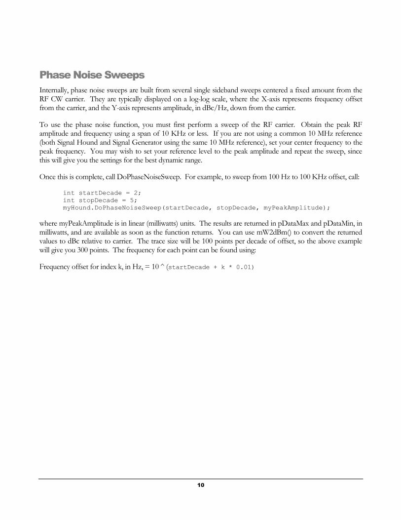
Internally, phase noise sweeps are built from several single sideband sweeps centered a fixed amount from the RF CW carrier. They are typically displayed on a log-log scale, where the X-axis represents frequency offset from the carrier, and the Y-axis represents amplitude, in dBc/Hz, down from the carrier.
To use the phase noise function, you must first perform a sweep of the RF carrier. Obtain the peak RF amplitude and frequency using a span of 10 KHz or less. If you are not using a common 10 MHz reference (both Signal Hound and Signal Generator using the same 10 MHz reference), set your center frequency to the peak frequency. You may wish to set your reference level to the peak amplitude and repeat the sweep, since this will give you the settings for the best dynamic range.
Once this is complete, call DoPhaseNoiseSweep. For example, to sweep from 100 Hz to 100 KHz offset, call:
int startDecade = 2;
int stopDecade = 5;
myHound.DoPhaseNoiseSweep(startDecade, stopDecade, myPeakAmplitude);
where myPeakAmplitude is in linear (milliwatts) units. The results are returned in pDataMax and pDataMin, in milliwatts, and are available as soon as the function returns. You can use mW2dBm() to convert the returned values to dBc relative to carrier. The trace size will be 100 points per decade of offset, so the above example will give you 300 points. The frequency for each point can be found using:
Frequency offset for index k, in Hz, = 10 ^ (startDecade + k * 0.01)

11
Function Listing
Class CMySignalHound
Function int Initialize()
Return Values 0 for success, 1 or 2 for device - USB errors, 98 or 99 for calibration file errors.
Arguments None
Prerequisites A CMySignalHound object
Description This must be the first function call after your CMySignalHound object is created. If the return value is zero, proceed. Otherwise, report the error and fix the problem before proceeding.
Function int SetupForSweep()
Return Values 0 if setup was successful using givensettings, 1 if settings were modified
Arguments None
Prerequisites The CMySignalHound object's member, m_settings, must be preloaded with the desired sweep settings,
Description This must be called before "DoSweep" to set up the hardware and software for the selected sweep. If the return value is not zero, indicate to the user that the desired settings were invalid and were modified. For example, there are some RBW and VBW settings that would create sweeps too large or small to display properly. These would be automatically updated.
Chapter
5
12
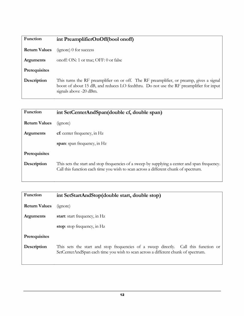
Function int PreamplifierOnOff(bool onoff)
Return Values (ignore) 0 for success
Arguments onoff: ON: 1 or true; OFF: 0 or false
Prerequisites
Description This turns the RF preamplifier on or off. The RF preamplifier, or preamp, gives a signal boost of about 15 dB, and reduces LO feedthru. Do not use the RF preamplifier for input signals above -20 dBm.
Function int SetCenterAndSpan(double cf, double span)
Return Values (ignore)
Arguments cf: center frequency, in Hz
span: span frequency, in Hz
Prerequisites
Description This sets the start and stop frequencies of a sweep by supplying a center and span frequency. Call this function each time you wish to scan across a different chunk of spectrum.
Function int SetStartAndStop(double start, double stop)
Return Values (ignore)
Arguments start: start frequency, in Hz
stop: stop frequency, in Hz
Prerequisites
Description This sets the start and stop frequencies of a sweep directly. Call this function or SetCenterAndSpan each time you wish to scan across a different chunk of spectrum.
13
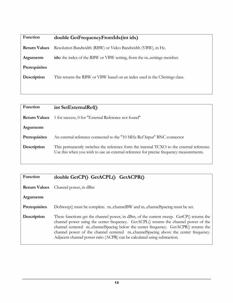
Function double GetFrequencyFromIdx(int idx)
Return Values Resolution Bandwidth (RBW) or Video Bandwidth (VBW), in Hz.
Arguments idx: the index of the RBW or VBW setting, from the m_settings member.
Prerequisites
Description This returns the RBW or VBW based on an index used in the CSettings class.
Function int SetExternalRef()
Return Values 1 for success, 0 for "External Reference not found"
Arguments
Prerequisites An external reference connected to the "10 MHz Ref Input" BNC connector
Description This permanently switches the reference form the internal TCXO to the external reference. Use this when you wish to use an external reference for precise frequency measurements.
Function double GetCP() GetACPL() GetACPR()
Return Values Channel power, in dBm
Arguments
Prerequisites DoSweep() must be complete. m_channelBW and m_channelSpacing must be set.
Description These functions get the channel power, in dBm, of the current sweep. GetCP() returns the channel power using the center frequency. GetACPL() returns the channel power of the channel centered m_channelSpacing below the center frequency. GetACPR() returns the channel power of the channel centered m_channelSpacing above the center frequency. Adjacent channel power ratio (ACPR) can be calculated using subtraction.

14
Function int DoSweep()
Return Values 0 for success, non-zero for error. The most common error is 5, USB data error, usually caused from not receiving the expected amount of data.
Arguments
Prerequisites m_settings must have the desired settings, and SetupForSweep() must be complete.
Description This function performs a sweep and fills the trace data arrays with current sweep data. The function does not return until the sweep is complete.
When complete, m_traceSize will be loaded with the trace size, where (m_traceSize / 2), discarding remainder, represents the point at the center frequency, and points, or "bins", are spaced by m_HzPerPt Hz. pDataMax will contain the maximum (or average) amplitude at each frequency, and pDataMin will contain the minimum amplitude.
Function int DoPhaseNoiseSweep(int startDecade, int stopDecade, double referenceAmplitude)
Return Values ignore.
Arguments startDecade: start at an offset from carrier of 10^ startDecade Hz.
stopDecade: stop at an offset from carrier of 10^ stopDecade Hz.
referenceAmplitude: The amplitde of the main carrier signal, used to compute
dBm/Hz.
Prerequisites A regular sweep with a narrow RBW must be performed to find the peak RF amplitude before calling DoPhaseNoiseSweep. Use SetCenterAndSpan to set the center frequency to the signal's frequency, and set referenceAmplitude to the peak amplitude.
Description This function performs a Phase Noise sweep and fills the trace data arrays with current sweep data. The function does not return until the sweep is complete.
When complete, m_traceSize will be loaded with the trace size, where each decade of offset has 100 points of data. Use the data in pDataMax only.

15
Function double ReadTemperature()
Return Values Current temperature of the Signal Hound, in degrees Celsius
Arguments
Prerequisites
Description This function reads the temperature sensor, updates the calibration corrections, and returns the temperature.
Function int DoMeasuringReceiver(MEAS_RCVR_STRUCT * pMeasRcvr)
Return Values ignore
Arguments pMeasRcvr: poiner to a structure representing the inputs and outputs of the "measuring receiver" personality of the Signal Hound.
Prerequisites The inputs of pMeasRcvr (RFFrequency, AudioLPFreq, AudioBPFreq, UseLPF, and UseBPF) must be valid.
Description This function uses the Measuring Receiver personality of the Signal Hound. Using the supplied input values, the Signal Hound digitally demodulates the incoming data, filters the demodulated "audio" using the selected filter or filters, and computes AM and FM peak and RMS modulation, as well as carrier frequency and audio frequency.
Function void * OpenAudio()
Return Values a pointer to a CAudioStream object. Save this pointer and use it when calling ReadAudioChunk and CloseAudio.
Arguments
Prerequisites Set CSettings::m_decimation to the desired decimation (IF bandwidth) setpoint.
Description This function uses the current center frequency and begins to stream demodulated audio data to the application. Do not call this function until you are ready to continuously poll CAudioStream::ReadAudioChunk to acquire the demodulated 16-bit audio. The demodulation mode defaults to FM, but can be changed by setting CAudioStream::m_demodMode
16
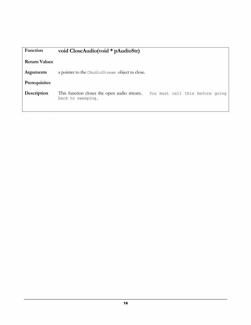
Function void CloseAudio(void * pAudioStr)
Return Values
Arguments a pointer to the CAudioStream object to close.
Prerequisites
Description This function closes the open audio stream. You must call this before going
back to sweeping.

17
Important variables in the CMySignalHound class
Member Variable Description
m_settings CSettings class. Encapsulates the Signal Hound settings
pDataMax Trace Data Array. An array of up to 32768 points of trace data maximums (or averages). Linear, milliwatt units.
pDataMin Trace Data Array. An array of up to 32768 points of trace data minimums (or averages). Linear, milliwatt units.
m_HzPerPt Hz per point, offset from center frequency at (m_traceSize / 2)
m_traceSize Trace size. pDataMax and pDataMin each have this many elements after DoSweep() is called.
m_BBSPSetpt 1, 2, or 5 (MHz)
m_serialNumber 8 digit serial number
m_channelBW For channel power, channel bandwidth in Hz
m_channelSpacing For channel power, channel spacing in Hz
m_idxOfMinRBW For any given span, these variables will be set after a call to SetupForSweep(). These indexes represent the minimum and maximum RBW settings for a given span, to keep trace size to a manageable level. m_idxOfMaxRBW
18
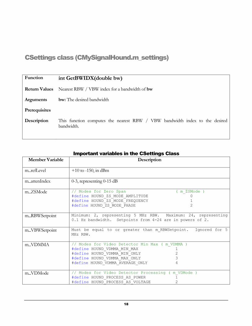
CSettings class (CMySignalHound.m_settings)
Function int GetBWIDX(double bw)
Return Values Nearest RBW / VBW index for a bandwidth of bw
Arguments bw: The desired bandwidth
Prerequisites
Description This function computes the nearest RBW / VBW bandwidth index to the desired bandwidth.
Important variables in the CSettings Class
Member Variable Description
m_refLevel +10 to -150, in dBm
m_attenIndex 0-3, representing 0-15 dB
m_ZSMode // Modes for Zero Span ( m_ZSMode )
#define HOUND_ZS_MODE_AMPLITUDE 0
#define HOUND_ZS_MODE_FREQUENCY 1
#define HOUND_ZS_MODE_PHASE 2
m_RBWSetpoint Minimum: 2, representing 5 MHz RBW. Maximum: 24, representing
0.1 Hz bandwidth. Setpoints from 4-24 are in powers of 2.
m_VBWSetpoint Must be equal to or greater than m_RBWSetpoint. Ignored for 5
MHz RBW.
m_VDMMA // Modes for Video Detector Min Max ( m_VDMMA )
#define HOUND_VDMMA_MIN_MAX 1
#define HOUND_VDMMA_MIN_ONLY 2
#define HOUND_VDMMA_MAX_ONLY 3
#define HOUND_VDMMA_AVERAGE_ONLY 4
m_VDMode // Modes for Video Detector Processing ( m_VDMode )
#define HOUND_PROCESS_AS_POWER 1
#define HOUND_PROCESS_AS_VOLTAGE 2

19
#define HOUND_PROCESS_AS_LOG 3
#define HOUND_PROCESS_BYPASSED 4
m_RBWIsAuto default: true. When true, RBW is automatically updated when span is updated
m_VBWIsAuto default: true. When true, VBW is automatically updated when span is updated
m_SWPTMSetpoint Set to 0 (prefer fast sweeping with short acquisitions) thru 3 (prefer slow sweeping with long acquisitions). Allows users to select longer acquisitions to catch intermittent events.
m_suppressImage When set to true, two acquisitions will be masked together to reject image and spurious signals for a continuous narrow-band signal. When set to false, the image response is not masked out at all.
m_decimation Decimation setpoint. Automatically controlled for span > 0.
#define HOUND_IFBW_240kHz 1
#define HOUND_IFBW_120kHz 2
#define HOUND_IFBW_60kHz 4
#define HOUND_IFBW_30kHz 8
#define HOUND_IFBW_15kHz 16
m_sweepMode // Sweep Modes ( m_sweepMode )
#define HOUND_SWEEP_MODE_SLOW_SWEEP 0
#define HOUND_SWEEP_MODE_FAST_SWEEP 1
#define HOUND_SWEEP_MODE_RBW_5MHz 2
#define HOUND_SWEEP_MODE_ZERO_SPAN 3
#define HOUND_SWEEP_MODE_TRACK_GEN 5
#define HOUND_SWEEP_MODE_PHASE_NOISE 7
#define HOUND_SWEEP_MODE_BB_SIG_PEAK 9
m_ZSSweepTime Zero Span Sweep time setting, in seconds.
m_ZSMode // Modes for Zero Span ( m_ZSMode )
#define HOUND_ZS_MODE_AMPLITUDE 0
#define HOUND_ZS_MODE_FREQUENCY 1
#define HOUND_ZS_MODE_PHASE 2

20
MEAS_RCVR_STRUCT
INPUTS
RFFrequency center frequency of modulated signal
UseLPF Set to 'true' to filter audio through the selected low pass filter
AudioLPFreq Low pass filter cutoff frequency
UseBPF Set to true to filter audio through the selected bandpass filter.
AudioBPFreq Center frequency for the audio bandpass filter. This filter has a bandwidth of approximately 160 Hz
OUTPUTS
RFCounter The actual RF frequency detected within the selected IF passband
AMAudioFreq The frequency of the amplitude-modulated audio tone, if any
FMAudioFreq The frequency of the frequency-modulated audio tone, if any
RFAmplitude The average amplitude, in dBFS (dB down from Full Scale)
FMPeakPlus,
FMPeakMinus,
FMRMS
The results of FM demodulation. PeakPlus represents the most positive frequency offset. PeakMinus represents the most negative frequency offset. RMS represents the root mean square offset. For a sinusoid, the RMS value will be 0.707 times the Peak value.
AMPeakPlus,
AMPeakMinus,
AMRMS
The results of AM demodulation. PeakPlus represents the most positive amplitude offset, in percent. PeakMinus represents the most negative amplitude offset, in percent. RMS represents the root mean square offset. For a sinusoid, the RMS value will be 0.707 times the Peak value.

21
CAudioStream Class
Function int ReadAudioChunk(short * buffer)
Return Values ignore
Arguments Pointer to an int16 buffer.
Prerequisites CMySignalHound::OpenAudio must be used to create a pointer to an audio stream
Description This function reads I/Q data from the Signal Hound, demodulates the audio and loads it into this buffer. 4K samples (4096 samples, or 8192 bytes) will be loaded.
Important variables in the CAudioStream Class
Member Variable Description
m_demodMode #define DEMOD_MODE_AM 0 //Amplitude modulation
#define DEMOD_MODE_FM 1 //Frequency modulation
#define DEMOD_MODE_USB 2 //Single sideband (upper sideband)
#define DEMOD_MODE_LSB 3 //Single sideband (lower sideband)
#define DEMOD_MODE_CW 4 //Continuous Wave / Morse Code
Miscellaneous Functions (no class)
Function double mW2dBm(double mWIn)
Return Values RF Power, in dBm
Arguments mWIn : RF Power, in mW
Prerequisites
Description This function converts milliwatts to dBm

22
Function double GetRBWFromIndex (int idx)
Return Values Resolution bandwidth, in Hz
Arguments idx : index of RBW or VBW, from usually from CSettings::m_RBWSetpt
Prerequisites
Description This function converts milliwatts to dBm
ERROR CODES
Error Code Meaning
0 No error.
1 No Signal Hound found. The FTDI driver scanned the USB ports for a "Signal Hound" device and found none.
2 Signal Hound Port did not open. The FTDI driver found a Signal Hound, but was unable to open its "ports" for data i/o.
4 Unexpected (leftover) USB data
5 Missing USB Data
8 IF level too high - possible compression warning
98 Signal Hound temperature correction file, "D<serial number>.bin", was not found.
99 Signal Hound calibration constants file, "<serial number>.tep", was not found.