test grains as a novel diagnostic tool b.w. james, a.a. samarian and w. tsang school of physics,...
TRANSCRIPT

TEST GRAINS AS A NOVEL DIAGNOSTIC TOOL
B.W. James, A.A. Samarian and W. Tsang
School of Physics, University of Sydney
NSW 2006, [email protected]
ICPP Sydney 2002
What is a dusty plasma?
• a low temperature plasma containing small particles of diameters in nanometer and micrometer range
• particles acquire a net negative charge (at equilibrium floating potential)
• particles levitated in sheaths where electric force balances gravity
• particles can form liquid- and solid- like arrays (plasma or Coulomb crystal) which can undergo phase transitions

Forces on dust particle in plasma sheath
E
vi
rf powered electrode
radius = acharge = Zd
sheathboundary
heq
hb
FE, Fth
Fg, Fi
ions
z
Figure 1: Schematic diagram of dust particle in plasma sheath
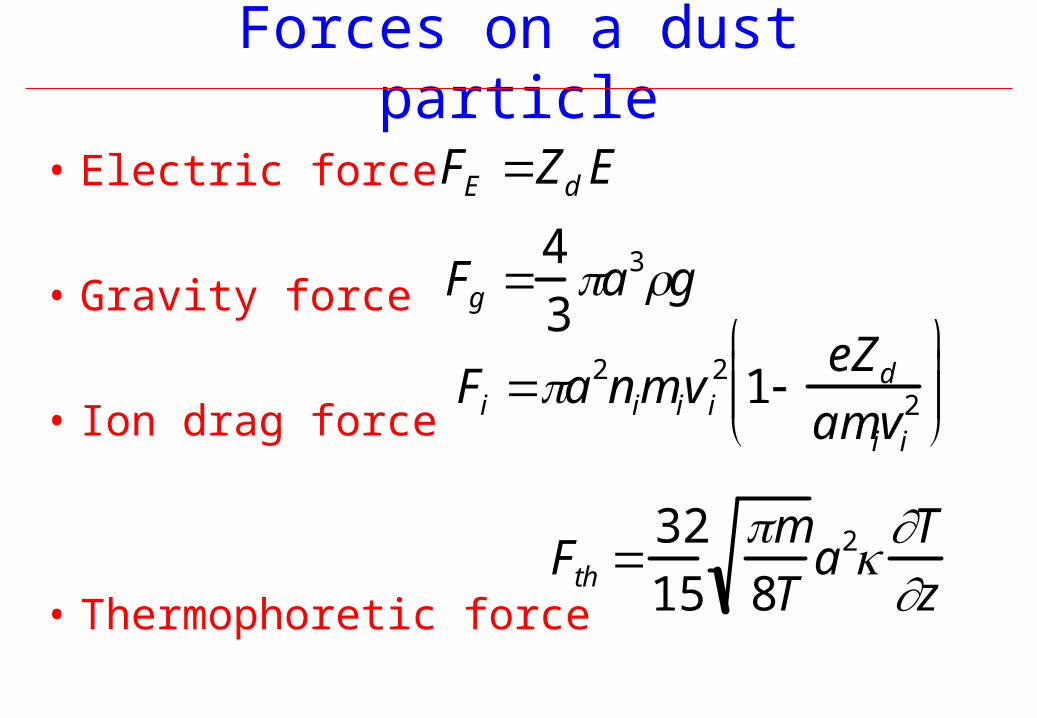
Forces on a dust particle
• Electric force
• Gravity force
• Ion drag force
• Thermophoretic force
FE Zd E
Fg 4
3a3g
Fi a2nimiv i2 1
eZ d
amivi2
Fth 32
15
m
8Ta2
T
z
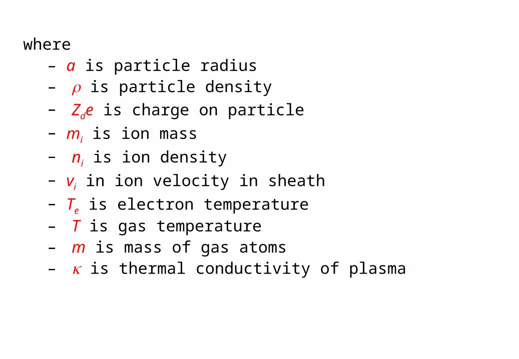
where– a is particle radius– is particle density– Zde is charge on particle– mi is ion mass– ni is ion density– vi in ion velocity in sheath– Te is electron temperature– T is gas temperature– m is mass of gas atoms– is thermal conductivity of plasma

Experimental arrangement
Dust particles
Grounded electrode
Powered electrode
Figure 2: Experimental chamber and image of test dust particles levitated above the electrode. The test grains are generated in the discharge (power up to 200W, pressure up to 1 torr) by electrode sputtering.

Equilibrium position of dust particleUsing the force balance equation,
FE + Fg + Fi + Fth = 0 the equilibrium position has been calculated as a
function of radius a (see figure 3) using following assumptions– Vs ~ 60 V, linear variation of electric field in sheath– vi from sheath model– Te ~ 2 eV– R = 2 g cm-3
– dT/dz ~ 1-5 K cm-1 (varying with input power)– Zd calculated from OML theory
Equilibrium position vs. radius
0
0,1
0,2
0,3
0,4
0,5
0 0,5 1 1,5 2 2,5 3
Dust radius, m
(hb-heq)/hb
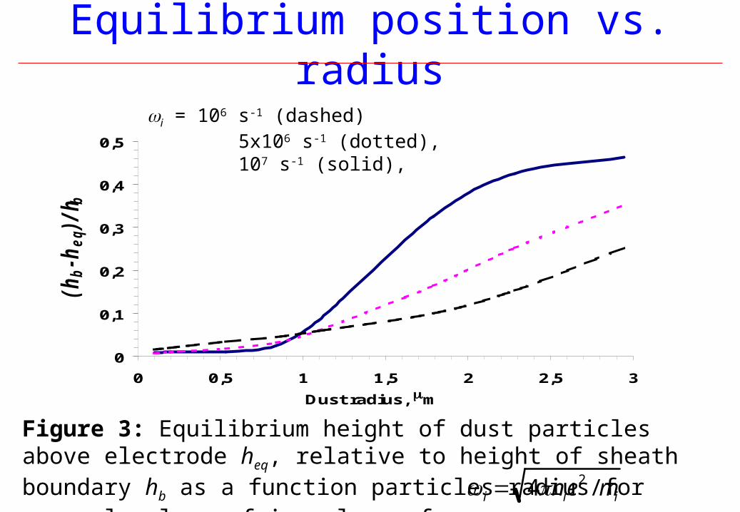
Figure 3: Equilibrium height of dust particles above electrode heq, relative to height of sheath boundary hb as a function particles radius for several values of ion plasma frequency,
i = 106 s-1 (dashed) 5x10⁶ s-1 (dotted), 107 s-1 (solid),
i 4nie2 / mi
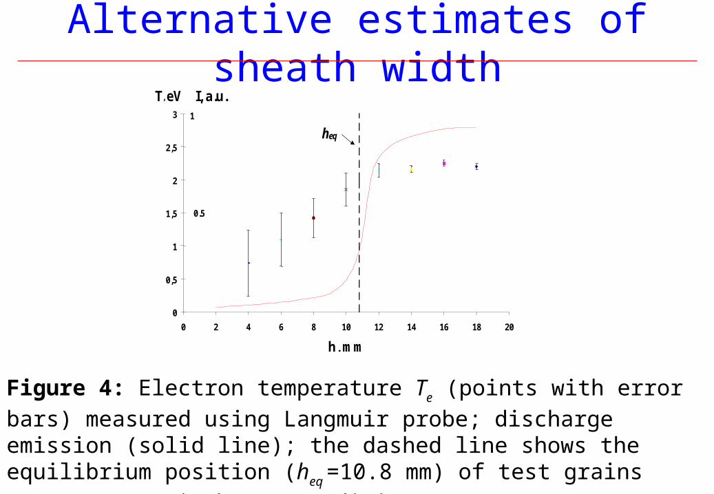
Alternative estimates of sheath width
0
0,5
1
1,5
2
2,5
3
0 2 4 6 8 10 12 14 16 18 20
h, mm
T, eV I, a.u.1
0.5
heq
Figure 4: Electron temperature Te (points with error bars) measured using
Langmuir probe; discharge emission (solid line); the dashed line shows the equilibrium position (heq =10.8 mm) of test grains (a~350 nm). Discharge
conditions: p = 90m Torr, P = 80 W.

0
5
10
15
20
25
30
0 10 20 30 40 50 60 70 80 90 100
Pressure (mTorr)
hb(mm)
Position of sheath edge (Position of sheath edge (hhbb) vs pressure at different rf-input powers) vs pressure at different rf-input powers
– 35W
– 60W
– 100W
Sheath width as function of pressure

Visualisation of rf sheath
• Sufficiently small particles cannot achieve force equilibrium in the sheath - the sheath becomes a particle-free region
• Particles occupy pre-sheath and positive column
• Provides a visualisation of the sheath-plasma boundary - see Figure 5
Figure 5:The shape of the potential well above the confiningelectrode in a radio-frequency (rf) discharge with aprinted-circuit board electrode system (Cheung et al.,2002) was visualised using fine dust grains that weregenerated in the discharge. The well shape wasfound to depend strongly on the confining potential
QuickTime™ and aPhoto - JPEG decompressor
are needed to see this picture.

Particle Particle Driving PadDriving Pad
ParticleParticleDispenserDispenser
Top GroundTop GroundElectrodeElectrode
Gas InletGas Inlet
RF Supply15MHz
AC PowerPin ElectrodesPin Electrodes
DC Power
Side ObservationSide ObservationWindowWindow
Top ObservationTop ObservationWindowWindow
dZ
svFsvFsma 2211 )()(
1s2s
a
1v2v
vavmnFnTn
2
3
4
Transient motion technique
where
)(rf
Top View
'
20 )2(
E
mfZD
0fWhere is the resonant frequency'EAnd is the electric field gradient
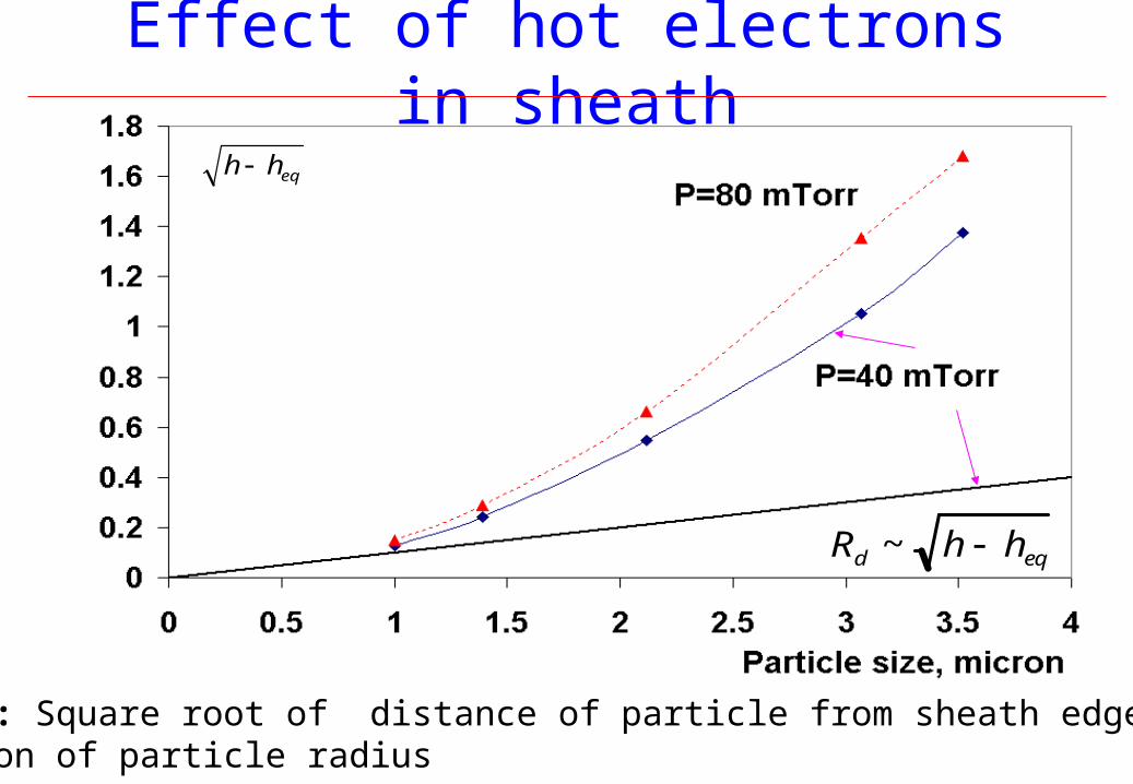
Effect of hot electrons in sheath
Rd ~ h heq
eqhh
Figure 6: Square root of distance of particle from sheath edge as a function of particle radius


Particle Data
Probe Data
Figure 7: Potential profile measured by a Langmuir probe, and by transient motion analysis
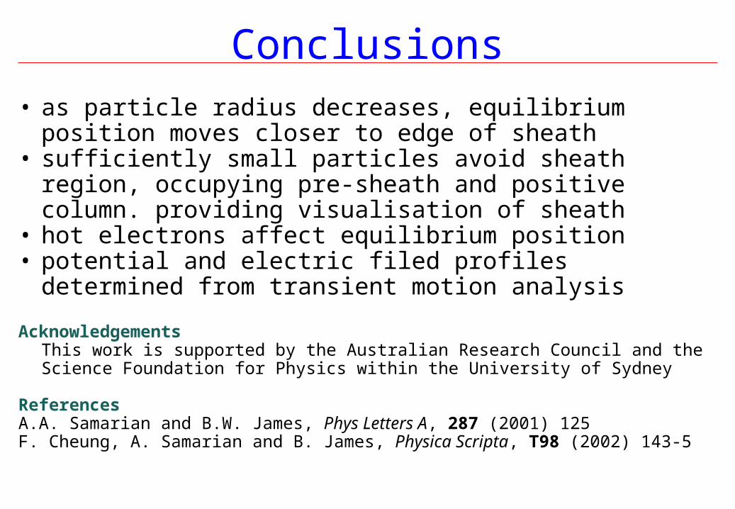
Conclusions
• as particle radius decreases, equilibrium position moves closer to edge of sheath
• sufficiently small particles avoid sheath region, occupying pre-sheath and positive column. providing visualisation of sheath
• hot electrons affect equilibrium position• potential and electric filed profiles determined from transient
motion analysis
AcknowledgementsThis work is supported by the Australian Research Council and the Science Foundation for Physics within the University of Sydney
ReferencesA.A. Samarian and B.W. James, Phys Letters A, 287 (2001) 125F. Cheung, A. Samarian and B. James, Physica Scripta, T98 (2002) 143-5

Particle Data
Probe Data
Least Mean Square Fit for Particle Data
Least Mean Square Fit for Probe Data
Figure 8:Radial electric fieldderived from resultsin figure 7.