test methodology to evaluate the safety of materials using ... · test methodology to evaluate the...
TRANSCRIPT
Test Methodology to Evaluate the Safety of Materials
using Spark Incendivity
Charles Buhler (1), Carlos Calle (2), Sid Clements (3), Mindy Ritz (1), Jeff Starnes (1)
(1) Electrostatics and Surface Physics Laboratory, ASRC Aerospace, Kennedy Space Center, FL 32899, USA
tel.: 321-867-4861, fax: 321-867-4489, e-mail: BuhleCR(äkscems.ksc.nasa.gov
(2) Electrostatics and Surface Physics Laboratory, NASA, Kennedy Space Center, FL 32899, USA
tel.: 321-867-3274, fax: 321-867-4489, e-mail: carlos.i.calle(nasa.gov
(3) Department of Physics and Astronomy, Appalachian State University, Boone, NC 28608, USA
tel.: 868-262-2447, fax: 828-262-2049, email: c1ementsjs(apptate.edu
Abstract - For many years scientists and engineers have been searching for the proper test method to evaluate
an electrostatic risk for materials used in hazardous environments. A new test standard created by the
International Electrotechnical Commission is a promising addition to conventional test methods used
throughout industry. The purpose of this paper is to incorporate this test into a proposed new methodology for
the evaluation of materials exposed to flammable environments. However, initial testing using this new
standard has uncovered some unconventional behavior in materials that conventional test methods were thought
to have reconciled. For example some materials tested at higher humidities were more susceptible to incendive
discharges than at lower humidity even though the surface resistivity was lower.
I. Introduction
The NASA Kennedy Space Center (KSC) uses a variety of materials in hazardous spaceport operations. Before
materials can be used they must first pass a battery of tests that includes flammability, hypergolic compatibility
https://ntrs.nasa.gov/search.jsp?R=20130012996 2018-05-30T05:37:07+00:00Z

• and electrostatics. KSC uses Standard Test Method MMA-1985-79 for evaluating the electrostatic properties of
materials [1]. The test, which will be described in detail later, is a triboelectric charge decay test that evaluates
the electrostatic properties of the test materials and provides a pass/fail criterion for candidate materials. This one
simple test is all that is currently used to fully evaluate the electrostatic properties of spaceport materials.
KSC uses a variety of hazardous chemicals and flammable materials during normal operations. Safety of the
workers is a prime concern. The question of the proper techniques that should be utilized to evaluate electrostatic
hazards has been debated for a long time and it is not clear that simple triboelectric testing alone suffices.
Therefore, what follows is a new evaluation criteria for the proper selection of materials used during hazardous
operations.
II. Proposed Evaluation Criteria
Before discussing the proposed test methodology it is important to discuss the relevant factors that can cause
incendiary discharges. Incendiary discharges are prominent in materials possessing high surface voltages as a
result of significant surface charge. The risk of occurrence of incendiary static discharges depends primarily on
the energy liberated which is influenced by the gap size, geometry of the system, mobility of the charge, duration
of the discharge, etc. Therefore, an understanding of the electrostatic properties of a material is useful in
determining how it might behave in a flammable environment. What follows is a proposed test method based on
conventional methods currently used to classify materials (presented here for review) with the addition of two
new tests resulting in a vigorous yet realistic evaluation scheme for the sole purpose of identifying materials that
could be hazardous in flammable environments.
The first step in evaluating the electrostatic characteristics of a material is to classify the material in terms of its
conductivity. If materials are conductive or statically dissipative, then these materials must be electrically bonded
to ground in all cases so that any electrostatic charge generated or deposited on them has an electrical path to
ground. Depending on the nature of the material and its usage, no further testing is needed if the material can be
iø loll
grounded. However, if the materials are insulating, further testing such as charge decay tests should be
performed. Charge decay tests are tests in which electrostatic charge is placed on the surface of a material and the
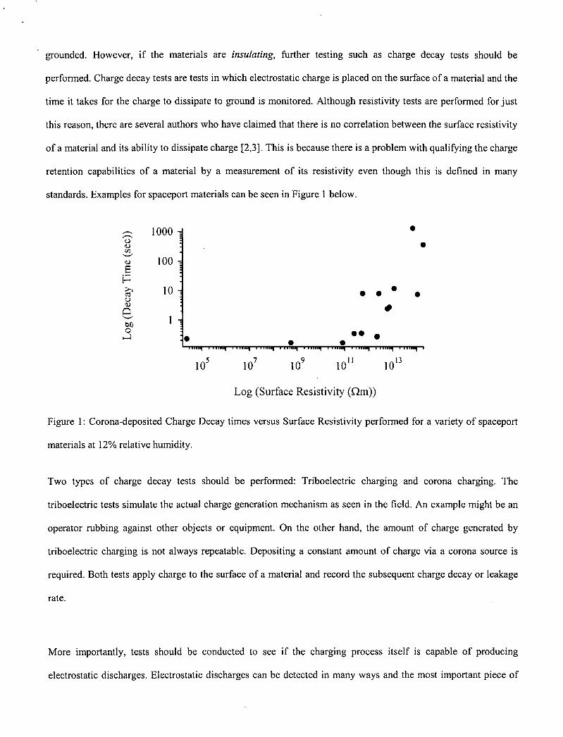
time it takes for the charge to dissipate to ground is monitored. Although resistivity tests are performed for just
this reason, there are several authors who have claimed that there is no correlation between the surface resistivity
of a material and its ability to dissipate charge [2,3]. This is because there is a problem with qualifying the charge
retention capabilities of a material by a measurement of its resistivity even though this is defined in many
standards. Examples for spaceport materials can be seen in Figure 1 below.
1000 0
100
H10
0
C
Log (Surface Resistivity (Qm))
Figure 1: Corona-deposited Charge Decay times versus Surface Resistivity performed for a variety of spaceport
materials at 12% relative humidity.
Two types of charge decay tests should be performed: Triboelectric charging and corona charging. The
triboelectric tests simulate the actual charge generation mechanism as seen in the field. An example might be an
operator rubbing against other objects or equipment. On the other hand, the amount of charge generated by
triboelectric charging is not always repeatable. Depositing a constant amount of charge via a corona source is
required. Both tests apply charge to the surface of a material and record the subsequent charge decay or leakage
rate.
More importantly, tests should be conducted to see if the charging process itself is capable of producing
electrostatic discharges. Electrostatic discharges can be detected in many ways and the most important piece of

information gathered is whether the discharges are capable of igniting a flammable atmosphere. Accurate
measurement of the total energy in a discharge is nearly impossible because the energy may be released in
various forms. Discharge energy is released as thermo molecular motion of the air atoms in the form of heat and
sound, and as transitional energy of the atomic states in the form of light and electromagnetic waves. Thus
capturing all of the forms of energy simultaneously is highly impractical. Ignition also depends on more than total
energy; the spatial and temporal distributions of the electrostatic discharge also affect ignition. For example, if
the discharge is diffuse or if the discharge occurs slowly, then the energy density may be too low for ignition to
occur.
It is difficult to measure how concentrated the electrostatic discharge is and thus it is only feasible to measure the
total electrical energy of the discharge. Instead, one can measure a certain characteristic of the energy of interest
such as the total amount of charge exchanged. The electrical energy portion of the discharge is well known as
Q212C, where Q is the total charge and C is the capacitance of the gap. Forcing a discharge through a gas to
produce ignition is a commonly used method to calculate the Minimum Ignition Energies (ME) of the gas.
Likewise limitations of discharge energies can be measured by immersing the spark-gap in a gas of known ME.
This method for measuring discharge energies serves as the basis for the new Spark Incendivity Test Standard
[4]. Charge is placed onto a material using either tribo or corona methods and extracted with a grounded metal
probe. As the probe nears the test material it will discharge an area of the charged surface. Gases of known ME
flow between the probe and the charged test sample. If the electrostatic discharge energy is sufficient and the
probe is placed greater than the quenching distance, an ignition will occur. If charge placed on the test material is
capable of sustaining an incendive discharge the material should not be used.
The user may want to still use the material if it fails the Spark Incendivity Test. This is not unreasonable since the
extreme charging method used deposits significant charge on the surface of the test materials which may be
considered unrealistic in the field. Therefore a more realistic test would be one which is performed exactly as in
the workplace and the conditions replicated. For example, if it is known that a certain material is to be detached
from another at high speeds and there is a possibility for a flammable gas to be present, tests should be performed
inside a controlled environment that simulates this exact process. This test, which on average produces far less
electrostatic charge on insulator surfaces than Spark Incendivity, is called "representative testing".
Although the above Spark Incendivity test procedure measures whether extreme amounts of deposited charge is
capable of igniting a gas mixture of known MIE, there are limitations to this test method. The prime limitation is
that the charge generation occurs before electrostatic discharge measurements are made rather than
simultaneously. The test samples are charged in air first before the probe and its gas mixture of known ME
approaches the surface. Since the material is charged in air, the maximum amount of charge on the surface is
limited by air breakdown. During separation, triboelectric charging is capable of depositing significant amounts
of charge on surfaces well above the breakdown of air but as the surfaces separate, the amount of charge will be
limited by gas breakdown if the surface electric fields produced are in excess of 3x10⁶ V/rn. The initial
breakdown itself will be in the form of a spark or corona that is not measured using Spark Incendivity.

Test Material
Surface Corona Charge Tribo Charge
Resistivity Decay Decay
Pass Fail Pass Fail Pass Fail
Ground Test Spark Incendivity Material Test
Pass I Fail
Representative Tests in a
Flammable Atmosphere
Pass Fail
Use Material Do Not Use Material
Figure 2: Proposed test method to evaluate the ESD safety of materials used in flammable environments.
Representative testing is capable of capturing this behavior since the triboelectrification and separation occurs in
the flammable environment. Thus one might suggest performing representative testing before Spark Incendivity
to capture this potentially large discharge event. However Spark Incendivity is a simpler test that deposits
significant charge that can be performed quickly while Representative testing requires blast-proof chambers and
cannot be performed easily. In the end it is user discretion as to the appropriate methodology to choose based on
the material and the environment it is to be used in. For example, clothing materials may be more susceptible to
high levels of sustained charge for longer periods of time ideally tested for Spark Incendivity, while a high-speed
insulating belt over a grounded metal roller in the presence of a flammable atmosphere would not benefit greatly
from a Spark Incendivity test.

The complete test methodology for evaluating the ESD safety of materials particularly associated with spaceports
is shown in Figure 2. The next section describes measurement techniques used to evaluate the proposed test
method followed by experimental cases used to evaluate typical spaceport materials.
A. Surface Resistivity
The first series of tests consisted of measuring the surface resistivity of the materials. Surface resistance
measurements are the main test method used in industry to characterize the ESD properties of materials, since it
is generally believed that charge deposited onto the surface of a material will "leave" (or decay) easier from a
material with lower surface resistance than from a material with high surface resistance. Materials with a surface
resistance less than I 0 1) are considered conductive. Materials between 1 and 101 I are statically
dissipative and materials with a surface resistance above 1011 1 are insulating according to ANSIIESD standards.
Surface resistivity is the ratio of the DC voltage to the current flowing between two electrodes of specified
configuration that contact the same side of the material and is expressed in ohms (a). The surface resistivity tests
were performed per the requirements of the ESD Association Standard Test Method ESD STM 11.11 [5]. These
measurements were taken using a PRS-80 1 resistance system with an Electro Tech System (ETS) PRF-9 11
concentric ring resistance probe with up to 100 volts applied between the electrode and ground. The tests require
a five pound weight on top of cylindrical electrodes and were conducted at both 20% ± 5% relative humidity and
50% ± 5% relative humidity. In order for materials to pass resistivity tests, the surface of the materials must
either be conductive or statically dissipative. Otherwise the materialsfail the ESD test.
B. Triboelectric Charging
One method of charging a material is by contact (triboelectric) charging. The Electrostatics and Surface Physics
Laboratory at KSC has been performing triboelectric charging tests of materials for over forty years. The
Kennedy Space Center uses Standard Test Method MMA-1985-79 entitled "Standard Test Method for Evaluating
Triboelectric Charge Generation and Decay" [1]. This method of evaluating the electrostatic properties of

BLJER MOTOR HEAD
STATIC iiI ; DETECTOR HEAD
SAMPLE CARRIER SHUTTLE
ESO ROBOT 4.
materials records the charge decay after the test material is rubbed with either wool or PTFE felt. A device called
the ESD Robot used to test materials is shown below in Figure 3.
Two seven-inch square test samples were cut out of each of the stock materials to be tested. They were then
mounted onto an aluminum frame and acclimated at 75°F for 24 hours prior to testing under relative humidities
of 45% and 30% compliant with the current KSC standard. The aluminum frames were then mounted on the
sample carrier shuttle that operates in two positions. The first position allows a PTFE felt disk or wool disk
(about five inches in diameter) to rub against the test sample using five pounds of force. The disk rotates at 400
revolutions per minute for ten seconds to "saturate" the sample with charge. After ten seconds the sample moves
into the second position in front of a static detector head that records the surface potential while the aluminum
frame is grounded. Shown in Figure 3 is the Keithley model 2501 Static Detector head. However, here we used
JCI model 140 Static Monitor with a guard to record surface potential. The current KSC standard dictates that
materials pass the ESD test criteria if the surface voltage is below 350 volts after five seconds, otherwise the
materialsfai/.
SAMPLE CARRIER RACA W SAMPLES
-I
p • • .•-4,
Figure 3: Triboelectric ESD Robot at the NASA Kennedy Space Center.

fieldinet sensing aperturi
noving plate
C. Corona Charging
The next battery of tests conducted on spaceport materials is corona charge decay. Corona charge deposition is
chosen because surface charge levels can be deposited in a controlled manner. Tests are performed using a JCI
155v5 Charge Decay Test Unit conforming to British Standard 7506 "Methods for Measurements in
Electrostatics" [6]. This device deposits a consistent amount of negative charge onto the surface of a material by
ionizing the air molecules with high voltage corona needle points up to ±10,000 volts [Figure 4]. Materials that
have been acclimated at Once mounted, the materials were acclimated at both 20% ± 5% relative humidity and
50% ± 5% relative humidity are placed inside the JCI 176 Charge Measurement Sample Support system. The JCI
I 55v5 sits on top of a JCI 176 system which has the ability to measure the total amount of charge transferred to
the sample [Figure 5]. The total amount of charge transferred to the sample consists of both the charge that
"leaves" the surface of the sample and the charge that remains. The samples are mounted between two
conducting plates shown in Figure 5.
discharge points
Figure 4: The JCI 155v5 Charge Decay Test Unit.

JCI 155 Charge Decay Test Unit fleidmeter sensing aperture
insulation betweenmoving plate with cluster
plates and JCI 155L_1 of corona discharge points
air dam
shielding box'induction sensing electrode
conduction charge measuring mounting plates
Figure 5: JCI 155v5 sits on top of the JCI 176 Charge Measurement Sample support.
Once the charge is deposited onto the surface of the test material, the plate containing the corona points is
retracted (within 20 ms) and a fieldmeter is exposed. This fieldmeter measures and records the surface potential
on the material as a function of time. The time it takes for the surface voltage to reach l/e (1/2.72) or 37% of its
maximum value is called the decay time or t. For materials to possess "good" ESD behavior, they should
dissipate the charge faster than one could deposit it in the field. Decay times as short as 0.2 seconds have been
quoted for materials to dissipate charge satisfactorily [7], however here we use the criteria that decay times be
less than one second.
D. Spark Incendivity Testing
If the materials fail any of the above three tests, they will be subjected to a new test based on Spark Incendivity
Testing, a new International Standard being created by the International Electrotechnical Commission (IEC)
entitled, "Electrostatic Classification of Flexible Intermediate Bulk Containers (FIBC)" [4]. This test method has
been successful for evaluating the safety of FIBC which are widely used for the storage, transportation and
handling of powdered, flaked or granular material throughout industry. The mishandling, improper grounding,
and poor electrostatic dissipation properties of FIBC has led to several hazardous events which have in some
cases caused injury and/or death to workers.

The use of the new IEC test standard should greatly decrease the number of incidents by addressing the ESD
hazard properly. Essentially, the test method is to charge a material either by corona charging andlor triboelectric
charging and then purposely discharge the surface of the test material (in the form of a spark) using a metal
sphere while in the presence of a flammable gas mixture. If the energy of the spark has at least the energy equal
to the minimum ignition energy (Mifi) of the gas mixture, then the resulting discharge will be capable of igniting
the gas mixture. This test method directly measures a material's propensity to deliver sufficient ignitable charge
from its surface when a worker andlor object is nearby.
To perform this test, a Spark Incendivity Probe (SIP) is used. A schematic of this probe is shown in Figure 6.
Gases with a known MIE enter into a polycarbonate mixing chamber full of glass beads to ensure uniform mixing
and to serve as a flame arrestor to prevent back propagation. The gas mixture passes first through fine copper
mesh and then into the mixing chamber before passing through a second copper mesh and a perforated metal
plate. The gases then surround the electrically grounded brass electrode (with guard) and ignitions occur between
the electrode and the charged surface.
The proposed test standard normally calls for gas mixtures of 5.4% ethylene in air, which has an MIE of 0.14 mJ.
This is the MIE of methanol environments that are the worst case for FIBC normally seen in industry. Here
however, testing was performed using hydrogen in air at stoichiometric mixtures (30% H 2 and 70% dry air as
before) having a much lower MIE of 0.02 mJ to represent the worst-case scenario of a charged material in the
presence of a hydrogen-enriched atmosphere. Hydrogen and other flammable gases and liquids are commonly
used in spaceport operations hence electrostatic charging could pose a problem if incendive discharges exist.
Tribocharging occurs in several ways and can be due to charged personnel, charged payloads or equipment, and
charged liquids and vapors during typical orbiter processing and operations.

14 2cm,!
Guarded
Probe
Metal Plate
f 10cm
Glass Beads
Figure 6: Schematic of the Spark Incendivity Probe [4].
Samples are typically mounted on an insulating frame using clips. Once mounted, the materials were acclimated
for up to two days at both 20% ± 5% relative humidity and 50% ± 5% relative humidity. Charge was applied to
the materials in two ways. The first method was corona charging. A high-voltage power supply was connected to
a corona needle plate to creates ions in the air that deposit onto the surface of the test material. The voltage was
set to -30kv to deposit charge levels similar to what is seen in FIBCs. The second method to apply charge to the
materials was by tribocharging with wool. The wool cloth was repeatedly rubbed by hand against the test
materials until they were saturated with charge. After the charge deposition onto the surface, the resulting surface
potential was measured using a JCI 140 Fieldmeter and recorded. After the test material is fully charged, the gas
mixture is allowed to flow through the probe for at least 30 seconds. The probe then approaches the charged
material with the speed of approach of about (0.75 ± 0.25) rn/s. Too slow an approach would cause corona to
reduce local charge levels and too fast an approach would cause quenching of the nascent flame kernel. The
probe approached the surface in five locations per test and there were at least 25 charging tests giving a total of

125 approaches per unique environmental condition. Tests were performed at two humidities, using two charging
mechanisms and on both sides of the material yielding a total of 1000 tests per sample.
There was simultaneous charge measurements performed during the Spark Incendivity Testing using a
guardlelectrode geometry. The amount of charge exchanged during electrostatic discharges was measured by
connecting the electrode to a large capacitor whose voltage was monitored. In the case that the extracted charge
was sufficient to cause an ignition of the hydrogen-air mixture, the ignition event was recorded as a failure.
E. Representative Tests
Normally, Spark Incendivity is the final step in the selection of a candidate material for use in a possible
flammable atmosphere since this method provides sufficient charge that can be extracted from it to create an
incendive event. However, if the materials fail this test and no other material is available to replace it, then
"representative testing" is required. Unlike Spark Incendivity testing that deposits a signfi cant amount of charge
on the test material, representative testing deposits a realistic amount of charge on the materials by simulating its
actual usage in the field. If the highest charging mechanism is identified and replicated, then it is possible to
experimentally reproduce this scenario whilst immersed in a worst-case flammable atmosphere. If the charging-
discharging of the test materials does not ignite the flammable atmosphere, then and only then can the materials
be deemed safe as they are. Otherwise the materials must not be used if a single ignition event occurs. Here each
test must be designed and conducted careftilly to ensure that the materials are evaluated properly. Tests of this
nature require an Incendivity Chamber capable of mounting the test material and reproducing exactly the realistic
charging mechanism. The major difficulty with this test method resides in the correct the number of tests to be
taken. Too few tests performed results in statistical uncertainties when trying to compute the probability of an
incendive event occurrence. Thus it is better to not use the material at all and avoid representative testing if
possible. Such discussions are beyond the scope of this paper but these tests have been performed by the ESPL.
Results on "Representative Testing" are presented elsewhere [8-10].

III. Results
Table 1: Test Results of Selected Materials
__________________
Surface Resistivity (ohms)
Corona Charge Decay Time _______ _(ec)
Tribo Charge Decay Time J!ec) _______
Spark Incendivity
50%RH 20%RH 50%RH P/F 20%RH
-
P/F 45%RH P/F 30%RH P/F
_______
50%RH
_______
20%RH
Chioroprene 6.75E+11 4.19E+12 0.351 P 0.436 P 0.454 P 1.04 P P P
VFH Copolymer 2.63E+12 1.34E+12 7.96 F 10.2 F 12.9 F 23.1 F P P
Chlorobutyl-coated Nomex fabric 3.85E+12 1.09E+13 >5mm F >5 mm F >5 mm F >5 mm F P P
Bromobutyl 9.62E+12 1.97E+12 32.1 F 33.3 F 45.0 F 78.0 F P P
HDPE fibers 1.73E+13 2.40E+13 >5mm F >5mm F >5 mm F >5 mm F P P
Metallized PTFE 1 4.57E+11 2.80E+12 >5 mm F >5 mm F >5 mm F >5 mm F F P
Metallized PTFE 2 1.52E+11 5.47E+11 >5 mm F >5 mm F >5 mm F >5 mm F P F
PTFE-coated fiberglass 1.20E+14 8.70E+12 >5 mm F >5 mm F >5 mm F >5 mm F P P
Laminated fabric 3.20E+10 3.28E+11 0.27 P 0.63 P 0.561 P 1.0 P P P
polyvinylchioride 2.40E+13 5.04E+13 >5 mm F >5 mm F >5 mm F >5 mm F F P
polycarbonate 6.32E+13 1.22E+13 >5 mm F >5 mm F >5 mm F >5 mm F F P
nylon 1.78E+12 1.06E+11 0.593 P 1.71 F 1.15 F 2.73 F P P
PTFE-coated fabric 3.66E+11 1.82E+12 0.167 P 1.09 F 0.50 F 2.14 F P P
High density polyethylene 1.36E+13 1.71E+13 >5 mm F >5 mm F >5 mm F >5 mm F P P
Low density polyethylene 9.15E+13 1.44E+13 >5 mm F >5 mm F >5mm F >5 mm F P P
Polyurethane Unmodified 1.41 E+12 - 0.935 P - - - - - - P P
Polyurethane 3.5% Ferrocene 5.40E+10 - 0.13 P - - - - - - P P
Polyurethane 10% Ferrocene 1.24E+12 - 0.793 P - - - - - - P P
Table 1 above shows results of the proposed test method for a select number of materials. Only average values
are shown in the above data. Standard deviations are not shown. The corona and tribo charge decay values are
both listed as the time it takes for the peak voltage to reach l/e and not as the time it takes to reach 350 volts, as
is done in the pass/fail (P/F) criteria for the triboelectric test. The Spark Incendivity results are listed as
combined results of tribocharging and corona charging.
IV. Conclusions
There are some interesting trends that can be drawn from the data. Only Laminated fabric and polyurethane
doped with 3.5% Ferrocene at high humidity are non-insulators possessing surface resistivities lower than
1O' 1 Q. Normally, one expects that insulating properties increases with lower humiditj, but there are a few
exceptions. Regardless of their insulating characteristics, materials such as the Chloroprene, Laminated fabric
(at low humidity), nylon and PTFE-coated fabric (at high humidity) show the ability to dissipate applied
surface charge. This is further evidence for the occasional lack of correlation between surface resistivity and
charge decay. Additionally, charge decay rates for both corona charging and tribocharging are matched well for
most materials except for nylon and PTFE-coated fabric in agreement with previous studies [11]. The
differences could be accounted for by matching the decay time constants for each test say using 10% of the
initial surface voltage as opposed to an arbitrary 350V level.
There were four materials in which ignitions were detected during Spark Incendivity testing. In some of these.
cases there were multiple ignitions regardless of charging mechanisms. It is interesting to note that a majority
of these ignitions occurred during high humidity, which will be discussed further later on. Two materials, the
metallized PTFE I and the metallized PTFE 2 are metal-backed insulators. They consist of PTFE-coated
fiberglass materials backed with a spray deposited aluminum film of different thicknesses. The virgin PTFE-
coated material is not susceptible to incendive discharges according to Table 1; however the metal backing
provides a termination point for the electric field lines. Now large amounts of charge can be deposited since the
field lines are no longer exposed to the air which inherently limits the amount of charge deposited onto an
insulating surface due to gas breakdown. The additional charge combined with the charge mobility of the
metallic backside creates a dangerous situation susceptible to incendivity discharges. Although the thinness of
the insulating material makes propagating brush discharges unlikely to occur, normal brush discharges occur
which have sufficient energy to ignite stoichiometric hydrogen-air mixtures. These materials should either not
be used or subjected to additional representative testing.
Unfortunately the amount of charge exchanged during a sparking event was not significantly different than that
recorded during an incendive event. The reason was determined to be due to the small size of the electrode (-2
mm diameter) used compared to the shield of the probe head. Apparently, each hydrogen ignition created
numerous ions that simultaneously shorted the shield to the electrode and thus no appreciable charge was
detected. A newer design should be implemented to improve charge measurements.

The main conclusion from Table 1 is that although materials might posses high surface resistivities and long
charge decay times, that does not necessarily indicate that the materials are susceptible to incendive discharges
in the presence of hazardous environments. It is perhaps premature to conclude that materials are unsafe
electrostatically when measuring only surface resistivity andlor charge decay properties. Equally important is
that we have not discovered a case in which materials that pass corona and triboelectric charge decay fail the
Spark Incendivity test. Therefore, it is likely that testing surface resistivity and corona and triboelectric charge
decay properties alone are more restrictive and are perhaps better served as indicators for more sensitive
electrostatic concerns such as those used in microchip and semiconductor manufacturers rather than materials
used in flammable atmospheres. However, if materials fail the Spark Incendivity test, they should be tested
under representative conditions if the user wishes to continue to use them.
Another important conclusion is that materials may be inherently more dangerous in the presence of higher
humidity rather than lower humidity. There have been more ignitions at higher humidity than lower humidity
according to the spark incendivity tests. In higher humidities the amount of the charge involved in the discharge
is greater due to the increased surface conductivity and larger surface area of charge removed. This is a very
important result that seems to contradict the ideology of materials being safe when exposed to higher
humidities, environments where charge is able to bleed off more easily. This is the very essence of surface
resistivity measurements and charge decay testing. On the contrary, here it is shown that higher humidity may
be an unwanted environmental effect for some materials leading to more incendive events even though the
surface resistivity and charge decay properties are improved under higher humidity. This is an agreement with
Butterworth [12] who discussed that a suitably high resistivity might help avoid incendiary discharges.
The three main conclusions of the proposed test method are that 1) all materials that are slightly conductive
should be electrically bonded to ground, 2) materials that are insulating and do not dissipate charge to ground
may be . intrinsically safe, 3) insulating materials may be more susceptible to incendive discharges if exposed to
high humidities due to increased surface conductivity. In this case Spark Incendivity testing is the only known
way to properly evaluate this class of materials since it is able to differentiate between intrinsically safe
insulators and those inherently susceptible to incendive electrostatic discharges.
Acknowledgements
We would like to acknowledge the Joint ESD Working Group led by Kreg Rice of Boeing at the NASA
Johnson Space Center and Chilworth Technologies for providing essential guidance in the design of the overall
test methodology and providing representative thermal blankets. We thank John Chubb of John Chubb
Instruments for useful discussions and Trent Smith for providing samples.
References
[1] Finchum, A., "Standard Test Method for Evaluating Triboelectric Charge Generation and Decay", KSC
Test Standard MMA-l985-98, Revision 3 (1998).
[2] Taylor, D.M. and Elias, J., "A versatile charge decay meter for assessing antistatic materials", Institute of
Phys. Conf Ser. No. 85 Section 2, Electrostatics '87, Oxford (1987).
[3] Fowler, S., "Surface Resistivity and Static Decay Do Not Correlate", Proc. EOS/ESD Symp., pp. 7, (1989).
[4] International Electrotechnical Commission, "Part 4-4: Standard test methods for specific applications -
Electrostatic classification of flexible intermediate bulk containers (FIBC)", IEC 61340-4-4:2005, (2005).
[5] ESD Association Standard Test Method ESD STM1 1.11, "Surface Resistance Measurements of Static
Dissipative Planar Materials", (2001).
[6] British Standard BS 7506, Methods for Measurments in Electrostatics, Part 2 (1995).
[7] Chubb, J., "Measurement of Tribo and Corona Charging Features of Materials for Assessment of Risks
from Static Electricity", IEEE Transactions on Industrial Applications, vol. 36, no. 6, (2000).
[8] Buhler, C.R. and Calle, CI., "Electrostatic Evaluation of the STS Thermal Control System Multilayer
Insulation Blankets", NASA/TM-2004-21 1521 (2004).

[91 Buhier, C.R. and Calle, C.I., "Final Results of the Electrostatic Evaluation of the STS Thermal Control
System Multi-Layer Insulation Blankets", submitted as a NASA/TM 2005-211542 (2005).
[101 Buhler, C.R. and Calle, C.I., "Results of the Electrostatic Evaluation of the ISS Thermal Shrouds and
the ISS Multi-Layer Insulation Blankets", submitted as a NASA/TM 2005-211541 (2005).
[11] Gomph, R., Holdstock, P., and Chubb, J.N., "Electrostatic Test Methods Compared", EOS/ESD
Symposium, September 26-30, 1999.
[12] Butterworth, G.J., Paul, E.S., and Chubb, J.N., "A study of the incendivity of electrical discharges
between planar resistive electrodes", 'Electrostatics 1983', loP Confr Series, 66 p185 (1983).
1