test on prestressed concrete beam with … · test on prestressed concrete beam with afrp spiral...
TRANSCRIPT

TEST ON PRESTRESSED CONCRETE BEAM WITH AFRP SPIRAL CONFINEMENT AND EXTERNAL ARAMID TENDONS
C. J. Burgoyne and H. Y. Leung SYNOPSIS: This paper describes an experimental study of a new form of prestressed concrete beam. Aramid Fibre Reinforced Polymers (AFRP) are used to make compression confinement in the form of interlocking circular spirals, while external tendons are made from parallel-lay aramid ropes. The response shows that the confinement of the compression flange significantly increases the ductility of the beam, allowing much better utilization of the fibre strength. The failure of the beam is characterised by rupture of spiral confinement. Keywords: Prestressed Concrete, Aramid Fibre, Confinement, Beam, Testing
1
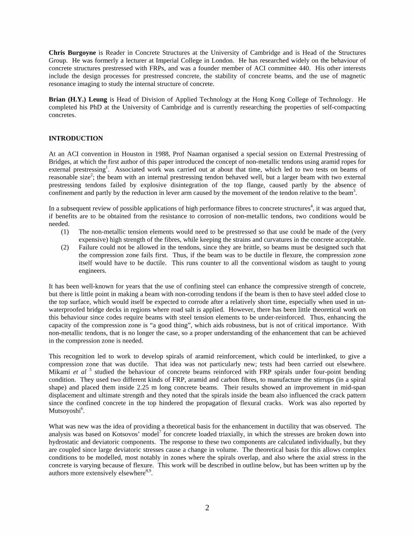
Chris Burgoyne is Reader in Concrete Structures at the University of Cambridge and is Head of the Structures Group. He was formerly a lecturer at Imperial College in London. He has researched widely on the behaviour of concrete structures prestressed with FRPs, and was a founder member of ACI committee 440. His other interests include the design processes for prestressed concrete, the stability of concrete beams, and the use of magnetic resonance imaging to study the internal structure of concrete. Brian (H.Y.) Leung is Head of Division of Applied Technology at the Hong Kong College of Technology. He completed his PhD at the University of Cambridge and is currently researching the properties of self-compacting concretes. INTRODUCTION At an ACI convention in Houston in 1988, Prof Naaman organised a special session on External Prestressing of Bridges, at which the first author of this paper introduced the concept of non-metallic tendons using aramid ropes for external prestressing1. Associated work was carried out at about that time, which led to two tests on beams of reasonable size2; the beam with an internal prestressing tendon behaved well, but a larger beam with two external prestressing tendons failed by explosive disintegration of the top flange, caused partly by the absence of confinement and partly by the reduction in lever arm caused by the movement of the tendon relative to the beam3. In a subsequent review of possible applications of high performance fibres to concrete structures4, it was argued that, if benefits are to be obtained from the resistance to corrosion of non-metallic tendons, two conditions would be needed.
(1) The non-metallic tension elements would need to be prestressed so that use could be made of the (very expensive) high strength of the fibres, while keeping the strains and curvatures in the concrete acceptable.
(2) Failure could not be allowed in the tendons, since they are brittle, so beams must be designed such that the compression zone fails first. Thus, if the beam was to be ductile in flexure, the compression zone itself would have to be ductile. This runs counter to all the conventional wisdom as taught to young engineers.
It has been well-known for years that the use of confining steel can enhance the compressive strength of concrete, but there is little point in making a beam with non-corroding tendons if the beam is then to have steel added close to the top surface, which would itself be expected to corrode after a relatively short time, especially when used in un-waterproofed bridge decks in regions where road salt is applied. However, there has been little theoretical work on this behaviour since codes require beams with steel tension elements to be under-reinforced. Thus, enhancing the capacity of the compression zone is “a good thing”, which aids robustness, but is not of critical importance. With non-metallic tendons, that is no longer the case, so a proper understanding of the enhancement that can be achieved in the compression zone is needed. This recognition led to work to develop spirals of aramid reinforcement, which could be interlinked, to give a compression zone that was ductile. That idea was not particularly new; tests had been carried out elsewhere. Mikami et al 5 studied the behaviour of concrete beams reinforced with FRP spirals under four-point bending condition. They used two different kinds of FRP, aramid and carbon fibres, to manufacture the stirrups (in a spiral shape) and placed them inside 2.25 m long concrete beams. Their results showed an improvement in mid-span displacement and ultimate strength and they noted that the spirals inside the beam also influenced the crack pattern since the confined concrete in the top hindered the propagation of flexural cracks. Work was also reported by Mutsoyoshi6. What was new was the idea of providing a theoretical basis for the enhancement in ductility that was observed. The analysis was based on Kotsovos’ model7 for concrete loaded triaxially, in which the stresses are broken down into hydrostatic and deviatoric components. The response to these two components are calculated individually, but they are coupled since large deviatoric stresses cause a change in volume. The theoretical basis for this allows complex conditions to be modelled, most notably in zones where the spirals overlap, and also where the axial stress in the concrete is varying because of flexure. This work will be described in outline below, but has been written up by the authors more extensively elsewhere8,9.
2
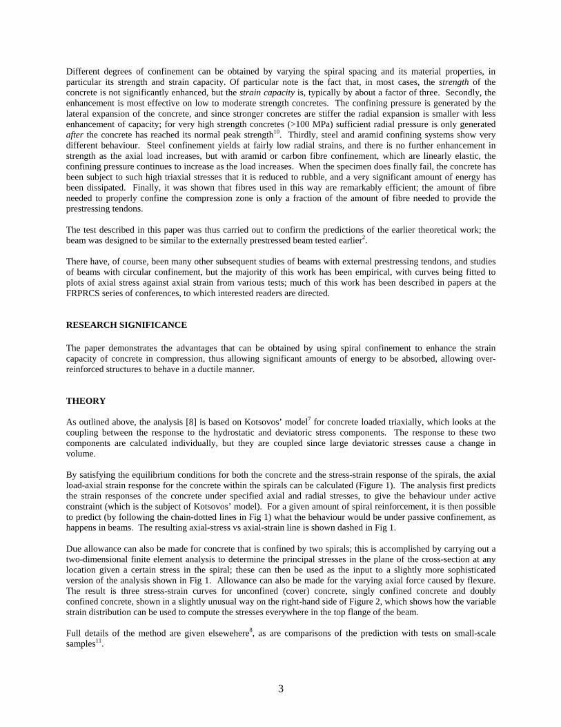
Different degrees of confinement can be obtained by varying the spiral spacing and its material properties, in particular its strength and strain capacity. Of particular note is the fact that, in most cases, the strength of the concrete is not significantly enhanced, but the strain capacity is, typically by about a factor of three. Secondly, the enhancement is most effective on low to moderate strength concretes. The confining pressure is generated by the lateral expansion of the concrete, and since stronger concretes are stiffer the radial expansion is smaller with less enhancement of capacity; for very high strength concretes (>100 MPa) sufficient radial pressure is only generated after the concrete has reached its normal peak strength10. Thirdly, steel and aramid confining systems show very different behaviour. Steel confinement yields at fairly low radial strains, and there is no further enhancement in strength as the axial load increases, but with aramid or carbon fibre confinement, which are linearly elastic, the confining pressure continues to increase as the load increases. When the specimen does finally fail, the concrete has been subject to such high triaxial stresses that it is reduced to rubble, and a very significant amount of energy has been dissipated. Finally, it was shown that fibres used in this way are remarkably efficient; the amount of fibre needed to properly confine the compression zone is only a fraction of the amount of fibre needed to provide the prestressing tendons. The test described in this paper was thus carried out to confirm the predictions of the earlier theoretical work; the beam was designed to be similar to the externally prestressed beam tested earlier2. There have, of course, been many other subsequent studies of beams with external prestressing tendons, and studies of beams with circular confinement, but the majority of this work has been empirical, with curves being fitted to plots of axial stress against axial strain from various tests; much of this work has been described in papers at the FRPRCS series of conferences, to which interested readers are directed. RESEARCH SIGNIFICANCE The paper demonstrates the advantages that can be obtained by using spiral confinement to enhance the strain capacity of concrete in compression, thus allowing significant amounts of energy to be absorbed, allowing over-reinforced structures to behave in a ductile manner. THEORY As outlined above, the analysis [8] is based on Kotsovos’ model7 for concrete loaded triaxially, which looks at the coupling between the response to the hydrostatic and deviatoric stress components. The response to these two components are calculated individually, but they are coupled since large deviatoric stresses cause a change in volume. By satisfying the equilibrium conditions for both the concrete and the stress-strain response of the spirals, the axial load-axial strain response for the concrete within the spirals can be calculated (Figure 1). The analysis first predicts the strain responses of the concrete under specified axial and radial stresses, to give the behaviour under active constraint (which is the subject of Kotsovos’ model). For a given amount of spiral reinforcement, it is then possible to predict (by following the chain-dotted lines in Fig 1) what the behaviour would be under passive confinement, as happens in beams. The resulting axial-stress vs axial-strain line is shown dashed in Fig 1. Due allowance can also be made for concrete that is confined by two spirals; this is accomplished by carrying out a two-dimensional finite element analysis to determine the principal stresses in the plane of the cross-section at any location given a certain stress in the spiral; these can then be used as the input to a slightly more sophisticated version of the analysis shown in Fig 1. Allowance can also be made for the varying axial force caused by flexure. The result is three stress-strain curves for unconfined (cover) concrete, singly confined concrete and doubly confined concrete, shown in a slightly unusual way on the right-hand side of Figure 2, which shows how the variable strain distribution can be used to compute the stresses everywhere in the top flange of the beam. Full details of the method are given elsewehere8, as are comparisons of the prediction with tests on small-scale samples11.
3
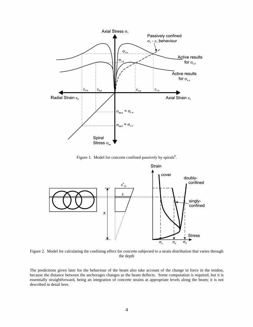
Figure 1. Model for concrete confined passively by spirals8.
Figure 2. Model for calculating the confining effect for concrete subjected to a strain distribution that varies through the depth
The predictions given later for the behaviour of the beam also take account of the change in force in the tendon, because the distance between the anchorages changes as the beam deflects. Some computation is required, but it is essentially straightforward, being an integration of concrete strains at appropriate levels along the beam; it is not described in detail here.
4

BEAM TEST In order to provide a comparison with theory at an appropriate scale, and to give a good comparison with the earlier test2, it was decided to fabricate as large a beam as could sensibly be accommodated in the laboratory, which restricted the overall length to about 8 m.. The beam was fully-prestressed, with two external tendons. The proportions and prestressing level were designed to be representative of normal concrete beams. The beam had a T-shape cross-section, with two parallel-lay aramid ropes as the prestressing tendons, each of which had a nominal breaking load of 60 tonnes. The cross-section was enlarged at the ends to provide space for the anchorages for the tendons, and provided with deflectors to vary the tendon eccentricity. The amount of confinement, which was kept constant through the full length of the beam, was chosen so that beam failure would be expected to occur by rupture of the spirals after significant deformation of the compression flange. The tendons were horizontal in the central 2 m of the beam and the deflected angle was 3.83o at both ends. Prestressing tendons Each prestressing tendon was formed from a Type G Parafil rope12 with a nominal breaking load of 60 tonnes, as manufactured by Linear Composites Ltd. Each rope contains a core of continuous Kevlar 49 aramid yarns, manufactured by Du Pont; the yarns are parallel and are contained within a thermoplastic sheath that both shields the fibres from ultra-violet light and gives some structure to the rope. Anchorage of the rope is provided by a barrel-and-spike termination system that can develop the full strength of the rope; the barrel is provided with two threads, an internal thread for a pull-rod to connect to the jack, and an external thread for a back-nut to provide the permanent anchor, and to allow some adjustment. Care has to be taken when cutting the rope to length to ensure that the tendon has the right length after prestressing13. The results of a tensile test on the rope, using the standard anchors are shown in Table 1; failure occurs in the body of the rope and not in the termination.
Table 1. Mechanical properties of Parafil rope
Material Core area Ultimate load Ultimate strain
Parafil rope 305.5 mm2 600 kN 1.77 %
Confining Spirals The compression confinement was formed from a layer of six interlocking spirals. Each spiral had a diameter of 100 mm and a pitch of 35 mm; the centre-to-centre distance between adjacent spirals was 62 mm. Each spiral was formed from a loosely twisted bundle of ten aramid yarns, impregnated with resin and then wrapped around a collapsible plastic mould from which they were removed once the resin had hardened. The mechanical properties of the bundle, as measured on straight samples manufactured in the same way, are listed in Table 2.
Table 2. Mechanical properties of aramid spirals
Material Cross-sectional area
Ultimate load
Ultimate stress
Ultimate strain
Elastic modulus
Kevlar 49 aramid
(ten yarns)
1.75 mm2
(excluding resin) 2.4 kN 1.38 GPa 1.53 % 90 GPa
5
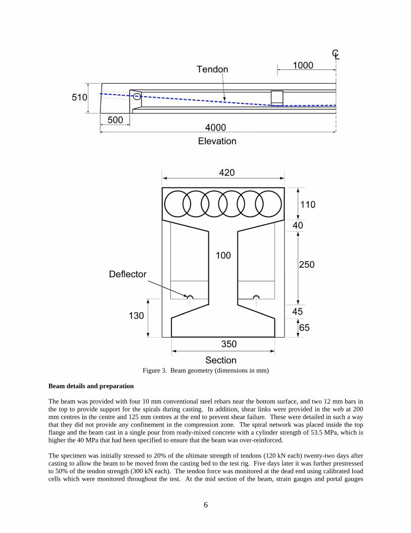
Figure 3. Beam geometry (dimensions in mm)
Beam details and preparation The beam was provided with four 10 mm conventional steel rebars near the bottom surface, and two 12 mm bars in the top to provide support for the spirals during casting. In addition, shear links were provided in the web at 200 mm centres in the centre and 125 mm centres at the end to prevent shear failure. These were detailed in such a way that they did not provide any confinement in the compression zone. The spiral network was placed inside the top flange and the beam cast in a single pour from ready-mixed concrete with a cylinder strength of 53.5 MPa, which is higher the 40 MPa that had been specified to ensure that the beam was over-reinforced. The specimen was initially stressed to 20% of the ultimate strength of tendons (120 kN each) twenty-two days after casting to allow the beam to be moved from the casting bed to the test rig. Five days later it was further prestressed to 50% of the tendon strength (300 kN each). The tendon force was monitored at the dead end using calibrated load cells which were monitored throughout the test. At the mid section of the beam, strain gauges and portal gauges
6

were installed at different heights. Four-point bending was applied by means of a 100 tonne hydraulic jack centrally mounted on a steel frame, with another load cell to monitor the applied load. A spreader beam was used to provide a constant bending moment region. The mid-span deflection was monitored using a long-travel (1.5 m) displacement transducer, and all data recorded by a data logger. Testing procedures The test programme was divided into two phases. During the first, three load cycles were applied. In each cycle the peak load was maintained for one minute before unloading. The peak load of the first load-cycle (100 kN) was lower than the cracking load, so no concrete cracking was expected. The second 150 kN load-cycle was slightly greater than the cracking load. For the third load-cycle, the peak load (200 kN) was further increased, and crack propagation should be noticeable. In the second phase, two further load-cycles (220 kN and 250 kN) were carried out together with the ultimate load test. RESULTS Failure pattern The crack pattern was marked at load levels of 100 kN, 150 kN and 200 kN. As expected, no cracks were observed at 100 kN. Small cracks were seen when the external load reached 150 kN, all of which propagated vertically from the bottom, but they were confined to the constant bending moment region, and remained in the bottom flange. At 200 kN a more extensive crack pattern was observed (Figure 4). The cracks increased in number and length. The cracking region extended outside the constant moment region, covering the central 4 m of the beam. The cracks outside the constant moment region were mostly inclined at an angle towards the loading points, while the cracks inside the constant bending moment region propagated upwards, as expected. Some horizontal cracking was observed in the top flange, as shown in Figure 5; by examining the depth of cracking, it was found that the cracked concrete was confined to the cover, outside the spirals as expected. With increased loading, the top cover concrete began to crush and to fall from the top flange while the flexural cracks in the bottom of the beam extended.
Figure 4. Prestressed concrete beam at 200 kN
7
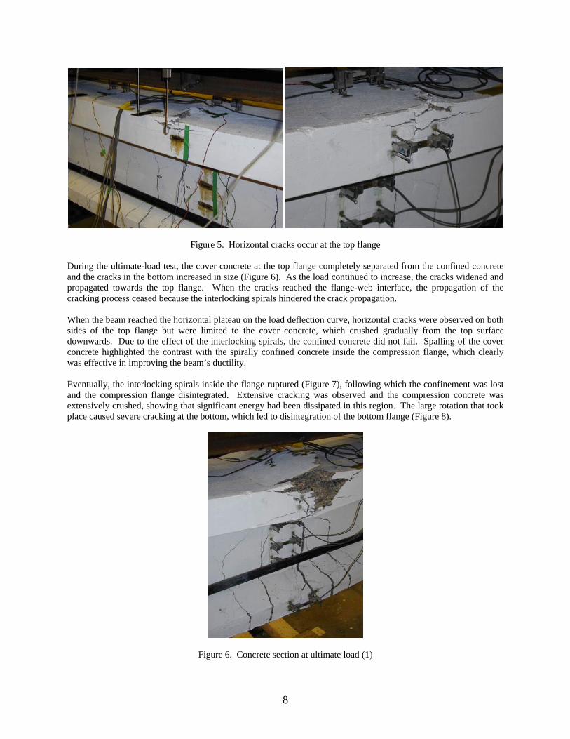
Figure 5. Horizontal cracks occur at the top flange During the ultimate-load test, the cover concrete at the top flange completely separated from the confined concrete and the cracks in the bottom increased in size (Figure 6). As the load continued to increase, the cracks widened and propagated towards the top flange. When the cracks reached the flange-web interface, the propagation of the cracking process ceased because the interlocking spirals hindered the crack propagation. When the beam reached the horizontal plateau on the load deflection curve, horizontal cracks were observed on both sides of the top flange but were limited to the cover concrete, which crushed gradually from the top surface downwards. Due to the effect of the interlocking spirals, the confined concrete did not fail. Spalling of the cover concrete highlighted the contrast with the spirally confined concrete inside the compression flange, which clearly was effective in improving the beam’s ductility. Eventually, the interlocking spirals inside the flange ruptured (Figure 7), following which the confinement was lost and the compression flange disintegrated. Extensive cracking was observed and the compression concrete was extensively crushed, showing that significant energy had been dissipated in this region. The large rotation that took place caused severe cracking at the bottom, which led to disintegration of the bottom flange (Figure 8).
Figure 6. Concrete section at ultimate load (1)
8
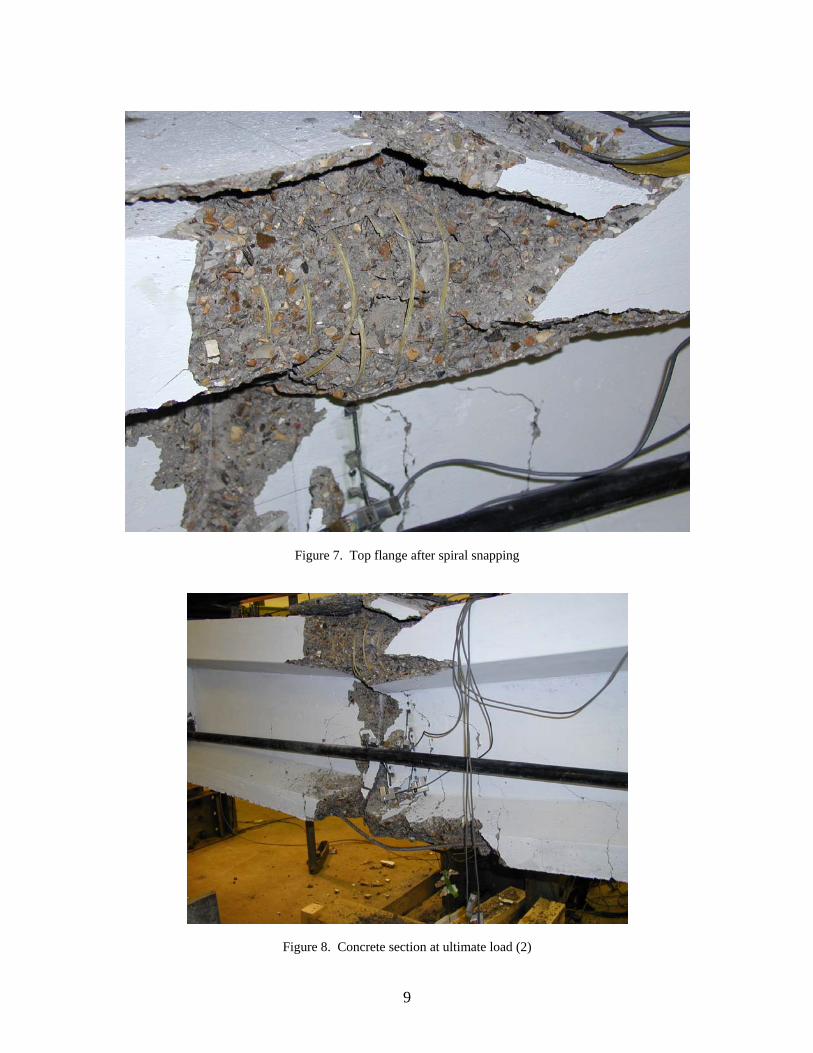
Figure 7. Top flange after spiral snapping
Figure 8. Concrete section at ultimate load (2)
9
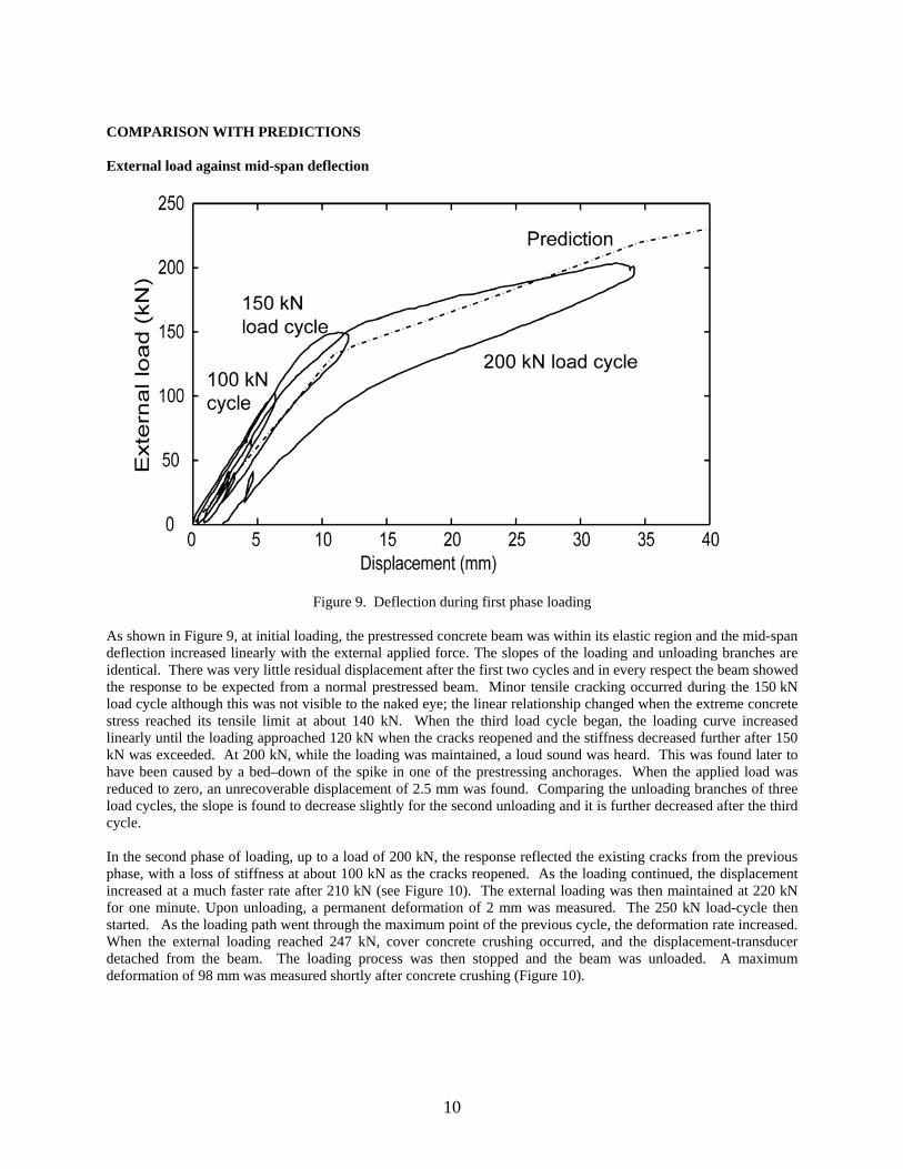
COMPARISON WITH PREDICTIONS External load against mid-span deflection
Figure 9. Deflection during first phase loading
As shown in Figure 9, at initial loading, the prestressed concrete beam was within its elastic region and the mid-span deflection increased linearly with the external applied force. The slopes of the loading and unloading branches are identical. There was very little residual displacement after the first two cycles and in every respect the beam showed the response to be expected from a normal prestressed beam. Minor tensile cracking occurred during the 150 kN load cycle although this was not visible to the naked eye; the linear relationship changed when the extreme concrete stress reached its tensile limit at about 140 kN. When the third load cycle began, the loading curve increased linearly until the loading approached 120 kN when the cracks reopened and the stiffness decreased further after 150 kN was exceeded. At 200 kN, while the loading was maintained, a loud sound was heard. This was found later to have been caused by a bed–down of the spike in one of the prestressing anchorages. When the applied load was reduced to zero, an unrecoverable displacement of 2.5 mm was found. Comparing the unloading branches of three load cycles, the slope is found to decrease slightly for the second unloading and it is further decreased after the third cycle. In the second phase of loading, up to a load of 200 kN, the response reflected the existing cracks from the previous phase, with a loss of stiffness at about 100 kN as the cracks reopened. As the loading continued, the displacement increased at a much faster rate after 210 kN (see Figure 10). The external loading was then maintained at 220 kN for one minute. Upon unloading, a permanent deformation of 2 mm was measured. The 250 kN load-cycle then started. As the loading path went through the maximum point of the previous cycle, the deformation rate increased. When the external loading reached 247 kN, cover concrete crushing occurred, and the displacement-transducer detached from the beam. The loading process was then stopped and the beam was unloaded. A maximum deformation of 98 mm was measured shortly after concrete crushing (Figure 10).
10

Figure 10. Deflection during second phase loading
Subsequently, the beam was reloaded to failure as shown in Figure 11. The slope of the response reduced once the load had exceeded 60 kN, and continued to decrease until a load of 225 kN was applied, by which time the displacement had reached 100 mm. The beam continued to withstand the same load until the deflection had reached 180 mm, after which the load started to drop slowly. The beam finally failed when one of the spirals snapped by which time the displacement was 198 mm.
Figure 11. Deflection during ultimate load test.
11
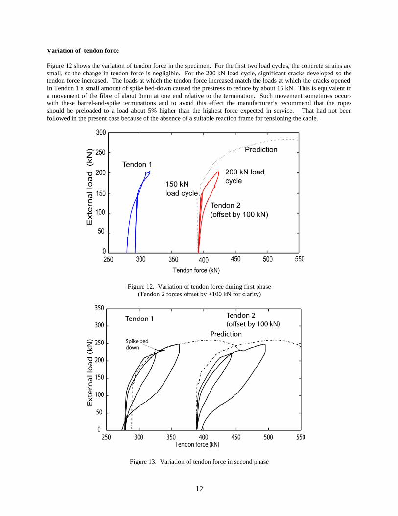
Variation of tendon force Figure 12 shows the variation of tendon force in the specimen. For the first two load cycles, the concrete strains are small, so the change in tendon force is negligible. For the 200 kN load cycle, significant cracks developed so the tendon force increased. The loads at which the tendon force increased match the loads at which the cracks opened. In Tendon 1 a small amount of spike bed-down caused the prestress to reduce by about 15 kN. This is equivalent to a movement of the fibre of about 3mm at one end relative to the termination. Such movement sometimes occurs with these barrel-and-spike terminations and to avoid this effect the manufacturer’s recommend that the ropes should be preloaded to a load about 5% higher than the highest force expected in service. That had not been followed in the present case because of the absence of a suitable reaction frame for tensioning the cable.
Figure 12. Variation of tendon force during first phase (Tendon 2 forces offset by +100 kN for clarity)
Figure 13. Variation of tendon force in second phase
12
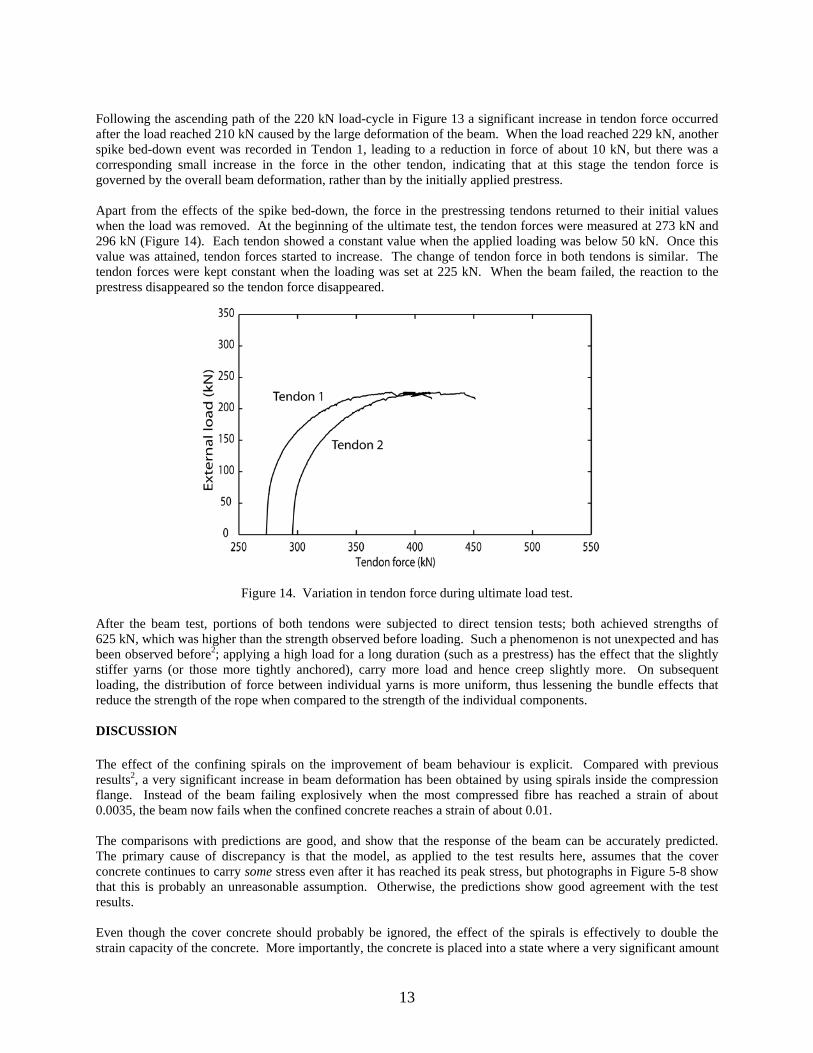
Following the ascending path of the 220 kN load-cycle in Figure 13 a significant increase in tendon force occurred after the load reached 210 kN caused by the large deformation of the beam. When the load reached 229 kN, another spike bed-down event was recorded in Tendon 1, leading to a reduction in force of about 10 kN, but there was a corresponding small increase in the force in the other tendon, indicating that at this stage the tendon force is governed by the overall beam deformation, rather than by the initially applied prestress. Apart from the effects of the spike bed-down, the force in the prestressing tendons returned to their initial values when the load was removed. At the beginning of the ultimate test, the tendon forces were measured at 273 kN and 296 kN (Figure 14). Each tendon showed a constant value when the applied loading was below 50 kN. Once this value was attained, tendon forces started to increase. The change of tendon force in both tendons is similar. The tendon forces were kept constant when the loading was set at 225 kN. When the beam failed, the reaction to the prestress disappeared so the tendon force disappeared.
Figure 14. Variation in tendon force during ultimate load test. After the beam test, portions of both tendons were subjected to direct tension tests; both achieved strengths of 625 kN, which was higher than the strength observed before loading. Such a phenomenon is not unexpected and has been observed before2; applying a high load for a long duration (such as a prestress) has the effect that the slightly stiffer yarns (or those more tightly anchored), carry more load and hence creep slightly more. On subsequent loading, the distribution of force between individual yarns is more uniform, thus lessening the bundle effects that reduce the strength of the rope when compared to the strength of the individual components. DISCUSSION The effect of the confining spirals on the improvement of beam behaviour is explicit. Compared with previous results2, a very significant increase in beam deformation has been obtained by using spirals inside the compression flange. Instead of the beam failing explosively when the most compressed fibre has reached a strain of about 0.0035, the beam now fails when the confined concrete reaches a strain of about 0.01. The comparisons with predictions are good, and show that the response of the beam can be accurately predicted. The primary cause of discrepancy is that the model, as applied to the test results here, assumes that the cover concrete continues to carry some stress even after it has reached its peak stress, but photographs in Figure 5-8 show that this is probably an unreasonable assumption. Otherwise, the predictions show good agreement with the test results. Even though the cover concrete should probably be ignored, the effect of the spirals is effectively to double the strain capacity of the concrete. More importantly, the concrete is placed into a state where a very significant amount
13
of energy is absorbed in the compression zone before final failure. Unlike the earlier test, which failed explosively, the failure mode in this test was completely benign. The tendon force changes only when the concrete starts to crack significantly; under working load conditions the stress would not change at all, which would mean fatigue in the termination would not be an issue and stress-rupture calculations could be based solely on the prestress level. The change in tendon force at the ultimate load level is only about 25% of the tendon breaking load, or about half of the applied prestress. Since this would represent an extreme and very short-term loading case, stress-rupture would not be an issue in these circumstances. The change from brittle to ductile behaviour has been achieved with only a very small amount of additional fibre. The total amount of fibre in the compression zone spirals represents only about 1/6th of the amount of fibre in the prestressing tendons. This is thus making very effective use of a costly element. It could have been made even more effective if the spirals had been increased in size almost to the thickness of the top flange, since there is no need to provide cover to the FRP, and if different sized spirals had been used in the corners of the section to reduce the amount of cover concrete that was present. CONCLUSIONS Comparison of the load-deflection performance of the tested beam with previous data shows a significant increase in beam deformation. It shows that the compression concrete can be made ductile, so the old dictum that “all concrete must be under-reinforced” need no longer apply. It also shows that the strain capacity of tendons made from materials like aramid and carbon can be exploited to the full, and also that the prestressing level of these tendons is likely to be governed by stress-rupture criteria under the prestress force rather than at any ultimate strength condition. The test further shows that the use of FRP to make confining spirals is a very economic use of the fibre, with only a small amount of fibre providing a very significant change to the beam behaviour. The use of interlocking spirals not only enhances the strength and ductility of the composite beam, it also optimises the use of the externally anchored fibre tendons. The force in the prestressing tendon increases as the beam deflects but it does not fail at the ultimate load if the beam is properly dimensioned. To avoid spike-bed-down events occurring when the section is subject to very large deformations, the preload applied to bed-in the spikes in the termination should be carried out at a load in excess of that expected when the beam is taken to failure. CONVERSION FACTORS Since this work was carried out in metric units, all values in the text are in SI units. The following conversion factors should be used:- 1 in = 25.4 mm 1 lb = 4.448 N 1000 psi = 6.895 MPa 1 short ton = 0.907 tonnes
14

15
REFERENCES 1. BURGOYNE C.J., Properties of polyaramid ropes and implications for their use as external prestressing
tendons, External Prestressing in Bridges, ed. A.E.Naaman and J.E.Breen, American Concrete Institute, SP-120, 107-124, Detroit, 1990.
2. BURGOYNE C. J., GUIMARAES G. B. and CHAMBERS J. J. Tests on beams prestressed with unbonded polyaramid tendons. Cambridge University Engineering Department Technical Report, 1991, CUED/D-Struct/TR.132.
3. BURGOYNE C.J., CAMPOS C.M.de O. and GUIMARAES G.B., Behaviour of Beams with External Tendons, Procs FIP Symposium on Post-tensioned Concrete Structures, 865-871, London, September 1996.
4. BURGOYNE C.J., Rational Use of Advanced Composites in Concrete, Proc Inst. Civil Engrs, Structures and Buildings, 146, 253-262, August 2001.
5. MIKAMI H., KATOH M., TAKEUCHI H. and TAMURA T. Flexural and Shear Behaviour of RC Beams Reinforced with Braided FRP rods in Spiral Shape. Transaction of the Japan Concrete Institute, 1989, Vol.11.
6. MUTSUYOSHI H. and MACHIDA A. Behaviour of Prestressed Concrete Beams Using FRP as External Cable. Fiber-Reinforced-Plastic Reinforcement for Concrete Structures, International Symposium, ACI, 1993, SP138-25.
7. KOTSOVOS M.D. and NEWMAN J.B. “Behavior of concrete under multiaxial stress.” ACI J., 74, 443-446, 1977.
8. LEUNG H.Y. and BURGOYNE C.J., The uniaxial stress-strain relationship of spirally-confined concrete, ACI Materials Journal, 102/6, 445-453, November 2005.
9. LEUNG H.Y., Aramid fibre spirals to confine concrete in compression, PhD Thesis, University of Cambridge, 2000.
10. CHRISTOFIDES, E., Studies in High Strength Concrete, 4th Year Undergraduate Project, University of Cambridge, 1998.
11. LEUNG H.Y. and BURGOYNE C.J., Compressive Behaviour of Concrete Confined by Aramid Fibre Spirals, Proceedings of the International Conference on Structural Engineering, Mechanics and Computation, SEMC 2001, Cape Town, South Africa, 2-4 April 2001, 1357-1364.
12. BURGOYNE C.J., Parafil ropes for prestressing applications. Chapter in Fibre reinforcing for concrete structures: Properties and Applications, ed. A. Nanni, 333-354, Elsevier, 1993.
13. BURGOYNE C. J. Laboratory testing on Parafil ropes. Symposium on Les materiaux nouveau pour la precontrainte et la renforcement d’ouvrages d’art, 1988, LCPC, Paris.