test report - s2einc.com and matrix/ce cert 2.pdf · report no. : eeszf02280001 page 3 of 53
TRANSCRIPT
Report No. : EESZF02280001 Page 1 of 53
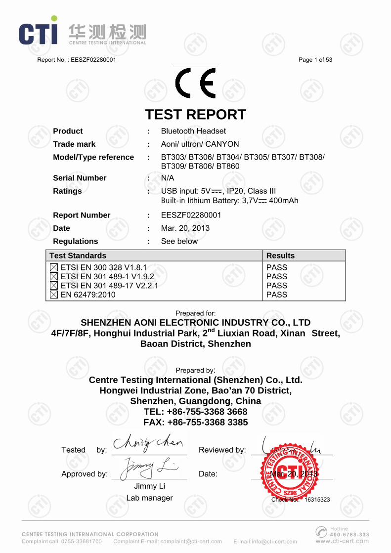
TEST REPORT
Product : Bluetooth Headset Trade mark : Aoni/ ultron/ CANYON Model/Type reference : BT303/ BT306/ BT304/ BT305/ BT307/ BT308/
BT309/ BT806/ BT860 Serial Number : N/A Ratings : USB input: 5V , IP20, Class III
Built-in lithium Battery: 3,7V 400mAh
Report Number : EESZF02280001 Date : Mar. 20, 2013 Regulations : See below
Test Standards Results ETSI EN 300 328 V1.8.1 ETSI EN 301 489-1 V1.9.2 ETSI EN 301 489-17 V2.2.1 EN 62479:2010
PASS PASS PASS PASS
Prepared for:
SHENZHEN AONI ELECTRONIC INDUSTRY CO., LTD 4F/7F/8F, Honghui Industrial Park, 2nd Liuxian Road, Xinan Street,
Baoan District, Shenzhen
Prepared by:
Centre Testing International (Shenzhen) Co., Ltd. Hongwei Industrial Zone, Bao’an 70 District,
Shenzhen, Guangdong, China TEL: +86-755-3368 3668 FAX: +86-755-3368 3385
Tested by: Reviewed by:
Approved by: Date: Mar. 20, 2013 Jimmy Li
Lab manager
Check No.: 16315323
Report No. : EESZF02280001 Page 2 of 53
TABLE OF CONTENTS 1. GENERAL INFORMATION .........................................................................................3
3. PRODUCT INFORMATION.........................................................................................5
4. TEST METHODOLOGY ..............................................................................................5
4.1 Test facilities .................................................................................................5 4.2 Test standards...............................................................................................5 4.3 List of test and measurement instruments.................................................5 4.4 Uncertainty of measurement........................................................................7
5. TEST SETUP AND OPERATION MODES..................................................................7
5.1 Principle of configuration selection ............................................................7 5.2 Special accessories and auxiliary equipment ............................................7
6. TRANSMITTER REQUIREMENT & TEST SUITES ....................................................8
6.1 RF output power............................................................................................8 6.2 Dwell time, Minimum Frequency Occupation and Hopping Sequence ..11 6.3 Hopping Frequency Separation .................................................................18 6.4 Adaptivity (Adaptive Frequency Hopping)................................................21 6.5 Occupied Channel Bandwidth ...................................................................27 6.6 Transmitter unwanted emissions in the out-of-band domain .................30 6.7 Transmitter unwanted emissions in the spurious domain......................34
7. RECEIVER REQUIREMENT & TEST SUITES .........................................................36
7.1 Receiver spurious emissions.....................................................................36
8. EMC REQUIREMENT & TEST SUITES....................................................................38
8.1 Immunity test results ..................................................................................38 8.1.1 RF electromagnetic field (RS) ......................................................40 8.1.2 Electrostatic discharge (ESD) ......................................................42
APPENDIX 1 PHOTOGRAPHS OF TEST SETUP .......................................................44
APPENDIX 2 PHOTOGRAPHS OF EUT ......................................................................45
(Note: N/A means not applicable)

Report No. : EESZF02280001 Page 3 of 53
1. GENERAL INFORMATION
2. TEST SUMMARY The complete list of measurements is given below:
Subclause Parameter to be measured Results Remark ETSI EN 300 328V1.8.1
4.3.1.1 RF output power Pass See clause 6.1 in this report
4.3.1.2 Duty Cycle, Tx-sequence, Tx-gap N/A
These requirements apply to non-adaptive frequency hopping equipment or to adaptive frequency hopping equipment operating in a non-adaptive mode.
4.3.1.3 Dwell time, Minimum Frequency Occupation and Hopping Sequence Pass See clause 6.2 in this report
4.3.1.4 Hopping Frequency Separation Pass See clause 6.3 in this report
4.3.1.5 Medium Utilisation (MU) factor N/A This requirement does not apply to adaptive equipment unless operating in a non-adaptive mode.
Applicant: SHENZHEN AONI ELECTRONIC INDUSTRY CO., LTD 4F/7F/8F, Honghui Industrial Park, 2nd Liuxian Road, Xinan Street, Baoan District, Shenzhen
Manufacturer: SHENZHEN AONI ELECTRONIC INDUSTRY CO., LTD 4F/7F/8F, Honghui Industrial Park, 2nd Liuxian Road, Xinan Street, Baoan District, Shenzhen
Factory: SHENZHEN AONI ELECTRONIC INDUSTRY CO., LTD 4F/7F/8F, Honghui Industrial Park, 2nd Liuxian Road, Xinan Street, Baoan District, Shenzhen
R&TTE Directive: 1999/5/EC
Product: Bluetooth Headset
Model/Type reference : BT303/ BT306/ BT304/ BT305/ BT307/ BT308/ BT309/ BT806/ BT860
Model/Type difference: All the models are identical except appearance, type and color.
Trade Name: Aoni/ ultron/ CANYON
Serial Number: N/A
Report Number: EESZF02280001
Sample Received Date: Mar. 12, 2013
Sample tested Date: Mar. 12, 2013 to Mar. 18, 2013

Report No. : EESZF02280001 Page 4 of 53
4.3.1.6 Adaptivity (Adaptive Frequency Hopping) Pass See clause 6.4 in this report
4.3.1.7 Occupied Channel Bandwidth Pass See clause 6.5 in this report
4.3.1.8 Transmitter unwanted emissions in the out-of-band domain Pass See clause 6.6 in this report
4.3.1.9 Transmitter unwanted emissions in the spurious domain Pass See clause 6.7 in this report
4.3.1.10 Receiver spurious emissions Pass See clause 7.1 in this report
4.2.1.11 Receiver Blocking N/A The device is adaptive equipment, but the RF output power is less than 10 dBm e.i.r.p.
Subclause Parameter to be measured Results Remark
ETSI EN 301 489-1V1.9.2
8.2 Radiated emission (RE) N/A This test is only applicable to ancillary equipment, and the EUT has no any ancillary device.
8.4 Conducted emission (CE) 8.5 Harmonic current emissions
8.6 Voltage fluctuations and flicker
N/A The power supply of device is by DC battery.
9.2 RF electromagnetic field (80MHz to 1GHz and 1.4GHz to 2.7GHz) (RS) Pass See clause 8.1.1 in this report
9.3 Electrostatic discharge (ESD) Pass See clause 8.1.2 in this report
9.4 Fast transients common mode (EFT)
9.5 RF common mode 0.15MHz to 80MHz (CS)
N/A The power supply of device is by DC battery.
9.6 Transients and surges N/A The EUT is not for vehicle use. 9.7 Voltage dips and interruptions
9.8 Surges, line to line and line to ground
N/A The power supply of device is by DC battery.
EN 62479:2010
--- Electromagnetic filed for human exposure Pass
From the test results, the max power is -3.94dBm, so it complies with the requirements of EN 62479:2010 in accordance with the clause 4.2 and Table A.1.

Report No. : EESZF02280001 Page 5 of 53
3. PRODUCT INFORMATION Items Description
Rating USB input: 5V , IP20, Class III Built-in lithium Battery: 3,7V 400mAh
Intentional Transceiver Intentional Transceiver
Modulation Frequency Hopping Spread Spectrum (FHSS) 1. GFSK 2.π/4-DQPSK 3. 8DPSK
Data Rate (Mbps) GFSK: 1 ; π/4-DQPSK: 2 ; 8DPSK: 3
Frequency Range 2402 ~ 2480 MHz
Channel Number 79 (at intervals of 1MHz)
Type PCB Antenna
Gain 1.2dBi The device is adaptive equipment without the possibility to switch to a non-adaptive mode. Model BT304 was selected for full test.
4. TEST METHODOLOGY 4.1 Test facilities Centre Testing International (Shenzhen) Co., Ltd. Hongwei Industrial Zone, Bao’an 70 District, Shenzhen, Guangdong, China 4.2 Test standards ETSI EN 300 328 V1.8.1 Electromagnetic compatibility and Radio spectrum Matters (ERM); Wideband transmission systems; Data transmission equipment operating in the 2,4 GHz ISM band and using wide band modulation techniques; Harmonized EN covering the essential requirements of article 3.2 of the R&TTE Directive ETSI EN 301 489-1 V1.9.2 Electromagnetic compatibility and Radio spectrum Matters (ERM); ElectroMagnetic Compatibility (EMC) standard for radio equipment and services; Part 1: Common technical requirements ETSI EN 301 489-17 V2.2.1 Electromagnetic compatibility and Radio spectrum Matters (ERM); ElectroMagnetic Compatibility (EMC) standard for radio equipment; Part 17: Specific conditions for Broadband Data Transmission Systems EN 62479:2010 Assesment of the compliance of low-power electronic and electrical equipment with the basic restrictions related to human exposure to electromagnetic fields (10 MHz to 300 GHz)
4.3 List of test and measurement instruments The measuring equipment utilized to perform the tests documented in this report has been calibrated once a year or in accordance with the manufacturer's recommendations, and is traceable under the ISO/IEC/EN 17025 to international or national standards. Equipment has been calibrated by accredited calibration laboratories
Report No. : EESZF02280001 Page 6 of 53
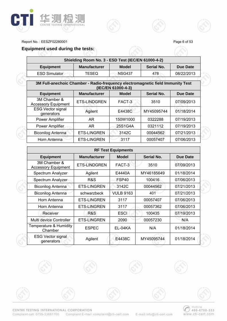
Equipment used during the tests:
Shielding Room No. 3 - ESD Test (IEC/EN 61000-4-2) Equipment Manufacturer Model Serial No. Due Date
ESD Simulator TESEQ NSG437 478 08/22/2013
3M Full-anechoic Chamber - Radio-frequency electromagnetic field Immunity Test (IEC/EN 61000-4-3)
Equipment Manufacturer Model Serial No. Due Date 3M Chamber &
Accessory Equipment ETS-LINDGREN FACT-3 3510 07/09/2013
ESG Vector signal generators Agilent E4438C MY45095744 01/18/2014
Power Amplifier AR 150W1000 0322288 07/19/2013
Power Amplifier AR 25S1G4A 0321112 07/19/2013
Biconilog Antenna ETS-LINGREN 3142C 00044562 07/21/2013
Horn Antenna ETS-LINGREN 3117 00057407 07/06/2013
RF Test Equipments Equipment Manufacturer Model Serial No. Due Date
3M Chamber & Accessory Equipment ETS-LINDGREN FACT-3 3510 07/09/2013
Spectrum Analyzer Agilent E4440A MY46185649 01/18/2014
Spectrum Analyzer R&S FSP40 100416 07/06/2013
Biconilog Antenna ETS-LINGREN 3142C 00044562 07/21/2013
Biconilog Antenna schwarzbeck VULB 9163 401 07/21/2013
Horn Antenna ETS-LINGREN 3117 00057407 07/06/2013
Horn Antenna ETS-LINGREN 3117 00057362 07/06/2013
Receiver R&S ESCI 100435 07/19/2013
Multi device Controller ETS-LINGREN 2090 00057230 N/A Temperature & Humidity
Chamber ESPEC EL-04KA N/A 01/18/2014
ESG Vector signal generators Agilent E4438C MY45095744 01/18/2014
Report No. : EESZF02280001 Page 7 of 53
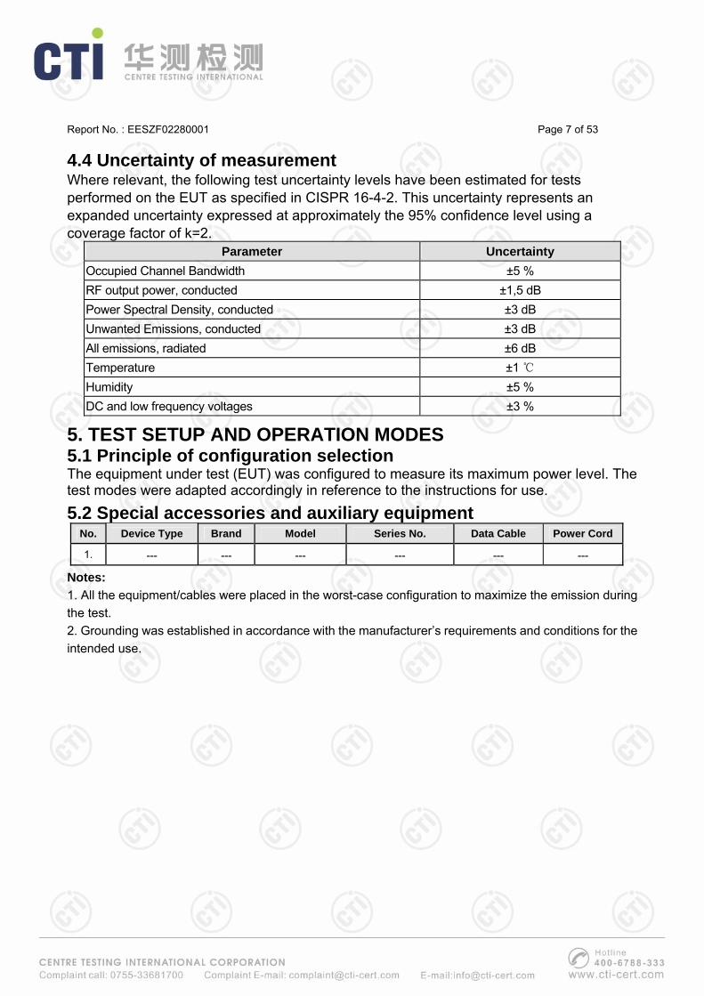
4.4 Uncertainty of measurement Where relevant, the following test uncertainty levels have been estimated for tests performed on the EUT as specified in CISPR 16-4-2. This uncertainty represents an expanded uncertainty expressed at approximately the 95% confidence level using a coverage factor of k=2.
Parameter Uncertainty Occupied Channel Bandwidth ±5 % RF output power, conducted ±1,5 dB Power Spectral Density, conducted ±3 dB Unwanted Emissions, conducted ±3 dB All emissions, radiated ±6 dB Temperature ±1 ℃ Humidity ±5 % DC and low frequency voltages ±3 %
5. TEST SETUP AND OPERATION MODES 5.1 Principle of configuration selection The equipment under test (EUT) was configured to measure its maximum power level. The test modes were adapted accordingly in reference to the instructions for use.
5.2 Special accessories and auxiliary equipment No. Device Type Brand Model Series No. Data Cable Power Cord
1. --- --- --- --- --- ---
Notes: 1. All the equipment/cables were placed in the worst-case configuration to maximize the emission during the test. 2. Grounding was established in accordance with the manufacturer’s requirements and conditions for the intended use.
Report No. : EESZF02280001 Page 8 of 53
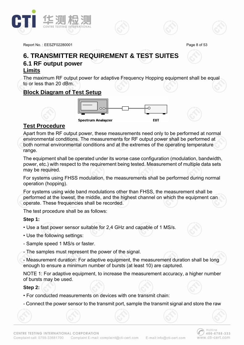
6. TRANSMITTER REQUIREMENT & TEST SUITES 6.1 RF output power Limits The maximum RF output power for adaptive Frequency Hopping equipment shall be equal to or less than 20 dBm.
Block Diagram of Test Setup
Test Procedure Apart from the RF output power, these measurements need only to be performed at normal environmental conditions. The measurements for RF output power shall be performed at both normal environmental conditions and at the extremes of the operating temperature range. The equipment shall be operated under its worse case configuration (modulation, bandwidth, power, etc.) with respect to the requirement being tested. Measurement of multiple data sets may be required. For systems using FHSS modulation, the measurements shall be performed during normal operation (hopping). For systems using wide band modulations other than FHSS, the measurement shall be performed at the lowest, the middle, and the highest channel on which the equipment can operate. These frequencies shall be recorded. The test procedure shall be as follows: Step 1: • Use a fast power sensor suitable for 2,4 GHz and capable of 1 MS/s. • Use the following settings: - Sample speed 1 MS/s or faster. - The samples must represent the power of the signal. - Measurement duration: For adaptive equipment, the measurement duration shall be long enough to ensure a minimum number of bursts (at least 10) are captured. NOTE 1: For adaptive equipment, to increase the measurement accuracy, a higher number of bursts may be used. Step 2: • For conducted measurements on devices with one transmit chain: - Connect the power sensor to the transmit port, sample the transmit signal and store the raw
Report No. : EESZF02280001 Page 9 of 53
data. Use these stored samples in all following steps. • For conducted measurements on devices with multiple transmit chains: - Connect one power sensor to each transmit port for a synchronous measurement on all transmit ports. - Trigger the power sensors so that they start sampling at the same time. Make sure the time difference between the samples of all sensors is less than half the time between two samples. - For each instant in time, sum the power of the individual samples of all ports and store them. Use these stored samples in all following steps. Step 3: • Find the start and stop times of each burst in the stored measurement samples. NOTE 2: The start and stop times are defined as the points where the power is at least 20 dB below the RMS burst power calculated in step 4. Step 4: • Between the start and stop times of each individual burst calculate the RMS power over the burst. Save these Pburst values, as well as the start and stop times for each burst. Step 5: • The highest of all Pburst values (value "A" in dBm) will be used for maximum e.i.r.p. calculations. Step 6: • Add the (stated) antenna assembly gain "G" in dBi of the individual antenna. • If more than one antenna assembly is intended for this power setting, the maximum overall antenna gain G shall be used. • The RF Output Power (P) shall be calculated using the formula below:
P = A + G Step 7: The measurement shall be repeated at the lowest, the middle, and the highest frequency of the stated frequency range. These frequencies shall be recorded. FHSS equipment shall be made to hop continuously to each of these three frequencies separately. These measurements shall be performed at normal and extreme test conditions.

Report No. : EESZF02280001 Page 10 of 53
Test Results Worst case-- Modulation Type: GFSK Data Rate: 1Mbps
Equivalent isotropic radiated power 2402MHz 2441MHz 2480MHz Temperature
(℃) Voltage (V) dBm dBm dBm
Limit
Tnor = 25 3.7 -3.96 -12.50 -13.09
3.7 -3.94 -10.32 -12.36 Tmin = -20
3.3 -5.21 -9.36 -13.02
3.7 -4.63 -11.20 -10.93 Tmax = 55
3.3 -5.02 -12.02 -9.89
20dBm
Note: 1. The power supply of EUT is by battery, and extreme test voltage shall be 0.9 time (nickel-cadmium alkaline battery) the nominal voltage of the battery. 2. The operated temperature is -20°C to +55°C.

Report No. : EESZF02280001 Page 11 of 53
6.2 Dwell time, Minimum Frequency Occupation and Hopping Sequence Limits Adaptive Frequency Hopping systems shall be capable of operating over a minimum of 70 % of the 2400 to 2483.5MHz band. The maximum accumulated dwell time on any hopping frequency shall be 400 ms within any period of 400 ms multiplied by the minimum number of hopping frequencies (N) that have to be used. The hopping sequence(s) shall contain at least N hopping frequencies at all times, where N is 15 or 15 divided by the minimum Hopping Frequency Separation in MHz, whichever is the greater. The Minimum Frequency Occupation Time shall be equal to one dwell time within a period not exceeding four times the product of the dwell time per hop and the number of hopping frequencies in use.
Block Diagram of Test Setup
Test Procedure These measurements shall only be performed at normal test conditions. The equipment shall be configured to operate at its maximum Dwell Time and maximum Duty Cycle. The measurement shall be performed on a minimum of 2 hopping frequencies chosen arbitrary from the actual hopping sequence. The results as well as the frequencies on which the test was performed shall be recorded in the test report. The test procedure shall be as follows: Step 1: • The output of the transmitter shall be connected to a spectrum analyzer or equivalent. • The analyzer shall be set as follows: - Centre Frequency: Equal to the hopping frequency being investigated - Frequency Span: 0 Hz - RBW: ~ 50 % of the Occupied Channel Bandwidth - VBW: ≥ RBW - Detector Mode: RMS - Sweep time: Equal to the Dwell Time × Minimum number of hopping frequencies (N)

Report No. : EESZF02280001 Page 12 of 53
- Number of sweep points: 30 000 - Trace mode: Clear / Write - Trigger: Free Run Step 2: • Save the trace data to a file for further analysis by a computing device using an appropriate software application or program. Step 3: • Indentify the data points related to the frequency being investigated by applying a threshold. The data points resulting from transmissions on the hopping frequency being investigated are assumed to have much higher levels compared to data points resulting from transmissions on adjacent hopping frequencies. If a clear determination between these transmissions is not possible, the RBW in step 1 shall be further reduced. In addition, a channel filter may be used. • Count the number of data points identified as resulting from transmissions on the frequency being investigated and multiply this number by the time difference between two consecutive data points. Step 4: • The result in step 3 is the accumulated Dwell Time which shall comply with the limit provided in clauses 4.3.1.3.2.1 or 4.3.1.3.2.2 and which shall be recorded in the test report. Step 5: • Make the following changes on the analyzer and repeat steps 2 and 3.
Sweep time: 4 × Dwell Time × Actual number of hopping frequencies in use The hopping frequencies occupied by the system without having transmissions during the dwell time (blacklisted frequencies) should be taken into account in the actual number of hopping frequencies in use. If this number can not be determined (number of blacklisted frequencies unknown) it shall be assumed that the equipment uses the minimum number of hopping frequencies as defined in clauses 4.3.1.4.2.1 or 4.3.1.4.2.2. • The result shall be compared to the limit for the Minimum Frequency Occupation Time defined in clauses 4.3.1.3.2.1 or 4.3.1.3.2.2. This value shall be recorded in the test report. Step 6: • Make the following changes on the analyzer: - Start Frequency: 2 400 MHz - Stop Frequency: 2 483,5 MHz - RBW: ~ 50 % of the Occupied Channel Bandwidth (single hop) - VBW: ≥ RBW
Report No. : EESZF02280001 Page 13 of 53
- Detector Mode: RMS - Sweep time: Auto - Trace Mode: Max Hold - Trigger: Free Run • When the trace has completed, indentify the number of hopping frequencies used by the hopping sequence. • The result shall be compared to the limit (value N) defined in clauses 4.3.1.3.2.1 or 4.3.1.3.2.2. This value shall be recorded in the test report. For equipment with blacklisted frequencies, it might not be possible to verify the number of hopping frequencies in use. However they shall comply with the requirement for accumulated Dwell time and Minimum Frequency Occupation Time assuming the minimum number of hopping frequencies defined in clauses 4.3.1.3.2.1 or 4.3.1.3.2.2 are in use. Step 7: • For adaptive systems, using the lowest and highest -20 dB points from the total spectrum envelope obtained in step 6, it shall be verified whether the system uses 70 % of the band specified in clause 1. The result shall be recorded in the test report.
Test Results Worst case-- Modulation Type: GFSK Data Rate: 1Mbps
Maximum accumulated dwell time Frequency (MHz) Packet
Time Slot Length (ms) Dwell Time (ms) Limit (ms) 2402 DH5 2.9 309.3
2441 DH5 2.9 309.3
2480 DH5 2.9 309.3
≤400
Test Period: Dwell Time X Minimum number of hopping frequencies (N) Accumulated Dwell Time = Time Slot Length X Number of data points within a test period
Minimum accumulated dwell time Frequency
(MHz) Packet Time Slot Length (ms) Dwell Time (ms) Limit (ms)
2402 DH1 0.4 512
2441 DH1 0.4 512
2480 DH1 0.39 499.2
≥400
Test Period: 4 X Dwell Time X Minimum number of hopping frequencies (N) Accumulated Dwell Time = Time Slot Length X Number of data points within a test period

Report No. : EESZF02280001 Page 14 of 53
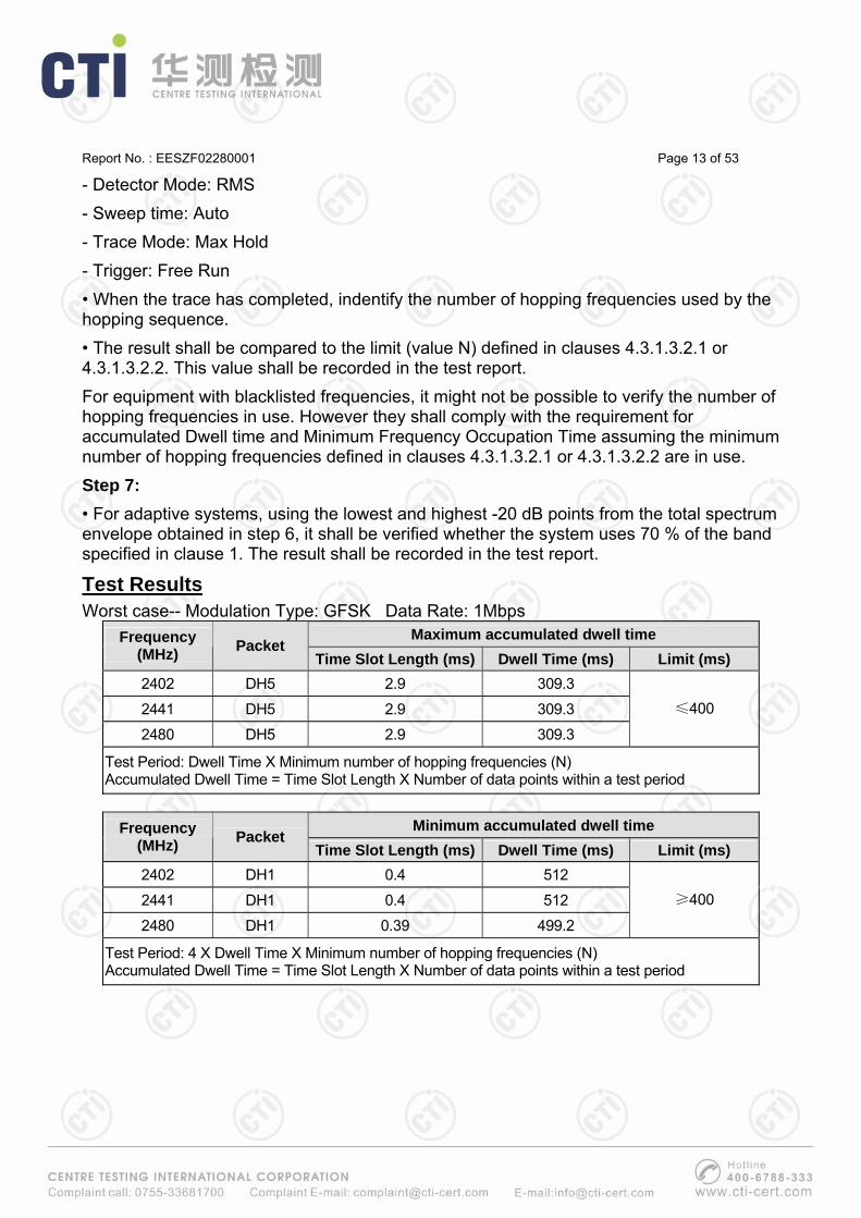
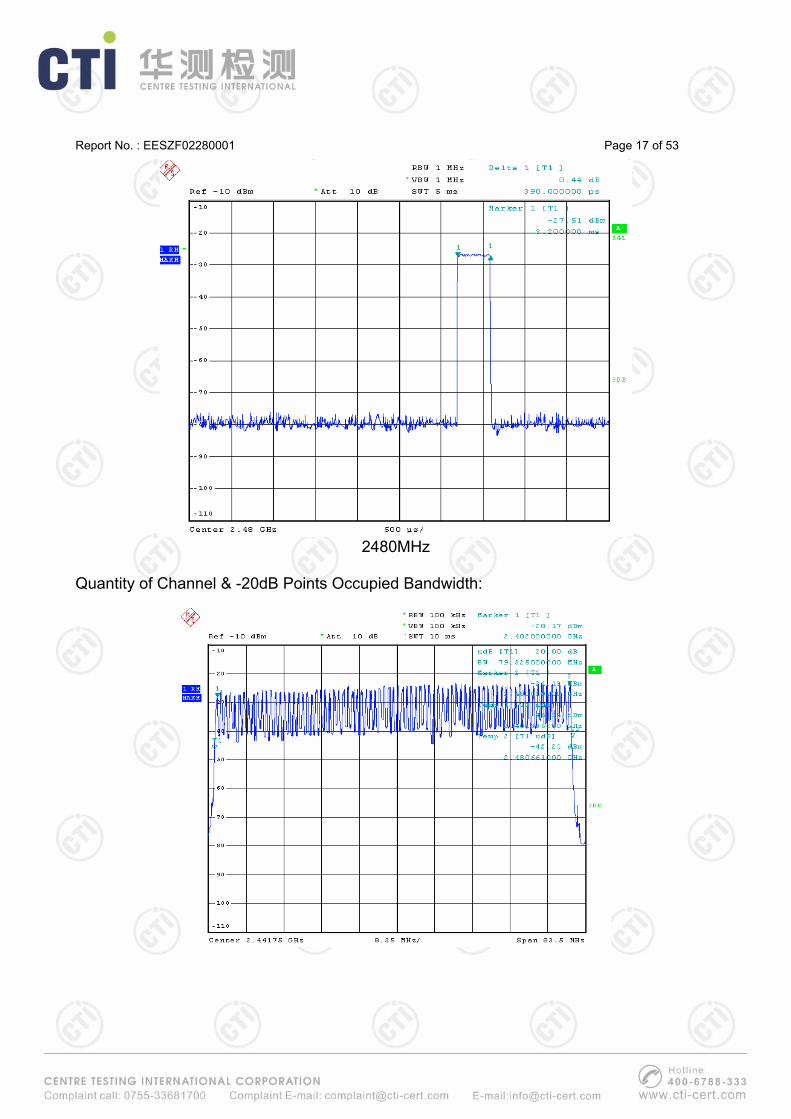
Frequency Band Number of Hopping Frequencies (N) Limit Result
79 15 Pass -20dB Points Occupied Bandwidth Limit Result2400-2483.5MHz
79.325MHz 83.5MHz X 70% = 58.45MHz Pass
Please refer to the test plots as below: DH5:
2402MHz

Report No. : EESZF02280001 Page 15 of 53
2441MHz
2480MHz

Report No. : EESZF02280001 Page 16 of 53
DH1:
2402MHz
2441MHz
Report No. : EESZF02280001 Page 17 of 53
2480MHz
Quantity of Channel & -20dB Points Occupied Bandwidth:

Report No. : EESZF02280001 Page 18 of 53
6.3 Hopping Frequency Separation Limits The minimum Hopping Frequency Separation shall be 100 kHz.
Block Diagram of Test Setup
Test Procedure These measurements shall only be performed at normal test conditions. The measurement shall be performed on 2 adjacent hopping frequencies. The frequencies on which the test was performed shall be recorded. The test procedure shall be as follows: Step 1: • The output of the transmitter shall be connected to a spectrum analyzer or equivalent. • The analyzer shall be set as follows: - Centre Frequency: Centre of the two adjacent hopping frequencies - Frequency Span: Sufficient to see the complete power envelope of both hopping frequencies - RBW: 1 % of the Span - VBW: 3 × RBW - Detector Mode: RMS - Trace Mode: Max Hold - Sweep Time: Auto Step 2: • Allow the trace to stabilize. • Use the marker-delta function to determine the Hopping Frequency Separation between the peaks of the two adjacent hopping frequencies. This value shall be compared with the limits defined in clause 4.3.1.4.2 and shall be recorded in the test report.
Report No. : EESZF02280001 Page 19 of 53
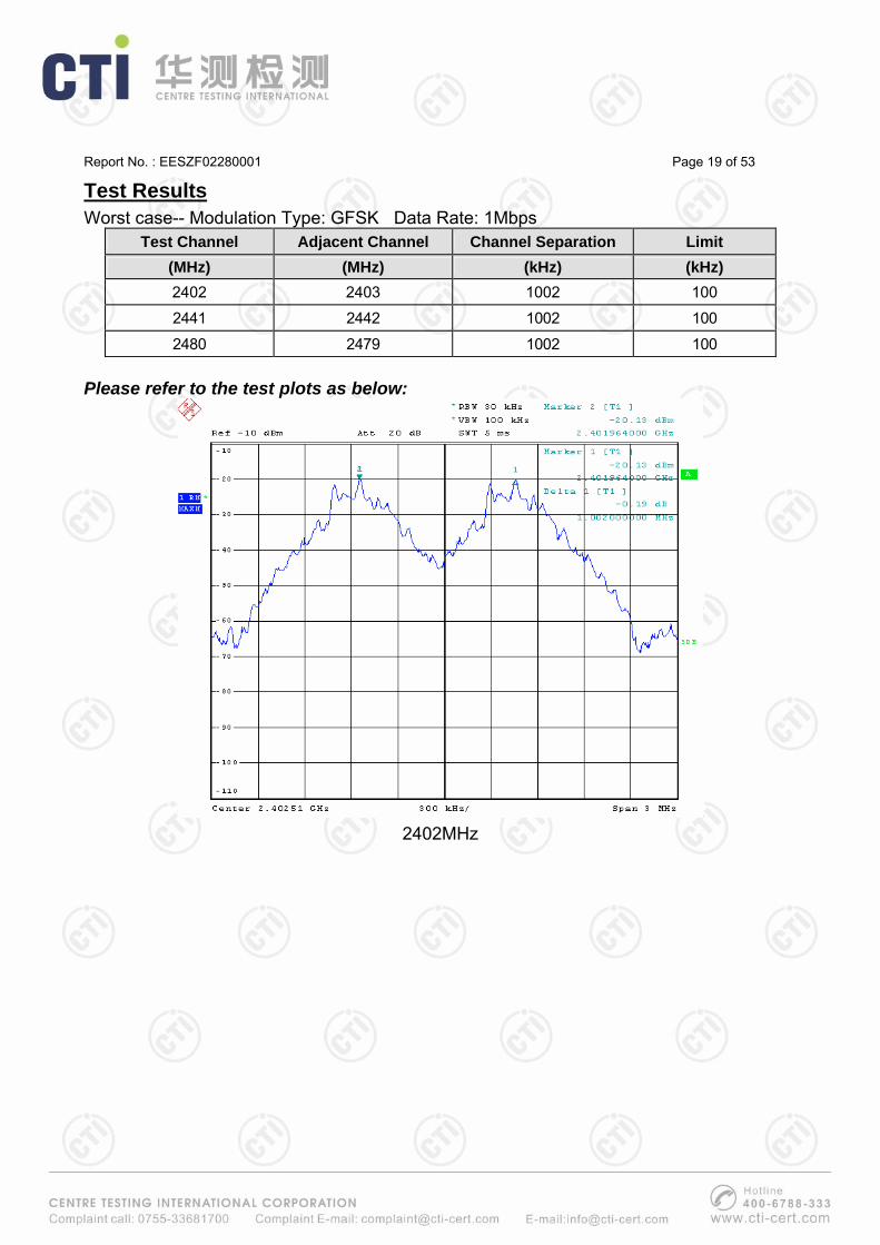
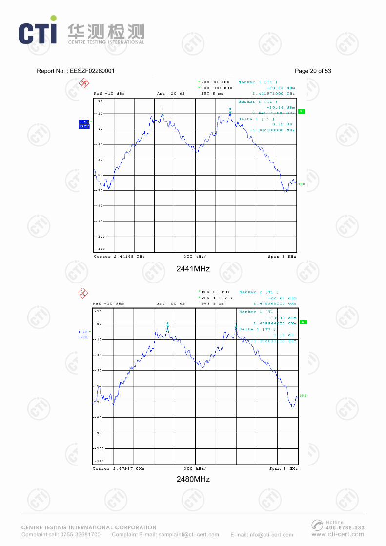
Test Results Worst case-- Modulation Type: GFSK Data Rate: 1Mbps
Test Channel Adjacent Channel Channel Separation Limit (MHz) (MHz) (kHz) (kHz) 2402 2403 1002 100
2441 2442 1002 100
2480 2479 1002 100 Please refer to the test plots as below:
2402MHz
Report No. : EESZF02280001 Page 20 of 53
2441MHz
2480MHz

Report No. : EESZF02280001 Page 21 of 53
6.4 Adaptivity (Adaptive Frequency Hopping) Limits Adaptive Frequency Hopping using other forms of DAA (non-LBT based) Adaptive Frequency Hopping equipment using non-LBT based DAA, shall comply with the following minimum set of requirements: 1) During normal operation, the equipment shall evaluate the presence of a signal for each of its hopping frequencies. If it is determined that a signal is present with a level above the detection threshold defined in step 5. the hopping frequency shall be marked as 'unavailable'. 2) The frequency shall remain unavailable for a minimum time equal to 1 second or 5 times the actual number of hopping frequencies multiplied with the Channel Occupancy Time whichever is the longest. There shall be no transmissions during this period on this frequency. After this, the hopping frequency may be considered again as an 'available' frequency. 3) The total time during which an equipment has transmissions on a given hopping frequency without re-evaluating the availability of that frequency is defined as the Channel Occupancy Time. The Channel Occupancy Time for a given hopping frequency shall be less than 40 ms. For equipment using a dwell time > 40 ms that want to have other transmissions during the same hop (dwell time) an Idle Period (no transmissions) of minimum 5 % of the Channel Occupancy Period with a minimum of 100 μs shall be implemented. After this, the procedure as in step 1 need to be repeated before having new transmissions on this hopping frequency during the same dwell time. NOTE: For non-LBT based frequency hopping systems with a dwell time < 40 ms, the maximum Channel Occupancy Time may be non-contiguous, i.e. spread over a number of hopping sequences (equal to 40 msec divided by the dwell time [msec]). 4) 'Unavailable' channels may be removed from or may remain in the hopping sequence, but in any case: - there shall be no transmissions on 'unavailable' channels; - a minimum of 15 hopping frequencies shall always be maintained. 5) The detection threshold shall be proportional to the transmit power of the transmitter: for a 20 dBm e.i.r.p. transmitter the detection threshold level (TL) shall be equal or lower than -70 dBm/MHz at the input to the receiver (assuming a 0 dBi receive antenna). For power levels below 20 dBm e.i.r.p., the detection threshold level may be relaxed to TL = -70 dBm/MHz + 20 - Pout e.i.r.p. (Pout in dBm). Short Control Signalling Transmissions If implemented, Short Control Signalling Transmissions shall have a maximum duty cycle of 10 % within an observation period of 50 ms or within an observation period equal to the dwell time, whichever is the shorter.

Report No. : EESZF02280001 Page 22 of 53
Block Diagram of Test Setup
Test Procedure These measurements shall only be performed at normal test conditions. This test shall be performed on the lowest and the highest operating (hopping) frequency. For adaptive frequency hopping equipment, the equipment shall be in a normal operating (hopping) mode. For equipment which can operate in an adaptive and a non-adaptive mode, it shall be verified that prior to the test, the equipment is operating in the adaptive mode. Adaptive Frequency Hopping equipment using DAA The different steps below define the procedure to verify the efficiency of the DAA based adaptive mechanisms for frequency hopping equipment. These mechanisms are described in clause 4.3.1.6. Step 1: • The UUT may connect to a companion device during the test. The interference signal generator, the blocking signal generator, the spectrum analyser, the UUT and the companion device are connected using a set-up equivalent to the example given by figure 5, although the interference and blocking signal generators do not generate any signals at this point in time. The spectrum analyser is used to monitor the transmissions of the UUT in response to the interfering and the blocking signals. • For the hopping frequency to be tested, adjust the received signal level (wanted signal from the companion device) at the UUT to the value defined in table 3 (clause 4). NOTE 1: Testing of Unidirectional equipment does not require a link to be established with a

Report No. : EESZF02280001 Page 23 of 53
companion device. • The analyzer shall be set as follows: - RBW: ≥ Occupied Channel Bandwidth (use next available RBW setting above the Occupied Channel Bandwidth) - Filter type: Channel Filter - VBW: ≥ RBW - Detector Mode: RMS - Centre Frequency: Equal to the hopping frequency to be tested - Span: 0 Hz - Sweep time: > Channel Occupancy Time of the UUT. If the Channel Occupancy Time is non-contiguous (non-LBT based equipment), the sweep time shall be sufficient to cover the period over which the Channel Occupancy Time is spread out. - Trace Mode: Clear/Write - Trigger Mode: Video Step 2: • Configure the UUT for normal transmissions with a sufficiently high payload to allow demonstration of compliance of the adaptive mechanism on the hopping frequency being tested. • Using the procedure defined in clause 5.3.7.2.1.4, it shall be verified that, for systems with a dwell time greater than the maximum allowable Channel Occupancy Time, the UUT complies with the maximum Channel Occupancy Time and minimum Idle Period defined in clauses 4.3.1.6.1.2 and 4.3.1.6.2.2. Step 3: Adding the interference signal • A 100 % duty cycle interference signal is injected centred on the hopping frequency being tested. This interference signal shall be a band limited noise signal which has a flat Power Spectral Density, and shall have a bandwidth greater than the Occupied Channel Bandwidth of the UUT. The maximum ripple of this interfering signal shall be ±1,5 dB within the Occupied Channel Bandwidth and the Power Spectral Density (at the input of the UUT) shall be as defined in clauses 4.3.1.6.1.2 or 4.3.1.6.2.2. Step 4: Verification of reaction to the interference signal • The spectrum analyser shall be used to monitor the transmissions of the UUT on the selected hopping frequency with the interfering signal injected. This may require the spectrum analyser sweep to be triggered by the start of the interfering signal. • Using the procedure defined in clause 5.3.7.2.1.4, it shall be verified that: i) The UUT shall stop transmissions on the hopping frequency being tested. NOTE 2: The UUT is assumed to stop transmissions on this hopping frequency within a period equal to the maximum Channel Occupancy Time defined in clauses 4.3.1.6.1 or

Report No. : EESZF02280001 Page 24 of 53
4.3.1.6.2. As stated in clause 4.3.1.6.2.2, the Channel Occupancy Time for non-LBT based frequency hopping systems may be non-contiguous. ii) For LBT based frequency hopping equipment, apart from Short Control Signalling Transmissions (see iii) below), there shall be no subsequent transmissions on this hopping frequency, as long as the interference signal remains present. For non-LBT based frequency hopping equipment, apart from Short Control Signalling Transmissions (see iii) below), there shall be no subsequent transmissions on this hopping frequency for a (silent) period defined in clause 4.3.1.6.2.2 step 3. After that, the UUT may have normal transmissions again for the duration of a single Channel Occupancy Time period (which may be non-contiguous). Because the interference signal is still present, another silent period as defined in clause 4.3.1.6.2.2 step 3 needs to be included. This sequence is repeated as long as the interfering signal is present. NOTE 3: In case of overlapping channels, transmissions in adjacent channels may generate transmission bursts on the channel being investigated, however they will have a lower amplitude as on-channel transmissions. Care should be taken to only evaluate the on-channel transmissions. The Time Domain Power Option of the analyser may be used to measure the RMS power of the individual bursts to distinguish on-channel transmissions from transmissions on adjacent channels. In some cases, the RBW may need to be reduced. iii) The UUT may continue to have Short Control Signalling Transmissions on the hopping frequency being tested while the interference signal is present. These transmissions shall comply with the limits defined in clause 4.3.1.6.3.2. NOTE 4: The verification of the Short Control Signalling transmissions may require the analyser settings to be changed (e.g. sweep time). iv) Alternatively, the equipment may switch to a non-adaptive mode. Step 5: Adding the blocking signal • With the interfering signal present, a 100 % duty cycle CW signal is inserted as the blocking signal. The frequency and the level are provided in table 3 of clause 4.3.1.10.2. • Repeat step 4 to verify that the UUT does not resume any normal transmissions on the hopping frequency being investigated. Step 6: Removing the interference and blocking signal • On removal of the interference and blocking signal, the UUT is allowed to re-include any channel previously marked as unavailable; however, for non-LBT based systems, it shall be verified that this shall only be done after the period defined in clause 4.3.1.6.2.2 point 3. Step 7: • The steps 2 to 6 shall be repeated for each of the hopping frequencies to be tested. Generic test procedure for measuring channel/frequency usage This is a generic test method to evaluate transmissions on the operating (hopping)

Report No. : EESZF02280001 Page 25 of 53
frequency being investigated. This test is performed as part of the procedures described in clause 5.3.7.2.1.1 up to clause 5.3.7.2.1.3. The test procedure shall be as follows: Step 1: • The analyzer shall be set as follows: - Centre Frequency: Equal to the hopping frequency or centre frequency of the channel being investigated - Frequency Span: 0 Hz - RBW: ~ 50 % of the Occupied Channel Bandwidth (if the analyser does not support this setting, the highest available setting shall be used) - VBW: ≥ RBW (if the analyser does not support this setting, the highest available setting shall be used) - Detector Mode: RMS - Sweep time: > the Channel Occupancy Time. It shall be noted that if the Channel Occupancy Time is non-contiguous (for non-LBT based Frequency Hopping Systems), the sweep time shall be sufficient to cover the period over which the Channel Occupancy Time is spread out - Number of sweep points: see note NOTE: The time resolution has to be sufficient to meet the maximum measurement uncertainty of 5 % for the period to be measured. In most cases, the Idle Period is the shortest period to be measured and thereby defining the time resolution. If the Channel Occupancy Time is non-contiguous (non-LBT based Frequency Hopping Systems), there is no Idle Period to be measured and therefore the time resolution can be increased (e.g. to 5 % of the dwell time) to cover the period over which the Channel Occupancy Time is spread out, without resulting in too high a number of sweep points for the analyzer. Trace mode: Clear / Write Trigger: Video In case of Frequency Hopping Equipment, the data points resulting from transmissions on the hopping frequency being investigated are assumed to have much higher levels compared to data points resulting from transmissions on adjacent hopping frequencies. If a clear determination between these transmissions is not possible, the RBW in step 1 shall be further reduced. In addition, a channel filter may be used. Step 2: • Save the trace data to a file for further analysis by a computing device using an appropriate software application or program. Step 3: • Indentify the data points related to the frequency being investigated by applying a threshold.

Report No. : EESZF02280001 Page 26 of 53
• Count the number of consecutive data points identified as resulting from a single transmission on the frequency being investigated and multiply this number by the time difference between two consecutive data points. • Repeat this for all the transmissions within the measurement window. • For measuring idle or silent periods, count the number of consecutive data points identified as resulting from a single transmitter off period on the frequency being investigated and multiply this number by the time difference between two consecutive data points. • Repeat this for all the transmitter off periods within the measurement window.
Test Results There is no transmissions on ‘unavailable’ channels. CH LOW: 2402MHz
Test Item Limit Measured Value Result
The Unavailable Time >1s or 5COT 2.8ms PASS
Channel Occupancy Time (COT) <40ms 388μs PASS
Idle Period >100us & 5%COT 4.2ms PASS
Minimum Quantity of Hopping Frequency 15 79 PASS
Detection Thershold Level (TL) -70 dBm/MHz + 20 - Pout e.i.r.p. -85.12dBm/MHz PASS
Short Control Signalling Transmissions <10% (Duty Cycle) 0 PASSPout e.i.r.p. = -3.94dBm CH HIGH: 2480MHz
Test Item Limit Measured Value Result
The Unavailable Time >1s or 5COT 2.8ms PASS
Channel Occupancy Time (COT) <40ms 388μs PASS
Idle Period >100us & 5%COT 4.2ms PASS
Minimum Quantity of Hopping Frequency 15 79 PASS
Detection Thershold Level (TL) -70 dBm/MHz + 20 - Pout e.i.r.p. -89.12 dBm/MHz PASS
Short Control Signalling Transmissions <10% (Duty Cycle) 0 PASSPout e.i.r.p. = -9.89dBm

Report No. : EESZF02280001 Page 27 of 53
6.5 Occupied Channel Bandwidth Limits The Occupied Channel Bandwidth for each hopping frequency shall fall completely within the band given in clause 1 of ETSI EN 300 328 V1.8.1. For non-adaptive Frequency Hopping equipment with e.i.r.p greater than 10 dBm, the Occupied Channel Bandwidth for every occupied hopping frequency shall be equal to or less than the value declared by the supplier. This declared value shall not be greater than 5 MHz.
Block Diagram of Test Setup
Test Procedure These measurements shall only be performed at normal test conditions. In case of conducted measurements on smart antenna systems (equipment with multiple transmit chains) measurements need only to be performed on one of the active transmit chains (antenna outputs). For systems using FHSS modulation and which have overlapping channels, special software might be required to force the UUT to hop or transmit on a single Hopping Frequency. The measurement shall be performed only on the lowest and the highest frequency within the stated frequency range. The frequencies on which the test were performed shall be recorded. The measurement procedure shall be as follows: Step 1: Connect the UUT to the spectrum analyser and use the following settings: • Centre Frequency: The centre frequency of the channel under test • Resolution BW: ~ 1 % of the span without going below 1 % • Video BW: 3 × RBW • Frequency Span: 2 × Occupied Channel Bandwidth (e.g. 40 MHz for a 20 MHz channel) • Detector Mode: RMS • Trace Mode: Max Hold Step 2: Wait until the trace is completed. Find the peak value of the trace and place the analyser marker on this peak.
Report No. : EESZF02280001 Page 28 of 53
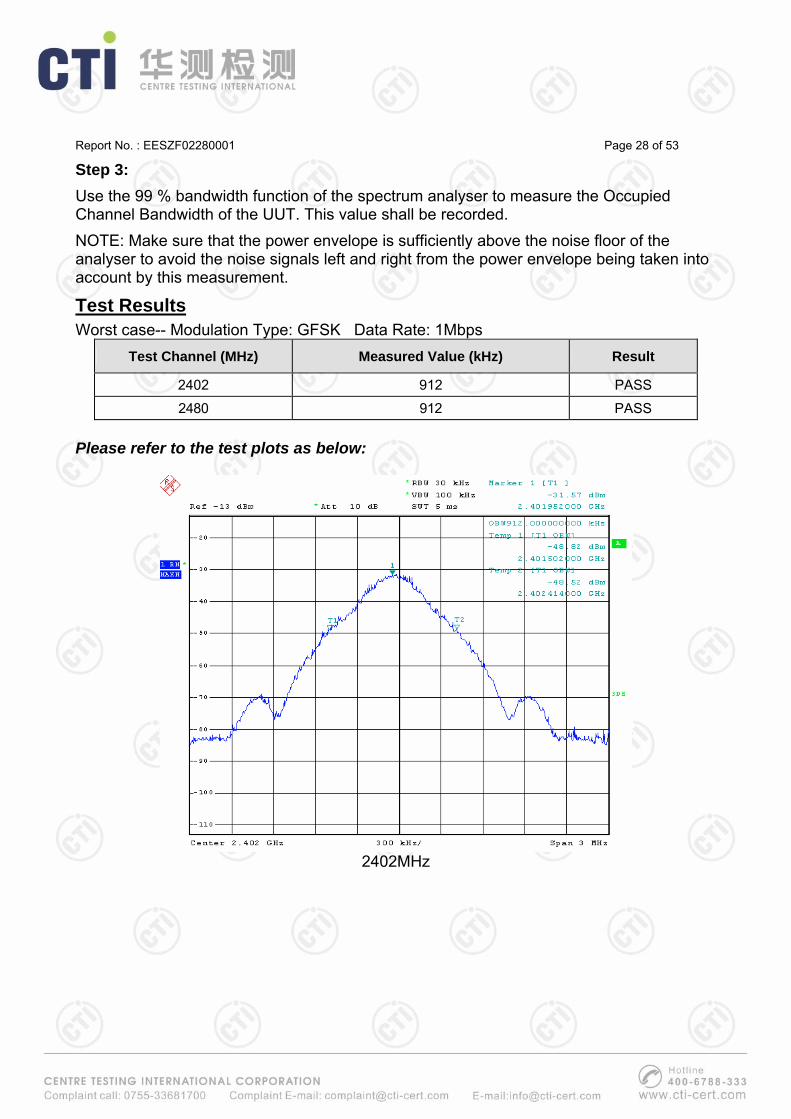
Step 3: Use the 99 % bandwidth function of the spectrum analyser to measure the Occupied Channel Bandwidth of the UUT. This value shall be recorded. NOTE: Make sure that the power envelope is sufficiently above the noise floor of the analyser to avoid the noise signals left and right from the power envelope being taken into account by this measurement.
Test Results Worst case-- Modulation Type: GFSK Data Rate: 1Mbps
Test Channel (MHz) Measured Value (kHz) Result
2402 912 PASS
2480 912 PASS Please refer to the test plots as below:
2402MHz

Report No. : EESZF02280001 Page 29 of 53
2480MHz
Report No. : EESZF02280001 Page 30 of 53
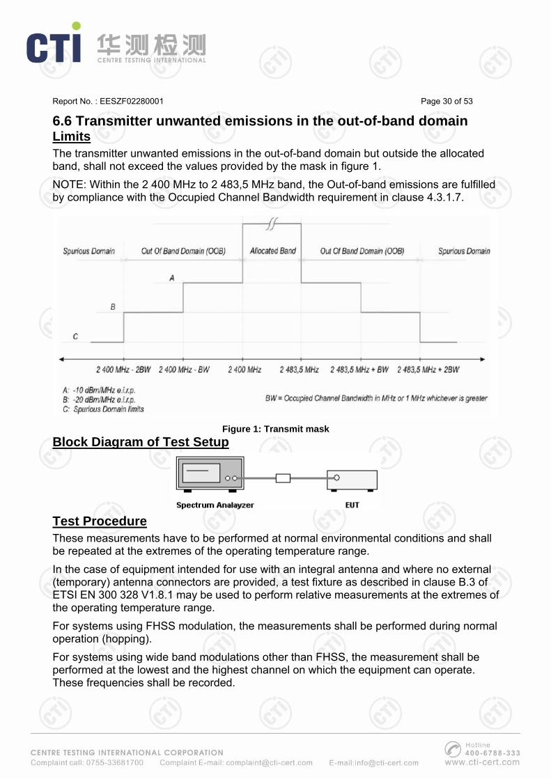
6.6 Transmitter unwanted emissions in the out-of-band domain Limits The transmitter unwanted emissions in the out-of-band domain but outside the allocated band, shall not exceed the values provided by the mask in figure 1. NOTE: Within the 2 400 MHz to 2 483,5 MHz band, the Out-of-band emissions are fulfilled by compliance with the Occupied Channel Bandwidth requirement in clause 4.3.1.7.
Figure 1: Transmit mask
Block Diagram of Test Setup
Test Procedure These measurements have to be performed at normal environmental conditions and shall be repeated at the extremes of the operating temperature range. In the case of equipment intended for use with an integral antenna and where no external (temporary) antenna connectors are provided, a test fixture as described in clause B.3 of ETSI EN 300 328 V1.8.1 may be used to perform relative measurements at the extremes of the operating temperature range. For systems using FHSS modulation, the measurements shall be performed during normal operation (hopping). For systems using wide band modulations other than FHSS, the measurement shall be performed at the lowest and the highest channel on which the equipment can operate. These frequencies shall be recorded.

Report No. : EESZF02280001 Page 31 of 53
The equipment shall be configured to operate under its worst case situation with respect to output power. Step 1: • Connect the UUT to the spectrum analyser and use the following settings: - Centre Frequency: 2 484 MHz - Span: 0 Hz - Resolution BW: 1 MHz - Filter mode: Channel filter - Video BW: 3 MHz - Detector Mode: RMS - Trace Mode: Clear / Write - Sweep Mode: Continuous - Sweep Points: 5 000 - Trigger Mode: Video trigger NOTE 1: In case video triggering is not possible, an external trigger source may be used. - Sweep Time: Suitable to capture one transmission burst Step 2: (segment 2 483,5 MHz to 2 483,5 MHz + BW) • Adjust the trigger level to select the transmissions with the highest power level. • For frequency hopping equipment operating in a normal hopping mode, the different hops will result in signal bursts with different power levels. In this case the burst with the highest power level shall be selected. • Set a window (start and stop lines) to match with the start and end of the burst and in which the RMS power shall be measured using the Time Domain Power function. • Select RMS power to be measured within the selected window and note the result which is the RMS power within this 1 MHz segment (2 483,5 MHz to 2 484,5 MHz). Compare this value with the applicable limit provided by the mask. • Increase the centre frequency in steps of 1 MHz and repeat this measurement for every 1 MHz segment within the range 2 483,5 MHz to 2 483,5 MHz + BW. The centre frequency of the last 1 MHz segment shall be set to 2 483,5 MHz + BW - 0,5 MHz (which means this may partly overlap with the previous 1 MHz segment). Step 3: (segment 2 483,5 MHz + BW to 2 483,5 MHz + 2BW) • Change the centre frequency of the analyser to 2 484 MHz + BW and perform the measurement for the first 1 MHz segment within range 2 483,5 MHz + BW to 2 483,5 MHz + 2BW. Increase the centre frequency in 1 MHz steps and repeat the measurements to cover this whole range. The centre frequency of the last 1 MHz segment shall be set to 2 483,5 MHz + 2 BW - 0,5 MHz.
Report No. : EESZF02280001 Page 32 of 53
Step 4: (segment 2 400 MHz - BW to 2 400 MHz) • Change the centre frequency of the analyser to 2 399,5 MHz and perform the measurement for the first 1 MHz segment within range 2 400 MHz - BW to 2 400 MHz Reduce the centre frequency in 1 MHz steps and repeat the measurements to cover this whole range. The centre frequency of the last 1 MHz segment shall be set to 2 400 MHz - 2BW + 0,5 MHz. Step 5: (segment 2 400 MHz - 2BW to 2 400 MHz - BW) • Change the centre frequency of the analyser to 2 399,5 MHz - BW and perform the measurement for the first 1 MHz segment within range 2 400 MHz - 2BW to 2 400 MHz - BW. Reduce the centre frequency in 1 MHz steps and repeat the measurements to cover this whole range. The centre frequency of the last 1 MHz segment shall be set to 2 400 MHz - 2BW + 0,5 MHz. Step 6: • In case of conducted measurements on equipment with a single transmit chain, the declared antenna assembly gain "G" in dBi shall be added to the results for each of the 1 MHz segments and compared with the limits provided by the mask given in figures 1. If more than one antenna assembly is intended for this power setting, the antenna with the highest gain shall be considered. • In case of conducted measurements on smart antenna systems (equipment with multiple transmit chains), the measurements need to be repeated for each of the active transmit chains. The declared antenna assembly gain "G" in dBi for a single antenna shall be added to these results. If more than one antenna assembly is intended for this power setting, the antenna with the highest gain shall be considered. Comparison with the applicable limits shall be done using any of the options given below: - Option 1: the results for each of the transmit chains for the corresponding 1 MHz segments shall be added. The additional beamforming gain "Y" in dB shall be added as well and the resulting values compared with the limits provided by the mask given in figures 1. - Option 2: the limits provided by the mask given in figures 1shall be reduced by 10 x log10(Ach) and the additional beamforming gain "Y" in dB. The results for each of the transmit chains shall be individually compared with these reduced limits. NOTE 2: Ach refers to the number of active transmit chains. It shall be recorded whether the equipment complies with the mask provided in figures 1.
Report No. : EESZF02280001 Page 33 of 53
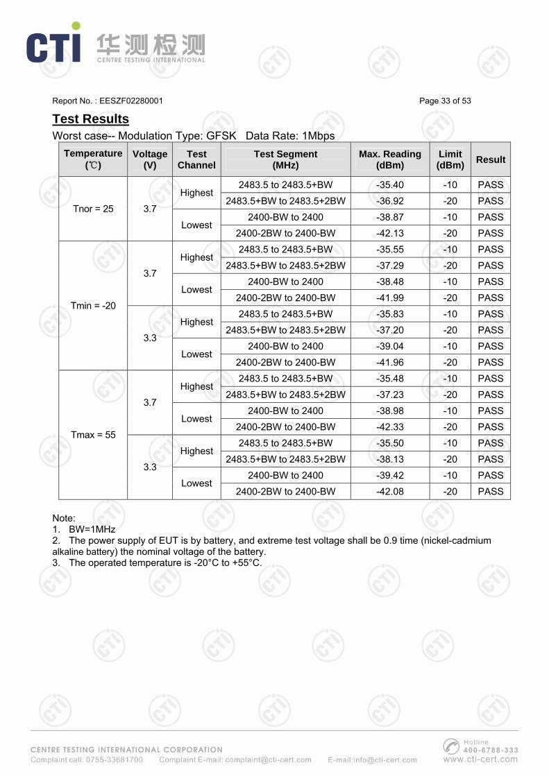
Test Results Worst case-- Modulation Type: GFSK Data Rate: 1Mbps
Temperature (℃)
Voltage(V)
Test Channel
Test Segment (MHz)
Max. Reading (dBm)
Limit (dBm) Result
2483.5 to 2483.5+BW -35.40 -10 PASSHighest
2483.5+BW to 2483.5+2BW -36.92 -20 PASS
2400-BW to 2400 -38.87 -10 PASSTnor = 25 3.7
Lowest 2400-2BW to 2400-BW -42.13 -20 PASS
2483.5 to 2483.5+BW -35.55 -10 PASSHighest
2483.5+BW to 2483.5+2BW -37.29 -20 PASS2400-BW to 2400 -38.48 -10 PASS
3.7 Lowest
2400-2BW to 2400-BW -41.99 -20 PASS
2483.5 to 2483.5+BW -35.83 -10 PASSHighest
2483.5+BW to 2483.5+2BW -37.20 -20 PASS
2400-BW to 2400 -39.04 -10 PASS
Tmin = -20
3.3 Lowest
2400-2BW to 2400-BW -41.96 -20 PASS2483.5 to 2483.5+BW -35.48 -10 PASS
Highest 2483.5+BW to 2483.5+2BW -37.23 -20 PASS
2400-BW to 2400 -38.98 -10 PASS3.7
Lowest 2400-2BW to 2400-BW -42.33 -20 PASS
2483.5 to 2483.5+BW -35.50 -10 PASSHighest
2483.5+BW to 2483.5+2BW -38.13 -20 PASS2400-BW to 2400 -39.42 -10 PASS
Tmax = 55
3.3 Lowest
2400-2BW to 2400-BW -42.08 -20 PASS Note: 1. BW=1MHz 2. The power supply of EUT is by battery, and extreme test voltage shall be 0.9 time (nickel-cadmium alkaline battery) the nominal voltage of the battery. 3. The operated temperature is -20°C to +55°C.
Report No. : EESZF02280001 Page 34 of 53
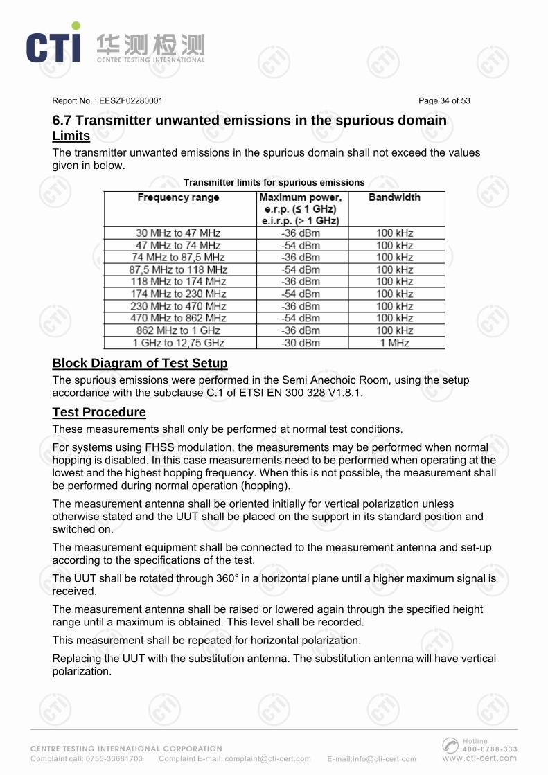
6.7 Transmitter unwanted emissions in the spurious domain Limits The transmitter unwanted emissions in the spurious domain shall not exceed the values given in below.
Transmitter limits for spurious emissions
Block Diagram of Test Setup The spurious emissions were performed in the Semi Anechoic Room, using the setup accordance with the subclause C.1 of ETSI EN 300 328 V1.8.1.
Test Procedure These measurements shall only be performed at normal test conditions. For systems using FHSS modulation, the measurements may be performed when normal hopping is disabled. In this case measurements need to be performed when operating at the lowest and the highest hopping frequency. When this is not possible, the measurement shall be performed during normal operation (hopping). The measurement antenna shall be oriented initially for vertical polarization unless otherwise stated and the UUT shall be placed on the support in its standard position and switched on. The measurement equipment shall be connected to the measurement antenna and set-up according to the specifications of the test. The UUT shall be rotated through 360° in a horizontal plane until a higher maximum signal is received. The measurement antenna shall be raised or lowered again through the specified height range until a maximum is obtained. This level shall be recorded. This measurement shall be repeated for horizontal polarization. Replacing the UUT with the substitution antenna. The substitution antenna will have vertical polarization.

Report No. : EESZF02280001 Page 35 of 53
Connect a signal generator to the substitution antenna, and adjust it to the measurement frequency. In SAR used, the measurement antenna shall be raised or lowered, to ensure that the maximum signal is received. Subsequently, the power of the signal generator is adjusted until the same level is obtained again at the measurement equipment. The radiated power is equal to the power supplied by the signal generator, increased the substitution antenna gain minus the cable losses (values in dB). This measurement shall be repeated with horizontal polarization. NOTE: For test sites with a fixed setup of the measurement antenna(es) and a reproducible positioning of the UUT, correction values from a verified site calibration can be used alternatively.
Test Results Temperature: 24oC Atmospheric pressure: 101kpa Humidity: 53% Tested by: Christy Chen Worst case-- Modulation Type: GFSK Data Rate: 1Mbps
Frequency Emission level Limit Margin Antenna(MHz) (dBm) (dBm) (dB) Polarization
3652.0 -57.1 -30 -27.1 H6356.0 -53.3 -30 -23.3 H7864.0 -53.7 -30 -23.7 H3652.0 -58.8 -30 -28.8 V7006.0 -52.7 -30 -22.7 V9008.0 -53.6 -30 -23.6 V
---
4406.0 -56.6 -30 -26.6 H6278.0 -53.7 -30 -23.7 H8618.0 -53.2 -30 -23.2 H4354.0 -58.3 -30 -28.3 V6382.0 -54.4 -30 -24.4 V8150.0 -54.5 -30 -24.5 V
---
Highest Channel
Lowest channel
Note: 1. The test frequency range is 30MHz to 12.75GHz. 2. If the test data is very low, the data is not reported.
Report No. : EESZF02280001 Page 36 of 53
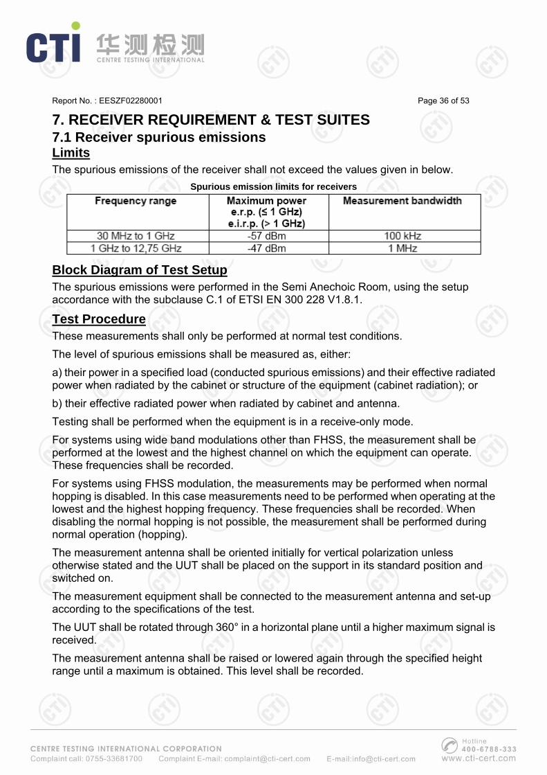
7. RECEIVER REQUIREMENT & TEST SUITES 7.1 Receiver spurious emissions Limits The spurious emissions of the receiver shall not exceed the values given in below.
Spurious emission limits for receivers
Block Diagram of Test Setup The spurious emissions were performed in the Semi Anechoic Room, using the setup accordance with the subclause C.1 of ETSI EN 300 228 V1.8.1.
Test Procedure These measurements shall only be performed at normal test conditions. The level of spurious emissions shall be measured as, either: a) their power in a specified load (conducted spurious emissions) and their effective radiated power when radiated by the cabinet or structure of the equipment (cabinet radiation); or b) their effective radiated power when radiated by cabinet and antenna. Testing shall be performed when the equipment is in a receive-only mode. For systems using wide band modulations other than FHSS, the measurement shall be performed at the lowest and the highest channel on which the equipment can operate. These frequencies shall be recorded. For systems using FHSS modulation, the measurements may be performed when normal hopping is disabled. In this case measurements need to be performed when operating at the lowest and the highest hopping frequency. These frequencies shall be recorded. When disabling the normal hopping is not possible, the measurement shall be performed during normal operation (hopping). The measurement antenna shall be oriented initially for vertical polarization unless otherwise stated and the UUT shall be placed on the support in its standard position and switched on. The measurement equipment shall be connected to the measurement antenna and set-up according to the specifications of the test. The UUT shall be rotated through 360° in a horizontal plane until a higher maximum signal is received. The measurement antenna shall be raised or lowered again through the specified height range until a maximum is obtained. This level shall be recorded.

Report No. : EESZF02280001 Page 37 of 53
This measurement shall be repeated for horizontal polarization. Replacing the UUT with the substitution antenna. The substitution antenna will have vertical polarization. Connect a signal generator to the substitution antenna, and adjust it to the measurement frequency. In SAR used, the measurement antenna shall be raised or lowered, to ensure that the maximum signal is received. Subsequently, the power of the signal generator is adjusted until the same level is obtained again at the measurement equipment. The radiated power is equal to the power supplied by the signal generator, increased the substitution antenna gain minus the cable losses (values in dB). This measurement shall be repeated with horizontal polarization. NOTE: For test sites with a fixed setup of the measurement antenna(es) and a reproducible positioning of the UUT, correction values from a verified site calibration can be used alternatively.
Test Results Temperature: 22oC Atmospheric pressure: 101kpa Humidity: 52% Tested by: Christy Chen Worst case-- Modulation Type: GFSK Data Rate: 1Mbps
Frequency Emission level Limit Margin Antenna(MHz) (dBm) (dBm) (dB) Polarization
--- --- --- --- --- --- --- --- --- --- --- --- --- --- --- --- --- --- --- --- --- --- --- --- --- --- --- --- --- ---
--- --- --- --- --- --- --- --- --- --- --- --- --- --- --- --- --- --- --- --- --- --- --- --- --- --- --- --- --- --- --- --- --- --- ---
Highest Channel
Lowest channel
Remark: 1. The test frequency from 30MHz up to 12.75GHz. 2. If the emission level is too low to be measured, it is not reported.

Report No. : EESZF02280001 Page 38 of 53
8. EMC REQUIREMENT & TEST SUITES 8.1 Immunity test results The performance criteria are:
• performance criteria A for immunity tests with phenomena of a continuous nature; • performance criteria B for immunity tests with phenomena of a transient nature; • performance criteria C for immunity tests with power interruptions exceeding a certain
time.
Criteria During test After test
A
Shall operate as intended. May show degradation of performance (see note 1). Shall be no loss of function. Shall be no unintentional transmissions.
Shall operate as intended. Shall be no degradation of performance (see note 2).Shall be no loss of function. Shall be no loss of stored data or user programmable functions.
B
May show loss of function (one or more).May show degradation of performance (see note 1). No unintentional transmissions.
Functions shall be self-recoverable. Shall operate as intended after recovering. Shall be no degradation of performance (see note 2).Shall be no loss of stored data or user programmable functions.
C May be loss of function (one or more). Functions shall be recoverable by the operator. Shall operate as intended after recovering. Shall be no degradation of performance (see note 2).
NOTE 1: Degradation of performance during the test is understood as a degradation to a level not below a minimum performance level specified by the manufacturer for the use of the apparatus as intended. In some cases the specified minimum performance level may be replaced by a permissible degradation of performance.
If the minimum performance level or the permissible performance degradation is not specified by the manufacturer then either of these may be derived from the product description and documentation (including leaflets and advertising) and what the user may reasonably expect from the apparatus if used as intended.
NOTE 2: No degradation of performance after the test is understood as no degradation below a minimum performance level specified by the manufacturer for the use of the apparatus as intended. In some cases the specified minimum performance level may be replaced by a permissible degradation of performance. After the test no change of actual operating data or user retrievable data is allowed.
If the minimum performance level or the permissible performance degradation is not specified by the manufacturer then either of these may be derived from the product description and documentation (including leaflets and advertising) and what the user may reasonably expect from the apparatus if used as intended.

Report No. : EESZF02280001 Page 39 of 53
According to the clause 6.3 of ETSI EN 301 489-17 V2.2.1, the description of performance criteria is below: Continuous phenomena applied to Transmitters (CT): The performance criteria A shall apply. Tests shall be repeated with the EUT in standby mode (if applicable) to ensure that unintentional transmission does not occur. In systems using acknowledgement signals, it is recognized that an ACKnowledgement (ACK) or Not ACKnowledgement (NACK) transmission may occur, and steps should be taken to ensure that any transmission resulting from the application of the test is correctly interpreted. Transient phenomena applied to Transmitters (TT): The performance criteria B shall apply, except for voltage dips of 100 ms and voltage interruptions of 5 000 ms duration, for which performance criteria C shall apply. Tests shall be repeated with the EUT in standby mode (if applicable) to ensure that unintentional transmission does not occur. In systems using acknowledgement signals, it is recognized that an acknowledgement (ACK) or not-acknowledgement (NACK) transmission may occur, and steps should be taken to ensure that any transmission resulting from the application of the test is correctly interpreted.
Continuous phenomena applied to Receivers (CR): The performance criteria A shall apply. Where the EUT is a transceiver, under no circumstances, shall the transmitter operate unintentionally during the test. In systems using acknowledgement signals, it is recognized that an ACK or NACK transmission may occur, and steps should be taken to ensure that any transmission resulting from the application of the test is correctly interpreted.
Transient phenomena applied to Receivers (TR): The performance criteria B shall apply, except for voltage dips of 100 ms and voltage interruptions of 5 000 ms duration for which performance criteria C shall apply. Where the EUT is a transceiver, under no circumstances, shall the transmitter operate unintentionally during the test. In systems using acknowledgement signals, it is recognized that an ACK or NACK transmission may occur, and steps should be taken to ensure that any transmission resulting from the application of the test is correctly interpreted.

Report No. : EESZF02280001 Page 40 of 53
8.1.1 RF electromagnetic field (RS) Test Specification Basic Standard : ETSI EN 301 489-17 & EN 61000-4-3 Step Size : 10% Modulation : 80% AM Dwell Time : 1 second
Polarization : Horizontal & Vertical
Test Setup a. Below 1GHz:
b. Above 1GHz

Report No. : EESZF02280001 Page 41 of 53
Test Procedure a. The testing was performed in a fully-anechoic chamber. The transmit antenna was located at a distance of 3m from the EUT.
b. The frequency range is swept from 80MHz to 1GHz and 1.4GHz to 2.7GHz, with the signal 80% amplitude modulated with a 1 kHz sine wave. The rate of sweep did not exceed 1.5x 10⁻³ decade/s. Where the frequency range is swept incrementally, the step size was 1%.
c. The dwell time at each frequency shall be not less than the time necessary for the EUT to be able to respond, and not exceed 5s at each of the frequencies during the scan.
d. The test was performed with the EUT exposed to both vertically and horizontally polarized fields on each of the four sides.
Test Results Product : Bluetooth Headset Model/Type reference : BT304 Power : DC 3.7V Temperature : 23oC Mode : TX & RX Humidity : 53%
Position Frequency Field
Strength(V/m)
RF Signal (Modulation)
Polarity(H/V)
Required Level (Pursuant to EN301489-17
Criterion CT & CR)
PerformanceCriterion
Front 80MHz-1GHz & 1.4GHz-2.7GHz 3 AM H/V A A
Left 80MHz-1GHz & 1.4GHz-2.7GHz 3 AM H/V A A
Back 80MHz-1GHz & 1.4GHz-2.7GHz 3 AM H/V A A
Right 80MHz-1GHz & 1.4GHz-2.7GHz 3 AM H/V A A
Remark: EUT operated as intended, no degradation of function.

Report No. : EESZF02280001 Page 42 of 53
8.1.2 Electrostatic discharge (ESD) Test Specification Basic Standard : ETSI EN 301 489-17 & EN 61000-4-2 Discharge Impedance : 330 ohm / 150 pF Discharge Mode : Single Discharge Discharge Period : 1 discharge per second
Test Setup
Test Procedure a. Electrostatic discharges were applied only to those points and surfaces of the EUT that are accessible to users during normal operation.
b. The test was performed with at least ten single discharges on the pre-selected points in the most sensitive polarity.
c. The time interval between two successive single discharges was at least 1 second.
d. The ESD generator was held perpendicularly to the surface to which the discharge was applied and the return cable was at least 0.2 meters from the EUT.
e. Contact discharges were applied to the non-insulating coating, with the pointed tip of the generator penetrating the coating and contacting the conducting substrate.
f. Air discharges were applied with the round discharge tip of the discharge electrode approaching the EUT as fast as possible (without causing mechanical damage) to touch the EUT. After each discharge, the ESD generator was removed from the EUT and re-triggered for a new single discharge. The test was repeated until all discharges were complete.
g. At least ten single discharges (in the most sensitive polarity) were applied to the Horizontal Coupling Plane at points on each side of the Product. The ESD generator was positioned vertically at a distance of 0.1 meters from the Product with the discharge electrode touching the HCP.
h. At least ten single discharges (in the most sensitive polarity) were applied to the center of one vertical edge of the Vertical Coupling Plane in sufficiently different positions that the four

Report No. : EESZF02280001 Page 43 of 53
faces of the Product were completely illuminated. The VCP (dimensions 0.5m x 0.5m) was placed vertically to and 0.1 meters from the Product.
Test Results Product : Bluetooth Headset Model/Type reference : BT304 Power : DC 3.7V Temperature : 23oC Mode : TX & RX Humidity : 53%
Amount of Discharges Voltage Coupling
Required Level (Pursuant to EN301489-17
Criterion TT & TR)
Performance Criterion
Mini 10 /Point ± 2; ±4; ±8 kV Air Discharge B A
Mini 10 /Point ± 2; ±4 kV Contact Discharge B A
Mini 10 /Point ± 2; ±4 kV Indirect Discharge HCP B A
Mini 10 /Point ± 2; ±4 kV Indirect Discharge VCP B A Remark: EUT operated as intended, no degradation of function.
Report No. : EESZF02280001 Page 44 of 53
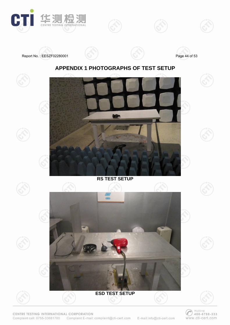
APPENDIX 1 PHOTOGRAPHS OF TEST SETUP
RS TEST SETUP
ESD TEST SETUP

Report No. : EESZF02280001 Page 45 of 53
APPENDIX 2 PHOTOGRAPHS OF EUT
Fig.1- General Front View (Model BT304)
Fig.2- General Back View (Model BT304)

Report No. : EESZF02280001 Page 46 of 53
Fig.3- Inner View (Model BT304)
Fig.4- PCB With Build-in Battery View (The Right Side Model BT304)

Report No. : EESZF02280001 Page 47 of 53
Fig.5- PCB View (The Right Side Model BT304)
Fig.6- PCB View (The Left Side Model BT304)
Report No. : EESZF02280001 Page 48 of 53
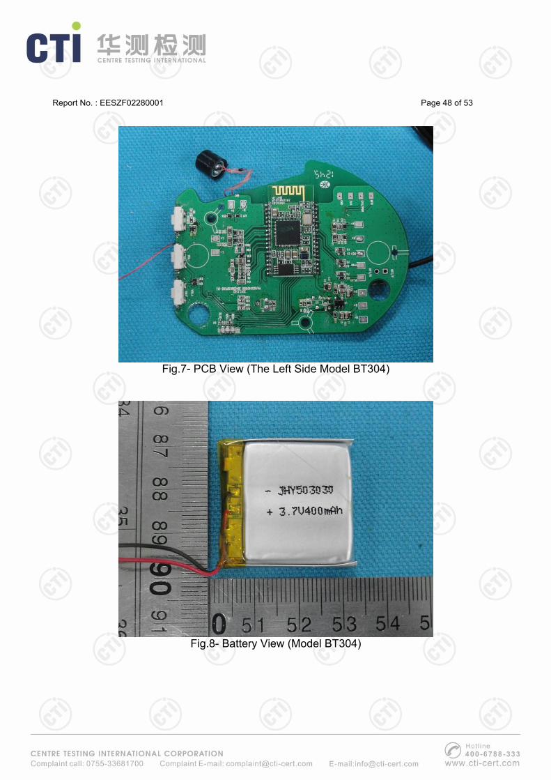
Fig.7- PCB View (The Left Side Model BT304)
Fig.8- Battery View (Model BT304)

Report No. : EESZF02280001 Page 49 of 53
Fig.9- General View (Model BT303)
Fig.10- General View (Model BT305)

Report No. : EESZF02280001 Page 50 of 53
Fig.11- General View (Model BT306)
Fig.12- General View (Model BT307)

Report No. : EESZF02280001 Page 51 of 53
Fig.13- General View (Model BT308)
Fig.14- Inner View (Model BT308)

Report No. : EESZF02280001 Page 52 of 53
Fig.15- General View (Model BT309)
Fig.16- General View (Model BT806)

Report No. : EESZF02280001 Page 53 of 53
Fig.17- General View (Model BT860)
----End of the report----
The test report is effective only with both signature and specialized stamp, The result(s) shown in this report refer only to the sample(s) tested. Without written approval of CTI, this report can’t be reproduced except in full.