test report iec 60884-1:2002 (third …§»动插座测试报告a系列.pdfiec 60884-1+ iec...
TRANSCRIPT

Page 1 of 46 Ref. No: SCC(10)-1111-10-LVD
TEST REPORT IEC 60884-1:2002 (Third edition)+A1:2006 IEC 60 884-2-2:2006
Plugs and socket-outlets for household and similar purposes Part 1: General requirements
Part 2: Particular requirements for socket-outlets for appliances
Report Reference No. .................... : SCC(10)-1111-10-LVD
Tested by (name + signature) .......... :
Reviewed by (name + signature) .... : Approved by (name + signature)...... : Date of issue .................................... : 18, Jun. 2010
Testing Laboratory......................... : CHINA CEPREI (SICHUAN) LABORATORY.
Address ............................................ : No.45 Wenming Dong Road Longquanyi Chengdu 610100 P. R. China
Testing location/ address ................. : No.45 Wenming Dong Road Longquanyi Chengdu 610100 P. R. China
Client
Name………………………………….: HANGZHOU GRANDIX ELECTRONICS CO., LTD
Address ............................................ : R.1-1804 NEW YOUTH PLAZA, NO.8 JIASHAN RD., HANGZHOU
Test specification:
Standard........................................... : IEC 60884-1:2002 (Third edition)+A1:2006 IEC 60 884-2-2:2006
Test procedure ................................. : LVD
Non-standard test method…………..: N/A
Test Report Form No...................... : IEC60884_2_2B
Test Report Form(s) Originator ........ : CHINA CEPREI (SICHUAN) LABORATORY.
Master TRF ...................................... : Dated 2007-09
Copyright blank test report CHINA CEPREI (SICHUAN) LABORATORY.
Test item description .....................: Multi-outlet Trailing Socket
Trade Mark ....................................... : TREEM
Manufacturer .................................... : HANGZHOU GRANDIX ELECTRONICS CO., LTD.
Model/Type reference ...................... : TRM-A5010
Ratings ............................................. : Voltage: ~250V Current : 16A 50/60Hz
Power : Max. 3800W
Page 2 of 46 SCC(10)-1111-10-LVD
TRF No.: IEC60884_2_2B
Test item particulars:
Rated current (A) / Rated voltage (V) .....................: ~250V~ 16A
Degree of protection against access to hazardous parts and against harmful ingress of solid foreign objects .....................................................................:
IP2X
Degree of protection against harmful ingress of water ........................................................................: IPX0
Provision for earthing ..............................................: with earthing contact Method of connecting the cable ..............................: non-rewirable Nominal cross-sectional areas (mm2) .....................: 1.0 mm2
Possible test case verdicts:
Test case does not apply to the test object .............: N/A
Test object does meet the requirement ..................: Pass (P)
Test object does not meet the requirement ............: Fail (F)
Testing:
Date of receipt of test item ......................................: 7, Jun. 2010
Date(s) of performance of test ................................: 7, Jun. 2010 – 17, Jun. 2010
General remarks: “(see remark #)” refers to a remark appended to the report. “(see appended table)” refers to a table appended to the report. Throughout this report a comma is used as the decimal separator. The test results presented in this report relate only to the object tested. This report shall not be reproduced except in full without the written approval of the testing laboratory.
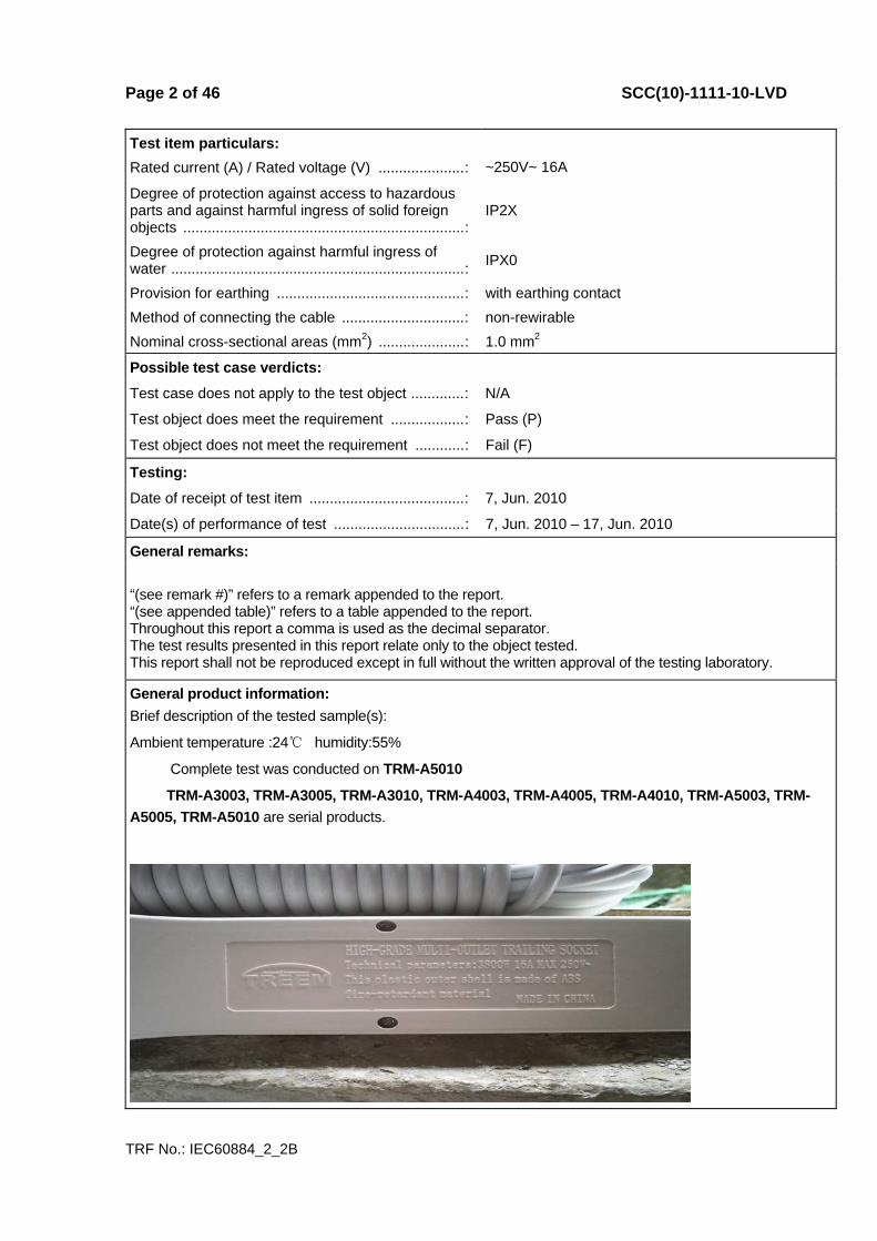
General product information: Brief description of the tested sample(s):
Ambient temperature :24℃ humidity:55%
Complete test was conducted on TRM-A5010
TRM-A3003, TRM-A3005, TRM-A3010, TRM-A4003, TRM-A4005, TRM-A4010, TRM-A5003, TRM-A5005, TRM-A5010 are serial products.

Page 3 of 46 SCC(10)-1111-10-LVD
IEC 60884-1+ IEC 60884-2-2:2006Clause Requirement – Test Result - Remark Verdict
TRF No.: IEC60884_2_2B
8 MARKING ⎯ 8.1 Accessories marked as follows: P
- rated current (A) ..................................................... : 16A P
- rated voltage (V) .................................................... : 250V P
- symbol for nature of supply ................................... : ~ P
- manufacturer’s or responsible vendor’s name ..... : TREEM P
- type reference ........................................................ : TRM-A5010 P
- symbol for degree of protection (first digit) ........... : 2 P
- symbol for degree of protection (second digit) ..... : 0 P
Socket-outlets with screwless terminals marked with the following: N
- the length of insulation to be removed .................. : N
- an indication of the suitability to accept rigid conductors only (if any) ............................................ :
N
- socket-outlets for appliances: provided with flat, quick-connect terminations and screw-type or screwless terminals supplied with an instruction sheet, attached to the smallest packaging unit, informing the user that flat, quick-connect terminations shall not be used for fixed installations (See IEC 60884-2-2 sub-clause 7.1) ...................... :
N
8.2 Symbols used: as required in the standard P
Marking for the nature of supply placed next to the marking for rated current and rated voltage
250V~ 16A P
8.3 Marking of fixed socket-outlets placed on the main part: N
- rated current, rated voltage and nature of supply N
- identification mark of the manufacturer or of the responsible vendor
N
- length of insulation to be removed, if any N
- type reference N
Cover plates necessary for safety purposes and intended to be sold separately: marked with the manufacturer’s or responsible vendor’s name and type reference
N
IP code, if applicable: marked so as to be easily discernible
N
Fixed socket-outlets classified according to item b) of 7.2.5: identified by a triangle visible after installation unless they have an interface configuration different from that used in normal circuits ............................. :
N

Page 4 of 46 SCC(10)-1111-10-LVD
IEC 60884-1+ IEC 60884-2-2:2006Clause Requirement – Test Result - Remark Verdict
TRF No.: IEC60884_2_2B
8.4 Plugs and portable socket-outlets: marking specified in 8.1, other than the type reference, easily discernible
Easily discernible P
Plugs and portable socket-outlets for equipment of class II not marked with the symbol for class II construction
Class I N
8.5 Neutral terminals: N ................................................. : Have ”N” the mark P
Earthing terminals: [earth symbol] ........................... : P
Markings not placed on screws or other easily removable parts
Pass muster P
Terminals for conductors not forming part of the main function of the socket-outlet: N
- clearly identified unless their purpose is self evident, or
N
- indicated in a wiring diagram fixed to the accessory N
Identification of such terminals may be achieved by: N
- their being marked with graphical symbols according to IEC 60417-2 or colours and/or alphanumeric system, or
N
- their being marked with their physical dimensions or relative location
N
8.6 Surface-type mounting boxes forming an integral part of socket-outlets having IP>20: IP code marked on the outside of its associated enclosure so as to be easily discernible
IP2X N
8.7 Indication of which position or with which special provision the declared IP of flush-type and semi-flush-type fixed socket-outlets having IP>X0 is ensured
IPX0 N
8.8 Marking durable and easily legible. Test: 15 s with water and 15 s with petroleum spirit
Easily legible and durable
P
9 CHECKING OF DIMENSIONS ⎯ 9.1 Accessories and surface-type mounting boxes
comply with the appropriate standard sheets Accord with requirement of standard
P
Insertion of plugs into fixed or portable socket-outlets ensured by their compliance with the relevant standard sheets
Pass muster P
Compliance checked by measurement and by means of gauges with manufacturing tolerances as shown in table 2
Comply with the requirements P
9.2 It is not possible to engage a plug with: ⎯
- a socket-outlet having a higher voltage rating or a lower current rating
N

Page 5 of 46 SCC(10)-1111-10-LVD
IEC 60884-1+ IEC 60884-2-2:2006Clause Requirement – Test Result - Remark Verdict
TRF No.: IEC60884_2_2B
- a socket-outlet with a different number of live poles (exception admitted provided that no dangerous situation can arise)
Pass muster P
- a socket-outlet with earthing contact (plug for class 0 equipment)
P
Engagement of a plug for class 0 or class I equipment with a socket-outlet designed to accept plugs for class II equipment, not possible
P
Impossibility of insertion checked by applying a gauge, for 1 min, with a force of: N
- 150 N (rated current ≤ 16A) P
- 250 N (rated current > 16A) N
Accessories with elastomeric or thermoplastic material: test carried out at (35 ± 2) °C
P
9.3 Deviations from standard sheets made only if they provide technical advantage and do not affect the purpose and safety of accessories complying with standard sheet
P
10 PROTECTION AGAINST ELECTRIC SHOCK ⎯ 10.1 Socket-outlets: live parts not accessible P
Live parts of plugs: not accessible when the plug is in partial or complete engagement with a socket-outlet
Pass muster P
Test with test probe B of IEC 61032 Comply with the requirements P
Accessories with elastomeric or thermoplastic material: additional test carried out at (35 ± 2) °C with test probe 11 of IEC 61032 (75 N for 1 min)
Pass muster Comply with the requirements
P
During the test: accessories not deform and no live parts accessible
Don’t deform and don’t be accessible
P
Plugs and portable socket-outlets pressed with a force of 150 N for 5 min as shown in figure 8: specimens not show deformation
No danger Pass muster
P
10.2 Accessible parts (with exception of small screws and the like for fixing bases and covers or cover plates): made of insulating material
P
Cover or cover plates of fixed socket-outlets and accessible parts of plugs and portable socket-outlets: made of metal if the requirements of 10.2.1 or 10.2.2 are fulfilled
N
10.2.1 Metal covers or cover plates protected by supplementary insulation made by insulating linings or insulating barriers
N
Insulating linings or insulating barriers cannot be removed without being permanently damaged
N
Page 6 of 46 SCC(10)-1111-10-LVD
IEC 60884-1+ IEC 60884-2-2:2006Clause Requirement – Test Result - Remark Verdict
TRF No.: IEC60884_2_2B
Insulating linings or insulating barriers cannot be replaced in an incorrect position and, if they are omitted, accessories are rendered inoperable or manifestly incomplete
N
There is no risk of accidental contact between live parts and metal covers or cover plates
N
10.2.2 Metal covers or cover plates automatically connected, through a low-resistance connection, to the earth during fixing
N
10.3 Contact between a pin of a plug and a live socket-contact of a socket-outlet not possible while any other pin is accessible
P
Compliance checked by manual test and by means of gauges with tolerances as specified in table 2
P
Accessories with elastomeric or thermoplastic material: test carried out at (35 ± 2) °C
Pass muster P
Socket-outlets with enclosure or bodies of rubber or polyvinyl chloride: test carried out with a force of 75 N for 1 min
Pass muster P
Fixed socket-outlets provided with metal covers or cover plates: clearance of at least 2 mm required between a pin and a socket-contact when another pin(s) is (are) in contact with the metal covers or cover plates .............................................................. :
N
10.4 External parts of plugs made of insulating material P
Overall dimensions of rings around pins not exceed 8 mm concentric with respect to the pin
P
10.5 Shuttered socket-outlets: live parts not accessible, without a plug in engagement, with the gauges shown in figure 9 and 10
N
Live contacts automatically screened when the plug is withdrawn
N
Means cannot easily be operated by anything other than a plug and not depend upon parts which are liable to be lost
N
Gauge of figure 9, applied to the entry holes corresponding to live contacts with a force of 20 N, for approximately 5 s, successively in three directions, does not touch live parts
N
Steel gauge of figure 10, applied to the entry holes corresponding to live contacts with a force of 1 N for approximately 5 s, in three directions, does not touch live parts
N
Accessories with elastomeric or thermoplastic material: test carried out at (35 ± 2) °C
N
Page 7 of 46 SCC(10)-1111-10-LVD
IEC 60884-1+ IEC 60884-2-2:2006Clause Requirement – Test Result - Remark Verdict
TRF No.: IEC60884_2_2B
10.6 Earthing contacts of a socket-outlet designed that they cannot be deformed by the insertion of a plug
P
Test plug inserted into the socket-outlet with a force of 150 N for 1 min P
After this test: socket-outlet still comply with the requirements of clause 9
Pass muster P
10.7 Socket-outlet with increased protection: live parts not accessible
P
Test wire of 1 mm diameter (figure 10) applied with a force of 1 N on all accessible surfaces does not touch live parts
P
Accessories with elastomeric or thermoplastic material: test carried out at (35 ± 2) °C
P
11 PROVISION FOR EARTHING ⎯ 11.1 Earth connection made before the current-carrying
contacts of the plug become live Pass muster P
Current-carrying pins are separated before the earth connection is broken
Pass muster P
11.2 Earthing terminals of rewirable accessories comply with clause 12
N
Earthing terminals of the same size as the corresponding terminals for the supply conductors
N
Earthing terminals of rewirable accessories: internal N
Additional external earthing terminal of fixed socket-outlets of size suitable for conductors of at least 6 mm2 .......................................................................... :
N
Earthing terminals of fixed socket-outlets: fixed to the base or to a part reliably fixed to the base
N
Earthing contacts of fixed socket-outlets: N
- fixed to the base, or N
- fixed to the cover (reliably connected to the earthing terminals; contact pieces silver plated or with adequate protection)
N
Parts of earthing circuit in one piece or reliably connected by riveting, welding, or the like
N
11.3 Accessible metal parts of fixed socket-outlets: permanently and reliably connected to the earthing terminal
N
11.4 Socket-outlets, having an IP>X0, with enclosure of insulating material and more than one cable inlet, provided with:
N
- an internal fixed earthing terminal, or N
Page 8 of 46 SCC(10)-1111-10-LVD
IEC 60884-1+ IEC 60884-2-2:2006Clause Requirement – Test Result - Remark Verdict
TRF No.: IEC60884_2_2B
- adequate space for a floating terminal (test connection using the type of terminal specified by the manufacturer), unless
N
- earthing terminal of socket-outlet itself allows the connection of an incoming and an outgoing earthing conductor
N
11.5 Connection between earthing terminal and accessible metal parts: of low resistance
P
Test: P
Test current equal to 1,5 times the rated current or 25 A (A) .................................................................... :
Test current:25 A P
Resistance not exceed 0,05 Ω (Ω) .......................... : 0,007Ω
P
11.6 Fixed socket-outlets according to item b) of 7.2.5: earthing socket contact and its terminal electrically separated from any metal mounting means or other exposed conductive parts which may be connected to the protective earthing circuit of the installation
N
12 TERMINALS AND TERMINATIONS P All the test on terminals, with the exception of the
tests of 12.3 11 and 12.3.12, made after the test of clause 16
Pass muster Comply with the requirements
P
12.1 General P
12.1.1 Rewirable fixed socket-outlets provided with screw-type terminals or with screwless terminals .............. :
N
Socket-outlets for appliances provided with screw-type terminals, screwless terminals and/or male tabs of flat, quick-connect terminations (See IEC 60884-2-2 sub-clause 11.1.1) ................................................ :
P
Rewirable plugs and portable socket-outlets provided with terminals with screw clamping .......... :
P
Pre-soldered flexible conductors used: pre-soldered area outside the clamp area of screw-type terminals
P
Clamping means of terminals: not serve to fix any other components
P
12.1.2 Non-rewirable accessories provided with soldered, welded, crimped or equally effective permanent connections (termination) ........................................ :
P
Screwed or snap-on connections not used N
Connections made by crimping a pre-soldered flexible conductor not permitted
N
12.2 Terminals with screw clamping for external copper conductors N
Page 9 of 46 SCC(10)-1111-10-LVD
IEC 60884-1+ IEC 60884-2-2:2006Clause Requirement – Test Result - Remark Verdict
TRF No.: IEC60884_2_2B
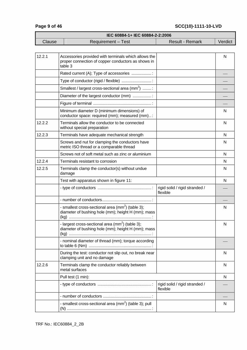
12.2.1 Accessories provided with terminals which allows the proper connection of copper conductors as shows in table 3
N
Rated current (A); Type of accessories .................. : ⎯
Type of conductor (rigid / flexible) ........................... : ⎯
Smallest / largest cross-sectional area (mm2) ........ : ⎯
Diameter of the largest conductor (mm) ................. : ⎯
Figure of terminal ..................................................... : ⎯
Minimum diameter D (minimum dimensions) of conductor space: required (mm); measured (mm).. :
N
12.2.2 Terminals allow the conductor to be connected without special preparation
N
12.2.3 Terminals have adequate mechanical strength N
Screws and nut for clamping the conductors have metric ISO thread or a comparable thread
N
Screws not of soft metal such as zinc or aluminium N
12.2.4 Terminals resistant to corrosion N
12.2.5 Terminals clamp the conductor(s) without undue damage
N
Test with apparatus shown in figure 11: N
- type of conductors ................................................. : rigid solid / rigid stranded / flexible
⎯
- number of conductors............................................. : ⎯
- smallest cross-sectional area (mm2) (table 3); diameter of bushing hole (mm); height H (mm); mass (kg) ........................................................................... :
N
- largest cross-sectional area (mm2) (table 3); diameter of bushing hole (mm); height H (mm); mass (kg) ........................................................................... :
N
- nominal diameter of thread (mm); torque according to table 6 (Nm) ......................................................... :
⎯
During the test: conductor not slip out, no break near clamping unit and no damage
N
12.2.6 Terminals clamp the conductor reliably between metal surfaces
N
Pull test (1 min): N
- type of conductors ................................................. : rigid solid / rigid stranded / flexible
⎯
- number of conductors ............................................ : ⎯
- smallest cross-sectional area (mm2) (table 3); pull (N) ............................................................................. :
N

Page 10 of 46 SCC(10)-1111-10-LVD
IEC 60884-1+ IEC 60884-2-2:2006Clause Requirement – Test Result - Remark Verdict
TRF No.: IEC60884_2_2B
- largest cross-sectional area (mm2) (table 3); pull (N) ............................................................................. :
N
- torque (Nm) (2/3 table 6) ....................................... : ⎯
During the test: conductor not move noticeably N
12.2.7 Terminals designed or placed that the conductor cannot slip out while the clamping screws or nuts are tightened
N
- largest cross-sectional area (mm2) (table 3) ......... : ⎯
- number of wires and nominal diameter of wires (table 5): N
Fixed socket-outlets: rigid solid conductors / rigid stranded conductors ................................................ :
⎯
Plugs and portable socket-outlets: flexible conductors ................................................................ :
⎯
- terminals intended for looping-in 2 or 3 conductors: permissible number of conductors ........................... :
⎯
- torque (Nm) (2/3 table 6) ....................................... : ⎯
After the test: no wire of the conductor escaped from the clamping unit
N
12.2.8 Terminals not work loose from their fixing to accessories
N
Torque test: N
- rigid solid copper conductor of the largest cross-sectional area (mm2) (table 3) ................................. :
⎯
- torque (Nm) (table 6 or appropriate figures 2, 3 or 4) .............................................................................. :
⎯
Screws and nuts tightened and loosened 5 times. During the test: terminals not work loose and show no damage
N
12.2.9 Clamping screws or nuts of earthing terminals: adequately locked against accidental loosening, not possible to loosen them without the aid of a tool
N
12.2.10 Earthing terminals: no risk of corrosion N
Body of brass or other metal no less resistant to corrosion
N
The body is a part of a frame or enclosure of aluminium alloy: precautions are taken to avoid the risk of corrosion
N
12.2.11 Pillar terminals: distance g no less than the value specified in figure 2: required (mm); measured (mm) ................................................................................... :
N
Mantle terminals: distance g no less than the value specified in figure 5: required (mm); measured (mm) ................................................................................... :
N
Page 11 of 46 SCC(10)-1111-10-LVD
IEC 60884-1+ IEC 60884-2-2:2006Clause Requirement – Test Result - Remark Verdict
TRF No.: IEC60884_2_2B
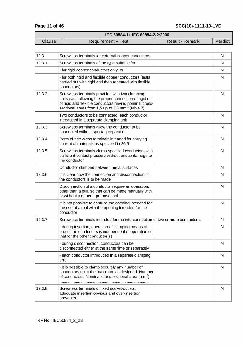
12.3 Screwless terminals for external copper conductors N
12.3.1 Screwless terminals of the type suitable for: N
- for rigid copper conductors only, or N
- for both rigid and flexible copper conductors (tests carried out with rigid and then repeated with flexible conductors)
N
12.3.2 Screwless terminals provided with two clamping units each allowing the proper connection of rigid or of rigid and flexible conductors having nominal cross-sectional areas from 1,5 up to 2,5 mm 2 (table 7)
N
Two conductors to be connected: each conductor introduced in a separate clamping unit
N
12.3.3 Screwless terminals allow the conductor to be connected without special preparation
N
12.3.4 Parts of screwless terminals intended for carrying current of materials as specified in 26.5
N
12.3.5 Screwless terminals clamp specified conductors with sufficient contact pressure without undue damage to the conductor
N
Conductor clamped between metal surfaces N
12.3.6 It is clear how the connection and disconnection of the conductors is to be made
N
Disconnection of a conductor require an operation, other than a pull, so that can be made manually with or without a general-purpose tool
N
It is not possible to confuse the opening intended for the use of a tool with the opening intended for the conductor
N
12.3.7 Screwless terminals intended for the interconnection of two or more conductors: N
- during insertion, operation of clamping means of one of the conductors is independent of operation of that for the other conductor(s)
N
- during disconnection, conductors can be disconnected either at the same time or separately
N
- each conductor introduced in a separate clamping unit
N
- it is possible to clamp securely any number of conductors up to the maximum as designed. Number of conductors; Nominal cross-sectional area (mm2) ................................................................................... :
N
12.3.8 Screwless terminals of fixed socket-outlets: adequate insertion obvious and over-insertion prevented
N
Page 12 of 46 SCC(10)-1111-10-LVD
IEC 60884-1+ IEC 60884-2-2:2006Clause Requirement – Test Result - Remark Verdict
TRF No.: IEC60884_2_2B
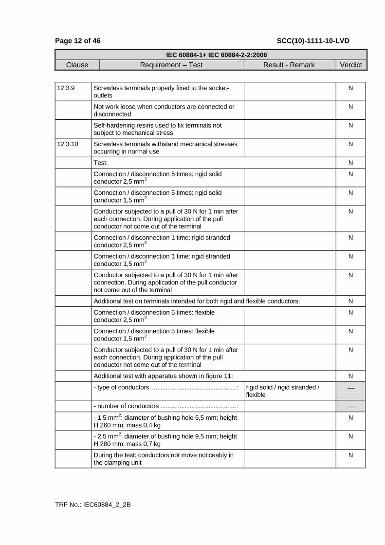
12.3.9 Screwless terminals properly fixed to the socket-outlets
N
Not work loose when conductors are connected or disconnected
N
Self-hardening resins used to fix terminals not subject to mechanical stress
N
12.3.10 Screwless terminals withstand mechanical stresses occurring in normal use
N
Test: N
Connection / disconnection 5 times: rigid solid conductor 2,5 mm2
N
Connection / disconnection 5 times: rigid solid conductor 1,5 mm2
N
Conductor subjected to a pull of 30 N for 1 min after each connection. During application of the pull conductor not come out of the terminal
N
Connection / disconnection 1 time: rigid stranded conductor 2,5 mm2
N
Connection / disconnection 1 time: rigid stranded conductor 1,5 mm2
N
Conductor subjected to a pull of 30 N for 1 min after connection. During application of the pull conductor not come out of the terminal
N
Additional test on terminals intended for both rigid and flexible conductors: N
Connection / disconnection 5 times: flexible conductor 2,5 mm2
N
Connection / disconnection 5 times: flexible conductor 1,5 mm2
N
Conductor subjected to a pull of 30 N for 1 min after each connection. During application of the pull conductor not come out of the terminal
N
Additional test with apparatus shown in figure 11: N
- type of conductors ................................................. : rigid solid / rigid stranded / flexible
⎯
- number of conductors ............................................ : ⎯
- 1,5 mm2; diameter of bushing hole 6,5 mm; height H 260 mm; mass 0,4 kg
N
- 2,5 mm2; diameter of bushing hole 9,5 mm; height H 280 mm; mass 0,7 kg
N
During the test: conductors not move noticeably in the clamping unit
N

Page 13 of 46 SCC(10)-1111-10-LVD
IEC 60884-1+ IEC 60884-2-2:2006Clause Requirement – Test Result - Remark Verdict
TRF No.: IEC60884_2_2B
After these tests: neither terminals nor clamping means have worked loose and conductors show no deterioration
N
12.3.11 Screwless terminals withstand electrical and thermal stresses occurring in normal use
N
Test a) carried out for 1 h connecting rigid solid conductors: N
- test current (A) (table 10) ...................................... : ⎯
- nominal cross-sectional area (mm2) ..................... : ⎯
- screwless terminal number ................................... : 1 2 3 4 5 ⎯
- voltage drop measured (mV) (requirement: ≤ 15 mV) ........................................................................... :
N
Test b) (temperature cycles test) carried out on terminals subjected to Test a): N
- test current (A) (table 10) ...................................... : ⎯
- cross-sectional area (mm2) ................................... : ⎯
- screwless terminal number .................................... : 1 2 3 4 5 ⎯
- voltage drop measured after the 24 cycle (requirement: ≤ 22,5 mV) ......................................... :
N
- voltage drop measured (mV) after 48th cycle ........ : N
- voltage drop measured (mV) after 72th cycle ........ : N
- voltage drop measured (mV) after 96th cycle ........ : N
- voltage drop measured (mV) after 120th cycle ...... : N
- voltage drop measured (mV) after 144th cycle ...... : N
- voltage drop measured (mV) after 168th cycle ...... : N
- voltage drop measured (mV) after 192th cycle ...... : N
- requirement: ≤ 22,5 mV or twice the value measured after the 24th cycle (mV) ......................... :
N
After this test: inspection show no changes N
Mechanical strength test according 12.3.10: N
Connection / disconnection 5 times: rigid solid conductor 2,5 mm2
N
Connection / disconnection 5 times: rigid solid conductor 1,5 mm2
N
Conductor subjected to a pull of 30 N for 1 min after each connection. During application of the pull conductor not come out of the terminal
N
Connection / disconnection 1 time: rigid stranded conductor 2,5 mm2
N
Connection / disconnection 1 time: rigid stranded conductor 1,5 mm2
N
Page 14 of 46 SCC(10)-1111-10-LVD
IEC 60884-1+ IEC 60884-2-2:2006Clause Requirement – Test Result - Remark Verdict
TRF No.: IEC60884_2_2B
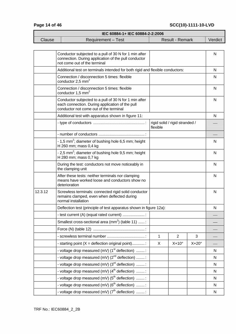
Conductor subjected to a pull of 30 N for 1 min after connection. During application of the pull conductor not come out of the terminal
N
Additional test on terminals intended for both rigid and flexible conductors: N
Connection / disconnection 5 times: flexible conductor 2,5 mm2
N
Connection / disconnection 5 times: flexible conductor 1,5 mm2
N
Conductor subjected to a pull of 30 N for 1 min after each connection. During application of the pull conductor not come out of the terminal
N
Additional test with apparatus shown in figure 11: N
- type of conductors ................................................. : rigid solid / rigid stranded / flexible
⎯
- number of conductors ............................................ : ⎯
- 1,5 mm2; diameter of bushing hole 6,5 mm; height H 260 mm; mass 0,4 kg
N
- 2,5 mm2; diameter of bushing hole 9,5 mm; height H 280 mm; mass 0,7 kg
N
During the test: conductors not move noticeably in the clamping unit
N
After these tests: neither terminals nor clamping means have worked loose and conductors show no deterioration
N
12.3.12 Screwless terminals: connected rigid solid conductor remains clamped, even when deflected during normal installation
N
Deflection test (principle of test apparatus shown in figure 12a): N
- test current (A) (equal rated current) ..................... : ⎯
Smallest cross-sectional area (mm2) (table 11) ...... : ⎯
Force (N) (table 12) ................................................. : ⎯
- screwless terminal number .................................... : 1 2 3 ⎯
- starting point (X = deflection original point)............ : X X+10° X+20° ⎯
- voltage drop measured (mV) (1st deflection) ........ : N
- voltage drop measured (mV) (2nd deflection) ........ : N
- voltage drop measured (mV) (3rd deflection) ........ : N
- voltage drop measured (mV) (4th deflection) ........ : N
- voltage drop measured (mV) (5th deflection) ........ : N
- voltage drop measured (mV) (6th deflection) ........ : N
- voltage drop measured (mV) (7th deflection) ........ : N

Page 15 of 46 SCC(10)-1111-10-LVD
IEC 60884-1+ IEC 60884-2-2:2006Clause Requirement – Test Result - Remark Verdict
TRF No.: IEC60884_2_2B
- voltage drop measured (mV) (8th deflection) ........ : N
- voltage drop measured (mV) (9th deflection) ........ : N
- voltage drop measured (mV) (10th deflection) ....... : N
- voltage drop measured (mV) (11th deflection) ...... : N
- voltage drop measured (mV) (12th deflection) ...... : N
- requirement: ≤ 25 mV N
Largest cross-sectional area (mm2) (table 11) ........ : ⎯
Force (N) (table 12) ................................................. : ⎯
- screwless terminal number .................................... : 1 2 3 ⎯
- starting point (X = deflection original point)............ : X X+10° X+20° ⎯
- voltage drop measured (mV) (1st deflection) ........ : N
- voltage drop measured (mV) (2nd deflection) ........ : N
- voltage drop measured (mV) (3rd deflection) ........ : N
- voltage drop measured (mV) (4th deflection) ........ : N
- voltage drop measured (mV) (5th deflection) ........ : N
- voltage drop measured (mV) (6th deflection) ........ : N
- voltage drop measured (mV) (7th deflection) ........ : N
- voltage drop measured (mV) (8th deflection) ........ : N
- voltage drop measured (mV) (9th deflection) ........ : N
- voltage drop measured (mV) (10th deflection) ....... : N
- voltage drop measured (mV) (11th deflection) ...... : N
- voltage drop measured (mV) (12th deflection) ...... : N
- requirement: ≤ 25 mV N
12.101 Flat, quick-connect terminals (See IEC 60884-2-2 sub-cl. 11.101) N
Male tabs and female connectors to be used for test purposes comply with IEC Publication 760
N
12.101.1 Constructional requirements N
12.101.1.1 Nominal sizes of male tabs N
- 2.8mm×0.8mm N
- 4.8mm×0.8mm N
- 6.8mm×0.8mm N
Male tabs of other dimensions and shapes used provided it is not possible to insert them into female connectors intended to fit the above male tab sizes
N
Round dimple indents, rectangular dimple indents, hole indents or provisions for non-reversible flat quick-connect terminations, also comply with IEC Publication 760
N

Page 16 of 46 SCC(10)-1111-10-LVD
IEC 60884-1+ IEC 60884-2-2:2006Clause Requirement – Test Result - Remark Verdict
TRF No.: IEC60884_2_2B
12.101.1.2 Male tabs made from copper or copper alloy (bare or tin plated)
N
Materials or coatings other than those specified used, provided that their electrical and mechanical characteristics are no less reliable, particularly with regard to resistance to corrosion, stability of contact resistance and mechanical strength
N
12.101.1.3 Male tabs have adequate strength to allow the applications and removal of female connectors without damage to the socket-outlet so as to impair compliance with this standard
N
- push force (N) ......................................................... : ⎯
- pull force (N) ........................................................... : ⎯
No displacement or damage occur which might impair further use
N
12.101.1.4 Male tabs adequately spaced to allow the connection of the appropriate female connectors
N
Applying an appropriate female connector to each male tab; during this operation no strain or distortion occur to any of the tabs or to their adjacent parts, nor the creepage distance or clearance be reduced below those specified in Clause 26
N
12.101.2 Electrical requirements N
12.101.2.1 Male tab sizes related to the rated current of the socket-outlet as shown in table 102
N
Relationship between tab size and rated current: N
- 2.8mm×0.8mm: 6A N
- 4.8mm×0.8mm: 10A N
- 6.8mm×0.8mm: 16A N
13 CONSTRUCTION OF FIXED SOCKET-OUTLETS ⎯ 13.1 Socket-contact assembly: sufficient resilience N
13.2 Socket-contact and pins of socket-outlets: resistant to corrosion
N
13.3 Insulating linings, barriers and the like: adequate mechanical strength
N
13.4 Socket-outlets constructed as to permit N
- easy fixing of the base to a waIl or in a mounting box
N
- easy introduction and connection of the conductors in the terminals
N
- easy fixing of the base to a wall or in a mounting box
N

Page 17 of 46 SCC(10)-1111-10-LVD
IEC 60884-1+ IEC 60884-2-2:2006Clause Requirement – Test Result - Remark Verdict
TRF No.: IEC60884_2_2B
- easy fixing of the base to a wall or in a mounting box
N
- correct positioning of the conductors N
- adequate space between the underside of the base and the surface on which the base is mounted
N
- adequate space between the underside of the base and the sides of the base and the enclosure (cover or box)
N
Socket-outlets classified as design A: permit easy positioning and removal of the cover or cover plate, without displacing the conductors
N
13.5 Socket-outlets designed that full engagement of associated plugs is not prevented by any projection from their engagement face
N
Gap between the engagement face of the socket-outlet and the plug: not exceed 1 mm
N
13.6 Covers provided with bushings for the entry holes for the pins: not possible to remove them from the outside or for them to become detached inadvertently from the inside when the cover is removed
N
13.7 Covers, cover-plates or parts of them intended to ensure protection against electric shock:
N
- held in place at two or more points by effective fixings
N
- fixed by means of a single fixing, for example, by a screw, provided that they are Iocated by another means (for example, by a shouIder)
N
Fixings of covers or cover-plates of socket-outlets of design A serve to fix the base: there are means to maintain the base in position, even after removal of the covers or cover-plates
N
13.7.1 Covers or cover-plates whose fixings are of the screw-type: N
Compliance checked by inspection only N
13.7.2 Covers or cover-plates whose fixing is not dependent on screws and whose removal is obtained by applying a force in a direction approximately perpendicular to the mounting/supporting surface:
N
Compliance checked, when their removal may give access, with the standard test finger:
N
to live parts: by the test of 24.14 (verification of the non-removal and the removal)
N

Page 18 of 46 SCC(10)-1111-10-LVD
IEC 60884-1+ IEC 60884-2-2:2006Clause Requirement – Test Result - Remark Verdict
TRF No.: IEC60884_2_2B
to non-earthed metal parts separated from live parts in such a way that creepage distances and clearances have the values shown in table 23: by the test of 24.15 (verification of the non-removal and the removal)
N
only to parts of insulating material, or earthed metal parts, or metal parts separated from live parts in such a way that creepage distances and clearances have twice the values shown in table 23, or live parts of SEL V circuits not greater than 25 V a.c.: by the test of 24.16 (verification of the non-removal and the removal)
N
13.7.3 Covers or cover-plates the fixing of which is not dependent on screws and whose removal is obtained by using a tool, in accordance with the manufacturer's instructions given in an instruction sheet or in other documentation:
N
Compliance checked, when their removal may give access, with the standard test finger:
N
to live parts: by the test of 24.14 (verification of the non-removal only)
N
to non-earthed metal parts separated from live parts in such a way that creepage distances and clearances have the values shown in table 23: by the test of 24.15 (verification of the non-removal only)
N
only to parts of insulating material, or earthed metal parts, or metal parts separated from live parts in such a way that creepage distances and clearances have twice the values shown in table 23, or live parts of SEL V circuits not greater than 25 V a.c.: by the test of 24.16 (verification of the non-removal only)
N
13.8 Cover-plate intended for a socket-outlet with earthing contact: not interchangeable with a cover-plate intended for a socket-outlet without earthing contact
N
13.9 Surface-type socket-outlets: no free openings in their enclosures
N
13.10 Screws or other means for mounting the socket-outlet on a surface in a box or enclosure: easily accessible from the front.
N
Fixing means not serve any other fixing purpose N
13.11 Multiple socket-outlets with a common base: provided with fixed links for the interconnection of the contacts in parallel
N
Fixing of the links independent from the connection of the supply wires
N
13.12 Multiple socket-outlets, comprising separate bases: correct position of each base ensured
N
Fixing of each base independent of the fixing of the combination to the mounting surface
N
Page 19 of 46 SCC(10)-1111-10-LVD
IEC 60884-1+ IEC 60884-2-2:2006Clause Requirement – Test Result - Remark Verdict
TRF No.: IEC60884_2_2B
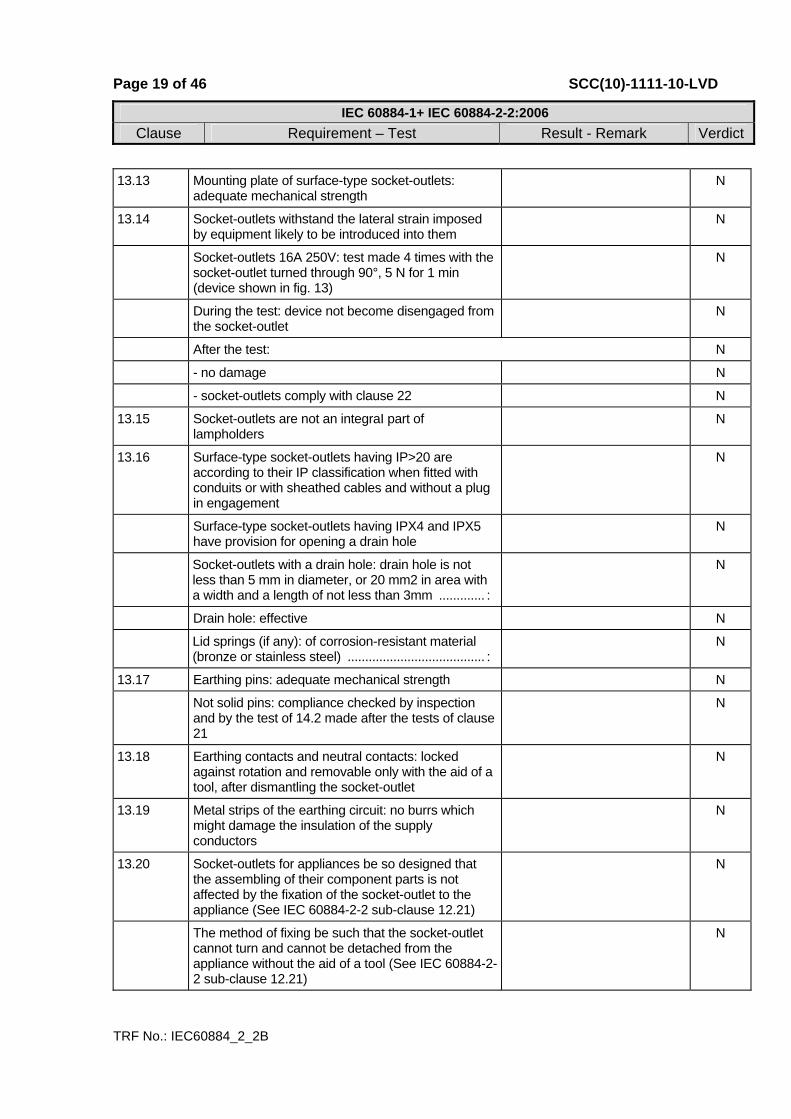
13.13 Mounting plate of surface-type socket-outlets: adequate mechanical strength
N
13.14 Socket-outlets withstand the lateral strain imposed by equipment likely to be introduced into them
N
Socket-outlets 16A 250V: test made 4 times with the socket-outlet turned through 90°, 5 N for 1 min (device shown in fig. 13)
N
During the test: device not become disengaged from the socket-outlet
N
After the test: N
- no damage N
- socket-outlets comply with clause 22 N
13.15 Socket-outlets are not an integraI part of lampholders
N
13.16 Surface-type socket-outlets having IP>20 are according to their IP classification when fitted with conduits or with sheathed cables and without a plug in engagement
N
Surface-type socket-outlets having IPX4 and IPX5 have provision for opening a drain hole
N
Socket-outlets with a drain hole: drain hole is not less than 5 mm in diameter, or 20 mm2 in area with a width and a length of not less than 3mm ............. :
N
Drain hole: effective N
Lid springs (if any): of corrosion-resistant material (bronze or stainless steel) ....................................... :
N
13.17 Earthing pins: adequate mechanical strength N
Not solid pins: compliance checked by inspection and by the test of 14.2 made after the tests of clause 21
N
13.18 Earthing contacts and neutral contacts: locked against rotation and removable only with the aid of a tool, after dismantling the socket-outlet
N
13.19 Metal strips of the earthing circuit: no burrs which might damage the insulation of the supply conductors
N
13.20 Socket-outlets for appliances be so designed that the assembling of their component parts is not affected by the fixation of the socket-outlet to the appliance (See IEC 60884-2-2 sub-clause 12.21)
N
The method of fixing be such that the socket-outlet cannot turn and cannot be detached from the appliance without the aid of a tool (See IEC 60884-2-2 sub-clause 12.21)
N
Page 20 of 46 SCC(10)-1111-10-LVD
IEC 60884-1+ IEC 60884-2-2:2006Clause Requirement – Test Result - Remark Verdict
TRF No.: IEC60884_2_2B
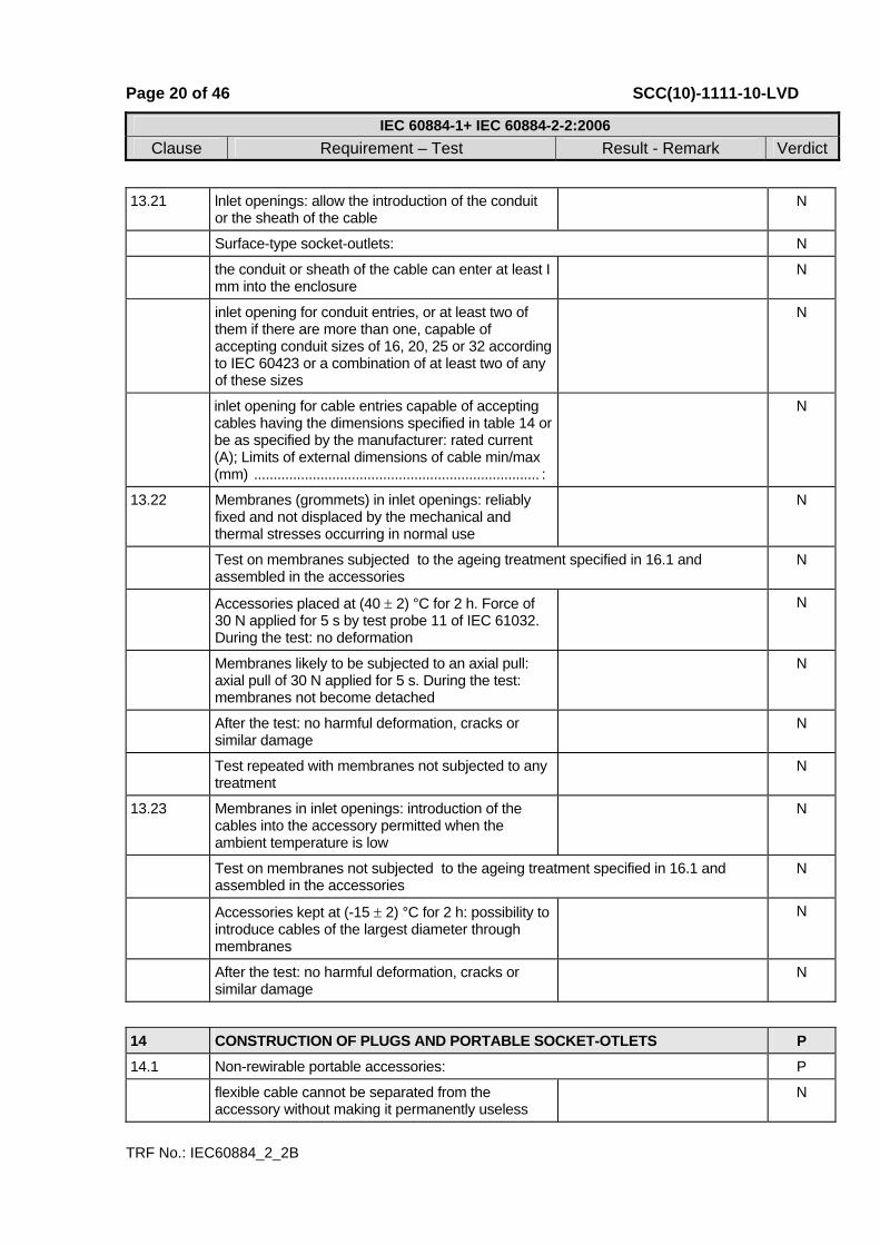
13.21 lnlet openings: allow the introduction of the conduit or the sheath of the cable
N
Surface-type socket-outlets: N
the conduit or sheath of the cable can enter at least I mm into the enclosure
N
inlet opening for conduit entries, or at least two of them if there are more than one, capable of accepting conduit sizes of 16, 20, 25 or 32 according to IEC 60423 or a combination of at least two of any of these sizes
N
inlet opening for cable entries capable of accepting cables having the dimensions specified in table 14 or be as specified by the manufacturer: rated current (A); Limits of external dimensions of cable min/max (mm) ......................................................................... :
N
13.22 Membranes (grommets) in inlet openings: reliably fixed and not displaced by the mechanical and thermal stresses occurring in normal use
N
Test on membranes subjected to the ageing treatment specified in 16.1 and assembled in the accessories
N
Accessories placed at (40 ± 2) °C for 2 h. Force of 30 N applied for 5 s by test probe 11 of IEC 61032. During the test: no deformation
N
Membranes likely to be subjected to an axial pull: axial pull of 30 N applied for 5 s. During the test: membranes not become detached
N
After the test: no harmful deformation, cracks or similar damage
N
Test repeated with membranes not subjected to any treatment
N
13.23 Membranes in inlet openings: introduction of the cables into the accessory permitted when the ambient temperature is low
N
Test on membranes not subjected to the ageing treatment specified in 16.1 and assembled in the accessories
N
Accessories kept at (-15 ± 2) °C for 2 h: possibility to introduce cables of the largest diameter through membranes
N
After the test: no harmful deformation, cracks or similar damage
N
14 CONSTRUCTION OF PLUGS AND PORTABLE SOCKET-OTLETS P 14.1 Non-rewirable portable accessories: P
flexible cable cannot be separated from the accessory without making it permanently useless
N

Page 21 of 46 SCC(10)-1111-10-LVD
IEC 60884-1+ IEC 60884-2-2:2006Clause Requirement – Test Result - Remark Verdict
TRF No.: IEC60884_2_2B
Accessory cannot be opened by hand or by using a generaI purpose tool, for example a screwdriver used as such
P
14.2 Pins of portable accessories: adequate mechanical strength
P
Test for pins not solid (made after clause 21): force of 100 N exerted on the pin, according to figure 14, for 1 min by means of a steel rod Ø 4,8 mm
P
During the application of the force: reduction of the dimension of the pin not exceed 0,15 mm
Pass muster Not exceed 0.15mm
P
After removal of the rod: dimensions of the pin not changed by more than 0,06 mm
0.01mm Pass muster
P
14.3 Pins of plugs: P
- locked against rotation P
- not removable without dismantling the plug P
- adequately fixed in the body of the plug when the plug is wired and assembled as in normal use
P
Earthing or neutral pins or contacts of plugs: not possible to arrange in an incorrect position
P
14.4 Earthing contacts and neutral contacts of portable socket-outlets: P
- locked against rotation N
- removable only with the aid of a tool, after dismantling the socket-outlet
Need the aid of a tool P
14.5 Socket-contact assemblies: sufficient resilience P
14.6 Pins and socket-contacts: resistant to corrosion and abrasion
P
14.7 Enclosures of rewirable portable accessories: completely enclose terminals and ends of flexible cable
N
Construction of rewirable accessories: N
- conductors can be properly connected N
- cores not pressed against each other N
- cores of live conductor not pressed against accessible metal parts
N
- core of earthing conductor not pressed against live parts
N
14.8 Rewirable portable accessories: terminal screws or nuts cannot become loose and fall out of position and establish an electrical connection between live parts and earthing terminal or metal parts
N
14.9 Rewirable portable accessories with earthing contact: ampIe space for slack of earthing (test)
N
Page 22 of 46 SCC(10)-1111-10-LVD
IEC 60884-1+ IEC 60884-2-2:2006Clause Requirement – Test Result - Remark Verdict
TRF No.: IEC60884_2_2B
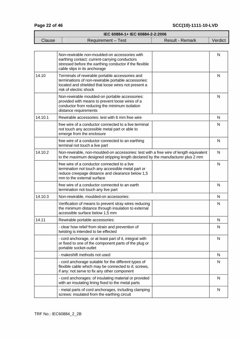
Non-rewirable non-moulded-on accessories with earthing contact: current-carrying conductors stressed before the earthing conductor if the flexible cable slips in its anchorage
N
14.10 Terminals of rewirable portable accessories and terminations of non-rewirable portable accessories: located and shielded that loose wires not present a risk of electric shock
N
Non-rewirable moulded-on portable accessories: provided with means to prevent loose wires of a conductor from reducing the minimum isolation distance requirements
N
14.10.1 Rewirable accessories: test with 6 mm free wire N
free wire of a conductor connected to a live terminal not touch any accessible metal part or able to emerge from the enclosure
N
free wire of a conductor connected to an earthing terminal not touch a live part
N
14.10.2 Non-rewirable, non-moulded-on accessories: test with a free wire of length equivalent to the maximum designed stripping length declared by the manufacturer plus 2 mm
N
free wire of a conductor connected to a live termination not touch any accessible metal part or reduce creepage distance and clearance below 1,5 mm to the external surface
N
free wire of a conductor connected to an earth termination not touch any live part
N
14.10.3 Non-rewirable, moulded-on accessories: N
Verification of means to prevent stray wires reducing the minimum distance through insulation to external accessible surface below 1,5 mm
N
14.11 Rewirable portable accessories: N
- clear how relief from strain and prevention of twisting is intended to be effected
N
- cord anchorage, or at Ieast part of it, integraI with or fixed to one of the component parts of the plug or portable socket-outlet
N
- makeshift methods not used N
- cord anchorage suitable for the different types of flexible cable which may be connected to it; screws, if any: not serve to fix any other component
N
- cord anchorages: of insulating material or provided with an insulating lining fixed to the metal parts
N
- metal parts of cord anchorages, including clamping screws: insulated from the earthing circuit
N
Page 23 of 46 SCC(10)-1111-10-LVD
IEC 60884-1+ IEC 60884-2-2:2006Clause Requirement – Test Result - Remark Verdict
TRF No.: IEC60884_2_2B
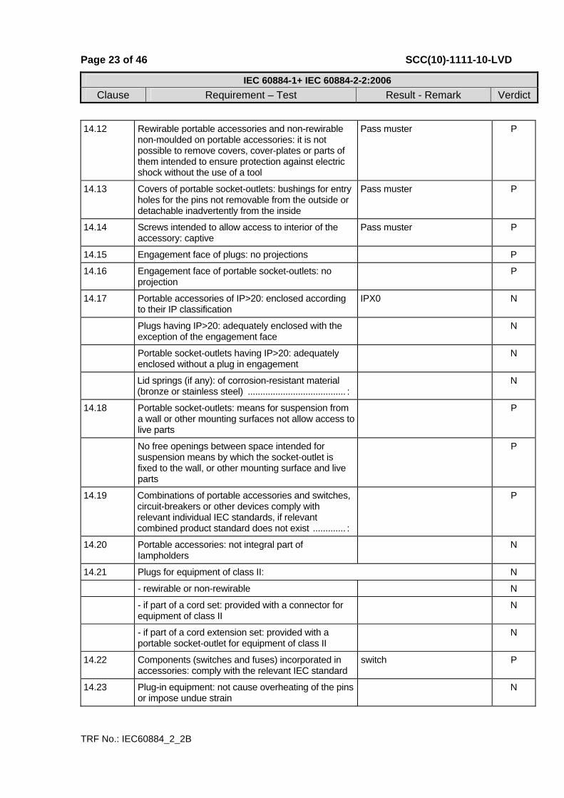
14.12 Rewirable portable accessories and non-rewirable non-moulded on portable accessories: it is not possible to remove covers, cover-plates or parts of them intended to ensure protection against electric shock without the use of a tool
Pass muster P
14.13 Covers of portable socket-outlets: bushings for entry holes for the pins not removable from the outside or detachable inadvertently from the inside
Pass muster P
14.14 Screws intended to allow access to interior of the accessory: captive
Pass muster P
14.15 Engagement face of plugs: no projections P
14.16 Engagement face of portable socket-outlets: no projection
P
14.17 Portable accessories of IP>20: enclosed according to their IP classification
IPX0 N
Plugs having IP>20: adequately enclosed with the exception of the engagement face
N
Portable socket-outlets having IP>20: adequately enclosed without a plug in engagement
N
Lid springs (if any): of corrosion-resistant material (bronze or stainless steel) ....................................... :
N
14.18 Portable socket-outlets: means for suspension from a wall or other mounting surfaces not allow access to live parts
P
No free openings between space intended for suspension means by which the socket-outlet is fixed to the wall, or other mounting surface and live parts
P
14.19 Combinations of portable accessories and switches, circuit-breakers or other devices comply with relevant individual IEC standards, if relevant combined product standard does not exist ............. :
P
14.20 Portable accessories: not integral part of Iampholders
N
14.21 Plugs for equipment of class II: N
- rewirable or non-rewirable N
- if part of a cord set: provided with a connector for equipment of class II
N
- if part of a cord extension set: provided with a portable socket-outlet for equipment of class II
N
14.22 Components (switches and fuses) incorporated in accessories: comply with the relevant IEC standard
switch P
14.23 Plug-in equipment: not cause overheating of the pins or impose undue strain
N

Page 24 of 46 SCC(10)-1111-10-LVD
IEC 60884-1+ IEC 60884-2-2:2006Clause Requirement – Test Result - Remark Verdict
TRF No.: IEC60884_2_2B
Plugs with rating above 16 A and 250 V: not integral part of other equipment
N
Tests for two-pole plugs, with or without earthing contact, with rating up to and including 16 A and 250 V (plug of equipment inserted into a fixed socket-outlet complying with this standard):
N
14.23.1 Socket-outlet connected to a supply voltage equal to 1,1 times the highest rated voltage of the equipment (V) ............................................................................. :
⎯
Temperature rise of the pins after 1 h not exceed 45 K (K) ......................................................................... :
N
14.23.2 Additional torque applied to the socket-outlet in order to maintain the engagement face in the vertical plane not exceed 0,25 Nm (Nm) ....................................... :
N
14.24 Plugs: can easily withdrawn by hand from the relevant socket-outlet
N
Gripping surfaces: so designed that the plug can be withdrawn without pull on the flexible cable
N
14.25 Membranes in inlet openings of portable accessory: meet the requirements of 13.22 and 13.23
N
15 INTERLOCKED SOCKET-OUTLETS N Socket-outlet interlocked with a switch: N
plug cannot be inserted into or completely withdrawn from the socket-outlet while the socket-contacts are live
N
socket-contacts cannot be made live until a plug is almost completely in engagement
N
16 RESISTANCE TO AGEING, PROTECTION PROVIDED BY ENCLOSURES, AND RESISTANCE TO HUMIDITY
P
16.1 Resistance to ageing P
Accessories are resistant to ageing P
Accessories subjected to a test in a heating cabinet at (70 ± 2) °C for seven days (168 h)
71°C, 168h P
After the tests, the specimens show: P
- no crack visible with normal or corrected vision without additional magnification
P
- no sticky or greasy material P
- no trace of cloth (forefinger pressed with 5 N) P
- no damage P
16.2 Protection provided by enclosures P
Page 25 of 46 SCC(10)-1111-10-LVD
IEC 60884-1+ IEC 60884-2-2:2006Clause Requirement – Test Result - Remark Verdict
TRF No.: IEC60884_2_2B
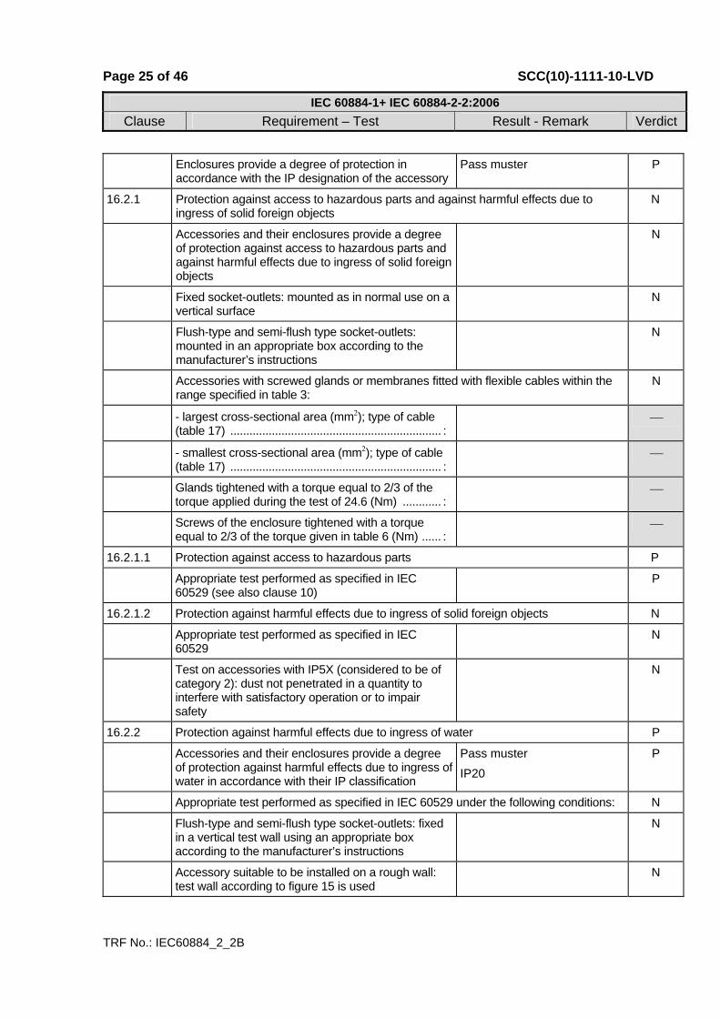
Enclosures provide a degree of protection in accordance with the IP designation of the accessory
Pass muster P
16.2.1 Protection against access to hazardous parts and against harmful effects due to ingress of solid foreign objects
N
Accessories and their enclosures provide a degree of protection against access to hazardous parts and against harmful effects due to ingress of solid foreign objects
N
Fixed socket-outlets: mounted as in normal use on a vertical surface
N
Flush-type and semi-flush type socket-outlets: mounted in an appropriate box according to the manufacturer’s instructions
N
Accessories with screwed glands or membranes fitted with flexible cables within the range specified in table 3:
N
- largest cross-sectional area (mm2); type of cable (table 17) .................................................................. :
⎯
- smallest cross-sectional area (mm2); type of cable (table 17) .................................................................. :
⎯
Glands tightened with a torque equal to 2/3 of the torque applied during the test of 24.6 (Nm) ............ :
⎯
Screws of the enclosure tightened with a torque equal to 2/3 of the torque given in table 6 (Nm) ...... :
⎯
16.2.1.1 Protection against access to hazardous parts P
Appropriate test performed as specified in IEC 60529 (see also clause 10)
P
16.2.1.2 Protection against harmful effects due to ingress of solid foreign objects N
Appropriate test performed as specified in IEC 60529
N
Test on accessories with IP5X (considered to be of category 2): dust not penetrated in a quantity to interfere with satisfactory operation or to impair safety
N
16.2.2 Protection against harmful effects due to ingress of water P
Accessories and their enclosures provide a degree of protection against harmful effects due to ingress of water in accordance with their IP classification
Pass muster IP20
P
Appropriate test performed as specified in IEC 60529 under the following conditions: N
Flush-type and semi-flush type socket-outlets: fixed in a vertical test wall using an appropriate box according to the manufacturer’s instructions
N
Accessory suitable to be installed on a rough wall: test wall according to figure 15 is used
N

Page 26 of 46 SCC(10)-1111-10-LVD
IEC 60884-1+ IEC 60884-2-2:2006Clause Requirement – Test Result - Remark Verdict
TRF No.: IEC60884_2_2B
Surface-type socket-outlets mounted as for normal use in a vertical position and fitted with cables (having conductors of the largest and smallest nominal cross-sectional area given in table 3) or conduits or both in accordance with the manufacturer’s instructions:
N
- largest cross-sectional area (mm2); type of cable (table 17) .................................................................. :
⎯
- smallest cross-sectional area (mm2); type of cable (table 17) .................................................................. :
⎯
Portable socket-outlets tested on a plain, horizontal surface in a position as in normal use and fitted with flexible cables (having conductors of the largest and smallest nominal cross-sectional area given in table 3) according to table 17:
N
- largest cross-sectional area (mm2); type of cable (table 17) .................................................................. :
⎯
- smallest cross-sectional area (mm2); type of cable (table 17) .................................................................. :
⎯
Screws of enclosure tightened with a torque equal to 2/3 of the torque given in table 6 (Nm) .................... :
⎯
Glands tightened with a torque equal to 2/3 of the torque applied during the test of 24.6 (Nm) ............ :
⎯
Accessory with drain holes opened during the test: any accumulation of water proved by inspection
N
Socket-outlets tested without a plug in engagement N
Plugs tested when in full engagement with: N
- a fixed socket-outlets N
- a portable socket-outlets N
of the same system and with the same degree of protection against harmful effects due to ingress of water
⎯
Specimens withstand an electric strength test specified in 17.2 which is started within 5 min of completion of the IP test
N
16.3 Resistance to humidity P
Accessories proof against humidity which may occur in normal use
P
Compliance checked by a humidity treatment carried out in a humidity cabinet containing air with relative humidity maintained between 91 % and 95 %
25℃, R.H.93% P
Specimens kept in the cabinet for: P
- two days (48 h) for accessories having IPX0 P
- seven days (168 h) for accessories having IP>X0 N
After this treatment the specimens show no damage P
Page 27 of 46 SCC(10)-1111-10-LVD
IEC 60884-1+ IEC 60884-2-2:2006Clause Requirement – Test Result - Remark Verdict
TRF No.: IEC60884_2_2B
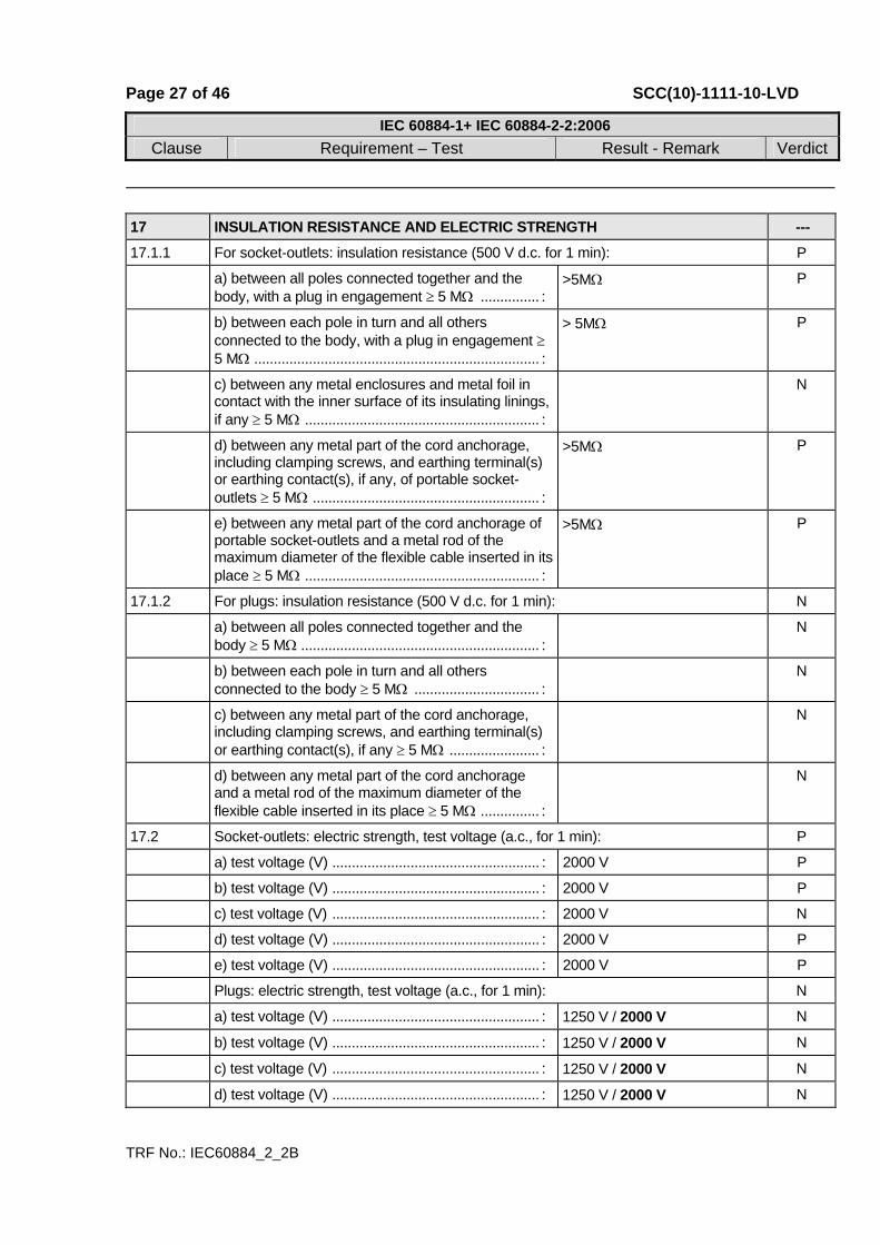
17 INSULATION RESISTANCE AND ELECTRIC STRENGTH --- 17.1.1 For socket-outlets: insulation resistance (500 V d.c. for 1 min): P
a) between all poles connected together and the body, with a plug in engagement ≥ 5 MΩ ............... :
>5MΩ P
b) between each pole in turn and all others connected to the body, with a plug in engagement ≥ 5 MΩ ......................................................................... :
> 5MΩ P
c) between any metal enclosures and metal foil in contact with the inner surface of its insulating linings, if any ≥ 5 MΩ ............................................................ :
N
d) between any metal part of the cord anchorage, including clamping screws, and earthing terminal(s) or earthing contact(s), if any, of portable socket-outlets ≥ 5 MΩ .......................................................... :
>5MΩ P
e) between any metal part of the cord anchorage of portable socket-outlets and a metal rod of the maximum diameter of the flexible cable inserted in its place ≥ 5 MΩ ............................................................ :
>5MΩ P
17.1.2 For plugs: insulation resistance (500 V d.c. for 1 min): N
a) between all poles connected together and the body ≥ 5 MΩ ............................................................. :
N
b) between each pole in turn and all others connected to the body ≥ 5 MΩ ................................ :
N
c) between any metal part of the cord anchorage, including clamping screws, and earthing terminal(s) or earthing contact(s), if any ≥ 5 MΩ ....................... :
N
d) between any metal part of the cord anchorage and a metal rod of the maximum diameter of the flexible cable inserted in its place ≥ 5 MΩ ............... :
N
17.2 Socket-outlets: electric strength, test voltage (a.c., for 1 min): P
a) test voltage (V) ..................................................... : 2000 V P
b) test voltage (V) ..................................................... : 2000 V P
c) test voltage (V) ..................................................... : 2000 V N
d) test voltage (V) ..................................................... : 2000 V P
e) test voltage (V) ..................................................... : 2000 V P
Plugs: electric strength, test voltage (a.c., for 1 min): N
a) test voltage (V) ..................................................... : 1250 V / 2000 V N
b) test voltage (V) ..................................................... : 1250 V / 2000 V N
c) test voltage (V) ..................................................... : 1250 V / 2000 V N
d) test voltage (V) ..................................................... : 1250 V / 2000 V N

Page 28 of 46 SCC(10)-1111-10-LVD
IEC 60884-1+ IEC 60884-2-2:2006Clause Requirement – Test Result - Remark Verdict
TRF No.: IEC60884_2_2B
During the test no flashover or breakdown P
18 OPERATION OF EARTHING CONTACTS P Earthing contacts provide adequate contact pressure
and not deteriorate in normal use P
Compliance checked by the tests of clauses 19 and 21
See the clause 19 and 21 P
Force exerted measured in side earthing contacts not less than 5 N (CEE 7 clause 18) ....................... :
P
19 TEMPERATURE RISE ⎯ Non-rewirable accessories tested as delivered: N
- type of flexible cable; number of conductors and nominal cross-sectional area (mm2) ....................... :
⎯
Rewirable accessories fitted with polyvinyl chloride insulated conductors having a nominal cross-sectional area as show in table 15:
P
- rated current of accessory ..................................... : ⎯
- nominal cross-sectional area (mm2) .................... : ⎯
- type of conductors ................................................ : ⎯
Terminal screws or nuts tightened with a torque equal to 2/3 of that specified in 12.2.8 (Nm) ......... :
0,27 ⎯
Socket-outlets tested using a test plug with brass pins having the minimum specified dimensions
P
Plugs tested using a fixed socket-outlet complying with the standard and having as near to average characteristics, but with minimum size of the earthing pin, if any
N
Test current as specified in table 20 passed for 1 h (A) ............................................................................. :
16A ⎯
Temperature rise of terminals not exceed 45 K (K) : P
Separate tests made passing the current through: P
- the neutral contact, if any, and the adjacent phase contact (K) ................................................................ :
22.1 P
- the earthing contact, if any, and the nearest phase contact (K) ................................................................ :
25.2 P
Temperature rise of external parts of insulating material not necessary to retain current-carrying parts and parts of the earthing circuit in position (K):
Enclosure plastic: 21.6 P
20 BREAKING CAPACITY P Accessories have adequate breaking capacity P

Page 29 of 46 SCC(10)-1111-10-LVD
IEC 60884-1+ IEC 60884-2-2:2006Clause Requirement – Test Result - Remark Verdict
TRF No.: IEC60884_2_2B
Compliance checked by testing: P
- socket-outlets P
- plugs with pins which are not solid N
Test conditions: P
- 100 strokes; rate of operation ............................... : 30 strokes per minute ⎯
- test voltage (1,1 Vn) .............................................. : 275V ⎯
- test current (1,25 In) (power factor 0,6) ................ : 20A ⎯
Multiple socket-outlets: test carried out on one socket-outlet of each type and current rating
N
During the test: no sustained arcing occur P
After the test: P
- specimens show no damage impairing their further use
P
- entry holes for the pins not show any damage which may impair the safety
P
21 NORMAL OPERATION P Accessories withstand without excessive wear or
other harmful effect, the mechanical, electrical and thermal stresses occurring in normal use
P
Compliance checked by testing: P
- socket-outlets P
- plugs with resilient earthing socket-contacts P
- plugs with pins which are not solid P
Test performed on: P
- complete shuttered socket-outlets N
- specimens prepared by the manufacturer without shutters (with current flowing). Number of strokes . :
N
- specimens with shutters (without current flowing) N
- complete shuttered socket-outlets with operations made by hand as in normal use
P
Test conditions: P
- 10000 strokes; rate of operation ........................... : 30 strokes per minute ⎯
- test voltage Vn (V) ................................................. : 275 ⎯
- test current (as specified in table 20) (A) (power factor 0,8) ................................................................. :
16A ⎯
Test current passed: P
- during each insertion and withdrawal of the plug (In ≤ 16A)
P

Page 30 of 46 SCC(10)-1111-10-LVD
IEC 60884-1+ IEC 60884-2-2:2006Clause Requirement – Test Result - Remark Verdict
TRF No.: IEC60884_2_2B
- during alternate insertion and withdrawal, the other insertion and withdrawal being made without current flowing (In > 16A)
N
Multiple socket-outlets: test carried out on one socket-outlet of each type and current rating
N
During the test: no sustained arcing occur P
After the test the specimens do not show: P
- wear impairing their further use P
- deterioration of enclosures, insulating lining or barriers
P
- damage to the entry holes for the pins, that might impair proper working
P
- loosening of electrical or mechanical connections P
- seepage of sealing compound P
Shuttered socket-outlets: the following gauges applied to the entry holes corresponding to live contacts do not touch live parts when they remain under the relevant forces:
N
Gauge of figure 9, applied with a force of 20 N, for approximately 5 s, successively in three directions
N
Steel gauge of figure 10, applied with a force of 1 N for approximately 5 s, in three directions
N
Temperature-rise test (requirements of clause 19): P
Test current as required for the normal operation test, given in table 20, passed for 1 h (A) ................ :
16A ⎯
Temperature rise of terminals not exceed 45 K (K) : P
Separate tests made passing the current through: P
- the neutral contact, if any, and the adjacent phase contact (K) ................................................................ :
31.2 P
- the earthing contact, if any, and the nearest phase contact (K) ................................................................ :
29.6 P
Socket-outlets: electric strength (sub-clause 17.2), test voltage (a.c., for 1 min): P
a) test voltage (V)...................................................... : 1500 V P
b) test voltage (V)...................................................... : 1500 V P
c) test voltage (V)...................................................... : 1500 V N
d) test voltage (V)...................................................... : 1500 V P
e) test voltage (V)...................................................... : 1500 V P
Plugs: electric strength (sub-clause 17.2), test voltage (a.c., for 1 min): N
a) test voltage (V)...................................................... : 1000 V / 1500 V N
b) test voltage (V)...................................................... : 1000 V / 1500 V N
c) test voltage (V)...................................................... : 1000 V / 1500 V N

Page 31 of 46 SCC(10)-1111-10-LVD
IEC 60884-1+ IEC 60884-2-2:2006Clause Requirement – Test Result - Remark Verdict
TRF No.: IEC60884_2_2B
d) test voltage (V)...................................................... : 1000 V / 1500 V N
During the test: no flashover or breakdown P
Fixed socket-outlets: test according to 13.1 N
Pins of plugs and portable socket-outlets: test according to 14.2
P
Force exerted measured in side earthing contacts not less than 60 % or 5 N (CEE 7 clause 18) ......... :
5N P
22 FORCE NECESSARY TO WITHDRAW THE PLUG P
Construction of accessory does allow the easy insertion and withdrawal of the plug, and prevent the plug from working out of the socket-outlet in normal use
P
Rated current (A) ..................................................... : 10 P
Number of poles ...................................................... : 3 P
22.1 Verification of the maximum withdrawal force (multi-pin gauge) N
- Maximum withdrawal force (N) ............................. : ⎯
The plug not remain in the socket-outlet N
22.2 Verification of the minimum withdrawal force (single-pin gauge) P
- Minimum withdrawal force (N) .............................. : 2N ⎯
The plug not fall from each individual contact-assembly within 30 s
P
23 FLEXIBLE CABLES AND THEIR CONNECTION P 23.1 Plugs and portable socket-outlets provided with a
cord anchorage such that the conductors are relieved from strain and that their covering is protected from abrasion
P
Sheath of flexible cable clamped within the cord anchorage
P
23.2 Pull and torque test P
Non-rewirable accessories: P
- rating of accessory ................................................ : ⎯
- type of flexible cable; number of conductors and nominal cross-sectional area (mm2) ........................ :
⎯
- pull (100 times) (N) ................................................ : 80N P
- torque (1 min) as specified in table 18 (Nm) ......... : 0,35 P
After the test: P
Displacement ≤ 2 mm .............................................. : 0,3 P
Page 32 of 46 SCC(10)-1111-10-LVD
IEC 60884-1+ IEC 60884-2-2:2006Clause Requirement – Test Result - Remark Verdict
TRF No.: IEC60884_2_2B
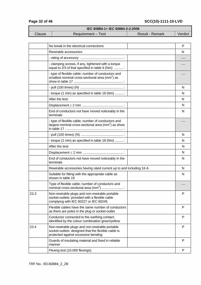
No break in the electrical connections P
Rewirable accessories: N
- rating of accessory ................................................ : ⎯
- clamping screws, if any, tightened with a torque equal to 2/3 of that specified in table 6 (Nm) .......... :
⎯
- type of flexible cable; number of conductors and smallest nominal cross-sectional area (mm2) as show in table 17 ....................................................... :
⎯
- pull (100 times) (N) ................................................ : N
- torque (1 min) as specified in table 18 (Nm) ......... : N
After the test: N
Displacement ≤ 2 mm .............................................. : N
End of conductors not have moved noticeably in the terminals
N
- type of flexible cable; number of conductors and largest nominal cross-sectional area (mm2) as show in table 17 ................................................................. :
⎯
- pull (100 times) (N) ............................................... : N
- torque (1 min) as specified in table 18 (Nm) ......... : N
After the test: N
Displacement ≤ 2 mm ............................................. : N
End of conductors not have moved noticeably in the terminals
N
Rewirable accessories having rated current up to and including 16 A: N
Suitable for fitting with the appropriate cable as shown in table 19
N
Type of flexible cable; number of conductors and nominal cross-sectional area (mm2) ........................ :
⎯
23.3 Non-rewirable plugs and non-rewirable portable socket-outlets: provided with a flexible cable complying with IEC 60227 or IEC 60245
P
Flexible cables have the same number of conductors as there are poles in the plug or socket-outlet
P
Conductor connected to the earthing contact: identified by the colour combination green/yellow
P
23.4 Non-rewirable plugs and non-rewirable portable socket-outlets: designed that the flexible cable is protected against excessive bending
P
Guards of insulating material and fixed in reliable manner
P
Flexing test (10.000 flexings): P
Page 33 of 46 SCC(10)-1111-10-LVD
IEC 60884-1+ IEC 60884-2-2:2006Clause Requirement – Test Result - Remark Verdict
TRF No.: IEC60884_2_2B
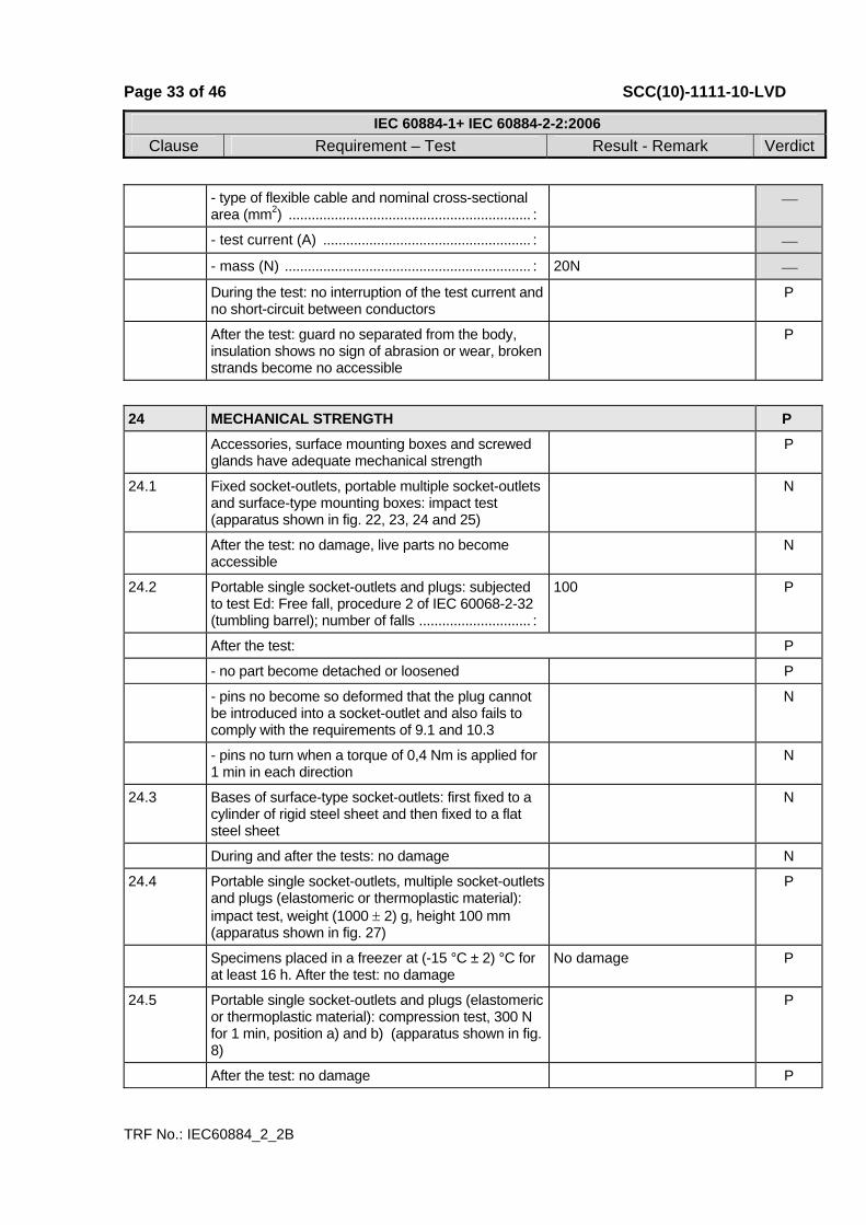
- type of flexible cable and nominal cross-sectional area (mm2) ............................................................... :
⎯
- test current (A) ...................................................... : ⎯
- mass (N) ................................................................ : 20N ⎯
During the test: no interruption of the test current and no short-circuit between conductors
P
After the test: guard no separated from the body, insulation shows no sign of abrasion or wear, broken strands become no accessible
P
24 MECHANICAL STRENGTH P Accessories, surface mounting boxes and screwed
glands have adequate mechanical strength P
24.1 Fixed socket-outlets, portable multiple socket-outlets and surface-type mounting boxes: impact test (apparatus shown in fig. 22, 23, 24 and 25)
N
After the test: no damage, live parts no become accessible
N
24.2 Portable single socket-outlets and plugs: subjected to test Ed: Free fall, procedure 2 of IEC 60068-2-32 (tumbling barrel); number of falls ............................. :
100 P
After the test: P
- no part become detached or loosened P
- pins no become so deformed that the plug cannot be introduced into a socket-outlet and also fails to comply with the requirements of 9.1 and 10.3
N
- pins no turn when a torque of 0,4 Nm is applied for 1 min in each direction
N
24.3 Bases of surface-type socket-outlets: first fixed to a cylinder of rigid steel sheet and then fixed to a flat steel sheet
N
During and after the tests: no damage N
24.4 Portable single socket-outlets, multiple socket-outlets and plugs (elastomeric or thermoplastic material): impact test, weight (1000 ± 2) g, height 100 mm (apparatus shown in fig. 27)
P
Specimens placed in a freezer at (-15 °C ± 2) °C for at least 16 h. After the test: no damage
No damage P
24.5 Portable single socket-outlets and plugs (elastomeric or thermoplastic material): compression test, 300 N for 1 min, position a) and b) (apparatus shown in fig. 8)
P
After the test: no damage P
Page 34 of 46 SCC(10)-1111-10-LVD
IEC 60884-1+ IEC 60884-2-2:2006Clause Requirement – Test Result - Remark Verdict
TRF No.: IEC60884_2_2B
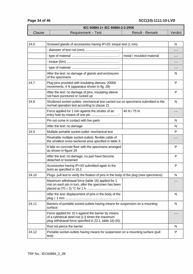
24.6 Screwed glands of accessories having IP>20: torque test (1 min) N
- diameter of test rod (mm) ...................................... : ⎯
- type of material ...................................................... : metal / moulded material ⎯
- torque (Nm) ............................................................ : ⎯
- type of material ...................................................... : ⎯
After the test: no damage of glands and enclosures of the specimens
N
24.7 Plug pins provided with insulating sleeves: 20000 movements, 4 N (apparatus shown in fig. 28)
P
After the test: no damage of pins, insulating sleeve not have punctured or rucked up
P
24.8 Shuttered socket-outlets: mechanical test carried out on specimens submitted to the normal operation test according to clause 21
N
Force applied for 1 min against the shutter of an entry hole by means of one pin ............................... :
40 N / 75 N ⎯
Pin not come in contact with live parts N
After the test: no damage N
24.9 Multiple portable socket-outlet: mechanical test P
Rewirable multiple socket-outlets: flexible cable of the smallest cross-sectional area specified in table 3:
⎯
8 falls on concrete floor with the specimens arranged as shown in figure 29
P
After the test: no damage, no part have become detached or loosened
P
Accessories having IP>X0 submitted again to the tests as specified in 16.2
P
24.10 Plugs: pull test to verify the fixation of pins in the body of the plug (new specimens) N
Maximum withdrawal force (table 16) applied for 1 min on each pin in turn, after the specimen has been placed at (70 ± 2) °C for 1 h .................................... :
⎯
After the test: displacement of pins in the body of the plug ≤ 1 mm ............................................................. :
N
24.11 Barriers of portable socket-outlets having means for suspension on a mounting surface:
N
Force applied for 10 s against the barrier by means of a cylindrical steel rod (1,5 times the maximum plug withdrawal force specified in 22.1, table 16) (N):
⎯
Rod not pierce the barrier N
24.12 Portable socket-outlets having means for suspension on a mounting surface (pull test):
P
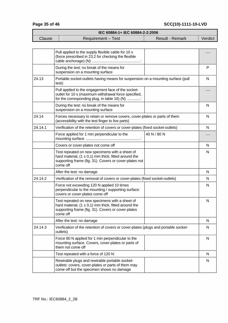
Page 35 of 46 SCC(10)-1111-10-LVD
IEC 60884-1+ IEC 60884-2-2:2006Clause Requirement – Test Result - Remark Verdict
TRF No.: IEC60884_2_2B
Pull applied to the supply flexible cable for 10 s (force prescribed in 23.2 for checking the flexible cable anchorage) (N) ............................................... :
⎯
During the test: no break of the means for suspension on a mounting surface
P
24.13 Portable socket-outlets having means for suspension on a mounting surface (pull test):
N
Pull applied to the engagement face of the socket-outlet for 10 s (maximum withdrawal force specified, for the corresponding plug, in table 16) (N) ............ :
⎯
During the test: no break of the means for suspension on a mounting surface
N
24.14 Forces necessary to retain or remove covers, cover-plates or parts of them (accessibility with the test finger to live parts)
N
24.14.1 Verification of the retention of covers or cover-plates (fixed socket-outlets) N
Force applied for 1 min perpendicular to the mounting surface ..................................................... :
40 N / 80 N ⎯
Covers or cover-plates not come off N
Test repeated on new specimens with a sheet of hard material, (1 ± 0,1) mm thick, fitted around the supporting frame (fig. 31). Covers or cover-plates not come off
N
After the test: no damage N
24.14.2 Verification of the removal of covers or cover-plates (fixed socket-outlets) N
Force not exceeding 120 N applied 10 times perpendicular to the mounting / supporting surface: covers or cover-plates come off
N
Test repeated on new specimens with a sheet of hard material, (1 ± 0,1) mm thick, fitted around the supporting frame (fig. 31). Covers or cover-plates come off
N
After the test: no damage N
24.14.3 Verification of the retention of covers or cover-plates (plugs and portable socket-outlets)
N
Force 80 N applied for 1 min perpendicular to the mounting surface. Covers, cover-plates or parts of them not come off
N
Test repeated with a force of 120 N: N
Rewirable plugs and rewirable portable socket-outlets: covers, cover-plates or parts of them may come off but the specimen shows no damage
N
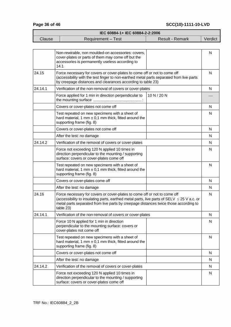
Page 36 of 46 SCC(10)-1111-10-LVD
IEC 60884-1+ IEC 60884-2-2:2006Clause Requirement – Test Result - Remark Verdict
TRF No.: IEC60884_2_2B
Non-rewirable, non moulded-on accessories: covers, cover-plates or parts of them may come off but the accessories is permanently useless according to 14.1
N
24.15 Force necessary for covers or cover-plates to come off or not to come off (accessibility with the test finger to non-earthed metal parts separated from live parts by creepage distances and clearances according to table 23)
N
24.14.1 Verification of the non-removal of covers or cover-plates N
Force applied for 1 min in direction perpendicular to the mounting surface ............................................... :
10 N / 20 N ⎯
Covers or cover-plates not come off N
Test repeated on new specimens with a sheet of hard material, 1 mm ± 0,1 mm thick, fitted around the supporting frame (fig. 8)
N
Covers or cover-plates not come off N
After the test: no damage N
24.14.2 Verification of the removal of covers or cover-plates N
Force not exceeding 120 N applied 10 times in direction perpendicular to the mounting / supporting surface: covers or cover-plates come off
N
Test repeated on new specimens with a sheet of hard material, 1 mm ± 0,1 mm thick, fitted around the supporting frame (fig. 8)
N
Covers or cover-plates come off N
After the test: no damage N
24.16 Force necessary for covers or cover-plates to come off or not to come off (accessibility to insulating parts, earthed metal parts, live parts of SELV ≤ 25 V a.c. or metal parts separated from live parts by creepage distances twice those according to table 23)
N
24.14.1 Verification of the non-removal of covers or cover-plates N
Force 10 N applied for 1 min in direction perpendicular to the mounting surface: covers or cover-plates not come off
N
Test repeated on new specimens with a sheet of hard material, 1 mm ± 0,1 mm thick, fitted around the supporting frame (fig. 8)
N
Covers or cover-plates not come off N
After the test: no damage N
24.14.2 Verification of the removal of covers or cover-plates N
Force not exceeding 120 N applied 10 times in direction perpendicular to the mounting / supporting surface: covers or cover-plates come off
N
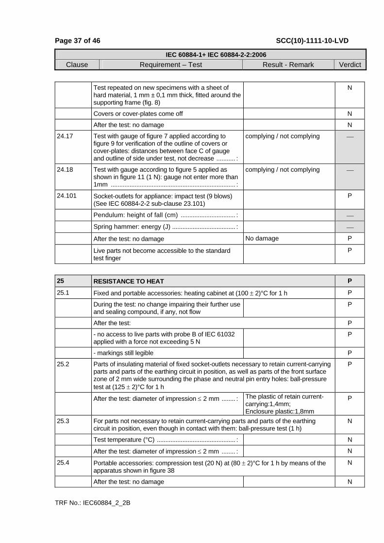
Page 37 of 46 SCC(10)-1111-10-LVD
IEC 60884-1+ IEC 60884-2-2:2006Clause Requirement – Test Result - Remark Verdict
TRF No.: IEC60884_2_2B
Test repeated on new specimens with a sheet of hard material, 1 mm ± 0,1 mm thick, fitted around the supporting frame (fig. 8)
N
Covers or cover-plates come off N
After the test: no damage N
24.17 Test with gauge of figure 7 applied according to figure 9 for verification of the outline of covers or cover-plates: distances between face C of gauge and outline of side under test, not decrease ........... :
complying / not complying ⎯
24.18 Test with gauge according to figure 5 applied as shown in figure 11 (1 N): gauge not enter more than 1mm ......................................................................... :
complying / not complying ⎯
24.101 Socket-outlets for appliance: impact test (9 blows) (See IEC 60884-2-2 sub-clause 23.101)
P
Pendulum: height of fall (cm) ................................ : ⎯
Spring hammer: energy (J) ..................................... : ⎯
After the test: no damage No damage P
Live parts not become accessible to the standard test finger
P
25 RESISTANCE TO HEAT P
25.1 Fixed and portable accessories: heating cabinet at (100 ± 2)°C for 1 h P
During the test: no change impairing their further use and sealing compound, if any, not flow
P
After the test: P
- no access to live parts with probe B of IEC 61032 applied with a force not exceeding 5 N
P
- markings still legible P
25.2 Parts of insulating material of fixed socket-outlets necessary to retain current-carrying parts and parts of the earthing circuit in position, as well as parts of the front surface zone of 2 mm wide surrounding the phase and neutral pin entry holes: ball-pressure test at (125 ± 2)°C for 1 h
P
After the test: diameter of impression ≤ 2 mm ........ : The plastic of retain current-carrying:1,4mm; Enclosure plastic:1,8mm
P
25.3 For parts not necessary to retain current-carrying parts and parts of the earthing circuit in position, even though in contact with them: ball-pressure test (1 h)
N
Test temperature (°C) .............................................. : N
After the test: diameter of impression ≤ 2 mm ........ : N
25.4 Portable accessories: compression test (20 N) at (80 ± 2)°C for 1 h by means of the apparatus shown in figure 38
N
After the test: no damage N

Page 38 of 46 SCC(10)-1111-10-LVD
IEC 60884-1+ IEC 60884-2-2:2006Clause Requirement – Test Result - Remark Verdict
TRF No.: IEC60884_2_2B
26 SCREWS, CURRENT-CARRYING PARTS AND CONNECTIONS P 26.1 Connections withstand mechanical stresses P
Thread-forming or thread-cutting screws used only if supplied together with the piece in which they are intended to be inserted
N
Thread-cutting screws intended to be used during installation: captive
N
Screws and nuts which transmit contact pressure: in engagement with a metal thread
P
Test: P
- 10 times for screws in engagement with a thread of insulating material and for screws of insulating material
P
- 5 times for all other cases N
- terminals: screw diameter (mm); torque (Nm); times ⎯
- earthing terminals: screw diameter (mm); torque (Nm); times ............................................................... :
2,5mm, 0,4 Nm, 10times ⎯
- assembly screws: screw diameter (mm); torque (Nm); times ............................................................... :
2,8mm, 0,4 Nm, 10times ⎯
- cord anchorage: screw diameter (mm); torque (Nm); times ............................................................... :
3,0mm, 0,5 Nm, 10times ⎯
- other screws or nuts: diameter (mm); torque (Nm); times ......................................................................... :
⎯
During the test: no damage impairing the further use of the screwed connectons
P
26.2 Screws in engagement with a thread of insulating material: correct introduction into the screw hole or nut ensured
P
26.3 Contact pressure: not transmitted through insulating material other than ceramic, pure mica or other material no less suitable unless there is sufficient resiliency in metallic parts
P
Connections made by insulation piercing of tinsel cord reliable
P
26.4 Screws and rivets locked against loosening and/or turning
P
26.5 Current-carrying parts (including earthing terminals) have mechanical strength, electrical conductivity and resistance to corrosion adequate:
P
- copper P
- alloy with at least 58 % copper for parts made from cold-rolled sheet or with at least 50 % copper for other parts
N

Page 39 of 46 SCC(10)-1111-10-LVD
IEC 60884-1+ IEC 60884-2-2:2006Clause Requirement – Test Result - Remark Verdict
TRF No.: IEC60884_2_2B
- stainless steel with at least 13 % chromium and not more than 0,09 % carbon
N
- steel with electroplated coating of zinc (ISO 2081), with thickness of at least: P
5 µm, service condition ISO no. 1 (IPX0) P
12 µm, service condition ISO no. 2, (IPX4) N
25 µm, service condition ISO no. 3, (IPX5) N
- steel with electroplated coating of nickel and chromium (ISO 1456), with thickness of at least:
P
20 µm, service condition ISO no. 2, (IPX0) P
30 µm, service condition ISO no. 3, (IPX4) N
40 µm, service condition ISO no. 4, (IPX5) N
- steel with electroplated coating of tin (ISO 2093), with thickness of at least: N
12 µm, service condition ISO no. 2, (IPX0) N
20 µm, service condition ISO no. 3, (IPX4) N
30 µm, service condition ISO no. 4, (IPX5) N
Current-carrying parts subjected to mechanical wear: not of steel with electroplated coating
N
Metals having a great difference of electrochemical potential: not used in contact with each other
N
26.6 Contacts subjected to a sliding action: of metal resistant to corrosion
P
26.7 Thread-forming screws and thread-cutting screws not used for the connection of current-carrying parts
N
Thread-forming screws and thread-cutting screws used to provide earthing connection: not necessary to disturb the connection and at least two screws are used for each connection
N
27 CREEPAGE DISTANCES, CLEARANCES AND DISTANCES THROUGH SEALING COMPOUND
P
27.1 Creepage distances, clearances and distances through sealing compound no less than the values shown in table 23
P
Creepage distances (cr): P
1) between live parts of different polarity ≥ 4(3) mm: >4mm P
2) between live parts and: P
- accessible surface of parts of insulating material ≥ 3 mm ..................................................................... :
>3mm P
- earthed metal parts including parts of earthing circuit ≥ 3 mm ........................................................... :
>3mm P

Page 40 of 46 SCC(10)-1111-10-LVD
IEC 60884-1+ IEC 60884-2-2:2006Clause Requirement – Test Result - Remark Verdict
TRF No.: IEC60884_2_2B
- metal frames supporting the base of flush-type socket-outlets ≥ 3 mm .............................................. :
N
- screws or devices for fixing bases, covers or cover-plates of fixed socket-outlets ≥ 3 mm ...................... :
>3mm P
- external assembly screws, other than screws which are on the engagement face of plugs and are isolated from the earthing circuit ≥ 3 mm ................ :
>3mm P
3) between pins of plugs and metal parts connected to them, when fully engaged, and a socket-outlet of the same system having accessible unearthed metal parts ≥ 6(4,5) mm ..................................................... :
N
4) between the accessible unearthed metal parts of a socket-outlet and a fully engaged plug of the same system having pins and metal parts connected to them ≥ 6(4,5) mm .................................................... :
N
5) between live parts of a socket-outlet (without a plug) or of a plug and their accessible unearthed or functional earthed metal parts ≥ 6(4,5) mm ............ :
N
6) between live parts of different polarity ≥ 3 mm ... : >3 mm P
7) between live parts and: P
- accessible surface of parts of insulating material ≥ 3 mm ..................................................................... :
>3 mm P
- earthed metal parts not mentioned under 8 and 9 including parts of earthing circuit ≥ 3 mm ............... :
>3 mm P
- metal frames supporting the base of flush-type socket-outlets ≥ 3 mm .............................................. :
N
- screws or devices for fixing bases, covers or cover-plates of fixed socket-outlets ≥ 3 mm ...................... :
>3 mm P
- external assembly screws, other than screws which are on the engagement face of plugs and are isolated from the earthing circuit ≥ 3 mm ................ :
>3 mm P
8) between live parts and: P
- exclusively earthed metal boxes ≥ 3 mm .............. : >3 mm P
- unearthed metal boxes, without insulating lining ≥ 4,5 mm .................................................................. :
N
- accessible unearthed or functional earthed metal parts of socket-outlets and plugs ≥ 6 mm ............... :
N
9) between live parts and the surfaces on which the base of a socket-outlet for surface mounting is mounted ≥ 6 mm....................................................... :
>6 mm P
10) between live parts and the bottom of any conductor recess, if any, in the base of a socket-outlet for surface mounting ≥ 3 mm.......................... :
>3 mm P
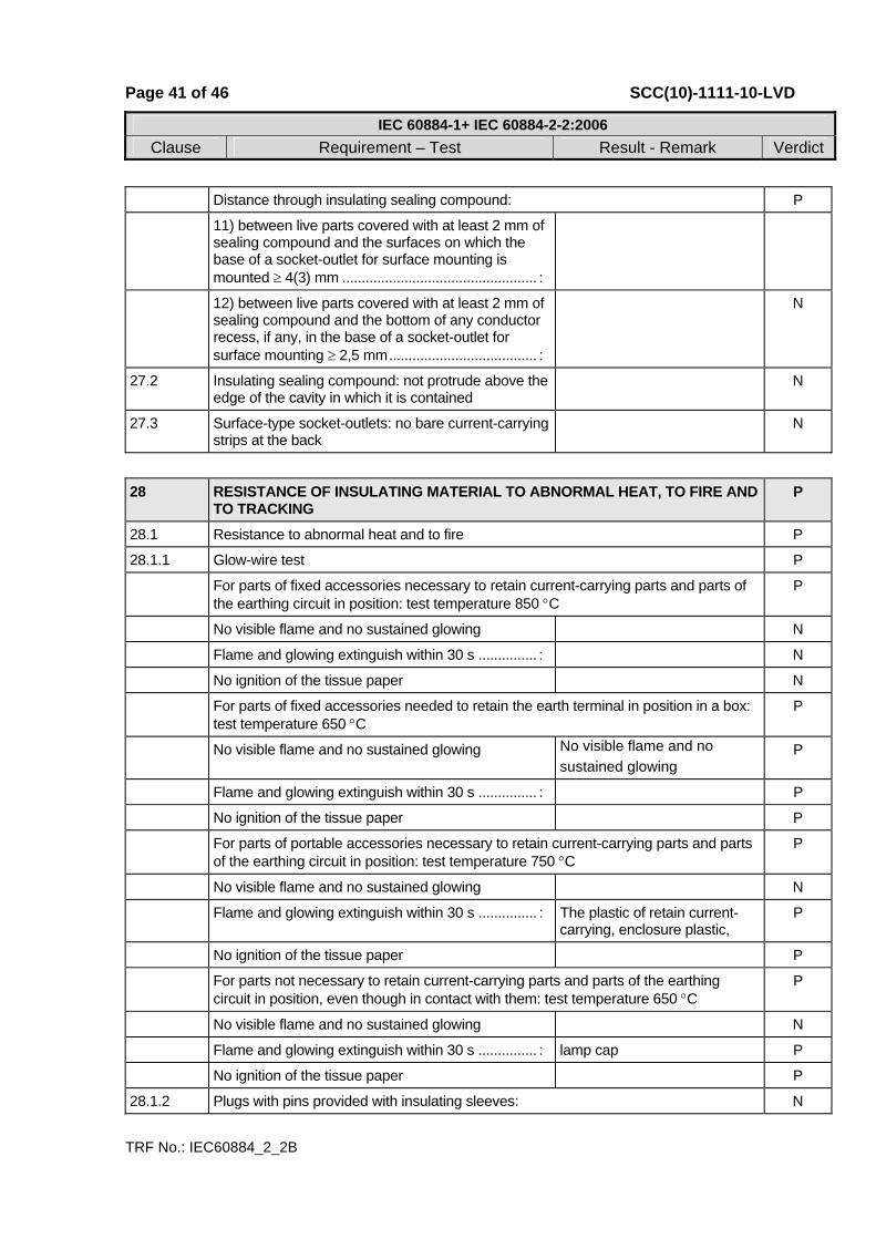
Page 41 of 46 SCC(10)-1111-10-LVD
IEC 60884-1+ IEC 60884-2-2:2006Clause Requirement – Test Result - Remark Verdict
TRF No.: IEC60884_2_2B
Distance through insulating sealing compound: P
11) between live parts covered with at least 2 mm of sealing compound and the surfaces on which the base of a socket-outlet for surface mounting is mounted ≥ 4(3) mm .................................................. :
12) between live parts covered with at least 2 mm of sealing compound and the bottom of any conductor recess, if any, in the base of a socket-outlet for surface mounting ≥ 2,5 mm...................................... :
N
27.2 Insulating sealing compound: not protrude above the edge of the cavity in which it is contained
N
27.3 Surface-type socket-outlets: no bare current-carrying strips at the back
N
28 RESISTANCE OF INSULATING MATERIAL TO ABNORMAL HEAT, TO FIRE AND TO TRACKING
P
28.1 Resistance to abnormal heat and to fire P
28.1.1 Glow-wire test P
For parts of fixed accessories necessary to retain current-carrying parts and parts of the earthing circuit in position: test temperature 850 °C
P
No visible flame and no sustained glowing N
Flame and glowing extinguish within 30 s ............... : N
No ignition of the tissue paper N
For parts of fixed accessories needed to retain the earth terminal in position in a box: test temperature 650 °C
P
No visible flame and no sustained glowing No visible flame and no sustained glowing
P
Flame and glowing extinguish within 30 s ............... : P
No ignition of the tissue paper P
For parts of portable accessories necessary to retain current-carrying parts and parts of the earthing circuit in position: test temperature 750 °C
P
No visible flame and no sustained glowing N
Flame and glowing extinguish within 30 s ............... : The plastic of retain current-carrying, enclosure plastic,
P
No ignition of the tissue paper P
For parts not necessary to retain current-carrying parts and parts of the earthing circuit in position, even though in contact with them: test temperature 650 °C
P
No visible flame and no sustained glowing N
Flame and glowing extinguish within 30 s ............... : lamp cap P
No ignition of the tissue paper P
28.1.2 Plugs with pins provided with insulating sleeves: N
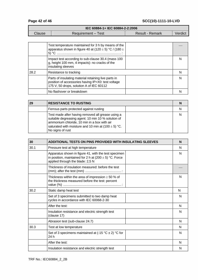
Page 42 of 46 SCC(10)-1111-10-LVD
IEC 60884-1+ IEC 60884-2-2:2006Clause Requirement – Test Result - Remark Verdict
TRF No.: IEC60884_2_2B
Test temperature maintained for 3 h by means of the apparatus shown in figure 40 at (120 ± 5) °C / (180 ± 5) °C ......................................................................... :
⎯
Impact test according to sub-clause 30.4 (mass 100 g, height 100 mm, 4 impacts): no cracks of the insulating sleeves
N
28.2 Resistance to tracking N
Parts of insulating material retaining live parts in position of accessories having IP>X0: test voltage 175 V, 50 drops, solution A of IEC 60112
N
No flashover or breakdown N
29 RESISTANCE TO RUSTING N Ferrous parts protected against rusting N
Test made after having removed all grease using a suitable degreasing agent: 10 min 10 % solution of ammonium chloride, 10 min in a box with air saturated with moisture and 10 min at (100 ± 5) °C. No signs of rust
N
30 ADDITIONAL TESTS ON PINS PROVIDED WITH INSULATING SLEEVES N 30.1 Pressure test at high temperature N
Apparatus shown in figure 41, with the test specimen in position, maintained for 2 h at (200 ± 5) °C. Force applied through the blade: 2,5 N
N
Thickness of insulation measured: before the test (mm); after the test (mm) ......................................... :
⎯
Thickness within the area of impression ≥ 50 % of the thickness measured before the test: percent value (%) .................................................................. :
N
30.2 Static damp heat test N
Set of 3 specimens submitted to two damp heat cycles in accordance with IEC 60068-2-30
N
After the test: N
Insulation resistance and electric strength test (clause 17)
N
Abrasion test (sub-clause 24.7) N
30.3 Test at low temperature N
Set of 3 specimens maintained at (-15 °C ± 2) °C for 24 h
N
After the test: N
Insulation resistance and electric strength test N

Page 43 of 46 SCC(10)-1111-10-LVD
IEC 60884-1+ IEC 60884-2-2:2006Clause Requirement – Test Result - Remark Verdict
TRF No.: IEC60884_2_2B
(clause 17)
Abrasion test (sub-clause 24.7) N
30.4 Impact test at low temperature N
Specimens maintained at (-15 °C ± 2) °C for 24 h subjected to 4 impacts (mass 100 g, height 100 mm) by means of the apparatus shown in figure 42 rotating the specimen through 90° between impacts
N
After the test: no crack of the insulating sleeves N

Page 44 of 46 SCC(10)-1111-10-LVD
TRF No.: IEC60884_2_2B
Photos of the sample
Picture 1
Picture 2
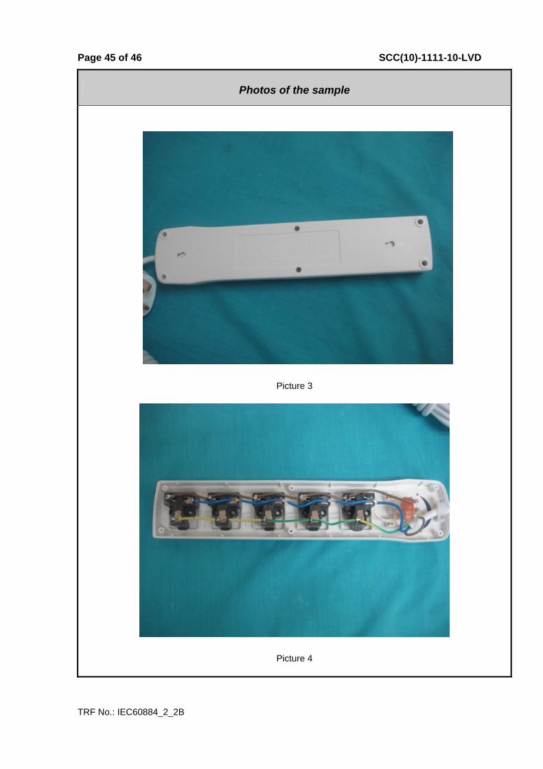
Page 45 of 46 SCC(10)-1111-10-LVD
TRF No.: IEC60884_2_2B
Photos of the sample
Picture 3
Picture 4
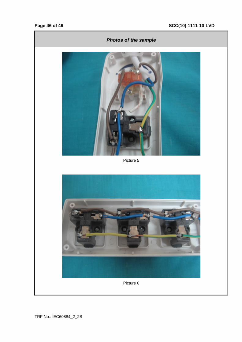
Page 46 of 46 SCC(10)-1111-10-LVD
TRF No.: IEC60884_2_2B
Photos of the sample
Picture 5
Picture 6

TRF No.: IEC60884_2_2B
Notice
1. This test report shall be invalidation without the cachet of the
testing laboratory.
2. This copied report shall be invalidation without sealed the
cachet of the testing laboratory.
3. This report shall be invalidation without tester signature,
reviewer signature and approver signature.
4. This altered report shall be invalidation.
5. Client shall put forward demurrer within 15days after received
report. The testing laboratory shall refuse disposal if exceeded
the time limit.
6. The test results presented in this report relate only to the object
tested.
Tel:028-84872600
Fax:028-84874181
Post code:610100
Add:No.45 Wenming Dong Road Longquanyi District, Chengdu,
Sichuan, China