test requirements and conceptual design for a potassium
TRANSCRIPT

ORNL/TM-2005/226
Test Requirements and Conceptual Design for a Potassium Test Loop to
Support an Advanced Potassium Rankine Cycle Power Conversion System
G. L. Yoder, Jr. R. W. Murphy C. B. Oland
J. J. Carbajo Oak Ridge National Laboratory
G. M. O’Connor Pratt and Whitney Rocketdyne
M. N. Nikitkin Swales Aerospace

DOCUMENT AVAILABILITY Reports produced after January 1, 1996, are generally available free via the U.S. Department of Energy (DOE) Information Bridge:
Web site: http://www.osti.gov/bridge Reports produced before January 1, 1996, may be purchased by members of the public from the following source:
National Technical Information Service 5285 Port Royal Road Springfield, VA 22161 Telephone: 703-605-6000 (1-800-553-6847) TDD: 703-487-4639 Fax: 703-605-6900 E-mail: [email protected] Web site: http://www.ntis.gov/support/ordernowabout.htm
Reports are available to DOE employees, DOE contractors, Energy Technology Data Exchange (ETDE) representatives, and International Nuclear Information System (INIS) representatives from the following source:
Office of Scientific and Technical Information P.O. Box 62 Oak Ridge, TN 37831 Telephone: 865-576-8401 Fax: 865-576-5728 E-mail: [email protected] Web site: http://www.osti.gov/contact.html
This report was prepared as an account of work sponsored by an agency of the United States Government. Neither the United States Government nor any agency thereof, nor any of their employees, makes any warranty, express or implied, or assumes any legal liability or responsibility for the accuracy, completeness, or usefulness of any information, apparatus, product, or process disclosed, or represents that its use would not infringe privately owned rights. Reference herein to any specific commercial product, process, or service by trade name, trademark, manufacturer, or otherwise, does not necessarily constitute or imply its endorsement, recommendation, or favoring by the United States Government or any agency thereof. The views and opinions of authors expressed herein do not necessarily state or reflect those of the United States Government or any agency thereof.
ORNL/TM-2005/226
TEST REQUIREMENTS AND CONCEPTUAL DESIGN FOR A POTASSIUM TEST LOOP TO SUPPORT AN ADVANCED
POTASSIUM RANKINE CYCLE POWER CONVERSION SYSTEM
G. L. Yoder, Jr. R. W. Murphy
C. B. Oland J. J. Carbajo
Oak Ridge National Laboratory
G. M. O’Connor
Pratt and Whitney Rocketdyne
M. N. Nikitkin
Swales Aerospace
September 30, 2005
Prepared for the National Aeronautics and Space Administration
Technology Development Program for an Advanced Potassium Rankine Power Conversion System Compatible with Several Space Reactor Designs
Prepared by the
OAK RIDGE NATIONAL LABORATORY Oak Ridge, Tennessee 37831
managed by UT-BATTELLE, LLC
for the U.S. DEPARTMENT OF ENERGY
under contract DE-AC05-00OR22725

ii

iii
CONTENTS
Page ABSTRACT ................................................................................................................................. 1-1 1. INTRODUCTION ................................................................................................................. 1-1
1.1 TESTING PROGRAM ................................................................................................ 1-2 1.2 SCOPE AND OBJECTIVE ......................................................................................... 1-2 1.3 TEST CONFIGURATIONS ........................................................................................ 1-2 1.4 REFERENCES............................................................................................................. 1-7
2. TESTING CRITERIA ........................................................................................................... 2-1 2.1 BEARING AND SEAL TESTS................................................................................... 2-1 2.2 TWO-PHASE FLOW TESTS...................................................................................... 2-5 2.3 HEAT PIPE TESTS..................................................................................................... 2-7 2.4 REFERENCES............................................................................................................. 2-9
3. TEST FACILITY DESIGN AND OPERATING REQUIREMENTS .................................. 3-1 3.1 STAINLESS STEEL PIPING SYSTEM..................................................................... 3-1 3.2 INSULATED SPLASH SHIELD .............................................................................. 3-10 3.3 VENTILATED ENCLOSURE .................................................................................. 3-11 3.4 POTASSIUM STORAGE AND HANDLING REQUIREMENTS .......................... 3-15 3.5 EX-LOOP POTASSIUM PURIFICATION SYSTEM.............................................. 3-18 3.6 EX-LOOP CLEAN-UP SYSTEM ............................................................................. 3-19 3.7 REFERENCES........................................................................................................... 3-19
4. SYSTEM OPERATIONS...................................................................................................... 4-1 4.1 NORMAL OPERATIONS .......................................................................................... 4-1 4.2 ABNORMAL OPERATING CONDITIONS.............................................................. 4-7 4.3 DECOMMISSIONING.............................................................................................. 4-10 4.4 REFERENCES........................................................................................................... 4-10
5. ENVIRONMENTAL, SAFETY, AND HEALTH REQUIREMENTS ................................ 5-1 5.1 STANDARDS BASED MANAGEMENT SYSTEM ................................................. 5-1 5.2 ISMS IMPLEMENTATION........................................................................................ 5-6 5.3 COMPRESSED-GAS CYLINDER STORAGE........................................................ 5-10 5.4 EMERGENCY RESPONSE...................................................................................... 5-10 5.5 MATERIAL REUSE AND HAZARDOUS WASTE DISPOSAL ........................... 5-10 5.6 REFERENCES........................................................................................................... 5-10
6. TEST FACILITY CONCEPTUAL DESIGN........................................................................ 6-1 6.1 BUILDING 5800, ROOM D111.................................................................................. 6-1 6.2 POTASSIUM TEST LOOP ......................................................................................... 6-3 6.3 SPLASH SHIELD AND GLOVE BOX.................................................................... 6-20 6.4 LIQUID-METAL TEST FACILITY ......................................................................... 6-22 6.5 POTASSIUM CLEANUP EQUIPMENT.................................................................. 6-25 6.6 REFERENCES........................................................................................................... 6-25
7. ENGINEERING ANALYSIS AND SUPPORTING CALCULATIONS............................. 7-1 7.1 PRESSURE DROP CALCULATIONS....................................................................... 7-1 7.2 GETTER CONSIDERATIONS................................................................................... 7-7 7.3 POTASSIUM-ARGON SEPARATION...................................................................... 7-9 7.4 TEMPERATURE OSCILLATIONS IN LIQUID-METAL BOILERS .................... 7-13 7.5 PIPING ANALYSIS AND DESIGN CONSIDERATIONS ..................................... 7-20 7.6 REFERENCES........................................................................................................... 7-21
8. SUMMARY AND CONCLUSIONS .................................................................................... 8-1 Appendix A. HYDROGEN GENERATION ANALYSIS..........................................................A-1 Appendix B. PIPING ANALYSIS AND DESIGN CONSIDERATIONS .................................B-1

iv

v
LIST OF FIGURES
Figure Page
1.1 Potassium test loop considerations........................................................................ 1-3 1.2 Potassium test loop schematic............................................................................... 1-4 1.3 Heat pipe schematic .............................................................................................. 1-6 1.4 Cross section of the proposed heat pipe ................................................................ 1-7 2.1 Baseline Rankine cycle schematic chosen for the 100-kW(e) system .................. 2-3 2.2 Flow schematic for the 115-kW(e) Rankine system ............................................. 2-4 3.1 DOT placard for Class 4.3 materials..................................................................... 3-15 3.2 14-kg metal DOT approved shipping container for transporting potassium......... 3-16 3.3 Large metal shipping container for transporting potassium.................................. 3-17 3.4 Preliminary conceptual design of the stainless steel piping system...................... 3-18 6.1 Aerial view of Oak Ridge National Laboratory main campus.............................. 6-2 6.2 Potassium test loop conceptual design .................................................................. 6-4 6.3 Potassium loop process instrumentation and control diagram .............................. 6-6 6.4 Sump tank conceptual design................................................................................ 6-7 6.5 Getter assembly conceptual design ....................................................................... 6-8 6.6 Potassium level detector and instrumentation schematic ...................................... 6-9 6.7 Wear and bearing test fixture conceptual design................................................... 6-13 6.8 Three-axis dovetail slide ....................................................................................... 6-16 6.9 Splash shield and glove box conceptual design .................................................... 6-21 6.10 Glove box conceptual design ................................................................................ 6-23 6.11 LMTF conceptual design ...................................................................................... 6-24 7.1 Proposed potassium test loop configuration.......................................................... 7-2 7.2 Calculated pressure drops for different pipe sizes with and without
the boiler ............................................................................................................... 7-4 7.3 Calculated liquid potassium velocities for different temperatures
and piping sizes. .................................................................................................... 7-4 7.4 Calculated pressure drops for single-phase (three temperatures)
and two-phase flow tests ....................................................................................... 7-5 7.5 Calculated pressure drops for two-phase boiling at 1000 K and single-phase
liquid at 700 K with the boiler (insert P/D = 2) and the condenser installed in the loop.............................................................................................................. 7-6
7.6 Sphere drag coefficient (potassium/argon systems).............................................. 7-10 7.7 Terminal velocity vs drop diameter (potassium sphere in argon) ......................... 7-11 7.8 Terminal velocity vs bubble diameter (argon sphere in potassium)...................... 7-12 7.9 DNB point for the lithium/potassium boiler with temperature gradients
on both sides of boiler wall ................................................................................... 7-14 7.10 Design fatigue curve for the CRBR boiler material at 399ºC ............................... 7-17 7.11 Fatigue assessment results..................................................................................... 7-19

vi

vii
LIST OF TABLES
Table Page 2.1 Criteria for bearing and seal tests.......................................................................... 2-1 2.2 Heat pipe measurement requirements ................................................................... 2-9 3.1 Condenser parameters for potassium test loop...................................................... 3-3 3.2 Bearing and seal test fixture requirements ............................................................ 3-4 3.3 Bearing and seal test vessel and test vessel drain system requirements................ 3-5 3.4 Minimum test loop instrumentation requirements ................................................ 3-9 3.5 LMTF design requirements................................................................................... 3-11 4.1 Pressure and temperature requirements for key operations................................... 4-1 4.2 Loss-of-potassium containment events ................................................................. 4-7 5.1 Core functions and guiding principles of ORNL’s Integrated Safety
Management System ............................................................................................. 5-2 5.2 Key Work Smart Standards potentially applicable to the Advanced
Potassium Rankine Power Conversion System..................................................... 5-3 5.3 Potential hazards for potassium and its reaction products .................................... 5-7 6.1 General loop fluid criteria ..................................................................................... 6-3 6.2 Valve alignment operating mode schedule ........................................................... 6-4 6.3 Boiler parameter options ....................................................................................... 6-11 7.1 Comparison of Space Reactor and CRBR boilers................................................. 7-15

viii

1-1
TEST REQUIREMENTS AND CONCEPTUAL DESIGN FOR A POTASSIUM TEST LOOP TO SUPPORT AN ADVANCED
POTASSIUM RANKINE CYCLE POWER CONVERSION SYSTEM
G. L. Yoder, Jr. C. B. Oland R. W. Murphy J. J. Carbajo
Oak Ridge National Laboratory
G. M. O’Connor
Pratt and Whitney Rocketdyne
M. N. Nikitkin
Swales Aerospace
ABSTRACT
Parameters for continuing the design and specification of an experimental potassium test loop are identified in this report. Design and construction of a potassium test loop is part of the Phase II effort of the project “Technology Development Program for an Advanced Potassium Rankine Power Conversion System.” This program is supported by the National Aeronautics and Space Administration. Design features for the potassium test loop and its instrumentation system, specific test articles, and engineered barriers for ensuring worker safety and protection of the environment are described along with safety and environmental protection requirements to be used during the design process. Information presented in the first portion of this report formed the basis to initiate the design phase of the program; however, the report is a living document that can be changed as necessary during the design process, reflecting modifications as additional design details are developed. Some portions of the report have parameters identified as “to be determined” (TBD), reflecting the early stage of the overall process. In cases where specific design values are presently unknown, the report attempts to document the quantities that remain to be defined in order to complete the design of the potassium test loop and supporting equipment.
1. INTRODUCTION
The National Aeronautics and Space Administration (NASA) has initiated a research program at the Oak Ridge National Laboratory (ORNL). This program entitled, Technology Development Program for an Advanced Potassium Rankine Power Conversion System Compatible with Several Space Reactor Designs, is part of the larger NASA development effort, the Prometheus Nuclear Systems and Technology Program, designed to develop a nuclear power source and conversion system for space exploration. It is designed to advance the technology state of the potassium Rankine power conversion system by first identifying the key elements necessary to prove the system’s readiness for use in space and then by selecting a few key technology areas to develop. The program has two phases. Phase I has been completed and the results are documented.1 It evaluated the performance of the potassium Rankine cycle for power

1-2
levels of 100 kW(e) and 250 kW(e), and outlined a Technology Development Plan for bringing the power conversion system to a technology readiness level (TRL) of six. Phase II of the program initiates this plan and includes development of an experimental potassium test loop designed to reestablish potassium testing capabilities that have been dormant for more than 30 years. 1.1 TESTING PROGRAM
The ORNL research program is an experimental effort for investigating thermal-hydraulic phenomena and material performance characteristics needed to develop an advanced potassium Rankine power conversion system. The main focus of the program involves construction and operation of a closed-loop piping system capable of circulating potassium under both single-phase and two-phase flow conditions. Single-phase testing focuses on bearing material wear behavior and heat pipe testing. During this testing, potassium circulates through the test loop at temperatures, pressures, and flow rates required to produce the needed test data. The loop design is such that two-phase flow tests can be performed by realigning the valves in the test loop and controlling the potassium pressure and temperature to achieve boiling and condensing within the system. As testing progresses, other cycle phenomena such as electromagnetic pump performance can be investigated and effective operational control strategies established
Because potassium is both water reactive and pyrophoric, the test loop is housed inside two separate engineered barriers designed to protect workers and the environment from hazards. A splash shield surrounds the potassium test loop. Besides supporting the piping system, it controls and confines potassium reaction products resulting from a leak or pipe break. The splash shield is housed inside the Liquid-Metal Test Facility (LMTF). This enclosure design is a structure with a 2-h fire rating and includes a ventilation system capable of removing potassium reaction products from the splash shield and the LMTF. The potassium test loop, splash shield, and LMTF are the initial experimental tools that are needed to fully develop the potassium Rankine cycle for use as a space-based power conversion system. 1.2 SCOPE AND OBJECTIVE
The primary objectives of the program are to redevelop the techniques necessary to build and operate potassium test facilities and to perform testing that increases the TRL of the potassium Rankine cycle, specifically to initiate testing of potassium-lubricated bearings and characterize the thermal-hydraulic behavior of potassium at high temperatures. The testing program requires the construction and operation of a closed-loop, stainless steel piping system suitable for continuously circulating nearly pure potassium at high temperatures. Some of the more important test loop considerations involved in implementing this potassium testing program are identified in Fig. 1.1. 1.3 TEST CONFIGURATIONS
A schematic of the potassium test loop is shown in Fig. 1.2. This piping configuration is used for both single-phase and two-phase flow testing with potassium as the working fluid. Different valve alignments are used to configure the loop for each test.
The potassium test loop includes a pump (baseline is electromagnetic), a potassium flowmeter (baseline is electromagnetic), a heater section that uses indirect electrical heating, the wear and bearing test fixture, and an air-cooled heat exchanger/condenser. Additional components include a sump tank for storing potassium inventory and an expansion tank for system pressure control via an argon cover gas system. Fluid temperature measurements

1-3
Fig. 1.1. Potassium test loop considerations.

1-4
Fig. 1.2. Potassium test loop schematic.
are necessary at the heater and heat exchanger inlet and outlets and in the expansion tank and sump tank. Pressure measurements are also needed at the inlets and outlets of the heater, heat exchanger, and pump. Potassium levels in the expansion tank and sump tank are also measured. Heater section and heat exchanger surface temperature measurements are made to allow heat transfer data to be obtained for those components. An oxygen-measuring device is part of the instrumentation. A hot trap filled with gettering material is included in the loop design to maintain required oxygen purity levels during test loop operation. Gettering material is also included in the sump tank. Flow metering of the argon cover gas system is used for early detection of system leaks.

1-5
1.3.1 Single-Phase Flow Testing
During single-phase flow testing, the potassium test loop would be configured for potassium-lubricated bearing and seal testing and heat pipe testing. Loop conditions for these tests include temperature levels between 600 K and 850 K and pressures up to 1600 kPa (232 psia).
1.3.1.1 Wear and bearing tests
The wear and bearing tests are designed to provide data on the wear properties of candidate bearing materials and material combinations in a high-temperature potassium environment. In the process of developing these data, valuable operational experience can be acquired in building and operating the potassium test loop and its associated equipment. Specifically, knowledge would be gained from
• designing, installing, and commissioning the potassium test loop; • controlling the potassium temperature, pressure, and flow rate during start-up, extended
periods of steady-state operation, and shutdown conditions; and • removing and cleaning test articles and performing post-test examinations.
Reloading of the test fixture with new test articles, reinstallation of test fixture components into the potassium test loop, and subsequent accomplishment of a follow-on test sequence defines a wear and bearing test cycle. Lessons learned from this activity should mature with repetitive development into a routine for potassium test loop operations. This cycle is expected to repeat with increasing test article and test condition complexity in support of the overall potassium Rankine program technical goals. 1.3.2 Two-Phase Flow Testing
The schematic shown in Fig. 1.2, is also used for two-phase flow testing by realigning the valves. For these tests, the test fixture and expansion tank are excluded from the loop. Instrumentation for both test loop configurations is very similar. Maximum loop operating conditions in this configuration include temperatures up to 1000 K and pressures near 150 kPa. 1.3.3 Heat Pipe Testing
As part of the overall development process for the potassium Rankine cycle, it is necessary to initiate the design, construction, and testing of the potassium heat pipes that are included in the Rankine cycle space system design. The LMTF is also designed to accommodate this testing.
A heat pipe is essentially a passive heat transfer device with an extremely high effective thermal conductivity. As shown in Fig. 1.3, the heat pipe in its simplest configuration is a closed, evacuated cylindrical vessel with the internal walls lined with a capillary structure or wick that is saturated with a working fluid. Because the heat pipe is evacuated and then charged with the working fluid prior to being sealed, the internal pressure is set by the vapor pressure of the fluid.
As heat is input at the evaporator section of the heat pipe, fluid is vaporized, creating a pressure gradient in the pipe. This pressure gradient forces the vapor to flow along the pipe to a cooler section where it condenses, giving up its latent heat of vaporization. The working fluid is then returned to the evaporator section by the capillary forces developed in the wick structure. Two-phase heat transfer that occurs inside the heat pipe can result in heat transfer capabilities up to several thousand times that of an equivalent piece of copper.

1-6
Fig. 1.3. Heat pipe schematic.
Heat pipes can be designed to operate over a very broad range of temperatures from
cryogenic (<30 K) applications using titanium-alloy, nitrogen heat pipes, to high-temperature applications (>2300 K) using tungsten-silver heat pipes. The entire family of heat pipes is suitable for high-temperature applications using mercury, potassium, sodium, lithium and other liquid metals as the working fluid. Traditional body materials for heat pipes include inconel, stainless steel, and titanium (for low-temperature liquid-metal heat pipe applications) as well as refractory alloys of molybdenum, and niobium, as well as others.
There are many factors to consider when designing a heat pipe: compatibility of materials, operating temperature range, diameter, power limitations, thermal resistances, and operating orientation. However, the design issues are generally reduced to two major considerations: the amount of power the heat pipe is capable of transferring and its effective thermal resistance.
The most important heat pipe design consideration is the amount of power the heat pipe is capable of transferring. Heat pipes can be designed to carry a few watts or several kilowatts, depending on the application. In operation, they can transfer much higher power for a given temperature gradient than even the best metallic conductors. If driven beyond its capacity, the effective thermal conductivity of the heat pipe is significantly reduced. Therefore, it is important to ensure that the heat pipe is adequately designed to transport the required heat load.
The maximum heat transport capability of the heat pipe is governed by several limiting factors that must be addressed during the design process. Five primary heat pipe heat transport limitations all of which are functions of the heat pipe operating temperature. They include viscous, sonic, capillary pumping, entrainment or flooding, and boiling limits.
An initial parametric study showed that a heat pipe with a 1-in.-outside diameter with the fibrous wick as a capillary structure performs satisfactorily for the 100-kW(e) space-based Rankine cycle design. The cross section of the heat pipe that is proposed for further development is presented in Fig. 1.4. Heat pipes with this design would be filled with liquid potassium as part of this program.

1-7
Fig. 1.4. Cross section of the proposed heat pipe.
1.4 REFERENCES
1. G. L. Yoder, Jr., et al., Technology Development Program for an Advanced Potassium Rankine Power Conversion System Compatible with Several Space Reactor Designs—Final Phase I Report, ORNL/TM-2004/214, September 2004.

1-8

2-1
2. TESTING CRITERIA
Testing described in this report involves single-phase and two-phase flow experiments to be performed in the potassium test loop. Single-phase flow experiments focus on understanding mechanical equipment performance in a high-temperature liquid potassium environment. These experiments involve bearing and seal tests and heat pipe tests. Two-phase flow experiments that would be performed later concentrate on understanding the thermal-hydraulic performance of high-temperature potassium boiling and condensing behavior. Testing criteria are based on information provided in the Phase I Final Report1 and the Phase II Proposal as well as reference sources and personal experience of knowledgeable subject matter experts. 2.1 BEARING AND SEAL TESTS
Phase I efforts involved identification of bearings and seals as a development item for investigation in Phase II. The final report for Phase I1 also included selection of potential state points for a potassium Rankine heat cycle designed to generate electrical power in space using a nuclear reactor as the heat source. Using this information as a baseline, prospective requirements for the bearing and seal tests were developed. Phase I state points are used as a primary source for defining the conditions under which the bearings and seals would operate. The test requirements also recognize the Phase I baseline design as the primary source for defining functional capabilities of bearings and seals to support potassium Rankine cycle development. Preliminary test requirements for bearing and seal testing are described in Table 2.1. Information in this table refers to specific locations in Figs. 2.1 and 2.2.
Table 2.1. Criteria for bearing and seal testsa
Testing criteria Requirement
A—Lubricant source
The source for bearing lubricant in the Rankine cycle power conversion system is expected to be potassium drawn from the boiler feed pump outlet stream. The potassium in the test loop is expected to simulate the same chemistry as that nominally present in the operational system. The space system is expected to undergo extensive conditioning of the potassium cycle fluid prior to sealing the system for acceptance test and eventual use. This likely includes a reduction of contaminant species to levels lower than those usually considered nominal for liquid-metal systems in terrestrial labs. Until further investigation establishes that wear characteristics are similar over the range from terrestrial lab impurity levels down to the lower levels expected for space systems, the lower contaminant levels are preferred. This range is currently under debate and in the region of 10 ppm oxygen to 50 ppm oxygen present in the bulk potassium.
B—Bearing lubricant thermal conditioning
In the operational baseline, the temperature at the boiler feed pump outlet is the same as the condenser liquid return nominal state point at ~875 K (1115°F). This is a higher temperature than needed at the bearings themselves. The potassium stream bound for the bearings needs to be cooled to 750 K (890°F) by a supplementary radiator in the power conversion system. The test article is subjected to this 750 K (890°F) temperature for the majority of steady state testing in the potassium loop to mirror the nominal steady state operation temperature.
The test loop is expected to supply potassium to the test fixture at a maximum temperature of 750 K (890°F). The test fixture includes features such as
2-2
Table 2.1. (continued)
Testing criteria Requirement
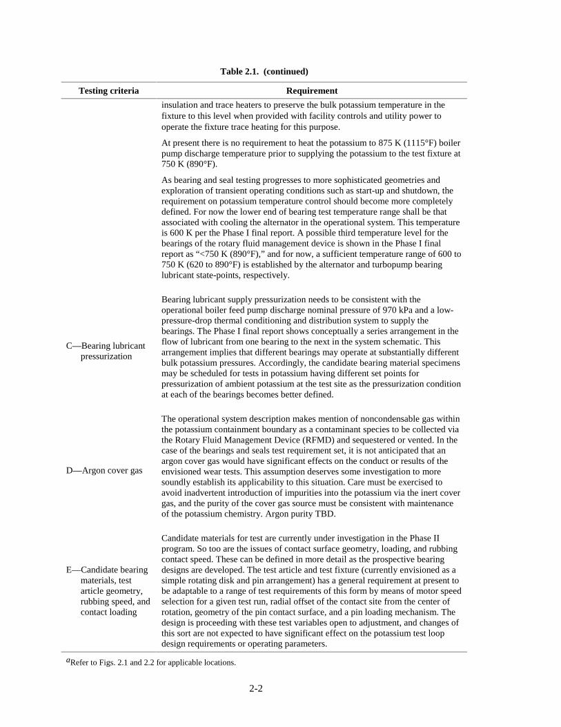
insulation and trace heaters to preserve the bulk potassium temperature in the fixture to this level when provided with facility controls and utility power to operate the fixture trace heating for this purpose.
At present there is no requirement to heat the potassium to 875 K (1115°F) boiler pump discharge temperature prior to supplying the potassium to the test fixture at 750 K (890°F).
As bearing and seal testing progresses to more sophisticated geometries and exploration of transient operating conditions such as start-up and shutdown, the requirement on potassium temperature control should become more completely defined. For now the lower end of bearing test temperature range shall be that associated with cooling the alternator in the operational system. This temperature is 600 K per the Phase I final report. A possible third temperature level for the bearings of the rotary fluid management device is shown in the Phase I final report as “<750 K (890°F),” and for now, a sufficient temperature range of 600 to 750 K (620 to 890°F) is established by the alternator and turbopump bearing lubricant state-points, respectively.
C—Bearing lubricant pressurization
Bearing lubricant supply pressurization needs to be consistent with the operational boiler feed pump discharge nominal pressure of 970 kPa and a low-pressure-drop thermal conditioning and distribution system to supply the bearings. The Phase I final report shows conceptually a series arrangement in the flow of lubricant from one bearing to the next in the system schematic. This arrangement implies that different bearings may operate at substantially different bulk potassium pressures. Accordingly, the candidate bearing material specimens may be scheduled for tests in potassium having different set points for pressurization of ambient potassium at the test site as the pressurization condition at each of the bearings becomes better defined.
D—Argon cover gas
The operational system description makes mention of noncondensable gas within the potassium containment boundary as a contaminant species to be collected via the Rotary Fluid Management Device (RFMD) and sequestered or vented. In the case of the bearings and seals test requirement set, it is not anticipated that an argon cover gas would have significant effects on the conduct or results of the envisioned wear tests. This assumption deserves some investigation to more soundly establish its applicability to this situation. Care must be exercised to avoid inadvertent introduction of impurities into the potassium via the inert cover gas, and the purity of the cover gas source must be consistent with maintenance of the potassium chemistry. Argon purity TBD.
E—Candidate bearing materials, test article geometry, rubbing speed, and contact loading
Candidate materials for test are currently under investigation in the Phase II program. So too are the issues of contact surface geometry, loading, and rubbing contact speed. These can be defined in more detail as the prospective bearing designs are developed. The test article and test fixture (currently envisioned as a simple rotating disk and pin arrangement) has a general requirement at present to be adaptable to a range of test requirements of this form by means of motor speed selection for a given test run, radial offset of the contact site from the center of rotation, geometry of the pin contact surface, and a pin loading mechanism. The design is proceeding with these test variables open to adjustment, and changes of this sort are not expected to have significant effect on the potassium test loop design requirements or operating parameters.
aRefer to Figs. 2.1 and 2.2 for applicable locations.

2-3
Fig. 2.1. Baseline Rankine cycle schematic chosen for the 100-kW(e) system.

2-4
Fig. 2.2. Flow schematic for the 115-kW(e) Rankine system.
C
Start Loop Pump
Boiler
Isolation valve
Pump
Turbine/Alternator
Condenser and Radiator
Alternator radiator
RFMD
Pressure drop
Turbine bearing loop radiator
Start Loop Radiator
Return Pump
C
C
B
B
A
D

2-5
2.2 TWO-PHASE FLOW TESTS
In general, the two-phase flow tests to be performed in later program phases require establishing temperature, pressure, and heat load conditions associated with scaled Rankine cycle working fluid conditions developed by scaling the Rankine cycle space-based system described in the Phase I report,1 and outlined in the Phase II proposal.2 2.2.1 Working Fluid
To meet the thermodynamic, heat transfer, fluid dynamic, and other criteria identified in previous Rankine cycle studies, potassium was assumed as the Rankine power cycle working fluid in Phase I. This selection was based on previous studies that examined multiple working fluids. The major criteria in fluid selection revolve around the pressure/temperature curve at saturation conditions. Maximum system operating temperature (generally established by materials limitations) dictates the system operating pressure for the Rankine cycle. Candidate fluids must have reasonably high saturation pressures at maximum operating temperatures while still allowing materials strength criteria to be met. This limits potential fluids to only a few. Thermodynamic differences in the candidate working fluids do not have a major impact on system performance. The selection of potassium was also based on the fact that of the candidate materials, there was significantly more experience with operating and characterizing potassium systems under typical Rankine cycle operating conditions. 2.2.1.1 Purity
Based on reviewed reference material, the potassium contaminants most likely to be present in significant quantities are sodium (due to its systematic presence in the chemical replacement preparation process) and oxygen (due to its pervasive presence in preparation, storage, and transport environments). Each of these can cause problems in loop operations. Substantial amounts of sodium in a potassium boiler/evaporator can lead to instabilities in the two-phase system. Significant oxygen contamination can cause corrosion of loop construction materials (e.g., stainless steel) and formation of alkali metal oxides (represented by oxide, peroxide, and superoxide forms with potassium). The oxides may cause plugging of flow passages where the alkali metal-insoluble sediments collect or may damage moving parts (such as bearings and valve seats).
Based on the references, the present requirement is to minimize loop contamination from oxygen and sodium in the vendor-supplied working fluid by specifying high-purity grade potassium (<50 ppm oxygen and <50 ppm sodium) instead of “commercial grade” (that may have up to 800 ppm oxygen and 2% sodium). Special care must be taken to minimize the introduction of impurities from loop construction residues. Flushing and purification procedures may also be required to reach and maintain purity levels needed for specific tests. 2.2.1.2 Amount
The requirement for loop charge depends on the specific test situation. For two-phase operation, the goal is to maintain the required liquid/vapor distribution in the hot (boiler) and cold (condenser) sides of the loop. Proper account must be taken of the fact that the volume of a given mass charge of potassium liquid may increase by up to 25% upon being taken from its melting point to operating temperature (see following sections).

2-6
2.2.2 Test Conditions
Generally, the required test conditions are based on the tests outlined in the Phase II proposal.2 2.2.2.1 Temperature range
Projected prototypical conditions as described in the Phase I report1 would require operation at temperatures up to 1310 K to duplicate the maximum power cycle operating temperature in the two-phase tests. For Phase II, a two-phase maximum operating temperature of 1000 K (1340°F) was selected as a compromise to approach the projected maximum operating temperature, while allowing the use of materials like stainless steel for loop components (and, thereby, for this phase of the program, avoiding the necessity of expensive refractory metal construction requirements and vacuum containment). The minimum two-phase operating temperature is estimated to be 875 K (1116°F), corresponding to the condenser operating saturation temperature in the Phase I design.
2.2.2.2 Pressure range
Scaled in similar fashion from Phase I results, the projected pressure range for two-phase flow testing would be from about 18 kPa (2.6 psia) [potassium saturation pressure at 875 K (1116°F)] up to 150 kPa (22 psia) (pump exit pressure). Note that the full Phase I design Rankine cycle pressure rise was 950 kPa.
2.2.2.3 Flow range
From the Phase I design, the two-phase potassium Rankine cycle full-flow requirement for a single boiler tube is estimated to be 0.0227 kg/s at approximately 1300 K through one 1-cm-inside diameter, 240-cm-long boiler tube. Note that the full Phase I primary Rankine design had a 12-tube (1-cm-inside diameter each) boiler with a total flow of 0.272 kg/s. Due primarily to the very large potassium vapor density difference between 1300 K (2.98 kg/m3) and 1000 K (0.372 kg/m3), scaling compromises are necessary. A 1.58- cm inside diameter (1/2-in. schedule 40 pipe), 240-cm-long boiler tube was selected with a maximum flow of 0.01 kg/s for the two-phase scaled experiments. To allow operation over a representative span, the minimum two-phase test flow requirement was selected as 0.0050 kg/s (50% of full flow). 2.2.2.4 Heat load (boiler/condenser) range
The amount of heat added in the heater/boiler and rejected in the cooler/condenser must be sufficient to achieve desired heat fluxes for heat transfer tests. Based on the Phase I results, the boiler heat load design limit is estimated to be 47.4 kW per boiler tube at approximately 1300 K. Note that the full Phase I primary Rankine design employs a boiler heat load of 569 kW spread over 12 boiler tubes. The corresponding compromise heat load for the 1000 K boiler tests was chosen to be 22.8 kW. To allow operation over a representative range, the minimum two-phase test heat load requirement was selected as 11.4 kW. Auxiliary trace heating with appropriate insulation is planned to accommodate local component and/or loop temperature profile requirements. To maintain steady-state conditions, the amount of heat removed in the condenser (as well as heat losses from the remainder of the loop) must match the net heat added by the boiler, trace heating system, and active components (pump, side stream measurement, purification systems, etc.).

2-7
2.3 HEAT PIPE TESTS
Heat pipes developed for the Rankine cycle heat rejection system would be subjected to a number of tests. Successful completion of the tests would provide the system design with heat pipe hardware at the TRL level of not less than five. All of the specific performance requirements are to be generated at the end of the design and optimization phases; therefore, all testing criteria presented in this section are mostly qualitative. 2.3.1 Transport Capacity
Thermal transport performance is one of the major heat pipe design parameters. The ability of the heat pipe to transport the required amounts of thermal energy in the entire temperature range needs to be verified experimentally. The maximum transport power of a heat pipe used in the Phase I trade study is 4 kW assuming a condenser length of 2 m. Maximum power is highly dependent on the operating temperature and transport lengths; therefore, the value for the final design must be validated through experimentation. The zero-gravity (0-g) performance of the heat pipe can be verified by testing the heat pipe completely horizontal. To reduce gravitational effects, the wick structure is made as shown in Fig. 1.4—filling the lower most segment of the inside diameter. The performance margins and sensitivity of the performance to the heat pipe angle with respect to the gravitational field would be studied during the heat pipe performance tests by positioning the evaporator below and above the condenser at different elevations. 2.3.2 Conductance
Another important heat pipe parameter is its conductance, which can be calculated as the ratio of the maximum power transferred divided by the temperature difference between the evaporator and condenser. The importance of this parameter is very significant, because the temperature difference between the heat source with a fixed temperature and the condenser determines the condenser temperature and ultimately the weight of the radiator associated with the heat pipe condenser. This parameter can be measured in conjunction with the transport capacity without additional test activities. 2.3.3 Material Compatibility and Service Life
Material compatibility is one of the main parameters that affects the lifetime of the heat pipe and the degree of performance degradation at the end of life. Because the performance of refractory metal (Nb–1Zr) in combination with potassium is relatively well understood, no major difficulties are expected. However, any nuance of fabrication can introduce contamination that can affect service life and performance. The entire manufacturing process, including materials, cleaning, charging, and fluid purification must be verified. It is anticipated that a representative sample of a heat pipe (material and processing technique) would be set for life test operation. The heat pipe would be tested while refluxing at the maximum operating temperature, with periodic (initially monthly and after the first 6 months—quarterly) performance mapping. Monitoring the condenser temperatures would help to determine the presence of noncondensible gases. The amount of noncondensible gases should be minimal. The ability of the heat pipe to perform would be evaluated at the end-of-life test (end of the Phase II effort).
2-8
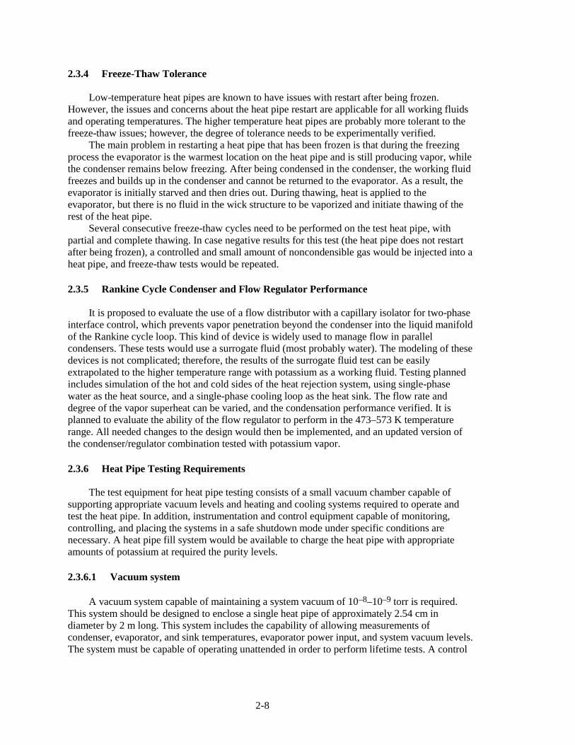
2.3.4 Freeze-Thaw Tolerance
Low-temperature heat pipes are known to have issues with restart after being frozen. However, the issues and concerns about the heat pipe restart are applicable for all working fluids and operating temperatures. The higher temperature heat pipes are probably more tolerant to the freeze-thaw issues; however, the degree of tolerance needs to be experimentally verified.
The main problem in restarting a heat pipe that has been frozen is that during the freezing process the evaporator is the warmest location on the heat pipe and is still producing vapor, while the condenser remains below freezing. After being condensed in the condenser, the working fluid freezes and builds up in the condenser and cannot be returned to the evaporator. As a result, the evaporator is initially starved and then dries out. During thawing, heat is applied to the evaporator, but there is no fluid in the wick structure to be vaporized and initiate thawing of the rest of the heat pipe.
Several consecutive freeze-thaw cycles need to be performed on the test heat pipe, with partial and complete thawing. In case negative results for this test (the heat pipe does not restart after being frozen), a controlled and small amount of noncondensible gas would be injected into a heat pipe, and freeze-thaw tests would be repeated. 2.3.5 Rankine Cycle Condenser and Flow Regulator Performance
It is proposed to evaluate the use of a flow distributor with a capillary isolator for two-phase interface control, which prevents vapor penetration beyond the condenser into the liquid manifold of the Rankine cycle loop. This kind of device is widely used to manage flow in parallel condensers. These tests would use a surrogate fluid (most probably water). The modeling of these devices is not complicated; therefore, the results of the surrogate fluid test can be easily extrapolated to the higher temperature range with potassium as a working fluid. Testing planned includes simulation of the hot and cold sides of the heat rejection system, using single-phase water as the heat source, and a single-phase cooling loop as the heat sink. The flow rate and degree of the vapor superheat can be varied, and the condensation performance verified. It is planned to evaluate the ability of the flow regulator to perform in the 473–573 K temperature range. All needed changes to the design would then be implemented, and an updated version of the condenser/regulator combination tested with potassium vapor. 2.3.6 Heat Pipe Testing Requirements
The test equipment for heat pipe testing consists of a small vacuum chamber capable of supporting appropriate vacuum levels and heating and cooling systems required to operate and test the heat pipe. In addition, instrumentation and control equipment capable of monitoring, controlling, and placing the systems in a safe shutdown mode under specific conditions are necessary. A heat pipe fill system would be available to charge the heat pipe with appropriate amounts of potassium at required the purity levels. 2.3.6.1 Vacuum system
A vacuum system capable of maintaining a system vacuum of 10–8–10–9 torr is required. This system should be designed to enclose a single heat pipe of approximately 2.54 cm in diameter by 2 m long. This system includes the capability of allowing measurements of condenser, evaporator, and sink temperatures, evaporator power input, and system vacuum levels. The system must be capable of operating unattended in order to perform lifetime tests. A control

2-9
system capable of maintaining and monitoring appropriate vacuum levels is necessary for these tests. 2.3.6.2 Control and data acquisition
A control system is necessary to monitor and maintain system vacuum and evaporator temperature levels at a user-defined temperature within ±10 K by adjusting heat input to the evaporator. A similar control of heat sink temperature is necessary. The data acquisition system must be capable of automatically shutting down the experiment. Shutdown signals may include evaporator or condenser overtemperature, loss of vacuum, and loss of heat sink. 2.3.6.3 Potassium purity and loading
During the fill operation, potassium purity levels must be maintained at (TBD), with (TBD) kgs of potassium loaded in the heat pipe. 2.3.6.4 Heat pipe system measurements
The minimum required types, locations, number, accuracy, and range of heat pipe measurements are provided in Table 2.2.
Details of the heat pipe design are described in a separate report.2
Table 2.2. Heat pipe measurement requirements
Measurement Location Number Measurement range Accuracy
Condenser 3 290–900 K ±5 K Evaporator 3 290–900 K ±5 K Temperature Sink 3 250–400 K ±5 K
Power Heater (evaporator)
1 0–5 kW ±0.1 kW
Vacuum Chamber 1 0–0.1 MPa ±10-? Torr 2.4 REFERENCES
1. G. L. Yoder, Jr., et al., Technology Development Program for an Advanced Potassium Rankine Power Conversion System Compatible with Several Space Reactor Designs—Final Phase I Report, ORNL/TM-2004/214, September 2004.
2. “Technology Development Program for an Advanced Potassium Rankine Power Conversion System Compatible with Several Space Reactor Designs—Phase II Proposal,” Oak Ridge National Laboratory internal document, June 2004.
3. “Heat Pipe Development for Rankine NEP Phase 2,” Swales Aerospace, September 2005.

2-10

3-1
3. TEST FACILITY DESIGN AND OPERATING REQUIREMENTS
The primary objectives of the program are to redevelop the techniques necessary to build and operate potassium test facilities; to perform testing that increases the TRL of the Rankine cycle; specifically to initiate wear testing of potassium-lubricated bearings; and characterize the thermal-hydraulic behavior of potassium at high temperatures. Achieving this level of understanding requires the construction and operation of a closed-loop piping system or test loop suitable for continuously circulating nearly pure potassium at high temperatures.
Potassium is a very common chemical element found worldwide. In its pure state, potassium metal has excellent heat-transfer properties that can be useful for high-temperature space power conversion applications. However, there are risks associated with handling and using potassium. Potassium is classified as a hazardous material because it reacts violently with water and certain other chemical compounds. These reactions can produce products that cause severe caustic and thermal burns to eyes and skin. Under certain environmental conditions, potassium can even self-ignite and burn. Controlling these hazards is a key requirement for test loop design and operation.
Three separate engineered barriers are incorporated into the design of the system used to contain the potassium and prevent it from adversely affecting humans and the natural environment during a possible loss-of-potassium containment event. They include
1. a stainless steel piping system that serves as the primary leak tight pressure boundary for the confined potassium,
2. an insulated splash shield, and 3. a ventilated enclosure.
Conceptual designs of the stainless steel piping system, splash shield, and ventilated enclosure are described in Sect. 6.
This defense-in-depth approach is considered an effective way to ensure facility safety because it builds in layers of protection against release of hazardous materials so that no one layer by itself, no matter how good, is completely relied upon. To compensate for potential human error and mechanical failure, these layers of protection provided by successive barriers minimize the potential for a release that could adversely affect the human or natural environment.1
Fire protection engineering standards and building code requirements for the engineered barrier systems are provided in the International Building and Fire Codes.2,3 Other national code and consensus standard rules that influence the design and construction of these systems are contained in the National Electric Code, International Mechanical Code, Code for Process Piping, and the Manual of Steel Construction.4–7 3.1 STAINLESS STEEL PIPING SYSTEM
The overall focus of the testing is evaluating potassium-lubricated rotating bearing and seal systems and characterizing the thermal-hydraulic performance of potassium at temperatures up to 1000 K (1340°F). In this loop design, high-temperature potassium is continuously circulated through a closed-loop stainless steel piping system. A preliminary conceptual design for the potassium test loop and its key components is described in Sect. 6.2. The piping system would be designed in accordance with rules provided in the Code for Process Piping6 adopted by the American Society of Mechanical Engineers (ASME) and constructed using welded type 316L stainless steel components manufactured through the vacuum remelt process. This piping system serves as the primary leak tight pressure boundary for the confined potassium.
In addition to these requirements, boiling and single-phase test requirements must be considered in design of the stainless steel piping system. For boiler tests, the test loop must have the capability of supplying 875 K (1116°F) potassium to a boiler test section at a flow rate of

3-2
0.01 kg/s. Under these conditions, the boiler exit pressure is 80 kPa, and the pressure rise across the pump is approximately 150 kPa (22 psi). In addition, the test loop must provide approxi-mately 23 kW of power to an electrically heated boiler test section and reject 23 kW of heat through the air-cooled condenser. The test loop must be able to maintain a potassium oxygen content of 50 ppm or less, during these tests. For single-phase tests, the loop must also have the capability of supplying 600 K to 750 K (620 to 890°F) potassium to the bearing and seal test section at a maximum flow rate of 0.2 kg/s. Maximum required pressure drop through the bearing and seal test fixture is 1400 kPa. Potassium purity levels must be maintained at an oxygen content of 10 to 50 ppm (exact number TBD) during this testing. Based on these required operating modes and conditions, and including some conservatisms, it was decided to establish the loop pressure and temperature design conditions as
• 1800 kPa (262 psia) at 750 K (890°F), • 788 kPa (114.7 psia) at 1000 K (1340°F), and • 0 kPa (0 psia) at 1000 K (1340°F).
Potassium needed for loop operations can be purchased from a chemical supplier and shipped to ORNL in approved, properly labeled metal shipping containers. Pressurized argon would be used to force liquid potassium out of the heated metal shipping containers, through interconnected piping, and into the heated sump tank. Additional potassium storage and handling requirements are discussed in Sect. 3.4.
Before proceeding with final design of the stainless steel piping system, specifications for candidate construction materials with suitable chemical and mechanical properties need to be identified and evaluated. Chemical and mechanical properties are important because they affect the design and fabrication of the piping system as well as the purity of the potassium that circulates through the test loop. Proper material selection can also have a direct influence on the overall quality of the test results. Besides adequate temperature-dependent properties, candidate construction materials must also satisfy ASME Boiler and Pressure Vessel Code and Process Piping Code acceptance criteria. Other potentially important considerations include alloying constituents, chemical compatibility, price and availability, weldability, corrosion resistance, and susceptibility to stress corrosion cracking.
In developing the conceptual design for the potassium test loop piping system discussed in Sect. 6.2, Type 316 stainless steel was selected because it has adequate mechanical properties at temperatures up to 1000 K, and it is chemically compatible with potassium under most anticipated operating conditions. Variations of this material including Type 316L stainless steel manufactured using the vacuum remelt process were also considered for certain test loop components because the chemical composition of this material is less variable and its lower carbon content is considered more desirable for certain types of testing. However, final selection of loop construction materials was still on-going when the project was cancelled and would need to be revisited before final design of the loop was complete. 3.1.1 Components
The various loop components must be compatible with the working fluid and, in concert, provide the capability to satisfy the testing criteria and achieve system operating conditions. In addition, they must enable measurements that verify the attainment of such conditions and quantify the associated performance characteristics.

3-3
3.1.1.1 Boiler
The boiler provides the main heat input to the loop during testing. As currently envisioned, it consists of a single tube with the potassium flowing on the inside and segmented mineral-insulated electrical heaters with external thermal insulation providing heat to the flowing potassium. The plan is to provide specific heat flux profiles within the desired test range using controlled direct current power at about 200 V (Ref. 8). The boiler is designed for power levels up to approximately 25 kW using indirect electrical heating. Approximately ten surface temperature measurements are required on the boiler tube, and both boiler inlet and outlet potassium temperature measurements are necessary. Measurements of the electrical heater element temperature would also be made to detect heater failure. Pressure measurements at the boiler inlet and outlet are to be included in the design. Power level to the boiler must be measured to determine boiler heat flux levels. 3.1.1.2 Condenser
The condenser (or cooler) serves as the main heat rejection unit for the test loop during normal operations. It must be able to reject up to 25 kW of energy by air cooling. As currently envisioned, it consists of a single tube (probably in a helical/annular configuration) with potassium flowing on the inside and air as the coolant on the outside. Adjustable (flow and temperature) forced circulation of ambient air is provided by a separate heat removal system. This system includes an intake and exhaust duct, fan, and electrical resistance heater. Condenser tube surface temperature measurements are required as well as potassium inlet and outlet temperatures and pressures. Cooling air inlet and outlet air temperature measurements are also necessary. A summary of parameters relating to condensing mode operations is presented in Table 3.1.
Table 3.1. Condenser parameters for potassium test loop
Annular condenser/cooler property (air outside)
Phase II two-phase Units
Condenser heat load 22.8 kW
Potassium inlet temperature 1000 K
Potassium mass flow 0.0100 kg/s
Potassium tube outside diameter 3.34 cm
Air inlet temperature 289 K
Air inlet pressure 101325 Pa
Air mass flow 0.454 kg/s
Air volume flow 0.381 m3/s
Air temperature rise 50.0 K
Air tube inside diameter 12.80 cm
Air wetted perimeter 0.507 m
Length 4.60 m
Heat transfer area 0.4827 m2
Heat flux 47237 W/m2
Air flow area 0.0120 m2
Air velocity 31.786 m/s
Air Reynolds number 194470

3-4
3.1.1.3 Bearing and seal test article
The objective of bearing and seal testing is to provide data on the wear properties of candidate bearing material combinations under prototypic operating conditions. Requirements for a test fixture for conducting these tests is described in detail in Table 3.2. It consists of an electric-motor-driven spindle, a shaft feed-through assembly, and a test chamber in which test articles are exposed to a high-temperature liquid potassium environment. The test fixture is designed to conduct rubbing contact tests of candidate bearing and seal materials where pin-on-disk or similar wear testing is performed. During testing, a load is applied, and wear performance
Table 3.2. Bearing and seal test fixture requirements
Test fixture component
Requirement
A—Power supply to motor and controller
Drive motor and associated speed control equipment: Preliminary electrical power requirement: 230/460V, 3 phase, 60 Hz for 2-hp motor and controller. Spindle speed measurement to be provided by TBD. A means for detecting anomalous drive loads and shutting off the drive power is part of the bearing and seal test fixture.
B—Spindle lower bearing temperature
Temperature sensor is used for monitoring the temperature of the bearing along with appropriate signal conditioning, display, and recording. An overtemperature warning is recommended to prevent damage to the drive spindle from heat conduction from the test article.
C—Quill shaft cooling gas supply system
A cooling gas is used for thermal isolation section of the test article. Gas may be room temperature air, nitrogen, or argon. Flow rate to be remotely adjustable. An interlock is recommended that prevents heating the tester if the coolant gas is not flowing. Approximate requirements: Pressure less than 80 psig, 1/4-in. tube size.
D—Low-pressure hot argon gas vent system
This is a low-pressure vent to carry away the hot barrier gas that leaks to the atmospheric side of the feed-through seal. Under design operating conditions, it does not contain potassium contaminants. However, overpressurization of the test fixture may cause potassium to enter this system. A vent system open to the atmosphere and external to the test article is required.
E—Hot argon supply system
This system serves two functions. (1) It provides the barrier fluid to the feed-through seal to prevent the escape of potassium from the test fixture. (2) It regulates the test fixture internal pressure. Preliminary requirements: Heated argon gas at 400–800°F, temperature approximately matched to desired potassium temperature; pressure 5–220 psig; flow rate TBD, interface connection is 1/4-in. tube fitting. Argon purity to be determined based on maintaining test loop potassium purity level.
F—Argon barrier gas pressure safety interlock system
A port is provided on the test article for sensing the argon barrier pressure. It is recommended that this pressure be measured and used as input to a warning system that alarms when the test article is not properly pressured with argon.
G—Liquid potassium supply
A port is provided on the test fixture for receiving pressurized, heated liquid potassium. Preliminary requirements are pressure—5 to 200 psig; temperature—800°F max.; interface connection TBD; flow rate—the 0.0227 kg/s (0.05 lbm/s) is acceptable for the planned Phase II materials tests; however, the fluid temperature drop through the tester is expected to be 20–50°F with this flow rate, and the flow rate is insufficient for hydrostatic bearing testing if desired in future programs. It is recommended that flow be increased by a factor of 2 to minimize fluid heat loss and by a factor of 5 to enable future hydrostatic bearing testing. Potassium purity TBD.

3-5
evaluated based on comparisons of test article examination results obtained before and after testing.
The test vessel is a “dry sump” design. Details are described in Table 3.3. A pool of liquid potassium is maintained within the containment vessel into which the test articles are immersed. A continuous flow of liquid potassium overflows this pool into the containment vessel. The vessel drains by gravity into the test vessel drain subsystem.
The vessel is pressurized by an argon barrier seal flow arrangement. Argon flowing into the vessel is vented from the top of the vessel through a baffle arrangement that separates most of the entrained potassium. The separated potassium drains out the bottom of the vessel along with the overflow from the pool. Argon flows out the top of the vessel into the argon-potassium vent subsystem.
Pressure in the liquid potassium loop and the argon vent system is equalized by a shunt line between the potassium separation system and the high-pressure argon vent system. Pressure in the systems is maintained by an orifice at the exit of the argon vent system that restricts argon flow. The system pressure is set by regulating the argon pressure to the barrier seal. Argon vent flow rate is set by the orifice size and system operating pressure. Argon flow rate can be set so that the
Table 3.3. Bearing and seal test vessel and test vessel drain system requirements
Test vessel component
Requirement
H1—Liquid potassium return
Requirements are similar to G: liquid potassium supply.
H2—Containment vessel liquid potassium drain port
Requirements: pressure—5 to 200 psig; temperature—800°F max.; interface connection TBD.
H3—Potassium/hot argon gas separation system
This system serves to maintain the level of liquid potassium below a maximum operating level in the containment vessel. The maximum level is established by the baffle system within the containment vessel to assure minimal carryover of entrained potassium into the hot argon vent system. Requirements are similar to G: liquid potassium supply.
H4, H5, H7—Hot argon/potassium vent system
This system provides for the safe disposal or recirculation of hot argon that flows in contact with liquid potassium. Requirements: pressure—5 to 200 psig; temperature—800°F max.; Interface connection TBD; flow rate—set by orifice size. A fixed orifice is anticipated, the size to be determined in concert with the barrier seal design.
H6—Potassium trap Purpose of this component is to remove trace potassium from the argon stream before release to the environment. Pressure—5 to 200 psig; temperature—800°F max.; potassium content TBD.
H8—Test chamber pressure
Measurement of the test chamber gas pressure and barrier seal differential pressure is required. A warning system based on differential pressure that assures that the chamber pressure does not approach the argon barrier seal pressure within a set margin is also required.
J1—Tester head/potassium loop disassembly interface
A bolted flange seals the containment vessel to the tester head. Access is required above the test fixture for removal of the drive motor/spindle assembly from the test head and removal of the tester head from the containment vessel. Estimated maximum weight of the assembly is 273 kg (523 lbf). A support structure is also required on which the test fixture is mounted.
J2—Containment vessel/potassium loop connection interfaces
Three connections are required: liquid potassium supply, liquid potassium drain, and hot argon vent/potassium vent. Additional inert gas connections are required to the tester head.
J3—Test fixture heater The test fixture includes electric heaters to preheat and maintain temperature. A temperature control system is included.

3-6
barrier pressure is 5-psi (minimum) above the vessel pressure, thus ensuring that potassium does not migrate through the barrier seal to the atmospheric side where it could contact air.
The intent of the containment vessel design is that it be a semipermanent part of the potassium test loop. That is, when access to test articles is required, the tester head containing the feed-through seal assembly, rotating mandrel, and stationary test article holder are lifted up and out of the containment vessel for decontamination and inspection, while the containment vessel and pool remain connected to the test loop piping. 3.1.1.4 Pump
Based on Mausteller et al., Brooks, and Ohse, electromagnetic pumps are preferred for achieving working fluid circulation within small test loops.9–11 Use of an electromagnetic pump in the potassium test loop has distinct advantages over a mechanical pump. It avoids penetration of the pressure-retaining boundary and eliminates potential bearing and sealing problems encountered with mechanical pumps that operate in the working fluid.
Other factors that influence the pump design and performance are related to the boiling and bearing seal test requirements. For the boiling tests, the pump must have the capability of operating with 875 K (1116°F) potassium and supplying a boiler test section at a flow rate of 0.01 kg/s. Pressure rise across the pump is approximately 150 kPa (22 psi). For bearing and seal tests, the pump must also have the capability of supplying 750 K (890°F) potassium to the bearing and seal test section at a maximum flow rate of 0.2 kg/s. Maximum required pressure drop through the bearing and seal test fixture is 1400 kPa. 3.1.1.5 Flowmeter
According to Mausteller et al. electromagnetic flowmeters are the most frequently used for liquid-metal flow measurements.9 Their potential advantages include minimal pressure drop penalty and wide flow and temperature range measurement capability. They also avoid penetration of the pressure-retaining boundary. To satisfy testing requirements, the flowmeter must be capable of operating at a system temperature of 1000 K and measure single-phase potassium flows from 0.01 to 0.2 kg/s. 3.1.1.6 Sump tank
The sump tank is attached to the lowest part of the test loop piping system and serves as a reservoir for potassium. Up to 100 lb of potassium can be transferred to the sump tank from shipping containers supplied by the potassium vendor. Details of the filling operations are described in Sect. 4.1.4. The sump tank is also used to charge the test loop with potassium as discussed in Sect. 4.1.6 and to receive the potassium charge when the test loop is drained. Design of the sump tank includes electrical resistance heating elements capable of maintaining the potassium inventory at a maximum temperature of 922 K (1200°F), and gettering material for use during sump tank hot trapping operations (discussed in Sect. 4.1.11.1). Peterson12 reports that zirconium has been used successfully as a gettering material capable of achieving 7- to 9-ppm oxygen levels after 50 h at 922 K (1200°F). Operating details are given in Longo, Tippets, Tippets and Converse, and Tippets and Ferguson.13–20
Design of the sump tank should be in accordance with applicable requirements in Sect. VIII, Division I of the ASME Boiler and Pressure Vessel Code.21 Key considerations include a maximum operating pressure of 1600 kPa (232 psig); a maximum operating temperature of 1000 K (1340°F) (however not simultaneously); thermal-shock considerations; gettering material; and connection ports for a dip tube, cover gas, vent line, drain, and fill openings. Pressure relief

3-7
for the sump tank is provided by one or more self-closing pressure relief devices that are part of the argon cover gas system. 3.1.1.7 Valves
Manually operated and automatic valves are included in the piping system design to control potassium flow to various components during normal and abnormal operations. For example, a remotely operated valve is located in the sump argon supply line and, when closed, isolates the supply line from the argon supply system. Another remotely operated valve, when open, vents the argon from the sump to the argon vent system. During both single-phase and two-phase flow testing, the potassium charge is kept in the test loop by providing an argon overpressure in the sump tank sufficient to lift and hold the potassium in the loop. In the event of a power outage, when a loss-of-potassium containment event is detected, or at the completion of routine testing, the argon vent valve opens, the argon supply line valve closes, and the overpressure is released, thereby allowing potassium to drain into the sump tank. To provide inventory control capability, a manually operated valve is also installed in this drain line. Other valves may be installed at various locations and used to control potassium pressure and flow to specific components. Based on experience reported by Lyon and Mausteller et al.,9 formed bellows-sealed valves are likely required, and stop valve applications have a longer service life than throttling valve applications, which involve chattering and fatigue. 3.1.1.8 Level indicators
Continuous readout level indicators are required to measure potassium charge quantities in the sump tank and to monitor and maintain liquid levels for the bearing and seal test article experiments. Based on Lyon, Brooks, McCulloch, Duncombe, and Mausteller et al.,8,9,22,23 J-type resistance probes meet these requirements. 3.1.1.9 Temperature sensors
Temperature measurements are required both to monitor and maintain appropriate temperature levels at locations throughout the test loop piping system. Temperature values are needed to assure proper operation and to quantify heat transfer performance in selected loop components (boiler, condenser, etc.). Based on Sawochka and Yarosh and Gnadt,24,25 chromel-alumel (Type K) thermocouples are well suited for the anticipated environment and provide sufficient EMF output over the projected operating temperature range. 3.1.1.10 Purity monitor
A method of monitoring potassium purity is required to assure that adequate purity levels are maintained and to indicate when additional purification measures are needed. The potassium oxygen monitoring system must be capable of measuring oxygen content ranging down to 10 ppm (exact value TBD). Mausteller et al.9 suggest the use of a plugging meter as a convenient operational method for monitoring potassium purity. A sampling method with amalgamation and vacuum diffusion analysis techniques was employed by Yarosh and Gnadt.25 Electrochemical measurement methods are described by Ohse.11 The particular method employed depends on the measurement range and required accuracy for a particular test situation.

3-8
3.1.1.11 Hot trap
Hot trapping is the chemical conversion of soluble impurities in the working fluid (such as oxygen, carbon, nitrogen, and hydrogen) into insoluble compounds by means of a getter material (e.g., zirconium). This technique is recommended by Peterson and Mausteller et al.9,12 for reducing and controlling potassium impurity levels. Hot trapping can be accomplished by adding getter material to the sump tank and by adding dedicated hot trap vessels to in-line and bypass line piping systems. The method employed depends on the required level of potassium purity for the specific test situation. Peterson reported the use of a gettering grid located in the potassium head tank for in-line hot trapping.12 Sawochka reported the use of a hot trap with zirconium gettering material in a bypass line in parallel with the condenser.24 3.1.1.12 Expansion tank
To control the potassium liquid level in the test loop during wear and bearing tests, an expansion tank is likely to be required. Argon cover gas pressure is used for pressure control, and a level indicator located in the tank monitors loop inventory. 3.1.2 Material Requirements
The upper operating temperature for the potassium test loop was selected to be 1000 K (1340°F). This value represents a compromise that approaches the projected maximum prototypical operating conditions but allows the use of less costly construction materials like stainless steel. Use of stainless steel avoids the need for more expensive refractory metal construction and the need for vacuum containment. To reduce the possibility of carbon stringers per O’Connor,26 the stainless steel used for construction of test loop piping and components needs to comply with type 316L requirements and be manufactured using the double re-melt process. 3.1.3 Electrical Requirements
Up to 60 kW of electrical power at up to 480 V is required to operate the test loop and associated electrical equipment. Backup or emergency power may also be required to operate the ventilation system during a power outage. 3.1.4 Data Acquisition System Requirements
The test loop data acquisition system is required to record and process a variety of sensor data produced by
• thermocouples, • pressure transducers, • electrical resistance devices, • electrical power controllers, • electrical current and voltage meters, • flow meters, and • liquid level indicators. The minimum required types, locations, number, accuracy, and range of test loop measurements are provided in Table 3.4.

3-9
Table 3.4. Minimum test loop instrumentation requirements
Measurement Location Number Measurement range Accuracy Boiler inlet 2 0–1000 K ±2 K Boiler outlet 2 0–1000 K ±2 K Condenser inlet 2 0–1000 K ±2 K Condenser outlet 2 0–1000 K ±2 K Pump inlet 2 0–1000 K ±2 K Pump outlet 2 0–1000 K ±2 K Sump 2 0–1000 K ±2 K Expansion tank 2 0–1000 K ±2 K Hot trap (loop) 2 0–1000 K ±2 K Cold trap (loop) 2 0–1000 K ±2 K
Potassium temperature
Hot trap (sump) 2 0–1000 K ±2 K Condenser cooling 2 0–1000 K ±2 K Enclosure 2 0–1000 K ±2 K Air temperature Splash shield 2 0–1000 K ±2 K Boiler tube 10 0–1000 K ±0.5 K Boiler heaters 10 0–1000 K ±2 K Condenser tube 5 0–1000 K ±2 K Sump 2 0–1000 K ±2 K
Surface temperature
Expansion tank 2 0–1000 K ±2 K Boiler inlet 1 0–1500 kPa ±20 kPa Boiler outlet 1 0–100 kPa ±10 kPa Boiler DP 1 0–1500 kPa ±20 kPa Condenser inlet 1 0–100 kPa ±10 kPa Condenser inlet 1 0–100 kPa ±10 kPa Condenser DP 1 0–100 kPa ±10 kPa Pump inlet 1 0–100 kPa ±10 kPa Pump outlet 1 0–1500 kPa ±20 kPa Pump DP 1 0–1500 kPa ±20 kPa Expansion tank 1 0–1500 kPa ±20 kPa
Pressure
Sump tank 1 0–1500 kPa ±20 kPa Sump 1 TBD
Liquid level Expansion tank 1 TBD Enclosure vent 1 TBD Loop vent 1 TBD Argon supply 1 TBD
Oxygen content
Loop potassium 1 0–50 ppm ±5 ppm Enclosure 1 0–5% ±0.1%
Hydrogen content Loop vent 1 0–5% ±0.1% Loop potassium 1 0–0.2 kg/s ±0.005 kg/s
Flow Argon cover 1
3.1.5 Argon Pressurization and Cover Gas System
The argon system is designed to maintain a continuous cover of argon over the potassium in the loop. In addition, it is used to control system pressure and liquid inventory. This system must be capable of supplying enough pressure to maintain the desired system pressure and therefore requires an argon supply and a vent system. This system is used to bring potassium from the sump into the loop, and maintain the desired system pressure during operation. It is also used to

3-10
maintain an argon cover over the liquid potassium under all loop conditions. The system requires both a supply and vent design capable of maintaining the desired argon purity levels and preventing release of potassium vapor to the environment. 3.1.6 Vacuum System
A vacuum system capable of pumping the loop down to a vacuum level of (TBD) would be used during loop conditioning and for startup of the facility. The evacuation process requires incorporation of a device or devices that assure that no potassium vapor is discharged to the atmosphere. 3.2 INSULATED SPLASH SHIELD
The insulated splash shield functions as an engineered barrier against the effects of a potassium release by containing liquid potassium that escapes from the stainless steel piping system during a loss-of-potassium containment event. 3.2.1 Insulated Splash Shield Description
Main splash shield components include a drip pan, four walls, and a ceiling. These components are designed as double-walled, insulated panels, but the shield is not airtight. Inside surfaces of the wall and ceiling panels and the drip pan are constructed using stainless steel sheet metal. To provide access to the piping system for installation and repair, the splash shield has removable or hinged wall panels capable of providing the required access. The drip pan functions as a secondary containment with sufficient volume to contain at least 50 kg (110 lb) of liquid potassium. Access inside the splash shield should not be permitted when potassium is being circulated through the piping system at high temperatures.
To ensure that potassium in the stainless steel piping system remains a liquid and drains completely back to the sump tank, the splash shield design includes an electrical resistance heating system capable of maintaining the space inside the enclosure at a minimum temperature of 394 K (250°F). Alternatively, trace heating of the piping can be used as a means of ensuring loop temperatures over the liquidus temperature of potassium. The type and thickness of insulation used to construct the insulated wall and ceiling panels will be dictated by the final heating scheme chosen.
Structural steel framing members are installed inside the splash shield to support the wall and ceiling panels, the stainless steel piping system, power and instrumentation wiring, access ladders and work platforms, and handrail systems necessary for worker convenience and safety. To eliminate a potential fire hazard, only nonflammable construction materials are used inside the splash shield. 3.2.2 Insulated Splash Shield Requirements
Although there are no Occupational Safety and Health Administration (OSHA) guidelines for limiting surface temperatures to avoid injury, a maximum surface temperature of 120°F is assumed as a design requirement for outside surfaces of the splash shield. This requirement allows direct skin contact with one of these surfaces for approximately 100 s without causing an irreversible epidermal injury.27
Structural design and construction of the splash shield walls, ceiling, and framing system are based on requirements contained in the Manual of Steel Construction7 and in 29 CFR 1910, Subpart D for walking and working surfaces.28 Electrical design and construction must be in

3-11
accordance with the National Electric Code.4 Penetrations through the wall and ceiling panels of the splash shield are required for electrical wires, argon cover gas piping, and intake and exhaust ductwork. 3.3 VENTILATED ENCLOSURE
The ventilated enclosure provides the third line of defense against the consequences of a loss-of-potassium containment event. Its primary functional requirements include
• preventing water from entering the enclosure thus limiting the potential for potassium-water reactions;
• removing particulate matter, harmful vapors, fumes, and gases from inside the enclosure during a loss-of-potassium containment event; and
• providing a 2-h fire rating suitable for classification of the enclosure as a High Hazard Group H-2 occupancy facility.
3.3.1 Ventilated Enclosure Description
The ventilated enclosure is a water-tight, self-supported structure that surrounds the insulated splash shield. It would be constructed in Building 5800, Room D111, and is referred to as the Liquid-Metal Test Facility (LMTF) (Table 3.5). Approximate overall dimensions of the LMTF measure 20 ft by 26 ft by 22 ft tall. To prevent water from entering the enclosure in the event of a roof leak, water line break, sprinkler system release, or chilled water system malfunction, the top surface of the steel enclosure floor is located at least 3 in. above the surrounding concrete floor. This steel floor system protects the concrete floor slab from possible exposure to high-temperature potassium and the potentially damaging consequences of potassium-concrete reactions.
Table 3.5. LMTF design requirements
Design requirement Description
Available floor area for lay down and assembly of LMTF within Room D111: 1,600 ft2
Overall floor area of Room D111 is approximately 100 ft by 50 ft.
Maximum available height in Room D111: 25 ft
Distance from concrete floor surface to bottom surface of permanent building components.
Minimum required rectangular floor area of LMTF: 475 ft2
Preferred outside dimensions:
19 ft by 25 ft minimum
20 ft by 26 ft maximum
Minimum floor-to-ceiling height of LMTF: 22 ft
The minimum inside height of the LMTF (LMTF floor to lowest point of ceiling) shall be 22 ft.
Fire rating of LMTF: 2 h (See Preliminary Fire Hazard Analysis)
H2 Occupancy (LMTF contains more than 4 lb of water reactive and pyrophoric alkali metal, potassium and lithium).
Height of LMTF floor slab above concrete floor of Room D111: 3-in. minimum, 4-in. maximum
A 3-in. (minimum) thick concrete floor slab that is placed on top of the concrete floor in Room D111 is required to exclude water from within the LMTF. This minimum height ensures that water does not flow into the LMTF if the sprinklers in Room D111 are activated. A maximum height of 4 in. is specified to reduce the size of the ramps required to provide forklift access to the LMTF.

3-12
Table 3.5. (continued)
Design requirement Description
Minimum allowable uniform floor live load for the LMTF: 100 psf
The allowable floor live load in Room D111 is 150 psf.
Floor surface: smooth and level portland cement concrete
The top surface of the LMTF floor slab shall be level within ± 1/8 in. and trowelled smooth Application of organic coating lay-ers or sealant materials on concrete surface is not permitted.
Minimum allowable uniform roof live load for the LMTF: 50 psf
Roof storage should not be permitted, but worker access on the roof is necessary.
Roof construction
Roof shall be pitched and watertight to protect the LMTF from ingress of water resulting from fire sprinkler releases and leaks from the roof drain system. The ceiling shall also be pitched to promote natural venting of hydrogen from the LMTF. The roof panels shall have bidirectional fire resistance and have a 2-h fire rating.
Roof penetrations A watertight roof penetration shall be provided through the LMTF to
accommodate the exhaust duct for the ventilation system.
Maximum modular roof panel width
Roof panels shall be of a size that fit through a 10-ft by 10-ft rollup door. Joints between adjacent roof panels shall be watertight.
Modular wall panel construction Wall panels shall have bidirectional fire resistance and have a 2-h
fire rating. The size of individual components shall fit through a 10-ft by 10-ft rollup door.
Exterior LMTF wall surfaces
Exterior wall surfaces of the LMTF shall be watertight sheet metal that is primed and painted. The sheet metal shall extend below the top surface of the LMTF concrete floor slab by at least 1 in. Adja-cent wall and roof panels shall be joined to create a barrier against ingress of water into the LMTF resulting from fire sprinkler releases and leaks from the roof drain system. The bottom of the wall panels shall be mechanically fastened to the LMTF concrete floor slab and the joint between the floor slab, and the bottom sur-face of the wall panels shall be sealed to prevent ingress of water.
Interior LMTF wall and ceiling surfaces
Interior LMTF surfaces shall be stainless steel sheet metal that are not primed or painted. The stainless steel sheet metal shall be at least 18 gauge, and overlapping joints between adjacent pieces of sheet metal shall be sealed with either Thermiculite or Flexcarb gasket material by the Flexitallic Group, Inc., Houston, Texas, or approved equal.
Seismic design The LMTF shall be designed to resist earthquake motion. See
Preliminary Fire Hazard Analysis, Sect. 4.2.3.
Rollup doors
Two each watertight rollup doors shall be installed to provide access to the LMTF. Each door shall include an electric motor and be at least 6 ft wide (preferably 8 ft wide or wider) and at least 18 ft tall. The doors shall have a fire rating that is consistent with the 2-h fire rating for the wall panels. Door seals shall be replaceable. When completely closed, each door shall be designed to prevent water from entering the LMTF. Awnings shall be installed above the doors. If possible, the doors shall be located near the centers of the north and west walls of the LMTF. Each door shall be secured by means of a locking device. See Preliminary Fire Hazard Analysis, Sects. 2.3 and 6.5.

3-13
Table 3.5. (continued)
Design requirement Description
Passage doors
Two each watertight passage doors shall be installed to provide access to the LMTF. Each door shall be at least 3 ft wide and at least 6 ft 8 in. tall, include a window, and have a fire rating that is consistent with the 2-h fire rating for the wall panels. Door seals shall be replaceable. When completely closed, each door shall be designed to prevent water from entering the LMTF. Awnings shall be installed above the doors. If possible, the doors shall be located near the northeast and southwest corners of the LMTF and secured with locking devices. See Preliminary Fire Hazard Analysis, Sects. 2.3 and 6.5.
Access ramps and landings
A removable access ramp shall be provided for each rollup door. The ramps shall attach to the concrete floor or wall of the LMTF and be suitable for providing forklift access to the LMTF. If required by applicable building or fire codes, the sides of the ramps shall be sloped to avoid a stumbling hazard. A removable landing (metal grating type structural assembly) shall be provided for each passage door, if required.
Viewing window
One viewing window shall be installed in the LMTF. The window shall be at least 3 ft by 3 ft and have a fire rating that is consistent with the 2-h fire rating for the wall panels. Window shutters are permitted to achieve the required fire rating. See Preliminary Fire Hazard Analysis, Sect. 2.3.
Ceiling lighting fixtures with two switches
Eight each (eight each located 2 ft from LMTF walls). Light intensity shall be at least 60 foot candles near the floor immediately upon switch activation.
110-V convenience outlets (inside LMTF)
Eight each (centered 48 in. above LMTF floor surface).
110-V convenience outlets (outside LMTF)
Eight each (centered 18 in. above floor surface of Room D111).
Emergency lighting Emergency lighting shall be provided inside the LMTF. See
Preliminary Fire Hazard Analysis, Sect. 6.4.
Fire detection and alarm system Smoke detection, manual fire alarm pull stations, and local fire
alarm notification shall be provided. See Preliminary Fire Hazard Analysis, Sect. 3.4.
Electrical panels
Electrical panels shall be installed on the outside walls of the LMTF. One panel shall control electrical power supplied to the LMTF and the ventilation fan. If required by the ORNL or Oak Ridge City Fire Department, a different panel shall be provided for making electrical connections to the fire detection and alarm system equipment supplied as part of the LMTF. Connections to these panels can be performed by ORNL staff or an authorized contractor.
Class D fire extinguishers Portable fire extinguishers, applicable signs, and acceptable methods
of wall anchorage shall be provided. See Preliminary Fire Hazard Analysis, Sect. 3.3.
DOT Class 4.3 placards Two appropriately sized DOT Class 4.3 placards, shown in Fig. 3.1,
shall be provided on the outside walls of the LMTF.

3-14
Table 3.5. (continued)
Design requirement Description
Mechanical penetration access: 4-ft2 (minimum)
Four each (locations to be specified), 2-h fire rating with provisions for installing and removing pipes and tubes that pass through the wall of the LMTF. If possible, each penetration assembly should be capable of being removed from the wall panel and taken to a work area where it can be cut or modified to accommodate the required number and sizes of penetrations. In addition, the Seller shall provide acceptable methods or procedures for sealing and resealing theses penetrations with approved fire-stop materials.
Electrical penetration access: 4-ft2 (minimum)
Four each (locations to be specified), 2-h fire rating with provisions for installing and removing pipes, tubes, wires, and conduits that pass through the wall of the LMTF. Each penetration assembly shall be capable of being removed from the wall panel and taken to a work area where it can be cut or modified to accommodate the required number and sizes of penetrations. In addition, the Seller shall provide acceptable methods or procedures for sealing and resealing these penetrations with approved fire-stop materials.
Electrically powered ventilation system
Note: The ventilation system shall be capable of
• using air from Room D111 to sweep heat and potassium reaction products out of the LMTF and splash shield and
• exhausting these products up a stack to the surrounding atmosphere.
The roof-mounted ventilation fan shall operate continuously at a minimum of two different fan speeds. Speeds shall be selectable using a switch located on the outside wall of the LMTF. The ven-tilation system shall include a noncombustible filtration system. This system shall include removable filter elements that are capa-ble of removing up to 95% of the potassium reaction products (particulate matter) from the exhaust gas stream. The ventilation system shall also be capable of naturally venting hydrogen that may accumulate near the ceiling (ridge) of the LMTF. Electrical power for the ventilation fan shall be provided from Room D111 using the existing roof penetration, if possible.
Stack height above roof: 12 ft (minimum at stack exhaust)
Minimum exhaust duct air velocity: 3,000 ft/min.
Maximum exhaust duct air velocity: 5,000 ft/min.
Minimum centrifugal fan capacity: 2,000 cfm
Maximum centrifugal fan capacity: 5,000 cfm
Fire dampers: at locations specified in the Preliminary Fire Hazard Analysis
See Preliminary Fire Hazard Analysis, Sects. 2.2.1 and 2.3.
Exhaust ventilation duct
Note: It may be necessary to remove the ductwork that is currently connected to the existing roof penetration and the ventila-tion fan located above the roof penetration prior to installation of the ventilation system.
The exhaust duct for the ventilation system shall penetrate the roof of the LMTF and, if possible, exit Room D111 through an existing roof penetration. The duct shall be noncombustible, enclosed in a 2-h fire rated assembly through Room D111, and electrically grounded. The exhaust duct intakes shall be located at the highest point in the LMTF and near the top of the splash shield. The exhaust duct intake connection to the splash shield shall be termi-nated 20 ft above the floor surface of the LMTF. Connection of the exhaust duct intake to the splash shield is to be performed by ORNL staff. Air from inside Room D111 shall be used as the sup-ply for the ventilation system. Intakes for this air shall be located through the walls of the LMTF near the floor at one or more loca-tions on the oppose side of the LMTF from the exhaust intakes. UL-approved fire dampers shall be installed in the intake openings. See Preliminary Fire Hazard Analysis, Sects. 2.2.1 and 2.3.

3-15
Fig. 3.1. DOT placard for Class 4.3 materials.
Routine access to the LMTF is through hinged doors located on the north and west enclosure
walls. Certain wall panels may also be removable to allow installation of the splash shield and stainless steel piping system components.
The LMTF includes a powered ventilation fan and ductwork system that continuously supplies fresh air to the enclosure. The ductwork system includes filter elements capable of removing solid potassium reaction products and other fine particulate matter that may be generated if a loss-of-potassium containment event occurs. 3.3.2 Ventilated Enclosure Requirements
Specific fire protection engineering and life-safety requirements for the ventilated enclosure are discussed in the fire hazard analysis (FHA) that was prepared by ORNL Fire Protection Engineering.29 Design requirements for the ventilation system including fan capacity, air velocity, and required number of air changes per hour are established by personnel safety standards. Mechanical and electrical design and construction of the ventilation system must be in accordance with the International Fire, Building, and Mechanical Codes2,3,5 and the National Electric Code.4 Structural design and construction of the ventilated enclosure walls, ceiling, and floor system must be based on requirements contained in the Manual of Steel Construction.7
Access inside the ventilated enclosure is permitted when potassium is being circulated through the piping system provided proper personal protective equipment is used and specified precautions are taken to ensure worker safety. During routine operations, the maximum surface temperature of the splash shield should not exceed 120°F, and the ventilation system should maintain the temperature inside the ventilated enclosure slightly above ambient. 3.4 POTASSIUM STORAGE AND HANDLING REQUIREMENTS
Potassium is to be supplied and shipped to ORNL by a chemical supplier in metal shipping containers that are approved by the U.S. Department of Transportation (DOT) for this purpose. Figures 3.2 and 3.3 show different sizes of metal shipping containers approved for potassium transportation. These metal shipping containers can also be used to store potassium on-site in

3-16
Fig. 3.2. 14-kg metal DOT approved shipping container for transporting potassium.

F
ig. 3
.3.
Lar
ge m
etal
shi
ppin
g co
ntai
ner
for
tran
spor
ting
pot
assi
um.
3-17

3-18
accordance with International Building and Fire Code requirements.2,3 Code requirements permit storage in the following locations:
• in an approved storage cabinet if it � has a High Hazard Group H-2 rating, and � is used solely for potassium storage;
• inside the ventilated enclosure which has a High Hazard Group H-2 rating; and • in an approved storage cabinet at another ORNL facility.
No special procedures are required to transport potassium from one ORNL location to
another provided the potassium is confined in a DOT-approved metal shipping containers.30 When potassium is transferred from the metal shipping containers to the sump tank, the
splash shield will be partially open for access to the sump tank. After a metal shipping container and the sump tank are heated to about 395 K (250°F), pressurized argon gas is be used to force the liquid potassium from the metal shipping container to the sump tank. A representative piping configuration for this purpose is shown in Fig. 3.4. Overpressure protection during the transfer is be provided by a self-closing pressure relief device installed in the argon piping system. Additional information about potassium transfer operations is provided in Sect. 4.2.1.1.
Fig. 3.4. Conceptual design of the stainless steel piping system
(potassium manufacturer’s design recommendation). 3.5 EX-LOOP POTASSIUM PURIFICATION SYSTEM
A potassium purification system external to the experimental test loop may be necessary to provide a potassium charge to the loop with sufficient purity levels or may be necessary to purify the potassium removed from the loop in preparation for a recharge. This facility is expected to be a stand-alone piece of equipment capable of receiving impure potassium from the loop, purifying the potassium by way of hot and cold traps, and recharging potassium to the loop or other potassium-containing equipment. This system must be capable of accepting (TBD) kg of potassium with oxygen contents up to (TBD) ppm and purifying the potassium to (TBD) ppm oxygen levels.

3-19
3.6 EX-LOOP CLEAN-UP SYSTEM
A stand-alone potassium clean-up system is required to clean equipment and components removed from the potassium experimental facility to allow modifications, repair, and replacement of parts and equipment in the loop. The cleanup equipment is expected to consist of an inert gas (argon) supply in combination with a superheated steam injection system that allows reaction of all residual potassium in or on this equipment. The system includes a means of collecting the potassium hydroxide generated during this process, venting the hydrogen and other off-gases from the process, and monitoring hydrogen and oxygen levels in the off-gas stream.
3.7 REFERENCES
1. “Preparation Guide for U.S. Department of Energy Nonreactor Nuclear Facility Documented Safety Analyses,” DOE-STD-3009-94, U.S. Department of Energy, Washington, DC, July 1994.
2. “International Fire Code,” 2003 Edition, International Code Council, Falls Church, Virginia.
“International Building Code,” 2003 Edition, International Code Council, Falls Church, Virginia.
4. “National Electric Code,” NFPA 70, National Fire Protection Association, Quincy, Massachusetts, 2005.
5. “International Mechanical Code,” 2003 Edition, International Code Council, Falls Church, Virginia.
6. “Process Piping,” ASME B31.3, American Society of Mechanical Engineers, New York, 2002.
7. ASD Manual of Steel Construction, 9th Edition, American Institute of Steel Construction, Chicago, Illinois, 1989.
8. R. McCulloch, Delta-m Corporation, personal communication, 2005. 9. J. W. Mausteller, F. Tepp, and S. J. Rodgers, Alkali Metal Handling and Systems
Operating Techniques, Gordon and Breach, Science Publishers, Inc., 1967. 10. R. D. Brooks, Editor, Alkali Metals Boiling and Condensing Investigations, Vol. I—
Experimental Program, NASA CR-54050, Contract NAS 5-681, SPPS, MSD, General Electric Company, June 1, 1964.
11. R. W. Ohse, Editor, Handbook of Thermodynamic and Transport Properties of Alkali Metals, Blackwell Scientific Publications, 1985.
12. J. R. Peterson, High-Performance “Once-Through” Boiling of Potassium in Single Tubes at Saturation Temperatures of 1500° to 1750°F, NASA CR-842, General Electric Company, Missile and Space Division, Cincinnati, Ohio, 1967.
13. J. Longo, “Alkali Metal Boiling and Condensing Investigations,” Quarterly Progress Report No. 6, NASA CR 54037, Contract NAS 3-2528, SPPS, MSD, General Electric Company, April 20, 1964.
14. F. E. Tippets, “Alkali Metal Boiling and Condensing Investigations,” Quarterly Progress Report No. 7, NASA CR 54038, Contract NAS 3-2528, SPPS, MSD, General Electric Company, April 20, 1964.
15. F. E. Tippets, “Alkali Metal Boiling and Condensing Investigations,” Quarterly Progress Report No. 8, NASA CR 54138, Contract NAS 3-2528, SPPS, MSD, General Electric Company, October 20, 1964.
16. F. E. Tippets and G. L. Converse, “Alkali Metal Boiling and Condensing Investigations,” Quarterly Progress Report No. 9, NASA CR 54215, Contract NAS 3-2528, SPPS, MSD, General Electric Company, October 20, 1964.

3-20
17. F. E. Tippets and G. L. Converse, “Alkali Metal Boiling and Condensing Investigations,” Quarterly Progress Report No. 10, NASA CR 54308, Contract NAS 3-2528, SPPS, MSD, General Electric Company, April 20, 1964.
18. F. E. Tippets and G. L. Converse, “Alkali Metal Boiling and Condensing Investigations,” Quarterly Progress Report No. 11, NASA CR 54405, Contract NAS 3-2528, SPPS, MSD, General Electric Company, April 20, 1964.
19. F. E. Tippets and G. L. Converse, “Alkali Metal Boiling and Condensing Investigations,” Quarterly Progress Report No. 12, NASA CR 54739, Contract NAS 3-2528, SPPS, MSD, General Electric Company, April 20, 1964.
20. F. E. Tippets and D. R. Ferguson, “Alkali Metal Boiling and Condensing Investigations,” Quarterly Progress Report No. 13, NASA CR 54890, Contract NAS 3-2528, SPPS, MSD, General Electric Company, April 20, 1964.
21. “Rules for Construction of Pressure Vessels,” ASME Boiler and Pressure Vessel Code, Section VIII, Section I, American Society of Mechanical Engineers, New York, 2002.
22. R. N. Lyon, Editor-in-Chief, Liquid Metals Handbook, 1952. 23. E. Duncombe, “Some Instrumental Techniques for Hostile Environments,” J. Physics E:
Scientific Instrumentation, 17 (1984). 24. S. G. Sawochka, Thermal and Hydraulic Performance of Potassium During
Condensation Inside Single Tubes, NASA CR-851, General Electric, Missile and Space Division, Cincinnati, Ohio (1966).
25. M. M. Yarosh and P. A. Gnadt, The Intermediate Potassium System—A Rankine Cycle Test Facility, ORNL 4025, Oak Ridge National Laboratory, 1968.
26. G. O’Connor, Boeing-Rocketdyne, personal communication, 2005. 27. “Standard Guide for Heated System Surface Conditions that Produce Contact Burn
Injuries,” ASTM Designation: C 1005-03, American Society for Materials and Testing, West Conshohocken, Pennsylvania, 2003.
28. “Walking-Working Surfaces,” 29 CFR 1910, Subpart D, Occupational Safety and Health Administration, Washington, D.C.
29. “Liquid Metal Test Facility Preliminary Fire Hazard Analysis,” Fire Protection Engineering Internal Document, Oak Ridge National Laboratory, Oak Ridge, Tennessee, Rev. 0, May 6, 2005, Rev. 1, May 31, 2005.
30. Oak Ridge National Laboratory On-Site Transportation Safety Document, ORNL/M-808, Revision 1, Oak Ridge National Laboratory, Oak Ridge, Tennessee, April 2000.

4-1
4. SYSTEM OPERATIONS
All test loop operations are to be conducted inside the splash shield with the ventilation system operating. This requirement ensures maximum protection for workers and the environment during both normal and abnormal operations. 4.1 NORMAL OPERATIONS
During normal operations, potassium is confined in a closed system consisting of leaktight pipes, valves, fittings, tanks, and containers. Electrical resistance heating elements provide trace heating for the various piping system components. Argon cover gas inside the piping system is used to prevent potassium from making contact with oxygen and water vapor present in ambient air. The argon cover gas system includes one or more self-closing pressure relief devices that provide overpressurization protection for the test loop. Discussions about various activities, considerations, and requirements for normal operations are presented in the following sections. Pressure and temperature limits for cleaning, filling, charging, hot flushing, hot trapping, single-phase flow, and two-phase flow testing operations are summarized in Table 4.1.
Table 4.1. Pressure and temperature requirements for key operations
Operating requirement Operation
Temperature limit Pressure limit
Postconstruction test loop cleaning 395 K (250°F) Several hundred micrometers of mercury vacuum
Filling 355 K (180°F) 10 kPa (1.5 psig)
Charging 450 K (350°F) 100 kPa (15 psig)
Hot flushing
• During circulation • At discard
1000 K (1340°F) 750 K (890°F)
100 kPa (15 psig) 100 kPa (15 psig)
Hot trapping (sump tank) 922 K (1200°F) 100 kPa (15 psig)
Single-phase testing 750 K (890°F) 1600 kPa (232 psia)
Two-phase testing 1000 K (1340°F) 150 kPa (22 psia)
4.1.1 General Testing Considerations
Potassium needed for loop operations would be purchased from a chemical supplier and shipped to ORNL in DOT-approved, properly labeled metal shipping containers as discussed in Sect. 3.4. Pressurized argon is used to force liquid potassium out of the heated metal shipping containers, through interconnected piping, and into the heated sump tank. Potassium would not be delivered to the splash shield until the stainless steel piping system has been constructed, inspected, tested, properly cleaned, evacuated, and charged with argon. When all of these activities are completed, a small-diameter stainless steel piping system with an argon pressurization system, protected from overpressurization by a self-closing pressure relief device, would be attached to the metal shipping container and used to transfer the potassium from the metal shipping container to the sump tank. This piping system uses mechanical rather than welded pipe connections. The total amount of potassium added to the sump tank would not exceed 45.4 kg (100 lb).

4-2
Under normal operating conditions, up to 45.4 kg (100 lb) of potassium is permitted inside the splash shield at a particular time. This inventory is located in the sump tank prior to loop startup and under normal shutdown conditions. During normal operations, some of the potassium in inventory is used to charge the piping system, while the remainder of the potassium stays inside the sump tank. Argon overpressure in the sump tank is used to maintain liquid inventory in the loop. For shutdown operations, the argon overpressure is released, scrubbed of potassium vapor, and vented to atmosphere. The potassium in the piping system then drains by gravity into the sump tank. After all of the potassium has drained into the sump tank, a manual valve located between the loop and the sump can be closed to isolate the potassium in the sump from the empty loop. To ensure that potassium is not exposed to air during these operations, the sump tank and the piping system would be continuously connected to the argon cover gas pressurization systems.
As testing progresses, periodic disassembly and reassembly of the piping system would be performed to remove and install various test articles and heat transfer system components or to remove contaminants located inside the piping system. Prior to disassembly, the potassium inventory would be verified before the sump tank is disconnected from the piping system. A dry steam and argon mixture could then be injected into the piping system to remove residual potassium. A similar method can be used to clean the sump tank after the potassium has been transferred to an approved metal shipping container. The rate of the potassium-water reaction is controlled by slowly adding steam to a flowing argon gas stream. During this operation, water vapor, hydrogen, and argon gases are released into the ventilated enclosure, and the aqueous potassium hydroxide that forms when the water reacts with the potassium is collected in a storage vessel. In addition, personal protective equipment and solid reaction products, if any, associated with disassembly and reassembly of loop components would be collected, containerized, and properly labeled. Practices that are to be used to transfer or dispose of potassium and its reaction products are discussed in Sect. 5.5. 4.1.2 Postconstruction Test Loop Cleaning
Inside surfaces of the test loop piping system must be thoroughly cleaned before potassium can be added to the system. Although careful specification and cleaning of materials and components before construction and judicious construction procedures (welding, for example) reduce the likelihood of significant contamination, residue such as oil, grease, water, and oxides that remain after loop construction can produce undesirable carburization, hydride embrittlement, galling, and plugging consequences. The postconstruction test loop cleaning procedure recommended by Mausteller et al.1 includes the following steps:
1. Flush with hot water containing detergent. 2. Rinse with water to remove detergent. 3. Wash with acetone or an equivalent, but less hazardous, chemical to enable water removal. 4. Evacuate at ambient temperature to remove acetone and other remaining volatiles. 5. Heat with evacuation (suggested to several hundred micrometers of mercury at greater than
250°F) to remove remaining gaseous contaminants. 6. Heat with inert gas flow to sweep remaining traces. 7. Pressurize with inert gas to maintain system purity. 4.1.3 Filling Preparations
After postconstruction test loop cleaning operations are completed, filling operations can begin. The filling operation involves transferring potassium from a DOT-approved shipping container to the sump tank. To minimize the introduction of potential contaminants during the

4-3
filling operation, a fill preparation procedure involving evacuation and heating of the sump tank and connecting piping is required to remove moisture and gases. Trace and component-specific heaters are employed to achieve and maintain the required component temperatures. Heating to at least 250°F at a vacuum level of several hundred micrometers has been suggested by Mausteller et al.1 Other references specify heating above 300°F at vacuum levels to 25 μm.
The filling procedure that is adopted would likely be based on conservative recommendations provided in these references, but, as a minimum, preparations for filling require
• preheating the sump tank and connecting piping to 450 K (350°F), and • evacuating the sump tank and connecting piping down to 2 μPa (27 μm mercury). 4.1.4 Filling Operation
When fill preparations are completed, the filling procedure can start. Based on the reference information, the preferred procedure for accomplishing the filling process is to use a cover gas to force potassium from the shipping container through a filter to the sump tank. To minimize the amount of impurities transferred from the shipping container to the sump tank, the recommended temperature for this procedure is slightly above the melting point of the potassium. Mausteller et al.1 recommend approximately 14 K (25°F) above the melting point. For potassium with a melting point of 337 K (146°F), this corresponds to a filtering temperature of 351 K (172°F). However, the same reference recommends a potassium filtering temperature of 355 to 366 K (180 to 200°F), that is, 18 to 30 K (34 to 54°F) above the melting point.
If the filtering temperature is too far above the melting point of the potassium, filtration efficiency of impurities with high temperature-dependent solubility may be compromised. However, if the filtering temperature is near the melting point, potassium metal adjacent to the filter could freeze. Ohse and Mausteller et al.2 recommend a sintered stainless steel filter with approximately 10-µm pore diameter. This pore size represents a compromise among filter flow resistance, plugging capacity, and impurity removal efficiency considerations. As before, trace and component-specific heaters are employed to achieve and maintain the required component temperatures.
For filling to be possible, the cover gas pressure applied to the shipping container must be enough above the maximum potassium liquid leg head to promote reasonable flow through the piping and the filter. Steps involved in the filling procedure include the following:
• Bring shipping container, 10-μm filter, sump tank, and connecting piping to 355 K (180°F) which is 18 K above the 337 K melting point of potassium—the lower end of the range recommended by Mausteller et al.1 for potassium.
• Provide regulated cover gas pressure to 10 kPa (1.5 psig) that is equivalent to about 1 m of liquid potassium (larger vertical displacements between the shipping container and the charge tank require greater applied pressure).
• Open the associated fill valves to begin the filling process, monitor the liquid level in the sump tank, and close the valves after filling is completed.
4.1.5 Charging Preparations
The charging operation is defined as the process of transferring potassium from the sump tank to the test loop without introducing potentially harmful contaminants. To prepare for filling, moisture and gases must be removed from the piping system. This is accomplished by evacuating and heating the piping system components using trace and component-specific heaters to achieve and maintain the required temperature levels. Suitable conditions suggested by Mausteller et al.1 for this operation include a temperature of at least 395 K (250°F) and a vacuum level of several

4-4
hundred micrometers of mercury. The following charge preparation requirements, which are based on a conservative reading of this reference, involve heating the test loop piping and associated components to 450 K (350°F) and evacuating the test loop to a pressure of 10 μPa (133 μm mercury). 4.1.6 Charging Operation
The preferred procedure for charging the test loop with potassium is based on reference information. It involves establishing the sump tank, test loop components, and connecting piping safely above the melting point of potassium as described in Sect. 4.1.5 and using cover gas pressure to force potassium from the sump tank to flow into the piping system. The cover gas pressure applied to the sump tank must be sufficiently above the maximum potassium liquid leg head to promote reasonable flow through the piping. Achieving appropriate charge conditions requires maintaining the temperature of test loop piping and components, sump tank, and connected piping at 450 K (350°F), providing regulated cover gas pressure to 100 kPa (15 psig) which is equivalent to about 10 m of liquid potassium, and opening the appropriate valves. 4.1.7 Start-Up Melt Preparations
To prevent possible damage to test loop piping and components and to allow their proper operation, the temperature of these components must be maintained at or above 400 K (260°F), which is 63 K (113°F) above the melting temperature of potassium. 4.1.8 Wetting Verification
To ensure proper operation of electromagnetic pumps and flow meters, Mausteller et al.1 recommend that special precautions be taken to induce surface wetting. In particular, they recommend maintaining all sections of the test loop above the “solubilization temperature” [589 K (600°F)] and circulating potassium at full flow for at least 1 h to ensure that any traces of hydroxide melt and that remaining grease and oxide residue reacts with the potassium.
Past experience with stainless steel systems for alkali metals provides evidence that wetting onset begins when a sudden increase in pump performance or flow meter readings is observed. Requirements for achieving wetting conditions involve heating the test loop piping and component to 650 K (710°F) and operating the pump until full flow is available. This operation is performed for at least 2 h while pump performance and flow meter readings are continuously monitored for indications of sudden change. 4.1.9 Hot Flushing Preparations
According to Mausteller et al., Ohse, and Peterson,1,3 gross impurities remaining in test loops can be eliminated by a hot flushing process that involves circulating several fresh charges of working fluid at the maximum operating temperature. After each charge is circulated for an extended period (Brooks4 reported a time of 100 h), the charge is removed at elevated temperature and discarded. For the potassium test loop, the required hot flush temperature is 1000 K (1340°F) with the pump operating at full available flow for at least 100 h. 4.1.10 Hot Flushing Operations
After the potassium charge has circulated at 1000 K (1340°F) for at least 100 h, the potassium charge, including impurities, is discarded. To maximize the effectiveness of this hot

4-5
flushing operation, the potassium should be discarded at a temperature of at least 700 K (800°F). For the potassium test loop, the required discard temperature is 750 K (890°F). Because high-temperature potassium flows into the sump tank during the hot flushing operation, one of the design requirements for the sump tank involves thermal-shock considerations. 4.1.11 Hot Trapping Operations
To further control and reduce impurities in the potassium, Mausteller et al. and Peterson1,3 recommend hot trapping to achieve chemical conversion of soluble impurities such as oxygen, carbon, nitrogen, and hydrogen into insoluble compounds by means of a getter material (e.g., zirconium). 4.1.11.1 Sump tank hot trapping
Peterson3 reported successfully employing zirconium gettering grids in the sump tank to achieve 7- to 9-ppm oxygen levels after 50 h at 922 K (1200°F). Additional operating details are provided in references by Longo, Tippets, Tippets and Converse, and Tippets and Ferguson.5–12 For the potassium test loop, required sump tank hot trapping involves increasing the temperature of the sump tank, which contains the potassium charge and the getter grid material, to 922 K (1200°F) and maintaining the sump tank at this temperature for 50 h or longer until the required level of potassium purity is achieved. 4.1.11.2 In-line loop hot trapping
Peterson also reported the use of a gettering grid located in the working fluid for in-line hot trapping. Although no specific control conditions are indicated for this requirement, it may be necessary to install a gettering grid in the potassium head tank to accomplish in-line hot trapping. 4.1.11.3 Bypass loop hot trapping
Sawochka reported the use of a hot trap with zirconium gettering material in a bypass line located in parallel with the condenser.13 Because no specific control conditions are indicated for this situation, bypass hot trapping may or may not be required. 4.1.12 Noncondensable Gas Collection and Removal Conditions
Tippets and Ferguson describe the use of a head tank downstream of the working fluid condenser to collect and remove noncondensable gases, particularly during startup and shakedown operations.12 However, no specific operating conditions were indicated. 4.1.13 Nucleation Initiation
For two-phase testing, Sawochka, Tippets and Converse, and Yarosh and Gnadt describe the use of “hot fingers” and artificial nucleation sites to reduce the potential for excessive liquid superheats and associated instabilities in alkali metals.8–11,13,14 The conditions required to initiate nucleation are likely to be specific to each two-phase situation.

4-6
4.1.14 Cover Gas Considerations
A cover gas is used to minimize contamination and to provide potassium pressure and level control. Selection considerations for candidate cover gases include requirements for chemical inertness and low-solubility properties relative to the potassium, ease of containment, and availability from commercial sources in high purity at low cost. Based on these requirements, argon was selected over nitrogen (possible nitriding of structural materials) and helium (higher cost, difficult to contain). 4.1.14.1 Purity
To minimize the introduction of contamination from the cover gas into the test loop (oxide, hydroxide, hydrogen, and hydrate formation from oxygen and water vapor contaminants), Mausteller et al.1 indicate that impurity levels of less than 5 ppm oxygen and less than 5 ppm water vapor are required. This requirement means that commercially available argon is “not tolerable” because it typically contains 10- to 20-ppm oxygen and water vapor. The same reference recommends installing a NaK bubbler between the cover gas supply and the test loop to provide purification capability. However, in a more recent reference, Desreumaux et al.15 state that a NaK bubbler should not be used for cover gas purification. Their work indicates that (1) the NaK does not chemically transform all traces of water vapor (some remains in the form of hydrated products) and (2) as resulting product mixtures form heterogeneous crusts, the cover gas develops preferential flow paths. Such a situation means that it is nearly impossible to judge the efficiency or useful life of such a purifier. An alternative suggestion requires passing the cover gas through a heated titanium medium (sponge) to purify the argon. 4.1.14.2 Amount
The amount of cover gas needed for testing is dictated by the flow requirements for the bearing and seal test article. 4.1.15 Single-Phase Flow Testing
Single-phase flow tests involving the bearing and seal test article would be conducted at a temperature of 600 to 750 K (620 to 890°F) and a maximum pressure of 1600 kPa (232 psi). Cover gas flow requirements are based on the needs of the test article. 4.1.16 Two-Phase Flow Testing
Two-phase flow boiling and condensing tests would be conducted at a temperature of 1000 K (1340°F) (at the boiler exit) and a maximum pressure of 150 kPa (22 psia) (at the pump exit). This temperature limit was selected because it represents a compromise that approaches the projected maximum prototypical operating conditions of the potassium Rankine cycle, but allows the use of less costly construction materials like stainless steel. 4.2 ABNORMAL OPERATING CONDITIONS
During normal operations, certain events could occur and trigger an abnormal operating condition. These events include a
• loss-of-potassium containment event,

4-7
• power outage, and • pressure excursion. 4.2.1 Loss-of-Potassium Containment
Although the stainless steel piping system is constructed with leak tight joints and pressure-retaining components suitable for high-temperature potassium service, three loss-of-potassium containment events could result in exposure of potassium to air or water. These events are defined in Table 4.2 and discussed in the following sections. The types and anticipated amounts of material released during these events are summarized in Sect. 5.2.2.1. Emergency response actions and waste disposal requirements for a loss-of-potassium containment event are discussed in Sects. 5.4 and 5.5, respectively.
Table 4.2. Loss-of-potassium containment events
Event Description
1 Potassium transfer—A loss-of-potassium containment event could occur during transfer of potassium from metal shipping container to sump tank inside splash shield
2 Primary pressure boundary component failure—A loss-of-potassium containment event could occur due to failure of a primary pressure boundary component caused by
• thermal fatigue
• weld or pipe defect
• overstress condition
• electrical arcing
• physical damage and material degradation
• metal loss due to corrosion, erosion, or cavitation
3 Loss-of-argon cover gas—A loss-of-potassium containment event could occur due to loss-of-argon cover gas pressure
4.2.1.1 Event 1—potassium transfer
Potassium is a solid at room temperature with a melting point of 146°F. To transfer potassium from the metal shipping container to the sump tank, both vessels are heated to about 250°F to ensure that the potassium remains liquid during the transfer. Pressurized argon is used to force the potassium to flow from the metal shipping container to the sump tank. The argon pressure is controlled, and the argon pressurization system is protected by a self-closing pressure relief device to ensure the vessels are not overpressurized. Limiting the pressure also helps control the potassium leak rate from a faulty mechanical pipe connection or piping component while the leak is detected, and the argon pressure is lowered to stop the leak. Examples of metal shipping containers for transporting and storing potassium and a representative piping configuration for transferring potassium are shown in Figs. 3.1 through 3.3.
Transfer operations are conducted inside the splash shield which may be partially open for access and involve the following activities:
• venting and purging the loop as noted in Sect. 4.1.5; • mechanically connecting piping components between the shipping container cover gas and
dip tube ports, an argon source, and the sump tank fill port; • heating the metal shipping container and the sump tank to melt the potassium so that the
potassium flows from the metal shipping container to the sump tank; • pressurizing the metal shipping container with argon;

4-8
• opening valves on the metal shipping container dip tube line and the sump tank fill port; • monitoring the potassium level in the sump tank; • closing the sump tank, argon source, and metal shipping container valves; • disconnecting the piping components; and • removing the shipping container from the splash shield.
As potassium is being transferred from the metal shipping container to the sump tank, it is possible that a loss-of-potassium containment event could occur. Event scenarios include
• potassium leak at a mechanical pipe connection or piping component, • argon leak resulting in loss-of-argon cover gas pressure, and • failure to completely drain all potassium from interconnecting piping components prior to
disconnecting the metal shipping container from the sump tank.
The maximum amount of potassium that could be exposed to air during the transfer operation is equal to the amount of potassium in the metal shipping container. Exposure of this amount of potassium would require mechanical failure or fracture of the metal shipping container, the sump tank, or the piping system components. Although failure or fracture is possible, stainless steel components at elevated temperatures are resistant to fracture initiation and crack propagation. Therefore, exposure of potassium is not considered likely during potassium transfer operations.
A credible loss-of-potassium containment event during potassium transfer operations would involve no more than 0.1 lb of potassium. This amount of potassium could remain on the walls of a nominal 3/4-in.-diam, schedule 40 stainless steel pipe that connects the metal shipping container to the sump tank after the transfer is completed (the amount of potassium in a nominal 3/4-in.-diam, schedule 40 pipe that is 36 in. long is 1 lb). 4.2.1.2 Event 2—primary pressure boundary component failure
The stainless steel piping and argon cover gas systems that serve as the primary pressure boundary for the confined potassium are discussed in Sect. 3.1. Failure of a component in either of these systems by one or more of the mechanisms described in Table 4.1 could result in loss-of-potassium containment. Factors that influence the amount of potassium that is released when a primary pressure boundary component fails are as follows:
• pressure of the argon cover gas, • location of the failure, • size and type of failure, • temperature of the potassium at the failure location, and • elapsed time between when the release is detected and the remainder of the potassium is
drained into the sump tank.
A credible loss-of-potassium containment event during a pressure boundary component failure would involve [TBD] lb of potassium. This corresponds to the amount of liquid potassium that would flow through a 0.25-in.-diam hole at a pressure of 1800 kPa (262 psig) (the piping system design pressure) for a prescribed period of time [TBD]. During this [TBD] period, the argon flow monitoring system detects an excess flow of argon and triggers an emergency shutdown in which the sump tank overpressure is released, automatically allowing the remaining potassium to completely drain into the sump tank while still maintaining a slight overpressure on the loop components. The temperature of the released potassium could be up to 1000 K (1340����

4-9
4.2.1.3 Event 3—loss-of-argon cover gas
Pressurized argon is used as a cover gas to keep air from contacting potassium-free surfaces. This practice prevents potassium reaction products from forming at these locations. Loss-of-argon cover gas pressure could result in exposure of potassium to air, thereby initiating a loss-of-potassium containment event. This type of event could occur if the supply of argon is exhausted or a leak occurs in the argon cover gas piping system.
To reduce the probability of a loss-of-argon cover gas event, the argon cover gas pressure and flow is continuously monitored to detect an increase or decrease in argon cover gas pressure and to detect excess argon flow. A change in argon cover gas pressure or an increase in argon flow are indications that a loss-of-potassium containment event may be occurring. To prevent overpressurization of the argon cover gas piping system, the piping system includes one or more self-closing pressure relief devices that operate at pressures slightly above the maximum operating pressures. 4.2.2 Power Outage
During normal operations when the test loop is charged with potassium, electrical power is required to
• provide heat needed to maintain the potassium above its melting point; • energize solenoid and flow control valves that are part of the argon and potassium piping
systems; • operate devices that measure temperature, flow, and pressure; • power instrumentation and control system components as well as the potassium pump,
condenser fan motor, and test article motor; and • drive the ventilation blower and control system.
Unscheduled electrical power disruptions would adversely affect the way these components function and could result in abnormal operating conditions.
Whenever a power outage occurs, loop shutdown is triggered. Shutdown operations involve automatically draining the potassium from the piping system into the sump tank and charging the piping system with argon. In addition, the trace heaters and boiler are disconnected from the electrical grid so that overheating cannot occur when power is restored.
To ensure that the ventilation system remains operational during an unscheduled electrical power outage, the ventilation blower and control system is designed to operate in a natural convection mode. This safety requirement ensures that airborne reaction products, including hydrogen gas that may be generated during a power outage, are removed from the ventilated enclosure. 4.2.3 Pressure Excursion
The argon cover gas system is used to control the potassium pressure in the stainless steel piping system and to transfer potassium into the sump tank during normal and off-normal operations involving an unscheduled power outage. Argon cover gas is supplied by compressed-gas cylinders that are connected to a piping system. Besides a flow control valve, pressure regulator, and pressure sensor, the argon cover gas piping system also includes at least one self-closing pressure relief device that provides overpressure protection in the event of a pressure excursion. A self-closing pressure relief device is required for this application to keep air from entering the stainless steel piping system after the pressure stabilizes.

4-10
A pressure excursion could occur
• if a temperature sensor, power controller, or electrical component fails and causes the temperature of the potassium to increase, or
• a flow control valve or pressure regulator fails and allows the argon pressure to increase.
The pressure relief devices are located outside the splash shield but inside the ventilated enclosure so that the argon gas that discharges during a pressure excursion can be removed by the ventilation system. 4.3 DECOMMISSIONING
Prior to final disassembly of the stainless steel piping system, potassium remaining in the piping system would be drained into the sump tank. The sump tank can then be disconnected from the piping system. To permit on-site transportation and safe storage of the potassium, the contents of the sump tank would be transferred to properly labeled metal shipping containers.
Cleanup of the piping system involves injection of steam and argon into the piping system to remove residual potassium that remains on the walls of the stainless steel piping system after the piping system is drained. The rate of the potassium-water reaction is controlled by slowly adding dry steam to a flowing argon gas stream. During this operation, water vapor, hydrogen, and argon gases are released into the enclosure ventilation system (or into a separate stack system designed for this purpose). The aqueous potassium hydroxide that forms when the water reacts with the potassium is collected in a properly labeled container. A cyclic water flush and drain process is used to remove residual potassium hydroxide from the loop piping system. To ensure worker safety during this cleanup operation, personal protective equipment must be worn, and solid reaction products, if any, that are generated must be collected, containerized, and properly labeled.
After the potassium and reaction products are purged from the piping system, disassembly of the piping system can begin. Conventional tools and industrial practices can be used for this work because potassium-related hazards no longer exist. 4.4 REFERENCES
1. J. W. Mausteller, F. Tepp, and S. J. Rodgers, Alkali Metal Handling and Systems Operating Techniques, Gordon and Breach, Science Publishers Inc., 1967.
2. R. W. Ohse, Editor, Handbook of Thermodynamic and Transport Properties of Alkali Metals, Blackwell Scientific Publications, 1985.
3. J. R. Peterson, High-Performance “Once-Through” Boiling of Potassium in Single Tubes at Saturation Temperatures of 1500° to 1750° F, NASA CR-842, General Electric Company, Missile and Space Division, Cincinnati, Ohio, 1967.
4. R. D. Brooks, Editor, Alkali Metals Boiling and Condensing Investigations, Vol. I—Experimental Program, NASA CR-54050, Contract NAS 5-681, SPPS, MSD, General Electric Company, June 1, 1964.
5. J. Longo, “Alkali Metal Boiling and Condensing Investigations,” Quarterly Progress Report No. 6, NASA CR 54037, Contract NAS 3-2528, SPPS, MSD, General Electric Company, April 20, 1964.
6. F. E. Tippets, “Alkali Metal Boiling and Condensing Investigations,” Quarterly Progress Report No. 7, NASA CR 54038, Contract NAS 3-2528, SPPS, MSD, General Electric Company, April 20, 1964.

4-11
7. F. E. Tippets, “Alkali Metal Boiling and Condensing Investigations,” Quarterly Progress Report No. 8, NASA CR 54138, Contract NAS 3-2528, SPPS, MSD, General Electric Company, October 20, 1964.
8. F. E. Tippets and G. L. Converse, “Alkali Metal Boiling and Condensing Investigations,” Quarterly Progress Report No. 9, NASA CR 54215, Contract NAS 3-2528, SPPS, MSD, General Electric Company, October 20, 1964.
9. F. E. Tippets and G. L. Converse, “Alkali Metal Boiling and Condensing Investigations,” Quarterly Progress Report No. 10, NASA CR 54308, Contract NAS 3-2528, SPPS, MSD, General Electric Company, April 20, 1964.
10. F. E. Tippets and G. L. Converse, “Alkali Metal Boiling and Condensing Investigations,” Quarterly Progress Report No. 11, NASA CR 54405, Contract NAS 3-2528, SPPS, MSD, General Electric Company, April 20, 1964.
11. F. E. Tippets and G. L. Converse, “Alkali Metal Boiling and Condensing Investigations,” Quarterly Progress Report No. 12, NASA CR 54739, Contract NAS 3-2528, SPPS, MSD, General Electric Company, April 20, 1964.
12. F. E. Tippets and D. R. Ferguson, “Alkali Metal Boiling and Condensing Investigations,” Quarterly Progress Report No. 13, NASA CR 54890, Contract NAS 3-2528, SPPS, MSD, General Electric Company, April 20, 1964.
13. S. G. Sawochka, Thermal and Hydraulic Performance of Potassium During Condensation Inside Single Tubes, NASA CR-851, General Electric, Missile and Space Division, Cincinnati, Ohio (1966?).
14. M. M. Yarosh and P. A. Gnadt, The Intermediate Potassium System—A Rankine Cycle Test Facility, ORNL 4025, Oak Ridge National Laboratory, 1968.
15. J. Desreumaux, M. Calais, R. Adriano, S. Trambaud, C. Kappenstein, and M. Nguefack, “Reactions of Sodium-Potassium Alloys with Inert Gas Impurities—Potential Hazards after Oxidation,” European Journal of Inorganic Chemistry, pp. 2031–2045 (2000).

4-12

5-1
5. ENVIRONMENTAL, SAFETY, AND HEALTH REQUIREMENTS
The Oak Ridge National Laboratory is operated by UT-Battelle, LLC (Contract DE-AC05-00OR22725) for the U.S. Department of Energy (DOE). As a DOE prime contractor, UT-Battelle is contractually committed to conducting work efficiently and in a manner that ensures the protection of workers, the public, and the environment. A key element of the contract requires ORNL principal investigators to implement an Integrated Safety Management System (ISMS) for work practices at all levels. Although ISMS focuses primarily on safety, in this context the term safety is synonymous with environment, safety, and health (ES&H). Implementing the policy commitment to ISMS involves adherence to the five core functions and eight guiding principles listed in Table 5.1.
A majority of the ES&H requirements are contained in Work Smart Standards (WSS).* These documents are sets of ES&H laws, regulations, and other standards selected for their applicability and appropriateness to a particular scope of work. When properly implemented, they provide adequate protection against the hazards associated with that work. A list of key WSSs potentially applicable to the design, construction, operation, and testing of the potassium loop system is identified in Table 5.2. This list represents a subset of WSSs that were identified by ORNL for other industrial, radiological, and nonradiological facilities using the necessary and sufficient process [Department of Energy Closure Process for Necessary and Sufficient Sets of Standards (DOE M 450.3-1)]. 5.1 STANDARDS BASED MANAGEMENT SYSTEM
The ORNL system for managing requirements is known as the Standards Based Management System (SBMS). It is used by ORNL to develop the necessary standards, procedures, and guidelines to implement the applicable external requirements documents (i.e., orders, directives, and federal, state, and local regulations) and UT-Battelle policy. Using online delivery of hypertext information, the SBMS provides management systems, subject areas, procedures, and policies as guidelines governing work performed by ORNL staff. Key management systems applicable to this experimental project include
• Environmental Management • Worker Safety and Health • Project Planning and Control • Engineering 5.1.1 Environmental Management System
The objective of the environmental management system is to achieve environmental excellence by identifying, assessing, and controlling the impact of activities on the human and natural environment. Environmental management requirements applicable to this project are reflected in the following SBMS subject areas:
• National Environmental Policy Act (NEPA) • Hazardous and Mixed Waste Management • Clean Air Compliance
*Work Smart Standard sets were previously known as Necessary and Sufficient Sets of standards prior to the
name change directed by the Secretary of Energy in April 1996.
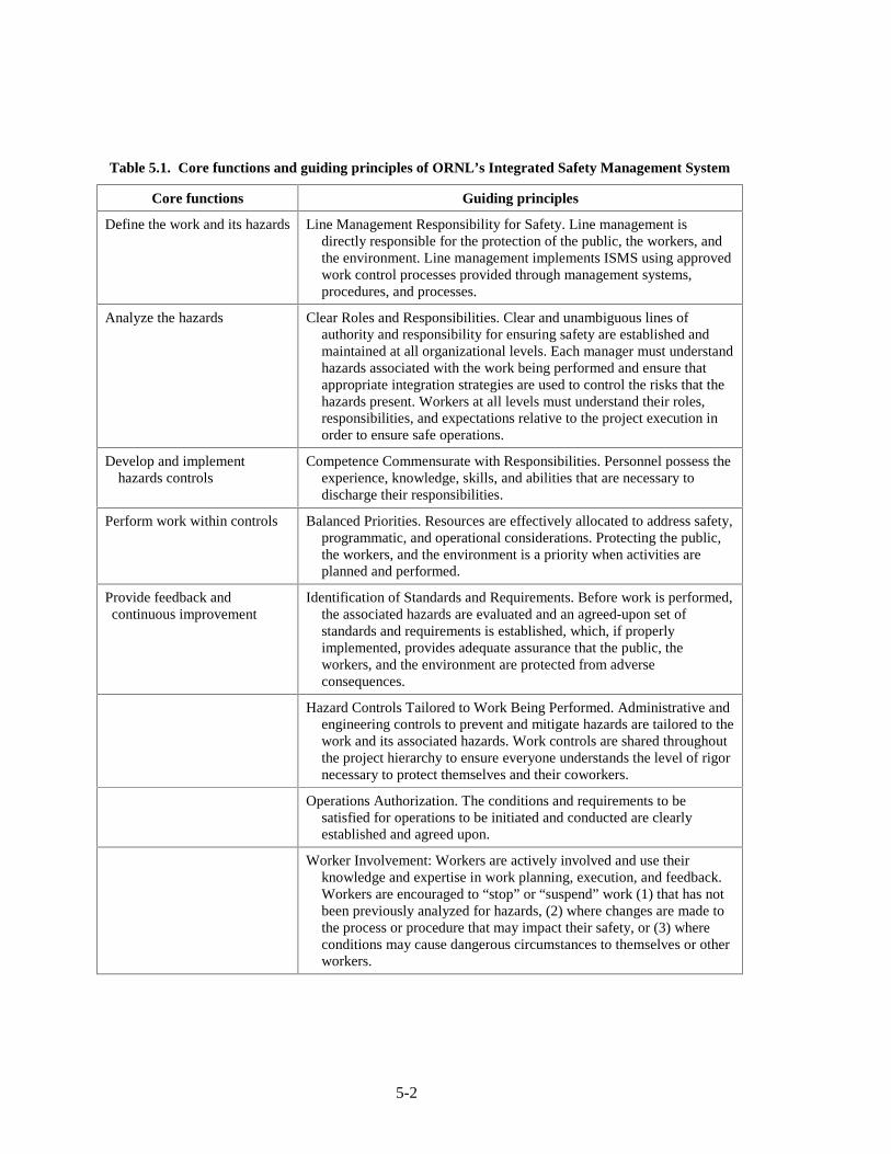
5-2
Table 5.1. Core functions and guiding principles of ORNL’s Integrated Safety Management System
Core functions Guiding principles
Define the work and its hazards Line Management Responsibility for Safety. Line management is directly responsible for the protection of the public, the workers, and the environment. Line management implements ISMS using approved work control processes provided through management systems, procedures, and processes.
Analyze the hazards Clear Roles and Responsibilities. Clear and unambiguous lines of authority and responsibility for ensuring safety are established and maintained at all organizational levels. Each manager must understand hazards associated with the work being performed and ensure that appropriate integration strategies are used to control the risks that the hazards present. Workers at all levels must understand their roles, responsibilities, and expectations relative to the project execution in order to ensure safe operations.
Develop and implement hazards controls
Competence Commensurate with Responsibilities. Personnel possess the experience, knowledge, skills, and abilities that are necessary to discharge their responsibilities.
Perform work within controls Balanced Priorities. Resources are effectively allocated to address safety, programmatic, and operational considerations. Protecting the public, the workers, and the environment is a priority when activities are planned and performed.
Provide feedback and continuous improvement
Identification of Standards and Requirements. Before work is performed, the associated hazards are evaluated and an agreed-upon set of standards and requirements is established, which, if properly implemented, provides adequate assurance that the public, the workers, and the environment are protected from adverse consequences.
Hazard Controls Tailored to Work Being Performed. Administrative and engineering controls to prevent and mitigate hazards are tailored to the work and its associated hazards. Work controls are shared throughout the project hierarchy to ensure everyone understands the level of rigor necessary to protect themselves and their coworkers.
Operations Authorization. The conditions and requirements to be satisfied for operations to be initiated and conducted are clearly established and agreed upon.
Worker Involvement: Workers are actively involved and use their knowledge and expertise in work planning, execution, and feedback. Workers are encouraged to “stop” or “suspend” work (1) that has not been previously analyzed for hazards, (2) where changes are made to the process or procedure that may impact their safety, or (3) where conditions may cause dangerous circumstances to themselves or other workers.

5-3
Table 5.2. Key Work Smart Standards potentially applicable to the Advanced Potassium Rankine Power Conversion System
10 CFR 1021, National Environmental Policy Act (NEPA) Implementation Procedures
29 CFR 1910, Occupational Safety & Health Standards
29 USCA 651 et seq, Occupational Safety & Health Act
40 CFR 50–90, CAA Implementing Regulations
40 CFR 170, Worker Protection Standard
40 CFR 311, Worker Protection
40 CFR 370, Hazardous Chemical Inventory Reporting Requirements
40 CFR 1500-1508, Council on Environmental Quality
42 USCA 4321 to 4370b, National Environmental Policy Act
42 USCA 7401 to 7671q, Clean Air Act and permits issued pursuant to
49 CFR 106-199, U.S. Department of Transportation (DOT) Hazardous Materials Regulations
7 CFR 372, National Environmental Policy Act Implementing Procedures
ANSI B30.20 (1993), Below-the-Hook Lifting Devices (design specification only)
ASME BPVC; Sections I, II, IV, V, VI, VII, VIII, IX, and X, American Society of Mechanical Engineers (ASME) Boiler and Pressure Vessel Code (for new construction and new purchases of pressure vessels) (the latest edition of the ASME BPVC is to be used; see ASME BPVC Foreword for specific applicability)
DOE O 420.1A; Attachment 2, Section 4.2, Facility Safety; Fire Protection, Compliance is in accordance with an Implementation Plan approved by DOE on June 19, 2003.
DOE O 440.1A; Attachment 2, Paragraph 15 (Fire Protection), Worker Protection Management for DOE Federal and Contractor Employees
DOE O 450.1, Environmental Protection Program
DOE O 460.1B, Packaging and Transportation Safety
DOE-STD-1090-2004, Hoisting and Rigging Standard (formerly Hoisting and Rigging Manual); Compliance is in accordance with an implementation plan submitted to DOE on 12/08/2004
National Electric Safety Code, as applicable as determined by the Authority Having Jurisdiction (AHJ)
National Fire Protection Association (NFPA) Standards (except NFPA 5000), as applicable as determined by the Authority Having Jurisdiction (AHJ)
National Fire Protection Association (NFPA) 70, as applicable as determined by the Authority Having Jurisdiction (AHJ)
National Fire Protection Association (NFPA) Life Safety Code, as applicable as determined by the Authority Having Jurisdiction (AHJ)
Tenn. Code Ann. 68-120-101 et seq, Fire Protection
Tenn. Code Ann. 68-201-101 et seq, Tennessee Air Quality Act and permits issued pursuant to
Tenn. R. & Reg. 1200-1-11, Hazardous Waste Management
Tenn. R. & Reg. 1200-1-7, Solid Waste Processing & Disposal
Source: Other Industrial, Radiological, and Non-Radiological Hazard Facilities (Approved 07-25-1996) through Rev./Change 43 (12-14-2004), ORNL Work Smart Standards, Standards Based Management System.

5-4
5.1.1.1 National Environmental Policy Act
The NEPA of 19691 was enacted by the U.S. Senate and House of Representatives to establish a national policy for the environment. The underlying intent of NEPA is to require federal agencies to incorporate environmental considerations into project development and decision-making processes. In addition, NEPA requires federal agencies to put this decision-making process into writing and make it open to public and judicial review. As a federal agency, the DOE and its prime contractors including UT-Battelle, LLC, must comply with NEPA.
To ensure that proposed actions, modifications to existing actions, and changes to existing facilities are screened by the ORNL NEPA Compliance Coordinator, principal investigators for experimental research projects are required to
• prepare a NEPA Action Review and Documentation Form, and • submit the completed form to the Compliance Coordinator for consideration. A procedure for implementing this process has been standardized by ORNL.2
At an early stage in the program, a NEPA Action Review and Documentation Form was completed and submitted in accordance with this procedure. Based on a review of the information provided on this form by the ORNL NEPA Coordinator and appropriate subject matter experts, the Advance Potassium Rankine Power Conversion System (Project No: 3227X) was granted a categorical exclusion (CX Cited: EA-1362, 3059X). In receiving the categorical exclusion, no further NEPA review and documentation are necessary. 5.1.1.2 Hazardous waste management
Potassium needed for potassium loop operations would be purchased from a chemical supplier and shipped to ORNL in accordance with Department of Transportation (DOT) regulations. At the end of testing, remaining potassium can either be
• transferred to a different ORNL chemical custodian, • reacted with water to produce aqueous potassium hydroxide, • shipped to an approved hazardous waste disposal company, or • returned to the original vendor.
During routine experimental activities involving potassium, no liquid or solid hazardous waste would be generated. Solid waste including personal protective equipment, fire extinguishing medium, and potassium reaction products generated as a result of a potassium leak or spill would be shipped to an approved hazardous waste disposal company. Requirements for disposal of these hazardous wastes involve characterizing, packaging, and certifying the waste to assure that it meets the acceptance criteria of the receiving organization. The total volume of solid waste is not expected to exceed 30 ft3.
As experimental operations progress, it would be necessary to periodically disassemble and reassemble the stainless steel piping system to remove and install test articles and heat transfer system components. Prior to disassembly, dry steam and argon would be carefully introduced into the piping system to remove residual potassium. The resulting potassium-water reaction rate is controlled by slowly adding steam to the flowing argon gas stream. During this operation, gaseous water vapor, hydrogen, and argon are released, and the aqueous potassium hydroxide that forms when the water reacts with the potassium is collected. The collected liquid would be transferred to another ORNL organization for acid neutralization as part of its waste minimization efforts. By implementing this procedure, no hazardous liquid waste is generated as a result of experimental activities.

5-5
5.1.1.3 Clean air compliance
Federal and state air pollution control regulations establish emission limitations for research activities conducted at ORNL facilities. Air emissions resulting from potassium loop operations involve the release of gaseous water vapor, hydrogen, and argon. Because these materials are not regulated by either federal or state regulatory authorities as air pollutants, release of these materials into the environment is permitted. 5.1.2 Worker Safety and Health
Applicable SBMS subject areas for ensuring a safe and healthy workplace include the following:
• Chemical Safety • Compressed Gas Cylinders and Related Systems • Electrical Work • Hazard Identification Signs and Tags: Interim Procedure • Hearing Conservation • Ladders • Lockout/Tagout • Occupational Hazard Controls • Personal Protective Equipment • Respiratory Protection • Stop Work and Restart Work: Imminent Danger Situations • Ventilation, Local Exhaust • Welding, Burning, and Hot Work
These subject areas focus on implementing industrial hygiene and occupational safety requirements. Applicable requirements associated with each of these subject areas are being used to guide the design of testing equipment and facilities and to establish operating practices and maintenance procedures for the potassium loop system. 5.1.3 Project Planning and Control
To help identify applicable hazards and appropriate control requirements for experimental work activities, ORNL has established a Research Hazard Analysis and Control System. This online project planning and control tool is used to generate a Research Safety Summary (RSS) that covers work activities, including experimental testing. In practice, screening is performed by answering questions pertaining to identified hazards and applicable subject areas. Based on answers to these questions, the tool provides a listing of potentially applicable controls and requirements for ensuring activity-specific safe work practices.
A draft RSS for this project (RSS Number 3141.0) was completed at an early stage of project planning to help identify possible hazards. Controls for these hazards are being factored into project planning and facility design considerations. Before loop operations, the draft RSS would be revised to reflect details of planned work practices and actual testing equipment performance characteristics. To ensure continued compliance with requirement changes, the RSS is authorized for one year and reviewed annually thereafter.

5-6
5.1.4 Engineering
The Engineering Management System supports ORNL research and development by focusing on safe and appropriate engineering standards integration into engineering design, modification, and operations. To ensure that potential fire hazards and applicable fire controls are identified, a Fire Hazard Analysis (FHA) was performed based on DOE guidance.3 Details about the content of the FHA are provided in Sect. 5.2.2.2. Conclusions and recommendations contained in the FHA have been used to revise the conceptual design for the potassium-testing apparatus and establish design requirements for the LMTF and its ventilation system. 5.2 ISMS IMPLEMENTATION
During the planning phase of the Advanced Potassium Rankine Power Conversion System project, initial efforts to implement the five core functions of ORNL’s ISMS involved
• identification of work and its hazards, • analysis of these hazards, and • development of hazard controls.
This work centered on preparing conceptual designs for the stainless steel piping system that serve as the primary pressure boundary for the confined potassium and the engineered barriers that protect workers from high-temperature alkali metal hazards. Remaining ISMS efforts involving implementing hazard controls, performing work within these controls, and providing feedback for continuous improvement would be addressed as part of the testing phase of the project. 5.2.1 HAZARD ANALYSIS
Two separate analyses were performed to define the fire protection and ES&H requirements
for controlling potentially hazardous potassium operations. Results of these analyses directly influence the design of engineered barriers and the implementation of management practices that affect worker safety and provide property and environmental protection. 5.2.1.1 Reaction products analysis
The objective of the reaction products analysis is to identify possible chemical reactions between potassium and moist air and to quantify the amount of each product generated by these reactions. Study findings indicate that the following chemical reactions can occur when potassium reacts with air and water.
4K + O2 → 2K2O (potassium oxide) 2K2O + O2 → 2K2O2 (potassium peroxide) 2K2O + 3O2 → 4KO2 (potassium superoxide) K + H2O → KOH + 1/2H2 (potassium hydroxide and hydrogen)

5-7
Potential hazards associated with each of these reaction products are summarized in Table 5.3. The amounts of each reaction product generated for each pound of potassium reacted are listed below.
• potassium oxide—[TBD] • potassium peroxide—[TBD] • potassium superoxide—[TBD] • potassium hydroxide—[TBD] • hydrogen—[TBD]
Table 5.3. Potential hazards for potassium and its reaction products
Chemical Potential hazard
Potassium (K) A silver with metallic luster solid (at room temperature) that is highly flammable and corrosive. Reacts violently with water and moist air, liberating and igniting flammable hydrogen gas, perhaps explosively. May catch fire if exposed to air or oxygen. Causes severe caustic and thermal burns to eyes and skin. Fumes may cause severe eye and respiratory tract irritation.
Potassium oxide (K2O) A crystalline solid that causes severe burns to mucous membranes and respiratory tract, skin, and eye burns.
Potassium peroxide (K2O2) A crystalline solid that is highly irritating to skin, eyes, and mucous membranes. Contact with moisture may produce heat and toxic fumes.
Potassium superoxide (KO2) An oxidizing corrosive solid that reacts violently with water generating oxygen, heat, and caustic potassium hydroxide solution. Some organics such as ethyl alcohol spontaneously combust on contact with potassium superoxide. May form explosive dust-air mixtures.
Potassium hydroxide (KOH) A water-reactive corrosive solid that is harmful if swallowed or contacted. Causes severe eye and skin burns. Causes severe digestive and respiratory tract burns.
Hydrogen (H2) A highly flammable gas that can burn with almost an invisible flame of low thermal radiation.
Operating practices and accident scenarios that could result in formation of these reaction
products include
• potassium leak during transfer of potassium from shipping container to sump tank • potassium leak due to failure of a primary pressure boundary component caused by
� thermal fatigue � weld or pipe defect � overstress condition � electrical arcing � physical damage and material degradation � metal loss due to corrosion, erosion, or cavitation
• potassium leak due to loss-of-argon cover gas • steam and argon injection during cleanup operations to remove residual potassium from
piping system components

5-8
To quantify the amount of hydrogen that could potentially be generated in the LMTF during a loss-of-potassium containment event, a hydrogen generation analysis was performed. Details of the analysis are presented in Appendix A. Analytical results confirm that the hydrogen concentration inside the LMTF cannot exceed a volumetric ratio of 0.76%. For this reason, it is not necessary to use explosion-proof electrical equipment inside the enclosure. Explosion-proof electrical equipment is only required when the volumetric ratio of hydrogen equals or exceeds 1%, which corresponds to 25% of the hydrogen lower flammability limit. 5.2.1.2 Fire hazard analysis
The purpose of a FHA is to comprehensively assess and document the risk from fire within individual fire areas in relation to existing or proposed fire protection. It involves identification of the fire risks, equipment present, engineered barriers and related materials of construction, fire protection systems, a determination of the adequacy of these systems, and a determination of the adequacy of the emergency egress systems. Concerns such as the life safety of building occupants and possible environmental damage from a fire incident are essential considerations in the analysis. The following topics are addressed in the FHA:4
• construction and facility use • fire protection • fire hazards • facility equipment/program preservation • life safety considerations • program documentation • operations and maintenance 5.2.2 Hazard Controls
Because alkali metals are both water reactive and pyrophoric, use of a combination of engineered barriers, administrative controls, and personal protective equipment (PPE) is required to support experimental activities while protecting the health and safety of research staff and avoiding property and environmental damage. 5.2.2.1 Engineered barriers
Key engineered barriers for controlling hazards include the potassium pressure confinement system (the loop itself), a splash shield, and an enclosure with a ventilation system. The functional requirements for these engineered barriers include
• confining the high-temperature potassium inside a welded stainless steel piping system with bellows (packless) valves,
• containing and collecting potassium leaks within a splash shield, • keeping water outside the LMTF, • keeping residue from potassium leaks inside the LMTF, • providing a 2-h fire rating (H-2 Occupancy) or meeting other alternate requirements,
and • supplying continuous ventilation air to remove heat, toxic gases, and solid reaction
products.
Design, construction, inspection, and testing requirements for the stainless steel piping system are provided in the codes and standards adopted by the American Society of Mechanical

5-9
Engineers (ASME) that are listed in Table 5.2. Additional requirements for the piping system are provided in the ASME Code for process piping.5 Fire protection engineering requirements are contained in the International Fire and Building Codes.6,7 Applicable standards for life safety issues and electrical work as well as standards for other relevant ES&H concerns are listed in Table 5.2.
Requirements for shipping containers used to transport potassium from the vendor to the point of use at ORNL are covered by applicable DOE standards and DOT regulations. Based on DOT regulations, potassium has the following hazardous material/dangerous goods classification:
• Proper Shipping Name: Potassium • Hazard Class: 4.3 • Packaging Group: I • Identification Number: UN2257 • Labels: Dangerous when wet
On-site transportation requirements for DOT Hazard Class 4.3 materials including potassium are contained in the ORNL on-site transportation safety document.8 According to these requirements, potassium containers can be transported on-site without special precautions or approved transportation procedures provided the containers are DOT approved and include the label shown in Fig. 3.4.
Additional requirements for engineered barriers and their applications would be provided in the ORNL approved RSS for this project and based on requirements contained in applicable SBMS subject area documents. 5.2.2.2 Administrative controls
Administrative control requirements are contained in applicable SBMS subject area documents identified in Sect. 5.1.2 and in the ORNL-approved RSS for the potassium loop project discussed in Sect. 5.1.3. For certain administrative controls, it may be necessary to conduct operations in accordance with approved step-by-step operating procedures, be properly trained or certified, or perform work using special tools or safety equipment.
Specific administrative controls that are required would be described in the ORNL-approved RSS for the project and based on requirements contained in applicable SBMS subject area documents. 5.2.2.3 Personal protective equipment
Protecting the skin, eyes, and respiratory systems of workers from the caustic effects of potassium reaction products requires the use of appropriate PPE. Key PPE that may be required during certain operations includes:
• self-contained breathing apparatus with full face piece operated in a positive-pressure mode, • chemical protective goggles with face shield attached to a hardhat equipped with fire-
retardant hood or hood liner, • dry leather gloves and boots, and • fire-retardant protective clothing.
Specific requirements for wearing and using PPE would be provided in the ORNL-approved RSS for the project and based on requirements contained in applicable SBMS subject area documents.

5-10
5.3 COMPRESSED-GAS CYLINDER STORAGE
Argon cover gas is used to prevent potassium from reacting with air and water. The argon is supplied by compressed-gas cylinders located outside the ventilated enclosure but inside Room D111. During storage and use, the cylinders are secured by belts or chains in the upright position. The cylinder valve cap is removed only when the cylinder is in use and would be tightly screwed in place during transport by an appropriate handcart or truck. Additional requirements for using, storing, and handling compressed-gas cylinders would be provided in the ORNL-approved RSS for the Advanced Potassium Rankine Power Conversion System project and based on requirements contained in applicable SBMS subject area documents. 5.4 EMERGENCY RESPONSE
In the event of an accidental potassium release, emergency response procedures may require covering the reaction products with dry soda ash, dry sodium chloride, or a proprietary material know as MET-L-X. Use of an NFPA Class D fire extinguisher may also be necessary. However, use of water or common dry chemical fire extinguishers to extinguish a potassium fire is not permitted. Postings will be used at dry chemical fire extinguisher locations to warn against their use during a potassium fire. Cleanup following a potassium release must involve removal and disposal of the reaction products. Requirements for cleanup operations would be provided in the ORNL-approved RSS for the project and based on requirements contained in applicable SBMS subject area documents. 5.5 MATERIAL REUSE AND HAZARDOUS WASTE DISPOSAL
When the project is completed, the testing hardware and piping system will be dismantled. Stainless steel materials and piping system components that cannot be used by other projects would be sent to salvage for recycle or sale.
Potassium that is drained from the piping system and any potassium remaining in inventory would either be (1) transferred to a different ORNL chemical custodian, (2) reacted with water to produce aqueous potassium hydroxide, or (3) shipped to an approved hazardous waste disposal company.
Disposal of aqueous potassium hydroxide is managed in accordance with policies and procedures established by the ORNL Environmental Protection & Waste Services Division as outlined in the Liquid & Gaseous Waste Treatment System Strategic Plan.9 Use of the aqueous potassium hydroxide for acid neutralization is anticipated as part of ORNL’s waste minimization operations. Consequently, no liquid effluent would be generated as a result of the proposed action.
Solid waste that may include PPE, used fire extinguishing medium, and potassium reactions products would be shipped to an approved hazardous waste disposal company operating under an existing ORNL subcontract. 5.6 REFERENCES
1. “National Environmental Policy Act,” Pub. L. 91-190, 42 U.S.C. 4321-4347, January 1, 1970, as amended by Pub. L. 94-52, July 3, 1975, Pub. L. 94-83, August 9, 1975, and Pub. L. 97-258, § 4(b), Sept. 13, 1982.
2. NEPA, Cultural Resources, and Related Environmental Document Generation, SOP-NEPA-01, Rev. 1, UT-Battelle, LLC, Oak Ridge, Tennessee, October 10, 2001.

5-11
3. “Fire Hazards Analysis for Building 9116 at Y-12 Plant, Oak Ridge, Tennessee,” prepared for the Department of Energy, March 1993.
4. “Liquid Metal Test Facility Preliminary Fire Hazard Analysis,” Fire Protection Engineering Internal Document, Oak Ridge National Laboratory, Oak Ridge, Tennessee, Rev. 0, May 6, 2005, Rev. 1, May 31, 2005.
5. “Process Piping,” ASME B31.3, American Society of Mechanical Engineers, New York, 2002.
6. “International Fire Code,” 2003 Edition, International Code Council, Falls Church, Virginia.
7. “International Building Code,” 2003 Edition, International Code Council, Falls Church, Virginia.
8. Oak Ridge National Laboratory On-Site Transportation Safety Document, ORNL/M-808, Revision 1, Oak Ridge National Laboratory, Oak Ridge, Tennessee, April 2003.
9. Van Hoesen, S. D. and Robinson, S. M. Oak Ridge National Laboratory Liquid & Gaseous Waste Treatment System Strategic Plan, ORNL/TM-2003/197, UT-Battelle, LLC, Oak Ridge, Tennessee, August 2003.

5-12

6-1
6. TEST FACILITY CONCEPTUAL DESIGN
High-temperature alkali metal testing for the Advanced Potassium Rankine Cycle Power Conversion System would be conducted in a specially designed test facility located in Building 5800, Room D111. Its primary purpose is to safely contain the potassium and potential potassium reaction products and thereby protect workers and the environment from potentially harmful potassium hazards. The test facility is a key element of the Space Reactor Technology Laboratory where a variety of potassium and lithium research and experimentation can be conducted.
The test facility includes three separate engineered barrier systems for containing the potassium and preventing it from adversely affecting humans and the natural environment during a possible loss-of-potassium containment event. These engineered barriers include the
1. potassium test loop, 2. splash shield and integral glove box, and 3. LMTF.
This defense-in-depth approach is considered an effective way to ensure facility safety because it builds in layers of protection against release of hazardous materials so that no one layer by itself, no matter how good, is completely relied upon. To compensate for potential human error and mechanical failure, these layers of protection with successive barriers minimize the potential for a release that could adversely affect the human or natural environment.1 Design considerations for the test facility focused on systematically addressing the various operational and safety requirements discussed in the previous chapters. 6.1 BUILDING 5800, ROOM D111
Building 5800 is a relatively new office and laboratory complex designed and constructed within the last 5 years. Figure 6.1 shows an aerial view of the main ORNL campus looking west with Building 5800 located near the bottom left side of the photograph. Although Building 5800 is part of the main ORNL campus, it is a privately owned building that is leased to the U.S. Department of Energy (DOE) for use by ORNL.2 UT-Battelle Development Corporation (UTBDC) is the building owner. From a fire protection engineering and building code compliance viewpoint, the City of Oak Ridge, Tennessee, is the Authority Having Jurisdiction (AHJ) for Building 5800.
Room D111 is located on the ground floor of Building 5800 and occupies about 5,000 ft2 of floor area. The floor is epoxy-coated reinforced concrete capable of supporting 150 lb/ft2 of live load. Access for moving materials and components into Room D111 is through a 10-ft by 10-ft rollup door and a 3-ft wide passage door located on the east end of the room. The roof for Room D111 is supported by steel trusses that are located at least 25 ft above the top surface of the floor slab and is capable of safely supporting a live load of 20 lb/ft2. Electrical power panels are located on the north wall of the room. Fire protection for Room D111 is provided by an automatic sprinkler system with sprinkler heads located near the ceiling
From a fire protection engineering viewpoint, Building 5800 is rated for Business Occupancy based on International Fire Code3 rules. This particular rating limits the amount of water-reactive and pyrophoric materials such as potassium that may be used in the building to no more than 4 lb of material in storage and no more than 1 lb of material in use. Because the test loop may require up to 100 lb of potassium, a Preliminary Fire Hazard Analysis was performed to identify applicable International Fire and Building Code3,4 requirements and to define appropriate engineered barriers and administrative controls that, if implemented, would allow the use of these materials in Building 5800.

F
ig. 6
.1.
Aer
ial v
iew
of
Oak
Rid
ge N
atio
nal L
abor
ator
y m
ain
cam
pus.
Bui
ldin
g 58
00
6-2

6-3
Specific hazards and fire protection requirements that were considered in developing conceptual designs for the test facility are discussed in the Preliminary Fire Hazard Analysis5 and the Hydrogen Generation Analysis presented in Appendix A. These documents represent a consensus between ORNL project, safety, and fire protection engineering staff as well as the AHJ for Building 5800. One of the main objectives of the Preliminary Fire Hazard Analysis was to resolve contradictory rules and requirements contained in the 2003 editions of the International Fire and Building Codes and other referenced documents. 6.2 POTASSIUM TEST LOOP
Based on the design requirements for the various operating modes described in Sects. 2 and 3, and the design calculations presented in Sect. 7, along with the addition of some conservative factors, general loop mechanical design criteria were developed and presented in Table 6.1.
Table 6.1. General loop fluid criteria
Mode Temperature
(K) Pressure
(kPa) Flow rate
(kg/s) Pump head
(kPa) Pump temperature
(K)
Normal operating conditions
Single phase 750 1600 0.113 1450a 750
Two phase 1000 150 0.01 25 875
Design conditions
Single phase 750 1800 0.2 1500a 750
Two phase 1000 788 0.02 200 875
aA pressure drop across the materials tester of 1400 kPa was assumed for both normal and design conditions.
The potassium test loop shown in Fig. 6.2 is an engineered barrier that is designed to confine and circulate up to 100 lb of potassium. This piping configuration was developed to satisfy the testing requirements and operating objectives discussed in Sect. 3.1 and includes the following components that are welded together to create a leaktight pressure boundary for potassium:
• sump tank • boiler • expansion tank • test fixture • condenser • pump • flowmeters • hot trap • plugging indicator • cooler • valves • stainless steel pipe and welded fittings (3/4-in., schedule 40, type 316L)
Three different operating modes are possible with this piping configuration. They include
single-phase thermal-hydraulic tests, single-phase bearing and seal tests, and two-phase boiler

6-4
Fig. 6.2. Potassium test loop conceptual design.
and condensing tests. Valve alignments for each of these operating modes are provided in Table 6.2. For operations involving the transfer of potassium to and from the sump tank, stop valves V1, V2, and V3 are aligned as follows.
• When potassium is being transferred from a metal shipping container to the sump tank, stop valve V1 is opened, and stop valves V2 and V3 are closed.
• When potassium is being discharged from the sump tank, stop valve V3 is opened, and stop valves V1 and V2 are closed.
Table 6.2. Valve alignment operating mode schedule
(See Fig. 6.2 for valve locations)
Single-phase flow testing Two-phase flow testing Stop valve
(see Fig. 6.2) Thermal-hydraulic tests
Wear and bearing tests
Boiling and condensing tests
V1 Closed Closed Closed V2 Open Open Open V3 Closed Closed Closed V4 Open Open Closed V5 Open Closed Open V6 Closed Open Closed V7 Closed Open Closed
Test loop charging is accomplished by heating the sump tank and the piping system to at
least 250°F, opening stop valve V2, and then applying argon cover gas pressure to the sump tank.
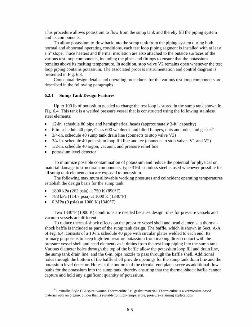
6-5
This procedure allows potassium to flow from the sump tank and thereby fill the piping system and its components.
To allow potassium to flow back into the sump tank from the piping system during both normal and abnormal operating conditions, each test loop piping segment is installed with at least a 5° slope. Trace heaters and thermal insulation are also attached to the outside surfaces of the various test loop components, including the pipes and fittings to ensure that the potassium remains above its melting temperature. In addition, stop valve V2 remains open whenever the test loop piping contains potassium. The associated process instrumentation and control diagram is presented in Fig. 6.3.
Conceptual design details and operating procedures for the various test loop components are described in the following paragraphs. 6.2.1 Sump Tank Design Features
Up to 100 lb of potassium needed to charge the test loop is stored in the sump tank shown in Fig. 6.4. This tank is a welded pressure vessel that is constructed using the following stainless steel elements:
• 12-in. schedule 80 pipe and hemispherical heads (approximately 3-ft3 capacity) • 6-in. schedule 40 pipe, Class 600 weldneck and blind flanges, nuts and bolts, and gasket* • 3/4-in. schedule 40 sump tank drain line (connects to stop valve V3) • 3/4-in. schedule 40 potassium loop fill line and tee (connects to stop valves V1 and V2) • 1/2-in. schedule 40 argon, vacuum, and pressure relief line • potassium level detector
To minimize possible contamination of potassium and reduce the potential for physical or material damage to structural components, type 316L stainless steel is used whenever possible for all sump tank elements that are exposed to potassium.
The following maximum allowable working pressures and coincident operating temperatures establish the design basis for the sump tank:
• 1800 kPa (262 psia) at 750 K (890°F) • 788 kPa (114.7 psia) at 1000 K (1340°F) • 0 MPa (0 psia) at 1000 K (1340°F)
Two 1340°F (1000 K) conditions are needed because design rules for pressure vessels and vacuum vessels are different.
To reduce thermal-shock effects on the pressure vessel shell and head elements, a thermal-shock baffle is included as part of the sump tank design. The baffle, which is shown in Sect. A-A of Fig. 6.4, consists of a 10-in. schedule 40 pipe with circular plates welded to each end. Its primary purpose is to keep high-temperature potassium from making direct contact with the pressure vessel shell and head elements as it drains from the test loop piping into the sump tank. Various diameter holes through the top of the baffle allow the potassium loop fill and drain line, the sump tank drain line, and the 6-in. pipe nozzle to pass through the baffle shell. Additional holes through the bottom of the baffle shell provide openings for the sump tank drain line and the potassium level detector. Holes at the bottoms of the circular end plates serve as additional flow paths for the potassium into the sump tank, thereby ensuring that the thermal-shock baffle cannot capture and hold any significant quantity of potassium.
*Flexitallic Style CGI spiral wound Thermiculite 815 gasket material. Thermiculite is a vermiculite-based
material with an organic binder that is suitable for high-temperature, pressure-retaining applications.
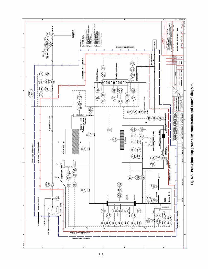
6-6
Fig
. 6.3
. P
otas
sium
loop
pro
cess
inst
rum
enta
tion
and
con
trol
dia
gram
.

6-7
Fig. 6.4. Sump tank conceptual design.
The sump tank drain line extends through a hole in the bottom of the sump tank and
terminates inside a pipe cap that is welded to the bottom surface of the 12-in. schedule 80 pipe shell. This pipe cap serves as a collection point for potassium when the sump tank is drained. Its use for this purpose also helps minimize the amount of potassium that remains inside the sump tank when the draining process is finished.
A weldneck and blind flange assembly is included in the sump tank design to provide a means for installing and removing getter material needed to purify the potassium. The getter material consists of relatively thin sheets of zirconium separated by a gap as shown in Fig. 6.5. These getter assemblies can be installed inside the sump tank through the weldneck flange and 6-in. pipe subassembly that is welded to the top of the tank. The blind flange that closes the weldneck flange includes two features: (1) a 1/2-in. schedule 40 pipe that serves as an argon, vacuum, and pressure relief line and (2) a potassium level detector assembly. Twelve nuts and bolts are used to connect the blind flange to the weldneck flange while the joint between the flanges is sealed by a spiral-wound gasket. This gasket is a vermiculite-based material with an organic binder that creates a leaktight seal. Inner and outer stainless steel backup rings maintain the integrity of the vermiculite while under pressure.
Vermiculite is well suited for high-temperature sealing applications, but the organic binder degrades when exposed to high temperatures. For this reason, these gaskets are not reusable and must be replaced before the blind flange is reinstalled. Potential problems associated with exposure of the organic binder to potassium are eliminated because the level of potassium in the sump tank always remains below the level of the gasket, and the sump tank is always provided with argon cover gas when potassium is present.
The potassium level detector is an electrical resistance sensor that immerses in the potassium and provides a means for determining the potassium depth inside the sump tank. Wires from the level detector connect to instrumentation that is capable of converting the indicated voltage signal to the location of the potassium surface. Details of the level detector design and the associated electrical circuit for sensing potassium level are shown in Fig. 6.6. Precise calibration of the level

F
ig. 6
.5.
Get
ter
asse
mbl
y co
ncep
tual
des
ign.
6-8

6-9
Fig. 6.6. Potassium level detector and instrumentation
schematic. (Source: R. D. Brooks, Alkali Metals Boiling and Condensing Investigations, Vol. 1, NASA CR-54050, June 1964).

6-10
detector is necessary so that the position of the potassium surface relative to the bottom of the sump tank can be determined and then used to indicate the amount of potassium that is present in the sump tank.
Overpressure protection for the sump tank is provided by a self-closing pressure relief valve located in the argon cover gas system piping. For all operating conditions, the sump tank is protected by a primary pressure relief device with a set pressure no greater than 272 psia. During sump tank charging operations when potassium is being transferred from a metal storage container to the sump tank, a secondary pressure relief device with a set pressure no more than 15 psig is installed in parallel with the primary pressure relief device to ensure that the metal storage tank does not exceed its maximum allowable working pressure. A separate secondary pressure relief device may be installed in parallel with the primary pressure relief device when the bearing and seal test fixture is operating. Its set pressure depends on the specified maximum allowable working pressure for the test fixture and the position of the test fixture relative to the sump tank. Pressure relief discharge piping is directed to a cold trap capable of condensing potassium vapors that might be released along with the argon cover gas.
A method for independently heating the sump tank to temperatures up to 1200°F (922 K) would be developed during the design phase of the project. The method selected involves either construction of an electrically heated enclosure that surrounds the sump tank or attachment of trace heaters and thermal insulation to the outer shell and head surfaces of the sump tank. This heating system would be used to maintain the temperature of the potassium inside the sump tank at a specified level and for a specified time to allow the getter material to remove oxygen from the potassium. It also is used to heat the potassium to a molten state for test loop charging and to maintain the temperature of the potassium above its melting point during normal operations.
Structural support for the sump tank is provided to prevent movement of the tank relative to the connected piping. The method used to anchor the sump tank to the floor of the splash shield depends on the design details of the sump tank heating system and the type and thickness of thermal insulation used to isolate the sump tank supports from the splash shield. These details would be established during the final design phase of the project. 6.2.2 Boiler Design Features
The boiler serves as the primary heat source for increasing the temperature of the potassium to the required test conditions. Ideal conditions for the boiler simulation tests would have been those associated with a single tube of the boiler bundle design developed for the reference Rankine cycle power conversion system during Phase I of the project, indicated as Option 0 in Table 6.3. A secondary function would have been served by operation, for validation purposes, near the conditions of relevant previous tests by Peterson as indicated in Option 8 below. Other experimental and project constraints (sonic limits, insulated electrical resistance heater limits, size limits, cost limits, power limits, etc.) served to bound available testing options.
Unfortunately, neither the 1300 K operating temperature specified in Phase I nor the 1116 K operating temperature of Peterson was achievable using materials available within project funding limits. As a compromise, 1000 K was selected as the maximum operating temperature, allowing the use of stainless steel construction materials for the loop. Primarily due to the large ratio of the saturated vapor densities (approximately ten as presented in the Table 6.3) at these two temperatures, it is not possible to match all the relevant operating parameters presented in the Phase I design.
Based on scaling considerations, it was judged most important to attempt to approximate vapor Reynolds and Mach numbers for the boiler. If vapor Mach number matching could not be achieved, the desire was to limit vapor Mach numbers to values substantially less than unity (suggested 0.3 maximum) to reduce the importance of compressibility effects.

Tab
le 6
.3.
Boi
ler
para
met
er o
ptio
ns
(Opt
ion
O c
orre
spon
ds to
Pha
se I
des
ign
cond
ition
s. N
umbe
rs in
bol
d m
atch
thos
e co
nditi
ons)
Opt
ion
0 1
2 3
4 5
6 7
8 U
nits
Tem
pera
ture
13
00
1000
10
00
1000
10
00
1000
10
00
1000
11
16
K
Mas
s fl
ow
0.02
27
0.15
53
0.02
27
0.02
27
0.00
20
0.02
27
0.01
74
0.01
00
0.03
80
kg/s
In
side
dia
met
er
10.0
89
.1
10.0
34
.1
10.0
13
.0
10.0
15
.8
17.0
m
m
Hea
t loa
d 47
.4
325
47.4
47
.4
4.08
47
.4
36.4
20
.9
71.0
kW
L
engt
h 2.
40
2.40
2.
40
2.40
2.
40
2.40
2.
40
2.40
2.
32
m
Hea
t tra
nsfe
r ar
ea
0.07
54
0.67
18
0.07
54
0.25
71
0.07
54
0.09
80
0.07
54
0.11
91
0.12
43
m2
Hea
t flu
x 62
9 48
3 62
9 18
4 54
48
4 48
3 17
6 57
1 kW
/m2
Flow
are
a 7.
85E
-05
6.24
E-0
3 7.
85E
-05
9.13
E-0
4 7.
85E
-05
1.33
E-0
4 7.
85E
-05
1.96
E-0
4 2.
27E
-04
m2
Wet
ted
peri
met
er
31.4
27
9.9
31.4
10
7.1
31.4
40
.8
31.4
49
.6
53.5
m
m
Liq
uid
dens
ity
598
672
672
672
672
672
672
672
647
kg/m
3
Liq
uid
volu
me
flow
3.
79E
-05
2.31
E-0
4 3.
37E
-05
3.37
E-0
5 2.
90E
-06
3.37
E-0
5 2.
59E
-05
1.49
E-0
5 5.
87E
-05
m3 /
s L
iqui
d ve
loci
ty
0.48
3 0.
037
0.42
9 0.
037
0.03
7 0.
254
0.33
0 0.
076
0.25
8 m
/s
Liq
uid
Rey
nold
s nu
mbe
r 27
486
1643
7 21
378
6269
18
39
1644
4 16
439
5969
23
114
Vap
or d
ensi
ty
3.81
2 0.
372
0.37
2 0.
372
0.37
2 0.
372
0.37
2 0.
372
0.87
5 kg
/m3
Vap
or v
olum
e fl
ow
5.95
E-0
3 4.
18E
-01
6.10
E-0
2 6.
10E
-02
5.25
E-0
3 6.
10E
-02
4.69
E-0
2 2.
69E
-02
4.34
E-0
2 m
3 /s
Vap
or v
eloc
ity
76
67
777
67
67
460
597
137
191
m/s
V
apor
son
ic v
eloc
ity
600
531
531
531
531
531
531
531
554
m/s
V
apor
Rey
nold
s nu
mbe
r 1.
36E
+05
1.36
E+0
5 1.
77E
+05
5.19
E+
04
1.52
E+
04
1.36
E+0
5 1.
36E
+05
4.94
E+0
4 1.
60E
+05
V
apor
Mac
h nu
mbe
r 0.
126
0.12
6 1.
464
0.12
6 0.
126
0.86
6 1.
126
0.25
9 0.
344
6-11

6-12
Option 1 in Table 6.3 presents the parameter combination for 1000 K that scales to the 1300 K reference Rankine cycle power conversion system boiler tube vapor Reynolds and Mach numbers (although other parameters are not matched). Unfortunately, the heat load and inside diameter (325 kW and 89.1 mm, respectively) were deemed excessive for Phase II efforts. If the reference boiler design mass flow, inside diameter, and heat load were retained, but operated at 1000 K instead of 1300 K, Option 2 results are implied. For this case, moderate heat load and inside diameter requirements are indicated and the vapor Reynolds number is approximated, but, because of the relatively low vapor density, the vapor Mach number exceeds unity—an unrealistic situation for Phase II testing. For Option 3, the inside diameter was increased to drop the vapor Mach number to the reference boiler design value, but the resulting vapor Reynolds number was somewhat below that of the Phase I design value. Another way of matching the reference design vapor Mach number is to employ that design’s inside diameter, but decrease the mass flow and heat load as shown for Option 4. However, this combination gives a vapor Reynolds number much more removed from the reference value.
Options 5 and 6 represent two attempts at matching the reference design’s vapor Reynolds number. In the first case, the mass flow and heat load are retained, while the inside diameter was increased above the reference design’s value enough to match the vapor Reynolds number—resulting in an impractically high vapor Mach number (very near unity for Option 5). The second case retained the reference inside diameter, while reducing the mass flow and heat load to match the reference vapor Reynolds number, resulting in a vapor Mach number exceeding unity—an experimental impossibility within project constraints.
The final combination (Option 7) examined here employed a standard dimension tube (1/2-in. schedule 40 stainless steel) that approximated that employed by Peterson. Mass flow and heat load were selected as a compromise of matching the reference design vapor Mach and Reynolds numbers. The result gave a vapor Reynolds number somewhat below those of the reference boiler design selected and Peterson (but still well turbulent) and a vapor Mach number somewhat above the reference value, but approximating the Peterson value (and below the estimated compressibility effect limit). This option was judged to offer the best compromise among the conflicting desires and constraints indicated above.
Based on this assessment, a 1/2-in. schedule 40 type 316L stainless steel pipe was chosen for boiler construction. The length of the heated section is 95 in. (2.4 m). Other boiler elements include thermal insulation, temperature sensors, and end fittings that permit welding of the boiler to the 3/4-in. piping system. To reduce piping stresses resulting from thermal expansion, the boiler is supported in a manner that allows almost unrestricted vertical and horizontal movement. Increasing the boiler temperature from room temperature to 1000 K (1340°F) changes its length by about 1.3 in. If this movement is not permitted, the 1/2-in. pipe would buckle or distort, thereby adversely affecting the boiler’s thermal performance, structural capacity, or leaktight integrity. Support locations for the boiler are to be identified during the final design phase of the project. 6.2.3 Expansion Tank Design Features
The conceptual design includes a type 316L stainless steel pressure vessel installed upstream from the test fixture at the location shown in Fig. 6.2 to serve as an expansion tank during single-phase testing. Its dimensions and capacity depend on the amount of potassium in the test loop piping and the temperature of the potassium. During two-phase testing stop valves V4 and V7 are closed, thereby isolating the expansion tank from the remainder of the test loop because the expansion tank is not needed for the boiling and condensing tests.
The design of the expansion tank includes an upper nozzle for connecting argon cover gas, a lower nozzle for attaching the potassium test loop piping, and a potassium level detector for determining the potassium surface level inside the expansion tank. Maximum allowable working

6-13
pressure and coincident operating temperatures for designing the expansion tank are the same as those for the sump tank. Depending on its size, the expansion tank may not require an ASME Code Stamp. However, the expansion tank is be designed to comply with the intent of the ASME Boiler and Pressure Code rules contained in Section VIII, Division 1.6 Trace heaters and thermal insulation are installed on the outside of the expansion tank to maintain the potassium at the required operating temperature.
During final design of the test loop piping system, the center of the expansion tank should be positioned at approximately the same elevation as the maximum liquid level in the text fixture. In addition, argon cover gas piping is included in the design to connect the expansion tank to the test fixture. This piping configuration ensures that the potassium level in the test fixture is at the same elevation as the potassium level in the expansion tank. Through these design features, it is possible to determine the position of the potassium surface inside the test fixture using data provided by the level detector located inside the expansion tank.
The argon cover gas piping system that is connected to the expansion tank includes at least one self-closing pressure relief devices capable of providing overpressure protection for the expansion tank. Although the exact set pressures for these devices depend on the operating conditions which depend on the specific tests being conducted, the expansion tank is always protected by a pressure relief device with a set pressure that is no greater than 273 psia. 6.2.4 Wear and Bearing Test Fixture Design Features
The conceptual design of the wear and bearing test fixture is shown in Fig. 6.7. Its four main parts are the motor and spindle assembly, spindle support, support plate, and containment vessel. These parts bolt together to create a test fixture for characterizing the properties and performance
Fig. 6.7. Wear and bearing test fixture conceptual design.

6-14
of test articles in a high-temperature liquid potassium environment. Key design features for this 237-kg (523-lb) test fixture include
• pressure range: 0.1 psia to 15 psig, • temperature limit: 800°F (700 K) maximum, • potassium flow rate: 0.05 lb/s (design point), • recommended motor environment temperature range: ambient to 322 K (120°F), and
spindle rotational speed: 0 to 10,000 rpm (variable). In operation, the test articles are continuously immersed in a pool of liquid potassium that is
created by a two-chambered containment vessel. As Fig. 6.7 shows, the wear and bearing tester that holds and manipulates the test articles is located within the inner chamber of the containment vessel. Prior to testing, potassium flow through the opening in the bottom of the containment vessel is initiated. This flow keeps the inner chamber of the containment vessel full of potassium. Excess potassium that flows into the containment vessel spills over the cylindrical wall of the inner chamber and flows into the surrounding annulus.
As the test progresses, potassium drains out of the annulus, passes into a separator located beneath the containment vessel, and then flows back to the pump. Heat required to maintain the temperature of potassium in the containment vessel is provided by the boiler and trace heaters located on the piping that connects the boiler to the containment vessel. The temperature of the potassium inside the containment vessel is maintained by trace heaters and thermal insulation installed on the outside of the containment vessel and around the support plate.
To ensure that the proper amount of potassium flows into the containment vessel, the potassium level in the containment vessel is independently measured by a level detector located in the expansion tank described in Sect. 6.2.3. An argon line connects the expansion tank and the containment vessel, thereby equalizing the pressure in these two vessels and ensuring that both potassium surfaces are at essentially the same elevation. A self-closing pressure relief device with a set pressure of 15 psig or less is installed in the argon line to provide overpressure protection for the expansion tank and the test fixture.
After the required potassium level, flow, and temperature conditions are established, the motor is energized causing the spindle to rotate. Testing occurs as the test articles are manipulated by the wear and bearing tester and its rotating parts. At the completion of each test, the motor and spindle assembly, spindle support, and support plate are disassembled so the test articles can be removed for cleaning and examination. After all wear and bearing tests are completed, the motor and spindle assembly, spindle support, and support plate are removed and a blind flange installed to seal the containment vessel. In this configuration, the test article is isolated from the remainder of the test loop by closing stop valves V6 and V7 shown in Fig. 6.2, disconnecting the argon line that connects the expansion tank to the test fixture, and applying argon cover gas to the containment vessel. A self-closing pressure relief device with a set pressure of 15 psig or less is included in the argon cover gas piping to provide overpressure protection for the containment vessel.
When the containment vessel is welded to the connecting piping, it should be located at the very highest elevation of the potassium test loop with the top flange of the containment vessel even with the top of the splash shield. From this elevation, potassium can drain freely from both chambers of the containment vessel and into the sump tank.
Because the spindle has a relatively low operating temperature limit, the design locates the motor and spindle assembly above the splash shield inside a dual-purpose enclosure (described in more detail in Sect. 6.3 and shown in Fig. 6.10) positioned on top of the splash shield. During wear and bearing tests, an electric fan (separate from the LMTF ventilation system) draws air through the enclosure to maintain an acceptable temperature range for the motor and spindle assembly. In this operating mode, intake air from the LMTF flows through openings in the walls of the enclosure.

6-15
After each wear and bearing test, the enclosure is reconfigured to function as a glove box. This glove box receives an argon purge and would be properly equipped for safely performing test fixture disassembling and reassembly operations. A three-axis dovetail slide such as the one shown in Fig 6.8 would be installed inside the glove box and used to lift and move the 97-kg (213-lb) motor and spindle. With this assembly removed, it is possible to manually lift the support plate from the containment vessel and thereby provide access to the wear and bearing test articles. Additional information about the splash shield and glove box is presented in Sect. 6.3.
Structural support for the test fixture is provided to prevent movement of the containment vessel relative to the connected piping. The method used to attach the bottom of the containment vessel to structural steel framing depends on the final design details of the test fixture and its insulation and heating systems as well as the splash shield design. These details would be finalized during the design phase of the project.
A more complete description of the wear and bearing test fixture design can be found in a separate report.7 6.2.5 Separator Design Features
After potassium flows out of the containment vessel, it flows into the separator located between the test fixture and the condenser as shown in Fig. 6.2. The separator is a 2- to 3-in.-diam pressure vessel that provides a space for the argon cover gas to separate from the potassium. Trace heaters located on the outer surface of the separator provide a means for controlling the temperature of the potassium in the separator.
A potassium level detector inside the separator provides a feedback signal that the sump tank argon cover gas system uses to regulate the potassium inventory in the test loop during wear and bearing tests. The exact size and configuration of the separator, potassium level detector, and trace heaters would be established during the final design phase of the project. 6.2.6 Condenser Design Features
A condenser serves as the primary means for removing excess heat from the potassium that circulates through the test loop. This potassium-to-air heat exchanger consists of about 120 in. of 3/4-in. stainless steel pipe that is fabricated into a coil. The coil is housed inside an insulated metal enclosure that is supplied with cooling air by an electrical fan and associated ductwork. This ductwork includes an electrical heater that is capable of increasing the temperature of the cooling air and thereby controlling the rate of cooling. Exhaust ductwork is also connected to the insulated metal splash shield and used to direct the heated air out of the splash shield and into the LMTF for discharge outside by the LMTF ventilation system.
The condenser coil is welded to the test loop piping and supported by hangars that allow both horizontal and vertical movement. Allowing the condenser coil to move reduces pipe stresses resulting from differential thermal expansion.
6.2.7 Pump Design Features
The pump is an electromagnetic device capable of circulating high-temperature potassium through the test loop piping during both single-phase and two-phase testing. Flow and pressure characteristics that serve as the basis for its design are discussed in Sect. 3.1.1.4.
Structural support for the pump is provided to prevent movement of the pump relative to the connected piping. The method used to anchor the pump depends on the design configuration of the pump, its weight and dynamic characteristics, it elevation relative to the sump tank, and the type and thickness of thermal insulation used to isolate the pump housing from the steel beams

F
ig. 6
.8.
Thr
ee-a
xis
dove
tail
slid
e.
6-16

6-17
and columns that provide structural support for the pump. These structural details would be finalized during the final design phase of the project. 6.2.8 Flowmeter Design Features
Two flowmeters are included in the test loop piping system to measure potassium flow rates at separate locations. One flowmeter is located between the condenser and the pump. Its purpose is to measure the flow rate of potassium that circulates through the test loop. The other flowmeter is located in the plugging indicator bypass loop. Its purpose is discussed in Sect. 6.2.10.
The flowmeters are electromagnetic devices that are capable of measuring potassium flow rates at high temperatures. Selection of a flowmeter design would occur during the final design phase of the project. 6.2.9 Hot Trap Design Features
A hot trap is included in the test loop to remove contaminants from the potassium. It is located in a bypass loop around the pump as shown in Fig. 6.2.
The hot trap is designed as a pressure vessel and includes upper and lower nozzles for attaching the hot trap to the potassium test loop piping. Zirconium sheets are placed inside the hot trap during construction. These sheets function as the getter. Depending on its size, the intent of the hot trap may not require an ASME Code Stamp. However, the hot trap is designed to comply with ASME Boiler and Pressure Code rules contained in Section VIII, Division 1.6 Overpressure protection for the hot trap is provided by pressure relief devices installed as part of the sump tank argon piping system. 6.2.10 Plugging Indicator Design Features
A plugging indicator is located in a bypass loop around the pump as shown in Fig. 6.2. Its purpose is to provide a qualitative indication of the level of potassium contamination. In operation, the plugging indicator functions as an orifice. When the level of contamination is low, potassium flows through the orifice, but when the level of contamination is high, the orifice clogs and functions as a stop valve. Potassium flow is determined by a flowmeter located upstream of the plugging indicator. A potassium-to-air heat exchanger known as a cooler is located upstream of the plugging indicator. Its purpose is to reduce the temperature of the potassium that flows through the plugging indicator. By knowing the temperature of the potassium when plugging occurs, and the oxide saturation limits as a function of temperature, it is possible to estimate the level of potassium contamination that is present in the test loop. Features of the flowmeter and cooler are provided in Sects. 6.2.8 and 6.2.11, respectively.
To ensure that potassium can drain from all parts of the test loop, the plugging indicator is located at the highest elevation in the bypass loop. These piping details and selection of an appropriate size orifice for the plugging indicator would be made during the final design phase of the project. Overpressure protection for the plugging indicator is provided by pressure relief devices installed as part of the sump tank argon piping system. 6.2.11 Cooler Design Features
The plugging indicator bypass loop around the pump includes a potassium-to-air heat exchanger to reduce and control the temperature of potassium that flows into the plugging indicator. Elements of the cooler include a coil of stainless steel piping located inside an insulated metal enclosure, ductwork, fan, and heater. Cooling air is supplied to the insulated metal enclosure through ductwork that is connected to an electric fan located outside of the splash

6-18
shield but inside the LMTF. An electric heater is included in the ductwork to provide a means for controlling the temperature of the air that is supplied to the insulated metal enclosure. Exhaust ductwork connected to the insulated metal splash shield connects to the exhaust ductwork for the main loop condenser. Ductwork and insulated metal enclosure details, fan size, and heater capacity would be established during the final design phase of the project. 6.2.12 Valve Design Features
Seven manually operated 3/4-in. nominal size stop valves are used to control flow in the potassium test loop. Each valve has a stainless steel body and formed bellows seals suitable for operating in a potassium environment at temperatures up to 1340°F (1000 K).
The valves are welded to the adjacent piping at the locations shown in Fig. 6.2. When installed in the test loop piping system, the valves are oriented in a position that permits optimum draining of potassium. To reduce chances of damaging the bellows seals, the valves would not be opened or closed unless the surface temperature of the valve body is at least 250°F (394 K). In service, each valve is operated either completely open or completely closed. The valves do not provide flow control. Table 6.2 provides the alignment schedule for the seven valves. 6.2.13 Piping System Design Features
The potassium test loop components are connected by 3/4-in., schedule 40, type 316L stainless steel pipe and fittings using welded joints. In designing the piping system, consideration must be given to optimizing the locations of component and piping supports to minimize bending stresses resulting from differential thermal expansion. Structural stability for the test loop is established by physically securing the sump tank, pump, and test fixture in space, thereby preventing vertical and horizontal movement as well as rotation of these key test loop components. All other test loop components and piping are supported in ways that do not significantly inhibit expansion and contraction by allowing relative movement between these three fixed objects. Piping system flexibility is achieved by varying the lengths and configurations of the individual piping segments. During the final design process, emphasis would be placed on minimizing the total length of pipe in the system and reducing the complexity of the various piping segment configurations. Both of these design considerations have a direct impact on potassium inventory and the overall dimensions of the splash shield. After the test loop configuration is finalized, a stress analysis of the piping system would be performed. Results of the analysis would be used to verify compliance with rules contained in the ASME Code for process piping.8 The test loop conceptual design shown in Fig. 6.2 was developed to serve as a starting point for this design process.
To ensure that potassium remains liquid at all times while the test loop is charged, each component and piping segment includes trace heaters as part of its design. These heaters are capable of independently regulating and maintaining the potassium temperature within a particular zone.
Thermal insulation is used extensively to reduce heat losses from the piping system. If the maximum operating temperature is 1200°F (922 K) or less, molded blocks of calcium silicate insulation can be applied directly to component and pipe surfaces and then wrapped with a stainless steel jacket. Calcium silicate is an asbestos-free insulation product that conforms to American Society for Testing and Materials (ASTM) Designation: C 533, Type I requirements.9 The required thickness of the blocks vary depending on the design temperature of the component or pipe surface, but multiple layers can be applied if necessary to establish a specified thermal gradient. For areas of the test loop that operate above 1200°F (922 K), a layer of ceramic fiber insulation is applied directly to the component or pipe surface followed by installation of the calcium silicate insulation and a stainless steel jacket system as previously described. Specially

6-19
designed and custom-made removable insulating blankets may be used to insulate components that require periodic access for maintenance, repair, or replacement. Because insulating materials may be a health hazard if inhaled, precautions must be taken to ensure that workers are properly trained and equipped to install and remove these types of insulation. 6.2.14 Argon Cover Gas System Design Features
Two separate argon cover gas systems are required to protect the potassium from exposure to the atmosphere. One system supplies argon to the sump tank and the other to the test fixture. An array of compressed argon cylinders located outside the LMTF supply the argon used by these systems. Each argon cover gas system also includes
• one or more self-closing pressure relief devices that provide overpressure protection for the test loop components and piping and the test fixture;
• a sensor for detecting excess argon flow resulting from a loss-of-potassium containment event;
• a vacuum pump; • stainless steel piping, valves, regulators, pressure and flow sensors, and fittings; and • a cold trap for removing potassium from the argon cover gas prior to discharging the argon to
the atmosphere inside the LMTF. 6.2.14.1 Sump tank argon cover gas system
Although the primary role of one of the argon cover gas systems is to protect the potassium in the sump tank, it also provides a means for charging the test loop with potassium, regulating the potassium inventory in the test loop, maintaining desired system pressure, and draining potassium from the test loop. To perform these important functions, the sump tank argon cover gas system also includes feedback and control instrumentation that is capable of regulating the argon cover gas pressure in the sump tank. By regulating the pressure, it is possible to maintain the potassium surface in the separator at a prescribed level even when the volume of the potassium in the test loop increases or decreases as the temperature of the potassium changes. The level detector located in the separator provides the required feedback signal for making this instrumentation system function properly.
Potassium charging operations begin by opening stop valve V2 and then adjusting the feedback and control instrumentation settings to cause the argon cover gas pressure to increase. This pressure increase forces potassium to flow out of the sump tank and into the test loop piping. As the potassium level in the separator approaches the prescribed level, the feedback and control instrumentation begins reducing the sump tank argon cover gas pressure and then regulating the pressure to maintain the potassium surface at the desired elevation.
Discharging potassium from the test loop requires decreasing the argon cover gas pressure to allow the potassium to drain by gravity into the sump tank. During a normal shutdown, a controlled pressure decrease is triggered by gradually venting argon from the sump tank. However, in an emergency, rapid venting can be triggered by operating a quick-opening valve in the argon cover gas system. To minimize the amount of potassium that is released during a loss-of-potassium containment event, the argon cover gas system includes a flowmeter capable of triggering the quick-opening valve when excess argon flow is detected.
A vacuum pump is included in the argon cover gas system for testing the piping system for leaks and for removing oxygen, water, and other contaminants from the test loop components and piping. Pressure relief devices that provide overpressure protection for the sump tank and are part of the argon cover gas system are discussed in Sect. 6.2.1.

6-20
6.2.14.2 Wear and bearing test fixture argon cover gas system
The test fixture argon cover gas system is an integral part of the wear and bearing test fixture operations. Besides protecting the potassium, argon pressure is used to apply force to the test articles during wear and bearing tests by way of an argon-fed actuator. During normal operation of the test fixture, argon continuously flows through the noncontacting spindle seals, thus preventing a potassium-air reaction. Argon flow is controlled by orifices installed in the argon cover gas piping system.
During testing, potassium is maintained at a level sufficient to ensure that the containment vessel remains full of potassium. This level is maintained by the feedback and control instrumentation for the sump tank argon cover gas system. As a safety feature, the excess flowmeter triggers depressurization of the sump tank argon cover gas system whenever excess argon flow is detected. This action allows loop potassium to drain into the sump tank while maintaining a positive cover gas pressure to prevent air ingestion into the loop.
A vacuum pump is included in the argon cover gas system for verifying that the test fixture and the argon cover gas system are leak tight and for removing oxygen, water, and other contaminants from the test fixture. As discussed in Sect. 6.2.4, a self-closing pressure relief device with a set pressure of 15 psig or less is included in the argon cover gas piping connected to the test fixture to provide overpressure protection for the containment vessel. 6.3 SPLASH SHIELD AND GLOVE BOX
The potassium test loop is housed inside a splash shield. This engineered barrier confines potassium that may be released from the test loop piping system and functions as a potassium reaction product collector during a loss-of-potassium containment event. Airborne reaction products that accumulate inside the splash shield are removed by the roof-mounted ventilation system described in Sect. 6.4. The splash shield roof is divided into two levels by a centrally located penthouse. These roof sections differ in elevation by about 3 ft.
A dual-purpose enclosure is mounted on top of the penthouse to complete the splash shield boundary. Its purpose is to house the test fixture motor and spindle assembly, the three-axis dovetail slide, and other items needed to assemble and disassemble the test fixture. In one mode, the enclosure is ventilated to remove excess heat from the motor and spindle assembly; in the other mode, the enclosure is reconfigured to function as a glove box. Details of these operating modes are discussed in Sect. 6.2.4.
Access to the glove box is provided by a fixed ladder and steel grating attached to the side of the splash shield. The grating is at the same elevation as the lower part of the splash shield roof. This grating and the two portions of the splash shield roof located on each side of the penthouse serve as working surfaces for glove box operations. Figure 6.9 shows the conceptual design of the splash shield and glove box. It also shows the roof-mounted ventilation system that connects to the splash shield. 6.3.1 Splash Shield Features
The splash shield is a self-supporting steel frame structure with insulated stainless steel wall and roof panels and a stainless steel drip pan. Its overall dimensions are approximately 12 ft by 16 ft by 15 ft high. The steel frame is designed to support the potassium test loop piping, the test fixture, the wall and roof panels, the glove box, and the fixed ladder and grating system, as well as workers who perform glove box operations. When constructed, the splash shield would be centrally located inside the LMTF and anchored to the LMTF floor slab.
The drip pan functions as a secondary potassium containment with sufficient volume to confine at least 110 lb of liquid potassium at maximum operating temperatures. Because the

F
ig. 6
.9.
Spla
sh s
hiel
d an
d gl
ove
box
conc
eptu
al d
esig
n.
6-21

6-22
inside of the drip pan is designed to contain high-temperature potassium, a layer of thermal insulation is included in the design between the bottom surface of the drip pan and the top surface of the LMTF floor slab. The walls of the splash shield fit inside the drip pan so that any potassium that flows down the inside surfaces of the splash shield walls remain in the drip pan. Anchorage of the sump tank to the drip pan is discussed in Sect. 6.2.1. During testing, the drip pan would be filled with a layer of dry silica. The sand helps contain and confine potassium droplets that may be released during a loss-of-potassium containment event.
Wall panels for the splash shield are designed with thermal insulation captured between inner and outer layers of stainless steel sheet metal. The thickness of the insulation would be established during the final design phase of the project. To provide access to the piping system for installation and repair, the splash shield wall panels are either removable or hinged to provide the required access. Nonflammable construction materials are used inside the splash shield to reduce the fire hazard potential.
To ensure that potassium in the stainless steel piping system remains a liquid and drains completely back to the sump tank, the splash shield includes an electrical resistance heating system capable of maintaining the space inside the splash shield at least 394 K (250°F). The design temperature for the splash shield ultimately influences the type and thickness of insulation used to construct the splash shield wall and ceiling panels. 6.3.2 Glove Box Features
The dual-purpose enclosure mounted on top of the penthouse is about 70 in. long, 48 in. wide, and 48 in. tall as shown in Fig. 6.10 and is designed to function as either a ventilation chamber or a glove box. Key features of the enclosure include a steel floor, walls, and roof; an electrically powered ventilation fan; air intake openings; windows; glove ports; and gloves. The glove box floor, which is shown in Fig. 6.6, has an opening for the test fixture and locations for attaching the three-axis dovetail slide that is used to lift and move the motor and spindle assembly.
As a ventilated enclosure, the fan draws air through the enclosure to maintain an acceptable temperature range for the motor and spindle assembly. Intake air for the fan is drawn through openings in the walls of the enclosure from within the LMTF.
During test fixture disassembly and reassembly operations, ventilation fan and air intake openings are covered, and argon gas is used to purge the enclosure, thereby creating a glove box suitable for handling test articles and other items that contain potassium residue. 6.4 LIQUID-METAL TEST FACILITY
The LMTF is the third engineered barrier for protecting workers, property, and the environment from potential hazards associated with a loss-of-potassium containment event. Specific hazards and fire protection requirements that influence the design of the LMTF are discussed in the Preliminary Fire Hazard Analysis4 and the hydrogen generation analysis presented in Appendix A. These documents represent a consensus between ORNL project, safety, and fire protection engineering staff as well as the AHJ for Building 5800. One of the objectives of the Preliminary Fire Hazard Analysis is to assist the designers of the LMTF in resolving contradictory rules and requirements contained in the 2003 editions of the International Fire and Building Codes3,4 and other referenced documents.
Because potassium is both water-reactive and pyrophoric, and because Building 5800 is designed for Business Occupancy, the LMTF must have a 2-h fire rating and include a ventilation system to achieve an H-2 Occupancy rating based on International Fire and Building Code (2003 edition) requirements.3,4 Figure 6.11 shows a conceptual design for the LMTF that would be

F
ig. 6
.10.
Glo
ve b
ox c
once
ptua
l des
ign.
6-23

F
ig. 6
.11.
LM
TF
con
cept
ual d
esig
n.
6-24

6-25
located in the south east corner of Room D111. Although not clearly indicated in the figure, the ventilation system must be capable of simultaneously exhausting air from both the LMTF and the splash shield.
Key design requirements for the LMTF are listed in Table 3.5. These requirements are primarily based on the floor space needs of the potassium test loop, testing requirements, anticipated electrical and mechanical routes, code rules contained in the 2003 editions of the International Fire and Building Codes,3,4 guidance provided in NFPA 484 (Ref. 10), and results of the Preliminary Fire Hazard Analysis (Ref. 5.4) and the hydrogen generation analysis presented in Appendix A.
After the Preliminary Fire Hazard Analysis was issued, a detailed design of the LMTF was prepared by an architect-engineering firm licensed in the state of Tennessee. The design is based on the LMTF requirements listed in Table 3.5 and reflects design recommendations and changes suggested by ORNL fire protection engineering, ORNL safety representatives, building maintenance staff, the lab space manager, the building owner, the AHJ, and the project team. 6.5 POTASSIUM CLEANUP EQUIPMENT
Residual potassium is removed from test loop components inside a leaktight metal enclosure that is specially designed for this purpose. The 2-ft tall enclosure has a box shape with overall plan dimensions of 2 ft by 3 ft. Key design features include
• a maximum allowable operating pressure of 15 psig; • a pressure relief valve set at 15 psig; • a maximum allowable operating temperature of 500°F; • electric strip heaters to maintain the desired operating temperature; • calcium silicate thermal insulation; • floor grating; • drain valve; • two sight glasses; • a flanged and bolted side plate that provides access to the inside of the enclosure; • various steam, water, and argon injection and vent lines; and • type 304 stainless steel welded and bolted construction.
The enclosure is installed on a cart or skid so that it can be moved from one location to another within Room D111. If necessary, the enclosure could also be moved outdoors or into the LMTF. Other items needed to make the enclosure functional include a steam generator, sources of water and argon, and a container suitable for handling liquid wastes that accumulate inside the enclosure. In addition, the enclosure vent line may need to be connected to either a noncombustible filter or a scrubber capable of removing particulate matter from the exhaust gas stream. The enclosure can be used during both routine operations and decommissioning activities. 6.6 REFERENCES
1. “Preparation Guide for U.S. Department of Energy Nonreactor Nuclear Facility Documented Safety Analyses,” DOE-STD-3009-94, U.S. Department of Energy, Washington, DC, July 1994.
2. “Facility Use Agreement: 5800 Engineering Technology Facility,” FUA-RCC-5800-R1, Oak Ridge National Laboratory, Oak Ridge, Tennessee, August 2004.
3. “International Fire Code,” 2003 Edition, International Code Council, Falls Church, Virginia.

6-26
4. “International Building Code,” 2003 Edition, International Code Council, Falls Church, Virginia.
5. Liquid Metal Test Facility Preliminary Fire Hazard Analysis,” Fire Protection Engineering Internal Document, Oak Ridge National Laboratory, Oak Ridge, Tennessee, Rev. 0, May 6, 2005, Rev. 1, May 31, 2005.
6. “Rules for Construction of Pressure Vessels,” ASME Boiler and Pressure Vessel Code, Section VIII, Division I, American Society of Mechanical Engineers, New York, 2002.
7. United Technologies/Rocketdyne, “Test Rig for Evaluating Bearing and Seal Technologies for the Potassium Rankine Cycle,” September 2005.
8. “Process Piping,” ASME B31.3, American Society of Mechanical Engineers, New York, 2002.
9. “Standard Specification for Calcium Silicate Block and Pipe Thermal Insulation,” ASTM Designation C 533, American Society for Materials and Testing, ASTM International, West Conshohocken, Pennsylvania, 2004.
10. “Standard for Combustible Metals, Metal Powders, and Metal Dust,” NFPA 484, National Fire Protection Association, Quincy, Massachusetts, 2002.

7-1
7. ENGINEERING ANALYSIS AND SUPPORTING CALCULATIONS
Design of the potassium test loop to develop an Advanced Potassium Rankine Cycle Power Conversion System is a compromise among many competing factors including those identified in Fig. 1.1. Making informed design decisions requires an understanding of the physical and natural phenomena that occur as the test loop operates and knowledge about analytical methods for quantifying test loop performance and experimental results. Topics discussed in this section focus on some of the more important technical issues that were considered in developing design configurations for the potassium test loop and associated testing equipment. 7.1 PRESSURE DROP CALCULATIONS
An analytical model of the potassium test loop was established to quantify potassium pressure levels at specific locations in the piping system during both single-phase and two-phase flow operations. Results of the pressure drop calculations were required to validate the use of 3/4-in. schedule 40 pipe for the main test loop piping and to establish the maximum pressure and flow rate needed to size and design the pump and flowmeters. The analysis also confirmed that the test loop configuration shown in Fig. 6.2 with the boiler and the condenser installed can be used to perform both single-phase and two-phase flow testing. This finding is significant from an operational viewpoint because, except for valve realignment, the test loop piping does not need to be modified to switch from one test mode to another. The basis for these conclusions was established by complementary pressure drop calculations. 7.1.1 ATHENA Analysis
Pressure drops in the potassium test loop were calculated with the thermal-hydraulic code ATHENA. The ATHENA code is a one-dimensional, two-fluid, nonhomogeneous, nonequilibrium, six-equation transient analysis thermal-hydraulic code that is based on the U.S. Nuclear Regulatory Commission (NRC) licensing code RELAP5 Mod3.2 (Ref. 1). The code can be used to model transients of the complete reactor system, including the primary loop with the reactor and the secondary loop with the turbine, or, alternatively, it can be used to model single components, such as the boiler. This code was employed in the design of the boiler in Phase I of this project.2,3
The original RELAP5 code uses water as the main fluid. The ATHENA code can use a variety of fluids, including cryogenic liquids (liquid hydrogen, helium, or nitrogen) and liquid metals (potassium, sodium, lithium, or NaK). Other fluids like ammonia and organic coolants are also available in the code. The potassium properties are employed in ATHENA for the pressure drop calculations of the potassium test loop. The code can calculate pressure drops under single-phase and two-phase (boiling with vapor) flow conditions.
The conceptual design of the potassium test loop employs 3/4-in. schedule 40 piping with an outside diameter of 1.050 in. (2.667 cm), an inside diameter of 0.824 in. (2.093 cm), and a flow area of 3.4404 cm2. Final design of the boiler employs a 1/2-in. schedule 40 pipe with an outside diameter of 0.84 in. (2.1336 cm), an inside diameter of 0.622 in. (1.5799 cm), and a flow area of 1.9604 cm2. The total length of the boiler is 94.5 in. (2.4 m). Figure 7.1 shows different views of the potassium test loop conceptual design configuration. It also shows the ductwork system that supplies air for cooling the condenser and the plugging indicator. Other features of the test loop piping system are discussed in Sect. 6.2. Although the pressure drop calculations focused on the potassium test loop with 3/4-in. piping, additional pressure drop calculations were performed using 1/2-in. piping for comparison.
The boiler design includes a helical insert consisting of a central support tube of 1/4-in. (0.635-cm) diameter with a 0.05-in. (0.127-cm) thick ribbon attached between the central tube and the pipe wall. The helical insert has a pitch-to-diameter (P/D) ratio of 2. Calculations for P/D

Fig. 7.1. Proposed potassium test loop configuration.
7-2

7-3
of 2 and 6 were completed. The calculated pressure drops for P/D = 2 were higher than for P/D = 6. During fabrication, the helical insert is placed inside the 1/2-in. pipe, thereby reducing the flow area from 1.9604 cm2 to 1.5837 cm2 and the hydraulic diameter to 0.8282 cm. This value was determined by dividing four times the open area by the wetted perimeter.
The potassium test loop would be used for both single-phase and two-phase flow tests. Valve alignments for each type of test are presented in Table 6.2. For single-phase testing, the boiler is used as the low-power heating source, and the condenser is used to remove excess heat to maintain the prescribed temperature (~700 K) of the liquid potassium. For two-phase boiling tests, the materials test fixture is isolated from the test loop with the boiler and the condenser operating under two-phase conditions. During these tests, the potassium vapor produced in the boiler is routed through the bypass leg.
There are some potential disadvantages in combining single-phase and two-phase operating modes in a single test loop configuration. The main disadvantages are the large pressure drops through the boiler and excessive energy consumption by the pump under the high-flow conditions (~0.2 kg/s) of single-phase testing. For this reason, this configuration may require a larger pump than the pump that would be needed for the potassium test loop without the boiler installed. This issue was the focus of the ATHENA pressure drop calculations.
Pressure drop calculations for the potassium test loop with and without the boiler with a P/D = 6 insert (and with piping of two different sizes: 3/4 in. and 1/2 in.) are presented in Fig. 7.2. All of the calculations are for liquid potassium at a temperature of 700 K. The suction pressure for the pump was assumed to be 150 kPa (about 1.5 atm). Mass flow rates up to 0.4 kg/s were considered. The calculated pressure drops are the pressure differences between the pump exit (at the bottom of the test loop) and the materials test fixture, which is at the highest elevation of the test loop as shown in Fig. 7.1. The test fixture location is the point with the lowest pressure of the system, and the largest pressure differential in the entire loop is between the pump exit and the test fixture location. The pump needs to supply the static head of potassium between the test fixture (top) and the bottom of the loop. Friction losses also occur in the supply and return legs of the loop (test fixture back to the pump); however, these friction losses are smaller than the static head of potassium in the piping, resulting in a higher pressure at the pump suction than at the test fixture.
Figure 7.2 shows that the smallest pressure drops were calculated for the test loop with 3/4-in. piping and no boiler. The condenser is considered in all of these calculations. If the alternative 1/2-in. piping is used (and no boiler) in the test loop, the pressure drops increase significantly, but the increase is much larger when the boiler is installed. At a mass flow rate of 0.4 kg/s (design value is 0.2 kg/s), the pressure drop in the test loop with the 3/4-in. piping (and no boiler) is 39.2 kPa (lowest value); in the loop with the 1/2-in. piping (and no boiler) the pressure drop is 80.2 kPa (about twice). When the boiler is installed in the loop (with the 3/4-in. piping), the pressure drop increases to 270.18 kPa for the same 0.4-kg/s mass flow rate. The pressure drop through the boiler only in the last case is 251.4 kPa, about 93% of the total pressure drop through the loop. This is due to the decreased pipe diameter and the increased pressure drop caused by the helical insert inside the boiler.
At zero flow, there is no friction loss, and the calculated pressure difference is just the static head calculated at the bottom of the test loop. As Fig. 7.1 shows, the elevation difference between the bottom (where the pump is located) and the top of the loop (where the test fixture is located) is 3.28 m (12 ft 9 in. minus 36 in.). The density of potassium at 700 K is 740.6 kg/m3. At this temperature, the static head is
���� �� ����� ���× 9.8 × 3.2766 = 23.78 kPa .
This corresponds to the asymptotic value of the pressure drop shown in Fig. 7.2 at zero flow. At higher temperatures the potassium density and static head are lower.
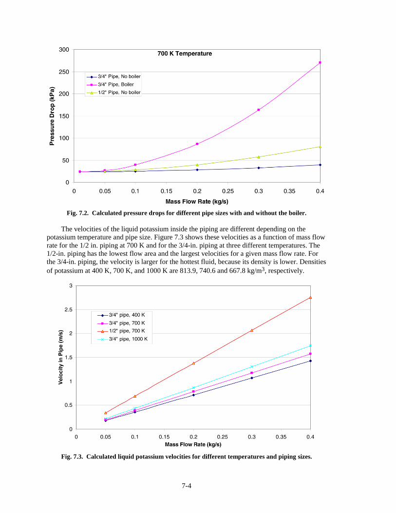
7-4
Fig. 7.2. Calculated pressure drops for different pipe sizes with and without the boiler.
The velocities of the liquid potassium inside the piping are different depending on the
potassium temperature and pipe size. Figure 7.3 shows these velocities as a function of mass flow rate for the 1/2 in. piping at 700 K and for the 3/4-in. piping at three different temperatures. The 1/2-in. piping has the lowest flow area and the largest velocities for a given mass flow rate. For the 3/4-in. piping, the velocity is larger for the hottest fluid, because its density is lower. Densities of potassium at 400 K, 700 K, and 1000 K are 813.9, 740.6 and 667.8 kg/m3, respectively.
Fig. 7.3. Calculated liquid potassium velocities for different temperatures and piping sizes.
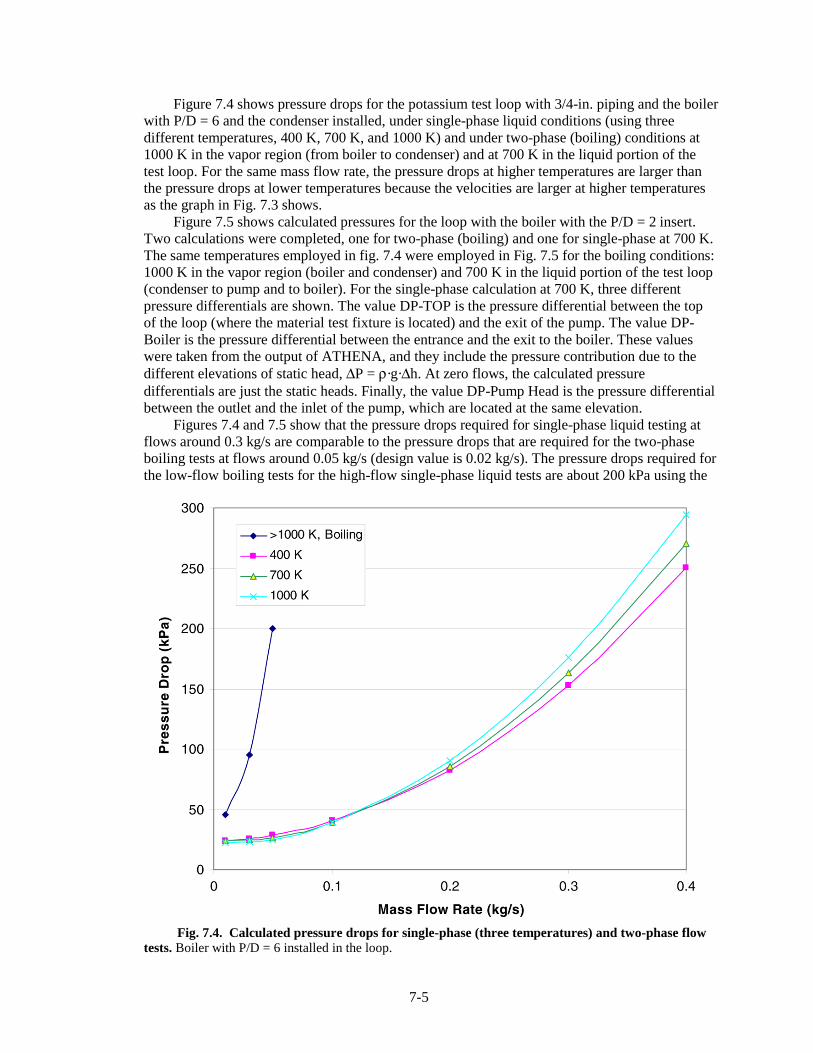
7-5
Figure 7.4 shows pressure drops for the potassium test loop with 3/4-in. piping and the boiler with P/D = 6 and the condenser installed, under single-phase liquid conditions (using three different temperatures, 400 K, 700 K, and 1000 K) and under two-phase (boiling) conditions at 1000 K in the vapor region (from boiler to condenser) and at 700 K in the liquid portion of the test loop. For the same mass flow rate, the pressure drops at higher temperatures are larger than the pressure drops at lower temperatures because the velocities are larger at higher temperatures as the graph in Fig. 7.3 shows.
Figure 7.5 shows calculated pressures for the loop with the boiler with the P/D = 2 insert. Two calculations were completed, one for two-phase (boiling) and one for single-phase at 700 K. The same temperatures employed in fig. 7.4 were employed in Fig. 7.5 for the boiling conditions: 1000 K in the vapor region (boiler and condenser) and 700 K in the liquid portion of the test loop (condenser to pump and to boiler). For the single-phase calculation at 700 K, three different pressure differentials are shown. The value DP-TOP is the pressure differential between the top of the loop (where the material test fixture is located) and the exit of the pump. The value DP-Boiler is the pressure differential between the entrance and the exit to the boiler. These values were taken from the output of ATHENA, and they include the pressure contribution due to the different elevations of static head, ΔP = ρ·g·Δh. At zero flows, the calculated pressure differentials are just the static heads. Finally, the value DP-Pump Head is the pressure differential between the outlet and the inlet of the pump, which are located at the same elevation.
Figures 7.4 and 7.5 show that the pressure drops required for single-phase liquid testing at flows around 0.3 kg/s are comparable to the pressure drops that are required for the two-phase boiling tests at flows around 0.05 kg/s (design value is 0.02 kg/s). The pressure drops required for the low-flow boiling tests for the high-flow single-phase liquid tests are about 200 kPa using the
Fig. 7.4. Calculated pressure drops for single-phase (three temperatures) and two-phase flow
tests. Boiler with P/D = 6 installed in the loop.

7-6
0
50
100
150
200
250
300
0 0.05 0.1 0.15 0.2 0.25 0.3 0.35 0.4
Mass flow rate (kg/s)
Pre
ssu
re d
rop
(kP
a)
DP-TOP, Boiling
DP-TOP
DP-Boiler
DP-Pump Head
Fig. 7.5. Calculated pressure drops for two-phase boiling at 1000 K and single-phase liquid at
700 K with the boiler (insert P/D = 2) and the condenser installed in the loop.
test loop configuration with the boiler and condenser installed. The calculated pressure drop at 0.35 kg/s (single-phase) is about 250 kPa. For a pump suction pressure of 150 kPa, the pump needs to supply a pressure equal to
P = 150 + 250 = 400 kPa .
Thus, a value around 400 kPa (59 psia) is the minimum pressure head that the pump has to supply for a maximum flow rate of 0.4 kg/s and at a maximum temperature of 700 K. If needed, the temperature of the potassium entering the pump can be reduced below 700 K by using the condenser as a cooler. The boiler can then be used to heat the potassium to the desired temperature (700 K for the single-phase tests and ~1000 K for the boiling tests).
Pressure drops through the test fixture were not considered in these calculations. This pressure drop needs to be added to the calculated values to determine the total pressure drop that needs to be supplied by the pump. For a pressure drop of 1400 kPa through the materials test fixture (as indicated in Sect. 3 of this report), the total pressure head that needs to be supplied by the pump would be
P = 400 + 1400 = 1800 kPa (262 psia) .
If the boiler is not installed in the test loop during the single-phase tests, the pressure to be supplied by the pump can be reduced by ~150 kPa at a flow of 0.3 kg/s for a reduction of 11%. This reduction is not significant based on the large total pressure requirement. Thus, with this large pressure drop through the test article, the pressure drop through the boiler is a burden that can be tolerated. Detailed models of pressure drops through the test fixture are not available at this time. A model of the loop with detailed models of the different test fixture contents and their

7-7
associated pressure drops should be prepared when the models are available and should be used for final calculations of pressure drops in the test loop.
In conclusion, using the proposed test loop configuration shown in Fig. 7.1 with the boiler and condenser installed for both single-phase liquid and two-phase boiling tests is acceptable. For this configuration, the resulting pressure drops are comparable for both types of tests, despite the large differences in flows that are required (when pressure drops through the test fixture are not considered). This configuration has the advantage that it does not require piping modifications to switch from the single-phase to two-phase flow tests.
Based on the ATHENA pressure drop calculations, the pump maximum design requirements follow:
• without the test article, maximum pressure head 400 kPa at a flow of 0.3 kg/s; and • with the test article, maximum pressure head 1800 kPa at a flow of 0.3 kg/s (design flow is
0.2 kg/s). 7.2 GETTER CONSIDERATIONS
Controlling oxygen levels in the potassium test loop is an important consideration for assuring reliable operations and meaningful testing results. Depending on the concentration, oxygen can cause corrosion of loop construction materials including certain types of stainless steel and form various oxides including potassium oxide (K2O), potassium peroxide (K2O2), and potassium superoxide (KO2). If the contamination level is significant, these oxides can result in plugging of potassium flow passages at locations where insoluble sediments collect or cause scoring, erosion, or other types of physical damage to exposed test loop components. To reduce and possibly avoid these types of problems, the following three actions are recommended:4–15
1. minimize test loop contamination by procuring vendor-supplied potassium that is as pure as possible,
2. minimize the introduction of related impurities from fabrication and construction activities, and
3. implement in-loop cleanup methods to achieve and maintain the required level of potassium purity.
The first step involves specifying and acquiring “high purity grade” (with <50 ppm oxygen)
rather than “commercial grade” (with up to 800 ppm oxygen) potassium. Although desirable, the timely availability of the high purity grade is not assured because there are currently only a limited number of potential potassium suppliers. As a second step, special care must be taken to minimize the introduction of impurities in the test loop by removing construction residue and other potential contaminants from the test loop piping system and its components. To further assist in accomplishing this objective, stringent precharge flushing and filtration (fine mesh, near-melting point) procedures need to be employed to minimize the quantity of oxygen initially present in the test loop. Finally, as the potassium circulates through the test loop, in-loop hot trapping should be performed to further reduce and then maintain the oxygen concentration at the required level for the test conditions.
After consulting various references, the hot trapping methods suggested by Peterson and Mausteller4,7 were chosen. The preferred strategy involves chemically converting oxygen-related soluble impurities circulating in the potassium test loop into captive insoluble compounds. For the potassium test loop, this conversion process can be accomplished using an appropriate quantity of zirconium to function as gettering material.
To maximize the surface area for a given mass of zirconium and thereby facilitate the desired chemical reactions, turnings, powder, and foil geometries were considered. Although

7-8
turnings and powder have more surface area than foil, they are also harder to handle, install, and confine. For this reason, sheets of zirconium foil were selected as the preferred geometry for the gettering material. In this design, zirconium foil is placed inside the sump tank and inside a heated hot-trapping vessel that is installed in a dedicated bypass line around the pump as shown in Fig. 6.2. These test loop design features are intended to promote the formation and attachment of insoluble zirconium oxide to the solid surfaces of the zirconium foil.
The primary purpose for installing zirconium in the sump tank is to further purify the vendor-supplied potassium prior to charging the test loop. To promote efficient installation and removal of the zirconium foil, special getter assemblies are designed and fabricated based on the configuration shown in Fig. 6.4. In this design concept, circular sheets of zirconium foil are separated by spacers and then bolted together to create a one-piece assembly that fits through the 6-in. weld neck flange welded to the top of the sump tank shell. This parallel array of zirconium foil minimizes assembly volume while permitting effective exposure to potassium. Published supplier information indicates that zirconium foil is available in thicknesses ranging from 0.001 to 0.009 in. The specified foil thickness of 0.005 in. represents a compromise between mechanical strength (thicker) and material cost (thinner). However, previous experience with zirconium suggests that it becomes very brittle when exposed to sodium, and similar behavior is possible upon exposure to potassium. For this reason, the final getter assembly specification may include thicker sheets of zirconium foil.
In this design, a similar type of getter assembly is installed inside the hot trap as it is being fabricated. Because the hot trap design does not include bolted closures, removal and replacement of the getter assembly is not possible. To identify the quantity of zirconium that should be placed inside the hot trap during its fabrication, an assessment was performed using two methods reported in various references.
In one method, Mausteller et al.4 suggest a rule-of-thumb range relating getter material surface area to liquid-metal volume. This information source recommends using 10 to 50 ft2 of getter material per cubic foot of liquid metal. The assumption of a 100-lb charge of potassium corresponds to 1.93 ft3 of potassium at its melting point. Based on this rule-of-thumb, the getter assembly should contain between 19.3 and 96.7 ft2 of zirconium. If 0.005-in. thick zirconium foil is used, the required zirconium volume range is 0.00806 to 0.04030 ft3. The weight of zirconium foil associated with this volume is 3.27 to 16.4 lb.
The second method suggests that the getter quantity be estimated by (a) determining the amount of oxygen to be removed, (b) calculating the theoretical getter capacity for oxygen, and (c) assuming that the actual getter capacity for oxygen is 10 to 20% of theoretical. Using this method yields an upper and a lower bound estimate for the quantity of zirconium needed.
• The lower limit of zirconium is calculated assuming the 100-lb potassium charge is “high purity grade” with an oxygen concentration of 50 ppm and that the zirconium has 20% of theoretical oxygen capacity. To reduce the oxygen concentration from 50 ppm to 5 ppm, 0.0045 lb of oxygen must be removed from the potassium charge. The theoretical gettering capacity (by formation of ZrO2) is 0.351 lb oxygen per pound zirconium (that is, 0.260 lb oxygen per pound zirconium oxide or about 260,000 ppm). The corresponding capacity at 20% of theoretical is 0.070 lb oxygen per pound zirconium (0.066 lbs oxygen per pound mixture or about 66,000 ppm). Based on this approach, the required minimum amount of zirconium is 0.0641 lb.
• The upper limit of zirconium is calculated assuming that the 100-lb potassium charge is “commercial grade” with an oxygen concentration of 800 ppm and that the zirconium has 10% of theoretical oxygen capacity. To reduce the oxygen concentration from 800 ppm to 5 ppm, 0.0795 lb of oxygen must be removed. The corresponding capacity at 10% of theoretical is 0.035 lb oxygen per pound zirconium [0.034 lb oxygen per pound mixture or about 34,000 ppm (note that postoperation analysis of zirconium gettering assembly contents

7-9
in a previous reference loop showed a maximum oxygen content of 3390 ppm, which was judged to indicate that the gettering material was not “used up”)]. The resulting maximum amount of zirconium using this estimation method is 2.27 lb.
Mausteller et al. have stated that oxygen levels in a potassium loop were reduced from
800 ppm to less than 50 ppm in 18 h at 1400°F using a 25:1 ratio by weight of alkali metal to zirconium turnings.4 On this basis, a 100-lb charge of potassium would require 4 lb of zirconium. Peterson7 has reported the use of 4 lb of zirconium in a bypass hot trap for a 50-kW potassium system (containing an unspecified amount of potassium).
In conclusion, the various assessment methods provide a wide range of estimates for the required amount of zirconium: from 0.064 lb to 16.4 lb for a 100-lb charge of potassium. The current recommendation is to procure potassium that is as pure as possible, to use 4 lb of zirconium for a 100-lb charge of potassium, and to provide enough zirconium (8 lb) for two complete 100-lb charges. If the zirconium is supplied as foil rectangles that are 0.005-in. thick, 3.9-in. wide, and 4.9-in. long, 352 such rectangles are required. 7.3 POTASSIUM-ARGON SEPARATION
During wear and bearing tests, potassium and argon are in contact with one another as they flow through the test fixture shown in Fig. 6.7. The intended direction of argon exit flow is generally upward toward an exhaust, while the intended direction of potassium flow is generally downward toward the cooler and pump inlet. When both fluids are flowing, two types of entrainment could occur—neither of which is desirable. One could take the form of “carryover,” regarded here as the entrainment of potassium liquid droplets into the argon gas stream exiting the test fixture. Because this stream is “flow-through” and, therefore, exhausted to the atmosphere, carryover would result in depletion of the recirculating potassium charge and would likely result in the need for liquid trapping or treatment of the effluent stream. The second type of possible entrainment could involve “carryunder,” regarded here as the entrainment of argon gas bubbles into the liquid potassium stream that exits the test fixture. In this situation, the argon bubbles would be incorporated into the recirculating potassium stream, possibly disrupting pump operation, flow measurement, heat transfer, and purity maintenance. To estimate the conditions under which undesirable “carryover” and “carryunder” might occur, existing analytical predictions and experimental correlations were employed to create relevant parametric models.
For the carryover case, it is assumed that, in order to be entrained, a liquid potassium droplet must be subjected to an upward drag force (imparted by argon gas flow) at least equal to the downward gravitational force on that same droplet. The simplest prediction for this case appears to be that by Stokes,16 which assumes that the droplet acts as a solid potassium sphere suspended in an argon flow that is laminar in character with no separation. The analytical results are most frequently expressed as an inverse linear relationship between the drag coefficient and the free-stream Reynolds number as shown in Fig. 7.6. For a 1-mm-diam potassium droplet in argon gas at 700 K and 200 kPa, the force balance gives a drag coefficient of 0.0813 at a Reynolds number of 295 (confirming the laminar flow assumption) and a corresponding relative upward gas velocity of 9.32 m/s as shown in Fig. 7.7. In other words, the Stokes method estimates that, for these conditions, an argon upward free stream velocity greater than 9.32 m/s can result in carryover of 1-mm diameter and smaller droplets. Alternatively, if an area (overflow cup, separator, etc.) is provided that reduces such upward velocities to less than this value, no carryover of 1-mm or larger droplets would occur.

7-10
Fig. 7.6. Sphere drag coefficient (potassium/argon systems).

7-11
Fig. 7.7. Terminal velocity vs drop diameter (potassium sphere in argon). Of course, the real droplet is not solid, and internal liquid circulation can reduce the effective
drag coefficient for a given Reynolds number as noted by Rybczynski.16 This correction, in turn, increases the required velocity for entrainment to 9.91 m/s (with a corresponding Reynolds number of 314)—an increase of 6% over the Stokes value for the stated conditions (see Figs. 7.6 and 7.7).
Unfortunately, experimental evidence indicates that separation effects can substantially increase effective drag for spheres in situations with free-stream Reynolds numbers greater than 1. Because the Reynolds numbers calculated under the no-separation assumptions employed by Stokes and Rybczynski, substantially exceed this value, further correction is required to account for flow separation effects. Based on available experimental data, White’s16 prediction, illustrated in Figs. 7.6 and 7.7, gives a required velocity for entrainment of 2.27 m/s (corresponding Reynolds number of 72)—a decrease of 76% from the Stokes value. At this point, as a conservative measure, it is recommended that separators for liquid droplets be designed to provide upward gas velocities below those predicted by the White method for the smallest credible droplet size (below and to the right of the White prediction in Fig. 7.7).
For the carryunder case, it is assumed that, in order to be entrained, an argon bubble must be subjected to a downward drag force (imparted by liquid potassium flow) at least equal to the upward buoyancy force acting on that same bubble. In this case, the simplest prediction is probably that of Peebles and Garber,17 in which bubble rise velocity in a gravitational field is

7-12
related only to the respective fluid densities and the surface tension characteristic of the fluid interface. As shown in Fig. 7.8, for an argon bubble rising through liquid potassium, this model gives a bubble rise velocity of 0.217 m/s, with no dependence of this velocity on bubble size.
The analysis by Stokes, noted above, can also be applied with the assumption that the bubble acts as a solid argon sphere suspended in a potassium flow that is laminar in character with no separation. As before, the analytical results are expressed as the inverse linear relationship between the drag coefficient and the free-stream Reynolds number shown in Fig. 7.6. For a 1-mm-diam argon bubble in liquid potassium at 700 K and 200 kPa, this force balance gives a drag coefficient of 0.00314 at a Reynolds number of 7650 (again confirming the laminar flow assumption) and a corresponding relative downward potassium liquid velocity of 2.04 m/s as shown in Fig. 7.8. In other words, the Stokes method estimates that, for these conditions, a potassium downward free stream velocity greater than 2.04 m/s can result in carryunder of a 1-mm-diam bubble. Alternatively, if an area (overflow cup, separator, etc.) is provided that reduces such downward velocities to less than this value, no carryunder of this diameter or larger bubbles would occur.
As with the droplet examined above, the real bubble is not solid, and internal gas circulation can reduce the effective drag coefficient for a given Reynolds number as noted by Rybczynski. This correction, in turn, increases the required velocity for entrainment to 2.81 m/s (with a corresponding Reynolds number of 10500) for the stated conditions (see Figs. 7.6 and 7.8)—an increase of 38% over the Stokes value.
Fig. 7.8. Terminal velocity vs bubble diameter (argon sphere in potassium).

7-13
Once again, separation effects can substantially increase effective drag for spheres in situations with free-stream Reynolds numbers greater than 1. Because the Reynolds numbers calculated above under the no-separation assumptions employed by Stokes and Rybczynski again substantially exceed this value, similar correction is required to account for flow separation effects. White’s prediction, illustrated in Figs. 7.6 and 7.8, gives a required velocity for entrainment of 0.136 m/s (corresponding Reynolds number of 512)—a decrease of 93% from the Stokes value. At this point, as a conservative measure, it is recommended that separators for gas bubbles be designed to provide downward potassium velocities below those predicted by the White method for the smallest credible bubble size (below and to the right of the White prediction in Fig. 7.8). 7.4 TEMPERATURE OSCILLATIONS IN LIQUID-METAL BOILERS
Temperature oscillations in liquid-metal boiler walls can induce material fatigue and boiler failure. Potential consequences of this phenomenon on useful service life were investigated to characterize the effects of the temperature oscillations in the walls of the space power conversion system boiler that uses Nb-1% Zr as a structural material. Although previous research for breeder reactor applications focused on this issue, additional experimental tests are recommended to resolve this potential problem with high confidence. The basis for this recommendation is established in the following discussion.
7.4.1 Introduction
The Rankine cycle employs potassium vapor generated in a boiler that is heated by lithium. This cycle has liquid lithium on the primary side of the boiler, and boiling potassium on the secondary side. During operation, temperature oscillations in the boiler wall may be a problem that can induce material fatigue and boiler failure. The purpose of this study is to characterize the effects of temperature oscillations in the walls of the space power conversion system boiler, which employs Nb-1% Zr as the structural material.
In general, a boiler consists of parallel tubes separating two different fluids: one circulating inside (tube side) and the other one circulating outside the tubes (shell side). These two sides are often referred to as the primary and the secondary side. The primary side can either be the inside or the outside of the tubes. In this context, heat is transferred from the primary side to the secondary side; therefore, the fluid in the primary side is hotter than the fluid in the secondary side. Boiling occurs in the secondary side. To improve the efficiency of the boiler, the flows in the primary and secondary sides are usually in opposing directions (countercurrent), but boilers with co-current flows are also common. In the case of water boilers, liquid water is converted into steam in the secondary side of the boiler. In the Rankine cycle space power conversion system boiler, liquid potassium is converted to potassium vapor in the secondary side of the boiler.
Figure 7.9 shows a schematic of the boiler wall, using liquid lithium in the primary side (left) and boiling potassium in the secondary side (right). There is a point in the secondary side of the boiler where the heat transfer regime changes from nucleate boiling, hNB,(with a large heat transfer coefficient and good wetting at the boiler surface) to transition or film boiling, hV,(with a low heat transfer coefficient and a relatively dry surface). This point represents the departure from nucleate boiling (DNB). At this point the liquid is at saturation conditions and is converted into saturated vapor. The liquid and vapor temperatures are similar at this point, around the saturation temperature, but the surface temperature of the boiler in contact with the liquid and with the vapor are very different. There is a significant temperature increase from the boiling (wet) side of the boiler wall, TB, to the vapor side of the wall, TV. The temperature gradient is therefore very steep around the boiling front or DNB point. Beyond the DNB point, different heat

7-14
Fig. 7.9. DNB point for the lithium/potassium boiler with
temperature gradients on both sides of boiler wall. transfer regimes are possible: transition boiling, film boiling, dispersed droplets and single-phase vapor. For simplicity, Fig. 7.9 shows only one generic heat transfer mode in the vapor region, but different (more than one) heat transfer modes may exist. This temperature gradient depends on the different heat transfer regimes that may be present in the vapor region and could range from moderate to significant.
Figure 7.9 shows the relative values of the temperatures, with the temperature of the lithium, TLi, being the highest temperature (left of the figure) and the saturation temperature of the potassium, Tsat, being the lowest temperature (right of the figure). Temperature TB is located at the actual location of DNB where the metal surface is in contact with the potassium boiling front. Temperature TV applies to the entire wall surface in contact with potassium vapor, the region above the DNB point. An almost constant temperature, T1, applies to all the left side of the boiler wall. Actual values of these temperatures are given later in this section (also in Table 7.1).
The boiler surface under nucleate boiling conditions has a temperature (TB) slightly higher than the liquid potassium at saturation (Tsat) because the nucleate boiling heat transfer coefficient (hNB����������������������������������������������������� �������� !���"�� ���# �$� �����B – Tsat, the temperature difference between the surface and the fluid). By contrast, the portion of the boiler in contact with the vapor has a temperature, TV, much higher than saturation. The heat transfer coefficient in the vapor region (hV���������������%������������ �����V – Tsat is needed to transfer even a small amount of heat.

7-15
Table 7.1. Comparison of Space Reactor and CRBR boilers
Variable Li/K boiler CRBR, Na/H20 boiler
Primary pressure 5 kPa (1 psia) 687 kPa (100 psia) Secondary pressure 935 kPa (136 psia) 11.44 MPa (1665 psia) &P 930 kPa (135 psi) 10.75 MPa (1565 psi) T primary 1346 K 666 K–719 K T secondary 1306 K 594 K &Tmax 40 K 125 K Oscillation frequency Unknown 0.3–1 Hz Operation time 15 years 30 years Partial loads Limited Likely hL, primary 51,674 W/m2K 27,783–40,000 W/m2K hNB, secondary 96,534 W/m2K 300,000–340,200 W/m2K hV, secondary 14,764 W/m2K 5,000–5,670 W/m2K hNB/hV ratio 6.5 60 Fatigue curve for 1144 K 673 K Material Nb–1% Zr 2¼ Cr-1 Mo
At the other side of the boiler wall, the primary side of the boiler, the boiler surface
temperature (T1) and the heat transfer coefficient, hL (liquid forced convection) do not change significantly in value along the length of the boiler. Of course, as the fluid in the primary side releases heat to the secondary side, its temperature decreases with position, but very gradually. The fluid in the primary side is usually circulated at high velocities, resulting in large forced convection heat transfer coefficients (hL) and a wall surface temperature (T1) close to the fluid bulk temperature (TLi).
As mentioned before, the temperatures of the primary-side wall surface are higher than the temperatures of the secondary-side surface, so heat is transferred from the primary to the secondary sides. The temperature gradient across the boiler wall (T1 – TB) is very large at the DNB point where nucleate boiling occurs, because a large amount of heat is transferred and a large temperature gradient across the wall is needed (q = k•dT/dx). Temperature gradients across the wall thickness at other axial locations along the wall (above the DNB point with vapor on the secondary side, and below the DNB point, with liquid forced convection on both sides) are much smaller than the temperature gradient at the DNB point. As discussed previously, the secondary-side surface temperature (TB) is close to the saturated liquid temperature (Tsat); the primary-side temperature (T1) is close to the primary fluid temperature (TLi). Beyond the DNB point with transition or film boiling, the amount of heat transferred to the vapor is very small, and a low-temperature gradient across the wall (T1 – TV) results. Thus, the secondary-side surface temperature (TV) is close to the temperature of the primary side (T1), and TV is much higher than the saturation temperature. This temperature gradient is on the secondary-side surface of the boiler at the DNB point, between the high temperature of the vapor region (TV) and the low temperature of the nucleate boiling region (TB). Therefore, two different temperature gradients occur at the DNB point: one across the boiler wall, radially between the primary and the secondary sides at the boiling point, (T1 – TB) and the other one axially along the wall surface of the secondary side, between the vapor region and the boiling region of the boiling front, (TV – TB). The axial temperature gradient is not as large as the radial one, and depending on the different heat transfer regimes present before and after the DNB point, the axial temperature

7-16
gradient may occur over a significant length, thus reducing the value of the temperature gradient � �' (��
The DNB point is not stationary but oscillates with time, moving in position back and forth along the boiler. This is typical of boiling processes, which are not stationary. The temperature gradients across the boiler wall move (oscillate) to different points of the boiler as the DNB point moves. These temperature oscillations across the boiler wall may cause thermal strain cycle fatigue.
The DNB oscillations were investigated in great detail for the boilers of the Clinch River Breeder Reactor (CRBR) using both analytical methods and data obtained at experimental facilities. A review of this investigation for the CRBR follows, together with its applicability to a space reactor boiler made of the refractory metal alloy Nb-1% Zr using liquid lithium in the primary side and potassium as the boiling liquid in the secondary side. 7.4.2 Clinch River Breeder Reactor
The CRBR was a fast breeder reactor designed in the 1970s with a total power of 975 MW(t). The reactor was never built, but the design was fairly complete with extensive research performed in some areas. The DNB temperature cycling across the boiler walls was one of the problems investigated in detail. The final reactor design consisted of three primary loops and three boilers. Each boiler had two parallel evaporators and one superheater in series with the two evaporators. The DNB temperature oscillations were expected to occur in the evaporator section of the boilers, where the water is converted into steam.
The evaporators were designed with liquid sodium in the primary side and water in the secondary side. The sodium and the water were flowing countercurrently. The material of the boilers was 2 ¼ Cr-1 Mo carbon steel.
In the CRBR design, under normal operating conditions, the sodium temperature was expected to decrease from 440ºC (713 K) at the inlet to 300ºC (573 K) at the exit of the evaporators. In the design, the water temperature increased from 293ºC (566 K) at the inlet to 330ºC (603 K) at the exit. At the DNB point, the sodium temperature in the primary was ~440ºC, and the water saturation temperature in the secondary was ~330ºC, resulting in a temperature difference across the wall of 110ºC. Beyond the DNB point, the temperature of the boiler surface increased to values around 400ºC, and the temperature difference across the wall was only 40ºC. Thus, the temperature across the wall could oscillate between 40°C and 110°C. The temperature gradient along the wall is ~70ºC. At partial powers (60%) the temperature of the sodium in the primary side is higher than 440ºC which results in larger temperature differences across the wall. These temperature gradients oscillate (move) in position along the boiler, creating thermal stresses that could result in fatigue in the wall of the boiler. The frequency of these oscillations was measured in one of the experimental facilities and were on the order of 0.3 Hz. 7.4.3 Analytical Studies of Thermal Fatigue for the CRBR
Several analytical studies were completed for the CRBR to study this effect. The studies performed by Rockwell International19–21 considered several variables in the calculations including: one-dimensional (1-D) and two-dimensional (2-D) calculations, frequency of the oscillations (between 0.1 and 5 Hz), and the shape of the curve defining the heat transfer coefficient as it changes (over time or position) from nucleate to film boiling (or heat transfer to the vapor). Three shapes of the heat transfer coefficient were considered: sine, square, and trapezoidal. The following variables were kept constant in these calculations: temperature of the water (at 321ºC), temperature of the sodium (at 433ºC), and the heat transfer coefficients (at the

7-17
limits of the shape variation), with values of 27,783 W/m2 K (sodium side), 340,200 W/m2 K (water side with nucleate boiling) and 5,670 W/m2 K (water side to vapor).
Results of these studies indicated that the square wave is the most severe shape, followed by the trapezoidal, and then by the sine shape. The square wave assumes that the heat transfer coefficient changes suddenly from the high to the low value. The other wave shapes have a transition region between both heat transfer coefficients. The calculations with the square shape exceeded the fatigue curve for the 30-year lifetime of the boilers. The sine shape with a frequency of 1Hz marginally passed the fatigue curve. Figure 7.10 (taken from Refs. 19 and 20) shows these results together with the fatigue curve of the boiler material. Point D for the square wave is above the fatigue curve. Point A for the sine wave at 1 Hz is on the curve.
It was thought that the sine wave was the most likely shape for the change in the heat transfer coefficient, and for that shape the results were acceptable. Also, it was found that 1-D calculations were nonconservative, and 2-D calculations should be performed to obtain more realistic values.
Other calculations22 at Argonne National Laboratory (ANL) indicated no fatigue for a sodium inlet temperature of 393ºC, but potential fatigue for a sodium temperature of 446ºC. Higher sodium inlet temperatures were to occur in the CRBR at partial loads, with the value of 446ºC at a load of ~60%. Thus, operation at partial loads in the CRBR would have resulted in higher sodium temperatures that would yield higher temperature gradients that could have resulted in boiler fatigue. 7.4.4 Experimental Tests for Thermal Fatigue for the CRBR
Two experimental facilities were built to address the problem of DNB temperature oscillations: one at ANL, The Steam Generator Test Facility (SGTF), described in Refs. 23 and 24, and the other one at General Electric (GE), the DNB corrosion facility, described in Ref. 23.
Fig. 7.10. Design fatigue curve for the CRBR boiler material at 399ºC.

7-18
The SGTF23,24 was a single vertical tube, 1-cm inside diameter, full heated length (13.1 m) duplicating the conditions of the CRBR steam generators including the material, flows, and temperatures. Water flowed upward inside the tube and sodium flowed countercurrently downward outside the tube in a surrounding annulus.
Some results of the SGTF tests were presented in Ref. 25. A summary of these results follows. Large amplitude (>45ºC), low frequency (<0.3 Hz), together with small amplitude (~10ºC), high frequency (0.3–1 Hz) temperature oscillations were measured in the experiments. The large amplitude oscillations corresponded to the oscillations of the DNB front moving while the small amplitude oscillations corresponded to the boiling process itself. It was also found that the shape of the heat transfer coefficient was a sine curve and that for temperature differences across the wall (between the sodium and the water side) above 90ºC, the equivalent alternating stress is above 100 MPa, which is marginal for meeting the ASME code requirements for the 30-year tube lifetime. For smaller temperature gradients, material fatigue failure is not predicted. 7.4.5 Tests for Exfoliation of the Protective Oxide Layer for the CRBR
The thermal strain cycling caused by the DNB temperature oscillations may also aggravate corrosion problems on the steam side of steam generators by:
(a) exfoliation of the protective oxide layer, (b) attack of the tube by soluble corrodent species (like sodium hydroxide), and (c) reduction of fatigue resistance due to the corrodent species.
The GE DNB corrosion facility26 consisted of a single horizontal test tube with an active heat transfer length of 4.88 m, duplicating the conditions of the CRBR boilers. Water was circulated inside the tube and sodium outside in countercurrent flow.
The results of tests performed under worst-case conditions (64% power and worst chemistry) for more than 2820 h, revealed no evidence of localized attack or accelerated corrosion on the steam side of the boiler. The thickness of the oxide layer was not influenced by the tests. Thus, it was concluded that this problem was not likely to occur for the life of the boiler.
These data were obtained for the oxide layer of the water side of the boiler. Because the space reactor boiler is made of different material and uses potassium instead of water, these results are not applicable to the space boiler, and it is therefore a failure mode that does not require consideration. 7.4.6 Application to the Space Reactor Boiler
From the analytical and experimental studies of the CRBR, it could be concluded that under certain conditions, the integrity of the CRBR SG tubes could have been compromised. These conditions (partial load, high temperature differences between primary and secondary sides) could result in potential tube failures during the 30-year life. It was also concluded that under normal operating conditions at 100% power, fatigue problems related to temperature oscillations were not likely to occur in the boilers.
The most significant operational parameters of the space reactor boiler and of the CRBR boilers are shown in Table 7.1. The space reactor boiler would employ different materials and fluids and operate under different conditions than the CRBR SGs. Liquid lithium would be the fluid in the primary side and liquid/vapor potassium the fluid in the secondary side of the boiler. The heat transfer coefficients for the Li/K boiler are taken from Ref. 27. The temperatures and pressures of the Li/K boiler are taken from calculations completed with the codes ALKASYS-SRPS (Ref. 28) and ATHENA (Ref. 29). The values for the CRBR boiler are taken from Refs. 19 and 22.

7-19
This table shows that the temperature differences across the boiler wall, &�max, and the ratio of the heat transfer coefficients (nucleate-boiling to film-boiling) are smaller in the Li/K boiler than in the CRBR boiler. The temperature difference in the Li/K boiler is ~1/3 the temperature difference in the CRBR boiler. The ratio of heat transfer coefficients in the Li/K boiler is ~1/10 the ratio of the heat transfer coefficients in the CRBR boiler. The effect of these two factors should be smaller temperature oscillations in the Li/K boiler wall compared to the oscillations in the CRBR SGs because of smaller temperature differences between the primary and secondary sides of the boiler. In addition, the operation time of the space reactor boiler is 15 years (half the operation time of the CRBR), and operation at partial loads should be limited in the space reactor. Operation at partial loads is a very important factor in the temperature gradients. Frequent operation at partial or low loads in the CRBR would have yielded higher temperature gradients more frequently with a higher probability of boiler failure. Whether low-power operating conditions are needed in space reactor boilers is not known; therefore, the impact of low-power operation on temperatures has not yet been studied. The values of the Li/K boiler in Table 7.1 are all calculated at 100% power.
Fatigue curves for Nb-1% Zr, the refractory metal to be used in the space reactor boiler, are similar to the fatigue curve of the CRBR boiler material (2¼ Cr-1 Mo) taken from Refs. 19 and 20. Fatigue curves for Nb-1% Zr were found only for temperatures up to 1144 K and up to a maximum of 107 cycles,30 and they are shown in Fig. 7.11, taken from Ref. 30. It should be mentioned that the operating temperature of the Li/K boiler would be much higher (1350 K) than the operating temperature of the CRBR SGs (~670 K). The Nb-1% Zr fatigue curve at 1140 K (Fig. 7.11) is similar to the fatigue curve of the CRBR SGs material at 672 K (Fig. 7.9). At 106
cycles, both curves yield almost identical stresses, 20 ksi. Although the frequency of DNB temperature oscillations in the Li/K boiler is not known, it
appears that the magnitude of the temperature oscillations in this boiler should be significantly smaller than in the CRBR boiler, and the probability of tube fatigue appears to be less likely than in the CRBR boiler.
There are not enough data to resolve this problem with total confidence. Additional data are needed on the frequency and magnitude of the oscillations in space reactor boilers. It is necessary also to know the proposed operation of the boiler: if and how long the space boiler is operated at low power, and the temperatures that occur during low-power operation. Low powers in the CRBR would have resulted in larger temperature gradients with greater potential for fatigue problems, but this may not be the case for space reactor boilers.
Fig. 7.11. Fatigue assessment results.

7-20
The following tests are recommended:
• temperature controlled testing in the loop described in this report to evaluate both frequency and magnitude of temperature oscillations at the DNB front.
• experimental tests to investigate the frequency of DNB temperature oscillations in a Li/K system with Nb-1% Zr material using the actual geometry of the boiler (assuming Nb-1% Zr is used in the actual boiler design).
• experimental measurements of the DNB temperature differences across the wall of the boiler. The values of Table 7.1 for these temperature differences are from analytical calculations, and experimental data would be very useful to check the analytical results.
• fatigue tests for Nb-1% Zr at temperatures up to 1350 K (lifetime tests). The current fatigue data are very limited and at temperatures lower than the temperatures of interest.
7.4.7 Summary
Studies of the DNB temperature oscillations across the wall of the CRBR boilers appeared to be a potential problem under low-power conditions, with material fatigue exceeding the limits for the 30-year lifetime of the boilers.
There are not sufficient experimental data to resolve this problem in the Li/K boiler with high confidence. Based on the available data, it appears that the probability of this problem occurring is very remote, less likely than in the CRBR boilers.
Experimental tests are recommended to resolve this problem. This experimental work should investigate the frequency and the amplitude of the temperature oscillations in Li/K boilers. Additional experimental work should investigate the fatigue in Nb-1% Zr at the temperatures of interest (1350 K). Also, the parameters, power, time, temperature, and duration of operation at low powers are needed to assess their effect on boiler lifetime. 7.5 PIPING ANALYSIS AND DESIGN CONSIDERATIONS
The multistep process of transforming the potassium test loop conceptual design into drawings and specifications suitable for field construction involves consideration of many structural and material issues. This process often involves a number of design, analysis, and redesign iterations to achieve a functional arrangement of components that complies with applicable piping codes and materials standards. Some of the more important topics that need to be considered include
• applicable code rules and acceptance criteria for high-temperature type 316 stainless steel piping systems;
• piping flexibility analysis to establish acceptable piping configurations and support locations for test loop components and piping;
• test loop component and insulation weights; • piping stresses and stress ranges resulting from internal pressure, thermal expansion,
attachments, and anchorages; and • fatigue and high-temperature creep phenomenon.
An overview of general piping analysis and design considerations, presented in Appendix B,
serves as a guide for establishing a final design for the potassium test loop.
7-21
7.6 REFERENCES
1. RELAP5 Code Development Team, RELAP5/Mod 3.2 Code Manual, Report NUREG/CR-5535 (INEL-95/0174), 1994.
2. G. L. Yoder, et al., Technology Development Program for an Advanced Potassium Rankine Power Conversion System Compatible with Several Space Reactor Designs—Final Phase I Report, ORNL/TM-2004/214, September 2004.
3. J. J. Carbajo and G. L. Yoder, “Modeling Liquid Metal Boiling with the ATHENA Code,” Space Nuclear Conference 2005, Paper 1068, San Diego, California, June 2005.
4. J. W. Mausteller, F. Tepp, and S. J. Rodgers, Alkali Metal Handling and Systems Operating Techniques, Gordon and Breach, Science Publishers Inc., 1967.
5. R. D. Brooks, Ed., Alkali Metals Boiling and Condensing Investigations, Vol. I—Experimental Program, NASA CR-54050, Contract NAS 5-681, SPPS, MSD, General Electric Company, June 1, 1964.
6. R. W. Ohse, Ed., Handbook of Thermodynamic and Transport Properties of Alkali Metals, Blackwell Scientific Publications, 1985.
7. J. R. Peterson, High-Performance “Once-Through” Boiling of Potassium in Single Tubes at Saturation Temperatures of 1500° to 1750°F, NASA CR-842, General Electric Company, Missile and Space Division, Cincinnati, Ohio, 1967.
8. J. Longo, “Alkali Metal Boiling and Condensing Investigations,” Quarterly Progress Report No. 6, NASA CR 54037, Contract NAS 3-2528, SPPS, MSD, General Electric Company, April 20, 1964.
9. F. E. Tippets, “Alkali Metal Boiling and Condensing Investigations,” Quarterly Progress Report No. 7, NASA CR 54038, Contract NAS 3-2528, SPPS, MSD, General Electric Company, April 20, 1964.
10. F. E. Tippets, “Alkali Metal Boiling and Condensing Investigations,” Quarterly Progress Report No. 8, NASA CR 54138, Contract NAS 3-2528, SPPS, MSD, General Electric Company, October 20, 1964.
11. F. E. Tippets and G. L. Converse, “Alkali Metal Boiling and Condensing Investigations,” Quarterly Progress Report No. 9, NASA CR 54215, Contract NAS 3-2528, SPPS, MSD, General Electric Company, October 20, 1964.
12. F. E. Tippets and G. L. Converse, “Alkali Metal Boiling and Condensing Investigations,” Quarterly Progress Report No. 10, NASA CR 54308, Contract NAS 3-2528, SPPS, MSD, General Electric Company, April 20, 1964.
13. F. E. Tippets and G. L. Converse, “Alkali Metal Boiling and Condensing Investigations,” Quarterly Progress Report No. 11, NASA CR 54405, Contract NAS 3-2528, SPPS, MSD, General Electric Company, April 20, 1964.
14. F. E. Tippets and G. L. Converse, “Alkali Metal Boiling and Condensing Investigations,” Quarterly Progress Report No. 12, NASA CR 54739, Contract NAS 3-2528, SPPS, MSD, General Electric Company, April 20, 1964.
15. F. E. Tippets and D. R. Ferguson, “Alkali Metal Boiling and Condensing Investigations,” Quarterly Progress Report No. 13, NASA CR 54890, Contract NAS 3-2528, SPPS, MSD, General Electric Company, April 20, 1964.
16. F. M. White, Viscous Fluid Flow, McGraw-Hill, 1991. 17. L. S. Tong, Boiling Heat Transfer and Two-Phase Flow, John Wiley and Sons, 1967. 19. M. J. Gabler, “The Nature and Effect of DNB in the Evaporator Steam Tubes,”
Rockwell International, TI-036-610-023, April 1975. 20. R. H. England, “The Structural Analysis of DNB in the Evaporator Steam Tubes,”
Rockwell International, TI-036-510-014, May 1975. 21. A. VonArx, “AI Prototype LMFBR Steam Generator,” Rockwell International, TI-036-
610-024, June 1975.

7-22
22. T. Chiang, D. M. France and T. R. Bump, “Calculation of Tube Degradation Induced by Dryout Instability in Sodium-Heated steam Generators,” Nucl. Eng. and Design 41, 181–191 (1977).
23. J. C. Whipple and C. N. Spalaris, “Design of the Clinch River Breeder Reactor Plant Steam Generators,” Nuclear Technology 28, 305 (March 1976).
24. H. C. Stevens, D. M. France, “Development of a Thermal-Hydraulic Test Facility for Full-Scale LMFBR Steam Generator Tubes,” Trans. Am. Nucl. Soc. 22, 538 (1975).
25. D. M. France, R. D. Carlson, T. Chiang, and R. Priemer, “Characteristics of Transition Boiling in Sodium-Heated Steam Generator Tubes,” J. Heat Transfer 101, 270 (May 1979).
26. D. N. Rodgers et al., “Corrosion Testing under Departure from Nucleate Boiling Conditions Modeling the Clinch River Breeder reactor Plant Steam Generator,” ASME paper 77-JPGC-NE-8, ASME-IEEE Joint Power Generation Conference, Long Beach California, September 1977.
27. J. R. Peterson, R. N. Weltmann, and M. U. Gutstein, “Thermal Design Procedures for Space Rankine Cycle System Boilers,” Intersociety Energy Conversion Conference, Vol. 1, IEEE, pp. 313–328, 1968.
28. J. J. Carbajo and G. L. Yoder, “Optimization of Rankine Space Power Conversion Systems with the codes ALKASYS-SRPS and DAKOTA,” Space Nuclear Conference 2005, Paper 1067, San Diego, California, June 2005.
29. J. J. Carbajo and G. L. Yoder, “Modeling Liquid-Metal Boiling with the ATHENA Code,” Space Nuclear Conference 2005, Paper 1068, San Diego, California, June 2005.
30. NASA-AEC Liquid-Metals Corrosion Meeting, Lewis Research Center, Cleveland, Ohio, Vol. I, pp. 221–225, NASA SP-41 (October 1964).

8-1
8. SUMMARY AND CONCLUSIONS
This project was part of NASA’s Prometheus Nuclear Systems and Technology Program and was aimed at developing a potassium Rankine cycle for space power conversion. Because of priority changes within NASA, the project was cancelled, and closeout documentation was prepared at the end of September 2005. Phase II of the project was being executed at that time. Part of the Phase II effort was to design, build, and initiate testing of a forced convection potassium loop that focused on examining critical potassium Rankine cycle issues. The objective of this activity was to reestablish potassium loop testing capability that had not been present in the United States for approximately 30 years. The major focus of the testing and therefore the loop design was to perform rotating equipment seal and bearing tests and examine boiling potassium processes. At the termination of the project the design of this loop had been initiated, and most of the components designed to at least the conceptual level. This report documents that design as it stood at the end of the project, and the logic behind some of the decisions made during the design process. The facility design was clearly still a work in progress, but most design and operating issues had been identified, and many resolved. Additionally, approvals for installing and operating this facility at ORNL were either received or forthcoming. The primary purpose for preparing this report is to establish a well-defined starting point for the next effort aimed at developing this power conversion system.

8-2

A-1
Appendix A
HYDROGEN GENERATION ANALYSIS

A-2

A-3
Appendix A HYDROGEN GENERATION ANALYSIS
A.1 INTRODUCTION
The Liquid-Metal Test Facility (LMTF) is a 2-h fire rated enclosure that would be installed in Building 5800, Room D111, to house high-temperature potassium experiments. It would be designed so that there would be no water sources located in the enclosure, and the potassium would be enclosed in a piping system that uses an inert cover gas to prevent any infiltration of oxygen or water vapor. Although these engineered barriers would be designed to isolate the potassium from exposure to air and water, a pipe break, weld failure, fatigue crack, or other type of material or physical damage to the piping system could result in a potassium leak. A.2 ENGINEERING ANALYSIS
If a break in the piping occurs allowing potassium to escape, and this potassium does not catch fire and burn, then hydrogen could be generated as a result of the water vapor in the air reacting with the potassium. The analysis presented here provides a conservative upper bound for the amount of hydrogen that could possibly be produced under this scenario.
The only source of water in the enclosure is the moisture in the air. The analysis that follows uses this fact to evaluate the potential for hydrogen evolution within the enclosure.
Enclosure dimensions are approximately
• minimum floor area—520 ft2 • minimum height—22 ft • room volume = 520 × 22 = 11,440 ft3 = 324 m3
The total number of moles of gas present in the room is
N = PV/RT = (1)(3.24 × 10⁸)/(82.05)(298) = 13,251 mol .
All of the air to the enclosure would be supplied from Room D111. The conditioned air supply system for Building 5800 is designed to provide 50% relative humidity (RH) air (or lower) to Room D111. If the air that is supplied to Room D111 has 50% RH (H2O pressure at 25oC is therefore 0.222 psia = 0.0151 atm), then the number of moles of water vapor is
n(H2O) = (0.0151)(13,251) = 200.12 mol .
Assuming that all of the air in the enclosure along with the water vapor in the air comes in contact and reacts with the pool of potassium, up to 200.12 mol of water vapor could react.
The equation for the potassium-water reaction is
K + H2O → KOH + 1/2 H2 .
For every mole of H2O there would be 1/2 mole of H2 produced. If all of the water vapor in the enclosure reacts with the potassium, 1/2 × 200.12 mol = 100.06 mol of hydrogen is produced.
100.06 mol of H2 = 0.202 kg = 2.45 m3 .

A-4
If this amount of hydrogen completely mixes with the remainder of the room air as it comes in contact with the potassium, the maximum percentage of hydrogen in the enclosure is 2.45/324 = 0.76%. This value is approximately 19% of the flammability limit (4%) for hydrogen.
An electrically powered ventilation system would be provided for the enclosure. It would be capable of removing any hydrogen that may be generated inside the enclosure and safely discharging it up a stack located on the roof of Building 5800. Intake openings for the ventilation system would be located at the highest point of the enclosure ceiling and would not be blocked by fire dampers. This design ensures that hydrogen cannot accumulate locally within the room even if the ventilation fan is not operating. Any hydrogen that is generated would flow naturally through the intake openings and up the ventilation system stack.
During normal operation, the ventilation system would provide a continuous supply of fresh air from Room D111 to the enclosure. Under these conditions, hydrogen could be continuously generated if all of the water in this air comes in contact with the potassium. Using information provided above for 50% RH air, for each mole of air that enters the room, 0.0151 moles of water vapor would be present, and 0.0076 moles of hydrogen could be potentially produced. One mole of air at atmospheric pressure and 25o C has a volume of
V = (1)(82.05)(298)/(1) = 2.445 × 104 cm3 .
0.0076 moles of hydrogen has a volume of
Vh = (0.0076)(82.06 )(298)/(1) = 186 cm3 , or again the volumetric ratio of hydrogen to air is
186/2.445 × 104 = 0.76% . This value is 19% of the hydrogen flammability limit. A.3 CONCLUSIONS
This engineering analysis confirms that the hydrogen concentration inside the enclosure cannot exceed a volumetric ratio of 0.76%. For this reason, explosion-proof electrical equipment is not required inside the enclosure. Explosion-proof electrical equipment is only required when the volumetric ratio of hydrogen equals or exceeds 1%, which corresponds to 25% of the hydrogen lower flammability limit.

B-1
Appendix B
PIPING ANALYSIS AND DESIGN CONSIDERATIONS

B-2

B-3
Appendix B PIPING ANALYSIS AND DESIGN CONSIDERATIONS
Transforming the potassium test loop conceptual design shown in Fig. 6.2 into drawings and
specifications suitable for field construction involves consideration of many structural and material issues. An overview of general piping analysis and design considerations is provided to serve as a guide for establishing a final design for the potassium test loop. B.1 PROBLEM DESCRIPTION
An analytical model of the potassium test loop piping system was prepared based on the dimensions provided in Fig. 6.2. This model served as a starting point for the initial stress analysis that was performed to quantify pressure and thermal stresses in the various pipe segments and to define piping stress limits based on applicable code rules for high-temperature type 316L stainless steel piping systems and components. Objectives of the stress analysis were to
• establish an acceptable piping configuration and support locations for test loop components and piping segments,
• evaluate the influence of applicable loads and load combinations on piping stresses, • identify candidate anchorage and support locations for the individual piping segments, and • assess potential consequences of fatigue and high-temperature creep phenomenon on the
structural integrity of the piping system. These analytical results serve as a baseline for the design, analysis, and redesign iterations needed to develop the final configuration of the potassium test loop that complies with applicable piping and pressure vessel codes and materials standards. B.2 APPLICABLE CODES AND STANDARDS
The final configuration of the piping system and supports for the potassium test loop must conform to design, construction, fabrication, and inspection rules contained in the Code for Pressure Piping, ASME B31.3 (Ref. 1). Certain components of the piping system such as the sump tank must comply with ASME Boiler and Pressure Vessel Code requirements, specifically Section II, Part D (Ref. 2) and Section VIII, Division 1 and Division 2 (Refs. 3 and 4). B.3 ASSUMPTIONS
The following assumptions were used to establish the basis for the stress analysis.
1. The potassium test facility is located inside Building 5800. Effects of wind, seismic forces, displacement of supports, shock, and vibration loads were not considered in the analysis.
2. The piping material, size, and dimensions were taken from the conceptual potassium test loop configuration shown in Fig. 6.2.
3. The operating conditions are 247 psig at 890°F, 100 psig at 1340°F, and 0 psia at 1340°F as discussed in Sect. 3.1. Analysis of external pressure effects is based on 0 psia at 1340°F.
4. The piping analysis is based on an internal pressure of 200 psig with the piping system operating at 1340°F. This is a conservative assumption because the design pressure at 1340°F is 100 psig.
5. The maximum number of operating cycles is less than 7000. 6. The basic quality factor for longitudinal welded joints, Ej, is 0.85.

B-4
7. The manufacturer’s permitted under-thickness tolerance is 12.5% of the nominal pipe wall thickness.
8. The corrosion allowance is 0.00008 in. (Ref. 5). 9. The radius of bends is approximately 1.5 times the nominal pipe diameter. 10. The allowable external pressure limit was used (ASME Sect. II, Part D, Fig. HA-4 for D/t >
10 is limited to 800°F for SST 316L, an alternative calculation based on UG-28(c)(2) for D/t < 10 was used).
B.4 LOADS IDENTIFICATION
Based on rules in ASME B31.3, Para 301, piping systems shall be designed to withstand the effects of pressure, temperature, and applied loads. For this analysis, three types of piping loads were considered.
• Sustained loads including both internal and external pressure (Para 301.2.1); dead loads for example, weight of piping components, insulation, and other superimposed permanent loads supported by the piping (Para 301.6.2); and live loads, for example, the weight of medium transported in operation or testing (Para 301.6.1).
• Expansion and contraction loads including thrusts and moments due to resistance by restraints (supports and attachments) or anchors (Para 301.7.1) and temperature gradients resulting from large rapid temperature changes (Para 301.7.2).
• Occasional loads such as seismic, wind, seismic displacement of supports, shock, and vibration were not considered in this analysis.
B.5 STRESS CATEGORIES
The two stress categories that must be considered to comply with ASME B31.3 requirements follow:
1. Sustained (primary) stresses caused by loads that may lead to unacceptably large deformation and rupture. These loads include (a) sustained loads of pressure and weight; and (b) occasional (short-term sustained) loads of liquid and vapor hammer, fluid slugging, wind, and earthquake.
2. Displacement (secondary) stresses caused by loads that are repeated and lead to fatigue failure. These loads include (a) thermal expansion (startup–shutdown) loads and (b) building settlement and anchor movements.
Both primary and secondary stresses may produce fatigue damage. B.6 ACCEPTANCE CRITERIA B.6.1 Design Stress Values for 316L SST
Allowable design stress values for metallic materials in ASME B31.3 are given in Para 302.3.2(d)(1) through (6). The basic allowable stress values shall not exceed the following:
Para 302.3.2(d)(1): the lower of 1/3ST (minimum tensile strength at room temperature) and 1/3Su (tensile strength at design temperature), the following values are obtained from Ref. 2, Table U, (p. 452) and Ref. 6 for SST 316L (Ref. 2 is limited to a maximum temperature 1000°F):

B-5
Temperature (°F) –20 to 100 890 1,000 1,340 (Ref. 6) Tensile strength (psi) 70,000 58,820 55,400 37,800 1/3Su (psi) 23,333 19,606 18,466 12,600
Para 302.3.2(d)(3): for austenitic stainless steel the lower of 2/3SY (minimum yield strength at room temperature) and 0.9SY (tensile strength at design temperature), the following values are obtained from Ref. 2, Table Y-1, (p. 554) and Ref. 6 for SST 316L (Ref. 2 is limited to a maximum temperature 1000°F):
Temperature (°F) –20 to 100 890 1,000 1,340 (Ref. 6) Yield strength (psi) 25,000 13,860 13,200 15,200 2/3SY/0.9SY (psi) 16,666 12,474 11,880 13,680
For the creep regime (time dependent and temperature > 700 ~ 800°F), the allowable stress shall not exceed the lowest of the following:
Para 302.3.2(d)(4): 100% of the average stress for a creep rate of 0.01% per 1000 h; the following values are obtained from Ref. 7, Fig. 60, p. 32 for SST 316L:
Average stress for a creep rate 0.00001%/h at temperature 1340°F is approximately 2900 psi.
Para 302.3.2(d)(5): 67% of the average stress for rupture at the end of 100,000 h; the following values are obtained from Ref. 7, Fig. 59, p. 32 for SST 316L:
Average stress to produce rupture in 100,000 h at temperature 1340°F is approximately 5000 psi; 67% of the average rupture stress is approximately 0.67 × 5000 = 3350 psi.
Para 302.3.2(d)(6): 80% of the minimum stress for rupture at the end of 100,000 h the following values are obtained from Ref. 7, Fig. 58, p. 31 for SST 316L:
Minimum stress to produce rupture in 100,000 h at temperature 1340°F is approximately 5000 psi; 80% of the average rupture stress is approximately 0.80 × 5000 = 4000 psi. From above, the basic allowable stress values shall not exceed 2900 psi.
B.6.2 Allowable Stresses for 316L SST Pipe
For the design calculations, the following basic allowable stresses at a piping installation temperature of 70°F and operating temperatures of 890°F and 1340°F were used (ASME B31.3, Para 302.3):
Temperature (°F) 70 890 1,340 Tension [Para 302.3(a)] (S, psi) 16,700 11,380 2,700 (Table A-1)
The allowable stress in shear is 0.80S and in bearing is 1.60S [Para 302.3(b)]. The
compression allowable stress is the same as in tension, and consideration shall be given to structural stability [302.3(c)]. From the allowable stress values given in Sects. B6.1 and B6.2, the basic allowable stress shall not exceed 2700 psi.

B-6
B.6.3 Allowable Displacement Stress Range
The allowable displacement stress range, SA, is calculated as follows [Para 302.3.5(d)]:
SA = f (1.25Sc + 0.25Sh) = 1 × (1.25 × 16.7 + 0.25 × 11.3) × 1,000 = 23,700 psi (for T = 890°F) , = 1 × (1.25 × 16.7 + 0.25 × 2.7) × 1,000 = 21,550 psi (for T = 1,340°F) ,
where Sc = basic material allowable stress at minimum (cold) temperature, Sh = basic material allowable stress at maximum (hot) temperature, f = stress-range reduction factor (= 1 for 7000 cycles or less, Table 302.3.5). When Sh is greater than SL, the allowable stress range is calculated by Eq. (1b) as follows:
SA = f [1.25(Sc + Sh) – SL] . For nonrepeated stresses (e.g., anchor movement due to building settlement), the allowable stress range is 3.0Sc. B.6.4 Allowable Internal Pressure Stress (Circumferential Stress)
Stresses due to internal pressure are considered safe when the wall thickness of the piping component meets the requirements of Para 304 as explained in Sect. B.7 below. B.7 DESIGN CALCULATIONS FOR PIPING SYSTEMS
The piping system will be designed in accordance with rules provided in ASME B31.3 and constructed using welded type 316L stainless steel components manufactured through the vacuum remelt process. A maximum operating pressure of 200 psig and a maximum operating temperature of 1340°F will be used as design criteria for the piping system and its various components. The conceptual potassium test loop configuration in Fig. 6.2 shows all piping to be 3/4-in. NPS, type 316L stainless steel (schedule 40 is recommended). The following analyses are required for compliance with ASME B31.3, Para 304. B.7.1 Straight Pipe Under Internal Pressure (Circumferential Stress)
The minimum required wall thickness of a straight pipe section is determined from Eq. (2) and Eq. (3a), Para 304.1.1(a) and Para. 304.1.2(a) as follows:
tm = t + c t = PD/2 (SE + PY)
= 200 × 1.05/2(2700 × 0.85 + 200 × 0.7) = 0.04312 in.

B-7
where
P = internal design pressure (200 psig), D = outside diameter of pipe in tables of standards and specifications (1.05 in., Refs. 4,
8, and 9), S = allowable stress value (2700 psi, Ref. 1, Table A-1), E = quality factor [0.85, Ref. 1, Table A-1B for SST A312 electric fusion weld tube
double butt tube (conservative)], Y = coefficient [0.7 (t < D/6 = 0.175), Ref. 1, Table 304.1.1 for austenitic steels at
temperatures greater than1150°F], C = additional thickness for corrosion [0.00008 in. (Ref. 5)].
The 3/4-in. schedule 40 pipe has a wall thickness of 0.113 in. (Refs. 4, 8, and 9). Because the
mill tolerance is usually 12.5% (Ref. 10) and corrosion allowance is 0.00008 in. (Ref. 5), then the effective wall thickness, t, will be 0.098795 in. Inserting the effective wall thickness in Eq. (3a), the maximum allowable pressure will be
P = 2Set/(D – 2Yt) [Eq. (3a)] = 2 × 2700 × 0.85 × 0.098795/(1.05 – 2 × 0.7 × 0.098795) = 497.4 psi .
The ASME B31.3 Code margin, ratio of maximum allowable pressure to the design pressure, is
497.4/200 = 2.49 .
B.7.2 Longitudinal Stress
The sum of longitudinal stresses due to sustained loads such as pressure and weight shall not exceed the product ShW [Para 302.3.5(c)]:
SL < ShW SL < 2700 × 0.6455 SL < 1742 psi
SL = pressure stress + weight stress + other sustained stress = SLP + j Mweight+other sustained loads/Z SLP = Pd2/(D2 – d2) = P/[(D/d)2 – 1] = 200/[(1.05/0.85241)2 – 1] = 386.6 psi
where d is the inside diameter (= 1.05 – 2 × 0.098795 = 0.85241). The section modulus is given by
Z = � /32)[(D4 – d4)/D] ��� /32)[(1.054 – 0.852414)/1.05]
= 0.06429 in.3

B-8
B.7.3 External Pressure
To determine the wall thickness for straight pipe under external pressure, the procedure outlined in the ASME Code, Section VIII, Division 1, UG-28 through UG-30 (Ref. 3) is followed as required by Para 304.1.3.
The maximum allowable external working pressure, Pa, for D/t > 10, is given by (Ref. 3):
Pa = 4B/3(D/t) where
t = thickness of pipe, in., D = outside diameter of pipe, in., L = total length (assume 12 in.), in., (D/t) = outside diameter to thickness ratio, (L/D) = length to outside diameter ratio,
A = factor (= 0.0075 from Fig. G, at given L/D = 11.43 and D/t =10.63, Ref. 2, p. 706),
B = factor (from Fig. HA-4, at give factor A and metal temperature T, Ref. 2, p. 713).
Figure HA-4 is limited to a maximum metal temperature 800°F; however, the design
temperature is 1340°F. In this situation, a value of factor B cannot be obtained from Fig. HA-4, and an alternative formula may be used as follows:
Because D/t = 10.63, this can be approximated by D/t ~ 10, and the procedure given in UG-28(c)(2) step 3 for D/t values < 10 (Ref. 3) is used for D/t = 10.
Pa = [2S/(Do/t)] [1 – 1/(Do/t)] = (2 × 2700/10) (1 – 1/10) = 486 psi where
S = allowable stress value (2700 psi, Ref. 1, Table A-1).
The ASME B31.3 Code margin, ratio of maximum allowable pressure to the design
pressure, is approximately:
486/14.7 = 33 . B.7.4 Pressure Design for Pipe Bends
The minimum required wall thickness of a pipe bend is determined from Eqs. (3c) through (3e), Para 304.2.1 (Ref. 1) as follow: t = PD/[2(SEW/I) + PY)] [Eq. (3c)] = 200 × 1.05/[2 (2700 × 0.85 × 0.6455/1.25) + 200 × 0.7)] = 0.08366 in. (at the intrados)

B-9
= 200 × 1.05/[2 (2700 × 0.85 × 0.6455/0.875) + 200 × 0.7)] = 0.0596 in. (at the extrados)
I = [4 (R1/D) – 1]/[4(R1/D) – 2)] [at the intrados (inside bend radius), Eq. (3d)] = (4 × 1.5 – 1)/(4 × 1.5 – 2) = 1.25 (for bend radius/pipe diameter = 1.5)
I = [4 (R1/D) + 1]/[4 (R1/D) + 2)] [at the extrados (outside bend radius), Eq. (3e)] = (4 × 1.5 + 1)/(4 × 1.5 + 2) = 0.875 (for bend radius/pipe diameter = 1.5)
where P, D, S, E, and Y as defined above in Sect. B7.1, R1 = radius of bend assumed equal to 1.5 pipe diameters (Ref. 10),
W = weld joint strength reduction factor, per Para 302.3.5(e) W = 1.0 at temperature <950°F, and W = 0.5 at temperature = 1500°F and linearly interpolated for intermediate temperatures.
The wall thickness of the 3/4-in. standard commercial 90-degree long radius butt welding
elbow is 0.113 in. (Ref. 11, Table A2.21). Assuming the same mill tolerance and corrosion as in the straight pipe the effective wall thickness, t, will be 0.098795 in. Inserting the effective wall thickness in Eq. (3c), the maximum allowable pressure will be
P = 2SEtW/[(D – 2Yt) I] = 2 × 2700 × 0.85 × 0.098795 × 0.6455/[(1.05 – 2 × 0.7 × 0.098795) × 1.25] = 257 psi . The ASME B31.3 Code margin, ratio of maximum allowable pressure to the design pressure, is
257/200 = 1.28 .
B.7.5 Piping Flexibility Requirements
Sufficient flexibility of the piping system is required to prevent thermal expansion or contraction or movements of piping supports. The nominal thickness and outside diameter of pipe and fittings are used in flexibility calculations. The displacement stress range, SE, is determined from Eq. (17) Para 319.4.4 as follows:
SE = (Sb
2 + St2)0.5
Sb = [(iiMi)2 + (ioMo)2]0.5]/Z St = Mt/2Z where Sb = resultant bending stress, St = torsional stress, Mt = torsional moment, Z = section modulus of pipe, Mi = in-plane bending moment, Mo = out-plane bending moment, ii = in-plane stress intensification factor (= 0.9/h2/3 for bends, Table D300), io = out-plane stress intensification factor (= 0.75/h2/3 for bends, Table D300),

B-10
h = flexibility characteristic (= tR1/r22, r2 = mean radius, R1 = bend radius, Table D300),
k = flexibility factor (= 1.65/h for bends, Table D300).
The displacement stress range SE shall not exceed the allowable stress range SA. Analytical methods or commercial programs (e.g., AutoPIPE, Ref. 15) may be used to estimate the pipeline flexure stresses caused by expansion or movement of supports. Section B.9 contains the AutoPIPE analysis of the conceptual potassium test loop piping system. The maximum displacement stress, SE, predicted by AutoPipe is 20,514 psi as given in the result summary in the output file, and the allowable stress range, SA, is 21,550 psi (at temperature from ambient 70°F to maximum design temperature 1340°F, see Sect. B.6.3). The safety margin over allowable stress range is 21,550/20,514 = 1.05. B.7.6 Reactions
The reaction forces and moments on supports and connected equipment are determined as the algebraic difference between the value at maximum temperature and the value at the installation temperature [Para 319.3.1(b)]. The maximum reactions for simple systems, Rm, are determined from Eqs. (22) and (23) Para 319.5.1 as follows:
Rm = R (1 – 2C/3)(Em/Ea) Ra = the greater of CR or C1R C1 = 1 – ShEa/SEEm where Ea = reference modulus of elasticity at 70°F, Em = modulus of elasticity at maximum metal temperature, R = range of reaction forces or moments (derived from flexibility analysis) corresponding
to the full displacement stress range and based on Ea, Rm = estimated instantaneous maximum reaction force or moment at maximum temperature, Ra = estimated instantaneous reaction force or moment at installation temperature, C = cold spring factor (varying from zero for no cold spring to 1.0 for 100% cold
spring), C1 = estimated self-spring or relaxation factor; use zero if value of C1 is negative, SE = computed displacement stress range, Sh = basic allowable stress at maximum metal temperature.
The above reaction equations are not applicable for multianchor piping systems and for two-
anchor systems with intermediate restraints. Section B.9 contains the AutoPIPE analysis of the conceptual potassium test loop piping system. B.7.7 Pipe Support Design Conditions
The design of pipe supports as given in Para 321 is based on all concurrent loads transmitted into the supports. These loads are defined in Para 301 and include weight, pressure, and temperature. Vibration, wind, earthquake, and shock loads are not applicable for this analysis. The pipe supporting system is designed to prevent stresses exceeding those permitted by ASME B31.3, leakage at joints, and excessive loads on connected equipment. The AutoPIPE software is

B-11
used to model the potassium test loop configuration. Pipe support location and other analytical results are presented in Sect. B.9. B.8 FATIGUE ANALYSIS
Rules for fatigue due to pressure cycling, thermal cycling, and other loadings are provided in ASME B31.3 Para 301.10 and Appendix F, Para F301.10. Appendix F, Para F301.10 refers to thermal fatigue on surfaces exposed to two fluids of different temperatures at the mixing point; this case is not considered in the current analysis. However, per Para K304.8, the fatigue analysis shall be performed in accordance with ASME Code, Section VIII, Division 2 (Ref. 4) or Division 3. Using the displacement stress predicted by AutoPIPE, 20,514 psi, in Fig. 5-110.2.2 (design fatigue curve for series 3XX high-alloy steel at temperature not exceeding 800°F, Ref. 4, p. 323) gives number of cycles 3 × 10⁶ (for the alternating stress amplitude in Fig. 5-110.2.2, Sa, is one-half of the alternating stress range).
Para K304.8.3 (pressure stress evaluation for fatigue analysis) gives the following equation for the stress intensity at the inside surface of straight pipe due only to internal pressure (Eq. 37, p. 115):
S = PD2/{2 (T – c)[D – (T – c)]}
= 200 × 1.052/{2 (0.113 – 0.014205)[1.05 – (0.113 – 0.014205)]} = 1173 psi
where
S = stress intensity at the inside surface of the tube due only to internal pressure (psi), T = nominal thickness of pipe (0.113 in.), D = outside diameter of pipe (1.05 in.), P = design pressure (200 psi), C = corrosion and mechanical allowance (0.00008 + 0.014125 = 0.014205 in.).
The value of S, 1173 psi, is much less than three times the allowable stress in tension (3 × 13,500 psi for 316L at an average temperature of 700°F) given in Table K-1 of Ref. 1. In this case the inelastic analysis is not required per Para K304.8.3(c). Also the value of S, 1173 psi, is less than the allowable stress of 316L at 1340°F (2700 psi). B.9 PIPE SUPPORT DESIGN AND AUTOPIPE ANALYSIS
An acceptable support spacing for the predominant 3/4-in. schedule 40 pipe is determined to provide guidance for the support layout. Pipe properties from Ref. 12 (Table 1, p. 7–16) are outside diameter = 1.050 in. and nominal wall thickness = 0.113 in. The chosen pipe material is 316L stainless steel. The density of this material is 0.29 lb/in.3 (Ref. 13, pp. 46, 47). The distributed weight of pipe is
{ } lb/in.096.0.)]in113.0(2in.050.1[)in.050.1(4/lb/in.29.0 223 =−−π=pw
The content is liquid potassium. The density of the contents is 43 lb/ft3. The distributed weight of contents is

B-12
[ ] lb/in.013.0.)in113.0(2in.050.14//ftin.1728
lb/ft43 233
3
=−π=cw
Potential insulation is Thermo-12 Gold (Ref. 14). Density of insulation is 14.5 lb/ft3, and conductivity is 0.65 Btu-in./(h-ft2-°F) at an average temperature of 700°F. (Ref. 15). Distributed weight of the assumed thickness of 2.5 in. of insulation is
lb/in.234.02
.in050.1in.5.2
2
.in050.1
/ftin.1728
lb/ft5.1422
33
3
=⎥⎥⎦
⎤
⎢⎢⎣
⎡⎟⎠⎞⎜
⎝⎛−⎟
⎠⎞⎜
⎝⎛ +π=iw
[As a check on the computer program, note that (0.096 lb/in. + 0.013 lb/in. + 0.234 lb/in.)(12 in./ft) = 4.12 lb/ft.]
Specifications for the pipe allow a mill tolerance of 12.5% on wall thickness. Taking the maximum tolerance, the longitudinal stress in the ¾-in. pipe due to an internal pressure of 200 psi from equilibrium is
psi431)in.113.0()875.0(2
)in.113.0(875.02
in.050.1psi200
2=
⎥⎦⎤
⎢⎣⎡ −
==σt
rPp .
Conservatively assuming simple supports or a cantilever, the maximum moment due to
weight in the pipe with a horizontal span of L between supports is
222
0429.08
)lb/in.234.0lb/in.013.0lb/in.096.0(
8L
LLwM w =
++== .
The section modulus of the 3/4-in. pipe, considering mill tolerance, is
[ ]{ }3
44
in.0643.0
2
.in050.1
)in.113.0()875.0(2.in050.1)in.050.1(64 =
−−π
=S .
So peak bending stress in the ¾-in. pipe due to weight is
243
2
lb/in.667.0in.0643.0
lb/in.0429.0L
L
S
M ww ===σ .
In accordance with ASME B31.3 requirements, the allowable stresses are 3500 psi at
1300°F and 2500 psi at 1350°F. At the maximum design temperature, 1340°F, the allowable stress is
psi2700F1300F1350
psi3500psi2500)F1300F1340(psi3500 =
°−°−
°−°+ .

B-13
The maximum allowable span can be determined from the limit on stress due to internal pressure plus bending stress due to weight. That is 2700 psi = 431 psi + 0.667 lb/in.4 Lmax
2. So Lmax
2 = (2700 psi – 431 psi)/(0.667 lb/in.4) = 3404 in.2 and Lmax = 58.3 in. or 4 ft 10 in. Note that pressure is a minor component of the total stress and that the insulation weight dominates the distributed load.
Spans are also limited by deflection, but because the system may run for several weeks, for example, 1000 h, at temperature, check the maximum span to limit deformation due to creep. Three creep data points at 1350°F for 316L are available in Simmons and Echo (Ref. 7) (p. 134):
Stress (ksi)
Test duration (h)
Elongation (%)
15.0 277.4 56.0
10.0 1823.3 40.0
8.0 4873.9 24.0
These data were linearized by taking logs, and a least squares fit was found. The resulting equation tc
92108.4231058281.1 σ×=ε − produces strains of 1.56 in./in., 1.40 in./in., and 1.24 in./in., respectively for the stresses and times from the data. The approximation is acceptable.
Extrapolating down to the peak stress due to pressure and gravity yields in./in.0012.0)1000()2700(1058281.1 92108.423 =×=ε −
c This is greater than yield strain, so some creep deformation is expected.
At the allowable stresses due to restraint of thermal expansion, the pipe is expected to creep and cause permanent deformation if the pipe was hanging exposed between supports. However, the stiff insulation and protective cover on the outer surface will maintain the shape of the pipe especially if joints between upper and lower blocks of insulation are staggered and not allowed to line up except at bends.
To design a support configuration for the conceptual pipe configuration, a finite-element model was developed using the AutoPIPE pipe analysis program. This program is used to evaluate compliance with ASME B31.3 Code design rules. The program also selected spring rates and preload for spring hangers.
To minimize analysis for this conceptual design, bounding values of pressure and temperature were combined, so the system was evaluated for an internal pressure of 200 psi at the maximum temperature of 1340°F. Results of the analysis are summarized in Table B.1.
The sump tank, expansion tank, hot trap and separator were all modeled as pipe and all properties of standard pipe were available from internal AutoPIPE tables. All material was identified as 316L, which is conservative because, although the low carbon type of 316 is allowed to be used at 1340°F by ASME B31.3, the ASME Boiler and Pressure Vessel Code does not list properties for 316L above 800°F. This implies that the sump tank and the expansion tank, which must comply with the ASME Boiler and Pressure Vessel Code, would be constructed of a different material, such as 316H, which has higher allowable stresses. Fictitious rigid pipe elements were used to connect the sump tank supports and nozzles to the center line of the tank body. The AutoPIPE program calculates the distributed weight of the pipe from the tabulated nominal pipe dimensions. The distributed weight of the contents was calculated using a density of 43 lb/ft3. Pipe wall thickness tolerance or mill tolerance and a corrosion allowance of 0.00008 in. was used to calculate stress in the pipe elements.
Although exact piping insulation details are not finalized, a 2-1/2 in. thickness of rigid ceramic insulation was used in the analysis. All of the 3/4-in. pipe was identified as insulated

B-14
Table B.1. AutoPIPE results summary
------------------------------------------------------------------------------POTASSIUMLOOP 09/20/2005 POTASSIUM TEST LOOP DAC-EA-920102-A002, REV. 0 08:50 AM AutoPIPE+8.50 RESULT PAGE 73 ------------------------------------------------------------------------------ R E S U L T S U M M A R Y ---------------------------- Maximum displacements (in) --------------------------- Maximum X : -1.665 Point : G25 Load Comb.: GRT1 Maximum Y : 1.820 Point : G33 F Load Comb.: T1 Maximum Z : 0.557 Point : G11 Load Comb.: T1 Max. total: 2.286 Point : G33 N Load Comb.: T1 Maximum rotations (deg) ----------------------- Maximum X : 0.589 Point : G04 Load Comb.: T1 Maximum Y : -1.394 Point : G04 Load Comb.: GRT1 Maximum Z : 2.007 Point : G71 N Load Comb.: T1 Max. total: 2.014 Point : G71 N Load Comb.: T1 Maximum restraint forces (lb) ------------------------------ Maximum X : -62 Point : G88 Load Comb.: T1 Maximum Y : -505 Point : B00 Load Comb.: GRT1 Maximum Z : -51 Point : B00 Load Comb.: T1 Max. total: 511 Point : B00 Load Comb.: GRT1 Maximum restraint moments (ft-lb) ---------------------------------- Maximum X : 42 Point : M01 Load Comb.: GRT1 Maximum Y : -43 Point : B00 Load Comb.: GRT1 Maximum Z : -109 Point : B00 Load Comb.: GR Max. total: 109 Point : B00 Load Comb.: GR
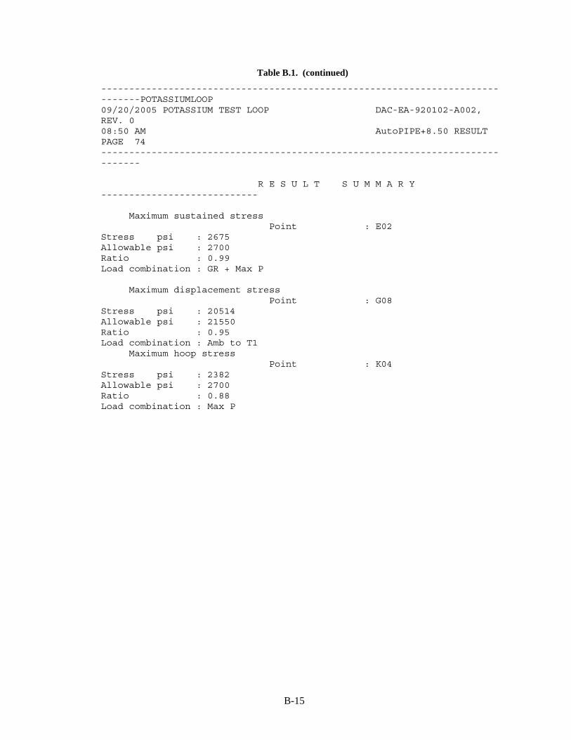
B-15
Table B.1. (continued)
------------------------------------------------------------------------------POTASSIUMLOOP 09/20/2005 POTASSIUM TEST LOOP DAC-EA-920102-A002, REV. 0 08:50 AM AutoPIPE+8.50 RESULT PAGE 74 ------------------------------------------------------------------------------ R E S U L T S U M M A R Y ---------------------------- Maximum sustained stress Point : E02 Stress psi : 2675 Allowable psi : 2700 Ratio : 0.99 Load combination : GR + Max P Maximum displacement stress Point : G08 Stress psi : 20514 Allowable psi : 21550 Ratio : 0.95 Load combination : Amb to T1 Maximum hoop stress Point : K04 Stress psi : 2382 Allowable psi : 2700 Ratio : 0.88 Load combination : Max P

B-16
Table B.1. (continued)
------------------------------------------------------------------------------POTASSIUMLOOP 09/20/2005 POTASSIUM TEST LOOP DAC-EA-920102-A002, REV. 0 08:50 AM AutoPIPE+8.50 RESULT PAGE 75 ------------------------------------------------------------------------------ R E S U L T S U M M A R Y ---------------------------- Maximum sustained stress ratio Point : E02 Stress psi : 2675 Allowable psi : 2700 Ratio : 0.99 Load combination : GR + Max P Maximum displacement stress ratio Point : G08 Stress psi : 20514 Allowable psi : 21550 Ratio : 0.95 Load combination : Amb to T1 Maximum hoop stress ratio Point : K04 Stress psi : 2382 Allowable psi : 2700 Ratio : 0.88 Load combination : Max P * * * The system satisfies ASME B31.3 code requirements * * * * * * for the selected options * * * except for the coils in the condenser and the cooler. The insulation thickness and a density of 14.5 lb/ft3 were supplied so the distributed weight of insulation could be calculated.
The finite-element model based on the conceptual configuration is shown in Fig. B.1. Support locations were chosen and the system responses to pressure, gravity, and restraint of thermal expansion loads, combined according to ASME B31.3 rules, were calculated by AutoPIPE. The model includes anchors at the following locations:
• supports for the sump tank (one of the sump tank supports is allowed to slip in one direction to allow free thermal expansion along the length of the tank),
• at the intake and outlet for the pump, and • at the inlet and outlet of the test fixture.
All of the other supports for the pipe segments were defined in the program as spring hangers. Spring properties were not defined, so the program could calculate optimum values.
The number and location of the spring hangers were initially chosen to limit distance between supports on horizontal runs to 4 ft 10 in. or less. The vertical runs of pipe were supported at ground level under the boiler and just above and below the condenser. Pipe stresses, calculated

B-17
Fig. B.1. AutoPIPE model of conceptual potassium test loop.
according to ASME B31.3 rules, based on the trial support configuration were compared with code allowable values. The supports were varied until the configuration shown in Fig. B.1 was obtained. The pipe stresses for this configuration all meet the code.
In addition to the supports on the vertical legs of the system below the boiler and on either side of the condenser, supports were placed near the hot trap and the expansion tank. The loop of pipe in the cooler was supported above and below. After these positions, a support was added every 4 to 5 ft along the horizontal runs. All of the supports were input as spring hangers with spring constants to be determined by AutoPIPE. The program selected rigid clevis hangers for all positions. All supports must allow thermal growth up to 2.286 in. which requires relatively long rod hangers above the pipe for clevis supports and roller supports from below.

B-18
B.10 CONCLUSIONS AND RECOMMENDATIONS
The following conclusions and recommendations are based on results of the stress analysis that was performed.
• Use of Type 316L stainless steel as a construction material for the potassium test loop may be feasible, but the ASME Boiler and Pressure Vessel Code does not permit its use at the required operating temperatures and pressures. Type 316H stainless steel is an acceptable construction material for these operating conditions that should be considered as an alternative material during the final design process.
• The configuration of the piping system shown in Fig. 6.2 does not need to be changed to comply with ASME Code requirements for the single temperature and pressure conditions considered in the initial stress analysis. Modifications to the configuration may be required during final design when stress for other operating conditions is considered.
• Fatigue in not a significant design consideration because the potassium test loop would not experience more than 7000 complete heat-up and cool-down cycles.
• The pipe support and anchorage arrangement described in Sect. B.9 provides guidance for locating and selection of pipe hangars for the potassium test loop.
• Use of butt welding fittings and connections is acceptable. • In the final design for the potassium test loop, the actual thermal insulation properties (type,
density, thickness, etc.) may differ from those used in the initial stress analysis. This difference should be reflected in the final analysis because the weight of the thermal insulation could affect the locations of the anchors and the stiffness of the supports.
• The initial stress analysis was based on a maximum uniform temperature of 1340°F and a constant internal pressure of 200 psig. Piping temperatures and pressures used in the final analysis should be based on the temperature and pressure conditions for the actual modes of operation.
B.11 REFERENCES
1. ASME Code For Pressure Piping, B31, Process Piping, ASME B31.3-2004. 2. ASME Boiler and Pressure Vessel Code, Section II, Part D, 2004. 3. ASME Boiler and Pressure Vessel Code, Section VIII, Division 1, 2004. 4. ASME Boiler and Pressure Vessel Code, Section VIII, Division 2, 2004. 5. D. H. Jansen and E. E. Hoffman, Type 316 Stainless Steel, Inconel, and Haynes Alloy No.
25 Natural-Circulation Boiling Potassium Corrosion Test Loops, ORNL-3790, Oak Ridge National Laboratory, June 1965.
6. Francis J. Clauss, Engineer’s Guide To High-Temperature Materials, Addison-Wesley Publishing Co., 1969.
7. W. F. Simmons and J. A. Van Echo, Report on the Elevated-Temperature Properties of Stainless Steels, ASTM DS 5-S1, American Society of Testing and Materials, 1965.
8. Marmon/Keyston Corp., The Pipe and Tubing People, Butler, Pennsylvania. 9. T. Baumeister et al., Marks’ Standard Handbook for Mechanical Engineers, 8th Ed.,
McGraw-Hill, 1978. 10. BWXT Y12 Y/TIS-0079, ASME B31.3 Process Piping Design Training, D 50262169,
Q 50262167, by Ronald Haupt, May 2003. 11. M. L. Nayyar et al., Piping Handbook, 6th Ed., McGraw-Hill, Inc., 1967. 12. R. C. King and S. Crocker, Piping Handbook, 5th Ed., McGraw-Hill Book Company,
1967. 13. Properties of Some Metals and Alloys, 3rd Ed., The International Nickel Company,
1977.

B-19
14. Thermo-12 Gold Pipe & Block Insulation,” Guide IIG-400, Industrial Insulation Group, April 2004.
15. Bentley AutoPIPE, +8.50 Version 08.05.00.16, Bentley Systems, 2004.

B-20