testbed design and localization in mint-2: a miniaturized...
TRANSCRIPT

Testbed Design and Localization in MiNT-2: AMiniaturized Robotic Platform for Wireless Protocol
Development and EmulationChristopher Mitchell∗, Vikram Munishwar, Shailendra Singh, Xiaoshuang Wang,
Kartik Gopalan, Nael Abu-GhazalehComputer Science, Binghamton University (State University of New York)∗S*ProCom2, The Cooper Union for the Advancement of Science and Art
Contact: {kartik,nael}@cs.binghamton.edu
Abstract—The proliferation of wireless-enabled portable com-puting devices has spurred a growing need for efficient andpowerful networking protocols. The most significant challengein the development of robust wireless networking protocols isoften the need to prototype and test these protocols in a small-scale testbed before they can be widely deployed. Two contrastingprototyping and testing methods are currently used, requiringa choice between convenience and accuracy. The first involvessimulating a wireless network solely in software, but fails toaccurately account for real-world factors such as realistic radiopropagation models and their interaction with node mobility andobstacles. The second relies on setting up a large-scale physicaltestbed that, although accurate, represents a single design pointand tends to be expensive to reconfigure and manage. TheMiNT project at Stony Brook University was one of the firstto propose an accurate and inexpensive small-scale physicaltestbed built using commercially-available robots coupled witha version of NS2 built to work cooperatively on multiple nodes.MiNT combines the best features of the two popular performanceevaluation methods, achieving network accuracy comparable tothat of large-scale physical testbeds without abandoning theconvenience and flexibility of software simulation. In this paper,we describe our initial experiences in developing MiNT-2, thenext generation of MiNT. MiNT-2 represents a fresh redesignof MiNT that at once simplifies and improves the originaldesign, and extends it with a range of new features. The paperdescribes a number of these improvements including the new,simplified, node design, improved node localization approachusing RFIDs, position calibration and layout configuration. Wealso demonstrate the high accuracy of the new localizationapproach and outline planned testbed improvements.
I. INTRODUCTION
The widespread use of wireless communications devices hasled to extensive research into new powerful and robust wirelessnetworking protocols and applications. A major challenge cur-rently facing researchers and developers is testing a wide rangeof deployment scenarios and protocol execution modes inaccurate, real-world conditions. The two predominant optionsfor research and development in multi-hop wireless networksare software-only simulation and experimentation using large-scale testbeds. Network simulators [1]–[3] are particularlypopular due to the convenience of evaluating a variety ofnetworking configurations in a controlled and fully observableenvironment without setting up a physical testbed. However,
network simulator are also known to provide insufficientfidelity [?], [4], [5] in capturing radio propagation effects suchas non-uniform path loss, multi-radio interference, and multi-path fading. In fact, most published papers simply rely onthese tools without double-checking their validity, presumablydue to lack of alternatives.
Recognizing these limitations, an increasing number ofwireless researchers choose to validate their protocols byperforming tests on large-scale custom-built wireless networktestbeds [6]–[8]. Although empirical results collected fromthese testbeds are certainly more credible, initial experienceswith them reveal several fundamental limitations. These in-clude a lack of sufficient flexibility in reconfiguring theinitial topology, mobility patterns, or radio settings, significantmanual maintenance effort required to program and rechargenodes, lack of autonomous 24x7 operation, and most im-portantly, large physical space requirements due to relativelylong-range radio coverage. These issues make testbeds limitedin terms of their ability to provide a range of experimentalscenarios for evaluation, and extremely expensive from thestandpoints of experiment setup and routine maintenance.
A. Wireless Emulation Testbeds
Wireless network emulation testbeds provide the high fi-delity of testbed experimentation combined with flexible net-work reconfigurability, at the same time significantly reducingthe physical space requirement for developing and testingwireless networking protocols. The MiNT [9], [10] testbed firstdeveloped at the Stony Brook University is one of the firstemulation testbeds developed. Two key architectural decisionsin the MiNT testbed were (1) the use of mobile robots totransport wireless network nodes, and (2) the use of radiosignal attenuators to shrink the physical space requirementsof a multi-hop wireless testbed. Each MiNT node is builtfrom a mobile robot and an embedded computer equippedwith multiple IEEE 802.11a/b/g WLAN interfaces. The robotsused in the MiNT testbed are inexpensive Roomba [11] robotsfrom the iRobot Corporation, which can be programmaticallyinterfaced using a well-defined serial API.

MiNT significantly shrinks the physical space requirementof a multi-hop wireless network testbed through controlledattenuation of the radio signals being transmitted and received.This drastically decreases the setup, fine-tuning, and manage-ment efforts required to tailor a testbed to the needs of aprotocol study. MiNT also permits the user to configure anarbitrary initial network topology and to set up a node mobilitypattern to be executed during an experiment. MiNT automatesthe support for such flexibility through physical-level radiosignal measurements and computer vision-based robot posi-tioning and navigation techniques. A self-charging mechanismallows each Roomba robot to detect a nearly-depleted batteryand find a docking station to recharge. These features madeMiNT the first known wireless robot-based testbed that cansustain 24x7 operation without human intervention.
II. MINT2: A FRESH RE-DESIGN
Our group at Binghamton University has recently beendeveloping MiNT-2 – the second generation of an improvedminiaturized robotic platform for wireless protocol develop-ment and testing. The goal of the MiNT-2 project is two-fold. First is to reproduce the MiNT testbed’s functionalityindependently to carry out wireless networking research withinour group. Second is to improve the original testbed designand operation along the way through use of more effectivealgorithms and technologies. In this paper, we document ourimplementation experiences in improving several aspects ofthe original MiNT testbed, but in particular testbed design andnode localization technique. Nodes in MiNT-2 are designedfor low cost and maximal functionality using the latest gen-eration of iRobot Create robots. The Create offers a mobil-ity platform with well-documented x86-compatible librariesand a bidirectional serial protocol for movement control andfeedback such as sensor information, battery charge level,proximity/cliff sensor data etc. A low-power x86-based em-bedded controller board interfaces with the robot and an RFIDreader, provides the multiple wireless interfaces necessary forsimulating MIMO and other multi-channel protocols, and runsa distributed “hybrid” version of the NS2 software package.Compared to the original MiNT testbed that used camera-basedlocalization, our MiNT-2 prototype uses a simpler and moreeffective three-stage system of motor commands, distancesensor feedback, and RFID tags on the floor of the testbed thatprovide authoritative position information. Power managementis also improved by directly running each node’s on-boardelectronics from its robot’s battery, which is automaticallycharged by the auto-docking procedure triggered from a lowbattery condition detected via the robot’s API. Although costreduction was not our primary objective, we did extensivelyuse commodity hardware to reduce per-node testbed costs toaround $1000 which is significantly cheaper than the nodesin the original MiNT testbed. In the remainder of the paper,we first give an overview of the current and planned featuresof MiNT-2, continue with details of improved node design,and localization, and finally present a preliminary performanceevaluation of our current testbed.
III. OVERVIEW OF MiNT-2 FEATURES
We now provide an overview of the key features of theMiNT-2 testbed as well as ongoing developments. This willbe followed by a detailed description of two aspects of thesystem design we explore in this paper, namely: MiNT-2 nodedesign and node localization.
[Miniaturization] MiNT-2 significantly reduces the physi-cal space requirement of a multi-hop wireless network testbed,just as in the original MiNT testbed does, by attenuating theradio signals in a controlled fashion. This space reductiondrastically decreases the setup, fine-tuning, and managementefforts required to tailor a testbed to the needs of a protocolstudy. A MiNT-2 node is an embedded computer mounted on aCreate robot [12] – a low-cost (less than $250) programmablerobot from iRobot. Create robot supports a basic set ofexternally controllable movements, is able to carry a largepayload (up to 30 pounds), and comes with an effective auto-recharging capability. Mounted on each Create is a Soekrisnet5501 embedded board, which is a low-power small-form-factor computer with a 433MHz processor and runs on powerfrom Create’s internal battery. Net5501 has a PCI extensionboard (RB-52), which allows us to put 4 Atheros-based 802.11a/b/g mini-PCI cards to support multi-radio experiments [13].A radio signal attenuator [14] is inserted between each wirelessLAN interface and its antenna to reduce the transmitted andreceived signal strength and thus the physical space require-ment.
[Autonomic reconfigurability and management] The useof programmable Create robots in the MiNT-2 testbed allowsa user to configure an arbitrary initial network topology andto set up an arbitrary node mobility pattern during a simu-lation run. MiNT-2 automates the support for such flexibilityby employing physical-level radio signal measurements andRFID-based robot positioning and navigation techniques. Akey requirement for the MiNT-2 infrastructure is to be anautonomic testbed that is remotely accessible for 24x7 op-eration without human intervention. Usually battery chargingis a manual process requiring the administrator to take dis-charged nodes to charging sockets [15]. MiNT-2 features a self-charging mechanism that allows Create robots to recharge theirbattery when they run low, thus completely eliminates manualcharging efforts. This mechanism, together with automatedrobot positioning and navigation, allows MiNT-2 to sustain24x7 operation without human intervention.
[Support for Protocol Development, Testing, and Debug-ging] MiNT-2 is aimed primarily as a platform for wirelessprotocol implementation, testing, and debugging. We are cur-rently enhancing MiNT-2 to support the following capabilities:(1) a network fault injection and result analysis tool that willallow protocol developers to declaratively specify high-levelnetwork fault patterns (e.g., three consecutive packet dropsafter receiving the second ACK) and the desired responsesto these faults, inject the specified faults, and automaticallyanalyze the responses of the protocol under study; (2) adistributed debugger that will allow a protocol developer to
pause/resume, single-step, breakpoint, and roll-back a simula-tion run, and (3) a visualization interface that will provide real-time view of the testbed configuration, traffic load, node/linkliveliness, and evolution of protocol-specific states, and allowusers to steer a simulation run by modifying protocol/networkconfiguration and input load parameters on-the-fly. We are alsodeveloping an application programming interface (API) forusers to implement and test wireless protocols and applicationsdirectly on MiNT-2 without detouring through NS2. This APIwill incorporate two facilities for wireless protocol/applicationdevelopment: access to low-level details of wireless LANinterface and user-level TCP/IP stack. To this end, we aredeveloping a procedural interface to the Linux Wireless Ex-tension (WE) [16] package that exposes network interfaceconfiguration and run-time statistics common to wireless cards.
[Running existing simulation code on MiNT-2] Manyexisting wireless protocols are written as NS2 simulation mod-els. Just as with original MiNT, MiNT-2 provides the abilityto directly execute existing NS2 scripts and models on thetestbed. MiNT-2 includes a distributed execution version of theNS2 engine where (1) the simulations of physical and MAClayer protocols are replaced by direct execution on the WLANinterface hardware, and (2) higher-layer protocol simulation ofeach simulated node runs on a separate MiNT-2 testbed node.To run NS2 on a MiNT-2 testbed, each link-layer frame iswrapped and sent to its destination as a UDP packet. On thereceiving node, the packet is extracted from the UDP payloadand a new packet receive event is generated and scheduled.This way, the physical and MAC layers of a simulation runare based on direct execution rather than software simulation.Compared with software-only NS2, MiNT-2 thus provides thesame user interface to start and monitor NS2 simulation runs,but produces higher-quality simulation results faster becauseit does not simulate MAC and physical layers in software.
We plan to extend MiNT-2 further to support GloMoSim [2]and the more recent NS3 [17]. NS3 is the next generationof the popular NS2 network simulation platform focused onimproving upon the core architecture, software integration, andmodels of NS2. One of the stated design goals of this project isto provide an emulation capability – ability to source/sink realpackets and execute in real-time. Another design goal of NS3is to scale for parallel processors and distributed simulations.GloMoSim [2] is another popular platform for scalable anddistributed wireless network simulations, that performs paralleldiscrete-event simulation using the Parsec [18] language andprovides a well-suited base for executing distributed simu-lations/emulations on MiNT-2. These features would signifi-cantly complement the capability of our MiNT-2 testbed.
[Control Server] A central control server presents a singlefront-end interface for the end user to interact with the MiNT-2prototype. For example, to run an NS2 simulation on MiNT-2,the user simply starts the NS2 script on the central controller,which then takes care of parsing, rewriting, and propagatingthe script, synchronizes the system clocks, and starts thedistributed simulation run. In addition, it also coordinates theoperation and physical movement of the wireless nodes by
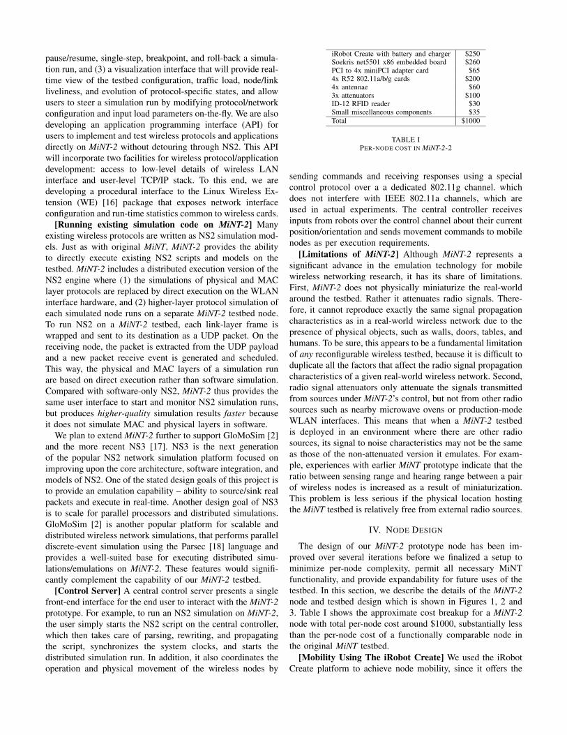
iRobot Create with battery and charger $250Soekris net5501 x86 embedded board $260PCI to 4x miniPCI adapter card $654x R52 802.11a/b/g cards $2004x antennae $603x attenuators $100ID-12 RFID reader $30Small miscellaneous components $35Total $1000
TABLE IPER-NODE COST IN MiNT-2-2
sending commands and receiving responses using a specialcontrol protocol over a a dedicated 802.11g channel. whichdoes not interfere with IEEE 802.11a channels, which areused in actual experiments. The central controller receivesinputs from robots over the control channel about their currentposition/orientation and sends movement commands to mobilenodes as per execution requirements.
[Limitations of MiNT-2] Although MiNT-2 represents asignificant advance in the emulation technology for mobilewireless networking research, it has its share of limitations.First, MiNT-2 does not physically miniaturize the real-worldaround the testbed. Rather it attenuates radio signals. There-fore, it cannot reproduce exactly the same signal propagationcharacteristics as in a real-world wireless network due to thepresence of physical objects, such as walls, doors, tables, andhumans. To be sure, this appears to be a fundamental limitationof any reconfigurable wireless testbed, because it is difficult toduplicate all the factors that affect the radio signal propagationcharacteristics of a given real-world wireless network. Second,radio signal attenuators only attenuate the signals transmittedfrom sources under MiNT-2’s control, but not from other radiosources such as nearby microwave ovens or production-modeWLAN interfaces. This means that when a MiNT-2 testbedis deployed in an environment where there are other radiosources, its signal to noise characteristics may not be the sameas those of the non-attenuated version it emulates. For exam-ple, experiences with earlier MiNT prototype indicate that theratio between sensing range and hearing range between a pairof wireless nodes is increased as a result of miniaturization.This problem is less serious if the physical location hostingthe MiNT testbed is relatively free from external radio sources.
IV. NODE DESIGN
The design of our MiNT-2 prototype node has been im-proved over several iterations before we finalized a setup tominimize per-node complexity, permit all necessary MiNTfunctionality, and provide expandability for future uses of thetestbed. In this section, we describe the details of the MiNT-2node and testbed design which is shown in Figures 1, 2 and3. Table I shows the approximate cost breakup for a MiNT-2node with total per-node cost around $1000, substantially lessthan the per-node cost of a functionally comparable node inthe original MiNT testbed.
[Mobility Using The iRobot Create] We used the iRobotCreate platform to achieve node mobility, since it offers the

Fig. 1. Physical layout of a MiNT-2 node. Fig. 2. Picture of a MiNT-2 node. Fig. 3. Picture of the MiNT-2 testbed. RFID cardsare marked red.
full range of motion we require – forwards, backwards, in anarc, or in-place rotation – and includes an easily-interfacedserial control protocol. The Create is a developer-friendlyrobot, which differs from the commercial Roomba roboticvacuuming robot used in the prior MiNT testbed in that itprovides a much more complete interface for controlling therobot. One of our goals was to eliminate the external batterynecessary in previous wireless testbeds to power the embeddedcontroller board, so we looked only at boards capable ofrunning on the 15V, 1.5A unregulated voltage supplied by therobot. The embedded board used direct serial control to issuecommands to and read sensor data from the robot. The robothas full freedom of 2-dimensional movement. Each Create canmove forward and backwards at velocities between 1 and 500mm/s in increments of 1mm/s, turn in place, and move inforward and backward arcs from 1 to 2000mm in radius insteps of 1mm. The robot, besides functioning as the mobilitycomponent of each node, provides three classes of connectionsfrom a DB-25 connector on the inside of its cargo bay: a57,600-baud bidirectional control interface, an unregulated 15volt (1.5 amps) power for the embedded board, and 5 volts(100 milliamps) to power an external RFID reader chip. Wedescribe these in detail later.
[Embedded Control Board] From the beginning of thedesign process, we assumed several minimum requirementsfor the embedded board to be mounted on each node. Firstand foremost, it needed to have sufficient computing powerto run full-fledged unmodified networking applications andsimulation packages, such as NS2, and needed to support amodern distribution of Linux. Secondly, it needed an RS232serial port to interface with the robot, and later, a second serialport to receive data from the RFID reader in each node. Italso needed to consume relatively little power, and accept avariable-voltage power supply. Thus, a board with a built-involtage regulator was preferable. In addition, we wanted toeliminate the hard drive used in the original MiNT testbed andrely solely on flash-based memory such as Compact Flash(CF) or Secure Digital (SD) cards [19]. Finally, to performmultiple-channel simulations and provide future expandability,we wanted at least four wireless interfaces per node.
The Soekris net5501 board met our specifications, provided
additional features, and supported a functional Linux operatingsystem. The net5501 is built around an x86 compatible AMDGeode processor running at 433MHz with 256MB of RAM, aCompact Flash slot, a single miniPCI slot, and a PCI riser slot.By adding a PCI expansion card, we were able to connect fouradditional miniPCI wireless cards for a total of five wirelessinterfaces. The Voyage Linux distribution worked out of thebox, and with some basic setup, the Madwifi drivers built intoVoyage for Atheros wireless cards recognized and initializedall five wireless interfaces. The Soekris board can accept 5to 25V DC, and draws well under the 27-watt maximumcontinuous power that the iRobot Create can provide.
[Automatic Node Recharging] Create robots are designedto use a docking station to self-charge their batteries. Thedocking station emits an IR beacon that enable a Create robotwith depleted batteries to home in to the station automaticallyand recharge. In the MiNT-2 prototype, the net5501 embeddedboard is powered using Create’s own battery, as opposedto the earlier MiNT prototype which required a separateuniversal laptop battery to power the onboard computer. Wereverse engineered the level-shifting circuitry of Create so thatthe net5501 board can be powered using Create’s internalpower source. Unlike the Roomba robot used in earlier MiNTprototype, the Create robot in MiNT-2 provides an interfaceto probe the residual charge in its battery. We use a residualbattery capacity estimation algorithm to track the battery statusand to determine when to recharge which nodes. Section VIprovides details on both the charge estimation algorithm andbattery performance.
[Wireless Setup] Each node needs at least two communi-cations interfaces: one for node control and one or more fordata exchange. The control interface is used to communicatebetween the controller node and each individual node, whilethe data interfaces are used to communicate with other nodesduring experimentation. Bluetooth, 802.11a, and 802.11b/gwere considered for the control and data interfaces. We deter-mined that 802.11a would be best used for data channel dueto higher bandwidth and less interference with the 2.4 GHzspectrum, leaving either 802.11b/h free for control. The R52is a low-power miniPCI wireless card supporting 802.11a/b/gbased on the Atheros AR5414 chipset. It requires Madwifi
drivers, that are included by default in Voyage Linux. Whilethe four wireless interfaces in each node are intended primarilyto experiment with multiple channel protocols and MIMOcapabilities, other possible uses include using each physicalnode as up to four virtual nodes. Virtualizing nodes wouldpermit four times as many wireless clients to be simulatedin the testbed, with the caveat that each of the virtual clientscontained in a physical node would be in the same physicallocation at all times.
[Miniaturization of Radio Channel] The maximum trans-mit power of each R52 card used in our testbed is 65mW.Two methods are paired to reduce this power and thus limitthe range of the card: electrically attenuating the antennaconnection, and reducing the transmission power in software.The iwconfig utility built into Voyage Linux allows a reductionin transmission power down to 1mW, but as observed in theearlier MiNT prototype [20], this does not sufficiently limiteach node’s range. The physical space requirement of theMiNT-2 testbed is further reduced by inserting a radio signalattenuator [14] between the WLAN interface and its antennaon each mobile node. The attenuators [14] used are the same asin the original MiNT testbed to further reduce the low 65mWtransmit power of the wireless cards. By combining hardwareand software attenuation control, we are able to adjust therange of each wireless interface at a fine granularity. Eachmini-PCI WLAN card on the net5501 board is connected to a2dBi external antenna through a 22dB attenuator. This adds atotal of 44dB attenuation on the signal path from transmitterto receiver and thus makes it possible to deploy the MiNT-2 prototype within a small space. In addition to the fixedattenuation, the transmit power on the mini-PCI cards can bealtered by another 20dBm to provide additional flexibility intuning inter-node signal to noise ratio. Since a radio signalattenuator reduces the strength of the input signal and relaysthe result to its output completely in the analog domain, itdoes not incur any observable performance overhead.
V. NODE LOCALIZATION
The goal of localization is to allow a node to accuratelydetermine its own absolute position and orientation as wellas that of other robots in the testbed. The Roomba robotsused in the original MiNT prototype could not sense theirown positions. As a result, they relied exclusively on the cen-tral controller which used a vision-based position/orientationtracking system consisting six ceiling-mounted webcams withoverlapping image planes. This system was used to tracknode location and to command the robots on which directionto move at any instant. To account for growing discrepancyover time between the central controller’s per-node positioninformation and the actual node positions, periodically mo-bile robots were manually brought to fixed locations to re-synchronize their logical and physical node positions. Eachnode was identified using unique color patches mounted on themobile nodes. Since this system relied on visual identification,it tended to develop inaccuracies over time if any of the sixcameras are moved slightly, or color patterns on the nodes
faded, or lighting varied. We redesigned the localization mech-anism from scratch in the MiNT-2 testbed to overcome thelimitations of its predecessor. Our new localization mechanismuses inexpensive RFID technology coupled with enhancedmobility sensors within the Create robot to reduce maintenanceoverheads, which helps to achieve high levels of accuracy.
[Localization Hardware] Our localization infrastructurehas three components. First, the robot’s wheel motors can becontrolled in terms of distance per second, and each wheel’sspeed can be varied in integer steps between -500mm/s and500mm/s. This system by itself may accumulate error overtime from mechanical variation, and also fails to take intoaccount mechanical acceleration and deceleration after startand stop commands are issued. To detect and correct forthese inaccuracies, at the second level, each of the robot’stwo driving wheels includes an axle-mounted rotation sensorthat measures the actual distance each wheel has traveled.The sensors can be queried via the serial interface, and returnboth distance traveled by the robot since the last query (inmm) and angle the robot has rotated through since the lastquery (in degrees). Over time, even the accumulated sensormeasurements may grow inaccurate due to rounding errors,wheel slippage, and encoder inaccuracy. In addition, a nodemay be manually picked up and moved to a new location.Thus a third absolute positioning system is therefore neededto periodically re-calibrate the node’s position and orientationin the testbed space. We considered a wide assortment oflocalization technologies before settling on RFID as the mostcost-effective and sufficiently accurate method.
[RFID-based Localization Algorithm] An array of fixedRFID tags on the floor of the testbed allow each robot todetermine its absolute location with an uncertainty equal tothe maximum tag sensing radius of the RFID reader. Wemounted ID-12 RFID reader at the base of each node’s cargobay, soldered it to a breakout board, and wired it via a DB-10 connector to the internal serial connection of the net5501embedded board. The RFID reader is used to determine thenode’s absolute (x, y) position within the testbed by matchingthe IDs of the RFID tags with a static translation table ofID to coordinates, corrects for errors in the sensors andcompensates for extraneous interactions such as hitting anobstacle or researchers lifting and manually relocating thenodes. The localization system is currently implemented asa set of functions detailed below, with preliminary accuracymeasurements presented later.
The heart of the localization algorithm is a section of coderunning periodically every 50ms that is in charge of acquisitionand processing of data from movement sensors and the RFIDreader. Figure 4 presents a more structured view of thelocalization algorithm. Every time the localization tick runs,it reads the delta change in distance and orientation since thelast sensor access, adds the changes to the last known positionand orientation respectively, and clears the sensors. In addition,more precise position and orientation calibration is performedwhen passing over RFID tags to remove accumulated errorfrom the Create’s sensors feedback. RFID data is considered

Localize_Tick
Obstacle
at last
tick?
Yes
No
Back up Stop
Reset SensorsSet obstacle flag
Destination
Flag?
Yes
No
Destination
motor adjustment
Read Sensors
Update
x, y, theta
RFID tag
read?
Yes
No
Complete.
Set previous and
current RFID
x, y with offset
Obstacle
since last
RFID?
Yes
No
Calculate
orientation
from RFID
Calculate
orientation
from sensors
Fig. 4. Scheduled localization tick functionality.
more authoritative than sensor data, and has priority wheneverinformation from the sensor and the RFID sources disagree.Once at least two tags have been read, the node can determineits orientation from the coordinates of each tag, its orientationat the first tag, and the amount of node rotation between thefirst and second tags.
A node may move from one tag to the next in a variety ofways. If the node moved in a straight line or arc of constantradius, the RFID data is used to calculate the node’s headingat the second tag. The orientation at the second tag can becalculated using the current (x2, y2) position read from thecurrent tag, the position (x1, y1) at the previous tag, andthe node’s rotation between the two tags as measured by itssensors, ∆θRFID:
θ = (tan−1[(y2 − y1)/(x2 − x1)] + ∆θRFID/2) mod 360(1)
If the node travels in a straight line, then ∆θRFID is 0 and theequation reduces to the trivial case. If it traveled in a constant-radius arc, its deviation from the straight line path betweenthe two tags is equal in magnitude at both tags, but oppositein sign. Thus its rotation between the two tags is twice theindividual magnitude of deviation from a straight- line pathat each tag, and current orientation can be determined whilediscarding all orientation data up to the first of the two tags. Asonly the change in rotation between the two tags is retained,
accumulated inaccuracy from the onboard rotation sensors isdiscarded each time this calculation is performed.
If instead the robot travels from one tag to the next inan arc of non constant radius or encounters any obstaclesbetween the two sequential tags, the RFID data is only usedto determine position, and node orientation is calculated usingthe incremental change in rotational sensor reading sincethe last localization tick. Also, the structure of a MiNTnode itself slightly complicates localization because the RFIDreader cannot be placed exactly at the center of the node.The internal sensors return data most accurate at the pointhalfway between the robot’s two axles, but the RFID readeris located 147mm behind this point. To compensate for thisoffset, the sensor-derived position information is combinedwith the (x, y) coordinate of the RFID tag to calculate theactual position of the center of the robot. Future modificationsto the node design are accommodated by maintaining twoconstants, RFIDOnAxis and RFIDOffAxis, containing thedistance in mm from the center of the robot to the center ofthe RFID reader parallel and perpendicular to the direction offorward motion, respectively.
[Initial Node Calibration] Our goal in MiNT-2 is to com-pletely automate the steps of calibration and initial positioningand of the nodes. Accurate calibration means that the testbedoperator can drop each robot anywhere in the testbed andthe robot automatically positions itself at a nearest referencepoint with known orientation. Following calibration, the nodethen automatically moves to an initial position/orientationspecified in the experimental scenario. The calibration stepof each node’s position and orientation is performed bytraversing the testbed in a series of straight lines. If a nodereaches an obstacle, such as a wall or another robot, it rotatesthrough a 190-degree angle and attempts another straight linemovement. Calibration is only considered successful if thenode reads two RFID tags over a straight line movement, toeliminate any possible error from inaccuracy in the rotationand movement at an obstacle. Correct calibration of positionis further complicated by the off-center RFID reader, but theoffset is handled by the localization tick as detailed in theprevious section. Orientation can be correctly calculated fromtwo collinear RFID tags regardless of the node’s offset, butaccurate position determination taking the RFID reader offsetinto account requires the authoritative heading of the nodeto be predetermined. Thus, after passing the second tag thenode’s orientation is calculated from the tabulated positionsof the two RFID tags, then its proper position is determinedfrom the tabulated position of the second RFID tag correctedwith an offset calculated from the now-initialized heading.Once initialization of both position and orientation is complete,the node stops and is ready to receive an initial position fora simulation scenario. Given that the first RFID tag crossedis at (x1, y1) and the second is at (x2, y2), the position and

orientation at the second tag are:
θ = arctan[(y2 − y1)/(x2 − x1)] (2)x = x2 + RFIDOnAxis cos(θ) + RFIDOffAxis sin(θ) (3)y = y2 + RFIDOnAxis sin(θ) + RFIDOffAxis cos(θ) (4)
For our nodes’ construction, RFIDOnAxis, was 147mm andRFIDOffAxis was 0mm.
[Network Layout Initialization] Before a scenario execu-tion, the user can specify the topology as well as the nodelocations of the target network. After calibration, each nodethen travels to the user-specified initial position and orientsitself in a specific direction before an experimental scenariobegins. User can also modify the initial location of a nodeand have the controller instructs the corresponding robot tomove accordingly. During this process, every testbed node isconstantly measuring the radio signal strength between itselfand each of its neighbors within hearing range, and relayingthe information to the central controller, which then feedsit back to the user. Such interactive initial placement andfeedback greatly simplifies the network setup effort becausethe administrator no longer needs to manually move the robots.
We also plan to to take this network initialization onestep further: the user can simply specify the pair-wise signalstrength requirements, and the system can either automaticallyplace the testbed nodes so as to satisfy all the pair-wise signalstrength constraints, or if the user-specified requirement isover-constrained, the system will report that the requirementis infeasible and request further user inputs. This problemis similar in spirit to the placement and routing algorithmsused in VLSI layout, which also operates under variousconstraints such as timing, as opposed to the signal to noiseratio in our case. It is unlikely that any algorithm can get thisright in one shot. Rather we would like to identify a goodinitial solution, and fine-tune it dynamically through roboticmovement according to actual signal strength measurements.
VI. PERFORMANCE
A. Battery Performance
Figure 5 shows the results of battery tests and reveals thatnode longevity matches worst-case measurements for othertestbeds. Note that only data for the standard battery has beenpresented because node life did not vary significantly betweenthe standard and extended batteries from iRobot, presumablydue to the presence of embedded control board. Nodes areable to move continuously while running the Soekris boardfor 2.25 hours before the battery discharges completely. Testsperformed with static nodes transmitting constantly achieve3.6 hours of battery life. Board clock speed and node move-ment speed remain constant to the limits of the applicablesensors regardless of current battery level. The distinctiveshape of the discharge curve provides a strong indication ofimpending battery failure. As expected, motor operation claimsthe largest impact on longevity, while a single active wirelessinterface only removes twenty minutes of battery life. Multiple
Fig. 5. Standard battery life on an idle node, a continuously-transmittingnode, and a continuously-moving node.
simultaneously-active interfaces are expected to incur a lineartoll on the battery.
B. Localization
As discussed earlier, our localization mechanism uses acombination of readings obtained from distance and anglesensors mounted on the robot and pre-deployed RFID tags.Specifically, we use RFID tags to recalibrate current positionand orientation of the robot. However, since the RFID tagcan be detected by the RFID reader, immediately when itcomes in the range with the tag, (which is a circle of 2.25cm radius), the RFID tags based error calibration has amaximum error bound of 2.25 cm. In this section, we firstdescribe our experiments to measure accuracy of distance andangle sensors, and then present the results representing errorestimates for the localization algorithm.
1) Sensor Accuracy: In order to calculate error bound forthe distance sensor, we created multiple scenarios of RFIDtags by keeping them in straight line and varying distancebetween a pair of tags for different scenarios. We programmedthe node to move in a straight line such that it will encounterthe RFID tags placed along the way. The distance sensorvalue was calibrated at each encountered RFID tag and theerror was noted, where the error is the difference betweenthe (x,y) position represented by the distance sensor andthat of the detected RFID tag. In Figure 6, values along x-axis represent the distances between a pair of RFID tags fordifferent scenarios, whereas y-axis represents the error in thedistance sensor readings.
We can observe that the error in position estimates is lessthan 2 cm. However, for all the scenarios used in our setup,we did not observe an explicit trend in the estimates of errorswith respect to the increase in distance between two tags. Thedifference in the error estimates for different scenarios is dueto the mismatch between the timings of reading an RFID tagand the distance sensor (which is read every 50 millisecondsby the localization algorithm).
To calculate error bound for the angle sensor, we kept theRFID tags in a pyramid like structure and moved the robotfrom the tip to the base of the pyramid in a straight line. Theheight of the pyramid was the length of our testbed area, and
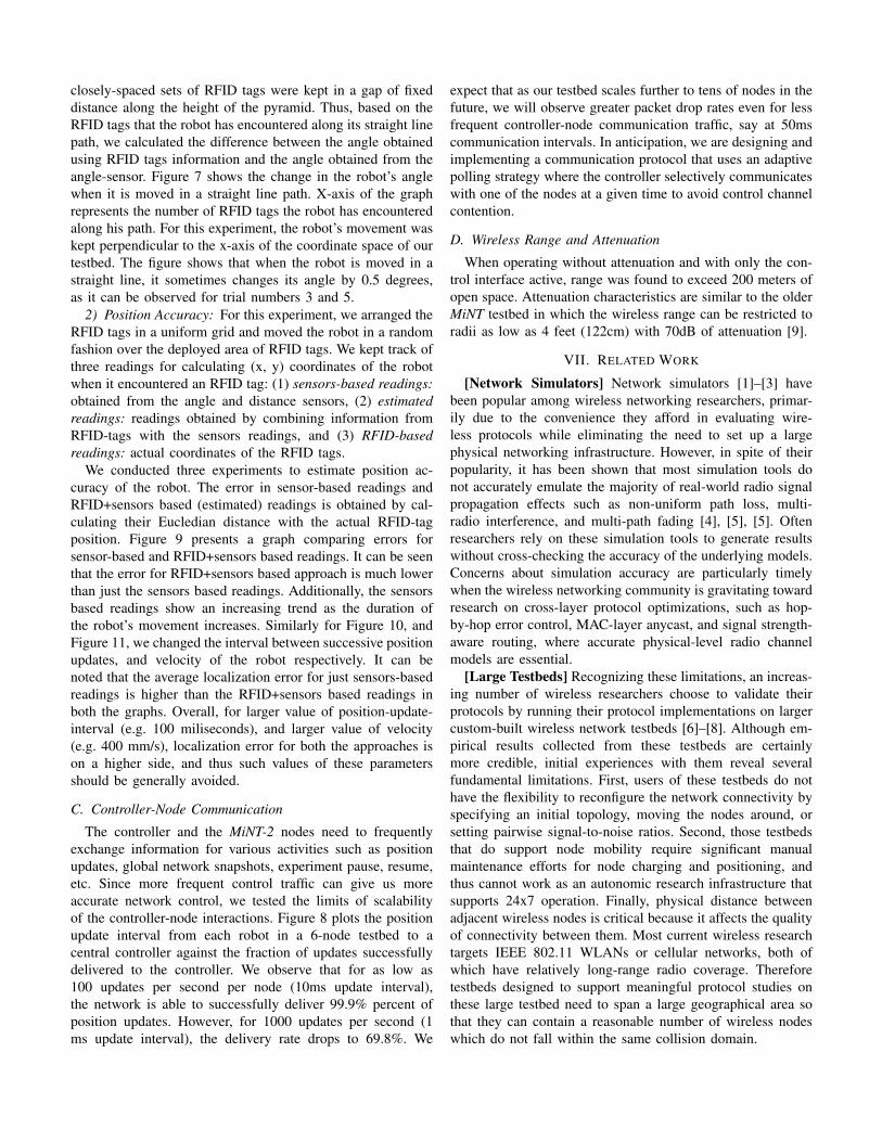
closely-spaced sets of RFID tags were kept in a gap of fixeddistance along the height of the pyramid. Thus, based on theRFID tags that the robot has encountered along its straight linepath, we calculated the difference between the angle obtainedusing RFID tags information and the angle obtained from theangle-sensor. Figure 7 shows the change in the robot’s anglewhen it is moved in a straight line path. X-axis of the graphrepresents the number of RFID tags the robot has encounteredalong his path. For this experiment, the robot’s movement waskept perpendicular to the x-axis of the coordinate space of ourtestbed. The figure shows that when the robot is moved in astraight line, it sometimes changes its angle by 0.5 degrees,as it can be observed for trial numbers 3 and 5.
2) Position Accuracy: For this experiment, we arranged theRFID tags in a uniform grid and moved the robot in a randomfashion over the deployed area of RFID tags. We kept track ofthree readings for calculating (x, y) coordinates of the robotwhen it encountered an RFID tag: (1) sensors-based readings:obtained from the angle and distance sensors, (2) estimatedreadings: readings obtained by combining information fromRFID-tags with the sensors readings, and (3) RFID-basedreadings: actual coordinates of the RFID tags.
We conducted three experiments to estimate position ac-curacy of the robot. The error in sensor-based readings andRFID+sensors based (estimated) readings is obtained by cal-culating their Eucledian distance with the actual RFID-tagposition. Figure 9 presents a graph comparing errors forsensor-based and RFID+sensors based readings. It can be seenthat the error for RFID+sensors based approach is much lowerthan just the sensors based readings. Additionally, the sensorsbased readings show an increasing trend as the duration ofthe robot’s movement increases. Similarly for Figure 10, andFigure 11, we changed the interval between successive positionupdates, and velocity of the robot respectively. It can benoted that the average localization error for just sensors-basedreadings is higher than the RFID+sensors based readings inboth the graphs. Overall, for larger value of position-update-interval (e.g. 100 miliseconds), and larger value of velocity(e.g. 400 mm/s), localization error for both the approaches ison a higher side, and thus such values of these parametersshould be generally avoided.
C. Controller-Node Communication
The controller and the MiNT-2 nodes need to frequentlyexchange information for various activities such as positionupdates, global network snapshots, experiment pause, resume,etc. Since more frequent control traffic can give us moreaccurate network control, we tested the limits of scalabilityof the controller-node interactions. Figure 8 plots the positionupdate interval from each robot in a 6-node testbed to acentral controller against the fraction of updates successfullydelivered to the controller. We observe that for as low as100 updates per second per node (10ms update interval),the network is able to successfully deliver 99.9% percent ofposition updates. However, for 1000 updates per second (1ms update interval), the delivery rate drops to 69.8%. We
expect that as our testbed scales further to tens of nodes in thefuture, we will observe greater packet drop rates even for lessfrequent controller-node communication traffic, say at 50mscommunication intervals. In anticipation, we are designing andimplementing a communication protocol that uses an adaptivepolling strategy where the controller selectively communicateswith one of the nodes at a given time to avoid control channelcontention.
D. Wireless Range and Attenuation
When operating without attenuation and with only the con-trol interface active, range was found to exceed 200 meters ofopen space. Attenuation characteristics are similar to the olderMiNT testbed in which the wireless range can be restricted toradii as low as 4 feet (122cm) with 70dB of attenuation [9].
VII. RELATED WORK
[Network Simulators] Network simulators [1]–[3] havebeen popular among wireless networking researchers, primar-ily due to the convenience they afford in evaluating wire-less protocols while eliminating the need to set up a largephysical networking infrastructure. However, in spite of theirpopularity, it has been shown that most simulation tools donot accurately emulate the majority of real-world radio signalpropagation effects such as non-uniform path loss, multi-radio interference, and multi-path fading [4], [5], [5]. Oftenresearchers rely on these simulation tools to generate resultswithout cross-checking the accuracy of the underlying models.Concerns about simulation accuracy are particularly timelywhen the wireless networking community is gravitating towardresearch on cross-layer protocol optimizations, such as hop-by-hop error control, MAC-layer anycast, and signal strength-aware routing, where accurate physical-level radio channelmodels are essential.
[Large Testbeds] Recognizing these limitations, an increas-ing number of wireless researchers choose to validate theirprotocols by running their protocol implementations on largercustom-built wireless network testbeds [6]–[8]. Although em-pirical results collected from these testbeds are certainlymore credible, initial experiences with them reveal severalfundamental limitations. First, users of these testbeds do nothave the flexibility to reconfigure the network connectivity byspecifying an initial topology, moving the nodes around, orsetting pairwise signal-to-noise ratios. Second, those testbedsthat do support node mobility require significant manualmaintenance efforts for node charging and positioning, andthus cannot work as an autonomic research infrastructure thatsupports 24x7 operation. Finally, physical distance betweenadjacent wireless nodes is critical because it affects the qualityof connectivity between them. Most current wireless researchtargets IEEE 802.11 WLANs or cellular networks, both ofwhich have relatively long-range radio coverage. Thereforetestbeds designed to support meaningful protocol studies onthese large testbed need to span a large geographical area sothat they can contain a reasonable number of wireless nodeswhich do not fall within the same collision domain.

0 10 20 30 40 50 60 70
Distance Between Tags (centimeters)0
5
10
15
20
25
30
35
40
45
50
Posi
tion
Err
or (
in m
ilim
eter
s)
Fig. 6. Error estimate for distance sensor.
1 2 3 4 5
Trial Number89.4
89.5
89.6
89.7
89.8
89.9
90
90.1
90.2
90.3
90.4
90.5
Ang
le (
degr
ees)
Fig. 7. Error estimate for angle sensor
1 10 100 1000
Position Updates Per Second65
70
75
80
85
90
95
100
Succ
essf
ul D
eliv
ery
Rat
e (%
)
Fig. 8. Impact of control channel traffic on packetdelivery rate.
0 100 200 300 400 500Time (s)
0
250
500
750
1000
1250
Dis
tanc
e E
rror
(m
ilim
eter
s)
Sensor OnlyRFID + Sensor based
Fig. 9. Errors in sensor-only vs. RFID+sensor-based localization with time.
50 60 70 80 90 100Time interval between position updates (in miliseconds)
0
200
400
600
800L
ocal
izat
ion
Err
or (
mili
met
er) Sensor Only
RFID+Sensor based
Fig. 10. Errors in sensor-only vs. RFID+sensor-based localization with update frequency.
100 150 200 250 300 350 400Velocity (mm/sec)
0
100
200
300
400
500
Err
or (
mili
met
ers)
Sensor onlyRFID+Sensor based
Fig. 11. Errors in sensor-only vs. RFID+sensor-based localization with node velocity.
[Small-Scale Testbeds] Among other existing wireless net-work testbeds, Orbit [21], [22] and Emulab [15], [23] are mostsimilar to MiNT-2. In contrast to MiNT-2, which performsradio signal attenuation, Orbit uses explicit noise injectionto control the signal-to-noise ratios between selected pairsof nodes. This approach cannot scale to a large number ofpairs because it may be impossible to generate an externalnoise profile that can simultaneously satisfy the signal-to-noiseratio requirements of all active pairs. Emulab did not attemptto solve the problem of setting up a multi-collision-domainnetwork within a small physical space. MiNT-2 also providestrue node mobility and autonomic 24x7 testbed operation. Onthe other hand, Orbit “simulates” node mobility by migratingthe simulation process for the mobile node from one physicalnode to another. Because Orbit’s nodes are organized as afixed grid, the node mobility pattern that Orbit can supportis less flexible than MiNT-2. Mobile Emulab [15] also usesmobile robots to support node mobility but requires frequentmanual recharging. Furthermore, all the above testbeds lackthe mechanism to inject controlled distributed faults into awireless environment to determine the effect of malfunctionsand failures. Moreover, the other testbeds’ robotic platformsmust be manually taken to their charging stations every 2-3hours. The iRobot Create comes with a high capacity batteryand an automatic charging dock, as well as a serial level-shifter that can be easily modified for our purposes, makingthe Create a particularly cost-effective solution.
[Localization] There is a large body of work [24] onlocalization in the context of ubiquitous computing, location-
aware services and robotics research. Our focus in the MiNT-2testbed has been on developing a simple, inexpensive, andpractical localization technique for robots used in wirelessprotocol development and testing context. We consideredactive and passive infrared triangulation as well as an infraredversion of the Stony Brook vision system that would usepatterns of infrared LEDs instead of colors to identify eachrobot and provide its location and heading. MIT’s Cricketultrasonic localization [25] was also considered. However thecost of these systems combined with the significant associatedcomputation burden rendered it unsuitable for our application.A pressure-based system called SmartFloor [26] would nothave been able to differentiate between the nodes, althoughit is well-suited to determine the precise location of eachnode. The earlier MiNT prototype [20] solved the localizationproblem through visual recognition of a unique color patternon top of each robot with a distributed webcam-based imageprocessing system. However, over time, some shortcomings ofusing visual identification were found. For example, the systemcan quickly develop inaccuracies if any of the six camerasare moved slightly, the color patterns fade, or lighting varies.Mobile Emulab [23] also uses an similar vision based imageprocessing technique for localization, using two color patternon top of each robot. However two color patterns cannot helpidentify the robots individually. To overcome this problemone needs to keep track of movement patterns for each robotand maintain an association between robot’s identificationand its current location as observed by the camera network.

MiNT-2 nodes do not run into these problems because aninexpensive RFID reader is mounted on each robot and thusthe node itself can detect/compute its location without relyingon an external entity for identification. RFID based localizationtechniques have also proven effective in other contexts forboth large-scale localization [27] and more limited table-sizedapplications [28].
VIII. SUMMARY AND FUTURE WORK
In this paper, we described the improved testbed design andlocalization techniques in MiNT-2 – a ground-up re-design ofthe predecessor MiNT project from Stony Brook. Our visionis to simplify the architecture for designing a fully functionalminiaturized wireless protocol development and testing plat-form, so that any networking research group in the worldcan easily set up such a testbed using commodity hardwareand open-source software. Each node in MiNT-2 is comprisedof an iRobot Create providing mobility to the node, an ID-12 RFID reader performing localization, a Soekris net5501x86-compatible embedded board directing the robot, and fivewireless network interfaces with attenuators and antennaefor control and communication. Node localization system isimplemented using robots internal sensor and external RFIDdata, including the functionality to automatically calibrateeach node’s position and initialize initial network setup. Thetestbed took slightly more than two months to design andconstruct from scratch into a working form (including waitingfor shipment of parts), and per-node cost has been kept toaround $1000, even though cost reduction was not the primaryobjective. Improvements to the MiNT-2 testbed are ongoing.Our next steps are to develop improved coordination betweeneach node and the a central controller, port the hybrid NS2software built by Stony Brook to MiNT-2, and develop a fullfeatured fault injection, analysis, and debugging toolkit forprotocol development and testing. More information about theMiNT-2 project can be found online [?].
ACKNOWLEDGMENT
We’d like to thank the Stony Brook’s MiNT group for theiractive support in helping construct MiNT-2 from scratch. Thiswork is supported in part by the National Science Foundationthrough grants CNS-0751161 and CCF-0649252.
REFERENCES
[1] Information Sciences Institute, “The Network Simulator – NS-2http://www.isi.edu/nsnam/ns/.”
[2] X. Zeng, R. Bagrodia, and M. Gerla, “GloMoSim: A Library for ParallelSimulation of Large-Scale Wireless Networks,” in Workshop on Paralleland Distributed Simulation, May 1998.
[3] Scalable Network Technologies Inc., “QualNet WiFi simulator,” inhttp://www.scalable-networks.com/products/qualnet wifi.php, 2004.
[4] M. Takai, J. Martin, and R. Bagrodia, “Effects of Wireless PhysicalLayer Modeling in Mobile Ad Hoc Networks,” in Proceedings ofMobiHoc, Oct 2001.
[5] J. Heidemann, N. Bulusu, and J. Elson, “Effects of detail in wirelessnetwork simulation,” in SCS Multiconference on Distributed Simulation,January 2001.
[6] D. Maltz, J. Broch, and D. Johnson, “Experiences Designing andBuilding a Multi-Hop Wireless Ad-Hoc Network Testbed,” in TechnicalReport 99-116, School of Computer Science, CMU, Mar 1999.
[7] H. Lunndgren, D. Lundberg, J. Nielsen, E. Nordstrom, and C. Tscudin,“A Large-scale Testbed for Reproducible Ad Hoc Protocol Evaluations,”in Proceedings of Wireless Communications and Networking (WCNC),2002.
[8] Daniel Aguayo et al., “MIT Roofnet Implementationhttp://www.pdos.lcs.mit.edu/roofnet/design/,” August 2003.
[9] P. De, A. Raniwala, S. Sharma, and T. cker Chiueh, “Mint: A miniatur-ized network testbed for mobile wireless research,” In Proceedings ofIEEE Infocom, 2005.
[10] P. De, “Mint: A reconfigurable mobile muli-hop wireless networktestbed,” Ph.D. dissertation, Stony Brook University, 2007.
[11] J. Luck and J. Ioannidis, “Roomba Internals,” inhttp://www.tla.org/roomba/1disass.html, January 2003.
[12] iRobot Corporation, “iRobot create programmable robot,http://www.irobot.com/sp.cfm?pageid=305.”
[13] A. Raniwala, K. Gopalan, and T. cker Chiueh, “Centralized ChannelAssignment and Routing Algorithms for Multi-Channel Wireless MeshNetworks,” in ACM SIGMOBILE Mobile Computing and Communica-tions Review, April 2004.
[14] Honeywell, “High Performance Attenuator Introductionhttp://www.ssec.honeywell.com/microwave/appnotes/Ap Note 4511.pdf,” May 2002.
[15] D. Johnson, T. Stack, R. Fish, D. Flickinger, L. Stoller, R. Ricci, andJ. Lepreau, “Mobile Emulab: A Robotic Wireless and Sensor NetworkTestbed,” in Proceedings of IEEE INFOCOM 2006, April 2006.
[16] J. Tourrilhes, “Wireless Tools for Linuxhttp://www.hpl.hp.com/personal/Jean Tourrilhes/Linux/Tools.html,”May 2004.
[17] T. R. Henderson, S. Roy, S. Floyd, and G. F. Riley, “The NS-3 Projecthttp://www.nsnam.org/.”
[18] R. Bagrodia, R. Meyer, M. Takai, Y. Chen, X. Zeng, J. Martin, B. Park,and H. Song, “Parsec: A Parallel Simulation Environment for ComplexSystems,” IEEE Computer, vol. 31, no. 10, pp. 77–85, October 1998.
[19] P. De, A. Raniwala, S. Sharma, and T. cker Chiueh, “Design consider-ations for a multi-hop wireless network testbed,” IEEE CommunicationMagazine, Oct 2005.
[20] P. De, R. Krishnan, A. Raniwala, K. Tatavarthi, N. A. Syed, J. Modi,and T. cker Chiueh, “Mint-m: An autonomous mobile wireless experi-mentation platform,” In Proceedings of Mobisys, 2006.
[21] D. Raychaudhuri, “ORBIT: Open-Access Research Testbed for Next-Generation Wireless Networks,” in As proposal submitted to NSFNetwork Research Testbeds Program, May 2003.
[22] D. Raychaudhuri, I. Seskar, M. Ott, S. Ganu, K. Ramachandran,H. Kremo, R. Siracusa, H. Liu, and M. Singh, “Overview of the ORBITRadio Grid Testbed for Evaluation of Next-Generation Wireless NetworkProtocols,” in Proc. of WCNC, Mar 2005.
[23] B. White, J. Lepreau, L. Stoller, R. Ricci, S. Guruprasad, M. Newbold,M. Hibler, C. Barb, and A. Joglekar, “An integrated experimentalenvironment for distributed systems and networks,” in Proc of OSDI’02,Boston, MA, Dec. 2002, pp. 255–270.
[24] J. Hightower and G. Borriello, “Location systems for ubiquitous com-puting,” Computer, vol. 34, no. 8, pp. 57–66, Aug 2001.
[25] N. B. Priyantha, A. Chakraborty, and H. Balakrishnan, “The cricketlocation-support system,” in MobiCom ’00: Proceedings of the 6thannual international conference on Mobile computing and networking.New York, NY, USA: ACM, 2000, pp. 32–43.
[26] R. J. Orr, “SmartFloor, http://www.cc.gatech.edu/fce/smartfloor/.”[27] J. Bohn, “Prototypical implementation of location-aware services based
on a middleware architecture for super-distributed rfid tag infrastruc-tures,” Personal Ubiquitous Comput., vol. 12, no. 2, pp. 155–166, 2008.
[28] S. Hinske and M. Langheinrich, “An RFID-based Infrastructure for Au-tomatically Determining the Position and Orientation of Game Objectsin Tabletop Games.”