testing machines and testing systems for metals
TRANSCRIPT

Testing Machines and Testing Systems for Metals
BB
253
.2.0
3.15
Testing systems
Intelligent testing

2
2 Testing MetalsContents Page
2.1 Overview of metals testing 5
2.2 Heavy plate 6
2.3 Strip and sheet 10
2.4 Thin sheet 12
2.5 Bars and rods 15
2.6 Sections/profiles and reinforcing steel 17
2.7 Wire and cable 20
2.8 Pipes 22
2.9 Castings and forgings 24
2.10 Fasteners 25
3 Metals Testing Products and ServicesContents Page
3.1 Specimen preparation and dimensional measurement 27
3.2 Electromechanical testing machines 28
3.3 Hardness testing machines and instruments 31
3.4. Tests at high temperature 34
3.5 Creep testing machines 35
3.6 Fatigue testing machines 36
3.7 Sheet metal testing machines 37
3.8 Pendulum impact testers 38
3.9 High-speed testing machines and drop-weight testers 39
3.10 Robotic testing systems 40
3.11 testXpert II - the new generation of materials testing software 42
3.12 Load cells 43
3.13 Specimen grips 44
3.14 Extensometers 45
3.15 Service from start to finish 46
3.16 Modernization of testing systems 47
1 The Zwick Roell Group of CompaniesContents Page
1.1 With passion and expertise 3
1.2 Your dependable metals testing partner 4
4 Overview of StandardsAn overview of all relevant standards for metals testing can be found at www.zwick.com/en/applications/metals/standards

3
Zw
ick
Ro
ell G
roup
Ap
plic
atio
nsP
rod
ucts
1.1 Zwick – with passion and competence
"Passion in customer orientation." If anyone asks about our corporate philosophy – that is our reply! The fact that over a third of our em-ployees are engaged in service and support shows that these are far from being empty words.
As a family-run concern with a tradi-tion stretching back 160 years we place great value on honesty and fairness. Over the years an ethos of close collaboration based on mutual trust between our partners, sup-pliers and customers has evolved, something that we all value highly.
Always at your serviceOver 850 people work at our headquarters in Ulm alone. Many of them have been with us for years – decades even. Their knowledge, ability and commitment are what lies behind the worldwide success of the Zwick/Roell Group
We are present in over 50 countries around the world.
The right solutionsWhether for static materials testing or the various forms of fatigue testing – we have the right solutions. We have products for hardness testing, instruments for impact testing and for sheet-metal testing.
And for that rare occasion when we don’t have a solution to fit, our experts will find one – from the smallest adapta-tion right through to a fully automated testing system or a test stand for special purposes
The basis of a successful partnership: innovative employees, innovative products!
Fig.1: Innovations Center at Zwick's headquarters in Ulm, Germany
4
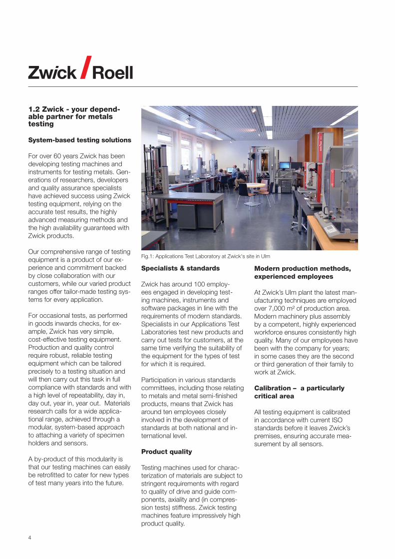
Fig.1: Applications Test Laboratory at Zwick's site in Ulm
1.2 Zwick - your depend-able partner for metals testing
System-based testing solutions
For over 60 years Zwick has been developing testing machines and instruments for testing metals. Gen-erations of researchers, developers and quality assurance specialists have achieved success using Zwick testing equipment, relying on the accurate test results, the highly advanced measuring methods and the high availability guaranteed with Zwick products.
Our comprehensive range of testing equipment is a product of our ex-perience and commitment backed by close collaboration with our customers, while our varied product ranges offer tailor-made testing sys-tems for every application.
For occasional tests, as performed in goods inwards checks, for ex-ample, Zwick has very simple, cost-effective testing equipment. Production and quality control require robust, reliable testing equipment which can be tailored precisely to a testing situation and will then carry out this task in full compliance with standards and with a high level of repeatability, day in, day out, year in, year out. Materials research calls for a wide applica-tional range, achieved through a modular, system-based approach to attaching a variety of specimen holders and sensors.
A by-product of this modularity is that our testing machines can easily be retrofitted to cater for new types of test many years into the future.
Specialists & standards
Zwick has around 100 employ-ees engaged in developing test-ing machines, instruments and software packages in line with the requirements of modern standards. Specialists in our Applications Test Laboratories test new products and carry out tests for customers, at the same time verifying the suitability of the equipment for the types of test for which it is required.
Participation in various standards committees, including those relating to metals and metal semi-finished products, means that Zwick has around ten employees closely involved in the development of standards at both national and in-ternational level.
Product quality
Testing machines used for charac-terization of materials are subject to stringent requirements with regard to quality of drive and guide com-ponents, axiality and (in compres-sion tests) stiffness. Zwick testing machines feature impressively high product quality.
Modern production methods, experienced employees
At Zwick’s Ulm plant the latest man-ufacturing techniques are employed over 7,000 m² of production area. Modern machinery plus assembly by a competent, highly experienced workforce ensures consistently high quality. Many of our employees have been with the company for years; in some cases they are the second or third generation of their family to work at Zwick.
Calibration – a particularly critical area
All testing equipment is calibrated in accordance with current ISO standards before it leaves Zwick’s premises, ensuring accurate mea-surement by all sensors.

5
Segments of the metals industry
Flat products
Heavy plate (incl. slabs, billets)
Strip and sheet (incl. hot-rolled strip, hot-rolled wide strip)
Thin sheet (incl. tinplate, coated sheet)
Long products
Bars and rods
Sections/profiles and reinforcing steel
Wire and cable
Semi-finished products Pipes (incl. fittings)
Castings and forgings (incl. sintered metal and powdered metal items)
Fasteners (incl. welding and joining technology)
• • • • – – • • • • • – • • • –
• • • • – • • • • • – • • – – •
• – – • – • • • • – – • – – – •
• • • • • – • – – • • – • – • –
• – – • – – • • • • – – – – – –
• – – • • – • – • • • – – – – –
• • • • – – • • • • – – • • – –
• • • – • – • – – • • – • – • –
• – • • • – • • • • – – – • – –
2.1 Overview of metals testing
Type o
f te
st
Quasi
-sta
tic t
est
s
Tens
ile te
sts
at ro
om te
mpe
ratu
re
Tens
ile te
sts
at e
leva
ted
tem
pera
ture
Cre
ep te
sts
Flex
ure
and
com
pres
sion
test
s
Tors
ion
test
s
Duc
tility
test
s
Har
dnes
s te
sts
Spe
cial
met
hods
and
test
s(s
hear
test
s, w
eld-
seam
test
s)
Rob
otic
test
ing
syst
ems
Fati
gue t
est
s
Fatig
ue te
sts
Rot
atin
g ba
r be
ndin
g fa
tigue
test
s
Impact
test
s
Hig
h-sp
eed
test
s
Cha
rpy
impa
ct te
sts
Dro
p-w
eigh
t tes
ts
Fra
ctu
re m
echanic
s te
sts
Specim
en p
repara
tion
Zw
ick
Ro
ell G
roup
Ap
plic
atio
nsP
rod
ucts

6
2.2 Heavy plate
Heavy plates are steel sheets with a width of up to four meters and a thickness of at least five millimeters, up to approx. 250 mm. They are used principally in the construction industry, for heavy plant and cranes, in shipbuilding, for offshore drilling platforms and for large-diameter, thick-walled pipes.
Hardness testing
Brinell hardness testing on coarse sheet can be performed us-ing Zwick testing machines, with test loads of up to 29,430 N. The ZHU250CL universal hardness test-ing machine covers the test load range up to 2,500 N, while the use of state-of-the-art closed-loop tech-nology guarantees high reproduc-ibility and maximum precision. A fast digital industrial camera enables Brinell indentations to be transferred to a PC system with advanced eval-uation and control software.
Zwick also has instruments avail-able for portable hardness testing and for all other relevant hardness testing methods (Vickers, Rockwell etc.).
Tensile test
Tensile specimens are removed from heavy plate in such a way that the sheet thickness is retained as specimen thickness as far as possi-ble. Specimens have a correspond-ingly large cross-section, the parallel length being produced by milling. The tensile test material properties are therefore determined over a large volume and the influences of specimen production minimized.
Zwick’s wide range of standard test-ing systems up to 2,500 kN provide high-accuracy testing un-der high loads, while our hydraulic specimen grips ensure that perfect clamping and positioning of speci-mens are maintained during tests. Strain measurement is via makroX-tens or laserXtens extensometers. makroXtens represents the classi-cal solution, proven in service over many years and offering a high degree of robustness – the sensor arms remain on the specimen until after break - combined with simple operation. The sensor arms are ap-plied automatically at the start of the test and placed in a safe park position at the end. laserXtens rep-resents an innovative, largely low-maintenance solution. It comfortably satisfies the relevant international standards and can also be used for closed-loop strain-rate control. The high measurement accuracy of both systems is not affected by oxide layers.
Fig.1: Heavy-plate specimen with laserXtens extensometer
Fig.2: ZHU 250CL universal hardness testing machine

7
Zw
ick
Ro
ell G
roup
Ap
plic
atio
nsP
rod
ucts
Robotic testing system for tensile tests
Safe, precise, reliable handling of heavy specimens places severe de-mands on operators. Zwick's fully-automated system solutions help to satisfy these requirements.
• Relieves the load on the opera-tor, minimizes operator influence, increases operational safety and reliability.
• Under Zwick’s automation con-cept, specimens awaiting testing are manually sorted into maga-zines. From this point everything takes place automatically, right up to sorting the specimen remains for inspection if required.
• Depending on requirements, ad-ditional measuring devices can be integrated into this sequence, particularly Zwick’s cross-section measuring unit with four inde-pendent, automatically applied measuring transducers for precise determination of cross-sectional area.
Fig.2: Automatic cross-section measuring unit (CMU)
Fig.1: Automated tensile testing of heavy-plate specimens with roboTest P robotic testing system

8
Fig.1: CT specimen in Vibrophore
Fig.2: SENB specimen in Vibrophore
Fracture toughness testing Determination of KIc
Fracture toughness KIc is an impor-tant material property for metallic materials in safety-related applica-tions such as aircraft construction, power-station building and automo-bile manufacturing.
Fracture toughness is determined using a specimen in which an artifi-cial crack has been introduced. The specimen is loaded until failure and fracture toughness KIc is determined from the load-deformation curve and the crack length.
and the two-stage test can be per-formed very efficiently using a Zwick Vibrophore (HFP). Crack formation in the specimen is instigated by the mechanically produced notch followed by cyclic loading. The high frequency used allows rapid generation of a defined crack (‘pre-cracking’) and the process is highly reproducible, thanks to the high sensitivity of the resonant frequency to crack formation.
The specimen geometry most fre-quently used is illustrated in Fig. 1; the specimen is referred to as a CT (compact tension) specimen. The load is applied through pins inserted into holes in the specimen, giving a mixed tensile and flexure loading.
Flexure specimens (known as SENB specimens, Fig. 2) are also used. While the testing method is simpler for the flexure specimen than the CT specimen, the required specimen volume is significantly greater. This is clearly shown in the illustrations.

9
Zw
ick
Ro
ell G
roup
Ap
plic
atio
nsP
rod
ucts
Charpy impact test
Notched impact strength is an important characteristic for ap-plications in pipeline construction and shipbuilding and can be de-termined with Charpy specimens in pendulum impact testers. The standardized notched specimens are inserted by hand, by means of simple feed devices, or using robot-ic systems and impacted with ener-gies up to 750 J. Zwick supplies temperature conditioning baths for correct conditioning of specimens down to -70°C. and temperature conditioning devices for down to -180°C. Under the Machinery Di-rective, pendulum impact tester op-eration is subject to strict safety re-quirements, which are comfortably met by Zwick’s safety housing and sophisticated safety technology.
Pellini drop-weight test
Zwick Pellini drop-weight testers are used to investigate the influences of welds on crack formation in steel materials. Temperature-conditioned standardized specimens are im-pacted at up to 1,650 J, with man-ual and optical evaluation of crack formation or break in dependence on the specimen temperature se-lected.
Additional tests for heavy plates
• tensile test at elevated tempera-ture
• creep test• flexure and compression test• shear tests/weld seam test• fatigue tests• rotating bar bending fatigue test• drop-weight tests using high-
energy drop-weight testers
Fig.1: RKP 450 pendulum impact tester with optional concrete base
Fig.2: Pellini drop-weight tester, plus specimens after test

10
2.3 Strip and sheet
Strip refers to steel and non-ferrous products which are rolled into coils, e.g. hot-rolled strip, which is used as primary material for cold-rolled sheets.
Hot-rolled strip is produced in thick-nesses up to 15 mm and in widths up to 2,200 mm. Hot-rolled plate is sheets cut out of hot-rolled strip and is up to 15 mm thick and up to 2,000 mm wide.
Tensile test with r- and n-value determination
R and n-values are often also de-termined in tensile tests in order to characterize forming properties; the n-value describes the work hard-
ening – increase in stress – during plastic deformation up to uniform elongation, while the r-value de-scribes the vertical anisotropy. The n-value is determined from the ten-sile stress data and strain values; for the r-value the transverse strain on the tensile specimen is additionally measured. Tensile specimens are taken from the strip or sheet at set angles to the rolling direction. One factor affecting the r-value is the rolling direction. The sheet thickness is retained as specimen thickness, while the parallel length is produced by milling or punching plus finishing
Zwick supplies a wide range of standard testing systems for de-termining material properties from tensile tests; these systems provide high-precision testing under high loads. Our comprehensive range of axial and transverse strain exten-someters allow the optimum combi-nation to be selected in line with the customer’s requirements and test-ing conditions, e.g. a makroXtens digital extensometer combined with
a videoXtens transverse strain ex-tensometer. This combination offers robustness and a high level of au-tomation plus easy specimen han-dling. Both extensometers measure up to specimen break.
Biaxial tensile test
Something of a special case, the biaxial tensile test is used to deter-mine the deformation characteristics of materials. It is primarily employed in research and development, as it allows defined stress values to be set and investigated at the intersec-tion point of the specimen. These testing machines are produced to customers’ requirements. Strain measurement is performed optically in most cases and Zwick provides several solutions for this; for strain-distribution measurement Zwick col-laborates with specialist concerns.
Fig.1: videoXtens transverse strain extensometer and makroXtens extensometer Fig.2: Biaxial tensile test

11
Zw
ick
Ro
ell G
roup
Ap
plic
atio
nsP
rod
ucts
3-point flexure test
The 3-point flexure test is used for determining characteristic values of flexural properties and for visual as-sessment of the bending edge, an important aspect of the flexure test being visual evaluation of the behav-ior of weld seams. Zwick’s range of flexure test kit options combined with adaptations to existing speci-men holders provide an ideal solu-tion.
High-temperature testing
In applications such as engine manufacture, power station con-struction, power trains and chemi-cal plants, material behavior at el-evated temperatures (up to approx. 1,600°C and over) is of vital impor-tance, calling for high-temperature tensile testing and, to a lesser extent, flexure testing.
Zwick’s complete solutions for these tests comprise temperature-controlled furnaces, specimen-grip loading-rods, high-temperature strain-measurement and other es-sential accessories for integration into Zwick testing machines.
Additional tests on strip and sheet
• ductility test• shear test/weld seam test• creep test• fatigue test• high-speed tensile test• Charpy impact test• automated testing
Fig.3: High-temperature flexure test in high-temperature furnace
Fig.1: 3-point flexure test kit for metal strip
Fig.2: Hot tensile test with induction heating and laserXtens extensometer with pyrometer for temperature measurement
12
2.3 Thin sheet
Thin sheets and foils are the last stage in the production of flat prod-ucts. Thin sheets are between 0.35 and 3.0 mm thick, whereas foils are typically less than 60 μm. Ultra-thin sheets complete the thickness line-up. Applications for these flat products are many and varied and the range of tests is correspondingly wide. This brochure covers just a few.
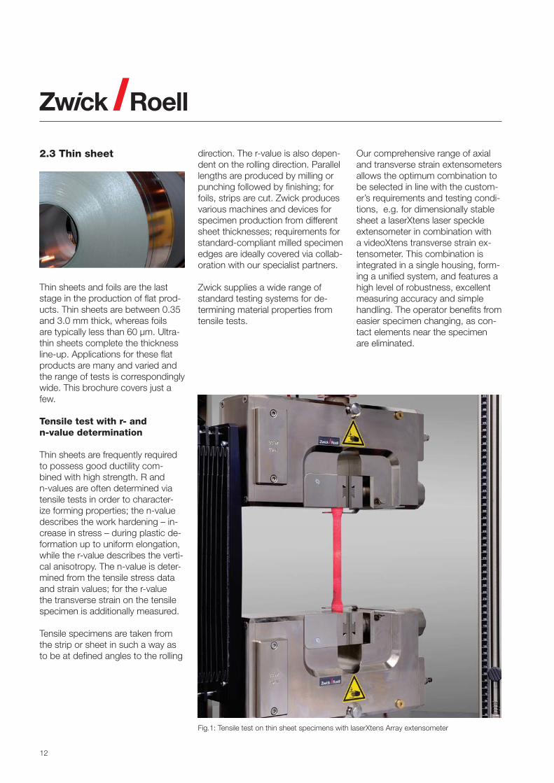
Tensile test with r- and n-value determination
Thin sheets are frequently required to possess good ductility com-bined with high strength. R and n-values are often determined via tensile tests in order to character-ize forming properties; the n-value describes the work hardening – in-crease in stress – during plastic de-formation up to uniform elongation, while the r-value describes the verti-cal anisotropy. The n-value is deter-mined from the tensile stress data and strain values; for the r-value the transverse strain on the tensile specimen is additionally measured.
Tensile specimens are taken from the strip or sheet in such a way as to be at defined angles to the rolling
direction. The r-value is also depen-dent on the rolling direction. Parallel lengths are produced by milling or punching followed by finishing; for foils, strips are cut. Zwick produces various machines and devices for specimen production from different sheet thicknesses; requirements for standard-compliant milled specimen edges are ideally covered via collab-oration with our specialist partners.
Zwick supplies a wide range of standard testing systems for de-termining material properties from tensile tests.
Our comprehensive range of axial and transverse strain extensometers allows the optimum combination to be selected in line with the custom-er’s requirements and testing condi-tions, e.g. for dimensionally stable sheet a laserXtens laser speckle extensometer in combination with a videoXtens transverse strain ex-tensometer. This combination is integrated in a single housing, form-ing a unified system, and features a high level of robustness, excellent measuring accuracy and simple handling. The operator benefits from easier specimen changing, as con-tact elements near the specimen are eliminated.
Fig.1: Tensile test on thin sheet specimens with laserXtens Array extensometer

13
Zw
ick
Ro
ell G
roup
Ap
plic
atio
nsP
rod
ucts
Ductility tests
Good ductility properties are in great demand for thin sheet. Typical forming procedures such as deep drawing and stretch forming are reproduced via standardized test methods, for which Zwick supplies Type BUP sheet metal testing ma-chines, with drawing forces up to 1,000 kN
An important but complex test is the determination of the forming limit curve, from which design-ers can derive limit strains which should not be exceeded during forming processes. The optical measurement technology required for recording strains during the drawing process is produced in col-laboration with highly specialized concerns.
Fig.1: Cupping tool for Erichsen test Fig.4: Specimen from FLC test (Nakajima)Fig.3: Test result following Erichsen test
Fig.2: BUP 200 sheet metal testing machine with optical measuring system

14
High-speed tensile test
Material behavior at high strain-rates is critical for applications in the au-tomobile industry. Accidents involve high material deformation speeds which it is essential to take into ac-count in automobile design. The necessary material properties are determined using high-speed tensile testing machines from Zwick's HTM series. These servo-hydraulic test-ing machines achieve 20 m/s on specimens at loads up to 160 kN.
Fig.3: Z050 materials testing machine with draw-bead tool
Fig.1: Metal specimen in HTM high-speed tensile testing machine
Draw-bead test on steel sheets
This test is designed to determine the coefficients of friction between steel sheet and cup deep draw-ing tool. The ideal lubricant for the deep drawing process can then be established, enabling cracks and creases to be avoided and opti-mizing the forming process. The draw-bead unit can be installed in a standard testing machine.
For the test a sheet-metal strip (typi-cal dimensions 300 mm x 30 mm x 2 mm) is gripped axially in the upper specimen grips and the draw-bead tool closed; the sheet-metal strip is then pulled through the draw-bead tool. This procedure can be repeated automatically, the number of repeats being varied as required.
Digital control of the draw-bead tool gripping-force guarantees reliable, reproducible measured values, while the tool die can quickly be changed to cover different testing specifications.
Additional tests for thin sheet
• flexure and compression test• hardness test• shear test/weld seam test• automated testing.
Fig.2: High-speed tensile test at high tem-perature

15
2.5 Bars and rods
Zw
ick
Ro
ell G
roup
Ap
plic
atio
nsP
rod
ucts
Bars and rods are long round or square products with cross-sec-tions up to 240 x 320 mm2 and a wide variety of uses in rolling and forging: for use as base product for wire rod and sections or for trans-port industry forgings such as con-necting rods, crankshafts and steel rails; generator and turbine shafts in energy technology; as end products in bridge-building and shipbuilding or in equipment manufacturing and storage tank construction.
The demands on their mechani-cal characteristics are as varied as their applications: from high tensile for structural materials to ductile for subsequent forming processes
Tensile test
Specimens are taken from the product and prepared for the tensile test in accordance with the product shape or as specified in the product standards. Sections of products can be used directly as specimens for testing if the cross-section of the product permits; the required forces can quickly exceed 2,500 kN, with customized Zwick systems up to 5,000 kN already operating success-fully. This places particular demands on specimen grips and clamping, which Zwick meets by developing both new specimen grips and tech-niques to ensure that specimens do not fail early due to the effects of clamping.
Fig.1: laserXtens extensometer with videoXtens option for transverse strain
Fig.2: Jominy test on single specimen
Hardness test
The methods used includemicro Vickers for characteriza-tion of micro-structures, Rockwell tests and high-load Brinell test HBW10/3000. Because the hard-ness test is simple and reliable it is frequently performed and correlated with other characteristics. With long products the hardenability of the material is often determined by es-tablishing the hardness distribution along a rod following a tempering and quenching test (Jominy test). Zwick’s product range contains testing machines for all required hardness testing methods and in-cludes automated Jominy testers.

16
Fig.1: Fatigue test on round specimen
Fatigue test
The uses to which products are put in transport and energy tech-nology place particular demands on the safety of the products and of components made from them. The material properties for fatigue strength and fatigue limit which are determined in fatigue tests frequent-ly have a safety-relevant impact on the choice of material and design of parts. Specimens are tested under cyclic load conditions and under al-ternating tension-compression load-ing. Zwick can supply fatigue testing machines with electromagnetic drive up to 1,000 kN as standard. The largest servo-hydraulic testing machine currently in use can handle loads up to 5,000 kN.
• robust servo-hydraulic systems, proven in service
• robust units with electromagnetic resonance drive
• specimen clamping for all relevant tests
• control and evaluation technology developed and built/programmed at Zwick.
Fig.2: Torsion test device for Vibrophore
Fatigue under torsional oscil-lation
The behavior of products under tor-sion can be of interest. For static testing Zwick supplies drives which when used in combination with materials testing machines can apply torque to the specimen and determine the corresponding mate-rial properties. It is also possible to superimpose multiple load axes and test the material in accordance with its use.
For fatigue testing under high torque alternating load, frequencies up to over 60 Hz can be achieved in a Vi-brophore (HFP) equipped with spe-cial test fixtures. Using resonance
conditions means that the test is both quick and, due to low power consumption, cost-effective.
• customized fixtures/devices built and supplied
• quick testing• high energy efficiency• very low maintenance require-
ments
Additional tests for rods and bars
• tensile test at elevated temperature• creep test• flexure and compression tests• rotating bar bending fatigue test• Charpy impact test• fracture mechanics test

17
2.6 Sections/profiles and reinforcing steel
Tensile test
Because concrete has high com-pressive strength but lower tensile strength, it is reinforced by embed-ding steel in it. Reinforcing steels are mainly produced in diameters from approx. 5 mm to approx. 60 mm.
The smaller diameters are then fur-ther processed into mats or lattices before having concrete poured over them on site.
Zwick supplies hydraulic testing ma-chines and flexure test kits as per standards.
If required two test areas can be installed on electro-mechanical test-ing machines and used for flexure and tensile tests, eliminating the need to modify the test arrange-ment.
• plug-in system for easy attach-ment of flexure test kit
• standard-compliant flexure test kits
• use of two test areas in one test-ing machine
• optional side working area
Testing these ribbed steels poses a particular challenge because, apart from cutting to length, no further mechanical specimen preparation takes place. The on-specimen strain measurement required for precise determination of the yield point is mainly carried out with the Makro extensometer, which records the strain up to break reliably with no detrimental effects to itself. The precision offered by today's optical extensometers is fully equal to that of mechanical types.
Flexure test
Flexure tests on reinforcing steel are used to test ductility. The speci-men must not lose strength and no cracks must be detected on visual inspection. Various die radii and an-vils are specified, depending on the standard, the bending angle as a rule being 90° or 180°. For this test
Zw
ick
Ro
ell G
roup
Ap
plic
atio
nsP
rod
ucts
Sections and profiles in various materials are rolled or drawn out of semi-finished products such as billets or bars; in many cases they are also welded from bar material. They are used in a vast number of applications, requiring a wide variety of mechanical tests. Together with the reinforcing steel and ribbed re-inforcement bars (rebars) so vital to civil engineering they form a group of important structural materials which – in the case of concrete-reinforcing steel – are subject to regulatory control.
Fig.1: Tensile test on steel rebar with mak-roXtens extensometer
Fig.2: Flexure test kit for steel rebarinstalled in specimen grips for tensile tests

18
Tensile shear test
The weld points of reinforcing mats and lattices are tested for shearing. This involves removing specimens from welded mats and lattices and placing them in special close-fitting specimen grips. Specimen grips used for this type of test must be accurately matched to the diameter and position of the ribbed wires in order not to influence the shearing forces. Zwick has many decades of experience in this area and has de-veloped a comprehensive range of accessories.
Automation of reinforcement steel testing
Reinforcing steel is produced in large amounts and must be con-tinually tested for production moni-toring. Zwick has developed auto-mated systems in which specimens cut to length from rod material or separated from mats and lattices are loaded manually into magazines, after which they are tested com-pletely automatically. Artificial aging at 100°C can also be integrated into this type of testing system. Cross-sections are measured with high
Fig.1: Welded seam test on T-joint
Fig.2: Shear test on truss
Fig.3: Detail of test fixture
Fig.4: Robotic testing system for testing reinforcing steel
Fig.5: Automatic length measurement Fig.6: Automatic rib measurement
accuracy and in accordance with standards and specimens can op-tionally be sorted according to test result for later visual inspection.
• customized total solutions• integration of all relevant tests• high availability• useful options for forwarding fault
reports

19
Zw
ick
Ro
ell G
roup
Ap
plic
atio
nsP
rod
ucts
Cyclic test
Earthquake protection requirements for high-rise structures mean that reinforcing steels for certain coun-tries must be subjected to specific tests. Standard-compliant cyclic tensile-compression tests (carried out on ribbed steel rods cut into lengths) depart significantly from the elastic range of the specimen. Grip-to-grip separation, stroke and frequency are specified by the stan-dard according to the specimen di-ameter. After the test the deformed specimen is examined visually for cracks.
The power and short-term energy needed for these tests is consider-able. Zwick has developed a servo-hydraulic testing machine with hydraulic accumulator for this test, enabling loads of over 1,200 kN to be applied with strokes of more than 20 mm at over 1 Hz.
• earthquake tests as per standard• hydraulic, parallel-closing speci-
men grips for compression and tensile loading
Fatigue test
Reinforcing steels are required by standard to have a defined fatigue strength, which must be verified. These fatigue tests are most quickly and economically performed using Vibrophores (resonance pulsators). The Zwick Vibrophore offers an op-timum solution for this application up to 1,000 kN. Specimens can be up to 36 mm in diameter; from 14 mm they must be grouted - a grout-ing device is available.
Fig.1: High-capacity testing machine for earthquake testing as per standard
Fig.2: Specimen grips and specimen grout-ing for rebars

20
2.7 Wire and cable
All metals can be formed into wire, which is a very common metal product form.
Wires are used in all areas of the manufacturing industry: in construc-tion engineering, in electrical tech-nology and energy technology, in aircraft and automobile manufacture and in medical technology.
Wire braided into cables is used in load-bearing applications in cable-ways, lifts and cranes, in bridge-building, anchorings and fastenings.
The wide range of applications places extremely varied mechani-cal demands, with the result that testing material properties is often highly safety-relevant.
Tensile test on wire
Tensile tests on wire represent a challenge for specimen grip design. Wires can be very thin and at the same time very strong; as they can-not be machined for testing, cut-off lengths are used and require suit-able gripping arrangements - simply clamping wires between jaws can cause failure at an unwanted loca-tion. Zwick can supply specimen grips featuring various gripping technologies for safe, reliable test-ing. For strain measurement the vi-deoXtens optical extensometer can be used with thin wires; with thicker wires optical or contact-type exten-someters can be employed.
• wide range of specimen grips for single wires
• the right extensometer for every application.
Fig.1: Tensile test on fine wire with makroXtens extensometer Fig.2: Clamping device for steel strand
Tensile test on steel strand
In steel strand several wires are wound with each other; under tensile loading they try to unwind. Zwick’s special clamping technol-ogy avoids premature failure at an unwanted location. Failure of steel strand generally involves individual wires whipping about, with a strong probability of damage to contact-type extensometers; we therefore recommend using our optical exten-someters, which feature measure-ment travel of 900 mm and high resolution (1.5 μm over the entire measurement travel).

21
Tensile test on wire ropes and cables
High strain levels have to be taken into account during tensile tests on wire ropes as do high forces, both resulting in torn individual wires whipping back with high energy on failure. Safety precautions must be taken to eliminate risks from the test.
Rotating bar bending fatigue test
In many applications, wires are sub-jected to various cyclic stresses. Fatigue strength can be determined quickly and easily in rotating bar bending fatigue tests, in which the rapidly rotating (up to 6,000 rpm) specimen is additionally loaded with a force perpendicular to the axis of rotation. This flexure plus the rota-tion provides a tensile-compression loading of the specimen. Specimen preparation is especially important here, an undamaged surface being essential. Fig.1: Servo-hydraulic horizontal testing machine for cyclic tests on wire ropes
Fig.2: Rotating bar bending testing machine (UBM)
Additional tests for wire and cable
• torsion test• hardness test• fatigue test
Zw
ick
Ro
ell G
roup
Ap
plic
atio
nsP
rod
ucts

22
2.8 Pipes
Pipes transport granulated materi-als, liquids and gases; these can be aggressive or neutral.
Pipes are used in widely differing environments, including nuclear power stations, in and above the ground for transporting oil and natural gas, in engines for fuel de-livery and exhaust gases and in the chemical industry.
This causes them to be manufac-tured from a wide range of materials and alloys, using various production processes, in an apparently endless variety of forms.
Fig.2: High-capacity testing machine with double-actuator hydraulic grips
Tensile test
Ways of testing tensile specimens taken from or consisting of pipes vary according to the product form. Thin pipes are squashed at the ends for a sufficient length and then pulled, while cores are used in larger diameter pipes to prevent pre-damage through crushing With larger pipes standardized speci-mens are produced from mate-rial removed from the wall of the pipe. It is possible that specimens (taken longitudinally) may display the curve of the pipe radius; for reli-able, pre-damage-free testing this radius should be compensated for with suitably shaped counterpieces. Zwick supplies tensile testing ma-chines from 500 N to 2,500 kN, with appropriate specimen grips.
Fig.3: Tensile test on pipe-wall specimen
Fig.1: Pipe-wall specimen
23
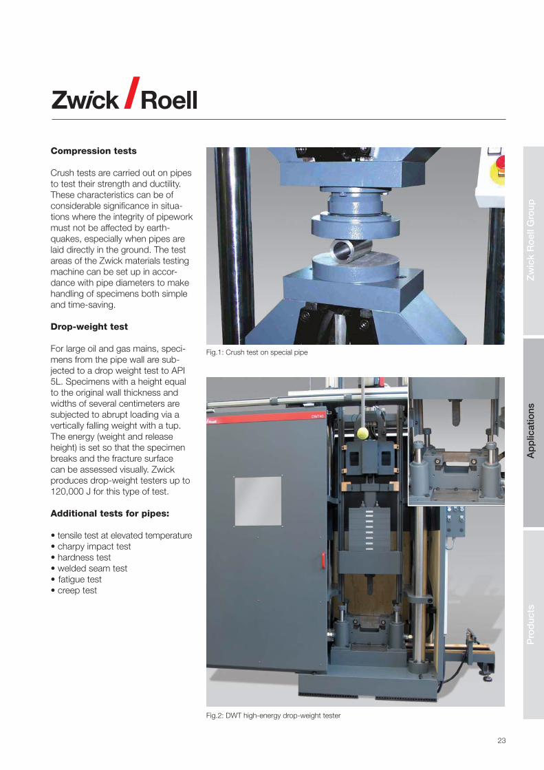
Fig.1: Crush test on special pipe
Fig.2: DWT high-energy drop-weight tester
Compression tests
Crush tests are carried out on pipes to test their strength and ductility. These characteristics can be of considerable significance in situa-tions where the integrity of pipework must not be affected by earth-quakes, especially when pipes are laid directly in the ground. The test areas of the Zwick materials testing machine can be set up in accor-dance with pipe diameters to make handling of specimens both simple and time-saving.
Drop-weight test
For large oil and gas mains, speci-mens from the pipe wall are sub-jected to a drop weight test to API 5L. Specimens with a height equal to the original wall thickness and widths of several centimeters are subjected to abrupt loading via a vertically falling weight with a tup. The energy (weight and release height) is set so that the specimen breaks and the fracture surface can be assessed visually. Zwick produces drop-weight testers up to 120,000 J for this type of test.
Additional tests for pipes:
• tensile test at elevated temperature• charpy impact test• hardness test• welded seam test• fatigue test• creep test
Zw
ick
Ro
ell G
roup
Ap
plic
atio
nsP
rod
ucts

24
2.9 Castings and forgings
Castings and forgings are predomi-nantly used in the automotive indus-try and for aircraft manufacture, as well as for power-station construc-tion. Casting technology allows complex parts to be manufactured cost-effectively, with an ever-increasing use of light metal cast-ings to reduce weight, especially in engine manufacture. Forged com-ponents are used to meet severe demands on strength, or extremes of pressure and impact loading, as with crankshafts and connecting rods in engines, or generator and turbine shafts in power stations.
Fatigue test
Where castings and forgings are concerned, reliable estimation of durability is of particular importance in practice. This requires specimens and, importantly, entire components such as forged connecting-rods to be tested intensively under cyclic loadings. Operating conditions are reproduced in Vibrophores and components stressed with cyclic loads up to 1,000 kN at frequen-cies up to 285 Hz. Zwick’s range of highly efficient, cost-effective Vibro-phores is now backed by a greatly expanded servo-hydraulic testing machine range.
Fig.1: Tensile test on round specimen
Fig.2: Fatigue test on connecting rod
Tensile test
Cast and forged components are produced so as to require the mini-mum of further processing to make them fit for their intended purpose. For tensile tests this means either removing specimens from specified locations or using the component as a whole to determine tensile strength. Testing the whole com-ponent requires high test loads and component-specific gripping ar-rangements and fastenings, while component geometries often result in the production of specimens with small final dimensions. For small
Fig.3: Rockwell test on hot-extruded engine valves
round specimens Zwick provides special specimen grips which are easy to handle and allow the use of automatic extensometers; complete components are catered for by a comprehensive accessory and op-tion package.
Hardness test
The hardness value is an important characteristic when monitoring the manufacturing process for cast and forged components. The high-load Brinell method is often used on components, the large indentations enabling a stable average value for the metallographic constituents to be obtained.
The hardness of metallographic constituents is determined on me-tallographic specimens via Vickers micro-hardness testing. Zwick’s operator-friendly Brinell hardness testing machines with automatic indentation measurement up to load level 250 kg are complemented by a comprehensive range of micro Vick-ers instruments, from manual to fully automatic.
Additional tests for cast and forged components:• tensile test at elevated tempera-
ture• creep test• torsion test• rotating bar bending fatigue test• charpy impact test

25
2.10 Fasteners
First and foremost amongst fasten-ers are nuts and bolts in all their many variations; screws, rivets and hooks and eyes are also used to join parts which must not separate under load. Fastener technology in general, particularly welding and as-sociated technologies, will also be considered here.
Tensile test
Bolts and screws are selected very carefully with regard to their in-dustrial application and integrated precisely into the design. Accurate determination (via tensile tests) of the elastic tensile modulus and the limits of elastic loading is essen-tial, as it is from these that the limit forces for a secure, reliable screwed fastening are established.
Zwick’s comprehensive selection of specimen grips, with the option of customized solutions, simplifies testing in this area.
Fig.1: Shear test on riveted joint
Fig.2: Tensile test on threaded fasteners
Shear test
In addition to single-axis tensile loading, shear loads also occur in fasteners in service and can quickly cause a joint to part.
Shear tests on joined parts or specimens are therefore essential, particularly where riveted joints are involved. Accurate load application is essential to prevent other forces arising in addition to the shear force and distorting results.
Zwick works with the customer to develop a specification for the cor-rect gripping of the specimen or component and then produces the required arrangement.
These test devices can be simple or very complex, but always do exactly what is required of them.
Zw
ick
Ro
ell G
roup
Ap
plic
atio
nsP
rod
ucts
26
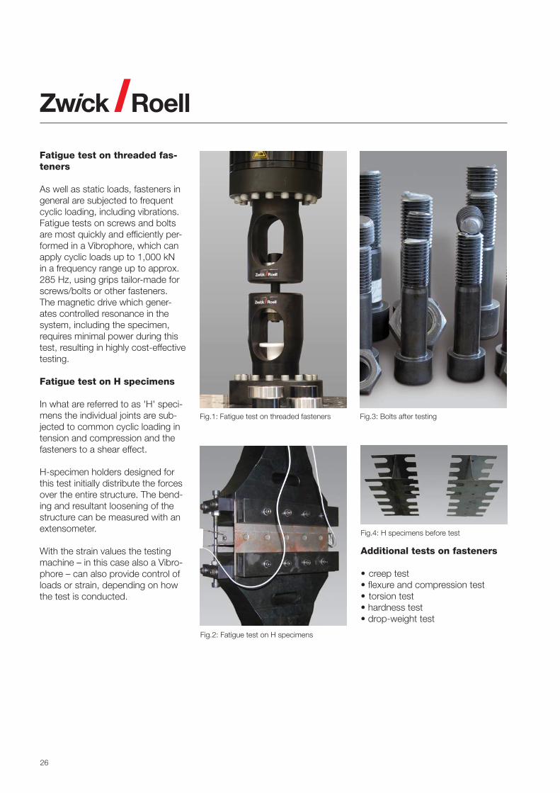
Fatigue test on threaded fas-teners
As well as static loads, fasteners in general are subjected to frequent cyclic loading, including vibrations. Fatigue tests on screws and bolts are most quickly and efficiently per-formed in a Vibrophore, which can apply cyclic loads up to 1,000 kN in a frequency range up to approx. 285 Hz, using grips tailor-made for screws/bolts or other fasteners. The magnetic drive which gener-ates controlled resonance in the system, including the specimen, requires minimal power during this test, resulting in highly cost-effective testing.
Fatigue test on H specimens
In what are referred to as 'H' speci-mens the individual joints are sub-jected to common cyclic loading in tension and compression and the fasteners to a shear effect.
H-specimen holders designed for this test initially distribute the forces over the entire structure. The bend-ing and resultant loosening of the structure can be measured with an extensometer.
With the strain values the testing machine – in this case also a Vibro-phore – can also provide control of loads or strain, depending on how the test is conducted.
Fig.3: Bolts after testingFig.1: Fatigue test on threaded fasteners
Fig.2: Fatigue test on H specimens
Fig.4: H specimens before test
Additional tests on fasteners
• creep test• flexure and compression test• torsion test• hardness test• drop-weight test
27
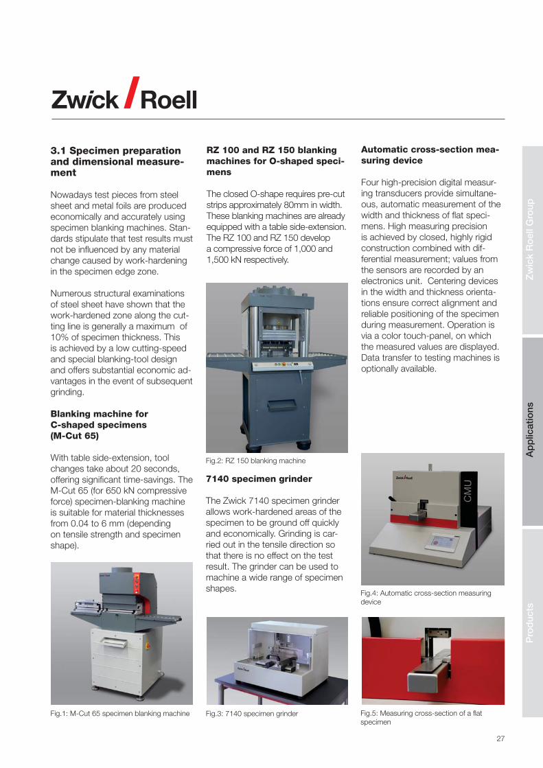
3.1 Specimen preparation and dimensional measure-ment
Nowadays test pieces from steel sheet and metal foils are produced economically and accurately using specimen blanking machines. Stan-dards stipulate that test results must not be influenced by any material change caused by work-hardening in the specimen edge zone.
Numerous structural examinations of steel sheet have shown that the work-hardened zone along the cut-ting line is generally a maximum of 10% of specimen thickness. This is achieved by a low cutting-speed and special blanking-tool design and offers substantial economic ad-vantages in the event of subsequent grinding.
Blanking machine for C-shaped specimens (M-Cut 65)
With table side-extension, tool changes take about 20 seconds, offering significant time-savings. The M-Cut 65 (for 650 kN compressive force) specimen-blanking machine is suitable for material thicknesses from 0.04 to 6 mm (depending on tensile strength and specimen shape).
Fig.1: M-Cut 65 specimen blanking machine
RZ 100 and RZ 150 blanking machines for O-shaped speci-mens
The closed O-shape requires pre-cut strips approximately 80mm in width. These blanking machines are already equipped with a table side-extension. The RZ 100 and RZ 150 develop a compressive force of 1,000 and 1,500 kN respectively.
7140 specimen grinder
The Zwick 7140 specimen grinder allows work-hardened areas of the specimen to be ground off quickly and economically. Grinding is car-ried out in the tensile direction so that there is no effect on the test result. The grinder can be used to machine a wide range of specimen shapes.
Fig.2: RZ 150 blanking machine
Fig.3: 7140 specimen grinder
Automatic cross-section mea-suring device
Four high-precision digital measur-ing transducers provide simultane-ous, automatic measurement of the width and thickness of flat speci-mens. High measuring precision is achieved by closed, highly rigid construction combined with dif-ferential measurement; values from the sensors are recorded by an electronics unit. Centering devices in the width and thickness orienta-tions ensure correct alignment and reliable positioning of the specimen during measurement. Operation is via a color touch-panel, on which the measured values are displayed. Data transfer to testing machines is optionally available.
Zw
ick
Ro
ell G
roup
Ap
plic
atio
nsP
rod
ucts
Fig.4: Automatic cross-section measuring device
Fig.5: Measuring cross-section of a flat specimen

28
3.2 Electromechanical test-ing machines
zwickiLine - small footprint, big range of application
These high-quality, easy-to-operate single-column materials testing ma-chines were specially designed for tensile and compressive test loads up to 5 kN.
Shorter versions are used for flexure tests or function tests, while long load-frames are ideal for tensile tests, for example on wire and strip.
ProLine - the machine range for standard tests
Do you carry out goods-inwards tests or quality assurance to estab-lished standards? Do you need to measure force and deformation, or strain? Then ProLine is just the ma-chine for you. The load frames are equipped with guide columns and drive-screws and are available for nominal loads from 5 kN to 100 kN. A wide range of specimen grips, test fixtures and mechanical and optical extensometers is also avail-able.
AllroundLine - extra-conve-nient, for more complex test-ing situations
The AllroundLine table-top models feature two patented extruded-section columns which are light, flexurally stiff and function as both lead-screw guides and guards. The table-top versions of AllroundLine can be provided with stands to en-able the test area to be located at the optimum height for the operator or the application. The floor-stand-ing versions are equipped with two or four guide-columns. Extremely

29
stiff load frame construction ensures optimum conditions for accurate alignment of test axes. The load frames can be provided with one or two test areas, while the lower crosshead can be in the form of a mounting plate for component tests. For torsion tests the load frame is equipped with a torsion drive with testControl II control and appropriate sensors.
testControl II - the measure-ment and control electronics
testControl II is 'Made by Zwick'and is ideally aligned to the de-mands of metals testing. Mea-sured values from the sensors are sampled at a very high rate and processed in testXpert II at an ac-quisition rate of up to 2,000 Hz. Add to this 24-bit signal resolution
and the result is extremely high test-result accuracy and reproducibility over the entire speed range. The innovative testControl II electron-ics set the benchmark with regard to safety technology, performance, quality, control and drive technology.
29
Zw
ick
Ro
ell G
roup
Ap
plic
atio
nsP
rod
ucts

30
High-capacity testing ma-chines
Series-produced Zwick Roell high-capacity testing machines start from 330 kN capacity and range up to 2,500 kN. Customized spe-cial solutions up to over 5,000 kN are also available. In high-capacity testing machines the test force is generated by hydraulic actua-tors. Developments in lead-screw technology mean that high-capac-ity testing machines can now be
equipped with electromechanical drives of up to 2,000 kN capacity. As well as being more convenient in everyday use, electromechanical drives are more precise and require very little maintenance.
In addition to the standard H (for hy-draulic) and E (electro-mechanical) series, there is also a standard SP (special) series which can be used for routine standard applications in the metals field from 400 kN to 2,000 kN. Derived from the SP se-
ries, the SP-T standard series is an extremely compact high-capacity machine for the 400 kN to 1,200 kN range.
All high-capacity testing machines are extremely stiff and robust and offer a high level of reliability.
Fig.1: Available from Zwick as standard - high-capacity testing machines up to 2,500 kN

31
3.3 Hardness testing ma-chines and instruments
Zwick Roell offers wide-ranging and innovative hardness testing solu-tions.
Our hardness testing machines and instruments are based on our many years of experience supplying a wide range of equipment around the world and maintaining commu-nication with the people who use it. The versatility and high 'intelligence' of our testing systems is achieved with up-to-date mechanical com-ponents, powerful electronics and user-oriented software.
The Zwick Roell Group has EN ISO/IEC 17025-accredited calibration laboratories, guaranteeing traceable certification of Zwick Roell hardness testers, hardness reference blocks and indenters.
ZHU/zwickiLine universal hardness testing machine
Based on zwickLine, the ZHU/Z2.5 universal hardness testing machine can be used for the classical hard-ness testing methods of Rockwell, Vickers, Knoop, Brinell and ball indentation hardness.It is also suit-able for the innovative instrumented indentation test used to determine Martens hardness up to 2,500 N plus additional metallic materials pa-rameters to EN ISO 14577.
The ZHU/Z2.5 features a patented hardness measuring head with integrated digital depth and force measuring system, mounted in a modified zwicki-Line materials test-ing machine. Add to this state-of-the-art testControl measurement and control electronics and Zwick’s intelligent testXpert testing software and the result is a well-balanced, high-precision measuring system. Fig.2: ZHU/zwickiLine universal hardness
testing machine
Fig.1: Zwick has a comprehensive range of hardness testing machines for a variety of test methods
Zw
ick
Ro
ell G
roup
Ap
plic
atio
nsP
rod
ucts

32
ZHV30/zwickiLine Vickers hardness testing machine
The ZHV30/zwickiLine Vickers hard-ness testing machine covers hard-ness tests to ISO 6507 and ASTM E 384 and Brinell hardness tests to ISO 6506 in a test load range from 0.1 kgf to 31.25 kgf.
The ZHV30/zwickiLine is a com-bination of a zwickiLine hardness testing machine, an accessory unit for optical hardness testing and tes-tXpert testing software. The system is designed as a top-loader, where-by the specimen rests firmly on the support table while the hardness testing unit is lowered automatically onto the specimen surface. This en-ables maximum flexibility with speci-mens of different height.
Fig.1: ZHV30/zwickiLine universal hardness testing machine
ZHVμ micro-Vickers hardness tester
The ZHVμ Micro Vickers hardness tester covers Vickers and Knoop hardness tests to EN ISO 6507, EN ISO 4545 and ASTM E384 in the test-load range from 0.01 kgf to 2 kgf. The hardness tester is equipped with an automatic 6-po-sition turret for up to 2 indenters
Fig.2: HD software with Vickers indentation and images of embedded specimens
and up to 4 lenses This enables test methods to be changed and selected via menu buttons without changing the indenter or a lens. For more sophisticated or for auto-mated applications, PC controlled versions are available as semi or fully automatic systems based on the High Definition Software (HD). One particular use for these is for automated multiple traverse tests.
ZHR Rockwell hardness tes-ters
The various instruments in this product range are designed for:• classical Rockwell methods (force level 60-150 kgf)• superficial Rockwell method (force levels 15 - 45 kgf) • combination of these methods (force levels 15 - 150 kgf)
A special feature of these instru-ments is a patented indenter- holder for hardness testing at difficult-to-access locations. Straightforward operating thanks to:• automatic operation• load-weight selection via control knob or touch screen
• automatic load application and removal• automatic evaluation, including conversion as per standard
Fig.3: ZHR 4150 LK Rockwell hardness tester

33
ZHU250CL universal hardness tester
The ZHU250CL hardness tester employs the latest technology, with state-of-the-art closed-loop control for precise test-load application. Accuracy exceeds the requirements of all relevant ISO and ASTM stan-dards.
The unique '4-plus-4' fixture car-ousel for up to four lenses and four indenters (at the same time) with its special vertical layout enables testing in difficult-to-access loca-tions. Operation and control of the ZHU250CL is via high-definition software.
Fig.1: ZHU250CL universal hardness tester
Nanomechanical hardness tester
The ZHN Universal Nanomechani-cal Tester provides the force and displacement resolution necessary for comprehensive mechanical characterization of thin films and coatings or small surface areas, in-cluding measurement of indentation hardness, indentation modulus and Martens hardness to EN ISO 14577 (instrumented indentation test).
The hardness tester can be equipped with a second, inde-pendent measuring head for the lateral direction (Lateral Force Unit). The two measuring heads can then be combined, giving a greatly increased range of measur-ing options. Additional uses for the machine then include micro scratch tester, micro wear tester, fatigue tester and high-resolution profilom-eter.
Portable hardness testers Portable hardness testing is used for large or non-transportable com-ponents and plant.
The RH-150 hardness tester com-bines typical Rockwell or superficial Rockwell test methods with new, high-precision displacement and force sensor technologies. This versatile instrument allows trouble-free determination of direct, precise hardness values in the relevant Rockwell scales at any desired loca-tion. Conversion as per standard is also possible.
The portable HT1000/2000 makes light work of testing large, heavy forgings and castings such as steel-works rollers, turbine housings etc.
Fig.2: Scratch test and Berkovich indenta-
tions
Fig.3: HT1000/2000 rebound hardness tester
Fig.4: RH-150 hardness tester
Zw
ick
Ro
ell G
roup
Ap
plic
atio
nsP
rod
ucts

34
Application
It is common practice to install the high-temperature unit directly in the materials testing machine. This arrangement allows tensile tests to be performed at both room tem-perature (ISO 6892-1) and elevated temperature (ISO 6892-2). During testing at room temperature, com-ponents such as the high-tempera-ture furnace and high-temperature extensometer are simply swung out of the test area. Using a centrally divided hinged furnace enables the pull-rods in use to be inserted and withdrawn easily via a quick-change system.
3.4.Tests at high tempera-ture
The high-temperature system itself consists of three main components:
• the swivel-mounted high-temper-ature furnace with high-tempera-ture controller;
• the high-temperature extensom-eter (standardized: contact-type systems; customized: non-contact systems), which can also simply be swung out of the test area; suitable access (port) is re-quired in the furnace;
• the load string, consisting of con-nectors for the quick-change system on the testing machine, the pull-rods, via which the tensile force is transmitted into the fur-nace and the specimen adapters at the end of the pull-rods.
In practice, the most common specimens are threaded-end specimens (e.g. as described in DIN 50125). Flat specimens taken from thin sheets are held in positive-fit flat-specimen grips. Standardized specimen adapters for these speci-mens are available in various materi-als for temperatures up to 1,200°C. Systems are similarly available for compression and flexure tests up to 1,600°C.
The combination of the volumes in the furnace, the temperature toler-ances and dwell times specified in the standard, together with the heating and cooling times, mean that the duration of tests is more or less fixed. To reduce specimen throughput time, systems with mul-tiple furnaces are available from our range.
Fig.1: High-temperature furnace with laserXtens
Fig.2: High-temperature furnace with HT extensometer
Fig.3: Induction heating with laserXtens
Fig.4: High-temperature tests in vacuum furnace
Fig.5: Carousel with 3 high-temperature furnaces
Fig.6: Servo-hydraulic testing machine with high-temperature furnace

35
3.5 Creep testing machines
The design and operation of high-temperature components require material properties which have been proven over an extended period. Creep testing represents one of the most important experiments for describing the high-temperature be-havior of materials (standardized in ASTM E139, ISO 204 and others).
For short-term creep tests with loading times up to 10,000 hours, screw-drive creep testing machines are often used. These may be of single or double-screw design.This type of drive allows both creep tests (constant load and temperature) and stress relaxation tests (constant strain or strain rates (SSRT) and temperature) to be performed. For long-term tests > 10,000 hours, lever-arm machines are mainly used (spring loading or
deadweights). As with electrome-chanical machines, spring-loaded machines are suitable for force, stress and strain control.
KAPPA SS / DS electrome-chanical creep testing ma-chines
The Kappa SS / DS creep testing machines are suitable for creep tests and advanced creep tests re-quiring maximum control precision.
KAPPA SS - CF electrome-chanical creep testing ma-chine
The Kappa SS - CF creep testing machine is equipped with a cen-tral lead-screw and is suitable for creep tests and strain-controlled creep fatigue (CF) tests requiring maximum precision in strain control. The machine features backlash-free
drive, an important criterion for tests under alternating tensile/compres-sion loading. Together with either contact-type extensometers or the non-contact videoXtens HT/TZ extensometer, maximum flexibility and outstanding control character-istics are combined in an innovative testing machine.
Fig.1: KAPPA DS (left) and KAPPA SS - CF (right) electromechanical creep testing machines
Fig.2: Crack expansion and crack progress measurement as per ASTM E 1457
Fig.3: Testing for hydrogen embrittlement as per ASTM F519
Fig.4: Gaged specimen for creep tensile test (extensometer and thermocouples)
Zw
ick
Ro
ell G
roup
Ap
plic
atio
nsP
rod
ucts

36
3.6 Fatigue testing ma-chines
Load frames from the HA and HB ranges form the classical servo-hydraulic testing machine. They are used to determine material properties under cyclic loading; these include fatigue limit (S-N test), low-cycle fatigue (LCF), fracture mechanics etc.
The HC frame is designed as a table-top model for forces up to 25 kN and features an integrated hard-chromed T-slotted platform. This enables testing in corrosive media such as saline solutions.
Fig.1: HA and HB series servo-hydraulic testing machines; Vibrophore
The load frames feature 2-column design for materials testing under oscillating load in a closed force-flow. The frame is supported on vibration-isolating leveling units The efficiency of the testing system is enhanced by the especially high axial and lateral stiffness of the load frames, which are therefore also suitable for combined tensile, compression and torsion loads. The frames also feature extremely pre-cise alignment; following installation of the testing actuator and load cell, alignment accuracy is 0.1 mm per meter separation; at distances be-low 350 mm the offset is constant at 0.05 mm. All fixtures are flange-
mounted with a centering spigot, eliminating the need for retrospec-tive alignment of the load string.
Vibrophores represent a cost-effective alternative to other types of testing machine for fatigue tests on materials or components in which only sinusoidal loading sequences with constant or variable amplitude and mean load are applied. They are primarily used to determine material and component fatigue-strength in the areas of fatigue life and fatigue limit.

37
3.7 Sheet metal testing machines
Range of application
Testing the ductility of sheet met-als in accordance with established standards.
Investigating the influence of surface treatments and lubricants in typical forming techniques including cup-ping and earing tests. Checking the effect of tool and process param-eters on the forming process.
Determining the forming limit curve (FLC) using optical measuring sys-tems by partners of the Zwick Roell Group.
Special features
• fast, easy equipment change (e.g. drawing punches, blank holders etc.); numerous modular upgrad-ing options available
• low actuator-piston friction en-ables accurate measurement recording and excellent reproduc-ibility.
• hydraulic cup-extractor via inte-grated piston, with piston rod act-ing through drawing punch (BUP 200 upwards)
• swiveling electronic display unit adjustable to convenient viewing position; all controls arranged er-gonomically
• adjustable automatic blank-holder load-removal during test enables cup-drawing without crushing of ears (BUP 200 upwards)
• automatic setting of pre-selected sheet clamping force after blank-ing procedure
• automatic piston withdrawal and switch-off after end of test via crack recognition or on reaching maximum ram stroke (s-limit)
• alteration of deep drawing speed during test possible (BUP 400 upwards)
• hydraulic opening and closing of tool head
• extremely quiet, clean operation.
Fig.1: BUP sheet metal testing machines from 100 kN to 1,000 kN, optionally with optical measuring system
Zw
ick
Ro
ell G
roup
Ap
plic
atio
nsP
rod
ucts

38
3.8 Pendulum impact tes-ters
Application
Pendulum impact testers are used to determine impact energy, im-pact strength and notched impact strength of standardized metal specimens and components. The design and layout of our pendulum impact testers conform to all rel-evant standards,allowing safe, reli-able, Charpy and Izod testing, plus impact tensile tests and tests to Brugger, in compliance with interna-tional application standards.
To accommodate differing materials, specimen cross-sections and test standards, pendulums with potential energy up to 750 joules, standard-compliant specimen supports and
clamping fixtures are available; these are easy to change, with no need for time-consuming adjust-ment.
Features
• stiff, torsion-free frame with low-friction pendulum mounting (the energy goes into the specimen, not into the instrument base)
• CE-compliant safety devices pro-vide operator protection
• good access to test area• easy accessory change• optional operator-friendly testXpert
testing software.
Accessories
Temperature-conditioning devices are available in a range from -90°C to +200°C. All pendulum impact testers can be fully or partly automated.
This includes partly or fully automat-ic temperature-conditioning, feed and testing of Charpy specimens at both plus and minus temperatures as per EN 148 and ASTM E 23.
Specimen cooling is by means of a cooling unit or liquid nitrogen (cool-ing to max. -180 °C).
Heating takes place electrically, while heat transfer between speci-mens and the temperature-condi-tioning unit is conductive (solid body contact).
Fig.1: HIT 50P and RKP 450 pendulum impact testers for Charpy and Izod tests

39
3.9 Dynamic impact testing machines and drop weight testers
HTM high-speed testing ma-chines
Zwick's HTM range of servo-hy-draulic high-speed testing machines enable strain-rate-dependent char-acteristic values to be determined over a wide speed range. High-speed puncture, compression and tensile tests plus peel and shear tests can be performed, while test speed can be adjusted continuously over a wide range, from quasi-static to 20 m/s.
High-energy drop weight tes-ters for testing pipeline sec-tions
The American Petrol Institution (API) requires pipes for use in pipelines to be subjected to a drop-weight test. Standardized drop-weight testers specifically designed for this ap-
plication can apply various impact energies and speeds according to requirements. Zwick drop-weight
testers can be used for testing steel specimens to all established stan-dards.
Fig.1: High-speed testing machine Fig.2: DWT 40 high-energy drop-weight tester (drop height 5 meters)
Zw
ick
Ro
ell G
roup
Ap
plic
atio
nsP
rod
ucts

40
3.10 Robotic testing sys-tems
Automatic specimen feed and han-dling systems are primarily used where statistically reliable material characteristic values are required and a high volume of specimens must be tested round the clock. Automated systems are therefore equipped in accordance with spe-cific testing requirements.
Advantages:
• objective - test results are operator independent• optimum result reproducibility results• extended testing capacity - testing can be performed during the night shift and at weekends with no operator
roboTest L
The roboTest L robotic testing sys-tem enables automatic tensile and flexure tests on round and flat spec-imens up to approximately 1 kg. It consists of a movable basic system plus application-specific extension units. To simplify filling the maga-zine, this can be removed from the magazine table and filled directly at the operator's workplace.
roboTest I
The roboTest I robotic testing system is used for automatic tem-perature-conditioning, feeding and testing of Charpy specimens as per standard in a temperature range from -180 °C to +300 °C. The sys-tem is available in semi-automatic or fully automatic versions. and can be used with an RKP or PSW 450 J (semi-automatic) or 750 J (semi- or fully automatic) pendulum impact tester. Fig. 2: roboTest I for automated Charpy and Izod tests (including specimen cooling)
Fig. 1: roboTest L for automated tensile tests on sheet metals

41
roboTest R
The roboTest R robotic testing sys-tem allows fully automatic tensile and flexure tests to be performed and is based on a flexible 6-axis in-dustrial robot with high positioning-accuracy. roboTest R scores with its consistently modular design and construction. The various measur-ing devices, including cross-section, roughness, layer-thickness, X-ray fluorescence and hardness measur-ing instruments, are arranged in a circle around the robot. Specimen throughput is increased by having several specimens in the circuit at the same time.
roboTest P
The roboTest P robotic testing sys-tem enables fully automatic tensile testing of metals with specimen weights up to approximately 10 kg. The system consists of a 3-axis specimen-feeding systemand a swiveling gripper unit.
The advantage of this design is its great flexibility with regard toindividual measuring stations. In this way different components can be accommodated, such as testing machines, specimen magazine and cross-section measuring device. The specimen magazine can be filled away from the danger area.
Fig. 1: roboTest R for automated tensile tests on sheet metals, rods and reinforcing steel
Fig. 2: roboTest P for automated tensile tests on heavy specimens, with additional sensors and measuring devices incorporated e.g. cross-section measuring device, bottom right)
Zw
ick
Ro
ell G
roup
Ap
plic
atio
nsP
rod
ucts

42
3.11 testXpert® II – the new generation of materials testing software
With testXpert Zwick introduced a uniform operating concept for all applications - regardless of which testing system is involved.
What advantages does this of-fer? Learning how to handle the software is less time-consuming. testXpert II users benefit from more than 25,000 successful installations around the world.
testXpert II’s stand-out feature is its amazingly simple, intuitive opera-tion. Meaningful icons and a clear menu structure enable rapid orien-tation and significantly reduce the familiarization phase.
Ready-made Standard test programs
Pre-programmed, tested and ready-to-use Standard test programs are available for all tests to established standards. This simplifies the first steps and ensures that the test se-quence and results evaluationare in compliance with the standard.
Flexible Master test programs
Greater freedom in designing the test sequence, operating steps, result calculation and data logging is offered by Master Test programs Here each parameter can be set individually.
Testing
The individual data are displayed – online to the test procedure – on the monitor screen. The test can be followed live. If required an ex-actly synchronized video recording can additionally be incorporated.
Results are calculated during the test, so the test sequence can be event-controlled; for example with a change of speed following determi-nation of the tensile or compression modulus.
Evaluation of test results
As many different screen layouts as required can be compiled in testXpert II, for example with ad-ditional graphics, different displays of test curves, tables and additional statistics.
Fig.2: With over 25,000 installations worldwide, testXpert is the most successful materials test-ing software on the market
Master Test ProgramsZwick supplies Master test programs for freely configurable tensile, compression, flexure, tear-growth, adhesion, peel and cyclic tests, plus Master test programs for devices.
testXpert II Export EditortestXpert II's unique import / export interfaces allow perfect integration into your IT structure for test result processing or data export.

43
3.12 Load cells
Load cells must satisfy the highest quality requirements. The basis for this is a calibration to ISO 7500-1 or ASTM E 4. This is in the form of a factory calibration and can be re-peated following commissioning of the test equipment by our Service Department as a DAkkS, COFRAC or NAMAS calibration. This means that you can always rely on your testing machine.
But there is much more to Xforce load cells - available exclusively from Zwick – than that.
Parasitic influences such as tem-perature and transverse forces have significantly less impact on test re-sults than with other comparableload cells. Xforce load cells are also very robust and more resistant to factors such as transverse forces during compression and flexure tests.
Temperature compensation makes measuring largely independent of the actual ambient temperature.This all takes place in a very
large measurement range, withinAccuracy Class 0.5 or 1. Load cells in the Xforce HP/K range typically achieve a display deviation better
than ±1 % from as low as 0.1 % of their nominal load.
Fig.2: Every load cell undergoes a Zwick factory calibration as soon as it enters service on a testing machine
Fig.1: Load cell in use
Zw
ick
Ro
ell G
roup
Ap
plic
atio
nsP
rod
ucts
Fig. 3: Load cells from the Xforce range, showing different designs

44
3.13 Specimen grips
Fig.1: Wedge grips and wedge/wedge-screw grips
Fig.2: Hydraulic grips, hydraulic grips ('body over wedge'), short-clamping hydraulic grips
Fig.3: Pneumatic grips, dumbbell/screw/threaded-end grips, high-temperature grips
Fig.4: Heavy-duty hydraulic grips for testing applications up to 2,500 kN

45
3.14 Extensometers
makroXtens / multiXtens
Automatic mechanical extensom-eters makroXtens and multiXtens satisfy the requirements for reliable determination of the initial gradient in the stress-strain diagram In com-bination with integrated fine-strain extensometers they can also be used to determine Young's modulus from a tensile test. Changing the sen-sor arms enables different types of tests, together with measurement in temperature chambers. Tilting knife-edges prevent transmission of exces-sive forces and ensure safe, reliable operation, even with brittle specimen fractures.
videoXtens / videoXtens Array
videoXtens uses the digital image correlation (DIC) method, allowing axial and transverse strain to be determined simultaneously with great accuracy. With the Array version (integrated multi-camera variant) the measurement travel and specimen coverage are significantly extended while maintaining the existing high measurement accuracy.
laserXtens / laserXtens Array
Also use the DIC method and employ the laser speckle principle, eliminat-ing the need for specimen marking while maintaining the same level of precision. The Array version (also an integrated multi-camera variant) extends measurement travel to a maximum of 310 mm.
Manual clip-on extensometer
Digital and analog clip-on extensom-eters are available in many different versions.
Fig. 1: makroXtens and variants with optional fine-strain measurement (bottom)
Fig. 2: videoXtens Fig. 5: videoXtens Array
Fig. 3: laserXtens Array Fig. 6: laserXtens Compact for short speci-mens
Fig. 4: multiXtens with optional fine-strain and transverse-strain measurement
Zw
ick
Ro
ell G
roup
Ap
plic
atio
nsP
rod
ucts
46
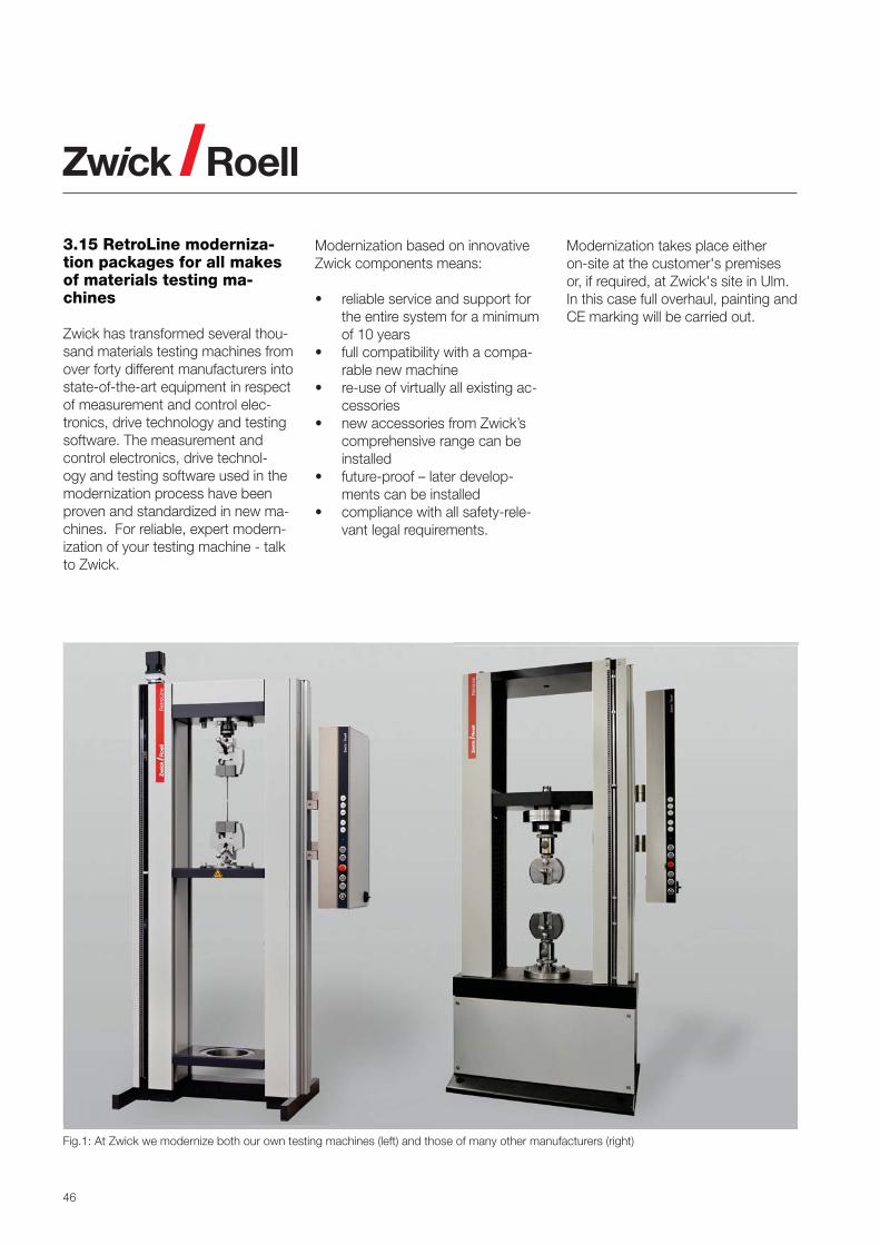
3.15 RetroLine moderniza-tion packages for all makes of materials testing ma-chines
Zwick has transformed several thou-sand materials testing machines from over forty different manufacturers into state-of-the-art equipment in respect of measurement and control elec-tronics, drive technology and testing software. The measurement and control electronics, drive technol-ogy and testing software used in the modernization process have been proven and standardized in new ma-chines. For reliable, expert modern-ization of your testing machine - talk to Zwick.
Modernization based on innovative Zwick components means:
• reliable service and support for the entire system for a minimum of 10 years
• full compatibility with a compa-rable new machine
• re-use of virtually all existing ac-cessories
• new accessories from Zwick’s comprehensive range can be installed
• future-proof – later develop-ments can be installed
• compliance with all safety-rele-vant legal requirements.
Modernization takes place either on-site at the customer's premises or, if required, at Zwick's site in Ulm. In this case full overhaul, painting and CE marking will be carried out.
Fig.1: At Zwick we modernize both our own testing machines (left) and those of many other manufacturers (right)

47
3.16 Service from start to finish You can depend on Zwick!
Your testing system is in good hands with Zwick. Our technical advisors and experienced applications engi-neers are ready with expert advice and our Applications Test Labora-tories are equipped with numerous static and dynamic materials testing systems.
Zwick service technicians guarantee successful, trouble-free commis-sioning – from pre-acceptance and installation, to initial calibration, to in-struction on hardware and software, including full safety briefing. Our service technicians will also carry out the required annual in-spection and calibration.
Our Hotline staff will assist you in questions relating to hardware and software malfunctions, while the Support Desk guarantees individual advice or rapid assistance via remote access. Repairs are effected directly
on-site or at Zwick’s premises; this includes 24-hour spare-part dispatch and individually tailored spare-part packages.
Training courses provided by the ZwickAcademy cover all aspects of materials testing, in Ulm or at a loca-tion near you.
Fig.1: Zwick provides continuous support throughout the entire life-cycle of materials testing systems
Fig.2: Zwick technicians guarantee first-class service in over 50 countries
PROCUREMENT
Advice
Demonstration
Pre-testing
Advice
Preliminary Acceptance
Installation
Instruction
Initial calibration
Modernization / Return /
New Acquisition
COMMISSIONING OPERATION OF THE MACHINE
Hotline / Support Desk
Repairs
Spare parts
Software services
Training - ZwickAcademy
Contract testing
Maintenance/Inspection/Calibration
Retrofit / Machine Relocation
RENEWAL
Zw
ick
Ro
ell G
roup
Ap
plic
atio
nsP
rod
ucts

Zwick Roell AGAugust-Nagel-Str. 11D-89079 UlmPhone +49 7305 10 - 0Fax +49 7305 10 - [email protected]
The Zwick Roell AG group
Zwick GmbH & Co. KGwww.zwick.com
Indentec Hardness Testing Machines Ltd.www.indentec.com
Messphysik Materials Testing GmbHwww.messphysik.com
GTM Gassmann Testing and Metrologywww.gtm-gmbh.com
ASMEC GmbHwww.asmec.de
Your local company – worldwideZwick UKwww.zwick.co.uk
Zwick Francewww.zwick.fr
Zwick Beluxwww.zwick.be
Zwick Netherlandswww.zwick.nl
Zwick Italiawww.zwickroell.it
Zwick Ibéricawww.zwick.es
Zwick Norgewww.zwick.no
Zwick Sverigawww.zwick.se
Zwick CR, SRwww.zwick.cz
Zwick Polskawww.zwick.pl
Zwick Avrasya www.zwick.com.tr
Zwick USAwww.zwickusa.com
Zwick Brazilwww.panambrazwick.com.br
Zwick Asiawww.zwick.com.sg
Zwick Chinawww.zwick.com.cn
Zwick Koreawww.zwick.co.kr
Zwick Indiawww.zwick.co.in