testing of ground-based radio navigation systems
TRANSCRIPT
24/12/2020 MNL-002-ARTS-2.0
TESTING OF GROUND-BASED RADIO NAVIGATIONSYSTEMS
MANUAL
VERSION : 2.0DATE OF IMPLEMENTATION : 24-12-2020OFFICE OF PRIME INTEREST : TECHNICAL STANDARDS BRANCH
(AIRSPACE & AERODROME REGULATIONS DIRECTORATE)
PREPARED BY
REVIEWED BY
VERIFIED BY
APPROVED BY
TYPE OF DOCUMENT
STATUS OF DOCUMENT
24/12/2020
TESTING OF GROUND-BASED RADIO NAVIGATION SYSTEMS
NAME
Engr. SYED IRFAN HAIDER GERDEZI
Engr. ZULFIQAR ALI MIRANI
MUHAMMAD JUNAID KHAN
ZUBAIR GHAZI
MANUAL (MNL)
CONTROLLED
DESIGNATION
Sr. Joint Director Technical Standards (NavAids)
Additional Director Technical Standards DAAR
Additional Director SQMS (Reg/CF)
Director
SIGNATURE
Airspace & Aerodromea::~~~::::~-~..,::::_::::._ Regulations
MNL-002-ARTS-2.0

TESTING OF GROUND-BASED RADIO NAVIGATION SYSTEMS
24/12/2020 i MNL-002-ARTS-2.0
RECORDS OF AMENDMENTS AND CORRIGENDA
AMENDMENTS CORRIGENDA
No. DateApplicable
DateEntered Entered by No. Date of Issue Date
EnteredEntered
by

TESTING OF GROUND-BASED RADIO NAVIGATION SYSTEMS
24/12/2020 ii MNL-002-ARTS-2.0
INTENTIONALLY LEFT BLANK
TESTING OF GROUND-BASED RADIO NAVIGATION SYSTEMS
24/12/2020 iii MNL-002-ARTS-2.0
TABLE OF CONTENTS
FOREWORD ............................................................................................................................................. vGLOSSARY OF TERMS, ................................................................... viiABBREVIATIONS & ACRONYMS ..................................................... viiChapter 1 ......................................................................................... 1-1GENERAL .............................................................................................................................................. 1-11.1 INTRODUCTION: .......................................................................................................................... 1-11.2 PURPOSE OF THE DOCUMENT: ................................................................................................. 1-11.3 SCOPE OF THE DOCUMENT: ...................................................................................................... 1-11.4 GROUND VERSUS FLIGHT TESTING/INSPECTION: .................................................................. 1-11.5 CATEGORIES AND PRIORITIES OF TESTS AND INSPECTIONS: ............................................. 1-21.6 OPERATIONAL STATUS: ............................................................................................................. 1-31.7 AUTHORITY FOR FACILITY STATUS DETERMINATION: ........................................................... 1-31.8 NOTIFICATION OF CHANGE OF STATUS: .................................................................................. 1-31.9 AIRBORNE AND GROUND TEST EQUIPMENT CALIBRATION: ................................................. 1-41.10 COORDINATION BETWEEN GROUND AND FLIGHT TESTING/INSPECTION: ........................ 1-41.11 FLIGHT INSPECTION UNIT: ....................................................................................................... 1-41.12 ORGANIZATION, SAFETY AND QUALITY: ................................................................................ 1-61.13 ELECTROMAGNETIC INTERFERENCE: .................................................................................... 1-81.14 SIGNAL ANALYSIS: .................................................................................................................... 1-91.15 GROUND AND FLIGHT INSPECTION PERIODICITY: ............................................................... 1-91.16 FLIGHT INSPECTION AT NIGHT: ............................................................................................. 1-121.17 COMBINED FLIGHT INSPECTION OF COMPLEMENTARY FACILITIES: ............................... 1-131.18 USE OF REMOTELY PILOTED AIRCRAFT SYSTEMS ............................................................ 1-13Chapter 2 ......................................................................................... 2-1VERY HIGH FREQUENCY ..................................................................................................................... 2-1OMNIDIRECTIONAL RADIO RANGE (VOR) ......................................................................................... 2-12.1 INTRODUCTION: .................................................................................................................... 2-12.2 GROUND TESTING: ............................................................................................................... 2-12.3 FLIGHT TESTING: .................................................................................................................. 2-7Chapter 3 ......................................................................................... 3-1DISTANCE MEASURING EQUIPMENT (DME) ............................................................................. 3-13.1 INTRODUCTION: .................................................................................................................... 3-13.2 GROUND TESTING: ............................................................................................................... 3-13.3 FLIGHT TESTING: .................................................................................................................. 3-4
Chapter 4 ......................................................................................... 4-1
INSTRUMENT LANDING SYSTEM (ILS) ............................................................................................... 4-14.1 INTRODUCTION: ........................................................................................................................ 4-14.2 GROUND TESTING: ................................................................................................................... 4-34.3 FLIGHT TESTING: .................................................................................................................... 4-144.4 ILS-RELATED TOPICS: ............................................................................................................ 4-34Chapter 5 ......................................................................................... 5-1NON-DIRECTIONAL BEACON (NDB) .................................................................................................... 5-1
TESTING OF GROUND-BASED RADIO NAVIGATION SYSTEMS
24/12/2020 iv MNL-002-ARTS-2.0
5.1 INTRODUCTION: ........................................................................................................................ 5-15.2 GROUND TESTING: ................................................................................................................... 5-25.3 FLIGHT TESTING: ...................................................................................................................... 5-4Chapter 6 ......................................................................................... 6-1EN-ROUTE VHF MARKER BEACONS (75 MHz) ................................................................................... 6-16.1 INTRODUCTION: ........................................................................................................................ 6-16.2 GROUND TESTING: ................................................................................................................... 6-16.3 FLIGHT TESTING: ...................................................................................................................... 6-3
Chapter 7 ......................................................................................... 7-1
PRECISION APPROACH RADAR (PAR) ............................................................................................... 7-17.1 INTRODUCTION: ........................................................................................................................ 7-17.2 GROUND TESTING: ................................................................................................................... 7-27.3 FLIGHT TESTING: ...................................................................................................................... 7-5Chapter 8 ......................................................................................... 8-1PERFORMANCE BASED NAVIGATION (PBN) ..................................................................................... 8-18.1 INTRODUCTION: ........................................................................................................................ 8-1
8.2 GROUND ANALYSIS: ................................................................................................................. 8-1
8.3 FLIGHT TESTING: ...................................................................................................................... 8-2
........................................................ APP A-1APPENDIX TO CHAPTER 4 .......................................................................................................... APP A-1
................................................................ATT A-1ATTACHMENT A TO CHAPTER 1 ................................................................................................ ATT A-1FLIGHT INSPECTION AIRCRAFT ................................................................................................ ATT A-1
............... ATT B-1ATTACHMENT B TO CHAPTER 1 ................................................................................................ ATT B-1DOCUMENTATION AND DATA RECORDING ............................................................................. ATT B-1
ATTACHMENT C TO CHAPTER 1 ................................................................................................ ATT C-1INTERFERENCE ISSUES ............................................................................................................. ATT C-1
* TESTING OF GROUND-BASED RADIO NAVIGATION SYSTEMS
FOREWORD
The need for uniform navigational guidance signals and consistent system performance for radio navigation aids used in the international aeronautical services has been recognized as an important adjunct to safety and regularity in civil aviation. ICAO's continuing air navigation policies, and associated practices of ground and flight testing of radio navigation aids, call attention to this need and encourage improvements in radio navigation ground equipment, including associated testing and monitoring facilities, with the view to minimizing, to the extent practicable, the more demanding requirements of flight testing. In compliance with Article 37 of Chicago Convention Pakistan CAA transformed provisions of ICAO Annex
, 10 - Aeronautical Telecommunications, Volume I - Radio Navigation Aids into Civil Aviation Aeronautical Telecommunications (Radio Navigation Aids) Regulations 2018. The provisions of which are in line with ICAO Annex 10 and regulation 7 is conforming to International Standard on the ground and flight testing of radio navigation aids applicable in Pakistan.
The first version of this manual (MNL-002-ARTS) was based on the guidance material contained in ICAO Doc 8071 (Volume I) , Manual on Testing of Radio Navigation Aids - Testing of Ground-Based Radio Navigation Systems (Fourth Edition - 2000) and was issued on 31 st July 2014. The second version of the manual has been updated based on the latest version (Fifth Edition - 2018) of ICAO Doc 8071 (Volume I).
The purpose of this Manual is to provide general guidance to ANSPs (CNS Engineering Service) on the extent of testing and inspection normally, carried out to ensure that radio navigation systems meet the International Standards contained in ICAO Annex 10 and compliant with the provisions of Civil Aviation Aeronautical Telecommunications (Radio Navigation Aids) Regulations. The guidance material provided herein is to be followed by the ANSPs (CNS Engineering Service) for operation and maintenance of navigation systems.
This document describes the ground and flight testing to be accomplished for a specific radio navigation aid, and provides relevant information about special equipment required to carry out certain major tests. It is not intended to recommend specific models of equipment, but rather to provide general details relative to the systems under consideration.
Guidance on ground and flight validation of Instrument Flight Procedures is published in the Quality Assurance Manual for Flight Procedure Design (Doc 9906), Volume 5 - Validation of Instrument Flight Procedures and most of the provisions of which are adopted in ANO-006-ARAN (Design Criteria - Instrument Flight Procedures) and are mandatorily required to be followed by Flight Procedure Design Organizations/Designers.
Throughout this document, measurements have been given in SI units and non-SI approximate equivalents; the accuracy of conversion depends upon the general requirements of each specific stage.
For the purpose of improvement in the document any inadvertent error/ omission and / or suggestions for improvement may be addressed to:
Additional Director Technical Standards Directorate of Airspace & Aerodrome Regulations HQCAA Karachi
Dated : / 3 January 2021
24/12/2020 V
(ZUBAIR GHAZI) Director Airspace & Aerodrome Regulations Pakistan Civil Aviation Authority
MNL-002-ARTS-2.0

TESTING OF GROUND-BASED RADIO NAVIGATION SYSTEMS
24/12/2020 vi MNL-002-ARTS-2.0
INTENTIONALLY LEFT BLANK
TESTING OF GROUND-BASED RADIO NAVIGATION SYSTEMS
24/12/2020 vii MNL-002-ARTS-2.0
GLOSSARY OF TERMS,ABBREVIATIONS & ACRONYMS
ADF Automatic direction finderAFC Automatic frequency controlAGC Automatic gain controlAIP Aeronautical Information PublicationAM Amplitude modulationANSP Air navigation service providerATC Air traffic controlATIS Automatic terminal information serviceCATV Cable televisionCVOR Conventional VORCMN Control motion noiseCW Continuous waveDDM Difference in depth of modulationDGNSS Differential global navigation satellite systemDME Distance measuring equipmentDVOR Doppler VOREIRP Equivalent isotropic radiated powerEMI/EMC Electromagnetic interference/compatibilityFM Frequency modulationFMS Flight management systemGNSS Global navigation satellite systemGP Glide pathIF Intermediate frequencyIFR Instrument flight rulesILS Instrument landing systemIM/MM/OM Inner/middle/outer markerINS Inertial navigation systemISM Industrial scientific medicalITE Information technology equipmentITU International Telecommunication UnionLF/MF/HF Low/medium/high frequencyLOC LocalizerMDS Minimum discernible signalMHA Minimum holding altitudeMLS Microwave landing systemMSL Mean sea levelMTBF Mean time between failuresMTBO Mean time between outagesNDB Non directional beaconNOTAM Notice to AirmenPAR Precision approach radarPBN Performance-based navigationPFE Path following errorPFN Path following noisePLC Power line carrierPM Phase modulationPOP Proof of performancepp/s Pulse pairs per secondPRF Pulse repetition frequencyRDH Reference datum heightRF Radio frequencyRMS Root mean square
TESTING OF GROUND-BASED RADIO NAVIGATION SYSTEMS
24/12/2020 viii MNL-002-ARTS-2.0
RNAV Area navigationRPAS Remotely piloted aircraft systemsSARPs Standards and recommended practicesSDM Sum of depths of modulationSID Standard instrument departureSRE Surveillance radar elementUAV Unmanned aerial vehicleVFR Visual flight rulesVOR VHF omnidirectional radio range
VSWR Voltage standing wave ratio
TESTING OF GROUND-BASED RADIO NAVIGATION SYSTEMS
24/12/2020 1-1 MNL-002-ARTS-2.0
Chapter 1
GENERAL
1.1 INTRODUCTION:
specifications in D3 and available for use by aircraft engaged in international air navigation
1.1.2 This Manual addresses ground-based radio navigation systems. This document contains
Standards and Recommended Practices (SARPs) except for identified quotations fromAnnex 10.
1.1.3 Guidance on ground and flight validation of instrument flight procedures is described inthe Quality Assurance Manual for Flight Procedure Design (Doc 9906), Volume 5Validation of Instrument Flight Procedures.
1.2 PURPOSE OF THE DOCUMENT:This document is intended to provide general guidance on the extent of testing and inspectionnormally carried out to ensure that radio navigation systems meet the SARPs in Annex 10. Theguidance is representative of practices existing in a number of States with considerable experiencein the operation and maintenance of these systems.
1.3 SCOPE OF THE DOCUMENT:
1.3.1 This document describes the ground and flight testing to be accomplished for a specificradio navigation aid, and provides relevant information about special equipmentrequired to carry out certain major tests. It is not intended to recommend certainmodels of equipment, but rather to provide general details relative to the systems underconsideration.
1.3.2 System testing is addressed in this document in general terms. System testing is normallydone as part of design and development activities, prior to volume production andindividual site installations. System testing includes design qualification testing, operational
Testing: A specific measurement or check of facility performance that may form a partof an inspection when integrated with other tests.
Inspection: A series of tests carried out by an authority or an organization asauthorized by PCAA to establish the operational classification of the radio navigation aid.
1.4 GROUND VERSUS FLIGHT TESTING/INSPECTION:
1.4.1 Ground tests are carried out by a trained specialist using appropriate test equipment at thefacility or at a point on the ground remote from the site. Flight tests are those carried out inthe air by a trained flight inspection crew using a suitably equipped platform. Seriousconsideration should be given to the relative merits of these two methods, taking intoaccount both technical and economic factors.
1.4.2 Ground tests are usually more appropriate and less costly for accurate and quick evaluationof the facility performance. Flight tests are required to examine the signals-in-space asreceived at the aircraft after being influenced by external factors such as site conditions,ground conductivity, terrain irregularities, metallic structures, propagation effects, etc.Certain tests that may initially appear to be ground-based may be more appropriate as
TESTING OF GROUND-BASED RADIO NAVIGATION SYSTEMS
24/12/2020 1-2 MNL-002-ARTS-2.0
flight tests or vice versa.
1.4.3 Ground tests are normally carried out more frequently and can be used as indicators todetermine when a flight test is required. It is often worthwhile to expend considerable effortin developing accurate and meaningful ground tests to minimize the costs and disruption ofnormal operations associated with flight tests. The demonstration of correlation betweenground and flight test measurements will allow intelligent decisions to be made based onexperience.
1.4.4 Flight testing will continue to be important in the proof of facility performance because itrepresents in-flight evaluation and provides a sampling of the radiated signals in theoperating environment.
1.4.5 Where the small number of radio navigation aids in Pakistan, or other reasons, make theestablishment of a flight inspection unit uneconomical or impractical, it may be possible toobtain services of PCAA or a commercial company. Information regarding flight inspectionservice providers can usually be obtained from the appropriate PCAA office.
1.5 CATEGORIES AND PRIORITIES OF TESTS AND INSPECTIONS:
1.5.1 The establishment of appropriate intervals between various types of testing/inspectionsmust take into account many associated factors specific to Pakistan. Factors such asstability of equipment, extent of monitoring, weather, experience of maintenance crews,availability of standby equipment, etc., are all relevant. The intervals between tests /inspections of a new facility or type of facility may be shorter during early operation andmay be extended as satisfactory experience is gained.
1.5.2 This document contains suggested schedules for each radio navigation aid, which shouldbe considered (and modified, if necessary), based on the conditions relevant to Pakistan
are useful in this regard. Facility testing can be considered in the following generalcategories.
GROUND TESTING/INSPECTION:
1.5.3 Site proving: Tests carried out at proposed sites for the ground element of radionavigation aids to prove suitability in cases where site surveys and simulations donot provide sufficient confidence. Portable ground installations are used for thispurpose.
1.5.4 Initial proof of performance: A complete inspection of the facility afterinstallation and prior to commissioning to determine whether the equipmentmeets the Standards and specifications
1.5.5 Periodic: Regular or routine inspections carried out on a facility to determinewhether the equipment continues to meet the Standards and specifications.
1.5.6 Special: Tests after a failure of the facility or other circumstances that indicatespecial testing is required. The results of special tests will often identify correctivemaintenance work necessary to restore the facility. (In some cases, a special flightinspection is also required.)
FLIGHT TESTING/INSPECTION:
1.5.7 Site proving: In the case where a portable ground installation is used, a flight test isconducted at the proposed site at the option of the responsible authority todetermine the effects of the environment on the performance of the planned radionavigation aid.
1.5.8 Commissioning: An extensive flight inspection following ground proof-of-performance inspection to establish the validity of the signals-in-space. The resultsof this inspection should be correlated with the results of the ground inspection.
TESTING OF GROUND-BASED RADIO NAVIGATION SYSTEMS
24/12/2020 1-3 MNL-002-ARTS-2.0
Together they form the basis for certification of the facility.
1.5.9 Periodic: Flight inspections to confirm the validity of the signals-in-space on aregular basis or after major scheduled facility maintenance.
1.5.10 Special: Flight inspections required as a result of certain corrective maintenanceactivities, reported or suspected degradation of signal-in-space performance,aircraft accidents, etc. Typically, it is necessary to test only those parameters whichhave or might have an effect on facility performance. However, it may beeconomically advantageous in many cases to complete the requirements for aperiodic inspection.
PRIORITY OF INSPECTIONS:
1.5.11 Flight inspections should be scheduled and conducted using a priority system.The following is a suggested grouping:
a) Priority 1: accident investigation, restoration of established facilities afterunscheduled outages that require a flight inspection and investigation ofreported corruption of the signal-in-space;
b) Priority 2: periodic inspections, commissioning of newly installed facilities;and
c) Priority 3: evaluations of proposed sites for new installations and otherinvestigations.
1.6 OPERATIONAL STATUS:Facility status can be identified as follows:
a) Usable: Available for operational use.
i) Unrestricted: Providing safe, accurate signals-in-space conforming to establishedStandards within the coverage area of the facility.
ii) Restricted: Providing signals-in-space not conforming to established Standards in allrespects or in all sectors of the coverage area, but safe for use within the restrictionsdefined.
b) Unusable: Not available for operational use as providing (potentially) unsafe or erroneoussignals, or providing signals of an unknown quality.
1.7 AUTHORITY FOR FACILITY STATUS DETERMINATION:The responsibility for determining facility status rests with the appropriate PCAA authority or theorganization authorized by the PCAA. The status determination should include all factors involved.This includes judgement (by the pilot) of the flyability of the signal-in-space, analysis of airbornemeasurements of the facility (by the flight inspection technician/engineer), and a statement ofreadiness (by ground maintenance personnel). The flyability of the instrument procedures isassessed as part of the validation activity conducted in accordance with the Quality AssuranceManual for Flight Procedure Design (Doc 9906),Procedures.
1.8 NOTIFICATION OF CHANGE OF STATUS:
1.8.1 Notification of a permanent change of the facility status is to be done through theappropriate Aeronautical Information Publication (AIP); differences from Standards are tobe notified to ICAO and in the AIP.
1.8.2 Notification of temporary changes in the status of facilities are to be promptly and efficientlyadvertised. A change in the status of a commissioned facility as a direct result of groundor flight inspection procedures, and resulting in a change of operational status
TESTING OF GROUND-BASED RADIO NAVIGATION SYSTEMS
24/12/2020 1-4 MNL-002-ARTS-2.0
immediately by air traffic control (ATC) personnel, and promptly by a Notice to Airmen(NOTAM).
only for test or troubleshooting purposes.
1.8.4 Particular attention should be given to periodic or corrective maintenance procedures thatinvolve false guidance signals being temporarily radiated. These conditions should becoordinated with ATC and promulgated to users by NOTAM, before the procedurescommence. Additional guidance on special measures preventing the operational use ofILS-radiated test signals is given in Chapter 4, 4.1.
1.9 AIRBORNE AND GROUND TEST EQUIPMENT CALIBRATION:The selection and utilization of ground and flight inspection equipment used to determine thevalidity of navigation information should minimize the uncertainty of the measurement beingperformed. This equipment should be periodically calibrated to ensure traceability ofmeasurements to appropriate standards.
1.10 COORDINATION BETWEEN GROUND AND FLIGHT TESTING/INSPECTION:
1.10.1 Comparison of the results, obtained during successive tests on the ground and in theair, can determine the extent of degradation in the performance of the installation asmonitored on the ground. These results can also be used to determine the choice of theperiodicity of the flight test/inspection
1.10.2 Flight test/inspection may involve a coordinated effort with ground specialists who maymake adjustments or participate in the flight test/inspection. Efficient two-waycommunications should be established between ground and air. An additionalcommunication means is often installed in the flight inspection aircraft and a portable unitis employed at the facility to provide these communications without interfering with the airtraffic control communications.
1.11 FLIGHT INSPECTION UNIT:
1.11.1 This document considers the flight inspection unit to be comprised of three parts: theflight inspection crew, the flight inspection aircraft and the position-reference system.
FLIGHT INSPECTION ORGANIZATION:
1.11.2 The organization has a clearly defined management structure and is capable of showingthe reporting lines up to the accountable manager, or board, as appropriate. Where theflight inspection operation is part of a larger organization, it is important to ensure that allcontributing departments, divisions or other organizations (e.g. subcontractors) involveddirectly or indirectly with the flight inspection operation comply with the flight inspection
1.11.3 The organization ensures that all changes to the area of operation are assessed andrecorded through a change management process. Changes would normally include, butare not limited to, organizational, system and procedural changes. Significant equipmentmodifications and renewal might need approval by the accountable entity within theorganization or by the civil aviation authority before implementation.
1.11.4 The organization ensures that all personnel concerned with the flight inspection arecompetent to conduct their job functions. The organization establishes a writtenprocedure for determining required job competencies and continued competencechecking of all personnel through regular assessment. Competence should be
procedures.1.11.5 The flight inspection crew normally consists of two pilots and one or two technicians or
engineers. It is important that members of the flight inspection crew be experts in their
TESTING OF GROUND-BASED RADIO NAVIGATION SYSTEMS
24/12/2020 1-5 MNL-002-ARTS-2.0
individual fields, have sound knowledge and experience in flight testing/inspectionprocedures and requirements, and be capable of working as a team.
1.11.6 The PCAA authority or flight inspection organization, as authorized by the PCAAauthority, should formally certify flight inspection personnel. The objectives are to:
a) grant authority to the flight crew member who ensures the satisfactoryoperation of air navigation facilities;
b) provide a uniform method for examining employee competence; and
c) issue credentials that authenticate inspection authority.
1.11.7 The organization should establish a written procedure for determining required jobcompetencies and continued competence checking of all personnel through regularassessment. The procedure should consider all personnel directly engaged in the flightinspection operation; this includes, but is not limited to, the pilot (in terms of flying thecorrect flight inspection procedure), flight inspector, surveyor, documentation controllerand auditor
FLIGHT INSPECTION AIRCRAFT:
1.11.8 The flight inspection aircraft shall be airworthy and approved by the airworthinessauthorities for the intended operation in the area it operates.
1.11.9 More guidance on the flight inspection aircraft instrumentation, antennas and otheraspects is provided in Attachment A to this chapter.
POSITION-REFERENCE SYSTEMS:
1.11.10 Appropriate aircraft position reference information for all types of flight testing/ inspectionis required when the accuracy of the navigation signal is being determined.
1.11.11 The position-reference system is independent from the facility under testing/ inspection.The position-reference system and the flight testing/inspection receiver contribute tothe error budget. The overall error budget should be five times better than theperformance standard of the navigation signal.
1.11.12 The position-reference system generates position reference information using the samesystem parameters as the navigation system under testing, e.g. a reference distance fora DME, a reference localizer deviation, or a reference glide path signal. A great variety oftechnical solutions have been developed, either using position-reference equipment,which provides information already in the correct coordinate system, or using computersystems, which calculate the reference information from one or more sensors.
POSITION-REFERENCE SYSTEMS FOR APPROACH AND LANDING AIDS:
1.11.13 Theodolites with electric readouts have traditionally been used as a positionreference for ILS testing. If the output signal is transmitted to the flightinspection aircraft, this avoids the need for data to be recorded on theground with later requirements for post-flight evaluation or transmitted to theflight inspection aircraft. ILS testing requires two different theodolite sites forazimuth and elevation data. The addition of ranging equipment allows ILStesting from a single site. The theodolite-based position referencing requiresminimum visibility of 11 km (6 NM). A skilled theodolite operator is required tominimize manual tracking errors.
1.11.14 Manual theodolite tracking may result in significant contribution to the overallerror budget of the flight inspection; therefore caution should be exercisedwhen approach and landing aids, particularly Category III facilities, areevaluated using theodolite. Automatic tracking systems have been developedto optimize the error budget.
TESTING OF GROUND-BASED RADIO NAVIGATION SYSTEMS
24/12/2020 1-6 MNL-002-ARTS-2.0
1.11.15 Alternative position-reference systems are based on inertial navigationsystems (INSs) integrated with other sensors. Accuracy is aided by varioussensor inputs such as global navigation satellite system (GNSS), laser trackersand on-board camera systems which provide independent reference updateinformation. GNSS, augmented by differential corrections as required, alsoserve as a position-reference system. With these technologies, certain flightinspection operations can be conducted under limited visibility conditions.
1.11.16 Additional information on position-reference systems may be found in chaptersspecific to each navigation aid.
POSITION-REFERENCE SYSTEMS FOR EN-ROUTE NAVIGATION AIDS:
1.11.17 The basic solution of a position-reference system for flight inspection of en-route navigation aids is the use of charts. Aeronautical charts should be used ifpossible. Large scale charts that provide the greatest possible amount of detailare desirable so that ground position-reference points can be better defined.The charts are to be marked for preparation of the flight inspection mission.Typically, charts provide reference information only for some parts of theflight path. Information has to be evaluated manually by the flight crew.
1.11.18 The equipment described in 1.11.3.1 1.11.13 to 1.11.16 may be used for theinspection of en-route navigation aids if better accuracy or continuousreference data are required.
POSITION REFERENCE SYSTEM INTEGRATION:
1.11.19 A more general approach is the use of a position reference system thatprovides information for all phases of the flight inspection. A state-of-the-artsolution is the combination of different sensors for the testing, including INSs,barometric altimeters, tracking of several DME facilities, and GNSSaugmented as necessary. A high degree of automation can be achieved forthe flight inspection since continuous position reference information isavailable.
HUMAN-MACHINE INTERFACE ASPECTS:
offer the proper interface between the flight inspection crew and test and data-processing equipment. The console location should be determined based onnoise and vibration levels, lighting, outside visibility, proximity of the centre ofgravity of the aircraft, air conditioning, and forward-facing orientation.
1.12 ORGANIZATION, SAFETY AND QUALITY:
1.12.1 The management of organizational features that can cause a risk to safety should beconducted systematically. The effective management of safety should be achieved bythe derivation of policy and application of principles and practices designed to preventthe occurrence of factors that could cause accidents or serious incidents.
1.12.2 The minimum requirements for the safety system should include written proceduresthat document all of the actions necessary to ensure the safe operation of the flightinspection aircraft and system.
1.12.3 The minimum requirements for the quality system should include written proceduresthat document all of the actions necessary to ensure the verification of the radionavigation aids. The ISO 9000 quality management model provides a useful framework,and particular note has to be made of the following features expected in the qualitymanagement system:
a) Organizational and individual accountability. Accountability and responsibilityshould be documented, traceable, and verifiable from the point of action through
TESTING OF GROUND-BASED RADIO NAVIGATION SYSTEMS
24/12/2020 1-7 MNL-002-ARTS-2.0
to the accountable manager (in most cases the Chief Executive).
b) Management review. The system for management review should be effective andshould ensure that senior management is fully cognizant of the systems andfeatures that affect quality.
c) Exposition or company documentation. An exposition or company documentationshould be provided to clearly describe the organizational structure, personnel,accountabilities, responsibilities, resources, facilities, capabilities, policies, andpurposes of the organization
d) Record keeping. Records should be accurate, legible, and capable ofindependent analysis. The retention period for records should be defined.Commissioning records and those documenting system modifications (e.g.changes to ILS antenna configuration from sideband reference to capture effect)should be kept for the entire life cycle of the facility.
e) Customer satisfaction. The organization should establish a procedure to requestfeedback from their customer(s) on the service provided. This information shouldbe used to improve service.
PERSONNEL TRAINING AND QUALIFICATION:
1.12.4 The organization should establish methods for determining required job competencies:
a) all personnel directly engaged in the flight inspection, maintenance, or installationof an aeronautical navigation aid should be adequately qualified and trained, aswell as experienced in their job functions;
b) the management system should include a written procedure for ensuring thecontinued competence of personnel through regular assessment; and
c) initial and recurrent training programmes for aeronautical navigation aidspecialists should include a detailed explanation of maintenance procedures andtheir effect on the integrity of the radiated signal.
DOCUMENTATION CONTROL:
1.12.5 Under the quality system all test/inspection procedures should be controlled so that thecorrect version of any procedure can be easily identified and used.
1.12.6 Retention of data is required in order to permit trend analysis of ground and airborneflight inspection equipment. Such analysis will assist in the identification of faultconditions or substandard performance before development of any safety hazard.Examples of items that might be identified in this way are: a decreasing mean timebetween outages (MTBO); a slow drift in one or more radiated parameters; or a specificcomponent that may appear to have a high failure rate.
1.12.7 More guidance on documentation and data recording is provided in Attachment B to thischapter.
1.12.8 The organization shall ensure that all documents that support the flight inspectionoperation should be controlled so that the correct version of any document can be easilyidentified and used.
DESIGN QUALIFICATION OF GROUND EQUIPMENT:
1.12.9 A new design of equipment is subject to design qualification tests. These tests ensurethat the equipment meets its design requirements. These tests are normally made on the
encountered, those tests are not repeated for future installations of similar equipment.Items to be addressed during these tests include:
TESTING OF GROUND-BASED RADIO NAVIGATION SYSTEMS
24/12/2020 1-8 MNL-002-ARTS-2.0
a) Environmental performance. These tests show that the equipment meets thetolerances under the range of environmental conditions specified by themanufacturer and purchaser. Environmental tests include all parts of theequipment, both internal and external.
b) Mean time between failures (MTBF). Before commencing such tests, it isessential to define the test conditions; for example, what constitutes a failure, whatconfidence level will be used during the demonstration, will modifications bepermitted during the tests. See ANO-002-ARTS, Attachment A; Attachment C,
equipment) for additional guidance on reliability aspects.
c) The equipment is manufactured underan effective quality management system. There should be traceability frommodules and components back through to system design requirements.
d) Integrity. The manufacturer should have made an in-depth study of systemintegrity. Safety critical components of the system are to be identified and allcomponents used in these areas are to be traceable to their source. The integrityanalysis should also define the maintenance and test intervals for the safety criticalcomponents of the system. Where a system is claimed to have automatic integritychecks, it is important to fully understand the depth of tests made by the automaticprocedure. See ANO-002-ARTS, Attachment A; Attachment C, 2.8 (Integrity and
guidance on integrity aspects.e) Monitor correlation tests. Many systems use integral monitors or monitors in the
near field area of the antenna array. Tests should show that simulated faults in thesystem produce the same response on monitors as in the far field. Thisinvestigation should concentrate mainly on simulated antenna faults, includingindividual elements and the signal distribution equipment.
f) Safety assessment. A system safety assessment should be conducted by themanufacturer of a navigation system element to provide evidence that the systemmeets the safety requirements as part of the overall design qualificationrequirements. The safety assessment process includes specific assessmentsconducted and updated during system design and development, and interacts withthe system development supporting processes. The requirements for conductingsafety assessments may vary on a national or regional basis.
g) Hardware/software design assurance. The roles of hardware and software inimplementing the functional requirements of a system must be clearly specifiedand justified. The partitioning of functions between hardware and software shouldtake into account safety criticality, testability, reliability, verification, validation,maintainability and life cycle costs. A system development assurance level (asdefined in RTCA and EUROCAE documents) will be based upon the contributionof hardware/software to potential failure conditions as determined by the systemsafety assessment process. The hardware/software level of development impliesthat the level of effort required to show compliance with the safety requirementsvaries with the failure condition category.
1.12.10 Quality maintenance measurements of the ground transmitting equipment can helpensure that the radiating signal generation has not changed since the last periodiccorrelation. Restricting the adjustment of the safety critical parameters without a flightinspection, and the establishment of ground maintenance methods to verify that theequipment is operating within clearly defined specifications, should be considered asparts of a quality maintenance regime.
1.13 ELECTROMAGNETIC INTERFERENCE:
1.13.1 Electromagnetic interference to a navigation aid is a rare occurrence, but the possibility
TESTING OF GROUND-BASED RADIO NAVIGATION SYSTEMS
24/12/2020 1-9 MNL-002-ARTS-2.0
of it happening should not be excluded. All reports of suspected interference should beinvestigated. During a flight inspection of a radio navigation aid following a report ofsuspected interference, the interference might affect the signals from the navigation aidbeing inspected or it might affect the signals used for some types of position-referencing,such as GNSS.
1.13.2 Attachment C to this chapter gives guidance on this subject, including types ofinterference possible sources, methods of detection, and steps which can be taken toeliminate or mitigate the effects.
1.14 SIGNAL ANALYSIS:
1.14.1 The use of a signal analyser (i.e. spectrum analyser or other capability which may be partof a multifunction device) on the flight inspection aircraft and on the ground at navigationaid sites can be an effective means of resolving problems with radio navigation aids. Thefollowing are some of the applications for signal analysis as it relates to testing of radionavigation systems.
1.14.2 Signal measurements at specific points in the service volume should be accomplishedon a flight inspection aircraft. It is recommended that the signal analyser set-upinformation, aircraft antenna position, and measurement time be recorded with spectrummeasurements. At remote sites, the signal analyser on a flight inspection aircraft may beused for verification of the radiated signal spectrum from the ground system when therequired test equipment is not available at the site.
1.14.3 The signal analyser can be used to measure carrier frequency (Doppler shift should betaken into account), sideband modulation levels and spurious emission levels. Residualfrequency or phase modulation components on ILS transmitters can be identified fromthe radiated spectrum components. If present, frequency or phase modulation may affectthe AM sideband amplitudes as measured on the signal analyser. Care should be takento account for the Doppler shift in signals as the aircraft moves at high speed toward oraway from the transmitter. Computer-aided acquisition and set-up of the signal analyserwill be of great advantage in the air.
1.14.4 The signal analyser can be used in the periodic flight inspection for dual frequency ILS tomeasure the power ratio between the course and clearance transmitters. The course andthe clearance signal frequencies can be measured simultaneously and any error infrequency alignment of the ground facility can be detected. This technique greatlyimproves the effectiveness and accuracy of the measurement, eliminating the need toswitch between the two transmitters on the ground and position the aircraft at exactly thesame position in space for two sequential measurements. Course/clearance power ratiocan be checked simultaneously with the normal clearance procedure using thistechnique.
1.14.5 The signal analyser can also be used to identify the frequency and relative power of theinterfering source when interference has been detected through loss or erratic behaviourof the cross-pointer, audio or automatic gain control (AGC) signal. Information on thetypes of sources and testing techniques is provided in Attachment C to this chapter.
1.15 GROUND AND FLIGHT INSPECTION PERIODICITY:
GENERAL:
1.15.1 This document includes suggested periodicities for various ground and flight tests thatshould be considered in the light of conditions relevant to Pakistan and each site.
1.15.2 The suggested periodicities are given as general guidance and may be modified based
be necessary to carry out more frequent inspections, e.g. following initial installation. Itmay also be reasonable to extend the inspection intervals in some circumstances, ifthe factors outlined in this section have been taken into account. It is recommended tohave a documented procedure for determining and changing the test/inspection interval.
TESTING OF GROUND-BASED RADIO NAVIGATION SYSTEMS
24/12/2020 1-10 MNL-002-ARTS-2.0
useful in this regard.
DETERMINATION OF TEST/INSPECTION INTERVALS:
1.15.4 Many factors influence the choice of appropriate intervals for both ground and flighttests. These include the reliability and stability of operation of the equipment, the extentof ground monitoring, the degree of correlation between ground and flightmeasurements, changes in the operating environment, manufacturer recommendations,and the quality of maintenance. The complete programme of ground and flightinspections should be considered when determining test intervals.
1.15.5 Reliability and stability of equipment is related to age, design technology, and theoperational environment. Stability of operation may also be affected by excessivemaintenance adjustments attributable to either human factors or variation in testequipment performance. This is particularly true with some older test equipment wherethe accuracy and stability of the test equipment is not significantly better than theequipment under test. A major contribution to the demonstration of stability of navigationaids is the design of modern flight inspection systems and ground facility test equipment,where the standard resolution and accuracy are very high.
1.15.6 Ground maintenance activity and its frequency is dependent upon the design, reliabilityand stability of a particular equipment and the quality of the ground test equipmentemployed as a transfer standard. It has been shown that equipment reliability may beadversely affected by frequently scheduled major maintenance activity. It is, therefore,desirable to limit such activity to essential testing only, particularly for tests thatrequire the disconnection of cables. There is a requirement for additionalsupplementary flight inspection when some engineering activities, such as glide pathantenna changes or adjustments are made. Further investigation may be initiated if theindependent monitor calibration indicates any adjustments are required.
EXAMPLE OF CRITERIA TO BE CONSIDERED FOR THE MODIFICATION OF ILS FLIGHTINSPECTION INTERVALS:1.15.7 The correlation of air and ground measurement records and historic demonstration of
equipment stability have allowed to extend the intervals between flight inspections. Thisis supported by the use of routine monitor readings, strict environmental safeguardingand closer tolerances on flight inspection results to ensure operational stability ismaintained. Example criteria for the extension of ILS flight inspection intervals are givenin 1.15.8 and 1.15.9.
1.15.8 This section gives an example of criteria applied to extend the nominal interval betweenflight inspections of selected facilities. The procedure requires:
a) an initial demonstration of stability over four consecutive periodic flight inspectionswith no transmitter adjustments;
b) good correlation between concurrent ground and airborne results;
c) a record of independent monitor test results;
d) a record of equipment monitor readings taken at regular intervals not to exceed50 per cent of the extended flight inspection interval;
A shorter interval between monitor readings is suggested for ILS FacilityPerformance Categories II and III.
e) evidence that the quality of the maintenance is high and that the recorded testresult and monitor readings of critical parameters indicate that the equipmentconsistently meets performance requirements;
f) that the facility is adequately safeguarded against changes in the operational
environment, e.g. building development; and
TESTING OF GROUND-BASED RADIO NAVIGATION SYSTEMS
24/12/2020 1-11 MNL-002-ARTS-2.0
g) a recommended decrease in tolerances applied to the flight inspection results forcritical parameters to 75 per cent of the normal acceptance standards. Examples ofcritical parameter(s) include:
1) localizer alignment and displacement sensitivity;
2) glide path angle and displacement sensitivity; and
3) VOR approach radial alignment and structure.
1.15.9 Examples of cases in which the flight inspection interval should be decreased include:
a) if the above criteria are no longer met; or
b) if a facility fails to meet the same performance requirement on successiveinspections; or
c) if several requirements are not met on any one inspection.
CORRELATION AS THE BASIS FOR EXTENDING PERIODICITY:1.15.10 A typical basis for extending the interval between required measurements without
degrading ILS integrity is correlation. Any individual measurement is normally expected tobe repeatable over time without adjustments to the equipment. Correlation between ILSmeasurements made both on the ground and in the air at the same or nearly the sametime is also expected. This places equal responsibility on ground and airborne personneland helps identify common-mode measurement errors. An additional requirement toextend flight inspection intervals is the influence of near- and far-field environments onthe signals. These effects can be determined with a flight inspection aircraft. Thefollowing paragraphs give illustrations of the correlation technique.
1.15.11 Preliminary requirements. Certain fundamental requirements should be met prior to anymeasurement activity if correlation between ground and airborne measurements overtime can be expected. Typical requirements include functionally similar training forpersonnel, appropriate calibrated test equipment, completion of all prescribed groundmaintenance tasks, availability of commissioning reports and recent periodic inspectionreports, and frequent use of measurement skills by both ground and airborne personnel.
1.15.12 Techniques. Achieving good correlation places the same or similar weight on bothground and airborne testing, and demands that both be conducted with great care. Initialor commissioning-type flight measurements should be made with special care, as thecorresponding ground measurements will be used as references for ground maintenancepersonnel. The portable maintenance receiver is readily used in the far-field for localizerfacilities, while glide path facilities may require measurements in the near- or mid-fieldwith an auxiliary antenna placed near the transmitting antennas.
1.15.13 Tolerances. New tolerances may be developed to define acceptable correlation betweenmeasurements. A rigorous application of correlation principles might include the followingtypes:
achieved (within the measurement uncertainty) when adjustment is required.
may vary without requiring adjustment.
divergence between various measurements:
different methods of measuring the same parameter (e.g. alignment monitor,portable ILS receiver, and far-field monitor).
the same parameter at the same or nearly the same time by ground andairborne testing personnel.

TESTING OF GROUND-BASED RADIO NAVIGATION SYSTEMS
24/12/2020 1-12 MNL-002-ARTS-2.0
1.15.14 Activities during flight inspection. Typical correlation activities begin with a confirmationthat airborne and ground test equipment is operating within tolerances. This may beachieved by comparing ground and flight test generators and receivers. (If the tolerancesare not met, the flight inspection is delayed until the cause of the problem is eliminated.)If the ground or airborne results are out of discrepancy tolerances during the flightinspection and the cause cannot be determined, then the ground monitor alarm limitsshould be tightened, the facility declassified appropriately or removed from service. Thesuccessful completion of the flight inspection (all tolerances are met) establishes that theground maintenance activities are effective and the interval between inspections may bemaintained at the optimum periodicity.
EXPIRATION OF NOMINAL INTERVALS:
1.15.15 To account for operational restrictions, PCAA, DAAR may permit thecompletion of a recurrent test/inspection within a certain time window followingthe nominal recommended interval. This extension is not to be intended as ameans to systematically extend the test/inspection interval.
1.15.16 If a test/inspection is not conducted prior to the expiration of the appropriatetime window, various actions may be considered:
a) extension of the expiration after engineering evaluation and/or groundmaintenance reinforcement;
b) degrading of the category of ILS (Category III down to Category I) incases where intervals vary according to the category of ILS; and
c) temporarily removing the navigation aid from service
1.16 FLIGHT INSPECTION AT NIGHT:
1.16.1 Certain areas have high densities of air traffic during daylight hours. Conducting flightinspections in these areas during daylight can cause delays to normal traffic if safety isnot to be compromised. It is possible to make many of the flight inspections, described inthis manual, during the night to avoid interfering with normal flight operations. Noiseabatement considerations may inhibit this.
1.16.2 additional factors need to be considered for night-time flight inspection. These aredetailed in the following paragraphs.
1.16.3 Effect of the environment on the radiated signal. The signals radiated by some typesof radio navigation aids are affected by propagation which differs between day and night.For example, the level of background radio noise over a city may be different.
1.16.4 Effect of environment on the navigation aid. The ground facility maintenance engineershould inform the flight inspector of any equipment variations, such as field monitorperformance which may change at night. The effect of the local environment, such aschanges in the position of reflecting obstacles, should be considered.
1.16.5 Position reference. Flight inspection at night will normally use an independentreference system but the use of ground tracking equipment is not excluded.
1.16.6 Evaluation of results. The PCAA authority or the organization authorized by thePCAA should decide whether differences from measurements made during the daytimeare due to night conditions, problems with the equipment or making the measurements atdifferent positions.
1.16.7 Flight inspection reports. The flight inspection report should indicate whether theinspection was made at night.
1.16.8 Types of flight. The inspection flights should be made in accordance with the guidance
TESTING OF GROUND-BASED RADIO NAVIGATION SYSTEMS
24/12/2020 1-13 MNL-002-ARTS-2.0
given in this manual, with the exception of measurements that specifically need low-level flights. It is recommended that at specific intervals an inspection is made under thesame conditions as prevailed at the time of commissioning.
1.16.9 Safety of flight. Flights should be conducted 300 m (1 000 ft) above the level normallyused for daytime flight inspection in areas having obstructions. It will be necessary tochange some horizontal distances in order to retain the same vertical angle from thenavigation aid, where this is important to the measurements. Low-level below path(safety approach) glide path inspection flights should not be made during the night orwhen the level of natural light is low. Flights should normally be carried out inaccordance with VFR. The probability of birdstrike during night flight should also beconsidered.
1.17 COMBINED FLIGHT INSPECTION OF COMPLEMENTARY FACILITIES:
1.17.1 The combining of flight inspection activities for complementary or collocated facilities,where practical, may offer cost and schedule efficiencies for the flight inspectionoperation while reducing impacts to other air traffic operations.
1.17.2 Examples of opportunities for combined flight inspection activities include:
a) Simultaneous measurements of flight inspection parameters for collocatedVOR/DME or ILS/DME facilities;
b) inspection of associated position fixes based on other navigation aids during flightinspection of VOR facilities;
c) simultaneous measurements of selected flight inspection parameters for ILSlocalizer and glide path facilities; and
d) assessment of visual approach aids during flight inspection of ILS facilities.
1.17.3 The realization of benefits from combined flight inspection activities will depend upon theincorporation of appropriate provisions in flight inspection procedures and equipment.
1.17.4 While guidance relating to flight validation is contained in Volume 5 of ICAO Doc 9906, insome cases it may also be possible to combine flight inspection and flight validationactivities.
1.18 USE OF REMOTELY PILOTED AIRCRAFT SYSTEMS
1.18.1 A basic principle of flight inspection to assess compliance with Annex 10 Standards isto use representative avionics at normal aircraft speeds. While flight inspection aircraftand their avionics are not representative of all aircraft and avionics, they nonethelessfacilitate making judgements on the operational relevance of signal anomalies. Thisprinciple does not prevent the use of more advanced measurement capabilities both inground and flight testing; however, it requires that good correlation (impact of filtering,etc.) needs to be established.
1.18.2 Remotely piloted aircraft systems (RPAS) or unmanned aerial vehicles (UAV) should beassessed to determine that they provide the payload capability, speed and rangenecessary to conduct a flight inspection for navigation aids as recommended herein in acost-effective manner. RPAS can and have been used for special and advancedmeasurement applications which are difficult to achieve with traditional ground and flightmeasurement capabilities. Nothing in this manual is intended to prevent thedevelopment of such capabilities. It is being studied how the use of RPAS can help inmaking more regular measurement checks with the aim to reduce the periodicity of a fullflight inspection with a typical flight inspection aircraft. These studies should take intoaccount the guidance in section 1.15.
____________________
TESTING OF GROUND-BASED RADIO NAVIGATION SYSTEMS
24/12/2020 2-1 MNL-002-ARTS-2.0
Chapter 2
VERY HIGH FREQUENCYOMNIDIRECTIONAL RADIO RANGE (VOR)
2.1 INTRODUCTION:
GENERAL:
2.1.1 This chapter provides guidance on the ground and flight inspection requirementsapplicable to both conventional (CVOR) and Doppler (DVOR) type VHF omnidirectionalradio range (VOR), as specified in ANO-002-ARTS, D3.3.
SYSTEM DESCRIPTION:
2.1.2 The VOR is a short-range radio navigation aid that produces an infinite number ofbearings that may be visualized as lines radiating from the beacon. The number ofbearings can be limited to 360, one degree apart, known as radials. A radial is identifiedby its magnetic bearing from the VOR.
2.1.3 The radials are generated in space by comparing the phase angle of two equalfrequencies radiated from the beacon. One signal, called the reference, radiatesomnidirectionally so that its phase is equal in all directions. The second signal, called thevariable, radiates from a directional array. The phase of the variable signal received atthe aircraft is dependent upon the radial on which the receiver lies with respect tomagnetic north.
2.1.4 Both signals are in-phase at magnetic north. The phase of the variable signal lags that ofthe reference signal by an amount equal to the azimuth angle around the beacon.
2.1.5 Reserved.
2.1.6 Reserved.
TESTING REQUIREMENTS:
2.1.7 A summary of testing requirements is given in Table I-2-1.
2.2 GROUND TESTING:
GENERAL:
2.2.1 The following paragraphs contain information and guidance for establishment of anorderly maintenance programme for VOR facilities. A maintenance programme consistsof standardized:
a) periodic performance tests to determine if the facility is operating in accordancewith established criteria;
b) equipment adjustment procedures;
c) periodic formal facilities inspections;
d) logistic support procedures; and
e) equipment modification as required.
Since the means by which VOR signals are produced vary from onemanufacturer to the other, it would be impracticable to include detailed procedures in this
TESTING OF GROUND-BASED RADIO NAVIGATION SYSTEMS
24/12/2020 2-2 MNL-002-ARTS-2.0
manual for the different equipment employed in the various locations. For this reason,broad guidelines are provided and adaptation to specific equipment will be required.
GROUND PERFORMANCE PARAMETERS:
2.2.2 Ground test requirements are listed in Table I-2-2.
GROUND TEST PROCEDURES:
procedures. The following procedures provide guidance for testing of VOR specific
at least these tests.
ROTATION:
2.2.4 Correct rotation should be confirmed. This can be performed during themeasurement of a ground error curve to determine antenna pattern accuracy.
SENSING:
2.2.5 Correct sensing should be verified by checking a radial other than 0° or 180°.
FREQUENCY:
2.2.6 Using the frequency counter determines the transmitter carrier frequency inaccordance with procedures in the equipment instruction book. If the frequency isout of tolerance, adjust it in accordance with the equipment instruction book.
PATTERN ACCURACY:
2.2.7 A ground check is a means for determining course alignment errors. The actualcourses produced by the VOR are compared (using monitor circuits) withsimulated courses produced by a VOR test generator. Data recorded during theground check are used to prepare a ground check error curve. Establishment ofa ground check capability will enable maintenance personnel to restore a VOR tonormal operation, following most repairs to the facility without a flight inspection.It is desirable to maintain the ground check error curve (maximum positive errorto maximum negative error) within approximately 2.0°. If the facility cannotprovide this level of performance, a broader value should be considered. Thestability of the error curve spread is considered more important to the facilityperformance analysis than the magnitude of the error spread.
Example of procedure for conducting a ground check for a conventional VOR:
a) Place a field detector into the 0° positioner bracket and feed signals tothe monitor in the normal manner.
(reference and variable signals in phase).
c) Substitute signals from the test generator. This can be accomplished bytemporarily switching the field detector and test generator cables.
d) Without changing monitor adjustments, rotate the test generator dial until
reading. The difference between the dial reading of the test generator andthe location of the field detector is the amount of course error at that location.
e) Repeat steps a) through d) for all bracket locations.
Plot a ground check error curve (amount of error versus azimuth) on rectangular
TESTING OF GROUND-BASED RADIO NAVIGATION SYSTEMS
24/12/2020 2-3 MNL-002-ARTS-2.0
co-ordinate graph paper.
Note 1every 22.5 ± 0.1° beginning at 0°. Alternatively, brackets could be mounted onpoles appropriately spaced around the facility.
Course error is either plus or minus. Plus error means the courseis clockwise from where it should be, minus error means the course iscounterclockwise from where it should be.
An alternative method is to rotate the antenna through 360° and toplot the antenna characteristic from a single field monitor against the rotationangle.
2.2.8 Establishment of reference curve at commissioning. It is desirable to prepare areference ground check error curve immediately following the commissioningflight inspection. This curve is no different from that described above exceptthat it is an average of three separate ground checks conducted on the sameday, if possible. The reference error curve serves as a standard for comparingsubsequent ground checks. The reference error curve is updated whenevercourses are realigned during a flight inspection.
COVERAGE:
2.2.9 The coverage of the facility is established at the commissioning flight inspection.The standard operating condition of the facility should be established at this timeincluding the carrier power level. Measure the RF power output using thewattmeter in accordance with the procedure in the equipment instruction book.Compare the level measured with the established standard operating condition atthe periodic test
MODULATION:
2.2.10 The preferred method is the use of a modulation meter. If a modulation meteris not available, an oscilloscope may be used instead.
9960 HZ DEVIATION:
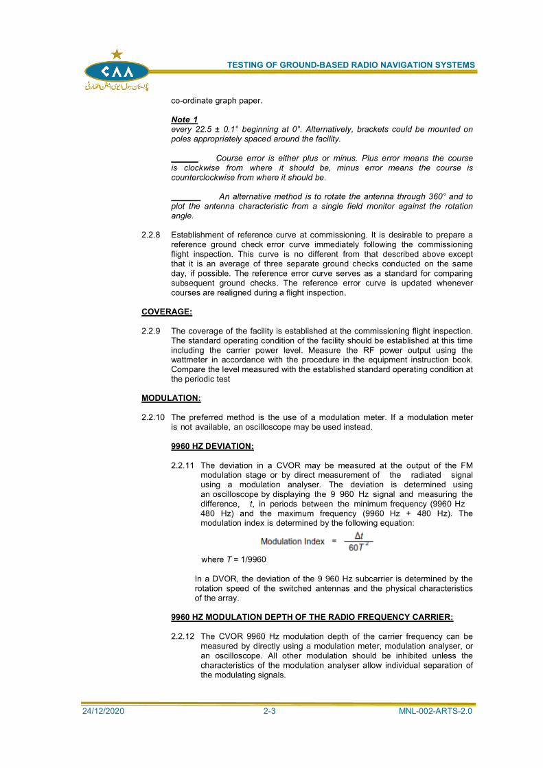
2.2.11 The deviation in a CVOR may be measured at the output of the FMmodulation stage or by direct measurement of the radiated signalusing a modulation analyser. The deviation is determined usingan oscilloscope by displaying the 9 960 Hz signal and measuring thedifference, t, in periods between the minimum frequency (9960 Hz480 Hz) and the maximum frequency (9960 Hz + 480 Hz). Themodulation index is determined by the following equation:
where T = 1/9960
In a DVOR, the deviation of the 9 960 Hz subcarrier is determined by therotation speed of the switched antennas and the physical characteristicsof the array.
9960 HZ MODULATION DEPTH OF THE RADIO FREQUENCY CARRIER:
2.2.12 The CVOR 9960 Hz modulation depth of the carrier frequency can bemeasured by directly using a modulation meter, modulation analyser, oran oscilloscope. All other modulation should be inhibited unless thecharacteristics of the modulation analyser allow individual separation ofthe modulating signals.
TESTING OF GROUND-BASED RADIO NAVIGATION SYSTEMS
24/12/2020 2-4 MNL-002-ARTS-2.0
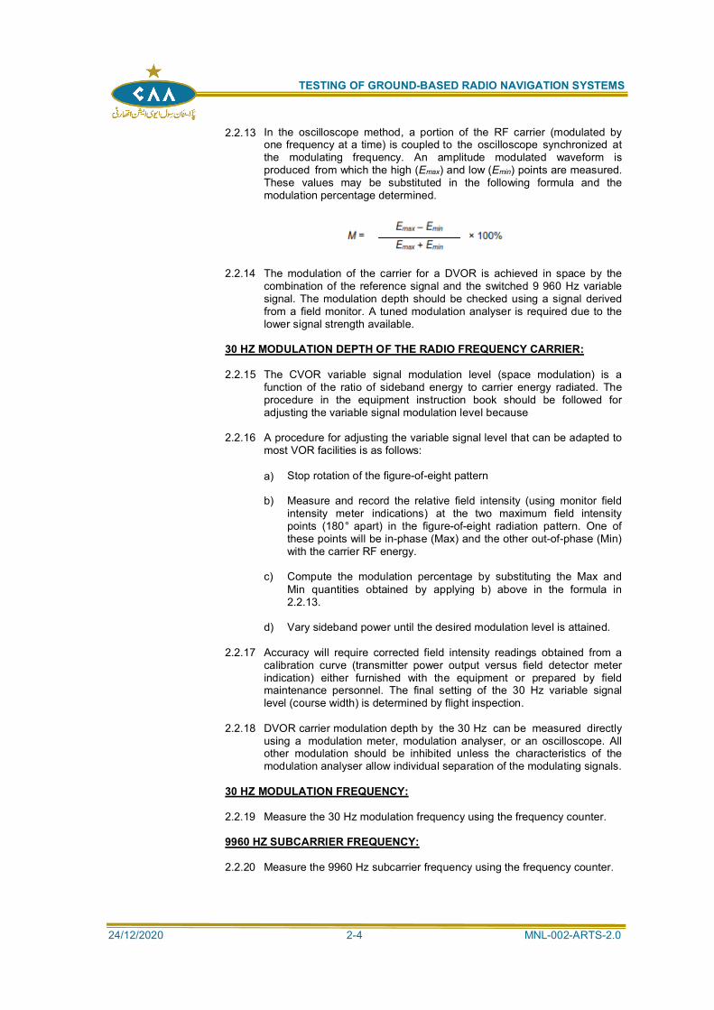
2.2.13 In the oscilloscope method, a portion of the RF carrier (modulated byone frequency at a time) is coupled to the oscilloscope synchronized atthe modulating frequency. An amplitude modulated waveform isproduced from which the high (Emax) and low (Emin) points are measured.These values may be substituted in the following formula and themodulation percentage determined.
2.2.14 The modulation of the carrier for a DVOR is achieved in space by thecombination of the reference signal and the switched 9 960 Hz variablesignal. The modulation depth should be checked using a signal derivedfrom a field monitor. A tuned modulation analyser is required due to thelower signal strength available.
30 HZ MODULATION DEPTH OF THE RADIO FREQUENCY CARRIER:
2.2.15 The CVOR variable signal modulation level (space modulation) is afunction of the ratio of sideband energy to carrier energy radiated. Theprocedure in the equipment instruction book should be followed foradjusting the variable signal modulation level because
2.2.16 A procedure for adjusting the variable signal level that can be adapted tomost VOR facilities is as follows:
a) Stop rotation of the figure-of-eight pattern
b) Measure and record the relative field intensity (using monitor fieldintensity meter indications) at the two maximum field intensitypoints (180° apart) in the figure-of-eight radiation pattern. One ofthese points will be in-phase (Max) and the other out-of-phase (Min)with the carrier RF energy.
c) Compute the modulation percentage by substituting the Max andMin quantities obtained by applying b) above in the formula in2.2.13.
d) Vary sideband power until the desired modulation level is attained.
2.2.17 Accuracy will require corrected field intensity readings obtained from acalibration curve (transmitter power output versus field detector meterindication) either furnished with the equipment or prepared by fieldmaintenance personnel. The final setting of the 30 Hz variable signallevel (course width) is determined by flight inspection.
2.2.18 DVOR carrier modulation depth by the 30 Hz can be measured directlyusing a modulation meter, modulation analyser, or an oscilloscope. Allother modulation should be inhibited unless the characteristics of themodulation analyser allow individual separation of the modulating signals.
30 HZ MODULATION FREQUENCY:
2.2.19 Measure the 30 Hz modulation frequency using the frequency counter.
9960 HZ SUBCARRIER FREQUENCY:
2.2.20 Measure the 9960 Hz subcarrier frequency using the frequency counter.
TESTING OF GROUND-BASED RADIO NAVIGATION SYSTEMS
24/12/2020 2-5 MNL-002-ARTS-2.0
CVOR AM MODULATION OF 9960 HZ SUBCARRIER:
2.2.21 Observe the 9 960 Hz subcarrier using an oscilloscope at the output ofthe FM modulator or after detection from a field monitor. Use the methoddescribed above to determine the AM modulation of the subcarrier withall other modulation off.
DVOR AM MODULATION OF 9960 HZ SUBCARRIER:
2.2.22 Observe the composite signal with an oscilloscope connected to a testreceiver or monitor and all other modulation off. Determine thepercentage of amplitude modulation using the method described above.
The limit for AM on the subcarrier in the far field, further than300 m (1000 ft) away, is less than 40 per cent. This limit corresponds toa limit of 55 per cent when the signal from a monitor antenna at the 80
instruction book for additional guidance on particular equipment.
SIDEBAND LEVEL OF THE HARMONICS OF THE 9960 HZ COMPONENT:
2.2.23 The level of the 9 960 Hz harmonics can be determined by using aspectrum analyser and observing the radiated signal of the VOR from afield monitor probe. CVOR measurements can also be made at theantenna feed point of the reference signal.
VOICE CHANNEL:
2.2.24 Peak modulation of voice channel. Connect an audio generator set to thenominal line level to the audio input of the VOR. Measure the peak modulationusing a modulation meter or the oscilloscope method described above
2.2.25 Audio frequency characteristics. Select a frequency of 1 000 Hz using an audiogenerator and establish a reference modulation level. Maintain the same outputlevel from the audio generator and vary the audio frequency between 300 Hz and3 000 Hz noting the modulation characteristics over the range.
2.2.26 Speech effect on normal navigation function. Operate the VOR in normal modewith all navigation modulation present. Apply the normal audio programme andobserve the station monitor for any effect on the navigation performance.
IDENTIFICATION:
2.2.27 Speed. Observe the identification signal envelope using an oscilloscope. The
2.2.28 Repetition. The repetition rate can be established by counting the repetition of thecode cycle over a fixed period or by measuring the time required for thecompletion of several cycles.
2.2.29 Tone. The identification tone can be measured directly using a frequencycounter.
2.2.30 Modulation depth. Measure the modulation depth using a modulation meter orthe oscilloscope method with the identification tone continuously on and no othermodulation present.
MONITORING:
2.2.31 Two methods are available to test the monitor performance. The first methodis the simulation of the monitor input signal by the use of test equipment; andthe second method is the adjustment of the transmitter to provide the required
TESTING OF GROUND-BASED RADIO NAVIGATION SYSTEMS
24/12/2020 2-6 MNL-002-ARTS-2.0
test signals. The use of discrete test equipment is the preferred method.Additional monitors may be provided in different equipment types. The
2.2.32 Bearing. Generate a VOR signal that equates to the monitored radial. Vary thephase of the variable signal relative to the reference signal to generate a positiveand negative bearing alarm. Record the phase difference.
2.2.33 Modulation. Apply a standard monitor input signal and vary the modulation ofthe 9 960 Hz and the 30 Hz signals to cause alarm conditions for either or bothof the navigation tones.
POLARIZATION:
2.2.34 This parameter is normally measured by flight inspection, but may be measuredon the ground if suitable equipment is available.
SPURIOUS MODULATION:
2.2.35 Spurious (unwanted) modulation should be as low as possible (0.5 per cent orless) to prevent possible course errors. This modulation level may be determinedby comparing AC voltage indications required to produce a known modulationlevel (only one modulation frequency applied) with the AC voltage indications,while audio input level controls (1 020 Hz, 10 kHz, and voice) are adjusted tozero. The modulation output meter may be used for these readings. Recordthe modulation value obtained
SITE INFRINGEMENT:
2.2.36 The site surrounding the VOR should be inspected at each maintenance visit forinfringements of the clear area surrounding the facility.
MAINTENANCE ACTIVITIES THAT REQUIRE FLIGHT INSPECTION:
2.2.37 Flight inspection is not required for all maintenance procedures or modificationsto the transmitting and monitoring equipment if field measurement and monitoringindications can be restored to the conditions that existed at commissioning orduring the last satisfactory flight test.
2.2.38 A flight test is required in the following situations before returning the VOR toservice:
a) realignment of magnetic north reference;
b) replacement of the antenna;
c) repositioning the field monitor antenna;
d) replacement of transmission lines of critical length;
e) change of operating frequency; and
f) environmental changes.
COURSE ERROR ANALYSIS:
2.2.39 Improper equipment adjustments or faulty equipment can result in a groundcheck error curve having periodic variations. These variations approximate theshape of sine waves and depending upon the total number of positive andnegative peaks above and below the zero course error line, are called duantal,quadrantal, or octantal error. These errors can appear singly or simultaneouslyin any combination. The Fourier analysis technique can be employed to
TESTING OF GROUND-BASED RADIO NAVIGATION SYSTEMS
24/12/2020 2-7 MNL-002-ARTS-2.0
determine the type and amount of error in an error curve if desired. The followingexamples apply for CVOR only.
2.2.40 Duantal error (two peaks, one positive and one negative) is caused byunwanted 30 Hz amplitude modulation of the RF carrier and/or improper RFphase relationship between sideband antenna currents of a pair. Possible causesof duantal error in a four-loop array are:
a) unequal electrical line lengths of paired transmission lines;
b) improper location of figure-of-eight radiation pattern Min points;
c) amplitude modulation of the 10 kHz signal at a 30 Hz rate; and/or
d) dissimilar antennas or antenna members elements.
2.2.41 Quadrantal error (four peaks, two positive and two negative) is caused byunwanted 60 Hz modulation of the RF carrier and/or antenna system faults.Possible causes of quadrantal error in a four-loop array are:
a) inequality of antenna pair currents;
b) misphasing of RF currents between antenna pairs;
c) unequal attenuation of sideband antenna feed lines; and/or
d) improper adjustment of the power amplifier stage of the transmitter.
2.2.42 Octantal error (eight peaks, four positives and four negatives) is found primarily inVOR facilities employing four (loop) antennas. This error results when they do notproduce a true figure-of-eight radiation pattern. End-plates on loops should beadjusted to reduce octantal error.
2.2.43 Reserved.
TEST EQUIPMENT:
2.2.44 The following is a suggested list of test equipment for use in maintaining VOR facilities:
b) audio oscillator;
c) VOR test generator;
d) frequency counter;
e) modulation analyser or modulation meter;
f) wattmeter, voltage standing wave ratio indicator or through-line wattmeter;
g) probe detector, VHF;
h) spectrum analyser.
2.3 FLIGHT TESTING:
GENERAL:
2.3.1 VORs should meet all requirements to be classified as unrestricted. The operatingagency may, after proper coordination, prescribe the use of the facility on a restricted
TESTING OF GROUND-BASED RADIO NAVIGATION SYSTEMS
24/12/2020 2-8 MNL-002-ARTS-2.0
basis and issue a NOTAM accordingly when a facility does not meet these operatingtolerances within a specific area.
FLIGHT TEST PERFORMANCE PARAMETERS:
2.3.2 Flight testing requirements are listed in Table I-2-3
FLIGHT TEST PROCEDURES:
SENSING:
2.3.3 This check is required at the beginning of the flight inspection and need not berepeated. The bearing of the aircraft from the station must be known. Select anappropriate radial and when the cross-pointer is centred, the indicator should
ROTATION:
2.3.4 Begin an orbit. The radial bearing as indicated should continually decrease for acounterclockwise orbit, or increase for a clockwise orbit. Sensing should bechecked before rotation. Incorrect sensing might cause the station rotation toappear reversed.
POLARIZATION EFFECT:
2.3.5 The polarization effect results from vertically polarized RF energy being radiated
ATTITUDE EFFECT METHOD:
2.3.6 The vertical polarization effect should be checked when flying directly to,or from, the facility, at a distance of 18.5 to 37 km (10 to 20 NM). Theaircraft should be rolled to a 30° bank, first to one side, then to the other,and returned to a straight level flight. Track and heading deviationsshould be kept to a minimum. Course deviation, as measured on therecording, is the indication of vertical polarization effect.
30° BANK, 360° TURN METHOD:
2.3.7 Vertical polarization may be checked by executing a 30° bank, 360° turn,18.5 to 37 km (10 to 20 NM) from the antenna. The turn should begin
ground checkpoint.
2.3.8 The recording should be marked at the start of the turn and at each 90°of heading change until the turn is completed. The turn should becompleted over the starting point and the recording marked. Therecording should show a smooth departure from and return to the
displaced from the original starting point when the vertical polarizationeffect is not present. Other excursions of the cross-pointer may beattributed to the vertical polarization effect. The effect of the wingshadowing the aircraft antenna should be considered in evaluating therecording.
PATTERN ACCURACY:
ALIGNMENT:
2.3.9 Alignment can be determined by flying an orbit or by flying a series of
TESTING OF GROUND-BASED RADIO NAVIGATION SYSTEMS
24/12/2020 2-9 MNL-002-ARTS-2.0
radials. The altitude selected for the flight should place the aircraft in themain lobe of the VOR.
2.3.10 The orbit should be flown at a height and range that allows the positionreference system to accurately determine the position of the aircraft. Thiswill require low, close-in orbits for theodolite-based position systems.Other automated systems will require the orbits to be conducted at agreater range to achieve the required accuracy. The orbit should havesufficient overlap to ensure that the measurement covers the complete360°. The alignment of the VOR is determined by averaging the errorthroughout the orbit. Judgement may be exercised where the tracking ofthe orbit is interrupted to determine the effect of the lost information onthe average alignment.
2.3.11 Alignment can also be determined by flying a series of radialapproaches. These approaches should be conducted at equal angulardisplacements around the facility. A minimum of eight radials isconsidered necessary to determine the alignment of the VOR.
BENDS:
2.3.12 A bend is determined by flying a radial pattern and comparing theindicated course against a position reference system. The error ismeasured against the correct magnetic azimuth of the radial. TheAnnex 10 SARPs do not contain absolute accuracy standards for theVOR signal-in-space but only planning examples for procedure design.The following values are often used as default values for proceduredesign. If these values are exceeded at commissioning, it does notimmediately result in a failure to meet the requirements, but anevaluation of the procedure design with the actual determined valuesshould be conducted. Deviations of the course due to bends should notexceed 3.5° from the computed average course alignment and shouldremain within 3.5° of the correct azimuth.
ROUGHNESS AND SCALLOPING ERROR:
2.3.13 Scalloping is a cyclic deviation of the course line. The frequency is highenough so that the deviation is averaged out and will not cause aircraftdisplacement. Roughness is a ragged irregular series of deviations.Momentary deviations of the course due to roughness, scalloping orcombinations thereof should not exceed 3.0° from the average course.
2.3.13.1 One way to systematically define and measure VOR accuracy is toconsider that scalloping and roughness correspond to control motionnoise (CMN) while bends and alignment errors are linked to pathfollowing error (PFE) and path following noise (PFN), where CMN, PFEand PFN are defined as the outputs of different filters. In order to filtershort duration disturbances, a 40-second sliding window technique maybe applied to the resulting filtered error components. The defaulttolerances are applied as:
Flyability:
2.3.14 Flyability is a subjective assessment by the pilot flying the inspection.Assessment of flyability should be performed on operational radials andduring procedures based on the VOR, using the VOR as the trackguidance source.
TESTING OF GROUND-BASED RADIO NAVIGATION SYSTEMS
24/12/2020 2-10 MNL-002-ARTS-2.0
COVERAGE:
2.3.15 Coverage of the VOR is the usable area within the operational service volumeand is determined during the various checks of the VOR. Additional flight checksare required to determine the distance from the facility at which satisfactorycoverage is obtained at the specified altitude
2.3.16 The coverage of a VOR can be affected by factors other than signal strength.Where out-of-tolerance roughness, scalloping, bends, alignment, and/orinterference render the facility unusable in certain areas, a restriction shouldresult which should be handled in the same manner as restricted coverage due tolack of signal strength.
MODULATION:
2.3.17 The modulation of the 30 Hz reference, 30 Hz variable and 9960 Hzsubcarrier should be measured during the flight inspection. Note that the rolesof the FM and AM signals are reversed between the CVOR and the DVOR.
VOICE CHANNEL:
2.3.18 Voice communications on the VOR frequency should be checked for clarity,signal strength, and effect on the course structure in the same manner asdescribed for identification checks. The audio level of voice communications isthe same as the level of the voice identification feature. Flight inspectionpersonnel should maintain surveillance of the quality and coverage of recordedvoice transmissions (automatic terminal information service (ATIS) or othertranscribed voice service) and ensure that there is no detrimental effect on theperformance of the VOR. Comments and deficiencies should be included in theappropriate flight inspection reports.
2.3.19 Speech effect on normal navigation functions. Observe the indicated bearinginformation during a stable approach flight and determine if the bearinginformation is affected by the voice transmission.
IDENTIFICATION:
2.3.20 The identification signal should be inspected for correctness, clarity, and possibledetrimental effect on the course structure. This check should be performed whileflying on-course and within radio line-of-sight of the station. Observe the courserecording to determine if either code or voice identification affects the coursestructure. If course roughness is suspected, the identical track should be flownagain with the identification turned off. Maintenance personnel should beadvised immediately if it is determined that the course characteristics areaffected by the identification signal.
2.3.21 The audible transmission of simultaneous voice/code identification signals shouldappear to be equal in volume to the user. The voice identification is not utilizedduring ground-to-air broadcasts on the VOR frequency, but the codedidentification should be audible in the background.
BEARING MONITOR:
2.3.22 The requirements for checking the monitor are as follows:a) during commissioning inspections; and
b) during subsequent inspections, if the alignment at the referencecheckpoint has changed more than one degree from the alignment lastestablished and the monitor has not alarmed
2.3.23 The check is made over the reference checkpoint at the same altitude as thatused to establish the reference checkpoint. Position the aircraft inbound or
TESTING OF GROUND-BASED RADIO NAVIGATION SYSTEMS
24/12/2020 2-11 MNL-002-ARTS-2.0
outbound and activate the event mark exactly over the checkpoint while thefollowing course conditions exist:
a) with the course in the normal operating condition;
b) with the course shifted to the alarm point;
c) with the course shifted to the alarm point to the opposite direction from b)above; or
d) with the course returned to the normal operating condition.
2.3.24 The course alignment should be compared, in each of these conditions, byreference to the recordings to determine the amplitude of shift to the alarm pointand to verify the return to normal.
2.3.25 Where dual monitors are installed, follow the procedure for single monitor checkabove, except in steps b) and c) the course should be shifted in each directionuntil both monitors alarm. Determine the amplitude of course-shift required toalarm both monitors.
REFERENCE CHECKPOINT:
2.3.26 A checkpoint should be selected during the commissioning inspection on or closeto the monitor radial (usually 090 or 270 degrees) and located within 18.5 to 37km (10 to 20 NM) of the antenna. This checkpoint should be used in establishingcourse alignment and should serve as a reference point for subsequentinspections of alignment, monitors, course sensitivity and modulationmeasurements. Course alignment and sensitivity should normally be adjustedwith reference to this checkpoint. Adjustments made elsewhere will require arecheck of these parameters at this reference checkpoint.
2.3.27 The flight inspector should record a description of the reference checkpoint thatincludes the azimuth to the nearest tenth of a degree, the distance from thefacility, and the mean sea level (MSL) altitude, which is usually 460 m (1 500 ft)above the antenna. This data should be revised any time the referencecheckpoint is re-established. The final course alignment error, measured at thereference checkpoint, should be recorded on the facility data sheet forsubsequent reference in order to determine the necessity for a complete monitor
STANDBY POWER:
2.3.28 Standby power, when installed, should be checked during the commissioninginspection. This is not necessary for some types of standby power installations,e.g. float-charged battery supplies where there is no possibility of performancevariation when operating on standby power. Subsequent inspections should notbe required unless there is reported evidence of facility deterioration while thissource of power is in use. The following items should be evaluated whileoperating on standby power:
a) course alignment (one radial);
b) course structure; andc) modulations.
2.3.29 The inspections are to be performed when flying a portion of a radial with thestation operating on normal power, and then repeating the check at the samealtitude and over the same ground track with the station operating on standbypower.
TESTING OF GROUND-BASED RADIO NAVIGATION SYSTEMS
24/12/2020 2-12 MNL-002-ARTS-2.0
STANDBY EQUIPMENT:
2.3.30 Both transmitters should be checked against each required item of Table I-2-3.These checks may be performed using radial flights and a single alignment orbit.
2.3.31 Reserved
EVALUATION OF OPERATIONAL PROCEDURES:
RADIALS:
2.3.32 Radials used, or proposed for use, for IFR should be inspected todetermine their capability to support the procedure. On commissioninginspections, a selection of radials proposed for IFR use should beinspected. The selection should be based on the following criteria:
a) All radials supporting instrument approach procedures should beselected.
b) Radials should be selected from areas of poor performanceindicated by the orbit inspection.
c) Any radials where the coverage may be affected by terrain shouldbe selected.
d) At least one radial should be selected from each quadrant, ifappropriate. In general, this should include the longest and lowestradials.
Routine inspection requirements are contained in the followingparagraphs.
EN-ROUTE RADIALS (AIRWAYS, OFF-AIRWAY ROUTES, SUBSTITUTEROUTES)
2.3.33 En-route radials should be flown either inbound or outbound, along theirentire length from the facility to the extremity of their intended use, at theminimum altitude for the associated airway or route as published. Theminimum altitude for flying en-route radials, predicated on terminalfacilities, is 300 m (1000 ft) above the highest terrain or obstruction alongthe radial to a distance of 46.3 km (25 NM). The aircraft should be flownon the electronic radial and the position of the aircraft should berecorded using a position reference system.
2.3.34 Reference, variable and 9960 Hz modulations and the verticalpolarization effect should be checked at least once on each airway anddirect-route radial. Signal strength, course deviation and aircraft positionshould be recorded throughout the radial flight.
2.3.35 Course structure and alignment should be determined by analysis of therecordings. The recordings should also be analysed for possibleundesirable close-in or over-station characteristics to determine that useof the facility for approach, holding, etc., is not adversely affected
TERMINAL RADIALS (APPROACH, MISSED APPROACH, STANDARDINSTRUMENT DEPARTURE (SID):
2.3.36 Approach radials should be evaluated at a distance that includes theprocedure turn, holding pattern and missed approach on commissioninginspections. The approach radial should be flown 30 m (100 ft) belowspecified altitudes. Site and commissioning inspections require twoadditional radials 5° either side of the approach radial to be flown and
TESTING OF GROUND-BASED RADIO NAVIGATION SYSTEMS
24/12/2020 2-13 MNL-002-ARTS-2.0
analysed with the same criteria as the approach radial. This needs to beperformed only if the approach radial shows performance near the setaccuracy requirement. Radials used to support SID procedures shouldbe evaluated to the extent to which they are used.
INTERSECTIONS:
2.3.37 Adjacent facilities that provide intersections should be inspected todetermine their capability to support the intersection. Reliable facilityperformance and course guidance at the approved minimum holdingaltitude (MHA) should exist. Minimum signal strength should exist forthe radial(s) forming the intersection within 7.4 km (4 NM) or 4.5°,whichever is greater, each side of the geographical location of theintersection fix.
2.3.38 Identification from each facility forming the intersection should be clearand distinct. The signal from each facility should be free frominterference at all altitudes below the maximum authorized altitude forholding. A minimum reception altitude should be established for theintersection, which is normally determined by the facility providing theweakest signal.
All minimum en-route altitudes are to be corrected to andreported as true altitudes above mean sea level. All intersections prior tobeing published and authorized for use are to be flight inspected againstthe requirements stated above. Routine inspections of intersections canbe accomplished adequately by recording an airway radial of one facilityand the transition from other facilities forming the fix. Routineinspections can therefore be conducted concurrently with airwayradials. Departure from the airway radial that is being inspected toevaluate another radial which is part of the fix is not required, unlessdetailed investigations become necessary.
CROSS-CHECK RADIALS:
2.3.39 Commissioning and routine flight inspections of cross-check radials arenot required provided there is sufficient flight inspection data to supportthe publication of these radials. The radial(s) should be inspected prior tobeing authorized for use if cross-check radials are requested for use inareas outside of the operational service volume of the facility(ies) forwhich supporting flight inspection data is not available. Thereafter, flightinspections are not required.
2.3.40 Reserved.
TEST EQUIPMENT:
2.3.41 The aircraft should be fitted with a typical VOR receiver and antenna system. The powerlevel into the receiver is used as the normal reference parameter for the determination offield strength. The power level into the receiver can be converted to absolute field strengthif the antenna factor and cable losses are known. Refer to Chapter 1, Attachment A, forguidance on determining antenna performance.
2.3.42 Reserved
ANALYSIS:
COURSE STRUCTURE:
2.3.43 Roughness, scalloping, and bends are displayed as deviations of the cross-pointer. Roughness will show as a series of ragged irregular deviations;scalloping, as a series of smooth rhythmic deviations. The frequency of each is
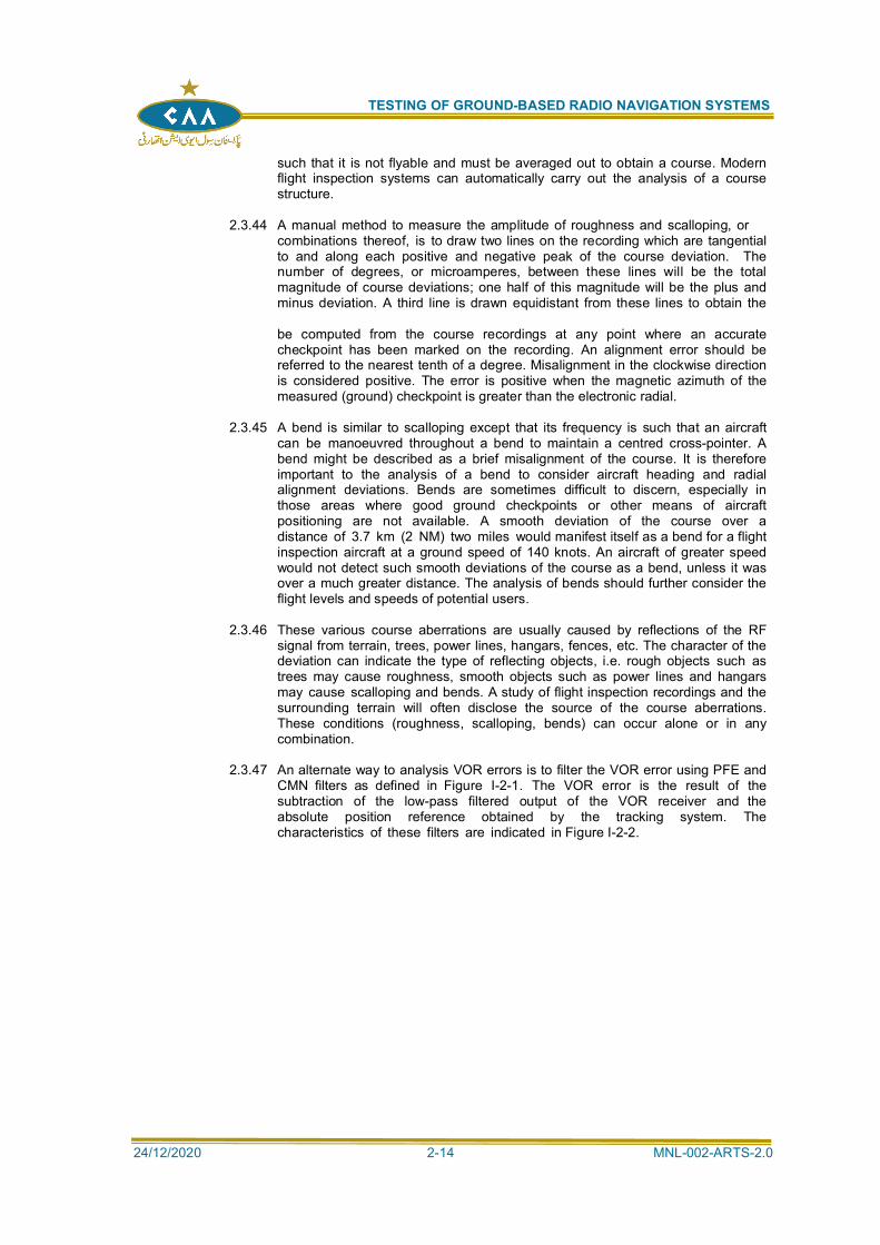
TESTING OF GROUND-BASED RADIO NAVIGATION SYSTEMS
24/12/2020 2-14 MNL-002-ARTS-2.0
such that it is not flyable and must be averaged out to obtain a course. Modernflight inspection systems can automatically carry out the analysis of a coursestructure.
2.3.44 A manual method to measure the amplitude of roughness and scalloping, orcombinations thereof, is to draw two lines on the recording which are tangentialto and along each positive and negative peak of the course deviation. Thenumber of degrees, or microamperes, between these lines will be the totalmagnitude of course deviations; one half of this magnitude will be the plus andminus deviation. A third line is drawn equidistant from these lines to obtain the
be computed from the course recordings at any point where an accuratecheckpoint has been marked on the recording. An alignment error should bereferred to the nearest tenth of a degree. Misalignment in the clockwise directionis considered positive. The error is positive when the magnetic azimuth of themeasured (ground) checkpoint is greater than the electronic radial.
2.3.45 A bend is similar to scalloping except that its frequency is such that an aircraftcan be manoeuvred throughout a bend to maintain a centred cross-pointer. Abend might be described as a brief misalignment of the course. It is thereforeimportant to the analysis of a bend to consider aircraft heading and radialalignment deviations. Bends are sometimes difficult to discern, especially inthose areas where good ground checkpoints or other means of aircraftpositioning are not available. A smooth deviation of the course over adistance of 3.7 km (2 NM) two miles would manifest itself as a bend for a flightinspection aircraft at a ground speed of 140 knots. An aircraft of greater speedwould not detect such smooth deviations of the course as a bend, unless it wasover a much greater distance. The analysis of bends should further consider theflight levels and speeds of potential users.
2.3.46 These various course aberrations are usually caused by reflections of the RFsignal from terrain, trees, power lines, hangars, fences, etc. The character of thedeviation can indicate the type of reflecting objects, i.e. rough objects such astrees may cause roughness, smooth objects such as power lines and hangarsmay cause scalloping and bends. A study of flight inspection recordings and thesurrounding terrain will often disclose the source of the course aberrations.These conditions (roughness, scalloping, bends) can occur alone or in anycombination.
2.3.47 An alternate way to analysis VOR errors is to filter the VOR error using PFE andCMN filters as defined in Figure I-2-1. The VOR error is the result of thesubtraction of the low-pass filtered output of the VOR receiver and theabsolute position reference obtained by the tracking system. Thecharacteristics of these filters are indicated in Figure I-2-2.
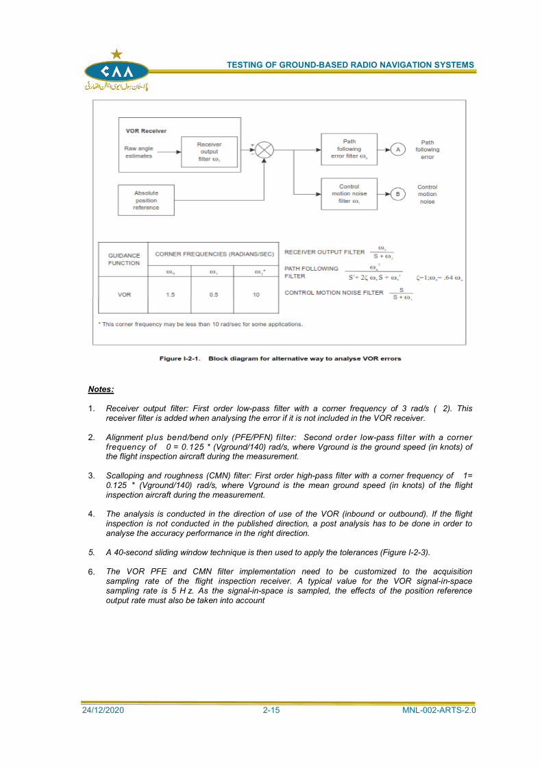
TESTING OF GROUND-BASED RADIO NAVIGATION SYSTEMS
24/12/2020 2-15 MNL-002-ARTS-2.0
Notes:
1. Receiver output filter: First order low-pass filter with a corner frequency of 3 rad/s ( 2). Thisreceiver filter is added when analysing the error if it is not included in the VOR receiver.
2. Alignment plus bend/bend only (PFE/PFN) filter: Second order low-pass filter with a cornerfrequency of 0 = 0.125 * (Vground/140) rad/s, where Vground is the ground speed (in knots) ofthe flight inspection aircraft during the measurement.
3. Scalloping and roughness (CMN) filter: First order high-pass filter with a corner frequency of 1=0.125 * (Vground/140) rad/s, where Vground is the mean ground speed (in knots) of the flightinspection aircraft during the measurement.
4. The analysis is conducted in the direction of use of the VOR (inbound or outbound). If the flightinspection is not conducted in the published direction, a post analysis has to be done in order toanalyse the accuracy performance in the right direction.
5. A 40-second sliding window technique is then used to apply the tolerances (Figure I-2-3).
6. The VOR PFE and CMN filter implementation need to be customized to the acquisitionsampling rate of the flight inspection receiver. A typical value for the VOR signal-in-spacesampling rate is 5 H z. As the signal-in-space is sampled, the effects of the position referenceoutput rate must also be taken into account
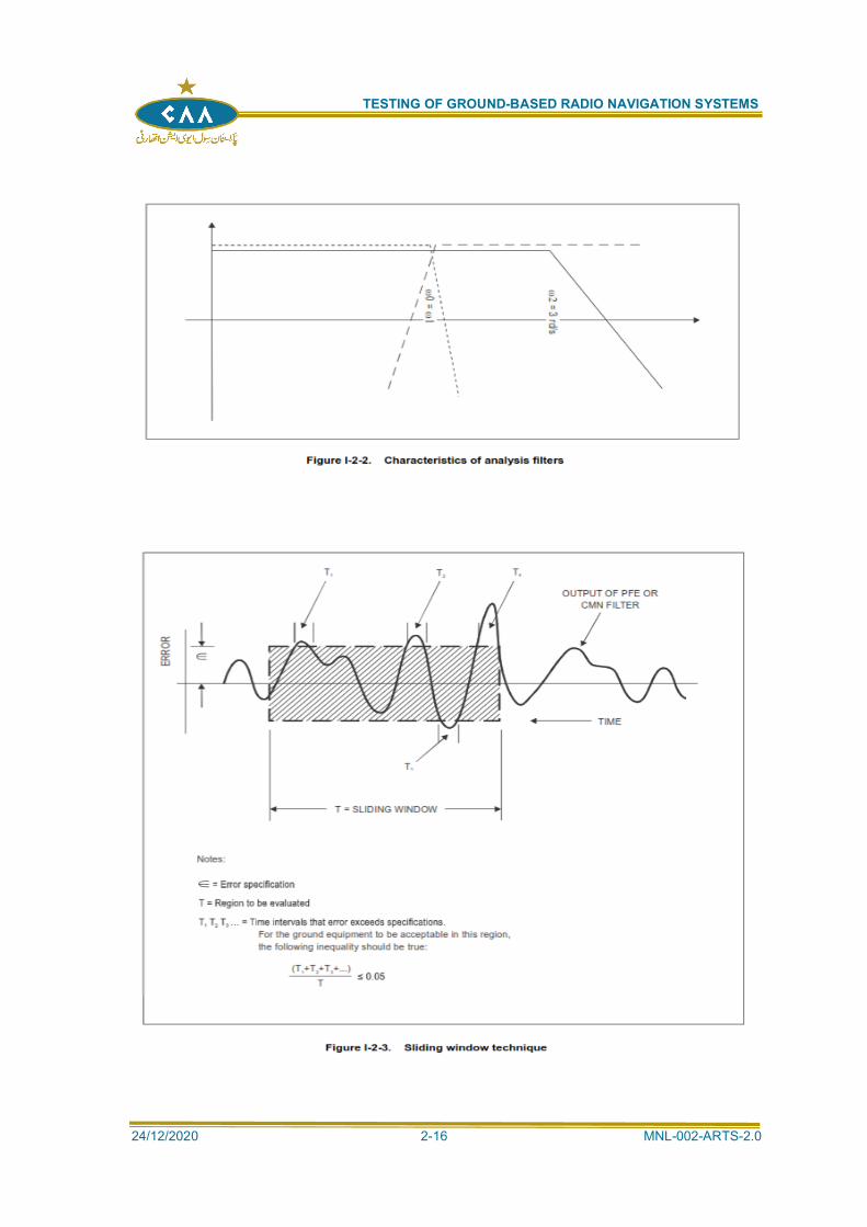
TESTING OF GROUND-BASED RADIO NAVIGATION SYSTEMS
24/12/2020 2-16 MNL-002-ARTS-2.0
TESTING OF GROUND-BASED RADIO NAVIGATION SYSTEMS
24/12/2020 2-17 MNL-002-ARTS-2.0
APPLICATION OF TOLERANCES:
2.3.48 The application of bend criteria should consider the navigation system accuracy,which is based partly on the typical maximum course displacement of 3.5° (bendtolerance) and the maximum distance an aircraft is expected to depart from anestablished course. The displacement of the course by a bend should not exceed3.5° from either the correct magnetic azimuth or the on-course average, asprovided by the facility, in order to satisfy these factors. The following twoexamples are offered for clarification:
a)
occurs singly or in series
course by a bend of +1.5° is allowable. This results in a +3.5° displacementfrom the correct magnetic azimuth. Since a bend displacement of the course
displacement from the correct magnetic azimuth.
2.3.49 When roughness, or scalloping, or a combination is superimposed on the bend,
of such aberrations. This can result in a momentary displacement of the courseof 6.5° where 3.0° of roughness is superimposed on a bend of 3.5°. Such acondition is highly unlikely; however, consideration should be given to thesuitability of the facility in the areas of such occurrence.
2.3.50 The criteria for roughness and scalloping should not be applied strictly as a plusand minus factor, but as a maximum deviation from the course. Roughness andscalloping normally occur in a series. Where it is apparent that a rapid deviationoccurs only on one side of the course, rather than in a series, the criteria shouldbe applied as a plus factor, or a minus factor, as applicable. (See Figures I-2-4and I-2-5.)
2.3.51 When using the PFE/PFN/CMN technique, the following defaults are applied:
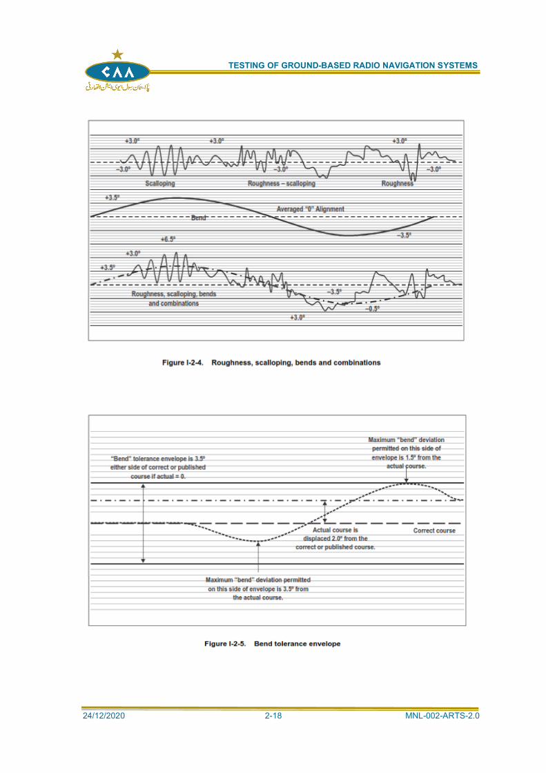
TESTING OF GROUND-BASED RADIO NAVIGATION SYSTEMS
24/12/2020 2-18 MNL-002-ARTS-2.0
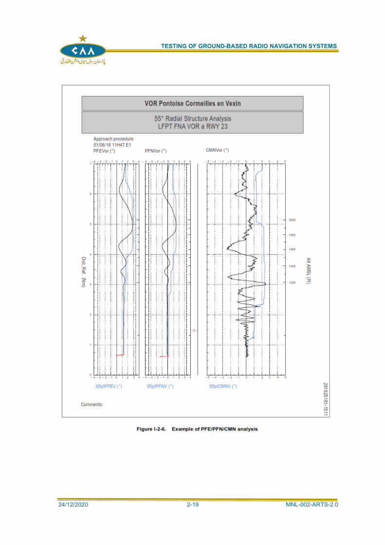
TESTING OF GROUND-BASED RADIO NAVIGATION SYSTEMS
24/12/2020 2-19 MNL-002-ARTS-2.0
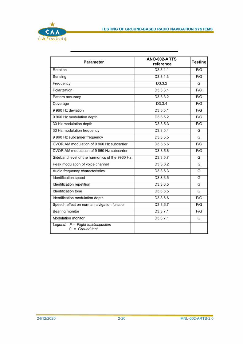
TESTING OF GROUND-BASED RADIO NAVIGATION SYSTEMS
24/12/2020 2-20 MNL-002-ARTS-2.0
Parameter ANO-002-ARTS reference Testing
Rotation D3.3.1.1 F/G
Sensing D3.3.1.3 F/G
Frequency D3.3.2 G
Polarization D3.3.3.1 F/G
Pattern accuracy D3.3.3.2 F/G
Coverage D3.3.4 F/G
9 960 Hz deviation D3.3.5.1 F/G
9 960 Hz modulation depth D3.3.5.2 F/G
30 Hz modulation depth D3.3.5.3 F/G
30 Hz modulation frequency D3.3.5.4 G
9 960 Hz subcarrier frequency D3.3.5.5 G
CVOR AM modulation of 9 960 Hz subcarrier D3.3.5.6 F/G
DVOR AM modulation of 9 960 Hz subcarrier D3.3.5.6 F/G
Sideband level of the harmonics of the 9960 Hz D3.3.5.7 G
Peak modulation of voice channel D3.3.6.2 G
Audio frequency characteristics D3.3.6.3 G
Identification speed D3.3.6.5 G
Identification repetition D3.3.6.5 G
Identification tone D3.3.6.5 G
Identification modulation depth D3.3.6.6 F/G
Speech effect on normal navigation function D3.3.6.7 F/G
Bearing monitor D3.3.7.1 F/G
Modulation monitor D3.3.7.1 G
Legend: F = Flight test/inspectionG = Ground test
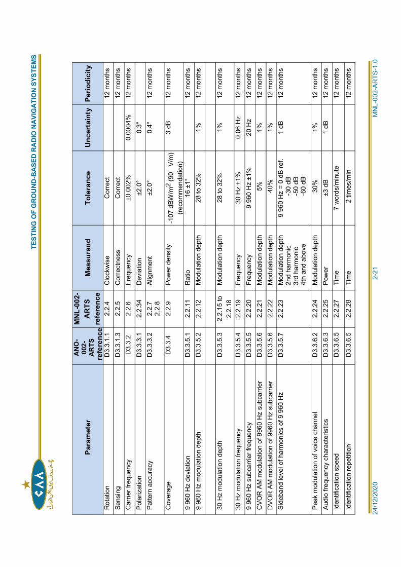
TEST
ING
OF
GRO
UND
-BA
SED
RADI
O N
AVIG
ATI
ON
SYST
EMS
2
4/12
/202
0
2
-21
M
NL-
002-
ARTS
-1.0
Para
met
erAN
O-
002-
ARTS
refe
renc
e
MN
L-00
2-A
RTS
refe
renc
eM
easu
rand
Tole
ranc
eU
ncer
tain
tyPe
riodi
city
Rot
atio
n D
3.3.
1.1
2.2.
4 C
lock
wis
e C
orre
ct
12
mon
ths
Sens
ing
D3.
3.1.
3 2.
2.5
Cor
rect
ness
C
orre
ct
12
mon
ths
Car
rier f
requ
ency
D
3.3.
2 2.
2.6
Freq
uenc
y ±0
.002
%
0.00
04%
12
mon
ths
Pola
rizat
ion
D3.
3.3.
1 2.
2.34
D
evia
tion
±2.0
° 0.
3°Pa
ttern
acc
urac
y D
3.3.
3.2
2.2.
72.
2.8
Alig
nmen
t ±2
.0°
0.4°
12
mon
ths
Cov
erag
e D
3.3.
4 2.
2.9
Pow
er d
ensi
ty-1
07 d
BW/m
2(9
0V/
m)
(reco
mm
enda
tion)
3 dB
12
mon
ths
9 96
0 H
z de
viat
ion
D3.
3.5.
1 2.
2.11
R
atio
16
±1°
12 m
onth
s9
960
Hz
mod
ulat
ion
dept
h D
3.3.
5.2
2.2.
12
Mod
ulat
ion
dept
h 28
to 3
2%
1%
12 m
onth
s
30 H
z m
odul
atio
n de
pth
D3.
3.5.
3 2.
2.15
to2.
2.18
Mod
ulat
ion
dept
h 28
to 3
2%
1%
12 m
onth
s
30 H
z m
odul
atio
n fre
quen
cy
D3.
3.5.
4 2.
2.19
Fr
eque
ncy
30 H
z ±1
%
0.06
Hz
12 m
onth
s9
960
Hz
subc
arrie
r fre
quen
cy
D3.
3.5.
5 2.
2.20
Fr
eque
ncy
9 96
0 H
z ±1
%
20 H
z 12
mon
ths
CVO
R A
M m
odul
atio
n of
996
0 H
z su
bcar
rier
D3.
3.5.
6 2.
2.21
M
odul
atio
n de
pth
5%
1%
12 m
onth
sD
VOR
AM
mod
ulat
ion
of 9
960
Hz
subc
arrie
r D
3.3.
5.6
2.2.
22
Mod
ulat
ion
dept
h40
%
1%
12 m
onth
sSi
deba
nd le
vel o
f har
mon
ics
of 9
960
Hz
D3.
3.5.
7 2.
2.23
M
odul
atio
n de
pth
2nd
harm
onic
3rd
harm
onic
4th
and
abov
e
9 96
0 H
z =
0 dB
ref.
-30
dB-5
0 dB
-60
dB
1 dB
12
mon
ths
Peak
mod
ulat
ion
of v
oice
cha
nnel
D
3.3.
6.2
2.2.
24
Mod
ulat
ion
dept
h30
%
1%
12 m
onth
sAu
dio
frequ
ency
cha
ract
eris
tics
D3.
3.6.
3 2.
2.25
Po
wer
±3
dB
1 dB
12
mon
ths
Iden
tific
atio
n sp
eed
D3.
3.6.
5 2.
2.27
Ti
me
7 w
ords
/min
ute
12
mon
ths
Iden
tific
atio
n re
petit
ion
D3.
3.6.
5 2.
2.28
Ti
me
2 tim
es/m
in
12
mon
ths
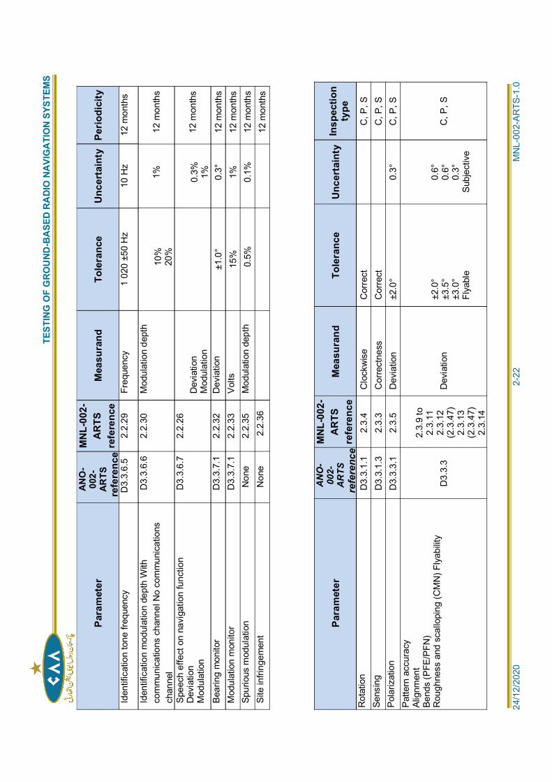
TEST
ING
OF
GRO
UND
-BA
SED
RADI
O N
AVIG
ATI
ON
SYST
EMS
2
4/12
/202
0
2
-22
M
NL-
002-
ARTS
-1.0
Para
met
erAN
O-
002-
ARTS
refe
renc
e
MN
L-00
2-A
RTS
refe
renc
eM
easu
rand
Tole
ranc
eU
ncer
tain
tyPe
riodi
city
Iden
tific
atio
n to
ne fr
eque
ncy
D3.
3.6.
5 2.
2.29
Fr
eque
ncy
1 02
0 ±5
0 H
z 10
Hz
12 m
onth
s
Iden
tific
atio
n m
odul
atio
n de
pth
With
com
mun
icat
ions
cha
nnel
No
com
mun
icat
ions
chan
nel
D3.
3.6.
6 2.
2.30
M
odul
atio
n de
pth
10%
20%
1%
12 m
onth
s
Spee
ch e
ffect
on
navi
gatio
n fu
nctio
nD
evia
tion
Mod
ulat
ion
D3.
3.6.
7 2.
2.26
Dev
iatio
nM
odul
atio
n0.
3% 1%12
mon
ths
Bear
ing
mon
itor
D3.
3.7.
1 2.
2.32
D
evia
tion
±1.0
° 0.
3°
12 m
onth
sM
odul
atio
n m
onito
r D
3.3.
7.1
2.2.
33
Volts
15%
1%
12
mon
ths
Spur
ious
mod
ulat
ion
Non
e 2.
2.35
M
odul
atio
n de
pth
0.5%
0.
1%
12 m
onth
sSi
te in
fring
emen
t N
one
2.2.
36
12
mon
ths
Para
met
erA
NO
-00
2-A
RTS
refe
renc
e
MN
L-00
2-A
RTS
refe
renc
eM
easu
rand
Tole
ranc
eU
ncer
tain
tyIn
spec
tion
type
Rot
atio
nD
3.3.
1.1
2.3.
4 C
lock
wis
e C
orre
ct
C
, P, S
Sens
ing
D3.
3.1.
3 2.
3.3
Cor
rect
ness
C
orre
ct
C
, P, S
Pola
rizat
ion
D3.
3.3.
1 2.
3.5
Dev
iatio
n ±2
.0°
0.3°
C
, P, S
Patte
rn a
ccur
acy
Alig
nmen
tBe
nds
(PFE
/PFN
)R
ough
ness
and
sca
llopi
ng (C
MN
) Fly
abilit
yD
3.3.
3
2.3.
9 to
2.3.
112.
3.12
(2.3
.47)
2.3.
13(2
.3.4
7)2.
3.14
Dev
iatio
n±2
.0°
±3.5
°±3
.0°
Flya
ble
0.6°
0.6°
0.3°
Subj
ectiv
e
C, P
, S
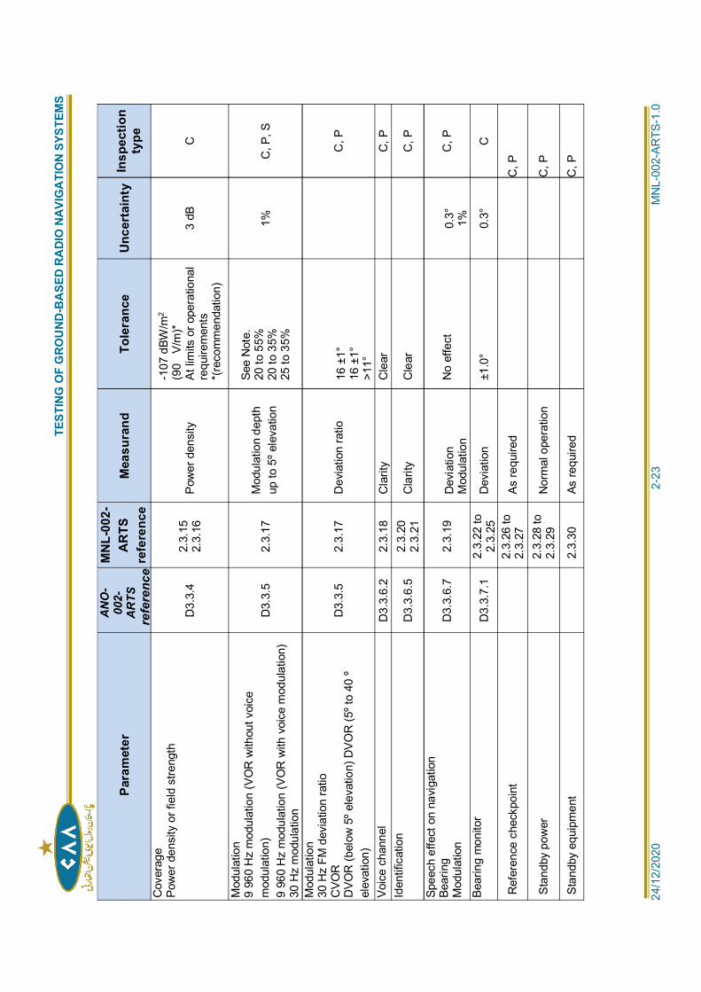
TEST
ING
OF
GRO
UND
-BA
SED
RADI
O N
AVIG
ATI
ON
SYST
EMS
2
4/12
/202
0
2
-23
M
NL-
002-
ARTS
-1.0
Para
met
erA
NO
-00
2-A
RTS
refe
renc
e
MN
L-00
2-A
RTS
refe
renc
eM
easu
rand
Tole
ranc
eU
ncer
tain
tyIn
spec
tion
type
Cov
erag
ePo
wer
den
sity
or f
ield
stre
ngth
D3.
3.4
2.3.
152.
3.16
Pow
er d
ensi
ty
-107
dBW
/m2
(90
V/m
)*At
lim
its o
r ope
ratio
nal
requ
irem
ents
*(re
com
men
datio
n)
3 dB
C
Mod
ulat
ion
9 96
0 H
z m
odul
atio
n (V
OR
with
out v
oice
mod
ulat
ion)
9 96
0 H
z m
odul
atio
n (V
OR
with
voi
ce m
odul
atio
n)30
Hz
mod
ulat
ion
D3.
3.5
2.3.
17M
odul
atio
n de
pth
up to
5º e
leva
tion
See
Not
e.20
to 5
5%20
to 3
5%25
to 3
5%1%
C
, P, S
Mod
ulat
ion
30 H
z FM
dev
iatio
n ra
tioC
VOR
DVO
R (b
elow
5º e
leva
tion)
DVO
R (5
º to
40 º
elev
atio
n)
D3.
3.5
2.3.
17
Dev
iatio
n ra
tio16
±1°
16 ±
1°>1
1°
C
, P
Voic
e ch
anne
lD
3.3.
6.2
2.3.
18
Cla
rity
Cle
ar
C
, PId
entif
icat
ion
D3.
3.6.
52.
3.20
2.3.
21C
larit
y C
lear
C, P
Spee
ch e
ffect
on
navi
gatio
nBe
arin
gM
odul
atio
nD
3.3.
6.7
2.3.
19D
evia
tion
Mod
ulat
ion
No
effe
ct0.
3° 1%C
, P
Bear
ing
mon
itor
D3.
3.7.
12.
3.22
to2.
3.25
Dev
iatio
n ±1
.0°
0.3°
C
Ref
eren
ce c
heck
poin
t2.
3.26
to2.
3.27
As re
quire
d
C
, P
Stan
dby
pow
er2.
3.28
to2.
3.29
Nor
mal
ope
ratio
n
C
, P
Stan
dby
equi
pmen
t
2.3.
30
As re
quire
d
C
, P
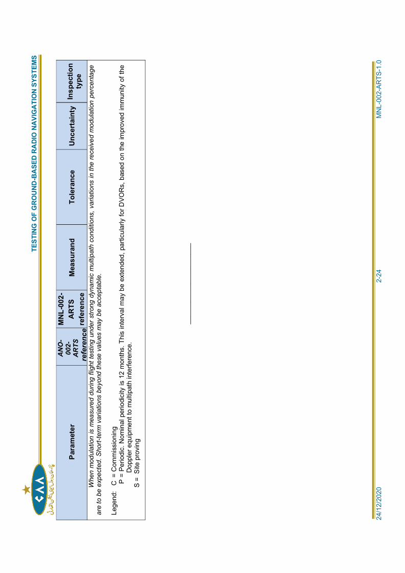
TEST
ING
OF
GRO
UND
-BA
SED
RADI
O N
AVIG
ATI
ON
SYST
EMS
2
4/12
/202
0
2
-24
M
NL-
002-
ARTS
-1.0
Para
met
erA
NO
-00
2-A
RTS
refe
renc
e
MN
L-00
2-A
RTS
refe
renc
eM
easu
rand
Tole
ranc
eU
ncer
tain
tyIn
spec
tion
type
Whe
n m
odul
atio
n is
mea
sure
d du
ring
fligh
t tes
ting
unde
r stro
ng d
ynam
ic m
ultip
ath
cond
ition
s, v
aria
tions
in th
e re
ceiv
ed m
odul
atio
n pe
rcen
tage
are
to b
e ex
pect
ed. S
hort-
term
var
iatio
ns b
eyon
d th
ese
valu
es m
ay b
e ac
cept
able
.
Lege
nd:
C =
Com
mis
sion
ing
P
= P
erio
dic.
Nom
inal
per
iodi
city
is 1
2 m
onth
s. T
his
inte
rval
may
be
exte
nded
, par
ticul
arly
for D
VOR
s, b
ased
on
the
impr
oved
imm
unity
of t
heD
oppl
er e
quip
men
t to
mul
tipat
h in
terfe
renc
e.
S =
Site
pro
ving
____
____
____
____
____
__
TESTING OF GROUND-BASED RADIO NAVIGATION SYSTEMS
24/12/2020 3-1 MNL-002-ARTS-2.0
Chapter 3
DISTANCE MEASURING EQUIPMENT (DME)
3.1 INTRODUCTION:
GENERAL:
3.1.1 This chapter provides guidance on flight and ground testing requirements applicable tothe standard distance measuring equipment (DME/N), as specified in ANO-002-ARTS,D3.5. The principles upon which the DME functions are based are such that the accuracyof the distance indications is essentially independent of the ground equipment-radiatedfield pattern. Consequently, the determination of correct ground equipment performancecan generally be made with the ground monitoring and maintenance equipment in
documentation. Many of the Annex 10 parameters can also be tested in an aircraft withan appropriate airborne system.
SYSTEM DESCRIPTION:
3.1.2 The DME system provides continuous distance information to an aircraft during executionof approach, departure, or en-route phases of flight in accordance with publishedprocedures. The signals can be interpreted either by the pilot from the display or inputdirectly into the flight management system (FMS).
TESTING REQUIREMENTS:
3.1.3 A summary of testing requirements is given is Table I-3-1.
3.2 GROUND TESTING:
GENERAL:
3.2.1 The parameters of the ground equipment that should be regularly checked are indicatedin Table I-3-2. The suggested periodicities are given as general guidance and may
experience. The procedures and test equipment to be employed in ground testing aDME transponder vary according to the commercial product involved. Guidance may be
GROUND PERFORMANCE PARAMETERS:
3.2.2 Ground test requirements are listed in Table I-3-2.
GROUND TEST PROCEDURES:
3.2.3 Recommended general instructions for testing of DME specific parameters are providedin the following paragraphs. The DME should be checked in accordance with the test
3.2.4 Transmitter frequency stability. Use the frequency counter to measure the transmitter
the frequency as required.
3.2.5 Pulse spectrum. Use the spectrum analyser to measure the spectrum of the output pulse
correct the modulation level (pedestal and Gaussian pulse) and adjust the transmitterstages if provided. Note the output power and pulse shape during adjustments.
TESTING OF GROUND-BASED RADIO NAVIGATION SYSTEMS
24/12/2020 3-2 MNL-002-ARTS-2.0
3.2.6 Pulse shape. Use the oscilloscope to measure the shape of the output pulse according to
refer to the adjustments of the output pulse spectrum in the paragraph above. Afteradjusting the pulse shape, it is very important to recheck the time decay. Check the pulseamplitude.
3.2.7 Pulse spacing. Use the oscilloscope to measure the spacing of the output pulse
are generally not provided.
3.2.8 Peak power output. Use the peak power meter and the calibrated load, or the variableattenuator when available, to measure the peak power output of the transmitter according
adjustments of the Gaussian modulation pulse shape and transmitter stages in theprevious paragraphs if adjustment is necessary. After adjustment, the time delay andpulse shape should be rechecked. Tolerances up to ±1dB of the power output areacceptable because these variations result in a change of the operational range by only10 per cent. It is more important to obtain the output pulse spectrum and pulse shapewithin the requirements. Check the reflected power of the facility using the directionalcoupler.
3.2.9 Peak variation. Measure the power drop of the output pulse using the oscilloscope. Thevariation in power level at the peak of any pair should not deviate from the average peakpower by more than ±1 dB.
3.2.10 Pulse transmission rate. The DME is set to a variable duty cycle or, if provided, to aconstant duty cycle at commissioning. Measure the pulse transmission rate using the
documentation. If the system is set to variable duty cycle, the measured pulse
detailed technical characteristics of the equipment. In any case, it should not be less than700 pulse pairs per second (pp/s).
Operating DME transponders with quiescent transmission rates close to 700pp/s will minimize the effects of pulse interference, particularly to other aviation servicessuch as GNSS.
3.2.11 Receiver frequency stability. Use the frequency counter to measure the receiver
documentation. The accuracy of the receiver frequency depends on the accuracy of thetransmitter frequency, and if provided with crystals, from their tolerances. Note that thetransmitter frequency is always separated from the receiver frequency by ±63 MHz. Thesign depends on operating channel mode.
3.2.12 Receiver sensitivity. Measure the on-channel sensitivity to 70 per cent reply efficiency atan interrogation rate of 30 to 40 pp/s. The receiver sensitivity can be set atcommissioning to different values depending on the required output power. Use theprocedures and settings of the calibrated test equipment as described in the
3.2.13 Receiver sensitivity variation with load. Measure the on-channel sensitivity to 70 per centreply efficiency at an interrogation rate from 0 to 90 per cent of the maximum transpondertransmission rate (depends on the requirements).
3.2.14 Receiver bandwidth. Measure the receiver sensitivity, as described in the paragraph
a) with an incoming frequency drift of ±100 kHz from the centre frequency. Check theloss in sensitivity;
and/or
b) with an incoming frequency drift of ±900 kHz from the centre frequency and with a level
TESTING OF GROUND-BASED RADIO NAVIGATION SYSTEMS
24/12/2020 3-3 MNL-002-ARTS-2.0
of 80 dB above receiver threshold. Check the interrogation pulse rejection.
3.2.15 Decoder. Measure the receiver sensitivity as previously described, except:
a) with a shift of 0.4 s in the pulse spacing of the interrogation signal. Check that thereis no change in sensitivity;
b) with a shift between 0.5 s and 2 s in the pulse spacing of the interrogation signal.Check that the loss in sensitivity is less than 1 dB; and
c) with a shift of more than 2 s in the pulse spacing of the interrogation signal. Checkthe interrogation pulse rejection.
3.2.16 Time delay. Measure the time between the first pulse of the interrogation to the first pulseof the reply using the 50 per cent point of the leading edge. Follow the
equipment to make sure that the measurement is made precisely. The nominaltransponder time delay is:
X-Mode: 50 sY-Mode: 56 s
Operational requirements at commissioning may justify setting the time delay to anothervalue. It is recommended that the time delay variation be checked with differentinterrogation levels (from the receiver sensitivity threshold to 80 dB above the threshold) toverify that the slant distance accuracy is not dependent upon the level. Follow the
The above figures are for first-pulse timing. If the transponder is set to second-pulse timing, the nominal time delay is 50 s for both X-Mode and Y-Mode.
3.2.17 Identification. The identification signal consists of a series of paired pulses transmittedat a repetition rate of 1 350 pp/s. The identification keying is pre-settable for associatedor independent facilities. Measure the time of the dots, the dashes, the spacing betweendots and/or dashes and the spacing between consecutive letters or numerals. Check thetotal period of transmission of one identification code group. Check the repetition timebetween the code groups.
3.2.18 The automatic monitor control. Check and verify, using the milliwatt meter, theoscilloscope and the frequency counter that the monitor RF pulse peak output signal iscorrect (reference calibrated level: 0 dBm). Follow the test procedures of the
tolerances. Check the indications and automatic functions for changing over to thestandby transponder, or switching off the transponder, if any alarm occurs.
3.2.19 The above is normally done for a conventional DME design. Modern DME designs havesoftware controlled transmitters and receivers. The built-in test equipment uses samplesignals at points in the DME circuits. A complete assessment of the performance of theDME is obtained from this built-in test equipment. Normally, further investigation withexternal test equipment is not necessary, provided that the principle of Chapter 1, 1.9 is
TEST EQUIPMENT:
3.2.20 The following is a suggested list of test equipment, calibrated as appropriate, for use inmaintaining DME facilities:
a) oscilloscope, with adequate time base;
b) UHF peak power meter;
c) UHF milliwatt meter;
TESTING OF GROUND-BASED RADIO NAVIGATION SYSTEMS
24/12/2020 3-4 MNL-002-ARTS-2.0
d) UHF load, suitable for at least 1.3 GHz and 1.3 kW peak power;
e) UHF frequency counter;
f) UHF directional coupler with calibrated outputs;
g) calibrated attenuator, 10 dB, 20 W peak power;
h) calibrated attenuator, 20 dB, 20 W peak power;
i) UHF spectrum analyser;
j) built-in or external DME test equipment; and
k) recommended: variable UHF attenuator with calibration chart.
3.3 FLIGHT TESTING:
GENERAL:
3.3.1 The flight inspection aircraft should be equipped with a precision three-dimensionalreference system, a high quality DME interrogator, an oscilloscope with storage andadequate timing capability, and a signal processing capability. The flight inspection ofDME can be performed separately or in parallel with the more detailed check of theassociated ILS, MLS, or VOR facility.
3.3.2 Important DME parameters will normally be checked on the ground. However, sinceDME is normally installed in association with an ILS, MLS, or VOR facility, it is goodpractice to check satisfactory DME operations when the collocated aid is being flightinspected. It is not necessary to establish a schedule of flight tests for DME, other thanto specify that DME should be checked in accordance with the guidance material given in3.3 whenever the associated aid is checked.
3.3.3 In many cases, a DME is installed at the site of a VOR or ILS facility that is alreadyoperational. The DME should not be brought into operational use until a commissioningflight inspection of the DME has been performed.
FLIGHT TEST PERFORMANCE PARAMETERS:
3.3.4 Flight test requirements are listed in Table I-3-3.
FLIGHT TEST PROCEDURES:
COVERAGE:
3.3.5 The coverage is measured by recording the power density or field strength. Whencombined with the reference system, a horizontal and vertical pattern can be plotted. Ahigh assurance of continuous coverage should be established for all flight proceduresbased on the use of DME.
HORIZONTAL COVERAGE:
3.3.6 The aircraft is flown in a circular track with a radius depending on the servicevolume of the associated facility around the ground station antenna at analtitude corresponding to an angle of elevation of approximately 0.5° to 3.6°above the antenna site, or 300 m (1 000 ft) above intervening terrain,whichever is higher. If there is no associated facility, the orbit may be made atany radius greater than 18.5 km (10 NM). Since this flight is performed closeto the radio horizon, it is possible to evaluate variations in the recorded powerdensity or field strength values. Flight inspection of the coverage at maximumradius and minimum altitude, as prescribed by the operational
TESTING OF GROUND-BASED RADIO NAVIGATION SYSTEMS
24/12/2020 3-5 MNL-002-ARTS-2.0
requirements for the selected transponder, is usually necessary only oncommissioning checks, when major modifications are made in the groundequipment, or if large structures are built in the vicinity of the antenna. Thesignal strength at the aircraft is generally adequate to maintain the interrogatorin the tracking mode. Thus, the equipment itself can be used by the pilot for thedesired orbit track guidance.
Checking of the associated VOR can be performed on the same flight.
VERTICAL COVERAGE:
3.3.7 The following flight inspection may be made to evaluate the lobing pattern of aDME transponder. The flight test aircraft is used to perform a horizontalflight at approximately 1 500 m (5 000 ft) following a radial. The flightinspector records power density from the flight inspection system. Airspaceprocedures based on the use of DME are evaluated at the minimum flightaltitude. The flight inspector verifies that the distance information is properlyavailable in the aircraft at ATC reporting points, along air routes.
3.3.8 It is possible to check that the interrogator-transponder system is operatingproperly at every point of the airspace under consideration by recording thepower density. The measurements made in flight provide data for plotting agraph showing the range in relation to the altitude. This graph makes it possibleto:
a) form a clear picture of the different lobes of the radiation pattern and thusevaluate the characteristics of the antenna and its environment;
b) show the cone as seen from directly overhead; and
c) determine limitations of the transponder coverage and their operationalimplications thereof.
ACCURACY:
3.3.9 The accuracy of the system can be evaluated by comparing the measured DMEslant range with a three-dimensional reference. It is good practice to make thecalculations in three-dimensional space to avoid errors based on differences betweenslant range and the range on the ground. The accuracy can be checked on both orbital
principally the main delay. The most accurate calibration of this parameter is by groundmeasurement.
PULSE SHAPE:
3.3.10 It is not easy to measure the pulse shape of the DME transponder signal in orbital orradial flight, as the amplitude of the RF signal will vary along the flight path. One methodis to store and examine a waveform of the pulse pair on a digital oscilloscope. Suchspecific flight test analysis is only recommended if reply efficiency and coverage (fieldstrength) measurements indicate multipath or other propagation problems.
PULSE SPACING:
3.3.11 The same technique applies for the measurement of the pulse space as for the pulseshape.
PULSE TRANSMISSION RATE
3.3.12 The pulse transmission rate contains replies from interrogations, identification pulsesand squitter. The pulse transmission rate can be counted with the oscilloscope to testthat the values are those set at commissioning. The aircraft may be positioned in orbitalor radial flight.
TESTING OF GROUND-BASED RADIO NAVIGATION SYSTEMS
24/12/2020 3-6 MNL-002-ARTS-2.0
IDENTIFICATION
3.3.13 The identification signal should be checked for correctness and clarity, with the aircraft inorbital or radial flight. A DME associated with an ILS localizer or VOR should be checkedfor correct synchronization of the two identification signals.
REPLY EFFICIENCY
3.3.14 Throughout the flight inspection, the reply efficiency should be monitored and recorded.This provides data on the service provided by the ground transponder to the aircraftwithin the service area. It can be used to indicate problem areas due to multipath andinterference. Examination of received pulse shape using a digital oscilloscope may assistin identification of these effects.
UNLOCKS:
3.3.15 Areas where persistent unlocks occur should be investigated by further flight inspectionto determine whether engineering action or promulgation is necessary.
STANDBY EQUIPMENT:
3.3.16 The standby DME transponder should be spot-checked at the maximum orbit or radialdistances in order to ensure that it meets the same tolerances and is comparable to theprimary equipment. There should be no appreciable difference in the characteristics ofthe transponder (spectrum of pulses, energy radiated, etc.) between the primary andstandby equipment.
STANDBY POWER:
3.3.17 The standby power check can normally be performed satisfactorily on the ground. Duringcommissioning and periodic inspections, this provision may be checked by observingoperation and noting any appreciable differences in radiated signal characteristics thatresult from a changeover to standby power. The transponder characteristics (spectrum ofpulses, energy radiated, etc.) should not be degraded when switched to standby power.
CHARTS AND REPORTS:
3.3.18 The parameters from a DME inspection should be plotted on a graph relative to thedistance or azimuth from the DME under test. When the DME is associated with ILS,MLS, or VOR, the DME details can be added to the report of the associated facility. Inother cases, a separate report can be issued.
TEST EQUIPMENT:
3.3.19 Equipment. In addition to the test equipment required to perform the VOR and ILS flightinspection, the following equipment is needed for a DME.
a) A DME interrogator or, if possible, two. Having a second interrogator in the aircraftprovides standby equipment and makes it possible to compare the information givenby the two interrogators in case of difficulties. It is desirable for the interrogators tohave a certain number of outputs in order to:
1) measure and record digital output with distance, and AGC voltage, from whichthe signal strength at the receiver input may be deduced. (Signal level errorsof the order of 3 dB may be expected from the interrogator receiver and thisshould be taken into account when evaluating data from this source); and
2) make observations on an oscilloscope of the video signal before and afterdecoding; the suppression pulses, indicating that the transmitter is operating;and the coding signals of the interrogator, a particularly useful observation incase of anomalies during flight inspection.
TESTING OF GROUND-BASED RADIO NAVIGATION SYSTEMS
24/12/2020 3-7 MNL-002-ARTS-2.0
b) The corresponding antenna, the characteristics of which should be known,particularly its radiation pattern. Accurate calibration of the antenna radiationpattern may be arduous, and determination of the antenna gain with an accuracybetter than 3 to 5 dB may be difficult to achieve. However, it is recommended thatthis calibration is performed.
c) An oscilloscope with good performance for time measurement. Digital oscilloscopeshave the capability to store waveforms and built-in functions for calculating thepulse shape parameters. Parameters and graphs should be recorded anddocumented
d) Spectrum analyser. If it is desirable to measure the pulse spectrum with the flightinspection aircraft, a spectrum analyser should be carried on board. The increasedpollution of the electromagnetic environment at or near our airports provides manygood reasons for having an airborne spectrum analyser. Refer to Chapter 1 of thisdocument for further information on this subject.
3.3.20 Calibration. The flight inspection DME interrogator should be maintained in accordance
Recommended Practices. The following calibration instructions may be helpful:
a) Interrogator pulse repetition rate. The pulse transmission should be repeated ata rate of 30 pp/s, 5 per cent of the time spent in the SEARCH mode and 95 percent in the TRACK mode. The variation in time between successive pairs should besufficient to prevent false lock-on.
b) Frequency stability. The radio frequency of operation should not vary more than±100 kHz from the assigned value.
c) Peak power output. The peak power output measured at the interrogator should beat least 100 watts. The constituent pulses of a pulse pair should have the sameamplitude within 1dB. Special care should be taken when using GPS referencesystems with phase measurements and, in particular, when using the GPS L2frequency. This frequency is close to the DME band and the maximum output powerof the interrogator and the separation of the antennas should be kept in mind.
d) Spurious radiation. Spurious radiation between pulses on any DME interrogationor reply frequency measured in a receiver having the same characteristics of aDME transponder receiver should be more than 50 dB below the peak radiatedpower of the desired pulses. The spurious continuous wave (CW) power radiatedfrom the interrogator on any DME interrogation or reply frequency should not exceed20 micro-watts ( 47 dBW).
e) Sensitivity. The signal level required at the input terminals to effect a successfulend-of-search nine out of ten cycles should not exceed 82 dBm when the inputsignal is a DME test signal having a 70 per cent reply efficiency. The requiredsignal level should not exceed 79 dBm when the test signal contains 6 000 randompulses 10 dB above the test signal level. The minimum signal levels are 85 and
82 dBm respectively to maintain tracking under the above conditions.
f) Selectivity. The level of the input signal required to produce a successful end-of-search nine out of ten cycles should not vary in excess of 6 dB over the band 120kHz above and below the assigned reply frequency. This includes receiverfrequency stability requirements. The level of the input signal required to producean average of not more than one successful end-of-search out of ten cycles (andthat one to track for not more than five seconds) should be at least 30 dB greaterthan the on-frequency signal described above, and nine out of ten successful end-of-search cycles when the off-frequency signal is displaced by 940 kHz either sideof the assigned channel frequency. Over the frequency range of 960 MHz to1215 MHz, excluding frequencies within 1 MHz of the desired channel, theequipment should not respond to nor be adversely affected by an undesired
TESTING OF GROUND-BASED RADIO NAVIGATION SYSTEMS
24/12/2020 3-8 MNL-002-ARTS-2.0
frequency DME signal having a level 50 dB above the level of the signal on thedesired channel.
In operational use, an adjacent channel transponder would provide atleast 80 dB rejection of adjacent channel interrogations. Since the transpondereffectively prevents replies to adjacent channel interrogations, no lock-on can occur.
Spurious responses. Over the frequency range of 90 kHz to 10 000 MHz,excluding frequencies within 3 MHz of the desired channel, a CW signal having alevel of 30 dBm should not adversely affect the receiver sensitivity
g) Decoder selectivity. The equipment should be calibrated to indicate distancesatisfactorily when the spacing of the received pulses is varied from 11.5 to 12.5microseconds for X-channel or from 29.5 to 30.5 microseconds for Y-channel, overthe input signal level range from 48 dBm to the minimum tracking l e v e l . If thespacing between pulses is less than 10 microseconds or more t h a n 14microseconds for X-channel, or less than 28 microseconds or more than 32microseconds for Y-channel, and the signal level is below 48 dBm, that signalshould not be decoded.
h) Search speed. Search speed should be at least 10 NM per second.
i) Memory. To enable the detection of unlocks, the memory time of the equipmentshould be approximately 5 seconds upon the loss of the signal. The informationdisplayed during this period should be that information which was being displayed atthe time of the loss of the signal ±1.85 km (1 NM).
j) Calibration.responding to an interrogation of 50 s ± 1 s.
k) Measuring accuracy. Measuring accuracy including the distance referencesystem should be ±0.025 NM (50 m).
l) Identification signal. The equipment should be capable of providing an intelligibleand unambiguous aural identification signal at all usable receiver input levels.
m) Airborne antenna. The radiation pattern should be as omnidirectional as possiblein the horizontal plane. It should be sited in such a way as to be free from maskingeffects of the aircraft structure. The use of two antennas may be a good solution.The characteristics of the antenna and associated feeder line should be taken intoaccount when interpreting the results of measurements.
POSITIONING:
3.3.21 The increased accuracy requirements of the DME system require a reference systemwith accuracy better than 20 m (65 ft). A three-dimensional reference system suitable forcalibration of the ILS will be adequate for DME calibration.
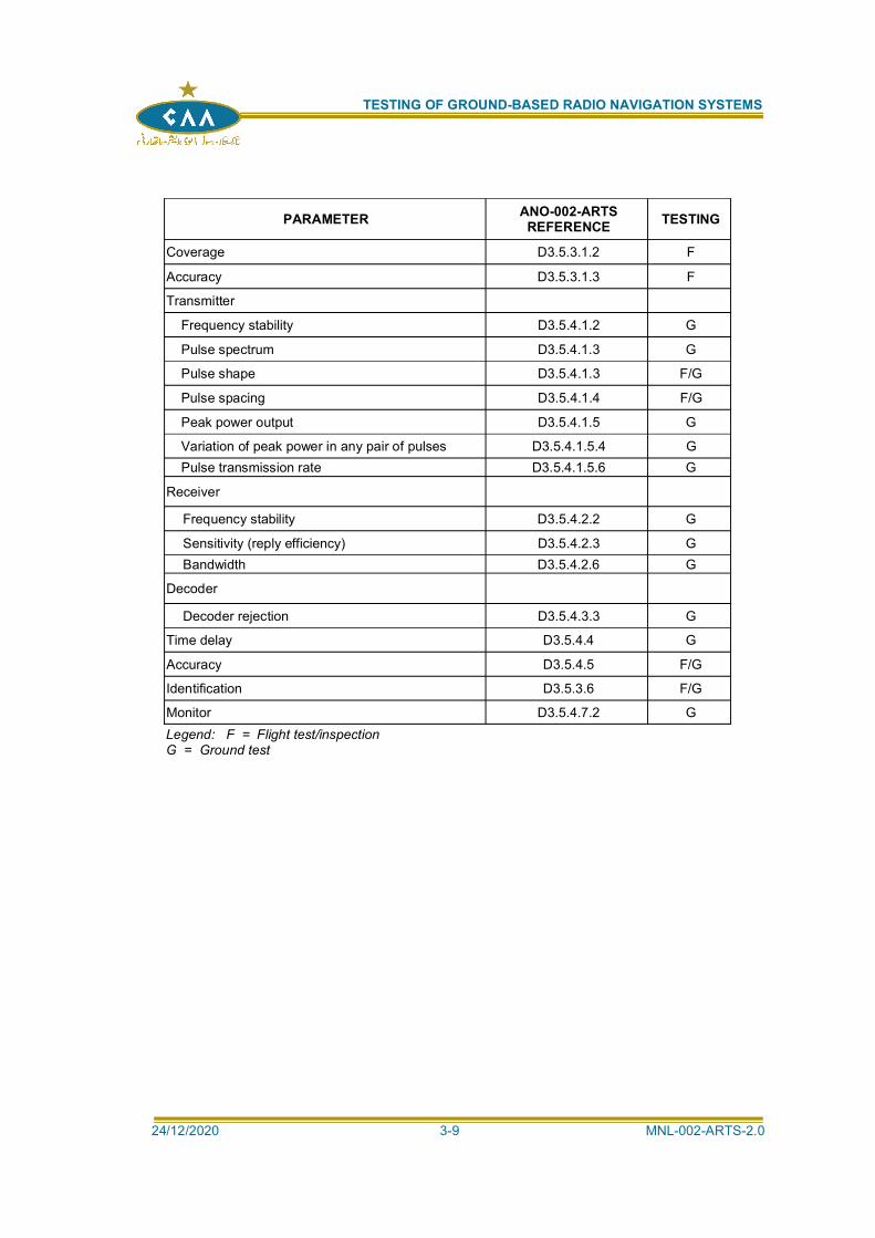
TESTING OF GROUND-BASED RADIO NAVIGATION SYSTEMS
24/12/2020 3-9 MNL-002-ARTS-2.0
PARAMETER ANO-002-ARTSREFERENCE TESTING
Coverage D3.5.3.1.2 F
Accuracy D3.5.3.1.3 F
Transmitter
Frequency stability D3.5.4.1.2 G
Pulse spectrum D3.5.4.1.3 G
Pulse shape D3.5.4.1.3 F/G
Pulse spacing D3.5.4.1.4 F/G
Peak power output D3.5.4.1.5 G
Variation of peak power in any pair of pulses D3.5.4.1.5.4 GPulse transmission rate D3.5.4.1.5.6 G
Receiver
Frequency stability D3.5.4.2.2 G
Sensitivity (reply efficiency) D3.5.4.2.3 GBandwidth D3.5.4.2.6 G
Decoder
Decoder rejection D3.5.4.3.3 G
Time delay D3.5.4.4 G
Accuracy D3.5.4.5 F/G
Identification D3.5.3.6 F/G
Monitor D3.5.4.7.2 GLegend: F = Flight test/inspectionG = Ground test
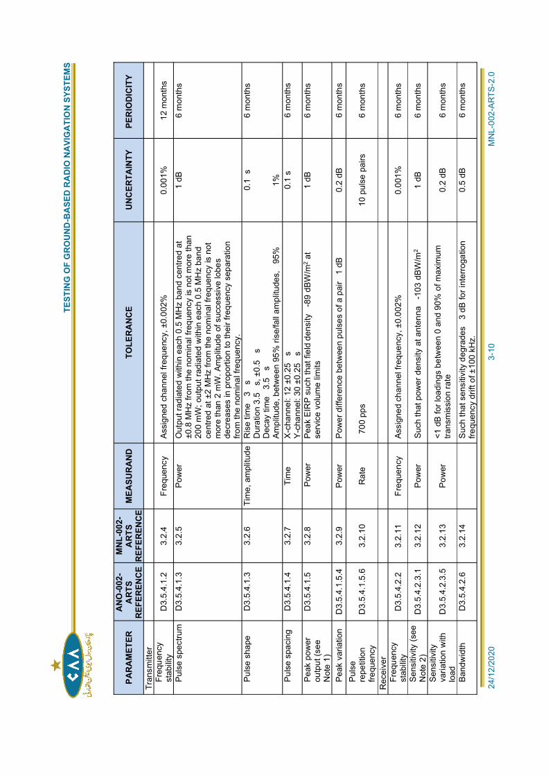
TES
TIN
G O
F G
RO
UN
D-B
ASE
D R
AD
IO N
AVI
GA
TIO
N S
YSTE
MS
2
4/12
/202
0
3
-10
M
NL-
002-
ARTS
-2.0
PARA
MET
ERA
NO
-002
-A
RTS
REF
EREN
CE
MN
L-00
2-A
RTS
REF
EREN
CE
MEA
SUR
AN
DTO
LER
AN
CE
UN
CER
TAIN
TYPE
RIO
DIC
ITY
Tran
smitt
erFr
eque
ncy
stab
ility
D3.
5.4.
1.2
3.
2.4
Fr
eque
ncy
As
sign
ed c
hann
el fr
eque
ncy,
±0.
002%
0.
001%
12
mon
ths
Puls
e sp
ectru
m
D3.
5.4.
1.3
3.
2.5
Po
wer
O
utpu
t rad
iate
d w
ithin
eac
h 0.
5 M
Hz
band
cen
tred
at±0
.8 M
Hz
from
the
nom
inal
freq
uenc
y is
not
mor
e th
an20
0 m
W; o
utpu
t rad
iate
d w
ithin
eac
h 0.
5 M
Hz
band
cent
red
at ±
2 M
Hz
from
the
nom
inal
freq
uenc
y is
not
mor
e th
an 2
mW
. Am
plitu
de o
f suc
cess
ive
lobe
sde
crea
ses
in p
ropo
rtion
to th
eir f
requ
ency
sep
arat
ion
from
the
nom
inal
freq
uenc
y.
1 dB
6
mon
ths
Puls
e sh
ape
D
3.5.
4.1.
3
3.2.
6
Tim
e, a
mpl
itude
R
ise
time
3s
Dur
atio
n 3.
5s,
±0.
5s
Dec
ay ti
me
3.5
sAm
plitu
de, b
etw
een
95%
rise
/fall
ampl
itude
s,95
%
0.1
s
1%
6 m
onth
s
Puls
e sp
acin
g
D3.
5.4.
1.4
3.
2.7
Ti
me
X
-cha
nnel
: 12
±0.2
5s
Y-c
hann
el: 3
0 ±0
.25
s0.
1 s
6 m
onth
s
Peak
pow
erou
tput
(see
Not
e 1)
D3.
5.4.
1.5
3.
2.8
P
ower
Pe
ak E
IRP
such
that
fiel
d de
nsity
-89
dBW
/m2 a
tse
rvic
e vo
lum
e lim
its1
dB
6 m
onth
s
Peak
var
iatio
n
D3.
5.4.
1.5.
4
3.2.
9
Pow
erP
ower
diff
eren
ce b
etw
een
puls
es o
f a p
air
1 dB
0.2
dB
6 m
onth
sPu
lse
repe
titio
nfre
quen
cyD
3.5.
4.1.
5.6
3.
2.10
R
ate
700
pps
10
pul
se p
airs
6
mon
ths
Rec
eive
rFr
eque
ncy
stab
ility
D3.
5.4.
2.2
3.
2.11
Fr
eque
ncy
As
sign
ed c
hann
el fr
eque
ncy,
±0.
002%
0.
001%
6
mon
ths
Sens
itivi
ty (s
eeN
ote
2)D
3.5.
4.2.
3.1
3.2.
12
Pow
er
Such
that
pow
er d
ensi
ty a
t ant
enna
-103
dBW
/m2
1 dB
6
mon
ths
Sens
itivi
tyva
riatio
n w
ithlo
adD
3.5.
4.2.
3.5
3.
2.13
Po
wer
<1 d
B fo
r loa
ding
s be
twee
n 0
and
90%
of m
axim
umtra
nsm
issi
on ra
te0.
2 dB
6
mon
ths
Band
wid
th
D3.
5.4.
2.6
3.
2.14
Suc
h th
at s
ensi
tivity
deg
rade
s3
dB fo
r int
erro
gatio
nfre
quen
cy d
rift o
f ±10
0 kH
z.0.
5 dB
6
mon
ths
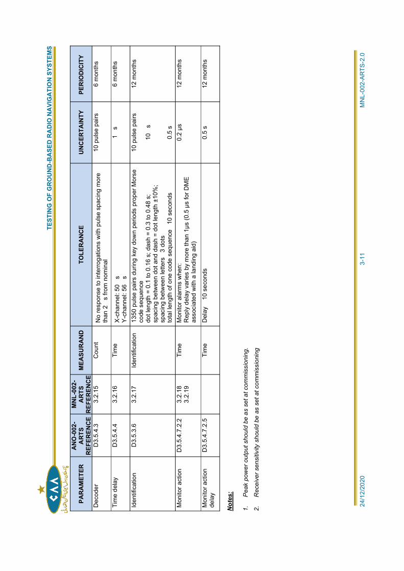
TES
TIN
G O
F G
RO
UN
D-B
ASE
D R
AD
IO N
AVI
GA
TIO
N S
YSTE
MS
2
4/12
/202
0
3
-11
M
NL-
002-
ARTS
-2.0
PARA
MET
ERA
NO
-002
-A
RTS
REF
EREN
CE
MN
L-00
2-A
RTS
REF
EREN
CE
MEA
SUR
AN
DTO
LER
AN
CE
UN
CER
TAIN
TYPE
RIO
DIC
ITY
Dec
oder
D
3.5.
4.3
3.
2.15
C
ount
No
resp
onse
to in
terro
gatio
ns w
ith p
ulse
spa
cing
mor
eth
an 2
s fro
m n
omin
al10
pul
se p
airs
6
mon
ths
Tim
e de
lay
D
3.5.
4.4
3.
2.16
Ti
me
X-c
hann
el: 5
0s
Y-c
hann
el: 5
6s
1s
6
mon
ths
Iden
tific
atio
n
D3.
5.3.
6
3.2.
17
Iden
tific
atio
n
1350
pul
se p
airs
dur
ing
key
dow
n pe
riods
pro
per M
orse
code
seq
uenc
edo
t len
gth
= 0.
1 to
0.1
6 s;
das
h =
0.3
to 0
.48
s;sp
acin
g be
twee
n do
t and
das
h =
dot l
engt
h ±1
0%;
spac
ing
betw
een
lette
rs3
dots
tota
l len
gth
of o
ne c
ode
sequ
ence
10 s
econ
ds
10 p
ulse
pai
rs
10s
0.5
s
12 m
onth
s
Mon
itor a
ctio
n D
3.5.
4.7.
2.2
3.2.
183.
2.19
Tim
e M
onito
r ala
rms
whe
n:R
eply
del
ay v
arie
s by
mor
e th
an 1
µs (0
.5 µ
s fo
r DM
Eas
soci
ated
with
a la
ndin
g ai
d)
0.2
µs
12 m
onth
s
Mon
itor a
ctio
nde
lay
D3.
5.4.
7.2.
5
Tim
e D
elay
10
seco
nds
0.5
s 12
mon
ths
Not
es:
1.
Pea
k po
wer
out
put s
houl
d be
as
set a
t com
mis
sion
ing.
2.
Rec
eive
r sen
sitiv
ity s
houl
d be
as
set a
t com
mis
sion
ing
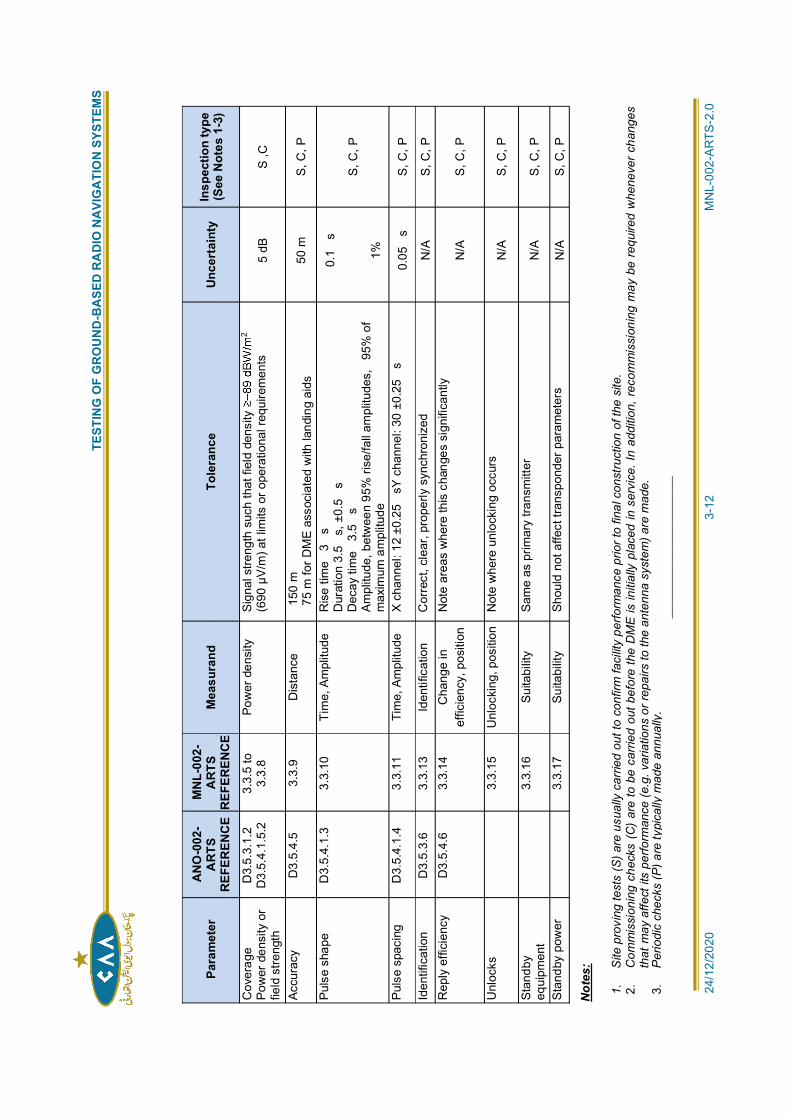
TES
TIN
G O
F G
RO
UN
D-B
ASE
D R
AD
IO N
AVI
GA
TIO
N S
YSTE
MS
2
4/12
/202
0
3
-12
M
NL-
002-
ARTS
-2.0
Para
met
erA
NO
-002
-A
RTS
REF
EREN
CE
MN
L-00
2-A
RTS
REF
EREN
CE
Mea
sura
ndTo
lera
nce
Unce
rtai
nty
Insp
ectio
n ty
pe(S
ee N
otes
1-3
)
Cov
erag
ePo
wer
den
sity
or
field
stre
ngth
D3.
5.3.
1.2
D3.
5.4.
1.5.
23.
3.5
to3.
3.8
Pow
er d
ensi
ty
Sign
al s
treng
th s
uch
that
fiel
d de
nsity
2
(690
µV/
m) a
t lim
its o
r ope
ratio
nal r
equi
rem
ents
5 dB
S
,C
Accu
racy
D
3.5.
4.5
3.3.
9 D
ista
nce
150
m75
m fo
r DM
E as
soci
ated
with
land
ing
aids
50 m
S,
C, P
Puls
e sh
ape
D3.
5.4.
1.3
3.3.
10
Tim
e, A
mpl
itude
R
ise
time
3s
Dur
atio
n 3.
5s,
±0.
5s
Dec
ay ti
me
3.5
sAm
plitu
de, b
etw
een
95%
rise
/fall
ampl
itude
s,95
% o
fm
axim
um a
mpl
itude
0.1
s
1%
S, C
, P
Puls
e sp
acin
g D
3.5.
4.1.
4 3.
3.11
Ti
me,
Am
plitu
de
X ch
anne
l: 12
±0.
25sY
cha
nnel
: 30
±0.2
5s
0.05
s S,
C, P
Iden
tific
atio
n D
3.5.
3.6
3.3.
13
Iden
tific
atio
n C
orre
ct, c
lear
, pro
perly
syn
chro
nize
dN
/A
S, C
, PR
eply
effi
cien
cy
D3.
5.4.
6 3.
3.14
C
hang
e in
effic
ienc
y, p
ositi
onN
ote
area
s w
here
this
cha
nges
sig
nific
antly
N/A
S,
C, P
Unl
ocks
3.3.
15
Unl
ocki
ng, p
ositi
on
Not
e w
here
unl
ocki
ng o
ccur
sN
/A
S, C
, P
Stan
dby
equi
pmen
t
3.3.
16
Suita
bilit
y Sa
me
as p
rimar
y tra
nsm
itter
N/A
S,
C, P
Stan
dby
pow
er
3.
3.17
Su
itabi
lity
Shou
ld n
ot a
ffect
tran
spon
der p
aram
eter
sN
/A
S, C
, P
Not
es:
1.
Site
pro
ving
test
s (S
) are
usu
ally
car
ried
out t
o co
nfirm
faci
lity
perfo
rman
ce p
rior t
o fin
al c
onst
ruct
ion
of th
e si
te.
2.C
omm
issi
onin
g ch
ecks
(C
) ar
e to
be
carri
ed o
ut b
efor
e th
e D
ME
is in
itial
ly p
lace
d in
ser
vice
. In
addi
tion,
rec
omm
issi
onin
g m
ay b
e re
quire
d w
hene
ver c
hang
esth
at m
ay a
ffect
its
perfo
rman
ce (e
.g. v
aria
tions
or r
epai
rs to
the
ante
nna
syst
em) a
re m
ade.
3.P
erio
dic
chec
ks(P
) are
typi
cally
mad
e an
nual
ly.
____
____
____
____
____
____
__
TESTING OF GROUND-BASED RADIO NAVIGATION SYSTEMS
24/12/2020 4-1 MNL-002-ARTS-2.0
Chapter 4
INSTRUMENT LANDING SYSTEM (ILS)
4.1 INTRODUCTION:
GENERAL:
4.1.1 The purpose of this chapter is to provide guidance on flight and ground inspectionrequirements applicable to the standard instrument landing system (ILS), as specified inANO-002-ARTS, D2.2 and D3.1.
SYSTEM DESCRIPTION
4.1.2 The ILS provides precision guidance to an aircraft during the final stages of the approach.The signals can either be interpreted by the pilot from the instruments or be inputdirectly into the autopilot and flight management system. ILS facility performance isdivided into three categories depending on the reliability, integrity and quality of guidance,with facility performance Category III having the strictest requirements. An ILS comprisesthe following elements:
a) the localizer, operating in the frequency band
b) the glide path, operating in the frequency band from 328 to 336 MHz, providingelevation guidance to a typical maximum range of 18.5 km (10 NM) from the runwaythreshold; and
c) an appropriate means to enable glide path verification checks.
4.1.2.1 Distance to threshold information to enable glide path (altitude) verificationchecks is normally provided by:
a) VHF marker beacons operating on the frequency of 75 MHz, providing positioninformation at specific distances from the runway threshold; or
b) distance measuring equipment (DME) operating in the frequency band from 960to 1215 MHz on channels paired with the localizer, providing continuous distance torunway information.
If other standard radio navigation aids are used for this function, appropriate ground andflight test requirements must also be determined.
GROUND AND FLIGHT TESTING:
4.1.3 Adequate monitoring, ground testing and maintenance on a routine and continuing basisshould be the normal means of ensuring that the ILS signal-in-space performs within thespecified tolerances and that the operational integrity and serviceability of the ILS facility ismaintained. Flight testing is required to confirm the correctness of the setting of essentialsignal-in-space parameters, determine the operational safety and acceptability of the ILSinstallation and periodically correlate signal patterns observed in flight and from theground. Both types of testing provide awareness of long-term changes in the operationalenvironment caused by effects such as multipath from on-airport construction activities. Inpractice, it has been found that certain ILS performance parameters can be determinedmore accurately and with greater reliability by ground measurements than through flightinspection. If the ground and flight measurements show different results, the reason forthe divergence should be investigated.
4.1.4 Reserved.
TESTING OF GROUND-BASED RADIO NAVIGATION SYSTEMS
24/12/2020 4-2 MNL-002-ARTS-2.0
TESTING REQUIREMENTS:
4.1.5 A summary of testing requirements for ILS localizer, glide path and markers is given inTables I-4-1, I-4-2 and I-4-3. Where measurement uncertainties are given, they are thetwo-sigma or 95 per cent confidence level values.
SPECIAL MEASURES PREVENTING THE OPERATIONAL USE OF TEST SIGNALS:
4.1.6 Some ground and flight test procedures, as described in this chapter, involve misleadingguidance signals being temporarily radiated by ILS or the executive monitoring function ofthe equipment being inhibited. Such signals, particularly those radiated for phasing and
ILS coverage and with no flag or alarm indication in the cockpit. The operational use ofthese signals for approach guidance can therefore result in misleading indications to theflight crew and has the potential to cause a controlled flight into terrain (CFIT) accident.
4.1.7 Accordingly, the appropriate PCAA authority (or the organization authorized by the PCAA)should develop measures to ensure that ILS test signals will not be used during normalflight operations when these signals are being radiated or the executive monitoringfunction of the facility is inhibited for testing/maintenance purposes. Coordination of testingprocedures with ATC and the timely promulgation and distribution of relevant informationby a NOTAM before the procedures commence are of paramount importance.
4.1.8 It is highly desirable to eliminate the possibility of any operational use to be made ofthe ILS guidance during the testing by administratively (e.g. by a NOTAM) removing thelocalizer and the glide path from service simultaneously. If this is not feasible foroperational reasons, a deferral of testing should be considered. However, in case thelocalizer needs to remain in service while the glide path undergoes testing and the testingcannot be delayed, sufficient measures should be implemented to ensure that users areaware of the potential for false indications from the glide path facility.
4.1.9 In all circumstances, the basic protective measures should include as a minimum:
a) NOTAM phraseology that is specific about the possibility of false indications to theflight crew from the radiated test signals and clearly prohibits their use (suggested
b) confirmation by maintenance personnel that such a NOTAM has been issued bythe Aeronautical Information Service before the testing procedures begin;
c) prior to beginning the tests, suspension or alteration to an unusual tone/sequence ofthe transmission of the unique Morse Code facility identification on the localizer, if thelocalizer should radiate solely for testing purposes; and
d) a requirement that ATC advise, by the automatic terminal information service (ATIS)and/or by a voice advisory, each pilot on an approach to the affected runway,emphasizing the possibility of false indications.
4.1.10 Additional protective measures may be appropriate, especially during phasing andmodulation balance conditions for the localizer or the glide path (4.2.15, 4.2.37, 4.3.14,4.3.39, 4.3.62 and 4.3.63 refer). Accordingly, when the phasing and modulation balancetests are being performed, the following options may be exercised:
a) when the tests are being performed on the localizer, remove the glide path fromservice by turning the signals off (to provide a glide path flag indication to the pilot);
b) when the tests are being performed on the glide path, remove the localizer fromservice by turning the signals off (to provide a localizer flag indication to the pilot);and/or
TESTING OF GROUND-BASED RADIO NAVIGATION SYSTEMS
24/12/2020 4-3 MNL-002-ARTS-2.0
If option b) is exercised, the ATC advisories indicated in 4.1.9 d)above become redundant.
c) minimize the time radiating in a ground phasing condition by performing the testingwith two or more technicians and radio communications.
4.1.11 In addition, it is essential to ensure that protective measures (in addition to thecoordination and promulgation processes) are put in place to guard against single pointsof failure. One highly desirable measure is the installation of remote ILS status-indicatingequipment such that it is visible to the air traffic controller issuing approach clearances.
ANALYSIS CONCERNING HARMFUL INTERFERENCE CAUSED BY OPPOSITE RUNWAYLOCALIZER TRANSMISSION:
4.1.12 At those locations where two ILS facilities serve the opposite ends of a single runwaywithout a means to avoid simultaneous transmission by both localizers (e.g. interlock), it isnecessary to verify the absence of operationally harmful interference when both localizersare transmitting.
4.1.13 This verification may be done through flight test with both localizers transmitting or bygeometry analysis. The second option consists in checking that the overflight of theopposite localizer (the area of harmful interference) is beyond the applicable limit at whichthe course structure requirements should be met.
4.2 GROUND TESTING:
GENERAL:
4.2.1 The primary purposes of ground testing are to ensure that the ILS radiates a signalmeeting the requirements of Annex 10 and to confirm correct monitor operation. Since ILSequipment varies greatly, it is not possible to define detailed tests applicable to all types.Therefore, only a high-level description of the tests are provided below, and
procedures of specific equipment. The periodicity shown for ground tests may be extendedbased on appropriate considerations as discussed in Chapter 1, such as the use ofcontinuous monitoring techniques or good correlation between ground and airbornemeasurements of the same parameters.
GROUND PERFORMANCE PARAMETERS:
4.2.2 Ground test requirements for localizers, glide paths, and ILS marker beacons are listedin Tables I-4-4, I-4-5, and I-4-6. Ground test requirements for DME associated with ILSare listed in Table I-3-2.
GROUND TEST PROCEDURES:
GENERAL:
4.2.3 The procedures for conducting the ground testing of the parameters listed inTables I-4-4, I-4-5 and I-4-6 are intended to provide basic guidance in themethod of measuring the various parameters. These procedures should not beconstrued as the only means of accomplishing the intended purpose; particularair navigation service providers (ANSPs) might find modified or new methodswhich better suit their equipment or local situation.
INDEPENDENCE OF GROUND MEASUREMENTS AND MONITOREQUIPMENT:
4.2.4 In most cases, these measurements will be made using equipmentother than the monitors that are a part of the normal installation. This isbecause a primary value of ground tests is to confirm overall monitorperformance, and it is therefore desirable to make corroborative checks
TESTING OF GROUND-BASED RADIO NAVIGATION SYSTEMS
24/12/2020 4-4 MNL-002-ARTS-2.0
on monitor indications using independent equipment. Significantdifferences in the correlation between the check measurements andmonitor indications should always be investigated and resolved.
CORRELATION BETWEEN FIELD AND MONITOR INDICATIONS:
4.2.5 When checks are made on the monitor indications by means ofportable test equipment, the following effects should be taken intoaccount:
a) Aperture effect: The extent of the near-field is a function of theaperture of the radiating antenna system.
1) Localizer: For apertures up to 30 m (100 ft), negligible errordue to the near-field effect will be introduced ifmeasurements are made at points beyond a ten-aperture(twenty apertures preferred) distance from the localizerantenna. For larger aperture antennas, a minimum distanceof twenty apertures is recommended to obtain readings thatare more accurate.
2) Glide path: The equipment is normally adjusted so that thesignal phase relationships existing on the runway centre lineat threshold or beyond are correct. For this reason, theILS reference datum represents a good position for glidepath measurement. If possible, positions on the extendedrunway centre line should be used. However, any location issuitable if a good correlation between the measured and far-field conditions is obtained.
b) Ground constants: In the near-field region the measurementaccuracy may be adversely affected by changes in groundconstants. Satisfactory drainage and soil stabilization would helpto achieve stability.
c) Diffracted and reflected energy: The alignment and displacementsensitivity of the localizer and the glide path may be affected bythe presence of diffracted and reflected energy. This should betaken into account when such characteristics are determined forthe first time
CORRELATION BETWEEN GROUND AND FLIGHT TESTS:
4.2.6 Whenever possible, the correlation between simultaneous or nearlysimultaneous ground and airborne measurement results on the sameor related parameters should be analysed. Good correlation will usuallyresult in increased confidence in both measurements, and whenrigorously applied, may be the basis for extending maintenance or testintervals, as discussed in Chapter 1.
4.2.7 Typically, the necessary conditions for correlation of measurementresults include the availability of proper ground maintenance testequipment, traceable calibration programmes for ground and airbornetest equipment, availability of commissioning and recent test reports,and similar level of understanding between ground and airbornepersonnel on the meaning and value of measurement correlation. Iffeasible, a meeting between ground maintenance and airborne testpersonnel before the measurements is desirable, particularly ifdissimilar test generators and receivers are used. If measurements donot agree within predefined tolerances and cannot be resolved, actionssuch as tightening monitor alarm points, declassifying the facility, orremoving it from service should be considered.
TESTING OF GROUND-BASED RADIO NAVIGATION SYSTEMS
24/12/2020 4-5 MNL-002-ARTS-2.0
LOCALIZER:
LOCALIZER COURSE ALIGNMENT
4.2.8 The measurement of localizer course alignment should be carried outin the far-field region of the localizer. There are several alternativemethods that may be employed. One method, which is widely used,employs portable field test equipment which is located at pre-surveyedpoints on the runway centre line or on the extended centre line. Thecourse structure at the position selected for these measurementsshould be stable and free of multipath distortions. By using this testequipment, the position of the course line relative to the runway centreline may be determined. This method enables single-pointmeasurement of the course line to be obtained and is considered to beadequate for Category I and II facilities.
4.2.9 For Category III facilities, it may be desirable to employ a measurementprocedure which is able to display the mean value of the course lineover a significant portion of the runway. This test equipment may takethe form of an ILS precision receiver, antenna and recorder mounted ina vehicle. An antenna height that approximates the height of an aircraftantenna on roll-out should be used, e.g. 3 to 8 m (10 to 26 ft).Typically, low-pass filtering of the raw cross- pointer signal isnecessary to approximate the results obtained with an aircraft. Thetotal time-constant of the receiver and recorder difference in depth ofmodulation (DDM) circuits for the vehicle measurements should bereferenced to an aircraft speed of 195 km/hr (105 kt), for which theconstant is approximately 0.5 second (refer to Attachment C toAnnex 10, Volume I, 2.1.6 for specific filter guidance). The testvehicle is driven along the runway centre line and a recording of thecourse structure obtained over the region from the runway threshold toILS Point E. From this recording the alignment for each zone forapplication of structure tolerances may be determined as the averagecourse position between runway threshold and Point D, and separatelybetween Point D and Point E. To analyse the post-filtering lowfrequency spectral components, the guidance found in Attachment Cto Annex 10, Volume I, 2.1.3 and 2.1.5, should be used, with thestructure tolerances referenced to the average course position ineach zone. For alignment, it is preferable to use a directional antenna.For course structure, it is preferable to use an antenna with limiteddirectivity, which is similar to the performance of an aircraft antenna.
DISPLACEMENT SENSITIVITY
4.2.10 Displacement sensitivity of the localizer is measured with testequipment located at surveyed positions in the far-field where thecourse structure is known and stable. These test positions are typicallyon opposite sides of the runway centre line as close as possible to theedge of the half-course sector and ideally at the same distance to thearray. The test equipment reading obtained at each position isrecorded, and the displacement sensitivity is calculated in units ofDDM/metre as the sum of the absolute value of the two DDM values,divided by the distance between the two surveyed points. If the testpositions are not located on a line perpendicular to the runwaycentre line at the ILS reference datum, then the measureddisplacement needs to be scaled as shown in Figure I-4-1
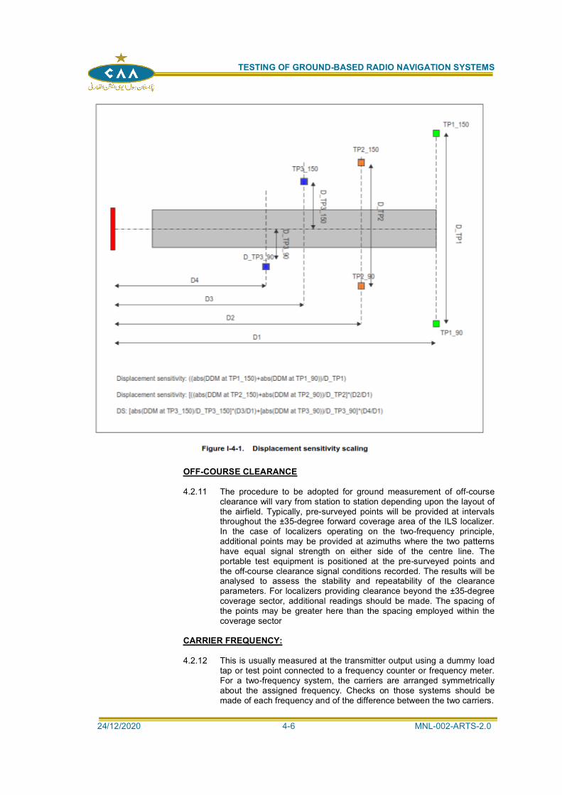
TESTING OF GROUND-BASED RADIO NAVIGATION SYSTEMS
24/12/2020 4-6 MNL-002-ARTS-2.0
OFF-COURSE CLEARANCE
4.2.11 The procedure to be adopted for ground measurement of off-courseclearance will vary from station to station depending upon the layout ofthe airfield. Typically, pre-surveyed points will be provided at intervalsthroughout the ±35-degree forward coverage area of the ILS localizer.In the case of localizers operating on the two-frequency principle,additional points may be provided at azimuths where the two patternshave equal signal strength on either side of the centre line. Theportable test equipment is positioned at the pre-surveyed points andthe off-course clearance signal conditions recorded. The results will beanalysed to assess the stability and repeatability of the clearanceparameters. For localizers providing clearance beyond the ±35-degreecoverage sector, additional readings should be made. The spacing ofthe points may be greater here than the spacing employed within thecoverage sector
CARRIER FREQUENCY:
4.2.12 This is usually measured at the transmitter output using a dummy loadtap or test point connected to a frequency counter or frequency meter.For a two-frequency system, the carriers are arranged symmetricallyabout the assigned frequency. Checks on those systems should bemade of each frequency and of the difference between the two carriers.
TESTING OF GROUND-BASED RADIO NAVIGATION SYSTEMS
24/12/2020 4-7 MNL-002-ARTS-2.0
OUTPUT POWER:
4.2.13 The power into the antenna system may be measured using awattmeter, preferably of the through-line type that is capable ofindicating direct and reflected power. During installation, it may beconvenient to relate this power measurement to field strength at therunway threshold. This can be done by measuring field strength on thecourse line at the threshold (at a height of 4 m (13 ft) for Category IIand III) and at the same time recording the power into the antennasystem. Subsequently, the power should be reduced by 3 dB and theresulting threshold field strength again recorded.
TONE FREQUENCY:
4.2.14 Measurement of tone frequency is made by use of a frequency counteror other suitable type of basic test instrument. Instructions on themethod to be employed can be found in the equipment handbook. Incases where signal tones are generated from very stable sources, thismeasurement of tone frequency may be performed less frequently.
MODULATION DEPTH (90/150 HZ):
4.2.15 Modulation depth is probably one of the most difficult quantities tomeasure to the required accuracy, and only high precision instrumentsshould be used. The technique used to measure the modulationdepths should preferably be one which analyses the waveform withboth modulating tones present. If the measurement can only be madewith one tone present, care should be taken to ensure that:
a) the individual tone amplitude is not affected by the removal or theaddition of the other tone;
b) the modulator remains linear with both tones present; and
c) the harmonic content of the tone is as low as possible.
MODULATION DEPTH (1020 HZ):
4.2.16 Measurement of the modulation depth of the 1 020 Hz identificationtone can be carried out by wave analyser comparison between themodulation depth of the 90 Hz tone and the 1 020 Hz tone or byportable test equipment, which can measure it directly. The waveanalyser is tuned to 90 Hz and the scale amplitude is noted. The waveanalyser is then tuned to 1 020 Hz and the modulation depth of the 1020 Hz is adjusted to the appropriate proportion of the 90 Hz reading.
HARMONIC CONTENT OF THE 90 AND 150 HZ TONES:
4.2.17 This is measured at the transmitter cabinet using a detector feeding awave analyser from which a value is obtained on a root mean square(RMS) calculation basis. For future checks a distortion factor metermay be used, however, this can indicate a higher value of distortionthan that contributed by the harmonics themselves
90/150 HZ PHASING:
4.2.18 Measurement of the relative phase between the 90 and 150 Hztones can most conveniently be made using one of the commerciallyavailable instruments specifically designed for this purpose. Where twofrequency carrier systems are used, the relative phase of the 90/150Hz tones should be checked separately for each system. An additionalcheck of the relative phase of the two 90 Hz and two 150 Hz tonesshould then be carried out.
TESTING OF GROUND-BASED RADIO NAVIGATION SYSTEMS
24/12/2020 4-8 MNL-002-ARTS-2.0
4.2.19 When such equipment is not available, a check that the 90/150 Hzphase is within the required tolerance can be made on the combinedwaveform using the following oscilloscope technique:
a) with the modulation balance adjusted for the zero DDM tonecondition, adjust the oscilloscope time-base to give a lockeddisplay of the combined tones, such that four adjacent positive
larger, equal or nearly equal amplitude, and two of a smaller,equal or nearly equal amplitude;
b) measure, as accurately as possible, the amplitudes of the twolargest peaks; and
c) divide the lesser amplitude by the larger amplitude (for aratio less than or equal to unity). The 90/150 Hz phasing iswithin tolerance if the ratio is greater than 0.903 for Category Iand II localizers or greater than 0.951 for Category III localizers.(Note that any distortion of the tones will degrade the accuracy ofthe result.)
4.2.20 To measure the phase between the 90 Hz or 150 Hz tones of thetwo transmitters of a two-frequency system, connect the modulationsignal from each transmitter to a separate oscilloscope channel.Configure the oscilloscope to display both channels simultaneously,such that the waveform for the transmitter that leads the other in timecrosses the zero amplitude line at a convenient reference point onthe horizontal axis. Measure the difference in time between the twowaveforms at the point at which they each cross the zero amplitudeline, and convert that time to degrees-of-phase for comparison with thetolerance.
ILS CARRIER FREQUENCY AND PHASE MODULATION:
4.2.21 In addition to the desired 90 Hz and 150 Hz AM modulation of the ILSRF carriers, undesired frequency modulation (FM) and/or phasemodulation (PM) may exist. This undesired modulation may causecentring errors in ILS receivers due to slope detection by a ripple in theintermediate frequency (IF) filter pass-band.
4.2.22 One method of measuring this undesired FM and/or PM is to use acommercial modulation meter. The RF input to the modulation metermay be taken from any convenient RF carrier sampling point on the ILStransmitter. The modulation meter and its connecting cables should bewell screened, since any unwanted pickup of sideband radiation maybe interpreted as FM or PM. It is preferable to use a sampling pointwith a high signal level and place an attenuator directly on the inputsocket of the modulation meter.
4.2.23 The audio filters used in the modulation meter should have abandwidth at least as wide as the tone filters used in ILS receivers.This is necessary to ensure that undesired FM and/or AM onfrequencies other than 90 Hz and 150 Hz, which could affect an ILSreceiver, will be measured by the modulation meter. For standardizingthese measurements, the recommended filter characteristics are givenin the table below
TESTING OF GROUND-BASED RADIO NAVIGATION SYSTEMS
24/12/2020 4-9 MNL-002-ARTS-2.0
Recommended filter characteristics for FM/PM measurement
Frequency(Hz)
90 Hz band-pass filterattenuation dB
150 Hz band-pass filterattenuation dB
45 10 16
85 0.5 (no spec.)
90 0 14
95 0.5 (no spec.)
142 (no spec.) 0.5
150 14 0
158 (no spec.) 0.5
300 16 10
MONITORING SYSTEM OPERATION:
4.2.24 This test is essentially a check on the overall executive operation of themonitor systems. The total time periods specified are never-to-be-exceeded limits and are intended to protect aircraft in the final stages ofapproach against prolonged or repeated periods of localizer guidanceoutside the monitor limits. For this reason they include not only theinitial period of outside tolerance operation but also the total of any orall periods of out-of-tolerance radiation, which might occur duringaction-to-restore service, for example, in the course of consecutivemonitor functioning and consequent change-over(s) to localizerequipment(s) or elements thereof. The intention is that no guidanceoutside the monitor limits be radiated after the time periods given, andthat no further attempt be made to restore service until a period in theorder of 20 seconds has elapsed.
MONITOR COURSE ALIGNMENT ALARM
4.2.25 The purpose of this check is to ensure that the monitor executive actionoccurs for a course alignment shift of the distances specified in Table I-4-4 (90 and 150 Hz side). One of the following methods may be used:
a) The alignment of the ILS localizer course line may be offset bythe operation of a control in either the transmitter cabinet orantenna system, as may be appropriate to the particularinstallation under examination. At the point where the monitorsystem indicates that an alarm condition has been reached,measurement of the resulting far-field course alignment should beverified to be in accordance with Table I-4-4. This test should,where possible, be carried out at the time of the course alignmentcheck.
b) The measurement of course alignment alarm may be carried outby the application of a precision ILS signal generator to themonitor input.
MONITOR DISPLACEMENT SENSITIVITY ALARM:
4.2.26 The purpose of this check is to ensure that the monitor displacementsensitivity alarm action occurs for changes in displacement sensitivityspecified in Table I-4-4. One of the following methods may be used:
TESTING OF GROUND-BASED RADIO NAVIGATION SYSTEMS
24/12/2020 4-10 MNL-002-ARTS-2.0
a) The ILS localizer course width may be adjusted by operating asuitable control (width control) until the monitor system indicatesthat a wide alarm condition has been reached. When an alarm isindicated, the displacement sensitivity in the far-field should beverified to be in accordance with Table I-4-4. Following thismeasurement, the width control setting needed to initiate thenarrow alarm is selected and displacement sensitivity againmeasured using the ILS test method as described above.
b) The measurement of displacement sensitivity alarm may becarried out by the application of a precision ILS signal generatorto the monitor input.
MONITOR POWER REDUCTION ALARM
4.2.27 The purpose of this check is to ensure that the monitor power reductionalarm action occurs for the change in power specified in Table I-4-4.The ILS localizer output power is reduced by operation of a suitablecontrol (transmitter output power) until the monitor system reaches analarm condition. At this point, the output power should be measured. Acalibrated signal generator input into the monitor can also be used forthis measurement.
FAR-FIELD MONITOR:
4.2.28 A far-field monitor usually consists of a number of antennas andreceivers located at the middle marker-to-threshold region to providecontinuous measurement of localizer parameters for ground inspectionpurposes. It may also function as a monitor of course position, andoptionally, of course sensitivity. The far-field monitor indications arenormally readily available to the ground maintenance staff to facilitatethe assessment of localizer performance. A continuous logging ordisplay of localizer parameters is preferred. In the interpretation of theresults, it should be remembered that the indications will be disturbedby aircraft overflying the localizer and far-field monitor as well as othervehicle movements at the airport. Periodically, the correlation betweenthe far-field monitor and the localizer signal-in-space should beestablished.
GLIDE PATH:
PATH ANGLE:
4.2.29 The recommended means of measurement of a glide path angle ( ) isby flight test. However, it may be measured on the ground either atthe field monitoring location or at a distance of at least 400 m (1 200ft) from the transmitting antenna, preferably on the extended centreline of the runway.
4.2.30 The measurement location used will depend on the type of glide path,its monitoring system and the local site conditions. Where there is nofield monitoring, or where the signal at the monitor location may beaffected by local conditions, e.g. accumulation of snow, change inground characteristics, etc., then the angle measurements should bemade at least 300 m (1 000 ft) in front of the glide path as suggestedabove. In any case, it is preferable at the time of commissioning tomeasure the glide path parameters at this location for future reference.
4.2.31 When measurements are made beyond the normal monitoring location,a portable ILS ground checking installation should be usedcomprising a vehicle or trailer suitably equipped for measuring glidepath signals. The facilities should include lifting gear to enable the
TESTING OF GROUND-BASED RADIO NAVIGATION SYSTEMS
24/12/2020 4-11 MNL-002-ARTS-2.0
antenna of the test receiver to be raised to a height of at least 22 m(70 ft). Means should be provided for determining the height of thetest antenna above ground level to an accuracy of ±5 cm (±2 inches).The figures obtained as a result of this test may differ from thosederived from an in-flight measurement, by an amount which willdepend on the siting of the test equipment relative to the transmitterantenna and the type of transmitting equipment used.
DISPLACEMENT SENSITIVITY:
4.2.32 The recommended means of measurement of displacement sensitivityis by flight test. However, ground measurement of this parametershould be made using the method described for the glide path angle,but test antenna heights should be determined additionally at which0.0875 DDM occurs below and above the glide path. The heightsobtained will enable figures to be derived for the representativestandard upper and lower half-sector displacement sensitivities at theposition at which the checks are made.
CLEARANCE BELOW PATH:
4.2.33 Ground measurement of below path clearance is not normallyrequired for null reference systems. For other systems themeasurement may be made as described for the glide path angle. Testantenna heights should be determined and DDM values recorded toenable a curve to be plotted showing DDM between 0.3 and the lowerhalf- sector. From the curve of DDM versus angle plotted, therepresentative standard clearance below path performance may beobtained. A value of 0.22 DDM should be achieved at an angle not lessthan 0.3 above the horizontal. However, if it is achieved at an angleabove 0.45 , the DDM value should not be less than 0.22 at least downto 0.45 .
CARRIER FREQUENCY:
4.2.34 This test is the same as for the localizer (4.2.12).
OUTPUT POWER:
4.2.35 This test is the same as for the localizer (4.2.13), except that thethreshold power measurements should be made at the zero DDMheight.
TONE FREQUENCY (90/150 HZ):
4.2.36 This test is the same as for the localizer (4.2.14).
MODULATION DEPTH (90/150 Hz):
4.2.37 This test is the same as for the localizer (4.2.15).
HARMONIC CONTENT OF THE 90 AND 150 HZ TONE:
4.2.38 This test is the same as for the localizer (4.2.17).
90/150 HZ PHASING:
4.2.39 This test is the same as for the localizer (4.2.18).
ILS CARRIER FREQUENCY AND PHASE MODULATION:
4.2.40 This test is the same as for the localizer (4.2.21).
TESTING OF GROUND-BASED RADIO NAVIGATION SYSTEMS
24/12/2020 4-12 MNL-002-ARTS-2.0
MONITOR SYSTEM OPERATION:
4.2.41 This test is the same as for the localizer (4.2.24).
MONITOR ANGLE ALARMS:
4.2.42 The purpose of this check is to ensure that the monitor executive actionoccurs for a change in glide path angle specified in Table I-4-5 (90 and150 Hz side). Some facilities may require monitor executive limits to beadjusted to closer limits than those specified in the table because ofoperational requirements. One of the following methods may be used:
a) The alignment of the ILS glide path may be offset by the operationof a control in either the transmitter cabinet or antenna system, asmay be appropriate, to the particular installation underexamination. At the point where the monitor system indicates thatan alarm condition has been reached, measurement of theresulting far-field path alignment should be verified to be inaccordance with Table I-4-5. This test should, where possible, becarried out at the time of the path alignment check.
b) The measurement of the path alignment alarm may be carried outby the application of a precision ILS signal generator to themonitor input.
MONITOR DISPLACEMENT SENSITIVITY ALARM:
4.2.43 The purpose of this check is to ensure that the monitor displacementsensitivity alarm action occurs for changes in displacement sensitivityspecified in Table I-4-5. One of the following methods may be used:
a) The ILS glide path width is adjusted by operating a suitablecontrol (width control) until the monitor system indicates that awide or narrow alarm condition has been reached. When an alarmis indicated, the displacement sensitivity in the far-field should beverified to be in accordance with Table I-4-5. Following thismeasurement, the width control setting needed to initiate thealternate alarm is selected and displacement sensitivity againmeasured using the test method as described above.
b) The measurement of displacement sensitivity alarm may becarried out by the application of a precision ILS signal generatorto the monitor input.
MONITOR POWER REDUCTION ALARM:
4.2.44 This test is the same as for the localizer (4.2.27).
MARKER BEACONS:
CARRIER FREQUENCY:
4.2.45 The carrier frequency should be checked using an accurate frequencycounter to ensure that it is within tolerance. Reference should be madeto the instructions supplied with the frequency counter which will givethe detailed procedures for its use.
RF OUTPUT POWER:
4.2.46 Since the power output of the beacon transmitter directly affects thecoverage obtained, it is important to keep the power output as close aspossible to the value recorded at the time of commissioning. On most
TESTING OF GROUND-BASED RADIO NAVIGATION SYSTEMS
24/12/2020 4-13 MNL-002-ARTS-2.0
equipment, a meter is provided to read the reference output voltage (orsome other measure of output power) of the transmitter. This indicationmay be checked by using an independent power output meter. Thevoltage standing wave radio (VSWR) should also be checked using theformula below based on measurements of forward and reflectedpowers. Any change in the output level or VSWR from its initial value atcommissioning could be due to a change in the power delivered fromthe transmitter and/or a change in the characteristics of the antennasystem. Changes should therefore be investigated, as the performanceof the beacon will be affected
MODULATION DEPTH:
4.2.47 The modulation depth can be measured using a modulation meter (it maybe built into the equipment) or by an oscilloscope. Using an oscilloscope,the modulated signal from the beacon is displayed (usually by directconnection to the deflection plates), and the modulation percentageobtained by measuring the maximum and minimum of the modulationenvelope. If Amax and Amin are the maximum and the minimum of theenvelope respectively, then
MODULATION TONE FREQUENCY:
4.2.48 This test is the same as for the localizer (4.2.14).
HARMONIC CONTENT OF MODULATING TONE:
4.2.49 This test is the same as for the localizer (4.2.17).
KEYING:
4.2.50 An audible indication of keying will usually be available from a test pointon the equipment or monitor. The keying can therefore be checkedaudibly for clear, correct identification. A more exact check can bemade by using a suitable oscilloscope.
MONITOR SYSTEM
4.2.51 The monitor system should be checked to ensure it will detecterroneous transmissions from the marker beacon. Some monitorsinclude switching functions that permit out-of-tolerance conditions to be
instructions.
CHARTS AND REPORTS:
GENERAL:
4.2.52 The objective of the collection and analysis of data on the various ILS parametermeasurements is to build up a record-of-performance of the equipment in orderto determine whether its performance objectives are being achieved. In addition,these records can show performance trends and long-term drifts which, in somecases, will enable preventive maintenance to be carried out prior to anunscheduled service outage. Although the methods used by differentauthorities to carry out ground inspections and the analysis of results will vary,there are certain general principles to be observed and precautions to be taken.
TESTING OF GROUND-BASED RADIO NAVIGATION SYSTEMS
24/12/2020 4-14 MNL-002-ARTS-2.0
EQUIPMENT FAILURE ANALYSIS:
4.2.53 It is important that records be kept and an analysis be made on equipmentfailures and outage times to determine if the reliability objectives appropriate tothe category of operation are being achieved in service. Details of the type ofdata to be collected and the method of analysis can be found in Attachment F toANO-002-ARTS.
PERFORMANCE ANALYSIS:
GENERAL:
4.2.54 In order that the performance determined from measurements over along period will be statistically valid, unnecessary adjustments shouldbe minimized. The equipment settings should not be modified if theparameters listed in Tables I-4-4 through I-4-6 are within 50 per cent ofthe given tolerance.
ANALYSIS OF ALIGNMENT AND SENSITIVITY MEASUREMENT:
4.2.55 The localizer and glide path alignment and displacement sensitivitymeasurements should be analysed to determine the mean anddistribution of these parameters. Online data-processing systems maybe installed, which will automatically collect and analyse theseparameters and produce the performance statistics. The radiatingequipment should then be adjusted so that, on a long-term basis, themean of the parameter corresponds to the proper nominal value. Thedistribution should be analysed to determine whether 99.7 per cent of
limits of ANO-002-ARTS, D3.1.3.6.1 and D3.1.3.7.3 for localizers,and D3.1.5.1.2.1 and D3.1.5.6.6 through D3.1.5.6.8 for glide paths. Ifthis is not being achieved, then the cause needs to be investigated.
TEST EQUIPMENT:
4.2.56 The test equipment inherent errors should be at least five times smaller thanthe tolerances specified in Tables I-4-4 to I-4-6.
4.2.57 Test equipment list. The following recommended list of test equipment, orequivalent, is necessary to make the measurements described in this chapter:
a) a frequency meter covering the 75, 108-112, and 328-336 MHz bands andhaving an accuracy of at least 0.001 per cent;
b) an audio frequency meter or standard frequency source having an accuracyof at least 0.5 per cent for the modulating frequency measurement;
c) a modulation meter or oscilloscope for modulation percentagemeasurement;
d) an audio wave analyser or a spectrum analyser for harmonic distortionmeasurements;
e) an RF power output meter, preferably of a directional type; and
f) a portable ILS receiver.
4.3 FLIGHT TESTING:
GENERAL:
4.3.1 The purpose of flight testing is to confirm the correctness of essential signal-in-space parameters, determine the operational safety and acceptability of the ILS
TESTING OF GROUND-BASED RADIO NAVIGATION SYSTEMS
24/12/2020 4-15 MNL-002-ARTS-2.0
installation, and periodically correlate signal patterns observed in flight and fromthe ground. Since flight testing instrumentation varies greatly, only a generaldescription of the test methodology is given below.
4.3.2 Flight tests constitute in-flight evaluation and sampling of the radiated signals inthe static operating environment. The signals-in-space are evaluated underthe same conditions as they are presented to an aircraft receiving systemand after being influenced by factors external to the installation, e.g. siteconditions, ground conductivity, terrain irregularities, metallic structures,propagation effects, etc. Because dynamic conditions, such as multipath due totaxiing or overflying aircraft or moving ground vehicles, are continually changing,they cannot be realistically flight-tested. Instead, these effects on the signal-in-space are controlled by the establishment of critical and sensitive areas and byoperational controls.
FLIGHT TEST PERFORMANCE PARAMETERS:
GENERAL:
4.3.3 Flight test requirements for localizers, glide paths and ILS marker beacons arelisted in Tables I-4-7, I-4-8 and I-4-9. Flight test requirements for DME associatedwith ILS are listed in Table I-3-3.
SCHEDULES OF FLIGHT INSPECTION:
4.3.4 Site proving inspection. This flight inspection is conducted at the option of theresponsible authority, and its purpose is to determine the suitability of aproposed site for the permanent installation of an ILS facility. It is sometimesperformed with portable localizer or glide path equipment. The inspection issufficiently extensive to determine the effects that the ground environment willhave on the facility performance. The site-proving inspection is not a recurringtype inspection.
4.3.5 Commissioning and categorization inspections. The basic type of inspection,serving either of these purposes, is a comprehensive inspection designed toobtain complete detailed data relating to facility performance and to establishthat the facility, as installed, will meet the operational requirements. This type ofinspection is conducted under the following circumstances:
a) Commissioning:
1) Initial. Prior to initial commissioning of an ILS;
2) Recommissioning. After relocation of an antenna or installation of adifferent type of antenna or of transmitting equipment;
b) Categorization. At the time when categorization of an ILS is required
4.3.6 Periodic inspections. These are regularly scheduled flight inspections conductedto determine whether the facility performance continues to meet standards andsatisfy its operational requirements. Typically, the transmitters are flown in bothnormal and alarm conditions, and path structure is evaluated.
4.3.7 Special flight inspection. This is a flight inspection required by specialcircumstances, e.g. major equipment modifications, reported or suspectedmalfunctions, etc. During special flight inspections it is usually necessary toinspect only those parameters that have or might have an effect onperformance; however, in some cases it may be economically advantageous tocomplete the requirements for a routine or annual inspection. It is impractical toattempt to define all of the purposes for which special inspections will beconducted or the extent of inspection required for each. Special inspections mayalso be requested as a result of ground checks of the performance, or flight
TESTING OF GROUND-BASED RADIO NAVIGATION SYSTEMS
24/12/2020 4-16 MNL-002-ARTS-2.0
inspection, in which case the nature of the suspected malfunction will guide theinspection requirements.
4.3.8 Flight inspections following ground maintenance activities. Certain groundmaintenance activities, as well as changes in the ground environment nearradiating antenna systems, require a confirming flight inspection. This is becauseground measurements cannot duplicate the operational use of the signals insome respects. Although engineering judgement should be used in individualcases to prevent unnecessary costly airborne testing, the following changestypically require a confirming inspection:
a) a change in the operating frequency;
b) significant changes in the multipath environment within the antenna patternlimits;
c) replacement of antenna arrays or antenna elements; and
d) replacement of radio frequency components, such as bridges, phasers,amplifiers, and cabling, when ground measurements prior to and after thechanges are not available, or the results do not support restoration without aflight inspection.
FLIGHT TEST PROCEDURES:
GENERAL:
4.3.9 The procedures for conducting the flight inspection of the parameters listed inTables I-4-7, I-4-8 and I-4-9 are intended to provide basic instruction forpositioning the aircraft for proper measurement, analysis of performance dataand application of tolerances. These procedures should not be construed as theonly means of accomplishing the intended purpose; particular air navigationservice providers (ANSPs) might find modified or new methods which better suittheir equipment or local situation.
4.3.10 Some requirements in the procedures can be fulfilled concurrently with others,thereby enhancing the efficiency of the flight inspection.
4.3.11 During inspections, certain parameters require the use of aircraft positioning ortracking devices to provide accurate aircraft position relative to the localizercourse or glide path for adequate analysis of the performance. The position ofthe tracking device with respect to the facility being inspected is critical toobtaining good flight inspection results. Further guidance on tracker positioningand use is given in Chapter 1
LOCALIZER FRONT COURSE:
IDENTIFICATION:
4.3.12 The coded identification that is transmitted from the facility should bemonitored during the various checks over all of the coverage area. Theidentification is satisfactory if the coded characters are correct, clearand properly spaced. The transmission of the identification signalshould not interfere in any way with the basic localizer function.Monitoring the identification also serves the purpose of detectingfrequency interference, which is primarily manifested by heterodyne,or noise which affects the identification.
VOICE FEATURE:
4.3.13 Where the facility has the capability of ground-to-air voice transmissionon the localizer frequency, it will be checked over all of the coverage
TESTING OF GROUND-BASED RADIO NAVIGATION SYSTEMS
24/12/2020 4-17 MNL-002-ARTS-2.0
area in generally the same way as the identification. It should bechecked to ensure that it adequately serves its purpose as a ground-to-air communication channel and does not adversely affect the course.
MODULATION:
4.3.14 Modulation balance. Although the modulation balance is most easilymeasured on the ground, it may be measured from the air whileradiating the carrier signal only. Position the aircraft close to the runwaycentre line and note the cross-pointer indication. Flight inspection ofmodulation balance should be conducted on specific engineering
4.3.15 Modulation depth. The percentage of modulation should be determinedonly while flying inbound and on course at a point where the receiversignal strength corresponds to the value at which the receivermodulation depth calibration was made, or on the ground duringtaxiing, backtracking or lining-up operations when the aircraft is close tothe runway centre line. Therefore, this requirement should be fulfilledconcurrently with the alignment check. If the receiver modulation depthindications are influenced significantly by the RF level, measure themodulation depth near Point A. (An adequate preliminary check ofmodulation can be made while the aircraft is crossing the course duringthe displacement sensitivity check.) Modulation percentage isdetermined by the use of calibration data furnished with the individualreceiver. For LOC antenna systems with small apertures (e.g. a smallnumber of elements) installed prior to January 2000 with narrow coursewidths, sum of depths of modulation (SDM) exceeding 60 per cent mayoccur due to design limitations. Over modulation can adverselyinfluence the deviation value.
DISPLACEMENT SENSITIVITY
4.3.16 There are two basic methods of measuring the displacement sensitivity
orbits through the course sector, at right angles to the extended runwaycentre line. For special and commissioning flight inspections, theapproach method is recommended. For all flight inspections thediscrepancy between ground and air measurement should not exceed10 per cent of the nominal displacement sensitivity; where this degreeof correlation is not achieved, the reason for the discrepancy should beresolved. On initial categorization, the displacement sensitivity shouldbe set to the nominal value for that installation.
4.3.17 To determine the half-sector width in degrees using the approachmethod, fly the aircraft on either side of the course line so that theaverage cross-pointer deflection is 75 (or 150) microamperes in eachinstance. The average angular position of the aircraft, measured by thetracking device on each side of the course line, will define the angularvalue of the half-sector width. The following formula must be used tocompute an equivalent angular change that corresponds to adisplacement sensitivity percentage change:
New sector width = current sector width / (1+ change %);
Example calculation:
Wide sector (-17% displacement sensitivity) = 6.0 / (1 + (-0.17)) = 6.0 / (1 - 0.17) = 6.0/0.83 = 7.23;Narrow sector (+17% displacement sensitivity) = 6.0 / (1 + (+0.17) = 6.0 / (1+ 0.17) = 6.0/1.17 = 5.13;
Deviation of the aircraft toward the runway extended centre
TESTING OF GROUND-BASED RADIO NAVIGATION SYSTEMS
24/12/2020 4-18 MNL-002-ARTS-2.0
average cross-pointer deflection should be within 15 (or 30)microamperes of the intended value.
4.3.18 The crossover or orbital method of displacement sensitivitymeasurement is typically used during periodic inspections. In case ofstructure perturbation, the approaches on the edges of the coursesector are to be used during periodic inspections to minimizemeasurement errors.
4.3.19 When the crossover or orbital method is used, the measurement ismade at a convenient known distance from the localizer antenna,taking into account ground speed and the sampling rate and delay ofthe navigation receiver and position reference system. To bestcalculate the displacement sensitivity, it is necessary to use severalsamples from the linear DDM area and find the slope of the straightline that fits the data. In order to provide an accurate reference forsubsequent use, and to correlate the results with the half-sector widthmeasurement, this abbreviated procedure should initially be carried outduring the commissioning or major inspection. Experience has shownthat the results of subsequent routine checks using the orbitalmethod will show good correlation with the measurements obtainedduring the initial tests when the structure is not affected byperturbations. It may be possible to combine this abbreviatedprocedure with orbits flown for other measurement purposes.
4.3.20 The following is an example of measuring course displacementsensitivity by this method. Fly a track at right angles to the localizercourse line so as to pass directly over the outer marker, or selectedcheckpoint, at a height of 460 m (1 500 ft) above the localizer antennasite elevation. The flight should begin sufficiently off course to assurestable airspeed prior to penetration of the course sector. Follow theaircraft position with the tracking device and measure the angles atwhich -150, -75, 0, 75 and 150 A occur. The full sector from -150 to150 A should be flown so that linearity can be assessed by examiningthe recordings.
OFF-COURSE CLEARANCE:
4.3.21 The localizer clearance is checked to determine that the transmittedsignals will provide the user with the proper off-course indication andthat there are no false courses. Conduct an orbital flight with a radius of9 to 15 km (5 to 8 NM) from the facility and approximately 460 m (1500ft) above the antenna. Where terrain is a factor, the height will beadjusted to provide line-of-sight between the aircraft and the antenna.
4.3.22 Clearance should be checked within the promulgated angular limits ofcoverage provided on either side of the front course (typically 35degrees), unless the back course is used for approaches. In
HIGH ANGLE CLEARANCE
4.3.23 The combination of ground environment and antenna height can causenulls, or false courses, which may not be apparent at all normalinstrument approach altitudes. High altitude clearance should thereforebe investigated upon:
a) initial commissioning;
b) a change in the location of an antenna;
c) a change in the height of an antenna; or
TESTING OF GROUND-BASED RADIO NAVIGATION SYSTEMS
24/12/2020 4-19 MNL-002-ARTS-2.0
d) installation of a different type antenna.
4.3.24 Normally, high-angle clearance is investigated within the angular limitof coverage provided, in the same manner as for off-course clearance,at a height corresponding to an angle of 7 degrees above thehorizontal through the antenna. If the minimum clearance at thisheight, in an orbit of 9 to 15 km (5 to 8 NM), exceeds 150microamperes, and the clearance is satisfactory at 300 m (1 000 ft), thelocalizer will be assumed as satisfactory at all intermediate altitudes.Where the clearance is not satisfactory, additional checks will be madeat lower heights to determine the highest level at and below that whichthe facility may be used. In such a case, procedural use of the localizershould be restricted.
4.3.25 If approach altitudes higher than the height of 1 800 m (6000 ft) abovethe antenna elevation are required locally, investigation should also bemade at higher heights to determine that adequate clearance isavailable and that no operationally significant false courses exist.
COURSE ALIGNMENT ACCURACY:
4.3.26 The measurement and analysis of localizer course alignment shouldtake into account the course line bends. The alignment of the meancourse line needs to be established in the following critical regionbefore the appropriate decision height:
4.3.27 A normal ILS approach should be flown, using the glide path,
tracking or position-reference system. By relating the aircraft averageposition to the average measured DDM, the alignment of the localizermay be determined.
4.3.28 Where there are course line bends in the area being evaluated,they should be analysed so that the average localizer alignment maybe calculated.
COURSE STRUCTURE:
4.3.29 This is an accurate measurement of course bends and may beaccomplished concurrently with the alignment and displacementsensitivity checks. Recordings of approaches made during the coursealignment check and during the course sensitivity checks can be usedfor the calculation of course bends. The centre, or mean, of the totalamplitude of bends represents the course line for bend evaluationpurposes, and the tolerance for bends is applied to that as areference. If the evaluation is made on airborne data, low pass filteringof the position-corrected cross-pointer signal is necessary to eliminatehigh-frequency structure components of no practical consequence. Thetotal time- constant of the receiver and recorder DDM circuits for themeasurements should be referenced to an aircraft speed of 105knots, for which the constant is approximately 0.5 second (refer toAttachment C to ANO-002-ARTS, 2.1.6, for specific filter guidance).From the recording of airborne measurements, the alignment for eachzone for application of structure tolerances may be determined as theaverage course position between the runway threshold and Point D,and separately between Point D and Point E. To analyse the post-filtering low frequency spectral components, the guidance found inAttachment C to ANO-002-ARTS, 2.1.3 and 2.1.5, should be used,
TESTING OF GROUND-BASED RADIO NAVIGATION SYSTEMS
24/12/2020 4-20 MNL-002-ARTS-2.0
with the structure tolerances referenced to the average course positionin each zone
4.3.30 For the evaluation of a course centre line structure, a normalapproach should be flown, using the glide path, where available. ForCategory II and III localizers, the aircraft should cross the threshold atapproximately the normal design height of the glide path and continuedownward to the normal touchdown point. Continue a touchdown rolluntil at least Point E. Optionally, the touchdown roll may be conductedfrom touchdown to Point D, at which point a take- off may be executed,with an altitude not exceeding 15 m (50 ft) until Point E is reached.These procedures should be used to evaluate the localizer guidance in
be provided from ILS Point A to the following points:
4.3.31 For Category III bend evaluation between the ILS reference datum andILS Point E, ground measurements using a suitably equipped vehiclemay be substituted for flight inspection measurements, as described in4.2.8 and 4.2.9. This is the only area where a direct comparisonbetween the ground and flight measurement results is possible.Therefore, it is useful to perform this measurement with the flightinspection aircraft to allow a comparison between the twomeasurement results.
measurements along the runway should be made for any category ofILS.
4.3.33 Guidance material concerning course structure is provided in 2.1.3 to2.1.6 of Attachment C to ANO-002-ARTS.
Course structure should be measured only while the coursesector is in its normal operating width.
COVERAGE
4.3.34 This check is conducted to determine whether the facility provides thecorrect information to the user throughout the area of operational use.Coverage has been determined, to some extent, by various otherchecks; however, additional procedures are necessary to completethe check of the coverage at distances of 18.5, 31.5 and 46.3 km(10, 17 and 25 NM) from the antenna.
4.3.35 Flights at appropriate heights are required for routine andcommissioning inspections to ensure the following coveragerequirements are satisfied.
The localizer coverage sector is specified as follows (ANO-002-ARTS,D3.1.3.3.1), or as promulgated by the PCAA:
centre of the localizer antenna system to distances of:
46.3 km (25 NM) within plus or minus 10 degrees from the frontcourse line;31.5 km (17 NM) between 10 degrees and 35 degrees from thefront course line;
TESTING OF GROUND-BASED RADIO NAVIGATION SYSTEMS
24/12/2020 4-21 MNL-002-ARTS-2.0
18.5 km (10 NM) outside of plus or minus 35 degrees from thefront course line if coverage is provided;
except that, where topographical features dictate or operationalrequirements permit, the limits may be reduced down to 33.3 km (18NM) within the plus or minus 10-degree sector and 18.5 km (10 NM)within the remainder of the coverage when alternative navigationalmeans provide satisfactory coverage within the intermediate approacharea. The localizer signals shall be receivable at the distancesspecified at and above a height of 600 m (2 000 ft) above the elevationof the threshold, or 300 m (1 000 ft) above the elevation of the highestpoint within the intermediate and final approach areas, whichever is thehigher; except that, where needed to protect ILS performance and ifoperational requirements permit, the lower limit of coverage at anglesbeyond 15 degrees from the front course line shall be raised linearlyfrom its height at 15 degrees to as high as 1 350 m (4 500 ft) above theelevation of the threshold at 35 degrees from the front course line.Such signals shall be receivable, to the distances specified, up to asurface extending outward from the localizer antenna and inclined at 7degrees above the horizontal.
Where intervening obstacles penetrate the lower surface, it isintended that guidance need not be provided at less than the line-of-
In the specification above, all the localizer coverage requirements are based onthe assumption that the aircraft is heading directly towards the facility. Whenpower density measurements are gain compensated based on the aircraftantenna pattern polar diagram(s), arc profiles can also be performed forcoverage checks.
The flight checks of such coverage may induce low altitude flights. In order tomaintain safety during flight tests, it is important to never carry out a run belowminimum sector altitude or minimum radar vectoring altitude when operating ininstrument meteorological conditions.
4.3.36 At periodic inspections, it is necessary to check coverage only at 31.5km (17 NM) and 35 degrees either side of the course, unless use ismade of the localizer outside of this area. Arc profiles may be flown atdistances closer than this, provided an arc profile is flown at the samedistance and altitude during the commissioning inspection to establishreference values.
POLARIZATION:
4.3.37 This check is conducted to determine the effects of undesiredvertically polarized signal components. While maintaining the desiredtrack (on the extended centre line), bank the aircraft around itslongitudinal axis 20 degrees each way from level flight. The
or position-reference system. Analyse the cross-pointer recording todetermine if there are any course deviations caused by the change inaircraft (antenna) orientation. The effects of vertically polarizedsignal components are acceptable when they are within specifiedtolerances. If this check is accomplished in the area of the outermarker, the possibility of errors due to position changes will belessened. The amount of polarization effect measured also dependson polarization characteristics of the aircraft antenna, hence the verticalpolarization effect of the aircraft antenna should be as low as possible.
TESTING OF GROUND-BASED RADIO NAVIGATION SYSTEMS
24/12/2020 4-22 MNL-002-ARTS-2.0
LOCALIZER MONITORS:
4.3.38 Localizer course alignment and displacement sensitivity monitors maybe checked by ground or flight inspection. A suggested method of flightinspection is given below:
a) Alignment monitor. Request the ground technician to adjust thelocalizer equipment to cause an alarm of the alignment monitor.Fly the aircraft on the extended centre line of the runway asindicated by the position reference system and note the precisedisplacement in microamperes from the recording in eachcondition of the alarm to the right and left of the centre line. Afterthe course has been readjusted to a normal operating condition, itsalignment should be confirmed.
b) Displacement sensitivity monitor. Request the maintenancetechnician to adjust the displacement sensitivity to the broad andnarrow alarm limits and check the displacement sensitivity ineach condition. This check should follow the normaldisplacement sensitivity check described in 4.3.16 to 4.3.20. Thecrossover or orbital flight method should be used only if goodcorrelation with a more accurate approach method has beenestablished. After the alarm limits have been verified or adjusted, itis also necessary to confirm the displacement sensitivity value inthe normal operating condition
During commissioning inspection or after majormodifications, clearance may be checked while the displacementsensitivity is adjusted to its broad alarm limit. The values of 175microamperes and 150 microamperes specified for applicationduring normal displacement sensitivity conditions will then bereduced to 160 microamperes and 135 microamperes,respectively.
b) Power monitor. For single-frequency systems, the field strengthof the localizer signal should be measured on course at thegreatest distance at which it is expected to be used, but notless than 33.3 km (18 NM), while operating at 50 per cent ofnormal power. For two-frequency carrier systems, the fieldstrength of the localizer signal should be measured on courseat the greatest distance at which it is expected to be used, but notless than 33.3 km (18 NM), while operating at 80 per cent ofnormal power for the both carriers. Power monitorrequirements for single-frequency and two-frequency systems aredescribed in ANO-002-ARTS, D3.1.3.11.2 d) and e).
In addition, if ground inspections do not allow control of the structurealong the centre line, the structure performances have to be met oncourse while operating at 80 per cent of normal power for the carrierproviding a radiation field pattern in the front course sector and 120 percent for the carrier providing a radiation field pattern outside thatsector. If the alarm thresholds are lower than these 1 dB values but notless than 3 dB, the structure performances have to be met at theselower values (less than 100 per cent for the front course sector carrierand more than 100 per cent for the other carrier).
The clearance areas have also to be checked, with the carrierproviding a radiation field pattern in the front course sector at 120per cent of the nominal value or at the upper alarm limit, while thecarrier providing a radiation field pattern outside that sector at 80 percent of the normal value or at the lower alarm limit.
TESTING OF GROUND-BASED RADIO NAVIGATION SYSTEMS
24/12/2020 4-23 MNL-002-ARTS-2.0
PHASING:
4.3.39 The following phasing procedure applies to typical localizer systems.
recommendations should be followed for other types of localizers. Tothe extent possible, methods involving ground test procedures shouldbe used, and airborne measurements made only upon request fromground maintenance personnel. If additional confirmation is desirableby means of a flight check, the following is a suitable exampleprocedure:
Adjustments made during the phasing procedure may affectmany of the radiated parameters. For this reason, it is advisable toconfirm the localizer phasing as early as possible during thecommissioning tests.
a) Measure the displacement sensitivity of the localizer if it is notalready determined.
b) Feed the localizer antenna with the carrier equally modulatedby 90 Hz and 150 Hz and load the sideband output with adummy load. Note the cross-pointer deflection as X(90) or X(150)microamperes.
c) The aircraft should be flown at a suitable off-course angle(depending on the type of localizer antenna used) during thephasing adjustment and should not be closer than 5.6 km (3 NM)from the antenna.
d) Insert a 90-degree line in a series with the sideband input to theantenna and feed the antenna with sideband energy.
e) Adjust the phaser until the deviation indicator reading is the sameas in b) above.
f) Remove the 90-degree line, used in step d) above.
4.3.40 This completes the process of phasing the carrier with the compositesidebands. As an additional check, displacement sensitivity should berechecked, and compared with that obtained in step a) above. Thevalue obtained after the phasing adjustment should never be greaterthan the value obtained before the phasing adjustment.
LOCALIZER BACK COURSE:
4.3.41 The back course formed by some types of localizers can serve a useful purposeas an approach aid, provided that it meets specified requirements and that anassociated aid is available to provide a final approach fix. Although a glide pathis not to be used in conjunction with the back course, landing weather minimacommensurate with those of other non-precision aids can be approved. Thedisplay in the aircraft cockpit will present a reverse sensing indication to the pilot;however, pilots are well aware of this and it is not considered significant.
4.3.42 Under no circumstances should localizer equipment be adjusted to enhanceperformance of the back course, if the adjustment would adversely affect thedesired characteristics of the front course.
4.3.43 Where the localizer back course is to be used for approaches to landing, itshould be evaluated for commissioning and at periodic intervals thereafter.Procedures used for checking the front course will normally be used for the backcourse, the principal difference being the application of certain different
TESTING OF GROUND-BASED RADIO NAVIGATION SYSTEMS
24/12/2020 4-24 MNL-002-ARTS-2.0
tolerances, which are given in Table I-4-7. As a minimum, alignment, sectorwidth, structure, and modulation depth should be inspected.
GLIDE PATH:
4.3.44 Most glide path parameters can be tested with two basic flight procedures
localizer course sector. Variations include approaches above, below, or abeamthe course line, and level runs left and right of the extended runway centre line.By selecting suitable starting distances and angles, several measurements canbe made during a single aircraft manoeuvre.
GLIDE PATH ANGLE (SITE, COMMISSIONING, CATEGORIZATION ANDPERIODIC)
4.3.45 The glide path angle may be measured concurrently with the glide pathstructure during these inspections. To adequately check the glide pathangle, an accurate tracking or positioning device should be employed.This is necessary in order to correct the recorded glide path foraircraft positioning errors in the vertical plane. The location of thetracking or positioning equipment with respect to the facility beinginspected is critical for accurate measurement. Incorrect siting can leadto unusual characteristics being shown in the glide path structuremeasurements. The tracking device should initially be located using theresults of an accurate ground survey. In certain cases, initial flightresults may indicate a need to modify the location of the trackingdevice. The arithmetic mean of all deviations of this corrected glidepath between ILS Point A and ILS Point B represented by a straightline will be the glide path angle, as well as the average path to whichtolerances for glide path angle alignment and structure will be applied.Because of the normal hyperbolic characteristics of the glide path, theportion below ILS Point B is not used in the above calculation.
4.3.46 At commissioning, the glide path angle should be adjusted to be asnear as possible to the desired nominal angle. During periodicinspections, the glide path angle must be within the figures given inTable I-4-8
DISPLACEMENT SENSITIVITY (SITE, COMMISSIONING, CATEGORIZATIONAND PERIODIC):
4.3.47 The mean displacement sensitivity is derived from measurementsmade between ILS Point A and Point B. Make approaches above andbelow the nominal glide path at angles where the nominal cross-pointerdeflection is 75accurate tracking device. During these measurements, the averagecross- pointer deflection should be 75 ±15 A. Note that any aircraftdeviation toward the zero DDM course line will decrease the accuracyof the measurement. The displacement sensitivity can be calculated byrelating the average cross-pointer deflection to the average measuredangle.
GLIDE PATH ANGLE AND DISPLACEMENT SENSITIVITY (ROUTINE PERIODICINSPECTIONS)
4.3.48 During certain periodic inspections it may be possible to measure theglide path angle and displacement sensitivity by using a level run or
free from bends so that there is a smooth transition from fly-up to fly-down on the level run. This method should not be used with systemsthat have asymmetrical displacement sensitivity above and below theglide path.
TESTING OF GROUND-BASED RADIO NAVIGATION SYSTEMS
24/12/2020 4-25 MNL-002-ARTS-2.0
4.3.49 Level run method. Fly the aircraft towards the facility at a constantheight (typically the intercept altitude), following the localizer centreline, starting at a point where the cross-pointer deflection is more than75 A fly-up (more than 190 A recommended). This flight is usuallymade at 460 m (1 500 ft) above the facility unless terrain prevents asafe flight. If a different height is used, it should be noted on the flight
angular position should be constantly tracked. By relating the recordedcross-pointer current to the measured angles, the glide path angle anddisplacement sensitivity may be calculated. The exact method ofcorrelating the angle and cross-pointer measurements is dependent onthe particular flight inspection system.
CLEARANCE:
4.3.50 The clearance of the glide path sector is determined from a level run,or slice, through the complete sector during which the glide pathtransition through the sector is recorded. This measurement may becombined with the level flight method of measuring the glide path angleand displacement sensitivity.
4.3.51 This flight is made using the level run method, except that the runshould commence at a distance corresponding to 0.3 and shouldcontinue until a point equivalent to twice the glide path angle has been
throughout the approach. Cross-pointer current should be continuouslyrecorded and the recording marked with all the necessarydistances and angles to allow the figures required in Table I-4-8 tobe evaluated. This recording should also permit linearity of the cross-pointer transition to be evaluated.
GLIDE PATH STRUCTURE:
4.3.52 Glide path structure is an accurate measurement of the bends andperturbations on the glide path. It is most important to employ anaccurate tracking or positioning device for this measurement. Thismeasurement may be made concurrently with the glide path anglemeasurement. Guidance material concerning course structureevaluation is provided in 2.1.4 of Attachment C to ANO-002-ARTS.
MODULATION
4.3.53 Modulation balance. The modulation balance is measured whileradiating the carrier signal only. Position the aircraft close to the glidepath angle and note the cross-pointer indication. Flight inspection ofmodulation balance should be conducted on specific engineering
4.3.54 Modulation depth. This check can be best accomplished accurately
obtained during angle checks. The measurements should be made at apoint where the receiver input corresponds to the value at which thereceiver modulation depth calibration was made. If the receivermodulation depth indications are influenced significantly by the RFlevel, measure the modulation depth near Point A. For measurementsystems that do not provide separate modulation level outputs,preliminary indications of modulation can be obtained during level runsat the time the aircraft crosses the glide path. The depth ofmodulation (in per cent) can be obtained by comparing the glide pathreceiver- flag-alarm-current to the receiver-flag-current-calibration data.
TESTING OF GROUND-BASED RADIO NAVIGATION SYSTEMS
24/12/2020 4-26 MNL-002-ARTS-2.0
OBSTRUCTION CLEARANCE:
4.3.55 Checks may be made beneath the glide path sector to assure a safeflight path area between the bottom edge of the glide path and anyobstructions. To accomplish this check, it is necessary to bias the
aircraft on the localizer front course inbound at approximately five milesfrom the glide path antenna at an elevation to obtain at least 180 A
Aclearance until the runway threshold is reached or it is necessary toalter the flight path to clear obstructions. This check will beconducted during monitor checks when the path width is adjusted tothe wide alarm limits during which a minimum of 150 A fly-up is usedin lieu of 180 A. When this check has been made during broad pathwidth monitor limit checks, it need not be accomplished after the pathis returned to the normal width of the normal approach envelope,except during the commissioning inspection.
GLIDE PATH COVERAGE:
4.3.56 This check may be combined with the clearance check using the sameflight profile. If a separate flight is made, it is not necessary to continuethe approach beyond the intercept with the glide path lower widthangle. At site, commissioning, categorization and periodic checks thismeasurement should be made along the edges of a sector 8degrees either side of the localizer centre line. Coverage will normallybe checked to a distance of 18.5 km (10 NM) from the antenna.Coverage will be checked to a distance greater than 18.5 km (10 NM)to the extent required to safeguard the promulgated glide path interceptprocedure.
Flight inspection alone is not sufficient to extend glidepath coverage beyond 10 NM (e.g. frequency coordination).
MONITORS: If checks are required, see Note 2 of Table I-4-8.
4.3.57 Where required, monitor checks may be made using identicalmeasurement methods to those described for glide path angle,displacement sensitivity and clearance. The level flight method forangle and displacement sensitivity should not be used if there is non-linearity in the areas being evaluated.
4.3.58 Power monitor (commissioning only). The field strength of the glidepath signal should be checked at the limits of its designated coveragevolume, with the power reduced to the alarm level. Alternatively, if themonitor alarm limit has been accurately measured by groundinspection, the field strength may be measured under normal operatingconditions and the field strength at the alarm limit may be calculated.This check may be made at the same time as clearance and coveragechecks.
PHASING AND ASSOCIATED ENGINEERING SUPPORT TESTS:
4.3.59 The glide path site test is made to determine whether the proposed sitewill provide satisfactory glide path performance at the required pathangle. It is extremely important that the site tests be conductedaccurately and completely to avoid resiting costs and unnecessaryinstallation delays. Because this is functionally a site-proving test ratherthan an inspection of equipment performance, only one transmitter isrequired
TESTING OF GROUND-BASED RADIO NAVIGATION SYSTEMS
24/12/2020 4-27 MNL-002-ARTS-2.0
4.3.60 A preliminary glide path inspection is performed upon completion ofthe permanent transmitter and antenna installation, but prior topermanent installation of the monitor system. This inspection isconducted on one transmitter as a preliminary confirmation of airbornecharacteristics of the permanent installation. Additionally, it provides theinstallation engineer with data that enables the engineer to completethe facility adjustment to the optimum for the commissioning inspection.This requires the establishment of transmitter settings for monitor alarmlimits. These settings may be utilized by ground personnel to determinethat the field monitor is installed at its optimum location and thatintegral monitors recombining units are correctly adjusted to achievethe most satisfactory overall monitor response.
4.3.61 The procedures for conducting various glide path engineering supporttests are described below. Normally, these checks will be performedby ground methods prior to the flight inspection, and airborne checkswill be conducted at the option of the ground technician. It is notintended that they will supplant ground measurements, but that theywill confirm and support ground tests. The details of these tests will beincluded in the flight inspection report.
4.3.62 Modulation balance. Although the modulation balance is most easilymeasured on the ground, it may be measured from the air while
recording the glide path indications. The average deviation of the glide
check. Ground personnel should be advised of the result. The optimumcondition is a perfect balance, i.e. zero on the precision microammeter.If the unbalance is 5 A or more, corrective action should be taken byground personnel before continuing this test.
Level runs are not satisfactory for this test since shifting ofcentring may occur in low-signal or null areas.
4.3.63 The purpose of the phasing test is todetermine that optimum phase exists between the radiating antennas.There are several different methods of achieving airborne phasing
recommended methods. Where difficulty is experienced in achievingairborne phasing to a definite reading by normal procedures, the flightinspector should coordinate with the ground engineer to determine themost advantageous area for conducting the phasing test. When thisarea and track are determined, it should be noted on the facility datarecord for use on future phasing tests of that facility.
4.3.64 Some types of glide path integralmonitor need flight inspection checks to prove that they will accuratelyreproduce the far-field conditions when changes occur in transmittedsignal phases. Procedures for making such checks should be
4.3.65 Glide path antenna adjustment (null checks). These checks areconducted to determine the vertical angles at which the RF nulls of thevarious glide path antennas may occur. The information is used byground staff to assist them in determining the correct heights for thetransmitting antennas. The test is made with carrier signals radiatingonly from each antenna in turn. The procedure for conducting this testis by level flight along the localizer course line. The angles of the nullswill be computed in the same manner as the glide path angle iscomputed. The nulls are characterized by a sharp fall in signal level.
TESTING OF GROUND-BASED RADIO NAVIGATION SYSTEMS
24/12/2020 4-28 MNL-002-ARTS-2.0
MARKER BEACONS
KEYING:
4.3.66 The keying is checked during an ILS approach over the beacons. Thekeying is assessed from both the aural and visual indication and issatisfactory when the coded characters are correct, clear and properlyspaced. The frequency of the modulating tone can be checked byobserving that visual indication is obtained on the correct lamp of a
COVERAGE:
4.3.67 Coverage is determined by flying over the marker beacons during anormal ILS approach on the localizer and glide path and measuring thetotal distance during which a visual indication is obtained from acalibrated marker receiver and antenna or during which apredetermined RF carrier signal level is obtained. The calibration ofreceiver/antenna and the determination of the required RF carriersignal level are discussed in Chapter 1.
4.3.68 At commissioning, the coverage should be determined by making acontinuous recording of the RF signal strength from the calibratedaircraft antenna, since this allows a more detailed assessment of theground beacon performance. The visual indication distance should benoted for comparison with subsequent routine checks. For routinechecks, measuring the distance over which the visual indication isreceived will usually be sufficient, although the above procedure ofrecording signal strength is recommended.
4.3.69 The signal strength recording should be examined to ensure that thereare no side-lobes of sufficient signal strength to cause false indications,and that there are no areas of weak signal strength within the mainlobe.
4.3.70 At commissioning, a check should be made that the centre of thecoverage area is in the correct position. This will usually be over themarker beacon but in some cases, due to siting difficulties, the polaraxis of the marker beacon radiation pattern may have to be other thanvertical. Reference should then be made to the operational proceduresto determine the correct location of the centre-of-coverage, withrespect to some recognizable point on the ground. The centre-of-coverage can be checked during the coverage flights described above,by marking the continuous recording when the aircraft is directly overthe marker beacon (or other defined point). On a normal approachthere should be a well-defined separation (in the order of 4.5 secondsat 180 km/hr (95 kt)) between the indications obtained from eachmarker.
4.3.71 At commissioning, categorization and annual inspections, a checkshould also be made to ensure that operationally acceptable markerbeacon indications are obtained when an approach is made on theglide path but displaced ±75 A from the localizer centre. The time atwhich the indication is obtained will usually be shorter than when on thelocalizer centre.
MONITOR SYSTEM:
4.3.72 At commissioning, the coverage should be measured with the markerbeacon operating at 50 per cent of normal power and with themodulation depth reduced to 50 per cent. An operationally usable
TESTING OF GROUND-BASED RADIO NAVIGATION SYSTEMS
24/12/2020 4-29 MNL-002-ARTS-2.0
indication should still be obtained; if not, the power should be increasedto provide an indication and the monitor adjusted to alarm at this level.
4.3.73 Alternatively, the coverage under monitor alarm conditions can bedetermined by analysing the field strength recording as detailed in4.3.67 to 4.3.71.
STANDBY EQUIPMENT (IF INSTALLED):
4.3.74 At commissioning, the standby equipment is checked in the samemanner as the main equipment. It will usually not be necessary tocheck both the main and standby equipment at each routine check, ifthe equipment operation has been scheduled so that the routine checksare carried out on each equipment alternately
CHARTS AND REPORTS:
GENERAL:
4.3.75 The ILS flight inspection report records the conformance of the facilityperformance to the Standards defined in Annex 10 as well as the equipmentspecific standards established by the authorized flight inspection organizationand the responsible ground maintenance organization. Tables I-4-7 and I-4-8 listthe parameters to be measured for localizer and glide path facilities, as well aslocalizer back course approaches. Table I-4-9 summarizes the parameters to bemeasured for ILS Marker Beacons. It is recommended that the flight inspectionreport include an assessment of the parameters listed in Tables I-4-7 through I-4-9, which are appropriate for the type of inspection. Flight inspection reports
documentation of the adjustments made to facilities.
REPORT CONTENTS:
4.3.76 The ILS flight inspection report should contain the following minimum information:
a) basic identification items such as the aircraft tail number, facility name,facility identifier, category and type of inspection, date and time ofinspection, names of the pilot and engineer or technician;
b) a summary listing of the run numbers, chart recordings or data files, whichwere analysed to produce the report;
c) a general comments section where pertinent information regarding theconduct of the inspection can be included;
d) a results section for each measured parameter indicating the valueobtained, whether or not it conforms to requirements and the recording ordata file from which the result was measured;
e) acceptability of performance is determined by measurements; however,flight inspection pilots should report any instances where flight manoeuvresand/or flight attitudes in instrument approaches resulting from courseline/glide path irregularities are considered unacceptable;
f) a status section indicating the operational status of the facility; and
g) the type of flight inspection system used (AFIS, theodolite, manual, etc.).
SAMPLE FLIGHT INSPECTION REPORT
4.3.77 Flight inspection reports can take several forms, varying from hand-filled paper forms to computer-generated text files or database forms. The
TESTING OF GROUND-BASED RADIO NAVIGATION SYSTEMS
24/12/2020 4-30 MNL-002-ARTS-2.0
appendix to this chapter shows a sample flight inspection report for an ILSinspection which is further explained in the report introduction.
ANALYSIS
4.3.78 General. This section provides brief material related to special topics involvedwith analysis of ground and flight testing of ILS facilities. In addition, considerablematerial on the analysis of ILS testing results is published in Attachment C toANO-002-ARTS.
4.3.79 Structure analysis. Analysis of localizer course line and glide path anglestructure is dependent upon aircraft speed, the time constant of receiver andrecording equipment, and various other factors. Guidance on these topics can befound in Attachment C to ANO-002-ARTS, 2.1.3 and its preceding note, and2.1.4 through 2.1.6.
4.3.80 Computation of displacement sensitivity. Displacement sensitivity is typicallymeasured with orbital flights on localizers, and level inbound runs on glideslopes. Analogous measurements can be made for ground testing. In each case,the azimuth (localizer) or elevation (glide path) angles, at which nominal DDMvalues of 150 A (75 A) occur, are determined, and the sensitivity computed,taking into account the distance from the antenna system at which themeasurements were taken. Particularly on glide path measurements, it iscommon for the DDM recording to be non- linear if significant multipathconditions exist. In these cases, the measurements may need to be taken atDDM values other than those stated above between which linearity ismaintained, and the calculated sensitivity scaled to the nominal value.
4.3.81 Reference datum height (RDH). For commissioning and categorization flighttests, it may be necessary to determine the glide path RDH. This is done using ahigh-quality approach recording, from which the angle and structuremeasurements are made. Position-corrected DDM values for a selectedportion of the approach (typically Point A to Point B for Category I facilities, andthe last nautical mile of the approach for Category II and III facilities) are used ina linear regression to extend a best-fit line downward to a point above thethreshold. The height of this line above the threshold is used as the RDH. If thetolerances are not met, an engineering analysis is necessary to determinewhether the facility has been sited correctly. A different portion of the approachshould be used for the regression analysis, or another type of analyticaltechnique should be used.
TEST EQUIPMENT:
GENERAL:
4.3.82 As described in Chapter 1, a flight inspection system is composed of twodistinct subsystems, one dedicated to the measurement and processing of theradio signals provided by the facilities to be inspected, and another dedicated tothe determination of the positioning of the flight inspection aircraft.
4.3.83 The following paragraphs define minimal performances of the equipmentconstituting the radio signals in flight measurement subsystems and recommendcalibration procedures to reach them. They highlight the level of equipmentneeded to verify compliance with the requirements specified in Annex 10,Volume I, for the different facility performance categories of ILS.
4.3.84 A flight-testing system may use equipment other than ILS receivers normallyused for aircraft navigation (e.g. bench test equipment or portable groundmaintenance receivers). Care should be used to ensure that this equipmentperforms the same as conventional, high-quality aircraft equipment.
TESTING OF GROUND-BASED RADIO NAVIGATION SYSTEMS
24/12/2020 4-31 MNL-002-ARTS-2.0
4.3.85 For convenience reasons, the assessment of the accuracy of the reception andprocessing equipment of the radio subsystem will be made in units suitable to
equivalence between the different units in which tolerances are expressed,the following relations are used:
1 A = 0.01° for a distance of 4000 m (13000 ft) between the localizer antennaand the threshold, and 1 A = 0.005° for a glide path angle of 3 degrees.
ACCURACY:
4.3.86 Uncertainty. Whatever the measured parameter, the uncertainty on themeasure has to be small by comparison with the tolerances applied to themeasured parameter. A ratio of five is the minimum required
4.3.87 Treatment of error sources. The evaluation of parameters such as coursealignment and displacement sensitivity is performed by the radio electrical andpositioning subsystems. These measurements are polluted by the specific errorsof these two subsystems. By nature, these errors are independent, and it isallowable to consider that the global statistical error on the parameter to bemeasured is equal to the square root of the sum of the squares of the equallyweighted errors of the two parts of the system.
FLIGHT INSPECTION EQUIPMENT:
4.3.88 General. To reach the fixed goal concerning accuracy, it is necessary to considerthe performance of the reception and processing parts of the flight inspection.
4.3.89 Aircraft ILS antennas. To minimize the errors due to implementation, antennasshould be installed according to the recommendations listed in Chapter 1. As anexample of this importance, note that when the aircraft is over the runwaythreshold, a vertical displacement of 6 cm (2.5 inches) is equal to approximately0.01° in elevation angle, observed from the glide path tracking site.
4.3.90 The ILS flight inspection receivers. The receivers used should measure, at aminimum, the DDM, SDM, signal input level and modulations depths. Forintegrity and technical comfort, the simultaneous use of two receivers is stronglyrecommended. This redundancy offers a protection against errors that mightoccur during the flight inspection because of unexpected short-term changes in a
noted immediately.
4.3.91 Acquisition and processing equipment. Equipment constituting the acquisitionand processing subsystem should have such a performance that it does notdegrade the acquired parameters. It is necessary that signal acquisition occurssynchronously with the positioning determination of the plane, to comparemeasurements that correspond in time. It will be possible to convert, by the useof calibration tables, the radio electrical signals into usual physical units with aconvenient resolution, and to take into account the actual functioning of thereceiver in its operational environment. The graphic display and record shouldbe such that they will allow the flight inspector to evaluate fluctuations ofsignals against the required tolerances.
CALIBRATION:
GENERAL:
4.3.92 The data provided by the reception and acquisition subsystem will varywith changes in working conditions, e.g. changes in the ambienttemperature, the supply voltage, the input signal level, the frequencyof modulating tones, the operating frequency, etc. Before using a giventype receiver for flight inspection purposes, its comportment in the
TESTING OF GROUND-BASED RADIO NAVIGATION SYSTEMS
24/12/2020 4-32 MNL-002-ARTS-2.0
different working conditions should be known, and calibrationprocedures as complete as possible should be developed to establisha quantitative relationship between the outputs of the receiver andprobable changes in the operational environment. It is also necessaryto evaluate the stability of the receiver to determine the maximal timeinterval that separates two consecutive calibrations.
INTEGRATION OF AN ILS GENERATOR ON BOARD:
4.3.93 To guarantee the accuracy required, the integration, in a permanentposition, of an ILS signal generator is strongly recommended in anyflight inspection system. The availability of the generator allows theflight inspector to:
a) perform receiver calibration in the plane rather than in thelaboratory on the ground, allowing calibration of the completesubsystem in its environment;
b) resolve divergence of the two receivers during the flight;
c) update, if necessary during a mission, the calibration tables;
d) refine measurements on the actual ILS frequency to beinspected, since the provided calibration tables are usuallyestablished on two or three frequencies (middle and extremity ofthe band); and
e) compare, before the flight, the standard of measurements withthat used by ILS ground maintenance people, avoidingdecorrelation between ground and in-flight measurements, savingwasted flight hours.
CALIBRATION STANDARDS:
4.3.94 A signal generator having identical performance to those used byground maintenance people should be used to calibrate the flightinspection measurement subsystem.
CALIBRATION PROCEDURES:
4.3.95 Calibration procedures of the reception and acquisition subsystemcannot be defined by a universal procedure. These proceduresessentially depend on the chosen equipment that can behavedifferently in a given operational environment. In every case, it will be
4.3.96 In the case where receivers deliver electrical voltages characterizingsignals to be measured, calibration tables are first necessary to providechanges of units. Some equipment delivers the flight inspectionparameters directly in the desired units, and calibration tablesconverting the different voltages into suitable units are not required inthis case. Nevertheless, it is necessary to correct some errors of thesubsystem (for instance, receiver centring error), and limited calibrationprocedures have to be defined accordingly. It is necessary to establishenough calibration tables so that those established for a givenfrequency may be transposable to nearby ILS frequencies withoutsignificant error.
4.3.97 The tables to be developed are outlined below.
4.3.98 Localizer: For a given VHF frequency:
TESTING OF GROUND-BASED RADIO NAVIGATION SYSTEMS
24/12/2020 4-33 MNL-002-ARTS-2.0
a) Vagc = f(input level),
Idev = f(input level),
and for: DDM = 0DDM = 0.155 in the 90 HzDDM = 0.155 in the 150 Hz
b) Iflag = f(input level),
depths varying from 17 per cent to 23 per cent.
c) V90Hz and V150Hz = f(modulation depth),for different values of the modulation depths, their sum remainingconstant, and at different values of input level.
4.3.99 Glide path: For a given UHF frequency:
a) Vagc = f(input level),
Idev = f(input level),
and for: DDM = 0DDM = 0.088 in the 90 HzDDM = 0.088 in the 150 Hz
b) Iflag = f(input level),
depths varying from 34 per cent to 46 per cent.
c) V90Hz and V150Hz = f(modulation depth),for different values of the modulation depths, their sum remainingconstant, and at different values of injection.
The different values to be chosen for localizer and glidepath calibration tables depend on the receiver response and on thegenerator possibilities.
POSITIONING:
GENERAL:
4.3.100 The evaluation of some parameters includes a combination of errors comingfrom the radio electrical outputs and from the positioning subsystem. Bynature these errors are independent, and it is acceptable to consider that theglobal statistical error on the parameter to be measured is equal to the squareroot of the sum of the squares of the equally weighted errors of the two parts ofthe system. Whatever the measured parameter is, the measurement uncertaintyshould be small compared with the tolerances for that parameter. A ratio of five isthe minimum required.
ACCURACY REQUIRED:
4.3.101 The required accuracies are calculated by converting tolerances on the differentILS parameters into degrees, using the following formulas:
a) Localizer alignment tolerance = ± (tolerance in A × nominal sector width /150) degrees
b) Glide path alignment tolerance = ± (tolerance in A × nominal sector width/ 150) degrees
TESTING OF GROUND-BASED RADIO NAVIGATION SYSTEMS
24/12/2020 4-34 MNL-002-ARTS-2.0
c) Localizer or glide path sector tolerance = nominal sector × 150/(150 ±tolerance in A) degrees
4.3.102 In Table I-4-10, the minimum accuracies of the positioning are calculated fromadjust and maintain tolerances. The tables show that the accuracy of the aircraftpositioning measurement has to be better than 1/100 of a degree for Category IIand III localizers with narrow sector width.
For truth systems calculating linear cross track and vertical positions (e.g.differential global navigation satellite system (DGNSS) based systems), a set ofcross track and vertical accuracy requirements is presented in Table I-4-11.
ERROR BUDGET:
4.3.103 The different components of the error budget relative to the positioningmeasurement of the plane are listed below:
a) the uncertainty on the database, describing geometrically, the field andthe facility to be inspected (definition of every characteristic point in therunway reference coordinates system);
b) the uncertainty on the platform coordinates (x, y, z) on which thepositioning system is set up (definition of some of them within onecentimetre);
c) the care in setting up the positioning system on the ground;
d) the instrumental error within its operating limits defined by the manufacturer;
e) the error due to the atmospheric refraction if optical or infra-red tracker isused;
system positioning data. Timing errors between components of a truthsystem, when using sensor fusion (e.g. DGNSS, attitude system, INS, laserrange finder, auto tracking theodolite);
g) the parallax error due to the fact that the positioning system and the phasecentre of the facility to be measured are not collocated;
h) the error due to the fact that the reference aircraft positioning point andthe localizer or glide path antenna are not collocated; and
i) the conical effect of the radiated pattern of the glide path in the final part ofthe approach and the fact that the ground reflection surface is not a perfectplane.
4.3.104 To reduce the three last components listed above, it is necessary to use highaccuracy devices providing distance (to a few metres), heading and attitude(to about 0.1 degree each) information. If distance, heading, and attitudeparameters are not available, a crosswind limit should be set allowingmeasurement accuracies to be within the limits required.
4.4 ILS-RELATED TOPICS:
GENERAL:
4.4.1 This section deals with technical issues that are not solely related to ground- or flight-testing.
TESTING OF GROUND-BASED RADIO NAVIGATION SYSTEMS
24/12/2020 4-35 MNL-002-ARTS-2.0
TWO-FREQUENCY SYSTEM ISSUES:
LOCALIZER RECEIVER CAPTURE PERFORMANCE:
4.4.2 When receiving signals from a two-frequency capture-effect localizer system,some receivers exhibit a strong capture performance. Where the signals differ instrength by more than 5 or 6 dB, the receiver will completely ignore the weakersignal. Other receivers require the signals to differ by more than 10 dB beforethe weaker signal is completely ignored.
4.4.3 This effect shows its presence when inspecting a localizer with a combinationof clearance signal reflections onto the centre line and poor clearance carriersuppression on the centre line. If the receiver detector is not completely capturedby the course signal on the centre line, it will respond to clearance signals. Theresult of this will be an increase in the measured amplitude of centre line bends.
4.4.4 The outcome of this effect is that on localizers with poor clearance suppressionon the centre line, the measured bend amplitude is dependent on the receiverused for the measurement. Normally this effect is not noticed, but if aninspection of such a localizer is made using different types of receiver, the resultscan be confusing, unless this problem is understood.
RECEIVER PASSBAND RIPPLE:
4.4.5 Some flight inspection (and user) receivers have up to 6 dB of ripple in the IFpassband. This can give rise to unusual results when inspecting a two-frequency capture-effect system. In regions where either the course orclearance signal predominates, a high passband ripple has little impact. Effectsare only caused in the transition region where course and clearance signals areof equal signal strength.
4.4.6 As an example, some two-frequency systems are operated with the course andclearance frequencies interchanged between the main and standbytransmitters. This can result, for example in the course signals of TX1 beingreceived on a peak in the IF passband response, and the clearance signals beingreceived in a trough of the passband response. The reverse is true whenreceiving TX2. The result is that in certain areas, TX1 and TX2 will have differingflight inspection results although ground measurements will show no differencebetween the two transmitters.
4.4.7 The largest discrepancies between the two transmitters for glide paths arenormally seen when checking the azimuth coverage at ±8°, at 0.45 and whenexamining the above-path signal near 1.75 . This is not considered a seriousproblem, but awareness of it can save time by avoiding ground tests fordiscrepancies which in reality do not exist.
RECEIVER DDM PROCESSING:
4.4.8 Several types of receivers that are in common use for flight inspection and navigationprocess the received DDM before providing an output to the recording or navigationequipment. This can affect measurements made on localizers where the modulation sum inthe clearance region rises to values much higher than the nominal 40 per cent. These highvalues are common for many antenna systems with small apertures, e.g. a small numberof elements installed on longer runways requiring smaller course widths. Paragraph3.1.3.5.3.6.1 of ANO-002-ARTS, limits the SDM to a maximum value of 60 per cent forequipment installed after 1 January 2000. (This limit is not applied to arrays installedbefore that date.)
4.4.9 There are several different processing algorithms used by receiver manufacturers. Onecommonly used algorithm normalizes the DDM whenever the modulation sum exceeds 40per cent. The process divides the absolute DDM by the modulation sum and then multiplies
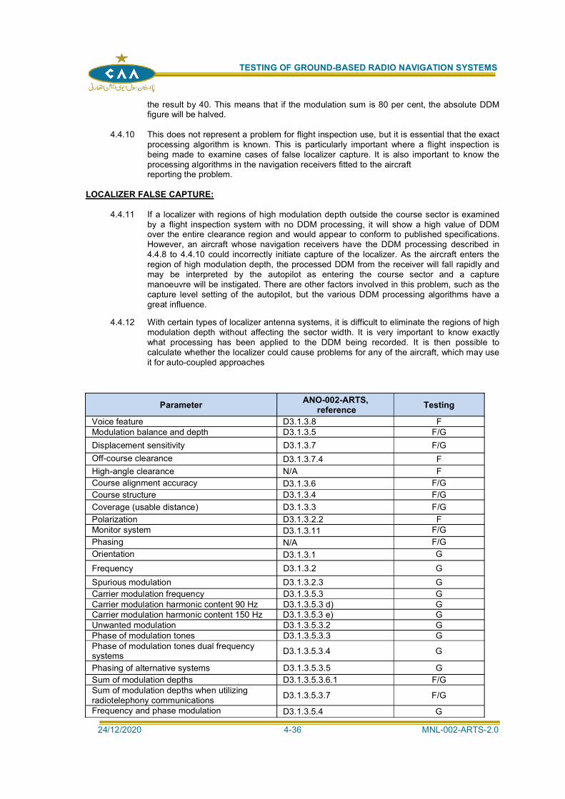
TESTING OF GROUND-BASED RADIO NAVIGATION SYSTEMS
24/12/2020 4-36 MNL-002-ARTS-2.0
the result by 40. This means that if the modulation sum is 80 per cent, the absolute DDMfigure will be halved.
4.4.10 This does not represent a problem for flight inspection use, but it is essential that the exactprocessing algorithm is known. This is particularly important where a flight inspection isbeing made to examine cases of false localizer capture. It is also important to know theprocessing algorithms in the navigation receivers fitted to the aircraftreporting the problem.
LOCALIZER FALSE CAPTURE:
4.4.11 If a localizer with regions of high modulation depth outside the course sector is examinedby a flight inspection system with no DDM processing, it will show a high value of DDMover the entire clearance region and would appear to conform to published specifications.However, an aircraft whose navigation receivers have the DDM processing described in4.4.8 to 4.4.10 could incorrectly initiate capture of the localizer. As the aircraft enters theregion of high modulation depth, the processed DDM from the receiver will fall rapidly andmay be interpreted by the autopilot as entering the course sector and a capturemanoeuvre will be instigated. There are other factors involved in this problem, such as thecapture level setting of the autopilot, but the various DDM processing algorithms have agreat influence.
4.4.12 With certain types of localizer antenna systems, it is difficult to eliminate the regions of highmodulation depth without affecting the sector width. It is very important to know exactlywhat processing has been applied to the DDM being recorded. It is then possible tocalculate whether the localizer could cause problems for any of the aircraft, which may useit for auto-coupled approaches
Parameter ANO-002-ARTS, reference Testing
Voice feature D3.1.3.8 FModulation balance and depth D3.1.3.5 F/GDisplacement sensitivity D3.1.3.7 F/GOff-course clearance D3.1.3.7.4 FHigh-angle clearance N/A FCourse alignment accuracy D3.1.3.6 F/GCourse structure D3.1.3.4 F/GCoverage (usable distance) D3.1.3.3 F/GPolarization D3.1.3.2.2 FMonitor system D3.1.3.11 F/GPhasing N/A F/GOrientation D3.1.3.1 GFrequency D3.1.3.2 GSpurious modulation D3.1.3.2.3 GCarrier modulation frequency D3.1.3.5.3 GCarrier modulation harmonic content 90 Hz D3.1.3.5.3 d) GCarrier modulation harmonic content 150 Hz D3.1.3.5.3 e) GUnwanted modulation D3.1.3.5.3.2 GPhase of modulation tones D3.1.3.5.3.3 GPhase of modulation tones dual frequencysystems D3.1.3.5.3.4 G
Phasing of alternative systems D3.1.3.5.3.5 GSum of modulation depths D3.1.3.5.3.6.1 F/GSum of modulation depths when utilizingradiotelephony communications D3.1.3.5.3.7 F/G
Frequency and phase modulation D3.1.3.5.4 G
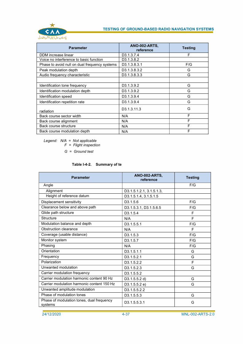
TESTING OF GROUND-BASED RADIO NAVIGATION SYSTEMS
24/12/2020 4-37 MNL-002-ARTS-2.0
Parameter ANO-002-ARTS, reference Testing
DDM increase linear D3.1.3.7.4 FVoice no interference to basic function D3.1.3.8.2Phase to avoid null on dual frequency systems D3.1.3.8.3.1 F/GPeak modulation depth D3.1.3.8.3.2 GAudio frequency characteristic D3.1.3.8.3.3 G
Identification tone frequency D3.1.3.9.2 GIdentification modulation depth D3.1.3.9.2 GIdentification speed D3.1.3.9.4 GIdentification repetition rate D3.1.3.9.4 G
radiation D3.1.3.11.3 G
Back course sector width N/A FBack course alignment N/A FBack course structure N/A FBack course modulation depth N/A F
Legend: N/A = Not applicable F = Flight inspection
G = Ground test
Table I-4-2. Summary of te
Parameter ANO-002-ARTS, reference Testing
Angle F/GAlignment D3.1.5.1.2.1, 3.1.5.1.3,Height of reference datum D3.1.5.1.4, 3.1.5.1.5
Displacement sensitivity D3.1.5.6 F/GClearance below and above path D3.1.5.3.1, D3.1.5.6.5 F/GGlide path structure D3.1.5.4 FStructure N/A FModulation balance and depth D3.1.5.5.1 F/GObstruction clearance N/A FCoverage (usable distance) D3.1.5.3 F/GMonitor system D3.1.5.7 F/GPhasing N/A F/GOrientation D3.1.5.1.1 GFrequency D3.1.5.2.1 GPolarization D3.1.5.2.2 FUnwanted modulation D3.1.5.2.3 GCarrier modulation frequency D3.1.5.5.2Carrier modulation harmonic content 90 Hz D3.1.5.5.2 d) GCarrier modulation harmonic content 150 Hz D3.1.5.5.2 e) GUnwanted amplitude modulation D3.1.5.5.2.2Phase of modulation tones D3.1.5.5.3 GPhase of modulation tones, dual frequencysystems D3.1.5.5.3.1 G
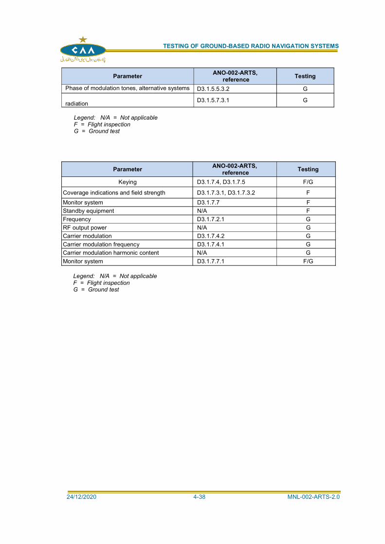
TESTING OF GROUND-BASED RADIO NAVIGATION SYSTEMS
24/12/2020 4-38 MNL-002-ARTS-2.0
Parameter ANO-002-ARTS, reference Testing
Phase of modulation tones, alternative systems D3.1.5.5.3.2 G
radiation D3.1.5.7.3.1 G
Legend: N/A = Not applicableF = Flight inspectionG = Ground test
Parameter ANO-002-ARTS, reference Testing
Keying D3.1.7.4, D3.1.7.5 F/G
Coverage indications and field strength D3.1.7.3.1, D3.1.7.3.2 FMonitor system D3.1.7.7 FStandby equipment N/A FFrequency D3.1.7.2.1 GRF output power N/A GCarrier modulation D3.1.7.4.2 GCarrier modulation frequency D3.1.7.4.1 GCarrier modulation harmonic content N/A GMonitor system D3.1.7.7.1 F/G
Legend: N/A = Not applicableF = Flight inspectionG = Ground test
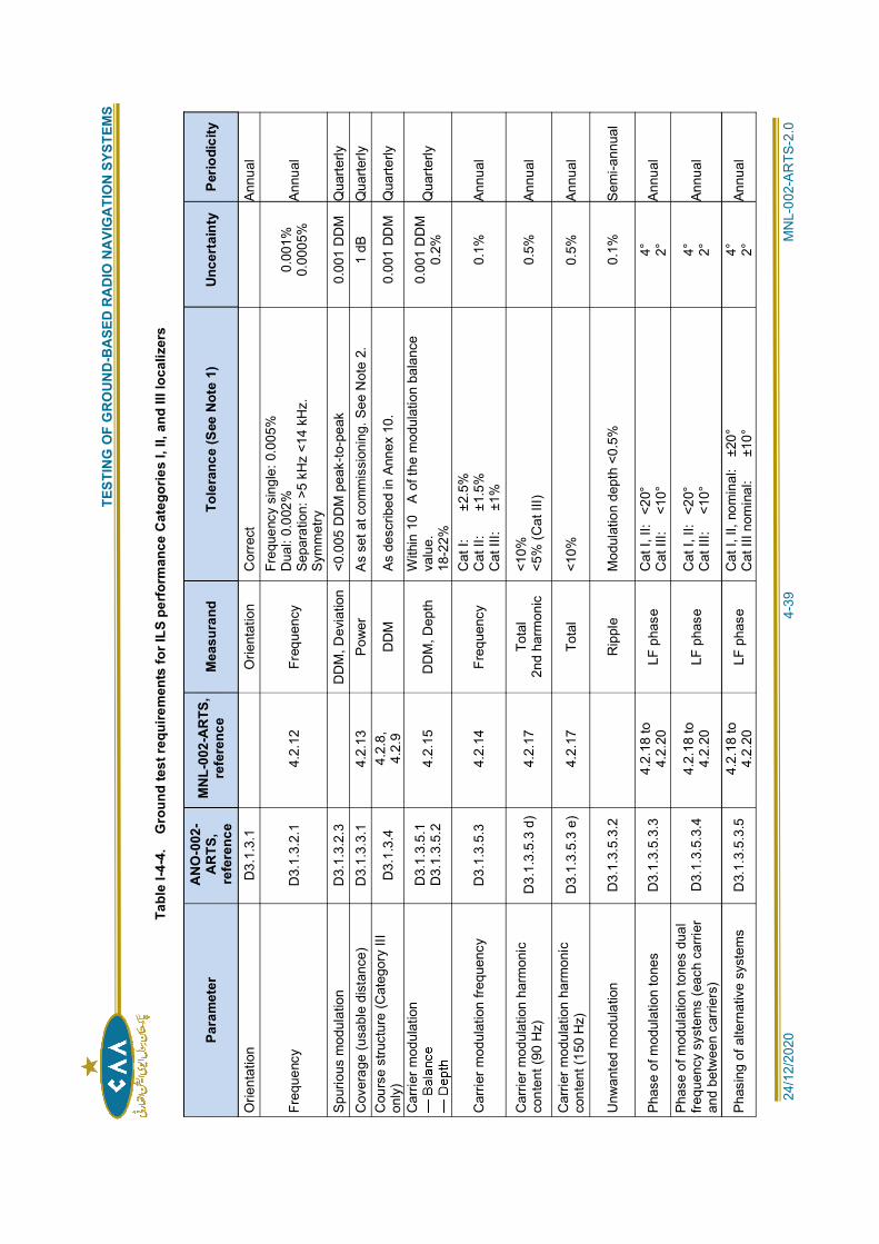
T
ESTI
NG
OF
GR
OU
ND
-BA
SED
RA
DIO
NA
VIG
ATI
ON
SYS
TEM
S
24/1
2/20
20
4
-39
MN
L-00
2-A
RTS
-2.0
Tabl
e I-4
-4.
Gro
und
test
requ
irem
ents
for I
LS p
erfo
rman
ce C
ateg
orie
s I,
II, a
nd II
I loc
aliz
ers
Para
met
erA
NO
-002
-A
RTS
,re
fere
nce
MN
L-00
2-A
RTS
,re
fere
nce
Mea
sura
ndTo
lera
nce
(See
Not
e 1)
Unce
rtai
nty
Perio
dici
ty
Orie
ntat
ion
D3.
1.3.
1O
rient
atio
n C
orre
ctAn
nual
Freq
uenc
y D
3.1.
3.2.
1 4.
2.12
Fr
eque
ncy
Freq
uenc
y si
ngle
: 0.0
05%
Dua
l: 0.
002%
Sepa
ratio
n: >
5 kH
z <1
4 kH
z.Sy
mm
etry
0.00
1%0.
0005
%An
nual
Spur
ious
mod
ulat
ion
D3.
1.3.
2.3
DD
M, D
evia
tion
<0.0
05 D
DM
pea
k-to
-pea
k 0.
001
DD
M
Qua
rterly
Cov
erag
e (u
sabl
e di
stan
ce)
D3.
1.3.
3.1
4.2.
13
Pow
er
As
set a
t com
mis
sion
ing.
See
Not
e 2.
1
dB
Qua
rterly
Cou
rse
stru
ctur
e (C
ateg
ory
IIIon
ly)
D3.
1.3.
44.
2.8,
4.2.
9D
DM
As
des
crib
ed in
Ann
ex 1
0.
0.00
1 D
DM
Q
uarte
rly
Car
rier m
odul
atio
nD
3.1.
3.5.
1D
3.1.
3.5.
24.
2.15
D
DM
, Dep
thW
ithin
10
A of
the
mod
ulat
ion
bala
nce
valu
e.18
-22%
0.00
1 D
DM
0.2%
Qua
rterly
Car
rier m
odul
atio
n fre
quen
cy
D3.
1.3.
5.3
4.2.
14
Freq
uenc
yC
at I:
±2.
5%C
at II
:
±1.
5%C
at II
I:
±1%
0.1%
Annu
al
Car
rier m
odul
atio
n ha
rmon
icco
nten
t (90
Hz)
D3.
1.3.
5.3
d)
4.2.
17To
tal
2nd
harm
onic
<10%
<5%
(Cat
III)
0.5%
Annu
al
Car
rier m
odul
atio
n ha
rmon
icco
nten
t (15
0 H
z)D
3.1.
3.5.
3 e)
4.
2.17
To
tal
<10%
0.
5%An
nual
Unw
ante
d m
odul
atio
n D
3.1.
3.5.
3.2
Rip
ple
Mod
ulat
ion
dept
h <0
.5%
0.
1%
Sem
i-ann
ual
Phas
e of
mod
ulat
ion
tone
s D
3.1.
3.5.
3.3
4.2.
18 to
4.2.
20LF
pha
seC
at I,
II:
<20°
Cat
III:
<1
0°4° 2°
Annu
al
Phas
e of
mod
ulat
ion
tone
s du
alfre
quen
cy s
yste
ms
(eac
h ca
rrier
and
betw
een
carr
iers
)D
3.1.
3.5.
3.4
4.2.
18 to
4.2.
20LF
pha
seC
at I,
II:
<20°
Cat
III:
<1
0°4° 2°
Annu
al
Phas
ing
of a
ltern
ativ
e sy
stem
s D
3.1.
3.5.
3.5
4.2.
18 to
4.2.
20LF
pha
seC
at I,
II, n
omin
al:
±20
°C
at II
I nom
inal
:
±10
°4° 2°
Annu
al
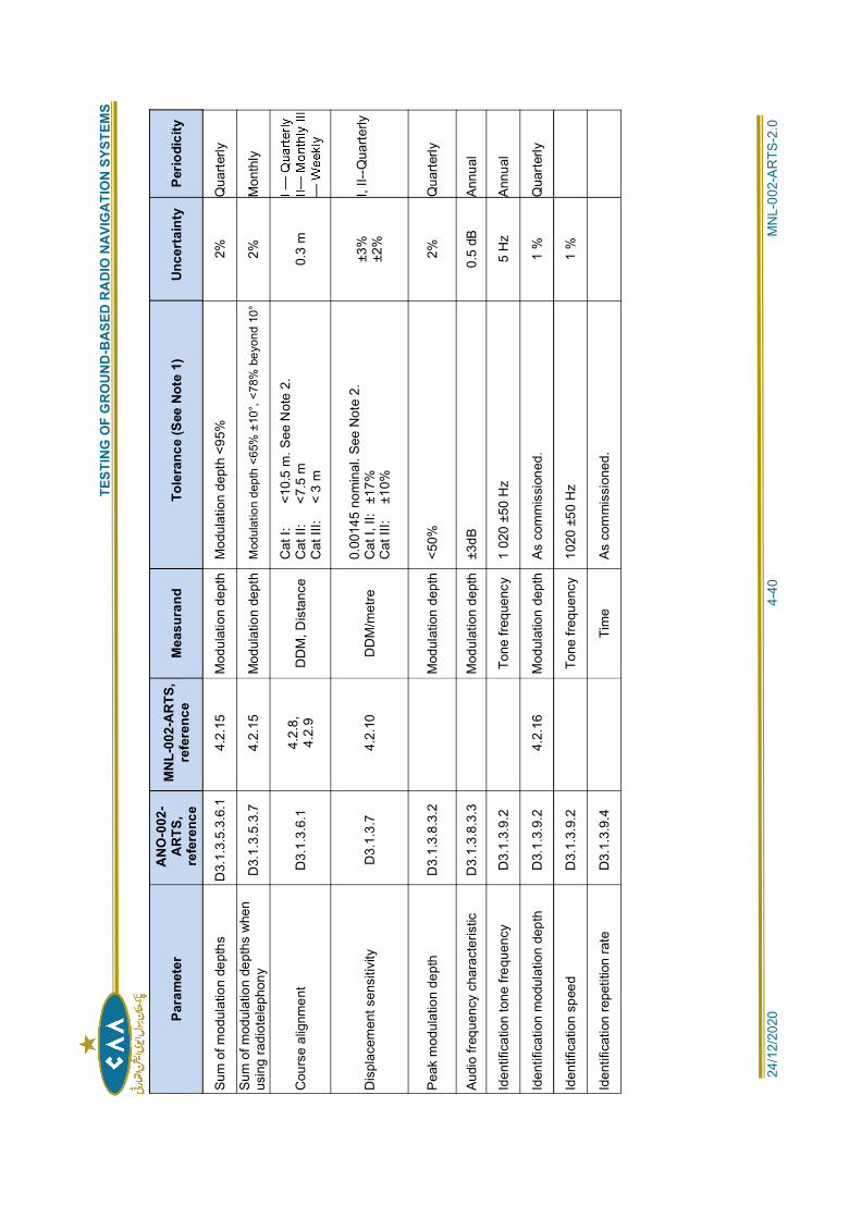
T
ESTI
NG
OF
GR
OU
ND
-BA
SED
RA
DIO
NA
VIG
ATI
ON
SYS
TEM
S
24/1
2/20
20
4
-40
MN
L-00
2-A
RTS
-2.0
Para
met
erA
NO
-002
-A
RTS
,re
fere
nce
MN
L-00
2-A
RTS
,re
fere
nce
Mea
sura
ndTo
lera
nce
(See
Not
e 1)
Unce
rtai
nty
Perio
dici
ty
Sum
of m
odul
atio
n de
pths
D
3.1.
3.5.
3.6.
1 4.
2.15
M
odul
atio
n de
pth
Mod
ulat
ion
dept
h <9
5%
2%
Qua
rterly
Sum
of m
odul
atio
n de
pths
whe
nus
ing
radi
otel
epho
nyD
3.1.
3.5.
3.7
4.2.
15
Mod
ulat
ion
dept
hM
odul
atio
n de
pth
<65%
±10
°, <7
8% b
eyon
d 10
°2%
M
onth
ly
Cou
rse
alig
nmen
t D
3.1.
3.6.
14.
2.8,
4.2.
9D
DM
, Dis
tanc
eC
at I:
<10.
5 m
. See
Not
e 2.
Cat
II:
<7
.5 m
Cat
III:
<
3 m
0.3
m
Dis
plac
emen
t sen
sitiv
ity
D3.
1.3.
7 4.
2.10
D
DM
/met
re0.
0014
5 no
min
al. S
ee N
ote
2.C
at I,
II:
±17%
Cat
III:
±1
0%
±3%
±2%
I, II-
-Qua
rterly
Peak
mod
ulat
ion
dept
h D
3.1.
3.8.
3.2
Mod
ulat
ion
dept
h <5
0%
2%
Qua
rterly
Audi
o fre
quen
cy c
hara
cter
istic
D
3.1.
3.8.
3.3
Mod
ulat
ion
dept
h ±3
dB
0.5
dBAn
nual
Iden
tific
atio
n to
ne fr
eque
ncy
D3.
1.3.
9.2
Tone
freq
uenc
y 1
020
±50
Hz
5 H
zAn
nual
Iden
tific
atio
n m
odul
atio
n de
pth
D3.
1.3.
9.2
4.2.
16
Mod
ulat
ion
dept
h As
com
mis
sion
ed.
1 %
Q
uarte
rly
Iden
tific
atio
n sp
eed
D3.
1.3.
9.2
Tone
freq
uenc
y 10
20 ±
50 H
z 1
%
Iden
tific
atio
n re
petit
ion
rate
D
3.1.
3.9.
4Ti
me
As c
omm
issi
oned
.
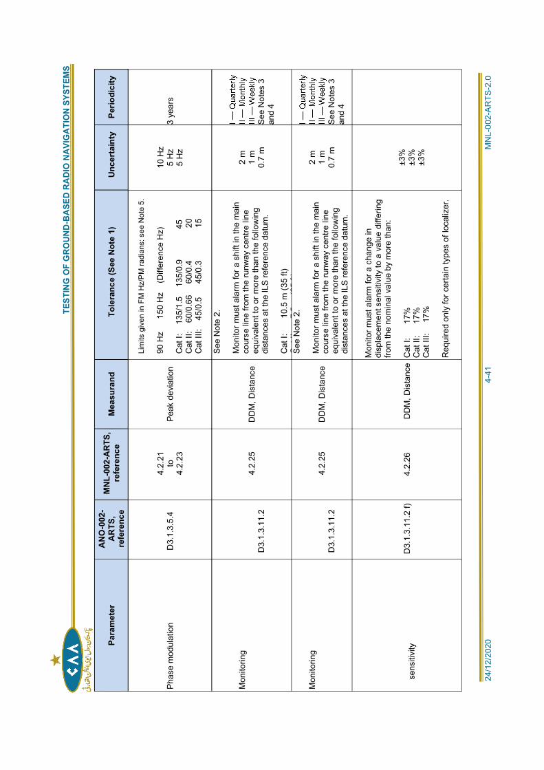
T
ESTI
NG
OF
GR
OU
ND
-BA
SED
RA
DIO
NA
VIG
ATI
ON
SYS
TEM
S
24/1
2/20
20
4
-41
MN
L-00
2-A
RTS
-2.0
Para
met
erA
NO
-002
-A
RTS
,re
fere
nce
MN
L-00
2-A
RTS
,re
fere
nce
Mea
sura
ndTo
lera
nce
(See
Not
e 1)
Unce
rtai
nty
Perio
dici
ty
Phas
e m
odul
atio
n D
3.1.
3.5.
44.
2.21
to4.
2.23
Peak
dev
iatio
n
Lim
its g
iven
in F
M H
z/P
M ra
dian
s: s
ee N
ote
5.
90 H
z
150
Hz
(D
iffer
ence
Hz)
Cat
I:
135
/1.5
1
35/0
.9
4
5C
at II
: 6
0/0.
66
60/
0.4
20
Cat
III:
45
/0.5
45/0
.3
1
5
10 H
z5
Hz
5 H
z3
year
s
Mon
itorin
g
D3.
1.3.
11.2
4.2.
25
DD
M, D
ista
nce
See
Not
e 2.
Mon
itor m
ust a
larm
for a
shi
ft in
the
mai
nco
urse
line
from
the
runw
ay c
entre
line
equi
vale
nt to
or m
ore
than
the
follo
win
gdi
stan
ces
at th
e IL
S re
fere
nce
datu
m.
Cat
I:
10
.5 m
(35
ft)C
tII
75
(25
ft)
2 m
1 m
0.7
mSe
e N
otes
3an
d 4
Mon
itorin
g
D3.
1.3.
11.2
4.2.
25
DD
M, D
ista
nce
See
Not
e 2.
Mon
itor m
ust a
larm
for a
shi
ft in
the
mai
nco
urse
line
from
the
runw
ay c
entre
line
equi
vale
nt to
or m
ore
than
the
follo
win
gdi
stan
ces
at th
e IL
S re
fere
nce
datu
m.
2 m
1 m
0.7
mSe
e N
otes
3an
d 4
sens
itivi
tyD
3.1.
3.11
.2 f)
4.
2.26
D
DM
, Dis
tanc
e
Mon
itor m
ust a
larm
for a
cha
nge
indi
spla
cem
ent s
ensi
tivity
to a
val
ue d
iffer
ing
from
the
nom
inal
val
ue b
y m
ore
than
:
Cat
I:
17
%C
at II
:
17%
Cat
III:
17
%
Req
uire
d on
ly fo
r cer
tain
type
s of
loca
lizer
.
±3%
±3%
±3%
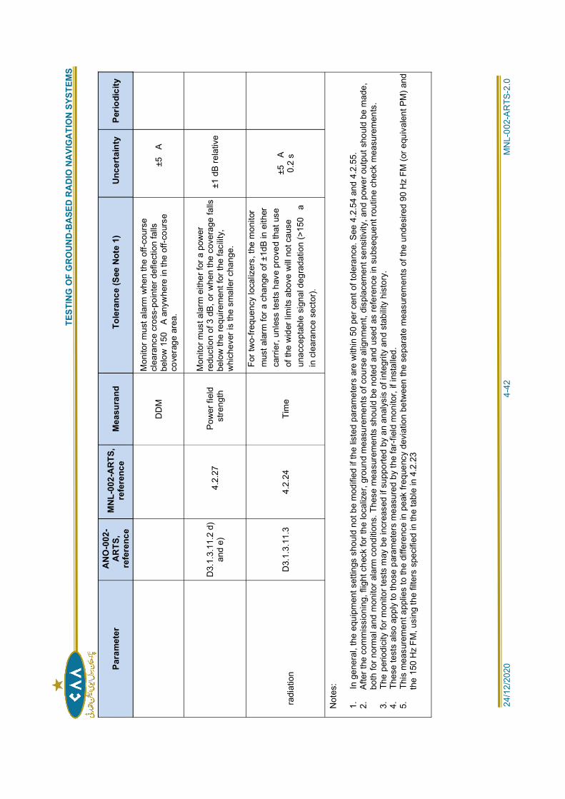
T
ESTI
NG
OF
GR
OU
ND
-BA
SED
RA
DIO
NA
VIG
ATI
ON
SYS
TEM
S
24/1
2/20
20
4
-42
MN
L-00
2-A
RTS
-2.0
Para
met
erA
NO
-002
-A
RTS
,re
fere
nce
MN
L-00
2-A
RTS
,re
fere
nce
Mea
sura
ndTo
lera
nce
(See
Not
e 1)
Unce
rtai
nty
Perio
dici
ty
DD
M
Mon
itor m
ust a
larm
whe
n th
e of
f-cou
rse
clea
ranc
e cr
oss-
poin
ter d
efle
ctio
n fa
llsbe
low
150
A an
ywhe
re in
the
off-c
ours
eco
vera
ge a
rea.
±5A
D3.
1.3.
11.2
d)
and
e)4.
2.27
Pow
er fi
eld
stre
ngth
Mon
itor m
ust a
larm
eith
er fo
r a p
ower
redu
ctio
n of
3 d
B, o
r whe
n th
e co
vera
ge fa
llsbe
low
the
requ
irem
ent f
or th
e fa
cilit
y,w
hich
ever
is th
e sm
alle
r cha
nge.
±1 d
B re
lativ
e
radi
atio
nD
3.1.
3.11
.3
4.2.
24
Tim
e
For t
wo-
frequ
ency
loca
lizer
s, th
e m
onito
rm
ust a
larm
for a
cha
nge
of ±
1dB
in e
ither
carri
er, u
nles
s te
sts
have
pro
ved
that
use
of th
e w
ider
lim
its a
bove
will
not c
ause
unac
cept
able
sig
nal d
egra
datio
n (>
150
ain
cle
aran
ce s
ecto
r).
±5A
0.2
s
Not
es:
1.
In
gene
ral,
the
equi
pmen
t set
tings
sho
uld
not b
e m
odifi
ed if
the
liste
d pa
ram
eter
s ar
e w
ithin
50
per c
ent o
f tol
eran
ce. S
ee 4
.2.5
4 an
d 4.
2.55
.2.
A
fter t
he c
omm
issi
onin
g, fl
ight
che
ck fo
r the
loca
lizer
, gro
und
mea
sure
men
ts o
f cou
rse
alig
nmen
t, di
spla
cem
ent s
ensi
tivity
, and
pow
er o
utpu
t sho
uld
be m
ade,
both
for n
orm
al a
nd m
onito
r ala
rm c
ondi
tions
. The
se m
easu
rem
ents
sho
uld
be n
oted
and
use
d as
refe
renc
e in
sub
sequ
ent r
outin
e ch
eck
mea
sure
men
ts.
3.
The
per
iodi
city
for m
onito
r tes
ts m
ay b
e in
crea
sed
if su
ppor
ted
by a
n an
alys
is o
f int
egrit
y an
d st
abilit
y hi
stor
y.4.
T
hese
test
s al
so a
pply
to th
ose
para
met
ers
mea
sure
d by
the
far-
field
mon
itor,
if in
stal
led.
5.
Thi
s m
easu
rem
ent a
pplie
s to
the
diffe
renc
e in
pea
k fre
quen
cy d
evia
tion
betw
een
the
sepa
rate
mea
sure
men
ts o
f the
und
esire
d 90
Hz
FM (o
r equ
ival
ent P
M) a
ndth
e 15
0 H
z FM
, usi
ng th
e fil
ters
spe
cifie
d in
the
tabl
e in
4.2
.23
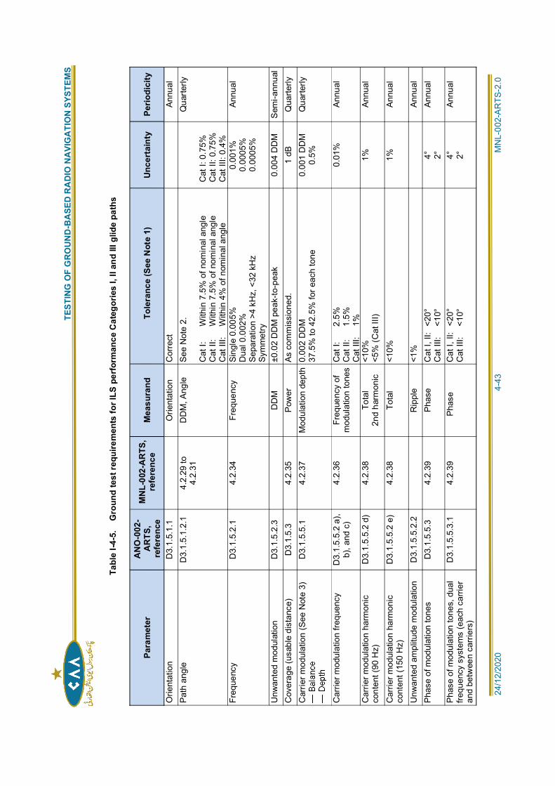
T
ESTI
NG
OF
GR
OU
ND
-BA
SED
RA
DIO
NA
VIG
ATI
ON
SYS
TEM
S
24/1
2/20
20
4
-43
MN
L-00
2-A
RTS
-2.0
Tabl
e I-4
-5.
Gro
und
test
requ
irem
ents
for I
LS p
erfo
rman
ce C
ateg
orie
s I,
II an
d III
glid
e pa
ths
Para
met
erA
NO
-002
-A
RTS
,re
fere
nce
MN
L-00
2-A
RTS
,re
fere
nce
Mea
sura
ndTo
lera
nce
(See
Not
e 1)
Unce
rtai
nty
Perio
dici
ty
Orie
ntat
ion
D3.
1.5.
1.1
Orie
ntat
ion
Cor
rect
Annu
alPa
th a
ngle
D
3.1.
5.1.
2.1
4.2.
29 to
4.2.
31D
DM
, Ang
le
See
Not
e 2.
Cat
I:
W
ithin
7.5
% o
f nom
inal
ang
leC
at II
:
With
in 7
.5%
of n
omin
al a
ngle
Cat
III:
W
ithin
4%
of n
omin
al a
ngle
Cat
I: 0
.75%
Cat
II: 0
.75%
Cat
III:
0.4%
Qua
rterly
Freq
uenc
y D
3.1.
5.2.
1 4.
2.34
Fr
eque
ncy
Sing
le 0
.005
%D
ual 0
.002
%Se
para
tion
>4 k
Hz,
<32
kH
zSy
mm
etry
0.00
1%0.
0005
%0.
0005
%
Annu
al
Unw
ante
d m
odul
atio
n D
3.1.
5.2.
3D
DM
±0
.02
DD
M p
eak-
to-p
eak
0.00
4 D
DM
S
emi-a
nnua
lC
over
age
(usa
ble
dist
ance
) D
3.1.
5.3
4.2.
35
Pow
er
As c
omm
issi
oned
. 1
dB
Qua
rterly
Car
rier m
odul
atio
n (S
ee N
ote
3)D
3.1.
5.5.
1 4.
2.37
M
odul
atio
n de
pth
0.00
2 D
DM
37.5
% to
42.
5% fo
r eac
h to
ne0.
001
DD
M0.
5%Q
uarte
rly
Car
rier m
odul
atio
n fre
quen
cy
D3.
1.5.
5.2
a),
b), a
nd c
)4.
2.36
Fr
eque
ncy
ofm
odul
atio
n to
nes
Cat
I:
2.
5%C
at II
:
1.5%
Cat
III:
1%
0.01
%
Annu
al
Car
rier m
odul
atio
n ha
rmon
icco
nten
t (90
Hz)
D3.
1.5.
5.2
d)
4.2.
38
Tota
l2n
d ha
rmon
ic<1
0%<5
% (C
at II
I)1%
An
nual
Car
rier m
odul
atio
n ha
rmon
icco
nten
t (15
0 H
z)D
3.1.
5.5.
2 e)
4.
2.38
To
tal
<10%
1%
An
nual
Unw
ante
d am
plitu
de m
odul
atio
n D
3.1.
5.5.
2.2
Rip
ple
<1%
Annu
alPh
ase
of m
odul
atio
n to
nes
D3.
1.5.
5.3
4.2.
39
Phas
e C
at I,
II:
<20°
Cat
III:
<1
0°4° 2°
Annu
al
Phas
e of
mod
ulat
ion
tone
s, d
ual
frequ
ency
sys
tem
s (e
ach
carri
eran
d be
twee
n ca
rrie
rs)
D3.
1.5.
5.3.
1 4.
2.39
Ph
ase
Cat
I, II
: <2
0°C
at II
I:
<10°
4° 2°An
nual
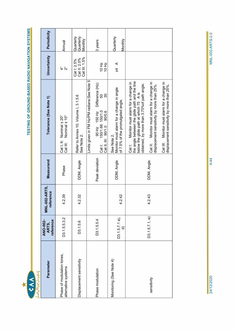
T
ESTI
NG
OF
GR
OU
ND
-BA
SED
RA
DIO
NA
VIG
ATI
ON
SYS
TEM
S
24/1
2/20
20
4
-44
MN
L-00
2-A
RTS
-2.0
Para
met
erA
NO
-002
-A
RTS
,re
fere
nce
MN
L-00
2-A
RTS
,re
fere
nce
Mea
sura
ndTo
lera
nce
(See
Not
e 1)
Unce
rtai
nty
Perio
dici
ty
Phas
e of
mod
ulat
ion
tone
s,al
tern
ativ
e sy
stem
sD
3.1.
5.5.
3.2
4.2.
39
Phas
eC
at I,
II:
Nom
inal
± 2
0°C
at II
I:
Nom
inal
± 1
0°4° 2°
Annu
al
Dis
plac
emen
t sen
sitiv
ity
D3.
1.5.
6 4.
2.32
D
DM
, Ang
leR
efer
to A
nnex
10,
Vol
ume
I, 3.
1.5.
6Se
e N
ote
2.
Cat
I: 2
.5%
Cat
II: 2
.0%
Cat
III:
1.5%
Qua
rterly
Qua
rterly
Mon
thly
Phas
e m
odul
atio
n D
3.1.
5.5.
4Pe
ak d
evia
tion
Lim
its g
iven
in F
M H
z/PM
radi
ans:
See
Not
e 5
9
0 H
z
150
Hz
D
iffer
ence
(Hz)
Cat
I:
15
0/1.
66 1
50/1
.0
50
Cat
II, I
II:
90/1
.0
90/
0.6
3010
Hz
10 H
z
3 ye
ars
Mon
itorin
g (S
ee N
ote
4)
D3.
1.5.
7.1
a),
d)4.
2.42
DD
M, A
ngle
See
Not
e 2.
Mon
itor m
ust a
larm
for a
cha
nge
in a
ngle
of 7
.5%
of t
he p
rom
ulga
ted
angl
e.±4
AQ
uarte
rly
Mon
thly
sens
itivi
tyD
3.1.
5.7.
1, e
) 4.
2.43
D
DM
, Ang
le
Cat
I:
M
onito
r mus
t ala
rm fo
r a c
hang
e in
the
angl
e be
twee
n th
e gl
ide
path
and
the
line
belo
w th
e gl
ide
path
at w
hich
75
A is
obta
ined
, by
mor
e th
an 3
.75%
of p
ath
angl
e.
Cat
II:
M
onito
r mus
t ala
rm fo
r a c
hang
e in
disp
lace
men
t sen
sitiv
ity b
y m
ore
than
25%
.
Cat
III:
M
onito
r mus
t ala
rm fo
r a c
hang
e in
disp
lace
men
t sen
sitiv
ity b
y m
ore
than
25%
.
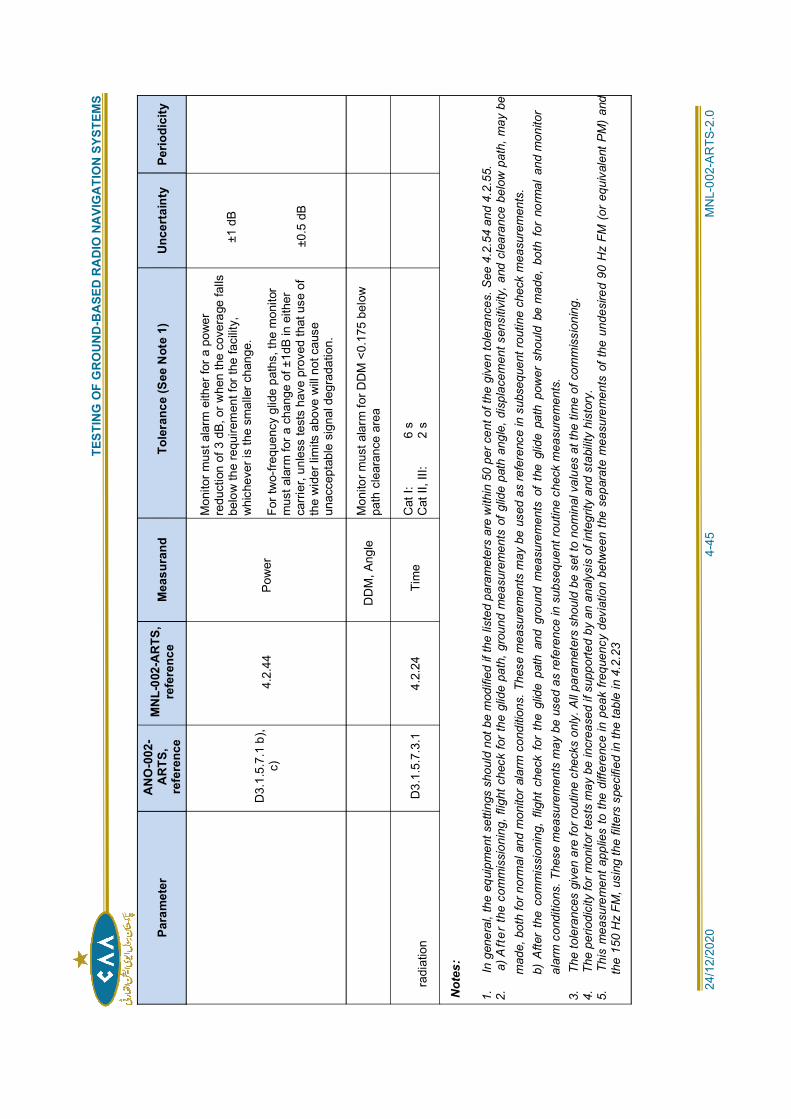
T
ESTI
NG
OF
GR
OU
ND
-BA
SED
RA
DIO
NA
VIG
ATI
ON
SYS
TEM
S
24/1
2/20
20
4
-45
MN
L-00
2-A
RTS
-2.0
Para
met
erA
NO
-002
-A
RTS
,re
fere
nce
MN
L-00
2-A
RTS
,re
fere
nce
Mea
sura
ndTo
lera
nce
(See
Not
e 1)
Unce
rtai
nty
Perio
dici
ty
D3.
1.5.
7.1
b),
c)4.
2.44
Po
wer
Mon
itor m
ust a
larm
eith
er fo
r a p
ower
redu
ctio
n of
3 d
B, o
r whe
n th
e co
vera
ge fa
llsbe
low
the
requ
irem
ent f
or th
e fa
cilit
y,w
hich
ever
is th
e sm
alle
r cha
nge.
For t
wo-
frequ
ency
glid
e pa
ths,
the
mon
itor
mus
t ala
rm fo
r a c
hang
e of
±1d
B in
eith
erca
rrier
, unl
ess
test
s ha
ve p
rove
d th
at u
se o
fth
e w
ider
lim
its a
bove
will
not
cau
seun
acce
ptab
le s
igna
l deg
rada
tion.
±1 d
B
±0.5
dB
DD
M, A
ngle
Mon
itor m
ust a
larm
for D
DM
<0.
175
belo
wpa
th c
lear
ance
are
a
radi
atio
nD
3.1.
5.7.
3.1
4.2.
24
Tim
eC
at I:
6 s
Cat
II, I
II:
2
s
Not
es:
1.
In
gene
ral,
the
equi
pmen
t set
tings
sho
uld
not b
e m
odifi
ed if
the
liste
d pa
ram
eter
s ar
e w
ithin
50
per c
ent o
f the
giv
en to
lera
nces
. See
4.2
.54
and
4.2.
55.
2.
a)
Aft
er th
e co
mm
issi
onin
g, fl
ight
che
ck fo
r the
glid
e pa
th, g
roun
d m
easu
rem
ents
of g
lide
path
ang
le, d
ispl
acem
ent s
ensi
tivity
, and
cle
aran
ce b
elow
pat
h, m
ay b
em
ade,
bot
h fo
r nor
mal
and
mon
itor a
larm
con
ditio
ns. T
hese
mea
sure
men
ts m
ay b
e us
ed a
s re
fere
nce
in s
ubse
quen
t rou
tine
chec
k m
easu
rem
ents
.b)
Afte
r th
e co
mm
issi
onin
g, f
light
che
ck f
or t
he g
lide
path
and
gro
und
mea
sure
men
ts o
f th
e gl
ide
path
pow
er s
houl
d be
mad
e, b
oth
for
norm
al a
nd m
onito
ral
arm
con
ditio
ns. T
hese
mea
sure
men
ts m
ay b
e us
ed a
s re
fere
nce
in s
ubse
quen
t rou
tine
chec
k m
easu
rem
ents
.3.
T
he to
lera
nces
giv
en a
re fo
r rou
tine
chec
ks o
nly.
All
para
met
ers
shou
ld b
e se
t to
nom
inal
val
ues
at th
e tim
e of
com
mis
sion
ing.
4.
The
per
iodi
city
for m
onito
r tes
ts m
ay b
e in
crea
sed
if su
ppor
ted
by a
n an
alys
is o
f int
egrit
y an
d st
abili
ty h
isto
ry.
5.
Thi
s m
easu
rem
ent a
pplie
s to
the
diffe
renc
e in
pea
k fre
quen
cy d
evia
tion
betw
een
the
sepa
rate
mea
sure
men
ts o
f the
und
esire
d 90
Hz
FM (
or e
quiv
alen
t PM
) an
dth
e 15
0 H
z FM
, usi
ng th
e fil
ters
spe
cifie
d in
the
tabl
e in
4.2
.23
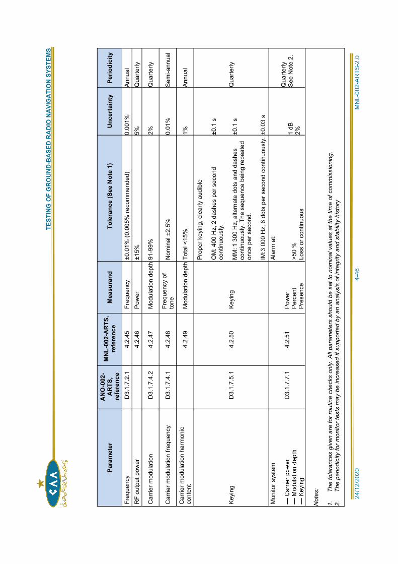
T
ESTI
NG
OF
GR
OU
ND
-BA
SED
RA
DIO
NA
VIG
ATI
ON
SYS
TEM
S
24/1
2/20
20
4
-46
MN
L-00
2-A
RTS
-2.0
Para
met
erA
NO
-002
-A
RTS
,re
fere
nce
MN
L-00
2-A
RTS
,re
fere
nce
Mea
sura
ndTo
lera
nce
(See
Not
e 1)
Unce
rtai
nty
Perio
dici
ty
Freq
uenc
y D
3.1.
7.2.
1 4.
2.45
Fr
eque
ncy
±0.0
1% (0
.005
% re
com
men
ded)
0.
001%
An
nual
RF
outp
ut p
ower
4.2.
46
Pow
er
±15%
5%
Q
uarte
rly
Car
rier m
odul
atio
n D
3.1.
7.4.
2 4.
2.47
M
odul
atio
n de
pth
91-9
9%
2%
Qua
rterly
Car
rier m
odul
atio
n fre
quen
cy
D3.
1.7.
4.1
4.2.
48Fr
eque
ncy
ofto
neN
omin
al ±
2.5%
0.
01%
Se
mi-a
nnua
l
Car
rier m
odul
atio
n ha
rmon
icco
nten
t4.
2.49
M
odul
atio
n de
pth
Tota
l <15
%
1%
Annu
al
Keyi
ng
D3.
1.7.
5.1
4.2.
50
Keyi
ng
Prop
er k
eyin
g, c
lear
ly a
udib
le
OM
: 400
Hz,
2 d
ashe
s pe
r sec
ond
cont
inuo
usly
.
MM
: 1 3
00 H
z, a
ltern
ate
dots
and
das
hes
cont
inuo
usly
. The
seq
uenc
e be
ing
repe
ated
once
per
sec
ond.
IM:3
000
Hz,
6 d
ots
per s
econ
d co
ntin
uous
ly.±0
.1 s
±0.1
s
±0.0
3 s
Qua
rterly
Mon
itor s
yste
m
D3.
1.7.
7.1
4.2.
51Po
wer
Perc
ent
Pres
ence
Alar
m a
t:
>50
%Lo
ss o
r con
tinuo
us
1 dB
2%
Qua
rterly
See
Not
e 2.
Not
es:
1.
The
tole
ranc
es g
iven
are
for r
outin
e ch
ecks
onl
y. A
ll pa
ram
eter
s sh
ould
be
set t
o no
min
al v
alue
s at
the
time
of c
omm
issi
onin
g.2.
T
he p
erio
dici
ty fo
r mon
itor t
ests
may
be
incr
ease
d if
supp
orte
d by
an
anal
ysis
of i
nteg
rity
and
stab
ility
hist
ory
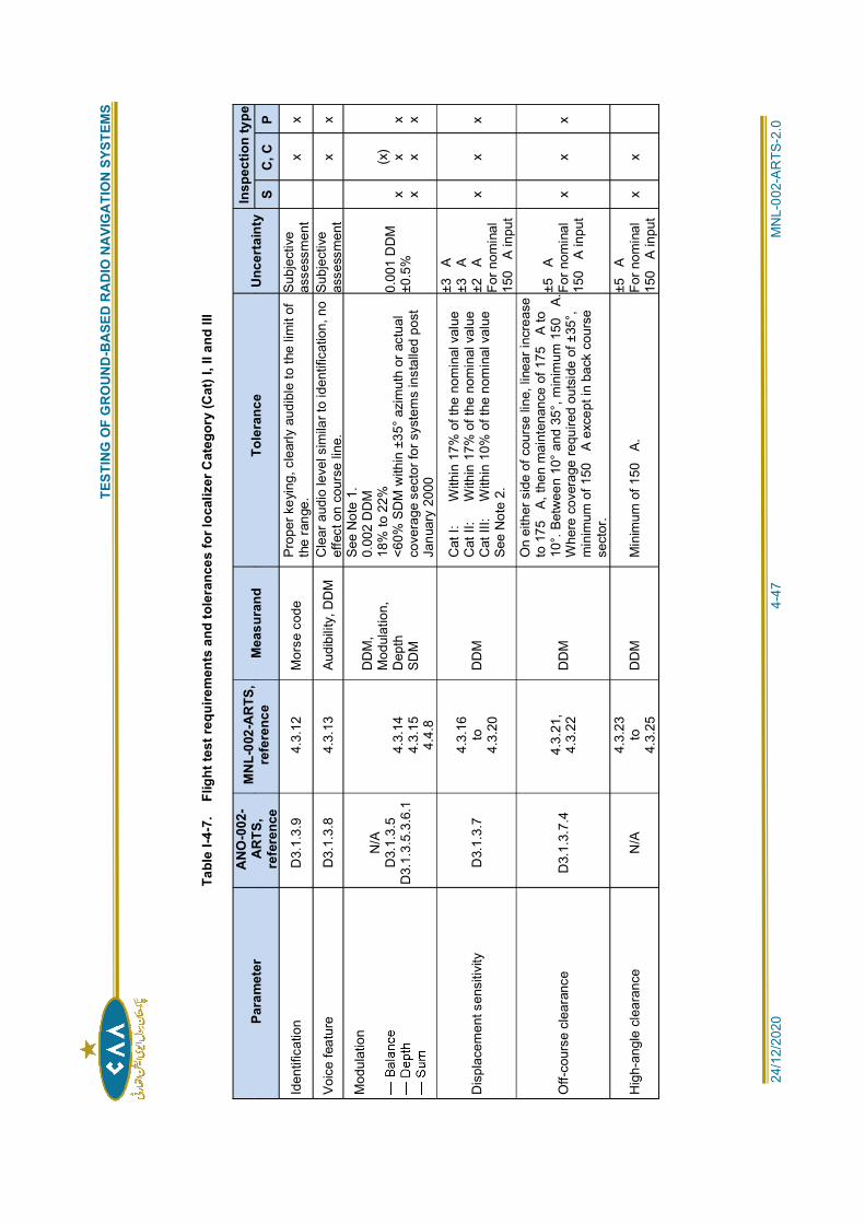
T
ESTI
NG
OF
GR
OU
ND
-BA
SED
RA
DIO
NA
VIG
ATI
ON
SYS
TEM
S
24/1
2/20
20
4
-47
MN
L-00
2-A
RTS
-2.0
Tabl
e I-4
-7.
Flig
ht te
st re
quire
men
ts a
nd to
lera
nces
for l
ocal
izer
Cat
egor
y (C
at) I
, II a
nd II
I
Para
met
erA
NO
-002
-A
RTS
,re
fere
nce
MN
L-00
2-A
RTS
,re
fere
nce
Mea
sura
ndTo
lera
nce
Unce
rtai
nty
Insp
ectio
n ty
peS
C, C
P
Iden
tific
atio
n D
3.1.
3.9
4.3.
12
Mor
se c
ode
Prop
er k
eyin
g, c
lear
ly a
udib
le to
the
limit
ofth
e ra
nge.
Subj
ectiv
eas
sess
men
tx
x
Voic
e fe
atur
e D
3.1.
3.8
4.3.
13
Audi
bilit
y, D
DM
Cle
ar a
udio
leve
l sim
ilar t
o id
entif
icat
ion,
no
effe
ct o
n co
urse
line
.Su
bjec
tive
asse
ssm
ent
x x
Mod
ulat
ion
N/A
D3.
1.3.
5D
3.1.
3.5.
3.6.
14.
3.14
4.3.
154.
4.8
DD
M,
Mod
ulat
ion,
Dep
thSD
M
See
Not
e 1.
0.00
2 D
DM
18%
to 2
2%<6
0% S
DM
with
in ±
35° a
zim
uth
or a
ctua
lco
vera
ge s
ecto
r for
sys
tem
s in
stal
led
post
Janu
ary
2000
0.00
1 D
DM
±0.5
%x x
(x) x x
x x
Dis
plac
emen
t sen
sitiv
ity
D3.
1.3.
74.
3.16
to4.
3.20
DD
M
Cat
I:
W
ithin
17%
of t
he n
omin
al v
alue
Cat
II:
W
ithin
17%
of t
he n
omin
al v
alue
Cat
III:
W
ithin
10%
of t
he n
omin
al v
alue
See
Not
e 2.
±3A
±3A
±2A
For n
omin
al15
0A
inpu
t
x x
x
Off-
cour
se c
lear
ance
D
3.1.
3.7.
44.
3.21
,4.
3.22
DD
M
On
eith
er s
ide
of c
ours
e lin
e, li
near
incr
ease
to 1
75A,
then
mai
nten
ance
of 1
75A
to10
°. Be
twee
n 10
° and
35°
, min
imum
150
A.W
here
cov
erag
e re
quire
d ou
tsid
e of
±35
°,m
inim
um o
f 150
A ex
cept
in b
ack
cour
sese
ctor
.
±5A
For n
omin
al15
0A
inpu
tx
x x
Hig
h-an
gle
clea
ranc
e N
/A4.
3.23
to4.
3.25
DD
M
Min
imum
of 1
50A.
±5A
For n
omin
al15
0A
inpu
tx
x
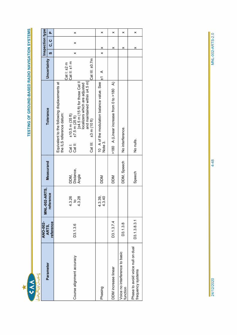
T
ESTI
NG
OF
GR
OU
ND
-BA
SED
RA
DIO
NA
VIG
ATI
ON
SYS
TEM
S
24/1
2/20
20
4
-48
MN
L-00
2-A
RTS
-2.0
Para
met
erA
NO
-002
-A
RTS
,re
fere
nce
MN
L-00
2-A
RTS
,re
fere
nce
Mea
sura
ndTo
lera
nce
Unce
rtai
nty
Insp
ectio
n ty
peS
C, C
P
Cou
rse
alig
nmen
t acc
urac
y D
3.1.
3.6
4.3.
26to
4.3.
28
DD
M,
Dis
tanc
e,An
gle
Equi
vale
nt to
the
follo
win
g di
spla
cem
ents
at
the
ILS
refe
renc
e da
tum
:
Cat
I:
±1
0.5
m (3
5 ft)
Cat
II:
±7
.5 m
(25
ft)
[±4
.5 m
(15
ft) fo
r tho
se C
at II
loca
lizer
s w
hich
are
adj
uste
dan
d m
aint
aine
d w
ithin
±4.
5 m
]C
at II
I:
±3 m
(10
ft)
Cat
I: ±
2 m
Cat
II: ±
1 m
Cat
III:
±0.7
m
x x
x
Phas
ing
4.3.
39,
4.3.
40D
DM
10A
of t
he m
odul
atio
n ba
lanc
e va
lue.
See
Not
e 3.
±1A
x x
x
DD
M in
crea
se li
near
D
3.1.
3.7.
4D
DM
>
180
A (L
inea
r inc
reas
e fro
m 0
to >
180
A)
x
x
Voic
e no
inte
rfere
nce
to b
asic
func
tion
D3.
1.3.
8D
DM
, Spe
ech
No
inte
rfere
nce.
x x
Phas
e to
avo
id v
oice
nul
l on
dual
frequ
ency
sys
tem
sD
3.1.
3.8.
3.1
Spee
ch
No
nulls
.
x
x
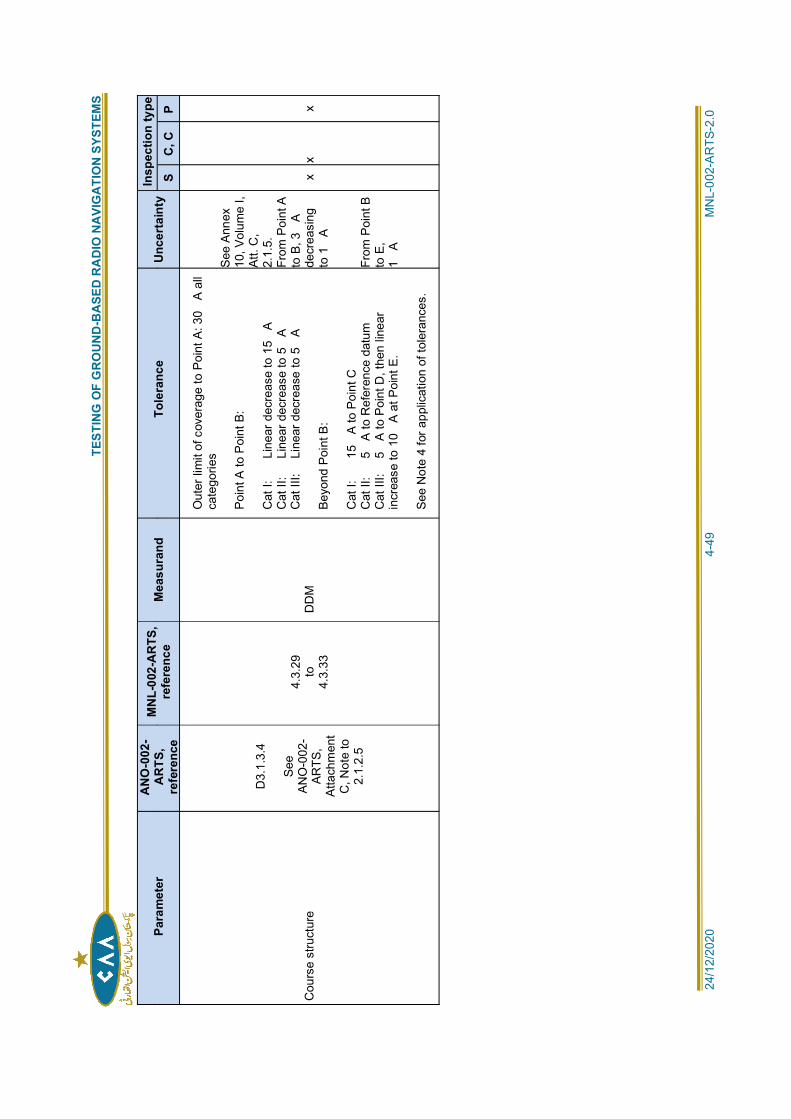
T
ESTI
NG
OF
GR
OU
ND
-BA
SED
RA
DIO
NA
VIG
ATI
ON
SYS
TEM
S
24/1
2/20
20
4
-49
MN
L-00
2-A
RTS
-2.0
Para
met
erA
NO
-002
-A
RTS
,re
fere
nce
MN
L-00
2-A
RTS
,re
fere
nce
Mea
sura
ndTo
lera
nce
Unce
rtai
nty
Insp
ectio
n ty
peS
C, C
P
Cou
rse
stru
ctur
e
D3.
1.3.
4
See
ANO
-002
-AR
TS,
Atta
chm
ent
C, N
ote
to2.
1.2.
5
4.3.
29to
4.3.
33D
DM
Out
er li
mit
of c
over
age
to P
oint
A: 3
0A
all
cate
gorie
s
Poin
t A to
Poi
nt B
:
Cat
I:
Li
near
dec
reas
e to
15
AC
at II
:
Line
ar d
ecre
ase
to 5
AC
at II
I:
Line
ar d
ecre
ase
to 5
A
Beyo
nd P
oint
B:
Cat
I:
15
A to
Poi
nt C
Cat
II:
5
A to
Ref
eren
ce d
atum
Cat
III:
5
A to
Poi
nt D
, the
n lin
ear
incr
ease
to 1
0A
at P
oint
E.
See
Not
e 4
for a
pplic
atio
n of
tole
ranc
es.
See
Anne
x10
, Vol
ume
I,At
t. C
,2.
1.5.
From
Poi
nt A
to B
, 3A
decr
easi
ngto
1A
From
Poi
nt B
to E
,1
A
x x
x
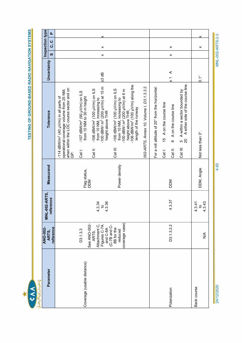
T
ESTI
NG
OF
GR
OU
ND
-BA
SED
RA
DIO
NA
VIG
ATI
ON
SYS
TEM
S
24/1
2/20
20
4
-50
MN
L-00
2-A
RTS
-2.0
Para
met
erA
NO
-002
-A
RTS
,re
fere
nce
MN
L-00
2-A
RTS
,re
fere
nce
Mea
sura
ndTo
lera
nce
Unce
rtai
nty
Insp
ectio
n ty
peS
C, C
P
Cov
erag
e (u
sabl
e di
stan
ce)
D3.
1.3.
3
See
ANO
-002
-AR
TS,
Atta
chm
ent C
,Fi
gure
s C
-7A
and
C-8
A(C
-7B
and
C-
8B fo
r the
redu
ced
cove
rage
cas
e)
4.3.
34to
4.3.
36
Flag
sta
tus,
DD
M
Pow
er d
ensi
ty
-114
dBW
/m2
(40
µV/m
) in
all p
arts
of
oper
atio
nal c
over
age
volu
me
from
25
NM
,w
hen
with
in th
e LO
C c
ours
e se
ctor
and
on
GP:
Cat
I:
-1
07 d
BW/m
2(9
0 µV
/m) o
n IL
Sfro
m 1
0 N
M to
30
m h
eigh
t
Cat
II:
-1
06 d
BW/m
2(1
00 µ
V/m
) on
ILS
from
10
NM
, inc
reas
ing
to-1
00 d
BW/ m
2(2
00 µ
V/m
) at 1
5 m
heig
ht a
bove
TH
R
Cat
III:
-1
06 d
BW/m
2(1
00 µ
V/m
) on
ILS
from
10
NM
, inc
reas
ing
to-1
00 d
BW/ m
2 (20
0 µV
/m) a
t 6 m
heig
ht a
bove
TH
R,
-106
dBW
/m2
(100
µV/
m) a
long
the
leng
th o
f the
runw
ay
002-
AR
TS, A
nnex
10,
Vol
ume
I, D
3.1.
3.3.
2.
±3 d
B x
xx
Pola
rizat
ion
D3.
1.3.
2.2
4.3.
37
DD
M
For a
roll
attit
ude
of 2
0° fr
om th
e ho
rizon
tal:
Cat
I:
15
A on
the
cour
se li
ne
Cat
II:
8
A on
the
cour
se li
ne
Cat
III:
5
A w
ithin
a s
ecto
r bou
nded
by
20A
eith
er s
ide
of th
e co
urse
line
.± 1
A x
x
Back
cou
rse
N/A
4.3.
41to
4.3.
43D
DM
, Ang
le
Not
less
than
3°.
0.1°
xx
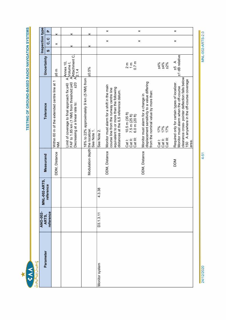
T
ESTI
NG
OF
GR
OU
ND
-BA
SED
RA
DIO
NA
VIG
ATI
ON
SYS
TEM
S
24/1
2/20
20
4
-51
MN
L-00
2-A
RTS
-2.0
Para
met
erA
NO
-002
-A
RTS
,re
fere
nce
MN
L-00
2-A
RTS
,re
fere
nce
Mea
sura
ndTo
lera
nce
Unce
rtai
nty
Insp
ectio
n ty
peS
C, C
P
DD
M, D
ista
nce
With
in 6
0 m
of t
he e
xten
ded
cent
re li
ne a
t 1N
M.
±6 m
xx
Lim
it of
cov
erag
e to
fina
l app
roac
h fix
:±40
AFA
F to
1.8
5 km
(1 N
M) f
rom
thre
shol
d:±4
0A
Dec
reas
ing
at a
line
ar ra
te to
:
±2
0A
Anne
x 10
,Vo
lum
e I,
Atta
chm
ent C
,2.
1.4
x x
Mod
ulat
ion
dept
h18
% to
22%
app
roxi
mat
ely
9 km
(5 N
M) f
rom
the
loca
lizer
.Se
e N
ote
1.±0
.5%
x x
Mon
itor s
yste
mD
3.1.
3.11
4.
3.38
DD
M, D
ista
nce
DD
M, D
ista
nce
DD
M
See
Not
e 2.
Mon
itor m
ust a
larm
for a
shi
ft in
the
mai
nco
urse
line
from
the
runw
ay c
entre
line
equi
vale
nt to
or m
ore
than
the
follo
win
gdi
stan
ces
at th
e IL
S re
fere
nce
datu
m.
Cat
I:
10
.5 m
(35
ft)C
at II
:
7.5
m (2
5 ft)
Cat
III:
6.
0 m
(20
ft)
Mon
itor m
ust a
larm
for a
cha
nge
indi
spla
cem
ent s
ensi
tivity
to a
val
ue d
iffer
ing
from
the
nom
inal
val
ue b
y m
ore
than
:
Cat
I:
17
%C
at II
:
17%
Cat
III:
17
%
Req
uire
d on
ly fo
r cer
tain
type
s of
loca
lizer
.M
onito
r mus
t ala
rm w
hen
the
off-c
ours
ecl
eara
nce
cros
s- p
oint
er d
efle
ctio
n fa
lls b
elow
150
A an
ywhe
re in
the
off-c
ours
e co
vera
gear
ea.
2 m
1 m
0.7
m
±4%
±4%
±2%
±5A
±1 d
B re
lativ
e
x x x
x x x
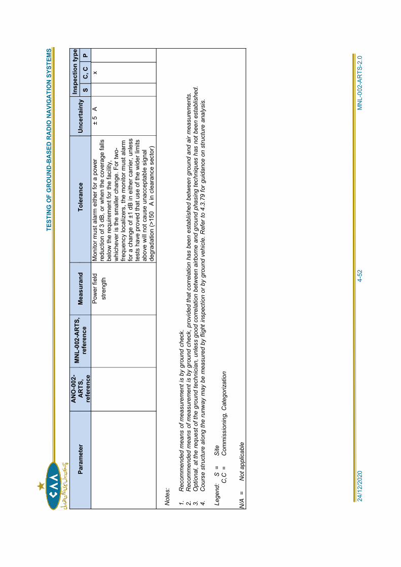
T
ESTI
NG
OF
GR
OU
ND
-BA
SED
RA
DIO
NA
VIG
ATI
ON
SYS
TEM
S
24/1
2/20
20
4
-52
MN
L-00
2-A
RTS
-2.0
Para
met
erA
NO
-002
-A
RTS
,re
fere
nce
MN
L-00
2-A
RTS
,re
fere
nce
Mea
sura
ndTo
lera
nce
Unce
rtai
nty
Insp
ectio
n ty
peS
C, C
PPo
wer
fiel
dst
reng
thM
onito
r mus
t ala
rm e
ither
for a
pow
erre
duct
ion
of 3
dB,
or w
hen
the
cove
rage
falls
belo
w th
e re
quire
men
t for
the
faci
lity,
whi
chev
er is
the
smal
ler c
hang
e. F
or tw
o-fre
quen
cy lo
caliz
ers,
the
mon
itor m
ust a
larm
for a
cha
nge
of ±
1 dB
in e
ither
car
rier,
unle
sste
sts
have
pro
ved
that
use
of t
he w
ider
lim
itsab
ove
will
not c
ause
una
ccep
tabl
e si
gnal
degr
adat
ion
(>15
0A
in c
lear
ance
sec
tor)
± 5
Ax
Not
es:
1.
Rec
omm
ende
d m
eans
of m
easu
rem
ent i
s by
gro
und
chec
k.2.
R
ecom
men
ded
mea
ns o
f mea
sure
men
t is
by g
roun
d ch
eck,
pro
vide
d th
at c
orre
latio
n ha
s be
en e
stab
lishe
d be
twee
n gr
ound
and
air
mea
sure
men
ts.
3.
Opt
iona
l, at
the
requ
est o
f the
gro
und
tech
nici
an, u
nles
s go
od c
orre
latio
n be
twee
n ai
rbor
ne a
nd g
roun
d ph
asin
g te
chni
ques
has
not
bee
n es
tabl
ishe
d.4.
C
ours
e st
ruct
ure
alon
g th
e ru
nway
may
be
mea
sure
d by
flig
ht in
spec
tion
or b
y gr
ound
veh
icle
. Ref
er to
4.3
.79
for g
uida
nce
on s
truct
ure
anal
ysis
.
Lege
nd:
S =
Site
C,C
=
C
omm
issi
onin
g, C
ateg
oriz
atio
n
N/A
=
N
ot a
pplic
able
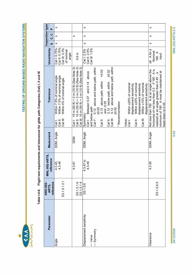
T
ESTI
NG
OF
GR
OU
ND
-BA
SED
RA
DIO
NA
VIG
ATI
ON
SYS
TEM
S
24/1
2/20
20
4
-53
MN
L-00
2-A
RTS
-2.0
Tabl
e I-4
-8.
Flig
ht te
st re
quire
men
ts a
nd to
lera
nces
for g
lide
path
Cat
egor
ies
(Cat
) I, I
I and
III
Para
met
erA
NO
-002
-A
RTS
,re
fere
nce
MN
L-00
2-A
RTS
,re
fere
nce
Mea
sura
ndTo
lera
nce
Unce
rtai
nty
Insp
ectio
n ty
peS
C, C
PAn
gle
D3.
1.5.
1.2.
1
4.3.
45,
4.3.
46D
DM
, Ang
le
Cat
I:
W
ithin
7.5
% o
f nom
inal
ang
leC
at II
:
With
in 7
.5%
of n
omin
al a
ngle
Cat
III:
W
ithin
4%
of n
omin
al a
ngle
Cat
I: 0
.75%
Cat
II: 0
.75%
Cat
III:
0.3%
of n
omin
alan
gle
x x
x
D3.
1.5.
1.6
D3.
1.5.
1.4
4.3.
81
DD
M
Cat
I:
15 m
(50
ft) +
3 m
(10
ft) (S
ee N
ote
3)C
at II
: 15
m (5
0 ft)
+ 3
m (1
0 ft)
(See
Not
e 3)
Cat
III:
15 m
(50
ft) +
3 m
(10
ft) (S
ee N
ote
3)0.
6 m
x
Dis
plac
emen
t sen
sitiv
ityD
3.1.
5.6
4.3.
47 to
4.3.
49D
DM
, Ang
le
Sym
met
ry:
Cat
I:
B
etw
een
0.07
and
0.1
4 a
bove
and
belo
w p
ath
Cat
I*:
0.
12 a
bove
and
bel
ow p
ath,
with
in±0
.02
Cat
II:
0
.12
abo
ve p
ath,
with
in
+0.
02
and
-0.0
5C
at II
:
0.1
2 b
elow
pat
h, w
ithin
±
0.02
Cat
III:
0
.12
abo
ve a
nd b
elow
pat
h, w
ithin
±0.0
2*
Rec
omm
enda
tion
Valu
e:C
at I:
With
in ±
25%
of n
omin
aldi
spla
cem
ent s
ensi
tivity
Cat
II:
W
ithin
±20
% o
f nom
inal
disp
lace
men
t sen
sitiv
ityC
at II
I:
With
in ±
15%
of n
omin
aldi
spla
cem
ent s
ensi
tivity
Cat
I: 2
.5%
Cat
II: 2
.0%
Cat
III:
1.5%
x x
x
Cle
aran
ce
D3.
1.5.
6.5
4.3.
50
DD
M, A
ngle
N
ot le
ss th
an 1
90A
at a
n an
gle
abov
e th
eho
rizon
tal o
f not
less
than
0.3
. If 1
90A
isre
aliz
ed a
t an
angl
e gr
eate
r tha
n 0.
45, a
min
imum
of 1
90A
mus
t be
mai
ntai
ned
atle
ast d
own
to 0
.45
.
±6A
for a
Nom
inal
190
Ain
put
x x
x
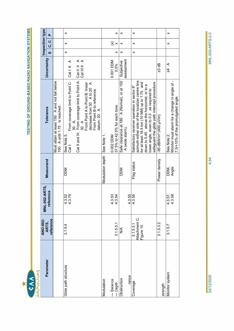
T
ESTI
NG
OF
GR
OU
ND
-BA
SED
RA
DIO
NA
VIG
ATI
ON
SYS
TEM
S
24/1
2/20
20
4
-54
MN
L-00
2-A
RTS
-2.0
Para
met
erA
NO
-002
-A
RTS
,re
fere
nce
MN
L-00
2-A
RTS
,re
fere
nce
Mea
sura
ndTo
lera
nce
Unce
rtai
nty
Insp
ectio
n ty
peS
C, C
PM
ust a
ttain
at l
east
150
A a
nd n
ot fa
ll be
low
150
A un
til 1
.75
is re
ache
d.
Glid
e pa
th s
truct
ure
3.1.
5.4
4.3.
524.
3.79
DD
M
See
Not
e 5.
Cat
I:
F
rom
cov
erag
e lim
it to
Poi
nt C
:30
A.C
at II
and
III:
Fro
m c
over
age
limit
to P
oint
A:
30A
F
rom
Poi
nt A
to P
oint
B: l
inea
rde
crea
se fr
om 3
0A
to 2
0A.
From
Poi
nt B
to re
fere
nce
datu
m: 2
0A.
Cat
I: 6
A
Cat
II: 4
AC
at II
I:4A
x x
x
Mod
ulat
ion
3.1.
5.5.
14.
3.53
4.3.
54
Mod
ulat
ion
dept
h Se
e N
ote
1.
0.00
2 D
DM
37.5
% to
42.
5% fo
r eac
h to
ne.
0.00
1 D
DM
0.5%
x(x
) xx
Obs
truct
ion
ranc
e
N/A
4.3.
55
DD
M
Safe
cle
aran
ce a
t 180
A (N
orm
al),
or a
t 150
A (w
ide
alar
m).
Subj
ectiv
eas
sess
men
tx
x x
Cov
erag
e3.
1.5.
3.1
Atta
chm
ent C
,Fi
gure
10
4.3.
56
Flag
sta
tus
Satis
fact
ory
rece
iver
ope
ratio
n in
sec
tor 8
°az
imut
h ei
ther
sid
e of
the
loca
lizer
cen
tre li
nefo
r at l
east
18.
5 km
(10
NM
) up
to 1
.75
and
dow
n to
0.4
5 a
bove
the
horiz
onta
l, or
to a
low
er a
ngle
, dow
n to
0.3
as
requ
ired
tosa
fegu
ard
the
glid
e pa
th in
terc
ept p
roce
dure
.
x
x x
stre
ngth
3.1.
5.3.
2Po
wer
den
sity
-9
5 dB
W/m
² (40
0 µV
/m)
±3 d
B
Mon
itor s
yste
m3.
1.5.
7 4.
3.57
,4.
3.58
DD
M,
Angl
eSe
e N
ote
2.M
onito
r mus
t ala
rm fo
r a c
hang
e in
ang
le o
f -7.
5/+1
0% o
f the
pro
mul
gate
d an
gle
±4A
x
x
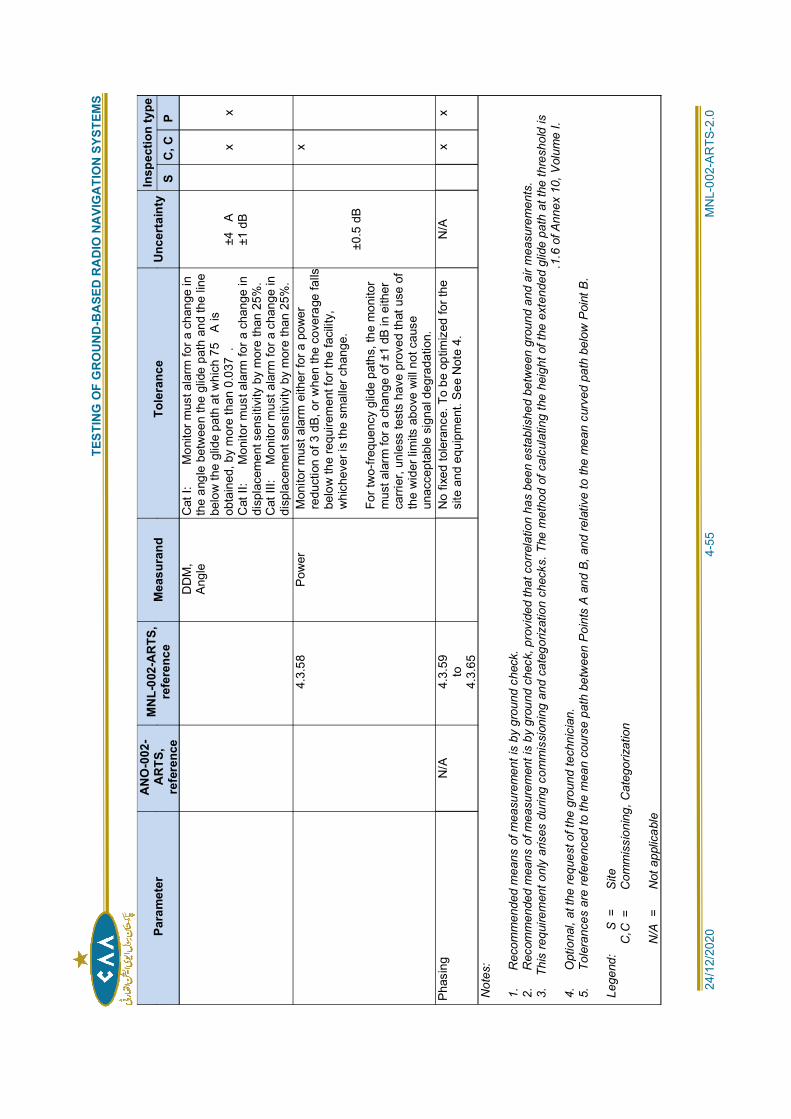
T
ESTI
NG
OF
GR
OU
ND
-BA
SED
RA
DIO
NA
VIG
ATI
ON
SYS
TEM
S
24/1
2/20
20
4
-55
MN
L-00
2-A
RTS
-2.0
Para
met
erA
NO
-002
-A
RTS
,re
fere
nce
MN
L-00
2-A
RTS
,re
fere
nce
Mea
sura
ndTo
lera
nce
Unce
rtai
nty
Insp
ectio
n ty
peS
C, C
PD
DM
,An
gle
Cat
I:
M
onito
r mus
t ala
rm fo
r a c
hang
e in
the
angl
e be
twee
n th
e gl
ide
path
and
the
line
belo
w th
e gl
ide
path
at w
hich
75
A is
obta
ined
, by
mor
e th
an 0
.037
.C
at II
:
Mon
itor m
ust a
larm
for a
cha
nge
indi
spla
cem
ent s
ensi
tivity
by
mor
e th
an 2
5%.
Cat
III:
M
onito
r mus
t ala
rm fo
r a c
hang
e in
disp
lace
men
t sen
sitiv
ity b
y m
ore
than
25%
.
±4A
±1 d
Bx
x
4.3.
58
Pow
er
Mon
itor m
ust a
larm
eith
er fo
r a p
ower
redu
ctio
n of
3 d
B, o
r whe
n th
e co
vera
ge fa
llsbe
low
the
requ
irem
ent f
or th
e fa
cilit
y,w
hich
ever
is th
e sm
alle
r cha
nge.
For t
wo-
frequ
ency
glid
e pa
ths,
the
mon
itor
mus
t ala
rm fo
r a c
hang
e of
±1
dB in
eith
erca
rrier
, unl
ess
test
s ha
ve p
rove
d th
at u
se o
fth
e w
ider
lim
its a
bove
will
not
cau
seun
acce
ptab
le s
igna
l deg
rada
tion.
±0.5
dB
x
Phas
ing
N/A
4.
3.59
to4.
3.65
No
fixed
tole
ranc
e. T
o be
opt
imiz
ed fo
r the
site
and
equ
ipm
ent.
See
Not
e 4.
N/A
x x
Not
es:
1.
Rec
omm
ende
d m
eans
of m
easu
rem
ent i
s by
gro
und
chec
k.2.
R
ecom
men
ded
mea
ns o
f mea
sure
men
t is
by g
roun
d ch
eck,
pro
vide
d th
at c
orre
latio
n ha
s be
en e
stab
lishe
d be
twee
n gr
ound
and
air
mea
sure
men
ts.
3.
This
requ
irem
ent o
nly
aris
es d
urin
g co
mm
issi
onin
g an
d ca
tego
rizat
ion
chec
ks. T
he m
etho
d of
cal
cula
ting
the
heig
ht o
f the
ext
ende
d gl
ide
path
at t
he th
resh
old
is.1
.6 o
f Ann
ex 1
0, V
olum
e I.
4.
Opt
iona
l, at
the
requ
est o
f the
gro
und
tech
nici
an.
5.
Tol
eran
ces
are
refe
renc
ed to
the
mea
n co
urse
pat
h be
twee
n P
oint
s A
and
B, a
nd re
lativ
e to
the
mea
n cu
rved
pat
h be
low
Poi
nt B
.
Lege
nd:
S
=
S
ite
C,C
=
C
omm
issi
onin
g, C
ateg
oriz
atio
n
N/A
=
N
ot a
pplic
able
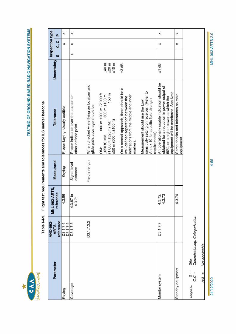
T
ESTI
NG
OF
GR
OU
ND
-BA
SED
RA
DIO
NA
VIG
ATI
ON
SYS
TEM
S
24/1
2/20
20
4
-56
MN
L-00
2-A
RTS
-2.0
Tabl
e I-4
-9.
Flig
ht te
st re
quire
men
ts a
nd to
lera
nces
for I
LS m
arke
r bea
cons
Para
met
erA
NO
-002
-A
RTS
,re
fere
nce
MN
L-00
2-A
RTS
,re
fere
nce
Mea
sura
ndTo
lera
nce
Unce
rtai
nty
Insp
ectio
n ty
pe
SC
, CP
Keyi
ng
D3.
1.7.
4D
3.1.
7.5
4.3.
66
Keyi
ng
Prop
er k
eyin
g, c
lear
ly a
udib
le
x x
Cov
erag
eD
3.1.
7.3
D3.
1.7.
3.2
4.3.
67 to
4.3.
71Si
gnal
leve
ldi
stan
ce
Fiel
d st
reng
th
Prop
er in
dica
tion
over
the
beac
on o
rot
her d
efin
ed p
oint
.
Whe
n ch
ecke
d w
hile
flyi
ng o
n lo
caliz
er a
ndgl
ide
path
, cov
erag
e sh
ould
be:
OM
:
6
00 m
±20
0 m
(2 0
00 ft
±650
ft) M
M:
300
m ±
100
m(1
000
ft ±
325
ft) IM
:
150
m±5
0 m
(500
ft ±
160
ft)
On
a no
rmal
app
roac
h, th
ere
shou
ld b
e a
wel
l-def
ined
sep
arat
ion
betw
een
the
indi
catio
ns fr
om th
e m
iddl
e an
d in
ner
mar
kers
.
Mea
sure
men
t sho
uld
use
the
Low
sens
itivi
ty s
ettin
g on
rece
iver
. (R
efer
toAn
nex
10 fo
r spe
cific
fiel
d st
reng
thre
quire
men
ts)
±40
m±2
0 m
±10
m
±3 d
B
x x
x
Mon
itor s
yste
m
D3.
1.7.
7 4.
3.72
,4.
3.73
An o
pera
tiona
lly u
sabl
e in
dica
tion
shou
ld b
eob
tain
ed fo
r a re
duct
ion
in p
ower
out
put o
f50
%, o
r a h
ighe
r pow
er a
t whi
ch th
eeq
uipm
ent w
ill be
mon
itore
d. S
ee N
ote.
±1 d
Bx
x
Stan
dby
equi
pmen
t
4.3.
74
S
ame
chec
ks a
nd to
lera
nces
as
mai
neq
uipm
ent.
x x
Lege
nd:
S
=
S
ite
C,C
=
C
omm
issi
onin
g, C
ateg
oriz
atio
n
N
/A =
Not
app
licab
le
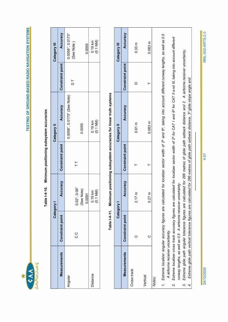
T
ESTI
NG
OF
GR
OU
ND
-BA
SED
RA
DIO
NA
VIG
ATI
ON
SYS
TEM
S
24/1
2/20
20
4
-57
MN
L-00
2-A
RTS
-2.0
Tabl
e I-4
-10.
M
inim
um p
ositi
onin
g su
bsys
tem
acc
urac
ies
Cat
egor
y I
Cat
egor
y II
Cat
egor
y III
Mea
sure
men
tsC
onst
rain
t poi
ntA
ccur
acy
Con
stra
int p
oint
Acc
urac
yC
onst
rain
t poi
ntA
ccur
acy
Angu
lar
C C
0.02
°, 0
.06°
(See
Not
e)0.
0091
T T
0.00
58°,
0.0
173°
(See
Not
e)
0.00
55
D T
0.00
58°,
0.0
173°
(See
Not
e )
0.00
55D
ista
nce
0.19
km
(0.1
NM
)0.
19 k
m(0
.1 N
M)
0.19
km
(0.1
NM
)
Tabl
e I-4
-11.
M
inim
um p
ositi
onin
g su
bsys
tem
acc
urac
ies
for l
inea
r tru
th s
yste
ms
Cat
egor
y I
Cat
egor
y II
Cat
egor
y III
Mea
sure
men
tsC
onst
rain
t poi
ntA
ccur
acy
Con
stra
int p
oint
Acc
urac
yC
onst
rain
t poi
ntA
ccur
acy
Cro
ss tr
ack
Verti
cal
C C
2.17
m
0.27
m
T T
0.61
m
0.08
3 m
D T
0.33
m
0.08
3 m
Not
es:
1.
Ext
rem
e lo
caliz
er a
ngul
ar a
ccur
acy
figur
es a
re c
alcu
late
d fo
r lo
caliz
er s
ecto
r w
idth
of
2º a
nd 6
º, ta
king
into
acc
ount
diff
eren
t run
way
leng
ths,
as
wel
l as
0.5
A a
irbor
ne re
ceiv
er u
ncer
tain
ty.
2.
Ext
rem
e lo
caliz
er c
ross
trac
k ac
cura
cy fi
gure
s ar
e ca
lcul
ated
for
loca
lizer
sec
tor
wid
th o
f 2º
for
CA
T I a
nd 6
º fo
r C
AT II
a n
d III
, tak
ing
into
acc
ount
diff
eren
tru
nway
leng
ths,
as
wel
l as
0.5
A a
irbor
ne re
ceiv
er u
ncer
tain
ty.
3.
Ext
rem
e gl
ide
path
ang
ular
tol
eran
ce f
igur
es a
re c
alcu
late
d fo
r 28
6 m
etre
s of
glid
e pa
th s
etba
ck d
ista
nce
and
2A
airb
orne
rece
iver
unc
erta
inty
.4.
E
xtre
me
glid
e pa
th v
ertic
al to
lera
nce
figur
es a
re c
alcu
late
d fo
r 286
met
res
of g
lide
path
set
back
dis
tanc
e, 3
º glid
e sl
ope
angl
e an
d__
____
____
____
____
____
____
____
TESTING OF GROUND-BASED RADIO NAVIGATION SYSTEMS
24/12/2020 5-1 MNL-002-ARTS-2.0
Chapter 5
NON-DIRECTIONAL BEACON (NDB)
5.1 INTRODUCTION:
SYSTEM DESCRIPTION:
5.1.1 A non-directional beacon (NDB) (also called a low- or medium-frequency homing beacon)transmits non-directional signals, primarily via ground wave propagation, whereby a pilot
operate on frequencies available in portions of the band between 190 and 1 750 kHzwith keyed identification and optional voice modulation. The airborne receiver installationis usually called an Automatic Direction Finder (ADF).
GROUND EQUIPMENT:
5.1.2 The ground equipment consists of a transmitter, antenna tuner and monitor, with optionalstandby transmitter, automatic changeover equipment and automatic antenna tuner. Themonitor is not always collocated with the transmitter equipment. The transmitternormally transmits a continuous carrier modulated by either 1 020 Hz or 400 Hz keyedto provide identification. In some special cases of high interference or noise levels, theunmodulated carrier is keyed instead. The transmitter power is selected to provide therequired minimum coverage, and varies from a few watts to several kilowatts. The antennasystem is a vertical radiator, commonly with top loading, with an extensive earth system toimprove efficiency and restrict high angle radiation.
AIRBORNE USER EQUIPMENT:
5.1.3 Airborne ADF equipment includes an omnidirectional sense antenna and a rotatable loop(or a fixed loop and a goniometer performing the same function). A continuous switchedphase comparison process between loop and sense antenna inputs resolves the 180-degree ambiguity that normally exists in the loop input. As part of this process, a servomotor (or electronics) drives the loop (or goniometer) to a balanced position dependentupon the direction of the signal source, and a corresponding synchronous azimuthindication is provided on the aircraft ADF bearing indicator instrument. The performance ofthe equipment may be degraded if the signal from the NDB is modulated by an audiofrequency equal or close to the loop switching frequency or its second harmonic.Loop switching frequencies are typically between 30 Hz and 120 Hz.
FACTORS AFFECTING NDB PERFORMANCE:
RATED COVERAGE:
5.1.4 The rated coverage of an NDB is an area in which a specified minimum signalstrength of the ground wave is obtained. Provided that an adequate value ofsignal strength is chosen, there is a high probability of obtaining accuratebearings in this area. However, since other factors (some of which are discussedbelow) determine whether accurate bearings are obtained, it is necessary tomeasure the quality of the bearings from the ADF during a flight check to assessthe effective coverage of the NDB.
FACTORS AFFECTING SIGNAL STRENGTH OF GROUND WAVE:
5.1.5 Antenna current. The signal strength obtained at any point throughout the ratedcoverage area is directly proportional to the current in the vertical radiator of theantenna. Doubling the antenna current will double the strength at a fixed point ordouble the range for a fixed value of signal strength. The power radiated isdependent on the antenna and ground system efficiency, which varies typically
TESTING OF GROUND-BASED RADIO NAVIGATION SYSTEMS
24/12/2020 5-2 MNL-002-ARTS-2.0
from 2 to 10 per cent. The power dissipated by the NDB transmitter is the sum ofthe powers radiated and dissipated by the ground system and ohmic losses.
5.1.6 Ground conductivity. The transmitter power necessary to drive a given currentthrough the antenna and ground system varies with the soil conductivity at theantenna site. The signal strength of the ground wave also depends on theconductivity of the soil between the transmitter and receiver. The conductivity ofseawater is higher than that of soil, hence the range over seawater is usuallygreater than over land.
5.1.7 Altitude. An increase in signal strength can be expected as the aircraft height isincreased, the effect being most marked over soil of poor conductivity, andalmost negligible over seawater.
FACTORS AFFECTING THE QUALITY AND ACCURACY OF ADF BEARINGS(EFFECTIVE COVERAGE):
5.1.8 Noise. The effective coverage is limited by the ratio of the strength of thesteady (non-fading) signal received from the NDB to the total noise interceptedby the ADF receiver. The noise admitted to the receiver depends on thebandwidth of the receiver, the level and characteristics of atmospheric noise inthe area together with noise sources in the aircraft and the level of theinterference produced by other radio emissions. If the signal-to-noise ratio is lessthan the limiting value, useful bearings cannot be obtained. In some cases, theeffective coverage may be limited to the range of a usable identification signal.
5.1.9 Night effect. The effective coverage of an NDB is also limited at night when askywave reflected from the ionosphere is present at the receiver in addition tothe vertically polarized ground wave on which the system depends during theday. The interaction of these two signals from the NDB results in bearing errorsin the ADF. The effect is independent of transmitter power.
5.1.10 Terrain effects. Errors in ADF bearings are often produced over rugged terrainor where abrupt discontinuities occur in the ground surface conductivity. Theeffect results in an oscillating bearing and usually diminishes with increasingaircraft altitude.
TESTING REQUIREMENTS:
5.1.11 A summary of testing requirements for NDB facilities is given in Table I-5-1
5.2 GROUND TESTING:
GENERAL:
5.2.1 The purpose of ground testing is to ensure that the NDB radiates a signal, which meetsthe requirements of Annex 10, Volume I, on a continuing basis. Since NDB equipmentvaries greatly, it is not possible to define detailed tests applicable to all types. Therefore,
recommendations for additional tests and detailed procedures for specific equipment.
GROUND PERFORMANCE PARAMETERS:
5.2.2 Ground test requirements are listed in Table I-5-2.
GROUND TEST PROCEDURES:
5.2.3 Carrier frequency. The carrier frequency should be checked against an accurate frequency
5.2.4 Antenna current. On most equipment, a meter is provided to read the current in theseries-resonant antenna system. (If not provided, an RF thermocouple-type ammeter
TESTING OF GROUND-BASED RADIO NAVIGATION SYSTEMS
24/12/2020 5-3 MNL-002-ARTS-2.0
should be temporarily inserted at ground potential in the series resonant antenna tunercircuit.) Any change in this current from its initial value at commissioning could be due to achange in the power delivered from the transmitter and/or a change in the characteristicsof the antenna system, including the transmission line and ground system. Changesshould be investigated, as the coverage performance of the beacon will be affected.
5.2.5 Modulation depth. The modulation depth can be measured by a modulation meter (which
instructions for detailed procedures for using a modulation meter. When using anoscilloscope, the modulated signal from the NDB (preferably obtained from a pick-upantenna) is displayed and the modulation depth obtained by measuring the maximum andminimum of the modulation envelope. (The radiated modulation percentage, as observedwith a pick-up antenna, may be reduced due to the high Q factor of the antenna system.) IfAmax and Amin are the maximum and minimum of the envelope respectively, then:
5.2.6 Modulation frequency. The modulation frequency should be measured using afrequency meter or a counter, or by comparison of the modulation frequency with that
instructions for the operation of these instruments.
5.2.7 Modulation depth of power supply frequency components. A monitor may be installed withsome NDB equipment to provide a means of detecting excessive power supply modulationon the carrier. A metering position is usually provided to enable this modulation depth tobe read for testing purposes. Alternatively, an oscilloscope can be used to display the NDBsignal (with identification modulation removed). By using a suitable time base frequency,modulation at the power supply frequency can be identified.
5.2.8 Spurious modulation components. The measurement of the modulation depth of spuriouscomponents on the carrier requires the use of a modulation meter or the modulationmeasuring circuits, which may be incorporated in the monitor. With the identificationmodulation removed, the residual modulation depth of the carrier is measured
5.2.9 Carrier level during modulation. A change in carrier level with modulation can be measuredusing a field intensity meter, modulation meter, carrier level meter on the monitor, or anoscilloscope. Using the first three methods, any change in the carrier level indication canbe noted by comparing the level with and without identification modulation. (Depending onthe detection and metering circuits used in these three methods, the bandwidth of theradio frequency circuits may need to be narrow enough to reject the modulationsidebands.) Using an oscilloscope, a pattern is displayed as described in 5.2.6 and theaverage carrier level with and without identification modulation is found. The carrier levelwithout modulation can be read directly from the screen, while the average level withmodulation is:
5.2.10 Audio frequency distortion. The design of the transmitting equipment will usually ensurethat modulation distortion is acceptably small. However, if a distorted signal is reported, ameasurement should be made of this parameter and appropriate action taken. The usualmeasuring equipment is a modulation monitor and distortion meter. Detailed procedures
5.2.11 Monitor system. The monitor system, when provided, should be checked to ensure it willdetect erroneous transmissions from the NDB. Some monitors include switching functionsthat permit fault conditions to be simulated. In other cases, NDB fault conditions should besimulated as closely as possible to check that the monitor will alarm. Detailed procedures
5.2.12 Reserved.
TESTING OF GROUND-BASED RADIO NAVIGATION SYSTEMS
24/12/2020 5-4 MNL-002-ARTS-2.0
TEST EQUIPMENT:
5.2.13 Test equipment list. The following test equipment is recommended for NDB groundmaintenance:
a) frequency meter, standard, or counter with an accuracy of at least 0.001 per cent(for carrier frequency);
b) RF thermocouple ammeter (if not part of the equipment), for measuring the antennacurrent;
c) distortion meter or wave analyser, for audio frequencies distortion;
d) frequency meter or standard frequency source with an accuracy of at least 0.5
be the same as used in a) above;
e) modulation meter or oscilloscope for modulation percentage measurements; and
f) field intensity meter where ground field strength measurements are to be made orwhere an airborne field strength installation is to be calibrated. The field intensitymeter can also be used to check for the radiation of spurious harmonics from theNDB
5.3 FLIGHT TESTING:
GENERAL:
5.3.1 The primary objectives of flight testing are to determine the coverage and quality of theguidance provided by the NDB system and to check for interference from other stations.These assessments are to be made in all areas where coverage is required and with alloperational procedures designed for the NDB, in order to determine the usability of thefacility and to ensure that it meets the operational requirements for which it was installed.However, this does not mean that the flight check aircraft must fly through the entirecoverage area, but rather, from a consideration of all the factors affecting the coverageand usability of the particular NDB, significant areas can be chosen for flightmeasurements from which the overall performance can be assessed. Such significantareas are typically at extreme range, along airways, in holding patterns, over mountains,etc.
FLIGHT TEST PERFORMANCE PARAMETERS:
5.3.2 Flight test requirements are listed in Table I-5-3.
FLIGHT TEST PROCEDURES:
IDENTIFICATION:
5.3.3 The coded identification on the NDB signal should be monitored during the flightinspection to the limit of coverage (in some cases, the range to which theidentification can be received may determine the effective coverage of the NDB).The identification is satisfactory if the coded characters are correct, clear, andproperly spaced. Monitoring of the identification during the flight also aids inidentifying an interfering station.
VOICE:
5.3.4 When a facility provides voice transmissions such as weather broadcasts, thevoice quality is checked. A voice transmission should be requested, if notavailable continuously, and a check made for quality, modulation and freedomfrom interference. If the voice transmission cannot be received at the maximum
TESTING OF GROUND-BASED RADIO NAVIGATION SYSTEMS
24/12/2020 5-5 MNL-002-ARTS-2.0
range from the beacon, the maximum range for satisfactory reception should benoted.
COVERAGE:
5.3.5 An NDB coverage is determined by field strength measurements (ratedcoverage) or by a quality assessment (effective coverage) of factors such assignal strength, voice and identification, and cross-pointer activity. The use ofeither or both methods depends upon operational and engineering requirements.
5.3.6 Co-channel interference. In areas where the density of NDB facilities is highand interference amongst them is likely, a night-time check should be made toverify that the design field strength is obtained at the rated coverage limit. If not,the transmitter power output should be adjusted accordingly. This will optimizethe power to minimize interference between NDBs.
5.3.7 Rated coverage. A representative orbit should be flown that demonstratesappropriate compliance to the rated coverage. If the terrain is consideredsufficiently homogeneous or if no problem areas are found such that acomplete orbit is unnecessary, the coverage can be probed via radial flight ormeasured in representative sectors by measuring the field strength alongsuitable airways, also at minimum altitude. Adjustments to the NDB antennacurrent may be required to obtain satisfactory results.
5.3.8 Field strength measurements. Field strength measurements are read from ameter or recorded along with DME distance or ground reference points. Thesereference points can then be plotted on a map together with the measured fieldstrength in order to arrive at the rated coverage. The measurements should bemade during daylight hours and in good weather conditions. If this is notpossible, the measurement conditions should be described in detail in the report.
5.3.9 Effective coverage. Effective coverage is obtained from an assessment ofthe quality of the guidance signals provided by the NDB. The areas where thequality is measured will be largely determined by the operational usage to bemade of the beacon and by a consideration of the factors affecting effectivecoverage described in 5.1.4 to 5.1.10. In most cases, it will be sufficient to fly theair routes served by the NDB together with a small radius orbit around thebeacon. However, where the effective coverage is required in all sectors, andcircumstances do not permit the coverage to be inferred from selected radials, anorbit commensurate with the required radius of coverage should be flown. Anyunusual areas within the required coverage area where the quality of the signalmay be affected, e.g. by mountains, should be flown. The flights should beconducted at minimum route or sector altitude and note made of excessive ADFneedle oscillation, weak identification or interference, together with DME distanceor ground reference points. These reference points can later be plotted on a mapto obtain the effective coverage and the location of areas of poor quality. Ifsuitable equipment is available, the ADF bearing from which the aircraft headinghas been subtracted can be recorded. Where interference occurs from anotherfacility, the interfering station should be identified.
AIRWAYS COVERAGE:
5.3.10 The facility coverage along the airways is obtained by flying the route atminimum altitude and checking for excessive ADF needle oscillation,identification quality and interference. Although all airways are checked at commissioning, it is usually not necessary to check all airways duringroutine tests. However, an airway in each quadrant should be checkedannually.
TESTING OF GROUND-BASED RADIO NAVIGATION SYSTEMS
24/12/2020 5-6 MNL-002-ARTS-2.0
HOLDING PATTERN AND APPROACH PROCEDURES:
5.3.11 Where a holding pattern or approach procedure is based on an NDB, this
is made for excessive needle oscillation, erroneous reversals giving a falseimpression of station passage, or any other unusual condition.
STATION PASSAGE:
5.3.12 This check confirms that a correct indication is given when passing over astation. The aircraft should be flown over the NDB, preferably from two radials90 degrees apart, to ensure that an ADF reversal is obtained with anacceptably limited needle oscillation.
STANDBY EQUIPMENT
5.3.13 The checks to be carried out on standby equipment (if installed) will depend onwhether it is identical to the main equipment. If the main and standby equipmentsare interchangeable, the full commissioning checks are carried out on oneequipment, and only the identification, voice, and a brief quality check on theother. Subsequent equipment operation can be scheduled so that routinechecks are carried out on each equipment alternately. If the standbyequipment is of lower power than the main, both equipments are checked duringcommissioning. This need not increase flight times if coordination betweenground and air can be arranged to change the equipment when requested.Thus, on a flight outbound on an airway from the NDB, the lower powerequipment is first checked, and when its coverage has been exceeded, thehigher power equipment is brought on and the flight proceeds to thecoverage limit of this equipment. If any change in the performance of the NDBis considered likely when connected to its source of standby power, then all theflight checks should be repeated with the NDB on standby power. Normally,facilities whose standby power source consists of float-charged batteries withoutswitching equipment do not require this check.
5.3.14 Reserved.
TEST EQUIPMENT:
5.3.15 The basic airborne equipment used for flight testing NDB facilities is a standardaircraft ADF receiver, calibrated to read field strength and bearing to the NDB.Continuous recording of the data derived from a flight check is highly desirable,and recordings of both field strength and the quality of the bearing information(needle swing) should be made, particularly at the time of commissioning. Avoltage proportional to the received signal strength usually can be obtained fromthe receiver, or field strength readings may be taken from a separate fieldstrength measuring equipment carried in the aircraft.
POSITIONING:
5.3.16 The quality of guidance given is usually judged by observing the needle swing ofthe ADF. However, it should be noted that since the ADF indicates the anglebetween the aircraft and the ground beacon, any yawing motion of the aircraftwill produce a swing in the ADF needle indication. Care should therefore betaken during a flight check to keep the aircraft heading as steady as possible.Alternatively, it has been found useful to record the
5.3.17 difference between the ADF bearing and the aircraft heading by means ofcomparing the ADF and compass outputs. In this way, the yawing motion of theaircraft is removed from the record. A typical formula used for this purpose is:
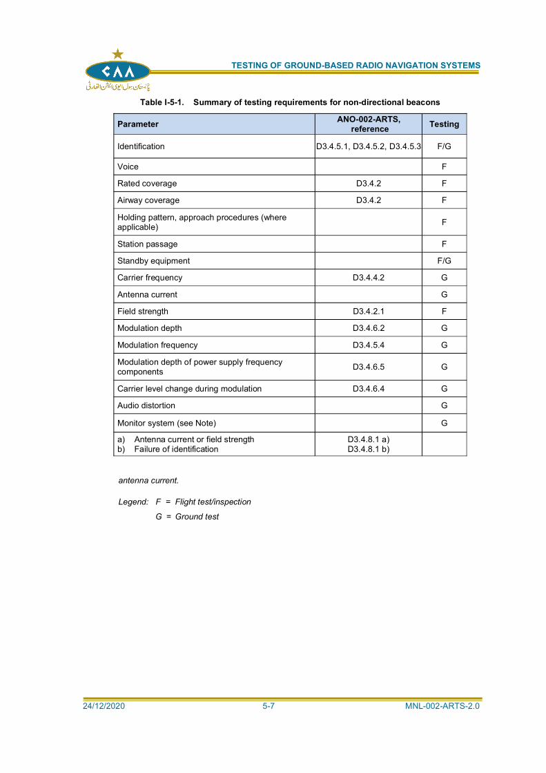
TESTING OF GROUND-BASED RADIO NAVIGATION SYSTEMS
24/12/2020 5-7 MNL-002-ARTS-2.0
Table I-5-1. Summary of testing requirements for non-directional beacons
Parameter ANO-002-ARTS, reference Testing
Identification D3.4.5.1, D3.4.5.2, D3.4.5.3 F/G
Voice F
Rated coverage D3.4.2 F
Airway coverage D3.4.2 F
Holding pattern, approach procedures (whereapplicable) F
Station passage F
Standby equipment F/G
Carrier frequency D3.4.4.2 G
Antenna current G
Field strength D3.4.2.1 F
Modulation depth D3.4.6.2 G
Modulation frequency D3.4.5.4 G
Modulation depth of power supply frequencycomponents D3.4.6.5 G
Carrier level change during modulation D3.4.6.4 G
Audio distortion G
Monitor system (see Note) G
a) Antenna current or field strengthb) Failure of identification
D3.4.8.1 a)D3.4.8.1 b)
antenna current.
Legend: F = Flight test/inspection
G = Ground test
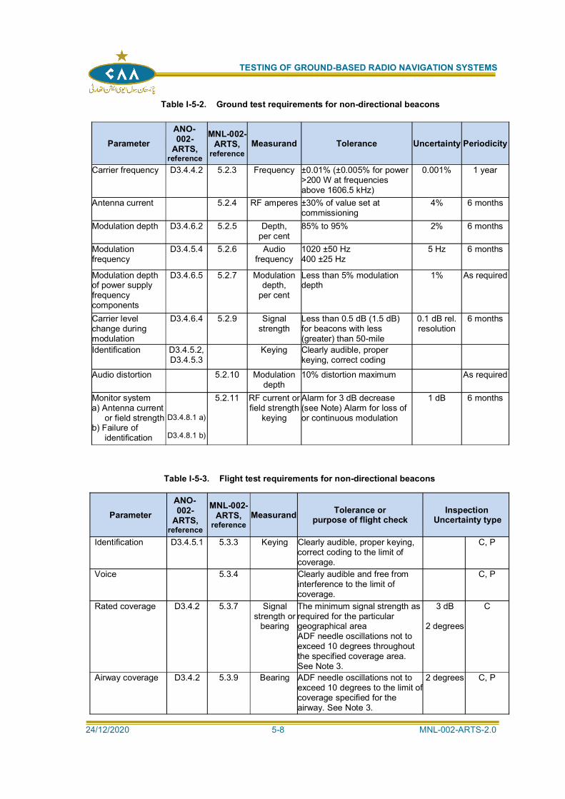
TESTING OF GROUND-BASED RADIO NAVIGATION SYSTEMS
24/12/2020 5-8 MNL-002-ARTS-2.0
Table I-5-2. Ground test requirements for non-directional beacons
ParameterANO-002-
ARTS,reference
MNL-002-ARTS,
referenceMeasurand Tolerance Uncertainty Periodicity
Carrier frequency D3.4.4.2 5.2.3 Frequency ±0.01% (±0.005% for power>200 W at frequenciesabove 1606.5 kHz)
0.001% 1 year
Antenna current 5.2.4 RF amperes ±30% of value set atcommissioning
4% 6 months
Modulation depth D3.4.6.2 5.2.5 Depth,per cent
85% to 95% 2% 6 months
Modulationfrequency
D3.4.5.4 5.2.6 Audiofrequency
1020 ±50 Hz400 ±25 Hz
5 Hz 6 months
Modulation depthof power supplyfrequencycomponents
D3.4.6.5 5.2.7 Modulationdepth,
per cent
Less than 5% modulationdepth
1% As required
Carrier levelchange duringmodulation
D3.4.6.4 5.2.9 Signalstrength
Less than 0.5 dB (1.5 dB)for beacons with less(greater) than 50-mile
0.1 dB rel.resolution
6 months
Identification D3.4.5.2,D3.4.5.3
Keying Clearly audible, properkeying, correct coding
Audio distortion 5.2.10 Modulationdepth
10% distortion maximum As required
Monitor systema) Antenna current
or field strengthb) Failure of
identification
D3.4.8.1 a)
D3.4.8.1 b)
5.2.11 RF current orfield strength
keying
Alarm for 3 dB decrease(see Note) Alarm for loss ofor continuous modulation
1 dB 6 months
Table I-5-3. Flight test requirements for non-directional beacons
ParameterANO-002-
ARTS,reference
MNL-002-ARTS,
referenceMeasurand Tolerance or
purpose of flight checkInspection
Uncertainty type
Identification D3.4.5.1 5.3.3 Keying Clearly audible, proper keying,correct coding to the limit ofcoverage.
C, P
Voice 5.3.4 Clearly audible and free frominterference to the limit ofcoverage.
C, P
Rated coverage D3.4.2 5.3.7 Signalstrength or
bearing
The minimum signal strength asrequired for the particulargeographical areaADF needle oscillations not toexceed 10 degrees throughoutthe specified coverage area.See Note 3.
3 dB
2 degrees
C
Airway coverage D3.4.2 5.3.9 Bearing ADF needle oscillations not toexceed 10 degrees to the limit ofcoverage specified for theairway. See Note 3.
2 degrees C, P
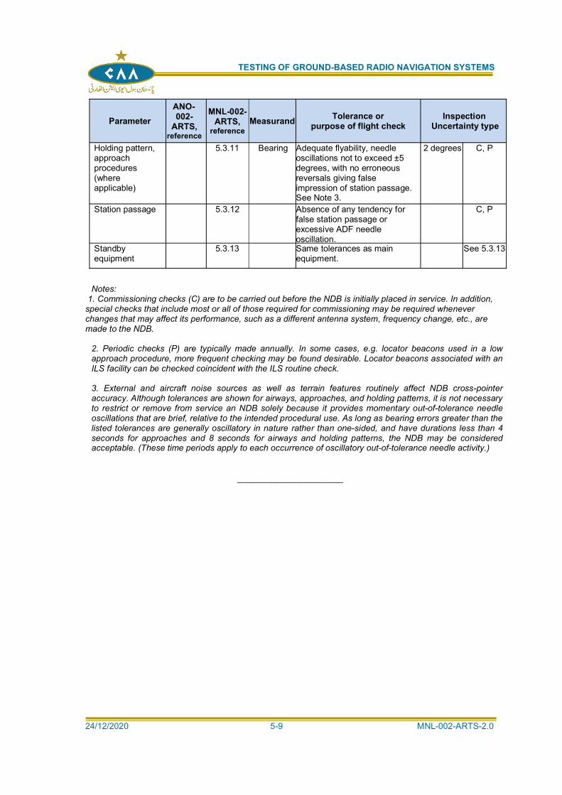
TESTING OF GROUND-BASED RADIO NAVIGATION SYSTEMS
24/12/2020 5-9 MNL-002-ARTS-2.0
ParameterANO-002-
ARTS,reference
MNL-002-ARTS,
referenceMeasurand Tolerance or
purpose of flight checkInspection
Uncertainty type
Holding pattern,approachprocedures(whereapplicable)
5.3.11 Bearing Adequate flyability, needleoscillations not to exceed ±5degrees, with no erroneousreversals giving falseimpression of station passage.See Note 3.
2 degrees C, P
Station passage 5.3.12 Absence of any tendency forfalse station passage orexcessive ADF needleoscillation.
C, P
Standbyequipment
5.3.13 Same tolerances as mainequipment.
See 5.3.13
Notes: 1. Commissioning checks (C) are to be carried out before the NDB is initially placed in service. In addition,special checks that include most or all of those required for commissioning may be required wheneverchanges that may affect its performance, such as a different antenna system, frequency change, etc., aremade to the NDB.
2. Periodic checks (P) are typically made annually. In some cases, e.g. locator beacons used in a lowapproach procedure, more frequent checking may be found desirable. Locator beacons associated with anILS facility can be checked coincident with the ILS routine check.
3. External and aircraft noise sources as well as terrain features routinely affect NDB cross-pointeraccuracy. Although tolerances are shown for airways, approaches, and holding patterns, it is not necessaryto restrict or remove from service an NDB solely because it provides momentary out-of-tolerance needleoscillations that are brief, relative to the intended procedural use. As long as bearing errors greater than thelisted tolerances are generally oscillatory in nature rather than one-sided, and have durations less than 4seconds for approaches and 8 seconds for airways and holding patterns, the NDB may be consideredacceptable. (These time periods apply to each occurrence of oscillatory out-of-tolerance needle activity.)
______________________

TESTING OF GROUND-BASED RADIO NAVIGATION SYSTEMS
24/12/2020 5-10 MNL-002-ARTS-2.0
INTENTIONALLY LEFT BLANK
TESTING OF GROUND-BASED RADIO NAVIGATION SYSTEMS
24/12/2020 6-1 MNL-002-ARTS-2.0
Chapter 6
EN-ROUTE VHF MARKER BEACONS (75 MHz)
6.1 INTRODUCTION:
SYSTEM DESCRIPTION:
6.1.1 En-route marker beacons identify a particular location along an airway and are generallyassociated with low frequency and VHF radio ranges. A 75 MHz signal modulated by 3000 Hz is radiated from the ground equipment in a narrow beam directed upwards. This isreceived by aircraft flying overhead and an audible and visible indication is given to thepilot. On some beacons, the modulating tone is keyed to provide identification coding. Twotypes of en-route marker beacons are in general use. Fan or F markers are used toidentify locations along airways, have an approximately elliptical coverage shape at agiven altitude, and are generally located some distance from the navigation aid definingthe airway. Station location or Z markers are used to identify the location of a navigationaid on an airway, have an approximately circular coverage at a given altitude, and areinstalled close to the station.
GROUND EQUIPMENT:
6.1.2 The ground equipment consists of a 75 MHz transmitter, an antenna system usuallyconsisting of a dipole or array of dipoles over an elevated counterpoise, and, in the usualcase, a monitor to detect out-of-tolerance conditions. The transmitter generates acontinuous carrier amplitude modulated approximately 95 per cent by a 3 000 Hz tone.The modulating tone may be keyed with dots and dashes to provide coded identification.Since the marker system depends on the measurement of a radio frequency signal level
AIRBORNE USER EQUIPMENT:
6.1.3 Airborne marker beacon systems consist of antenna, receiver, and indicatorsubsystems. The antenna may be a standard open wire or a flush mounted type, and is
by headset or speaker, and is also passed through an appropriate filter (3 000 Hz for en-route markers) to operate a white lamp. This lamp is usually one of a three-lampinstallation, the other two responding to ILS marker beacon signals. The sensitivity of thereceiver and antenna combination is adjusted so that the indicator lamp illuminates whenthe signal level reaches a specified level.
6.1.4 Reserved.
TESTING REQUIREMENTS:
6.1.5 A summary of testing requirements for en-route marker beacons is given in Table I-6-1
6.2 GROUND TESTING:
GENERAL:
6.2.1 The purpose of ground testing is to ensure that the marker beacon radiates a signal thatmeets the requirements of ANO-002-ARTS, on a continuous basis. Since markerequipment varies greatly, it is not possible to define detailed tests applicable to all types.Therefore, only a high-level description of the tests will be provided. Refer to a
equipment.
TESTING OF GROUND-BASED RADIO NAVIGATION SYSTEMS
24/12/2020 6-2 MNL-002-ARTS-2.0
GROUND PERFORMANCE PARAMETERS:
6.2.2 Ground test requirements are listed Table I-6-2.
GROUND TEST PROCEDURES:
6.2.3 Carrier frequency. The carrier frequency should be checked using an accuratefrequency standard to ensure that it is within tolerance. Refer to the instructions suppliedwith the frequency standard for detailed procedures.
6.2.4 RF output power. Since the power output of the transmitter directly affects the coverage, itis important to maintain the power as close as possible to the commissioning value. Onmost equipment a meter is provided and may be confirmed by using an independentpower output meter.
6.2.5 Modulation depth. Modulation depth can be measured using a modulation meter (it maybe built into the equipment) or by an oscilloscope. Using an oscilloscope, the modulatedsignal from the beacon is displayed (usually by direct connection to the deflection plates)and the modulation percentage obtained by measuring the maximum and minimum of themodulation envelope. If Amax and Amin are the maximum and minimum of the enveloperespectively, then:
modulation meter.
6.2.6 Modulation frequency. The modulation frequency can be measured using a frequencymeter or by comparing the frequency with an accurate (0.5 per cent) audio generator.
6.2.7 Harmonic content of modulation. The design of the transmitting equipment will usuallyensure that modulation distortion is acceptably small. However, if a distorted signal isreported, a measurement should be made of this parameter and appropriate action taken.The usual measuring equipment is a modulation monitor and distortion meter.
6.2.8 Identification keying. If identification keying is used on the marker beacon, an audibleindication is usually available from a test point on the equipment or monitor to audiblycheck for clear, correct keying.
6.2.9 Monitor system. The monitor system, when provided, should be checked to ensure that itwill detect erroneous transmissions from the marker beacon. Some monitors includeswitching functions, which permit faulty conditions to be simulated. Detailed procedures
tolerance conditions should be simulated, as closely as possible, to check that the monitorwill alarm.
6.2.10 Reserved.
TEST EQUIPMENT:
6.2.11 Test equipment list. The following test equipment is recommended for marker beaconground maintenance:
a) frequency meter covering the 75 MHz band with an accuracy of at least 0.004 percent;
TESTING OF GROUND-BASED RADIO NAVIGATION SYSTEMS
24/12/2020 6-3 MNL-002-ARTS-2.0
b) frequency meter or standard frequency source with an accuracy of at least 0.5
the same as that used in a) above;
c) modulation meter or oscilloscope for modulation percentage measurement;
d) wave analyser for harmonic distortion measurements; and
e) RF power meter.
6.3 FLIGHT TESTING:
GENERAL:
visual indication is within operational tolerances. This may be found by noting when thelamp is illuminated, by a calibrated marker receiver or by measuring the signal level fromthe marker beacon antenna.
FLIGHT TEST PERFORMANCE PARAMETERS:
6.3.2 Flight testing requirements are listed in Table I-6-3.
FLIGHT TEST PROCEDURES:
IDENTIFICATION CODING:
6.3.3 If identification coding is used on the marker beacon, it should be checkedduring a flight over the beacon. The identification is assessed from both theaural and visual indications and is satisfactory when the coded characters arecorrect, clear and properly spaced. The frequency of the modulating tone canbe checked by observing that the visual indication is obtained on the correct(white) lamp of a three-lamp system.
COVERAGE:
GENERAL:
6.3.4 There is no international Standard for coverage of an en-route marker.It is determined by operational requirements. Coverage is measured byflying over the marker beacon at operationally used altitudes and bymeasuring the total time or distance during which a visual indication isobtained from a calibrated marker receiver and antenna, or duringwhich a predetermined signal level is obtained. At commissioning, thecoverage should be measured at a number of altitudes, while forroutine checks it will usually be sufficient to make the check at a singlealtitude. Since the routine checks of the marker beacon will normally becarried out in conjunction with the associated navigation aid, it will beconvenient to check both at the same altitude. At commissioning, it ispreferable to determine the coverage by making a continuousrecording of signal strength, since this allows a more detailedassessment of the ground beacon performance. For routine checks,measurement of light activation time or distance over which the visualindication is received will usually be sufficient.
MEASURING PROCEDURE:
6.3.5 The procedure used for coverage measurements is to fly over thebeacon, noting the true air speed of the aircraft and the total time ordistance over which the visual indication or predetermined signallevel is obtained. A 180-degree turn is then made and themeasurement repeated while flying over the beacon at the same air

TESTING OF GROUND-BASED RADIO NAVIGATION SYSTEMS
24/12/2020 6-4 MNL-002-ARTS-2.0
speed in the opposite direction. These two flights are required in orderto average out the wind speed and other effects, such as receiver lag,tilt, or asymmetry in aircraft antenna pattern, etc. The time duringwhich visual indication is obtained (light time) can be measured directlyby a stopwatch. If a continuous recording of a signal level is beingmade, a knowledge of the chart speed will enable the time for whichthe predetermined value of the signal level is exceeded to be scaleddirectly from the chart. The coverage may be converted into time at areference air speed or distance as follows:
If V1 is the true air speed and T1, T2 are the coverage times obtainedon the two flights in opposite directions, then the coverage time, T, at areference air speed of V2 and coverage distance, D, will be:
6.3.6 Alternatively, coverage distance may be measured directly by flyingover the beacon as described above, and noting the locations on theground directly beneath the aircraft which coincide with the beginningand end of marker lights on. These points defining the coverage areaare then plotted on a map of the locality and the coverage distanceread off. If the flight check aircraft is fitted with a positioning system, itcan be used to measure the coverage area. A DME, suitably located,could also be used.
6.3.7 At commissioning, a check should be made that the centre of thecoverage area is in the correct position. This will usually be over themarker beacon but in some cases, due to siting difficulties, the polaraxis of the marker beacon radiation pattern may have to be other thanvertical. Reference should then be made to the operational proceduresto determine the correct location of the centre of coverage, withrespect to some recognizable point on the ground. The centre ofcoverage can be checked during the coverage flights described above,by marking the continuous recording when the aircraft is directly overthe marker beacon (or other defined point). The average of the tworecordings, taken with respect to the mark on the recording, will showwhether the coverage pattern is centred over the beacon (or otherdefined point). The separate recordings taken in each direction willseldom be symmetrical about this reference mark on the recordingdue to such effects as asymmetry of ground beacon radiationpattern, tilt in aircraft antenna pattern, receiver lags, etc.
STANDBY EQUIPMENT (IF INSTALLED):
6.3.8 At commissioning, the standby equipment is checked in the same manner as themain equipment. For routine checks, it is usually not necessary to check bothmain and standby equipment, provided that the checks are carried out on eachpiece of equipment alternately. If any change in the performance of the markerbeacon is considered likely when it is connected to its source of standby power,then all the flight checks should be repeated with the marker beacon on standbypower.
6.3.9 Reserved.
TEST EQUIPMENT:
DESCRIPTION OF AIRBORNE FLIGHT INSPECTION EQUIPMENT
6.3.10 The airborne equipment used for the flight inspection of marker beacons is
TESTING OF GROUND-BASED RADIO NAVIGATION SYSTEMS
24/12/2020 6-5 MNL-002-ARTS-2.0
usually a standard aircraft marker receiver and antenna. It is highly desirable,particularly for commissioning, to have the receiver modified so that the fieldstrength can be continuously recorded. Alternatively, a suitable generalpurpose field strength meter covering the 75 MHz band could be used. Thesignal level used for calibration of the airborne marker receiver or field strengthmeter depends on the type of aircraft antenna used.
6.3.11 The standard open-wire antenna referred to in this chapter is a half-wave dipolemounted 15 cm (6 inches) below the approximate centre line of the metallicfuselage with its axis parallel to the longitudinal axis of the aircraft and clearedfrom any other antennas or projections by at least one metre. The lead-inconsists of a wire connecting the antenna 13 cm (5 inches) off-centre to a 70ohm concentric transmission line. The lead-in connects to the transmission linewithin 5 cm (2 inches) of the fuselage skin inside the aircraft.
CALIBRATION:
6.3.12 When the marker beacon receiver is used with the standard open-wire antenna,the receiver sensitivity is adjusted so that the lamp is illuminated for an inputsignal level of 1 000 microvolts, 3 000 Hz modulated at 95 per cent. The lampshould be extinguished (50 per cent of lamp voltage or less) when the inputsignal is reduced to 800 microvolts. These signal levels are the open circuitvoltages from a generator with a source impedance of 50 ohms. To ensurerepeatable results, it is important that the input impedance of the markerreceiver be resistive and between 50 and 100 ohms. If an antenna otherthan the above standard is used, a figure should be obtained from themanufacturer which relates its gain to that of the standard open-wireantenna. This same factor is then applied to the receiver sensitivityadjustment. For example, if the antenna gain is 3 dB relative to the standardopen wire, then the receiver should be adjusted so that the lamp isilluminated for an input of 700 microvolts and extinguished for an input of570 microvolts. The antenna should be adjusted in accordance with the
6.3.13 When the coverage is determined by measuring the signal level from theaircraft antenna, the coverage limits are defined by the 1 000 microvoltcontour if the standard open wire antenna is employed. If another type ofaircraft antenna is used, the equivalent signal level for coverage measurementis determined in the same manner described above for the receiver and lampcalibration.
6.3.14 Airborne test equipment uncertainty. The tolerance for the coverageperformance of a marker beacon is ±5 s compared to a 20 s nominal value, or25 per cent relative. When applied to the allowable variation of the signal, thistolerance corresponds to:
Because the test equipment tolerances should be at least five times betterthan the parameter to be measured, the uncertainty on measuring the inputsignal level is 10 V.
POSITIONING:
6.3.15 Minimum requirements. Flight inspection of the signal characteristics of the 75 MHzen-route marker beacon does not require reference positioning of the aircraft.Tolerances are given in time units, requiring that the aircraft fly on a defined trajectoryand at a constant ground speed. Nominal values are a ground speed of 220 km/hr(120 kt) or 60 m/s, and an altitude of 600 m (2 000 ft) or as determined from operationalrequirements.
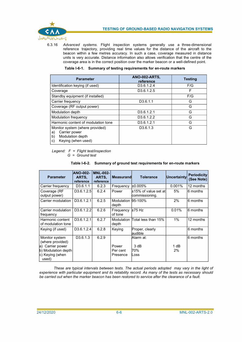
TESTING OF GROUND-BASED RADIO NAVIGATION SYSTEMS
24/12/2020 6-6 MNL-002-ARTS-2.0
6.3.16 Advanced systems. Flight inspection systems generally use a three-dimensionalreference trajectory, providing real time values for the distance of the aircraft to thebeacon within a few metres accuracy. In such a case, coverage measured in distanceunits is very accurate. Distance information also allows verification that the centre of thecoverage area is in the correct position over the marker beacon or a well-defined point.
Table I-6-1. Summary of testing requirements for en-route markers
Parameter ANO-002-ARTS,reference Testing
Identification keying (if used) D3.6.1.2.4 F/GCoverage D3.6.1.2.5 FStandby equipment (if installed) F/GCarrier frequency D3.6.1.1 GCoverage (RF output power) GModulation depth D3.6.1.2.1 GModulation frequency D3.6.1.2.2 GHarmonic content of modulation tone D3.6.1.2.1 GMonitor system (where provided)a) Carrier powerb) Modulation depthc) Keying (when used)
D3.6.1.3 G
Legend: F = Flight test/inspection G = Ground test
Table I-6-2. Summary of ground test requirements for en-route markers
ParameterANO-002-
ARTS,reference
MNL-002-ARTS,
referenceMeasurand Tolerance Uncertainty Periodicity
(See Note)
Carrier frequency D3.6.1.1 6.2.3 Frequency ±0.005% 0.001% 12 monthsCoverage (RFoutput power)
D3.6.1.2.5 6.2.4 Power ±15% of value set atcommissioning.
5% 6 months
Carrier modulation D3.6.1.2.1 6.2.5 Modulationdepth
95-100% 2% 6 months
Carrier modulationfrequency
D3.6.1.2.2 6.2.6 Frequencyof tone
±75 Hz 0.01% 6 months
Harmonic contentof modulation tone
D3.6.1.2.1 6.2.7 Modulationdepth
Total less than 15% 1% 12 months
Keying (if used) D3.6.1.2.4 6.2.8 Keying Proper, clearlyaudible
6 months
Monitor system(where provided)
a) Carrier powerb) Modulation depthc) Keying (when
used)
D3.6.1.3 6.2.9
PowerPer centPresence
Alarm at:
3 dB70%Loss
1 dB2%
6 months
These are typical intervals between tests. The actual periods adopted may vary in the light ofexperience with particular equipment and its reliability record. As many of the tests as necessary shouldbe carried out when the marker beacon has been restored to service after the clearance of a fault.
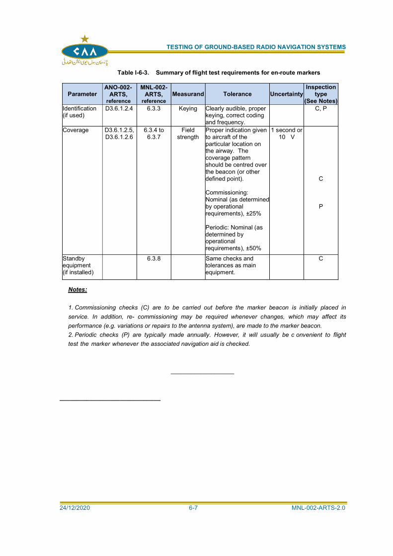
TESTING OF GROUND-BASED RADIO NAVIGATION SYSTEMS
24/12/2020 6-7 MNL-002-ARTS-2.0
Table I-6-3. Summary of flight test requirements for en-route markers
ParameterANO-002-
ARTS,reference
MNL-002-ARTS,
referenceMeasurand Tolerance Uncertainty
Inspectiontype
(See Notes)Identification(if used)
D3.6.1.2.4 6.3.3 Keying Clearly audible, properkeying, correct codingand frequency.
C, P
Coverage D3.6.1.2.5,D3.6.1.2.6
6.3.4 to6.3.7
Fieldstrength
Proper indication givento aircraft of theparticular location onthe airway. Thecoverage patternshould be centred overthe beacon (or otherdefined point).
Commissioning:Nominal (as determinedby operationalrequirements), ±25%
Periodic: Nominal (asdetermined byoperationalrequirements), ±50%
1 second or10 V
C
P
Standbyequipment(if installed)
6.3.8 Same checks andtolerances as mainequipment.
C
Notes:
1. Commissioning checks (C) are to be carried out before the marker beacon is initially placed inservice. In addition, re- commissioning may be required whenever changes, which may affect itsperformance (e.g. variations or repairs to the antenna system), are made to the marker beacon.2. Periodic checks (P) are typically made annually. However, it will usually be c onvenient to flighttest the marker whenever the associated navigation aid is checked.
___________________
______________________________
TESTING OF GROUND-BASED RADIO NAVIGATION SYSTEMS
24/12/2020 7-1 MNL-002-ARTS-2.0
Chapter 7
PRECISION APPROACH RADAR (PAR)
7.1 INTRODUCTION:
SYSTEM DESCRIPTION:
7.1.1 Precision approach radar (PAR) is the part of the precision approach radar system thatprovides the range, azimuth and elevation data when the aircraft is in the final stages ofapproach. The surveillance radar element (SRE), when installed, provides the orientationinformation required to direct the aircraft to the correct position and altitude so that thefinal approach can be instituted.
7.1.2 PAR is designed to provide an approach path for precise alignment and descentguidance to an aircraft on final approach to a specific runway, through the interpretationand oral instructions of a ground-based controller. PARs provide a very high degree ofresolution in terms of range, azimuth and elevation by radiating a narrow pulse andbeamwidth. Target information is displayed on an azimuth and elevation display. The
elevation angle.
EQUIPMENT DESCRIPTION:
7.1.3 The PAR is a pulsed radar system employing two antennas that scan in a narrowsector, one in the azimuth plane and the other in the elevation plane. Systems can beanalogue-based with single transmitter/receiver combinations feeding cathode ray tubesor more complex digital systems with phased array antennas and digital displays.
7.1.4 The transmitting equipment transmits pulsed RF energy at frequencies in the order of 9000 MHz. The pulsed beams are radiated along the predetermined descent path by theazimuth and elevation antennas for an approximate range of 18.5 km (10 NM), and cancover sectors of up to 20 degrees (10 degrees nominally) in azimuth and 7 degrees(from 1 to 6 degrees) in elevation. Dual transmitter/receivers are provided at most PARinstallations to increase the reliability of the system.
7.1.5 For older analogue systems the PAR shelter may be designed specifically to house thetwo antennas and the electronic equipment, and is often mounted on a turntable locatedadjacent to intersecting runways to permit multiple coverage. Digital PARs may house thephased array antenna in one enclosure and the equipment in a separate one.
7.1.6 The display console of the PAR is generally located in a control tower or approach room.The video and control signals are transmitted between these two sites by the use ofappropriate cables, either using analogue or digital techniques.
7.1.7 The PAR operator obtains the azimuth, elevation and distance information from the radardisplay and, through radiotelephone contact, provides guidance to the pilot so that acorrect approach
AIRBORNE USER EQUIPMENT:
7.1.8 There is no airborne equipment requirement for PAR to generate guidance informationfor the controller as the ground equipment relies on passive signals reflected from theaircraft skin. To use PAR, radio communication with air traffic control on the designatedfrequency at the airport is required.
FACTORS AFFECTING PAR PERFORMANCE:
7.1.9 The PAR employs directive scanning antenna systems, which do not rely on ground
TESTING OF GROUND-BASED RADIO NAVIGATION SYSTEMS
24/12/2020 7-2 MNL-002-ARTS-2.0
reflections in the formation of the radiation pattern. However, the condition of the terrainnear the PAR can affect signal accuracy as with some other navigational facilities due toreflected multipath. Furthermore, the surrounding terrain is an important factor, as aground reflection or a shadow effect can also create loss-of-aircraft-return in theground clutter on the display or loss of line-of-sight to the aircraft.
7.1.10 The accuracy of the PAR depends significantly on the equipment design as it affectsthe read-out resolution of azimuth, elevation and distance. In addition, the ability of theradar to distinguish between two targets in close proximity is of prime importance.Similarly, the size of the displayed return on the display will affect the ability of the
settings chosen by the controller, such as rain/ground clutter filters and, for digitalsystems, the setting of the target size.
7.1.11 The flight testing and calibration of the PAR is of prime importance to the quality of thePAR. Great care should be taken during flight testing, and subsequent maintenance andadjustment on a regular basis should be such as to assure continued accurate operation.
TESTING REQUIREMENTS:
7.1.12 A summary of testing requirements is given in Table I-7-1.
7.2 GROUND TESTING:
GENERAL:
7.2.1 While this chapter outlines certain scheduled tests, which should form part of themaintenance routine, the need for non-scheduled maintenance due to failure or tosuspected deterioration will periodically occur. Regular and conscientious scheduledmaintenance will ensure the high level of availability required of the system andminimize non-scheduled maintenance.
7.2.2 Since the operation of the PAR involves an air traffic controller, it is important that thisperson be satisfied and confident in the operational validity of the equipmentperformance. Should conflict exist between the technical criteria and operationalconfidence, prompt action should always be taken to verify the system and resolvequestionable factors.
GROUND PERFORMANCE PARAMETERS:
7.2.3 Ground testing of a PAR requires that certain tests be done periodically. Thefollowing text presents general performance tests that may be used. These should be
experience with the specific equipment being maintained. Note the tests are specifiedfor analogue systems. Manufacturer recommendations should be followed for moderndigital PAR systems.
GROUND TEST PROCEDURES:
GENERAL:
7.2.4 The ground test procedures described here are in general terms for analogue
equipment manuals and will tend to vary considerably with the equipmentbeing tested.
PROCEDURES (ANALOGUE SYSTEMS ONLY):
7.2.5 Panel meter readings. The equipment is usually provided with front panelmeters or computerized read-outs that allow regular checking of powersupply and other voltages, as well as selected current figures forimportant circuits. These readings should be recorded and analysed todetect gradual changes in circuit performance and indications of possible
TESTING OF GROUND-BASED RADIO NAVIGATION SYSTEMS
24/12/2020 7-3 MNL-002-ARTS-2.0
future failures. Any out-of-tolerance readings obtained should be investigatedand corrected.
7.2.6 Transmitter power output. Many PAR transmitters have included a powermonitor unit that allows direct measurement of average RF power output. Asthe power is affected by the pulse width and pulse repetition frequency (PRF),these two tests should be carried out at the same time. If a power monitor unitis not part of the equipment, it will be necessary to have a power meter andassociated thermistor mount, wave-guide coupler and variable attenuator tomake this measurement.
7.2.7 Transmitter pulse width. The transmitter pulse width is measured using anoscilloscope triggered from the PAR trigger pulse with a calibrated time baseof approximately 5 s/cm. The detected pulse output from the transmitter isfed to the vertical input of the oscilloscope and a suitable vertical sensitivityposition selected to produce near full vertical scale deflection. The pulse widthis measured between the 50 per cent levels at the leading and trailing edge ofthe pulse.
7.2.8 Transmitter PRF. After measuring the pulse width, the oscilloscope timebase is switched to a position suitable for measurement of the PRF. Forinstance, for a PRF of 3 850 pp/s, 260 s between pulses, a time base of50 s/cm would be suitable. The PRF is measured between the 50 per centlevels of two successive pulses.
7.2.9 Waveform measurements. The waveforms at the various test points indicatedon the equipment can be a valuable source of information regarding theequipment operation. These waveforms should be viewed on the oscilloscopeand compared to the expected waveform. The correct setting for theoscilloscope will vary with the waveform and equipment. Normally, it will benecessary to trigger the oscilloscope from the PAR trigger pulse.
7.2.10 Transmitter frequency. A wave meter used in conjunction with a suitableindicating device, or a digital counter, may be used to measure transmitterfrequency. A signal is obtained from the waveguide coupler, passed throughthe wave meter and after amplification (if necessary) is viewed on anoscilloscope. As the wave meter is tuned through its band, the display signal isviewed to detect minimum signal (some wave meters display maximumsignal). As the minimum is reached, the transmitter frequency is read off thewave meter dial, applying any correction necessary. If the transmitter is off-frequency, it will be necessary to retune the magnetron.
7.2.11 Receiver performance. The operation of the receiver is usually characterizedby two basic checks, noise figure and minimum discernible signal (MDS).
a) The noise figure is checked with the aid of a noise source and a noisemeter. The noise source is inserted into the receiver at an appropriatepoint in the waveguide (through a waveguide switch) and the output of theIF amplifier applied to the noise meter. The noise source and meter mustbe compatible and the calibration of the noise meter carried out as per the
b) The MDS of the receiver system is measured by injecting a knownsignal level into the receiver through appropriate attenuators andmeasuring the point at which the IF output pulse disappears into thenoise. The attenuation between the signal source and the receiver isincreased until the signal at the output of the IF amplifier just disappears.The input signal level could be determined by use of a power meter andthe attenuation can be read from the attenuator dial. The resulting inputMDS level can then be determined.
TESTING OF GROUND-BASED RADIO NAVIGATION SYSTEMS
24/12/2020 7-4 MNL-002-ARTS-2.0
7.2.12 Local oscillator tuning. The local oscillator (often a klystron oscillator) must betuned to a frequency higher (in some cases lower) than the transmitterfrequency by an amount equal to the centre frequency of the IF amplifier. Fora typical IF of 60 MHz, the local oscillator tuning of 9 140 MHz would berequired for a PAR operating frequency of 9080 MHz.
a) The local oscillator tuning is checked using a test signal provided by asweep frequency oscillator centred on the transmitter frequency. In somecases, the wave meter is used to centre the sweep generator.
b) Initially, the test signal is viewed on an oscilloscope and the sweptpulse adjusted by use of a wave meter to be centred on the propertransmitter frequency. The centre frequency, as indicated by the wavemeter, will appear as a dip in the wide pulse. When the dip is centred, thetest signal is adjusted correctly.
c) The test signal is then injected into the receiver and the IF outputviewed on the oscilloscope. The local oscillator is tuned from one endof its range to the other watching for two output responses, above andbelow transmitter frequency. The oscillator is then tuned for maximumoutput at the correct frequency above (or below, if so designed). Note thatthe notch in the pulse is still centred. When the output is maximum andthe notch is centred, the local oscillator is correctly tuned.
d) After this procedure, the noise figure should be checked to ensureoptimum performance.
7.2.13 Automatic frequency control (AFC) tuning. The AFC tuning ensures that thelocal oscillator will follow a change in transmitter frequency (within limits) sothat the receiver will continue optimum operation. The AFC may be checkedby viewing the IF output signal and slightly detuning the magnetron to eachside of its optimum position. The AFC circuits should produce a correspondingshift in the local oscillator so that no effect is noted in the IF output. The extentof detuning that the AFC will follow depends on the equipment design and the
7.2.14 Receiver noise level.the IF amplifier is usually specified. This level is set by viewing the IFoutput on an oscilloscope and adjusting the appropriate controls. Ifsensitivity time control is provided on the equipment, its operation ineliminating the noise over the appropriate ranges may be checked at this time.
7.2.15 Receiver bandwidth. The receiver bandwidth may be checked using the sameset-up as for the local oscillator tuning, provided suitable frequency markersare available on the sweep generator. When the local oscillator has beentuned to provide the correct pulse from the IF amplifier, the marker pulses aresuperimposed and adjusted until they coincide with the 3 dB points on the IFpulse. The difference in frequency between the marker pulses represents thebandwidth.
7.2.16 Observing the PAR display. The daily observation of the PAR display shouldinclude a check on the operation of all console controls, adequacy of thepresented picture, accurate superimposition of the up and down scan frames,the presence of all range, elevation and azimuth marks and the condition of thecathode ray tube.
7.2.17 Console high voltage check. This check is carried out using a vacuumtube voltmeter (VTVM) and a high-voltage probe. Due to the high voltagepresent (approximately 15 kV), the check should be carefully done byswitching off the high voltage before connecting the probe. If the reading ofhigh voltage is not correct, it should be adjusted accordingly.
TESTING OF GROUND-BASED RADIO NAVIGATION SYSTEMS
24/12/2020 7-5 MNL-002-ARTS-2.0
INSPECTION AND MODIFICATIONS (APPLICABLE TO BOTH ANALOGUE ANDDIGITAL SYSTEMS):
7.2.18 Periodic inspection of the PAR facility should be conducted to ensure thatlocal maintenance staff are complying with directives and providing anadequate level of maintenance. This is also desirable from the point of viewof keeping current with field experience with the equipment, so that problemscan be investigated and corrected. The repeated requirement for adjustmentor repair of some features of the PAR equipment may be an indication thatmodification is required. The authority should be prepared to approve standardmodifications once they have been shown to improve operation orserviceability.
7.2.19 Reserved.
TEST EQUIPMENT:
7.2.20 Usually the PAR equipment will have built-in test equipment for those tests peculiar tothe equipment. In addition, the following will usually be required:
a) oscilloscope (wide band);
b) noise source;
c) noise source;
d) noise meter;
e) spectrum analyser;
f) power meter, with associated thermistor mount;
g) waveguide coupler and attenuator;
h) wave meter;
i) test signal generator (swept);
j) voltmeter with HV probe; and
k) additional equipment as specified for digital systems by the PAR manufacturer
7.3 FLIGHT TESTING:
GENERAL:
7.3.1 Although there are a number of flight test procedures used for PAR, the method
minimum of special equipment and can be carried out by personnel with little trainingbeyond that necessary to understand how to locate, setup and operate the theodolite,
Other methods include usingmodern flight inspection systems which do not require an additional person on theground tracking the aircraft position.
7.3.2 Ground personnel requirements. The following personnel are required on the ground:a) one controller to monitor the radar console; and
b) if theodolite is used, one technician to carry out the functions required fromthe theodolite. The technician, as the theodolite operator, is required to track theflight check aircraft with the crosshairs of the instrument to monitor the elevation or
glide path or the centre line of the runway and record the deviations. A series of
TESTING OF GROUND-BASED RADIO NAVIGATION SYSTEMS
24/12/2020 7-6 MNL-002-ARTS-2.0
on-aircraft system operator or dedicated PAR controller who can correlate theresults with the PAR display.
FLIGHT TEST PERFORMANCE PARAMETERS:
7.3.3 Flight test requirements are listed in Table I-7-3.
FLIGHT TEST PROCEDURES (USING GROUND THEODOLITE OPERATOR):
GENERAL:
7.3.4 The general procedure is as follows:
a) The controller vectors the aircraft and provides initial guidanceinstructions to establish the aircraft on the runway centre line and theglide path, if possible, at a distance greater than 18.5 km (10 NM) fromtouchdown.
b) The controller continues using a talk-down procedure until the theodoliteoperator has made contact with the aircraft through theodolite.
c) Contact should be made before the aircraft reaches the distance of 11km (6 NM) from touchdown. Under some conditions, it helps to have theaircraft approach lights turned on during the approach.
d) After the theodolite operator has contact, the pilot is provided withazimuth or elevation deviation in degrees every half-mile during theremainder of the approach.
e) The controller provides the indication as the aircraft passes each half-mile.
f) During the descent, the pilot uses the theodolite deviations to assist inmaintaining the aircraft on path.
g) The controller and theodolite operator simultaneously record the
h) After completion of the approach, the PAR errors may be calculated usingthis information.
AZIMUTH FLIGHT TEST:
7.3.5 The procedures are as follows:
a) Locate the theodolite on the extended centre line of the runway, a safedistance off the approach end, carefully level and zero it accurately alongthe centre line.
b) Locate the radio unit near the theodolite to allow easy operation by thetheodolite operator.
c) Incline the theodolite at the glide angle.
d) The controller at the console should now vector the aircraft at anappropriate altitude so that the aircraft will be positioned for a straight-inapproach, if possible, at least 10 NM from touchdown.
e) The controller begins the talk-down so that the aircraft can establish thecorrect rate of descent and azimuth heading.
TESTING OF GROUND-BASED RADIO NAVIGATION SYSTEMS
24/12/2020 7-7 MNL-002-ARTS-2.0
f) When the aircraft becomes visible to the theodolite operator, the operatorbegins tracking the nose of the aircraft and reading out the position of theaircraft every half-mile during the approach. The controller alerts thetheodolite operator as each half-mile is crossed.
g) The aircraft deviations are read from the theodolite to an accuracy of0.01 degree, if possible. For example, if the aircraft is on course, theoperator will report 0.00 degree, if the aircraft is to the right of centre linethe operator reports 0.02 degree and, if the aircraft is to the left, he reports0.98 degree.
h) During the run, the pilot attempts to retain a suitable rate of descent sothat the aircraft will remain within the field of vision of the theodolite. Thepilot will also alter course in accordance with the indications from thetheodolite so that the aircraft will remain as nearly as possible on course.
i) The approach is broken off when the aircraft is over the end of therunway and control reverts to the controller to position the aircraft for thenext approach.
j) During the approach, the controller and the theodolite operator record,on a suitable form, the aircraft position with respect to the runway centreline every half-mile from the distance of 18.5 km (10 NM). Thisinformation is used later to calculate the PAR errors.
GLIDE PATH FLIGHT TEST
7.3.6 The procedures are as follows:
a) Locate the theodolite on the side of the runway towards the approachend, such that the optical plane of the instrument will pass through thetouchdown point when inclined at the glide path angle. Since theinstrument is higher than the touchdown point, it should be positioned inthe direction of the approach end of the runway and the appropriatenumber of metres (feet) from the touchdown point. For a glide pathangle of 2.5 degrees, the theodolite would be moved 7 m (23 ft) for every0.3 m (1 ft) difference in height.
b) Locate the radio near the theodolite to allow easy operation by thetheodolite operator.
c) Carefully level the theodolite, align it parallel to the runway centre line,and incline it at the desired glide angle.
d) The controller at the console should now vector the aircraft at anappropriate altitude so that the aircraft will be positioned for a normalapproach, if possible, at least 18.5 km (10 NM) from touchdown.
e) The controller begins the talk-down so that the aircraft can establish thecorrect rate of descent and glide path heading.
f) When the aircraft becomes visible to the theodolite operator, the operatorbegins tracking the nose of the aircraft and reading out the position of theaircraft every half-mile during the approach. The controller alerts thetheodolite operator as each half-mile is crossed.
g) The aircraft deviations are read from the theodolite to an accuracy of0.01 degree, if possible. For example, for a glide angle of 2.5 degreesthe operator will report 2.50 degrees when the aircraft is on path, 2.52degrees when the aircraft is above path and 2.48 degrees when theaircraft is below path.
h) During the run, the pilot is required to remain in line with the extendedrunway centre line so that the aircraft will remain within the field of visionof the theodolite. The pilot will also alter the rate of descent in accordance
TESTING OF GROUND-BASED RADIO NAVIGATION SYSTEMS
24/12/2020 7-8 MNL-002-ARTS-2.0
with the indications from the theodolite so that the aircraft will remain asclose as possible on the glide path.
i) The approach is broken off when the aircraft is over the end of therunway and control reverts to the controller to position the aircraft for thenext approach.
j) During the approach, the controller and the theodolite operator record,on a suitable form, the aircraft position with respect to the runway centreline every half-mile, if possible, from 18.5 km (10 NM). This information isused later to calculate the PAR errors.
COVERAGE CHECK:
7.3.7 The coverage of the PAR facility can easily be confirmed during the azimuthand glide path flight tests. Coverage checks require solid returns from anaircraft with a reflection area of 15 m2 (165 ft) and should be obtained from adistance of 16.7 km (9 NM) and an altitude of 300 m (1 000 ft) aboveintervening terrain. For aircraft having different surface reflection areas, thecoverage requirements should be modified accordingly.
RESOLUTION TESTS:
7.3.8 The ability of the PAR to resolve two aircraft in close proximity cannotpractically be flight-tested. This is a prime factor in the design of theequipment; it will normally be sufficient for the controller to evaluate the qualityof successive returns from the aircraft during the flight test to ensure that theresolution in elevation, azimuth and distance is satisfactory. The factors thatshould be considered during this evaluation are size and clarity ofdisplayed return, speed and direction of aircraft travel and distance betweensuccessive returns on the display.
FLIGHT TEST ANALYSIS AND REPORT (THEODOLITE METHOD):
7.3.9 Data from the controller, pilot, and theodolite operator should be entered on asuitable form.
7.3.10 The inspector should record the following information during the flight test:
b) the accuracy of the range information; and
c) the accuracy of the azimuth information provided by the PAR.
Both b) and c) above can be checked for gross errors by theinspector with the aid of visual references to geographical landmarksindicated on a specially prepared chart.
7.3.11 Following the flight test, the theodolite deviation should be converted tometres or feet so that the PAR error may be calculated. Each theodolitedeviation for azimuth and glide path is converted and recorded in theappropriate column of the report form. The PAR error for both azimuth andglide path can then be calculated by combining the displayed deviationsrecorded by the controller and the theodolite operator.
7.3.12 After the above has been completed, the controller, inspector and theodoliteoperator review the results and jointly certify the facility, providing it is withintolerance. Copies of the report form are distributed in accordance with the
TESTING OF GROUND-BASED RADIO NAVIGATION SYSTEMS
24/12/2020 7-9 MNL-002-ARTS-2.0
CHARTS AND REPORTS:
7.3.13 Report forms. The regular maintenance visits to the PAR equipment should be suitablyrecorded using appropriate forms to record performance and deviations from normal.These reports should be reviewed periodically to determine stability and to anticipateproblems that may be developing. These reports may also serve to indicate weaknessesin the equipment, which should be overcome through engineering changes.
7.3.14 The flight testing of a PAR facility should be documented using appropriate forms, whichalong with the above-mentioned maintenance form, represent a continuous record of theaccuracy and performance of the PAR.
7.3.15 Chart for flight testing. The pilot of the test aircraft should have a chart of the approacharea of the runway to be tested showing the runway, extended centre line, distancesevery 0.9 km (0.5 NM) from touchdown, and identifying landmarks along the flight path.
TEST EQUIPMENT
7.3.16 Aircraft. Although it is not necessary to utilize a special aircraft for the flight testing ofPAR, it is highly desirable that the aircraft used be specially designated for thiswork and that it be piloted by a competent flight inspection pilot who is familiar withPAR talk-down procedures (i.e. ground controlled approach (GCA) procedure). Theflight inspection aircraft may have automatic data recording systems that allowdirect measurement of the aircraft position without the use of a theodolite placed onthe ground. Such systems may be augmented by ground reference equipment thatoperates in an automatic mode (e.g. differential GPS ground stations).
7.3.17 Special equipment. A theodolite suitably modified to accurately read the displacementin azimuth and elevation of the flight test aircraft from the desired approach path may berequired if automatic digital flight inspection systems are not employed. This can beprovided by vertical and horizontal vernier read-outs on the theodolite to allow angulardisplacement to be determined to the nearest 0.01 degree. However, in keeping with themagnitude of PAR errors, an accuracy of 0.05 degrees is usually considered adequate.
7.3.18 Communications. Radio communications are required between the controller at theconsole and the aircraft pilot and between the theodolite operator and the pilot. The
with the pilot.
POSITIONING
7.3.19 Positioning information may be achieved by several methods, including theodolite,radio telemetering theodolite, or an automatic airborne positioning system (automatedflight inspection system). Any positioning system that is used but not described in thischapter will require specific instructions for use that may be obtained from themanufacturer of the equipment. An assessment of the measurement uncertainty of thesystem employed should be carried out to ensure it is commensurate with therequirements in Table I-7-3
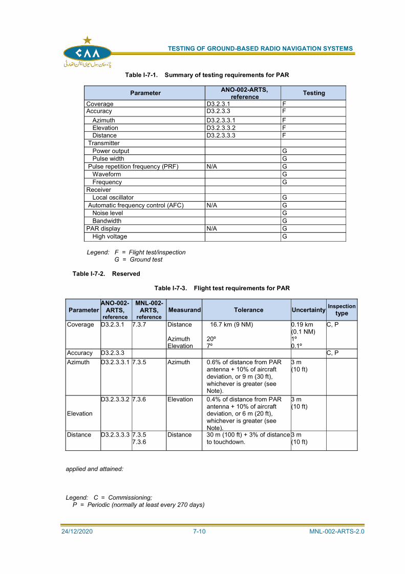
TESTING OF GROUND-BASED RADIO NAVIGATION SYSTEMS
24/12/2020 7-10 MNL-002-ARTS-2.0
Table I-7-1. Summary of testing requirements for PAR
Parameter ANO-002-ARTS,reference Testing
Coverage D3.2.3.1 FAccuracy D3.2.3.3 F
Azimuth D3.2.3.3.1 FElevation D3.2.3.3.2 FDistance D3.2.3.3.3 F
TransmitterPower output GPulse width G
Pulse repetition frequency (PRF) N/A GWaveform GFrequency G
ReceiverLocal oscillator G
Automatic frequency control (AFC) N/A GNoise level GBandwidth G
PAR display N/A GHigh voltage G
Legend: F = Flight test/inspection G = Ground test
Table I-7-2. Reserved
Table I-7-3. Flight test requirements for PAR
ParameterANO-002-
ARTS,reference
MNL-002-ARTS,
referenceMeasurand Tolerance Uncertainty Inspection
type
Coverage D3.2.3.1 7.3.7 Distance
AzimuthElevation
16.7 km (9 NM)
20º7º
0.19 km(0.1 NM)1º0.1º
C, P
Accuracy D3.2.3.3 C, PAzimuth D3.2.3.3.1 7.3.5 Azimuth 0.6% of distance from PAR
antenna + 10% of aircraftdeviation, or 9 m (30 ft),whichever is greater (seeNote).
3 m(10 ft)
Elevation
D3.2.3.3.2 7.3.6 Elevation 0.4% of distance from PARantenna + 10% of aircraftdeviation, or 6 m (20 ft),whichever is greater (seeNote).
3 m(10 ft)
Distance D3.2.3.3.3 7.3.57.3.6
Distance 30 m (100 ft) + 3% of distanceto touchdown.
3 m(10 ft)
applied and attained:
Legend: C = Commissioning;P = Periodic (normally at least every 270 days)
TESTING OF GROUND-BASED RADIO NAVIGATION SYSTEMS
24/12/2020 8-1 MNL-002-ARTS-2.0
Chapter 8
PERFORMANCE BASED NAVIGATION (PBN)
8.1 INTRODUCTION:
8.1.1 This chapter deals with the assessment and flight inspection of conventional navigationaids supporting instrument flight procedures which are not covered by the facility-specific chapters of this document. This concerns mainly the use of DME in supportingPBN. This chapter does not discuss flight validation because this is described in theQuality Assurance Manual for Flight Procedure Design (Doc 9906), Volume 5Validation of Instrument Flight Procedures. This does not preclude that the sameorganization which conducts flight inspection may also conduct flight validation. The useof global navigation satellite system (GNSS) to support PBN is addressed in Volume 2
Training Programme) of Doc 9906.
8.1.2 Use of VOR for PBN. The use of VOR in PBN is limited to VOR/DME supportingRNAV5. While multi-sensor avionics are normally capable of using VOR/DME for anRNAV solution, actual operational use is very limited.
8.1.3 Use of DME for PBN. Further guidance on the use of DME/DME to support RNAV iscontained in ANO-002-ARTS, Attachment C, 7.2.3. The main role of DME in PBN is tosupport RNAV1 and RNAV5 as a complementary terrestrial infrastructure alongsideGNSS.
8.2 GROUND ANALYSIS:
8.2.1 Infrastructure assessment for PBN. VOR and DME are identified in the Performance-based Navigation Manual (Doc 9613) and in Annex 10, Volume I, Attachment H, assensors which may support PBN operations and procedures. This may lead to VOR orDME signals being used in areas that are not normally flight inspected as part of thefacility specific testing, since the link between PBN and its supporting infrastructure isless direct. If an air navigation service provider (ANSP) wishes to offer PBN proceduresbased on conventional facilities, an infrastructure assessment should be conducted toensure that a minimum set of facilities is available which can be expected tosupport all equipped users.
Note: Further guidance on navigation infrastructure assessment to support RNAVprocedures is given in EUROCONTROL-GUID-0114 available athttp://www.eurocontrol.int and on the performance-based navigation (PBN) page of theICAO website at http://www.icao.int/pbn.
8.2.2 Linking infrastructure assessment and flight inspection. To support a particular PBNprocedure using conventional radio navigation aids, the ANSP should perform anassessment to determine if sufficient facilities are available to support a given area orprocedure with suitable geometry in accordance with the relevant PBN navigationspecification. This may require reliance on facilities being used in areas where they arenot normally flight inspected and where providing sufficient coverage (includingaccuracy) may be an issue. This assessment can be done with desktop software using aterrain and navigation facility database to determine coverage and resulting RNAVperformance. If the assessment concludes that sufficient VOR or DME facilities arebeing relied on only in areas which are either part of facility-specific inspection orwhere performance can be expected to be good based on engineering judgement,no RNAV-specific flight inspection may be required. If the assessment concludes thatthere are areas where performance should be verified, the assessment shouldspecify which facilities should be flight inspected in which areas. This normallyconcerns the use of facilities either at low altitudes (near line-of-sight taking into accountterrain) or at extended ranges, where multipath and signal blockage are more prevalent.
TESTING OF GROUND-BASED RADIO NAVIGATION SYSTEMS
24/12/2020 8-2 MNL-002-ARTS-2.0
Because this may concern multiple facilities, the assessment should be used to plan theflight inspection in as efficient a manner as possible. Flight inspection results should befed back into the infrastructure assessment. It may also be useful to note which DMEfacilities need to be operational to support a particular PBN procedure (when usingconventional navigation aids).
8.3 FLIGHT TESTING:
8.3.1 Flight inspection parameters and procedures. To evaluate if VOR or DME facilities areable to support PBN, both coverage (stable minimum field strength) and accuracyshould be verified using the methods specified in Chapters 2 and 3. Additionalparameters may be useful, such as reply efficiency in the case of DME. However, itmust be noted that some of the parameter limits and associated measurementprocedures have been defined only for radial or orbital flights. PBN specificationsassume that the facility requirements in Annex 10 will be met, regardless of theorientation of the aircraft. If flight inspection of multiple facilities is needed (such asseveral DME), the use of multi-channel DME test sets is encouraged to reduceoperational impact. When multi-channel DME measurement capabilities are used, itshould be ensured that they provide sufficient information to indicate adequate signalcoverage.
8.3.2 Periodicity of PBN-specific flight inspection. Once VOR and DME have been assessedand flight inspected where needed to show that they support a particular PBNprocedure, there is normally no further need for periodic inspection in mostenvironments. This assumes that safeguarding and/or appropriate facility-specificground and/or flight testing is established to ensure the signals supporting the PBNprocedure remain valid for use. If the navigation facilities supporting the procedure orthe procedure itself changes, the need for renewed flight inspection should be assessed.However, if flight validation is performed with a flight inspection aircraft, it is goodpractice to also verify the signals of the associated navigation aids.
______________________________

TESTING OF GROUND-BASED RADIO NAVIGATION SYSTEMS
24/12/2020 APPENDICES MNL-002-ARTS-2.0
A P P E N D I C E S

TESTING OF GROUND-BASED RADIO NAVIGATION SYSTEMS
24/12/2020 APPENDICES MNL-002-ARTS-2.0
INTENTIONALLY LEFT BLANK

TESTING OF GROUND-BASED RADIO NAVIGATION SYSTEMS
24/12/2020 APP A-1 MNL-002-ARTS-2.0
APPENDIX TO CHAPTER 4On the next few pages, a typical ILS routine report, including inspection of monitors, is presented togetherwith example graphs for each type of flight profile performed. Some flight inspection systems produceseveral graphs that may be collected during each profile to combine measurements and save flight hours.Some of the profiles may be repeated with different settings of ground equipment to achieve results fromboth Tx1 and Tx2 or for wide alarm and narrow alarm. An example set of profiles is given in Table A4-1-1below.
General remarks:
a) To reduce transcription errors, the report should be computer-generated by the flight inspectionsystem and include explanation of events, remarks and status of the equipment.
b) The report heading should contain a general section with basic report, crew and facility items.
c) An inspection identification key should be generated to keep track of all relevant data, graphs andrecords.
d) A system configuration key should identify actual hardware and software versions used by the flightinspection system.
e) From the inspection report it should be possible to trace back the utilized facility database settings,system calibration, antenna calibration diagrams, antenna lever arm corrections, cable loss and allrelevant data involved in or related to the calculations used.
f) Selected receivers, antennas, reference source and other selectable parameters must be traceablefor each profile.
g) Glide path (GP) aiming point offset calculations are terrain dependent and are normally calculatedand compensated for during commissioning.
h) Recordings and results should be configurable for ILS ground maintenance personnel in theirrequested format, e.g. with DDM instead of µA, if so required.
Specific remarks:
a) A full set of applicable calculated data are presented in the result section of the enclosed report.
b) The results should be automatically checked against the tolerances specified and applied by ICAOregulations (or otherwise towards stated regulations), and any out of tolerance situations should behighlighted (i.e. * or red colour).
c) The course and glide path structure calculation should be based on a 95 per cent probabilityaccording to ANO-002-ARTS, Figure C-2.
d) As found and as left results, with adjustments and repeated profiles, should be properly noted andexplained.
e) Width alarms are measured and shown on one transmitter for this sample; in practice this is asagreed in cooperation with ILS ground maintenance personnel.
f) If specific tests are requested by ILS ground maintenance personnel, the report should includeresults accordingly.
g) If any unforeseen events occur, this should be highlighted in the remarks section.
h) Current and any new restrictions applied should be properly referenced in the remarks section.
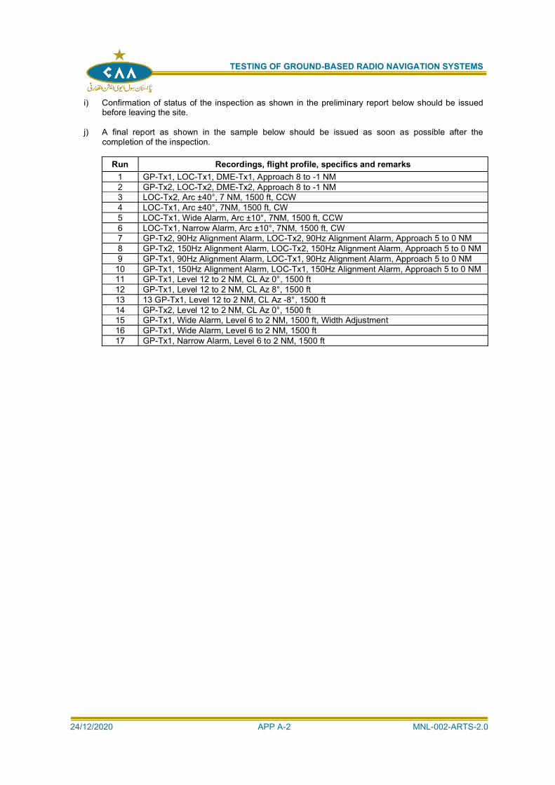
TESTING OF GROUND-BASED RADIO NAVIGATION SYSTEMS
24/12/2020 APP A-2 MNL-002-ARTS-2.0
i) Confirmation of status of the inspection as shown in the preliminary report below should be issuedbefore leaving the site.
j) A final report as shown in the sample below should be issued as soon as possible after thecompletion of the inspection.
Run Recordings, flight profile, specifics and remarks1 GP-Tx1, LOC-Tx1, DME-Tx1, Approach 8 to -1 NM2 GP-Tx2, LOC-Tx2, DME-Tx2, Approach 8 to -1 NM3 LOC-Tx2, Arc ±40°, 7 NM, 1500 ft, CCW4 LOC-Tx1, Arc ±40°, 7NM, 1500 ft, CW5 LOC-Tx1, Wide Alarm, Arc ±10°, 7NM, 1500 ft, CCW6 LOC-Tx1, Narrow Alarm, Arc ±10°, 7NM, 1500 ft, CW7 GP-Tx2, 90Hz Alignment Alarm, LOC-Tx2, 90Hz Alignment Alarm, Approach 5 to 0 NM8 GP-Tx2, 150Hz Alignment Alarm, LOC-Tx2, 150Hz Alignment Alarm, Approach 5 to 0 NM9 GP-Tx1, 90Hz Alignment Alarm, LOC-Tx1, 90Hz Alignment Alarm, Approach 5 to 0 NM
10 GP-Tx1, 150Hz Alignment Alarm, LOC-Tx1, 150Hz Alignment Alarm, Approach 5 to 0 NM11 GP-Tx1, Level 12 to 2 NM, CL Az 0°, 1500 ft12 GP-Tx1, Level 12 to 2 NM, CL Az 8°, 1500 ft13 13 GP-Tx1, Level 12 to 2 NM, CL Az -8°, 1500 ft14 GP-Tx2, Level 12 to 2 NM, CL Az 0°, 1500 ft15 GP-Tx1, Wide Alarm, Level 6 to 2 NM, 1500 ft, Width Adjustment16 GP-Tx1, Wide Alarm, Level 6 to 2 NM, 1500 ft17 GP-Tx1, Narrow Alarm, Level 6 to 2 NM, 1500 ft
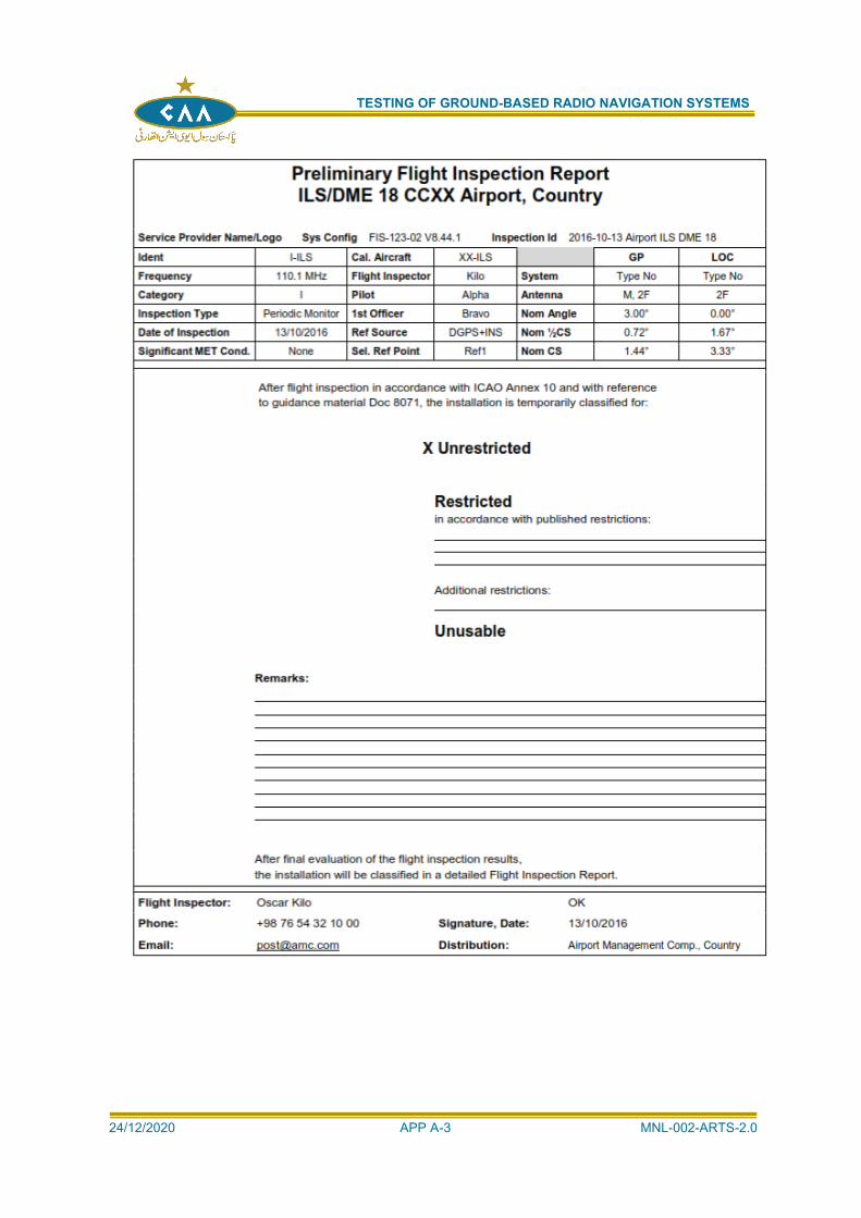
TESTING OF GROUND-BASED RADIO NAVIGATION SYSTEMS
24/12/2020 APP A-3 MNL-002-ARTS-2.0
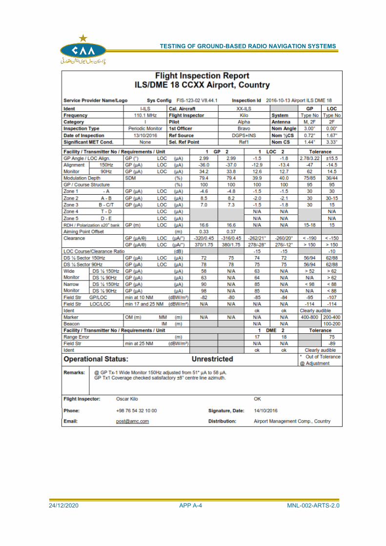
TESTING OF GROUND-BASED RADIO NAVIGATION SYSTEMS
24/12/2020 APP A-4 MNL-002-ARTS-2.0
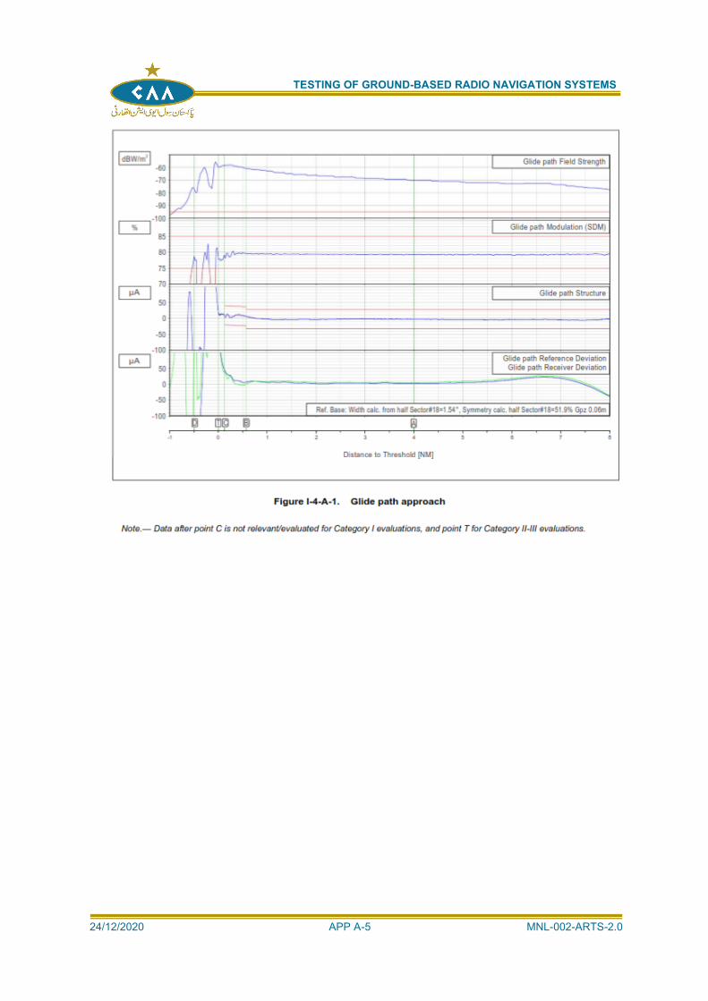
TESTING OF GROUND-BASED RADIO NAVIGATION SYSTEMS
24/12/2020 APP A-5 MNL-002-ARTS-2.0
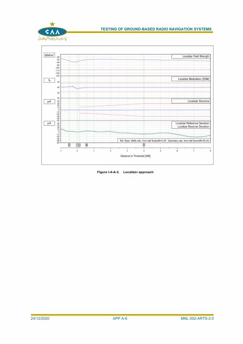
TESTING OF GROUND-BASED RADIO NAVIGATION SYSTEMS
24/12/2020 APP A-6 MNL-002-ARTS-2.0
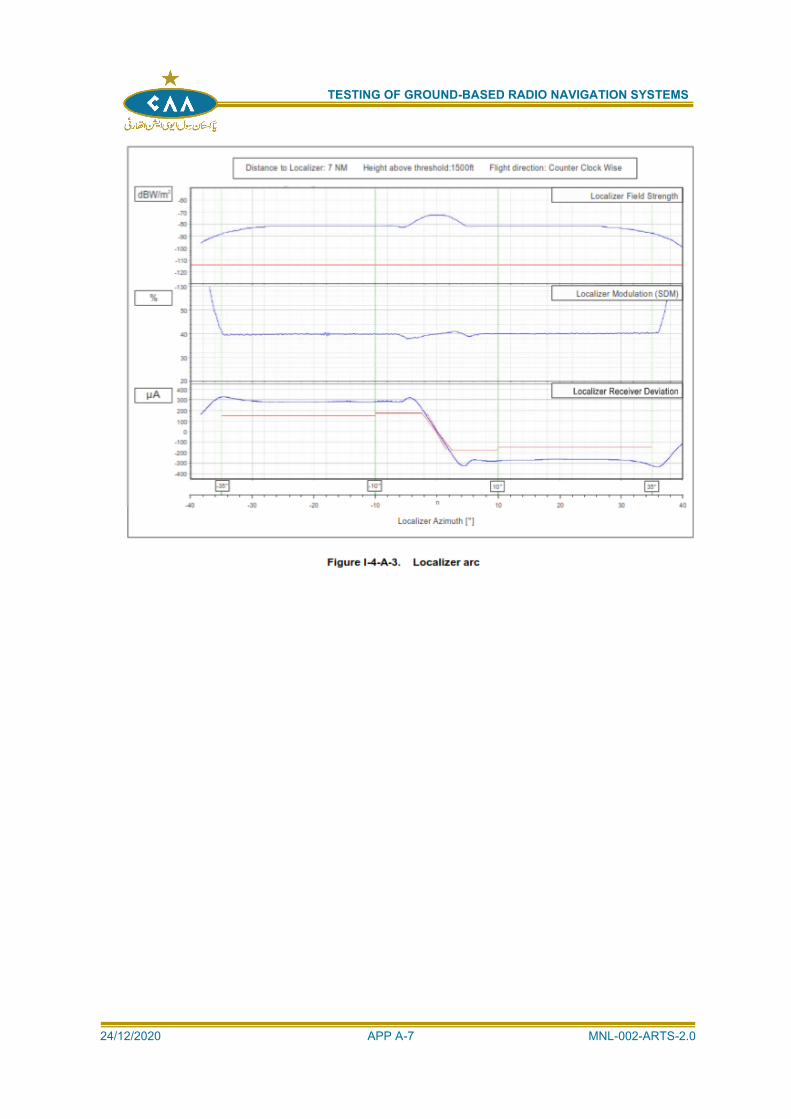
TESTING OF GROUND-BASED RADIO NAVIGATION SYSTEMS
24/12/2020 APP A-7 MNL-002-ARTS-2.0
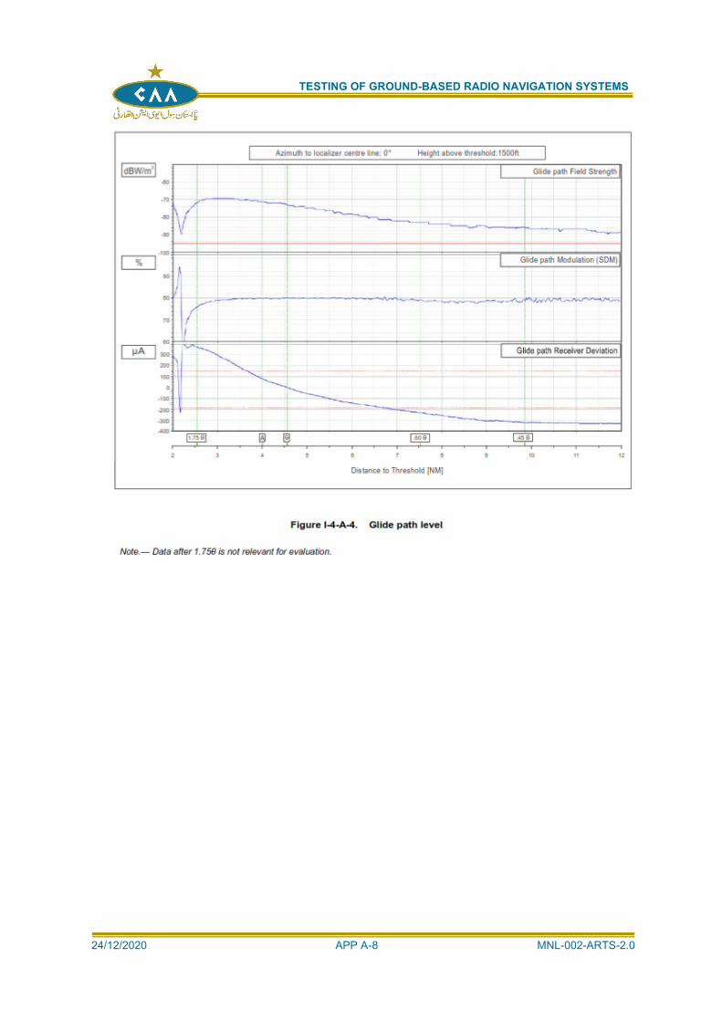
TESTING OF GROUND-BASED RADIO NAVIGATION SYSTEMS
24/12/2020 APP A-8 MNL-002-ARTS-2.0

TESTING OF GROUND-BASED RADIO NAVIGATION SYSTEMS
24/12/2020 APP A-9 MNL-002-ARTS-2.0
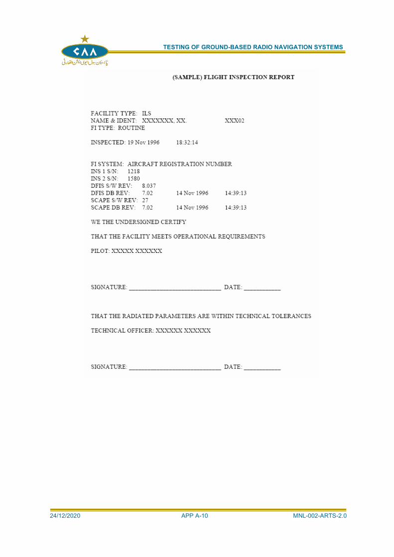
TESTING OF GROUND-BASED RADIO NAVIGATION SYSTEMS
24/12/2020 APP A-10 MNL-002-ARTS-2.0
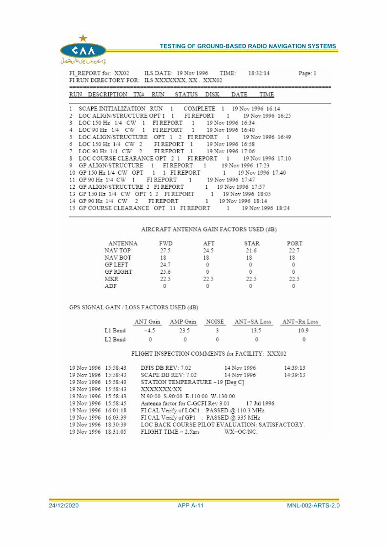
TESTING OF GROUND-BASED RADIO NAVIGATION SYSTEMS
24/12/2020 APP A-11 MNL-002-ARTS-2.0
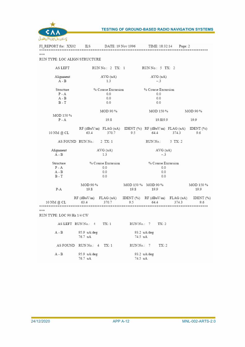
TESTING OF GROUND-BASED RADIO NAVIGATION SYSTEMS
24/12/2020 APP A-12 MNL-002-ARTS-2.0
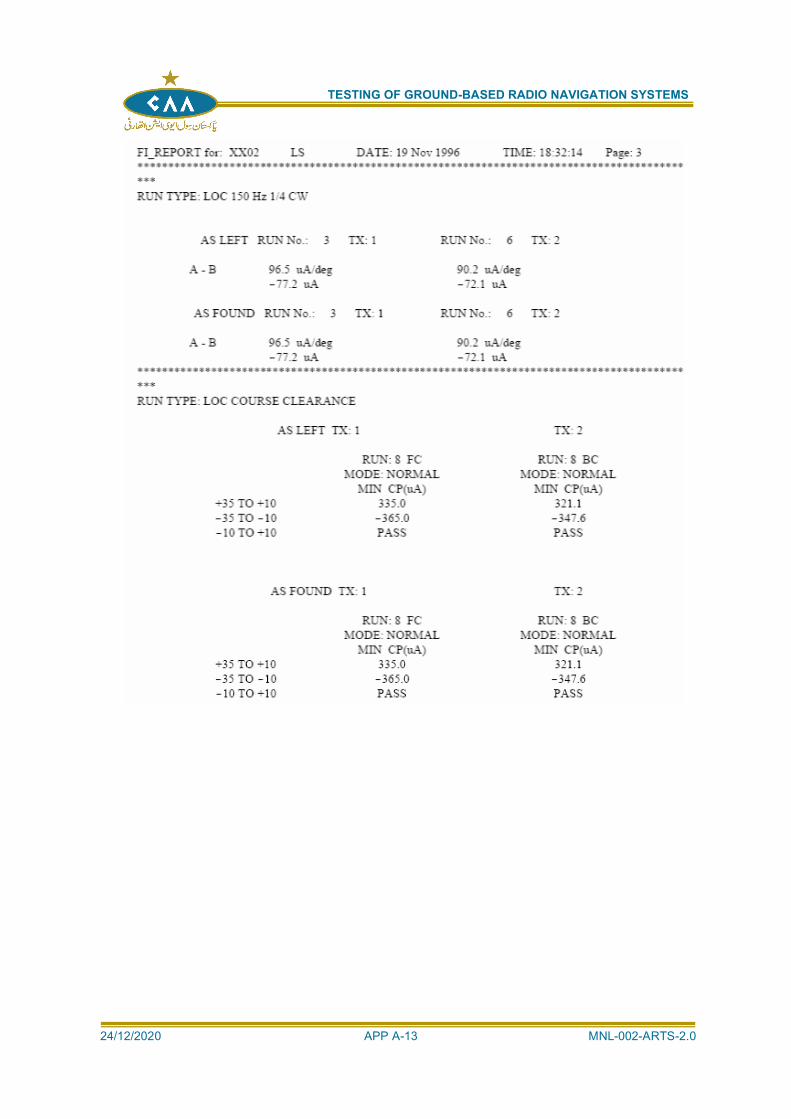
TESTING OF GROUND-BASED RADIO NAVIGATION SYSTEMS
24/12/2020 APP A-13 MNL-002-ARTS-2.0
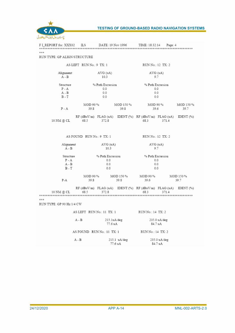
TESTING OF GROUND-BASED RADIO NAVIGATION SYSTEMS
24/12/2020 APP A-14 MNL-002-ARTS-2.0
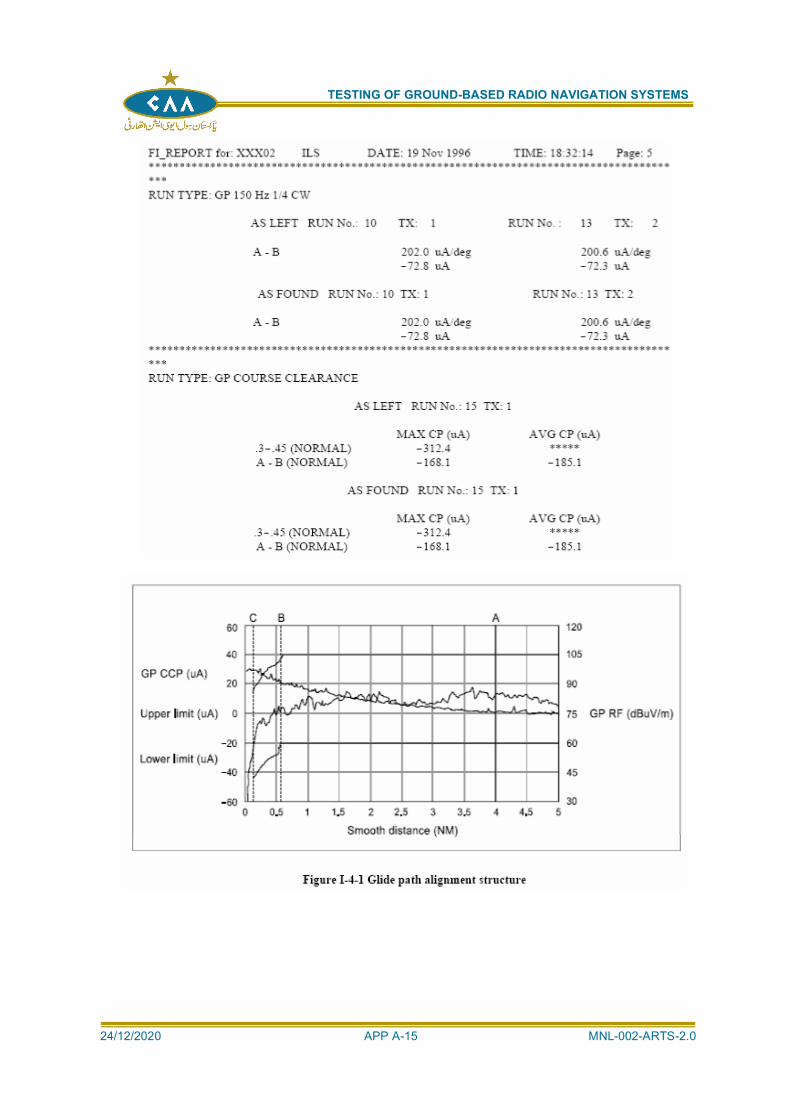
TESTING OF GROUND-BASED RADIO NAVIGATION SYSTEMS
24/12/2020 APP A-15 MNL-002-ARTS-2.0
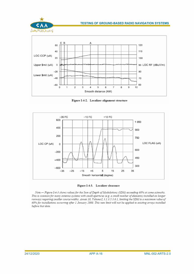
TESTING OF GROUND-BASED RADIO NAVIGATION SYSTEMS
24/12/2020 APP A-16 MNL-002-ARTS-2.0
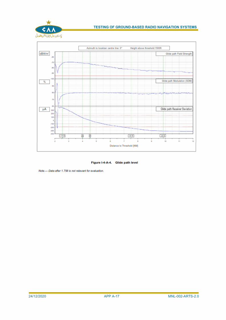
TESTING OF GROUND-BASED RADIO NAVIGATION SYSTEMS
24/12/2020 APP A-17 MNL-002-ARTS-2.0
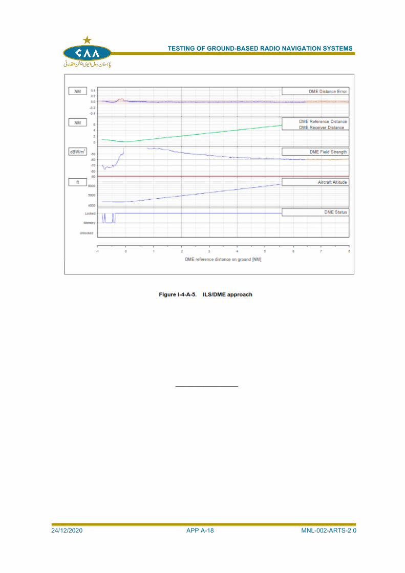
TESTING OF GROUND-BASED RADIO NAVIGATION SYSTEMS
24/12/2020 APP A-18 MNL-002-ARTS-2.0
__________________
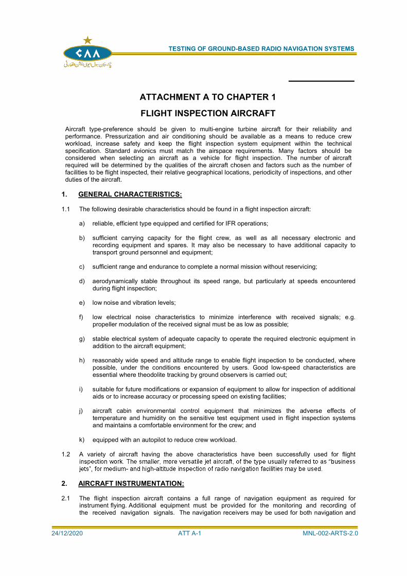
TESTING OF GROUND-BASED RADIO NAVIGATION SYSTEMS
24/12/2020 ATT A-1 MNL-002-ARTS-2.0
ATTACHMENT A TO CHAPTER 1
FLIGHT INSPECTION AIRCRAFTAircraft type-preference should be given to multi-engine turbine aircraft for their reliability andperformance. Pressurization and air conditioning should be available as a means to reduce crewworkload, increase safety and keep the flight inspection system equipment within the technicalspecification. Standard avionics must match the airspace requirements. Many factors should beconsidered when selecting an aircraft as a vehicle for flight inspection. The number of aircraftrequired will be determined by the qualities of the aircraft chosen and factors such as the number offacilities to be flight inspected, their relative geographical locations, periodicity of inspections, and otherduties of the aircraft.
1. GENERAL CHARACTERISTICS:
1.1 The following desirable characteristics should be found in a flight inspection aircraft:
a) reliable, efficient type equipped and certified for IFR operations;
b) sufficient carrying capacity for the flight crew, as well as all necessary electronic andrecording equipment and spares. It may also be necessary to have additional capacity totransport ground personnel and equipment;
c) sufficient range and endurance to complete a normal mission without reservicing;
d) aerodynamically stable throughout its speed range, but particularly at speeds encounteredduring flight inspection;
e) low noise and vibration levels;
f) low electrical noise characteristics to minimize interference with received signals; e.g.propeller modulation of the received signal must be as low as possible;
g) stable electrical system of adequate capacity to operate the required electronic equipment inaddition to the aircraft equipment;
h) reasonably wide speed and altitude range to enable flight inspection to be conducted, wherepossible, under the conditions encountered by users. Good low-speed characteristics areessential where theodolite tracking by ground observers is carried out;
i) suitable for future modifications or expansion of equipment to allow for inspection of additionalaids or to increase accuracy or processing speed on existing facilities;
j) aircraft cabin environmental control equipment that minimizes the adverse effects oftemperature and humidity on the sensitive test equipment used in flight inspection systemsand maintains a comfortable environment for the crew; and
k) equipped with an autopilot to reduce crew workload.
1.2 A variety of aircraft having the above characteristics have been successfully used for flight
2. AIRCRAFT INSTRUMENTATION:
2.1 The flight inspection aircraft contains a full range of navigation equipment as required forinstrument flying. Additional equipment must be provided for the monitoring and recording ofthe received navigation signals. The navigation receivers may be used for both navigation and
TESTING OF GROUND-BASED RADIO NAVIGATION SYSTEMS
24/12/2020 ATT A-2 MNL-002-ARTS-2.0
flight inspection. Special flight inspection receivers installed in addition to those used for navigationare preferable because of their special accuracy requirements.
2.2 When navigation receivers are shared between the pilot and observer, the control of the receiverduring flight inspection should be with the technician/engineer.
2.3 Inspection of PAR may require an on-board positioning system to record the azimuth, elevationand distance. The aircraft plays a passive role as a reflector of electromagnetic signals. Flightinspection procedures and Standards, particularly those relating to strength of signal return, areusually related to aircraft effective size as a reflector.
FLIGHT INSPECTION SYSTEM:
BUILD STATE AND MODIFICATION CONTROL:
2.4 The build state of all equipment, including test equipment, should be recorded and therecords should be updated whenever modifications or changes are made. Allmodifications should be accurately documented and cross- referenced to modificationstrikes or numbers on the equipment. After making any modification, tests andanalyses should ensure that the modification fulfils its intended purpose and that it has noundesired side effects.
CALIBRATION OF FLIGHT TEST EQUIPMENT:
2.5 All test equipment used for calibration, test or maintenance of an aeronautical navigationaid should be listed and subject to regular calibration checks. Each item of test equipmentshould have a documented calibration procedure and calibration records. Test equipment
indicated by objective evidence or operational conditions.
2.6 The conditions of use of individual items of test equipment should be fully considered
profile may be outside of the specified environmental conditions.
2.7 Regular calibration of the flight inspection receivers and position-reference system is to beperformed in order to ensure a back tracing of data to international or national standards.The calibration may be performed either on board the flight inspection aircraft or in alaboratory. In both cases, a test transmitter is connected to the radio frequency (RF) input ofthe receiver in order to input simulated signals. The receiver output is compared with thenominal signals; deviations are recorded either in a test protocol or by computer.Calibration data are applied either online by the computer or during offline dataevaluation.
CONTROL OF SPARES:
2.8 Equipment spares should be stored under suitable environmental conditions. Spares havinga limited lifetime, or requiring regular maintenance or calibration, should be suitably identifiedto that effect. Procedures should exist for the control, repair, and return-to-service ofequipment or modules. The procedures should show which modules may be repaired on-siteand which should be returned to the manufacturer or recognized repair facility.
SYSTEM BLOCK DIAGRAM AND DESCRIPTION
2.9 The flight inspection equipment as shown in Figure I-1-A-1 comprises:a) flight inspection receivers with associated antennas;
b) position-reference system;
c) equipment for data display and processing; and
d) equipment for data recording.
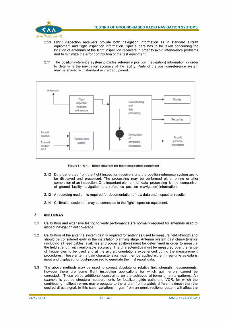
TESTING OF GROUND-BASED RADIO NAVIGATION SYSTEMS
24/12/2020 ATT A-3 MNL-002-ARTS-2.0
2.10 Flight inspection receivers provide both navigation information as in standard aircraftequipment and flight inspection information. Special care has to be taken concerning thelocation of antennas of the flight inspection receivers in order to avoid interference problemsand to minimize the error contribution of the test equipment.
2.11 The position-reference system provides reference position (navigation) information in orderto determine the navigation accuracy of the facility. Parts of the position-reference systemmay be shared with standard aircraft equipment.
2.12 Data generated from the flight inspection receivers and the position-reference system are tobe displayed and processed. The processing may be performed either online or aftercompletion of an inspection. One important element of data processing is the comparisonof ground facility navigation and reference position (navigation) information.
2.13 A recording medium is required for documentation of raw data and inspection results.
2.14 Calibration equipment may be connected to the flight inspection equipment.
3. ANTENNAS
3.1 Calibration and extensive testing to verify performance are normally required for antennas used toinspect navigation aid coverage.
3.2 Calibration of the antenna system gain is required for antennas used to measure field strength andshould be considered early in the installation planning stage. Antenna system gain characteristics(including all feed cables, switches and power splitters) must be determined in order to measurethe field strength with reasonable accuracy. The characteristics must be measured over the rangeof frequencies to be used and at the aircraft orientations experienced during the measurementprocedures. These antenna gain characteristics must then be applied either in real-time as data isinput and displayed, or post-processed to generate the final report data.
3.3 The above methods may be used to correct absolute or relative field strength measurements,however, there are some flight inspection applications for which gain errors cannot becorrected. These place additional constraints on the achieved airborne antenna patterns. Anexample is course structure measurements for localizer, glide path, and VOR, for which thecontributing multipath errors may propagate to the aircraft from a widely different azimuth than thedesired direct signal. In this case, variations in gain from an omnidirectional pattern will affect the
TESTING OF GROUND-BASED RADIO NAVIGATION SYSTEMS
24/12/2020 ATT A-4 MNL-002-ARTS-2.0
measured amplitude of the course structure, with or without aircraft attitude variations, and flightmeasurements, by differing aircraft types, will vary. Flight inspection organizations should makeevery reasonable effort to achieve antenna patterns that represent the antennas used by the fleet
ANTENNA MEASUREMENT TECHNIQUES:
3.4 Many techniques, including mathematical modelling, reduced-scale modelling, full-scaleground testing and flight testing, are available for optimizing the location of antennas andcharacterizing their gain in a given location on an aircraft. The complexity and cost aregenerally proportional to the number of azimuth and elevation angles to be measured as wellas the accuracy required of the measurements. The overall cost is reduced if a combinationof modelling and ground testing is used to establish expected performance; flight testingwould then be used as the final confirmation stage.
3.5 Flight test techniques capable of full azimuth or lower hemisphere characterization with highaccuracy are now available through many flight test ranges, these should be the preferredmethods used to provide confirmation of antenna patterns. Procedures that provideongoing confirmation of antenna performance are still required and some form of ramp-based check should be established.
3.6 Consideration should also be given to characterizing the localizer antenna pattern over the
compatibility (EMC) problems from FM broadcast stations. A separate broadband antennamay be fitted if the aircraft is to be used for general interference investigation
INSTALLATION CONSIDERATIONS:
3.7 Antenna installation can affect the flight inspection measurements and the operational useof the aircraft in many ways. The following are a few examples:
a) Propeller modulation effects can interfere with the received ILS localizer signal over arange of engine power settings. This can severely limit the use of the aircraft forflight inspection. Improving the antenna location is the best solution to this problem,followed by the modification of the propeller frequency. The formula below shows thepropeller modulation frequency.
Propeller Modulation Frequency (Hz) = Shaft Rotation Speed (RPM) x Number of PropellerBlades/60
Examples:
3-blade propeller at 1800 RPM: 1800 x 3 / 60 = 90 Hz > BAD for ILS4-blade propeller at 1800 RPM: 1800 x 4 / 60 = 120 Hz > OK for ILSb) Physical movement of other antennas, such as the weather radar, may affect the signal
received from a glide path antenna located nearby. The weather radar may have to beparked in a known orientation to obtain stable glide path signals.
c) Cross-coupling between aircraft transmitter antennas and receiving antennas caneasily occur. Care must be taken to ensure adequate separation between potentialinterfering sources, such as VHF communications antennas and VOR/ILS localizerantennas.
d) Aircraft structures must be taken into account when selecting antenna locations. Themounting of antennas near discontinuities in material types should be avoided if a goodground plane is required. Metallic support rods stowed inside a composite material nosecone can act as re-radiators affecting the performance of a nearby antenna.
e) When one antenna is used to feed two or more receivers there is potential forreceiver interaction resulting in an uncalibrated change to the antenna system gain. It isrecommended that separate antennas be provided for the flight inspection receivers.Testing is recommended when a shared antenna must be used to ensure that tuning the
TESTING OF GROUND-BASED RADIO NAVIGATION SYSTEMS
24/12/2020 ATT A-5 MNL-002-ARTS-2.0
second receiver over the band does not affect the signal level reaching the receiver usedfor coverage measurements.
f) Changes in aircraft attitude will affect the relative positions of the antenna and trackingreference point if the aircraft measuring antennas are not located at the same point asthe reference for the tracking system as seen from the ground. Certain flight inspectionsystems correct this by using software and inputs from the aircraft navigation sensors.
g) The position of the phase centre for some types of antennas will vary according tothe direction of arrival of the signals. Measurements have shown that the effectivephase centre may move outside the physical area of the antenna. This change inposition of the phase centre should be included in any correction algorithms which maybe used.
4. FLIGHT INSPECTION RECEIVERS AND RADIO COMMUNICATION EQUIPMENT:
4.1 Flight inspection receivers are to be of the highest quality in order to obtain the accuracyrequired for flight inspection purposes and should provide additional measurement outputsspecific to flight inspection. A dual set of receivers is preferable to reduce statistical errors.
4.2 Flight inspection receivers include an AGC measurement. The AGC information allows thedetermination of the field strength if the receiver and antenna characteristic is taken intoaccount. Further components have to be added like a temperature control for the receiveror a further dedicated receiver if the stability of the flight inspection receiver AGC output isnot sufficient.
4.3 Flight inspection receivers used for the calibration of pulsed navigation facilities, such asDME and radars, provide the video signal of these facilities.
4.4 A radio is included in the flight inspection equipment in order to allow independentcommunication between the flight inspector and the ground crew, without affecting the pilot.
5. DATA PROCESSING, DISPLAY AND RECORDING:
5.1 Modern flight inspection equipment includes a computer, which is used to read thedata from the position-reference system and from the flight inspection receivers. Thecomputer processes data in order to compare the facility navigation information and theposition reference information. The computer has the capability of determining facilityparameters, e.g. ILS localizer course width, alignment, etc.
5.2 The comparison of facility navigation information and position-reference pointinformation may be performed with an analog solution, if the flight inspection system doesnot include a computer for calculating the results. The facility parameters have to becalculated manually in this case.
5.3 All relevant information like facility navigation information, reference information, facility errorand additional receiver information, such as field strength, is displayed on board the flightinspection aircraft for the operator. Data may be displayed on analog or digital instrumentsas well as on computer screens.
5.4 Chart recorders or printers can be used for the documentation of flight inspection results. Alldata are annotated properly either by the operator or automatically by the data-processingsystem.
5.5 All raw data and computed data are recorded in electronic format on tapes or disks, ifpossible. This enables a later post-processing, if a specific investigation is required.
6. REGULATORY ASPECTS:
6.1 Integration of the systems in the aircraft must not affect the Airworthiness Certificate of theaircraft. Every modification has to be recorded in the technical documentation of the aircraft,along with the approvals of the manufacturer and of the certification authority concerned
TESTING OF GROUND-BASED RADIO NAVIGATION SYSTEMS
24/12/2020 ATT A-6 MNL-002-ARTS-2.0
6.2 Particular operating instructions should be registered in flight and exploitation manuals. Ifthis integration entails any performance limitations or operational restrictions for the aircraft,they should appear clearly in the corresponding documents.
6.3 The integration of a flight inspection system results from the best compromise takinginto account airworthiness constraints
__________________________
TESTING OF GROUND-BASED RADIO NAVIGATION SYSTEMS
24/12/2020 ATT B-1 MNL-002-ARTS-2.0
ATTACHMENT B TO CHAPTER 1
DOCUMENTATION AND DATA RECORDING
1. FLIGHT INSPECTION REPORTS
1.1 The flight inspection report serves as the basic means of documentation and disseminationof the results of each flight inspection. The flight inspector in charge is responsible forinitiating the report and ensuring that it clearly records the results of each parametermeasured, along with an assessment of the conformance of the facility performance to therequired standards. This assessment will normally involve an analysis of the data recordingsand a review of the computer-aided analysis carried out on the data gathered during the
entered into routine documentation of the adjustments made to the facilities.
1.2 Flight inspection reports typically include the following information:
a) station name and facility designation;
b) category of operation;
c) date(s) of inspection;
d) serial number of report/unique identifier;
e) type of inspection, e.g. routine or annual;
f) aircraft registration;
g) manufacturer and type of system being inspected;
h) wind conditions, to allow cross-wind to be established;
i) names and functions of all personnel involved in the inspection;
j) method of making each measurement (where alternatives are available); these may bereferenced to the operating instructions;
k) details of associated attachments, e.g. recordings;
l) details of extra flights made necessary by system adjustments;
m) an assessment by the flight crew of the navigation facility performance;
n) comments by the flight inspector/equipment operator;
o) details of any immediately notifiable deficiencies
p) results and tolerances;
q) statement of conformance/nonconformance; and
r) signatures of appropriate personnel.
1.3 A confirmation of the status of the inspection should be provided immediately after theinspection.
TESTING OF GROUND-BASED RADIO NAVIGATION SYSTEMS
24/12/2020 ATT B-2 MNL-002-ARTS-2.0
2. FLIGHT INSPECTION DATA RECORDINGS:The flight inspection data recordings serve as a record of the raw signal information used toassess ground facility performance. The recording medium may be a strip chart or electronic filesof sampled data. Data recordings are normally archived and maintained on file with the flightinspection reports. This data should be made available to engineering and maintenance personnelfor solving site problems and for assessing trends in facility or equipment performance.
3. FLIGHT INSPECTION SYSTEM CALIBRATION:Many of the components in a typical flight inspection system, as well as secondary or transferstandards, such as signal generators, must be calibrated on a periodic basis to ensuremeasurements are made with the required accuracy. Records of the calibration results (includingthe specific test equipment used) must be retained to ensure the calibration is traceable back tonational measurement standards. The flight inspection organization shall ensure policies andprocedures are in place to track the calibration status of equipment and recall equipmentfor calibration at the established intervals.
4. GROUND FACILITY DATA:Facility data sheets or computer files serve as a useful tool in providing the inspector and theflight inspection system with accurate information regarding facility survey data, facility andequipment types, frequencies, etc. Such information is normally prepared at the time ofcommissioning and revised as necessary to maintain current data. Its purpose is best served if thedata are made part of a file to be carried in the aircraft or loaded into the flight inspection system.
5. RETENTION OF FLIGHT INSPECTION REPORTS AND DATA:Each flight inspection organization is responsible for ensuring that sufficient historical data areretained to establish the trends in facility performance over a reasonable interval of time. As aminimum, all commissioning inspection reports and data recordings should be retained in thefacility file along with reports and data recordings from the last five periodic inspections. All specialflight inspections carried out during this time period should be retained on file.
6. GROUND TEST REPORTS:It is recommended that the initial performance of a navigation aid facility be established through aformal proof of performance (POP) test and report. The facility is normally released for operationaluse once a satisfactory commissioning flight inspection is complete. It is normal practice thatmaintenance staff be certified to maintain the navigation aid in accordance with prescribed policiesand procedures. These policies and procedures will normally specify what ground documentationand reports are required and the period for which they must be retained. It is recommended thatthe POP test report and reports on the implementation of modifications to the facility be retainedthroughout the life of the facility. Reports on routine maintenance actions should be maintained fora minimum of one year.
7. GROUND CALIBRATION REPORTS:Many of the components in a typical navigation aid system, as well as secondary or transferstandards, such as signal generators, must be calibrated on a periodic basis to ensure a facility isoperating as intended. Reports of the calibration results (including the specific test equipmentused) must be retained to ensure that measurements are traceable back to national calibrationstandards. The responsible maintenance organization shall ensure policies and procedures are inplace to track the calibration status of equipment and recall equipment for calibration at theestablished intervals.
_______________________
TESTING OF GROUND-BASED RADIO NAVIGATION SYSTEMS
24/12/2020 ATT C-1 MNL-002-ARTS-2.0
ATTACHMENT C TO CHAPTER 1 INTERFERENCE ISSUES
1. INTERFERENCE EFFECTS:Interference to a navigation aid can manifest itself in many ways. A VOR receiver may appear tooperate normally but indicate a solid bearing to an adjacent co-channel facility. A localizerdeviation signal may become erratic while FM broadcast is heard on the receiver audio output.The glide path signal may be lost momentarily as an aircraft passes over an industrial facility. AGNSS receiver used for position-reference may lose track of satellites due to interference.Interference may be caused by not providing adequate separation between facilities on the samefrequency. Ground- based non-aeronautical services such as FM broadcast stations may be thecause. Interference may originate on board the aircraft due to a poor avionics installation or fromcarry-on equipment. There are many possible sources and the probability of interferenceoccurring is increasing as the frequency spectrum becomes more congested.
2. INTERFERENCE SOURCES:Note: The following sources account for most of the problems affecting radio navigationor radio communications receivers.
GROUND-BASED AERONAUTICAL SOURCES:
2.1 Aeronautical facilities are engineered, installed and maintained to avoid causinginterference to users of other aeronautical facilities. The service volumes of aeronauticalfacilities are protected from co-channel and adjacent channel interference by usingfrequency coordination procedures based on minimum and maximum field strengths andprotection criteria promulgated primarily in Annex 10. In-band interference is usuallycaused by malfunctioning transmitters, frequency coordination problems and receiveroperation outside the protected service volume of the aeronautical facility. The use of signalgenerators on operational aeronautical frequencies during avionics testing can causeinterference problems.
GROUND-BASED NON-AERONAUTICAL SOURCES:
2.2 These sources include broadcast transmitters and emitters such as industrial, scientific andmedical (ISM) equipment and power lines. RF emitters are normally licensed and mustcomply with International Telecommunication Union (ITU) Radio Regulations and domesticregulations. Malfunctioning transmitters and unintentional emitters are the cause of manyinterference problems.
FM BROADCAST TRANSMITTERS:
communications receivers. Two general types of interference can occur. The first iscaused by FM broadcast emissions that fall inside the aeronautical band, such asintermodulation products generated when multiple FM transmitters feed one antenna orout-of-band emissions from stations operating at the upper edge of the FM band. Thesecond type is generated within the navigation receiver in response to FM broadcastemissions that fall outside the aeronautical band. These are usually intermodulation orreceiver desensitization effects caused by high-level signals outside the aeronautical band.
2.4 AN-002-ARTS D3.1.4 and D 3.3.8, and associated guidance material in Attachment C,contain FM immunity performance criteria for ILS and VOR receivers and additional relatedITU references. The ICAO Handbook for Evaluation of Electromagnetic CompatibilityBetween ILS and FM Broadcasting Stations Using Flight Test* provides guidance onconducting flight tests of this kind of interference.
TESTING OF GROUND-BASED RADIO NAVIGATION SYSTEMS
24/12/2020 ATT C-2 MNL-002-ARTS-2.0
TV BROADCAST TRANSMITTERS:
2.5 Harmonics, intermodulation products and spurious emissions of TV video and audiocarriers may cause interference to DME, VHF communications, VOR and ILSreceivers, and GNSS.
LAND MOBILE TRANSMITTERS:
2.6 In-band interference can be caused by spurious emissions from a single transmitteror by radiated intermodulation products created at a co-sited facility. VHFcommunications frequencies are often affected because a fixed/mobile service bandlies immediately above 137 MHz. The mobile satellite service operating in the bandadjacent to the GNSS band or the fixed service operating in the GNSS band cancause interference to GNSS receivers.
CABLE TELEVISION DISTRIBUTION SYSTEMS:
2.7 These CATV systems distribute TV broadcasting signals on ILS and VHFcommunications frequencies. Most CATV systems use coaxial cables, which canleak RF signals and cause in-band interference.
INDUSTRIAL, SCIENTIFIC AND MEDICAL (ISM) SYSTEMS:
2.8 Specific radio frequency bands (e.g. centred at 13.56, 27.12 and 40.98 MHz)are allocated for the operation of ISM equipment. In-band interference to VHFcommunications, VOR and ILS localizer receivers may be caused by the radiationof harmonics of the ISM frequencies from malfunctioning or inadequatelyshielded ISM equipment. The interfering signal sweeps repetitively through a portionof the VHF aeronautical band affecting several aeronautical frequencies. The mostcommon ISM interference sources are industrial equipment such as plastic welders.
POWER LINE DISTRIBUTION SYSTEMS:
2.9 Power line carrier (PLC) systems inject signals into power lines for monitoring andcontrol purposes. ADF receivers can experience in-band interference because somePLC systems operate within the NDB band and PLC signals can radiate from powerlines.
2.10 Corona noise and gap discharges from malfunctioning electrical equipment such ashigh-voltage bus-bars, switchgear, and insulators, can generate broadbandimpulsive-type noise, which can interfere with ILS localizer, VOR and VHFcommunications receivers in over-flying, low-altitude aircraft.
OTHER GROUND-BASED NON-AERONAUTICAL SOURCES:
2.11 Low/medium/high frequency (LF/MF/HF) transmitters can cause co-channel andadjacent channel interference to ADF and HF communications receivers. High-powermilitary radar may generate harmonic and spurious emission levels high enough tocause in-band and out-of-band interference to on-board pulse-type systems such asGNSS receivers. Radiated emissions from most information technology equipment(ITE) are regulated domestically. Malfunctioning ITE can cause in-band interference.Radiation of ITE clock frequency signals and their harmonics can interfere with VHFare regulated domestically. Malfunctioning ITE can cause in-band interference.Radiation of ITE clock frequency signals and their harmonics can interfere with VHFcommunications, ILS localizer, VOR and other receivers.
AIRBORNE EQUIPMENT SOURCES:
2.12 On-board aeronautical transmitters may cause in-band interference to aircraftreceivers through harmonics of the intentional emissions or harmonics of localoscillator frequencies being conducted between units. Potential problems associated
* Available from the ICAO Air Navigation Bureau upon request (English only).
TESTING OF GROUND-BASED RADIO NAVIGATION SYSTEMS
24/12/2020 ATT C-3 MNL-002-ARTS-2.0
with portable electronic device installations on-board aircraft should normally beidentified and resolved during airworthiness testing.
AIRBORNE EQUIPMENT SOURCES:
2.13 On-board aeronautical transmitters may cause in-band interference to aircraft receiversthrough harmonics of the intentional emissions or harmonics of local oscillator frequenciesbeing conducted between units. Potential problems associated with portable electronicdevice installations on-board aircraft should normally be identified and resolved duringairworthiness testing.
3. GENERAL METHODS FOR DETECTING AND RESOLVING INTERFERENCEPROBLEMS
3.1 There are many possible approaches to detecting and resolving interference problems.They all should be considered as tools to be applied when required.
EMC EVENT-REPORTING SYSTEM:
3.2 An interference problem is often first observed by users of the navigation aid. Therefore,pilot and ATC reports are the first step in identifying the nature and approximate locationsof where it occurs. The reporting system should be used to establish a point-of-contactbetween the users who observed the interference and the agency charged with resolvingsuch occurrences.
GROUND MONITORING:
3.3 The increasing pollution of the electromagnetic environment at or near airports may be amajor concern to some areas. It can be a particular problem near major airports with alarge number of aeronautical systems. The local electromagnetic environment tends to bemore congested by the many ground-based non-aeronautical interference sources.Ground-based monitoring systems to detect interference events are being developed.
3.4 The protection of the integrity of the signal-in-space against degradation, which can arisefrom extraneous radio interference falling within the ILS frequency band, must beconsidered. This is particularly important where the ILS is used for Category II and IIIapproach and landing operations. It is necessary, therefore, to periodically confirm that theradio environment at each Category II/III runway does not constitute a hazard
TECHNICAL CONFIRMATION OF THE INTERFERENCE:
3.5 Ground and/or airborne test equipment deployment to obtain technical measurements willdepend on how and where the interference manifests itself.
3.6 Most flight inspection aircraft can readily record the effects of the interference onreceiver AGC, cross-pointer, flag and audio signals, as well as determine the aircraftposition and altitude when interference is observed. Confirmation of the interferencecharacteristics and location by the flight inspection service is a second step toward solvingthe problem. More detailed information can be obtained about the relative signal levels andthe frequencies being received at the aircraft antenna if the flight inspection aircraft isequipped with a spectrum analyser or field strength metre. Recording of the audio channelof the affected receiver, spectrum analyser or field strength meter is useful in identifying theinterference source through its unique demodulated audio characteristics. A simple testsuch as inserting a suitable RF filter ahead of the receiver can often assist inidentifying whether an interference source is in-band or out-of-band.
3.7 Confirmation of a suspected interference source can be achieved by switching thesuspected source on and off several times and noting the resulting effects on the affectedreceiver.
3.8 It should be noted that there will be cases where the ground test equipment or the flightinspection aircraft may not be able to detect/confirm reported interference problems
TESTING OF GROUND-BASED RADIO NAVIGATION SYSTEMS
24/12/2020 ATT C-4 MNL-002-ARTS-2.0
because:
a) the receiver systems used in the air or on the ground (i.e. receiver, antenna, andcable system) may have significantly different performance characteristics from thosereceiver systems reported to have experienced interference;
b) interference is intermittent and may not be occurring during the investigative flight test;or
c) it may be difficult to find a ground observation point which corresponds to theinterference conditions seen in the air.
SPECIALIZED ELECTROMAGNETIC INTERFERENCE (EMI) TROUBLESHOOTINGMETHODS:
3.9 Specialized equipment and computer simulation will likely be required if a source ofinterference cannot be readily identified. Considerable time and effort may be invested onhardware and software techniques to resolve EMI problems. These techniques include:
a) databases of potential interference sources;
b) EMC analysis software;
c) interference simulators;
d) special ground or airborne data acquisition systems;
e) interference direction-finding systems; and
f) antenna calibration techniques.
INTERFERENCE INVESTIGATION:
3.10 It may be helpful, in resolving the more difficult interference problems, to form aninvestigative team consisting of personnel representing (as required) flight inspection
and aeronautical facility engineering/maintenance. This team could seek input from theaffected users and the owner/operator of the potential interference source, developand implement test plans, analyse results and make recommendations for resolvinginterference problems
END OF MANUAL________________________________