testing/rating windstorm resistant components - swinging
TRANSCRIPT

Testing and Rating of — Severe Windstorm Resistant Components for Swinging Door Assemblies for Protection of Building Envelopes (Not applicable for FEMA 320/361 or ICC-500 Shelters)
ANSI A250.13-2014 (R2018)Revision of ANSI A250.13-2008
AN
SI A
250.
13-2
014
SPONSORS
Steel Door Institute and Builders Hardware Manufacturers’ Association
Approved February 25, 2014

This page left intentionally blank.

®ANSIA250.13-2014
Revision ANSI A250.13-2008
American National Standard Testing and Rating of —
Severe Windstorm Resistant Components for Swinging Door Assemblies for Protection of Building Envelopes
(Not applicable for FEMA 320/361 or ICC-500 Shelters)
Approved February 25, 2014
American National Standards Institute, Inc.
Secretariat
Steel Door Institute

AmericanNationalStandard
Approval of an American National Standard requires verification by ANSl that the requirements for due process, consensus, and other criteria for approval have been met by the standards developer.
Consensus is established when, in the judgement of the ANSl Board of Standards Review, substantial agreement has been reached by directly and materially affected interests. Substantial agreement means much more than a simple majority, but not necessarily unanimity. Consensus requires that all views and objections be considered, and that a concerted effort be made toward their resolution.
The use of American National Standards is completely voluntary; their existence does not in any respect preclude anyone, whether they have ap-proved the standards or not, from manufacturing, marketing, purchasing, or using products, processes, or procedures not conforming to the standards.
The American National Standards Institute does not develop standards and will in no circumstances give any interpretation of any American National Standard. Moreover, no person shall have the right or authority to issue an interpretation of an American National Standard in the name of the American National Standards Institute. Requests for interpretations should be addressed to the secretariat or sponsor whose name appears on the title page of this standard.
CAUTION NOTICE: This American National Standard may be revised or withdrawn at any time. The procedures of the American National Standards Institute require that action be taken periodically to reaffirm, revise, or withdraw this standard. Purchasers of American National Standards may receive current information on all standards by calling or writing the Ameri-can National Standards Institute.
No part of this publication may be reproduced in any form, in an electronic retrieval system or otherwise, without prior written permission of the publisher.
Printed in the United States of America
ANSI A250.13-2014
Published by
Steel Door Institute30200 Detroit Road, Cleveland, Ohio 44145-1967
Copyright © 2018 by Steel Door InstituteAll rights reserved.
i
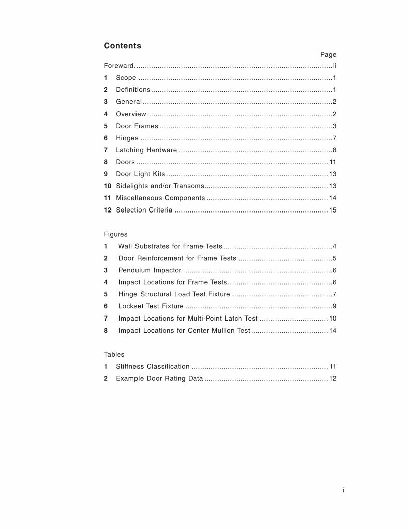
PageContents
Foreward ............................................................................................. ii
1 Scope ...........................................................................................1
2 Definitions .....................................................................................1
3 General .........................................................................................2
4 Overview .......................................................................................2
5 Door Frames .................................................................................3
6 Hinges ..........................................................................................7
7 Latching Hardware ........................................................................8
8 Doors .......................................................................................... 11
9 Door Light Kits ............................................................................ 13
10 Sidelights and/or Transoms .......................................................... 13
11 Miscellaneous Components ......................................................... 14
12 Selection Criteria ........................................................................ 15
Figures
1 Wall Substrates for Frame Tests ...................................................4
2 Door Reinforcement for Frame Tests ............................................5
3 Pendulum Impactor ......................................................................6
4 Impact Locations for Frame Tests .................................................6
5 Hinge Structural Load Test Fixture ...............................................7
6 Lockset Test Fixture .....................................................................9
7 Impact Locations for Multi-Point Latch Test ................................ 10
8 Impact Locations for Center Mullion Test .................................... 14
Tables
1 Stiffness Classification ................................................................ 11
2 Example Door Rating Data .......................................................... 12
ii
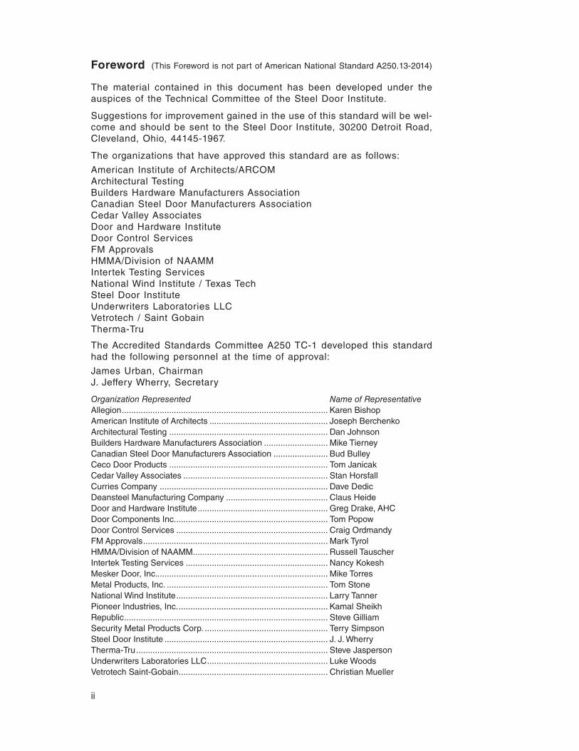
Foreword (This Foreword is not part of American National Standard A250.13-2014)
The material contained in this document has been developed under the auspices of the Technical Committee of the Steel Door Institute.
Suggestions for improvement gained in the use of this standard will be wel-come and should be sent to the Steel Door Institute, 30200 Detroit Road, Cleveland, Ohio, 44145-1967.
The organizations that have approved this standard are as follows:
American Institute of Architects/ARCOM Architectural TestingBuilders Hardware Manufacturers AssociationCanadian Steel Door Manufacturers AssociationCedar Valley AssociatesDoor and Hardware InstituteDoor Control ServicesFM ApprovalsHMMA/Division of NAAMMIntertek Testing ServicesNational Wind Institute / Texas TechSteel Door InstituteUnderwriters Laboratories LLCVetrotech / Saint GobainTherma-Tru
The Accredited Standards Committee A250 TC-1 developed this standard had the following personnel at the time of approval:
James Urban, ChairmanJ. Jeffery Wherry, Secretary
Organization Represented Name of RepresentativeAllegion ....................................................................................... Karen BishopAmerican Institute of Architects .................................................. Joseph Berchenko Architectural Testing ................................................................... Dan JohnsonBuilders Hardware Manufacturers Association ........................... Mike TierneyCanadian Steel Door Manufacturers Association ....................... Bud BulleyCeco Door Products ................................................................... Tom JanicakCedar Valley Associates ............................................................. Stan HorsfallCurries Company ....................................................................... Dave DedicDeansteel Manufacturing Company ........................................... Claus HeideDoor and Hardware Institute ....................................................... Greg Drake, AHC Door Components Inc. ................................................................ Tom PopowDoor Control Services ................................................................ Craig OrdmandyFM Approvals .............................................................................. Mark TyrolHMMA/Division of NAAMM ......................................................... Russell TauscherIntertek Testing Services ............................................................ Nancy KokeshMesker Door, Inc. ........................................................................ Mike TorresMetal Products, Inc. .................................................................... Tom StoneNational Wind Institute ................................................................ Larry TannerPioneer Industries, Inc. ............................................................... Kamal SheikhRepublic ...................................................................................... Steve GilliamSecurity Metal Products Corp. .................................................... Terry SimpsonSteel Door Institute ..................................................................... J. J. WherryTherma-Tru ................................................................................. Steve JaspersonUnderwriters Laboratories LLC ................................................... Luke WoodsVetrotech Saint-Gobain ............................................................... Christian Mueller

AMERICAN NATIONAL STANDARD ANSI A250.13-2014
1
American National Standard
Testing and Rating of Severe Windstorm Resistant Components for Swinging Door Assemblies for Protection of Building Envelopes (Not applicable for FEMA 320/361 or ICC-500 Shelters)1 Scope
1.1 This standard provides procedures for testing and establishing load ratings (design pressure in pounds per square foot or design load in pounds force) for components of exterior swinging door assemblies for purposes of protection of openings in building envelopes during severe windstorm conditions, such as a hurricane, that produces sustained wind speeds or gusts in a range of 110 to 150 miles per hour as defined by ASCE 7. It is not intended to simulate wind forces generated by tornadoes. These products are for non-life safety installations and not for use in storm shelters. Life Safety/Shelter products must meet FEMA 320/361 and/or ICC-500.
1.2 The procedures cover all components nor-mally assembled to form an exterior swinging door system. This includes door frames, hardware mul-lions, thresholds, frame anchorage, hinges, lock-sets, latches and bolts, doors, sidelights, transoms and glazing systems. This procedure applies to both single swing and pair assemblies and also includes procedures for testing and rating compo-nents for both in-swing and out-swing installations.
1.3 The evaluations required by this standard are based on the performance tests specified in ASTM E1886, ASTM E1996 and ASTM E330.
1.4 Evaluations under this procedure are designed to determine the ability of exterior doors to remain closed under conditions present in severe wind-storms, including high, fluctuating wind speeds and the presence of wind-born debris. Assemblies meeting these requirements are less likely to open during a storm, preventing potentially large pres-sure differentials which may cause or contribute to major structural damage. This procedure does not consider it necessary for the door assembly to be capable of preventing water intrusion as a result of severe windstorm exposure conditions.
It is recognized that products and assemblies meeting these requirements will not necessarily prevent all forms of damage associated with hur-ricanes and other severe windstorms. It is also as-sumed that these assemblies themselves might be damaged in a severe windstorm to an extent that would require repair or replacement after such an event.
2 Definitions
Building Envelope: Windows, doors, curtain walls, wall and roof assemblies.
Classified: Products or materials of a specific group category that are constructed, inspected, tested and subsequently reinspected in accor-dance with an established set of requirements. The classification process is performed by an or-ganization acceptable to the authority having ju-risdiction.
Component: Any of several manufactured items, classified / listed and labeled, used in the con-struction and installation of a swinging door as-sembly. Components include door frames, doors, hardware, glazing systems and similar products normally supplied separately to a job-site where they are assembled and / or installed to form a complete assembly.
Design Load: The specified point force applied to a product. Units of measure are pounds force (lbf).
Design Pressure: The specified force applied to a specified unit area of product surface. Units of measure are pounds-force per square foot (psf).
Impact Energy (Kinetic Energy - KE): The spec-ified dynamic load applied to a product. Units of measure are foot-pounds (ft-lbf).
In-Swing Door: A door with the push side on the exterior or that swings into the building when

ANSI A250.13-2014
2
opened. Negative pressure acts to close this door and positive pressure acts to open this door.
Labeled: Equipment or materials to which has been attached a label, symbol, or other identifying mark of an organization that is acceptable to the Authority Having Jurisdiction (AHJ) and concerned with product evaluation, that maintains periodic in-spections of production of labeled equipment or materials, and by whose labeling the manufacturer indicates compliance with appropriate standards or performance in a specified manner.
Listed: Equipment materials or services included in a list published by an organization that is accept-able to the Authority Having Jurisdiction (AHJ) and concerned with evaluation of products or services, that maintains periodic evaluation of services and whose listing states that either the equipment, ma-terial, or service meets identified standards or has been tested and found suitable for a specified pur-pose.
Operable: Capable of being opened by the ap-plication of ordinary levels of applied force to the latch operator and door assembly.
Note: Door assemblies that have been subjected to the severe conditions of the tests involved in this method are not expected to be undamaged and thus will normally not operate with the low force lev-els generally required for undamaged assemblies. The goal is to provide an assembly that will remain closed during the windstorm, but not be damaged to the extent that it requires the use of tools to be opened after the event.
Out-Swing Door: A door with the pull side on the exterior or that swings away from the building when opened. Negative pressure acts to open this door and positive pressure acts to close this door.
Severe Windstorm: A weather event such as a hurricane that produces sustained wind speeds or gusts in a range of 110 to 150 miles per hour.
Stiffness Classification: A measure of a door’s resistance to bending as determined by a twist test under a prescribed loading condition.
3 General
3.1 Units of Measurement
3.1.1 When a value for measurement is followed by a value in other units in parentheses, the sec-ond value is only approximate. The first stated val-ue is the requirement. The primary units are inch-
pound. Appendix A contains a table of the Imperial values used in this standard and corresponding SI values.
3.1.2 Unless specifically indicated otherwise, tol-erances shall be in accordance with Appendix A.
3.1.3 Where load ratings are to be applied in units of pounds per square foot (psf), these val-ues shall be expressed in 5-pound-per-square-foot increments. For components that are rated in terms of pounds force, values shall be expressed in 10-pound increments. All rated values shall be determined by rounding down from values derived from tests.
3.2 Referenced Standards
3.2.1 ANSI/ASCE 7-10, Minimum Design Loads for Buildings and Other Structures
3.2.2 ANSI/SDI A250.4-2011, Test Procedure and Acceptance Criteria for Physical Endurance for Steel Doors, Frames, Frame Anchors and Hard-ware Reinforcings
3.2.3 ASTM E330-02 (2010), Standard Test Method for Structural Performance of Exterior Windows, Doors, Skylights and Curtain Walls by Uniform Static Air Pressure Difference
3.2.4 ASTM E1886-05, Standard Test Method for Performance of Exterior Windows, Curtain Walls, Doors, and Storm Shutters Impacted by Missile(s) and Exposed to Cyclic Pressure Differentials
3.2.5 ASTM E1996-12a, Standard Specification for Performance of Exterior Windows, Curtain Walls, Doors and Storm Shutters Impacted by Windborne Debris in Hurricanes
3.2.6 ASTM F476-84 (2002) Standard Test Meth-ods for Security of Swinging Door Assemblies
3.2.7 ANSI/BHMA A156.1-2013, Butts and Hinges
3.2.8 ANSI/BHMA A156.16-2008, Auxiliary Hard-ware
4 Overview
4.1 The procedures in this document are de-signed to evaluate each critical component used in a swinging door assembly for the component’s ability to perform its intended function. The evalu-ation is conducted under the conditions of stress and loading the component would be subjected to in the testing of a complete assembly under the

ANSI A250.13-2014
3
assembly test methods commonly specified for severe windstorm resistance.
4.2 The tests and evaluations required by this pro-cedure include both the application of engineering safety factors and worst-case analysis to ensure that component substitutions in field assemblies will perform to the minimum levels expected.
4.3 Components evaluated by this method are classified into various strength categories that can be used to determine assembly ratings. A single component may have multiple ratings depending on various parameters such as size, number and location of anchors or fasteners, type of surround-ing construction and other factors. Proper appli-cation of these ratings allows for the determina-tion of an assembly’s design pressure rating and minimum impact energy resistance. These ratings are intended to be used to determine compliance with code requirements developed for complete assemblies.
4.3.1 Doors are rated for design pressure in pounds per square foot (psf), impact energy in foot-pounds (ft-lbf) and stiffness classification. Stiffness is required in determining the interaction between the door bending under load, transmis-sion of impact energy to latching hardware and frames, and latching engagement.
4.4 Proper application of this standard requires a basic level of understanding of physics, mechan-ics and materials science.
4.5 This procedure provides specific tests and rat-ing methods for the following components:
Section 5 – Door Frames
Section 6 – Hinges
Section 7 – Latching Hardware
Section 7.1 – Locksets (Bored, Mortise, Deadbolts)
Section 7.2 – Single Point Rim or Mortise Exit De-vices
Section 7.3 – Multi-point Latches (including flush and surface bolts)
Section 8 – Doors
Section 9 – Door Vision Light Kits
Section 10 – Sidelight and Transom frames
Section 11 – Miscellaneous Components
Section 11.1 – Hardware Mullions
Section 11.2 – Thresholds
5 Door Frames
5.1 Frames are to be evaluated in the largest door opening sizes, minimum jamb depth and minimum frame material thickness for which a design rat-ing is to be determined. Frames intended for use in both single swing and pair assemblies shall be tested in both configurations. Frames are to be installed following the manufacturer’s written in-structions which are to include:
a) Wall substrate – wood/steel stud, con-crete, masonry, structural steel.
b) Anchors – number, size, type and spac-ing of anchors, anchor or bolt embedment, and number and type of fasteners required at each anchor location.
c) Reinforcements – location and attach-ment.
d) Gasketing – location, type and attach-ment.
e) Hinges – number, type, size and locations.
f) Latching Hardware – type and location.
5.2 Test Procedure
5.2.1 Static Pressure Test
5.2.1.1 The frame shall be installed into a test unit constructed to simulate the wall design specified by the frame manufacturer. The frame installation shall be in accordance with the frame manufac-turer’s written instructions (refer to figure 1 for typi-cal details). For wall designs that differ significantly from those shown, the test installation shall simu-late actual intended wall design and anchorage.
A flush door rated for not less than the desired frame design pressure shall be mounted with the number of hinges specified by the frame manu-facturer. For single-swing frames, a single-point simulated latch and a stainless steel strike shall be installed between 38˝ and 42˝ above the bottom of the frame (see figure 2.) The door and latch-ing hardware shall be of sufficient strength so that they do not fail at the required test load. Door (s) shall be installed in the direction of swing for the desired listing.

ANSI A250.13-2014
4
5.2.1.2 For pair frames, two flush doors rated for not less than the desired frame design pres-sure shall be installed with a simulated latching arrangement with a top and bottom bolt on the inactive door and a single point latch on the ac-tive door latching into the inactive door. The doors used are to be reinforced as described in 5.2.1.2.1 and latched as shown in figure 2.
If the manufacturer specifies other latch/lock lo-cations, tests shall be conducted under specified conditions and the resulting rating shall specify the latching requirements.
5.2.1.2.1 The flush door used shall be reinforced along the latch or meeting edge by bolting a 1-1/4 inch by 1-1/4 inch by 3/16 inch structural steel angle to both faces of the door with 1/4-20 bolts at 16 (±) 1 inches on center and within 6 (±1) inches of the corners. The angle shall be placed such that the free leg of the angle is oriented toward the edge of the door and is located at 3 inches from the door latch edge (see figure 2).
5.2.1.3 The frame and door assembly shall be in-stalled in a static pressure test chamber per the requirements of ASTM E330.
5.2.1.4 The assembly shall be subjected to a static pressure equal to 1.5 times the design pressure rating specified by the frame manufacturer under both positive and negative pressure. Each pres-sure cycle shall be applied for a minimum of 30 seconds, then released and reduced to zero.
5.2.1.5 At the conclusion of this test, the frame shall not prevent the door (s) from operating after the simulated latch bolt (s) has been retracted and a 15 pound force is applied at the mid-height of the door, horizontally 1 inch from the lock edge. The frame shall remain in the opening.
5.2.2 Impact Test
5.2.2.1 Upon completion of the static pressure test an identical assembly shall be subjected to impacts with an impact energy of 350 foot-pounds.
Figure 1 – Wall Substrates for Frame Tests

ANSI A250.13-2014
5
The impact energy shall be delivered by one of the following two methods:
Method 1 – Deliver impact energy by a 100-pound total weight pendulum impactor fitted with a num-ber 2 or better, 12-inch-long Douglas Fir or South-ern Yellow Pine, nominal 2 by 4 striking face. The pendulum is to be suspended in a manner that as-sures a direct normal impact to the door assembly. Refer to ASTM F476 for details of a comparable pendulum impact device (see figure 3).
Method 2 – Deliver the impact energy in accor-dance with the impact method defined in ASTM E1996 using a 9 pound 2 x 4 missile impacting end-on at a velocity of 50 feet per second.
5.2.2.2 Impacts are to be delivered to the exterior side of the door (s) per ASTM E1886. Impact loca-tions as described below and as shown in figure 4).
5.2.2.2.1 Single Frames
Five impacts in accordance with Figure 4.
5.2.2.2.2 Pair Frames
Six impacts in accordance with Figure 4.
5.2.3 At the conclusion of this test, the frame shall not prevent the door (s) from operating after the simulated latch bolt (s) has been retracted and a 15-pound force is applied at the mid-height of the door, 1 inch horizontally from the lock edge. The frame shall remain in the opening.
5.3 Cycle Test
5.3.1 Upon completion of the impact tests speci-fied in 5.2, the same assembly shall be subjected to the pressure cycling test specified in ASTM E1886.
5.3.2 At the conclusion of this test, the frame shall not prevent the door (s) from operating after the simulated latch bolt (s) has been retracted and a 15-pound force is applied at the mid-height of the door, 1-inch horizontally from the lock edge. The frame shall remain in the opening.
Figure 2 – Door Reinforcement for Frame Tests

ANSI A250.13-2014
6
Figure 3 – Pendulum Impactor
Figure 4 – Impact Locations for Frame Tests

ANSI A250.13-2014
7
5.4 Frame Ratings
5.4.1 Frames that meet the criteria specified in this section shall be rated for the design pressure attained in the evaluation and for impact energy resistance. Ratings shall be specific to positive and negative design pressure configuration (sin-gle/pair, in-swing/out-swing) and shall apply to all overall frame sizes (not to exceed either height or width of frame tested) equal to or smaller than the frame tested.
6 Hinges
6.1 Leaf Hinges
Three representative specimens shall be tested. Ratings shall be based on the lowest load suc-cessfully sustained by all three specimens.
6.1.1 Impact Test
6.1.1.1 Hinges shall be mounted for testing in the test fixture shown in figure 5. Hinges are to be mounted to the simulated frame and door sections using screws provided by the hinge manufacturer.
6.1.1.2 One 125 foot-pound impact shall be de-livered to the simulated door section at a point 6
inches from the hinge centerline using the pendu-lum impactor specified in figure 3. Shearing of any fastener or deformation of the hinge which renders the hinge inoperable shall constitute a failure. The simulated door section shall be tested as an in-swinging door.
NOTE: Impact energy specified delivers approxi-mately twice the energy to the hinge as occurs in a typical door assembly test using a 9 pound 2 x 4 missile at 50 feet-per-second.
6.1.1.2.1 Exception
Hinges listed only for use in out-swing door as-semblies do not require an impact test.
6.1.2 Structural Load Test
6.1.2.1 The test assembly described in 6.1.1.1 shall be mounted in a testing machine and loaded at a rate of 0.05 inches per minute until failure. The load shall be applied through a 3/4-inch diameter roller and 1/4-inch thick by 3-inch wide steel plate in a manner that places the attachments in shear on the push side of the simulated door section. The load at failure shall be recorded.
9" x 1-1/4" x 3/16" Steel Hinge Reinforcements
Simulated Frame
Apply load through 1/4" x 3" wide steel bearing plate, placed on, not welded to door, and 3/4" roller
1/4" Thick Structural Steel
Hinge Under Test
Figure 5 – Hinge Structural Load Test Fixture

ANSI A250.13-2014
8
6.1.3 Rating
6.1.3.1 Hinges shall be rated for a design load based on the lowest ultimate load value deter-mined in 6.1.2.1, divided by a safety factor of 1.5.
6.2 Continuous Hinges and Pivots
6.2.1 Continuous hinges and/or pivots shall be tested in the maximum length with the minimum number of fasteners supplied by the manufacturer. Continuous hinges and/or pivots are to be tested applied to a simulated door as described in section 5.2.1.1 and a frame assembly designed to with-stand the loads required to evaluate the hinge and/or pivots to the level required. A simulated frame constructed from 4-inch to 6-inch wide structural steel channel and with a solid steel stop 1-inch wide by 5/8-inch high is suitable for this purpose. Pivots and continuous hinges shall be tested us-ing the maximum size of door for which a rating is desired.
6.2.2 Static Pressure Test
6.2.2.1 Apply a pressure equal to 1.5 times the hinge manufacturer’s specified design pressure per ASTM E330 in both positive and negative di-rections. Hold each load for a minimum of 30 sec-onds, then release.
6.2.3 Impact Test
6.2.3.1 Using either the same assembly used for the static pressure test or an identical assembly, at the manufacturer’s option, conduct three impact tests using one of the impact test methods de-scribed in 5.2.2.1 at the following locations against the push side of the door.
6.2.3.1.1 Impact 6 inches down from the top and 6 inches horizontally from the hinge edge of the door.
6.2.3.1.2 Impact the mid-height of the door 6 inch-es from the hinge edge.
6.2.3.1.3 Impact 6 inches up from the door bottom and 6 inches from the hinge edge.
6.2.4 Cycle Test
6.2.4.1 Upon completion of the impact tests, the same assembly shall be cycled per ASTM E1886.
6.2.5 Throughout the tests described in section 6.2 the door shall remain secured in the frame and shall be operable at the conclusion of the tests.
6.2.6 Rating
6.2.6.1 Continuous hinges and pivots shall be rat-ed for the impact energy resistance in foot-pounds and design pressure in pounds per square foot and maximum size, based on the tested assem-bly size for which they successfully complete the required testing.
7 Latching Hardware
7.1 Locksets
7.1.1 Impact Test
7.1.1.1 Locksets shall be mounted in the test fix-ture described in figure 6. Mounting shall be in accordance with the lock manufacturer’s instruc-tions. Locksets are to be in the locked mode for all tests.
7.1.1.2 Strikes shall be mounted to the simulated frame section using the screws provided by the lock manufacturer.
7.1.1.3 One 125 foot-pound impact shall be deliv-ered to the test fixture (push side) at a point 6 inch-es from the simulated door edge using the pen-dulum impactor specified in figure 3. If the lockset handle or other parts are in the indicated impact area, the impact location shall be moved upward sufficiently to avoid hitting the parts.
NOTE: Impact energy specified delivers approxi-mately twice the energy to the latch as occurs in a typical door assembly test using a 9 pound 2 x 4 mis-sile at 50 feet-per-second.
7.1.2 Structural Load Test
7.1.2.1 Upon completion of the impact test speci-fied in section 7.1.1, the test fixture and the same specimen (figure 6) shall be mounted in a testing machine. A load shall then be applied equal to 1.5 times the manufacturers’ designated design load. The load shall be applied through a 3/4-inch roller and 1/4-inch by 3-inch steel loading plate of suffi-cient width to span the simulated door portion of the test fixture. This load shall be held for 30 sec-onds and then released.
7.1.2.2 Upon completion of the structural test the lockset shall be operable.

ANSI A250.13-2014
9
7.1.3 Lockset Rating
7.1.3.1 The lockset rating shall be the design load and impact energy specified by the manufacturer and verified by acceptable results in the impact and structural load test described in this section.
7.2 Single Point Rim and Mortise Exit Devices
7.2.1 Single point rim and mortise exit devices shall be mounted on a door of the stiffness clas-sification and maximum size for which a rating is to be determined. Mounting shall be in accordance with the device manufacturer’s instructions.
7.2.2 Impact Test
7.2.2.1 One 350 foot-pound impact shall be deliv-ered to the pull side of the door using one of the impact test methods described in section 5.2.2.1. If hardware location interferes with the specified locations for impacts the impact shall be located as close to the specified location as possible in a manner that avoids impact on the hardware.
7.2.2.2 Upon completion of the impact tests the door shall remain latched and the single point rim or mortise exit device shall be operable.
7.2.3 Static Pressure Test
7.2.3.1 Upon completion of the impact tests speci-fied in 7.2.2.1, the same assembly shall be mount-ed in a static pressure test chamber and tested per ASTM E330.
7.2.3.1.1 Apply 1.5 times the manufacturer’s spec-ified design pressure to the push side of the door. Hold for a minimum of 30 seconds and release.
7.2.3.1.2 Upon completion of the test the single point rim or mortise exit device shall be operable.
7.2.4 Rating of Single Point Rim and Mortise Exit Devices
7.2.4.1 Single point rim or mortise exit devices shall be rated for the design pressure in pounds per square foot, impact energy resistance in foot-pounds, maximum pair or single door leaf size, and door stiffness classification specified by the device manufacturer and verified by acceptable results in the impact and structural load test de-scribed in this section.
7.3 Multi-Point Latches
7.3.1 Multi-point latches shall be mounted on the maximum size pair of the minimum stiffness class doors specified by the manufacturer for testing.
Reinforcement notched so that latch bolt is supported only by strike.
Aluminum block machined to fit lockset.
Apply load through 1/4" x 3" wide steel bearing plate, and 3/4" roller.
1/4" thick structural steel tube
Figure 6 – Lockset Test Fixture

ANSI A250.13-2014
10
Note: Since many exterior doors are used as a required “means of egress”, building codes do not generally allow the use of additional manual bolts and locks on these doors. That is, it must be possible, under emergency conditions, for these doors to be opened with a single manual operation. The use of auxiliary latching devices as a means of increasing the windstorm resistance rating of an assembly should be verified for acceptability under prevailing building code requirements.
7.3.2 Impact Test
7.3.2.1 The door containing the device under test (active leaf) shall be subjected to three 350 foot-pound impacts using one of the impact test meth-ods described in Section 5.2.2.1 to the pull side of the door. One impact is to be made at the up-per meeting edge of the door 6 inches below the top edge of the door and 6 inches from the meet-ing edge. The second impact is to be made at the lower meeting edge of the door 6 inches above the bottom and 6 inches from the meeting door edge. The third impact is to be made at the center of the door opposite and 5 inches below the push bar. If hardware location interferes with the specified locations for impacts the impact shall be located
as close to the specified location as possible in a manner that avoids impact on the hardware.
7.3.2.2 When other hardware is being evaluated simultaneously with bolts (surface or flush type) to increase the overall rating, then a fourth impact is to be made at the centerline of the other hardware and 6 inches from the meeting door edge.
7.3.2.3 Upon completion of the impact tests the multi-point latch shall be operable.
7.3.3 Static Pressure Test
7.3.3.1 Upon completion of the impact test, the same assembly shall be tested on the impact as-sembly or mounted in a test chamber and tested per ASTM E330 under uniform static pressure.
7.3.3.2 Starting at the design pressure specified by the manufacturer, apply the pressure in 5 psf increments in both positive and negative direc-tions until failure occurs. Each pressure increment shall be held for a minimum of 10 seconds in each direction.
Figure 7 – Impact Locations for Multi-Point Latch Test

ANSI A250.13-2014
11
7.3.3.3 After each pressure increment, remove the pressure and check the hardware for oper-ability. One pressure increment consists of both a positive and negative pressure.
7.3.3.4 Record mode of failure and pressure in-crement at failure.
7.3.4 Multi-Point Latch Rating
7.3.4.1 Multi-Point latches shall be rated for the design pressure in pounds per square foot, impact energy resistance in foot-pounds, maximum pair or single door leaf size, and door stiffness classi-fication specified by the device manufacturer and verified by acceptable results in the impact and structural load test described in this section as fol-lows:
7.3.4.1.1 For pairs of doors with four or more points of latching, the design pressure is the maxi-mum test pressure increment that did not result in failure as determined by 7.3.3.3 divided by a safety factor of 1.5.
7.3.4.1.2 For pairs of doors with single point latch-ing on the active leaf and multi-point latching on the inactive leaf as described in 7.3.2.1, the de-sign pressure is the maximum test pressure incre-ment that did not result in failure as determined by 7.3.3.3 divided by a safety factor of 1.5.
7.3.4.1.3 For pairs of doors with single point latch-ing on the active leaf and multi-point latching on the inactive leaf as described in 7.3.2.2 with sur-face or flush bolts per ANSI/BHMA A156.16 Aux-iliary Hardware, mounted on the inactive leaf, the design pressure is the maximum pressure incre-ment that did not result in failure as determined by 7.3.3.3 divided by a safety factor of 3.0.
8 Doors
8.1 Doors shall be tested in the largest size (over-all area, greatest width, greatest height) for which a design pressure rating is to be applied. Require-ments for framing systems or other reinforcements in doors shall be specified as defined in the man-ufacturer’s follow-up inspection procedures. All doors of the same design with smaller dimensions shall be given the same rating as the test door (s).
8.2 Stiffness Classification
8.2.1 Doors shall be classified for stiffness by per-forming the following twist test on a 3´0˝ by 7´0˝
sample of the full flush panel (no hardware prepa-rations) door construction under investigation.
8.2.1.1 Mount the door panel in a rigid test frame and clamp the bottom two corners and one top corner securely to the frame.
8.2.1.2 Apply a load of 300 lbf through a 2.5 inch diameter by 1/4-inch thick steel pad to a point cen-tered 3 inches down and 3 inches horizontally from the free corner of the door per ANSI A250.4.
8.2.1.3 Measure the door deflection at the free corner, as described in ANSI A250.4, to the near-est 0.01 inch.
8.2.2 Classifications
8.2.2.1 Doors shall be classified for stiffness as follows in Table 1 based on the results of the twist test.
Table 1 – Stiffness Classification
Corner Deflection Stiffness Class
≤ 0.5 inch I
> 0.5 inch and ≤ 1.0 inch II
> 1.0 inch and ≤ 2.0 inches III
> 2.0 inches and ≤ 3.0 inches IV
> 3.0 inches V
8.3 Assembly Tests
8.3.1 Doors shall be installed in each assembly configuration for which a rating is to be deter-mined. The following list shall be used to select the test configurations.
8.3.1.1 Single-swing with cylindrical single-point latch.
8.3.1.2 Single-swing with mortise single-point latch.
8.3.1.3 Single-swing with rim or mortise exit de-vice.
8.3.1.4 Pairs of doors swinging in the same direc-tion with 4-point latching – surface rods.
8.3.1.5 Pairs of doors swinging in the same direc-tion with 4-point latching – concealed rods.
8.3.1.6 Pairs of doors swinging in the same direc-tion with 3-point latching – surface rods by cylindri-cal latch.

ANSI A250.13-2014
12
8.3.1.7 Pairs of doors swinging in the same direc-tion with 3-point latching – flush bolts or CVR by mortise latch.
8.3.1.8 Pairs of doors swinging in the same direc-tion with 3-point latching-mortise exit device by surface or concealed exit device.
8.3.1.9 Pairs of doors swinging in the same direc-tion with 2-point latching – rim exit device with re-movable mullion.
8.3.2 A minimum of 3 assemblies shall be tested for single-swing configurations and a minimum of three assemblies shall be tested for pair configu-rations. Latching hardware configurations can be varied between the individual assemblies to pro-vide coverage per 8.3.1. This includes combining surface and concealed-rod type hardware in one pair assembly to cover configurations from 8.3.1.4 and 8.3.1.5. The resulting ratings will be deter-mined separately for pair and single-swing config-urations. When the three assemblies of one swing type vary, the rating for the door is to be based on the highest design pressure test passed by all three assemblies.
8.3.3 Qualifying Doors for Vision Light Kits – Where doors are to be qualified to receive light kits, at least one assembly shall be tested with maximum light kit size desired. This assembly shall be an assembly or at least one of the assem-blies from 8.3.2. Multiple light kit designs and sizes may be tested for multiple ratings. The rating for the door is to be based on the highest design pres-sure test passed by the glazed assembly, but shall not exceed the rating of the opaque assemblies.
The largest size (maximum area, height, and width of exposed light) of the light kit and the minimum stile and rail dimensions shall be defined. Re-quirements for framing systems or other reinforce-ments in doors shall be specified as defined in the vision light kit manufacturer’s follow-up inspection procedures.
8.3.4 Doors are to be tested installed in frames using latching hardware and hinges with a design pressure rating greater than or equal to the speci-fied design-pressure rating of the door.
8.3.5 Assemblies which incorporate manual sur-face bolts or other latching hardware intended only for use in severe storm conditions (hurricanes) shall be evaluated for design pressure strength per ASTM E330 with the additional hardware en-gaged. The ratings for such assemblies shall in-dicate design pressure for the assembly with the additional hardware.
8.4 Test Procedure
8.4.1 Each assembly configuration shall be tested to 1.5 times the design pressure per ASTM E330.
8.4.2 Each assembly shall be tested to impact and cyclic load tests as specified in ASTM E1886 and ASTM E1996. (At the discretion of the test sponsor the same or an identical assembly shall be permit-ted for the structural test.) For doors designated by the manufacturer as either in-swing only or out-swing only, the impact test shall be conducted only from the outdoor side of the assembly. For doors designated as either in-swing or out-swing, the impact tests shall be conducted from the out-
Table 2 – Example Door Rating Data
Door Model: 1234 Stiffness Class II
ConfigurationMaximum
SizeLatch Throw
Min. (in)Latch Strength
Min. (lbf)Impact (ft-lbf)
Design Pressure (psf)
Single Out-swing (cylindrical) 4-0 x 8-0 1/2 1600 350 100
Single In-swing (mortise) 4-0 x 8-0 1/2 1600 350 100
Single Out-swing (Rim) 3-0 x 8-0 (1) (1) 350 80
Pair w/ 4-Point (CVR by CVR) 8-0 x 8-0 (1) (1) 350 80
Pair w/ 3-Point 8-0 x 8-0 (1) (1) 350 80
Pair w/ 4-Point (CVR by CVR) 6-0 x 7-0 (1) (1) 350 140
(1) Components are rated in design pressure (psf) not latch strength (lbf)

ANSI A250.13-2014
13
side (push side) of in-swinging assemblies on two samples and from the outside (pull side) of an out-swinging assembly on the third sample.
8.4.3 Assemblies shall remain closed and latched during the tests specified and the active leaf shall be operable at the conclusion of the tests.
8.5 Ratings of Doors
8.5.1 Ratings of doors shall include the following information (see Table 2):
1. Maximum Size;
2. Stiffness Classification;
3. Design Pressure Rating for each configu-ration type; (this provides consistency in language);
4. Impact Energy Resistance Classification;
5. Minimum Latch Throw for single point lock sets;
6. Minimum Latch Strength for single point lock sets.
9 Door Light Kits
9.1 Door vision light kits shall be evaluated as complete glazing systems designed for installation into specific doors. These doors shall have been qualified to receive light kits in accordance with paragraph 8.3.3. Glazing systems shall include all parts necessary to install the glazing in the door. This shall normally include at least a glazing pan-el, frame, sealant or glazing compound and fas-teners. Requirements for framing systems or other reinforcements in doors shall be specified as de-fined in the vision light manufacturer’s follow-up inspection procedures.
9.1.1 Glazing systems shall be tested in the larg-est size (maximum area, height, width of exposed light) to be rated in the smallest standard door size (minimum 3´0˝ x 7´0˝) that can accommodate the glazing system.
9.1.2 Alternately, glazing systems shall be tested as part of door assemblies as defined in para-graph 8.3.3. In this case, the largest size (maxi-mum area, height, and width of exposed light) of the light kit and the minimum stile and rail dimen-sions shall be defined.
9.2 Test Procedure
9.2.1 Static Pressure Test
9.2.1.1 Each assembly configuration shall be tested to 1.5 times the design pressure, per ASTM E330.
9.2.1.2 Install the glazing system into the type and size of door specified by the glazing system manu-facturer. Three identical assemblies are required. The doors shall be mounted in frames and bucks as required for the standard door test procedure.
9.2.2 Impact Test
9.2.2.1 Test the assembly per ASTM E1886 with the impacts required applied to the center and one corner of the glazing panel in each assembly.
9.2.3 Cycle Test
9.2.3.1 Cycle test each assembly per ASTM E1886.
9.2.3.2 Upon completion of the impact and cycle tests there shall be no failure of the glazing sys-tem as defined in the referenced standard ASTM E1996.
9.3 Glazing System Ratings
9.3.1 Glazing systems shall be rated at the design pressure used in the evaluation and shall include specific doors, minimum door size, and maximum glazing dimensions (maximum area, maximum height and maximum width).
10 Sidelights and/or Transoms
10.1 Sidelights and/or transoms shall be tested with doors, to the largest total size (maximum area, height and width) to be rated. Testing shall be performed in accordance with ASTM E1886 and ASTM E1996. Doors used in the evaluation assembly shall be rated per this method for at least the design pressure specified for the side-light/transom assembly.
10.2 Installation of sidelight and/or transom as-semblies shall be per manufacturer’s instructions. Frames for these assemblies shall be evaluated for installation in each wall type for which the product is intended. Installation instructions shall include: glazing material, sealants or glazing compounds, installation procedures, and details of frame an-choring methods.

ANSI A250.13-2014
14
10.3 Ratings for Sidelight and/or Tran-som Assemblies
10.3.1 Sidelight and/or transom assemblies that meet the criteria specified in this section shall be rated for the design pressure attained in the evalu-ation and for impact energy resistance. Ratings shall be specific to positive and negative design pressure configuration (single/pair, in-swing/out-swing) and shall apply to all overall assembly sizes (not to exceed either height or width of assembly tested) equal to or smaller than the assembly test-ed.
11 Miscellaneous Components
11.1 Center Mullions Prepared for Hard-ware
11.1.1 Center mullions prepared for hardware shall be tested at the maximum height specified by the manufacturer. Install the mullion in a frame of the maximum width for which a rating is desired following the manufacturer’s instructions. Doors
used for this test shall be stiffened as described in section 5.2.1.2.1, except that surface applied re-inforcements are to be removed in areas required for mounting the latching device. Doors are to be equipped with rim exit devices or other hardware as specified by the manufacturer.
11.1.2 Static Pressure Test
11.1.2.1 Load the assembly to 1.5 times the de-sign pressure in accordance with ASTM E330 in both positive and negative directions. The pres-sure load shall be maintained for a minimum of 30 seconds.
11.1.3 Impact Test
11.1.3.1 On the same assembly used in the struc-tural test or an identical assembly, at the manu-facturer’s option, apply four impacts of 350 ft-lbf using one of the impact test methods described in section 5.2.2.1. One impact is to be applied at the meeting edge of the doors 6 inches down from the head jamb. The second impact is to be applied at the meeting edge of the doors 6 inches up from
Impact Locations
Figure 8 – Impact Locations for Center Mullion Test

ANSI A250.13-2014
15
the sill and the third impact applied at the center-line of the latch and 6 inches horizontally from the latch edge of the door. Apply a fourth impact at the center of the other door 5 inches below the latch. Upon completion of the impact tests, con-duct cycle testing as specified in ASTM E1886. At the completion of these tests the hardware mullion shall remain in place and the door assembly shall be operable.
11.1.4 Hardware mullions shall be rated for the impact energy successfully passed and for the design pressure tested in the static pressure and cycle tests.
11.2 Thresholds
11.2.1 Thresholds are only evaluated for their abil-ity to retain latch bolts and strikes and remain se-cured to underlying construction when subjected to anticipated structural and impact energy loads.
11.2.2 Thresholds are to be tested in conjunc-tion with hardware mullions as described in sec-tion 11.1 when applicable. Thresholds that are designed for direct attachment of latching devices shall be tested as follows.
11.2.3 Thresholds shall be tested at the maximum door opening width to which the resulting rating is to be applied. Thresholds shall be installed in a test assembly using a frame and stiffened doors (per 5.2.1.2.1) known to be capable of sustaining the required test pressure. Thresholds shall be at-tached to a simulated floor using the number, size and location of fasteners specified by the manu-facturer. The set-up shall be for single-point latch-ing on the active leaf and two-point latching on the inactive leaf with the bolt and strike specified by the manufacturer.
11.2.4 Static Pressure Test
11.2.4.1 The test assembly shall be subjected to 1.5 times the design pressure specified by the manufacturer in both positive and negative direc-tions as required by ASTM E330. The pressure in each direction shall be maintained for a minimum of 30 seconds.
11.2.5 Impact Test
11.2.5.1 The same assembly or an identical as-sembly which has not been subjected to the 1.5 times design load test shall be used for this test at the manufacturer’s option. Impacts (350 ft-lb) shall be applied using one of the impact test methods
described in section 5.2.2.1 to a location on the centerline of any latching device that engages into the sill at a point 6 inches up from the sill. If the assembly includes two latching locations, two im-pacts are required.
11.2.6 Cycle Test
11.2.6.1 The same assembly used for the impact test in 11.2.3 shall be subjected to the cyclic pres-sure test prescribed by ASTM E1886.
11.2.7 Upon completion of these tests, the door assembly shall be operable and the threshold shall remain in place.
11.2.8 Thresholds shall be rated for the impact energy successfully passed and for the latching load established in the structural load and cycle tests. Latching load (lbf) shall be calculated as de-sign pressure (psf) times the area (square feet) of the opening divided by 4 (the equivalent of one-quarter of the total load).
12 Selection Criteria
12.1 The following process is used to determine Swinging Door Assembly Ratings for Severe Windstorm Resistance from Component Ratings.
12.1.1 The first step in determining if an assembly meets a code requirement for severe windstorm resistance is for the building designer to determine the required performance level for the opening. This shall include a calculation of the required minimum design pressure in pounds per square foot and the determination of whether or not im-pact resistance is required. In most cases ASCE 7 is specified by the applicable building code and requires a thorough analysis of the building de-sign and location to determine design pressure for each opening. State and local building codes will generally specify when impact resistance is required and at what level.
12.1.2 If impact resistance is required, each com-ponent of the opening shall have an impact rating equal to or greater than the impact energy required for the opening.
12.1.3 Determine the wall construction type for the opening (masonry, wood frame, steel, etc.). The selected frame and anchorage method must meet or exceed the design pressure and impact energy requirements for the opening. The size at which
ANSI A250.13-2014
16
the frame is rated must be equal to or greater than the size requirement for the opening.
12.1.4 Determine the type of hinge needed for the application. Leaf and butt hinges are expressed in lbs force. To select leaf or butt hinges, multiply the design pressure by the tributary area in square feet for each hinge to determine the required hinge design load in pounds force (lbf). Select a hinge that meets or exceeds the design load and impact energy requirements for the opening (see exam-ples in Appendix B).
12.1.4.2 Continuous hinges and pivots are rated for design pressure, impact energy and door leaf size. The design pressure and impact energy rat-ing for the selected continuous or pivot hinge must meet or exceed the requirements for the opening. The required door size for the opening must be equal to or less than the door size listed for the hinge.
12.1.5 To select cylindrical lock or mortise lock for a door leaf, determine the latch bolt design load (lbf) required, by multiplying one-half of the nominal door leaf area in square feet by the design pressure. Select a lock with a design load rating (lbf) equal to or greater than the calculated latch design load (see examples in Appendix B).
12.1.6 To select a rim exit, mortise exit, hardware mullion, or multi-point latch configuration, com-pare the rated hardware design pressure, impact energy requirement, stiffness classification, and door size with the opening requirements.
12.1.7 If a light kit is to be installed, select a light kit with a design pressure and impact energy rat-ing equal to or greater than the required values.
12.1.8 To select a door leaf compare the rated design pressure, desired hardware configuration, impact energy, and size requirements with the opening requirements. Obtain the design pres-sure rating for the specified hardware configura-tion by checking the door rating data (see example in table 2). The rated door panel design pressure for the desired hardware configuration, impact en-ergy, and size must meet or exceed the require-ments for the opening. If rim exits or mortise exits are specified, the door panel must meet or exceed the door stiffness classification for the rim or mor-tise exit device being used.
12.1.9 All components must be installed in accor-dance with the component manufacturer’s instruc-tions. The assembly rating is equal to the lowest design pressure rating of the selected components and must be equal to or greater than the design pressure required for the opening.

ANSI A250.13-2014
17
Appendix A(normative)
Tolerances and Conversion of Measurements to SI
Imperial Value
Imperial UnitImperial
ToleranceSI Value SI Unit
SI Tolerance
110 MPH NA 177 KMH NA
150 MPH NA 241 KMH NA
5 PSF ±0.5 239 Pa ±24
10 PSF ±0.5 479 Pa ±24
60 in ±0.25 1524 mm ±6
30 in ±0.25 762 mm ±6
40-5/16 in ±1/8 1024 mm ±3
1-1/4 in ±1/8 1024 mm ±3
3/16 in ±1/32 4.8 mm ±1
16 in ±1 406 mm ±25
6 in ±1 152 mm ±25
3 in ±1/8 76 mm ±3
15 lbf ±0.5 67 N ±2
1 in ±1/16 25 mm ±2
350 ft-lb ±3.5 475 N-M ±5
100 lb ±1 45.4 Kg ±0.5
12 in ±1/8 305 mm ±3
24 in ±1/8 610 mm ±3
50 ft/sec NA 1.52 Km/Sec NA
0.05 in/min ±0.005 1.3 mm/min ±0.1
300 lbf ±3 1334 N ±13
2.5 in ±0.1 64 mm ±2.5
1/4 in ±0.03 6 mm ±1
0.01 in NA 0.25 mm NA
0.5 in NA 12.7 mm NA
1.0 in NA 25.4 mm NA
2.0 in NA 50.8 mm NA
3.0 in NA 76.2 mm NA

ANSI A250.13-2014
18
Appendix B(informative)
Example 1
Opening design pressure: per ASCE 7 = 67 psf, requires 350 ft-lb impact energy per local code.
Opening size: 3'0" x 7'0" — Single In-Swing
Wall type: 2 x 6 wood stud 16 in o.c. with 1/2 inch exterior sheathing — design pressure rating 75 psf.
Frame: 16 ga. pressed steel with 5/8 inch stops.
Frame rating: for 3'0" x 7'0" with 1/4" x 3-1/2" lag screw anchors to wood studs at 24" o.c. = 75 psf. & 350 ft-lb — OK.
Hinges: (ABC Co. Model 1– 500 lbf – 350 ft-lb rating) 3 – 4" x 0.135" centered at 8" from top, center of door and 8" from bottom.
Latch: (XYZ Co. Model 2 – 1000 lbf – 350 ft-lb rating for class II doors) single point mortise, 5/8" throw.
Door: 3'0" x 7'0" Hollow Metal — Stiffness class II, 70 psf, 350 ft-lb rating. — OK.
Location Area (ft2) Load @ 70 psf (lbf)
A Top Hinge 3.125 219 < 500 OK.
B Middle Hinge 4.25 298 < 500 OK.
C Bottom Hinge 3.125 219 < 500 OK.
D Latch 10.5 735 < 1000 OK.
Opening Design Pressure Rating = 70 psf based on door.
Tested for Impact Energy Rating of 350 ft-lbf.

ANSI A250.13-2014
19
Example 2
Opening Design Pressure: Per ASCE 7 = 80 pounds per square foot (PSF), requires 350 ft-lbf impact energy per local code.
Opening Size: 8'0" x 8'0" – Pairs of Doors
Wall Type: Masonry – design pressure rating 90 PSF – OK (Meets opening design pres-sure requirement)
Frame: 14 ga. Pressed steel with 5/8 inch stops
Frame Rating: For a 8'0" x 8'0" with masonry T anchors is 80 PSF & 350 ft-lbf – OK (Meets opening design pressure requirement)
Hinges: (ABC Co. Model 1 - 4" x 0.125", 300 lbf, 350 ft-lbf rating): 4 req’d per leaf - cen-tered at 8" from top of door, centered at 34-2/3" from top of door, centered at 34-2/3" from bottom of door, & centered at 8" from bottom of door.
Latch: (XYZ Co. Model 2 – Surface Vertical rod exit device, 85 PSF, 350 ft-lbf impact rating, two latchbolts per exit device per door leaf, 3/4" latch throw – OK (Meets opening design pressure req.)
Door: 4'0" x 8'0" hollow metal – stiffness class I, 80 PSF & 350 ft-lbf Rating – OK (Meets opening design pressure requirement)
A
B
C
D
21 1/3"
8 FT
24" 24"
4 FT
E
26 2/3"
26 2/3"
21 1/3"
8 FT
Hinge Location / Door Area
Area Calculation Load Calc Load vs Product Rating
Pressure vs Rating
Criteria Met?
Top Hinge / A (21 1/3” x 24”)/144 = 3.555 ft2 80 PSF x 3.555 ft2 = 284 Lbf 284 Lbf < 300 Lbf N/A YES
Middle Upper Hinge / B (26 2/3” x 24”)/144 = 4.444 ft2 80 PSF x 4.444 ft2 = 356 Lbf 356 Lbf > 300 Lbf N/A NO
Middle Upper Hinge / B (26 2/3” x 24”)/144 = 4.444 ft2 80 PSF x 4.444 ft2 = 356 Lbf 356 Lbf > 300 Lbf N/A NO
Bottom Hinge/ C (21 1/3” x 24”)/144 = 3.555 ft2 80 PSF x 3.555 ft2 = 284 Lbf 284 Lbf < 300 Lbf N/A YES
Latches / D N/A N/A N/A 80 PSF < 85 PSF YES
Result: Opening does not meet the design pressure requirement due to hinge product rating. In order to meet it, the hinges need to be replaced with higher load rated hinges (≥ 300 Lbf).

ANSI A250.13-2014
20
Appendix C(informative)
Door Component Impact Energy Research Project
Door Component Impact Energy Re 8 fo 1 egaP tcejorP hcraes30 May 2007
Door Component Impact Energy Research Project
Intertek Testing Services has completed a study on the large missile impact test specified by ASTM E1886/E1996 and its affects latches on in-swinging doors. The study was conducted to quantify the energy that would tend to shear the latch bolt in fully assembly tests and compare it to the energy delivered to the latch bolt in the ANSI A250.13 component test procedure which uses a relatively rigid fixture and a pendulum type impactor.
Background Since ANSI A250.13 was published, tests of single point (mortise and cylindrical) latches have consistently produced failures in latches that have a history of acceptable performance when tested in full assemblies. It has been clear that much of this difference in results is due to the fact that, in assembly tests, only a fraction of the energy contained in the impactor is actually delivered to the latch and bolt. Just before the impact event, it is known that the impacting body represents about 350 ft-lbs of kinetic energy. During the impact all this energy must be conserved. We know that some energy is accounted for by several processes:
o Energy is absorbed by the door through deformation, bending, crushing and/or tearing of the door materials.
o Energy is absorbed by deflection and movement of the assembly mass. o Energy is absorbed and returned to the impactor (it bounces back). o Energy is absorbed by deformation or crushing of the impactor striking
surface. o Energy is absorbed in the mounting and supporting fixture and
construction. o There are several other smaller areas of energy distribution, e.g. the sound
make by the impact. The large and obvious disparity in results between full assembly impact tests and the latch component test led to the design of an experiment that is described in this report as a means of quantifying the energy distributed to the latch bolt in a typical door assembly.
Theory Energy, when it causes movement or deformation, is termed ‘work’. If one strikes a lump of lead with a hammer it will cause it to flatten and the ‘work’ thus done is a direct result of the energy delivered by the hammer. Thus, by creating a test arrangement that
ANSI A250.13-2014
21
Door Component Impact Energy Research Project Page 2 of 8 30 May 2007
uses a material that will deform and retain its shape after an impact and making sure that the energy is delivered through a consistent arrangement of striking surface, test body and supporting surface the deformation of the test body provides and measurement of the energy required to cause the deformation. This deformation relationship to energy can be quantified by testing the same test body material and form in a compression testing machine. As the machine loading platen compresses and deforms the test body, the load increases. For any given point in deformation, the area under the stress/strain curve can be integrated to determine the work done on the test body and hence the equivalent amount of energy that would need to be delivered in an impact event to cause the same deformation.
Procedure The experiment was conducted in four phases. Phase I was to use a 3’-0” by 7’-0” complete door assembly with a simulated latch bolt and anvil assembly. The simulated latch bolt consisted of a 1.5” by ¾” steel bar securely attached to the door and projecting 1.25” at the normal latch location. Immediately behind the simulated latch bolt a heavy structural steel anvil was placed with a horizontal gap of 1.57”. A solid lead test body was mounted on the anvil so that when the door was struck by the impactor the energy absorbed in the latch area would result in deformation of the lead test body. The lead test body was shaped in the form of a 4 sided pyramid 1.57 inches high with a square base with each side measuring 0.875”. After each impact the height of the test body was measured and the deformation from its original height determined. The impact was delivered to the door 6 inches from the latch edge centered on the latch bolt location. Phase II involved using the single point latch test fixture specified in ANSI A250.13 with a simulated latch bolt and anvil set up as described above for the door test and the 100 pound pendulum impactor with a 2 x 4 by 12” long wood striking surface. The level of impacts started as 350 foot pounds and was stepped down until the deformation of the lead test body was approximately equal to that observed for the door assembly test in phase I. Phase III involved direct impact of the lead test body with the 9 pound 2 x 4 and air canon as specified in ASTM E1886/E1996 except that a 3/16 thick steel plate was affixed to the striking end of the 2 x 4 (overall weight was still 9 pounds). The pendulum impactor was also used with a 350 ft-lbf impact to compare the energy delivered between the two methods directly. Phase IV was a series of compression tests of the lead test body using a universal testing machine in order to determine the relationship between deformation and work or energy required to produce specific levels of deformation.

ANSI A250.13-2014
22
Door Component Impact Energy Re 8 fo 3 egaP tcejorP hcraes30 May 2007
Throughout these tests the deformation was determined by measuring the overall height of the pyramidal test body before and after the test. The deformed height was determined from the average of four measurements made at each of the four corners of the deformed specimen. Multiple trials where conducted where deemed necessary and it was found that the results where repeatable to within 3-5% for all conditions of the tests.
Results Chart 1. shows the relationship between test deformation of the lead test body used and the load applied. Integration of the area under this curve for a given deformation provides the value for ‘work’ required to produce the deformation observed.
Chart 1.
Chart 2 shows the relationship between the deformation and work for the specific test body used. The relationship is approximated mathematically as: Work = 120 x D3
(ft-lbf) Where: D is the deformation in the test body in inches. The R2 correlation coefficient is 0.99.
Deformation of Lead Test Body v. Load
01,0002,0003,0004,0005,0006,0007,0008,0009,000
10,00011,00012,000
0.000 0.100 0.200 0.300 0.400 0.500 0.600 0.700 0.800 0.900 1.000 1.100 1.200 1.300
Deformation (inches)
Load
(lbf
)
Sample #1Sample #2Sample #3
ANSI A250.13 Component Impact
52.6 ft-lbf
2 x 4 Canon Direct Impact
195.8 ft-lbf
Pendulum 350 ft-lbf Direct Impact
144.1 ft-lbf
2 x 4 Canon Impact of door assembly
14 ft-lbf
Recommended Pendulum Impact
30 ft-lbf

ANSI A250.13-2014
23
Door Component Impact Energy Re 8 fo 4 egaP tcejorP hcraes30 May 2007
Deformation v. Work for Lead Test Body
0
50
100
150
200
250
300
0 0.2 0.4 0.6 0.8 1 1.2 1.4
Deformation (inches)
Wor
k (ft
-lbf)
Work120 X̂ 3
Table 1. shows the results of phase I through III of this experiment.
Table 1.
Test Condition Impactor
Numberof
Trials
AverageDeformation
(inches)
AverageImpactEnergy(ft-lbf)
Work Done on Test Body
(ft-lbf)20 Gauge Steel Stiffened Door
9# 2 x 4 @ 50 ft/s 3 0.475 354 14.0
Pendulum Direct to test body
100# w/ 12” 2 x 4 5 1.083 350 144.1
2 x 4 Cannon Direct to test body
9# 2 x 4 @ 50 ft/s 5 1.181 355.8 195.8
Pendulum w/ A250.13 Fixture
100# w/ 12” 2 x 4 1 0.765 350 52.6
Pendulum w/ A250.13 Fixture
100# w/ 12” 2 x 4 1 0.677 150 37.2
Pendulum w/ A250.13 Fixture
100# w/ 12” 2 x 4 1 0.570 100 23.1
Pendulum w/ A250.13 Fixture
100# w/ 12” 2 x 4 2 0.535 75 19.4
Pendulum w/ A250.13 Fixture
100# w/ 12” 2 x 4 10 0.491 60 15.4
Pendulum w/ A250.13 Fixture
100# w/ 12” 2 x 4 2 0.440 50 11.4

ANSI A250.13-2014
24
Door Component Impact Energy Research Project Page 5 of 8 30 May 2007
Analysis The results indicate that a surprising small amount of energy from the 350 foot-pound impact of the 9 pound 2 x 4 is actually delivered to the latch in a full size door assembly test. Only about 14 foot-pounds or 4% of the available energy needs to be withstood by a typical latch bolt. In the case of the ANSI A250.13 fixture and pendulum impact at 350 ft-lbf, the energy delivered to the latch bolt is over 52 ft-lbf – about 15% of the available energy and 3.7 times the energy delivered by the 2 x 4 impact in the full test assembly. This confirms the observation that the small scale A250.13 test of latches is much more severe than the assembly test with the 2 x 4 cannon. Phase II indicates that, in the small scale test, a pendulum impact energy of 60 ft-lbf results in approximately equivalent shearing energy delivery to that of the full scale assembly test method. It was observed that in the direct impact tests conducted in Phase III, the 2 x 4 cannon procedure produced 51 ft-lbs (196 vs. 144 ft-lbf) or 35% greater work on the test body than the pendulum. This is most likely due to the difference in velocity and the duration of the actual impact event. The 2 x 4 moves at a velocity of 50 ft/sec up to the point of impact whereas the pendulum velocity at impact is 15 ft/sec. This means that the 2 x 4 canon event takes place in about 4 milliseconds while the pendulum impact event takes about 12 milliseconds or 3 times as long. If the support structure where perfectly rigid (i.e. would not move or deflect at all) this difference would not affect the energy transfer. However, in the real world, the supporting structure is not perfectly rigid and therefore it absorbs some of the energy delivered to it through movement and deflection. However, since the support is relatively massive and is subject to inertia, the time involved in the impact event has a significant influence on the outcome. Therefore the relatively shorter duration of the higher speed 2 x 4 impact allows less time for the support structure to absorb energy and hence a greater proportion of the energy delivered ends up doing work on the test body. An example of this effect can be seen at the target range. A high speed rifle bullet will penetrate a ¼” thick suspended steel plate without noticeably moving it, but a 20 gauge shotgun slug, with equivalent energy, but traveling much slower will not penetrate but will cause a violent deflection of the same target.
Recommendations This study has demonstrated that the small scale test specified in ANSI A250.13 for latches is indeed much more severe than the exposure provided in door assembly tests conducted per ASTM E1886/E1996 and similar wind borne debris impact tests. The level of energy transmitted to the lockset should be reduced to a value closer to 15 ft-lbs.

ANSI A250.13-2014
25

ANSI A250.13-2014
26
Door Component Impact Energy Research Project Page 7 of 8 30 May 2007
Steel Stiffened Door
¾” x 1.5” Steel Bar Simulated Latch Bolt
Impact from 2 x 4 Cannon
h1 h2
h1-h2 ≈ ε
Appendix I Experimental Design
ANSI A250.13 Latch Impact Test Energy Transfer Experiment Problem: The simulated latch impact test using a rigid fixture and pendulum impactor should deliver the same force and energy into the latch as occurs in an assembly when the door is impacted by the 2 x 4 missile. Experiment: Principle: A given amount of energy delivered by a single impact will cause a specific amount of deformation in a solid lead body such as a cylinder, pyramid or cone. Similar deformation resulting from different methods of delivering the impact indicate similar energy transfer. First phase is to run a series of tests using a door and the set-up as shown above to establish the effect of the standard test energy as transmitted to the test body. Phase II - Once the level of deformation produced is established, the same test body will be used in the latch impact fixture and the level of impact energy will be increased in increments until the deformation of the test body equals that established in the first phase of the experiment. Ten replicates will be performed at this level to establish the degree of repeatability.
Lead Body
Solid Stop.

ANSI A250.13-2014
27
Door Component Impact Energy Research Project Page 8 of 8 30 May 2007
Phase III will be direct impact of the test body with the 9 pound 2 x 4 at 50 feet per second and with the 100 pound pendulum with the 3.5 foot drop height to evaluate the relative direct energy transfer. Phase IV will be to compression test the lead test body in a universal testing machine to determine the work (or energy) required to produce a specific level of deformation. The test bodies will be solid lead pyramids that produce a deformation of 25 to 75% of the initial height at impacts within the range being studied.
1.57”
0.875”
Lead Test Body – 4- Sided Pyramid

AVAILABLE PUBLICATIONSMEMBERS OF THE STEEL DOOR INSTITUTECECO AN ASSA ABLOY DOOR GROUP COMPANY9159 Telecom DriveMilan, TN 38358-3425(731) 686-8345www.cecodoor.com
CURRIES AN ASSA ABLOY DOOR GROUP COMPANY1502 12th Street, P.O. Box 1648Mason City, IA 50402-1648(641) 423-1334www.curries.com
DEANSTEEL MANUFACTURING CO.931 S. Flores StreetSan Antonio, TX 78204-1406(210) 226-8271www.deansteel.com
DCI7980 Redwood AvenueFontana, CA 92336-1638(909) 770-5700www.doorcomponents.com
HOLLOW METAL XPRESS602 S. 65th AvenuePhoenix, AZ 85043(623) 936-7000www.HMXpress.com
MESKER DOOR, LLC3440 Stanwood BoulevardHuntsville, AL 35811-9021(256) 851-6670www.meskerdoor.com
MPI319 North Hills RoadCorbin, KY 40701(606) 523-0173www.metalproductsinc.com
PIONEER INDUSTRIES, INC. AN ASSA ABLOY DOOR GROUP COMPANY111 Kero RoadCarlstadt, NJ 07072(201) 933-1900www.pioneerindustries.com
PREMIER STEEL DOORS & FRAMES2840 Sterlington RoadMonroe, LA 71203(318) 361-0796www.trustpremier.com
REPUBLIC DOORS & FRAMES155 Republic DriveMcKenzie, TN 38201-0580(731) 352-3383www.republicdoor.com
SMP AN ASSA ABLOY DOOR GROUP COMPANY6089 Bristol Parkway, Suite 200Culver City, CA 90230(310) 641-6690www.secmet.com
STEELCRAFT 9017 Blue Ash RoadCincinnati, OH 45242(513) 745-6400www.steelcraft.com
30200 DETROIT ROAD • CLEVELAND, OHIO 44145 440.899.0010 • FAX 440.892.1404 • www.steeldoor.org
S T E E L D O O R I N S T I T U T E
7/24/2018
Specifications
ANSI/SDI A250.6 Recommended Practice for Hardware Reinforcing on Standard Steel Doors and Frames
ANSI/SDI A250.8 Specifications for Standard Steel Doors and Frames (SDI-100)
SDI-108 Recommended Selection & Usage Guide for Standard Steel Doors
SDI-118 Basic Fire Door, Fire Door Frame, Transom/Sidelight Frame, and Window Frame Requirements
SDI-128 Guidelines for Acoustical Performance of Standard Steel Doors and Frames
SDI-129 Hinge and Strike Spacing
SDI-133 Guideline for Specifying Steel Doors & Frames for Blast Resistance
Test Procedures
ANSI/SDI A250.3 Test Procedure & Acceptance Criteria for Factory Applied Finish Coatings for Steel Doors and Frames
ANSI/SDI A250.4 Test Procedure & Acceptance Criteria for Physical Endurance for Steel Doors, Frames and Frame Anchors
ANSI/SDI A250.10 Test Procedure & Acceptance Criteria for Prime Painted Steel Surfaces for Steel Doors and Frames
ANSI/SDI A250.13 Testing and Rating of Severe Windstorm Resistant Components for Swinging Door Assemblies for Protection of Building Envelopes (Not applicable for FEMA 320/361 or ICC-500 Shelters)
SDI-113 Standard Practice for Determining the Steady-State Thermal Transmittance of Steel Door and Frame Assemblies
SDI-131 Accelerated Physical Endurance Test Procedure for Steel Doors
Construction Details
ANSI/SDI A250.11 Recommended Erection Instructions for Steel Frames
SDI-110 Standard Steel Doors & Frames for Modular Masonry Construction
SDI-111 Recommended Details for Standard Steel Doors, Frames, Accessories and Related Components
SDI-122 Installation Troubleshooting Guide for Standard Steel Doors & Frames
Miscellaneous Documents
SDI-112 Zinc-Coated (Galvanized/Galvannealed) Standard Steel Doors and Frames
SDI-117 Manufacturing Tolerances for Standard Steel Doors and Frames
SDI-124 Maintenance of Standard Steel Doors & Frames
SDI-127 Industry Alert Series (A-L)
SDI-130 Electronic Hinge Preparations
SDI-134 Glossary of Terms for Hollow Metal Doors and Frames
SDI-135 Guidelines to Measure for Replacement Doors in Existing Frame Openings
AUDIO-VISUAL PROGRAMS ALSO AVAILABLE