tetris 2 series - swegon.com and heat pumps/_fi/tetris 2... · 3 tetris 2 series high energy...
TRANSCRIPT
Tetris 2 series84÷913 kW
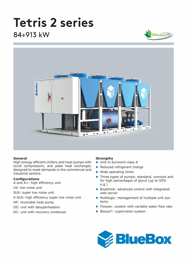
GeneralHigh energy efficient chillers and heat pumps with scroll compressors, and plate heat exchanger, designed to meet demands in the commercial and industrial sectors.
ConfigurationsA and A+: high efficiency unitLN: low noise unitSLN: super low noise unitA SLN: high efficiency super low noise unitHP: reversible heat pumpDS: unit with desuperheatersDC: unit with recovery condenser
Strengths ► Unit in Eurovent class A ► Reduced refrigerant charge ► Wide operating limits ► Three types of pumps: standard, oversize and for high percentages of glycol (up to 50% e.g.)
► Bluethink: advanced control with integrated web server
► Multilogic: management of multiple unit sys-tems
► Flowzer: system with variable water flow rate ► Blueye®: supervision system

1
Tetris 2 series
Product description 3
Description of accessories 8Refrigerant circuit accessories 8Fan accessories 10Hydraulic circuit accessories 11Electrical accessories 15Other accessories 19
Technical specifications 22Tetris 2 22Tetris 2 A 26Tetris 2 SLN 28Tetris 2 A+ 30Tetris 2 A SLN 32
Electrical specifications 34Tetris 2 34Tetris 2 A - Tetris 2 SLN 36Tetris 2 A+ - Tetris 2 A SLN 37
Pump data 38
User-side exchanger flow rate fields 39
Operating limits 40Tetris 2 40Tetris 2 A - Tetris 2 SLN 42Tetris 2 A+ - Tetris 2 A SLN 44
Noise levels 46Tetris 2 46Tetris 2 A - Tetris 2 SLN 48Tetris 2 A+ - Tetris 2 A SLN 49
Configurations that are not possible 50
Installation advice 52Water characteristics 52Glycol mixtures 52Minimum water content in the system 53Installation site 54Installations that require the use of treated coils 55Aeraulic head losses and options available for the ventilating section 56
Dimensional diagrams 57Tetris 2 57Tetris 2 A - Tetris 2 SLN 64Tetris 2 A+ - Tetris 2 A SLN 68

2
3
Tetris 2 seriesHigh energy efficient chillers and heat pumps with scroll compressors, and plate heat exchanger, designed to meet demands in the commercial and industrial sectors.
PRODUCT DESCRIPTIONBODYThe body is modular with a load-bearing frame, made of galvanized sheet-iron coated with polyester powder RAL 5017/7035 which makes it highly resistant to weather conditions. All screws and bolts are stainless steel.
REFRIGERANTThe unit is charged with refrigerant R410A.
COMPRESSORSThe compressors are hermetic orbiting spiral scroll com-pressors connected in tandem or in trio, fitted with oil lev-el sight glass, oil equalization line, crankcase heater and electronic protection.
SOURCE-SIDE HEAT EXCHANGER(excluding HP units)The exchangers are made with microchannel aluminium coils. Finned pack coils with copper tubes and aluminium fins can be requested as accessory.to sophisticated production methods, microchannel coils are made using specific aluminium alloys for the tubes and for the fins. This allows the effects of galvanic corrosion to be drastically reduced to always ensure protection of the tubes that confine the refrigerant. Tubes and fins are also subjected to SilFLUX coating processes (or equivalent) or have zinc added to further increase their corrosion resist-ance.If the unit has to be installed in an environment with a particularly aggressive atmosphere, e-coated microchan-nel coils are available as an option. This option is strongly recommended for applications in coastal or highly indus-trialized areas.The use of microchannel coils compared to convention-al copper/aluminium coils reduces the total weight of the unit by about 10% and gives a reduction in refrigerant charge of at least 30%.The V-shaped arrangement of the coils enables them to be protected from hail and makes the unit compact. It also guarantees an increase in the air intake surface, and leaves ample space for distribution of the components of the refrigerant circuit and the hydraulic circuit.To protect the exchangers from corrosion and ensure opti-mal operation of the unit, we advise following the recom-mendations given in the user, installation and maintenance manual for cleaning the coils. For installations within a kilometre of the coast, use of the accessory is strongly recommended Coil treated with anti-corrosion paints.
SOURCE-SIDE HEAT EXCHANGER(only for HP units)The exchangers are made with finned pack coils with cop-per tubes and aluminium fins.At the base of each coil, there is an Anti-Ice Circuit: this prevents ice formation in the lower part of the coil and therefore allows the unit to operate even with extremely harsh temperatures and with high humidity levels.The V-shaped arrangement of the coils enables them to be protected from hail and makes the unit compact. It also guarantees an increase in the air intake surface, and leaves ample space for distribution of the components of the refrigerant circuit and the hydraulic circuit.To protect the exchangers from corrosion and ensure opti-mal operation of the unit, we advise following the recom-mendations given in the user, installation and maintenance manual for cleaning the coils. For installations within a kilometre of the coast, use of the accessory is strongly recommended Coil treated with anti-corrosion paints.
FANSThe fans are axial fans, directly coupled to a three-phase 6-pole electric motor, with integrated thermal overload protection (klixon) and IP 54 protection rating.The fan includes the shroud, designed to optimize its effi-ciency and reduce noise emission to a minimum, and the safety guard.
USER-SIDE HEAT EXCHANGERThe exchanger is a braze-welded stainless steel plate heat exchanger, insulated with a shroud of closed-cell insulat-ing material.Models with two refrigerant circuits are fitted with dual circuit heat exchanger with a single hydraulic connection.Models with three or four refrigerant circuits are made with two manifolded heat exchangers.Each heat exchanger is equipped with:• a thermostat-controlled anti-freeze heater to protect it
from ice formation when the unit is not running• a temperature probe for freeze protection
REFRIGERANT CIRCUITEach refrigerant circuit of the basic unit (cold only) com-prises:• shut-off valve in the liquid line• 5/16” charging valves• liquid sight glass• replaceable solid cartridge dehydrator filter• electronic expansion valve• pressure transducers for reading the high and low pres-
sure values and relevant evaporating and condensing temperatures
• high pressure switches• low pressure switches (only for models with parametric
control)The pipes of the circuit and the exchanger are insulated with extruded closed-cell expanded elastomer that is re-sistant to UV rays.
4
ELECTRICAL CONTROL PANELThe electrical control panel is made in a painted galva-nized sheet-iron box with forced ventilation and IP54 pro-tection rating.The electrical control panel of the basic unit comprises:• main disconnect switch• automatic circuit breakers for compressors with fixed
calibration• fuses for protecting the fans and auxiliary circuits• thermal magnetic circuit breakers for pumps (if pres-
ent)• contactors for compressors, fans and pumps (if pres-
ent)• phase monitor• potential-free general alarm contacts• single potential free operating contacts for compres-
sors, fans and pumps (if present)• microprocessor controller with display accessible from
the outside• external air temperature probe• summer/winter selection from digital input (only for /
HP unit)All the electrical cables inside the panel are numbered and the terminal board dedicated to the customer's connec-tions is coloured blue so that it can be quickly identified in the panel.Standard power supply of the unit is 400V/3~/50Hz
CONTROL BLUETHINKThe unit is supplied with two types of control according to size and version:• parametric control: Tetris 2 units from model 10.2 to
16.2. For these units, the advanced control can in any case be ordered as an accessory.
• advanced control: all the other set-ups.
Main controller functions parametricThis is the standard control for models from 10.2 to 16.2. For these units, the advanced control can in any case be ordered as an accessory.The control allows the following functions:• water temperature adjustment, with control of the wa-
ter entering the user-side heat exchanger• freeze protection• compressor timings• automatic rotation of compressor starting sequence• recording of the alarm log• digital input for hot circuit ON/OFF• digital input for general ON/OFF• digital input for Summer/Winter selection (only for HP
units)For further details on available functions and on displayed information, you can refer to the specific documentation of the control.By default, the serial connections present as standard are enabled only for reading from BMS. Enabling of writing from BMS is to be requested when ordering.
Main controller functions advancedThe control allows the following functions:• water temperature adjustment, with control of the wa-
ter entering the user-side heat exchanger• freeze protection• compressor timings• automatic rotation of compressor starting sequence• recording of the log of all machine inputs, outputs and
states• automatic rotation of compressor starting sequence• recording of the alarm log• digital input for hot circuit ON/OFF• Ethernet serial port with Modbus protocol and integrat-
ed web server preloaded web page• digital input for general ON/OFF• digital input for Summer/Winter selection (only for HP
units)For further details on available functions and on displayed information, you can refer to the specific documentation of the control.By default, the serial connections present as standard are enabled only for reading from BMS. Enabling of writing from BMS is to be requested when ordering.
Main functions of the webserver (only for units with advanced control)As standard, the Bluethink controller integrates a web-server with a preloaded web page that is accessed via password.The web page allows the following functions to be carried out (some of these are available only for users with ad-vanced level rights):• display of the main functions of the unit such as unit
serial n°, size, refrigerant• display of the general status of the machine: water in-
let and outlet temperatures, external air temperature, mode (chiller or heat pump), evaporating and condens-ing pressures, suction and discharge temperatures
• display of the status of compressors, pumps, expansion valves
• display in real time of the graphs of the main quantities• display of the graphs of logged quantities• display of alarm log• management of users on several levels• remote ON/OFF• remote set point change• remote time band change• remote summer winter mode selection
5
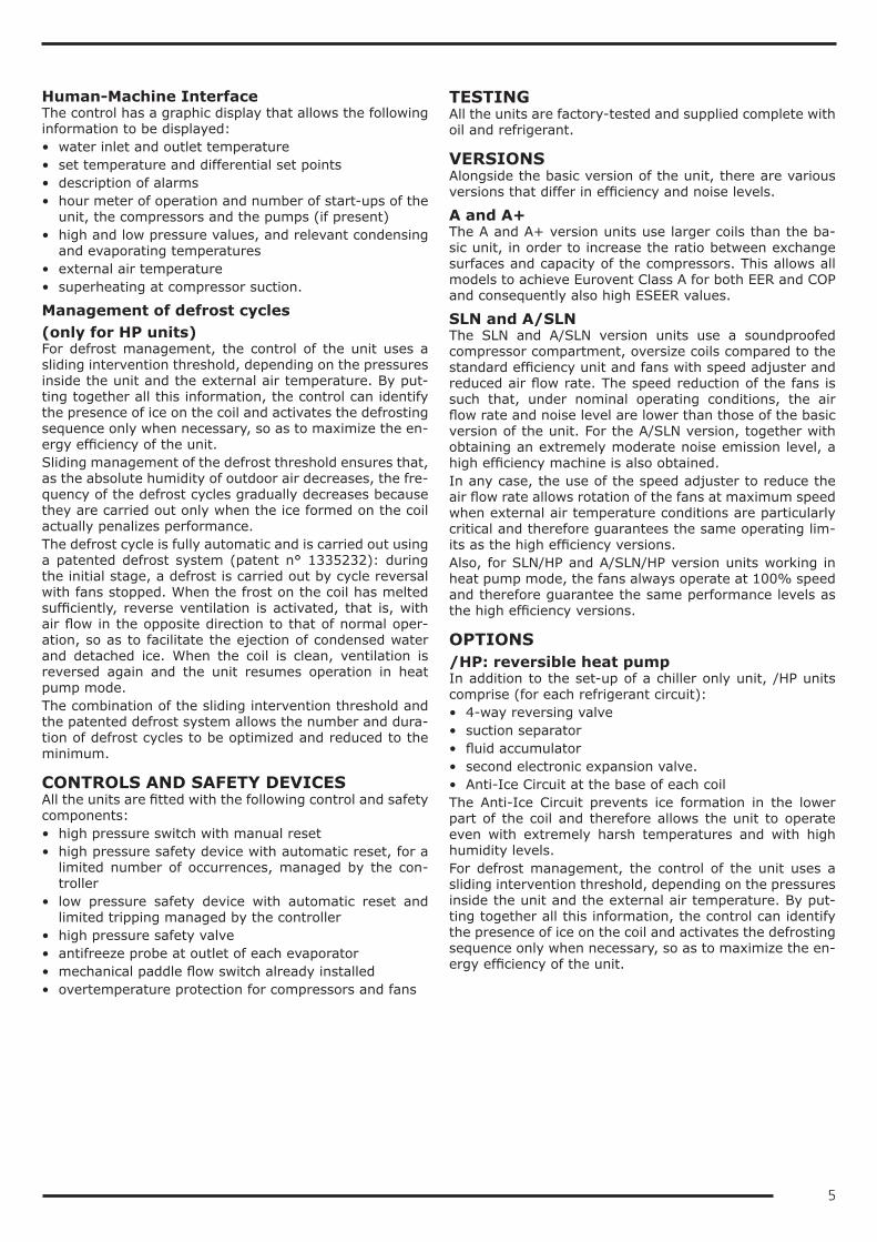
Human-Machine InterfaceThe control has a graphic display that allows the following information to be displayed:• water inlet and outlet temperature• set temperature and differential set points• description of alarms• hour meter of operation and number of start-ups of the
unit, the compressors and the pumps (if present)• high and low pressure values, and relevant condensing
and evaporating temperatures• external air temperature• superheating at compressor suction.
Management of defrost cycles(only for HP units)For defrost management, the control of the unit uses a sliding intervention threshold, depending on the pressures inside the unit and the external air temperature. By put-ting together all this information, the control can identify the presence of ice on the coil and activates the defrosting sequence only when necessary, so as to maximize the en-ergy efficiency of the unit.Sliding management of the defrost threshold ensures that, as the absolute humidity of outdoor air decreases, the fre-quency of the defrost cycles gradually decreases because they are carried out only when the ice formed on the coil actually penalizes performance.The defrost cycle is fully automatic and is carried out using a patented defrost system (patent n° 1335232): during the initial stage, a defrost is carried out by cycle reversal with fans stopped. When the frost on the coil has melted sufficiently, reverse ventilation is activated, that is, with air flow in the opposite direction to that of normal oper-ation, so as to facilitate the ejection of condensed water and detached ice. When the coil is clean, ventilation is reversed again and the unit resumes operation in heat pump mode.The combination of the sliding intervention threshold and the patented defrost system allows the number and dura-tion of defrost cycles to be optimized and reduced to the minimum.
CONTROLS AND SAFETY DEVICESAll the units are fitted with the following control and safety components:• high pressure switch with manual reset• high pressure safety device with automatic reset, for a
limited number of occurrences, managed by the con-troller
• low pressure safety device with automatic reset and limited tripping managed by the controller
• high pressure safety valve• antifreeze probe at outlet of each evaporator• mechanical paddle flow switch already installed• overtemperature protection for compressors and fans
TESTINGAll the units are factory-tested and supplied complete with oil and refrigerant.
VERSIONSAlongside the basic version of the unit, there are various versions that differ in efficiency and noise levels.
A and A+The A and A+ version units use larger coils than the ba-sic unit, in order to increase the ratio between exchange surfaces and capacity of the compressors. This allows all models to achieve Eurovent Class A for both EER and COP and consequently also high ESEER values.
SLN and A/SLNThe SLN and A/SLN version units use a soundproofed compressor compartment, oversize coils compared to the standard efficiency unit and fans with speed adjuster and reduced air flow rate. The speed reduction of the fans is such that, under nominal operating conditions, the air flow rate and noise level are lower than those of the basic version of the unit. For the A/SLN version, together with obtaining an extremely moderate noise emission level, a high efficiency machine is also obtained.In any case, the use of the speed adjuster to reduce the air flow rate allows rotation of the fans at maximum speed when external air temperature conditions are particularly critical and therefore guarantees the same operating lim-its as the high efficiency versions.Also, for SLN/HP and A/SLN/HP version units working in heat pump mode, the fans always operate at 100% speed and therefore guarantee the same performance levels as the high efficiency versions.
OPTIONS/HP: reversible heat pumpIn addition to the set-up of a chiller only unit, /HP units comprise (for each refrigerant circuit):• 4-way reversing valve• suction separator• fluid accumulator• second electronic expansion valve.• Anti-Ice Circuit at the base of each coilThe Anti-Ice Circuit prevents ice formation in the lower part of the coil and therefore allows the unit to operate even with extremely harsh temperatures and with high humidity levels.For defrost management, the control of the unit uses a sliding intervention threshold, depending on the pressures inside the unit and the external air temperature. By put-ting together all this information, the control can identify the presence of ice on the coil and activates the defrosting sequence only when necessary, so as to maximize the en-ergy efficiency of the unit.
6
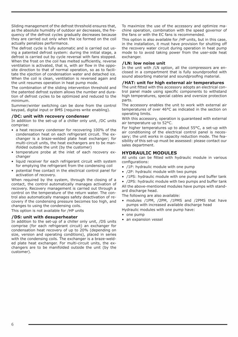
Sliding management of the defrost threshold ensures that, as the absolute humidity of outdoor air decreases, the fre-quency of the defrost cycles gradually decreases because they are carried out only when the ice formed on the coil actually penalizes performance.The defrost cycle is fully automatic and is carried out us-ing a patented defrost system: during the initial stage, a defrost is carried out by cycle reversal with fans stopped. When the frost on the coil has melted sufficiently, reverse ventilation is activated, that is, with air flow in the oppo-site direction to that of normal operation, so as to facili-tate the ejection of condensation water and detached ice. When the coil is clean, ventilation is reversed again and the unit resumes operation in heat pump mode.The combination of the sliding intervention threshold and the patented defrost system allows the number and dura-tion of defrost cycles to be optimized and reduced to the minimum.Summer/winter switching can be done from the control keypad, digital input or BMS (requires write enabling).
/DC: unit with recovery condenserIn addition to the set-up of a chiller only unit, /DC units comprise:• a heat recovery condenser for recovering 100% of the
condensation heat on each refrigerant circuit. The ex-changer is a braze-welded plate heat exchanger; for multi-circuit units, the heat exchangers are to be man-ifolded outside the unit (by the customer)
• temperature probe at the inlet of each recovery ex-changer
• liquid receiver for each refrigerant circuit with system for emptying the refrigerant from the condensing coil
• potential free contact in the electrical control panel for activation of recovery.
When required by the system, through the closing of a contact, the control automatically manages activation of recovery. Recovery management is carried out through a control on the temperature of the return water. The con-trol also automatically manages safety deactivation of re-covery if the condensing pressure becomes too high, and changes to using the condensing coils.This option is not available for /HP units
/DS: unit with desuperheaterIn addition to the set-up of a chiller only unit, /DS units comprise (for each refrigerant circuit) an exchanger for condensation heat recovery of up to 20% (depending on size, version and operating conditions), placed in series with the condensing coils. The exchanger is a braze-weld-ed plate heat exchanger. For multi-circuit units, the ex-changers are to be manifolded outside the unit (by the customer).
To maximize the use of the accessory and optimize ma-chine operation, combination with the speed governor of the fans or with the EC fans is recommended.This option is also available for /HP units, but in this case, in the installation, it must have provision for shutting off the recovery water circuit during operation in heat pump mode to to avoid taking power from the user-side heat exchanger.
/LN: low noise unitIn the unit with /LN option, all the compressors are en-closed in a compartment that is fully soundproofed with sound absorbing material and soundproofing material.
/HAT: unit for high external air temperaturesThe unit fitted with this accessory adopts an electrical con-trol panel made using specific components to withstand high temperatures, special cables and oversize protection parts.The accessory enables the unit to work with external air temperatures of over 46°C as indicated in the section on operating limits.With this accessory, operation is guaranteed with external air temperature up to 52°C.For higher temperatures up to about 55°C, a set-up with air conditioning of the electrical control panel is neces-sary; the unit works in capacity reduction mode. The fea-sibility of this set-up must be assessed: please contact our sales department.
HYDRAULIC MODULESAll units can be fitted with hydraulic module in various configurations:• /1P: hydraulic module with one pump• /2P: hydraulic module with two pumps• /1PS: hydraulic module with one pump and buffer tank• /2PS: hydraulic module with two pumps and buffer tankAll the above-mentioned modules have pumps with stand-ard discharge head.The following are also available:• modules /1PM, /2PM, /1PMS and /2PMS that have
pumps with increased available discharge headHydraulic modules with one pump have:• one pump• an expansion vessel
7
Hydraulic modules with two pumps have:• two pumps• a check valve on the delivery side of each pump• an expansion vesselIn the version with 2 pumps, these are always with one on standby while the other is working. Switching over be-tween the pumps is automatic and is done by time (to balance the hours of operation of each one) or in the event of failure.Hydraulic modules with three pumps have:• three pumps• a check valve on the delivery side of each pump• an expansion vesselThe 3 pumps operate in parallel and each one processes a third of the total flow rate. If one of the three pumps fails, the unit will work in forced capacity reduction mode (to avoid low pressure alarms) and the remaining two pumps will in any case be able to guarantee about 78% of the rated flow rate.Hydraulic modules with tank also have:• a gate valve at the inlet of the pump or the suction
manifold• a tank with drain valve and air valveRefer to the table of configurations that are not possible to check for availability of specific set-ups.
8
DESCRIPTION OF ACCESSORIESRefrigerant circuit accessoriesBC Capacitive backup battery for electronic expansion valve
When the compressors stop, the controller always closes the electronic expansion valve to prevent dangerous refrigerant migration. The presence of the backup battery ensures that the electronic valve is kept in closed position even when there is no power supplyThis accessory uses a condenser, and not an ordinary battery, as energy storage: this allows it to be unaffected by the memory effect of normal batteries and eliminates its need for maintenance.
BT Backup battery for electronic expansion valveWhen the compressors stop, the controller always closes the electronic expansion valve to prevent dangerous refrigerant migration. The presence of the backup battery ensures that the electronic valve is kept in closed position even when there is no power supply
BK Brine KitThis accessory is compulsory if a water temperature set point lower than +3°C is used (if the unit is provided with double set point or variable set point, the lower set point is considered).The accessory consists of increased insulation and suitable sizing and calibration of some components.The inlet and outlet temperatures of the user-side exchanger must be given on ordering to allow correct set-ting of the alarm parameters and verification of the sizing of the expansion valve.The cooling set point can then be changed by the customer in an interval that, compared to the set point given on ordering, ranges from -1K up to the maximum temperature allowed by the above-stated operating limits.The unit will be optimized to work at the set point temperature given on ordering. For different set points, the cooling capacity provided and the level of efficiency of the machine could decrease and move away from these conditions.This accessory compulsorily requires the insertion of one of the options: condensing control with speed ad-juster or EC fans.
DVS Double safety valveWith this accessory, instead of each individual safety valve per circuit, there is a "candelabrum" with two safety valves and a diverter valve for choosing the valve in operation. This allows the safety valves to be replaced without having to drain the machine and without having to stop it.
MAFR Pressure gaugesThe operating pressures of each circuit of the unit can be displayed on the control by accessing the relevant screens. Also, the machine can be fitted with pressure gauges (two for each circuit) installed in a clearly visible position. These allow reading in real time of the working pressures of the refrigerant gas on the low pressure side and on the high pressure side of each refrigerant circuit.
RG Condensation control with fan speed governorThe control manages the speed of the fans through a phase cutting speed governor, in order to optimize the operating conditions and efficiency of the unit.This control also has the effect of reducing the noise level of the unit: in fact, the typical conditions under which the control will be modulating the speed of the fans are those of the night, spring and autumn.For units equipped with EC fans, the same function is carried out using the electronically commutated motor of the fans and is supplied as standard.
RIC Liquid receiverThe adoption of this accessory always guarantees correct feeding of the expansion valve even when the unit is subjected to wide external air temperature ranges.This accessory is standard on DC and HP units.

9
RPP Refrigerant leak detector with automatic pump downWith this accessory, a refrigerant leak detector is placed inside each compressor compartment. Detection of a refrigerant leak is managed by the control through a specific alarm and display of a specific icon on the display of the control. For all the circuits of the unit, the alarm also starts the machine stopping procedure with pump down, confining all the refrigerant in the coils.The accessory includes the capacitive backup battery.The accessory can be applied only to units in LN or SLN set-up.
RPR Refrigerant leak detectorWith this accessory, a refrigerant leak detector is placed inside each compressor compartment. Detection of a refrigerant leak is managed by the controller through a specific alarm and display of a specific icon on the display of the controller. This alarm stops the unit.The accessory can be applied only to units in LN or SLN set-up.
RUB Compressor suction and delivery valvesThe valves situated on the delivery side and on the suction side of the compressors allow the compressor to be isolated from the rest of the refrigerant circuit, so making the maintenance operations quicker and less invasive
10
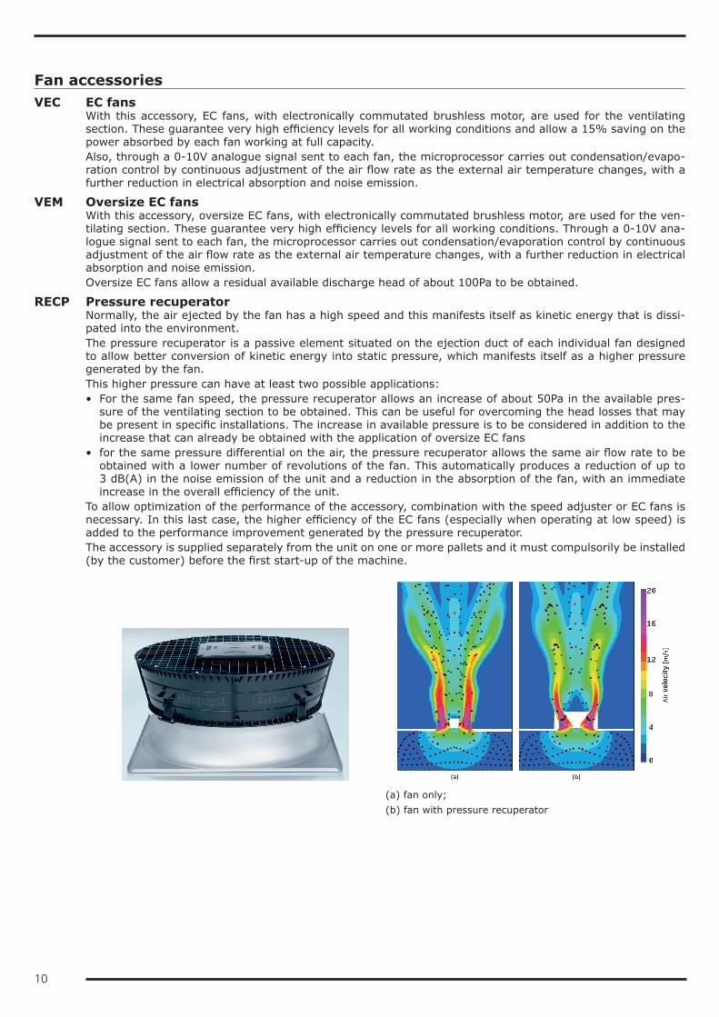
Fan accessoriesVEC EC fans
With this accessory, EC fans, with electronically commutated brushless motor, are used for the ventilating section. These guarantee very high efficiency levels for all working conditions and allow a 15% saving on the power absorbed by each fan working at full capacity.Also, through a 0-10V analogue signal sent to each fan, the microprocessor carries out condensation/evapo-ration control by continuous adjustment of the air flow rate as the external air temperature changes, with a further reduction in electrical absorption and noise emission.
VEM Oversize EC fansWith this accessory, oversize EC fans, with electronically commutated brushless motor, are used for the ven-tilating section. These guarantee very high efficiency levels for all working conditions. Through a 0-10V ana-logue signal sent to each fan, the microprocessor carries out condensation/evaporation control by continuous adjustment of the air flow rate as the external air temperature changes, with a further reduction in electrical absorption and noise emission.Oversize EC fans allow a residual available discharge head of about 100Pa to be obtained.
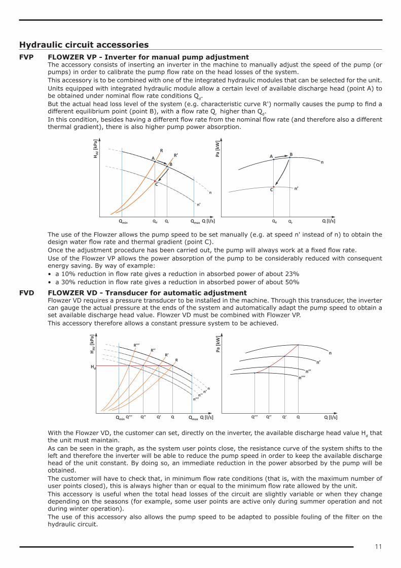
RECP Pressure recuperatorNormally, the air ejected by the fan has a high speed and this manifests itself as kinetic energy that is dissi-pated into the environment.The pressure recuperator is a passive element situated on the ejection duct of each individual fan designed to allow better conversion of kinetic energy into static pressure, which manifests itself as a higher pressure generated by the fan.This higher pressure can have at least two possible applications:• For the same fan speed, the pressure recuperator allows an increase of about 50Pa in the available pres-
sure of the ventilating section to be obtained. This can be useful for overcoming the head losses that may be present in specific installations. The increase in available pressure is to be considered in addition to the increase that can already be obtained with the application of oversize EC fans
• for the same pressure differential on the air, the pressure recuperator allows the same air flow rate to be obtained with a lower number of revolutions of the fan. This automatically produces a reduction of up to 3 dB(A) in the noise emission of the unit and a reduction in the absorption of the fan, with an immediate increase in the overall efficiency of the unit.
To allow optimization of the performance of the accessory, combination with the speed adjuster or EC fans is necessary. In this last case, the higher efficiency of the EC fans (especially when operating at low speed) is added to the performance improvement generated by the pressure recuperator.The accessory is supplied separately from the unit on one or more pallets and it must compulsorily be installed (by the customer) before the first start-up of the machine.
(a) fan only;(b) fan with pressure recuperator
11
Hydraulic circuit accessoriesFVP FLOWZER VP - Inverter for manual pump adjustment
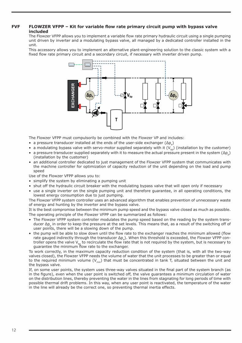
The accessory consists of inserting an inverter in the machine to manually adjust the speed of the pump (or pumps) in order to calibrate the pump flow rate on the head losses of the system.This accessory is to be combined with one of the integrated hydraulic modules that can be selected for the unit.Units equipped with integrated hydraulic module allow a certain level of available discharge head (point A) to be obtained under nominal flow rate conditions Qd.But the actual head loss level of the system (e.g. characteristic curve R') normally causes the pump to find a different equilibrium point (point B), with a flow rate Qr higher than Qd.In this condition, besides having a different flow rate from the nominal flow rate (and therefore also a different thermal gradient), there is also higher pump power absorption.
QrQd Q [l/s]
n’
Qmin
n
Qmax
HAV
[kPa
]
n
n’
Pa [k
W]
Q [l/s]
RR’
Qd Qr
A B
C
AB
C
The use of the Flowzer allows the pump speed to be set manually (e.g. at speed n' instead of n) to obtain the design water flow rate and thermal gradient (point C).Once the adjustment procedure has been carried out, the pump will always work at a fixed flow rate.Use of the Flowzer VP allows the power absorption of the pump to be considerably reduced with consequent energy saving. By way of example:• a 10% reduction in flow rate gives a reduction in absorbed power of about 23%• a 30% reduction in flow rate gives a reduction in absorbed power of about 50%
FVD FLOWZER VD - Transducer for automatic adjustmentFlowzer VD requires a pressure transducer to be installed in the machine. Through this transducer, the inverter can gauge the actual pressure at the ends of the system and automatically adapt the pump speed to obtain a set available discharge head value. Flowzer VD must be combined with Flowzer VP.This accessory therefore allows a constant pressure system to be achieved.
Q [l/s]
R
n’’’n’’
n’
Qmin
n
Qmax
HAV
[kPa
]
Hd
R’R’’
R’’’
Q’’’ Q’’ Q’ Q
Pa [k
W]
Q’’’ Q’’ Q’ Q
n
n’
n’’n’’’
Q [l/s]
With the Flowzer VD, the customer can set, directly on the inverter, the available discharge head value Hd that the unit must maintain.As can be seen in the graph, as the system user points close, the resistance curve of the system shifts to the left and therefore the inverter will be able to reduce the pump speed in order to keep the available discharge head of the unit constant. By doing so, an immediate reduction in the power absorbed by the pump will be obtained.The customer will have to check that, in minimum flow rate conditions (that is, with the maximum number of user points closed), this is always higher than or equal to the minimum flow rate allowed by the unit.This accessory is useful when the total head losses of the circuit are slightly variable or when they change depending on the seasons (for example, some user points are active only during summer operation and not during winter operation).The use of this accessory also allows the pump speed to be adapted to possible fouling of the filter on the hydraulic circuit.
12
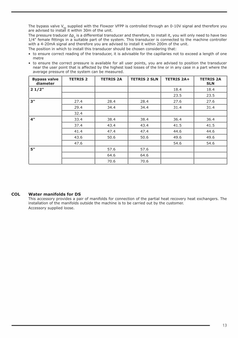
FVF FLOWZER VFPP – Kit for variable flow rate primary circuit pump with bypass valve includedThe Flowzer VFPP allows you to implement a variable flow rate primary hydraulic circuit using a single pumping unit driven by inverter and a modulating bypass valve, all managed by a dedicated controller installed in the unit.This accessory allows you to implement an alternative plant-engineering solution to the classic system with a fixed flow rate primary circuit and a secondary circuit, if necessary with inverter driven pump.
ΔppΔpe
EXC
HAN
GER
Vbp
T
The Flowzer VFPP must compulsorily be combined with the Flowzer VP and includes:• a pressure transducer installed at the ends of the user-side exchanger (Δpe)• a modulating bypass valve with servo-motor supplied separately with it (Vbp) (installation by the customer)• a pressure transducer supplied separately with it to measure the actual pressure present in the system (Δpp)
(installation by the customer)• an additional controller dedicated to just management of the Flowzer VFPP system that communicates with
the machine controller for optimization of capacity reduction of the unit depending on the load and pump speed
Use of the Flowzer VFPP allows you to:• simplify the system by eliminating a pumping unit• shut off the hydraulic circuit breaker with the modulating bypass valve that will open only if necessary• use a single inverter on the single pumping unit and therefore guarantee, in all operating conditions, the
lowest energy consumption due to just pumping.The Flowzer VFPP system controller uses an advanced algorithm that enables prevention of unnecessary waste of energy and hunting by the inverter and the bypass valve.It is the best compromise between the minimum pump speed and the bypass valve closed as much as possible.The operating principle of the Flowzer VFPP can be summarized as follows:• The Flowzer VFPP system controller modulates the pump speed based on the reading by the system trans-
ducer Δpp in order to keep the pressure at the set levels. This means that, as a result of the switching off of user points, there will be a slowing down of the pump.
• the pump will be able to slow down until the flow rate to the exchanger reaches the minimum allowed (flow rate gauged indirectly through the transducer Δpe). When this threshold is exceeded, the Flowzer VFPP con-troller opens the valve Vbp to recirculate the flow rate that is not required by the system, but is necessary to guarantee the minimum flow rate to the exchanger.
To work correctly, in the maximum capacity reduction condition of the system (that is, with all the two-way valves closed), the Flowzer VFPP needs the volume of water that the unit processes to be greater than or equal to the required minimum volume (Vmin) that must be concentrated in tank T, situated between the unit and the bypass valve.If, on some user points, the system uses three-way valves situated in the final part of the system branch (as in the figure), even when the user point is switched off, the valve guarantees a minimum circulation of water on the distribution lines, thereby preventing the water in the lines from stagnating for long periods of time with possible thermal drift problems. In this way, when any user point is reactivated, the temperature of the water in the line will already be the correct one, so preventing thermal inertia effects.
13
The bypass valve Vbp supplied with the Flowzer VFPP is controlled through an 0-10V signal and therefore you are advised to install it within 30m of the unit.The pressure traducer Δpp is a differential transducer and therefore, to install it, you will only need to have two 1/4" female fittings in a suitable part of the system. This transducer is connected to the machine controller with a 4-20mA signal and therefore you are advised to install it within 200m of the unit.The position in which to install this transducer should be chosen considering that:• to ensure correct reading of the transducer, it is advisable for the capillaries not to exceed a length of one
metre• to ensure the correct pressure is available for all user points, you are advised to position the transducer
near the user point that is affected by the highest load losses of the line or in any case in a part where the average pressure of the system can be measured.
Bypass valve diameter
TETRIS 2 TETRIS 2A TETRIS 2 SLN TETRIS 2A+ TETRIS 2A SLN
2 1/2" 18.4 18.4 23.5 23.5
3" 27.4 28.4 28.4 27.6 27.629.4 34.4 34.4 31.4 31.432.4
4" 33.4 38.4 38.4 36.4 36.437.4 43.4 43.4 41.5 41.541.4 47.4 47.4 44.6 44.643.6 50.6 50.6 49.6 49.647.6 54.6 54.6
5" 57.6 57.6 64.6 64.6 70.6 70.6
COL Water manifolds for DSThis accessory provides a pair of manifolds for connection of the partial heat recovery heat exchangers. The installation of the manifolds outside the machine is to be carried out by the customer.Accessory supplied loose.
14
PFP User-side pump with Pulse functionAs standard, the unit is set to keep the system-side circulation pump on all the time, even when the set point temperature is reached.But when the unit is provided with this accessory, on reaching the set point, the controller will switch off the pump and start it again at regular intervals for a sufficient time to measure the water temperature. If the controller verifies that the water temperature is still in set point condition, it will switch off the pump again. Otherwise the controller will start the compressors again to meet the requirements of the system.This accessory therefore allows electrical absorption due to pumping to be drastically reduced, especially in spring and autumn when the load is extremely low.
RA Antifreeze heater …These are electric heaters inserted on the user-side heat exchanger, on the pumps and in the tank (depending on the configuration of the machine) to prevent damage to the hydraulic components due to ice formation during periods when the machine is stopped.Based on normal operating conditions and the percentage of glycol in the system, an appropriate “antifreeze alarm” temperature is set in the control. When a temperature that is 1K higher than the antifreeze alarm threshold is detected at the outlet from the exchanger, the pump (if present) and the antifreeze heaters are switched on. If the temperature of the outgoing water reaches the antifreeze alarm threshold, the compres-sors are stopped, keeping the heaters and the pumps active, and the general alarm contact of the machine is activated.
VSIW Water-side safety valveWith this accessory, a safety valve is inserted in the hydraulic circuit of the unit: when the calibration pressure is reached, the valve opens and, by discharging (to be routed by the customer), prevents the system pressure from reaching limits that are dangerous for the components present in the system. The valves have positive action, that is, performance is guaranteed even if the diaphragm deteriorates or breaks.
15
Electrical accessoriesARU Stopping of the unit due to temperatures below the operating limit
With this accessory, it is possible to set the unit so that the controller switches off the compressors when the unit is operating in heat pump mode and the external air temperature falls below a minimum set limit: this will prevent the unit from going into low pressure alarm, so avoiding having to manually restart the machine.At the same time, the control will enable a digital output that can be used for activating an auxiliary heat source.When the external air temperature returns above the set threshold temperature, the unit will automatically resume operation without it being necessary to do anything.For units equipped with integrated pump, the pump will always be kept running so as to prevent ice formation and ensure correct reading of the temperature and antifreeze safety probes at all times.The stopping temperature must be set based on the set point temperature and in accordance with what is allowed by the operating limits of the machine.The same function can be used to set an external air temperature below which to use an alternative heat source because it is more efficient or economically more advantageous.With the default programming, the limit that considers a production of outgoing water at 45°C is set, there-fore:• -7°C for standard units• -10°C for /HE and /SLN units.
COTW Outgoing water temperature controlWith this accessory, outgoing instead of incoming water temperature control is used.
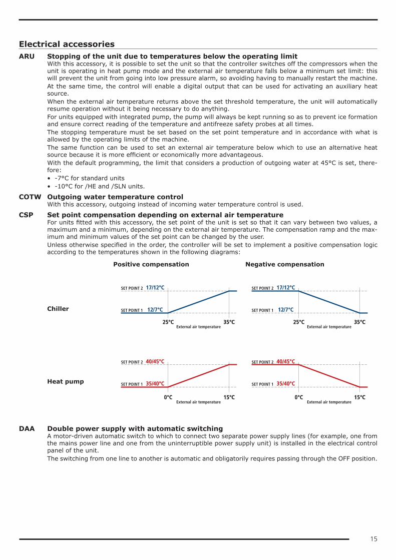
CSP Set point compensation depending on external air temperatureFor units fitted with this accessory, the set point of the unit is set so that it can vary between two values, a maximum and a minimum, depending on the external air temperature. The compensation ramp and the max-imum and minimum values of the set point can be changed by the user.Unless otherwise specified in the order, the controller will be set to implement a positive compensation logic according to the temperatures shown in the following diagrams:
Positive compensation Negative compensation
Chiller
Heat pump
SET POINT 2 17/12°C
SET POINT 1 12/7°C
25°C 35°C
SET POINT 2 17/12°C
SET POINT 1 12/7°C
25°C 35°C
SET POINT 2 40/45°C
SET POINT 1 35/40°C
0°C 15°C
SET POINT 2 40/45°C
SET POINT 1 35/40°C
0°C 15°C External air temperature External air temperature
External air temperature External air temperature
DAA Double power supply with automatic switchingA motor-driven automatic switch to which to connect two separate power supply lines (for example, one from the mains power line and one from the uninterruptible power supply unit) is installed in the electrical control panel of the unit.The switching from one line to another is automatic and obligatorily requires passing through the OFF position.
16
DAM Double power supply with manual switchingA manual switch to which to connect two separate power supply lines (for example, one from the mains power line and one from the uninterruptible power supply unit) is installed in the electrical control panel of the unit.The switching from one line to another is manual and obligatorily requires passing through the OFF position.When this accessory is requested, the power supply of the unit must compulsorily include neutral.
GLO Modbus Lonworks GatewayWith this accessory, a RS485/Lon gateway is installed inside the electrical control panel.By default, the programming gives read-only access to the control of the unit. Enabling of read/write access should be requested when ordering.
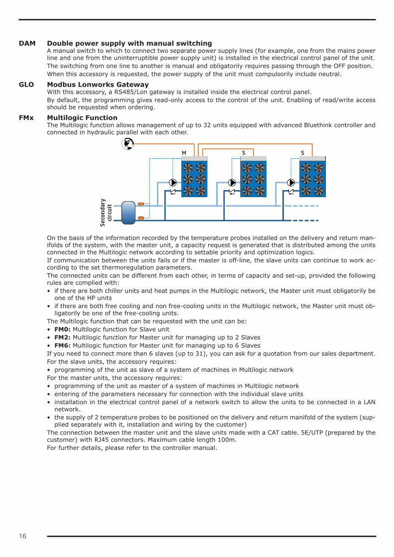
FMx Multilogic FunctionThe Multilogic function allows management of up to 32 units equipped with advanced Bluethink controller and connected in hydraulic parallel with each other.
On the basis of the information recorded by the temperature probes installed on the delivery and return man-ifolds of the system, with the master unit, a capacity request is generated that is distributed among the units connected in the Multilogic network according to settable priority and optimization logics.If communication between the units fails or if the master is off-line, the slave units can continue to work ac-cording to the set thermoregulation parameters.The connected units can be different from each other, in terms of capacity and set-up, provided the following rules are complied with:• if there are both chiller units and heat pumps in the Multilogic network, the Master unit must obligatorily be
one of the HP units• if there are both free cooling and non free-cooling units in the Multilogic network, the Master unit must ob-
ligatorily be one of the free-cooling units.The Multilogic function that can be requested with the unit can be:• FM0: Multilogic function for Slave unit• FM2: Multilogic function for Master unit for managing up to 2 Slaves• FM6: Multilogic function for Master unit for managing up to 6 SlavesIf you need to connect more than 6 slaves (up to 31), you can ask for a quotation from our sales department.For the slave units, the accessory requires:• programming of the unit as slave of a system of machines in Multilogic networkFor the master units, the accessory requires:• programming of the unit as master of a system of machines in Multilogic network• entering of the parameters necessary for connection with the individual slave units• installation in the electrical control panel of a network switch to allow the units to be connected in a LAN
network.• the supply of 2 temperature probes to be positioned on the delivery and return manifold of the system (sup-
plied separately with it, installation and wiring by the customer)The connection between the master unit and the slave units made with a CAT cable. 5E/UTP (prepared by the customer) with RJ45 connectors. Maximum cable length 100m.For further details, please refer to the controller manual.
17
IACV Automatic circuit breakersWith this accessory, automatic circuit breakers are installed instead of fuses for the protection of auxiliary loads. Also, the same accessory uses automatic circuit breakers with adjustable thermal overload protection to protect the compressors.
LIID Limitation of the current absorbed by digital inputWhen this accessory is requested, a digital input is prepared in the terminal board to activate the forced ca-pacity reduction of the unit to a set fixed level.This accessory is useful when there is a need to necessarily limit the power absorbed by the unit as regards particular conditions.We point out that, in some conditions (for example, during defrosting, oil return cycles or hourly compressor rotation procedures), the controller could force the unit to operate at full capacity for limited periods of time.
NSS Night Shift SystemThis accessory is applied to high efficiency /LN version units with speed governor or to SLN units.In the day time slot, which is normally the one with the highest heat load, priority is given to efficiency and therefore the machine works with a fan control curve that maximises the EER. In this time slot, therefore, the unit is a high efficiency low noise machine (equivalent to A/LN, A+/LN)In the night time band (or in any case from time band decided by the customer), the priority changes to limit-ing the noisiness of the machine and therefore the controller carries out an adjustment of the control ramp of the condensing fans, thereby reducing the air flow rate and consequently the noise emission level. So, in this time band, the unit is a super low noise machine (equivalent to SLN).In any case, if there is a need for additional cooling capacity, the controller will manage the demand, if neces-sary, by accelerating the fans and keeping condensation within the correct operating limits.The time slots can be set from the control depending on installation requirements.When the unit is working in heat pump mode, in order to maximise the COP and to obtain the widest possible operating limits, the control of the unit forces the fans to the maximum speed also during the night time bands.
PBA BACnet protocol over IP (Ethernet)The controller is set for use, in read and write mode, of the BACnet port on IP protocol.By default, the programming gives read-only access to the control of the unit. Enabling of read/write access should be requested when ordering.
RE1P Relay for management of 1 external pumpThis accessory can be requested for units without pumps and allows a pump outside the machine to be con-trolled.
RE2P Relay for management of 2 external pumpsThis accessory can be requested for units without pumps and allows two pumps outside the machine to be controlled with a running/stand-by logic by implementing a rotation on the hours of operation.
RIF Power factor correction to cosφ ≥ 0.9With this accessory, an electrical control panel, containing power factor correction condensers to bring the cosφ of the unit to being greater than 0.95, is supplied loose. The condensers should be connected (by the customer) to the electrical control panel of the unit in the specially prepared terminal board.Besides reducing the absorbed reactive power, the use of this accessory also allows the maximum absorbed current to be lowered.
RMMT Maximum and minimum voltage relayThis accessory constantly monitors the voltage value and the unit's power supply phase sequence. If the sup-ply voltage does not fall within the set parameters or there is a phase reversal, an alarm is generated that stops the machine to prevent damage to its main parts
18
SETD Double set point from digital inputThe accessory allows you to preset two different operating set points and manage the change from one to the other through a digital signal.The set point temperatures must be specified when ordering. For optimization of the unit, reference will be made to the lower set point in chiller mode and the higher set point in heat pump mode.Unless otherwise specified in the order, the controller will be set at the factory with the following temperatures:• in chiller mode, set point 1 to 7°C and set point 2 to 12°C• in heat pump mode (only for HP units) set point 1 to 45°C and set point 2 to 40°C
SETV Variable set point with remote signalThe accessory allows the set point to be varied continuously between two preset values, a maximum and a minimum, depending on an external signal that can be of the 0-1V, 0-10V or 4-20mA type.The set point temperatures and the type of signal to use for the adjustment must be specified when ordering. For optimization of the unit, reference will be made to the lower set point in chiller mode and the higher set point in heat pump mode.Unless otherwise specified in the order, the controller will be set at the factory with 0-10V analogue input and with the following temperatures:• in chiller mode, 0V will correspond to a set point of 7°C and 10V will correspond to a set point of 12°C• in heat pump mode (only for HP units), 0V will correspond to a set point of 45°C and 10V will correspond
to a set point of 40°C
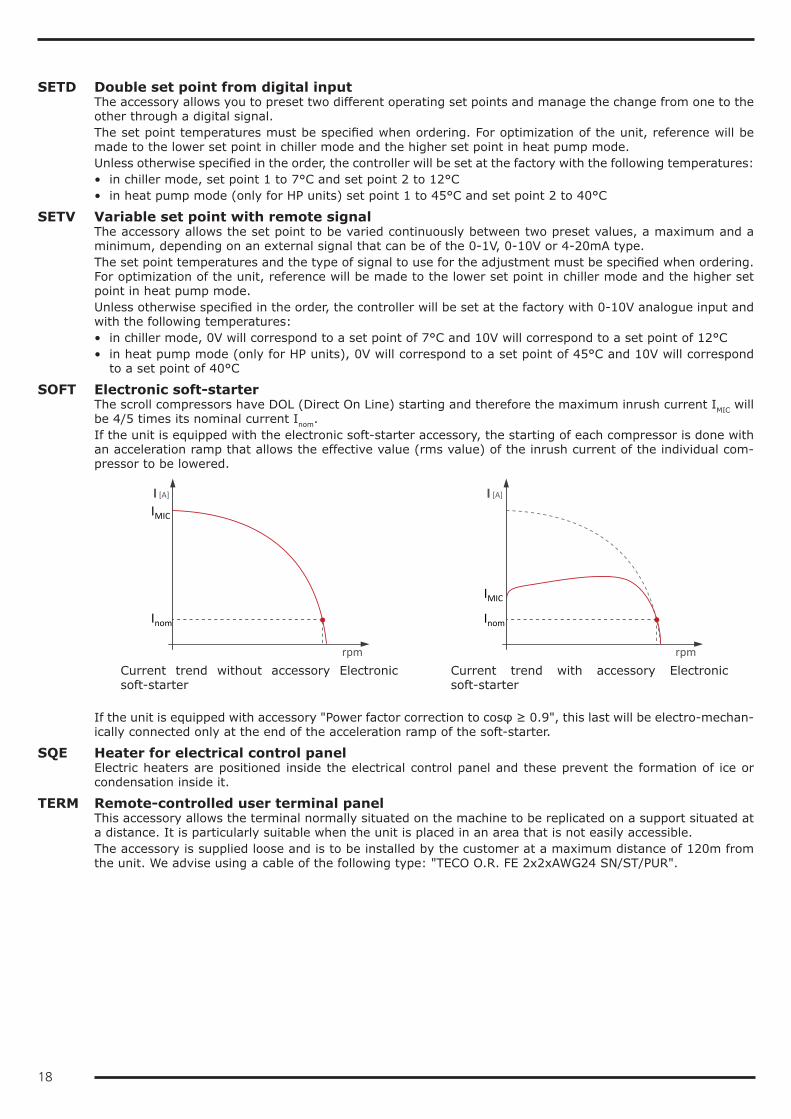
SOFT Electronic soft-starterThe scroll compressors have DOL (Direct On Line) starting and therefore the maximum inrush current IMIC will be 4/5 times its nominal current Inom.If the unit is equipped with the electronic soft-starter accessory, the starting of each compressor is done with an acceleration ramp that allows the effective value (rms value) of the inrush current of the individual com-pressor to be lowered.
rpm
I [A]
Inom
IMIC
rpm
I [A]
IMIC
Inom
Current trend without accessory Electronic soft-starter
Current trend with accessory Electronic soft-starter
If the unit is equipped with accessory "Power factor correction to cosφ ≥ 0.9", this last will be electro-mechan-ically connected only at the end of the acceleration ramp of the soft-starter.
SQE Heater for electrical control panelElectric heaters are positioned inside the electrical control panel and these prevent the formation of ice or condensation inside it.
TERM Remote-controlled user terminal panelThis accessory allows the terminal normally situated on the machine to be replicated on a support situated at a distance. It is particularly suitable when the unit is placed in an area that is not easily accessible.The accessory is supplied loose and is to be installed by the customer at a maximum distance of 120m from the unit. We advise using a cable of the following type: "TECO O.R. FE 2x2xAWG24 SN/ST/PUR".
19
Other accessoriesAG Rubber anti-vibration mounts
These allow you to reduce the vibrations transmitted from the unit to the surface it is standing on.Accessory supplied loose.
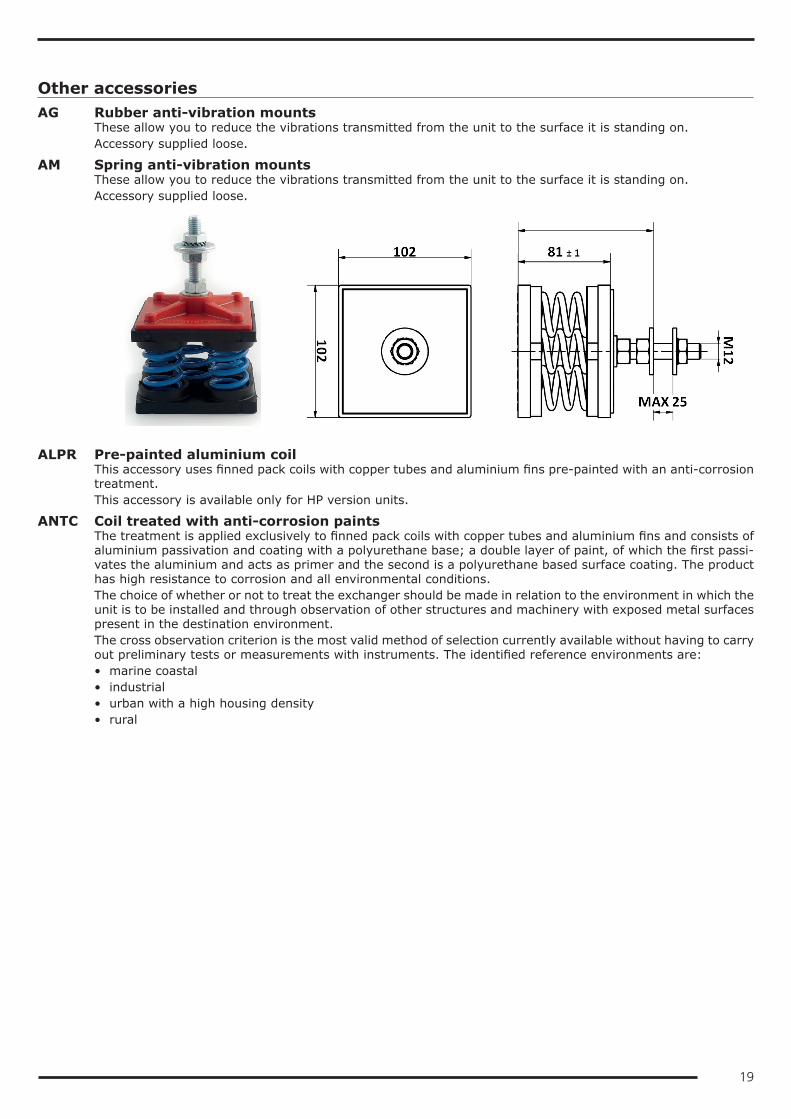
AM Spring anti-vibration mountsThese allow you to reduce the vibrations transmitted from the unit to the surface it is standing on.Accessory supplied loose.
ALPR Pre-painted aluminium coilThis accessory uses finned pack coils with copper tubes and aluminium fins pre-painted with an anti-corrosion treatment.This accessory is available only for HP version units.
ANTC Coil treated with anti-corrosion paintsThe treatment is applied exclusively to finned pack coils with copper tubes and aluminium fins and consists of aluminium passivation and coating with a polyurethane base; a double layer of paint, of which the first passi-vates the aluminium and acts as primer and the second is a polyurethane based surface coating. The product has high resistance to corrosion and all environmental conditions.The choice of whether or not to treat the exchanger should be made in relation to the environment in which the unit is to be installed and through observation of other structures and machinery with exposed metal surfaces present in the destination environment.The cross observation criterion is the most valid method of selection currently available without having to carry out preliminary tests or measurements with instruments. The identified reference environments are:• marine coastal• industrial• urban with a high housing density• rural
20
Please note that in cases where different conditions co-exist, even for short periods, the choice must be suit-able for preserving the exchanger in the harsher environmental conditions and not in conditions between the worst and best situation.Particular attention must be given to cases where an environment that is not particularly aggressive becomes aggressive as a consequence of a local and/or temporal concomitant cause such as, for example, due to the presence of a heating flue outlet or an industrial kitchen or a solvent extraction fan in a small craft business.Protective treatment of the exchanger is strongly recommended if at least one of the points below is verified:• there are obvious signs of corrosion of the exposed metal surfaces in the installation area• the distance from the coast is less than 20 km• the prevailing winds come from the sea towards the unit• the environment is industrial with a significant concentration of pollutants• the environment is urban with a high population density• the environment is rural with the presence of organic discharges and effluents.For chiller units, this accessory also includes the “Cu/Al coil” accessory.
FW Water filterTo protect the elements of the hydraulic circuit (in particular, the exchangers), there are Y filters that can stop and settle the particles that are normally present in the water flow and would otherwise settle in the more delicate parts of the hydraulic circuit and damage its heat exchange capacity.Installation of the water filter is mandatory even when it is not supplied as an accessory.Accessory supplied loose.
MCHE E-coated microchannel coilThe e-coated microchannel coils are treated by immersion of the whole exchanger in an emulsion of organic resins, solvents, ionic stabilisers and deionised water. This is all subjected to a suitable electric field that causes the formation of a solid, uniform deposit on the exchanger. The function of this deposit will be to protect the aluminium from corrosion without penalising its thermophysical properties.The choice of whether or not to treat the exchanger should be made in relation to the environment in which the unit is to be installed and through observation of other structures and machinery with exposed metal surfaces present in the destination environment.The cross observation criterion is the most valid method of selection currently available without having to carry out preliminary tests or measurements with instruments. The identified reference environments are:• marine coastal• industrial• urban with a high housing density• ruralPlease note that in cases where different conditions co-exist, even for short periods, the choice must be suit-able for preserving the exchanger in the harsher environmental conditions and not in conditions between the worst and best situation.Particular attention must be given to cases where an environment that is not particularly aggressive becomes aggressive as a consequence of a local and/or temporal concomitant cause such as, for example, due to the presence of a heating flue outlet or an industrial kitchen or a solvent extraction fan in a small craft business.Protective treatment of the exchanger is strongly recommended if at least one of the points below is verified:• there are obvious signs of corrosion of the exposed metal surfaces in the installation area• the prevailing winds come from the sea towards the unit• the environment is industrial with a significant concentration of pollutants• the environment is urban with a high population density• the environment is rural with the presence of organic discharges and effluents.
21
PRAC Steel profiles frames for container shipmentThis accessory foresees the mounting of steel profiles frames on the unit for its loading into container.When this accessory is required it’s for the shipping of the unit into container and its loading is mandatory to be done at the factory
PREA Unit suitable to be disassembled on siteThe unit is delivered so that it can be disassembled easily on site if this makes the installation operations easier.A unit requested with this option is supplied:• screwed instead of riveted• with plugged and not welded pipes• without refrigerant charge• untested• covered by the warranty only if reassembled and screwed together by personnel authorized by the factory
RAAL Cu/Al coilsThis accessory uses finned pack coils with copper tubes and aluminium fins instead of microchannel coils.
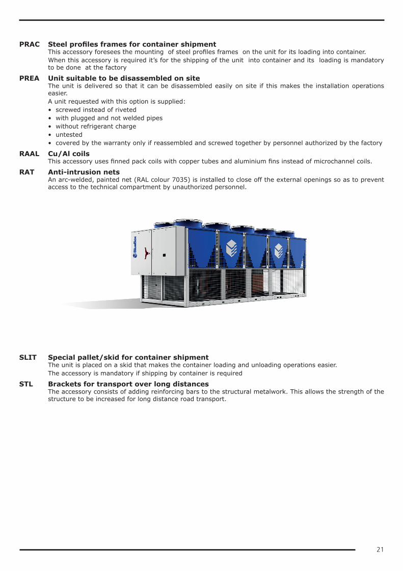
RAT Anti-intrusion netsAn arc-welded, painted net (RAL colour 7035) is installed to close off the external openings so as to prevent access to the technical compartment by unauthorized personnel.
SLIT Special pallet/skid for container shipmentThe unit is placed on a skid that makes the container loading and unloading operations easier.The accessory is mandatory if shipping by container is required
STL Brackets for transport over long distancesThe accessory consists of adding reinforcing bars to the structural metalwork. This allows the strength of the structure to be increased for long distance road transport.
22
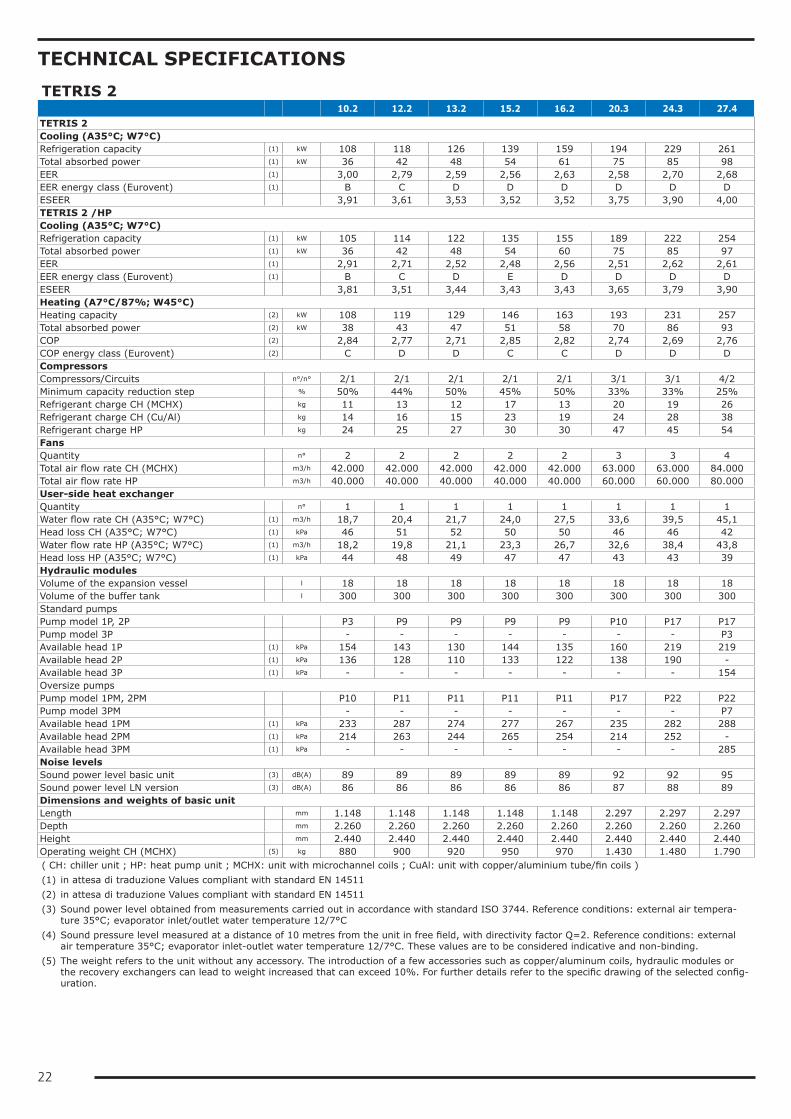
TECHNICAL SPECIFICATIONSTETRIS 2 10.2 12.2 13.2 15.2 16.2 20.3 24.3 27.4TETRIS 2Cooling (A35°C; W7°C)Refrigeration capacity (1) kW 108 118 126 139 159 194 229 261Total absorbed power (1) kW 36 42 48 54 61 75 85 98EER (1) 3,00 2,79 2,59 2,56 2,63 2,58 2,70 2,68EER energy class (Eurovent) (1) B C D D D D D DESEER 3,91 3,61 3,53 3,52 3,52 3,75 3,90 4,00TETRIS 2 /HPCooling (A35°C; W7°C)Refrigeration capacity (1) kW 105 114 122 135 155 189 222 254Total absorbed power (1) kW 36 42 48 54 60 75 85 97EER (1) 2,91 2,71 2,52 2,48 2,56 2,51 2,62 2,61EER energy class (Eurovent) (1) B C D E D D D DESEER 3,81 3,51 3,44 3,43 3,43 3,65 3,79 3,90Heating (A7°C/87%; W45°C)Heating capacity (2) kW 108 119 129 146 163 193 231 257Total absorbed power (2) kW 38 43 47 51 58 70 86 93COP (2) 2,84 2,77 2,71 2,85 2,82 2,74 2,69 2,76COP energy class (Eurovent) (2) C D D C C D D DCompressorsCompressors/Circuits n°/n° 2/1 2/1 2/1 2/1 2/1 3/1 3/1 4/2Minimum capacity reduction step % 50% 44% 50% 45% 50% 33% 33% 25%Refrigerant charge CH (MCHX) kg 11 13 12 17 13 20 19 26Refrigerant charge CH (Cu/Al) kg 14 16 15 23 19 24 28 38Refrigerant charge HP kg 24 25 27 30 30 47 45 54FansQuantity n° 2 2 2 2 2 3 3 4Total air flow rate CH (MCHX) m3/h 42.000 42.000 42.000 42.000 42.000 63.000 63.000 84.000Total air flow rate HP m3/h 40.000 40.000 40.000 40.000 40.000 60.000 60.000 80.000User-side heat exchangerQuantity n° 1 1 1 1 1 1 1 1Water flow rate CH (A35°C; W7°C) (1) m3/h 18,7 20,4 21,7 24,0 27,5 33,6 39,5 45,1Head loss CH (A35°C; W7°C) (1) kPa 46 51 52 50 50 46 46 42Water flow rate HP (A35°C; W7°C) (1) m3/h 18,2 19,8 21,1 23,3 26,7 32,6 38,4 43,8Head loss HP (A35°C; W7°C) (1) kPa 44 48 49 47 47 43 43 39Hydraulic modulesVolume of the expansion vessel l 18 18 18 18 18 18 18 18Volume of the buffer tank l 300 300 300 300 300 300 300 300Standard pumpsPump model 1P, 2P P3 P9 P9 P9 P9 P10 P17 P17Pump model 3P - - - - - - - P3Available head 1P (1) kPa 154 143 130 144 135 160 219 219Available head 2P (1) kPa 136 128 110 133 122 138 190 -Available head 3P (1) kPa - - - - - - - 154Oversize pumpsPump model 1PM, 2PM P10 P11 P11 P11 P11 P17 P22 P22Pump model 3PM - - - - - - - P7Available head 1PM (1) kPa 233 287 274 277 267 235 282 288Available head 2PM (1) kPa 214 263 244 265 254 214 252 -Available head 3PM (1) kPa - - - - - - - 285Noise levelsSound power level basic unit (3) dB(A) 89 89 89 89 89 92 92 95Sound power level LN version (3) dB(A) 86 86 86 86 86 87 88 89Dimensions and weights of basic unitLength mm 1.148 1.148 1.148 1.148 1.148 2.297 2.297 2.297Depth mm 2.260 2.260 2.260 2.260 2.260 2.260 2.260 2.260Height mm 2.440 2.440 2.440 2.440 2.440 2.440 2.440 2.440Operating weight CH (MCHX) (5) kg 880 900 920 950 970 1.430 1.480 1.790( CH: chiller unit ; HP: heat pump unit ; MCHX: unit with microchannel coils ; CuAl: unit with copper/aluminium tube/fin coils )(1) in attesa di traduzione Values compliant with standard EN 14511(2) in attesa di traduzione Values compliant with standard EN 14511(3) Sound power level obtained from measurements carried out in accordance with standard ISO 3744. Reference conditions: external air tempera-
ture 35°C; evaporator inlet/outlet water temperature 12/7°C(4) Sound pressure level measured at a distance of 10 metres from the unit in free field, with directivity factor Q=2. Reference conditions: external
air temperature 35°C; evaporator inlet-outlet water temperature 12/7°C. These values are to be considered indicative and non-binding.(5) The weight refers to the unit without any accessory. The introduction of a few accessories such as copper/aluminum coils, hydraulic modules or
the recovery exchangers can lead to weight increased that can exceed 10%. For further details refer to the specific drawing of the selected config-uration.
23
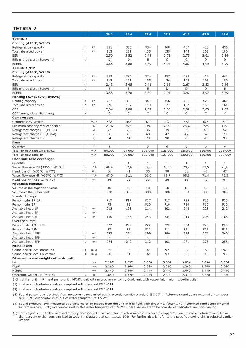
TETRIS 2 29.4 32.4 33.4 37.4 41.4 43.6 47.6TETRIS 2Cooling (A35°C; W7°C)Refrigeration capacity (1) kW 281 305 334 368 407 426 456Total absorbed power (1) kW 112 121 135 135 148 163 180EER (1) 2,50 2,52 2,48 2,73 2,75 2,61 2,54EER energy class (Eurovent) (1) D D E C C D DESEER 3,68 3,88 3,89 4,02 4,07 4,09 3,99TETRIS 2 /HPCooling (A35°C; W7°C)Refrigeration capacity (1) kW 272 296 324 357 395 413 443Total absorbed power (1) kW 112 121 135 134 148 163 180EER (1) 2,43 2,45 2,41 2,66 2,67 2,53 2,46EER energy class (Eurovent) (1) E E E D D D EESEER 3,58 3,78 3,80 3,91 3,97 3,97 3,89Heating (A7°C/87%; W45°C)Heating capacity (2) kW 282 308 341 356 401 423 461Total absorbed power (2) kW 99 107 119 127 137 150 161COP (2) 2,84 2,88 2,87 2,80 2,92 2,83 2,87COP energy class (Eurovent) (2) C C C C C C CCompressorsCompressors/Circuits n°/n° 4/2 4/2 4/2 4/2 4/2 6/2 6/2Minimum capacity reduction step % 23% 25% 23% 25% 25% 15% 17%Refrigerant charge CH (MCHX) kg 27 28 36 39 39 49 52Refrigerant charge CH (Cu/Al) kg 36 40 48 47 47 62 70Refrigerant charge HP kg 64 64 78 90 90 90 90FansQuantity n° 4 4 5 6 6 6 6Total air flow rate CH (MCHX) m3/h 84.000 84.000 105.000 126.000 126.000 126.000 126.000Total air flow rate HP m3/h 80.000 80.000 100.000 120.000 120.000 120.000 120.000User-side heat exchangerQuantity n° 1 1 1 1 1 1 1Water flow rate CH (A35°C; W7°C) (1) m3/h 48,4 52,6 57,6 63,6 70,2 73,5 78,8Head loss CH (A35°C; W7°C) (1) kPa 36 41 35 38 38 42 47Water flow rate HP (A35°C; W7°C) (1) m3/h 47,0 51,1 56,0 61,7 68,1 71,4 76,5Head loss HP (A35°C; W7°C) (1) kPa 34 39 33 36 36 40 44Hydraulic modulesVolume of the expansion vessel l 18 18 18 18 18 18 18Volume of the buffer tank l 300 300 300 300 300 300 300Standard pumpsPump model 1P, 2P P17 P17 P17 P17 P25 P25 P25Pump model 3P P3 P3 P10 P10 P10 P10 P10Available head 1P (1) kPa 212 193 214 203 248 228 212Available head 2P (1) kPa - - - - - - -Available head 3P (1) kPa 150 135 243 234 213 206 188Oversize pumpsPump model 1PM, 2PM P22 P22 P22 P22 P28 P28 P28Pump model 3PM P7 P7 P11 P11 P11 P11 P11Available head 1PM (1) kPa 287 274 299 290 276 274 260Available head 2PM (1) kPa - - - - - - -Available head 3PM (1) kPa 274 249 312 303 281 275 258Noise levelsSound power level basic unit (3) dB(A) 95 96 97 97 97 97 97Sound power level LN version (3) dB(A) 90 91 92 93 93 93 93Dimensions and weights of basic unitLength mm 2.297 2.297 3.834 3.834 3.834 3.834 3.834Depth mm 2.260 2.260 2.260 2.260 2.260 2.260 2.260Height mm 2.440 2.440 2.440 2.440 2.440 2.440 2.440Operating weight CH (MCHX) (5) kg 1.840 1.870 2.240 2.300 2.370 2.770 2.830( CH: chiller unit ; HP: heat pump unit ; MCHX: unit with microchannel coils ; CuAl: unit with copper/aluminium tube/fin coils )
(1) in attesa di traduzione Values compliant with standard EN 14511
(2) in attesa di traduzione Values compliant with standard EN 14511
(3) Sound power level obtained from measurements carried out in accordance with standard ISO 3744. Reference conditions: external air tempera-ture 35°C; evaporator inlet/outlet water temperature 12/7°C
(4) Sound pressure level measured at a distance of 10 metres from the unit in free field, with directivity factor Q=2. Reference conditions: external air temperature 35°C; evaporator inlet-outlet water temperature 12/7°C. These values are to be considered indicative and non-binding.
(5) The weight refers to the unit without any accessory. The introduction of a few accessories such as copper/aluminum coils, hydraulic modules or the recovery exchangers can lead to weight increased that can exceed 10%. For further details refer to the specific drawing of the selected config-uration.
24
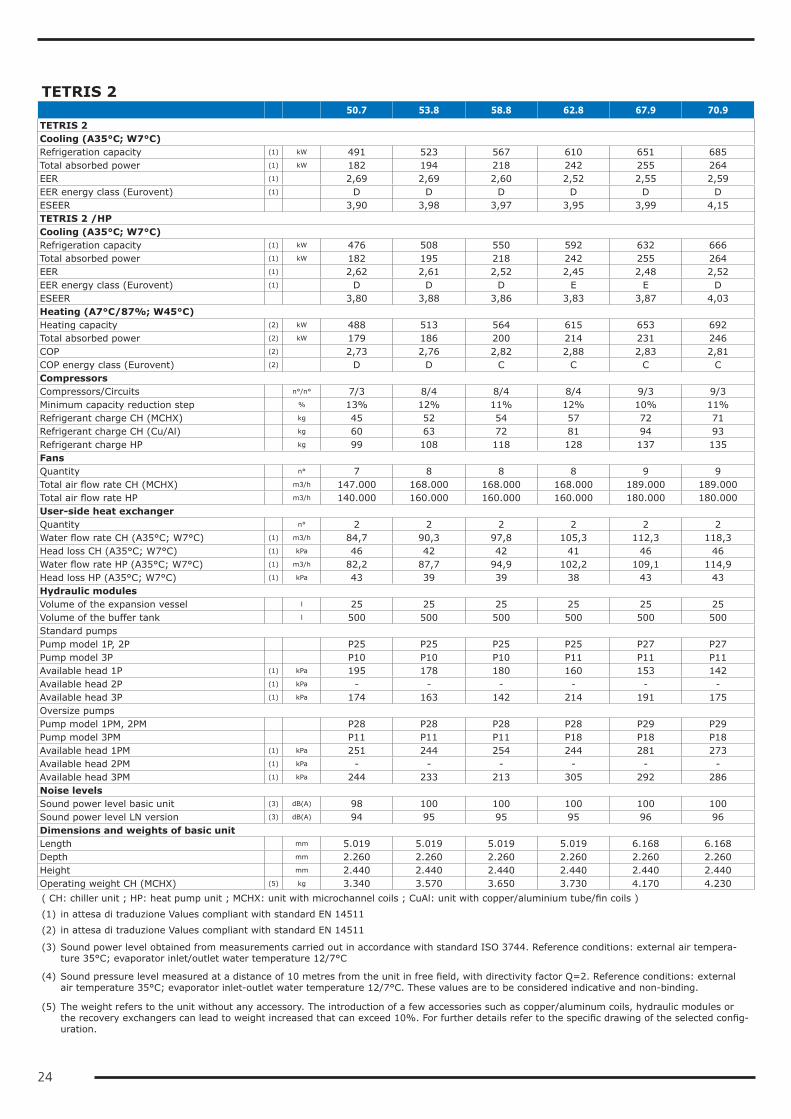
TETRIS 2 50.7 53.8 58.8 62.8 67.9 70.9TETRIS 2Cooling (A35°C; W7°C)Refrigeration capacity (1) kW 491 523 567 610 651 685Total absorbed power (1) kW 182 194 218 242 255 264EER (1) 2,69 2,69 2,60 2,52 2,55 2,59EER energy class (Eurovent) (1) D D D D D DESEER 3,90 3,98 3,97 3,95 3,99 4,15TETRIS 2 /HPCooling (A35°C; W7°C)Refrigeration capacity (1) kW 476 508 550 592 632 666Total absorbed power (1) kW 182 195 218 242 255 264EER (1) 2,62 2,61 2,52 2,45 2,48 2,52EER energy class (Eurovent) (1) D D D E E DESEER 3,80 3,88 3,86 3,83 3,87 4,03Heating (A7°C/87%; W45°C)Heating capacity (2) kW 488 513 564 615 653 692Total absorbed power (2) kW 179 186 200 214 231 246COP (2) 2,73 2,76 2,82 2,88 2,83 2,81COP energy class (Eurovent) (2) D D C C C CCompressorsCompressors/Circuits n°/n° 7/3 8/4 8/4 8/4 9/3 9/3Minimum capacity reduction step % 13% 12% 11% 12% 10% 11%Refrigerant charge CH (MCHX) kg 45 52 54 57 72 71Refrigerant charge CH (Cu/Al) kg 60 63 72 81 94 93Refrigerant charge HP kg 99 108 118 128 137 135FansQuantity n° 7 8 8 8 9 9Total air flow rate CH (MCHX) m3/h 147.000 168.000 168.000 168.000 189.000 189.000Total air flow rate HP m3/h 140.000 160.000 160.000 160.000 180.000 180.000User-side heat exchangerQuantity n° 2 2 2 2 2 2Water flow rate CH (A35°C; W7°C) (1) m3/h 84,7 90,3 97,8 105,3 112,3 118,3Head loss CH (A35°C; W7°C) (1) kPa 46 42 42 41 46 46Water flow rate HP (A35°C; W7°C) (1) m3/h 82,2 87,7 94,9 102,2 109,1 114,9Head loss HP (A35°C; W7°C) (1) kPa 43 39 39 38 43 43Hydraulic modulesVolume of the expansion vessel l 25 25 25 25 25 25Volume of the buffer tank l 500 500 500 500 500 500Standard pumpsPump model 1P, 2P P25 P25 P25 P25 P27 P27Pump model 3P P10 P10 P10 P11 P11 P11Available head 1P (1) kPa 195 178 180 160 153 142Available head 2P (1) kPa - - - - - -Available head 3P (1) kPa 174 163 142 214 191 175Oversize pumpsPump model 1PM, 2PM P28 P28 P28 P28 P29 P29Pump model 3PM P11 P11 P11 P18 P18 P18Available head 1PM (1) kPa 251 244 254 244 281 273Available head 2PM (1) kPa - - - - - -Available head 3PM (1) kPa 244 233 213 305 292 286Noise levelsSound power level basic unit (3) dB(A) 98 100 100 100 100 100Sound power level LN version (3) dB(A) 94 95 95 95 96 96Dimensions and weights of basic unitLength mm 5.019 5.019 5.019 5.019 6.168 6.168Depth mm 2.260 2.260 2.260 2.260 2.260 2.260Height mm 2.440 2.440 2.440 2.440 2.440 2.440Operating weight CH (MCHX) (5) kg 3.340 3.570 3.650 3.730 4.170 4.230( CH: chiller unit ; HP: heat pump unit ; MCHX: unit with microchannel coils ; CuAl: unit with copper/aluminium tube/fin coils )
(1) in attesa di traduzione Values compliant with standard EN 14511
(2) in attesa di traduzione Values compliant with standard EN 14511
(3) Sound power level obtained from measurements carried out in accordance with standard ISO 3744. Reference conditions: external air tempera-ture 35°C; evaporator inlet/outlet water temperature 12/7°C
(4) Sound pressure level measured at a distance of 10 metres from the unit in free field, with directivity factor Q=2. Reference conditions: external air temperature 35°C; evaporator inlet-outlet water temperature 12/7°C. These values are to be considered indicative and non-binding.
(5) The weight refers to the unit without any accessory. The introduction of a few accessories such as copper/aluminum coils, hydraulic modules or the recovery exchangers can lead to weight increased that can exceed 10%. For further details refer to the specific drawing of the selected config-uration.
25
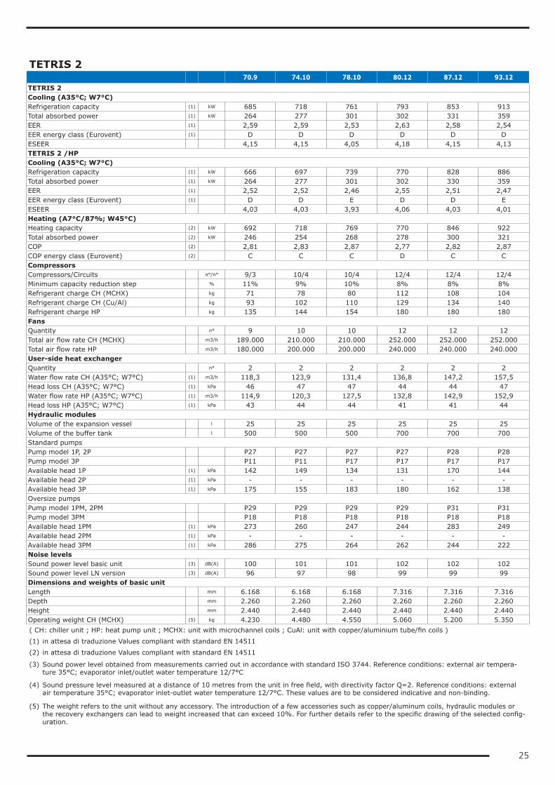
TETRIS 2 70.9 74.10 78.10 80.12 87.12 93.12TETRIS 2Cooling (A35°C; W7°C)Refrigeration capacity (1) kW 685 718 761 793 853 913Total absorbed power (1) kW 264 277 301 302 331 359EER (1) 2,59 2,59 2,53 2,63 2,58 2,54EER energy class (Eurovent) (1) D D D D D DESEER 4,15 4,15 4,05 4,18 4,15 4,13TETRIS 2 /HPCooling (A35°C; W7°C)Refrigeration capacity (1) kW 666 697 739 770 828 886Total absorbed power (1) kW 264 277 301 302 330 359EER (1) 2,52 2,52 2,46 2,55 2,51 2,47EER energy class (Eurovent) (1) D D E D D EESEER 4,03 4,03 3,93 4,06 4,03 4,01Heating (A7°C/87%; W45°C)Heating capacity (2) kW 692 718 769 770 846 922Total absorbed power (2) kW 246 254 268 278 300 321COP (2) 2,81 2,83 2,87 2,77 2,82 2,87COP energy class (Eurovent) (2) C C C D C CCompressorsCompressors/Circuits n°/n° 9/3 10/4 10/4 12/4 12/4 12/4Minimum capacity reduction step % 11% 9% 10% 8% 8% 8%Refrigerant charge CH (MCHX) kg 71 78 80 112 108 104Refrigerant charge CH (Cu/Al) kg 93 102 110 129 134 140Refrigerant charge HP kg 135 144 154 180 180 180FansQuantity n° 9 10 10 12 12 12Total air flow rate CH (MCHX) m3/h 189.000 210.000 210.000 252.000 252.000 252.000Total air flow rate HP m3/h 180.000 200.000 200.000 240.000 240.000 240.000User-side heat exchangerQuantity n° 2 2 2 2 2 2Water flow rate CH (A35°C; W7°C) (1) m3/h 118,3 123,9 131,4 136,8 147,2 157,5Head loss CH (A35°C; W7°C) (1) kPa 46 47 47 44 44 47Water flow rate HP (A35°C; W7°C) (1) m3/h 114,9 120,3 127,5 132,8 142,9 152,9Head loss HP (A35°C; W7°C) (1) kPa 43 44 44 41 41 44Hydraulic modulesVolume of the expansion vessel l 25 25 25 25 25 25Volume of the buffer tank l 500 500 500 700 700 700Standard pumpsPump model 1P, 2P P27 P27 P27 P27 P28 P28Pump model 3P P11 P11 P17 P17 P17 P17Available head 1P (1) kPa 142 149 134 131 170 144Available head 2P (1) kPa - - - - - -Available head 3P (1) kPa 175 155 183 180 162 138Oversize pumpsPump model 1PM, 2PM P29 P29 P29 P29 P31 P31Pump model 3PM P18 P18 P18 P18 P18 P18Available head 1PM (1) kPa 273 260 247 244 283 249Available head 2PM (1) kPa - - - - - -Available head 3PM (1) kPa 286 275 264 262 244 222Noise levelsSound power level basic unit (3) dB(A) 100 101 101 102 102 102Sound power level LN version (3) dB(A) 96 97 98 99 99 99Dimensions and weights of basic unitLength mm 6.168 6.168 6.168 7.316 7.316 7.316Depth mm 2.260 2.260 2.260 2.260 2.260 2.260Height mm 2.440 2.440 2.440 2.440 2.440 2.440Operating weight CH (MCHX) (5) kg 4.230 4.480 4.550 5.060 5.200 5.350( CH: chiller unit ; HP: heat pump unit ; MCHX: unit with microchannel coils ; CuAl: unit with copper/aluminium tube/fin coils )
(1) in attesa di traduzione Values compliant with standard EN 14511
(2) in attesa di traduzione Values compliant with standard EN 14511
(3) Sound power level obtained from measurements carried out in accordance with standard ISO 3744. Reference conditions: external air tempera-ture 35°C; evaporator inlet/outlet water temperature 12/7°C
(4) Sound pressure level measured at a distance of 10 metres from the unit in free field, with directivity factor Q=2. Reference conditions: external air temperature 35°C; evaporator inlet-outlet water temperature 12/7°C. These values are to be considered indicative and non-binding.
(5) The weight refers to the unit without any accessory. The introduction of a few accessories such as copper/aluminum coils, hydraulic modules or the recovery exchangers can lead to weight increased that can exceed 10%. For further details refer to the specific drawing of the selected config-uration.
26
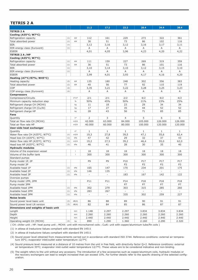
TETRIS 2 A 11.2 17.2 23.2 28.4 34.4 38.4TETRIS 2 ACooling (A35°C; W7°C)Refrigeration capacity (1) kW 112 161 229 273 322 361Total absorbed power (1) kW 36 51 73 86 102 116EER (1) 3,12 3,16 3,12 3,16 3,17 3,11EER energy class (Eurovent) (1) A A A A A AESEER 4,01 4,05 3,96 4,23 4,20 4,22TETRIS 2 A /HPCooling (A35°C; W7°C)Refrigeration capacity (1) kW 111 159 227 269 319 359Total absorbed power (1) kW 36 51 73 86 101 116EER (1) 3,10 3,14 3,10 3,12 3,15 3,10EER energy class (Eurovent) (1) A A A A A AESEER 3,99 4,01 3,93 4,17 4,16 4,20Heating (A7°C/87%; W45°C)Heating capacity (2) kW 135 180 248 302 356 383Total absorbed power (2) kW 40 56 77 92 110 119COP (2) 3,35 3,21 3,22 3,28 3,25 3,23COP energy class (Eurovent) (2) A A A A A ACompressorsCompressors/Circuits n°/n° 2/1 2/1 2/2 4/2 4/2 4/2Minimum capacity reduction step % 50% 45% 50% 21% 23% 25%Refrigerant charge CH (MCHX) kg 11 18 23 29 34 34Refrigerant charge CH (Cu/Al) kg 17 27 35 44 52 52Refrigerant charge HP kg 28 43 56 71 85 85FansQuantity n° 2 3 4 5 6 6Total air flow rate CH (MCHX) m3/h 42.000 63.000 84.000 105.000 126.000 126.000Total air flow rate HP m3/h 40.000 60.000 80.000 100.000 120.000 120.000User-side heat exchangerQuantity n° 1 1 1 1 1 1Water flow rate CH (A35°C; W7°C) (1) m3/h 19,3 27,8 39,5 47,1 55,6 62,4Head loss CH (A35°C; W7°C) (1) kPa 47 42 29 32 37 43Water flow rate HP (A35°C; W7°C) (1) m3/h 19,2 27,5 39,2 46,4 55,0 62,0Head loss HP (A35°C; W7°C) (1) kPa 46 41 28 30 35 40Hydraulic modulesVolume of the expansion vessel l 18 18 18 18 18 18Volume of the buffer tank l 300 300 300 300 300 300Standard pumpsPump model 1P, 2P P9 P9 P10 P17 P17 P17Pump model 3P - - P3 P3 P3 P3Available head 1P (1) kPa 165 147 170 234 201 175Available head 2P (1) kPa 146 135 - - - -Available head 3P (1) kPa - - 183 167 142 122Oversize pumpsPump model 1PM, 2PM P11 P11 P14 P18 P18 P18Pump model 3PM - - P7 P7 P7 P7Available head 1PM (1) kPa 302 279 303 315 285 260Available head 2PM (1) kPa 283 267 - - - -Available head 3PM (1) kPa - - 335 302 259 227Noise levelsSound power level basic unit (3) dB(A) 86 88 89 90 91 91Sound power level LN version (3) dB(A) 82 84 85 86 87 87Dimensions and weights of basic unitLength mm 1.148 2.297 2.297 3.834 3.834 3.834Depth mm 2.260 2.260 2.260 2.260 2.260 2.260Height mm 2.440 2.440 2.440 2.440 2.440 2.440Operating weight CH (MCHX) (5) kg 890 1.290 1.360 2.160 2.290 2.320( CH: chiller unit ; HP: heat pump unit ; MCHX: unit with microchannel coils ; CuAl: unit with copper/aluminium tube/fin coils )
(1) in attesa di traduzione Values compliant with standard EN 14511
(2) in attesa di traduzione Values compliant with standard EN 14511
(3) Sound power level obtained from measurements carried out in accordance with standard ISO 3744. Reference conditions: external air tempera-ture 35°C; evaporator inlet/outlet water temperature 12/7°C
(4) Sound pressure level measured at a distance of 10 metres from the unit in free field, with directivity factor Q=2. Reference conditions: external air temperature 35°C; evaporator inlet-outlet water temperature 12/7°C. These values are to be considered indicative and non-binding.
(5) The weight refers to the unit without any accessory. The introduction of a few accessories such as copper/aluminum coils, hydraulic modules or the recovery exchangers can lead to weight increased that can exceed 10%. For further details refer to the specific drawing of the selected config-uration.
27
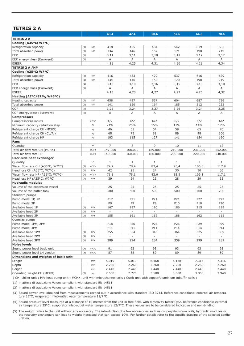
TETRIS 2 A 43.4 47.4 50.6 57.6 64.6 70.6TETRIS 2 ACooling (A35°C; W7°C)Refrigeration capacity (1) kW 418 455 484 542 619 683Total absorbed power (1) kW 134 146 152 171 198 219EER (1) 3,11 3,11 3,18 3,17 3,12 3,12EER energy class (Eurovent) (1) A A A A A AESEER 4,18 4,25 4,31 4,30 4,28 4,34TETRIS 2 A /HPCooling (A35°C; W7°C)Refrigeration capacity (1) kW 416 453 479 537 616 679Total absorbed power (1) kW 134 146 152 170 198 219EER (1) 3,10 3,10 3,16 3,15 3,10 3,10EER energy class (Eurovent) (1) A A A A A AESEER 4,15 4,23 4,27 4,27 4,26 4,32Heating (A7°C/87%; W45°C)Heating capacity (2) kW 458 487 537 604 687 756Total absorbed power (2) kW 141 150 164 185 212 232COP (2) 3,25 3,24 3,27 3,26 3,24 3,25COP energy class (Eurovent) (2) A A A A A ACompressorsCompressors/Circuits n°/n° 4/2 4/2 6/2 6/2 6/2 6/2Minimum capacity reduction step % 21% 25% 15% 17% 14% 17%Refrigerant charge CH (MCHX) kg 46 51 54 59 65 70Refrigerant charge CH (Cu/Al) kg 68 75 81 89 98 106Refrigerant charge HP kg 103 115 127 141 154 160FansQuantity n° 7 8 9 10 11 12Total air flow rate CH (MCHX) m3/h 147.000 168.000 189.000 210.000 231.000 252.000Total air flow rate HP m3/h 140.000 160.000 180.000 200.000 220.000 240.000User-side heat exchangerQuantity n° 1 1 1 1 1 1Water flow rate CH (A35°C; W7°C) (1) m3/h 72,2 78,4 83,4 93,4 106,8 117,9Head loss CH (A35°C; W7°C) (1) kPa 42 25 24 30 30 36Water flow rate HP (A35°C; W7°C) (1) m3/h 71,8 78,1 82,6 92,5 106,1 117,1Head loss HP (A35°C; W7°C) (1) kPa 39 24 23 28 29 35Hydraulic modulesVolume of the expansion vessel l 25 25 25 25 25 25Volume of the buffer tank l 500 500 500 500 700 700Standard pumpsPump model 1P, 2P P17 P21 P21 P21 P27 P27Pump model 3P P9 P9 P9 P10 P10 P10Available head 1P (1) kPa 167 197 190 186 215 199Available head 2P (1) kPa - - - - - -Available head 3P (1) kPa 155 161 152 188 162 155Oversize pumpsPump model 1PM, 2PM P18 P26 P26 P26 P29 P29Pump model 3PM P11 P11 P11 P14 P14 P14Available head 1PM (1) kPa 255 354 346 364 325 309Available head 2PM (1) kPa - - - - - -Available head 3PM (1) kPa 289 294 284 359 299 289Noise levelsSound power level basic unit (3) dB(A) 91 92 93 93 93 93Sound power level LN version (3) dB(A) 87 88 89 89 89 89Dimensions and weights of basic unitLength mm 5.019 5.019 6.168 6.168 7.316 7.316Depth mm 2.260 2.260 2.260 2.260 2.260 2.260Height mm 2.440 2.440 2.440 2.440 2.440 2.440Operating weight CH (MCHX) (5) kg 2.650 2.770 3.500 3.580 3.850 3.940( CH: chiller unit ; HP: heat pump unit ; MCHX: unit with microchannel coils ; CuAl: unit with copper/aluminium tube/fin coils )
(1) in attesa di traduzione Values compliant with standard EN 14511
(2) in attesa di traduzione Values compliant with standard EN 14511
(3) Sound power level obtained from measurements carried out in accordance with standard ISO 3744. Reference conditions: external air tempera-ture 35°C; evaporator inlet/outlet water temperature 12/7°C
(4) Sound pressure level measured at a distance of 10 metres from the unit in free field, with directivity factor Q=2. Reference conditions: external air temperature 35°C; evaporator inlet-outlet water temperature 12/7°C. These values are to be considered indicative and non-binding.
(5) The weight refers to the unit without any accessory. The introduction of a few accessories such as copper/aluminum coils, hydraulic modules or the recovery exchangers can lead to weight increased that can exceed 10%. For further details refer to the specific drawing of the selected config-uration.
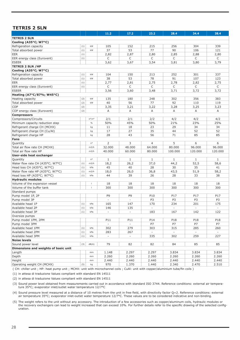
28
TETRIS 2 SLN 11.2 17.2 23.2 28.4 34.4 38.4TETRIS 2 SLNCooling (A35°C; W7°C)Refrigeration capacity (1) kW 105 152 215 256 304 339Total absorbed power (1) kW 37 53 77 90 106 121EER (1) 2,82 2,87 2,80 2,85 2,88 2,80EER energy class (Eurovent) (1) C C C C C CESEER 3,62 3,67 3,54 3,81 3,80 3,79TETRIS 2 SLN /HPCooling (A35°C; W7°C)Refrigeration capacity (1) kW 104 150 213 252 301 337Total absorbed power (1) kW 38 53 78 91 107 123EER (1) 2,77 2,81 2,75 2,78 2,82 2,75EER energy class (Eurovent) (1) C C C C C CESEER 3,56 3,60 3,48 3,71 3,72 3,72Heating (A7°C/87%; W45°C)Heating capacity (2) kW 135 180 248 302 356 383Total absorbed power (2) kW 40 56 77 92 110 119COP (2) 3,35 3,21 3,22 3,28 3,25 3,23COP energy class (Eurovent) (2) A A A A A ACompressorsCompressors/Circuits n°/n° 2/1 2/1 2/2 4/2 4/2 4/2Minimum capacity reduction step % 50% 45% 50% 21% 23% 25%Refrigerant charge CH (MCHX) kg 11 18 23 29 34 34Refrigerant charge CH (Cu/Al) kg 17 27 35 44 52 52Refrigerant charge HP kg 28 43 56 71 85 85FansQuantity n° 2 3 4 5 6 6Total air flow rate CH (MCHX) m3/h 32.000 48.000 64.000 80.000 96.000 96.000Total air flow rate HP m3/h 40.000 60.000 80.000 100.000 120.000 120.000User-side heat exchangerQuantity n° 1 1 1 1 1 1Water flow rate CH (A35°C; W7°C) (1) m3/h 18,2 26,2 37,0 44,2 52,5 58,6Head loss CH (A35°C; W7°C) (1) kPa 45 40 28 30 35 41Water flow rate HP (A35°C; W7°C) (1) m3/h 18,0 26,0 36,8 43,5 51,9 58,2Head loss HP (A35°C; W7°C) (1) kPa 44 39 26 28 33 38Hydraulic modulesVolume of the expansion vessel l 18 18 18 18 18 18Volume of the buffer tank l 300 300 300 300 300 300Standard pumpsPump model 1P, 2P P9 P9 P10 P17 P17 P17Pump model 3P - - P3 P3 P3 P3Available head 1P (1) kPa 165 147 170 234 201 175Available head 2P (1) kPa 146 135 - - - -Available head 3P (1) kPa - - 183 167 142 122Oversize pumpsPump model 1PM, 2PM P11 P11 P14 P18 P18 P18Pump model 3PM - - P7 P7 P7 P7Available head 1PM (1) kPa 302 279 303 315 285 260Available head 2PM (1) kPa 283 267 - - - -Available head 3PM (1) kPa - - 335 302 259 227Noise levelsSound power level (3) dB(A) 79 82 82 84 85 85Dimensions and weights of basic unitLength mm 1.148 2.297 2.297 3.834 3.834 3.834Depth mm 2.260 2.260 2.260 2.260 2.260 2.260Height mm 2.440 2.440 2.440 2.440 2.440 2.440Operating weight CH (MCHX) (5) kg 970 1.370 1.440 2.340 2.470 2.510( CH: chiller unit ; HP: heat pump unit ; MCHX: unit with microchannel coils ; CuAl: unit with copper/aluminium tube/fin coils )
(1) in attesa di traduzione Values compliant with standard EN 14511
(2) in attesa di traduzione Values compliant with standard EN 14511
(3) Sound power level obtained from measurements carried out in accordance with standard ISO 3744. Reference conditions: external air tempera-ture 35°C; evaporator inlet/outlet water temperature 12/7°C
(4) Sound pressure level measured at a distance of 10 metres from the unit in free field, with directivity factor Q=2. Reference conditions: external air temperature 35°C; evaporator inlet-outlet water temperature 12/7°C. These values are to be considered indicative and non-binding.
(5) The weight refers to the unit without any accessory. The introduction of a few accessories such as copper/aluminum coils, hydraulic modules or the recovery exchangers can lead to weight increased that can exceed 10%. For further details refer to the specific drawing of the selected config-uration.

29
TETRIS 2 SLN 43.4 47.4 50.6 57.6 64.6 70.6TETRIS 2 SLNCooling (A35°C; W7°C)Refrigeration capacity (1) kW 392 426 456 510 582 642Total absorbed power (1) kW 141 153 158 178 208 229EER (1) 2,78 2,79 2,88 2,87 2,80 2,81EER energy class (Eurovent) (1) C C C C C CESEER 3,73 3,80 3,90 3,89 3,84 3,90TETRIS 2 SLN /HPCooling (A35°C; W7°C)Refrigeration capacity (1) kW 390 425 451 505 578 638Total absorbed power (1) kW 143 155 160 180 210 232EER (1) 2,73 2,74 2,82 2,81 2,75 2,75EER energy class (Eurovent) (1) C C C C C CESEER 3,66 3,74 3,82 3,81 3,76 3,82Heating (A7°C/87%; W45°C)Heating capacity (2) kW 458 487 537 604 687 756Total absorbed power (2) kW 141 150 164 185 212 232COP (2) 3,25 3,24 3,27 3,26 3,24 3,25COP energy class (Eurovent) (2) A A A A A ACompressorsCompressors/Circuits n°/n° 4/2 4/2 6/2 6/2 6/2 6/2Minimum capacity reduction step % 21% 25% 15% 17% 14% 17%Refrigerant charge CH (MCHX) kg 46 51 54 59 65 70Refrigerant charge CH (Cu/Al) kg 68 75 81 89 98 106Refrigerant charge HP kg 103 115 127 141 154 160FansQuantity n° 7 8 9 10 11 12Total air flow rate CH (MCHX) m3/h 112.000 128.000 144.000 160.000 176.000 192.000Total air flow rate HP m3/h 140.000 160.000 180.000 200.000 220.000 240.000User-side heat exchangerQuantity n° 1 1 1 1 1 1Water flow rate CH (A35°C; W7°C) (1) m3/h 67,6 73,5 78,6 87,9 100,3 110,7Head loss CH (A35°C; W7°C) (1) kPa 39 23 23 28 29 34Water flow rate HP (A35°C; W7°C) (1) m3/h 67,3 73,2 77,8 87,1 99,7 110,0Head loss HP (A35°C; W7°C) (1) kPa 37 22 22 26 28 33Hydraulic modulesVolume of the expansion vessel l 25 25 25 25 25 25Volume of the buffer tank l 500 500 500 500 700 700Standard pumpsPump model 1P, 2P P17 P21 P21 P21 P27 P27Pump model 3P P9 P9 P9 P10 P10 P10Available head 1P (1) kPa 167 197 190 186 215 199Available head 2P (1) kPa - - - - - -Available head 3P (1) kPa 155 161 152 188 162 155Oversize pumpsPump model 1PM, 2PM P18 P26 P26 P26 P29 P29Pump model 3PM P11 P11 P11 P14 P14 P14Available head 1PM (1) kPa 255 354 346 364 325 309Available head 2PM (1) kPa - - - - - -Available head 3PM (1) kPa 289 294 284 359 299 289Noise levelsSound power level (3) dB(A) 85 85 87 87 87 87Dimensions and weights of basic unitLength mm 5.019 5.019 6.168 6.168 7.316 7.316Depth mm 2.260 2.260 2.260 2.260 2.260 2.260Height mm 2.440 2.440 2.440 2.440 2.440 2.440Operating weight CH (MCHX) (5) kg 2.820 2.940 3.770 3.860 4.090 4.170( CH: chiller unit ; HP: heat pump unit ; MCHX: unit with microchannel coils ; CuAl: unit with copper/aluminium tube/fin coils )
(1) in attesa di traduzione Values compliant with standard EN 14511
(2) in attesa di traduzione Values compliant with standard EN 14511
(3) Sound power level obtained from measurements carried out in accordance with standard ISO 3744. Reference conditions: external air tempera-ture 35°C; evaporator inlet/outlet water temperature 12/7°C
(4) Sound pressure level measured at a distance of 10 metres from the unit in free field, with directivity factor Q=2. Reference conditions: external air temperature 35°C; evaporator inlet-outlet water temperature 12/7°C. These values are to be considered indicative and non-binding.
(5) The weight refers to the unit without any accessory. The introduction of a few accessories such as copper/aluminum coils, hydraulic modules or the recovery exchangers can lead to weight increased that can exceed 10%. For further details refer to the specific drawing of the selected config-uration.
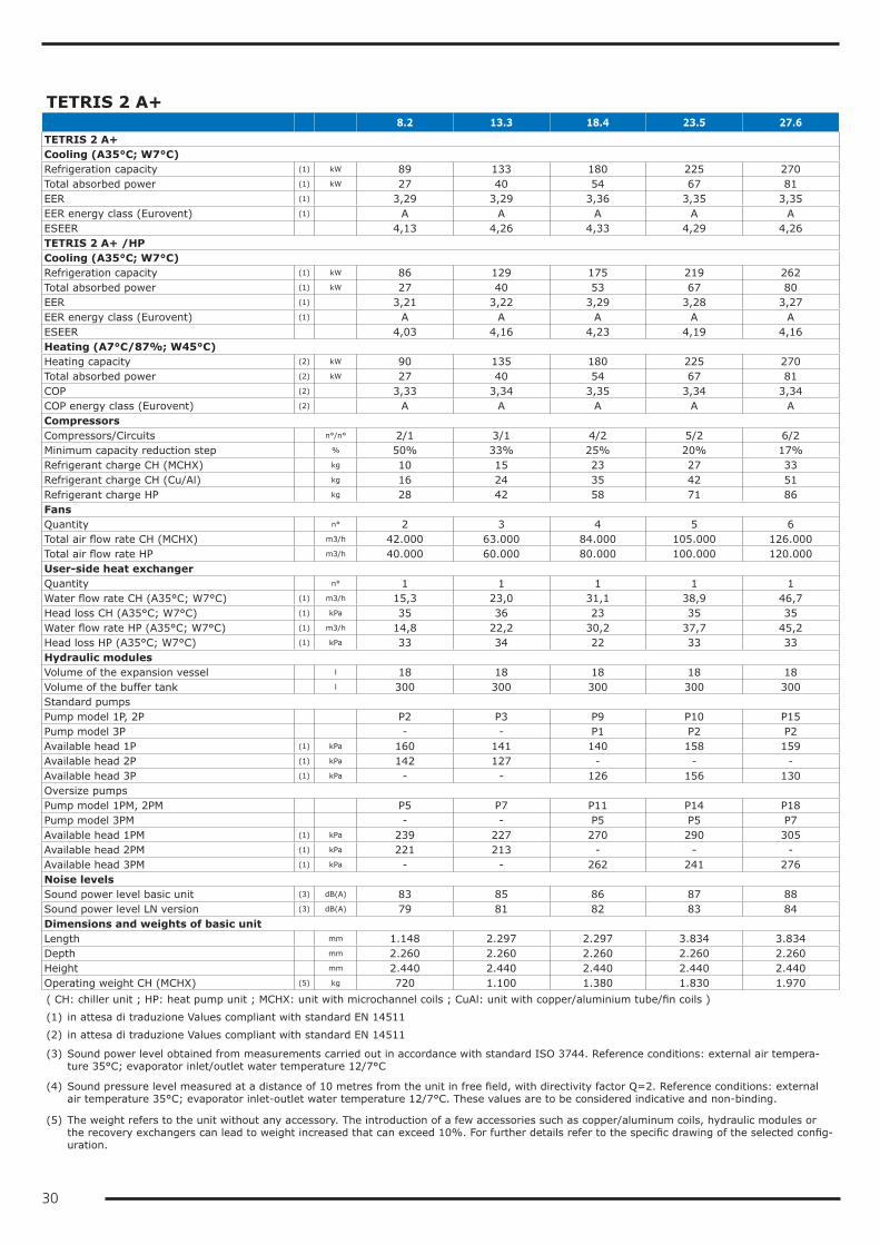
30
TETRIS 2 A+ 8.2 13.3 18.4 23.5 27.6TETRIS 2 A+Cooling (A35°C; W7°C)Refrigeration capacity (1) kW 89 133 180 225 270Total absorbed power (1) kW 27 40 54 67 81EER (1) 3,29 3,29 3,36 3,35 3,35EER energy class (Eurovent) (1) A A A A AESEER 4,13 4,26 4,33 4,29 4,26TETRIS 2 A+ /HPCooling (A35°C; W7°C)Refrigeration capacity (1) kW 86 129 175 219 262Total absorbed power (1) kW 27 40 53 67 80EER (1) 3,21 3,22 3,29 3,28 3,27EER energy class (Eurovent) (1) A A A A AESEER 4,03 4,16 4,23 4,19 4,16Heating (A7°C/87%; W45°C)Heating capacity (2) kW 90 135 180 225 270Total absorbed power (2) kW 27 40 54 67 81COP (2) 3,33 3,34 3,35 3,34 3,34COP energy class (Eurovent) (2) A A A A ACompressorsCompressors/Circuits n°/n° 2/1 3/1 4/2 5/2 6/2Minimum capacity reduction step % 50% 33% 25% 20% 17%Refrigerant charge CH (MCHX) kg 10 15 23 27 33Refrigerant charge CH (Cu/Al) kg 16 24 35 42 51Refrigerant charge HP kg 28 42 58 71 86FansQuantity n° 2 3 4 5 6Total air flow rate CH (MCHX) m3/h 42.000 63.000 84.000 105.000 126.000Total air flow rate HP m3/h 40.000 60.000 80.000 100.000 120.000User-side heat exchangerQuantity n° 1 1 1 1 1Water flow rate CH (A35°C; W7°C) (1) m3/h 15,3 23,0 31,1 38,9 46,7Head loss CH (A35°C; W7°C) (1) kPa 35 36 23 35 35Water flow rate HP (A35°C; W7°C) (1) m3/h 14,8 22,2 30,2 37,7 45,2Head loss HP (A35°C; W7°C) (1) kPa 33 34 22 33 33Hydraulic modulesVolume of the expansion vessel l 18 18 18 18 18Volume of the buffer tank l 300 300 300 300 300Standard pumpsPump model 1P, 2P P2 P3 P9 P10 P15Pump model 3P - - P1 P2 P2Available head 1P (1) kPa 160 141 140 158 159Available head 2P (1) kPa 142 127 - - -Available head 3P (1) kPa - - 126 156 130Oversize pumpsPump model 1PM, 2PM P5 P7 P11 P14 P18Pump model 3PM - - P5 P5 P7Available head 1PM (1) kPa 239 227 270 290 305Available head 2PM (1) kPa 221 213 - - -Available head 3PM (1) kPa - - 262 241 276Noise levelsSound power level basic unit (3) dB(A) 83 85 86 87 88Sound power level LN version (3) dB(A) 79 81 82 83 84Dimensions and weights of basic unitLength mm 1.148 2.297 2.297 3.834 3.834Depth mm 2.260 2.260 2.260 2.260 2.260Height mm 2.440 2.440 2.440 2.440 2.440Operating weight CH (MCHX) (5) kg 720 1.100 1.380 1.830 1.970( CH: chiller unit ; HP: heat pump unit ; MCHX: unit with microchannel coils ; CuAl: unit with copper/aluminium tube/fin coils )
(1) in attesa di traduzione Values compliant with standard EN 14511
(2) in attesa di traduzione Values compliant with standard EN 14511
(3) Sound power level obtained from measurements carried out in accordance with standard ISO 3744. Reference conditions: external air tempera-ture 35°C; evaporator inlet/outlet water temperature 12/7°C
(4) Sound pressure level measured at a distance of 10 metres from the unit in free field, with directivity factor Q=2. Reference conditions: external air temperature 35°C; evaporator inlet-outlet water temperature 12/7°C. These values are to be considered indicative and non-binding.
(5) The weight refers to the unit without any accessory. The introduction of a few accessories such as copper/aluminum coils, hydraulic modules or the recovery exchangers can lead to weight increased that can exceed 10%. For further details refer to the specific drawing of the selected config-uration.
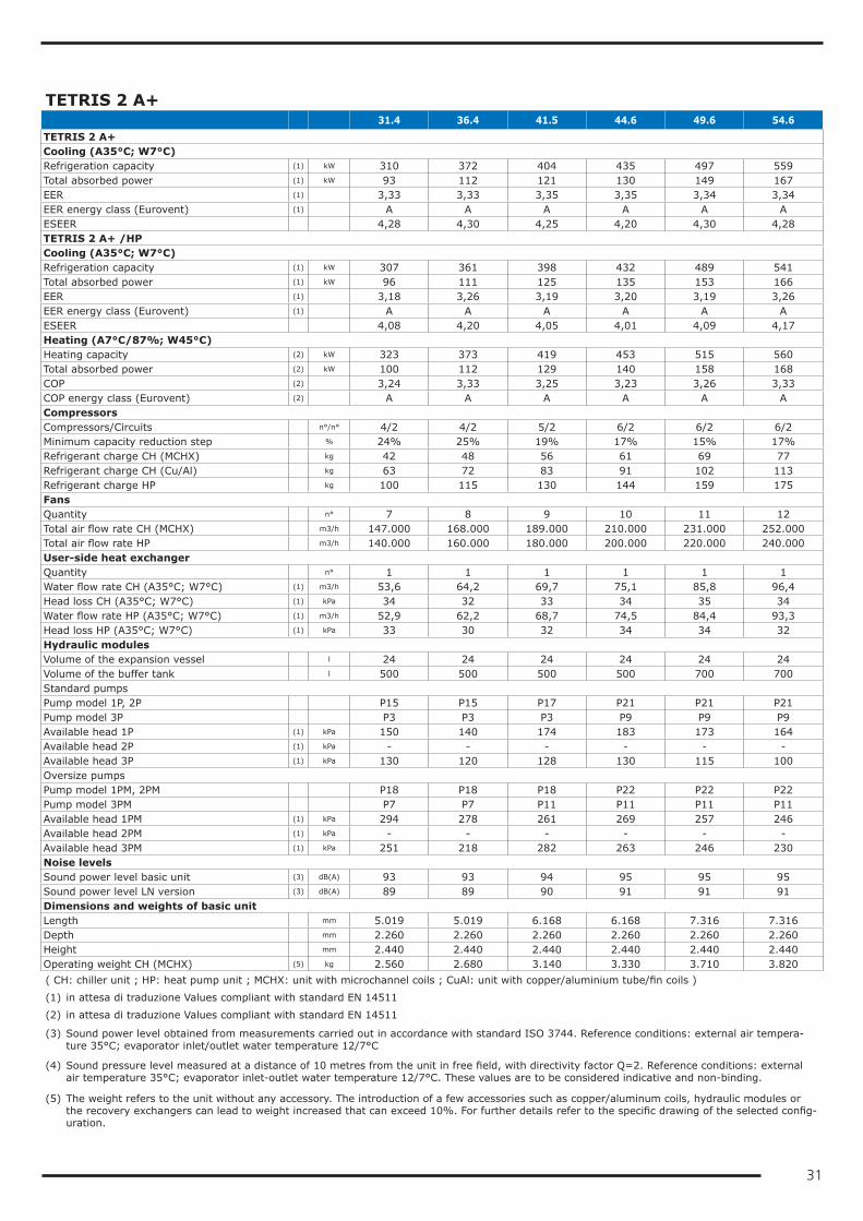
31
TETRIS 2 A+ 31.4 36.4 41.5 44.6 49.6 54.6TETRIS 2 A+Cooling (A35°C; W7°C)Refrigeration capacity (1) kW 310 372 404 435 497 559Total absorbed power (1) kW 93 112 121 130 149 167EER (1) 3,33 3,33 3,35 3,35 3,34 3,34EER energy class (Eurovent) (1) A A A A A AESEER 4,28 4,30 4,25 4,20 4,30 4,28TETRIS 2 A+ /HPCooling (A35°C; W7°C)Refrigeration capacity (1) kW 307 361 398 432 489 541Total absorbed power (1) kW 96 111 125 135 153 166EER (1) 3,18 3,26 3,19 3,20 3,19 3,26EER energy class (Eurovent) (1) A A A A A AESEER 4,08 4,20 4,05 4,01 4,09 4,17Heating (A7°C/87%; W45°C)Heating capacity (2) kW 323 373 419 453 515 560Total absorbed power (2) kW 100 112 129 140 158 168COP (2) 3,24 3,33 3,25 3,23 3,26 3,33COP energy class (Eurovent) (2) A A A A A ACompressorsCompressors/Circuits n°/n° 4/2 4/2 5/2 6/2 6/2 6/2Minimum capacity reduction step % 24% 25% 19% 17% 15% 17%Refrigerant charge CH (MCHX) kg 42 48 56 61 69 77Refrigerant charge CH (Cu/Al) kg 63 72 83 91 102 113Refrigerant charge HP kg 100 115 130 144 159 175FansQuantity n° 7 8 9 10 11 12Total air flow rate CH (MCHX) m3/h 147.000 168.000 189.000 210.000 231.000 252.000Total air flow rate HP m3/h 140.000 160.000 180.000 200.000 220.000 240.000User-side heat exchangerQuantity n° 1 1 1 1 1 1Water flow rate CH (A35°C; W7°C) (1) m3/h 53,6 64,2 69,7 75,1 85,8 96,4Head loss CH (A35°C; W7°C) (1) kPa 34 32 33 34 35 34Water flow rate HP (A35°C; W7°C) (1) m3/h 52,9 62,2 68,7 74,5 84,4 93,3Head loss HP (A35°C; W7°C) (1) kPa 33 30 32 34 34 32Hydraulic modulesVolume of the expansion vessel l 24 24 24 24 24 24Volume of the buffer tank l 500 500 500 500 700 700Standard pumpsPump model 1P, 2P P15 P15 P17 P21 P21 P21Pump model 3P P3 P3 P3 P9 P9 P9Available head 1P (1) kPa 150 140 174 183 173 164Available head 2P (1) kPa - - - - - -Available head 3P (1) kPa 130 120 128 130 115 100Oversize pumpsPump model 1PM, 2PM P18 P18 P18 P22 P22 P22Pump model 3PM P7 P7 P11 P11 P11 P11Available head 1PM (1) kPa 294 278 261 269 257 246Available head 2PM (1) kPa - - - - - -Available head 3PM (1) kPa 251 218 282 263 246 230Noise levelsSound power level basic unit (3) dB(A) 93 93 94 95 95 95Sound power level LN version (3) dB(A) 89 89 90 91 91 91Dimensions and weights of basic unitLength mm 5.019 5.019 6.168 6.168 7.316 7.316Depth mm 2.260 2.260 2.260 2.260 2.260 2.260Height mm 2.440 2.440 2.440 2.440 2.440 2.440Operating weight CH (MCHX) (5) kg 2.560 2.680 3.140 3.330 3.710 3.820( CH: chiller unit ; HP: heat pump unit ; MCHX: unit with microchannel coils ; CuAl: unit with copper/aluminium tube/fin coils )
(1) in attesa di traduzione Values compliant with standard EN 14511
(2) in attesa di traduzione Values compliant with standard EN 14511
(3) Sound power level obtained from measurements carried out in accordance with standard ISO 3744. Reference conditions: external air tempera-ture 35°C; evaporator inlet/outlet water temperature 12/7°C
(4) Sound pressure level measured at a distance of 10 metres from the unit in free field, with directivity factor Q=2. Reference conditions: external air temperature 35°C; evaporator inlet-outlet water temperature 12/7°C. These values are to be considered indicative and non-binding.
(5) The weight refers to the unit without any accessory. The introduction of a few accessories such as copper/aluminum coils, hydraulic modules or the recovery exchangers can lead to weight increased that can exceed 10%. For further details refer to the specific drawing of the selected config-uration.
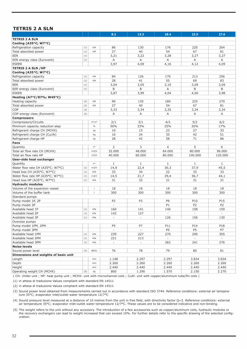
32
TETRIS 2 A SLN 8.2 13.3 18.4 23.5 27.6TETRIS 2 A SLNCooling (A35°C; W7°C)Refrigeration capacity (1) kW 86 130 176 220 264Total absorbed power (1) kW 27 40 54 67 81EER (1) 3,21 3,22 3,28 3,27 3,27EER energy class (Eurovent) (1) A A A A AESEER 3,97 4,09 4,16 4,12 4,09TETRIS 2 A SLN /HPCooling (A35°C; W7°C)Refrigeration capacity (1) kW 84 126 170 213 256Total absorbed power (1) kW 28 41 55 69 83EER (1) 3,04 3,05 3,10 3,09 3,09EER energy class (Eurovent) (1) B B A B BESEER 3,87 3,99 4,04 4,00 3,98Heating (A7°C/87%; W45°C)Heating capacity (2) kW 90 135 180 225 270Total absorbed power (2) kW 27 40 54 67 81COP (2) 3,33 3,34 3,35 3,34 3,34COP energy class (Eurovent) (2) A A A A ACompressorsCompressors/Circuits n°/n° 2/1 3/1 4/2 5/2 6/2Minimum capacity reduction step % 50% 33% 25% 20% 17%Refrigerant charge CH (MCHX) kg 10 15 23 27 33Refrigerant charge CH (Cu/Al) kg 16 24 35 42 51Refrigerant charge HP kg 28 42 58 71 86FansQuantity n° 2 3 4 5 6Total air flow rate CH (MCHX) m3/h 32.000 48.000 64.000 80.000 96.000Total air flow rate HP m3/h 40.000 60.000 80.000 100.000 120.000User-side heat exchangerQuantity n° 1 1 1 1 1Water flow rate CH (A35°C; W7°C) (1) m3/h 14,9 22,4 30,3 37,9 45,5Head loss CH (A35°C; W7°C) (1) kPa 33 34 22 33 33Water flow rate HP (A35°C; W7°C) (1) m3/h 14,5 21,7 29,4 36,7 44,1Head loss HP (A35°C; W7°C) (1) kPa 31 32 21 31 31Hydraulic modulesVolume of the expansion vessel l 18 18 18 18 18Volume of the buffer tank l 300 300 300 300 300Standard pumpsPump model 1P, 2P P2 P3 P9 P10 P15Pump model 3P - - P1 P2 P2Available head 1P (1) kPa 160 141 140 158 159Available head 2P (1) kPa 142 127 - - -Available head 3P (1) kPa - - 126 156 130Oversize pumpsPump model 1PM, 2PM P5 P7 P11 P14 P18Pump model 3PM - - P5 P5 P7Available head 1PM (1) kPa 239 227 270 290 305Available head 2PM (1) kPa 221 213 - - -Available head 3PM (1) kPa - - 262 241 276Noise levelsSound power level (3) dB(A) 76 78 79 80 81Dimensions and weights of basic unitLength mm 1.148 2.297 2.297 3.834 3.834Depth mm 2.260 2.260 2.260 2.260 2.260Height mm 2.440 2.440 2.440 2.440 2.440Operating weight CH (MCHX) (5) kg 800 1.290 1.570 2.150 2.270( CH: chiller unit ; HP: heat pump unit ; MCHX: unit with microchannel coils ; CuAl: unit with copper/aluminium tube/fin coils )
(1) in attesa di traduzione Values compliant with standard EN 14511
(2) in attesa di traduzione Values compliant with standard EN 14511
(3) Sound power level obtained from measurements carried out in accordance with standard ISO 3744. Reference conditions: external air tempera-ture 35°C; evaporator inlet/outlet water temperature 12/7°C
(4) Sound pressure level measured at a distance of 10 metres from the unit in free field, with directivity factor Q=2. Reference conditions: external air temperature 35°C; evaporator inlet-outlet water temperature 12/7°C. These values are to be considered indicative and non-binding.
(5) The weight refers to the unit without any accessory. The introduction of a few accessories such as copper/aluminum coils, hydraulic modules or the recovery exchangers can lead to weight increased that can exceed 10%. For further details refer to the specific drawing of the selected config-uration.
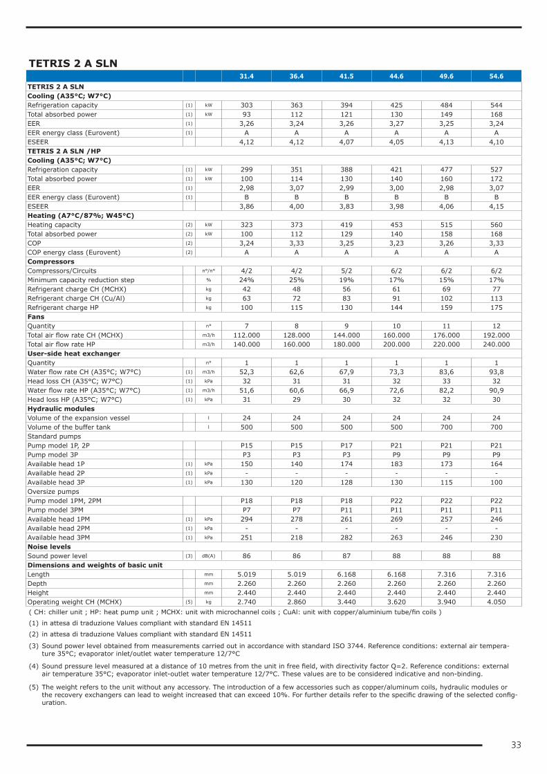
33
TETRIS 2 A SLN 31.4 36.4 41.5 44.6 49.6 54.6TETRIS 2 A SLNCooling (A35°C; W7°C)Refrigeration capacity (1) kW 303 363 394 425 484 544Total absorbed power (1) kW 93 112 121 130 149 168EER (1) 3,26 3,24 3,26 3,27 3,25 3,24EER energy class (Eurovent) (1) A A A A A AESEER 4,12 4,12 4,07 4,05 4,13 4,10TETRIS 2 A SLN /HPCooling (A35°C; W7°C)Refrigeration capacity (1) kW 299 351 388 421 477 527Total absorbed power (1) kW 100 114 130 140 160 172EER (1) 2,98 3,07 2,99 3,00 2,98 3,07EER energy class (Eurovent) (1) B B B B B BESEER 3,86 4,00 3,83 3,98 4,06 4,15Heating (A7°C/87%; W45°C)Heating capacity (2) kW 323 373 419 453 515 560Total absorbed power (2) kW 100 112 129 140 158 168COP (2) 3,24 3,33 3,25 3,23 3,26 3,33COP energy class (Eurovent) (2) A A A A A ACompressorsCompressors/Circuits n°/n° 4/2 4/2 5/2 6/2 6/2 6/2Minimum capacity reduction step % 24% 25% 19% 17% 15% 17%Refrigerant charge CH (MCHX) kg 42 48 56 61 69 77Refrigerant charge CH (Cu/Al) kg 63 72 83 91 102 113Refrigerant charge HP kg 100 115 130 144 159 175FansQuantity n° 7 8 9 10 11 12Total air flow rate CH (MCHX) m3/h 112.000 128.000 144.000 160.000 176.000 192.000Total air flow rate HP m3/h 140.000 160.000 180.000 200.000 220.000 240.000User-side heat exchangerQuantity n° 1 1 1 1 1 1Water flow rate CH (A35°C; W7°C) (1) m3/h 52,3 62,6 67,9 73,3 83,6 93,8Head loss CH (A35°C; W7°C) (1) kPa 32 31 31 32 33 32Water flow rate HP (A35°C; W7°C) (1) m3/h 51,6 60,6 66,9 72,6 82,2 90,9Head loss HP (A35°C; W7°C) (1) kPa 31 29 30 32 32 30Hydraulic modulesVolume of the expansion vessel l 24 24 24 24 24 24Volume of the buffer tank l 500 500 500 500 700 700Standard pumpsPump model 1P, 2P P15 P15 P17 P21 P21 P21Pump model 3P P3 P3 P3 P9 P9 P9Available head 1P (1) kPa 150 140 174 183 173 164Available head 2P (1) kPa - - - - - -Available head 3P (1) kPa 130 120 128 130 115 100Oversize pumpsPump model 1PM, 2PM P18 P18 P18 P22 P22 P22Pump model 3PM P7 P7 P11 P11 P11 P11Available head 1PM (1) kPa 294 278 261 269 257 246Available head 2PM (1) kPa - - - - - -Available head 3PM (1) kPa 251 218 282 263 246 230Noise levelsSound power level (3) dB(A) 86 86 87 88 88 88Dimensions and weights of basic unitLength mm 5.019 5.019 6.168 6.168 7.316 7.316Depth mm 2.260 2.260 2.260 2.260 2.260 2.260Height mm 2.440 2.440 2.440 2.440 2.440 2.440Operating weight CH (MCHX) (5) kg 2.740 2.860 3.440 3.620 3.940 4.050( CH: chiller unit ; HP: heat pump unit ; MCHX: unit with microchannel coils ; CuAl: unit with copper/aluminium tube/fin coils )
(1) in attesa di traduzione Values compliant with standard EN 14511
(2) in attesa di traduzione Values compliant with standard EN 14511
(3) Sound power level obtained from measurements carried out in accordance with standard ISO 3744. Reference conditions: external air tempera-ture 35°C; evaporator inlet/outlet water temperature 12/7°C
(4) Sound pressure level measured at a distance of 10 metres from the unit in free field, with directivity factor Q=2. Reference conditions: external air temperature 35°C; evaporator inlet-outlet water temperature 12/7°C. These values are to be considered indicative and non-binding.
(5) The weight refers to the unit without any accessory. The introduction of a few accessories such as copper/aluminum coils, hydraulic modules or the recovery exchangers can lead to weight increased that can exceed 10%. For further details refer to the specific drawing of the selected config-uration.
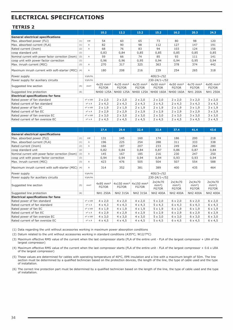
34
ELECTRICAL SPECIFICATIONSTETRIS 2 10.2 12.2 13.2 15.2 16.2 20.3 24.3General electrical specificationsMax. absorbed power (FLI) (1) kW 54 60 65 73 80 98 120Max. absorbed current (FLA) (1) A 82 90 98 112 127 147 191Rated current (Inom) (2) A 68 76 83 94 103 124 156cosφ standard unit (2) 0,83 0,84 0,85 0,85 0,85 0,85 0,85Nominal current with power factor correction (Inom) (2) A 59 66 74 85 93 111 141cosφ unit with power factor correction (2) 0,96 0,96 0,95 0,94 0,94 0,95 0,94Max. inrush current (MIC) (3) A 270 317 325 363 378 374 442
Maximum inrush current with soft-starter (MIC) (4) A 180 208 216 239 254 265 318
Power supply V/ph/Hz 400/3~/52Power supply for auxiliary circuits V/ph/Hz 230-24/1~/52
Suggested line section (5) mm²4x35 mm²
FG7OR4x35 mm²
FG7OR4x35 mm²
FG7OR4x50 mm²
FG7OR4x50 mm²
FG7OR4x70 mm²
FG7OR4x95 mm²
FG7ORSuggested line protection (6) NH00 125A NH00 125A NH00 125A NH00 160A NH00 160A NH1 200A NH1 250AElectrical specifications for fansRated power of fan standard n° x kW 2 x 2,0 2 x 2,0 2 x 2,0 2 x 2,0 2 x 2,0 3 x 2,0 3 x 2,0Rated current of fan standard n° x A 2 x 4,3 2 x 4,3 2 x 4,3 2 x 4,3 2 x 4,3 3 x 4,3 3 x 4,3Rated power of fan EC n° x kW 2 x 1,9 2 x 1,9 2 x 1,9 2 x 1,9 2 x 1,9 3 x 1,9 3 x 1,9Rated current of fan EC n° x A 2 x 2,9 2 x 2,9 2 x 2,9 2 x 2,9 2 x 2,9 3 x 2,9 3 x 2,9Rated power of fan oversize EC n° x kW 2 x 3,0 2 x 3,0 2 x 3,0 2 x 3,0 2 x 3,0 3 x 3,0 3 x 3,0Rated current of fan oversize EC n° x A 2 x 4,5 2 x 4,5 2 x 4,5 2 x 4,5 2 x 4,5 3 x 4,5 3 x 4,5
27.4 29.4 32.4 33.4 37.4 41.4 43.6General electrical specificationsMax. absorbed power (FLI) (1) kW 131 145 160 174 186 200 218Max. absorbed current (FLA) (1) A 196 225 254 288 311 333 338Rated current (Inom) (2) A 166 187 207 233 249 264 280cosφ standard unit (2) 0,82 0,84 0,84 0,87 0,86 0,87 0,84Nominal current with power factor correction (Inom) (2) A 145 167 185 216 230 247 250cosφ unit with power factor correction (2) 0,94 0,94 0,94 0,94 0,93 0,93 0,94Max. inrush current (MIC) (3) A 423 476 505 504 507 554 588
Maximum inrush current with soft-starter (MIC) (4) A 314 352 381 389 400 435 464
Power supply V/ph/Hz 400/3~/52Power supply for auxiliary circuits V/ph/Hz 230-24/1~/52
Suggested line section (5) mm²4x95 mm²
FG7OR4x150 mm²
FG7OR4x150 mm²
FG7OR
2x(4x70 mm²) FG7OR
2x(4x70 mm²) FG7OR
2x(4x70 mm²) FG7OR
2x(4x70 mm²) FG7OR
Suggested line protection (6) NH1 250A NH2 315A NH2 315A NH2 400A NH2 400A NH2 400A NH2 400AElectrical specifications for fansRated power of fan standard n° x kW 4 x 2,0 4 x 2,0 4 x 2,0 5 x 2,0 6 x 2,0 6 x 2,0 6 x 2,0Rated current of fan standard n° x A 4 x 4,3 4 x 4,3 4 x 4,3 5 x 4,3 6 x 4,3 6 x 4,3 6 x 4,3Rated power of fan EC n° x kW 4 x 1,9 4 x 1,9 4 x 1,9 5 x 1,9 6 x 1,9 6 x 1,9 6 x 1,9Rated current of fan EC n° x A 4 x 2,9 4 x 2,9 4 x 2,9 5 x 2,9 6 x 2,9 6 x 2,9 6 x 2,9Rated power of fan oversize EC n° x kW 4 x 3,0 4 x 3,0 4 x 3,0 5 x 3,0 6 x 3,0 6 x 3,0 6 x 3,0Rated current of fan oversize EC n° x A 4 x 4,5 4 x 4,5 4 x 4,5 5 x 4,5 6 x 4,5 6 x 4,5 6 x 4,5
(1) Data regarding the unit without accessories working in maximum power absorption conditions
(2) Datum related to the unit without accessories working in standard conditions (A35°C; W12/7°C)
(3) Maximum effective RMS value of the current when the last compressor starts (FLA of the entire unit - FLA of the largest compressor + LRA of the largest compressor)
(4) Maximum effective RMS value of the current when the last compressor starts (FLA of the entire unit - FLA of the largest compressor + 0.6 x LRA of the largest compressor)
(5) These values are determined for cables with operating temperature of 40°C, EPR insulation and a line with a maximum length of 50m. The line section must be determined by a qualified technician based on the protection devices, the length of the line, the type of cable used and the type of installation.
(6) The correct line protection part must be determined by a qualified technician based on the length of the line, the type of cable used and the type of installation.
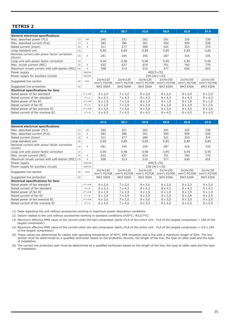
35
TETRIS 2 47.6 50.7 53.8 58.8 62.8 67.9General electrical specificationsMax. absorbed power (FLI) (1) kW 240 251 262 291 320 338Max. absorbed current (FLA) (1) A 382 386 391 450 509 528Rated current (Inom) (2) A 311 277 289 321 353 374cosφ standard unit (2) 0,85 0,85 0,85 0,85 0,85 0,85Nominal current with power factor correction (Inom)
(2) A 281 245 256 287 316 335
cosφ unit with power factor correction (2) 0,94 0,96 0,96 0,95 0,95 0,95Max. inrush current (MIC) (3) A 632 637 619 701 760 779Maximum inrush current with soft-starter (MIC) (4) A 508 513 510 577 636 655Power supply V/ph/Hz 400/3~/52Power supply for auxiliary circuits V/ph/Hz 230-24/1~/52
Suggested line section (5) mm²2x(4x120
mm²) FG7OR2x(4x120
mm²) FG7OR2x(4x120
mm²) FG7OR2x(4x150
mm²) FG7OR2x(4x150
mm²) FG7OR2x(4x150
mm²) FG7ORSuggested line protection (6) NH3 500A NH3 500A NH3 500A NH3 630A NH3 630A NH3 630AElectrical specifications for fansRated power of fan standard n° x kW 6 x 2,0 7 x 2,0 8 x 2,0 8 x 2,0 8 x 2,0 9 x 2,0Rated current of fan standard n° x A 6 x 4,3 7 x 4,3 8 x 4,3 8 x 4,3 8 x 4,3 9 x 4,3Rated power of fan EC n° x kW 6 x 1,9 7 x 1,9 8 x 1,9 8 x 1,9 8 x 1,9 9 x 1,9Rated current of fan EC n° x A 6 x 2,9 7 x 2,9 8 x 2,9 8 x 2,9 8 x 2,9 9 x 2,9Rated power of fan oversize EC n° x kW 6 x 3,0 7 x 3,0 8 x 3,0 8 x 3,0 8 x 3,0 9 x 3,0Rated current of fan oversize EC n° x A 6 x 4,5 7 x 4,5 8 x 4,5 8 x 4,5 8 x 4,5 9 x 4,5
47.6 50.7 53.8 58.8 62.8 67.9General electrical specificationsMax. absorbed power (FLI) (1) kW 240 251 262 291 320 338Max. absorbed current (FLA) (1) A 382 386 391 450 509 528Rated current (Inom) (2) A 311 277 289 321 353 374cosφ standard unit (2) 0,85 0,85 0,85 0,85 0,85 0,85Nominal current with power factor correction (Inom)
(2) A 281 245 256 287 316 335
cosφ unit with power factor correction (2) 0,94 0,96 0,96 0,95 0,95 0,95Max. inrush current (MIC) (3) A 632 637 619 701 760 779Maximum inrush current with soft-starter (MIC) (4) A 508 513 510 577 636 655Power supply V/ph/Hz 400/3~/52Power supply for auxiliary circuits V/ph/Hz 230-24/1~/52
Suggested line section (5) mm²2x(4x120
mm²) FG7OR2x(4x120
mm²) FG7OR2x(4x120
mm²) FG7OR2x(4x150
mm²) FG7OR2x(4x150
mm²) FG7OR2x(4x150
mm²) FG7ORSuggested line protection (6) NH3 500A NH3 500A NH3 500A NH3 630A NH3 630A NH3 630AElectrical specifications for fansRated power of fan standard n° x kW 6 x 2,0 7 x 2,0 8 x 2,0 8 x 2,0 8 x 2,0 9 x 2,0Rated current of fan standard n° x A 6 x 4,3 7 x 4,3 8 x 4,3 8 x 4,3 8 x 4,3 9 x 4,3Rated power of fan EC n° x kW 6 x 1,9 7 x 1,9 8 x 1,9 8 x 1,9 8 x 1,9 9 x 1,9Rated current of fan EC n° x A 6 x 2,9 7 x 2,9 8 x 2,9 8 x 2,9 8 x 2,9 9 x 2,9Rated power of fan oversize EC n° x kW 6 x 3,0 7 x 3,0 8 x 3,0 8 x 3,0 8 x 3,0 9 x 3,0Rated current of fan oversize EC n° x A 6 x 4,5 7 x 4,5 8 x 4,5 8 x 4,5 8 x 4,5 9 x 4,5 (1) Data regarding the unit without accessories working in maximum power absorption conditions(2) Datum related to the unit without accessories working in standard conditions (A35°C; W12/7°C)(3) Maximum effective RMS value of the current when the last compressor starts (FLA of the entire unit - FLA of the largest compressor + LRA of the
largest compressor)(4) Maximum effective RMS value of the current when the last compressor starts (FLA of the entire unit - FLA of the largest compressor + 0.6 x LRA
of the largest compressor)(5) These values are determined for cables with operating temperature of 40°C, EPR insulation and a line with a maximum length of 50m. The line
section must be determined by a qualified technician based on the protection devices, the length of the line, the type of cable used and the type of installation.
(6) The correct line protection part must be determined by a qualified technician based on the length of the line, the type of cable used and the type of installation.
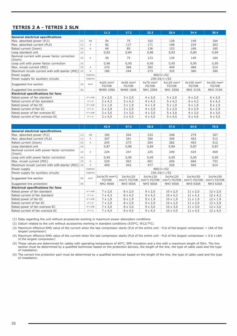
36
TETRIS 2 A - TETRIS 2 SLN 11.2 17.2 23.2 28.4 34.4 38.4General electrical specificationsMax. absorbed power (FLI) (1) kW 54 75 102 128 149 164Max. absorbed current (FLA) (1) A 82 117 171 198 234 263Rated current (Inom) (2) A 69 85 136 153 169 185cosφ standard unit (2) 0,82 0,84 0,86 0,83 0,84 0,84Nominal current with power factor correction (Inom)
(2) A 59 75 123 134 149 164
cosφ unit with power factor correction (2) 0,96 0,95 0,95 0,95 0,95 0,95Max. inrush current (MIC) (3) A 270 368 392 449 484 514Maximum inrush current with soft-starter (MIC) (4) A 180 244 273 325 360 390Power supply V/ph/Hz 400/3~/52Power supply for auxiliary circuits V/ph/Hz 230-24/1~/52
Suggested line section (5) mm²4x25 mm²
FG7OR4x50 mm²
FG7OR4x70 mm²
FG7OR4x120 mm²
FG7OR4x150 mm²
FG7OR4x150 mm²
FG7ORSuggested line protection (6) NH00 100A NH00 160A NH1 200A NH1 250A NH2 315A NH2 315AElectrical specifications for fansRated power of fan standard n° x kW 2 x 2,0 3 x 2,0 4 x 2,0 5 x 2,0 6 x 2,0 6 x 2,0Rated current of fan standard n° x A 2 x 4,3 3 x 4,3 4 x 4,3 5 x 4,3 6 x 4,3 6 x 4,3Rated power of fan EC n° x kW 2 x 1,9 3 x 1,9 4 x 1,9 5 x 1,9 6 x 1,9 6 x 1,9Rated current of fan EC n° x A 2 x 2,9 3 x 2,9 4 x 2,9 5 x 2,9 6 x 2,9 6 x 2,9Rated power of fan oversize EC n° x kW 2 x 3,0 3 x 3,0 4 x 3,0 5 x 3,0 6 x 3,0 6 x 3,0Rated current of fan oversize EC n° x A 2 x 4,5 3 x 4,5 4 x 4,5 5 x 4,5 6 x 4,5 6 x 4,5
43.4 47.4 50.6 57.6 64.6 70.6General electrical specificationsMax. absorbed power (FLI) (1) kW 185 204 224 248 279 307Max. absorbed current (FLA) (1) A 307 341 350 399 463 512Rated current (Inom) (2) A 245 273 254 282 463 512cosφ standard unit (2) 0,87 0,86 0,84 0,84 0,87 0,87Nominal current with power factor correction (Inom)
(2) A 224 247 225 249 424 469
cosφ unit with power factor correction (2) 0,95 0,95 0,95 0,95 0,95 0,95Max. inrush current (MIC) (3) A 529 563 601 650 684 733Maximum inrush current with soft-starter (MIC) (4) A 409 443 477 526 565 614Power supply V/ph/Hz 400/3~/52Power supply for auxiliary circuits V/ph/Hz 230-24/1~/52
Suggested line section (5) mm²2x(4x70 mm²)
FG7OR2x(4x120
mm²) FG7OR2x(4x120
mm²) FG7OR2x(4x120
mm²) FG7OR2x(4x150
mm²) FG7OR2x(4x150
mm²) FG7ORSuggested line protection (6) NH2 400A NH3 500A NH3 500A NH3 500A NH3 630A NH3 630AElectrical specifications for fansRated power of fan standard n° x kW 7 x 2,0 8 x 2,0 9 x 2,0 10 x 2,0 11 x 2,0 12 x 2,0Rated current of fan standard n° x A 7 x 4,3 8 x 4,3 9 x 4,3 10 x 4,3 11 x 4,3 12 x 4,3Rated power of fan EC n° x kW 7 x 1,9 8 x 1,9 9 x 1,9 10 x 1,9 11 x 1,9 12 x 1,9Rated current of fan EC n° x A 7 x 2,9 8 x 2,9 9 x 2,9 10 x 2,9 11 x 2,9 12 x 2,9Rated power of fan oversize EC n° x kW 7 x 3,0 8 x 3,0 9 x 3,0 10 x 3,0 11 x 3,0 12 x 3,0Rated current of fan oversize EC n° x A 7 x 4,5 8 x 4,5 9 x 4,5 10 x 4,5 11 x 4,5 12 x 4,5 (1) Data regarding the unit without accessories working in maximum power absorption conditions(2) Datum related to the unit without accessories working in standard conditions (A35°C; W12/7°C)(3) Maximum effective RMS value of the current when the last compressor starts (FLA of the entire unit - FLA of the largest compressor + LRA of the
largest compressor)(4) Maximum effective RMS value of the current when the last compressor starts (FLA of the entire unit - FLA of the largest compressor + 0.6 x LRA
of the largest compressor)(5) These values are determined for cables with operating temperature of 40°C, EPR insulation and a line with a maximum length of 50m. The line
section must be determined by a qualified technician based on the protection devices, the length of the line, the type of cable used and the type of installation.
(6) The correct line protection part must be determined by a qualified technician based on the length of the line, the type of cable used and the type of installation.
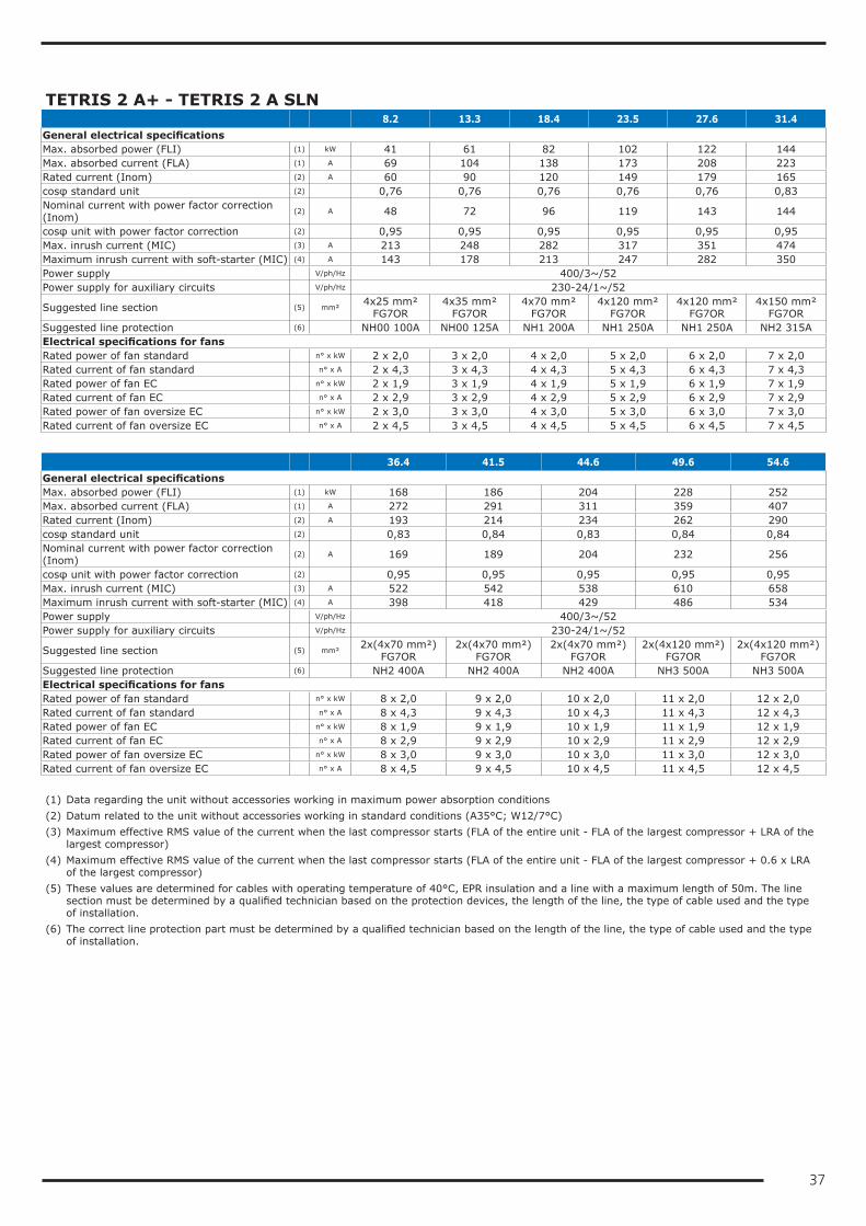
37
TETRIS 2 A+ - TETRIS 2 A SLN 8.2 13.3 18.4 23.5 27.6 31.4General electrical specificationsMax. absorbed power (FLI) (1) kW 41 61 82 102 122 144Max. absorbed current (FLA) (1) A 69 104 138 173 208 223Rated current (Inom) (2) A 60 90 120 149 179 165cosφ standard unit (2) 0,76 0,76 0,76 0,76 0,76 0,83Nominal current with power factor correction (Inom)
(2) A 48 72 96 119 143 144
cosφ unit with power factor correction (2) 0,95 0,95 0,95 0,95 0,95 0,95Max. inrush current (MIC) (3) A 213 248 282 317 351 474Maximum inrush current with soft-starter (MIC) (4) A 143 178 213 247 282 350Power supply V/ph/Hz 400/3~/52Power supply for auxiliary circuits V/ph/Hz 230-24/1~/52
Suggested line section (5) mm²4x25 mm²
FG7OR4x35 mm²
FG7OR4x70 mm²
FG7OR4x120 mm²
FG7OR4x120 mm²
FG7OR4x150 mm²
FG7ORSuggested line protection (6) NH00 100A NH00 125A NH1 200A NH1 250A NH1 250A NH2 315AElectrical specifications for fansRated power of fan standard n° x kW 2 x 2,0 3 x 2,0 4 x 2,0 5 x 2,0 6 x 2,0 7 x 2,0Rated current of fan standard n° x A 2 x 4,3 3 x 4,3 4 x 4,3 5 x 4,3 6 x 4,3 7 x 4,3Rated power of fan EC n° x kW 2 x 1,9 3 x 1,9 4 x 1,9 5 x 1,9 6 x 1,9 7 x 1,9Rated current of fan EC n° x A 2 x 2,9 3 x 2,9 4 x 2,9 5 x 2,9 6 x 2,9 7 x 2,9Rated power of fan oversize EC n° x kW 2 x 3,0 3 x 3,0 4 x 3,0 5 x 3,0 6 x 3,0 7 x 3,0Rated current of fan oversize EC n° x A 2 x 4,5 3 x 4,5 4 x 4,5 5 x 4,5 6 x 4,5 7 x 4,5
36.4 41.5 44.6 49.6 54.6General electrical specificationsMax. absorbed power (FLI) (1) kW 168 186 204 228 252Max. absorbed current (FLA) (1) A 272 291 311 359 407Rated current (Inom) (2) A 193 214 234 262 290cosφ standard unit (2) 0,83 0,84 0,83 0,84 0,84Nominal current with power factor correction (Inom)
(2) A 169 189 204 232 256
cosφ unit with power factor correction (2) 0,95 0,95 0,95 0,95 0,95Max. inrush current (MIC) (3) A 522 542 538 610 658Maximum inrush current with soft-starter (MIC) (4) A 398 418 429 486 534Power supply V/ph/Hz 400/3~/52Power supply for auxiliary circuits V/ph/Hz 230-24/1~/52
Suggested line section (5) mm²2x(4x70 mm²)
FG7OR2x(4x70 mm²)
FG7OR2x(4x70 mm²)
FG7OR2x(4x120 mm²)
FG7OR2x(4x120 mm²)
FG7ORSuggested line protection (6) NH2 400A NH2 400A NH2 400A NH3 500A NH3 500AElectrical specifications for fansRated power of fan standard n° x kW 8 x 2,0 9 x 2,0 10 x 2,0 11 x 2,0 12 x 2,0Rated current of fan standard n° x A 8 x 4,3 9 x 4,3 10 x 4,3 11 x 4,3 12 x 4,3Rated power of fan EC n° x kW 8 x 1,9 9 x 1,9 10 x 1,9 11 x 1,9 12 x 1,9Rated current of fan EC n° x A 8 x 2,9 9 x 2,9 10 x 2,9 11 x 2,9 12 x 2,9Rated power of fan oversize EC n° x kW 8 x 3,0 9 x 3,0 10 x 3,0 11 x 3,0 12 x 3,0Rated current of fan oversize EC n° x A 8 x 4,5 9 x 4,5 10 x 4,5 11 x 4,5 12 x 4,5 (1) Data regarding the unit without accessories working in maximum power absorption conditions(2) Datum related to the unit without accessories working in standard conditions (A35°C; W12/7°C)(3) Maximum effective RMS value of the current when the last compressor starts (FLA of the entire unit - FLA of the largest compressor + LRA of the
largest compressor)(4) Maximum effective RMS value of the current when the last compressor starts (FLA of the entire unit - FLA of the largest compressor + 0.6 x LRA
of the largest compressor)(5) These values are determined for cables with operating temperature of 40°C, EPR insulation and a line with a maximum length of 50m. The line
section must be determined by a qualified technician based on the protection devices, the length of the line, the type of cable used and the type of installation.
(6) The correct line protection part must be determined by a qualified technician based on the length of the line, the type of cable used and the type of installation.
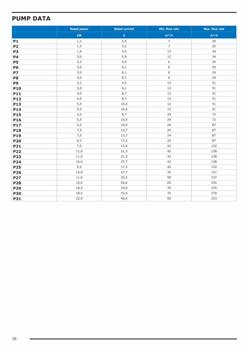
38
PUMP DATA Rated power Rated current Min. flow rate Max. flow rate
kW A m³/h m³/h
P1 1,1 2,5 7 20
P2 1,5 3,2 7 20
P3 1,9 4,5 12 34
P4 3,0 5,9 12 34
P5 2,2 4,5 6 20
P6 3,0 6,1 6 20
P7 3,0 6,1 6 24
P8 4,0 8,7 6 24
P9 2,2 4,5 12 51
P10 3,0 6,1 12 51
P11 4,0 8,7 12 51
P12 4,0 8,7 12 51
P13 5,5 10,4 12 51
P14 5,5 10,4 12 51
P15 4,0 8,7 24 72
P16 5,5 10,4 24 72
P17 5,5 10,4 24 87
P18 7,5 13,7 24 87
P19 7,5 13,7 24 87
P20 9,2 17,2 24 87
P21 7,5 13,6 42 132
P22 11,0 21,3 42 138
P23 11,0 21,3 42 138
P24 15,0 27,7 42 138
P25 9,2 17,2 42 132
P26 15,0 27,7 35 157
P27 11,0 20,2 58 237
P28 15,0 26,6 65 255
P29 18,5 33,0 70 270
P30 18,5 33,0 70 270
P31 22,0 40,4 50 233
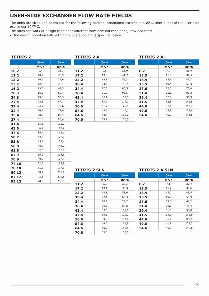
39
USER-SIDE EXCHANGER FLOW RATE FIELDSThe units are sized and optimized for the following nominal conditions: external air 35°C, inlet-outlet of the user-side exchanger 12/7°C.The units can work at design conditions different from nominal conditions, provided that:• the design condition falls within the operating limits specified below
TETRIS 2 Qmin Qmax
m³/h m³/h
10.2 9,4 28,1
12.2 10,2 30,5
13.2 10,9 32,6
15.2 12,0 36,1
16.2 13,8 41,3
20.3 16,8 50,4
24.3 19,8 59,3
27.4 22,6 67,7
29.4 24,2 72,6
32.4 26,3 78,9
33.4 28,8 86,4
37.4 31,8 95,4
41.4 35,1 105,2
43.6 36,7 110,2
47.6 39,4 118,1
50.7 42,3 127,0
53.8 45,1 135,4
58.8 48,9 146,7
62.8 52,6 157,9
67.9 56,2 168,5
70.9 59,2 177,5
74.10 62,0 185,9
78.10 65,7 197,1
80.12 68,4 205,2
87.12 73,6 220,8
93.12 78,8 236,3
TETRIS 2 A Qmin Qmax
m³/h m³/h
11.2 9,6 28,9
17.2 13,9 41,7
23.2 19,8 59,3
28.4 23,6 70,7
34.4 27,8 83,5
38.4 31,2 93,5
43.4 36,1 108,3
47.4 39,2 117,7
50.6 41,7 125,1
57.6 46,7 140,1
64.6 53,4 160,2
70.6 58,9 176,8
TETRIS 2 SLN Qmin Qmax
m³/h m³/h
11.2 9,1 27,3
17.2 13,1 39,3
23.2 18,5 55,6
28.4 22,1 66,3
34.4 26,2 78,7
38.4 29,3 87,8
43.4 33,8 101,5
47.4 36,8 110,3
50.6 39,3 117,8
57.6 44,0 131,9
64.6 50,2 150,5
70.6 55,3 166,0
TETRIS 2 A+ Qmin Qmax
m³/h m³/h
8.2 7,7 23,0
13.3 11,5 34,4
18.4 15,6 46,7
23.5 19,4 58,3
27.6 23,3 70,0
31.4 26,8 80,3
36.4 32,1 96,3
41.5 34,8 104,5
44.6 37,6 112,7
49.6 42,9 128,6
54.6 48,2 144,6
TETRIS 2 A SLN Qmin Qmax
m³/h m³/h
8.2 7,5 22,4
13.3 11,2 33,6
18.4 15,2 45,5
23.5 19,0 56,9
27.6 22,7 68,2
31.4 26,1 78,4
36.4 31,3 93,8
41.5 34,0 101,9
44.6 36,6 109,9
49.6 41,8 125,3
54.6 46,9 140,8
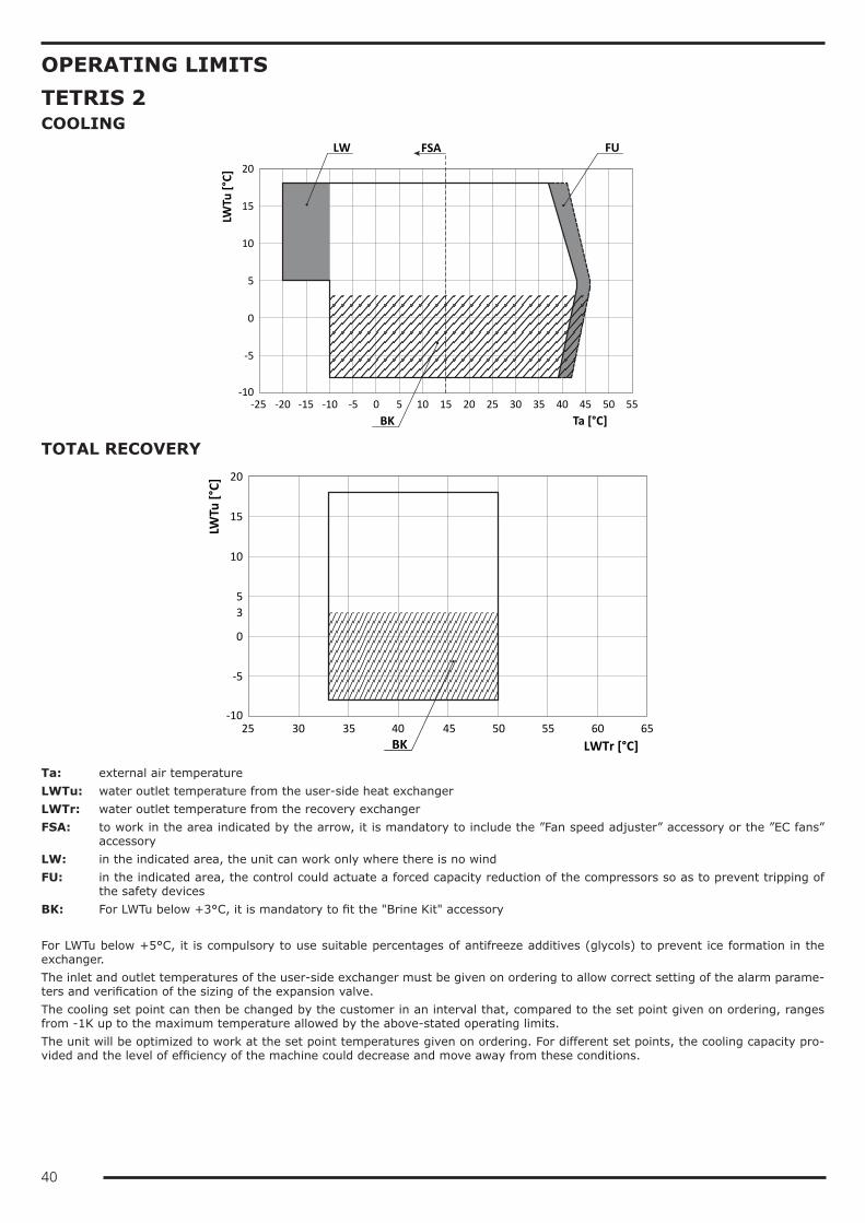
40
OPERATING LIMITSTETRIS 2COOLING
0
5
-10
-5
10
15
20
-25 -20 -15 -10 -5 0 5 10 15 20 25 30 35 40 45 50 55
Ta [°C]
LWTu
[°C]
BK
LW FUFSA
TOTAL RECOVERY
-10
-5
10
15
20
0
53
25 30 35 40 45 50 55 60 65
LWTr [°C]
LWTu
[°C]
BK
Ta: external air temperatureLWTu: water outlet temperature from the user-side heat exchangerLWTr: water outlet temperature from the recovery exchangerFSA: to work in the area indicated by the arrow, it is mandatory to include the ”Fan speed adjuster” accessory or the ”EC fans”
accessoryLW: in the indicated area, the unit can work only where there is no windFU: in the indicated area, the control could actuate a forced capacity reduction of the compressors so as to prevent tripping of
the safety devicesBK: For LWTu below +3°C, it is mandatory to fit the "Brine Kit" accessory For LWTu below +5°C, it is compulsory to use suitable percentages of antifreeze additives (glycols) to prevent ice formation in the exchanger.The inlet and outlet temperatures of the user-side exchanger must be given on ordering to allow correct setting of the alarm parame-ters and verification of the sizing of the expansion valve.The cooling set point can then be changed by the customer in an interval that, compared to the set point given on ordering, ranges from -1K up to the maximum temperature allowed by the above-stated operating limits.The unit will be optimized to work at the set point temperatures given on ordering. For different set points, the cooling capacity pro-vided and the level of efficiency of the machine could decrease and move away from these conditions.
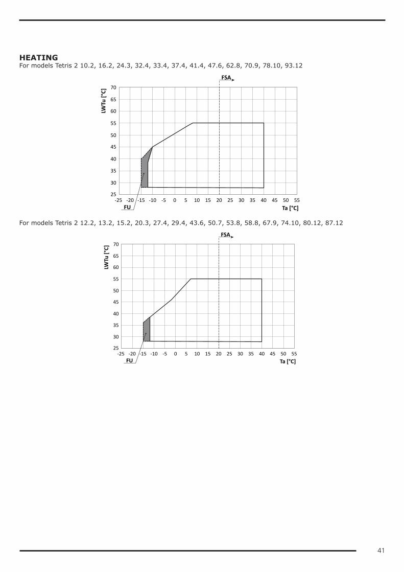
41
HEATINGFor models Tetris 2 10.2, 16.2, 24.3, 32.4, 33.4, 37.4, 41.4, 47.6, 62.8, 70.9, 78.10, 93.12
40
45
50
25
30
35
55
60
65
70
-25 -20 -15 -10 -5 0 5 10 15 20 25 30 35 40 45 50 55
Ta [°C]
LWTu
[°C]
FU
FSA
For models Tetris 2 12.2, 13.2, 15.2, 20.3, 27.4, 29.4, 43.6, 50.7, 53.8, 58.8, 67.9, 74.10, 80.12, 87.12
40
45
50
25
30
35
55
60
65
70
-25 -20 -15 -10 -5 0 5 10 15 20 25 30 35 40 45 50 55
Ta [°C]
LWTu
[°C]
FU
FSA
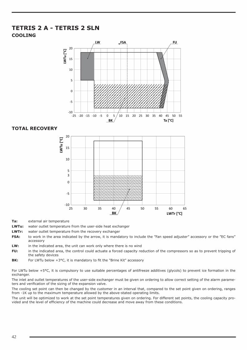
42
TETRIS 2 A - TETRIS 2 SLNCOOLING
0
5
-10
-5
10
15
20
-25 -20 -15 -10 -5 0 5 10 15 20 25 30 35 40 45 50 55
Ta [°C]
LWTu
[°C]
BK
LW FUFSA
TOTAL RECOVERY
-10
-5
10
15
20
0
53
25 30 35 40 45 50 55 60 65
LWTr [°C]
LWTu
[°C]
BK
Ta: external air temperatureLWTu: water outlet temperature from the user-side heat exchangerLWTr: water outlet temperature from the recovery exchangerFSA: to work in the area indicated by the arrow, it is mandatory to include the ”Fan speed adjuster” accessory or the ”EC fans”
accessoryLW: in the indicated area, the unit can work only where there is no windFU: in the indicated area, the control could actuate a forced capacity reduction of the compressors so as to prevent tripping of
the safety devicesBK: For LWTu below +3°C, it is mandatory to fit the "Brine Kit" accessory For LWTu below +5°C, it is compulsory to use suitable percentages of antifreeze additives (glycols) to prevent ice formation in the exchanger.The inlet and outlet temperatures of the user-side exchanger must be given on ordering to allow correct setting of the alarm parame-ters and verification of the sizing of the expansion valve.The cooling set point can then be changed by the customer in an interval that, compared to the set point given on ordering, ranges from -1K up to the maximum temperature allowed by the above-stated operating limits.The unit will be optimized to work at the set point temperatures given on ordering. For different set points, the cooling capacity pro-vided and the level of efficiency of the machine could decrease and move away from these conditions.
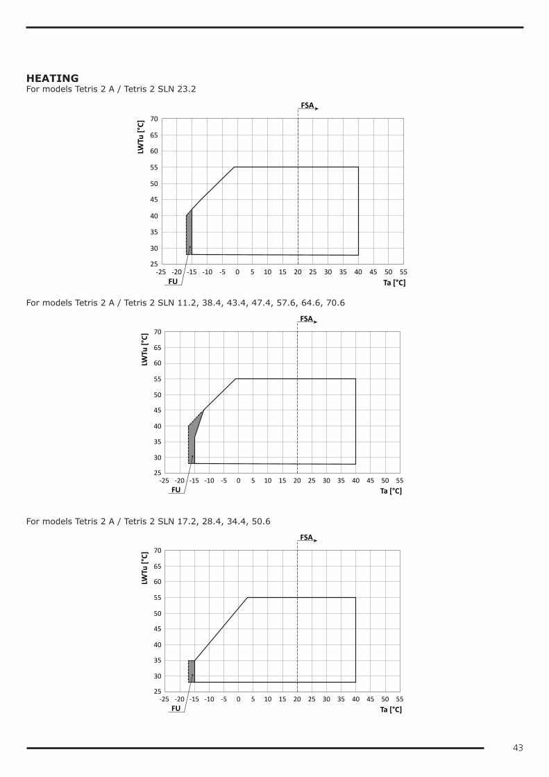
43
HEATINGFor models Tetris 2 A / Tetris 2 SLN 23.2
40
45
50
25
30
35
55
60
65
70
-25 -20 -15 -10 -5 0 5 10 15 20 25 30 35 40 45 50 55
Ta [°C]
LWTu
[°C]
FU
FSA
For models Tetris 2 A / Tetris 2 SLN 11.2, 38.4, 43.4, 47.4, 57.6, 64.6, 70.6
40
45
50
25
30
35
55
60
65
70
-25 -20 -15 -10 -5 0 5 10 15 20 25 30 35 40 45 50 55
Ta [°C]
LWTu
[°C]
FU
FSA
For models Tetris 2 A / Tetris 2 SLN 17.2, 28.4, 34.4, 50.6
40
45
50
25
30
35
55
60
65
70
-25 -20 -15 -10 -5 0 5 10 15 20 25 30 35 40 45 50 55
Ta [°C]
LWTu
[°C]
FU
FSA
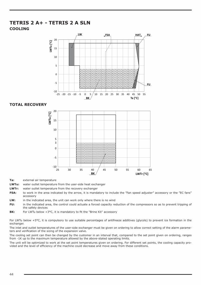
44
TETRIS 2 A+ - TETRIS 2 A SLNCOOLING
0
5
-10
-5
10
15
20
-25 -20 -15 -10 -5 0 5 10 15 20 25 30 35 40 45 50 55
Ta [°C]
LWTu
[°C]
LW
FU
FUFSA HAT
BK
TOTAL RECOVERY
-10
-5
10
15
20
0
53
25 30 35 40 45 50 55 60 65
LWTr [°C]
LWTu
[°C]
BK
Ta: external air temperatureLWTu: water outlet temperature from the user-side heat exchangerLWTr: water outlet temperature from the recovery exchangerFSA: to work in the area indicated by the arrow, it is mandatory to include the ”Fan speed adjuster” accessory or the ”EC fans”
accessoryLW: in the indicated area, the unit can work only where there is no windFU: in the indicated area, the control could actuate a forced capacity reduction of the compressors so as to prevent tripping of
the safety devicesBK: For LWTu below +3°C, it is mandatory to fit the "Brine Kit" accessory For LWTu below +5°C, it is compulsory to use suitable percentages of antifreeze additives (glycols) to prevent ice formation in the exchanger.The inlet and outlet temperatures of the user-side exchanger must be given on ordering to allow correct setting of the alarm parame-ters and verification of the sizing of the expansion valve.The cooling set point can then be changed by the customer in an interval that, compared to the set point given on ordering, ranges from -1K up to the maximum temperature allowed by the above-stated operating limits.The unit will be optimized to work at the set point temperatures given on ordering. For different set points, the cooling capacity pro-vided and the level of efficiency of the machine could decrease and move away from these conditions.
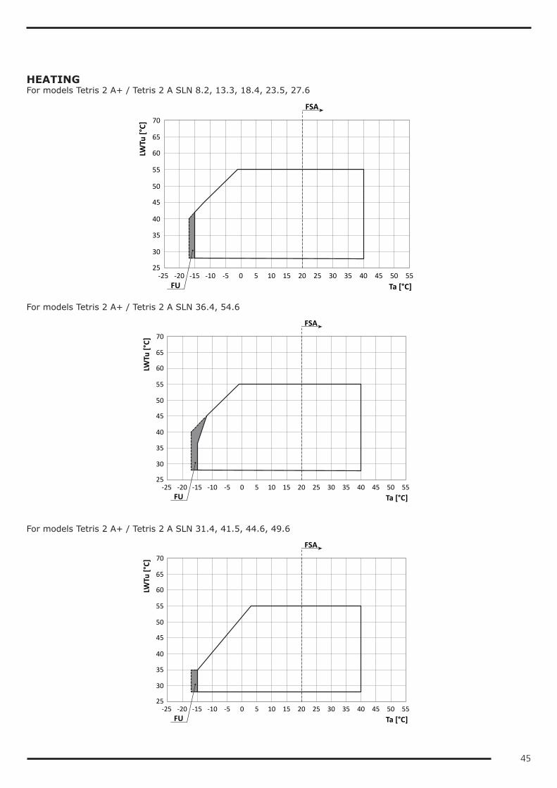
45
HEATINGFor models Tetris 2 A+ / Tetris 2 A SLN 8.2, 13.3, 18.4, 23.5, 27.6
40
45
50
25
30
35
55
60
65
70
-25 -20 -15 -10 -5 0 5 10 15 20 25 30 35 40 45 50 55
Ta [°C]
LWTu
[°C]
FU
FSA
For models Tetris 2 A+ / Tetris 2 A SLN 36.4, 54.6
40
45
50
25
30
35
55
60
65
70
-25 -20 -15 -10 -5 0 5 10 15 20 25 30 35 40 45 50 55
Ta [°C]
LWTu
[°C]
FU
FSA
For models Tetris 2 A+ / Tetris 2 A SLN 31.4, 41.5, 44.6, 49.6
40
45
50
25
30
35
55
60
65
70
-25 -20 -15 -10 -5 0 5 10 15 20 25 30 35 40 45 50 55
Ta [°C]
LWTu
[°C]
FU
FSA
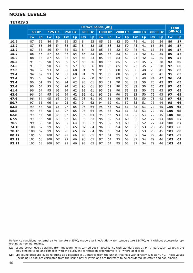
46
NOISE LEVELSTETRIS 2
Octave bands [dB] Total
[dB(A)]63 Hz 125 Hz 250 Hz 500 Hz 1000 Hz 2000 Hz 4000 Hz 8000 HzLw Lp Lw Lp Lw Lp Lw Lp Lw Lp Lw Lp Lw Lp Lw Lp Lw Lp
10.2 87 55 86 54 85 53 84 52 85 53 82 50 73 41 66 34 89 5712.2 87 55 86 54 85 53 84 52 85 53 82 50 73 41 66 34 89 5713.2 87 55 86 54 85 53 84 52 85 53 82 50 73 41 66 34 89 5715.2 88 56 87 55 86 54 85 53 85 53 83 51 74 42 67 35 89 5716.2 88 56 87 55 86 54 85 53 85 53 83 51 74 42 67 35 89 5720.3 91 59 90 58 89 57 88 56 88 56 85 53 77 45 70 38 92 6024.3 91 59 90 58 89 57 88 56 88 56 85 53 77 45 70 38 92 6027.3 94 62 93 61 92 60 91 59 91 59 88 56 80 48 73 41 95 6329.4 94 62 93 61 92 60 91 59 91 59 88 56 80 48 73 41 95 6332.4 95 63 94 62 93 61 92 60 92 60 89 57 81 49 74 42 96 6433.4 96 64 95 63 94 62 93 61 93 61 90 58 82 50 75 43 97 6537.4 96 64 95 63 94 62 93 61 93 61 90 58 82 50 75 43 97 6541.4 96 64 95 63 94 62 93 61 93 61 90 58 82 50 75 43 97 6543.6 96 64 95 63 94 62 93 61 93 61 90 58 82 50 75 43 97 6547.6 96 64 95 63 94 62 93 61 93 61 90 58 82 50 75 43 97 6550.7 97 65 96 64 95 63 94 62 94 62 91 59 83 51 76 44 98 6653.8 99 67 98 66 97 65 96 64 95 63 93 61 85 53 77 45 100 6858.8 99 67 98 66 97 65 96 64 95 63 93 61 85 53 77 45 100 6862.8 99 67 98 66 97 65 96 64 95 63 93 61 85 53 77 45 100 6867.9 99 66 98 65 97 64 96 63 95 62 93 60 85 52 77 44 100 6770.9 99 66 98 65 97 64 96 63 95 62 93 60 85 52 77 44 100 6774.10 100 67 99 66 98 65 97 64 96 63 94 61 86 53 78 45 101 6878.10 100 67 99 66 98 65 97 64 96 63 94 61 86 53 78 45 101 6880.12 101 68 100 67 99 66 98 65 97 64 95 62 87 54 79 46 102 6987.12 101 68 100 67 99 66 98 65 97 64 95 62 87 54 79 46 102 6993.12 101 68 100 67 99 66 98 65 97 64 95 62 87 54 79 46 102 69
Reference conditions: external air temperature 35°C; evaporator inlet/outlet water temperature 12/7°C; unit without accessories op-erating at nominal regime.Lw: sound power levels obtained from measurements carried out in accordance with standard ISO 3744. In particular, Lw tot is the
only binding value and complies with the Eurovent certification programme (8/1) where applicable.Lp: Lp: sound pressure levels referring at a distance of 10 metres from the unit in free field with directivity factor Q=2. These values
(including Lp tot) are calculated from the sound power levels and are therefore to be considered indicative and non-binding.
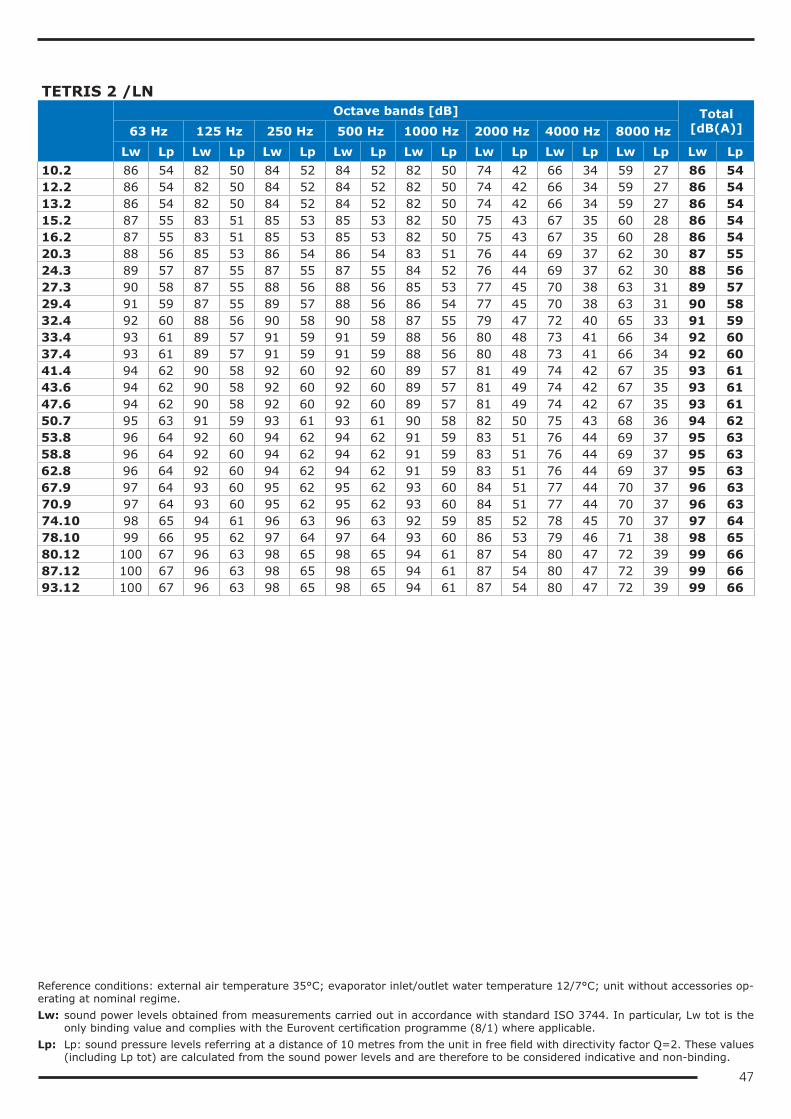
47
TETRIS 2 /LN
Octave bands [dB] Total
[dB(A)]63 Hz 125 Hz 250 Hz 500 Hz 1000 Hz 2000 Hz 4000 Hz 8000 HzLw Lp Lw Lp Lw Lp Lw Lp Lw Lp Lw Lp Lw Lp Lw Lp Lw Lp
10.2 86 54 82 50 84 52 84 52 82 50 74 42 66 34 59 27 86 5412.2 86 54 82 50 84 52 84 52 82 50 74 42 66 34 59 27 86 5413.2 86 54 82 50 84 52 84 52 82 50 74 42 66 34 59 27 86 5415.2 87 55 83 51 85 53 85 53 82 50 75 43 67 35 60 28 86 5416.2 87 55 83 51 85 53 85 53 82 50 75 43 67 35 60 28 86 5420.3 88 56 85 53 86 54 86 54 83 51 76 44 69 37 62 30 87 5524.3 89 57 87 55 87 55 87 55 84 52 76 44 69 37 62 30 88 5627.3 90 58 87 55 88 56 88 56 85 53 77 45 70 38 63 31 89 5729.4 91 59 87 55 89 57 88 56 86 54 77 45 70 38 63 31 90 5832.4 92 60 88 56 90 58 90 58 87 55 79 47 72 40 65 33 91 5933.4 93 61 89 57 91 59 91 59 88 56 80 48 73 41 66 34 92 6037.4 93 61 89 57 91 59 91 59 88 56 80 48 73 41 66 34 92 6041.4 94 62 90 58 92 60 92 60 89 57 81 49 74 42 67 35 93 6143.6 94 62 90 58 92 60 92 60 89 57 81 49 74 42 67 35 93 6147.6 94 62 90 58 92 60 92 60 89 57 81 49 74 42 67 35 93 6150.7 95 63 91 59 93 61 93 61 90 58 82 50 75 43 68 36 94 6253.8 96 64 92 60 94 62 94 62 91 59 83 51 76 44 69 37 95 6358.8 96 64 92 60 94 62 94 62 91 59 83 51 76 44 69 37 95 6362.8 96 64 92 60 94 62 94 62 91 59 83 51 76 44 69 37 95 6367.9 97 64 93 60 95 62 95 62 93 60 84 51 77 44 70 37 96 6370.9 97 64 93 60 95 62 95 62 93 60 84 51 77 44 70 37 96 6374.10 98 65 94 61 96 63 96 63 92 59 85 52 78 45 70 37 97 6478.10 99 66 95 62 97 64 97 64 93 60 86 53 79 46 71 38 98 6580.12 100 67 96 63 98 65 98 65 94 61 87 54 80 47 72 39 99 6687.12 100 67 96 63 98 65 98 65 94 61 87 54 80 47 72 39 99 6693.12 100 67 96 63 98 65 98 65 94 61 87 54 80 47 72 39 99 66
Reference conditions: external air temperature 35°C; evaporator inlet/outlet water temperature 12/7°C; unit without accessories op-erating at nominal regime.Lw: sound power levels obtained from measurements carried out in accordance with standard ISO 3744. In particular, Lw tot is the
only binding value and complies with the Eurovent certification programme (8/1) where applicable.Lp: Lp: sound pressure levels referring at a distance of 10 metres from the unit in free field with directivity factor Q=2. These values
(including Lp tot) are calculated from the sound power levels and are therefore to be considered indicative and non-binding.
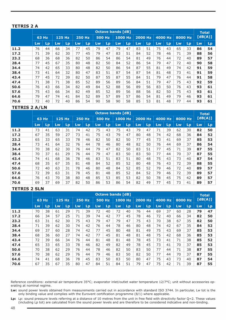
48
TETRIS 2 A
Octave bands [dB] Total
[dB(A)]63 Hz 125 Hz 250 Hz 500 Hz 1000 Hz 2000 Hz 4000 Hz 8000 HzLw Lp Lw Lp Lw Lp Lw Lp Lw Lp Lw Lp Lw Lp Lw Lp Lw Lp
11.2 76 44 66 34 77 45 79 47 79 47 83 51 75 43 65 33 86 5417.2 71 39 62 30 77 45 79 47 83 51 84 52 78 46 71 39 88 5623.2 68 36 68 36 82 50 86 54 86 54 81 49 76 44 72 40 89 5728.4 77 45 67 35 80 48 82 50 84 52 86 54 79 47 72 40 90 5834.4 74 42 65 33 80 48 82 50 86 54 87 55 81 49 74 42 91 5938.4 73 41 64 32 80 47 83 51 87 54 87 54 81 48 73 41 91 5943.4 77 45 72 39 82 50 87 55 87 55 84 51 79 47 76 44 91 5847.4 71 38 71 38 85 52 89 56 89 56 84 51 79 47 75 43 92 5950.6 76 43 66 34 82 49 84 52 88 56 89 56 83 50 76 43 93 6157.6 75 43 66 34 82 49 85 52 89 56 88 56 82 50 75 43 93 6164.6 79 47 74 41 84 52 89 57 89 57 86 54 81 49 79 46 93 6170.6 72 40 72 40 86 54 90 58 90 58 85 53 81 48 77 44 93 61
TETRIS 2 A/LN
Octave bands [dB] Total
[dB(A)]63 Hz 125 Hz 250 Hz 500 Hz 1000 Hz 2000 Hz 4000 Hz 8000 HzLw Lp Lw Lp Lw Lp Lw Lp Lw Lp Lw Lp Lw Lp Lw Lp Lw Lp
11.2 73 41 63 31 74 42 75 43 75 43 79 47 71 39 62 30 82 5017.2 67 35 59 27 73 41 75 43 79 47 80 48 74 42 68 36 84 5223.2 65 33 65 33 78 46 82 50 82 50 77 45 73 41 69 37 85 5328.4 73 41 64 32 76 44 78 46 80 48 82 50 76 44 69 37 86 5434.4 70 38 62 30 76 44 79 47 82 50 83 51 77 45 71 39 87 5538.4 70 37 61 29 76 44 79 47 83 50 83 50 77 44 70 37 87 5543.4 74 41 68 36 78 46 83 51 83 51 80 48 75 43 73 40 87 5447.4 68 35 67 35 81 48 84 52 85 52 80 48 76 43 72 39 88 5550.6 72 40 63 31 78 46 80 48 84 52 85 52 79 46 72 40 89 5757.6 72 39 63 31 78 45 81 48 85 52 84 52 79 46 72 39 89 5764.6 76 43 70 38 80 48 85 53 85 53 82 50 78 45 75 42 89 5770.6 69 37 69 37 82 50 86 53 86 54 82 49 77 45 73 41 89 57
TETRIS 2 SLN
Octave bands [dB] Total
[dB(A)]63 Hz 125 Hz 250 Hz 500 Hz 1000 Hz 2000 Hz 4000 Hz 8000 HzLw Lp Lw Lp Lw Lp Lw Lp Lw Lp Lw Lp Lw Lp Lw Lp Lw Lp
11.2 70 38 61 29 71 39 72 40 72 40 76 44 69 37 60 28 79 4717.2 66 34 57 25 71 39 74 42 77 45 78 46 72 40 66 34 82 5023.2 63 31 62 30 75 43 79 47 79 47 75 43 70 38 67 35 82 5028.4 71 39 62 30 74 42 76 44 78 46 80 48 74 42 67 35 84 5234.4 69 37 60 28 74 42 77 45 80 48 81 49 75 43 69 37 85 5338.4 68 36 60 27 74 42 77 45 81 48 81 48 75 42 68 36 85 5343.4 72 39 66 34 76 44 81 48 81 48 78 45 73 41 71 38 85 5247.4 65 33 65 33 78 46 82 49 82 49 78 45 73 41 70 37 85 5350.6 70 38 62 29 76 44 78 46 82 50 83 50 77 44 71 38 87 5557.6 70 38 62 29 76 44 79 46 83 50 82 50 77 44 70 37 87 5564.6 74 41 68 36 78 45 83 50 83 50 80 47 75 43 73 40 87 5470.6 67 35 67 35 80 47 84 51 84 51 79 47 75 42 71 39 87 55
Reference conditions: external air temperature 35°C; evaporator inlet/outlet water temperature 12/7°C; unit without accessories op-erating at nominal regime.Lw: sound power levels obtained from measurements carried out in accordance with standard ISO 3744. In particular, Lw tot is the
only binding value and complies with the Eurovent certification programme (8/1) where applicable.Lp: Lp: sound pressure levels referring at a distance of 10 metres from the unit in free field with directivity factor Q=2. These values
(including Lp tot) are calculated from the sound power levels and are therefore to be considered indicative and non-binding.
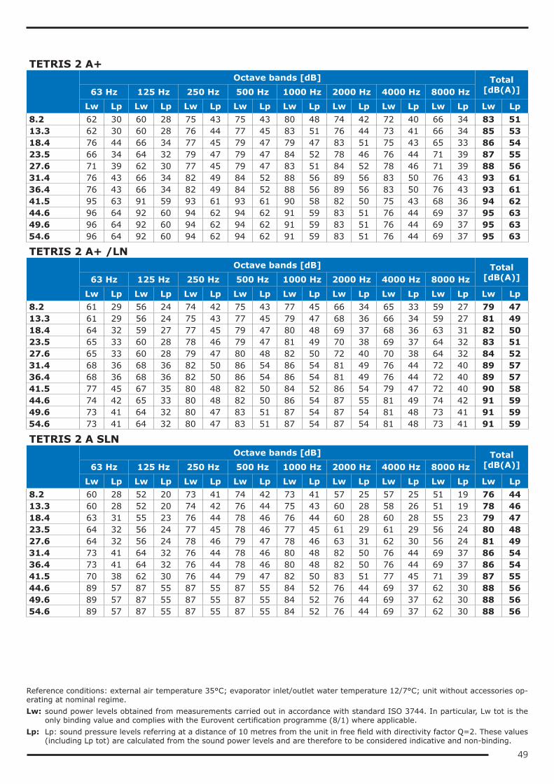
49
TETRIS 2 A+
Octave bands [dB] Total
[dB(A)]63 Hz 125 Hz 250 Hz 500 Hz 1000 Hz 2000 Hz 4000 Hz 8000 HzLw Lp Lw Lp Lw Lp Lw Lp Lw Lp Lw Lp Lw Lp Lw Lp Lw Lp
8.2 62 30 60 28 75 43 75 43 80 48 74 42 72 40 66 34 83 5113.3 62 30 60 28 76 44 77 45 83 51 76 44 73 41 66 34 85 5318.4 76 44 66 34 77 45 79 47 79 47 83 51 75 43 65 33 86 5423.5 66 34 64 32 79 47 79 47 84 52 78 46 76 44 71 39 87 5527.6 71 39 62 30 77 45 79 47 83 51 84 52 78 46 71 39 88 5631.4 76 43 66 34 82 49 84 52 88 56 89 56 83 50 76 43 93 6136.4 76 43 66 34 82 49 84 52 88 56 89 56 83 50 76 43 93 6141.5 95 63 91 59 93 61 93 61 90 58 82 50 75 43 68 36 94 6244.6 96 64 92 60 94 62 94 62 91 59 83 51 76 44 69 37 95 6349.6 96 64 92 60 94 62 94 62 91 59 83 51 76 44 69 37 95 6354.6 96 64 92 60 94 62 94 62 91 59 83 51 76 44 69 37 95 63
TETRIS 2 A+ /LN
Octave bands [dB] Total
[dB(A)]63 Hz 125 Hz 250 Hz 500 Hz 1000 Hz 2000 Hz 4000 Hz 8000 HzLw Lp Lw Lp Lw Lp Lw Lp Lw Lp Lw Lp Lw Lp Lw Lp Lw Lp
8.2 61 29 56 24 74 42 75 43 77 45 66 34 65 33 59 27 79 4713.3 61 29 56 24 75 43 77 45 79 47 68 36 66 34 59 27 81 4918.4 64 32 59 27 77 45 79 47 80 48 69 37 68 36 63 31 82 5023.5 65 33 60 28 78 46 79 47 81 49 70 38 69 37 64 32 83 5127.6 65 33 60 28 79 47 80 48 82 50 72 40 70 38 64 32 84 5231.4 68 36 68 36 82 50 86 54 86 54 81 49 76 44 72 40 89 5736.4 68 36 68 36 82 50 86 54 86 54 81 49 76 44 72 40 89 5741.5 77 45 67 35 80 48 82 50 84 52 86 54 79 47 72 40 90 5844.6 74 42 65 33 80 48 82 50 86 54 87 55 81 49 74 42 91 5949.6 73 41 64 32 80 47 83 51 87 54 87 54 81 48 73 41 91 5954.6 73 41 64 32 80 47 83 51 87 54 87 54 81 48 73 41 91 59
TETRIS 2 A SLN
Octave bands [dB] Total
[dB(A)]63 Hz 125 Hz 250 Hz 500 Hz 1000 Hz 2000 Hz 4000 Hz 8000 HzLw Lp Lw Lp Lw Lp Lw Lp Lw Lp Lw Lp Lw Lp Lw Lp Lw Lp
8.2 60 28 52 20 73 41 74 42 73 41 57 25 57 25 51 19 76 4413.3 60 28 52 20 74 42 76 44 75 43 60 28 58 26 51 19 78 4618.4 63 31 55 23 76 44 78 46 76 44 60 28 60 28 55 23 79 4723.5 64 32 56 24 77 45 78 46 77 45 61 29 61 29 56 24 80 4827.6 64 32 56 24 78 46 79 47 78 46 63 31 62 30 56 24 81 4931.4 73 41 64 32 76 44 78 46 80 48 82 50 76 44 69 37 86 5436.4 73 41 64 32 76 44 78 46 80 48 82 50 76 44 69 37 86 5441.5 70 38 62 30 76 44 79 47 82 50 83 51 77 45 71 39 87 5544.6 89 57 87 55 87 55 87 55 84 52 76 44 69 37 62 30 88 5649.6 89 57 87 55 87 55 87 55 84 52 76 44 69 37 62 30 88 5654.6 89 57 87 55 87 55 87 55 84 52 76 44 69 37 62 30 88 56
Reference conditions: external air temperature 35°C; evaporator inlet/outlet water temperature 12/7°C; unit without accessories op-erating at nominal regime.Lw: sound power levels obtained from measurements carried out in accordance with standard ISO 3744. In particular, Lw tot is the
only binding value and complies with the Eurovent certification programme (8/1) where applicable.Lp: Lp: sound pressure levels referring at a distance of 10 metres from the unit in free field with directivity factor Q=2. These values
(including Lp tot) are calculated from the sound power levels and are therefore to be considered indicative and non-binding.
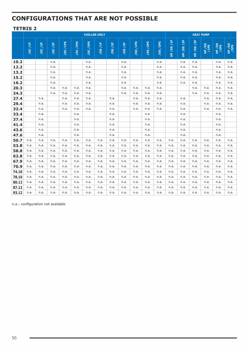
50
CONFIGURATIONS THAT ARE NOT POSSIBLETETRIS 2 CHILLER ONLY HEAT PUMP
/DC
/1P
/DC
/2P
/DC
/3P
/DC
/1PS
/DC
/2PS
/DC
/3PS
/DS
/1P
/DS
/2P
/DS
/3P
/DS
/1PS
/DS
/2PS
/DS
/3PS
HP
/DS
/1P
HP
/DS
/2P
HP
/DS
/3P
HP
/DS
/1PS
HP
/DS
/2PS
HP
/DS
/3PS
10.2 n.a. n.a. n.a. n.a. n.a. n.a. n.a. n.a.
12.2 n.a. n.a. n.a. n.a. n.a. n.a. n.a. n.a.
13.2 n.a. n.a. n.a. n.a. n.a. n.a. n.a. n.a.
15.2 n.a. n.a. n.a. n.a. n.a. n.a. n.a. n.a.
16.2 n.a. n.a. n.a. n.a. n.a. n.a. n.a. n.a.
20.3 n.a. n.a. n.a. n.a. n.a. n.a. n.a. n.a. n.a. n.a. n.a. n.a.
24.3 n.a. n.a. n.a. n.a. n.a. n.a. n.a. n.a. n.a. n.a. n.a. n.a.
27.4 n.a. n.a. n.a. n.a. n.a. n.a. n.a. n.a. n.a. n.a. n.a. n.a.
29.4 n.a. n.a. n.a. n.a. n.a. n.a. n.a. n.a. n.a. n.a. n.a. n.a.
32.4 n.a. n.a. n.a. n.a. n.a. n.a. n.a. n.a. n.a. n.a. n.a. n.a.
33.4 n.a. n.a. n.a. n.a. n.a. n.a.
37.4 n.a. n.a. n.a. n.a. n.a. n.a.
41.4 n.a. n.a. n.a. n.a. n.a. n.a.
43.6 n.a. n.a. n.a. n.a. n.a. n.a.
47.6 n.a. n.a. n.a. n.a. n.a. n.a.
50.7 n.a. n.a. n.a. n.a. n.a. n.a. n.a. n.a. n.a. n.a. n.a. n.a. n.a. n.a. n.a. n.a. n.a. n.a.
53.8 n.a. n.a. n.a. n.a. n.a. n.a. n.a. n.a. n.a. n.a. n.a. n.a. n.a. n.a. n.a. n.a. n.a. n.a.
58.8 n.a. n.a. n.a. n.a. n.a. n.a. n.a. n.a. n.a. n.a. n.a. n.a. n.a. n.a. n.a. n.a. n.a. n.a.
62.8 n.a. n.a. n.a. n.a. n.a. n.a. n.a. n.a. n.a. n.a. n.a. n.a. n.a. n.a. n.a. n.a. n.a. n.a.
67.9 n.a. n.a. n.a. n.a. n.a. n.a. n.a. n.a. n.a. n.a. n.a. n.a. n.a. n.a. n.a. n.a. n.a. n.a.
70.9 n.a. n.a. n.a. n.a. n.a. n.a. n.a. n.a. n.a. n.a. n.a. n.a. n.a. n.a. n.a. n.a. n.a. n.a.
74.10 n.a. n.a. n.a. n.a. n.a. n.a. n.a. n.a. n.a. n.a. n.a. n.a. n.a. n.a. n.a. n.a. n.a. n.a.
78.10 n.a. n.a. n.a. n.a. n.a. n.a. n.a. n.a. n.a. n.a. n.a. n.a. n.a. n.a. n.a. n.a. n.a. n.a.
80.12 n.a. n.a. n.a. n.a. n.a. n.a. n.a. n.a. n.a. n.a. n.a. n.a. n.a. n.a. n.a. n.a. n.a. n.a.
87.12 n.a. n.a. n.a. n.a. n.a. n.a. n.a. n.a. n.a. n.a. n.a. n.a. n.a. n.a. n.a. n.a. n.a. n.a.
93.12 n.a. n.a. n.a. n.a. n.a. n.a. n.a. n.a. n.a. n.a. n.a. n.a. n.a. n.a. n.a. n.a. n.a. n.a.
n.a.: configuration not available
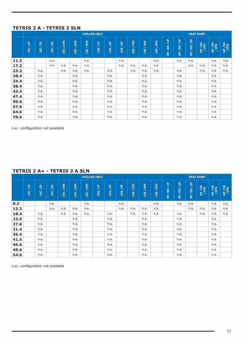
51
TETRIS 2 A - TETRIS 2 SLN CHILLER ONLY HEAT PUMP
/DC
/1P
/DC
/2P
/DC
/3P
/DC
/1PS
/DC
/2PS
/DC
/3PS
/DS
/1P
/DS
/2P
/DS
/3P
/DS
/1PS
/DS
/2PS
/DS
/3PS
HP
/DS
/1P
HP
/DS
/2P
HP
/DS
/3P
HP
/DS
/1PS
HP
/DS
/2PS
HP
/DS
/3PS
11.2 n.a. n.a. n.a. n.a. n.a. n.a. n.a. n.a.
17.2 n.a. n.a. n.a. n.a. n.a. n.a. n.a. n.a. n.a. n.a. n.a. n.a.
23.2 n.a. n.a. n.a. n.a. n.a. n.a. n.a. n.a. n.a. n.a. n.a. n.a.
28.4 n.a. n.a. n.a. n.a. n.a. n.a.
34.4 n.a. n.a. n.a. n.a. n.a. n.a.
38.4 n.a. n.a. n.a. n.a. n.a. n.a.
43.4 n.a. n.a. n.a. n.a. n.a. n.a.
47.4 n.a. n.a. n.a. n.a. n.a. n.a.
50.6 n.a. n.a. n.a. n.a. n.a. n.a.
57.6 n.a. n.a. n.a. n.a. n.a. n.a.
64.6 n.a. n.a. n.a. n.a. n.a. n.a.
70.6 n.a. n.a. n.a. n.a. n.a. n.a.
n.a.: configuration not available
TETRIS 2 A+ - TETRIS 2 A SLN CHILLER ONLY HEAT PUMP
/DC
/1P
/DC
/2P
/DC
/3P
/DC
/1PS
/DC
/2PS
/DC
/3PS
/DS
/1P
/DS
/2P
/DS
/3P
/DS
/1PS
/DS
/2PS
/DS
/3PS
HP
/DS
/1P
HP
/DS
/2P
HP
/DS
/3P
HP
/DS
/1PS
HP
/DS
/2PS
HP
/DS
/3PS
8.2 n.a. n.a. n.a. n.a. n.a. n.a. n.a. n.a.
13.3 n.a. n.a. n.a. n.a. n.a. n.a. n.a. n.a. n.a. n.a. n.a. n.a.
18.4 n.a. n.a. n.a. n.a. n.a. n.a. n.a. n.a. n.a. n.a. n.a. n.a.
23.5 n.a. n.a. n.a. n.a. n.a. n.a.
27.6 n.a. n.a. n.a. n.a. n.a. n.a.
31.4 n.a. n.a. n.a. n.a. n.a. n.a.
36.4 n.a. n.a. n.a. n.a. n.a. n.a.
41.5 n.a. n.a. n.a. n.a. n.a. n.a.
46.6 n.a. n.a. n.a. n.a. n.a. n.a.
49.6 n.a. n.a. n.a. n.a. n.a. n.a.
54.6 n.a. n.a. n.a. n.a. n.a. n.a.
n.a.: configuration not available
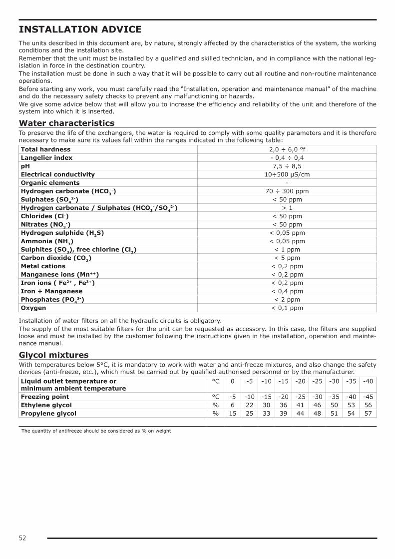
52
INSTALLATION ADVICEThe units described in this document are, by nature, strongly affected by the characteristics of the system, the working conditions and the installation site.Remember that the unit must be installed by a qualified and skilled technician, and in compliance with the national leg-islation in force in the destination country.The installation must be done in such a way that it will be possible to carry out all routine and non-routine maintenance operations.Before starting any work, you must carefully read the “Installation, operation and maintenance manual” of the machine and do the necessary safety checks to prevent any malfunctioning or hazards.We give some advice below that will allow you to increase the efficiency and reliability of the unit and therefore of the system into which it is inserted.
Water characteristicsTo preserve the life of the exchangers, the water is required to comply with some quality parameters and it is therefore necessary to make sure its values fall within the ranges indicated in the following table:Total hardness 2,0 ÷ 6,0 °fLangelier index - 0,4 ÷ 0,4pH 7,5 ÷ 8,5Electrical conductivity 10÷500 µS/cmOrganic elements -Hydrogen carbonate (HCO3
-) 70 ÷ 300 ppmSulphates (SO4
2-) < 50 ppmHydrogen carbonate / Sulphates (HCO3
-/SO42-) > 1
Chlorides (Cl-) < 50 ppmNitrates (NO3
-) < 50 ppmHydrogen sulphide (H2S) < 0,05 ppmAmmonia (NH3) < 0,05 ppmSulphites (SO3), free chlorine (Cl2) < 1 ppmCarbon dioxide (CO2) < 5 ppmMetal cations < 0,2 ppmManganese ions (Mn++) < 0,2 ppmIron ions ( Fe2+ , Fe3+) < 0,2 ppmIron + Manganese < 0,4 ppmPhosphates (PO4
3-) < 2 ppmOxygen < 0,1 ppm
Installation of water filters on all the hydraulic circuits is obligatory.The supply of the most suitable filters for the unit can be requested as accessory. In this case, the filters are supplied loose and must be installed by the customer following the instructions given in the installation, operation and mainte-nance manual.
Glycol mixturesWith temperatures below 5°C, it is mandatory to work with water and anti-freeze mixtures, and also change the safety devices (anti-freeze, etc.), which must be carried out by qualified authorised personnel or by the manufacturer.Liquid outlet temperature or minimum ambient temperature
°C 0 -5 -10 -15 -20 -25 -30 -35 -40
Freezing point °C -5 -10 -15 -20 -25 -30 -35 -40 -45Ethylene glycol % 6 22 30 36 41 46 50 53 56Propylene glycol % 15 25 33 39 44 48 51 54 57
The quantity of antifreeze should be considered as % on weight
53
Minimum water content in the systemFor correct operation of the unit, it is necessary to ensure a buffering on the system such as to comply with the min-imum operating time considering the greater between the minimum OFF time and the minimum ON time. In short, these contribute to limiting the number of times the compressors are switched on per hour and to preventing undesired deviations from the set point of the delivered water temperature.
whereVmin is the minimum water content of the system measured in lPtot is the total cooling capacity of the machine measured in kWN is the number of capacity reduction stepsΔΤ is the differential allowed on the water temperature. Unless otherwise specified, this value is considered to be 2.5Kρ is the density of the heat-carrying fluid. Unless otherwise specified, the density of water is considered and therefore 1000kg/m³cp is the specific heat of the heat-carrying fluid. Unless otherwise specified, the specific heat of water is considered and therefore 4.186kJ/(kgK)Considering the use of water and grouping together some terms, the formula can be re-written as follows:
N is equal to the number of compressors installed in the unit.
54
Installation siteTo determine the best installation site for the unit and its orientation, you should pay attention to the following points:• compliance with the clearance spaces indicated in the official dimensional drawing of the unit must be guaranteed so
as to ensure accessibility for routine and non-routine maintenance operations• you should consider the origin of the hydraulic pipes and their diameters because these affect the radiuses of curva-
ture and therefore the spaces needed for installing them• you should consider the position of the cable inlet on the electrical control panel of the unit as regards the origin of
the power supply• if the installation includes several units side by side, you should consider the position and dimensions of the manifolds
of the user-side exchangers and of any recovery exchangers• if the installation includes several units side by side, you should consider that the minimum distance between units
is 3 metres• you should avoid all obstructions that can limit air circulation to the source-side exchanger or that can cause recircu-
lation between air supply and intake• you should consider the orientation of the unit to limit, as far as possible, exposure of the source-side exchanger to
solar radiation• if the installation area is particularly windy, the orientation and positioning of the unit must be such as to avoid air
recirculation on the coils. If necessary, we advise making windbreak barriers in order to prevent malfunctioning.Once the best position for the unit has been identified, you must check that the support slab has the following charac-teristics:• its dimensions must be proportionate to those of the unit: if possible, longer and wider than the unit by at least 30
cm and 15/20cm higher than the surrounding surface• it must be able to bear at least 4 times the operating weight of the unit• it must allow level installation of the unit: although the unit is installed on a horizontal base, make slopes in the sup-
port surface to convey rain water or defrost water to drains, wells or in any case to places where it cannot generate an accident hazard due to ice formation. All heat pump version units are equipped with discharge manifolds for the condensed water; these can be manifolded to facilitate condensate discharge.
The units are designed and built to reduce to a minimum the level of vibration transmitted to the ground, but it is in any case advisable to use rubber or spring anti-vibration mounts, which are available as accessory and should be requested when ordering.The anti-vibration mounts must be fixed on before positioning the unit on the ground.In the event of installation on roofs or intermediate floors, the pipes must be isolated from the walls and ceilings.It is advisable to avoid installation in cramped places, to prevent reverberations, reflections, resonances and acoustic interactions with elements outside the unit.It is essential that any work done to soundproof the unit does not affect its correct installation or correct operation and, in particular, does not reduce the air flow rate to the source-side exchanger.

55
Installations that require the use of treated coilsIf the unit has to be installed in an environment with a particularly aggressive atmosphere, coils with special treatments are available as options.• e-coated microchannel coils (accessory not available for HP units)• pre-painted aluminium coils (accessory available only for HP units)• coils with anti-corrosion treatment (accessory available only for units with Cu/Al coil or HP units)A description of the individual accessories is available in the “Description of accessories” section.The type of coil treatment should be chosen with regard to the environment in which the unit is to be installed, through observation of other structures and machinery with exposed metal surfaces present in the destination environment.The cross observation criterion is the most valid method of selection currently available without having to carry out preliminary tests or measurements with instruments. The identified reference environments are:• coastal/marine• industrial• urban with a high housing density• ruralPlease note that in cases where different conditions co-exist, even for short periods, the choice must be suitable for preserving the exchanger in the harsher environmental conditions and not in conditions between the worst and best situation.Particular attention must be given in cases where an environment that is not particularly aggressive becomes aggressive as a consequence of a concomitant cause, for example, the presence of a flue outlet or an extraction fan.We strongly suggest choosing one of the treatment options if at least one of the points listed below is verified:• there are obvious signs of corrosion of the exposed metal surfaces in the installation area• the prevailing winds come from the sea towards the unit• the environment is industrial with a significant concentration of pollutants• the environment is urban with a high population density• the environment is rural with the presence of organic discharges and effluentsIn particular, for installations near the coast, the following instructions apply:• for installations between 1 and 20 km from the coast of units with microchannel coil, we strongly recommend using
the accessory "E-coated microchannel coils"• for installations between 1 and 20 km from the coast of reversible units or units with Cu/Al coils, we strongly recom-
mend using the accessory "Coil treated with anti-corrosion paints"• for distances within a kilometre of the coast, we strongly recommend using the accessory "Coil treated with anti-cor-
rosion paints" for all units.To protect the exchangers from corrosion and ensure optimal operation of the unit, we advise following the recommen-dations given in the user, installation and maintenance manual for cleaning the coils.
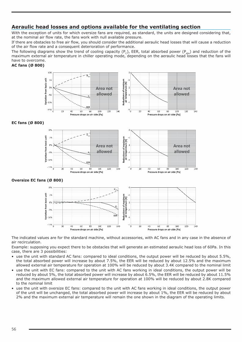
56
Aeraulic head losses and options available for the ventilating sectionWith the exception of units for which oversize fans are required, as standard, the units are designed considering that, at the nominal air flow rate, the fans work with null available pressure.If there are obstacles to free air flow, you should consider the additional aeraulic head losses that will cause a reduction of the air flow rate and a consequent deterioration of performance.The following diagrams show the trend of cooling capacity (PC), EER, total absorbed power (Pabs) and reduction of the maximum external air temperature in chiller operating mode, depending on the aeraulic head losses that the fans will have to overcome.AC fans (Ø 800)
EC fans (Ø 800)
Oversize EC fans (Ø 800)
The indicated values are for the standard machine, without accessories, with AC fans and in any case in the absence of air recirculation.Example: supposing you expect there to be obstacles that will generate an estimated aeraulic head loss of 60Pa. In this case, there are 3 possibilities:• use the unit with standard AC fans: compared to ideal conditions, the output power will be reduced by about 5.5%,
the total absorbed power will increase by about 7.5%, the EER will be reduced by about 12.5% and the maximum allowed external air temperature for operation at 100% will be reduced by about 3.4K compared to the nominal limit
• use the unit with EC fans: compared to the unit with AC fans working in ideal conditions, the output power will be reduced by about 5%, the total absorbed power will increase by about 6.5%, the EER will be reduced by about 11.5% and the maximum allowed external air temperature for operation at 100% will be reduced by about 2.8K compared to the nominal limit
• use the unit with oversize EC fans: compared to the unit with AC fans working in ideal conditions, the output power of the unit will be unchanged, the total absorbed power will increase by about 1%, the EER will be reduced by about 2% and the maximum external air temperature will remain the one shown in the diagram of the operating limits.
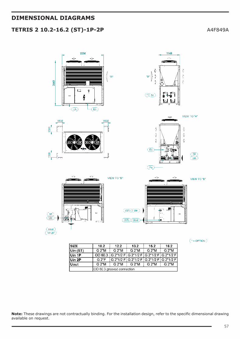
57
DIMENSIONAL DIAGRAMS
TETRIS 2 10.2-16.2 (ST)-1P-2P A4F849A
Note: These drawings are not contractually binding. For the installation design, refer to the specific dimensional drawing available on request.
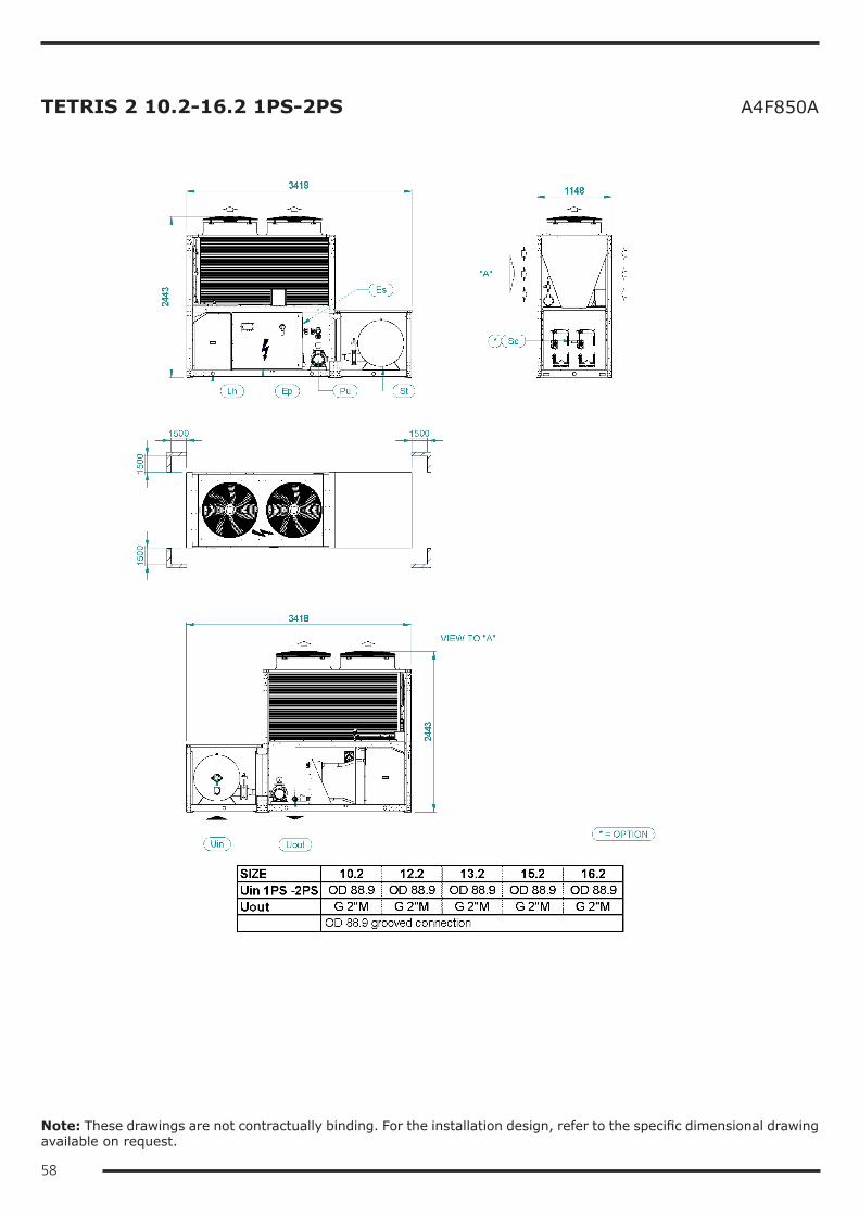
58
TETRIS 2 10.2-16.2 1PS-2PS A4F850A
Note: These drawings are not contractually binding. For the installation design, refer to the specific dimensional drawing available on request.
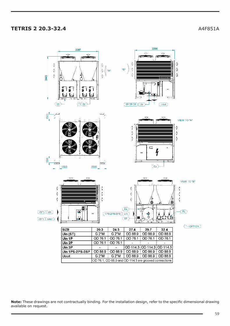
59
TETRIS 2 20.3-32.4 A4F851A
Note: These drawings are not contractually binding. For the installation design, refer to the specific dimensional drawing available on request.
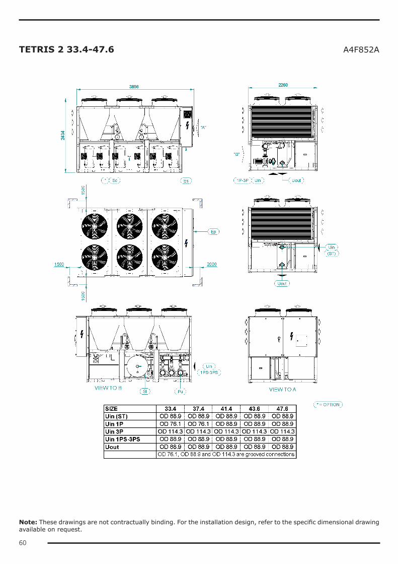
60
TETRIS 2 33.4-47.6 A4F852A
Note: These drawings are not contractually binding. For the installation design, refer to the specific dimensional drawing available on request.
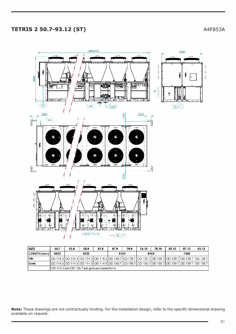
61
TETRIS 2 50.7-93.12 (ST) A4F853A
Note: These drawings are not contractually binding. For the installation design, refer to the specific dimensional drawing available on request.
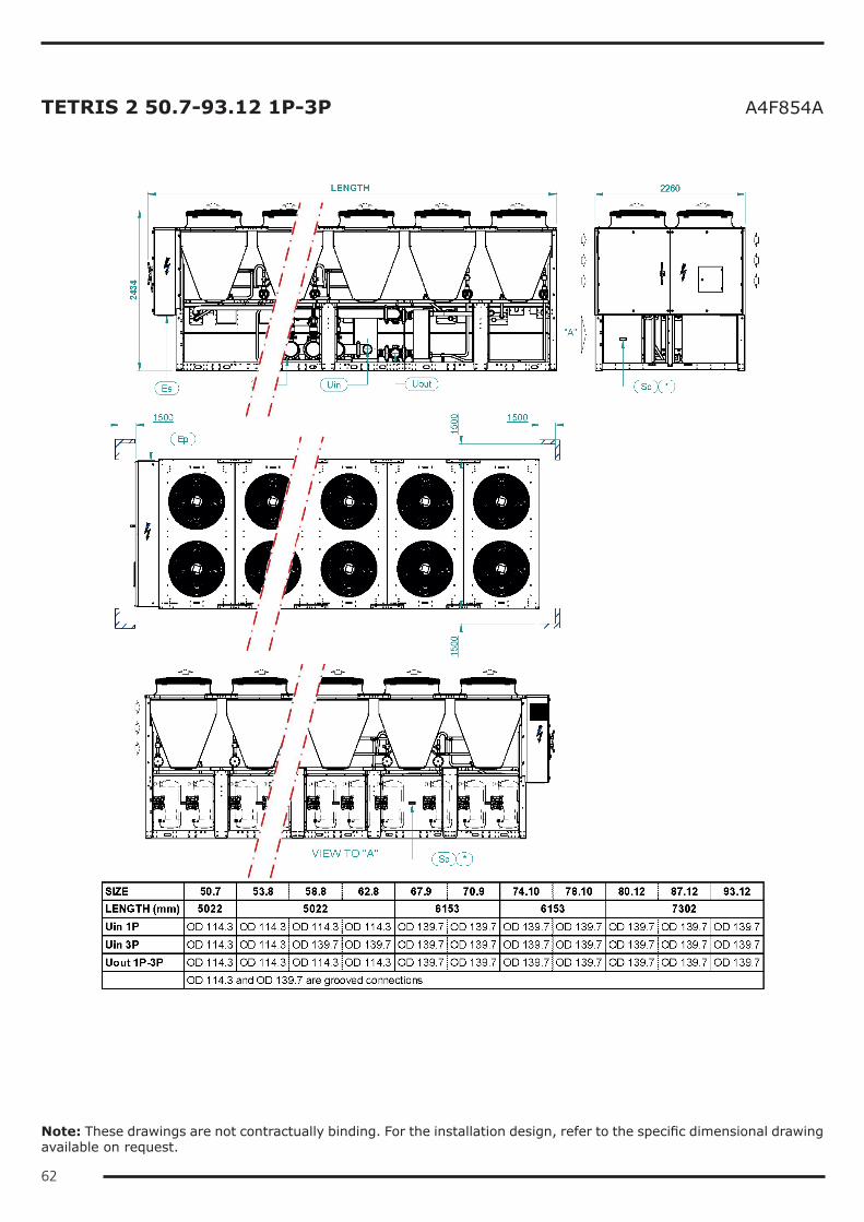
62
TETRIS 2 50.7-93.12 1P-3P A4F854A
Note: These drawings are not contractually binding. For the installation design, refer to the specific dimensional drawing available on request.
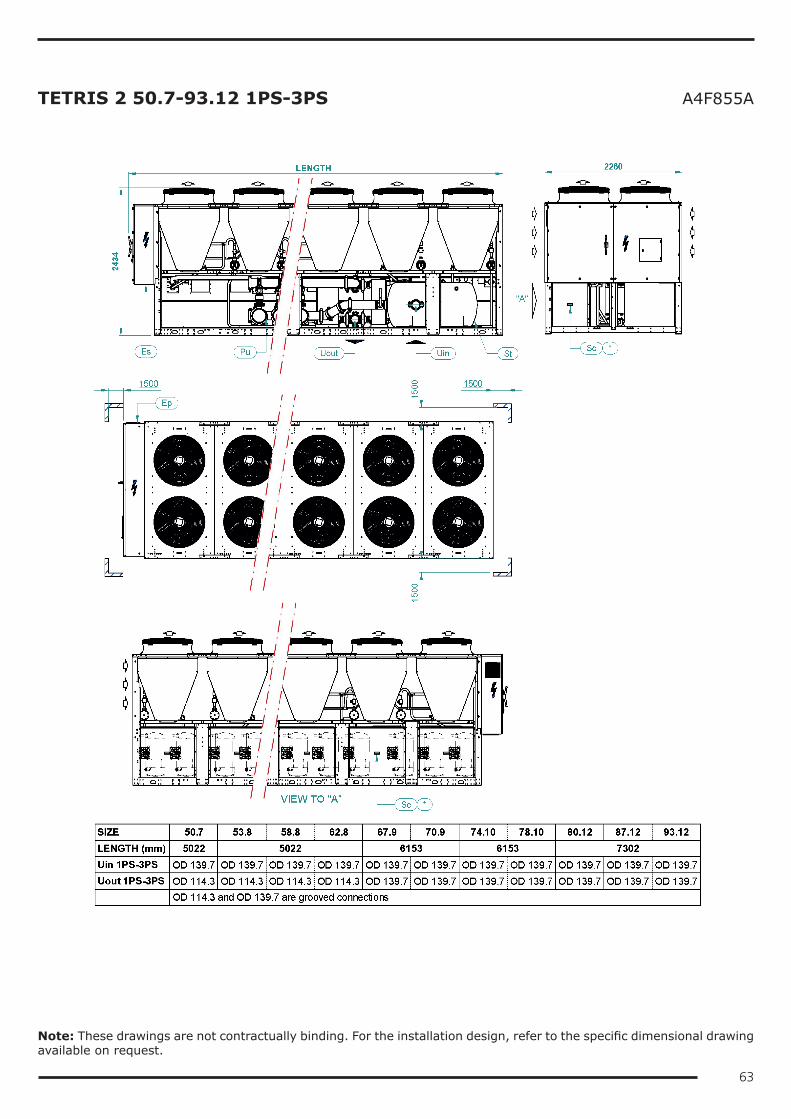
63
TETRIS 2 50.7-93.12 1PS-3PS A4F855A
Note: These drawings are not contractually binding. For the installation design, refer to the specific dimensional drawing available on request.
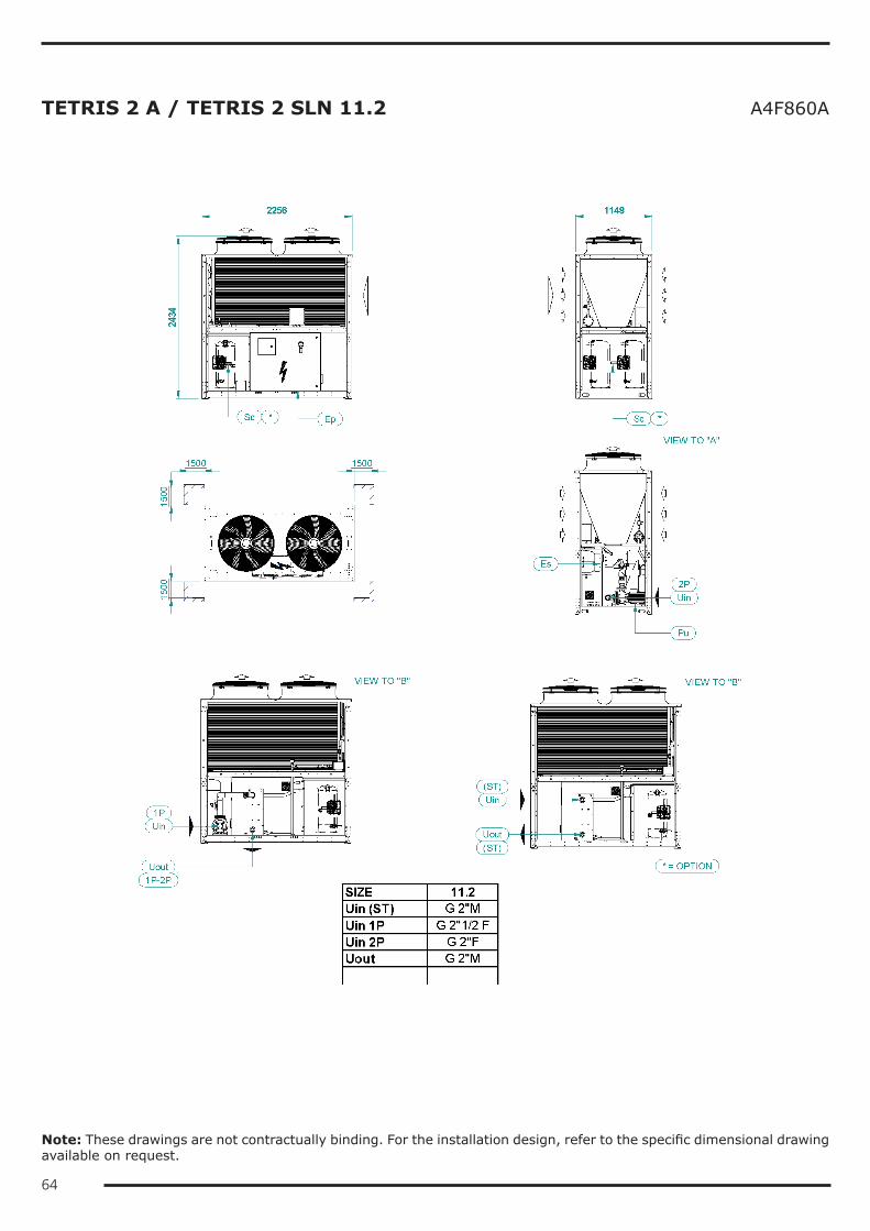
64
TETRIS 2 A / TETRIS 2 SLN 11.2 A4F860A
Note: These drawings are not contractually binding. For the installation design, refer to the specific dimensional drawing available on request.
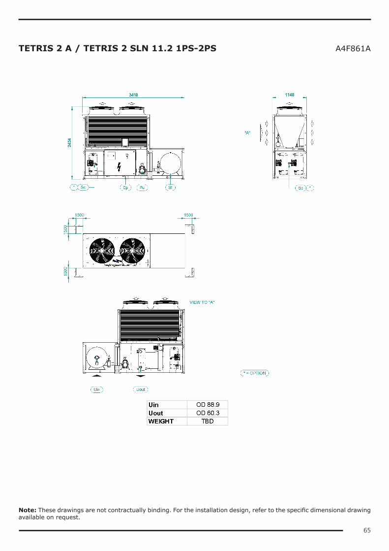
65
TETRIS 2 A / TETRIS 2 SLN 11.2 1PS-2PS A4F861A
Note: These drawings are not contractually binding. For the installation design, refer to the specific dimensional drawing available on request.
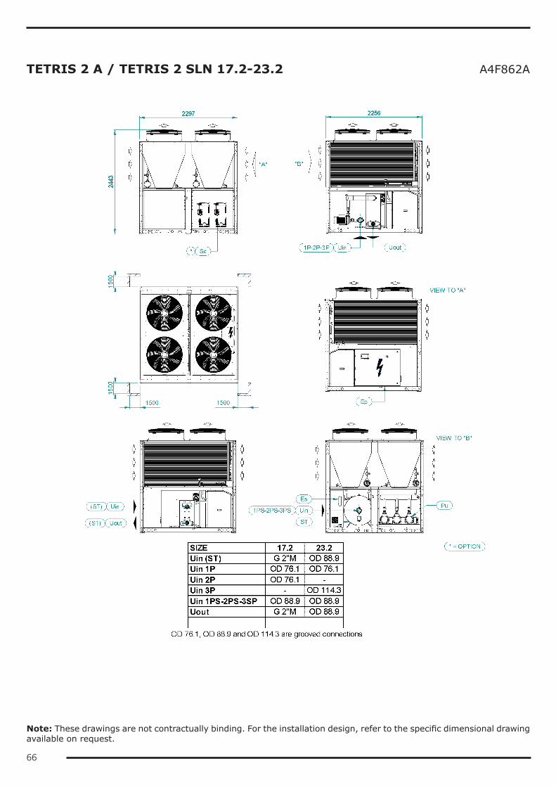
66
TETRIS 2 A / TETRIS 2 SLN 17.2-23.2 A4F862A
Note: These drawings are not contractually binding. For the installation design, refer to the specific dimensional drawing available on request.

67
TETRIS 2 A / TETRIS 2 SLN 28.4 - 70.6 A4F862A
Note: These drawings are not contractually binding. For the installation design, refer to the specific dimensional drawing available on request.
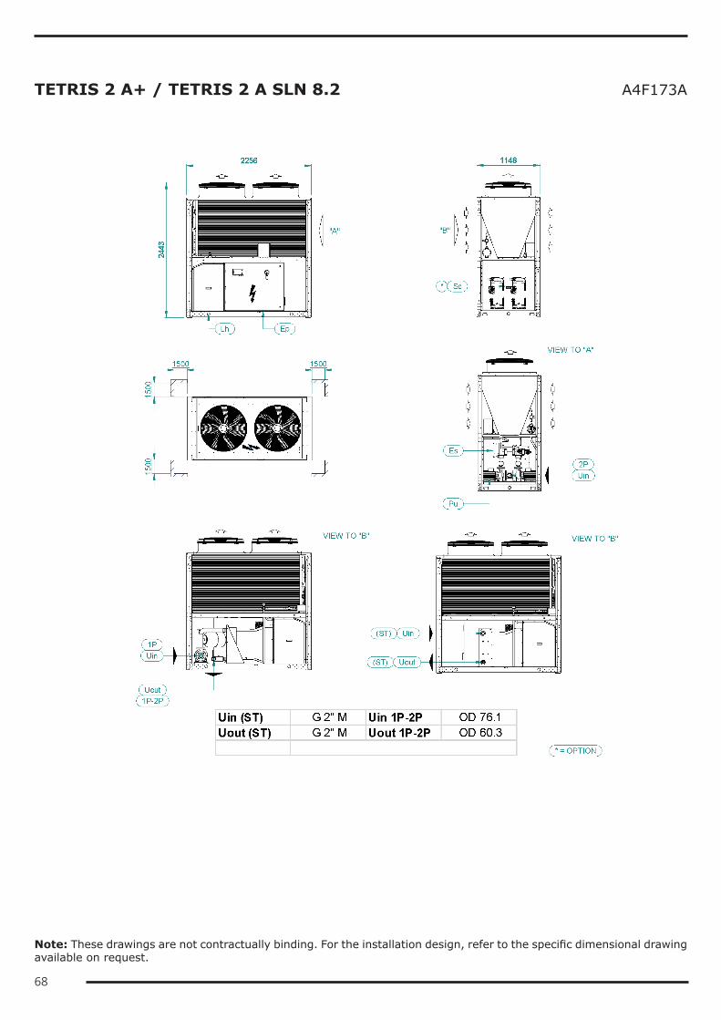
68
TETRIS 2 A+ / TETRIS 2 A SLN 8.2 A4F173A
Note: These drawings are not contractually binding. For the installation design, refer to the specific dimensional drawing available on request.
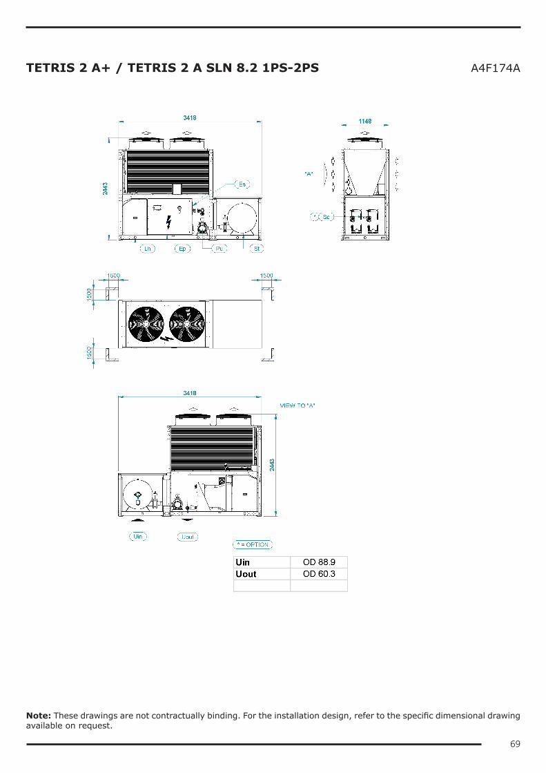
69
TETRIS 2 A+ / TETRIS 2 A SLN 8.2 1PS-2PS A4F174A
Note: These drawings are not contractually binding. For the installation design, refer to the specific dimensional drawing available on request.
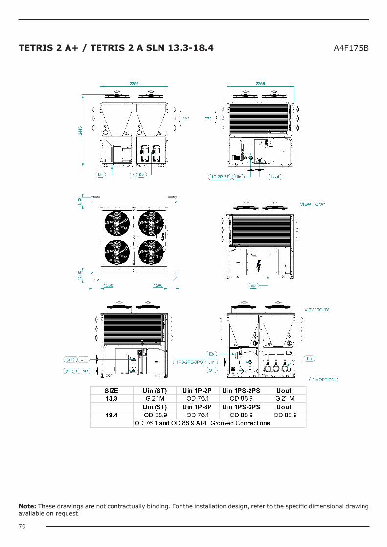
70
TETRIS 2 A+ / TETRIS 2 A SLN 13.3-18.4 A4F175B
Note: These drawings are not contractually binding. For the installation design, refer to the specific dimensional drawing available on request.
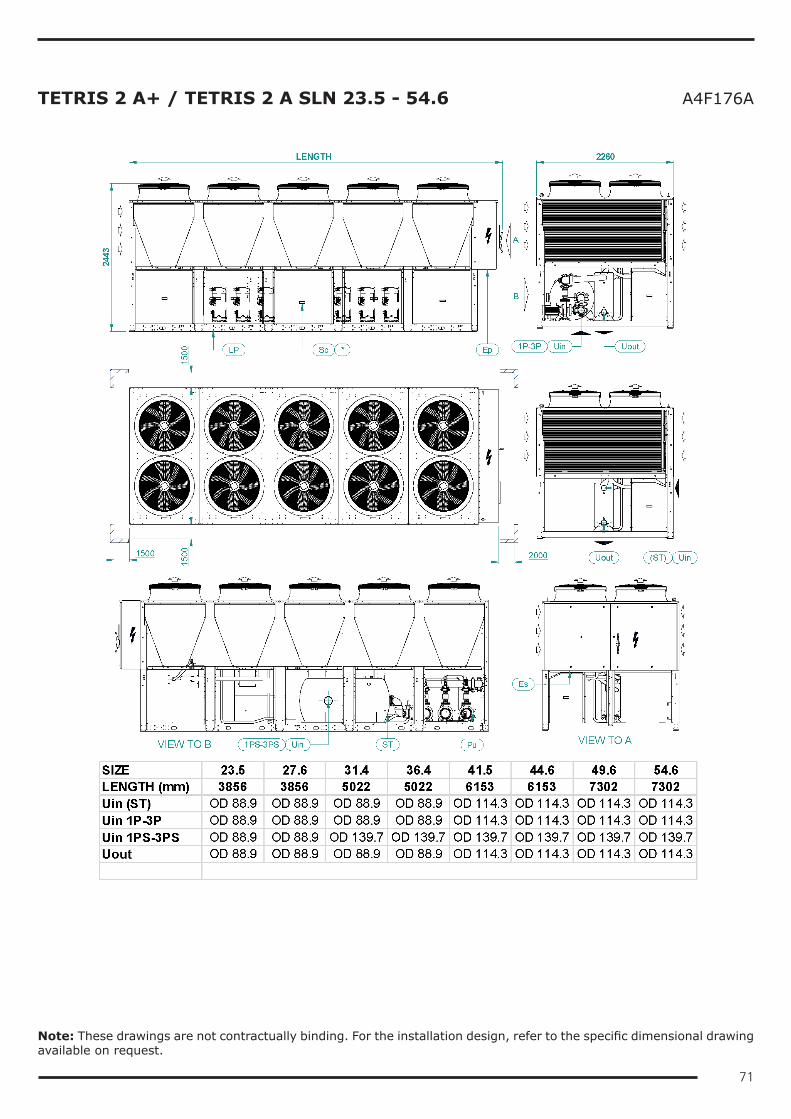
71
TETRIS 2 A+ / TETRIS 2 A SLN 23.5 - 54.6 A4F176A
Note: These drawings are not contractually binding. For the installation design, refer to the specific dimensional drawing available on request.

72


TC_0
000_
T2_E
N_R
ev02
_201
7030
3
Blue Box Group S.r.l.Via Valletta, 5 - 30010Cantarana di Cona, (VE) Italy - T. +39 0426 921111 - F. +39 0426 302222www.blueboxcooling.com - [email protected]
Blue Box Group S.r.l. a socio unico - P.IVA 02481290282Company directed and coordinated by Investment Latour (Sweden)