text marking on parts - volvo
TRANSCRIPT

Standard STD 5051,16 Volvo Group
Issue date May 2020 Issue 17 Page 1 (50)
The English language version is the original and the reference in case of dispute.
MARKING AND DESIGNATIONS
Text marking on parts Marking of parts
Orientation
This issue differs from issue 16 in that:
- it has been clarified that the standard covers both Volvo Group brands as well as joint venture brands.
- the standard has been restructured (rearranged) for better readability.
- section 3.3 has been revised to comply with European competition legislation.
- sections 6.6 and 6.7, which describe free-text marking and supplementary marking, respectively, have been added.
- the option to perform the VOLVO PENTA marking on a single line has been added in section 8.4.
- the Nova Bus logo has been updated.
- the reference to figures for date clock in table 3 have been changed from 4a and 5a to 3a and 4a, respectively.
- the ARQUUS brand marking has been added in section 8.

Standard STD 5051,16 Volvo Group
Issue 17 Page 2 (50)
Contents
1 Scope and field of application ......................................................................................................... 3
2 Terms and definitions ....................................................................................................................... 3
3 Location and visibility....................................................................................................................... 3 3.1 General ................................................................................................................................................ 3 3.2 Volvo Group and joint venture brand markings ................................................................................... 3 3.3 Supplier brand marking – when applicable ......................................................................................... 4 3.4 Supplier serial number ........................................................................................................................ 4
4 Indication of marking in design-engineering documentation ...................................................... 4
5 Marking methods ............................................................................................................................... 6
6 Basic markings .................................................................................................................................. 7 6.1 Volvo brand marking ........................................................................................................................... 8 6.2 Part number ......................................................................................................................................... 8 6.3 Country of origin .................................................................................................................................. 8 6.4 Special requirements for the United States ........................................................................................ 8 6.5 Designations ........................................................................................................................................ 8 6.6 Free-text marking ................................................................................................................................ 9 6.7 Supplementary marking ...................................................................................................................... 9
7 Supplementary markings ............................................................................................................... 12
8 Brand marking and text requirements .......................................................................................... 15 8.1 Relative position of brand marking and text on marked part ............................................................ 16 8.2 Text style for other text ...................................................................................................................... 16 8.3 Colours .............................................................................................................................................. 17 8.4 VOLVO and VOLVO PENTA ............................................................................................................ 17 8.5 UD TRUCKS ..................................................................................................................................... 20 8.6 SDLG ................................................................................................................................................. 24 8.7 RENAULT TRUCKS .......................................................................................................................... 26 8.8 PREVOST ......................................................................................................................................... 29 8.9 NOVABUS ......................................................................................................................................... 30 8.10 MACK ................................................................................................................................................ 31 8.11 EICHER ............................................................................................................................................. 35 8.12 ARQUUS ........................................................................................................................................... 38
9 Associated standards ..................................................................................................................... 42
Appendix A Marking examples ............................................................................................................. 43
Appendix B Discontinued basic markings .......................................................................................... 47
Appendix C Discontinued supplementary markings .......................................................................... 48
Appendix D Discontinued Volvo wordmark sizes ............................................................................... 50

Standard STD 5051,16 Volvo Group
Issue 17 Page 3 (50)
1 Scope and field of application
This standard specifies how parts shall be marked or branded. Which parts shall be marked and what information the marking shall contain is not addressed here, as this is decided in local instructions at the respective Volvo Group entity.
The standard applies to direct marking on parts. In relevant sections, it may also be used for indirect marking, such as marking of packages.
Marking may include Aftermarket branding levels 1–3, in accordance with the Brand Distinction and Aftermarket Tool (BDAT), when requested by either a Volvo Group brand or a joint venture brand.
In cases where the supplier shall specify a supplier-part marking in the supplier-provided documentation, in accordance with this standard, such marking shall be specified upon request from and require the approval of the Volvo Group.
If the manufacturer needs to put their own marking on a part, for example to facilitate handling, this can be accepted by the responsible Volvo Group entity on condition that the function of the part is not jeopardized. However, this marking shall be placed completely separate from the Volvo Group entity marking. The supplier’s marking shall be approved by the Volvo Group entity.
2 Terms and definitions
Volvo Group brand marking
In this standard Volvo Group brand marking refers to marking with one of the various brands within the Volvo Group.
Joint venture brand marking
In this standard joint venture brand marking refers to marking with one of the various brands in which the Volvo Group is engaged through an alliance or a joint venture partnership.
3 Location and visibility
3.1 General
The marking shall be located in such a way that the function of the part is not affected and the marking must be legible when required.
Any application of the Volvo Group product emblems and wordmark logotypes must be approved by Product Design and Aftermarket brand representatives.
3.2 Volvo Group and joint venture brand markings
When a Volvo Group or joint venture brand marking is required it shall be located in a visible area of the
part.
The marking shall be proportional in size to the physical size of the part and the area where it is located.
The area selected shall be non-critical and should not be affected by further processing or assembly
requirements.
Standard STD 5051,16 Volvo Group
Issue 17 Page 4 (50)
3.3 Supplier brand marking – when applicable
When a manufacturer/supplier with reference to legislation requires the presence of their trademark/logotype on a part, the Volvo Group shall require compliance with the following conditions for this to happen:
The size and location of all supplier-brand markings shall be approved by the respective Volvo Group brand representatives.
Only tier-1 supplier brand markings may appear.
The Volvo Group or joint venture brand marking must be equally prominent or more prominent than the tier-1 supplier’s marking, irrespective of where the component is installed in the vehicle.
The tier-1 supplier’s brand marking shall be clearly separate from the Volvo Group brand marking.
Other tier-1 supplier markings not related to brand marking may be accepted, provided that this does not jeopardize the form, fit or function of the part. The supplier’s additional marking may only contain information that will support manufacturer traceability of the part. The supplier’s part number, or similar, shall not be included in the marking.
3.4 Supplier serial number
When the Volvo Group or its joint venture partner requires that a part be marked with the supplier’s serial number to ensure traceability, this number shall be easy to distinguish from other numerical information.
Unless otherwise agreed, it is recommended that the serial number be indicated using the “S/N:” string of characters.
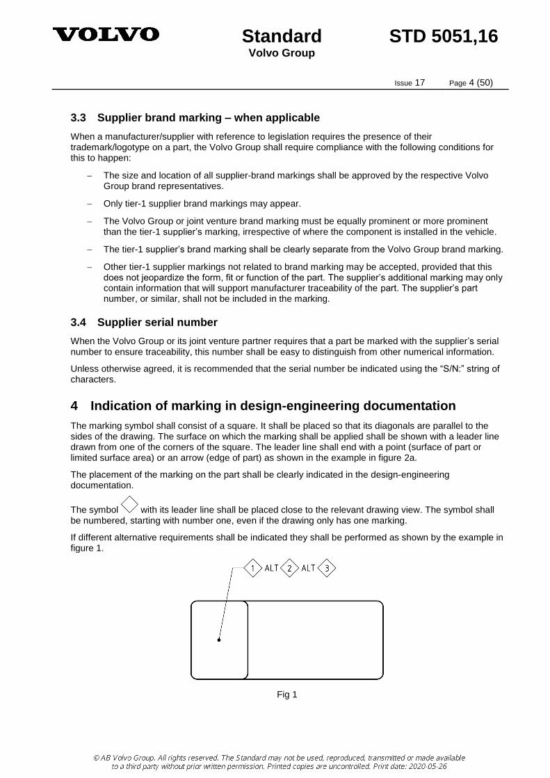
4 Indication of marking in design-engineering documentation
The marking symbol shall consist of a square. It shall be placed so that its diagonals are parallel to the sides of the drawing. The surface on which the marking shall be applied shall be shown with a leader line drawn from one of the corners of the square. The leader line shall end with a point (surface of part or limited surface area) or an arrow (edge of part) as shown in the example in figure 2a.
The placement of the marking on the part shall be clearly indicated in the design-engineering documentation.
The symbol with its leader line shall be placed close to the relevant drawing view. The symbol shall be numbered, starting with number one, even if the drawing only has one marking.
If different alternative requirements shall be indicated they shall be performed as shown by the example in figure 1.
Fig 1

Standard STD 5051,16 Volvo Group
Issue 17 Page 5 (50)
If several different markings as per this standard shall be indicated, or if there is a need to split a marking in different locations, they shall be considered separate marking requirements and thereby be indicated separately, as shown by the example in figure 2a.
If the marking area shall be limited, this must be indicated with a long-dashed, double-dotted, narrow line. Its dimension and placement shall be given in accordance with the example in figure 2a.
For indication of the opposite (hidden) surface, a dashed leader line is used as per figure 2b.
Fig. 2a Fig. 2b
The marking requirement as such shall be documented in the PDM system for the part concerned. If the PDM system lacks this functionality, the marking requirement shall be documented on the drawing or in a technote.
The indication shall follow the structure in figure 3.
Section Table MARKED ACCORDING TO STD 5051,16
MET 2.1.1 - 1G - HPS1 - A25
Brand marking size / Text height 8 5–13
Supplementary markings 7 3
Basic marking 6 2
Marking method 5 1
Fig. 3
If the marking text shall be read in a specific direction, an arrow showing the reading direction shall be indicated, see figure 2a.
Standard STD 5051,16 Volvo Group
Issue 17 Page 6 (50)
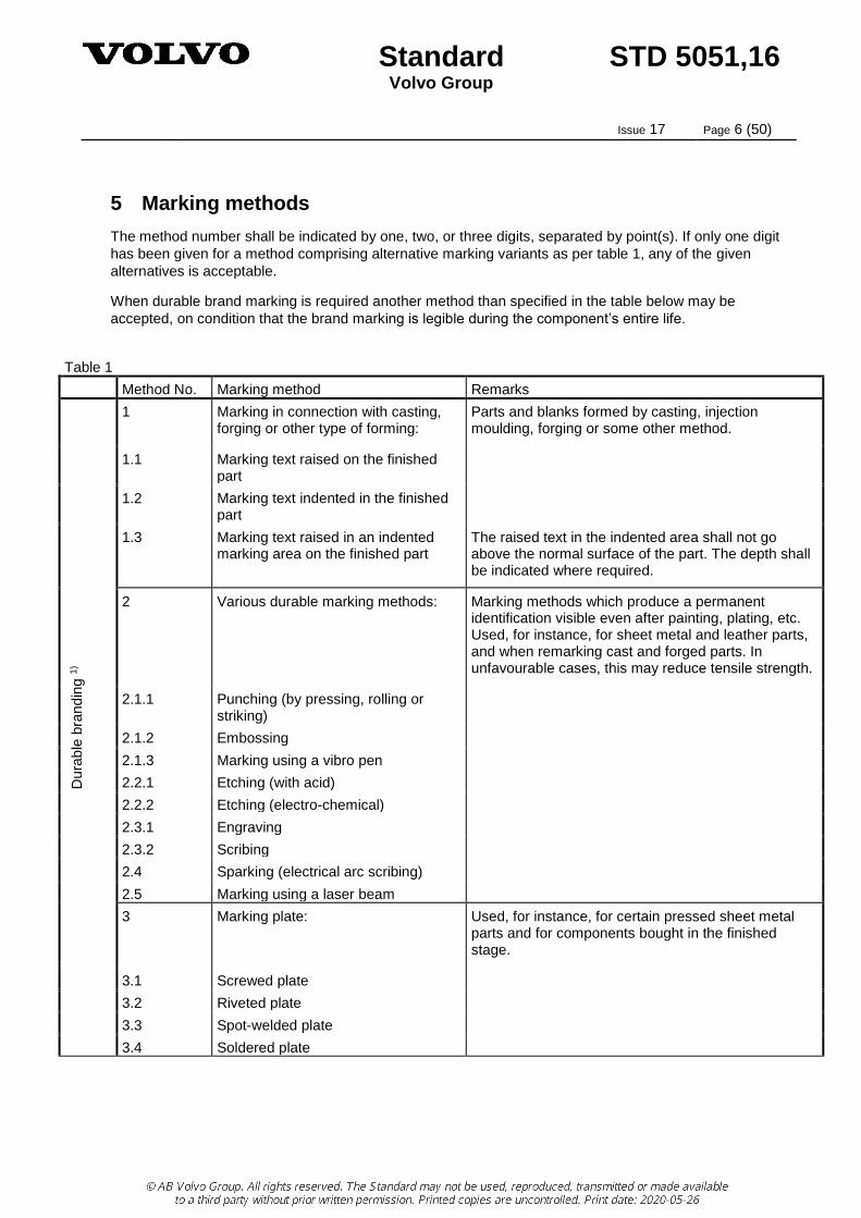
5 Marking methods
The method number shall be indicated by one, two, or three digits, separated by point(s). If only one digit
has been given for a method comprising alternative marking variants as per table 1, any of the given
alternatives is acceptable.
When durable brand marking is required another method than specified in the table below may be
accepted, on condition that the brand marking is legible during the component’s entire life.
Table 1
Method No. Marking method Remarks
Dura
ble
bra
nd
ing
1)
1 Marking in connection with casting, forging or other type of forming:
Parts and blanks formed by casting, injection moulding, forging or some other method.
1.1 Marking text raised on the finished part
1.2 Marking text indented in the finished part
1.3 Marking text raised in an indented marking area on the finished part
The raised text in the indented area shall not go above the normal surface of the part. The depth shall be indicated where required.
2 Various durable marking methods: Marking methods which produce a permanent identification visible even after painting, plating, etc. Used, for instance, for sheet metal and leather parts, and when remarking cast and forged parts. In unfavourable cases, this may reduce tensile strength.
2.1.1 Punching (by pressing, rolling or striking)
2.1.2 Embossing
2.1.3 Marking using a vibro pen
2.2.1 Etching (with acid)
2.2.2 Etching (electro-chemical)
2.3.1 Engraving
2.3.2 Scribing
2.4 Sparking (electrical arc scribing)
2.5 Marking using a laser beam
3 Marking plate: Used, for instance, for certain pressed sheet metal parts and for components bought in the finished stage.
3.1 Screwed plate
3.2 Riveted plate
3.3 Spot-welded plate
3.4 Soldered plate

Standard STD 5051,16 Volvo Group
Issue 17 Page 7 (50)
Table 1
Method No. Marking method Remarks
Non-d
ura
ble
bra
ndin
g 2
)
4 Adhesion: Non-durable marking method used, for instance, for plastics and rubber parts and for components bought in the finished stage.
4.1 Label (adhesive)
4.2 Decal (decalcomania)
4.3 Band (tape)
4.4 Long-life label (adhesive) This can be considered durable branding in some applications (refer to the branding guidelines)
5 Stamping, Stenciling or Painting Used, for instance, on mandrel vulcanized rubber parts as well as on parts made of metal, plastic, fibre, paper, leather and cork. Unless otherwise specified, the marking colour is at the suppliers’ discretion, but it shall contrast with the final colour of the furnished part. The logotype can be printed on the original material. May be carried out as screen print. Considered non-durable as it may become invisible after painting, plating, etc. Branding may not be painted over unless the branding is visible after painting and with due consideration to the part material and quality of the painting.
5.1 With dye
5.2 With ink This can be considered durable branding in some applications (refer to the branding guidelines)
5.3 With paint This can be considered durable branding in some applications (refer to the branding guidelines)
5.4 Paint pen Paint pen shall not be used if the logotype and/or branding is required. The application with a paint pen is usually free hand, and the text height should be selected accordingly.
Dura
ble
bra
nd
ing
1)
6
Marking on rubber:
6.1 Vulcanization Mandrel vulcanized rubber parts
6.2 Hot stamping Free vulcanized rubber hose
1) BDAT level 2 2) BDAT level 3
6 Basic markings
This section describes the basic marking designations used for text marking on parts. In addition to this, supplementary marking designations in accordance with section 7 can be used.
The general requirement is that the marking shall be kept together and structured as shown in section 8.1, figure 6. If lack of space makes this impractical, the marking shall be spread out and this shall be indicated on the drawing by using multiple marking symbols (see figure 2a in section 4).

Standard STD 5051,16 Volvo Group
Issue 17 Page 8 (50)
6.1 Volvo Group brand marking
The Volvo Group brand markings are legally protected. They are specially designed for each brand. A correct representation of Volvo Group brand markings helps maintain this protection and is thus an absolute requirement.
All Volvo Group brand markings have a fixed graphic form, and the distances between the various elements must never be changed. The brand markings may not occur in running text or be changed by the addition of text, pictures or symbols.
Unless otherwise stated, when a brand marking is reproduced by e.g. casting, punching, embossing, the letters shall be filled and evenly raised or lowered, depending on marking method, in relation to the surrounding surface.
6.2 Part number
The identity of the part (the part number) shall be given in the marking text.
The clearance all around the part number shall be equal to at least half the height of the marking.
6.3 Country of origin
Parts that require indication of the country of origin in the marking shall include the words “MADE IN”, followed by the actual name of the country of origin.
Unless otherwise agreed, the complete indication of the country of origin shall be performed in capital
letters.
The name of the country of origin shall correspond to the short name in English as stated in ISO 3166-1,
List one, first column.
No abbreviation or alpha-2 code, alpha-3 code or numeric code of the country name is permitted. For
example, USA shall be indicated as “UNITED STATES”.
The country of origin marking shall be performed on one line. However, if the marking space is limited the
marking may be performed on a maximum of two lines, where the words “MADE IN” are printed on the
first line and the actual country name is printed on the second line.
6.4 Special requirements for the United States
Special requirements apply to parts of foreign origin brought into the United States, even if no country of origin marking has been indicated in the basic marking as per table 2.
According to Section 304 of the Tariff Act of 1930, all imported parts must have country of origin marking,
see Code of Federal Regulations, Title 19 - Custom Duties, Part 134 - Country of Origin Marking.
Note: If you have questions or want clarification to ensure correct adherence to the marking standard
related to country of origin, please e-mail your request to:
[email protected] with "Country of Origin Marking Request" as the Subject.
6.5 Designations
Designations specifying country of origin without the mandatory prefix “MADE IN” shall not be used for
new design. These designations have been transferred to table B1 in Appendix B.
Other designations that shall not be used for new design have been transferred to table B1 in Appendix B.

Standard STD 5051,16 Volvo Group
Issue 17 Page 9 (50)
6.6 Free-text marking
Free-text marking indicated by the designation “0” refers to other marking information specified by the
Volvo Group than that specified using designations 1–50 in table 2.
In these cases, a specification of what information to include in the marking shall be given. This
information shall be placed within quotation-marks.
6.7 Supplementary marking
The designation “99” shall be used when supplementary marking only is applied without basic marking.
Table 2
Designation Marking information Example
0 Free-text marking (refers to other marking information than that specified by the other designations given in this table).
99 Only supplementary marking
1G The VOLVO brand mark 1) + part number + country of origin
12345678 MADE IN SWEDEN
2 The VOLVO brand mark 1) + part number
3G The VOLVO brand mark 1) + country of origin
4G Part number + country of origin
5 The VOLVO brand mark 1)
6 Part number 12345678
7G Country of origin MADE IN SWEDEN
8 Text: Made by XXXXX for YYYYY 2)
17G The UD TRUCKS brand mark 1) + part number + country of origin
12345678 MADE IN JAPAN
18 The UD TRUCKS brand mark 1) + part number
19G The UD TRUCKS brand mark 1) + country of origin
20 The UD TRUCKS brand mark 1)

Standard STD 5051,16 Volvo Group
Issue 17 Page 10 (50)
Table 2
Designation Marking information Example
23G The RENAULT TRUCKS brand mark 1) + part number + country of origin
12345678 MADE IN FRANCE
24 The RENAULT TRUCKS brand mark 1) + part number
25G The RENAULT TRUCKS brand mark 1) + country of origin
26 The RENAULT TRUCKS brand mark 1)
27G The EICHER brand mark 1) + part number + country of origin
12345678 MADE IN INDIA
28 The EICHER brand mark 1) + part number
29G The EICHER brand mark 1) + country of origin
30 The EICHER brand mark 1)
31G The MACK brand mark 1) + part number + country of origin
12345678 MADE IN UNITED STATES
32 The MACK brand mark 1) + part number
33G The MACK brand mark 1) + country of origin
34 The MACK brand mark 1)
35G The SDLG brand mark 1) + part number + country of origin
12345678 MADE IN CHINA
36 The SDLG brand mark 1) + part number

Standard STD 5051,16 Volvo Group
Issue 17 Page 11 (50)
Table 2
Designation Marking information Example
37G The SDLG brand mark 1) + country of origin
38 The SDLG brand mark 1)
39G The PREVOST brand mark 1) + part number + country of origin
12345678 MADE IN CANADA
40 The PREVOST brand mark 1) + part number
41G The PREVOST brand mark 1) + country of origin
42 The PREVOST brand mark 1)
43G The NOVA BUS brand mark 1) + part number + country of origin
12345678 MADE IN CANADA
44 The NOVA BUS brand mark 1) + part number
45G The NOVA BUS brand mark 1) + country of origin
46 The NOVA BUS brand mark 1)
47G The ARQUUS brand mark 1) + part number + country of origin
12345678 MADE IN FRANCE
48 The ARQUUS brand mark 1) + part number
49G The ARQUUS brand mark 1) + country of origin
50 The ARQUUS brand mark 1)
1) Note the different types and clear-zone requirements (see section 8). 2) XXXXX = Name or trademark of the supplier; YYYYY = Volvo Group entity

Standard STD 5051,16 Volvo Group
Issue 17 Page 12 (50)
7 Supplementary markings
Table 3
Designation Marking information Example of marking text
Remarks
E Batch number Number that relates the product with all other units of
the same product from the same production batch.
F Serial number S/N: 1234ABCD Number assigned to an entity for its lifetime
H Change condition/ version suffix
-1 -1 = part version 01 -2 = part version 02 etc. (acc. to the drawing or Part Version Report)
J Right-hand part RH Right Hand
K Left-hand part LH Left Hand
M Date of manufacture 10-015 Year-Day. The ordinal number of one day is represented by three digits. The first day of any year is
represented by 001 and subsequent days in ascending sequence.
N Blank number Blank 1234567
Number for blank may be specified in order to facilitate handling up to the stage of machining. Normally not indicated on the drawing.
P Supplier ID 12345 Max. 5 digits according to the series of the respective purchasing unit. The supplier's name (letters) may be used in exceptional cases (after approval by the Volvo Group entity concerned).
Q Tool number -12 Max. 2 digits. Normally not stated on the drawing but is generally required when one and the same part is manufactured at the same time in different tools or in different mould compartments in the same tool.
R Heat number 1234 A heat or a charge is a quantity of steel or any other metal which has been produced simultaneously in one melting furnace. The heat number may consist of digits, letters or a combination of digits and letters (if possible, maximum 4 characters).
S Date of manufacture If only designation S has been given for marking infor-mation, any of the alternatives S1, S2, S3 or S4 is accepted.
S1 Date of manufacture 10-04 Year-Month. The part will be marked, e.g., 10-04. For cast parts, this may be replaced by a date clock on an ejector plane. (See figures 3a, 4a.)
S2 Date of manufacture GA Year-Month. In encoded form acc. to table 4. The part will be marked, e.g., GA (2016/January).
S3 Date of manufacture (not ISO)
04-10 Month-Year. In those cases another form of date indication is required by national laws (e.g. USA). The part will be marked, e.g., 04-10. For cast parts, this may be replaced by a date clock on an ejector plane.

Standard STD 5051,16 Volvo Group
Issue 17 Page 13 (50)
Table 3
Designation Marking information Example of marking text
Remarks
S4 Date of manufacture 150101 YearMonthDay This indication is used when there is a need for detailed traceability and method U is not an option. Below are two examples of how this can be indicated:
YYMMDD, DDMMYY
- YY indicates the year in the current century (e.g. 2015 = 15)
- MM indicates the month with two digits (e.g. January = 01)
- DD indicates day of month
T Date of manufacture 10W03 YearWeek (with W in between and no spaces) W = short for Week. Calendar week is represented by two digits. The first calendar week of the year shall be
identified as 01 and subsequent weeks shall be numbered in ascending sequence.
U Date of manufacture 10W031 YearWeekDay (with W in between and no spaces) W = short for Week. Day of week is represented by one
digit. Monday shall be identified as day 1 of any calendar week, and subsequent days of the same week shall be numbered in ascending sequence to
Sunday (day 7).
V Date of manufacture (see figures 4a and 4b)
Date clock or date insert, alt. date field for cast or injection-moulded parts as per figures 4a and 4b (year and month to be indicated).
X Date of manufacture (see figures 5a and 5b)
Date clock or date insert, alt. date field for cast or injection-moulded parts as per figures 5a and 5b (year and month to be indicated).
Y Date of manufacture Date clock or date insert, alt. date field as per V or X but with other dimensions (dimensioned on drawing) (year and month to be indicated).
Z Compressed code 12R345 6 characters. Only used upon request from the manufacturing unit if there is insufficient space for complete marking. (Supplier code + RH or LH part + batch number, consecutive).

Standard STD 5051,16 Volvo Group
Issue 17 Page 14 (50)
Table 4 Examples of marking of date of manufacture in encoded form
Year Letter Year Letter Year Letter Month Letter
2015 F 2027 V 2039 9 January A
2016 G 2028 W 2040 A February B
2017 H 2029 X 2041 B March C
2018 J 2030 Y 2042 C April D
2019 K 2031 1 2043 D May E
2020 L 2032 2 2044 E June F
2021 M 2033 3 2045 F July G
2022 N 2034 4 2046 G August H
2023 P 2035 5 2047 H September J
2024 R 2036 6 2048 J October K
2025 S 2037 7 2049 K November L
2026 T 2038 8 2050 L December M
Figures 4a, 4b, 5a and 5b shall be regarded as explanatory figures, and other designs are therefore
accepted (shall be approved by the Volvo Group entity concerned). Tolerance zone 2 mm.
The date fields as per figures 4b and 5b shall comprise a ten-year period, starting with the year the part was first manufactured in the top left-hand square.
Date clock or date insert V (2013 January indicated) Date field V (new part in 2011 June, last date of manufacture 2012 March indicated)
Fig. 4a Fig. 4b
Date clock or date insert X (2013 February indicated) Date field X (new part in 2011 August, last date of manufacture 2012 March indicated)
Fig. 5a Fig. 5b

Standard STD 5051,16 Volvo Group
Issue 17 Page 15 (50)
8 Brand marking and text requirements
The different brand markings can be downloaded, in various file formats, from Brand Center on the Volvo
Group Intranet.
Suppliers can obtain the brand markings in a suitable file format by requesting it from their Volvo Group
contact.
If the marking contains a brand mark, the specified size in the designation refers to the brand mark. When
there are different marking alternatives for a brand, the required marking shall be indicated by a prefix as
per the relevant table.
Whenever a brand mark has a wordmark or a text element, this shall act as a guide for the text height of
the other information. The text height (H1 and H2) of the other information shall be smaller than the height
(H) of the brand marking. See tables for the respective brands.
Requirements concerning text height (H1 and H2, respectively) can be found in the table for each brand.
For definition of text heights for different information, see figure 6 in section 8.1 Relative position of text on
marked part.
Parts exposed to dirt, underseal or similar shall have a minimum text height of 4 mm for legibility reasons.
Normally, the combination 6/4 for H1/ H2 should be used for such parts.
Note: Should this combination not be possible due to lack of space, a text height of 4 mm shall be
specified for all text. This must, however, be specified for each marking information, i.e.
Identification data, manufacturing data and country of origin.
Standard STD 5051,16 Volvo Group
Issue 17 Page 16 (50)
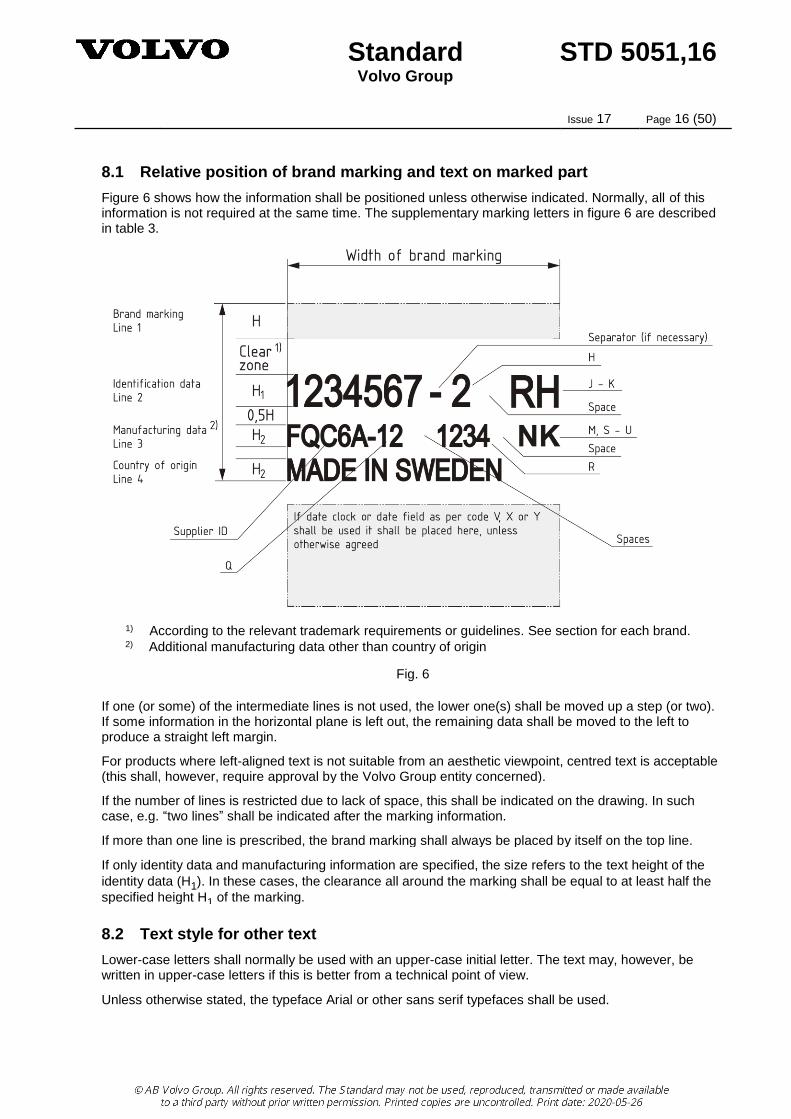
8.1 Relative position of brand marking and text on marked part
Figure 6 shows how the information shall be positioned unless otherwise indicated. Normally, all of this information is not required at the same time. The supplementary marking letters in figure 6 are described in table 3.
1) According to the relevant trademark requirements or guidelines. See section for each brand. 2) Additional manufacturing data other than country of origin
Fig. 6
If one (or some) of the intermediate lines is not used, the lower one(s) shall be moved up a step (or two). If some information in the horizontal plane is left out, the remaining data shall be moved to the left to produce a straight left margin.
For products where left-aligned text is not suitable from an aesthetic viewpoint, centred text is acceptable (this shall, however, require approval by the Volvo Group entity concerned).
If the number of lines is restricted due to lack of space, this shall be indicated on the drawing. In such case, e.g. “two lines” shall be indicated after the marking information.
If more than one line is prescribed, the brand marking shall always be placed by itself on the top line.
If only identity data and manufacturing information are specified, the size refers to the text height of the
identity data (H1). In these cases, the clearance all around the marking shall be equal to at least half the
specified height H1 of the marking.
8.2 Text style for other text
Lower-case letters shall normally be used with an upper-case initial letter. The text may, however, be written in upper-case letters if this is better from a technical point of view.
Unless otherwise stated, the typeface Arial or other sans serif typefaces shall be used.

Standard STD 5051,16 Volvo Group
Issue 17 Page 17 (50)
8.3 Colours
For a correct representation of the Volvo Group corporate colours, the information provided at Brand
Center on the Volvo Group Intranet shall be used.
Suppliers can obtain the information about corporate colours from their Volvo Group contact.
When printed, the VOLVO or the VOLVO PENTA wordmark shall always be represented in one of its
corporate colours.
When printed, the PREVOST logotype must always be represented in black.
When printed, the NOVA BUS logotype must always be represented in black.
If no colour requirement has been specified on the drawing, the marking text shall be applied “colourless”
(in the case of marking methods 1, 2, or 6).
If the drawing specifies one single colour (black or white), this refers to the colour of the text and the
surrounding surface is “colourless” (= substrate colour).
In the case of marking method 5 (stamping, stencilling or painting), and if no colour has been specified,
the marking shall be made black or white and shall contrast with the colour of the substrate.
Unless otherwise stated, the colour requirement for brand marking also applies to the marking text.
8.4 VOLVO and VOLVO PENTA
8.4.1 Brand mark size and clear zone
Sizes shall be chosen from table 5.
Note: Only the sizes specified in table 5 are allowed.
The minimum width of the VOLVO wordmark shall be 12,5 mm, see figure 7a.
The minimum width of the VOLVO PENTA wordmark on two lines shall be 13 mm, see figure 7b.
Fig. 7a VOLVO wordmark Fig. 7b VOLVO PENTA wordmark
When marking materials that, for some reason, do not permit the use of filled letters (e.g. hard materials), the letters may be produced with contour lines. See figures 8a and 8b. A suitable thickness for the contour lines is 1/100 of the length/width of the logotype. Contour lines may not be used in any other context.
Fig. 8a VOLVO wordmark contour Fig. 8b VOLVO PENTA wordmark contour

Standard STD 5051,16 Volvo Group
Issue 17 Page 18 (50)
The pre-determined clear zone around the VOLVO or the VOLVO PENTA wordmark shall be at least
equal to the height (X) of the VOLVO wordmark. See figures 9a and 9b.
Fig. 9a VOLVO wordmark clear zone Fig. 9b VOLVO PENTA wordmark clear zone
Note: In case of inadequate marking space, the clear zone may be equal to half the height of the
VOLVO wordmark.
The single-line VOLVO PENTA branding defined below may, after approval by the product design
department, be used if the available space is unsuitable for dual-line branding.
The minimum width of the VOLVO PENTA single-line wordmark shall be 27 mm, see figure 10.
Fig. 10 VOLVO PENTA single-line wordmark
The pre-determined clear zone around the VOLVO PENTA single-line wordmark shall be at least equal to
the height (X) of the VOLVO wordmark. See figure 10.
Fig. 11 VOLVO PENTA single-line wordmark clear zone

Standard STD 5051,16 Volvo Group
Issue 17 Page 19 (50)
8.4.2 Text height
The relationship between the text height [H] and the width [W] of each brand mark is given below:
VOLVO wordmark
H = 0,13 × W
VOLVO PENTA wordmark (two lines)
H = 0,12 × W
VOLVO PENTA wordmark (one line)
H = 0,06 × W
Table 5
The VOLVO brand mark Text height H1
(line 2)
Text height H2
(lines 3 and 4)
VOLVO
wordmark
VOLVO
PENTA
wordmark
(two lines)
VOLVO
PENTA
wordmark
(one line)
Height
approx.
[mm]
Width
[mm]
Width
[mm]
Width
[mm]
Tol
[mm]
Nominal
[mm]
Tol
[mm]
Nominal
[mm]
Tol
[mm]
1,2 0,1 0,8 0,1
1,6 A12,5 B13 C27 0,6 1,6 1
2 A15 B17 C33 0,8 2 1,2
2,6 A20 B22 C43 1 2,5 1,6
3,2 A25 B27 C54 1,2 3 0,2 2
3,9 A30 B33 C65 1,5 3,5 2,5
5,2 A40 B42 C86 2 5 3 0,2
6,5 A50 B53 C108 2,5 6 0,4 4
7,8 A60 B65 C130 3 7,5 5
10,4 A80 B87 C173 4 10 0,5 6 0,4
13 A100 B108 C217 5 12,5 8
16 A125 B133 C267 6 16 0,8 10 0,6
21 A160 B170 C346 8 20 12

Standard STD 5051,16 Volvo Group
Issue 17 Page 20 (50)
8.5 UD TRUCKS
The UD Trucks brand mark is comprised of the brand symbol and the wordmark.
On parts where a UD Trucks brand marking cannot be executed at its minimum size in accordance with
this standard, the symbol by itself can be permitted (see figure 16). The choice of execution should be
based on the available space on each specific part.
Vertical use of the brand mark shall be given precedence.
Use of the UD Trucks brand mark shall be made in accordance with the following preference:
1. UD brand mark in vertical format, see figure 12
2. UD brand mark in horizontal format, see figure 14
3. UD logotype, see figure 16
4. UD symbol, see figure 17
For questions regarding the use of the UD Trucks brand mark, please contact Kenneth Hagas
8.5.1 Application
Use of the UD TRUCKS brand mark must comply with the latest issue of the UD Trucks brand guideline
A_Basic elements 6.1.
This must be followed in order to reproduce the brand mark accurately.
8.5.2 Brand mark size and clear zone
Sizes shall be chosen from table 6.
Note: Only the sizes specified in table 6 are allowed.
The minimum dimension of the UD TRUCKS brand mark in vertical format shall be in accordance with
figure 12.
Fig. 12 UD TRUCKS brand mark, vertical format

Standard STD 5051,16 Volvo Group
Issue 17 Page 21 (50)
The relative size of each brand mark element and the established minimum clear zone around the brand
mark shall be in accordance with figure 13.
Fig. 13 UD TRUCKS brand mark, vertical format, relative size and clear zone
The minimum dimension of the UD Trucks brand mark in horizontal format shall be in accordance with
figure 14.
Fig. 14 UD TRUCKS brand mark, horizontal format

Standard STD 5051,16 Volvo Group
Issue 17 Page 22 (50)
The relative size of each brand mark element and the established minimum clear zone around the brand
mark shall be in accordance with figure 15.
Fig. 15 UD TRUCKS brand mark, horizontal format, relative size and clear zone
The minimum dimension of the UD TRUCK wordmark shall be in accordance with figure 16.
Fig. 16 UD TRUCKS logotype
The minimum dimension of the UD TRUCKS symbol shall be in accordance with figure 17.
Fig. 17 UD TRUCKS symbol

Standard STD 5051,16 Volvo Group
Issue 17 Page 23 (50)
8.5.3 Text height
The relationship between the text height [H] and the width [W] of each brand mark is given below:
UD TRUCKS vertical brand mark (Type A)
H = 0,11 × W
UD TRUCKS horizontal brand mark (Type B)
H = 0,08 × W
UD TRUCKS brand logotype (Type C)
H = 0,11 × W
UD TRUCKS brand symbol (Type D)
H = 0,29 × W
All dimensions of the UD brand mark are based on the brand symbol height that is described in the UD Trucks Identity Guideline.
Table 6
The UD TRUCKS brand marks Text height H1
(line 2)
Text height H2
(lines 3 and 4)
Type A
Size
(Width)
Type B
Size
(Width)
Type C
Size
(Width)
Type D
Size
(Width)
Nominal
[mm]
Tol
[mm]
Nominal
[mm]
Tol
[mm]
A13 C13 1,2 0,1 0,8 0,1
A18 C18 2 1,2
A25 B25 C25 2,5 1,6
A30 B43 C30 3 0,2 2
A35 B50 C35 D6 4 2,5
A45 B65 C45 D7 5 3 0,2
A55 B75 C55 D8 6 0,4 4
A75 B100 C75 D11 8 5
A90 B125 C90 D13 10 0,5 6 0,4
A115 B155 C115 D17 12,5 8
A145 B200 C145 D22 16 0,8 10 0,6
A185 B250 C185 D30 20 12

Standard STD 5051,16 Volvo Group
Issue 17 Page 24 (50)
8.6 SDLG
For questions regarding the use of the SDLG brand mark, please contact:
8.6.1 Brand mark size and clear zone
Sizes shall be chosen from table 7.
Note: Only the sizes specified in table 7 are allowed.
The minimum size of the SDLG logo shall be 10 mm. See figure 18.
Fig. 18 SDLG brand mark
In accordance with the SDLG CORPORATE IDENTITY MANUAL, the pre-determined clear zone around
the logotype shall be at least equal to half the width of the logotype. See figure 19.
Fig. 19 SDLG brand mark clear zone

Standard STD 5051,16 Volvo Group
Issue 17 Page 25 (50)
8.6.2 Text height
The relationship between the text height [H] and the width [W] of each brand mark is given below:
SDLG logotype
H = 0,19 × W
Table 7
The SDLG brand mark (Width) [mm]
Text height H1
(line 2)
Text height H2
(lines 3 and 4)
Nominal
[mm]
Tol
[mm]
Nominal
[mm]
Tol
[mm]
1,2 0,1 0,8 0,1
10 2 1,2
15 2,5 1,6
20 3 0,2 2
25 4 2,5
30 5 3 0,2
35 6 0,4 4
45 8 5
55 10 0,5 6 0,4
65 12,5 8
85 16 0,8 10 0,6
105 20 12

Standard STD 5051,16 Volvo Group
Issue 17 Page 26 (50)
8.7 RENAULT TRUCKS
The font to be used is DIN Pro Medium.
Sizes shall be chosen from table 8.
Note: Only the sizes specified in table 8 are allowed.
8.7.1 Principle of construction and dimensions of standardized markings
The construction and dimensions of the brand mark shall comply with section 8.7.2. However, if this is
technically impossible or if the marking area is too small for the RENAULT TRUCKS brand mark on two
lines, the marking may be performed in accordance with section 8.7.3. or section 8.7.4, where the
wordmark defined in section 8.7.2 is to be preferred.
8.7.2 RENAULT TRUCKS on two lines
The minimum width of the RENAULT TRUCKS two-line brand marking shall be 16 mm, see figure 20.
Fig. 20 RENAULT TRUCKS wordmark on two lines
The established minimum clear zone around the logotype shall be equal to the height of the letter “R”, see
figure 21.
Fig. 21 RENAULT TRUCKS wordmark on two lines, clear zone
8.7.3 RENAULT TRUCKS on one line
If the available marking space is too small to use the branding defined in section 8.7.2, the single-line
RENAULT TRUCKS branding defined below may be used after approval by the design-engineering
department.
The minimum width of the RENAULT TRUCKS single-line brand marking shall be 30 mm, see figure 22.
Fig. 22 RENAULT TRUCKS single-line wordmark

Standard STD 5051,16 Volvo Group
Issue 17 Page 27 (50)
The established minimum clear zone around the logotype shall be equal to the height of the letter “R”, see
figure 23.
Fig. 23 RENAULT TRUCKS single-line wordmark, clear zone
8.7.4 RENAULT TRUCKS diamond
A RENAULT TRUCKS diamond, as defined below, may, with product design department approval, be used when the space available is too small to use the RENAULT TRUCKS branding defined in sections 8.7.2 and 8.7.3.
Minimum dimension C12 (12 mm) according to table 8:
Fig. 24 RENAULT TRUCKS diamond
The minimum clear zone for the RENAULT TRUCKS diamond shall be H1 according to table 8.
Fig. 25 RENAULT TRUCKS diamond, clear zone

Standard STD 5051,16 Volvo Group
Issue 17 Page 28 (50)
8.7.5 Text height
The relationship between the text height [H] and the width [W] of each brand mark is given below:
RENAULT TRUCKS wordmark (two lines)
H = 0,17 × W
RENAULT TRUCKS wordmark (one line)
H = 0,09 × W
RENAULT TRUCKS diamond
Table 8
The RENAULT TRUCKS logotype Text height H1
(line 2)
Text height H2
(lines 3 and 4) RENAULT TRUCKS
(two lines)
RENAULT TRUCKS
(one line)
RENAULT TRUCKS
diamond
Length
[mm]
Tol
[mm]
Length
[mm]
Tol
[mm]
Height
[mm]
Tol
[mm]
Nominal
[mm]
Tol
[mm]
Nominal
[mm]
Tol
[mm]
C12 0,6 1,2 0,1 0,8 0,1
C14 0,6 1,6 1
A16 0,8 B30 1,5 C16 0,8 2 1,2
A20 1 B40 2 C20 1 2,5 1,6
A25 1,2 B50 2,5 3 0,2 2
A30 1,5 4 2,5
A40 2 5 3 0,2
A50 2,5 6 0,4 4
A60 3 8 5
A80 4 10 0,5 6 0,4
A100 5 12,5 8
A125 6 16 0,8 10 0,6
A160 8 20 12

Standard STD 5051,16 Volvo Group
Issue 17 Page 29 (50)
8.8 PREVOST
8.8.1 Brand mark size and clear zone
Sizes shall be chosen from table 9.
Note: Only the sizes specified in table 9 are allowed.
The minimum size of the PREVOST wordmark shall be 25 mm. See figure 26.
Fig. 26 PREVOST wordmark
The clear zone is equal to 1,5 times the height of the Prevost logotype all around it. This dimension can
also be calculated using the rotated ’P’ of the Prevost logotype, see figure 27.
Fig. 27 PREVOST wordmark clear zone
8.8.2 Text height
The relationship between the text height [H] and the width [W] of the brand mark is given below:
PREVOST wordmark
H = 0,08 × W
Values marked in bold italic shall be preferred.
Table 9
The PREVOST wordmark Text height H1
(line 2)
Text height H2
(lines 3 and 4)
Width
approx.
[mm]
Length
Nom (12,8xH)
[mm]
Tol
[mm]
Nominal
[mm]
Tol
[mm]
Nominal
[mm]
Tol
[mm]
1,95 25 1,2 2 0,1 1,2 0,1
2,4 31 1,5 2,5 1,6
3,1 40 2 3 0,2 2
3,9 50 2,5 4 2,5
4,9 63 3 5 3 0,2
6,25 80 4 6 0,4 4
7,9 101 5 8 5
9,8 125 6 10 0,5 6 0,4
12,5 160 8 12,5 8
Standard STD 5051,16 Volvo Group
Issue 17 Page 30 (50)
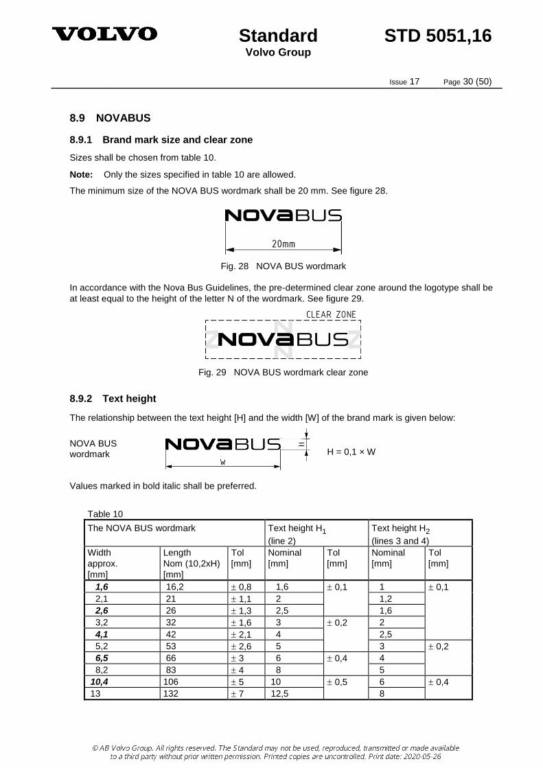
8.9 NOVABUS
8.9.1 Brand mark size and clear zone
Sizes shall be chosen from table 10.
Note: Only the sizes specified in table 10 are allowed.
The minimum size of the NOVA BUS wordmark shall be 20 mm. See figure 28.
Fig. 28 NOVA BUS wordmark
In accordance with the Nova Bus Guidelines, the pre-determined clear zone around the logotype shall be
at least equal to the height of the letter N of the wordmark. See figure 29.
Fig. 29 NOVA BUS wordmark clear zone
8.9.2 Text height
The relationship between the text height [H] and the width [W] of the brand mark is given below:
NOVA BUS wordmark
H = 0,1 × W
Values marked in bold italic shall be preferred.
Table 10
The NOVA BUS wordmark Text height H1
(line 2)
Text height H2
(lines 3 and 4)
Width
approx.
[mm]
Length
Nom (10,2xH)
[mm]
Tol
[mm]
Nominal
[mm]
Tol
[mm]
Nominal
[mm]
Tol
[mm]
1,6 16,2 0,8 1,6 0,1 1 0,1
2,1 21 1,1 2 1,2
2,6 26 1,3 2,5 1,6
3,2 32 1,6 3 0,2 2
4,1 42 2,1 4 2,5
5,2 53 2,6 5 3 0,2
6,5 66 3 6 0,4 4
8,2 83 4 8 5
10,4 106 5 10 0,5 6 0,4
13 132 7 12,5 8

Standard STD 5051,16 Volvo Group
Issue 17 Page 31 (50)
8.10 MACK
8.10.1 The MACK wordmark
Parts that require branding that is visible during normal operation of the truck or parts that require durable
branding shall be marked with the MACK wordmark, see figure 30.
Follow the defined clear space and minimum size rules to ensure scaling and legibility of the mark.
To learn more about the application of Mack branding and to download the assets, please refer to the
Mack Aftermarket Guidelines on the Mack Brand Center on Violin (for internal use) or
https://media.macktrucks.com/ (for external suppliers).
For questions regarding the use of the MACK wordmark and PURE MACK, please contact Andrea
McLaughlin [email protected].
All parts branding and durable aftermarket marking proposals should be presented to Mack’s Design
Director for final approval before production.
8.10.2 Application
The minimum dimension of the MACK wordmark shall be 12,7 mm, see figure 30.
Sizes shall be chosen from table 11.
Note: Only the sizes specified in table 11 are allowed.
Fig 30 MACK wordmark
The established minimum clear zone around the MACK wordmark shall be equal to the width of the letter
M in the wordmark, see figure 31.
Fig 31 MACK wordmark clear zones

Standard STD 5051,16 Volvo Group
Issue 17 Page 32 (50)
8.10.3 The PURE MACK seal
Parts that require marking on the B-side (reverse side/back side/inside), meaning that the marking is not
visible during normal operation of the truck or after installation on the truck, shall be branded with the
PURE MACK seal or its secondary applications based on legibility and product texture, see figures 32,
33a and 33b, respectively.
The PURE MACK seal or its secondary applications shall be used in accordance with the following
preference:
1. Type B – The PURE MACK seal, see figure 32
2. Type C – The PURE MACK wordmark on two lines, see figure 33a
3. Type D – The PURE MACK wordmark on a single line, see figure 33b
8.10.4 Application
The minimum dimension of the PURE MACK seal shall be 19 mm, see figure 32.
Sizes shall be chosen from table 11.
Note: Only the sizes specified in table 11 are allowed.
Fig. 32 Pure Mack seal minimum dimension
On parts where the PURE MACK seal cannot be executed at its minimum size in accordance with this
standard, either of these PURE MACK double-line or single-line executions is permitted, see figures 33a
and 33b. The double-line or single-line execution shall be chosen based on the available space on each
specific part.
Fig. 33a Minimum dimension of double line Fig. 33b Minimum dimension of single line
The use of either of these executions shall be indicated with the relevant prefix in table 11.

Standard STD 5051,16 Volvo Group
Issue 17 Page 33 (50)
The established minimum clear zone around the PURE MACK seal shall be equal to half the width of the
seal, see figure 34.
Fig. 34 PURE MACK seal with clear zone
For the double-line or single-line brand marking, the minimum clear zone shall be equal to the width of the letter “M”, see figures 35a and 35b.
Fig. 35a Double-line with clear zone Fig. 35b Single-line with clear zone
Manufactured and purchased assemblies shall be identified by the assembly number; component parts
shall not be identified. Items similar to engines, transmissions, differential carriers, and axles are an
exception. See section 6 Basic Marking and the examples given in Appendix A1.
In general, the PURE MACK seal trademark shall not be illustrated on the part drawing.
Below is an example of a part with both a brand marking that is visible to the customer (figure 36a) and a
required durable B-side (reverse side/back side/inside) marking (figure 36b).
FRONT
BACK
Fig 36a Fig 36b

Standard STD 5051,16 Volvo Group
Issue 17 Page 34 (50)
8.10.5 Text height
The relationship between the text height [H] and the width [W] or diameter [D] of each brand mark is given below:
MACK wordmark
H = 0,1 × W
PURE MACK seal
H = 0,15 × øD
PURE MACK wordmark (two lines)
H = 0,24 × W
PURE MACK wordmark (one line)
H = 0,12 × W
Table 11
MACK
wordmark
PURE MACK Text height H1
(line 2)
Text height H2
(lines 3 and 4)
seal wordmark
double line
wordmark
single line
Width
[mm]
Diameter
[mm]
Width
[mm]
Width
[mm]
Nominal
[mm]
Tol
[mm]
Nominal
[mm]
Tol
[mm]
A12,7 1,2 0,1 1 0,1
A16 1,6 1
A19 D19 2 1,2
A22 2 1,2
A25 B19 C13 D22 2,5 1,6
A30 B22 C14,5 D27 3 0,2 2
A40 B28 C19 D38 4 2,5
A50 B36 C24 D49 5 3 0,2
A60 B43 C29 D55 6 0,4 4
A80 B55 C37 D72 8 5
A100 B68 C46 D90 10 0,5 6 0,4
A125 B83 C56 D111 12,5 8

Standard STD 5051,16 Volvo Group
Issue 17 Page 35 (50)
8.11 EICHER
8.11.1 Brand mark requirements
The EICHER trademarks shown on drawing 21692507 shall be used and applied on all new and changed
components/parts released by Engineering in accordance with the procedures and requirements outlined
in this standard.
The use of the EICHER logotype must comply with the latest issue of the EICHER NEW LOGO BASIC
GUIDELINES. Contact the EICHER Brand Management Team for more information:
EICHER Brand Team
VE Commercial Vehicles Ltd.
Eicher Trucks and Buses
# 96, Sector 32, Gurgaon-122 001
Haryana, India
The EICHER brand mark shall be used in accordance with the following preferences:
1. Type D (stacked version consisting of the horsehead symbol and the wordmark), see figure 37a
2. Type C (side-by-side version consisting of the horsehead symbol and the wordmark), see figure 37b
3. Type B (horsehead symbol only), see figure 37c
4. Type A (wordmark only), see figure 37d
Types A and B shall only be used in case of insufficient space on the part.
The different types of EICHER brand markings are indicated by using the designations found in table 12.
8.11.2 Brand mark size and clear zone
Sizes shall be chosen from table 12.
Note: Only the sizes specified in table 12 are allowed.
The minimum width of the EICHER brand mark, type D, shall be 20 mm.
Fig. 37a EICHER stacked logotype – Type D

Standard STD 5051,16 Volvo Group
Issue 17 Page 36 (50)
The minimum width of the EICHER brand mark, type C, shall be 50 mm.
Fig. 37b EICHER side-by-side logotype – Type C
Fig. 37c EICHER horsehead symbol – Type B
Fig. 37d EICHER wordmark – Type A
The clear zone around the logotype shall be at least equal to the height of the letter E in the wordmark.
See figure 38 for example.
Fig. 38 EICHER example of clear zones

Standard STD 5051,16 Volvo Group
Issue 17 Page 37 (50)
8.11.3 Text height
The relationship between the text height [H] and the width [W] of each brand mark is given below:
EICHER wordmark (Type A)
H = 0,19 × W
EICHER symbol 1) (Type B)
H = 0,38 × W
EICHER horizontal logotype (Type C)
H = 0,12 × W
EICHER vertical logotype (Type D)
H = 0,19 × W
1) In cases where the brand mark does not contain a wordmark or text, the height H = H1.
Table 12
The EICHER brand mark Text height H1
(line 2)
Text height H2
(lines 3 and 4)
Type A
Size
Type B
Size
Type C
Size
Type D
Size
Nominal
[mm]
Tol
[mm]
Nominal
[mm]
Tol
[mm]
A10 B10 C10 D10 1,2 0,1 0,8 0,1
A12,5 B12,5 C12,5 D12,5 1,6 1
A15 B15 C15 D15 2 1,2
A20 B20 C20 D20 2,5 1,6
A25 B25 C25 D25 3 0,2 2
A30 B30 C30 D30 4 2,5
A40 B40 C40 D40 5 3 0,2
A50 B50 C50 D50 6 0,4 4
A65 B65 C65 D65 8 5
A80 B80 C80 D80 10 0,5 6 0,4
A100 B100 C100 D100 12,5 8
A125 B125 C125 D125 16 0,8 10 0,6
A135 B135 C135 D135 18 11
A145 B145 C145 D145 20 12
A200 B200 C200 D200 22 1,0 13 0,8
Standard STD 5051,16 Volvo Group
Issue 17 Page 38 (50)
8.12 ARQUUS
8.12.1 Brand mark requirements
The ARQUUS brand marks shown on drawing 23419628 shall be used and applied on all new and
changed components/parts released by Engineering in accordance with the procedures and requirements
outlined in this standard.
The use of the logotype must comply with the latest issue of Arquus Visual Language. Contact the
ARQUUS Brand Management Team for more information:
The ARQUUS brand mark shall be used in accordance with the following preference:
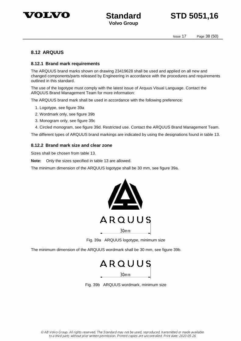
1. Logotype, see figure 39a
2. Wordmark only, see figure 39b
3. Monogram only, see figure 39c
4. Circled monogram, see figure 39d. Restricted use. Contact the ARQUUS Brand Management Team.
The different types of ARQUUS brand markings are indicated by using the designations found in table 13.
8.12.2 Brand mark size and clear zone
Sizes shall be chosen from table 13.
Note: Only the sizes specified in table 13 are allowed.
The minimum dimension of the ARQUUS logotype shall be 30 mm, see figure 39a.
Fig. 39a ARQUUS logotype, minimum size
The minimum dimension of the ARQUUS wordmark shall be 30 mm, see figure 39b.
Fig. 39b ARQUUS wordmark, minimum size

Standard STD 5051,16 Volvo Group
Issue 17 Page 39 (50)
The minimum dimension of the ARQUUS monogram shall be 20 mm, see figure 39c.
Fig. 39c ARQUUS monogram, minimum size
Use of the ARQUUS circled monogram, see figure 39d, is restricted. Contact the ARQUUS Brand
Management Team for further information about minimum dimensions and clear zones.
Fig. 39d ARQUUS circled monogram
The clear zone around the ARQUUS brand marking shall be at least equal to the size of the triangle in the
centre of the monogram. See figures 40a, 40b and 40c for examples.
Fig. 40a Example of clear zone around the ARQUUS logotype

Standard STD 5051,16 Volvo Group
Issue 17 Page 40 (50)
Fig. 40b Example of clear zone around the ARQUUS wordmark
Fig. 40c Example of clear zone around the ARQUUS monogram

Standard STD 5051,16 Volvo Group
Issue 17 Page 41 (50)
8.12.3 Text height
The relationship between the text height [H] and the width [W] of each brand mark is given below:
ARQUUS logotype
H = 0,13 × W
ARQUUS wordmark
H = 0,13 × W
ARQUUS monogram 1)
H = 0,19 × W
ARQUUS circled monogram 1)
H = 0,15 × W
1) In cases where the brand mark does not contain a wordmark or text, the height H = H1.
Table 13
The ARQUUS brand mark Text height H1
(line 2)
Text height H2
(lines 3 and 4)
ARQUUS
logotype
ARQUUS
wordmark
ARQUUS
monogram
ARQUUS
circled
monogram
Nominal
[mm]
Tol
[mm]
Nominal
[mm]
Tol
[mm]
Width
[mm]
Width
[mm]
Width
[mm]
Width
[mm]
Nominal
[mm]
Tol
[mm]
Nominal
[mm]
Tol
[mm]
1,2 0,1 0,8 0,1
1,6 1
A20 B20 C14 D17 2 1,2
A25 B25 C17 D21 2,5 1,6
A30 B30 C20 D25 3 0,2 2
A35 B35 C25 D31 4 2,5
A40 B40 C30 D37 5 3 0,2
A50 B50 C40 D50 6 0,4 4
A60 B60 C50 D62 7 5
A70 B70 C60 D75 8 6 0,4
A80 B80 C70 D87 10 0,5 6
A100 B100 C90 D112 12,5 8

Standard STD 5051,16 Volvo Group
Issue 17 Page 42 (50)
9 Associated standards
STD 920-0001 Representation of dates and times
STD 103-0002 Generic identification and marking of plastics products
STD 103-0010 Marking of aluminium parts
STD 103-0026 Marking of magnesium parts
STD 103-0013 Parts marking with bar codes and 2D symbologies
STD 103-0020 Marking on filters
STD 5052,21 Colour identification marking on rubber parts
ISO 3166-1 Codes for the representation of names of countries and their subdivisions
DIN 1451 Serifenlose Linear-Antigua

Standard STD 5051,16 Volvo Group
Issue 17 Page 43 (50)
Appendix A Marking examples
As an aid in the application of this standard, the following marking examples are given.
Example 1
For parts with common design-engineering documentation (e.g. multi-part drawings) but different
trademarks, this shall be indicated in accordance with the following example:
1) For part number 12345671:
MARKED ACCORDING TO STD 5051,16
MET 1.1 – 1G – A50
2) For part number 12345672:
MARKED ACCORDING TO STD 5051,16
MET 1.1 – 23G – A50
Example 2
MARKED ACCORDING TO STD 5051,16
MET 1.1 – 1G – P – A30
MARKED WITH PART NUMBER 12345678
Means: Marking method/Marking text raised – Basic marking/The VOLVO brand mark + part
number + country of origin – Additional markings/P = Supplier ID – Logotype size/A30 (indicates
VOLVO wordmark). For other text heights, see table 5.
It also illustrates marking with a part number that differs from the one that applies to the part in question,
for instance the assembly number.
Example 3
MARKED ACCORDING TO STD 5051,16
MET 1.1 – 0 – 6
ABCD 12345678
Means: Marking method/Marking text raised on the finished part – Free-text marking – Text height
(mm)/6
ABCD 12345678 = Free-text marking

Standard STD 5051,16 Volvo Group
Issue 17 Page 44 (50)
Example 4
MARKED ACCORDING TO STD
5051,16
MET 1.1 – 2 – A30
MARKED ACCORDING TO STD
5051,16
MET 1.1 – 7G – 3,5
The example above illustrates how to indicate that the marking shall be spread out on the part.
Means: Marking method/Marking text raised – Basic marking/The VOLVO brand mark +
part number – Logotype size/A30 (indicates VOLVO wordmark). For other text heights, see
table 5.
Means: Marking method/Marking text raised – Basic marking/Country of origin –
Logotype size/3,5 (text height smaller than VOLVO wordmark A30, see table 5)
Example 5
MARKED ACCORDING TO STD 5051,16
MET 1.1 – 99 – KV – 6
MET 1.1 – 99 – JV – 6
Means: Marking method/Marking test raised – Basic marking/No basic marking – Additional markings/
K = LH design, J = RH design (symmetric-opposite), V = date of manufacture – Text height (mm)/6.
Example 6
MARKED ACCORDING TO STD 5051,16
MET 2.2.1/MET 3.2 – 2 – JPS2 – A50
Means: Marking method/Etching (with acid)/riveted plate – Basic marking/The VOLVO brand mark +
part number – Additional markings/J = Right-hand part (RH) P = Supplier ID, S2 = Date of
manufacture is indicated in the form of a date code in accordance with table 5 (e.g. 1994 January =
date code RA) – Logotype size/A50 (indicates VOLVO wordmark). For other text heights, see table 5.
Example 7
MARKED ACCORDING TO STD 5051,16
MET 2.5 – 23G – P – A50
Means: Marking method/Marking using a laser beam – Basic marking/The RENAULT TRUCKS brand
mark + part number + country of origin – Additional markings/P = Supplier ID – brand mark size/A50
(indicates RENAULT TRUCKS wordmark on two lines). For other text heights, see table 8.
Standard STD 5051,16 Volvo Group
Issue 17 Page 45 (50)
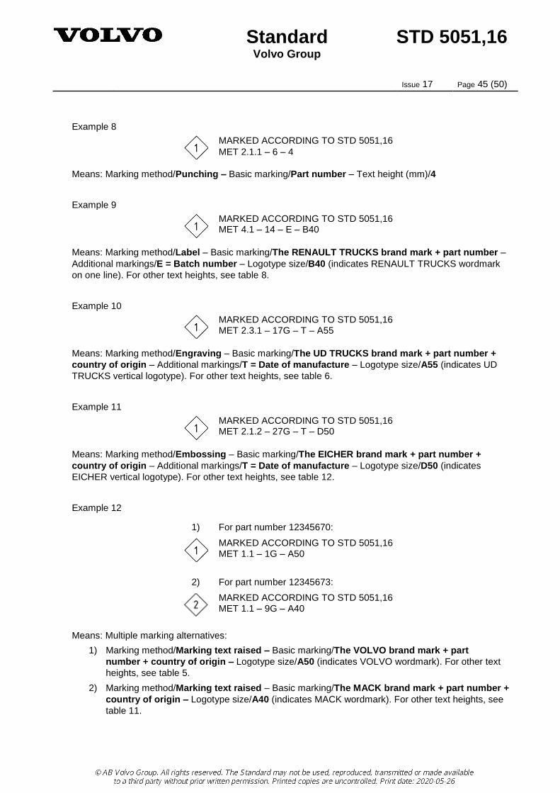
Example 8
MARKED ACCORDING TO STD 5051,16
MET 2.1.1 – 6 – 4
Means: Marking method/Punching – Basic marking/Part number – Text height (mm)/4
Example 9
MARKED ACCORDING TO STD 5051,16 MET 4.1 – 14 – E – B40
Means: Marking method/Label – Basic marking/The RENAULT TRUCKS brand mark + part number –
Additional markings/E = Batch number – Logotype size/B40 (indicates RENAULT TRUCKS wordmark
on one line). For other text heights, see table 8.
Example 10
MARKED ACCORDING TO STD 5051,16 MET 2.3.1 – 17G – T – A55
Means: Marking method/Engraving – Basic marking/The UD TRUCKS brand mark + part number +
country of origin – Additional markings/T = Date of manufacture – Logotype size/A55 (indicates UD
TRUCKS vertical logotype). For other text heights, see table 6.
Example 11
MARKED ACCORDING TO STD 5051,16 MET 2.1.2 – 27G – T – D50
Means: Marking method/Embossing – Basic marking/The EICHER brand mark + part number +
country of origin – Additional markings/T = Date of manufacture – Logotype size/D50 (indicates
EICHER vertical logotype). For other text heights, see table 12.
Example 12
1) For part number 12345670:
MARKED ACCORDING TO STD 5051,16 MET 1.1 – 1G – A50
2) For part number 12345673:
MARKED ACCORDING TO STD 5051,16 MET 1.1 – 9G – A40
Means: Multiple marking alternatives:
1) Marking method/Marking text raised – Basic marking/The VOLVO brand mark + part
number + country of origin – Logotype size/A50 (indicates VOLVO wordmark). For other text
heights, see table 5.
2) Marking method/Marking text raised – Basic marking/The MACK brand mark + part number +
country of origin – Logotype size/A40 (indicates MACK wordmark). For other text heights, see
table 11.

Standard STD 5051,16 Volvo Group
Issue 17 Page 46 (50)
Example 13
MARKED ACCORDING TO STD 5051,16 MET 2.1.3 – 27G – T – D65
Means: Marking method/Marking using a vibro pen – Basic marking/The EICHER brand mark + part
number + country of origin – Additional markings/T = Date of manufacture – Logotype size/D65
(indicates EICHER vertical logotype). For other text heights, see table 12.
Example 14
MARKED ACCORDING TO STD 5051,16 MET 4.1 – 14 – E – C20
Means: Marking method/Label – Basic marking/The RENAULT TRUCKS brand mark + part number –
Additional markings/E = Batch number – Logotype size/C20 (indicates RENAULT diamond). For other
text heights, see table 8.

Standard STD 5051,16 Volvo Group
Issue 17 Page 47 (50)
Appendix B Discontinued basic markings
The following designations shall no longer be used when the marking shall include country of origin, since
they do not require the inclusion of “MADE IN” prior to the country name.
Table B1
Designation Marking information Example
1 The VOLVO brand mark 1) + part number + country of origin
3 The VOLVO brand mark 1) + country of origin
4 Part number + country of origin
7 Country of origin only
9,10,11,12 Former MACK brand mark, not for new design.
13,14,15,16 Former Renault brand mark, not for new design.
17 The UD TRUCKS brand mark 1) + part number + country of origin
19 The UD TRUCKS brand mark + country of origin
23 The RENAULT TRUCKS brand mark 1) + part number + country of origin
25 The RENAULT TRUCKS brand mark + country of origin
27 The EICHER brand mark 1) + part number + country of origin
29 The EICHER brand mark + country of origin
31 The MACK brand mark 1) + part number + country of origin
33 The MACK brand mark + country of origin
35 The SDLG brand mark 1) + part number + country of origin
37 The SDLG brand mark 1) + country of origin

Standard STD 5051,16 Volvo Group
Issue 17 Page 48 (50)
Appendix C Discontinued supplementary markings
The following supplementary markings shall no longer be used for new design.
Table C1
Designation Marking information Example of marking text
Remarks
A The VOLVO logotype PENTA Applies only to Volvo Penta. Refers to the addition of "PENTA" to the VOLVO logotype to obtain the trademark "VOLVO PENTA".
C RENAULT TRUCKS logotype, on one line
RENAULT TRUCKS Applies only to Renault Trucks. See section 8.3 for details. (If the former RENAULT logotype is still to be used, the appendix applies.)
D RENAULT TRUCKS diamond
Applies only to Renault Trucks. See section 8.3 for details. (If the former RENAULT logotype is still to be used, the appendix applies.)
The following was previously accepted as an alternative for indicating part version in accordance with
supplementary marking H, as per table 3
Change field (alt. for supplementary marking H)
a)
• • • • • • • • •
a) = 1-line, 10 change conditions or part version suffixes
indicated
b)
• • • • • • •
b) = 2-lines, 10 change conditions or part version suffixes
indicated
• •
c)
• • • • •
c) = 3-lines, 09 change conditions or part version suffixes
indicated
• • • •
d)
• • • • • • •
d) = 20 change conditions or part version suffixes indicated
• • • • • • •
• • • • • •
Fig. C1
Standard STD 5051,16 Volvo Group
Issue 17 Page 49 (50)
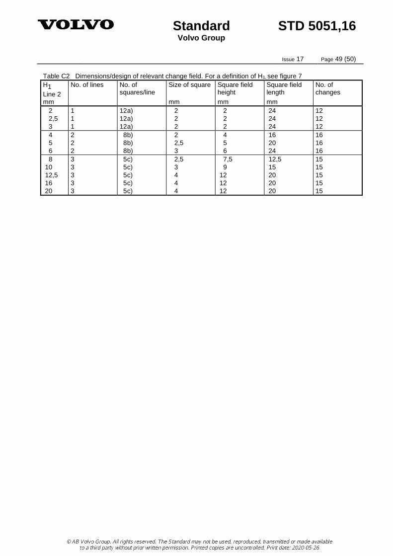
Table C2 Dimensions/design of relevant change field. For a definition of H1, see figure 7
H1 Line 2
No. of lines No. of squares/line
Size of square Square field height
Square field length
No. of changes
mm mm mm mm
2
2,5
3
1
1
1
12 a)
12 a)
12 a)
2
2
2
2
2
2
24
24
24
12
12
12
4
5
6
2
2
2
8 b)
8 b)
8 b)
2
2,5
3
4
5
6
16
20
24
16
16
16
8
10
12,5
16
20
3
3
3
3
3
5 c)
5 c)
5 c)
5 c)
5 c)
2,5
3
4
4
4
7,5
9
12
12
12
12,5
15
20
20
20
15
15
15
15
15
Standard STD 5051,16 Volvo Group
Issue 17 Page 50 (50)
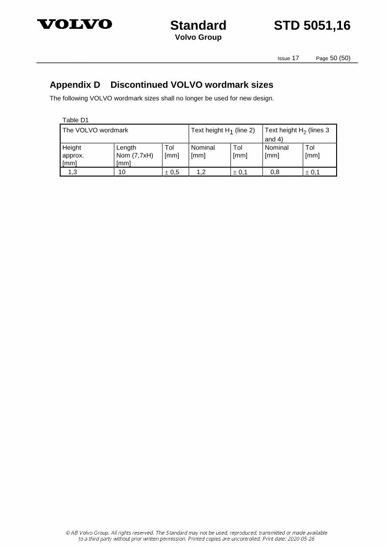
Appendix D Discontinued VOLVO wordmark sizes
The following VOLVO wordmark sizes shall no longer be used for new design.
Table D1
The VOLVO wordmark Text height H1 (line 2) Text height H2 (lines 3
and 4)
Height
approx.
[mm]
Length
Nom (7,7xH)
[mm]
Tol
[mm]
Nominal
[mm]
Tol
[mm]
Nominal
[mm]
Tol
[mm]
1,3 10 0,5 1,2 0,1 0,8 0,1