tfo cover06.cvr 12/1/06 9:43 am page 2 shaft seals · tfo_cover06.cvr 12/1/06 9:43 am page 2. 1...
TRANSCRIPT

Shaft SealsAA sseellff--ssttuuddyy gguuiiddee ffoorr iimmpprroovveedd tteecchhnniicciiaann
kknnoowwlleeddggee aanndd fflleeeett eeffffiicciieennccyy
TFO_Cover06.CVR 12/1/06 9:43 AM Page 2

11
TABLE OF CONTENTSIInnttrroodduuccttiioonn .. .. .. .. .. .. .. .. .. .. .. .. .. .. .. .. .. .. .. .. .. .. 22
CChhaapptteerr 11:: GGeenneerraall sseeaalliinngg .. .. .. .. .. .. .. .. .. .. .. 33
Brief history . . . . . . . . . . . . . . . . . . . . . . . . . 3
Sealing materials . . . . . . . . . . . . . . . . . . . . . 4
CChhaapptteerr 22:: SShhaafftt sseeaallss .. .. .. .. .. .. .. .. .. .. .. .. .. .. 66
Seal design/components . . . . . . . . . . . . . . . 6
How the seal works . . . . . . . . . . . . . . . . . . . 7
Retention/Exclusion . . . . . . . . . . . . . . . . . . . 8
Review . . . . . . . . . . . . . . . . . . . . . . . . . . . . . 9
CChhaapptteerr 33:: SSccoottsseeaallss .. .. .. .. .. .. .. .. .. .. .. .. .. .. 1111
The Scotseal system . . . . . . . . . . . . . . . . . 11
Scotseal construction . . . . . . . . . . . . . . . . 12
SKF TF Replacement Hubcaps . . . . . . . . . 15
SKF Lunar Hubs . . . . . . . . . . . . . . . . . . . . 16
Review . . . . . . . . . . . . . . . . . . . . . . . . . . . . 17
CChhaapptteerr 44:: SSccoottsseeaall rreeppllaacceemmeenntt .. .. .. .. .. 1199
Good practice tips . . . . . . . . . . . . . . . . . . . 19
Lubricants . . . . . . . . . . . . . . . . . . . . . . . . . 21
Seal replacement . . . . . . . . . . . . . . . . . . . . 22
Wheel end disassembly/assembly . . . . . . . 24
Bearing and seal installation . . . . . . . . . . . 27
Scotseal installation procedures. . . . . . . . . 28
Wheel bearing/end play adjustments . . . . 31
Wheel bearing/end play verification. . . . . . 32
Hubcap installation procedure . . . . . . . . . . 34
Review. . . . . . . . . . . . . . . . . . . . . . . . . . . . . 36
CChhaapptteerr 55:: WWhheeeell eenndd ggrreeaassee sseeaallss .. .. .. 3388
Seal installation . . . . . . . . . . . . . . . . . . . . . 38
Cleaning and inspection . . . . . . . . . . . . . . 39
Wheel re-assembly . . . . . . . . . . . . . . . . . . 41
Review . . . . . . . . . . . . . . . . . . . . . . . . . . . . 42
CChhaapptteerr 66:: NNoonn--wwhheeeell eenndd sseeaallss .. .. .. .. .. 4444
Synthetics . . . . . . . . . . . . . . . . . . . . . . . . . 44
Other synthetics . . . . . . . . . . . . . . . . . . . . 48
Wave seals . . . . . . . . . . . . . . . . . . . . . . . . . 50
Seal selection . . . . . . . . . . . . . . . . . . . . . . . 51
Oil seal installation . . . . . . . . . . . . . . . . . . 57
Review. . . . . . . . . . . . . . . . . . . . . . . . . . . . . 58
CChhaapptteerr 77:: WWeeaarr SSlleeeevveess .. .. .. .. .. .. .. .. .. .. .. 6622
SKF Speedi-Sleeves . . . . . . . . . . . . . . . . . 62
Speedi-Sleeve installation . . . . . . . . . . . . . 64
Review . . . . . . . . . . . . . . . . . . . . . . . . . . . . 66
CChhaapptteerr 88:: TTrroouubblleesshhoooottiinngg sshhaafftt sseeaallss aanndd
SSccoottsseeaallss .. .. .. .. .. .. .. .. .. .. .. .. .. .. .. .. .. .. .. .. .. .. .. 6688
Shaft seals . . . . . . . . . . . . . . . . . . . . . . . . . 68
Scotseal failure analysis . . . . . . . . . . . . . . 71
Review . . . . . . . . . . . . . . . . . . . . . . . . . . . . 80
2604293 TFO Self Study Guide_V3 12/1/06 9:50 AM Page 1

22
INTRODUCTIONThis book, produced for use by SKF distributors and
customers, should prove of practical value to engineers, fleet
mechanics, maintenance superintendents and anyone who can
benefit from a thorough understanding of seals. It will explain:
• How to select the best seal for any given application;
• How to improve performance with proper installation;
• How to spot – and correct – seal problems with
the least possible amount of time and money.
HHooww ttoo UUssee tthhiiss SSttuuddyy GGuuiiddeeThis self-study guide is programmed to increase performance
productivity. Each chapter consists of a logical organization of
material, technical diagrams and a short quiz to help you retain
what you study.
Start by carefully reading the text portion of each chapter.
Make notes or underline if you wish; this can help you
remember what you’ve read.
It does not matter whether you are a fast or slow learner.
At the end of the program, you will have learned the same
information – and should retain it – as well as any other
“student.”
The chapter quizzes are an important phase in self-study
learning since they are intended to reinforce the material
covered. The quiz questions are straightforward multiple choice
and true-false. There are no “trick questions.” Your answers can
easily be checked within the context of the chapter.
Complete each review in order before going on to the next
chapter. If you are not sure of an answer to a question, check
back in the chapter and review that portion again.
2604293 TFO Self Study Guide_V3 12/1/06 9:50 AM Page 2
33
CHAPTER 1 GENERAL SEALING
BBrriieeff HHiissttoorryy ooff tthhee SShhaafftt SSeeaall aanndd SSccoottsseeaallss
General Sealing TechnologyRadial shaft seals perform one and only one function – an
important one. They protect bearings serving as a barrier.
Bearings are necessary to reduce friction between an object
and the surface over which it is moved. Bearings need to be
continuously lubricated, and bearing life declines rapidly in the
absence of lubrication.
The seal plays a vital role in the bearing life as Henry Ford
discovered with the Model T. The greased wheels did not have
an adequate system to retain grease and it was flung out as
the wheels rotated creating a very dirty environment around
the wheel and deprived the bearing of lubrication. In 1926 SKF,
then Chicago Rawhide, provided an industry changing product,
the oil seal, coined “The Perfect Oil Seal”.
The radial shaft seals are designed to:
• Retain lubricants or fluids
• Exclude contamination
• Confine pressure
• Separate fluids
Seals are necessary for sealing in lubricants that are needed
to protect the bearings and to seal out dirt, water and other
contaminants.
Seal designs and materials are constantly being developed,
tested and improved. The testing is being done to conform with
today’s increased performance and durability requirements.
In the Heavy Truck and Bus market, seal design and material
will consider the application in which it is to be placed including
the lubrication media, seal location, external environment and
the operating condition. There are three categories of shaft
seals used in the truck and bus market.
11
2604293 TFO Self Study Guide_V3 12/1/06 9:50 AM Page 3

44
Grease SealsGreases have a relatively high viscosity and are thus relatively
easy to retain in the bearing arrangement. The grease seal
design usually includes a fairly lightly loaded spring. Grease
seals located on a truck or bus would also require the ability
to exclude contaminants, including dirt and water incorporating
radial and/or axial dirt lips.
Oil SealsLubricating oils, particularly relatively low-viscosity oils, are
much more difficult to retain in a bearing arrangement than
greases. The seal design and material will be critical to oil
retention. Therefore, spring loaded radial shaft seals are used
almost exclusively. For instance, the patented Waveseal® lip has
a sinusoidally formed lip edge which produces a pumping action
to the inside as well as outside irrespective of rotation direction.
Exclusion is often an important factor for oil seals, and radial
and axial dirt lips designed to exclude dirt and water are
incorporated as well.
ScotsealsSKF introduced Scotseals in the mid 1960’s as truck wheel
lubrication moved from grease to oil bath. The radial shaft seals
used at that time did not adequately retain the new oils used to
lubricate the bearings. Then SKF changed the industry again
with the Scotseal (Self Contained Oil Type), a unitized seal
design that retained the oil lubrication in the bearings and
excluded water and dirt road contaminants.
Sealing MaterialsSeal design is only part of the solution. Seals are manufac-
tured from a wide variety of elastomers determined by the
operating conditions. The elastomers used by SKF in heavy
truck include Nitriles, Hydrogenated Nitrile and Viton. The
temperature and wear capabilities for each are listed below.
2604293 TFO Self Study Guide_V3 12/1/06 9:50 AM Page 4

55
Operating Temperatures:The operating temperature capabilities for each of these
materials are listed to the right (fig. 1A & 1B).
Wear Resistance:The wear resistance capabilities for each of these are listed to
the right (fig. 2).
Chemical Resistance:The chemical resistance of the seal material is an important
factor to be considered when selecting a seal, particularly
with today’s harsh synthetic fluids used in heavy truck and bus
wheel ends. The chemical resistance of seals is also influenced
by temperature as well as pressure and the amount of media
present. Because of the complex relationships existing between
the individual factors, it is not possible to give universally valid
data regarding the chemical resistance of a particular material.
However, the Scotseal PlusXL and Scotseal Longlife are
designed with a specially formulated HNBR to be compatible
with today’s harsh wheel end synthetic fluids.
Heavy Truck SealsSeals are found in many locations on a truck or bus. (fig. 3)
The kind of seal depends on the location and function of the
seal. The diagram below lists the many places seals are located
on tractors, trucks, buses and trailers. Today, most wheel ends
are oil bath lubricated and use SKF’s Scotseal.
11Leather
Nitrile rubber
Duralip (X-NBR)
Duratemp (H-NBR)
Polyacrylate elastomer
Silicone rubber
Fluoro rubber
Polystrafluoroethylene
Temperature ˚Cffiigg.. 11AA
Leather
Nitrile rubber
Duralip (X-NBR)
Duratemp (H-NBR)
Polyacrylate elastomer
Silicone rubber
Fluoro rubber
Polystrafluoroethylene
Temperature ˚F
-40-76-112 -4 0 +122 +212 +302 +392 +482
Wear resistance
Silicone rubber
Polyacrytateelastomer
Nitrile rubber
Leather
Duralip (X-NBR)
Duratemp (H-NBR)
Fluoro rubber
Polytetrafluoroethylene
ffiigg.. 11BB
TThhiiss ddiiaaggrraamm sshhoowwss tthhee llooccaattiioonn ooff sseeaallss mmoosstt oofftteenn rreeppllaacceedd iinn ttrraaccttoorrss,, ttrruucckkss,, ttrraaiilleerrss
aanndd bbuusseess.. WWhheeeell oorr aaxxllee sseeaallss aarree mmoosstt oofftteenn bbaatthh lluubbrriiccaattiioonn ssyysstteemmss uussiinngg SSccoottsseeaallss ((ffiigg.. 33))..
ffiigg.. 22
2604293 TFO Self Study Guide_V3 12/1/06 9:50 AM Page 5

66
CHAPTER 2SHAFT SEALS
In this world of moving parts, whenever a shaft rotates,
it needs a bearing for smooth, effective operation.
In most cases, where there’s a bearing, you’ll find a seal
helping it to do its job better. In simple terms, a shaft seal is
a barrier.
Shaft seals are designed to:
• Retain lubricants or liquids
• Confine pressure
• Exclude dirt
• Separate fluids
Seals are necessary for sealing in lubricants that are
needed to protect the bearings and to seal out dirt, water
and contaminants. To do both jobs effectively, all seals demand
precise engineering and manufacturing.
Seal designs and materials are constantly being developed,
tested and improved. This testing is being done to conform with
today’s increased performance and durability requirements.
The media being sealed can be anything from light oil
to heavy grease, or even hot turbine gases. Wheel seals are
among the most common applications. However, in the case
of wheel seals, the shaft remains stationary and the wheel hub
rotates. The seal retains lube in the bearing, and at the same
time, protects the bearing from contaminants such as water,
dirt, dust and abrasives.
First, it must be decided which is more important: retention
of lubricant, exclusion of foreign matter or, in some cases, both.
SSeeaall DDeessiiggnnThe shaft seal is a small and simple looking product with
a big and important job. The following describes a typical seal
and the function of each of its components (fig. 1). Scotseals
will be covered in the next chapter. (Page 11)
SSeeaall CCoommppoonneennttss11.. OOuutteerr SShheellll ((CCaassee)).. The outer, cup-shaped, rigid structure
of the lip seal assembly acts as a protective cover for the
head of the sealing element and more importantly holds
the installed seal in place.
((ffiigg.. 11))..
2604293 TFO Self Study Guide_V3 12/1/06 9:50 AM Page 6

77
22
22.. IInnnneerr SShheellll ((CCaassee)).. A rigid cup-shaped component of a
seal assembly which is placed inside the outer seal case.
It can function as a reinforcing member, shield, spring
retainer or lip-clamping device.
33.. SSeeaalliinngg EElleemmeenntt.. The flexible elastomeric “working”
component of a lip seal assembly which rides against
the shaft.
44.. PPrriimmaarryy LLiipp.. The flexible, spring-loaded elastomeric lip
component of the sealing element which contacts the
rotating surface.
55.. SSeeccoonnddaarryy LLiipp ((AAuuxxiilliiaarryy LLiipp)).. A short, non-spring-
loaded lip of the sealing element which is located at the
outside seal face of a radial lip seal. It is used to exclude
contaminants.
66.. GGaarrtteerr SSpprriinngg.. A coiled wire spring with its ends
connected. It is used for maintaining a sealing force
between the sealing element and sealing surface.
HHooww TThhee SSeeaall WWoorrkkssThe following is a review of how the seal components
work together to retain lubricants, confine pressure, exclude
contaminants and separate liquids.
Retention SealsSeals designed to retain lubricants or keep normal
operating pressure in the bearing cavity are known as retention
seals.
Retention seals (normally spring-loaded) are not
recommended for more than light dirt exclusion. Because
of their specific function, they rarely face toward dirt or
heavy contaminants.
Exclusion SealsThese seals prevent dirt, water and contaminants from
entering the bearing assembly. There is a wide variety
of exclusion seals. Some have a single lip and no spring
reinforcement. With others, the lip action is at the outside
diameter of the seal. Still others were created especially
for mud applications.
Exclusion seals, with lips pointing outward, can be
kept lubricated and clear of dirt by purging (forcing grease
through them).
2604293 TFO Self Study Guide_V3 12/1/06 9:50 AM Page 7

88
RReetteennttiioonn//EExxcclluussiioonnMany applications require the seal to perform both the
retention and exclusion functions at the same time. For
example, the seal may need to confine a lubricant, as well as
exclude road dust, mud, water, or other highway contaminants.
For applications that require both lube retention and
dirt exclusion, a special type of protection is needed, either
a combination of two seals, or dual sealing elements within
one assembly.
The kind of seal (grease vs. oil bath, for example) depends on
the location and function of the seal.
Wheel or axle seals are either grease seals or oil bath seals
(Scotseal-Self Contained Oil Type Seals).
2604293 TFO Self Study Guide_V3 12/1/06 9:50 AM Page 8

99
22
To take this test, simply place a card or sheet of paper under the first question.
After you’ve read it (and answered it to yourself), slide the paper down below
the next question. The correct answer to the first problem will appear directly to
the right of the new question. Be sure not to skip any of the questions. This
learning technique assures more than four times the normal retention rate for
even this technical subject.
01. A shaft seal is a barrier designed to .❏ a. retain lubricants or liquids and exclude dirt❏ b. confine pressure ❏ c. separate fluids ❏ d. all of the above
1. D
02. A typical vehicle may require .❏ a. steering seals❏ b. transmission rear seals❏ c. front crank seals❏ d. all of the above
2. D
03. Another name for the outer shell of the seal is the outer .❏ a. lip❏ b. case❏ c. cone❏ d. spring
3. B
04. Every rotating shaft requires a bearing and a seal for smooth, effective operation.
❏ True ❏ False4. T
05 A shaft seal is a barrier designed only to confine pressure.❏ True ❏ False
5. F
CHAPTER 2 REVIEW
2604293 TFO Self Study Guide_V3 12/1/06 9:50 AM Page 9
1100
6. Seals are needed to seal in lubricants necessary for the bearings, and to seal out dirt, water, and contaminants.
❏ True ❏ False6. T
7. If the seal’s basic job is to retain lubricants or liquid, the seal lip must face toward the lubricant or pressure being retained.
❏ True ❏ False7. T
8. If the seal’s basic job is to exclude contaminants, the lip of the seal should face toward the bearing, instead of toward the contaminants.
❏ True ❏ False8. F
9. Spring-loaded seals designed to retain lubricants or keep pressure in the bearing cavity are known as exclusion seals.
❏ True ❏ False9. F
10. Retention seals stop dirt, water, and contaminants from entering the bearing cavity.
❏ True ❏ False10. F
11. Seal components include an outer shell, inner shell, sealing element, primary lip and garter spring.
❏ True ❏ False11. T
2604293 TFO Self Study Guide_V3 12/1/06 9:50 AM Page 10
1111
33
CHAPTER 3SCOTSEALS
TThhee SSccoottsseeaall ssyysstteemmIn addition to the standard line of grease seals, SKF has
designed a complete oil bath sealing system, Scotseal, for trailer
wheels, tractor front and drive wheels, and bus wheels.
Wheel ends go from grease to oilIn the late 1950’s, the trucking industry began to bathe
wheel bearings in oil instead of packing them in grease. But
those early designs had a problem: the sealing element was
pressed into the wheel. It turned with the wheel. At high
speeds, centrifugal force would lift the sealing lip off the
axle – allowing oil to leak.
The solution was to use extra stiff leather with a heavy
tension spring to combat centrifugal force. But this added
pressure wore grooves in the axle.
So, a special ring was pressed over the axle. For years, this
early design was the only one available. Then, SKF introduced
the Self Contained Oil Type Seal – Scotseal, now known as
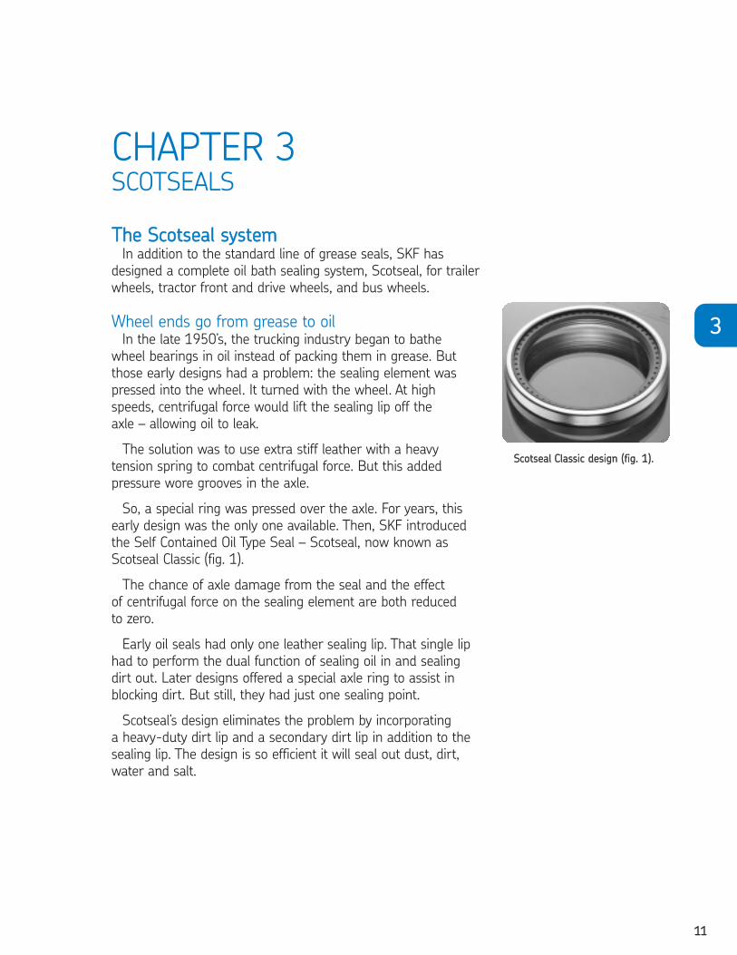
Scotseal Classic (fig. 1).
The chance of axle damage from the seal and the effect
of centrifugal force on the sealing element are both reduced
to zero.
Early oil seals had only one leather sealing lip. That single lip
had to perform the dual function of sealing oil in and sealing
dirt out. Later designs offered a special axle ring to assist in
blocking dirt. But still, they had just one sealing point.
Scotseal’s design eliminates the problem by incorporating
a heavy-duty dirt lip and a secondary dirt lip in addition to the
sealing lip. The design is so efficient it will seal out dust, dirt,
water and salt.
SSccoottsseeaall CCllaassssiicc ddeessiiggnn ((ffiigg.. 11))..
2604293 TFO Self Study Guide_V3 12/1/06 9:50 AM Page 11
1122
SSccoottsseeaall®® FFaammiillyy ooff WWhheeeell SSeeaallssThe Scotseal family of seals features three product variations
that are suited to your particular preference, application and
environment. The entire Scotseal family offers you the right seal-
ing solution for every kind of wheel end maintenance. The brand
recognition, along with the outstanding quality and value, insures
that you are installing the optimum seal for your operation.
The Scotseal Classic has become the trucking industry standard
and best value for more than 30 years. The Scotseal Longlife
provides you with an extended life seal with superior tolerance to
higher wheel end temperatures, and is compatible with synthetic
lubricants. The Scotseal PlusXL provides you with an extended life
seal with superior tolerance to higher wheel end temperatures,
and is compatible with synthetic lubricants.
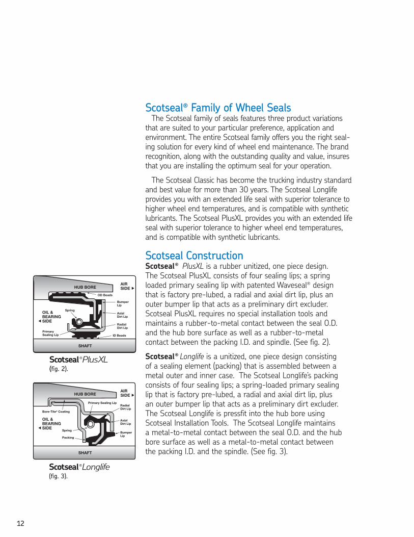
SSccoottsseeaall CCoonnssttrruuccttiioonn Scotseal® PlusXL is a rubber unitized, one piece design.
The Scotseal PlusXL consists of four sealing lips; a spring
loaded primary sealing lip with patented Waveseal® design
that is factory pre-lubed, a radial and axial dirt lip, plus an
outer bumper lip that acts as a preliminary dirt excluder.
Scotseal PlusXL requires no special installation tools and
maintains a rubber-to-metal contact between the seal O.D.
and the hub bore surface as well as a rubber-to-metal
contact between the packing I.D. and spindle. (See fig. 2).
Scotseal® Longlife is a unitized, one piece design consisting
of a sealing element (packing) that is assembled between a
metal outer and inner case. The Scotseal Longlife’s packing
consists of four sealing lips; a spring-loaded primary sealing
lip that is factory pre-lubed, a radial and axial dirt lip, plus
an outer bumper lip that acts as a preliminary dirt excluder.
The Scotseal Longlife is pressfit into the hub bore using
Scotseal Installation Tools. The Scotseal Longlife maintains
a metal-to-metal contact between the seal O.D. and the hub
bore surface as well as a metal-to-metal contact between
the packing I.D. and the spindle. (See fig. 3).
Scotseal®PlusXL((ffiigg.. 22))..
Scotseal®Longlife((ffiigg.. 33))..
2604293 TFO Self Study Guide_V3 12/1/06 9:50 AM Page 12
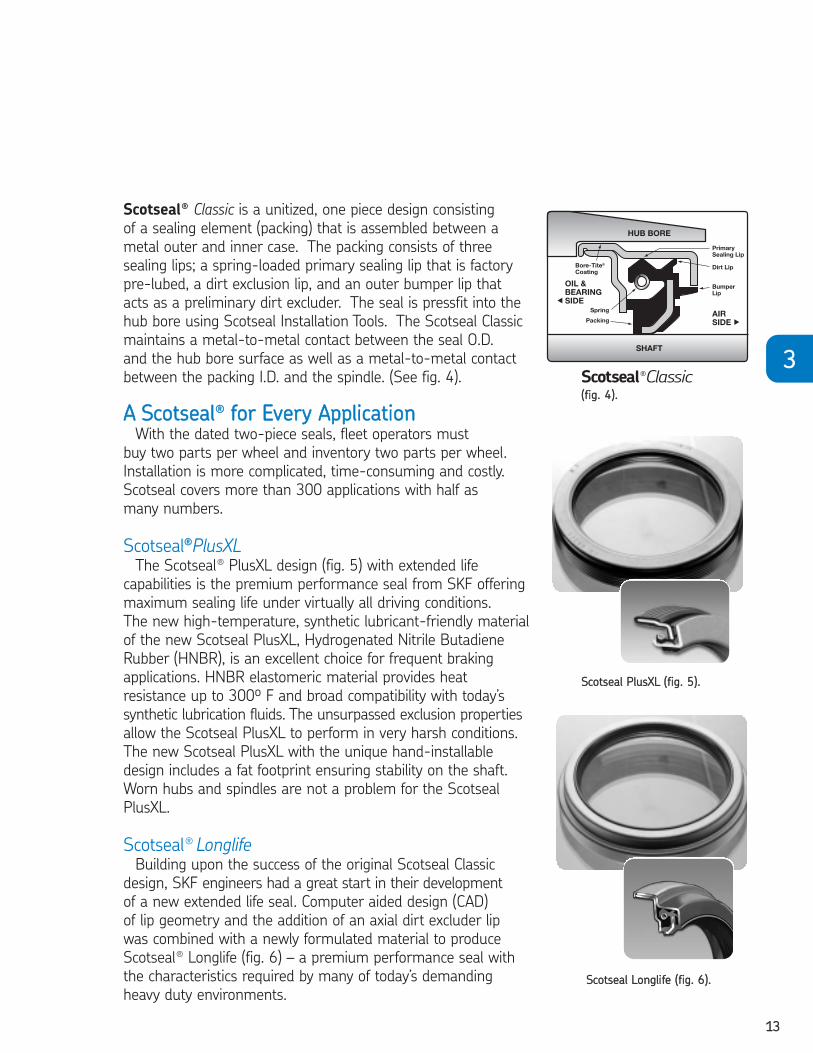
Scotseal® Classic is a unitized, one piece design consisting
of a sealing element (packing) that is assembled between a
metal outer and inner case. The packing consists of three
sealing lips; a spring-loaded primary sealing lip that is factory
pre-lubed, a dirt exclusion lip, and an outer bumper lip that
acts as a preliminary dirt excluder. The seal is pressfit into the
hub bore using Scotseal Installation Tools. The Scotseal Classic
maintains a metal-to-metal contact between the seal O.D.
and the hub bore surface as well as a metal-to-metal contact
between the packing I.D. and the spindle. (See fig. 4).
AA SSccoottsseeaall®® ffoorr EEvveerryy AApppplliiccaattiioonnWith the dated two-piece seals, fleet operators must
buy two parts per wheel and inventory two parts per wheel.
Installation is more complicated, time-consuming and costly.
Scotseal covers more than 300 applications with half as
many numbers.
Scotseal®®PlusXLThe Scotseal® PlusXL design (fig. 5) with extended life
capabilities is the premium performance seal from SKF offering
maximum sealing life under virtually all driving conditions.
The new high-temperature, synthetic lubricant-friendly material
of the new Scotseal PlusXL, Hydrogenated Nitrile Butadiene
Rubber (HNBR), is an excellent choice for frequent braking
applications. HNBR elastomeric material provides heat
resistance up to 300º F and broad compatibility with today’s
synthetic lubrication fluids. The unsurpassed exclusion properties
allow the Scotseal PlusXL to perform in very harsh conditions.
The new Scotseal PlusXL with the unique hand-installable
design includes a fat footprint ensuring stability on the shaft.
Worn hubs and spindles are not a problem for the Scotseal
PlusXL.
Scotseal® LonglifeBuilding upon the success of the original Scotseal Classic
design, SKF engineers had a great start in their development
of a new extended life seal. Computer aided design (CAD)
of lip geometry and the addition of an axial dirt excluder lip
was combined with a newly formulated material to produce
Scotseal® Longlife (fig. 6) – a premium performance seal with
the characteristics required by many of today’s demanding
heavy duty environments.
1133
33
SSccoottsseeaall PPlluussXXLL ((ffiigg.. 55))..
SSccoottsseeaall LLoonngglliiffee ((ffiigg.. 66))..
Scotseal®Classic((ffiigg.. 44))..
2604293 TFO Self Study Guide_V3 12/1/06 9:50 AM Page 13
1144
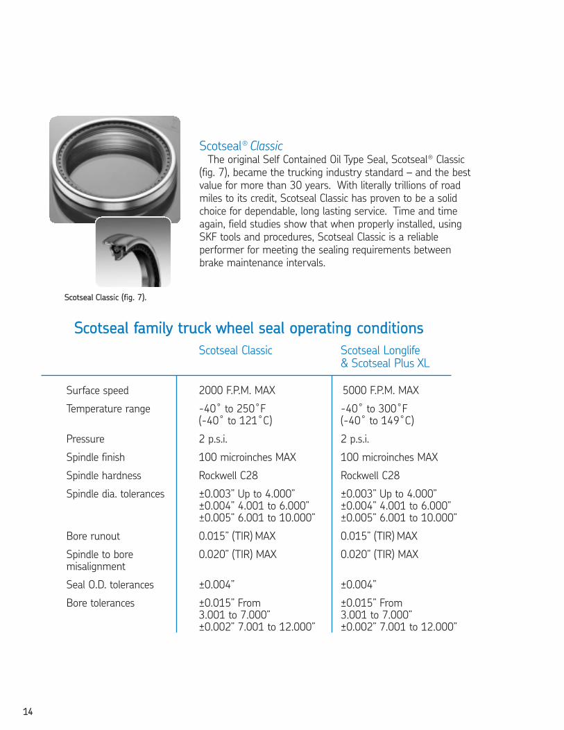
Scotseal® ClassicThe original Self Contained Oil Type Seal, Scotseal® Classic
(fig. 7), became the trucking industry standard – and the best
value for more than 30 years. With literally trillions of road
miles to its credit, Scotseal Classic has proven to be a solid
choice for dependable, long lasting service. Time and time
again, field studies show that when properly installed, using
SKF tools and procedures, Scotseal Classic is a reliable
performer for meeting the sealing requirements between
brake maintenance intervals.
SSccoottsseeaall ffaammiillyy ttrruucckk wwhheeeell sseeaall ooppeerraattiinngg ccoonnddiittiioonnss
Scotseal Classic Scotseal Longlife & Scotseal Plus XL
Surface speed 2000 F.P.M. MAX 5000 F.P.M. MAX
Temperature range -40˚ to 250˚F -40˚ to 300˚F(-40˚ to 121˚C) (-40˚ to 149˚C)
Pressure 2 p.s.i. 2 p.s.i.
Spindle finish 100 microinches MAX 100 microinches MAX
Spindle hardness Rockwell C28 Rockwell C28
Spindle dia. tolerances ±0.003” Up to 4.000” ±0.003” Up to 4.000”±0.004” 4.001 to 6.000” ±0.004” 4.001 to 6.000”±0.005” 6.001 to 10.000” ±0.005” 6.001 to 10.000”
Bore runout 0.015” (TIR) MAX 0.015” (TIR) MAX
Spindle to bore 0.020” (TIR) MAX 0.020” (TIR) MAXmisalignment
Seal O.D. tolerances ±0.004” ±0.004”
Bore tolerances ±0.015” From ±0.015” From3.001 to 7.000” 3.001 to 7.000”±0.002” 7.001 to 12.000” ±0.002” 7.001 to 12.000”
SSccoottsseeaall CCllaassssiicc ((ffiigg.. 77))..
2604293 TFO Self Study Guide_V3 12/1/06 9:50 AM Page 14
1155
33
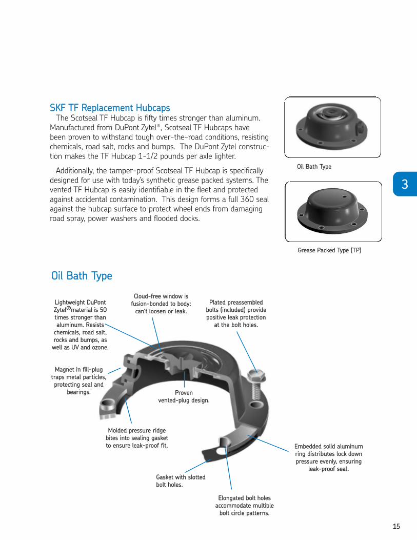
SSKKFF TTFF RReeppllaacceemmeenntt HHuubbccaappssThe Scotseal TF Hubcap is fifty times stronger than aluminum.
Manufactured from DuPont Zytel®, Scotseal TF Hubcaps have
been proven to withstand tough over-the-road conditions, resisting
chemicals, road salt, rocks and bumps. The DuPont Zytel construc-
tion makes the TF Hubcap 1-1/2 pounds per axle lighter.
Additionally, the tamper-proof Scotseal TF Hubcap is specifically
designed for use with today's synthetic grease packed systems. The
vented TF Hubcap is easily identifiable in the fleet and protected
against accidental contamination. This design forms a full 360 seal
against the hubcap surface to protect wheel ends from damaging
road spray, power washers and flooded docks.
CClloouudd--ffrreeee wwiinnddooww iiss
ffuussiioonn--bboonnddeedd ttoo bbooddyy::
ccaann’’tt lloooosseenn oorr lleeaakk..
LLiigghhttwweeiigghhtt DDuuPPoonntt
ZZyytteell®®mmaatteerriiaall iiss 5500
ttiimmeess ssttrroonnggeerr tthhaann
aalluummiinnuumm.. RReessiissttss
cchheemmiiccaallss,, rrooaadd ssaalltt,,
rroocckkss aanndd bbuummppss,, aass
wweellll aass UUVV aanndd oozzoonnee..
PPrroovveenn
vveenntteedd--pplluugg ddeessiiggnn..
EElloonnggaatteedd bboolltt hhoolleess
aaccccoommmmooddaattee mmuullttiippllee
bboolltt cciirrccllee ppaatttteerrnnss..
MMoollddeedd pprreessssuurree rriiddggee
bbiitteess iinnttoo sseeaalliinngg ggaasskkeett
ttoo eennssuurree lleeaakk--pprrooooff ffiitt..
PPllaatteedd pprreeaasssseemmbblleedd
bboollttss ((iinncclluuddeedd)) pprroovviiddee
ppoossiittiivvee lleeaakk pprrootteeccttiioonn
aatt tthhee bboolltt hhoolleess..
GGaasskkeett wwiitthh ssllootttteedd
bboolltt hhoolleess..
EEmmbbeeddddeedd ssoolliidd aalluummiinnuumm
rriinngg ddiissttrriibbuutteess lloocckk ddoowwnn
pprreessssuurree eevveennllyy,, eennssuurriinngg
lleeaakk--pprrooooff sseeaall..
MMaaggnneett iinn ffiillll--pplluugg
ttrraappss mmeettaall ppaarrttiicclleess,,
pprrootteeccttiinngg sseeaall aanndd
bbeeaarriinnggss..
OOiill BBaatthh TTyyppee
OOiill BBaatthh TTyyppee
GGrreeaassee PPaacckkeedd TTyyppee ((TTPP))
2604293 TFO Self Study Guide_V3 12/1/06 9:50 AM Page 15

1166
SSKKFF LLUUNNAARR ttrruucckk hhuubbss
Unlike conventional wheel ends, with separately installed,
replaced and adjusted components, SKF LUNAR hubs, (for
Longlife Unitized No Assembly Required), are fully integrated,
factory-assembled units that are designed for extended
trouble-free operation. Because they require virtually no
maintenance for the life of the hub, these units have become
a popular original equipment choice on new steer, drive and
trailer axles.
As with all long life safety critical components, these units
still require regular inspection. Refer to the truck or trailer
manufacturer for specific inspection intervals and procedures.
Greater wheel-end stabilityUnder aggressive cornering, today’s vehicles exert lateral
separation forces on the bearings in excess of 6 tons. In a
conventional hub, with its typical bearing clearance, these
turning forces cause movement in the bearing arrangement.
In an SKF LUNAR hub, designed for a spindle that is straight,
rather than tapered, an 8 ton clamping load is placed across
the inner rings. This creates a rigid system that keeps the
bearings and seal stable during excessive load conditions.
The result? Higher safety, reduced maintenance.
LLUUNNAARR sstteeeerr aaxxllee hhuubb
LLUUNNAARR ttrraaiilleerr aaxxllee hhuubb
2604293 TFO Self Study Guide_V3 12/1/06 9:50 AM Page 16
1177
33
CHAPTER 3 REVIEWTo take this test, simply place a card or sheet of paper under the first question.
After you’ve read it (and answered it to yourself), slide the paper down below the
next question. The correct answer to the first problem will appear directly to the
right of the new question. Be sure not to skip any of the questions. This learning
technique assures more than four times the normal retention rate for even this
technical subject.
1. SKF designed the Scotseal specifically for wheels.❏ a. trailer❏ b. bus❏ c. tractor front❏ d. all of the above
1. D2. Scotseal’s design is so efficient that it seals out .
❏ a. water❏ b. salt❏ c. dust❏ d. all of the above
2. D3. The Scotseal design utilizes a .
❏ a. heavy-duty dirt lip❏ b. secondary dirt lip❏ c. sealing lip❏ d. all of the above
3. D4. With Scotseal Classic, is reduced to zero.
❏ a. the chance of axle damage from the seal❏ b. the effect of centrifugal force on the sealing element❏ c. both of the above❏ d. neither of the above
4. C5. The Scotseal Classic’s O.D. is coated with which contains no
abrasives or thinners.❏ a. Viton❏ b. Bore-Tite❏ c. engine oil❏ d. Lexan
5. B
2604293 TFO Self Study Guide_V3 12/1/06 9:50 AM Page 17
1188
6. With a Scotseal, everything including the sealing element turns.❏ True ❏ False
6. F7. The oil leaks suffered by the trucking industry of the late 1950’s
occurred because centrifugal force lifted the sealing lip from the axle.❏ True ❏ False
7. T8. Scotseal’s sealing lip is both elastomeric and spring-loaded.
❏ True ❏ False8. T
2604293 TFO Self Study Guide_V3 12/1/06 9:50 AM Page 18
1199
CHAPTER 4 SCOTSEAL REPLACEMENT
44
Faulty installation is one of the most common reasons a seal fails. No matter how
well made a seal is, incorrect installation can make even a new seal worthless.
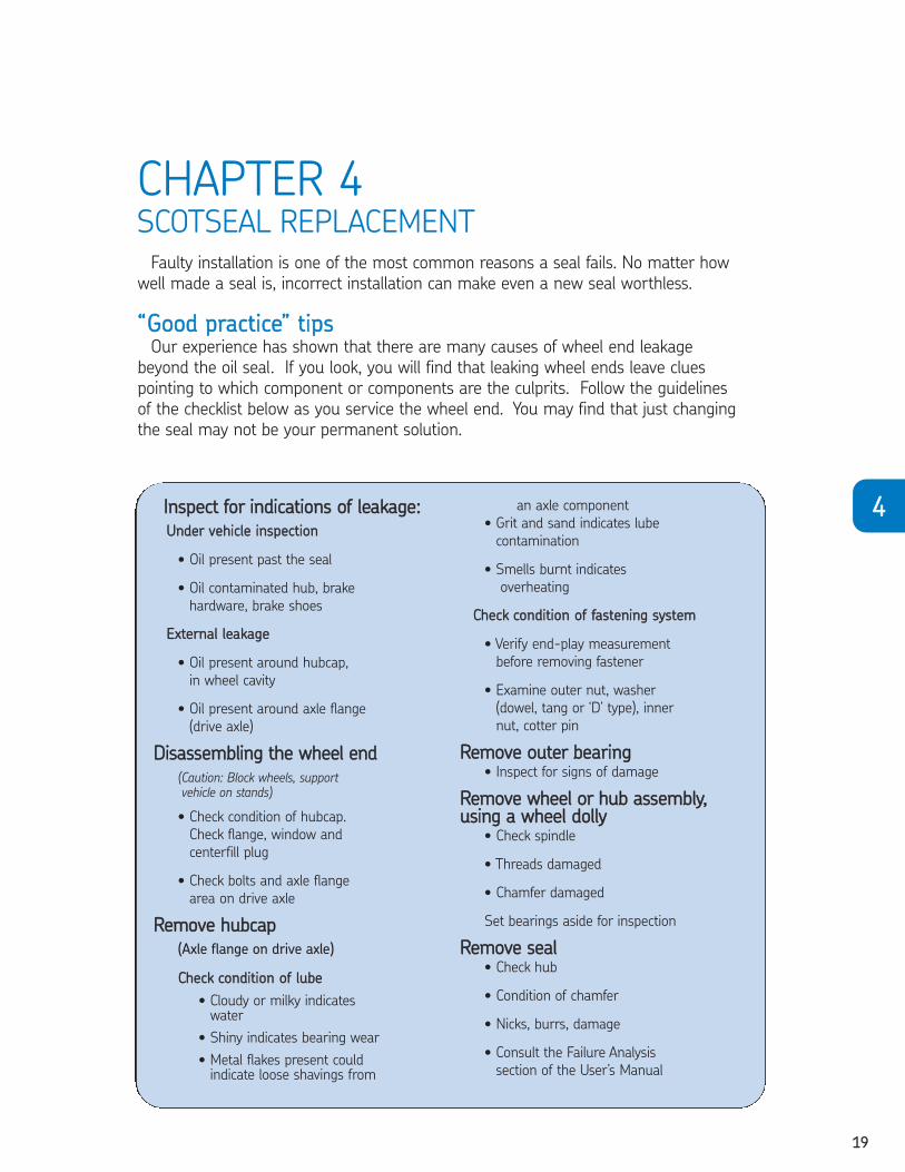
““GGoooodd pprraaccttiiccee”” ttiippss Our experience has shown that there are many causes of wheel end leakage
beyond the oil seal. If you look, you will find that leaking wheel ends leave clues
pointing to which component or components are the culprits. Follow the guidelines
of the checklist below as you service the wheel end. You may find that just changing
the seal may not be your permanent solution.
IInnssppeecctt ffoorr iinnddiiccaattiioonnss ooff lleeaakkaaggee::
UUnnddeerr vveehhiiccllee iinnssppeeccttiioonn
• Oil present past the seal
• Oil contaminated hub, brake
hardware, brake shoes
EExxtteerrnnaall lleeaakkaaggee
• Oil present around hubcap,
in wheel cavity
• Oil present around axle flange
(drive axle)
DDiissaasssseemmbblliinngg tthhee wwhheeeell eenndd
(Caution: Block wheels, supportvehicle on stands)
• Check condition of hubcap.
Check flange, window and
centerfill plug
• Check bolts and axle flange
area on drive axle
RReemmoovvee hhuubbccaapp
(Axle flange on drive axle)
CChheecckk ccoonnddiittiioonn ooff lluubbee
• Cloudy or milky indicates water
• Shiny indicates bearing wear
• Metal flakes present couldindicate loose shavings from
an axle component
• Grit and sand indicates lube
contamination
• Smells burnt indicates
overheating
CChheecckk ccoonnddiittiioonn ooff ffaasstteenniinngg ssyysstteemm
• Verify end-play measurement
before removing fastener
• Examine outer nut, washer
(dowel, tang or ‘D’ type), inner
nut, cotter pin
RReemmoovvee oouutteerr bbeeaarriinngg• Inspect for signs of damage
RReemmoovvee wwhheeeell oorr hhuubb aasssseemmbbllyy,,uussiinngg aa wwhheeeell ddoollllyy
• Check spindle
• Threads damaged
• Chamfer damaged
Set bearings aside for inspection
RReemmoovvee sseeaall• Check hub
• Condition of chamfer
• Nicks, burrs, damage
• Consult the Failure Analysis
section of the User’s Manual
2604293 TFO Self Study Guide_V3 12/1/06 9:50 AM Page 19

2200
HHeellppffuull hhiinnttss
• Do not use chisels, impact wrenches and torches
• Do not use hammers directly on seals or bearings
Bearings must be cleaned for inspection and re-use.
Use only clean solvents – effectiveness of solvent in
removing old lubricant depends on how clean the solvent is.
Good cleaning requires proper equipment such as:
• Solvent bath
• A filter system and regular
changes of the solvent and the filters
TThhee iimmppoorrttaannccee ooff pprrooppeerr lluubbrriiccaannttssIt is important to use the proper amount of lubricant
when installing wheel end components. If the proper
amount of lubricant is not used, the working combination
of the bearings, seals and brakes can create a “heat sink,”
ultimately damaging the working condition of the entire
wheel end.
Do not use compressed air. After cleaning, dry with
a clean paper towel or a clean rag. Air jets cause
small abrasive particles to become jammed in
between the bearing surfaces.
• Stay organized – a messy
shop is dangerous and
inefficient.
• Keep loose components
together
• It is important to not mix
wheel-end components
– bearings are “mates”
that wear together. This
includes new bearings.
2604293 TFO Self Study Guide_V3 12/1/06 9:50 AM Page 20

2211
44
Running conditions
(Road surface, weather, terrain, speed and load)
Hardening
or destruction
of seal lip
Lube on thebrakes
Highertemperatures
Lubedeterioration
Hot running causesphysical damage
Lube leakage
IInnssppeeccttiioonn ooff lluubbrriiccaannttInspection of grease or oil can provide a clue to other
problems. Remove a sample from the wheel end and check
for the following:
• Presence of
contaminants
• Burnt aroma
• Presence of water
Prior to re-installing bearings, always check for the proper lubricant.
Wheel end lubricants are formulated to match the requirements of the
truck and bearing manufacturer.
• Always use
specified lubricant
• Do not mix lubricants
• Chemical interaction
between lubricants
and seal materials can
damage the seal
• Whenever possible, use
a grease packer
GGrreeaassee aanndd ooiill lluubbrriiccaannttssThe truck or trailer manufacturer has pre-determined that
the wheel-end assembly is to be lubricated by grease or oil. The
importance of following the manufacturer’s specifications cannot
be over emphasized – never change or mix grease and oil in the
same assembly! AAllwwaayyss uussee lluubbrriiccaannttss aass rreeccoommmmeennddeedd
bbyy tthhee mmaannuuffaaccttuurreerr..
GGrreeaassee lluubbrriiccaatteedd wwhheeeell--eennddssFor proper lubrication, the grease must be packed into the
cavities between the rollers and cage of the bearing cone. A
mechanical grease packer is recommended in order to improve
on the common procedure of filling the grease by hand. Also
apply a light film of grease to the axle spindle for corrosion
protection.TTyyppiiccaall mmeecchhaanniiccaall ggrreeaassee ppaacckkeerr
2604293 TFO Self Study Guide_V3 12/1/06 9:50 AM Page 21

2222
TTwwoo ppiieeccee sseeaall rreeppllaacceemmeenntt vvss.. SSccoottsseeaall rreeppllaacceemmeenntt
Some seal manufacturers utilize a
two-piece design that includes a wear
sleeve and an oil seal (fig. 1). Be aware
that the original seal with the sleeve will
have a larger ID dimension compared to
the Scotseal® unitized design. Shown in
fig. 2 is the two components assembled
on the spindle. Assuring the correct seal
requires specifications that match the
spindle sealing surface diameter and the hub seal bore.
For example (fig. 3 and 3a),
the seal component has an ID of
4.733” compared to the spindle
diameter of 4.625”. The sleeve
component has an ID of 4.625”
matching the spindle diameter.
At times, in error, a comparison
is made between the two-piece
style seal component and a
unitized Scotseal replacement.
The ID dimensions will differ.
Always check the spindle for
any sleeve or axle ring and
remove. Seals of this nature
and Scotseals press into the
hub bore, therefore outside
diameters will match.
HHuubb bboorree vvss.. sseeaall bboorreeIn some applications an oil seal will press fit into the bearing
bore (fig. 4) instead of the seal or hub bore. Confusion arises when
a replacement seal appears too large in the OD dimension when
interpretation indicates that the replacement seal is a hub bore
installation, but in fact it is a bearing bore installation. (fig. 5).
Figure 1 Figure 2
Figure 3
Figure 3a
Figure 4 Figure 5
Seal
4.733” ID
6.006 OD
4.625” ID 4.625” ID
6.006 OD
Sleeve Scotseals
Spindle diameter 4.625”
Assembled seal and sleeve
Seal
Sleeve
Hub Bore
BearingBore
Hub Bore
BearingBore
2604293 TFO Self Study Guide_V3 12/1/06 9:50 AM Page 22
2233
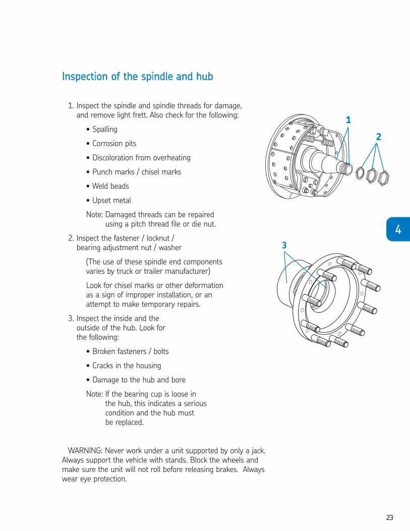
IInnssppeeccttiioonn ooff tthhee ssppiinnddllee aanndd hhuubb
1. Inspect the spindle and spindle threads for damage,
and remove light frett. Also check for the following:
• Spalling
• Corrosion pits
• Discoloration from overheating
• Punch marks / chisel marks
• Weld beads
• Upset metal
Note: Damaged threads can be repaired
using a pitch thread file or die nut.
2. Inspect the fastener / locknut /
bearing adjustment nut / washer
(The use of these spindle end components
varies by truck or trailer manufacturer)
Look for chisel marks or other deformation
as a sign of improper installation, or an
attempt to make temporary repairs.
3. Inspect the inside and the
outside of the hub. Look for
the following:
• Broken fasteners / bolts
• Cracks in the housing
• Damage to the hub and bore
Note: If the bearing cup is loose in
the hub, this indicates a serious
condition and the hub must
be replaced.
WARNING: Never work under a unit supported by only a jack.
Always support the vehicle with stands. Block the wheels and
make sure the unit will not roll before releasing brakes. Always
wear eye protection.
3
1
2
44
2604293 TFO Self Study Guide_V3 12/1/06 9:50 AM Page 23
2244
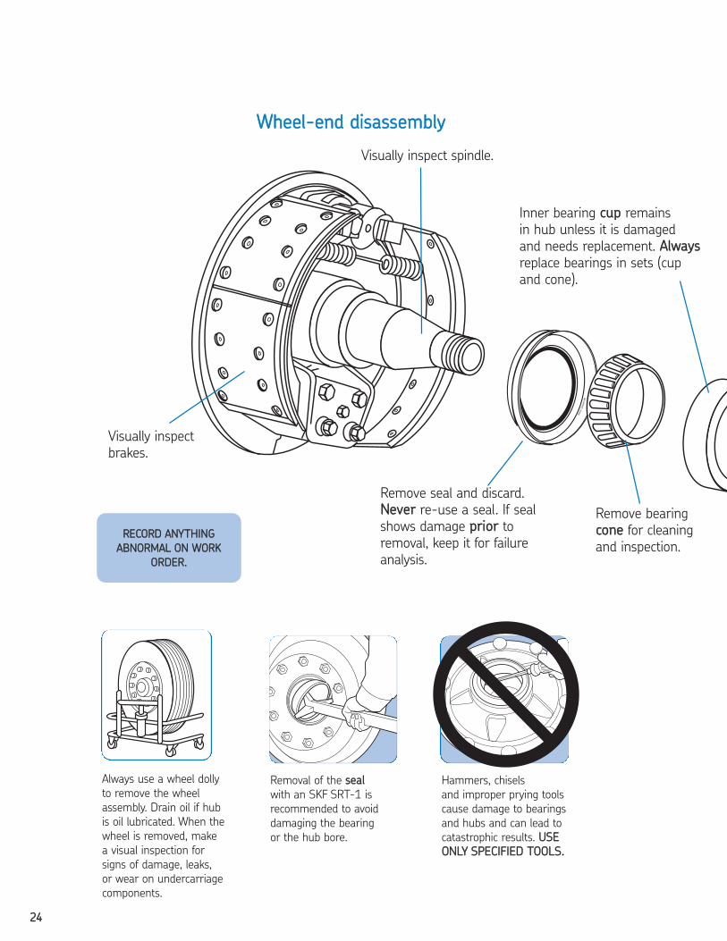
WWhheeeell--eenndd ddiissaasssseemmbbllyy
Inner bearing ccuupp remains
in hub unless it is damaged
and needs replacement. AAllwwaayyss
replace bearings in sets (cup
and cone).
Removal of the sseeaall
with an SKF SRT-1 is
recommended to avoid
damaging the bearing
or the hub bore.
Always use a wheel dolly
to remove the wheel
assembly. Drain oil if hub
is oil lubricated. When the
wheel is removed, make
a visual inspection for
signs of damage, leaks,
or wear on undercarriage
components.
Hammers, chisels
and improper prying tools
cause damage to bearings
and hubs and can lead to
catastrophic results. UUSSEE
OONNLLYY SSPPEECCIIFFIIEEDD TTOOOOLLSS..
Remove seal and discard.
NNeevveerr re-use a seal. If seal
shows damage pprriioorr to
removal, keep it for failure
analysis.
Visually inspect
brakes.
Visually inspect spindle.
Remove bearing
ccoonnee for cleaning
and inspection.RREECCOORRDD AANNYYTTHHIINNGG
AABBNNOORRMMAALL OONN WWOORRKK
OORRDDEERR..
2604293 TFO Self Study Guide_V3 12/1/06 9:50 AM Page 24
2255
44
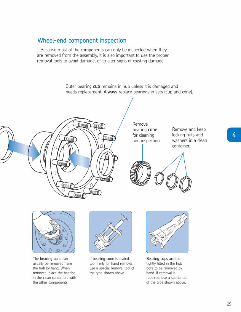
WWhheeeell--eenndd ccoommppoonneenntt iinnssppeeccttiioonn
The bbeeaarriinngg ccoonnee can
usually be removed from
the hub by hand. When
removed, place the bearing
in the clean containers with
the other components.
If bbeeaarriinngg ccoonnee is seated
too firmly for hand removal,
use a special removal tool of
the type shown above.
BBeeaarriinngg ccuuppss are too
tightly fitted in the hub
bore to be removed by
hand. If removal is
required, use a special tool
of the type shown above.
Remove
bearing ccoonnee
for cleaning
and inspection.
Outer bearing ccuupp remains in hub unless it is damaged and
needs replacement. AAllwwaayyss replace bearings in sets (cup and cone).
Remove and keep
locking nuts and
washers in a clean
container.
Because most of the components can only be inspected when they
are removed from the assembly, it is also important to use the proper
removal tools to avoid damage, or to alter signs of existing damage.
2604293 TFO Self Study Guide_V3 12/1/06 9:50 AM Page 25
2266
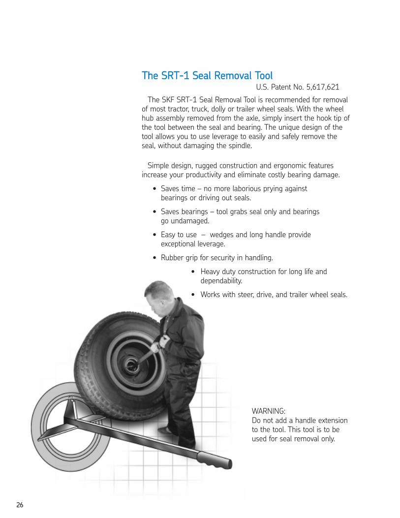
WARNING:
Do not add a handle extension
to the tool. This tool is to be
used for seal removal only.
TThhee SSRRTT--11 SSeeaall RReemmoovvaall TTooooll
Simple design, rugged construction and ergonomic features
increase your productivity and eliminate costly bearing damage.
• Saves time – no more laborious prying against
bearings or driving out seals.
• Saves bearings – tool grabs seal only and bearings
go undamaged.
• Easy to use – wedges and long handle provide
exceptional leverage.
• Rubber grip for security in handling.
• Heavy duty construction for long life and
dependability.
• Works with steer, drive, and trailer wheel seals.
The SKF SRT-1 Seal Removal Tool is recommended for removal
of most tractor, truck, dolly or trailer wheel seals. With the wheel
hub assembly removed from the axle, simply insert the hook tip of
the tool between the seal and bearing. The unique design of the
tool allows you to use leverage to easily and safely remove the
seal, without damaging the spindle.
U.S. Patent No. 5,617,621
2604293 TFO Self Study Guide_V3 12/1/06 9:50 AM Page 26
2277
44
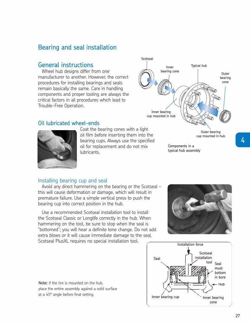
GGeenneerraall iinnssttrruuccttiioonnssWheel hub designs differ from one
manufacturer to another. However, the correct
procedures for installing bearings and seals
remain basically the same. Care in handling
components and proper tooling are always the
critical factors in all procedures which lead to
Trouble-Free Operation.
BBeeaarriinngg aanndd sseeaall iinnssttaallllaattiioonn
OOuutteerr bbeeaarriinngg
ccuupp mmoouunntteedd iinn hhuubb
CCoommppoonneennttss iinn aa
ttyyppiiccaall hhuubb aasssseemmbbllyy
Installing bearing cup and sealAvoid any direct hammering on the bearing or the Scotseal –
this will cause deformation or damage, which will result in
premature failure. Use a simple vertical press to push the
bearing cup into correct position in the hub.
Use a recommended Scotseal installation tool to install
the Scotseal Classic or Longlife correctly in the hub. When
hammering on the tool, be sure to stop when the seal is
“bottomed”; you will hear a definite tone change. Do not add
extra blows or it will cause immediate damage to the seal.
Scotseal PlusXL requires no special installation tool.
TTyyppiiccaall hhuubb
SSccoottsseeaall
IInnnneerr
bbeeaarriinngg ccoonneeOOuutteerr
bbeeaarriinngg
ccoonnee
IInnnneerr bbeeaarriinngg
ccuupp mmoouunntteedd iinn hhuubb
NNoottee:: if the tire is mounted on the hub,
place the entire assembly against a solid surface
at a 45° angle before final setting.
OOiill lluubbrriiccaatteedd wwhheeeell--eennddssCoat the bearing cones with a light
oil film before inserting them into the
bearing cups. Always use the specified
oil for replacement and do not mix
lubricants.
IInnssttaallllaattiioonn ffoorrccee
SSccoottsseeaall
iinnssttaallllaattiioonn
ttooooll
IInnnneerr bbeeaarriinngg
ccoonnee
HHuubb
SSeeaall
SSeeaall
mmuusstt
bboottttoomm
iinn bboorree
IInnnneerr bbeeaarriinngg ccuupp
2604293 TFO Self Study Guide_V3 12/1/06 9:50 AM Page 27

2288
CCaauuttiioonn:: Do not install the Scotseal® directly onto the spindle.
Place the hub (wheel) assembly against a solid surface or bench at a 45° angle for seal installation.
This aids in centering the bearing and seal in the hub bore. Clean bore of any particles, rust or grease.
1. Pre-lube the inner bearing cone with the lubricant that is being retained and place it into the hub.
2. Place the Scotseal® Classic or Scotseal® Longlife into the hub bore and insert the tool assembly
with centering plug into the seal. Note: Be sure to wear proper eye protection.
3. Hold the tool handle firmly and straight, and drive the seal with firm hammer strokes until the
seal is squarely seated. Continue driving the seal into the hub until the sound of impact changes.
4. After the seal is bottomed in the bore, check for freedom of movement by manually moving the
packing of the seal up and down. Ensure that the inner bearing rotates freely.
CCaauuttiioonn:: Install a new seal if the seal is cocked or damaged during or after installation.
1. 2. 3. 4.
PPrreessss tthhee sseeaall iinnttoo tthhee bboorree eevveennllyy bbyy hhaanndd..
LLiigghhttllyy lluubbrriiccaattee tthhee OODD
aanndd IIDD wwiitthh tthhee fflluuiidd bbeeiinngg
rreettaaiinneedd..
AA rruubbbbeerr mmaalllleett
mmaayy bbee uusseedd ttoo
ttaapp iinnttoo ppllaaccee..
TThhiiss sseeaall iiss hhaanndd iinnssttaallllaabbllee.. NNoo ssppeecciiaall ttoooollss aarree rreeqquuiirreedd..
IInnssttaallllaattiioonn pprroocceedduurreess:: SSccoottsseeaall®® PPlluussXXLL
CCaauuttiioonn:: Do not install the Scotseal® PlusXL
directly onto the spindle.
Place the hub (wheel) assembly flat or at least a 45°
angle for seal installation.
1. Pre-lube the inner bearing cone with the lubricant
that is being retained and place it into the hub.
2. Lightly lubricate the seal O.D. and I.D. evenly with the
fluid that is being retained. Also apply a thin layer of oil
on the hub bore that the seal is being pressed into.
NNEEVVEERR IINNSSTTAALLLL DDRRYY..
3. Press the seal by hand evenly into the bore. A rubber
mallet or other soft-faced tool may be used to gently tap
the seal into place. Be sure that the seal is evenly seated
and bottomed in the bore. As in any seal installation,
apply an even driving force to avoid cocking the seal
or damaging the flange surface.
4. Allow seal to set for about 5 minutes prior to installing
hub assembly onto spindle.
CCaauuttiioonn:: Install a new seal if the seal is cocked or damaged during or after installation.
IInnssttaallllaattiioonn pprroocceedduurreess:: SSccoottsseeaall®® CCllaassssiicc // SSccoottsseeaall®® LLoonngglliiffee
2604293 TFO Self Study Guide_V3 12/1/06 9:50 AM Page 28

2299
44
TThhee SSccoottsseeaall®® TToooollbbooaarrdd
• Keeps tools orderly and lessens
chances of tools being misplaced
or damaged
• Sturdy metal construction –
mounts easily on shop wall
• Fitting chart included
• Just order Part No. TB-1
IInnssttaallllaattiioonn ttoooolliinngg:: SSccoottsseeaall®® CCllaassssiicc // SSccoottsseeaall®® LLoonngglliiffee
BBEEAARRIINNGGCCOONNEE NNOO..
495AX497 539
555S 557A559 560 567 568 575 580 582 593 594
594A595 596 598
598A639 641 659 663
663A664 665
665A68lA683 687
CCEENNTTEERRIINNGGPPLLUUGG NNOO..
708 711 701 702 703 704 706 707 731 708 710 710 712 715 715 710 711 714 714 704 706 708 710 710 732 711 711 714 715 718
BBEEAARRIINNGGCCOONNEE NNOO..
749 749A749S 756A758 759 760 776 780
3778 3982 3984 4595 55575760 6379 6386
6386A6389 6461
6461A6559 6580
28995 33281 33287 33895 39578 39580 39581
CCEENNTTEERRIINNGGPPLLUUGG NNOO..
719 710 719 709 711 712 717 715 718 730 704 706 701 721708705706706706708708710712703716707701701702702
BBEEAARRIINNGGCCOONNEE NNOO..
39585 42688 45284 45285 47678 47685 47686 47687 52400 52401
JH217249JM205149 AJM207049 AJM511946JM716649JM718149JM719149HM212044HM212046HM212047
HM212049 XHM212049HM215249HM218248HM516449HM518445H715345
CCEENNTTEERRIINNGGPPLLUUGG NNOO..
704708700700708710710710718718719722723724719713733703704704706706707713710712716
Chart B
MATCHUP OF BEARING CONES & CENTERING PLUGS
TTooooll sseelleeccttiioonnSKF Scotseal® Classic and Scotseal® Longlife are to be installed using only SKF
Scotseal® installation tools. (See Chart A below)
CCeenntteerriinngg tthhee sseeaallPrecisely matched centering plugs are engineered to fit within the
inside diameter of the inner bearing cone and allow accurate centering
of the Scotseal in the bore of the hub, as well as preventing cocking
of the seal. Chart B below provides correct matchup of bearing
cone and centering plug.
SSttaannddaarrdd ttooooll hhaannddllee ((##445500223377))
SSeeaall DDrriivvee PPllaattee(These components are
interchangeable. See chart
below)
SSttaannddaarrdd PPlluugg BBuusshhiinngg
CCeenntteerriinngg
PPlluugg
WWaasshheerr
NNuutt
Chart ADRIVE PLATES & SEAL MATCHUPS
(Drive plates in bold numbers with matching seal numbers)
4273438736274362853635836365
42831175312443126431266312813130732470
435476904769347696476974769848000
436349753500035001350603506635072350753510235103
4414008640090
445393803942039425425504267242800
44643860438654387546390474834829748298486904879248794487964888450124
448387093998839990
44947686
451463054630646308
45242623426244263042631
453501905266052664
4574004040136401394014640147
46145152451604516245163
4623874738750387803878238783
46327438287582882028832
46543752437644376543800
47239380(w/disc
brks.)
47452658
48444922449644501045099451004510345108
45073742625
2604293 TFO Self Study Guide_V3 12/1/06 9:50 AM Page 29

3300
IInnssttaalllliinngg hhuubb aasssseemmbbllyy
DDOO NNOOTT AATTTTEEMMPPTT TTOO IINNSSTTAALLLLTTHHEE HHUUBB AASSSSEEMMBBLLYY BBYY HHAANNDD!!
Whether the hub is with or without the tire, do not install it
without mechanical support.
1. WWhheenn iinnssttaalllliinngg tthhee hhuubb aasssseemmbbllyy over the axle
spindle, be sure to align the hub bore to the center
of the spindle. Mechanical supports will allow you
to do this without scraping or otherwise damaging
the spindle, the threads, and in particular the seal.
2. IInnssttaallll tthhee oouutteerr bbeeaarriinngg ccoonnee aanndd aaddjjuussttiinngg nnuutt..
Tighten nut only until it is snug against the bearing
cone. DO NOT USE A PNEUMATIC TOOL during
this part of the procedure. Be sure to maintain
support of the hub assembly until the adjusting nut
is secure. Failure to do so may cause damage to
the seal and subsequent leakage of lubricant.
3. RReemmoovvee tthhee hhuubb ssuuppppoorrtt so that the hub is
resting on the bearings. Check for free rotation
of the bearings. Never allow hub to rest on seal.
4. FFoollllooww wwhheeeell bbeeaarriinngg aaddjjuussttmmeenntt as
instructed on following page.
AAxxllee ssppiinnddllee
((sshhaafftt))
2604293 TFO Self Study Guide_V3 12/1/06 9:50 AM Page 30

3311
44
WWhheeeell bbeeaarriinngg aanndd eenndd ppllaayy aaddjjuussttmmeenntt pprroocceedduurreess
SSTTEEPP 11:: LLuubbrriiccaattee tthhee wwhheeeell bbeeaarriinngg wwiitthh cclleeaann aaxxllee lluubbrriiccaanntt ooff tthhee ssaammee ttyyppee uusseedd iinn tthhee aaxxllee ssuummpp oorr hhuubb aasssseemmbbllyy..NNoottee:: NNeevveerr uussee aann iimmppaacctt wwrreenncchh wwhheenn ttiigghhtteenniinngg oorr lloooosseenniinngg lluugg nnuuttss oorr bboollttss dduurriinngg tthhee pprroocceedduurree..
IINNIITTIIAALL IINNIITTIIAALL FFIINNAALL BBAACCKK OOFFFF JJAAMM NNUUTT TTOORRQQUUEE AACCCCEEPPTTAABBLLEEAADDJJUUSSTTIINNGG BBAACCKK OOFFFF AADDJJUUSSTTIINNGG EENNDD PPLLAAYYNNUUTT TTOORRQQUUEE NNUUTT TTOORRQQUUEE AAXXLLEE TTYYPPEE TTHHRREEAADDSS FFIINNAALL NNUUTT SSIIZZEE TTOORRQQUUEE
PPEERR IINNCCHH BBAACCKK OOFFFF SSPPEECCIIFFIICCAATTIIOONNSS
SSTTEEPP 22 SSTTEEPP 33 SSTTEEPP 44 SSTTEEPP 55 SSTTEEPP 66 SSTTEEPP 77 SSTTEEPP 88
1122 11//66 TTUURRNN **
1188 11//44 TTUURRNN **
114411//22 TTUURRNN
1188
1122DDRRIIVVEE 11//44 TTUURRNN
1166
1122TTRRAAIILLEERR 11//44 TTUURRNN
1166
220000 llbb••fftt((227711 NN••mm))
WWHHIILLEERROOTTAATTIINNGGWWHHEEEELLSS
5500 llbb••fftt((6688 NN••mm))WWHHIILLEE
RROOTTAATTIINNGGWWHHEEEELLSS
SSTTEEEERR((FFRROONNTT))
NNOONN--DDRRIIVVEE
IINNSSTTAALLLL CCOOTTTTEERR PPIINN TTOO LLOOCCKK AAXXLLEENNUUTT IINN PPOOSSIITTIIOONN
..000011""--
..000055""((..002255mmmm--..112277mmmm))
AASS MMEEAASSUURREEDDPPEERR
PPRROOCCEEDDUURREE WWIITTHHDDIIAALL IINNDDIICCAATTOORR
WWHHEEEELL BBEEAARRIINNGG AADDJJUUSSTTMMEENNTT PPRROOCCEEDDUURREE
LLEESSSS TTHHAANN22 55//88""((6666..77mmmm))
22 55//88""((6666..77mmmm))aanndd oovveerr
DDOOWWEELL TTYYPPEEWWAASSHHEERR
TTAANNGG TTYYPPEEWWAASSHHEERR****
220000--330000 llbb••fftt((227711--440077 NN••mm))
330000--440000 llbb••fftt((440077--554422 NN••mm))
330000--440000 llbb••fftt((440077--554422 NN••mm))
220000--227755 llbb••fftt((227711--337733 NN••mm))
OONNEE FFUULLLLTTUURRNN
** IIff ddoowweell ppiinn aanndd wwaasshheerr ((oorr wwaasshheerr ttaanngg aanndd nnuutt ffllaatt)) aarree nnoott aalliiggnneedd,, rreemmoovvee tthhee wwaasshheerr,, ttuurrnn iitt oovveerr,, aanndd rreeiinnssttaallll.. IIff rreeqquuiirreedd,, lloooosseenn tthhee iinnnneerr ((aaddjjuussttiinngg)) nnuutt jjuusstt eennoouugghh ffoorr aalliiggnnmmeenntt..
**** BBeennddaabbllee ttyyppee wwaasshheerr lloocckk oonnllyy:: SSeeccuurree nnuuttss bbyy bbeennddiinngg oonnee wwhheeeell nnuutt wwaasshheerr ttaanngg oovveerr tthhee iinnnneerraanndd oouutteerr nnuutt.. BBeenndd tthhee ttaannggss oovveerr tthhee cclloosseesstt ffllaatt ppeerrppeennddiiccuullaarr ttoo tthhee hhaanngg..
PPrriinntteedd wwiitthh ppeerrmmiissssiioonn ooff tthhee TTMMCC,, RReeffeerreennccee RRPP661188
2604293 TFO Self Study Guide_V3 12/1/06 9:50 AM Page 31
3322
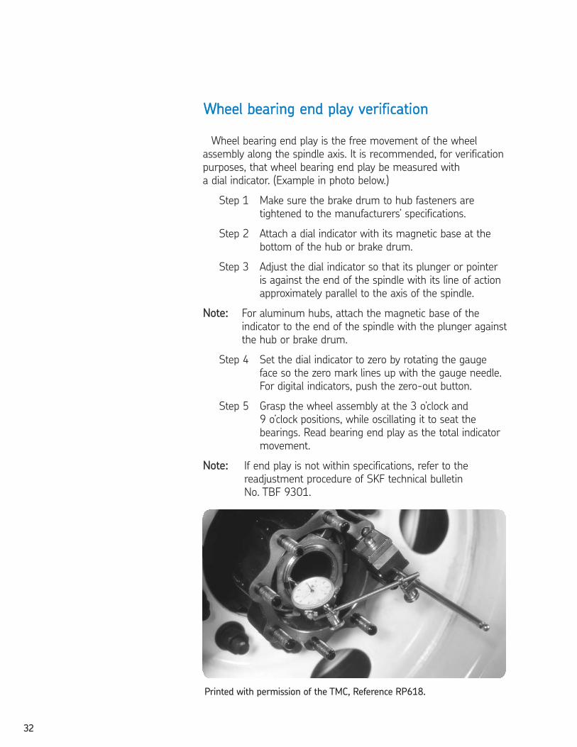
Wheel bearing end play is the free movement of the wheel
assembly along the spindle axis. It is recommended, for verification
purposes, that wheel bearing end play be measured with
a dial indicator. (Example in photo below.)
Step 1 Make sure the brake drum to hub fasteners are
tightened to the manufacturers’ specifications.
Step 2 Attach a dial indicator with its magnetic base at the
bottom of the hub or brake drum.
Step 3 Adjust the dial indicator so that its plunger or pointer
is against the end of the spindle with its line of action
approximately parallel to the axis of the spindle.
NNoottee:: For aluminum hubs, attach the magnetic base of the
indicator to the end of the spindle with the plunger against
the hub or brake drum.
Step 4 Set the dial indicator to zero by rotating the gauge
face so the zero mark lines up with the gauge needle.
For digital indicators, push the zero-out button.
Step 5 Grasp the wheel assembly at the 3 o’clock and
9 o’clock positions, while oscillating it to seat the
bearings. Read bearing end play as the total indicator
movement.
NNoottee:: If end play is not within specifications, refer to the
readjustment procedure of SKF technical bulletin
No. TBF 9301.
WWhheeeell bbeeaarriinngg eenndd ppllaayy vveerriiffiiccaattiioonn
Printed with permission of the TMC, Reference RP618.
2604293 TFO Self Study Guide_V3 12/1/06 9:50 AM Page 32
3333
44
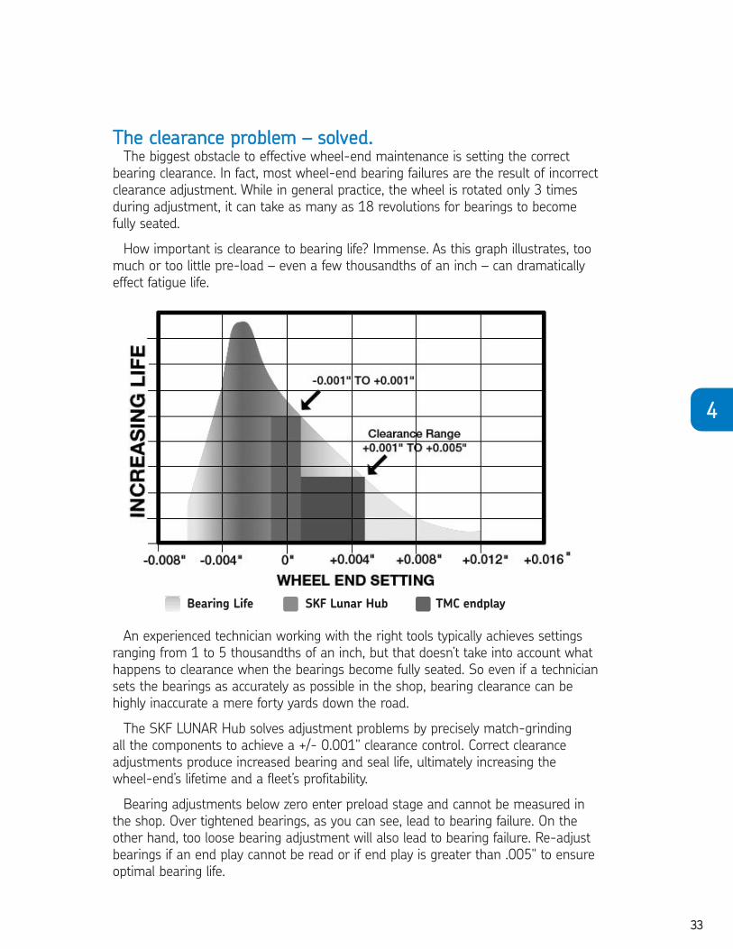
TThhee cclleeaarraannccee pprroobblleemm –– ssoollvveedd..The biggest obstacle to effective wheel-end maintenance is setting the correct
bearing clearance. In fact, most wheel-end bearing failures are the result of incorrect
clearance adjustment. While in general practice, the wheel is rotated only 3 times
during adjustment, it can take as many as 18 revolutions for bearings to become
fully seated.
How important is clearance to bearing life? Immense. As this graph illustrates, too
much or too little pre-load – even a few thousandths of an inch – can dramatically
effect fatigue life.
An experienced technician working with the right tools typically achieves settings
ranging from 1 to 5 thousandths of an inch, but that doesn’t take into account what
happens to clearance when the bearings become fully seated. So even if a technician
sets the bearings as accurately as possible in the shop, bearing clearance can be
highly inaccurate a mere forty yards down the road.
The SKF LUNAR Hub solves adjustment problems by precisely match-grinding
all the components to achieve a +/- 0.001" clearance control. Correct clearance
adjustments produce increased bearing and seal life, ultimately increasing the
wheel-end’s lifetime and a fleet’s profitability.
Bearing adjustments below zero enter preload stage and cannot be measured in
the shop. Over tightened bearings, as you can see, lead to bearing failure. On the
other hand, too loose bearing adjustment will also lead to bearing failure. Re-adjust
bearings if an end play cannot be read or if end play is greater than .005" to ensure
optimal bearing life.
Bearing Life SKF Lunar Hub TMC endplay
2604293 TFO Self Study Guide_V3 12/1/06 9:50 AM Page 33

3344
PPrroocceedduurree1. Hub mating surface must be free of dirt, burrs
and radial score lines.
2. Hub mating surface, hubcap flange and gasket should not be
greased or oiled.
3. Always install and re-install a hubcap with a
new gasket.
4. When using a Tamper Proof system with
synthetic grease, never fill hubcap with oil.
BBoolltt oonn hhuubbccaappss• Lockwashers of the split, conical or internal
toothed design may be used in conjunction with
the fastening bolts. Do not use flat washers.
• Thread all bolts loosely, then tighten down
bolts uniformly in a star pattern per the following
recommended torque values:
TTFF ((ZZyytteell)) HHuubbccaapp wwiitthh
eemmbbeeddddeedd mmeettaall rriinngg 1122--1166 llbbss..//fftt..
SSttaammppeedd SStteeeell HHuubbccaappss 1100--1144 llbbss..//fftt..
PPllaassttiicc HHuubbccaapp wwiitthh
eexxtteerrnnaall mmeettaall rriinngg 66--1100 llbbss..//fftt..
TThhrreeaaddeedd hhuubbccaappss• Lightly lubricate the threads of the hubcap and the O-ring,
with the lubricant that is being retained.
• Install the O-ring onto the hubcap.
• Install the hubcap assembly onto the hub.
• Using an 8-point 4 13/16" opening x 4 1/4" high socket,
torque to the following recommended values:
LLeexxaann 6600--7700 llbbss..//fftt..
HHuubbccaapp iinnssttaallllaattiioonn pprroocceedduurree
2604293 TFO Self Study Guide_V3 12/1/06 9:50 AM Page 34
3355
OOiill ffiillll
TThhrroouugghh cceenntteerr ffiillll ppoorrtt• Fill wheel end assembly through centerfill port with the
specified grade of oil. Wheel hub configurations vary,
allowing different amounts of oil to be added depending
on design. Allow for the oil to seep through the outer
bearing and fill the hub cavity. Continue to add oil until
the oil reaches the oil level fill line as indicated on the
hubcap.
• Install center fill hubcap plug.
TThhrroouugghh ssiiddee ffiillll ppoorrtt• Fill wheel end assembly through side fill port with
the specified grade of oil. Wheel hub configurations
vary, allowing different amounts of oil to be added
depending on design. Allow for the oil to seep through
the outer bearing and fill the hub cavity. During this fill
operation, DDOO NNOOTT AALLLLOOWW TTHHEE OOIILL TTOO GGOO AABBOOVVEE
TTHHEE CCEENNTTEERRLLIINNEE OORR WWEEEEPP HHOOLLEE.. This may result in
a weeping condition that may be perceived as a leaking
hubcap. Continue to add oil until the oil reaches the oil
level line as indicated on the hubcap.
• Install side fill hubcap plug per the following
recommended torque values:
33//88" -- 1188 NNPPTT
PPiippee PPlluugg 110000--114400 llbbss..//iinn..
33//44" -- 1166 UUNNFF ((ZZyytteell))
SSiiddee FFiillll PPlluugg 1155--2255 llbbss..//iinn..
Clean up any overspills that would
give the appearance of a leaky hubcap.
GGrreeaassee ffiillll:: SSeeee TTMMCC RRPP663311“Recommendations for Wheel End Lubrication”
and the vehicle manufacturer’s recommendation
for proper fill procedure.
44
2604293 TFO Self Study Guide_V3 12/1/06 9:50 AM Page 35
3366
CHAPTER 4 REVIEWTo take this test, simply place a card or sheet of paper under
the first question. After you’ve read it (and answered it to your-
self), slide the paper down below the next question. The correct
answer to the first problem will appear directly to the right of
the new question. Be sure not to skip any of the questions. This
learning technique assures more than four times the normal
retention rate for even this technical subject.
1. The SKF SRT-1 Seal removal tool is recommended forremoval of seals in____________.
❏ a. Tractors❏ b. Trucks❏ c. Trailers❏ d. All of the above
1. D2. The SKF SRT-1 saves bearings by grabbing
the____________.❏ a. Bearings❏ b. Seals❏ c. Bearings and seals❏ d. None of the above
2. B3. The Scotseal® PlusXL should not be installed directly on the
____________.❏ a. bearing❏ b. hub❏ c. spindle❏ d. none of the above
3. C4. Over tightened bearings, can lead to ____________.
❏ a. Bearing failure❏ b. Increased bearing life❏ c. Increased seal life❏ d. Non of the above
4. A
2604293 TFO Self Study Guide_V3 12/1/06 9:50 AM Page 36

3377
44
5. Correct procedures for installing bearings and seals remainsbasically the same for all hub manufacturers.
❏ True ❏ False5. T
6. Direct hammering on a bearing or Scotseal will cause premature wheel end failure.
❏ True ❏ False6. T
7. Changing the seal is always a permanent solution for wheelend leakage.
❏ True ❏ False7. F
8. The biggest obstacle to effective wheel-end maintenance is setting the correct bearing clearance.
❏ True ❏ False8. T
9. Always install and re-install a hubcap with a new gasket.❏ True ❏ False
9. T10. Faulty installation is one of the most common reasons a
seal fails.❏ True ❏ False
10. T
2604293 TFO Self Study Guide_V3 12/1/06 9:50 AM Page 37
3388
CHAPTER 5WHEEL END GREASE SEALS
In this chapter, you will find instructions for installing grease
seals on axles. Scotseals are needed for oil bath wheel ends.
First, you must replace the seal whenever you pull the wheel.
The old seal will most likely be nicked or bent when the
wheel was removed. Some of the seal’s press fit in the hub
will have been lost during removal of the bearing. The seal will
not fit as tight as it should which will prevent it from retaining
lube and excluding dirt. Reusing an old seal can cause costly
problems such as failure of the wheel bearing or brake lining.
Before discarding the old seal, check it for damage. This will
be explained in Chapter 8. Then proceed with the following
guidelines for seal installation.
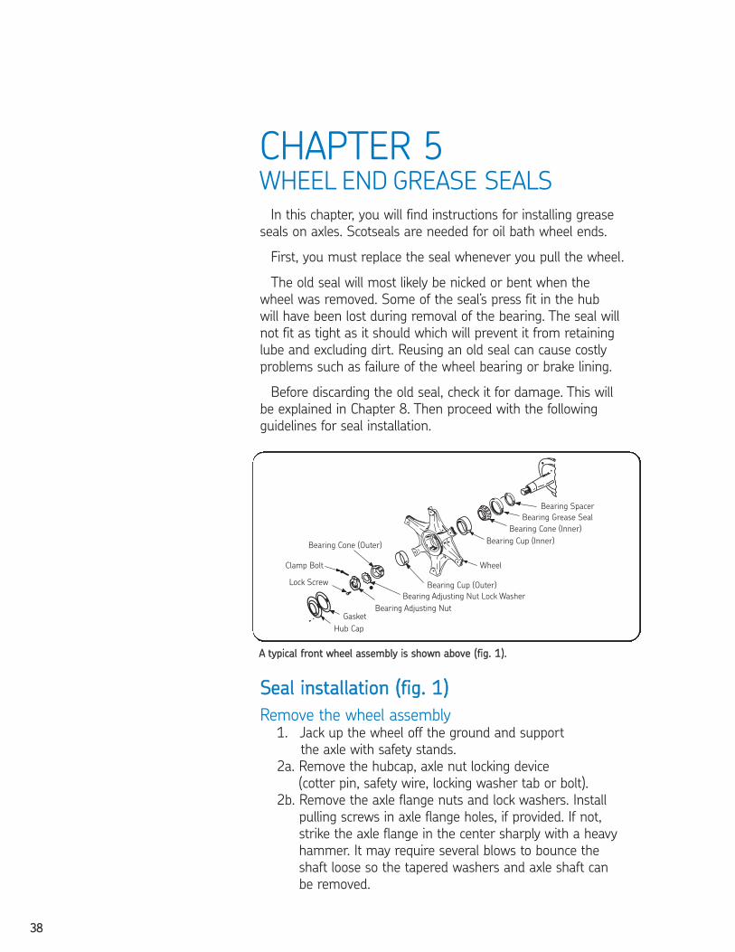
SSeeaall iinnssttaallllaattiioonn ((ffiigg.. 11))
Remove the wheel assembly1. Jack up the wheel off the ground and support
the axle with safety stands.
2a. Remove the hubcap, axle nut locking device
(cotter pin, safety wire, locking washer tab or bolt).
2b. Remove the axle flange nuts and lock washers. Install
pulling screws in axle flange holes, if provided. If not,
strike the axle flange in the center sharply with a heavy
hammer. It may require several blows to bounce the
shaft loose so the tapered washers and axle shaft can
be removed.
AA ttyyppiiccaall ffrroonntt wwhheeeell aasssseemmbbllyy iiss sshhoowwnn aabboovvee ((ffiigg.. 11))..
2604293 TFO Self Study Guide_V3 12/1/06 9:50 AM Page 38
3399
55
3. Remove the locking nut, adjusting nut, lock washer
and outer bearing cone. Since the arrangement and
design of washers, locks and nuts is different with each
manufacturer, be sure to note the order in which they
should be replaced after the seal is installed.
4. Slide the wheel and hub assembly off the spindle. Be
careful not to drag the inner bearing over the spindle
thread. If possible chain the wheel to the dolly for safety.
5. Remove the bearing spacer and pin from the spindle. Pry
out the old seal with a rolling head pry bar. Using a drift
to drive the bearing and seal out can damage the bearing
cage.
6. Remove the inner bearing cone. Record the worn seal’s
part number so you can refer to it when selecting the
new seal replacement.
7. If pulling more than one wheel, be sure to keep all of the
parts of each wheel assembly together and separate from
the other wheels.
Cleaning and inspection1. Clean the hub cavity and cap, removing all old lubricant.
Use a brush to clean the drum and brake mechanism.
Wipe the spindle clean.
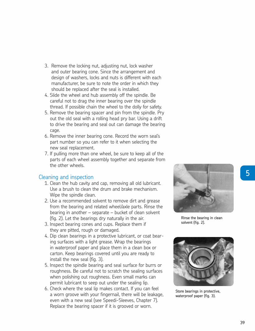
2. Use a recommended solvent to remove dirt and grease
from the bearing and related wheel/axle parts. Rinse the
bearing in another – separate – bucket of clean solvent
(fig. 2). Let the bearings dry naturally in the air.
3. Inspect bearing cones and cups. Replace them if
they are pitted, rough or damaged.
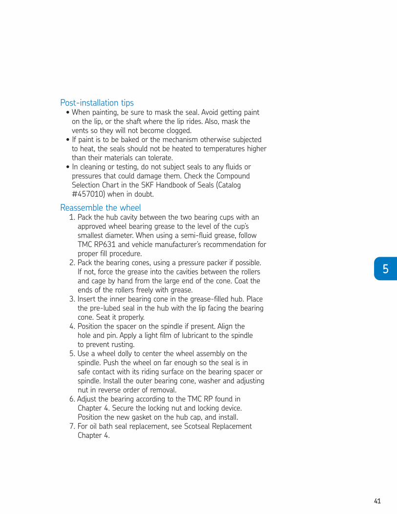
4. Dip clean bearings in a protective lubricant, or coat bear-
ing surfaces with a light grease. Wrap the bearings
in waterproof paper and place them in a clean box or
carton. Keep bearings covered until you are ready to
install the new seal (fig. 3).
5. Inspect the spindle bearing and seal surface for burrs or
roughness. Be careful not to scratch the sealing surfaces
when polishing out roughness. Even small marks can
permit lubricant to seep out under the sealing lip.
6. Check where the seal lip makes contact. If you can feel
a worn groove with your fingernail, there will be leakage,
even with a new seal (see Speedi-Sleeves, Chapter 7).
Replace the bearing spacer if it is grooved or worn.
RRiinnssee tthhee bbeeaarriinngg iinn cclleeaann
ssoollvveenntt ((ffiigg.. 22))..
SSttoorree bbeeaarriinnggss iinn pprrootteeccttiivvee,,
wwaatteerrpprrooooff ppaappeerr ((ffiigg.. 33))..
2604293 TFO Self Study Guide_V3 12/1/06 9:50 AM Page 39

4400
Installation checklist1. CChheecckk tthhee bboorree.. The leading edge must be deburred. A rounded
corner or chamfer should be provided.
2. CChheecckk tthhee sshhaafftt.. Remove surface nicks, burrs, grooves and spiral
machine marks (machine lead).
3. CChheecckk tthhee sshhaafftt eenndd.. Remove burrs or sharp edges. The shaft end
should be chamfered in applications where the shaft enters the seal
against the sealing lip.
4. CChheecckk sspplliinneess aanndd kkeeyywwaayyss.. Sharp edges should be covered with a
lubricated assembly sleeve, shim stock or tape to protect the seal lip.
5. CChheecckk ddiimmeennssiioonnss.. Be sure shaft and bore diameters match those
specified for the seal selected.
6. CChheecckk ffoorr ppaarrttss iinntteerrffeerreennccee.. Watch out for other machine parts
that might rub against the seal and cause friction and damaging
heat.
7. CChheecckk tthhee sseeaall.. Damage may have occurred prior to installation.
A sealing lip that is turned back, cut or otherwise damaged should
be replaced.
8. CChheecckk sseeaall ddiirreeccttiioonn.. Make sure that the new seal faces in the same
direction as the original one. Generally, the lip faces the lubricant or
fluid to be retained.
9. UUssee tthhee ccoorrrreecctt iinnssttaallllaattiioonn ttooooll.. Press-fitting tools should have an
outside diameter approximately .010" smaller than the bore size. For
best results, the center of the tool should be open so that pressure is
applied only at the outer edge of the seal (fig. 4).
10. PPrree--lluubbrriiccaattee tthhee sseeaalliinngg eelleemmeenntt.. Before installation, wipe the
element with the lubricant being retained.
11. NNeevveerr hhaammmmeerr ddiirreeccttllyy oonn tthhee ssuurrffaaccee ooff tthhee sseeaall.. Use proper
driving force, such as a soft-face tool, arbor press, or soft workpiece
(wood). Apply force evenly around the outer edge to avoid cocking
the seal.
12. PPoossiittiioonn tthhee sseeaall pprrooppeerrllyy iinn tthhee hhoouussiinngg aanndd iinnssppeecctt ffoorr
aalliiggnnmmeenntt aanndd iinnssttaallllaattiioonn ddaammaaggee..
TThhee pprreessss--ffiittttiinngg ttooooll
sshhoouulldd bbee ..001100"" lleessss tthhaann
tthhee bboorree II..DD.. ((ffiigg.. 44))..
2604293 TFO Self Study Guide_V3 12/1/06 9:50 AM Page 40
4411
55
Post-installation tips• When painting, be sure to mask the seal. Avoid getting paint
on the lip, or the shaft where the lip rides. Also, mask the
vents so they will not become clogged.
• If paint is to be baked or the mechanism otherwise subjected
to heat, the seals should not be heated to temperatures higher
than their materials can tolerate.
• In cleaning or testing, do not subject seals to any fluids or
pressures that could damage them. Check the Compound
Selection Chart in the SKF Handbook of Seals (Catalog
#457010) when in doubt.
Reassemble the wheel1. Pack the hub cavity between the two bearing cups with an
approved wheel bearing grease to the level of the cup’s
smallest diameter. When using a semi-fluid grease, follow
TMC RP631 and vehicle manufacturer’s recommendation for
proper fill procedure.
2. Pack the bearing cones, using a pressure packer if possible.
If not, force the grease into the cavities between the rollers
and cage by hand from the large end of the cone. Coat the
ends of the rollers freely with grease.
3. Insert the inner bearing cone in the grease-filled hub. Place
the pre-lubed seal in the hub with the lip facing the bearing
cone. Seat it properly.
4. Position the spacer on the spindle if present. Align the
hole and pin. Apply a light film of lubricant to the spindle
to prevent rusting.
5. Use a wheel dolly to center the wheel assembly on the
spindle. Push the wheel on far enough so the seal is in
safe contact with its riding surface on the bearing spacer or
spindle. Install the outer bearing cone, washer and adjusting
nut in reverse order of removal.
6. Adjust the bearing according to the TMC RP found in
Chapter 4. Secure the locking nut and locking device.
Position the new gasket on the hub cap, and install.
7. For oil bath seal replacement, see Scotseal Replacement
Chapter 4.
2604293 TFO Self Study Guide_V3 12/1/06 9:50 AM Page 41
4422
To take this test, simply place a card or sheet of paper under the first question.
After you’ve read it (and answered it to yourself), slide the paper down below the
next question. The correct answer to the first problem will appear directly to the
right of the new question. Be sure not to skip any of the questions. This learning
technique assures more than four times the normal retention rate for even this
technical subject.
01. An old seal should be replaced whenever .❏ a. it has been nicked ❏ b. some of the press-fit in the hub is lost❏ c. it has been bent❏ d. the wheel is pulled from the vehicle
1. D02. Reusing an old seal can cause failure of the .
❏ a. wheel❏ b. brake lining❏ c. bearing❏ d. any of the above
2. D03. can damage the bearing cage.
❏ a. Prying out the old seal with a rolling head pry bar❏ b. Driving the bearing and seal out with a drift❏ c. Removing the inner bearing cone❏ d. All of the above
3. B04. Bearing cones and cups should be if they are pitted
or damaged.❏ a. lubricated❏ b. replaced❏ c. rotated❏ d. all of the above
4. B05. A light film of prevents rusting on the spindle.
❏ a. SKF Bore-Tite❏ b. lubricant❏ c. wax paper❏ d. powdered metal epoxy type filler
5. B 06. The press-fitting tool used in installation should be the bore I.D.
❏ a. .010" less than❏ b. .010" more than❏ c. .025" less than❏ d. equal to
6. A
CHAPTER 5 REVIEW
2604293 TFO Self Study Guide_V3 12/1/06 9:50 AM Page 42

4433
55
07. Edges of the keyway and spline should be covered with .❏ a. straight mineral oil❏ b. lubricated assembly sleeve❏ c. ordinary engine oil❏ d. SKF Bore-Tite
7. B 08. When you pull the wheel, change the seal.
❏ True ❏ False8. T
9. It is unnecessary to check the old seal for damage beforedumping it.
❏ True ❏ False9. F
10. Small scratches on the shaft can allow some lubricant to seepunder the sealing lip.
❏ True ❏ False10. T
11. Replace bearing cups and cones if they are pitted, roughor damaged.
❏ True ❏ False11. T
2604293 TFO Self Study Guide_V3 12/1/06 9:50 AM Page 43
4444
CHAPTER 6NON WHEEL-END SEALS
SKF seals have the lip material bonded to the metal shell
(case). The bonding prevents leakage between the sealing lip
and the shell, and it provides a longer lasting, more effective
seal. This is different from the process used for assembled
seals, in which assembly pressure is used to hold the lip in
place between the metal parts.
A wide variety of sealing element (lip) materials is available.
Each has its own unique characteristics. Selection should be
made on the basis of application, compatibility with lubricants
and fluids being retained, operating temperatures, and other
conditions.
SSyynntthheettiiccssToday, the most popular and widely used sealing materials
are synthetics. These include nitriles, polyacrylates, silicones and
fluoroelastomers (Viton*). Each material has its own advantages
and disadvantages.
Nitrile Nitrile is the most popular material for the major applications
today. It is actually a mixture of two basic synthetic rubbers,
Buna and acrylonitrile polymers. Different properties are
obtained by changing the percentage of each polymer used
in the mixture (or copolymer).
Nitrile has generally replaced leather as a sealing lip material.
AADDVVAANNTTAAGGEESS
+ Good oil/grease compatibility
+ Abrasion resistance
+ Good low temperature and swell characteristics
+ Good manufacturing qualities
+ Relatively low in cost
DDIISSAADDVVAANNTTAAGGEESS
- Lacks compatibility with synthetic oils such as phosphate
ester and Skydrol
- Not recommended with EP lubes at elevated temperatures
OOPPEERRAATTIINNGG RRAANNGGEE
Standard SKF seals with nitrile sealing lips are effective in
applications involving most mineral oils and greases in
temperatures ranging from -40º to 250ºF (-40˚ to 121˚C).
2604293 TFO Self Study Guide_V3 12/1/06 9:50 AM Page 44

4455
66
IIDDEENNTTIIFFIICCAATTIIOONN
Varies from gray-black to shiny jet black
SSUUBBSSTTIITTUUTTEE LLIIPP MMAATTEERRIIAALLSS
Polyacrylate, silicone or fluoroelastomer (See Seal
Substitutions, page 53).
Duratemp (HNBR)A special compound based on hydrogenated nitrile (HNBR) Duratemp
offers improved tensile strength and resistance to heat, abrasion,
hardening in hot oil, ozone and weathering effects. In some cases,
aerated oils can be a problem for HNBRs.
OOPPEERRAATTIINNGG RRAANNGGEE
Hydrogenated nitrile seals can be used from
–40° to 300°F (-40° to 149°C).
AADDVVAANNTTAAGGEESS
+ Tensile strength typically 50% higher than standard nitrile
+ Ozone and UV resistance considerably improved
+ Heat resistance increased 20% with less reduction in hardness
and elongation, especially in hot oil with additives
+ Better abrasion resistance (equal to Duralip)
LLIIMMIITTAATTIIOONNSS
- Decreased elasticity at cold temperatures
- Lower compression set resistance at cold temperatures
(but better than Viton)
- Should not be considered a universal replacement for Viton
especially considering attack by aerated lubricants and high
temperature physical properties such as compression set
IIDDEENNTTIIFFIICCAATTIIOONNVisually the same as standard nitrile
SSUUBBSSTTIITTUUTTEE MMAATTEERRIIAALLSSPolyacrylate, Duralip and LongLife elastomers
(depending on the applications)
2604293 TFO Self Study Guide_V3 12/1/06 9:50 AM Page 45
4466
DuralipDuralip is SKF’s special nitrile compound for extreme abrasion
resistance. It is recommended where scale, sand, grit, dirt or
other highly abrasive materials are present.
AADDVVAANNTTAAGGEESS
+ Extreme abrasion resistance
+ See nitrile
DDIISSAADDVVAANNTTAAGGEESS
- See nitrile
OOPPEERRAATTIINNGG RRAANNGGEE
See nitrile
IIDDEENNTTIIFFIICCAATTIIOONN
See nitrile
SSUUBBSSTTIITTUUTTEE LLIIPP MMAATTEERRIIAALLSS
See nitrile
PolyacrylatesPolyacrylates are elastomers that are compatible with higher
operating temperatures, as well as extreme pressure (EP)
lubricants. They are available in most general purpose designs.
AADDVVAANNTTAAGGEESS
+ Good compatibility with most oils, including EP lubricants
+ High resistance to oxidation and ozone
+ Better compatibility with higher operating temperatures
than nitrile
DDIISSAADDVVAANNTTAAGGEESS
- Low compatibility with water and some industrial fluids
- Poor compression-set characteristics
OOPPEERRAATTIINNGG RRAANNGGEE
Seals with polyacrylate lips are effective in temperatures
ranging from -40º to 300ºF (-40 to 149˚C).
2604293 TFO Self Study Guide_V3 12/1/06 9:50 AM Page 46
4477
66
IIDDEENNTTIIFFIICCAATTIIOONN
Generally black with same appearance as nitrile
SSUUBBSSTTIITTUUTTEE MMAATTEERRIIAALLSS
Nitrile, silicone or fluoroelastomer (See Seal Substitutions,
page 53).
SiliconeSilicone’s high lubricant absorbency minimizes friction and
wear. It can be used in a wide range of temperatures. Silicone
seals are made only in bonded designs.
AADDVVAANNTTAAGGEESS
+ High lubricant absorbency
+ Very flexible
+ Wide temperature range
DDIISSAADDVVAANNTTAAGGEESS
- Poor compatibility with oils that have become oxidized,
and EP lube additives
- Tendency to tear and cut during installation
- Poor abrasion resistance
- Relatively high cost
OOPPEERRAATTIINNGG RRAANNGGEE
Silicone seals can withstand a very wide temperature range,
from -100º to 325ºF (-73˚ to 163˚C).
IIDDEENNTTIIFFIICCAATTIIOONN
Generally red or orange, but sometimes gray or blue. Silicone
seals feel softer and are more flexible than other materials
SSUUBBSSTTIITTUUTTEE LLIIPP MMAATTEERRIIAALLSS
Fluoroelastomers, polyacrylate or nitrile (See Seal
Substitutions, page 53).
Fluoroelastomers (Viton) Fluoroelastomers are recommended for use with special
lubricants and chemicals which cannot be handled by nitrile,
polyacrylate or silicone. They are compatible with oils,
chemicals, fuels and lubricants over a broad range of
temperatures that are too extreme for other sealing elements.
2604293 TFO Self Study Guide_V3 12/1/06 9:50 AM Page 47

4488
Fluoroelastomers are available in standard line designs as
well as large diameter seals. One fluoroelastomer, Viton, is
compatible with aliphatic and aromatic hydrocarbons (carbon
tetrachlorine, benzene, toluene, xylene) that are used as
solvents for other rubbers.
Because of its compatibility with many different fluids over a
broad temperature range, Viton also is effective in aircraft and
space equipment applications.
AADDVVAANNTTAAGGEESS
+ Wide temperature range
+ Low swell characteristics
+ Compatible with lubes, additives and chemicals that destroy
other synthetic materials
+ Less downtime
+ Extreme abrasion resistance
DDIISSAADDVVAANNTTAAGGEESS
- Relatively high cost
OOPPEERRAATTIINNGG RRAANNGGEE
-40º to 400ºF (-40˚ to 204˚C)
IIDDEENNTTIIFFIICCAATTIIOONN
Brown to black; may also be blue or green
SSUUBBSSTTIITTUUTTEE LLIIPP MMAATTEERRIIAALLSS
(See Seal Substitutions, page 53)
OOtthheerr SSyynntthheettiiccssIn addition to these standard materials, SKF can supply seals
with elements molded of other materials for special conditions.
AADDVVAANNTTAAGGEESS
+ Excludes dirt and dust well
+ Retains grease efficiently
+ High lubricant absorbency
DDIISSAADDVVAANNTTAAGGEESS
- Cannot confine light oils
- May trap metal particles, causing shaft wear
- Absorbs water, which may cause shaft rusting
OOPPEERRAATTIINNGG RRAANNGGEE
-65º to 200ºF (-54 to 93˚C)
SSUUBBSSTTIITTUUTTEE LLIIPP MMAATTEERRIIAALLSS
Nitrile, polyacrylate or fluoroelastomer (See Seal
Substitutions, page 53).
2604293 TFO Self Study Guide_V3 12/1/06 9:50 AM Page 48
4499
66
FFeellttFelt is another non-synthetic material which has long been
used as a sealing material. Made of wool and sometimes
laminated with synthetic rubber washers, felt is generally
limited to light dirt exclusion. However, it effectively retains
heavy lubricants such as wheel bearing grease and performs
well in sparsely lubricated applications under some conditions
such as small electric motors. Felt washers are available only
in limited sizes.
AADDVVAANNTTAAGGEESS
+ Excludes dirt and dust well
+ Retains grease efficiently
+ High lubricant absorbency
DDIISSAADDVVAANNTTAAGGEESS
- Cannot confine light oils
- May trap metal particles, causing shaft wear
- Absorbs water, which may cause shaft rusting
OOPPEERRAATTIINNGG RRAANNGGEE
-65ºF to 200ºF
SSUUBBSSTTIITTUUTTEE LLIIPP MMAATTEERRIIAALLSS
Nitrile, polyacrylate or fluoroelastomer (See Seal
Substitutions, page 53).
CCoommppoouunndd SSeelleeccttiioonn CChhaarrttThe compatibility of sealing element materials with most
fluids currently used can be found in the Compound Selection
Chart in the SKF Handbook of Seals (Catalog #457010).
This chart rates the operation of different sealing materials
(minor effect, moderate effect, static only, not recommended,
insufficient data) within the range of specified operating
temperatures and conditions for most common lubricants,
fresh or salt water, and fluids.
Sealing Lip PerformanceFollowing is a description of the lip itself and how it works.
In this example, the Waveseal will be used. The Waveseal,
SKF’s preferred design, provides at least 30% more service
life than other radial lip seals. A number of the toughest fleet
applications specify this design to assure top performance
and increased service life.
2604293 TFO Self Study Guide_V3 12/1/06 9:50 AM Page 49
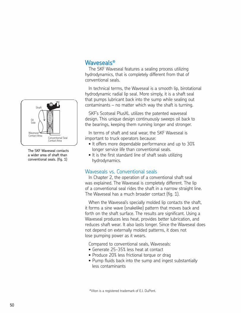
5500
WWaavveesseeaallss®®
The SKF Waveseal features a sealing process utilizing
hydrodynamics, that is completely different from that of
conventional seals.
In technical terms, the Waveseal is a smooth lip, birotational
hydrodynamic radial lip seal. More simply, it is a shaft seal
that pumps lubricant back into the sump while sealing out
contaminants – no matter which way the shaft is turning.
SKF’s Scotseal PlusXL utilizes the patented waveseal
design. This unique design continuously sweeps oil back to
the bearings, keeping them running longer and stronger.
In terms of shaft and seal wear, the SKF Waveseal is
important to truck operators because:
• It offers more dependable performance and up to 30%
longer service life than conventional seals.
• It is the first standard line of shaft seals utilizing
hydrodynamics.
Waveseals vs. Conventional sealsIn Chapter 2, the operation of a conventional shaft seal
was explained. The Waveseal is completely different. The lip
of a conventional seal rides the shaft in a narrow straight line.
The Waveseal has a much broader contact (fig. 1).
When the Waveseal’s specially molded lip contacts the shaft,
it forms a sine wave (snakelike) pattern that moves back and
forth on the shaft surface. The results are significant. Using a
Waveseal produces less heat, provides better lubrication, and
reduces shaft wear. It also lasts longer. Since the Waveseal does
not depend on externally molded patterns, it does not
lose pumping power as it wears.
Compared to conventional seals, Waveseals:
• Generate 25-35% less heat at contact
• Produce 20% less frictional torque or drag
• Pump fluids back into the sump and ingest substantially
less contaminants
TThhee SSKKFF WWaavveesseeaall ccoonnttaaccttss
aa wwiiddeerr aarreeaa ooff sshhaafftt tthhaann
ccoonnvveennttiioonnaall sseeaallss.. ((ffiigg.. 11))
*Viton is a registered trademark of E.I. DuPont.
2604293 TFO Self Study Guide_V3 12/1/06 9:50 AM Page 50
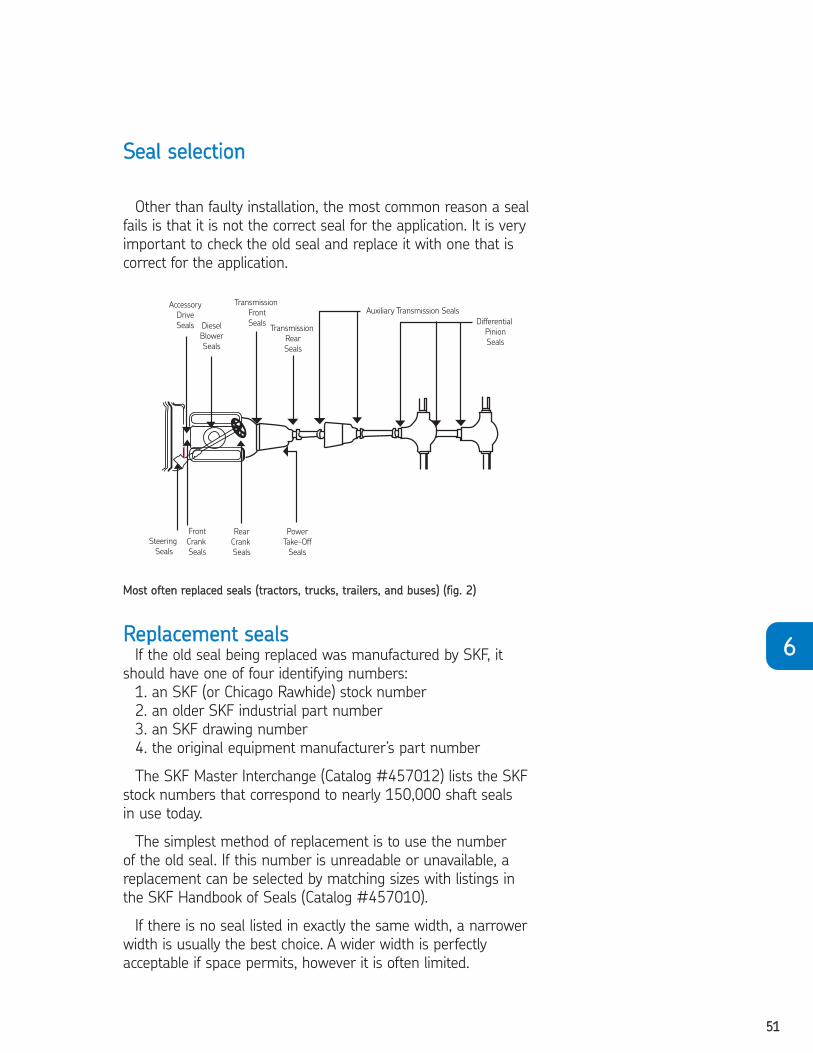
5511
66
SSeeaall sseelleeccttiioonn
Other than faulty installation, the most common reason a seal
fails is that it is not the correct seal for the application. It is very
important to check the old seal and replace it with one that is
correct for the application.
RReeppllaacceemmeenntt sseeaallssIf the old seal being replaced was manufactured by SKF, it
should have one of four identifying numbers:
1. an SKF (or Chicago Rawhide) stock number
2. an older SKF industrial part number
3. an SKF drawing number
4. the original equipment manufacturer’s part number
The SKF Master Interchange (Catalog #457012) lists the SKF
stock numbers that correspond to nearly 150,000 shaft seals
in use today.
The simplest method of replacement is to use the number
of the old seal. If this number is unreadable or unavailable, a
replacement can be selected by matching sizes with listings in
the SKF Handbook of Seals (Catalog #457010).
If there is no seal listed in exactly the same width, a narrower
width is usually the best choice. A wider width is perfectly
acceptable if space permits, however it is often limited.
MMoosstt oofftteenn rreeppllaacceedd sseeaallss ((ttrraaccttoorrss,, ttrruucckkss,, ttrraaiilleerrss,, aanndd bbuusseess)) ((ffiigg.. 22))
2604293 TFO Self Study Guide_V3 12/1/06 9:50 AM Page 51

5522
Other applicationsInstallation procedures for transmissions, pinions, prop shafts,
timing covers and other fleet seal applications are somewhat
similar, but with these precautions:
• Seals should be press-fitted with a press-fitting tool and
installation force should be applied as closely as possible to
the outside edge of the seal.
• If a seal is installed into the housing bore with the shaft
already installed, a sleeve-type or hollow fitting tool should
be used to protect the lip as it is fitted over the shaft.
• Seals have flexible sealing members smaller than the shafts
on which they function. When the shaft is assembled
through the back of the seal, no special precautions are
necessary other than removing nicks, burrs, and other
rough spots from the shaft. The shaft end should be
chamfered when it enters the seal against its lip.
• If the shaft is not tapered, or if a keyway or spline is
present, a thin-wall coned assembly is recommended.
Sharp spline and keyway edges should be covered with a
lubricated assembly sleeve, shim stock or tape to protect
the seal lip (fig.3).
AA ccoonneedd aasssseemmbbllyy sslleeeevvee
mmaayy bbee uusseedd ttoo pprrootteecctt tthhee
sseeaall lliipp ((ffiigg.. 33))..
2604293 TFO Self Study Guide_V3 12/1/06 9:50 AM Page 52

5533
66
SSeeaall ssuubbssttiittuuttiioonnssThe SKF Handbook of Seals (457010) lists different seal
designs which can be substituted for the old seal (within the
limits of the operating conditions). Seal materials and proper
substitutes were discussed throughout this chapter. Because
of the importance of knowing and understanding these
materials, they will be reviewed here.
If a lip material to match the old seal cannot be found
in the size listings, refer to the Substitute Material Table in
the Handbook of Seals. Some of the more common seal
substitutions are listed below.
• Nitrile instead of felt
• Nitrile instead of leather
• Polyacrylate instead of nitrile
• Fluoroelastomer instead of polyacrylate
• Fluoroelastomer instead of silicone
Remember, colors other than black usually mean special
materials. Materials should generally be substituted only if
immediate replacement is more important than the assurance
of maximum seal life. Because of the great number of factors
involved, it is not always true that a premium elastomer will do
a better sealing job than a less expensive material.
If the operating temperature is above 250ºF (121˚C), nitrile
seals substituted for polyacrylate or silicone may have a shorter
life. And, while silicone has a wider temperature range than
polyacrylate, it breaks down if it is exposed to oxidized oils.
SSeeaallss ffoorr nneeww aapppplliiccaattiioonnssChoosing the right seal for a particular application depends
on operating conditions:
1. Size
2. Speed
3. Pressure
4. Temperature/fluid compatibility
Each of these operating conditions should influence your
selection of a seal for that application.
2604293 TFO Self Study Guide_V3 12/1/06 9:50 AM Page 53

5544
SizeSeal dimensions (fig. 3) used in seal selection include:
Seal bore diameterThis is the diameter of the hole into which the seal will be
fitted.
Seal outside diameter (O.D.)The O.D. is the seal’s press-fit diameter. It is usually .004"
to .010" larger than the bore so the seal will be held firmly in
place.
Seal widthThis is the overall width (including the inner and outer shells).
Shaft diameterBecause the seal’s inside diameter is difficult to measure and
varies with seal designs, the shaft diameter for which the seal
was designed is used as the cataloged inside dimension.
Measuring the seal O.D.When measuring the seal’s outside diameter, measurements
should be taken in at least three places equally spaced around
the seal. The average of these readings can then be used as
the diameter.
How to measure seal I.D.If you don’t know the actual shaft diameter, you can estimate
it by measuring the seal’s inside dimensions.
It makes no difference if the seal has an inner shell or not.
Simply average the three measurements of the lip inside
diameter (fig. 4). Estimate shaft size as follows:
Estimated shaft diameter Add to lip I. D.
Up to 1" .031"
1" to 2" .021" – .047"
2" to 6" .047" – .063"
6" to 8" .063" – .094"
8" to 12" .125"
AA vveerrnniieerr iiss uusseedd ttoo
mmeeaassuurree tthhee sseeaall’’ss II..DD..
((ffiigg.. 44))
((ffiigg.. 33))
2604293 TFO Self Study Guide_V3 12/1/06 9:50 AM Page 54
5555
66
SSppeeeeddThe maximum speed at which a seal can operate depends
on other operating conditions. These conditions include shaft
finish, pressure, temperature, eccentricity, the lubricant or fluid
to be retained, and the particular design of the seal selected.
For instance, as shaft finish is improved (to the 10-20
micro-inch range) shaft speed can be increased. As shaft
eccentricity (run-out) is reduced, shaft speed can be increased.
Surface speed at the contact point between the seal and the
shaft (fpm: feet per minute) is generally a better indicator of
seal performance than revolutions per minute (rpm).
To convert rpm to fpm, use the following formula or refer
to the SKF Handbook of Seals (Catalog #457010).
..226622 xx rrppmm xx sshhaafftt ddiiaammeetteerr ((iinncchheess)) == ffppmm
PPrreessssuurreeThe next aspect important to proper seal selection is
pressure.
Allowable pressure goes down as shaft speed goes up.
The more pressure applied to a seal, the more lip surface
contacts the shaft. More contact produces more friction and
heat. Friction and heat rise as shaft speed increases. These
factors cause faster wear and can shorten seal life.
Many of the bonded designs in the SKF Handbook of Seals
can handle pressures of 15 psi at speeds up to 1,000 fpm.
These can be found in the Handbook’s table of operating condi-
tions.
When speeds increase past 1,000 fpm, some of these same
seals can handle only 5 psi.
2604293 TFO Self Study Guide_V3 12/1/06 9:50 AM Page 55
5566
TTeemmppeerraattuurree//fflluuiidd ccoommppaattiibbiilliittyyThe final consideration affecting seal selection is temperature
and fluid compatibility. Handbook listings are given in 16
“continuous” ratings – the relatively constant ambient
temperature next to the seal, or the temperature of the
lubricant it retains.
When operating conditions are under 0ºF (-18˚C) or above
200ºF (93˚C), the range recommended in the Handbook must
be considered in selecting the type of sealing element material.
As was earlier stated, SKF’s standard nitrile compound
provides good service in most sealing applications from -65º
to 250ºF (-54˚ to 121˚C). However, silicone, polyacrylate or
fluoroelastomers provide safer operating limits and are pre-
ferred with higher or lower temperatures.
SSuummmmaarryyThere are many factors involved in selecting seals. To
avoid confusion, the SKF Handbook of Seals contains a
Recommended Operating Conditions Selection Chart to
assure a correct seal choice.
All of the selection factors are grouped together along with
recommendations about the type of seal to use in almost every
application.
2604293 TFO Self Study Guide_V3 12/1/06 9:50 AM Page 56

5577
OOiill SSeeaall IInnssttaallllaattiioonn IInnssttrruuccttiioonnss
1. CChheecckk tthhee bboorree – The leading edge must be deburred.
A rounded comer or chamfer should be provided.
2. CChheecckk tthhee sshhaafftt – Remove surface nicks, burrs, grooves
and spiral machine marks (machine lead).
3. CChheecckk tthhee sshhaafftt eenndd – Remove burrs or sharp edges.
The shaft end should be chamfered in applications where
the shaft enters the seal against the sealing lip.
4. CChheecckk sspplliinneess aanndd kkeeyywwaayyss – Sharp edges should be
covered with a lubricated assembly sleeve, shim stock or
tape to protect the seal lip.
5. CChheecckk ddiimmeennssiioonnss – Be sure shaft and bore diameters
match those specified for the seal selected.
6. CChheecckk ffoorr ppaarrttss iinntteerrffeerreennccee – Watch out for other
machine parts that might rub against the seal and cause
friction and damaging heat.
7. CChheecckk tthhee sseeaall – Damage may have occurred
prior to installation. A sealing lip that is turned back, cut
or otherwise damages should be replaced.
8. CChheecckk sseeaall ddiirreeccttiioonn – Make sure that the new seal faces
in the same direction as the original one. Generally, the lip
faces the lubricant or fluid to be retained.
9. UUssee tthhee ccoorrrreecctt iinnssttaallllaattiioonn ttoooollss – Press fitting tools
should have an outside diameter approximately .010"
(.254 mm) smaller than the bore size. For best results,
the center of the tool should be open so that pressure is
applied only at the outer edge.
10. PPrree--lluubbrriiccaattee tthhee sseeaalliinngg eelleemmeenntt – Before installation,
wipe the element with the lubricant being retained.
11. NNeevveerr hhaammmmeerr ddiirreeccttllyy oonn tthhee ssuurrffaaccee ooff tthhee sseeaall –
Use proper driving force, such as a softface tool, arbor
press, or soft workplace (wood). Apply force evenly around
the outer edge to avoid cocking the seal.
1122.. PPoossiittiioonn tthhee sseeaall pprrooppeerrllyy iinn tthhee hhoouussiinngg aanndd iinnssppeecctt
ffoorr aalliiggnnmmeenntt aanndd iinnssttaallllaattiioonn ddaammaaggee..
66
2604293 TFO Self Study Guide_V3 12/1/06 9:50 AM Page 57
5588
CHAPTER 6 REVIEWTo take this test, simply place a card or sheet of paper under the first question.
After you’ve read it (and answered it to yourself), slide the paper down below the
next question. The correct answer to the first problem will appear directly to the
right of the new question. Be sure not to skip any of the questions. This learning
technique assures more than four times the normal retention rate for even this
technical subject.
01. SKF seals are available in a wide variety of sealing element materials and eachhas its own unique characteristics. Selection should be on the basis of .
❏ a. application ❏ b. compatibility with lubes and fluids ❏ c. operating temperature ❏ d. all of the above
1. D02. Nitrile has generally replaced as a sealing lip.
❏ a. felt❏ b. silicone❏ c. leather❏ d. Viton
2. C03. One of nitrile’s disadvantages is that it is not compatible with .
❏ a. oil❏ b. abrasion❏ c. synthetic oils❏ d. all of the above
3. C04. One of polyacrylate’s disadvantages is its .
❏ a. low compatibility with water and some industrial fluids❏ b. high resistance to oxidation and ozone❏ c. relatively high cost❏ d. good compression-set characteristics
4. A05. Silicone’s advantages include its .
❏ a. high lube absorbency❏ b. good flexibility❏ c. ability to handle a wide temperature range❏ d. all of the above
5. D6. Seals made of fluoroelastomers .
❏ a. are inexpensive ❏ b. sometimes require special molds ❏ c. lack wide temperature range resistance ❏ d. are compatible with aggressive oil
6. D
2604293 TFO Self Study Guide_V3 12/1/06 9:50 AM Page 58

5599
7. Felt is a non-synthetic material which has long been used as a sealing material. Its advantages include .
❏ a. excellent water resistance❏ b. good exclusion of dust and dirt❏ c. tends to smooth rough shaft surfaces❏ d. good oil retention
7. B08. Using a Waveseal produces significant results which include .
❏ a. less heat produced❏ b. less shaft wear❏ c. better lip lubrication❏ d. all of the above
8. D9. A replacement seal manufactured by SKF is identified by .
❏ a. an SKF stock number❏ b. an SKF drawing number❏ c. the original equipment manufacturer’s part number❏ d. any of the above
9. D10. Choosing the right seal for an application depends on .
❏ a. seal dimensions❏ b. speed and pressure❏ c. temperature❏ d. all of the above
10. D11. A substitute material for silicone is .
❏ a. felt❏ b. leather❏ c. nitrile❏ d. none of the above
11. C12. Nitrile seals will have shortened lifespans if the operating
temperature is 250ºF.❏ a. below❏ b. above❏ c. at❏ d. none of the above
12. B
66
2604293 TFO Self Study Guide_V3 12/1/06 9:50 AM Page 59
6600
13. is the seal’s press-fit diameter; usually .004" to .008" larger than the bore.
❏ a. Shaft diameter❏ b. Seal outside diameter❏ c. Seal inside diameter❏ d. Bore diameter
13. B14. The most popular and versatile sealing materials in use today are
synthetics, such as nitrites, polyacrylates, silicones and fluoroelastomers.❏ True ❏ False
14. T15. Nitrite is the most popular material for the majority of sealing
applications today.❏ True ❏ False
15. T16. One of Vitons disadvantages is its poor resistance to temperature extremes.
❏ True ❏ False16. F
17. Polyacrylates are elastomers that work well with high operatingtemperatures and EP lubricants.
❏ True ❏ False17. T
18. Polyacrylates have high resistance to water.❏ True ❏ False
18. F19. The lip of a Waveseal rides the shaft in a straight-line pattern.
❏ True ❏ False19. F
20. The maximum speed at which a seal can operate depends on other operatingconditions. These conditions include: .
❏ a. the design of the seal selected❏ b. the lubricant or fluid to be retained❏ c. pressure and temperature❏ d. all of the above
20. D21. A thin-wall coned assembly sleeve is recommended when .
❏ a. the shaft is not tapered❏ b. a keyway is discovered❏ c. a spline is present❏ d. all of the above
21. D
2604293 TFO Self Study Guide_V3 12/1/06 9:51 AM Page 60

6611
22. If the seal has no identification numbers, you should averagethree measurements of the .
❏ a. seal width❏ b. seal bore❏ c. lip inside diameter❏ d. any of the above
22. C23. A common reason for seal failure is that it is not the right seal
for the application in the first place.❏ True ❏ False
23. T24. If there is no seal listed in the exact same width in the SKF Handbook
of Seals, a narrower width seal may be used.❏ True ❏ False
24. T25. Substitutions should be used only when immediate use is more
important than the assurance of maximum seal life.❏ True ❏ False
25. T26. Using a seal with a premium elastomer lip will always do a better job
than a less expensive material.❏ True ❏ False
26. F27. Seal bore is the diameter of the hole into which the seal will be fitted.
❏ True ❏ False27. T
28. Seal width is the width of the inner shell only.❏ True ❏ False
28. F29. The outside diameter can be measured by taking one reading
around the seal.❏ True ❏ False
29. F30. If the actual shaft diameter is unknown, you can estimate the
shaft diameter by measuring the seal’s outside dimensions.❏ True ❏ False
30. F31. Use a sleeve-type or hollow fitting tool when installing a seal
into the housing bore of a pinion with the shaft already inserted.❏ True ❏ False
31. T32. Seals are press-fitted in transmissions by applying force as
close as possible to the inside edge of the seal.❏ True ❏ False
32. F
66
2604293 TFO Self Study Guide_V3 12/1/06 9:51 AM Page 61

6622
CHAPTER 7WEAR SLEEVES
Continuous contact between a rotating shaft and a seal always
causes shaft polishing friction. Under normal operating conditions,
the friction causes a slight wear track on the shaft.
But, as operating conditions worsen, shaft wear can accelerate.
Heat, dirt, excessive speed, lack of lubrication, eccentricity or a
cocked seal can produce a deep groove on the surface. The
ultimate result is a leak.
If this groove can be felt with a paper clip or with your finger
nail, it has become too deep to accommodate a replacement seal
without leaking.
There are three solutions:
1. Reworking or remetalizing the shaft surface at a machine
shop – High cost, requires hours of fleet downtime.
2. Replacing the shaft – Also expensive, with substantial fleet
downtime.
3. Installing a wear sleeve – Comparatively low in cost with
virtually no downtime.
When it comes to correcting yokes, flanges and shafts, a wear
sleeve requires the least amount of downtime and cost. Applied
over the damaged shaft, it makes the shaft usable again, elimi-
nates shaft leaks, and smooths out damaged surfaces – all faster
and less expensive than re-metalizing or replacing the shaft.
SKF offers one special type of wear sleeve designed for even
more efficient shaft repair – Speedi-Sleeves (fig. 1).
SSppeeeeddii--SSlleeeevveessSpeedi-Sleeves offer fleet operators a way to quickly repair
worn shaft surfaces right in the garage. Downtime is reduced
since installation takes only a few minutes, often without
removing the shaft.
There is no resizing of the seal. Unlike conventional thick
sleeves, Speedi-Sleeves use the original size seal. No matter
whether the Speedi-Sleeve is used on a crankshaft, transmission,
or pinion, both labor and hard parts inventory costs are
substantially reduced.
Speedi-Sleeves are precision-made of ultra-thin, stainless steel.
Once installed, it provides a new leakproof barrier and a long-
lasting wear surface for the new seal that can outlast the original
shaft finish.
TThhee SSppeeeeddii--SSlleeeevvee rreeppaaiirrss
ddaammaaggeedd sshhaaffttss eeffffiicciieennttllyy
((ffiigg.. 11))..
2604293 TFO Self Study Guide_V3 12/1/06 9:51 AM Page 62

6633
77
AADDVVAANNTTAAGGEESS
+ Corrects crankshaft, pinion, and transmission surfaces
+ Repairs yokes, flanges and shafts
+ Can be used without changing the seal size or part number
+ Requires little downtime
Each sleeve is built with a removable flange and includes
a special tool for installation. This tool is placed over the
Speedi-Sleeve. Both the tool and sleeve are tapped into
position on the shaft, yoke or flange.
The flange on the Speedi-Sleeve allows the sleeve to be
pulled-on instead of pushed-on, eliminating sleeve distortion.
When the Speedi-Sleeve is positioned, the tool slides off
easily. The flange can be left intact, or cut and peeled off along
a pre-cut line.
Speedi-Sleeves fit seal-worn end yokes (fig. 2), steering gear
shafts, front and rear crankshafts and almost every part from
almost every manufacturer represented in your rigs.
It takes only a few Speedi-Sleeves to meet the needs of even
the biggest operators. In most cases there’s no need to stock
more than one size sleeve for each seal application or location.
Re-sleeving can be part of the fleet’s regular preventive
maintenance schedule. It takes little time to tap on a Speedi-
Sleeve when the rig is already in for replacement of seals and
bearings, or when a shaft is disassembled for general service.
Speedi-Sleeve Gold is so technologically superior it delivers
a surface hardness of 2300 Vickers (approximately 80-85 HRc).
This hardness means abrasive dirt and grit tend to roll off of
the surface, rather than digging into it.
Speedi-Sleeve Gold has been thoroughly tested for its
abrasion resistant qualities in a severe dust environment test
using both coarse and fine sand. Temperatures were elevated
to 225˚F and shaft speeds were cranked up to 1,700 fpm.
Under these conditions, shafts without Speedi-Sleeve protec-
tion showed leakage at 450 hours, on average. Speedi-Sleeve
Gold protected shafts ran to an average of 2,500 hours.
Currently, Speedi-Sleeve Gold is available in 50 sizes that
cover the majority of common shaft sizes. Other sizes up to
eight inches in diameter, are available in quantity as special
orders.
SSppeeeeddii--SSlleeeevveess ffiitt sseeaall--
wwoorrnn eenndd yyookkeess ((ffiigg.. 22))..
2604293 TFO Self Study Guide_V3 12/1/06 9:51 AM Page 63
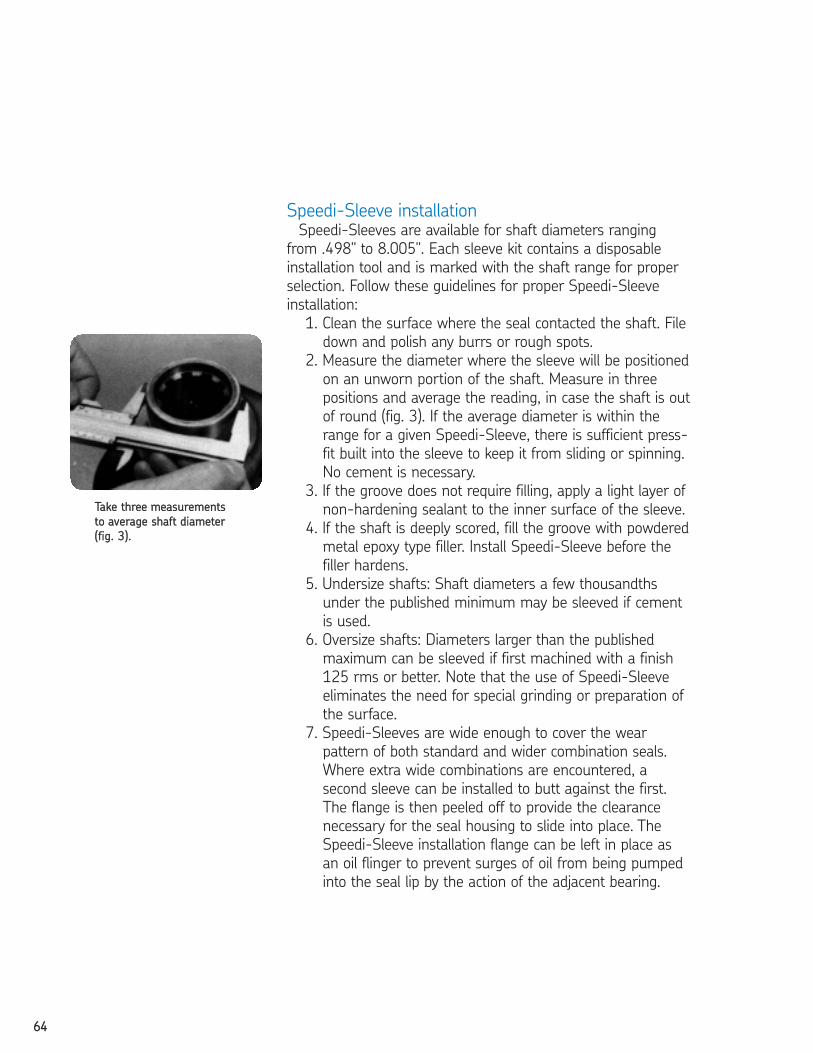
6644
Speedi-Sleeve installationSpeedi-Sleeves are available for shaft diameters ranging
from .498" to 8.005". Each sleeve kit contains a disposable
installation tool and is marked with the shaft range for proper
selection. Follow these guidelines for proper Speedi-Sleeve
installation:
1. Clean the surface where the seal contacted the shaft. File
down and polish any burrs or rough spots.
2. Measure the diameter where the sleeve will be positioned
on an unworn portion of the shaft. Measure in three
positions and average the reading, in case the shaft is out
of round (fig. 3). If the average diameter is within the
range for a given Speedi-Sleeve, there is sufficient press-
fit built into the sleeve to keep it from sliding or spinning.
No cement is necessary.
3. If the groove does not require filling, apply a light layer of
non-hardening sealant to the inner surface of the sleeve.
4. If the shaft is deeply scored, fill the groove with powdered
metal epoxy type filler. Install Speedi-Sleeve before the
filler hardens.
5. Undersize shafts: Shaft diameters a few thousandths
under the published minimum may be sleeved if cement
is used.
6. Oversize shafts: Diameters larger than the published
maximum can be sleeved if first machined with a finish
125 rms or better. Note that the use of Speedi-Sleeve
eliminates the need for special grinding or preparation of
the surface.
7. Speedi-Sleeves are wide enough to cover the wear
pattern of both standard and wider combination seals.
Where extra wide combinations are encountered, a
second sleeve can be installed to butt against the first.
The flange is then peeled off to provide the clearance
necessary for the seal housing to slide into place. The
Speedi-Sleeve installation flange can be left in place as
an oil flinger to prevent surges of oil from being pumped
into the seal lip by the action of the adjacent bearing.
TTaakkee tthhrreeee mmeeaassuurreemmeennttss
ttoo aavveerraaggee sshhaafftt ddiiaammeetteerr
((ffiigg.. 33))..
2604293 TFO Self Study Guide_V3 12/1/06 9:51 AM Page 64
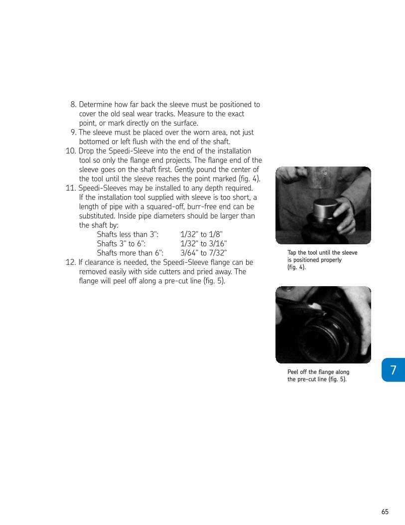
6655
8. Determine how far back the sleeve must be positioned to
cover the old seal wear tracks. Measure to the exact
point, or mark directly on the surface.
9. The sleeve must be placed over the worn area, not just
bottomed or left flush with the end of the shaft.
10. Drop the Speedi-Sleeve into the end of the installation
tool so only the flange end projects. The flange end of the
sleeve goes on the shaft first. Gently pound the center of
the tool until the sleeve reaches the point marked (fig. 4).
11. Speedi-Sleeves may be installed to any depth required.
If the installation tool supplied with sleeve is too short, a
length of pipe with a squared-off, burr-free end can be
substituted. Inside pipe diameters should be larger than
the shaft by:
Shafts less than 3": 1/32" to 1/8"
Shafts 3" to 6": 1/32" to 3/16"
Shafts more than 6": 3/64" to 7/32"
12. If clearance is needed, the Speedi-Sleeve flange can be
removed easily with side cutters and pried away. The
flange will peel off along a pre-cut line (fig. 5).
77
TTaapp tthhee ttooooll uunnttiill tthhee sslleeeevvee
iiss ppoossiittiioonneedd pprrooppeerrllyy
((ffiigg.. 44))..
PPeeeell ooffff tthhee ffllaannggee aalloonngg
tthhee pprree--ccuutt lliinnee ((ffiigg.. 55))..
2604293 TFO Self Study Guide_V3 12/1/06 9:51 AM Page 65
6666
To take this test, simply place a card or sheet of paper under the first question.
After you’ve read it (and answered it to yourself), slide the paper down below the
next question. The correct answer to the first problem will appear directly to the
right of the new question. Be sure not to skip any of the questions. This learning
technique assures more than four times the normal retention rate for even this
technical subject.
01. can cause a seal lip to groove the shaft.❏ a. Dust, heat and dirt❏ b. Lack of lubrication❏ c. A cocked seal❏ d. All of the above
1. D
02. The Speedi-Sleeve is an ultra-thin wear sleeve made of .❏ a. bronze❏ b. stainless steel❏ c. zinc❏ d. magnesium
2. B
03. Applying a wear sleeve over a damaged surface can .❏ a. eliminate shaft leaks❏ b. make the shaft usable again❏ c. smooth out damaged surfaces❏ d. all of the above
3. D
04. Speedi-Sleeves can be used on .❏ a. transmissions❏ b. pinions❏ c. front and rear crankshafts❏ d. all of the above
4. D
05. If the shaft is deeply scored, the groove should be .❏ a. filled with an epoxy type filler❏ b. filed down to a smooth surface❏ c. lubricated with oil❏ d. all of the above
5. A
CHAPTER 7 REVIEW
2604293 TFO Self Study Guide_V3 12/1/06 9:51 AM Page 66

6677
77
06. The inside diameter of a pipe used to install a 4" Speedi-Sleeve should be larger than the shaft.
❏ a. at least 1/2"❏ b. less than 1/2"❏ c. 1/32" – 3/16"❏ d. 3/4"
6. C07. When a seal groove on a shaft can be felt with a fingernail or paper
clip, it must be repaired.❏ True ❏ False
7. T08. Shaft wear can accelerate as operating conditions worsen.
❏ True ❏ False8. T
09. Continuous contact between a seal and rotating shaft will always cause shaft polishing friction.
❏ True ❏ False9. T
10. A deeply scored shaft can only be corrected by remetalizing the surface or replacing the shaft.
❏ True ❏ False10. F
11. Installing a Speedi-Sleeve is expensive and requires substantial downtime.❏ True ❏ False
11. F12. The first step to Speedi-Sleeve installation is removal of the shaft.
❏ True ❏ False12. F
13. The surface of the Speedi-Sleeve can actually outlast the original shaft surface.
❏ True ❏ False13. T
14. When installing a Speedi-Sleeve over a shaft, the original size seal can still be used.
❏ True ❏ False14. T
15. Each Speedi-Sleeve is built with a removable flange and includes a special tool for installation.
❏ True ❏ False15. T
2604293 TFO Self Study Guide_V3 12/1/06 9:51 AM Page 67

6688
CHAPTER 8 TROUBLESHOOTING SHAFT SEALS
AND SCOTSEALSYou now know the various types of seals available, can
select the right seal for the right application, and are able to
install it. But before you replace that next seal, there are some
troubleshooting points that will round out your knowledge
of seals.
SShhaafftt sseeaallss
Preliminary surveyThe best way to troubleshoot is to follow a sequence of steps
that should lead you to the problem.
1. What was the seal supposed to do? How well has it done
the job in the past? If there is a history of failures, the
problem may not be caused by the seal itself.
2. Was it the right seal? Check the seal’s part number and
look up its recommended applications. If the correct seal
has been installed and there is no history of repeated
failures, the problem requires further investigation.
3. Pinpoint the source of the leak. It may be either an I.D.
leak or an 0.D. leak. Also, find out when the leak first
occurred and see if this relates to a change in mainte-
nance or operating procedures (fig. 1).
IInnvveessttiiggaattee cclluueess
SSeeaall mmaarrkkiinnggssThe two areas that should be thoroughly checked are the seal
outer diameter (0.D.) and the seal inner diameter (I.D.). Tell-tale
marks on either of these areas can give you a good idea of why
the seal failed.
The solutionThe first surface to check is the 0.D. If the seal has been
properly installed, the press-fit markings will be fairly uniform
and straight.
CCoocckkeedd sseeaallMarkings also can be tell-tale signs that the seal was cocked
during installation.
Light scratches on the front of the seal would appear when
the seal was first inserted. Since the seal was cocked, it takes
additional force to seat the back half. This extra force causes
heavier markings on the back of the seal (fig. 2).
CChheecckk tthhee sseeaall aarreeaa ffoorr
lleeaakkss ((ffiigg.. 11))..
TThhiiss sseeaall wwaass ccoocckkeedd dduurriinngg
iinnssttaallllaattiioonn ((ffiigg.. 22))..
2604293 TFO Self Study Guide_V3 12/1/06 9:51 AM Page 68
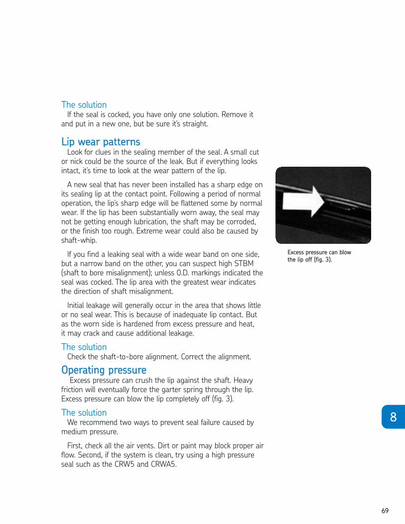
6699
88
The solutionIf the seal is cocked, you have only one solution. Remove it
and put in a new one, but be sure it’s straight.
LLiipp wweeaarr ppaatttteerrnnssLook for clues in the sealing member of the seal. A small cut
or nick could be the source of the leak. But if everything looks
intact, it’s time to look at the wear pattern of the lip.
A new seal that has never been installed has a sharp edge on
its sealing lip at the contact point. Following a period of normal
operation, the lip’s sharp edge will be flattened some by normal
wear. If the lip has been substantially worn away, the seal may
not be getting enough lubrication, the shaft may be corroded,
or the finish too rough. Extreme wear could also be caused by
shaft-whip.
If you find a leaking seal with a wide wear band on one side,
but a narrow band on the other, you can suspect high STBM
(shaft to bore misalignment); unless 0.D. markings indicated the
seal was cocked. The lip area with the greatest wear indicates
the direction of shaft misalignment.
Initial leakage will generally occur in the area that shows little
or no seal wear. This is because of inadequate lip contact. But
as the worn side is hardened from excess pressure and heat,
it may crack and cause additional leakage.
The solutionCheck the shaft-to-bore alignment. Correct the alignment.
OOppeerraattiinngg pprreessssuurreeExcess pressure can crush the lip against the shaft. Heavy
friction will eventually force the garter spring through the lip.
Excess pressure can blow the lip completely off (fig. 3).
The solutionWe recommend two ways to prevent seal failure caused by
medium pressure.
First, check all the air vents. Dirt or paint may block proper air
flow. Second, if the system is clean, try using a high pressure
seal such as the CRW5 and CRWA5.
EExxcceessss pprreessssuurree ccaann bbllooww
tthhee lliipp ooffff ((ffiigg.. 33))..
2604293 TFO Self Study Guide_V3 12/1/06 9:51 AM Page 69

7700
EExxcceessssiivvee tteemmppeerraattuurreeThe condition of the sealing element can also tell us about
temperature conditions. If the lip is hardened and brittle with
many cracks in its surface, overheating is probably the cause
(fig. 4).
A seal lip gradually hardens as it ages, but it should remain
flexible if temperatures do not exceed the recommended
maximums for the sealing material.
Sometimes heat is high enough to break down the oil,
but not hot enough to harden the lip. In this case, sludge
accumulates and is deposited on the seal lip.
The solutionWhen a sludge deposit cracks or breaks off, leakage paths are
created. A change in seal material or design will do little to
improve sealing performance. Instead, find a lubricant that is
more stable at high temperatures. Either that, or try to reduce
the operating temperature.
IInnccoorrrreecctt lluubbrriiccaannttA modern lubricant may employ many chemicals to improve
its performance. Unfortunately, additives that improve the lube
may adversely affect the seal.
Disulfide additives, for example, give lubricants anti-wear
properties, but they also cure or harden the sealing element.
Many EP (extreme pressure) lubes have additives that become
more active as they heat up. They also become more harmful
to the seal.
The solutionWhen the sealing member softens with use, or when there
is not sufficient overheating to explain the hardening you
observe, the problem could be that the lubricant and seal are
incompatible. The remedy is to go back to the SKF Handbook of
Seals (457010) and check seal material/fluid compatibility
specifications.
CCaassee ssttiillll uunnssoollvveedd??If none of the clues discussed so far are present, there still
are a few things that you can do:
• Check for foreign particles that may be temporarily trapped
under the lip.
• If it’s a spring-loaded seal, check to see if the garter spring
is still intact.
OOvveerrhheeaattiinngg ccaann ccaauussee
ccrraacckkss oonn tthhee sseeaall ssuurrffaaccee
((ffiigg.. 44))..
2604293 TFO Self Study Guide_V3 12/1/06 9:51 AM Page 70
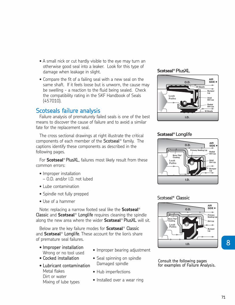
7711
88
• A small nick or cut hardly visible to the eye may turn an
otherwise good seal into a leaker. Look for this type of
damage when leakage in slight.
• Compare the fit of a failing seal with a new seal on the
same shaft. If it feels loose but is unworn, the cause may
be swelling - a reaction to the fluid being sealed. Check
the compatibility rating in the SKF Handbook of Seals
(457010).
SSccoottsseeaallss ffaaiilluurree aannaallyyssiissFailure analysis of prematurely failed seals is one of the best
means to discover the cause of failure and to avoid a similar
fate for the replacement seal.
The cross sectional drawings at right illustrate the critical
components of each member of the SSccoottsseeaall® family. The
captions identify these components as described in the
following pages.
For Scotseal® PPlluussXXLL, failures most likely result from these
common errors:
• Improper installation
– O.D. and/or I.D. not lubed
• Lube contamination
• Spindle not fully prepped
• Use of a hammer
Note: replacing a narrow footed seal like the Scotseal®
CCllaassssiicc and Scotseal® LLoonngglliiffee requires cleaning the spindle
along the new area where the wider Scotseal® PPlluussXXLL will sit.
Below are the key failure modes for Scotseal® CCllaassssiicc
and Scotseal® LLoonngglliiffee. These account for the lion’s share
of premature seal failures.
•• IImmpprrooppeerr iinnssttaallllaattiioonn
Wrong or no tool used
•• CCoocckkeedd iinnssttaallllaattiioonn
•• LLuubbrriiccaanntt ccoonnttaammiinnaattiioonn
Metal flakes
Dirt or water
Mixing of lube types
Scotseal® LLoonngglliiffee
SSccoottsseeaall® CCllaassssiicc
Scotseal® PPlluussXXLL
CCoonnssuulltt tthhee ffoolllloowwiinngg ppaaggeess ffoorr eexxaammpplleess ooff FFaaiilluurree AAnnaallyyssiiss..
• Improper bearing adjustment
• Seal spinning on spindle
Damaged spindle
• Hub imperfections
• Installed over a wear ring
2604293 TFO Self Study Guide_V3 12/1/06 9:51 AM Page 71

7722
Scotseal®® Classic // Scotseal®® LonglifeEExxtteerrnnaall iinnssppeeccttiioonn –– oouutteerr ddiiaammeetteerrNNoorrmmaall ssccuuffffiinngg:: The surface will show some scraped areas, that’s
normal. But signs of nicks, scratches metal particles, or any foreign
material are warning flags that something else is amiss. Make sure
the hub bore is smooth and free of burrs or nicks (fig. 1).
OO..DD.. rraaddiiaall ggrroooovveess:: If the Bore-Tite® film has been scored all the
way across the width of the seal, you should inspect the hub for
burrs or damage. Before installation, the hub should be inspected
and cleaned with emery cloth or a fine file (fig. 2).
If you see lines around the
seal, several things could have
happened. If the lines are etched
to the metal, the seal could have
spun as a result of being the
wrong application or, more likely,
it was installed crooked or cocked.
As you can see in this example, the grooves run from high on the
right to low on the left, indicating a cocked installation. Most likely,
the seal was not properly “bottomed-out” or a centering tool was
not used – common causes of premature seal failure (fig. 3).
SShhiinnyy lleeaaddiinngg eeddggee:: Occasionally someone will try to improve seal
installation by changing the shape of the seal. They'll round off the
leading edge of the outer cup on a grinder. This distorts the outer
diameter and can possibly cause the seal to disassemble (fig. 4).
OOuutteerr ccuupp ddaammaaggee:: If you see dents, nicks, or a bent casing you
can bet that the seal was installed without the proper tool or the
tool was damaged. Gashes indicate the use of a sharp object, like
a screwdriver or punch (fig. 5).
((ffiigg.. 11))
((ffiigg.. 22))
((ffiigg.. 33))
((ffiigg.. 44))
((ffiigg.. 55))
2604293 TFO Self Study Guide_V3 12/1/06 9:51 AM Page 72
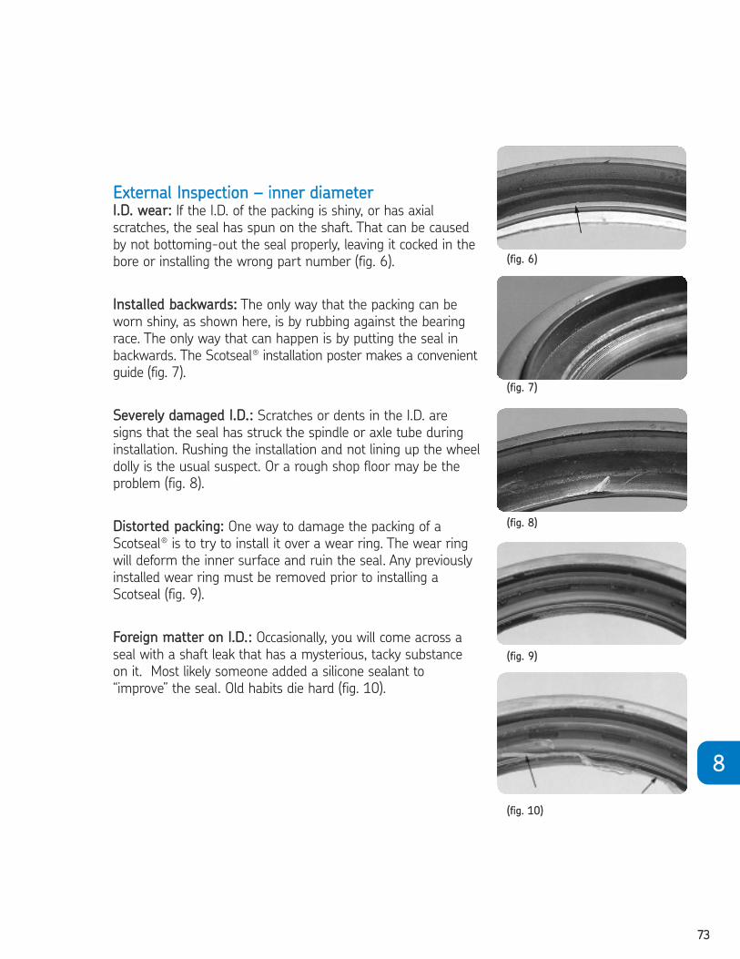
7733
88
EExxtteerrnnaall IInnssppeeccttiioonn –– iinnnneerr ddiiaammeetteerrII..DD.. wweeaarr:: If the I.D. of the packing is shiny, or has axial
scratches, the seal has spun on the shaft. That can be caused
by not bottoming-out the seal properly, leaving it cocked in the
bore or installing the wrong part number (fig. 6).
IInnssttaalllleedd bbaacckkwwaarrddss:: The only way that the packing can be
worn shiny, as shown here, is by rubbing against the bearing
race. The only way that can happen is by putting the seal in
backwards. The Scotseal® installation poster makes a convenient
guide (fig. 7).
SSeevveerreellyy ddaammaaggeedd II..DD..:: Scratches or dents in the I.D. are
signs that the seal has struck the spindle or axle tube during
installation. Rushing the installation and not lining up the wheel
dolly is the usual suspect. Or a rough shop floor may be the
problem (fig. 8).
DDiissttoorrtteedd ppaacckkiinngg:: One way to damage the packing of a
Scotseal® is to try to install it over a wear ring. The wear ring
will deform the inner surface and ruin the seal. Any previously
installed wear ring must be removed prior to installing a
Scotseal (fig. 9).
FFoorreeiiggnn mmaatttteerr oonn II..DD..:: Occasionally, you will come across a
seal with a shaft leak that has a mysterious, tacky substance
on it. Most likely someone added a silicone sealant to
“improve” the seal. Old habits die hard (fig. 10).
((ffiigg.. 66))
((ffiigg.. 77))
((ffiigg.. 88))
((ffiigg.. 99))
((ffiigg.. 1100))
2604293 TFO Self Study Guide_V3 12/1/06 9:51 AM Page 73
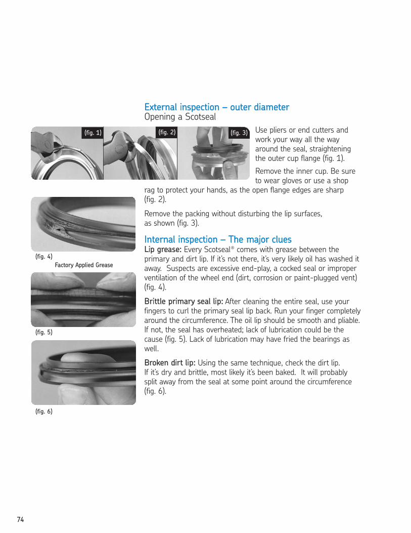
7744
FFaaccttoorryy AApppplliieedd GGrreeaassee
EExxtteerrnnaall iinnssppeeccttiioonn –– oouutteerr ddiiaammeetteerrOpening a Scotseal
Use pliers or end cutters and
work your way all the way
around the seal, straightening
the outer cup flange (fig. 1).
Remove the inner cup. Be sure
to wear gloves or use a shop
rag to protect your hands, as the open flange edges are sharp
(fig. 2).
Remove the packing without disturbing the lip surfaces,
as shown (fig. 3).
IInntteerrnnaall iinnssppeeccttiioonn –– TThhee mmaajjoorr cclluueessLLiipp ggrreeaassee:: Every Scotseal® comes with grease between the
primary and dirt lip. If it’s not there, it’s very likely oil has washed it
away. Suspects are excessive end-play, a cocked seal or improper
ventilation of the wheel end (dirt, corrosion or paint-plugged vent)
(fig. 4).
BBrriittttllee pprriimmaarryy sseeaall lliipp:: After cleaning the entire seal, use your
fingers to curl the primary seal lip back. Run your finger completely
around the circumference. The oil lip should be smooth and pliable.
If not, the seal has overheated; lack of lubrication could be the
cause (fig. 5). Lack of lubrication may have fried the bearings as
well.
BBrrookkeenn ddiirrtt lliipp:: Using the same technique, check the dirt lip.
If it’s dry and brittle, most likely it’s been baked. It will probably
split away from the seal at some point around the circumference
(fig. 6).
((ffiigg.. 11)) ((ffiigg.. 22))
((ffiigg.. 44))
((ffiigg.. 55))
((ffiigg.. 66))
((ffiigg.. 33))
2604293 TFO Self Study Guide_V3 12/1/06 9:51 AM Page 74
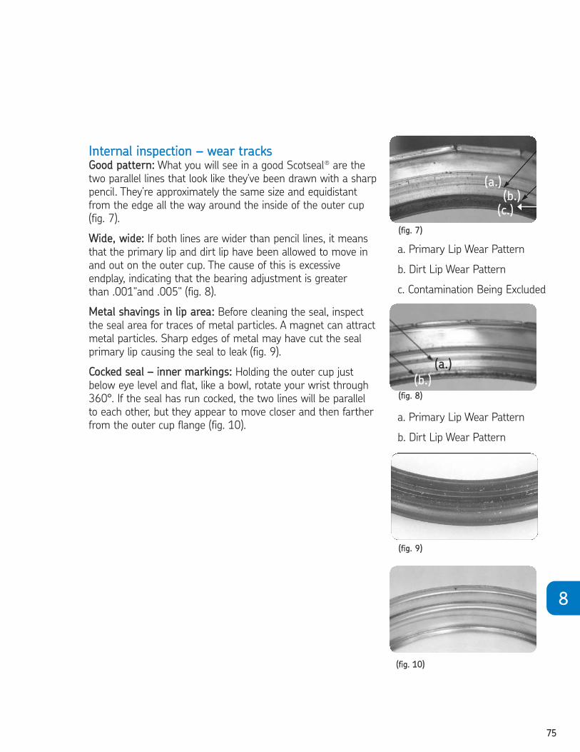
7755
88
IInntteerrnnaall iinnssppeeccttiioonn –– wweeaarr ttrraacckkssGGoooodd ppaatttteerrnn:: What you will see in a good Scotseal® are the
two parallel lines that look like they've been drawn with a sharp
pencil. They’re approximately the same size and equidistant
from the edge all the way around the inside of the outer cup
(fig. 7).
WWiiddee,, wwiiddee:: If both lines are wider than pencil lines, it means
that the primary lip and dirt lip have been allowed to move in
and out on the outer cup. The cause of this is excessive
endplay, indicating that the bearing adjustment is greater
than .001"and .005" (fig. 8).
MMeettaall sshhaavviinnggss iinn lliipp aarreeaa:: Before cleaning the seal, inspect
the seal area for traces of metal particles. A magnet can attract
metal particles. Sharp edges of metal may have cut the seal
primary lip causing the seal to leak (fig. 9).
CCoocckkeedd sseeaall –– iinnnneerr mmaarrkkiinnggss:: Holding the outer cup just
below eye level and flat, like a bowl, rotate your wrist through
360°. If the seal has run cocked, the two lines will be parallel
to each other, but they appear to move closer and then farther
from the outer cup flange (fig. 10).
((ffiigg.. 77))
((ffiigg.. 88))
((ffiigg.. 99))
((ffiigg.. 1100))
a. Primary Lip Wear Pattern
b. Dirt Lip Wear Pattern
c. Contamination Being Excluded
((aa..))
((bb..))
((aa..))
((bb..))
((cc..))
a. Primary Lip Wear Pattern
b. Dirt Lip Wear Pattern
2604293 TFO Self Study Guide_V3 12/1/06 9:51 AM Page 75

7766
Scotseal®® PlusXLEExxtteerrnnaall iinnssppeeccttiioonn –– cchheecckkiinngg tthhee bbeeaaddssNNoorrmmaall eexxtteerriioorr:: The tough HNBR material covering on the
Scotseal®PlusXL doesn’t supply clues as readily as Bore-Tite does.
But it can still reveal problems and lead to corrective measures.
There should be lubrication residue in each of the O.D., I.D. beads
(fig. 1).
DDrryy eexxtteerriioorr:: If, in good illumination, you cannot see any residual
lubrication between the beads of the outer sleeve, the seal may
have been installed dry. A Scotseal®PlusXL does not need special
tools, but it does need lubrication for proper installation (fig. 2).
DDaammaaggeedd OO..DD.. bbeeaaddss:: If the external ridges appear damaged,
most likely someone has tried to force the seal in place without
proper lubrication. Burrs or dirt in the bore can also cause
problems, but they’re not as visible with the thick HNBR rubber
protection (fig. 3).
WWoorrnn II..DD.. bbeeaaddss:: A worn I.D. indicates the seal has been slipping
on the spindle. Look for three main causes: a cocked seal, a bent
seal section, or poor spindle preparation in changing from another
seal to the Scotseal®PlusXL (fig. 4).
DDaammaaggeedd II..DD.. bbeeaaddss:: Cuts or scarring in the I.D. is caused by
jamming the seal into the spindle or axle tube. Misaligning the
wheel dolly is usually the result of haste, however the work area
should be checked to make sure the floor is smooth and free of
clutter (fig. 5).
DDeenntteedd,, ssccaarrrreedd sslleeeevvee aasssseemmbbllyy:: A dimpled or dented surface
indicates damage caused by a problem during installation. The use
of hard-faced tools or seal driver is the most likely culprit (fig. 6).
((ffiigg.. 11))
((ffiigg.. 22))
((ffiigg.. 33))
((ffiigg.. 44))
((ffiigg.. 55))
((ffiigg.. 66))
2604293 TFO Self Study Guide_V3 12/1/06 9:51 AM Page 76
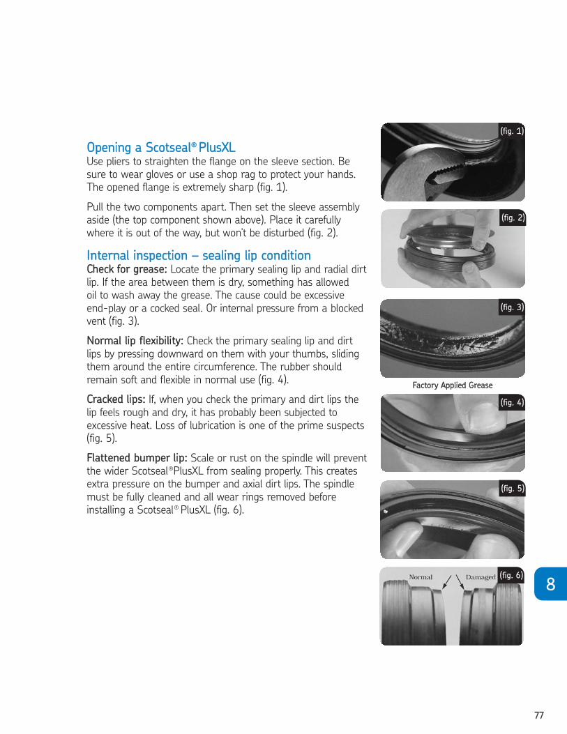
7777
88
OOppeenniinngg aa SSccoottsseeaall®® PPlluussXXLLUse pliers to straighten the flange on the sleeve section. Be
sure to wear gloves or use a shop rag to protect your hands.
The opened flange is extremely sharp (fig. 1).
Pull the two components apart. Then set the sleeve assembly
aside (the top component shown above). Place it carefully
where it is out of the way, but won’t be disturbed (fig. 2).
IInntteerrnnaall iinnssppeeccttiioonn –– sseeaalliinngg lliipp ccoonnddiittiioonnCChheecckk ffoorr ggrreeaassee:: Locate the primary sealing lip and radial dirt
lip. If the area between them is dry, something has allowed
oil to wash away the grease. The cause could be excessive
end-play or a cocked seal. Or internal pressure from a blocked
vent (fig. 3).
NNoorrmmaall lliipp fflleexxiibbiilliittyy:: Check the primary sealing lip and dirt
lips by pressing downward on them with your thumbs, sliding
them around the entire circumference. The rubber should
remain soft and flexible in normal use (fig. 4).
CCrraacckkeedd lliippss:: If, when you check the primary and dirt lips the
lip feels rough and dry, it has probably been subjected to
excessive heat. Loss of lubrication is one of the prime suspects
(fig. 5).
FFllaatttteenneedd bbuummppeerr lliipp:: Scale or rust on the spindle will prevent
the wider Scotseal®PlusXL from sealing properly. This creates
extra pressure on the bumper and axial dirt lips. The spindle
must be fully cleaned and all wear rings removed before
installing a Scotseal® PlusXL (fig. 6).
((ffiigg.. 11))
((ffiigg.. 22))
((ffiigg.. 33))
((ffiigg.. 44))
((ffiigg.. 55))
((ffiigg.. 66))
FFaaccttoorryy AApppplliieedd GGrreeaassee
2604293 TFO Self Study Guide_V3 12/1/06 9:51 AM Page 77

7788
a. Primary Lip Wear Pattern
b. Radial Dirt Lip Wear
Pattern
((aa..))
((bb..))
((aa..))
((bb..))
((aa..))
((bb..))
EExxtteerrnnaall iinnssppeeccttiioonn ––
pprriimmaarryy aanndd rraaddiiaall ddiirrtt lliipp wweeaarr ppaatttteerrnnssGGoooodd pprriimmaarryy lliipp ppaatttteerrnn:: You should see two parallel lines.
The primary lip line is slightly wider than the radial lip marking,
because it’s an SKF Waveseal® design (fig. 1).
WWiiddee,, wwiiddee:: If both of the tracks formed by the primary and dirt
lips are wide, chances are the whole wheel assembly is moving in
and out at an excessive rate. End-play like this causes leaks as well
as increased tire wear. The solution, of course, is proper bearing
adjustment (fig. 2).
WWiiddee,, tthhiinn:: If the primary seal lip line (bottom) is extra wide, while
the radial dirt lip line (top) is light, there is excessive pressure on
the primary lip. For steer and trailer axles that can be a plugged
vent, on drive axles the tube vent may be locked (fig. 3).
((ffiigg.. 11))
((ffiigg.. 22))
((ffiigg.. 33))
2604293 TFO Self Study Guide_V3 12/1/06 9:51 AM Page 78
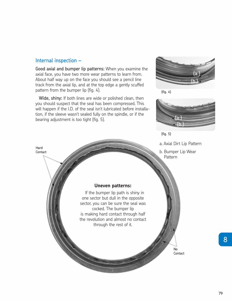
7799
88
Uneven patterns:
If the bumper lip path is shiny in
one sector but dull in the opposite
sector, you can be sure the seal was
cocked. The bumper lip
is making hard contact through half
the revolution and almost no contact
through the rest of it.
HHaarrdd
CCoonnttaacctt
NNoo
CCoonnttaacctt
IInntteerrnnaall iinnssppeeccttiioonn ––
GGoooodd aaxxiiaall aanndd bbuummppeerr lliipp ppaatttteerrnnss:: When you examine the
axial face, you have two more wear patterns to learn from.
About half way up on the face you should see a pencil line
track from the axial lip, and at the top edge a gently scuffed
pattern from the bumper lip (fig. 4).
WWiiddee,, sshhiinnyy:: If both lines are wide or polished clean, then
you should suspect that the seal has been compressed. This
will happen if the I.D. of the seal isn’t lubricated before installa-
tion, if the sleeve wasn’t sealed fully on the spindle, or if the
bearing adjustment is too tight (fig. 5).
((ffiigg.. 44))
((ffiigg.. 55))
a. Axial Dirt Lip Pattern
b. Bumper Lip Wear
Pattern
((aa..))
((bb..))
((aa..))
((bb..))
2604293 TFO Self Study Guide_V3 12/1/06 9:51 AM Page 79
8800
CHAPTER 8 REVIEWTo take this test, simply place a card or sheet of paper under the first question.
After you’ve read it (and answered it to yourself), slide the paper down below the
next question. The correct answer to the first problem will appear directly to the
right of the new question. Be sure not to skip any of the questions. This learning
technique assures more than four times the normal retention rate for even this
technical subject.
01. An alternating pattern of smooth and marked areas on the 0.D. indicates thatthe seal was probably .
❏ a. pressed into an out-of-round, over-size bore ❏ b. cocked during installation ❏ c. flattened by normal wear❏ d. misaligned
1. A
02. If a seal is cocked, it should be .❏ a. replaced❏ b. straightened❏ c. ignored❏ d. lubricated
2. A
03. Improper wear can cause a shaft to leak as a result of .❏ a. excessive STBM❏ b. excessive pressure❏ c. a cocked seal❏ d. all of the above
3. D
04. Pressure-caused seal failures may be corrected by .❏ a. opening air vents which may be plugged with dirt or paint❏ b. straightening the seal❏ c. reducing operating temperature❏ d. all of the above
4. A
05. If the seal lip is hardened and brittle with many cracks in its surface,is probably the cause.
❏ a. pressure❏ b. eccentricity❏ c. overheating❏ d. a cocked seal
5. C
2604293 TFO Self Study Guide_V3 12/1/06 9:51 AM Page 80
8811
06. Disulfide additives .❏ a. give lubricants anti-wear properties❏ b. can harden the sealing element❏ c. both of the above❏ d. neither of the above
6. C07. Many seal failures can be traced back to the condition of the
shaft or bore, or to poor installation.❏ True ❏ False
7. T08. The first surface to check for wear patterns or markings is the
inside diameter (I.D.) of the seal.❏ True ❏ False
8. F09. Improper installation can cause the seal to leak.
❏ True ❏ False9. T
10. If the lip of the seal wears away during normal operation, lesslubrication is required by the seal.
❏ True ❏ False10. F
11. If a leaking seal has a wide wear band on one side and a narrowband on the other, high STBM can be suspected.
❏ True ❏ False11. T
12. Heavy friction caused by excess pressure will eventually forcethe garter spring through the lip.
❏ True ❏ False12. T
13. If a sealing lip is hardened and brittle with cracks in the surface,the cause is probably excessive temperature.
❏ True ❏ False13. T
14. Chemicals that are used to improve a lubricant’s performancewill not spoil a seal.
❏ True ❏ False14. F
15. A small cut or nick on the sealing lip has no damaging effecton a good seal.
❏ True ❏ False15. F
88
2604293 TFO Self Study Guide_V3 12/1/06 9:51 AM Page 81

NOTES
2604293 TFO Self Study Guide_V3 12/1/06 9:51 AM Page 94

® SKF is a registered trademark of the SKF Group.
© SKF Group 2006. All rights reserved.
The contents of this publication are the copyright of the publisher and may not be
reproduced (even extracts) unless permission is granted. Every care has been taken to
ensure the accuracy of the information contained in this publication but no liability can
be accepted for any loss or damage whether direct, indirect or
consequential arising out of the use of the information contained herein.
SKF
890 North State Street, Suite 200 Elgin, Illinois 60123
1-800-882-0008 (U.S.) website: www.vsm.skf.com
1-866-832-6753 (Canada) website: www.skf.com
Printed in the U.S.A. Form No. 457935 (Rev. 11/06)
TFO_Cover06.CVR 12/1/06 9:43 AM Page 1