tft colorful display multiple-channel weather …
TRANSCRIPT

TFT COLORFUL DISPLAY
MULTIPLE-CHANNEL WEATHER STATION
DL5000
Operation Manual

OVERVIEW
1. Inventory of contents
QTY Item
1 Display Console
Frame Dimensions (LxHxW): 11.5 x 8.2 x 4cm
LCD Dimensions (LxW): 9.5 x 5.5cm
* Thermo-hygrometer transmitter (WH31)
Dimensions (LxHxW): 12 x 4 x 1.8cm
1 USB Cable for PC Connection
1 Adaptor
* 1,2,3,4, or 5, based on your order configuration.
Console
Figure 1 Figure 2
sensors

Figure 3
2. Introduction
Thank you for your purchase this professional weather station. This device can receive
signals up to at most 8 sensors. All the sensors measure temperature, humidity, heat index
and dew point and transmit to the console and displayed in defined channels.
This manual will guide you step-by-step through setting up your device. Use this manual to
become familiar with your professional weather station, and save it for future reference.
3. Getting Started
Note: The power up sequence is performed in the order shown in this section(insert
batteries in the display console first, remote transmitters second).
3.1 Display Console Set Up
Connect the console to AC power with the included AC adapter.
If the remotes do not update, please reference the troubleshooting guide in Section 0.
3.2 Thermo-Hygrometer Sensor Set Up
Note: To avoid operating problems, please take note of battery polarity before/when inserting
any Alkaline Batteries (permanent damaged could be introduced by inserting the battery in
wrong direction). Do not use rechargeable batteries. We recommend fresh alkaline batteries
for outdoor temperature range between -20℃and 60℃ and fresh lithium batteries for
outdoor temperature range between -40℃ and 60℃.
1. Move the transmitters(s) about 5 to 10’ away from the display console (if the transmitters
are too close, they may not be received by the display console). With multiple
transmitters, make sure all transmitters are powered up and displaying different
channels on the display.
2. Remove the battery door on the back of the thermo-hygrometer sensor by sliding down
the battery door, as shown in Figure 4.

Figure 4
3. BEFORE inserting the batteries, locate the dip switches on the inside cover of the lid
of the transmitter.
4. Channel Number: the weather station support up to eight sensors, and includes
three transmitters. To set each channel number, change Dip Switches 1,2,3 as
referenced in Figure 6.
5. Temperature unit of Measure: To change the sensor display units of measure (℉
or ℃), change Dip Switch 4, as referenced in Figure 5.
: Pull down the button : Pull up the button
Figure 5

6. Insert two AA batteries
7. Wait for seconds until temperature and humidity displayed on the LCD screen of
sensors.
8. Verify the correct channel number (CH) and temperature units of measure are on
the display, as shown in Figure 6.
Figure 6
(1) Temperature
(2) Temperature units ((℉ or ℃)
(3) Channel number
(4) Relative humidity
9. Close the battery door.
10. Repeat for the additional remote sensor, verifying each remote is on a different
channel.
3.3 Sensor Operation Verification
Verify the humidity sensors match closely with all of the sensors in the same location (about
5 to 10’ apart). The sensors should agree within 10% (the accuracy is ± 5%). Allow about
30 minutes for all sensors to stabilize. The humidity can be adjusted or calibrated later to
match each other a known source.
Verify the temperature sensors match closely with all of the sensors in the same location
(about 5 to 10’ apart). The sensors should be within 2°C (the accuracy is ± 1°C). Allow
about 30 minutes for all sensors to stabilize. The temperature can be adjusted or calibrated
later to match each other or a known source.
3.4 Radio Controlled Clock (RCC)
After the remote sensor is powered up, the sensor will transmit weather data for 30 seconds,
and then the sensor will begin radio controlled clock (RCC) reception. During the RCC time
reception period (maximum 5 minutes), no weather data will be transmitted to avoid

interference. Once the radio controlled time is received the RCC signal received successfully,
the RCC reception icon will turn on in the outdoor sensor LCD display. Then
outdoor sensor sends the RCC signal to display console, Once the radio controlled time is
received, RCC reception icon will turn on in the display console. (reference Figure 10).
If the signal reception is not successful within 3 minute, the signal search will be cancelled
and will automatically resume every six hours until the signal is successfully captured. The
regular RF link will resume once RCC reception routine is finished. In some locations, RCC
reception may take a couple of days to receive the signal.
4. Remote Sensor Installation
Before mount the units, ensuring that the receiver can still pick up the signal from
transmitters. It is recommended to mount the sensors on a north facing wall, in a shaded
area. Direct sunlight and radiant heat sources will result in inaccurate temperature readings.
Although the sensors are water resistant, it is best to mount in a well protected area, such as
under an eve.
1. Use a screw or nail to affix the remote sensor to the wall, as shown in Figure 7
2. Hang the remote sensor up on string, as shown in Figure 8.
Figure 7 Figure 8
5. Program modes
5.1 Normal display Mode

Figure 10
1. Graph for Temperature/Dew point/heat index/humidity of Indoor/outdoor sensors.
2. Date and time.
3. Outdoor Temperature/Dew point/heat index/humidity for channel 1 and other channels
defined to be displayed in CH1 area in turn.
4. Outdoor Temperature/Dew point/heat index/humidity for channel 2 and other channels
defined to be displayed in CH2 area in turn.
5. Outdoor Temperature/Dew point/heat index/humidity for channel 3 and other channels
defined to be displayed in CH3 area in turn.
6. Outdoor Temperature/Dew point/heat index/humidity for channel 4 and other channels
defined to be displayed in CH4 area in turn.
7. Outdoor Temperature/Dew point/heat index/humidity for channel 5 and other channels
defined to be displayed in CH5 area in turn.
8. Alarm icon
9. RCC reception icon
After the console receives data from each remote sensor, user can press these 4 buttons
for operation.
Figure 11

Icon Description
Graph key
Switch to display graph of Temperature/Dew point/heat
index/humidity for all sensors
Brightness control key
Press this key to increase the brightness
Brightness control key
Press this key to decrease the brightness
Menu Key
Press this key to enter menu and scroll to different modes
5.2 Setup Mode
Under Normal mode, press MENU key once to enter Setup Mode.
Icon Description
Scroll right key
Press this key to scroll down/right.
Selection key
Press this key to select and enter the option.
Scroll left key
Press this key to scroll up/left.
Mode key
Press this key to enter to next mode
Figure 12
CH Area1-5

Scroll to selected channel area, and press key to enter the setting interface as
below:
Icon Description
Scroll right key
Press this key to scroll down/up. .
Selection key
Press this key to select and enter the option.
Scroll left key
Press this key to scroll right/left.
Return key
Press this key to back to Setup main menu.
Figure 13
To modify the display parameter, press the up/down and left/right keys
to move the blue cursor to a sensor channel number (1-8) and parameter (temperature, dew
point, heat index).
Press key to display this channel and parameter in the selected area on the main
screen.
For example, if you wish to display Channel 1 Dew Point in the CH Area 1, highlight the
Channel 1 Dew point field.
If you wish to toggle both channel 1 temperature and channel 1 dew point, highlight both the
Channel 1 Temperature and Channel 1 Dew Point (reference Fehler! Verweisquelle konnte
nicht gefunden werden.),, and the screen will toggle between the channel 1 temperature and
dew point on the main screen once every 3 seconds.
If you wish to toggle both channel 2 temperature and channel 5 Dew point in the CH Area 2,
highlight both the Channel 2 Temperature and Channel 5 Dew point, and the screen will
toggle between the channel 5 temperature and dew point in the CH Area 2 once every 3
second.
Note: CH Area 1 can’t shift display other channel parameter and just display channel 1
sensor parameter.
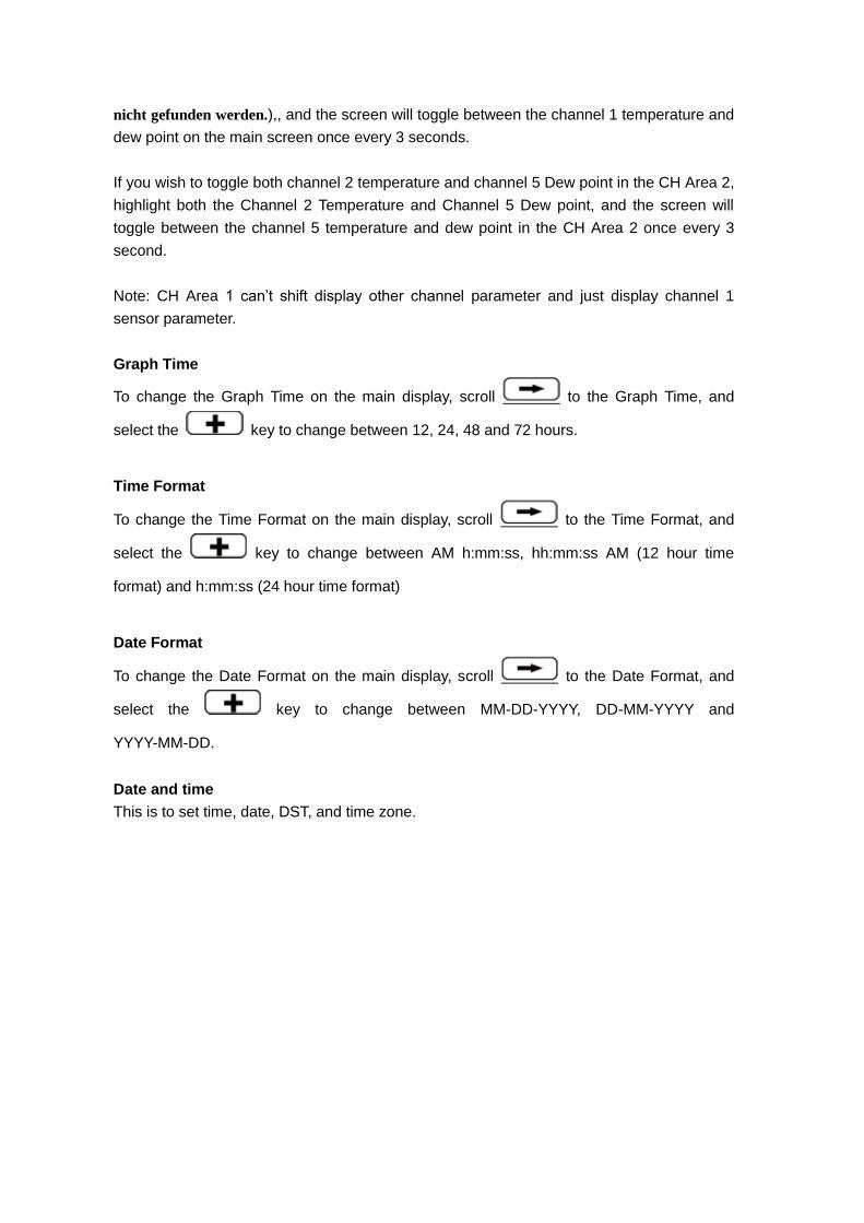
Graph Time
To change the Graph Time on the main display, scroll to the Graph Time, and
select the key to change between 12, 24, 48 and 72 hours.
Time Format
To change the Time Format on the main display, scroll to the Time Format, and
select the key to change between AM h:mm:ss, hh:mm:ss AM (12 hour time
format) and h:mm:ss (24 hour time format)
Date Format
To change the Date Format on the main display, scroll to the Date Format, and
select the key to change between MM-DD-YYYY, DD-MM-YYYY and
YYYY-MM-DD.
Date and time
This is to set time, date, DST, and time zone.
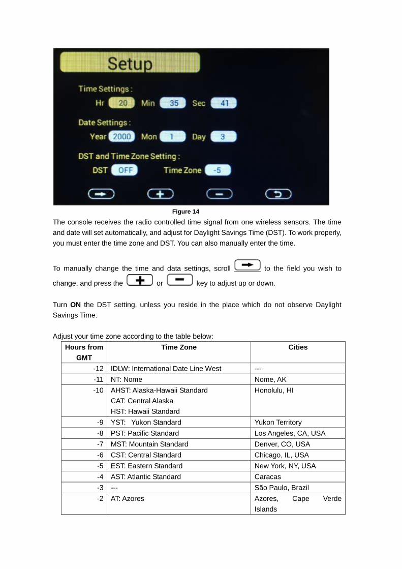
Figure 14
The console receives the radio controlled time signal from one wireless sensors. The time
and date will set automatically, and adjust for Daylight Savings Time (DST). To work properly,
you must enter the time zone and DST. You can also manually enter the time.
To manually change the time and data settings, scroll to the field you wish to
change, and press the or key to adjust up or down.
Turn ON the DST setting, unless you reside in the place which do not observe Daylight
Savings Time.
Adjust your time zone according to the table below:
Hours from
GMT
Time Zone Cities
-12 IDLW: International Date Line West ---
-11 NT: Nome Nome, AK
-10 AHST: Alaska-Hawaii Standard
CAT: Central Alaska
HST: Hawaii Standard
Honolulu, HI
-9 YST: Yukon Standard Yukon Territory
-8 PST: Pacific Standard Los Angeles, CA, USA
-7 MST: Mountain Standard Denver, CO, USA
-6 CST: Central Standard Chicago, IL, USA
-5 EST: Eastern Standard New York, NY, USA
-4 AST: Atlantic Standard Caracas
-3 --- São Paulo, Brazil
-2 AT: Azores Azores, Cape Verde
Islands

Hours from
GMT
Time Zone Cities
-1 WAT: West Africa ---
0 GMT: Greenwich Mean
WET: Western European
London, England
1 CET: Central European Paris, France
2 EET: Eastern European Athens, Greece
3 BT: Baghdad Moscow, Russia
4 --- Abu Dhabi, UAE
5 --- Tashkent
6 --- Astana
7 --- Bangkok
8 CCT: China Coast Bejing
9 JST: Japan Standard Tokyo
10 GST: Guam Standard Sydney
11 --- Magadan
12 IDLE: International Date Line East
NZST: New Zealand Standard
Wellington, New Zealand
Figure 15
Temperature Units
To change the temperature units of measure, scroll to the Temperature Units field,
and press the key to toggle between °F and °C.
5.3 Calibration Mode
Under Normal mode, press MENU key twice to enter Calibration Mode. Users can calibrate
the temperature and humidity of wireless sensors here.

Icon Description
Scroll down/right key
Press this key to scroll down/right. .
Selection/value increase key
Press this key to select parameter and enter the calibration
interface. Increase the value during calibration.
Value Decrease key
Decrease the value during calibration.
Scroll up/left key
Press this key to scroll up/left.
Mode key
Press this key to enter to next mode
Return Key
Back to main menu of calibration mode.
Resume Key
Cancel the calibration and resume.
Figure 16
Scroll to the temperature or humidity field you wish to calibrate, press the
key to perform the calibration, and press the or key to match your
calibration source.

Figure 17
5.3.1 Notes about Calibration
Note: The calibrated value can only be adjusted on the console. The remote sensor(s)
always displays the un-calibrated or measured value.
Note: The measured humidity range is between 10 and 99%. Humidity cannot be
accurately measured outside of this range. Thus, the humidity cannot be calibrated below
10% or above 99%.
The purpose of calibration is to fine tune or correct for any sensor error associated with the
devices margin of error. The measurement can be adjusted from the console to calibrate to a
known source.
Calibration is only useful if you have a known calibrated source you can compare it against,
and is optional. This section discusses practices, procedures and sources for sensor
calibration to reduce manufacturing and degradation errors. Do not compare your readings
obtained from sources such as the internet, radio, television or newspapers. They are in a
different location and typically update once per hour.
The purpose of your weather station is to measure conditions of your surroundings, which
vary significantly from location to location.
5.3.2 Humidity Calibration Methods
Official stations recalibrate or replace humidity sensors on a yearly basis. Due to
manufacturing tolerances, the humidity is accurate to ± 5%. To improve this accuracy, the
indoor and outdoor humidity can be calibrated using an accurate source, such as a sling
psychrometer or one step humidpak calibration kits.
5.3.3 Temperature Calibration Methods
Temperature errors can occur when a sensor is placed too close to a heat source (such as a
building structure, the ground or trees).
To calibrate temperature, we recommend a mercury or red spirit (fluid) thermometer.
Bi-metal (dial) and other digital thermometers are not a good source and have their own
margin of error. Using a local weather station in your area is also a poor source due to
changes in location, timing (airport weather stations are only updated once per hour) and
possible calibration errors (many official weather stations are not properly installed and
calibrated).
Place the sensor in a shaded, controlled environment next to the fluid thermometer, and
allow the sensor to stabilize for 48 hours. Compare this temperature to the fluid thermometer
and adjust the console to match the fluid thermometer.
5.4 Max/Min & Alarm Mode
Under Normal mode, press MENU key three times to enter Max/Min & Alarm Mode. Users
can check max/min records of temperature, humidity, dew point, heat index of each sensor.
And ice warning, high/low alarms of humidity and temperature can be configured here.

Icon Description
Scroll down/right key
Press this key to scroll down/right. .
Selection/value increase key
Press this key to select parameter to check according max/min
records. Switch on/off alarms and increase the value during alarm
setup.
Value Decrease key
Decrease the value during alarm setup.
Scroll up/left key
Press this key to scroll up/left.
Mode key
Press this key to enter to next mode
Return Key
Back to main menu of calibration mode.
Resume Key
Cancel the calibration and resume.
Figure 18
5.4.1 Max/Min
Scroll to the temperature, humidity, dew point or heat index min/max field you wish
to view, and press the key. Note that dashes (--.-) will be displayed for sensors that
are not programmed for your system.

Temperature Max/Min interface
Figure 19
To clear all of the min and max values, refer to Section Fehler! Verweisquelle konnte nicht
gefunden werden. for details.
Humidity Max/Min interface
Figure 20

Dew point Max/Min interface
Figure 21
Heat index Max/Min interface
Figure22

5.4.2 Alarm
You can set a high and low temperature and humidity alarm on Channels 1-8.
If the measured value is greater than the high alarm, an audible alert will sound and the
alarm icon will flash on the alarm panel, and the red color alarm icon will appear
on the main panel.
If the measured value is less than the high alarm, an audible alert will sound and the alarm
icon will flash on the alarm panel, and the grey color alarm icon will appear on
the main panel.
When an alarm has been triggered, the alarm will sound for 120 second and the corresponding alarm icon will flash until the alarm condition is no longer met. Press any key to silence the alarm. The alarm icon is color coded, and will flash as shown in Figure 23Fehler! Verweisquelle
konnte nicht gefunden werden. if one or more alarms are triggered.
Alarm Type
Color
High Alarm Red – grey - red
Low alarm Blue – grey - blue
High alarm & Low alarm both activated Red – grey – blue – grey – red
Beep alarm stop grey
Figure23
Scroll to the Humidity or Temperature Alarm On/Off switch, and press the
key to toggle the Humidity or Temperature Alarm On or Off.
Scroll to the Humidity Alarm or Temperature Alarm field, and press the
key to display the alarm programming panel, as shown in Fehler! Verweisquelle konnte nicht
gefunden werden..
Note: The alarm must be turned On to program the alarm settings.
Referring to Fehler! Verweisquelle konnte nicht gefunden werden., scroll to the
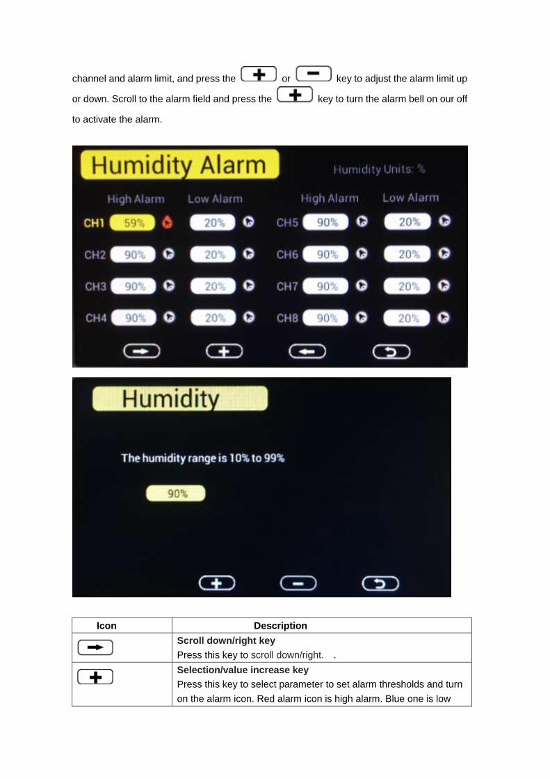
channel and alarm limit, and press the or key to adjust the alarm limit up
or down. Scroll to the alarm field and press the key to turn the alarm bell on our off
to activate the alarm.
Icon Description
Scroll down/right key
Press this key to scroll down/right. .
Selection/value increase key
Press this key to select parameter to set alarm thresholds and turn
on the alarm icon. Red alarm icon is high alarm. Blue one is low

alarm.
Value Decrease key
Decrease the value during alarm setup.
Scroll up/left key
Press this key to scroll up/left.
Mode key
Press this key to back to main menu or enter to next mode
Return Key
Back to main menu of alarm menu.
Figure24
5.5 Factory
Under Normal mode, press MENU key four times to enter factory mode.
Figure25
Factory reset:
To restore to factory default, scroll to the Factory Reset field and press
to clear all settings and restore to factory default.
Clear Max/Min:
To clear all of the max and min values, scroll to the Clear Max/Min field and press
to view the clear Max/Min panel. Scroll the sensor you wish to clear, and press
to clear the stored max and min values of this sensor..

Figure26
Re-register sensors:
If sensor communication is lost with a specific sensor, you can re-acquire.
Scroll to the re-register sensors field, and press to view the re-register
panel.
Scroll the sensor you wish to register, and press to re-acquire this sensor. Press
the button to highlight Yes and press to confirm.
If the indoor sensor display “-- --”, please scroll to it and enter to Re-register the indoor
sensor.
.
About:
Scroll to the About field, and press to view the hardware and firmware
version.

Figure27
English:
Scroll to the Language field, and press to change the language
(currently only English is only supported).
Backlight:
Scroll to the BackLight field, and press to adjust the backlight features.
To turn on and off the back lit display at certain times during the day, scroll to the
Backlight control field, and select the key to check the Backlight Conrol switch.
Scroll to adjust the backlight on and off time. Press the or
keys to adjust the hours and minutes up or down.
.

Figure28
6. Other Features
6.1 SD Card Export and Firmware Updates
With the use of an optional Micro SD Card, you can export data to a computer, save
historical graphs (in the event of a power failure) and update firmware when new versions
are released.
Figure 1
6.1.1 SD Data Export
The console includes a micro SD / TF card slot on the right side, as shown in Fehler!
Verweisquelle konnte nicht gefunden werden..
Backup data to micro SD / TF card (see the Accessories section of this manual for more
information on micro SD / TF cards).

The SD card will record data into the HISTORY directory.
The file is comma separated value (csv) and can be imported into Microsoft Excel, or other
text based applications.
The file format is as follows:
YYYYCH#A
where YYYY is the year, # is the channel number and A is the revision letter.
Example: 2016CH2A is the data for 2016, Channel 2, and A is the revision letter each time
you change a units of measure or calibration setting.
Below is an example of the file output:
Time,Temperature(F),Humidity(%),Dewpoint(F),HeatIndex(F)
2016/02/18 08:05,48.7,32,20.3,48.7
2016/02/18 08:10,49.1,33,21.2,49.1
2016/02/18 08:15,49.1,31,19.8,49.1
6.1.2 Back Up Graph Data
In the event of a power failure, the graph data on the main screen is lost, unless an optional
MicroSD Card is inserted into the SD Card Slot. The graph back up data file located on the
SD Card is labeled GRAPH.bin.
6.2 PC Software
Optional PC Software is available
The software features:
Live Data Display
Program Date and Time
Program Custom Display
Set Alarms
Calibrate Temperature and Humidity
Export and Graph Data from the SD Card
Sync Date and Time from the Computer
7. Specification
Transmission distance in open field : 100meter max. Frequency : 868MHz
Temperature measure range: : -40 to 60°C
Resolution : 0.1°C

Humidity measuring range : 10% to 99%
Humidity accuracy : +/-5% (only guaranteed between 20 to 90% under 0-45°C)
Alarm duration : 120 sec
Water proof level : IPX3
Measuring interval
Outdoor sensor channel 1 : 61s
Outdoor sensor channel 2 : 62s
Outdoor sensor channel 3 : 63s
Outdoor sensor channel 4 : 69s
Outdoor sensor channel 5 : 65s
Outdoor sensor channel 6 : 66s
Outdoor sensor channel 7 : 67s
Outdoor sensor channel 8 : 68s
Power consumption
Base station (display console) : AC Power(included)
Remote sensor : 2xAA Alkaline or Lithium batteries (not included)
Battery life: Minimum 12 months for base station with one sensor and excellent reception.
Intermittent reception and multiple sensors may reduce the battery life.
Minimum 12 months for thermometer-hygrometer sensor (use lithium batteries in cold
weather climates less than -20 °C)

EasyTemp PC software User Manual
1.0 General Information
This Weather Station is a high quality, easy to use weather monitoring system that reads,
displays and records the weather data from multiple external sensors. Each sensor
measures temperature, humidity, and dew point of spot.
After installing the “EasyTemp” program on this CD-ROM, your PC can display all indoor
data as well as the weather data from the Base Station received from the external sensors.
For operation, simply use the USB cable supplied and connect the Base Station to the PC.
From now on you can start to track current and history weather information at your finger
tips.
2.0 System Requirements
Operating System: Windows XP, Windows Vista. Windows 7, Windows 8, Windows 10
Base Station and PC must be connected by USB cable
3.0 Installation of the “EasyTemp” Software
Firstly, the Base Station and the Outdoor Sensors should be connected and checked for
correct function (see Operation Manual for TFT COLORFUL DISPLAY
MULTIPLE-CHANNEL WEATHER STATION for setting up the Weather Station). After
successful checking, install the “EasyTemp” software as follows:
1. Switch on your PC and insert the CD-ROM into the CD-ROM Drive.
2. Double click ““EasyTemp.exe””
3. Select the installation process language option and click ok
4. click next and select the destination folder(change directory when needed)
5. click next and select the shortcut folder(change directory when needed)
6. click next and select the additional tasks.
7. Click next and setup is now ready to begin installing EasyTemp on your computer.
8. Click install, software will be installed automatically
9. Press Finish to finish the installation process and exit. If you tick “Launch EasyTemp”
the software will start to run.
10. From “Start—All Programs—EasyTemp” path and double click the “EasyTemp” icon
to start application.
4.0 Basic Settings of the “EasyTemp” Software

4.1 Main Interface
After the “EasyTemp.exe” program has been started, the following main window will appear
on the PC screen:
The main display screen will display “Connected” if properly communicating through the USB
port.. The temperature, humidity and dew point measured by each external sensor will be
displayed on the main interface. And If no base station is connected, it shows ”USB
Unconnected”.
4.2 Function button:
Click Menu button, to enter function menu.

4.2.1 Time, Date and Display Setup
Select Menu | Setup to set the time, date and display customization settings.
From this screen you can set the graph type on the weather station screen (temperature,
humidity, dew point or heat index), graph hours, time zone and daylight savings settings,
time and date format, temperature units of measure, archive interval, and display
preferences (temperature, humidity, dew point or heat index).
For details, reference below:
All the settings from the base unit is mirrored into the PC software, so once you have done
your setting on the base unit, then you don’t need to make any setting changes on the PC
software. However you can still easily make any setting changes you wanted from the PC
and download the changes into the base station (the setting change will be refreshed when
next full minute arrives on the base station).
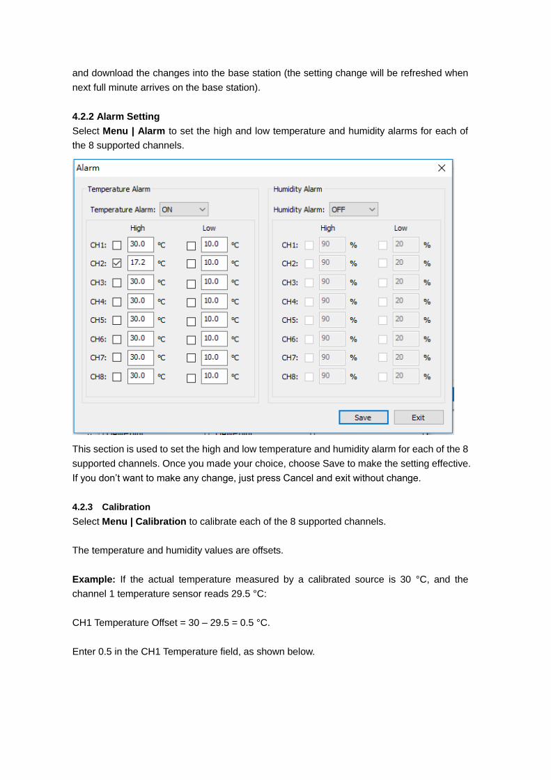
4.2.2 Alarm Setting
Select Menu | Alarm to set the high and low temperature and humidity alarms for each of
the 8 supported channels.
This section is used to set the high and low temperature and humidity alarm for each of the 8
supported channels. Once you made your choice, choose Save to make the setting effective.
If you don’t want to make any change, just press Cancel and exit without change.
4.2.3 Calibration
Select Menu | Calibration to calibrate each of the 8 supported channels.
The temperature and humidity values are offsets.
Example: If the actual temperature measured by a calibrated source is 30 °C, and the
channel 1 temperature sensor reads 29.5 °C:
CH1 Temperature Offset = 30 – 29.5 = 0.5 °C.
Enter 0.5 in the CH1 Temperature field, as shown below.

It may take a minute or two for the console to update the calibrated temperature, since the
temperature updates once per minute.
Note: There may be some °F to °C rounding error, since the native calculations are
performed in °C. For example, if you enter 0.6 °F in the field, 0.5 °F may be displayed the
next time you open this panel.
4.2.4 SDCard File
Note: The Micro SD Card is optional, not included and sold separately.
Select Menu | SDCard File to download and analyze data stored on the SD Card.
Select the file you wish to view from the list and press Select to view the data.
To graph the data:
1. Identify the data file start and end date and times.
2. Press the Graph button.
3. Enter the start and end date and times in the appropriate fields identified in Step 1.
4. Select the parameter you wish to graph, and press the Select button.

4.2.5. Sync time
Select Menu | Sync time to synchronize the time with PC time.

5. Best Practices for Wireless Communication
Note: To insure proper communication, mount the remote sensor on a vertical surface,
such as a wall. Do not lie the sensor flat.
Wireless communication is susceptible to interference, distance, walls and metal barriers.
We recommend the following best practices for trouble free wireless communication.
1. Electro-Magnetic Interference (EMI). Keep the console several feet away from
computer monitors and TVs.
2. Radio Frequency Interference (RFI). If you have other 433 MHz devices and
communication is intermittent, try turning off these other devices for troubleshooting
purposes. You may need to relocate the transmitters or receivers to avoid
intermittent communication.
3. Line of Sight Rating. This device is rated at 300 feet line of sight (no interference,
barriers or walls) but typically you will get 100 feet maximum under most real-world
installations, which include passing through barriers or walls.
4. Metal Barriers. Radio frequency will not pass through metal barriers such as
aluminum siding. If you have metal siding, align the remote and console through a
window to get a clear line of sight.
The following is a table of reception loss vs. the transmission medium. Each “wall” or
obstruction decreases the transmission range by the factor shown below.
Medium RF Signal Strength Reduction
Glass (untreated) 5-15%
Plastics 10-15%
Wood 10-40%
Brick 10-40%
Concrete 40-80%
Metal 90-100%

6. Glossary of Terms
Term Definition
Accuracy Accuracy is defined as the ability of a measurement to match the
actual value of the quantity being measured.
Hygrometer A hygrometer is a device that measures relative humidity.
Relative humidity is a term used to describe the amount or
percentage of water vapor that exists in air.
Range Range is defined as the amount or extent a value can be
measured.
7.Troubleshooting Guide
Problem Solution
Wireless remote (thermo-hygrometer)
not reporting in to console.
There are dashes (--.-) on the display
console, and these sensors are a port
of your system.
If any of the sensor communication is lost, dashes
(--.-) will be displayed on the screen. To reacquire
the signal, re-acquire the signal per Section Fehler!
Verweisquelle konnte nicht gefunden werden..
Please verify each sensor is on a different channel
by viewing the sensor’s LCD display.
The maximum line of sight communication range is
300’ and 100’ under most conditions. Move the
sensor assembly closer to the display console.
If the sensor assembly is too close (less than 5’),
move the sensor assembly away from the display
console.
Make sure the remote sensor LCD display is
working.
Install a fresh set of batteries in the remote
thermo-hygrometer. For cold weather
environments, install lithium batteries.
Make sure the remote sensors are not transmitting
through solid metal (acts as an RF shield), or earth
barrier (down a hill).
Move the display console around electrical noise
generating devices, such as computers, TVs and

Problem Solution
other wireless transmitters or receivers.
Move the remote sensor to a higher location. Move
the remote sensor to a closer location.
Temperature sensor reads too high in
the day time.
Make sure the thermo-hygrometer is mounted in a
shaded area on the north facing wall.
Temperature sensors do not agree Allow up to one hour for the sensors to stabilize due
to signal filtering. The sensors should agree within
2 °C (the sensor accuracy is ± 1 °C) under worst
case conditions.
Use the calibration feature to match the indoor and
outdoor temperature to a known source.
Humidity sensors do not agree Allow up to one hour for the sensors to stabilize due
to signal filtering. The indoor and outdoor humidity
sensors should agree within 10 % (the sensor
accuracy is ± 5 %) under worst case conditions.
Use the calibration feature to match the indoor and
outdoor humidity to a known source.
Display console contrast is weak Check the backlight display settings referenced in
Section Fehler! Verweisquelle konnte nicht gefunden
werden..