tft-lcd production process · pdf filetft-lcd production process explained ... lg display...
TRANSCRIPT
TFT-LCD Production Process Explained
Ever wondered how the TV and monitor displays you use every day work? The TFT-LCD
manufacturing process consists of a set of processes for producing TFT, color filtering, cell,
module and others. LG Display Newsroom gives a detailed, but easy to follow explanation of
the entire steps below.
Close Look at the Thin Film Translator (TFT) Process
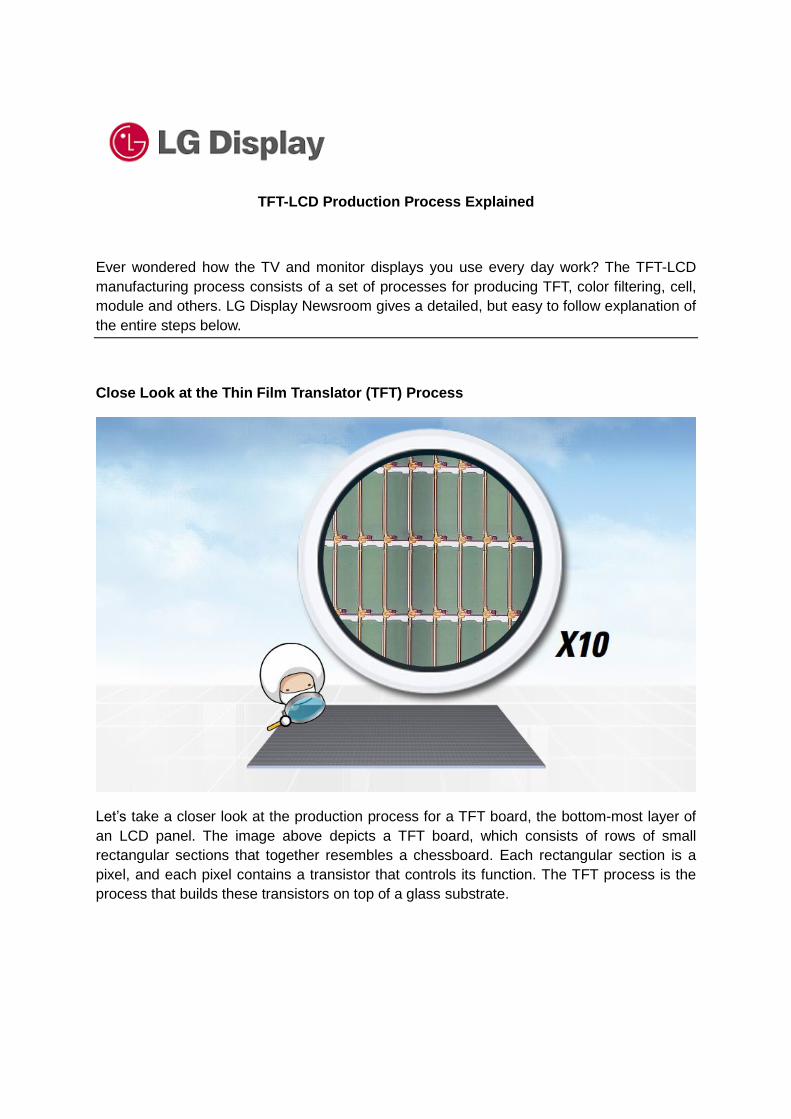
Let’s take a closer look at the production process for a TFT board, the bottom-most layer of
an LCD panel. The image above depicts a TFT board, which consists of rows of small
rectangular sections that together resembles a chessboard. Each rectangular section is a
pixel, and each pixel contains a transistor that controls its function. The TFT process is the
process that builds these transistors on top of a glass substrate.

So, what exactly is a transistor? Simply described, a transistor is a microscopic switch that
controls the flow of electricity in the direction of liquid crystal and regulates the movement of
the liquid crystal.
On top of a TFT board are millions of tiny transistors that are invisible to the naked eye, each
of which are one hundredth of the thickness of a single strand of hair. If you examine the

transistor up close, you would notice that it consists of several layers. Now, let’s see how
each layer is produced, starting with the first layer.
After cleaning the glass substrate (Cleaning), it is coated with a layer of film, which is
essential in creating the appropriate shape (Deposition). Then, a layer of light-sensitive
material is spread out on top of this film (Photo-resist coating). Through these steps, we can
create two layers, on which we can build parts of a transistor of various shapes and sizes as
you can see in the picture above.
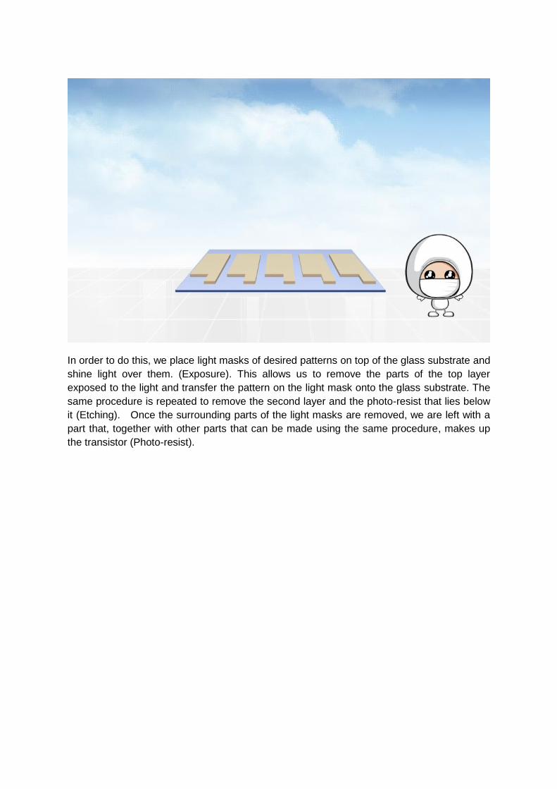
In order to do this, we place light masks of desired patterns on top of the glass substrate and
shine light over them. (Exposure). This allows us to remove the parts of the top layer
exposed to the light and transfer the pattern on the light mask onto the glass substrate. The
same procedure is repeated to remove the second layer and the photo-resist that lies below
it (Etching). Once the surrounding parts of the light masks are removed, we are left with a
part that, together with other parts that can be made using the same procedure, makes up
the transistor (Photo-resist).

In the past, the entire sequence had to be repeated eight times. However, technology has
developed such that we can make 2 to 3 layers at once, allowing us to build a transistor by
repeating the sequence only 4 times.
Close Look at the Color Filter (CF) Process
The next step to producing an LCD panel is the color filter process.
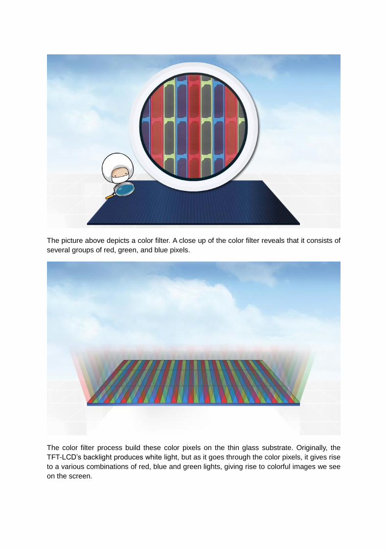
The picture above depicts a color filter. A close up of the color filter reveals that it consists of
several groups of red, green, and blue pixels.
The color filter process build these color pixels on the thin glass substrate. Originally, the
TFT-LCD’s backlight produces white light, but as it goes through the color pixels, it gives rise
to a various combinations of red, blue and green lights, giving rise to colorful images we see
on the screen.
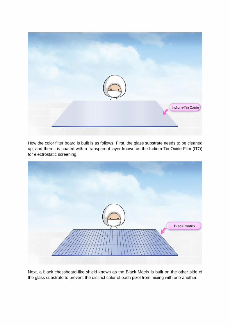
How the color filter board is built is as follows. First, the glass substrate needs to be cleaned
up, and then it is coated with a transparent layer known as the Indium-Tin Oxide Film (ITO)
for electrostatic screening.
Next, a black chessboard-like shield known as the Black Matrix is built on the other side of
the glass substrate to prevent the distinct color of each pixel from mixing with one another.

The next step is to create red, green, and blue pixels. First, a light-sensitive red material
(Red Photo-Resist) is spread out onto the glass substrate. Next, after shooting light onto the
mold (Mask), we must remove the exposed area in order to create our desired shape.
Lastly, we harden the red material by heating it in an oven. Through repeating this process,
we are able to create green and blue pixels.
The result of this process, however, is pixels of different heights. Another laminating layer
needs to be applied in order to even out the surface of the pixels. We then attach a small
supporting column. Finally, when we attach the TFT board in the next process, the use of

small supporting columns helps maintain a uniform distance between the color filter and the
TFT board.
Closer Look at the Cell Process
The following step is the cell process, the step in which the TFT board is combined with the
color filter and is cut into appropriate sizes. There are three steps to the cell process.

The first step is known as the alignment process, which aims to align the liquid crystal in a
uniform direction. How this can be achieved is easier than it sounds.
After thorough cleaning of the TFT board and the color filter, polyimide layer is printed onto
the TFT substrate and is hardened in the oven. Next, using a revolving roller intertwined with
a soft cloth, we create a series of shallow grooves that allows the liquid crystals to orient in a
uniform direction.

The next step is the combination process in which the TFT board and the color filter are
sealed together in a vacuum. First, a specific amount of liquid crystals are dispensed on top
of TFT board and an adhesive is applied to the color filter so it attaches to the TFT board.
Next, the glass substrates are sealed in a vacuum. During this phase, the liquid crystals
spread evenly between the two glass substrates.
The third step involves making a panel by cutting the glass substrates in to the desired

dimension. First, both sides of the glass substrates need to be cut simultaneously into their
appropriate sizes. Then, a grinder is used to smooth the edges. The panel is then cleaned to
remove any leftover dusts or debris.
Finally, an electrical signal is given to the finished panel to verify that all colors and shapes
are accurately displayed on the screen.
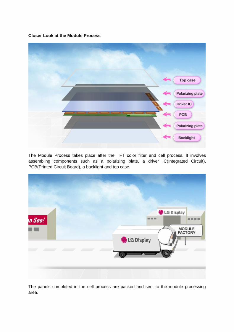
Closer Look at the Module Process
The Module Process takes place after the TFT color filter and cell process. It involves
assembling components such as a polarizing plate, a driver IC(Integrated Circuit),
PCB(Printed Circuit Board), a backlight and top case.
The panels completed in the cell process are packed and sent to the module processing
area.

The panels entering the module process are first cleaned with clean water and paper made
of organic materials to wash off debris produced during the cell process. The surfaces of the
panels are then wiped with a soft brush and air-dried for the next process.

Attaching the Polarizing Plate
This process involves attaching polarizing plates to both sides of the panels cleaned in the
previous step. A polarizing plate is a thin layer that allows the light through-either a horizontal
or vertical plane. Removal of the protective film on the polarizing plate exposes an adhesive
part that can be attached to one side of the panel using a roller.
One plate attached to one side of the panel is horizontally oriented while the plate attached
to the other side is vertically oriented, so that the light shined on one side cannot pass
through the plate on the other side. Then a question arises: if the light cannot pass through
the panel, how are the images on the screen produced? To maintain the perpendicular
pattern of the polarized plate’s other side, the reflected light is made unable to pass through
to the opposite side. The light cannot pass through, so how are we able to see videos
through the panel?

The liquid crystals in the TFT board play an essential role. First, the light from the backlight
passes through the polarizing plate and reaches the TFT board. The direction of the light is
changed here according to the alignment of the liquid crystals that orients themselves in
reaction to the strength of the electrical signals they receive. The colorful images we see on
TVs and monitors are created when the light passes through the red, green and blue pixels
and the other layer of the polarized plate in various directions.
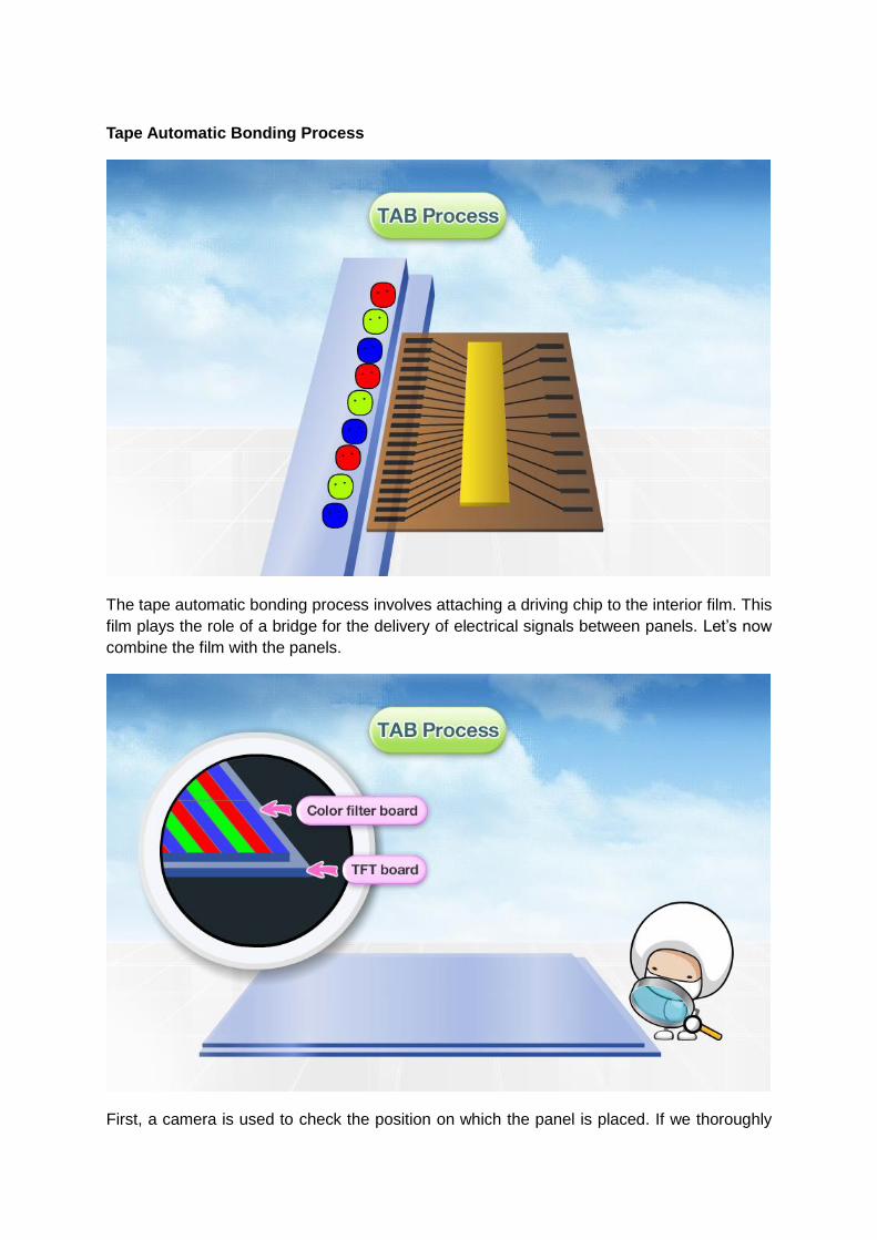
Tape Automatic Bonding Process
The tape automatic bonding process involves attaching a driving chip to the interior film. This
film plays the role of a bridge for the delivery of electrical signals between panels. Let’s now
combine the film with the panels.
First, a camera is used to check the position on which the panel is placed. If we thoroughly

check the panels, we see that the TFT board is larger than the color filter. On the left over
space around the edges of the TFT board, we apply an adhesive tape. Within the adhesive
tape lies a conductor which allows electrical signals to run through the driving chip and the
panel.
Like in the above projection, we cut out a long strand of film into a specific length and locate
each piece when high temperature and pressure are applied; the panels are finally securely
attached together.

Printed Circuit Board Process
Now, let’s see how the PCB (Printed Circuit Board) works. The PCB allows the driving chip
to transfer external signals to the built-in film. The PCB plays the role of receiving external
signals and transferring them to the driver chip inside the interior film.
To equivocate this to the tab process, as in the TAB process, we first apply an adhesive tape
(ACF: Anistropic Conductive Panel) on the surface of the PCB. Making sure that the films
are placed in their appropriate positions on the PCB, we apply high heat and pressure to
make sure the ACF adheres to the PCB.
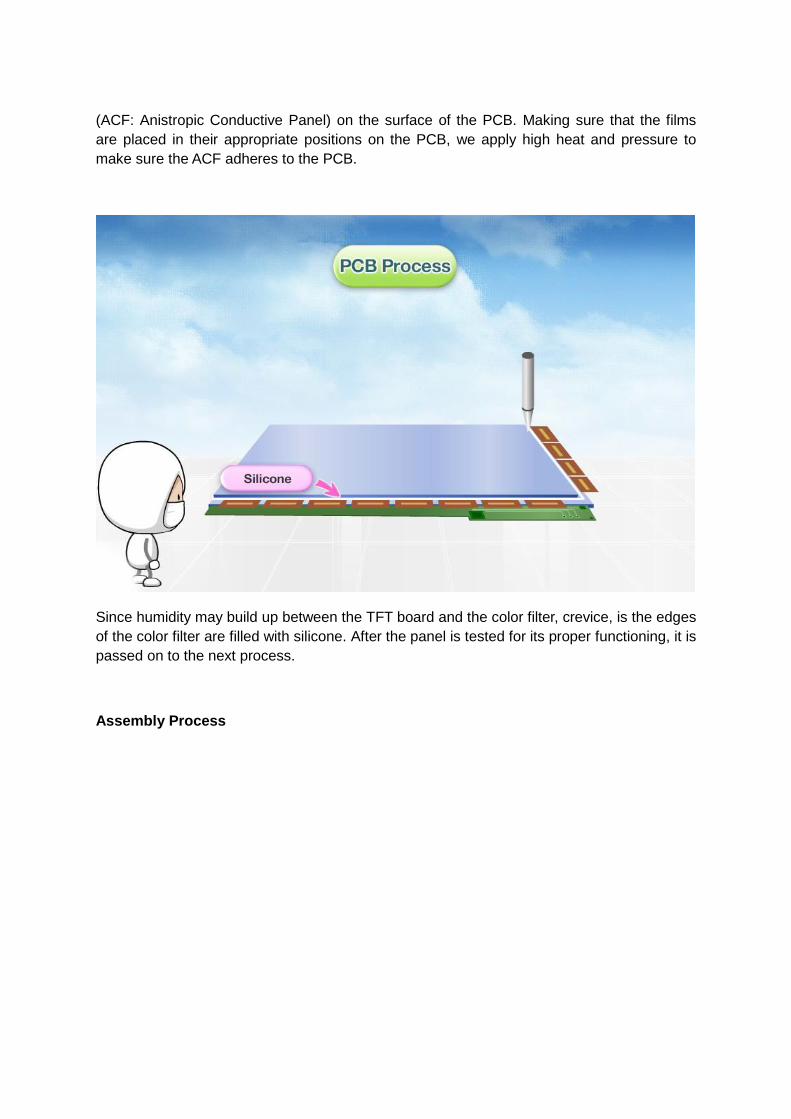
Since humidity may build up between the TFT board and the color filter, crevice, is the edges
of the color filter are filled with silicone. After the panel is tested for its proper functioning, it is
passed on to the next process.
Assembly Process

Because TFT-LCD panels cannot give off light on their own, they need a backlight installed
to do this for them. Let’s look into the constituents of the backlight.
The backlight consists of a sheet of reflector, which reflects light in the direction of the light
guide plate; the lamp assembly where the light originates; the diffuser that literally distributes
the light evenly on the surface of the reflector; another diffuser; and the guide panel that

fixes the sheets together and protects them from external shocks.
The panel that has gone through the PCB process is called the board assembly. We mount
this board assembly on the backlight and fold the PCB back. A top case is placed to fix the
panel and the backlight in place and to protect them from external shock. After attaching the
film to protect the screen of the panel and assemble a protective case for the PCB, we finally
have a TFT-LCD module.
Aging Process and the Final Checkup

The TFT-LCD module still needs to go through a series of verification process for quality
assurance, starting with aging process and the final-checkup. First, the screen needs to be
checked for its proper performance. Then enters the aging process in which it receives
electronic signals for a set amount of time under high temperature condition. This process
allows the liquid crystal to stabilize and enhances the reliability of the product. Lastly, after
several checkups, the product is finally guaranteed of its quality.

After the final checkup of the module, we run a visual checkup to make sure that the lines to
the backlight are well connected and the top case is assembled properly. After we run
another final checkup to ensure the perfect quality, the final product is wrapped in a
electrostatic protective material and boxed to be delivered to customers all around the world.