tg-263: standardizing nomenclatures in radiation oncology · aapm report no. 263 standardizing...
TRANSCRIPT
AAPM REPORT NO. 263
Standardizing Nomenclaturesin Radiation Oncology
The Report of AAPMTask Group 263
January 2018
DISCLAIMER: This publication is based on sourcesand information believed to be reliable, but theAAPM, the authors, and the editors disclaim any war-ranty or liability based on or relating to the contents ofthis publication.
The AAPM does not endorse any products, manufac-turers, or suppliers. Nothing in this publication shouldbe interpreted as implying such endorsement.
© 2018 by American Association of Physicists in Medicine

This page intentionally left blank.
Standardizing Nomenclaturesin Radiation Oncology
The Report of AAPM Task Group 263
Charles S. Mayo, ChairUniversity of Michigan, Ann Arbor, Michigan
Jean M. Moran, Vice ChairUniversity of Michigan, Ann Arbor, Michigan
Walter BoschWashington University, St. Louis, Missouri
Ying XiaoUniversity of Pennsylvania, Philadelphia, Pennsylvania
Todd McNuttJohns Hopkins University, Baltimore, Maryland
Richard PoppleUniversity of Alabama at Birmingham, Birmingham, Alabama
Jeff MichalskiWashington University, St. Louis, Missouri
Mary FengUniversity of California San Francisco, San Francisco, California
Lawrence B. MarksUniversity of North Carolina, Chapel Hill, North Carolina
Clifton D. FullerMD Anderson Cancer Center, Houston, Texas
Ellen YorkeMemorial Sloan Kettering Cancer Center, New York, New York
Jatinder PaltaVirginia Commonwealth University, Richmond, Virginia
Peter E. GabrielUniversity of Pennsylvania, Philadelphia, Pennsylvania
Andrea MolineuMD Anderson Cancer Center, Houston, Texas
Martha M. MatuszakUniversity of Michigan, Ann Arbor, Michigan
Elizabeth CovingtonBirmingham, Alabama
Kathryn MasiKarmanos Cancer Center, Detroit, Michigan
Susan L. RichardsonSwedish Medical Center, Seattle, Washington
Timothy RitterHunter Holmes McGuire VA Medical Center, Richmond, Virginia
Tomasz MorgasVarian Medical Systems, Palo Alto, California
Stella FlampouriUniversity of Florida, Jacksonville, Florida
Lakshmi SantanamWashington University, St. Louis, Missouri
Joseph A. MooreJohns Hopkins University, Baltimore, Maryland
Thomas G. PurdieThe Princess Margaret Cancer Center, Toronto, ON, Canada
Robert MillerMayo Clinic, Jacksonville, Florida
Coen HurkmansCatharina Hospital, Department of Radiation Oncology, Eindhoven, The Netherlands
Judy AdamsMassachusetts General Hospital, Boston, Massachusetts
Qing-Rong Jackie WuDuke University, Durham, North Carolina
Colleen J. FoxDartmouth-Hitchcock Medical Center, Lebanon, New Hampshire
Ramon Alfredo SiochiWest Virginia University, Morgantown, West Virginia
Norman L. BrownBaptist Medical Center, Jacksonville, Florida
Wilko VerbakelVU University Medical Center, Amsterdam, Netherlands
Yves ArchambaultVarian Medical Systems, Palo Alto, California
Steven J. ChmuraUniversity of Chicago, Chicago, Illinois
Don G. EagleNorthwest Medical Physics Center, Lynnwood, Washington
Thomas J. FitzgeraldUniversity of Massachusetts, Worcester, Massachusetts
Andre L. DekkerDepartment of Radiation Oncology (MAASTRO), GROW School for Oncology and Developmental Biology, Maastricht University Medical Centre+, Maastricht, The Netherlands
Theodore HongMassachusetts General Hospital, Boston, Massachusetts
Rishabh KapoorVirginia Commonwealth University, Richmond, Virginia
Beth LansingElekta Corporation, St. Louis, Missouri
Shruti JollyUniversity of Michigan, Ann Arbor, Michigan
Mary E. NapolitanoConsultant, Suwanee, Georgia
James PercyElekta Corporation, St. Louis, Missouri
Mark S. RoseSun Nuclear, Melbourne, Florida
Salim SiddiquiHenry Ford Health System, Detroit, Michigan
Christof SchadtBrain Lab, Chicago, Illinois
William E. SimonSun Nuclear Corporation, Melbourne, Florida
William L. StraubeWashington University, St. Louis, Missouri
Sara T. St. JamesUniversity of Washington, Seattle, Washington
Kenneth UlinUniversity of Massachusetts, Worcester, Massachusetts
Sue S. YomUniversity of California San Francisco, San Francisco, California
Torunn YockMassachusetts General Hospital, Boston, Massachusetts
DISCLAIMER: This publication is based on sources and information believed to be reliable,but the AAPM, the authors, and the publisher disclaim any warranty or liability
based on or relating to the contents of this publication.
The AAPM does not endorse any products, manufacturers, or suppliers. Nothing in thispublication should be interpreted as implying such endorsement.
ISBN: 978-1-936366-61-3ISSN: 0271-7344
© 2018 by American Association of Physicists in Medicine
All rights reserved
Published by
American Association of Physicists in Medicine1631 Prince Street
Alexandria, VA 22314
THE REPORT OF AAPM TASK GROUP 263:Standardizing Nomenclatures in Radiation Oncology
Contents
1. Introduction . . . . . . . . . . . . . . . . . . . . . . . . . . . . . . . . . . . . . . . . . . . . . . . . . . . . . . . 62. Background . . . . . . . . . . . . . . . . . . . . . . . . . . . . . . . . . . . . . . . . . . . . . . . . . . . . . . . 6
2.1 Data Pooling . . . . . . . . . . . . . . . . . . . . . . . . . . . . . . . . . . . . . . . . . . . . . . . . . . . . . . . . . . . . . . . . . . . . . . . . 62.2 Facilitating Communication During Routine Care . . . . . . . . . . . . . . . . . . . . . . . . . . . . . . . . . . . . . . . . . . 72.3 Automatic Data Extraction and Exchange. . . . . . . . . . . . . . . . . . . . . . . . . . . . . . . . . . . . . . . . . . . . . . . . . 72.4 Challenges Despite Some Progress . . . . . . . . . . . . . . . . . . . . . . . . . . . . . . . . . . . . . . . . . . . . . . . . . . . . . . 7
3. Task Group Initiation and Membership . . . . . . . . . . . . . . . . . . . . . . . . . . . . . . . . . 84. Initial Evaluation of Current Nomenclature Practices . . . . . . . . . . . . . . . . . . . . 9
4.1 Dose and Volume Units . . . . . . . . . . . . . . . . . . . . . . . . . . . . . . . . . . . . . . . . . . . . . . . . . . . . . . . . . . . . . . . 94.2 Non-Target Structure Nomenclature . . . . . . . . . . . . . . . . . . . . . . . . . . . . . . . . . . . . . . . . . . . . . . . . . . . . 94.3 Nomenclature for Target Structures . . . . . . . . . . . . . . . . . . . . . . . . . . . . . . . . . . . . . . . . . . . . . . . . . . . . 104.4 Derived and Planning Structures . . . . . . . . . . . . . . . . . . . . . . . . . . . . . . . . . . . . . . . . . . . . . . . . . . . . . . . 104.5 Vendor and DICOM Limitations . . . . . . . . . . . . . . . . . . . . . . . . . . . . . . . . . . . . . . . . . . . . . . . . . . . . . . . 11
5. Related Standards . . . . . . . . . . . . . . . . . . . . . . . . . . . . . . . . . . . . . . . . . . . . . . . . . 125.1 Foundational Model of Anatomy . . . . . . . . . . . . . . . . . . . . . . . . . . . . . . . . . . . . . . . . . . . . . . . . . . . . . . . 125.2 SNOMED CT. . . . . . . . . . . . . . . . . . . . . . . . . . . . . . . . . . . . . . . . . . . . . . . . . . . . . . . . . . . . . . . . . . . . . . 135.3 DICOM . . . . . . . . . . . . . . . . . . . . . . . . . . . . . . . . . . . . . . . . . . . . . . . . . . . . . . . . . . . . . . . . . . . . . . . . . . 14
5.3.1 DICOM Structure Interpreted Types . . . . . . . . . . . . . . . . . . . . . . . . . . . . . . . . . . . . . . . . . . . . . 145.3.2 DICOM Dose and Imaging Information Specification . . . . . . . . . . . . . . . . . . . . . . . . . . . . . . . . 145.3.3 Other Considerations for DICOM Dose and Imaging Specification . . . . . . . . . . . . . . . . . . . . . 15
6. Color Specification . . . . . . . . . . . . . . . . . . . . . . . . . . . . . . . . . . . . . . . . . . . . . . . . 167. Recommendations for Non-Target Structure Nomenclature. . . . . . . . . . . . . . 16
7.1 Approach . . . . . . . . . . . . . . . . . . . . . . . . . . . . . . . . . . . . . . . . . . . . . . . . . . . . . . . . . . . . . . . . . . . . . . . . . 167.2 Guiding Principles for Non-Target Nomenclature . . . . . . . . . . . . . . . . . . . . . . . . . . . . . . . . . . . . . . . . . 177.3 Structure Nomenclature List . . . . . . . . . . . . . . . . . . . . . . . . . . . . . . . . . . . . . . . . . . . . . . . . . . . . . . . . . . 19
8. Recommendations for Target Structure Nomenclature . . . . . . . . . . . . . . . . . . 208.1 Approach . . . . . . . . . . . . . . . . . . . . . . . . . . . . . . . . . . . . . . . . . . . . . . . . . . . . . . . . . . . . . . . . . . . . . . . . . 208.2 Guiding Principles for Target Nomenclature. . . . . . . . . . . . . . . . . . . . . . . . . . . . . . . . . . . . . . . . . . . . . . 21
9. Recommendations for Dose Volume Histogram Metrics . . . . . . . . . . . . . . . . . 239.1 Approach . . . . . . . . . . . . . . . . . . . . . . . . . . . . . . . . . . . . . . . . . . . . . . . . . . . . . . . . . . . . . . . . . . . . . . . . . 239.2 Guidelines for DVH Curve Metrics . . . . . . . . . . . . . . . . . . . . . . . . . . . . . . . . . . . . . . . . . . . . . . . . . . . . . 24
10. Recommendations for Distinguishing Metrics of Segmented vs Non-Segmented Target Structures . . . . . . . . . . . . . . . . . . . . . . . . . . . . . . . . . . . 25
11. Recommendations to Vendors . . . . . . . . . . . . . . . . . . . . . . . . . . . . . . . . . . . . . . . 2612. Nomenclature Pilot Study Design and Results. . . . . . . . . . . . . . . . . . . . . . . . . . 30
12.1 Pilot Study Design . . . . . . . . . . . . . . . . . . . . . . . . . . . . . . . . . . . . . . . . . . . . . . . . . . . . . . . . . . . . . . . . . . 3012.2 Pilot Study Results . . . . . . . . . . . . . . . . . . . . . . . . . . . . . . . . . . . . . . . . . . . . . . . . . . . . . . . . . . . . . . . . . . 30
13. Recommendations for Implementation . . . . . . . . . . . . . . . . . . . . . . . . . . . . . . . 32
14. Recommendations for Clinical Trial Study Groups . . . . . . . . . . . . . . . . . . . . . . 3315. Recommendations for Working Group to Succeed Task Group. . . . . . . . . . . . 33
16. Summary of Key Take-Home Points . . . . . . . . . . . . . . . . . . . . . . . . . . . . . . . . . . 3417. Acknowledgments . . . . . . . . . . . . . . . . . . . . . . . . . . . . . . . . . . . . . . . . . . . . . . . . . 35
18. References . . . . . . . . . . . . . . . . . . . . . . . . . . . . . . . . . . . . . . . . . . . . . . . . . . . . . . . 36
5
THE REPORT OF AAPM TASK GROUP 263:Standardizing Nomenclatures in Radiation Oncology
1. Introduction
The radiation oncology community can benefit from standardized nomenclatures applied to targets,normal tissue structures, and treatment planning concepts and metrics. Such conformity enhancessafety and quality efforts within and between clinics for routine ongoing practice, and it enables datapooling for outcomes research, registries, and clinical trials. Standardization is a vital precursor to thedevelopment of scalable uses of scripting for quality assurance and treatment plan evaluation3,22,23.Increased clarity and consistency through standardizing nomenclatures in these areas would providebroad benefits.
The charge of AAPM Task Group 263 is to provide nomenclature guidelines in radiation oncologyfor use in clinical trials, data-pooling initiatives, population-based studies, and routine clinical care bystandardizing:
1. structure names across image processing and treatment planning system platforms;
2. nomenclature for dosimetric data (e.g., dose/volume histogram [DVH]-based metrics);
3. templates for clinical trial groups and users of an initial subset of software platforms to facili-tate adoption of the standards; and
4. formalism for nomenclature schema which can accommodate the addition of other structures defined in the future.
2. Background
Much has been learned from the groups which have instituted standardized nomenclatures for struc-tures and for DVH metrics to facilitate development of outcomes databases, automated analysis ofDVH metrics, and inter-institutional data exchanges.1–5 While some standards for structures have beenpublished,1,2 no single standard has been generally endorsed with multi-institutional and multi-vendorconsensus. In addition, the standards that exist have generally not been comprehensive (e.g., providingsubsets but not the full set of dose/volume metrics, vendor system constraints, generalizability, norradiobiological factors).
2.1 Data Pooling
A key vision of the QUANTEC collaboration was promotion of a culture of data pooling among insti-tutions to promote dose/volume/outcome research6,7. The QUANTEC papers highlighted the impor-tance of standardizing what data elements are collected and how they are reported to reduce barriers todevelopment of shared wisdom through efficient use of combined data sets. At approximately thesame time, the value of standardizations to improve quality assurance in clinical trials was highlight-ed8. The Imaging and Radiation Oncology Core (IROC) group was established as part of the NationalClinical Trials Network (NCTN) to carry out clinical trial quality assurance. The National CancerInstitute (NCI) reorganized the clinical trials system in early 2014 by forming the NCTN to better pro-mote large, multi-institutional trials. To promote participation of a broad range of institutions in clini-cal trials, it is critical to provide physicists, physicians, and other personnel with tools and methodswithin their clinics to efficiently support submission of high-quality data to the clinical trial qualityassurance (QA) centers. The movement of professional organizations toward expectations for datasharing and similar requirements for publication in some journals is growing stronger 9–12. Standard-ization is a crucial component in making shared data more accessible and usable to benefit patientcare. AAPM Task Group 113 recommends standardizing nomenclature because it facilitates interac-tion between all participants in clinical trials, ranging from the personnel at the institution performing
6
THE REPORT OF AAPM TASK GROUP 263:Standardizing Nomenclatures in Radiation Oncology
the planning and quality steps to the quality assurance centers and principal investigators who areresponsible for reviewing submitted data.13
2.2 Facilitating Communication During Routine Care As part of routine patient care, establishing a common nomenclature used by clinics and vendorsenables an improved exchange of data for patients who visit multiple clinics.8 A common nomencla-ture also improves safety by minimizing variability and ambiguity. The nomenclature is also animportant enabling factor for construction of software solutions that can automate portions of the planquality control process and improve safety.3,14–16
The National Patient Safety Agency and the Radiation Oncology Safety Information System(ROSIS) published adverse events (or incidents) in radiation therapy and reported that they were pri-marily due to wrong “communication of intent”.17,18 Similarly, the Radiation Oncology–IncidentLearning System, sponsored by ASTRO and AAPM, has identified miscommunication of the radia-tion therapy prescription as a problem19. As a result, improved communication in radiation therapy is acornerstone of ASTRO’s white paper on standardizing dose prescriptions.20 These reports documentthe deleterious effects of inaccurate or incomplete communication.
Standardizing structure names is one of the key factors that needs attention. Integration of stan-dardized structure names into the Digital Imaging and Communications in Medicine (DICOM) stan-dard or the Integrating the Healthcare Enterprise in Radiation Oncology (IHE-RO) Integration Profilescan pave the way toward safe transfer of information and, in turn, help automate QA processes. Forexample, conformance of target names or verification of laterality designations could be built intoautomated QA checks.
2.3 Automatic Data Extraction and Exchange The use of standard nomenclature is an essential enabling step for construction and use of tools toautomatically extract pertinent data from the medical records in support of clinical trials, data-poolinginitiatives, and clinical practice improvement. Even if natural language processing (NLP) of free textfields may be a desirable vision for the future, a simple adoption of standards is the best choice forimplementation in today’s environment. Use of a common nomenclature provides a foundation fordevelopment of common software tools to automate data extraction and analysis, data submission,exchange, and QA.
2.4 Challenges Despite Some Progress Nomenclatures and ontologies relevant to structures have been developed that facilitate consistenciesin communication, enhancing safety and quality for some clinical practices2,3 and trials.1 However,several barriers prevent more general usage of the already-proposed systems, including:
• Vendor-based challenges
◦ Inter-vendor variation on constraints for character strings used for structures, including length, special characters, and capitalization.
◦ Developing software using formats that are compatible with internal and common web-based data transmission formats (e.g., XML, JSON and DICOM, databases, and the upcoming HL7 FHIR standard) and with regular expression software tools.
• Multi-institutional-based challenges
◦ Lack of a clear multi-institutional oversight group to take charge of coordinating the standards.
◦ Lack of guidelines that extend across multiple languages, even when the specific names cannot.
7
THE REPORT OF AAPM TASK GROUP 263:Standardizing Nomenclatures in Radiation Oncology
◦ Lack of a common language standard for definition of nomenclatures.
◦ Challenges with mapping previously utilized nomenclature to new standards.
◦ Lack of translation tables for mapping definitions from one language to another.
◦ Lack of participation in multi-institutional clinical trials.
• Single institutional-based challenges
◦ Incompatibility with requirements of data governance standards used at some institutions.
◦ Cost and effort to implement a new nomenclature.
◦ Compatibility with differing treatment modalities: external beam photons, electrons, particle therapy, and brachytherapy.
◦ Consistent use of standards by the range of staffing groups interacting with patient charts (e.g., physicians, physicists, therapists, and dosimetrists).
• Clinical staff challenges
◦ Inconsistent approaches to consider/define laterality and other structure qualifiers.
◦ Lack of detailed and site-specific guidelines for the definition of target structures to enable automated computer algorithms to extract relevant information.
◦ Lack of a schema that allows inclusion of anatomic structures and other structures (e.g., buf-fers on organs-at-risk (OARs) such as cord + 5 mm, body-PTV) that are utilized for dose eval-uation in clinical protocols.
◦ Lack of clear guidelines for clarifying or incorporating new elements of a standard nomenclature.
3. Task Group Initiation and Membership
The American Association of Physicists in Medicine (AAPM) formed a task group (TG-263) todevelop a consensus position on nomenclature. This multi-institutional and multi-vendor collaborationinvolves physicists, physicians, and others engaged in electronic transfer of information. The member-ship of this group is larger than typical for an AAPM task group because the audience is broad. Widerepresentation, including members of the NRG Oncology (NRG) and other NCTN groups, wasimportant so that the recommendations would encompass a comprehensive set of viewpoints andenable wide adoption throughout the radiation oncology community.
The Task Group 263 is composed of a diverse international group of 57 stakeholders: hospital-based physicists (33) and physicians (15), vendor representatives (8), and dosimetrists (1). The taskgroup includes AAPM (39) and American Society for Radiation Oncology (ASTRO) (41) members,large academic centers (16), community clinics (6), vendors (5), and leaders from NRG (3), IHE-RO(2), and the DICOM Working Group 7 (2). Many TG members were also members of clinical trialgroups—including NRG, Radiation Therapy Oncology Group (RTOG), Children’s Oncology Group(COG), and IROC—and had been involved in creating standardization templates within those groups.The group expanded from the original 20 members as deliberations became more clearly defined andan enhanced perspective on particular topics was needed (e.g., physician input on target naming, ven-dor input on technical constraints).
8
THE REPORT OF AAPM TASK GROUP 263:Standardizing Nomenclatures in Radiation Oncology
4. Initial Evaluation of Current Nomenclature PracticesThe group began its work with an initial assessment of published nomenclatures, unpublished nomen-clatures used in commercially available systems, and unpublished nomenclatures at major academiccenters. A survey of the initial 20 task group members collected information on nomenclature stan-dards at their respective institutions for target and non-target structures, dose volume histogram met-rics, dose (Gy vs cGy) and volume units (mL vs cc) used in naming, and vendor constraints oncharacter strings. Members were also surveyed on conventions for how overlapping structures werecontoured for evaluation of DVH metrics.
The objective of this survey was not to define and embrace the most commonly used approaches.Instead, the objective was to categorize commonalities and variations in approaches at multiple insti-tutions and to provide examples to discuss later during development of guiding principles and specificrecommendations by the task group.
4.1 Dose and Volume UnitsIn the evaluation, the most commonly used unit to specify dose to target structures was cGy. Forexample, when dose was incorporated into naming a PTV structure which was prescribed to receive5040 cGy, PTV5040 was more commonly selected than PTV50.4. Alternatively, the units used tospecify doses to normal tissues in DVH nomenclatures were most commonly Gy, (e.g., V20Gy[%]instead of V2000cGy[%].) The most frequent standard unit for reporting volume was cc rather thanmL or ml.
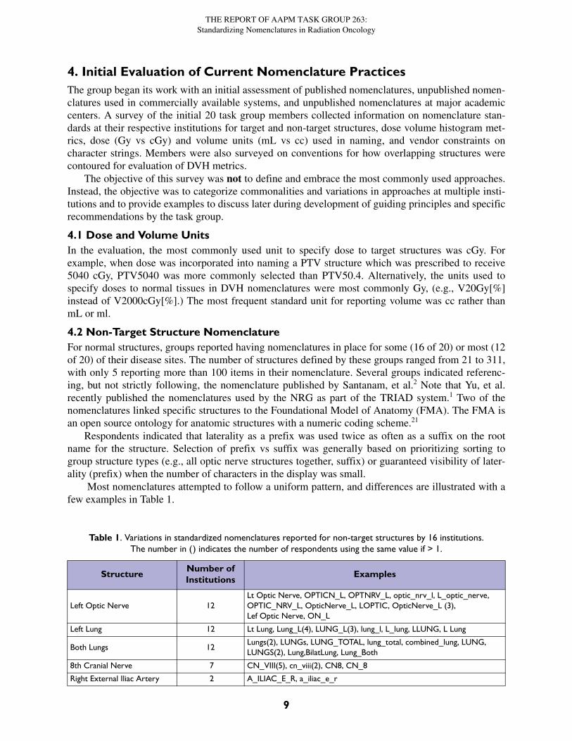
4.2 Non-Target Structure NomenclatureFor normal structures, groups reported having nomenclatures in place for some (16 of 20) or most (12of 20) of their disease sites. The number of structures defined by these groups ranged from 21 to 311,with only 5 reporting more than 100 items in their nomenclature. Several groups indicated referenc-ing, but not strictly following, the nomenclature published by Santanam, et al.2 Note that Yu, et al.recently published the nomenclatures used by the NRG as part of the TRIAD system.1 Two of thenomenclatures linked specific structures to the Foundational Model of Anatomy (FMA). The FMA isan open source ontology for anatomic structures with a numeric coding scheme.21
Respondents indicated that laterality as a prefix was used twice as often as a suffix on the rootname for the structure. Selection of prefix vs suffix was generally based on prioritizing sorting togroup structure types (e.g., all optic nerve structures together, suffix) or guaranteed visibility of later-ality (prefix) when the number of characters in the display was small.
Most nomenclatures attempted to follow a uniform pattern, and differences are illustrated with afew examples in Table 1.
Table 1. Variations in standardized nomenclatures reported for non-target structures by 16 institutions.The number in () indicates the number of respondents using the same value if > 1.
StructureNumber of Institutions
Examples
Left Optic Nerve 12Lt Optic Nerve, OPTICN_L, OPTNRV_L, optic_nrv_l, L_optic_nerve, OPTIC_NRV_L, OpticNerve_L, LOPTIC, OpticNerve_L (3), Lef Optic Nerve, ON_L
Left Lung 12 Lt Lung, Lung_L(4), LUNG_L(3), lung_l, L_lung, LLUNG, L Lung
Both Lungs 12Lungs(2), LUNGs, LUNG_TOTAL, lung_total, combined_lung, LUNG, LUNGS(2), Lung,BilatLung, Lung_Both
8th Cranial Nerve 7 CN_VIII(5), cn_viii(2), CN8, CN_8
Right External Iliac Artery 2 A_ILIAC_E_R, a_iliac_e_r
9
THE REPORT OF AAPM TASK GROUP 263:Standardizing Nomenclatures in Radiation Oncology
Convergence was greatest for simple structures requiring few characters (e.g., heart or HEART).Variations increased as the number of characters required to represent the structure increased; techni-cal limitations on character strings displayed by the different vendors, and local preferences for capi-talizations and separation of elements by spaces, underscores, or combinations of upper and lowercase characters, were the main reasons for variations in nomenclature. Most groups had creatednomenclatures for common structures (left lung) but had not developed a consistent naming strategyfor a more comprehensive list of structures (right external iliac artery).
4.3 Nomenclature for Target Structures
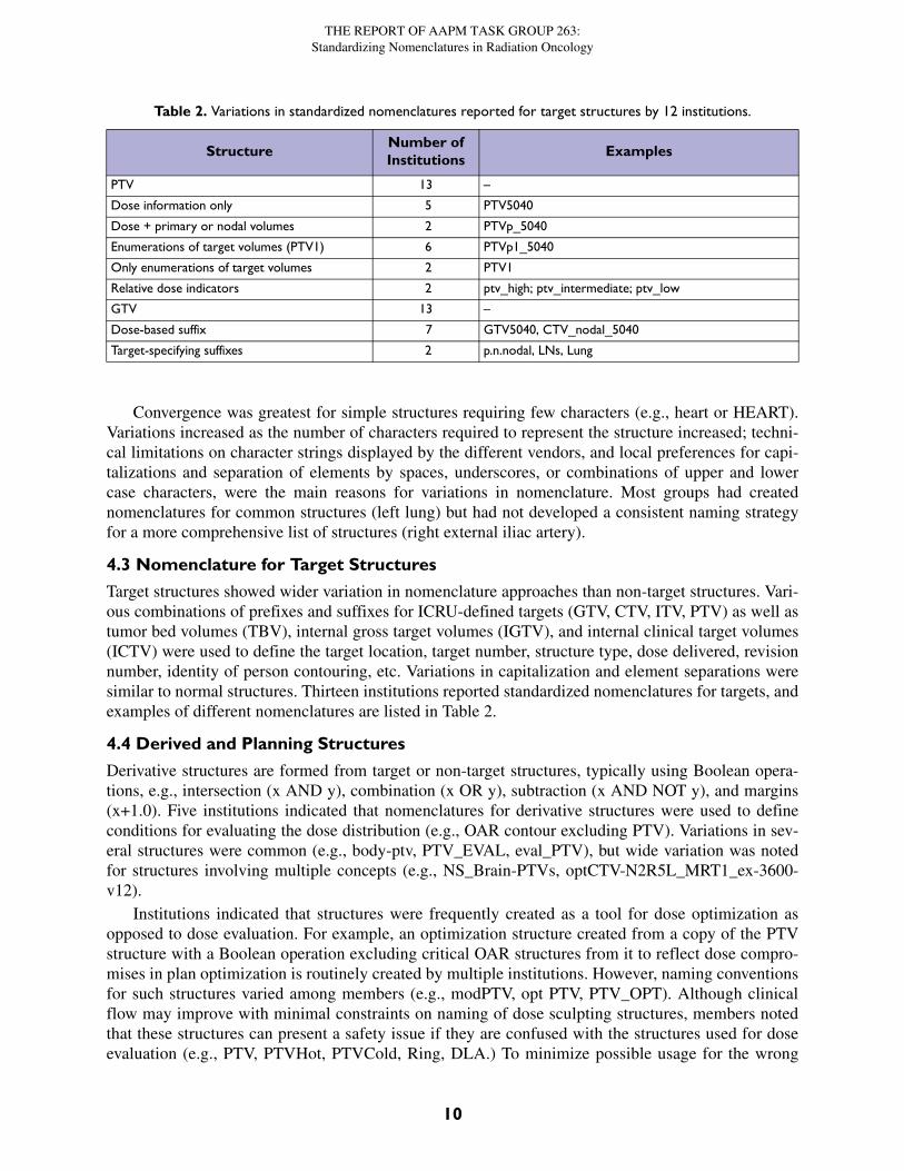
Target structures showed wider variation in nomenclature approaches than non-target structures. Vari-ous combinations of prefixes and suffixes for ICRU-defined targets (GTV, CTV, ITV, PTV) as well astumor bed volumes (TBV), internal gross target volumes (IGTV), and internal clinical target volumes(ICTV) were used to define the target location, target number, structure type, dose delivered, revisionnumber, identity of person contouring, etc. Variations in capitalization and element separations weresimilar to normal structures. Thirteen institutions reported standardized nomenclatures for targets, andexamples of different nomenclatures are listed in Table 2.
4.4 Derived and Planning Structures
Derivative structures are formed from target or non-target structures, typically using Boolean opera-tions, e.g., intersection (x AND y), combination (x OR y), subtraction (x AND NOT y), and margins(x+1.0). Five institutions indicated that nomenclatures for derivative structures were used to defineconditions for evaluating the dose distribution (e.g., OAR contour excluding PTV). Variations in sev-eral structures were common (e.g., body-ptv, PTV_EVAL, eval_PTV), but wide variation was notedfor structures involving multiple concepts (e.g., NS_Brain-PTVs, optCTV-N2R5L_MRT1_ex-3600-v12).
Institutions indicated that structures were frequently created as a tool for dose optimization asopposed to dose evaluation. For example, an optimization structure created from a copy of the PTVstructure with a Boolean operation excluding critical OAR structures from it to reflect dose compro-mises in plan optimization is routinely created by multiple institutions. However, naming conventionsfor such structures varied among members (e.g., modPTV, opt PTV, PTV_OPT). Although clinicalflow may improve with minimal constraints on naming of dose sculpting structures, members notedthat these structures can present a safety issue if they are confused with the structures used for doseevaluation (e.g., PTV, PTVHot, PTVCold, Ring, DLA.) To minimize possible usage for the wrong
Table 2. Variations in standardized nomenclatures reported for target structures by 12 institutions.
StructureNumber of Institutions
Examples
PTV 13 –
Dose information only 5 PTV5040
Dose + primary or nodal volumes 2 PTVp_5040
Enumerations of target volumes (PTV1) 6 PTVp1_5040
Only enumerations of target volumes 2 PTV1
Relative dose indicators 2 ptv_high; ptv_intermediate; ptv_low
GTV 13 –
Dose-based suffix 7 GTV5040, CTV_nodal_5040
Target-specifying suffixes 2 p.n.nodal, LNs, Lung
10
THE REPORT OF AAPM TASK GROUP 263:Standardizing Nomenclatures in Radiation Oncology
purpose, several institutions selected a single character (e.g., ‘z’ or ‘_’) that was uniformly applied asa prefix to those structures. This prefix ensured that in an alphabetical sort they appeared at the end orbeginning of the list (e.g., PTV, zPTVHot, zPTVCold, zRing, zDLA). Selection of z as a prefix issuggested.
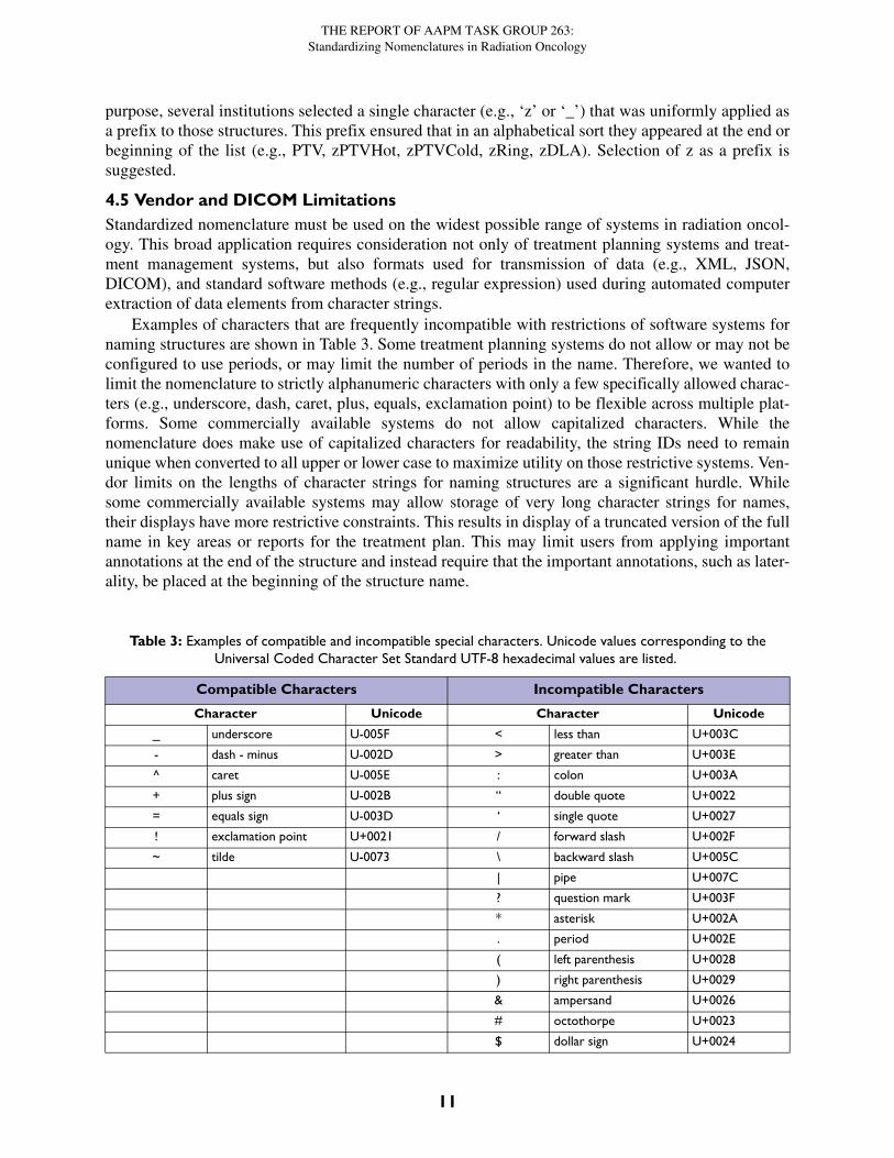
4.5 Vendor and DICOM Limitations Standardized nomenclature must be used on the widest possible range of systems in radiation oncol-ogy. This broad application requires consideration not only of treatment planning systems and treat-ment management systems, but also formats used for transmission of data (e.g., XML, JSON,DICOM), and standard software methods (e.g., regular expression) used during automated computerextraction of data elements from character strings.
Examples of characters that are frequently incompatible with restrictions of software systems fornaming structures are shown in Table 3. Some treatment planning systems do not allow or may not beconfigured to use periods, or may limit the number of periods in the name. Therefore, we wanted tolimit the nomenclature to strictly alphanumeric characters with only a few specifically allowed charac-ters (e.g., underscore, dash, caret, plus, equals, exclamation point) to be flexible across multiple plat-forms. Some commercially available systems do not allow capitalized characters. While thenomenclature does make use of capitalized characters for readability, the string IDs need to remainunique when converted to all upper or lower case to maximize utility on those restrictive systems. Ven-dor limits on the lengths of character strings for naming structures are a significant hurdle. Whilesome commercially available systems may allow storage of very long character strings for names,their displays have more restrictive constraints. This results in display of a truncated version of the fullname in key areas or reports for the treatment plan. This may limit users from applying importantannotations at the end of the structure and instead require that the important annotations, such as later-ality, be placed at the beginning of the structure name.
Table 3: Examples of compatible and incompatible special characters. Unicode values corresponding to the Universal Coded Character Set Standard UTF-8 hexadecimal values are listed.
Compatible Characters Incompatible Characters
Character Unicode Character Unicode
_ underscore U-005F < less than U+003C
- dash - minus U-002D > greater than U+003E
^ caret U-005E : colon U+003A
+ plus sign U-002B “ double quote U+0022
= equals sign U-003D ‘ single quote U+0027
! exclamation point U+0021 / forward slash U+002F
~ tilde U-0073 \ backward slash U+005C
| pipe U+007C
? question mark U+003F
* asterisk U+002A
. period U+002E
( left parenthesis U+0028
) right parenthesis U+0029
& ampersand U+0026
# octothorpe U+0023
$ dollar sign U+0024
11
THE REPORT OF AAPM TASK GROUP 263:Standardizing Nomenclatures in Radiation Oncology
5. Existing StandardsThe task group investigated existing standardizations frequently discussed in the context of radiationoncology nomenclature. Among these are ontologies which provide a framework for defining con-cepts and interrelationships intended for use in machine learning applications. These are not sufficientfor the needs of a clinical radiation oncology nomenclature since they do not accommodate many ofthe practical issues outlined in section 2.4. Better understanding of what these ontologies are assists inunderstanding how linkage of the nomenclature to the ontologies, where possible, improves interoper-ability and incorporation into the wider health care informatics community.
These and other standardized terminologies and ontologies relevant to the work of the task groupcan be accessed at the BioPortal website maintained by the National Center for Biomedical Ontology,at http://bioportal.bioontology.org/ontologies.
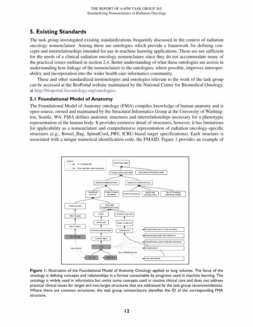
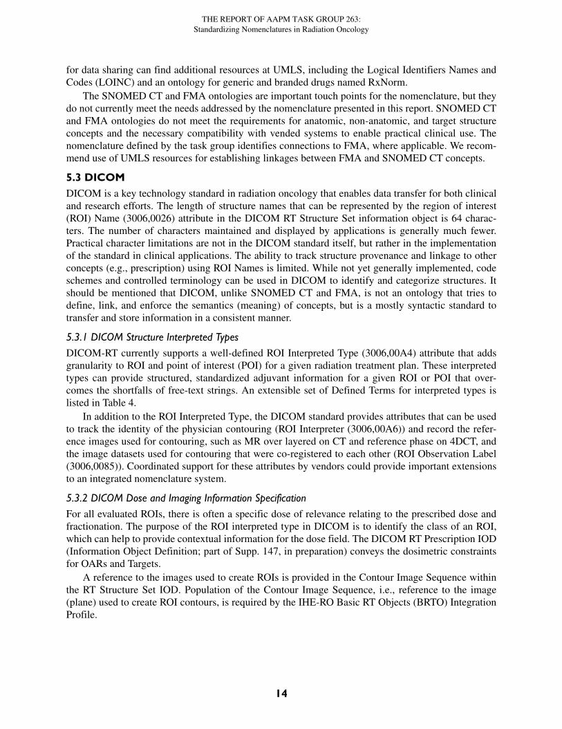
5.1 Foundational Model of AnatomyThe Foundational Model of Anatomy ontology (FMA) compiles knowledge of human anatomy and isopen-source, owned and maintained by the Structural Informatics Group at the University of Washing-ton, Seattle, WA. FMA defines anatomic structures and interrelationships necessary for a phenotypicrepresentation of the human body. It provides extensive detail of structures; however, it has limitationsfor applicability as a nomenclature and comprehensive representation of radiation oncology-specificstructures (e.g., Bowel_Bag, SpinalCord_PRV, ICRU-based target specifications). Each structure isassociated with a unique numerical identification code, the FMAID. Figure 1 provides an example of
Figure 1. Illustration of the Foundational Model of Anatomy Ontology applied to lung volumes. The focus of theontology is defining concepts and relationships in a format consumable by programs used in machine learning. Theontology is widely used in informatics but omits some concepts used in routine clinical care and does not addresspractical clinical issues for target and non-target structures that are addressed by the task group recommendations.Where there are common structures, the task group nomenclature identifies the ID of the corresponding FMAstructure.
12
THE REPORT OF AAPM TASK GROUP 263:Standardizing Nomenclatures in Radiation Oncology
portions of the FMA class hierarchy related to the lungs (FMAIDs not shown). In the group’s recom-mendation for nomenclature, the FMA identification code (FMAID) which most closely matches eachitem is also specified. The FMA may be accessed on-line at the NIH BioPortal at http://bioportal.bio-ontology.org/ontologies/FMA or at the University of Washington (Seattle, WA) website at http://xiphoid.biostr.washington.edu/fma/index.html.
5.2 SNOMED CT
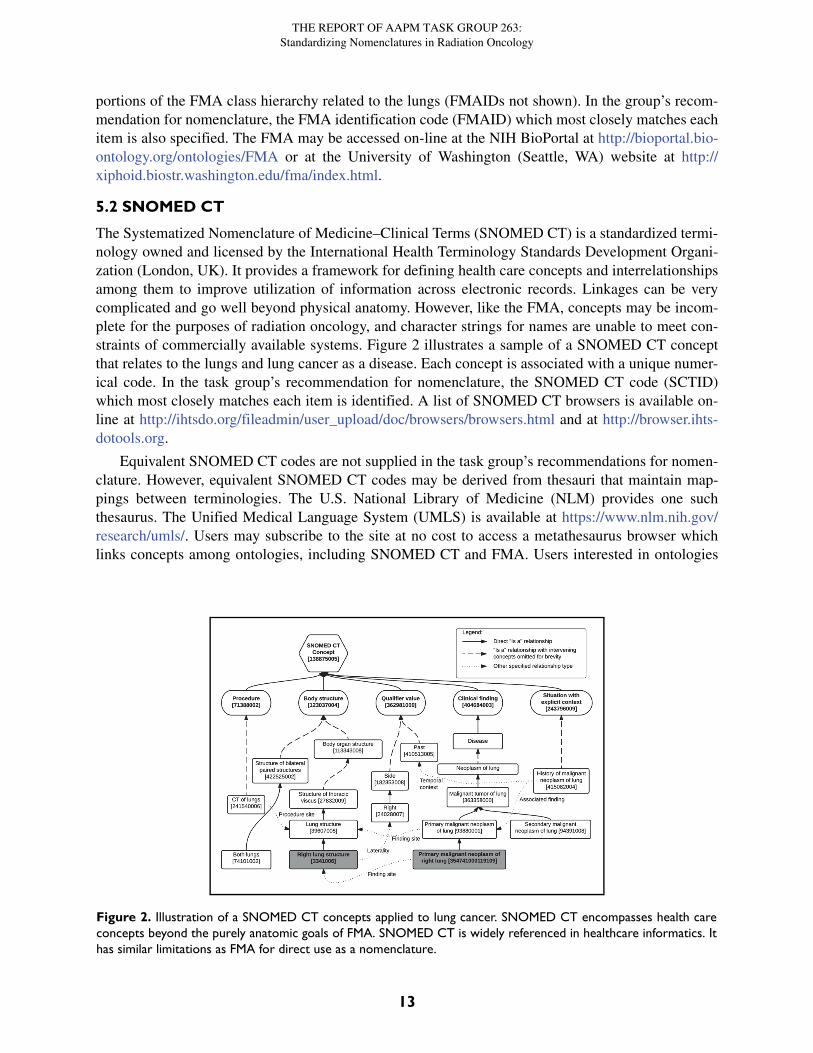
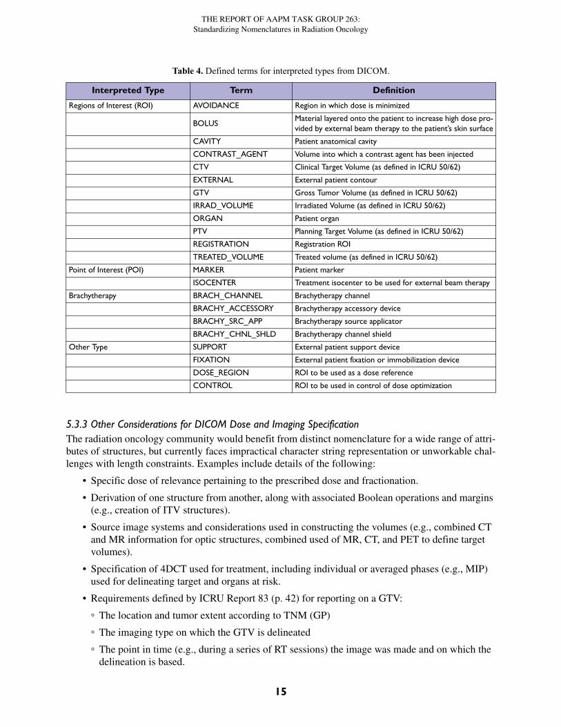
The Systematized Nomenclature of Medicine–Clinical Terms (SNOMED CT) is a standardized termi-nology owned and licensed by the International Health Terminology Standards Development Organi-zation (London, UK). It provides a framework for defining health care concepts and interrelationshipsamong them to improve utilization of information across electronic records. Linkages can be verycomplicated and go well beyond physical anatomy. However, like the FMA, concepts may be incom-plete for the purposes of radiation oncology, and character strings for names are unable to meet con-straints of commercially available systems. Figure 2 illustrates a sample of a SNOMED CT conceptthat relates to the lungs and lung cancer as a disease. Each concept is associated with a unique numer-ical code. In the task group’s recommendation for nomenclature, the SNOMED CT code (SCTID)which most closely matches each item is identified. A list of SNOMED CT browsers is available on-line at http://ihtsdo.org/fileadmin/user_upload/doc/browsers/browsers.html and at http://browser.ihts-dotools.org.
Equivalent SNOMED CT codes are not supplied in the task group’s recommendations for nomen-clature. However, equivalent SNOMED CT codes may be derived from thesauri that maintain map-pings between terminologies. The U.S. National Library of Medicine (NLM) provides one suchthesaurus. The Unified Medical Language System (UMLS) is available at https://www.nlm.nih.gov/research/umls/. Users may subscribe to the site at no cost to access a metathesaurus browser whichlinks concepts among ontologies, including SNOMED CT and FMA. Users interested in ontologies
Figure 2. Illustration of a SNOMED CT concepts applied to lung cancer. SNOMED CT encompasses health careconcepts beyond the purely anatomic goals of FMA. SNOMED CT is widely referenced in healthcare informatics. Ithas similar limitations as FMA for direct use as a nomenclature.
13
THE REPORT OF AAPM TASK GROUP 263:Standardizing Nomenclatures in Radiation Oncology
for data sharing can find additional resources at UMLS, including the Logical Identifiers Names andCodes (LOINC) and an ontology for generic and branded drugs named RxNorm.
The SNOMED CT and FMA ontologies are important touch points for the nomenclature, but theydo not currently meet the needs addressed by the nomenclature presented in this report. SNOMED CTand FMA ontologies do not meet the requirements for anatomic, non-anatomic, and target structureconcepts and the necessary compatibility with vended systems to enable practical clinical use. Thenomenclature defined by the task group identifies connections to FMA, where applicable. We recom-mend use of UMLS resources for establishing linkages between FMA and SNOMED CT concepts.
5.3 DICOMDICOM is a key technology standard in radiation oncology that enables data transfer for both clinicaland research efforts. The length of structure names that can be represented by the region of interest(ROI) Name (3006,0026) attribute in the DICOM RT Structure Set information object is 64 charac-ters. The number of characters maintained and displayed by applications is generally much fewer.Practical character limitations are not in the DICOM standard itself, but rather in the implementationof the standard in clinical applications. The ability to track structure provenance and linkage to otherconcepts (e.g., prescription) using ROI Names is limited. While not yet generally implemented, codeschemes and controlled terminology can be used in DICOM to identify and categorize structures. Itshould be mentioned that DICOM, unlike SNOMED CT and FMA, is not an ontology that tries todefine, link, and enforce the semantics (meaning) of concepts, but is a mostly syntactic standard totransfer and store information in a consistent manner.
5.3.1 DICOM Structure Interpreted TypesDICOM-RT currently supports a well-defined ROI Interpreted Type (3006,00A4) attribute that addsgranularity to ROI and point of interest (POI) for a given radiation treatment plan. These interpretedtypes can provide structured, standardized adjuvant information for a given ROI or POI that over-comes the shortfalls of free-text strings. An extensible set of Defined Terms for interpreted types islisted in Table 4.
In addition to the ROI Interpreted Type, the DICOM standard provides attributes that can be usedto track the identity of the physician contouring (ROI Interpreter (3006,00A6)) and record the refer-ence images used for contouring, such as MR over layered on CT and reference phase on 4DCT, andthe image datasets used for contouring that were co-registered to each other (ROI Observation Label(3006,0085)). Coordinated support for these attributes by vendors could provide important extensionsto an integrated nomenclature system.
5.3.2 DICOM Dose and Imaging Information SpecificationFor all evaluated ROIs, there is often a specific dose of relevance relating to the prescribed dose andfractionation. The purpose of the ROI interpreted type in DICOM is to identify the class of an ROI,which can help to provide contextual information for the dose field. The DICOM RT Prescription IOD(Information Object Definition; part of Supp. 147, in preparation) conveys the dosimetric constraintsfor OARs and Targets.
A reference to the images used to create ROIs is provided in the Contour Image Sequence withinthe RT Structure Set IOD. Population of the Contour Image Sequence, i.e., reference to the image(plane) used to create ROI contours, is required by the IHE-RO Basic RT Objects (BRTO) IntegrationProfile.
14
THE REPORT OF AAPM TASK GROUP 263:Standardizing Nomenclatures in Radiation Oncology
5.3.3 Other Considerations for DICOM Dose and Imaging SpecificationThe radiation oncology community would benefit from distinct nomenclature for a wide range of attri-butes of structures, but currently faces impractical character string representation or unworkable chal-lenges with length constraints. Examples include details of the following:
• Specific dose of relevance pertaining to the prescribed dose and fractionation.
• Derivation of one structure from another, along with associated Boolean operations and margins (e.g., creation of ITV structures).
• Source image systems and considerations used in constructing the volumes (e.g., combined CT and MR information for optic structures, combined used of MR, CT, and PET to define target volumes).
• Specification of 4DCT used for treatment, including individual or averaged phases (e.g., MIP) used for delineating target and organs at risk.
• Requirements defined by ICRU Report 83 (p. 42) for reporting on a GTV:
◦ The location and tumor extent according to TNM (GP)
◦ The imaging type on which the GTV is delineated
◦ The point in time (e.g., during a series of RT sessions) the image was made and on which the delineation is based.
Table 4. Defined terms for interpreted types from DICOM.
Interpreted Type Term Definition
Regions of Interest (ROI) AVOIDANCE Region in which dose is minimized
BOLUSMaterial layered onto the patient to increase high dose pro-vided by external beam therapy to the patient’s skin surface
CAVITY Patient anatomical cavity
CONTRAST_AGENT Volume into which a contrast agent has been injected
CTV Clinical Target Volume (as defined in ICRU 50/62)
EXTERNAL External patient contour
GTV Gross Tumor Volume (as defined in ICRU 50/62)
IRRAD_VOLUME Irradiated Volume (as defined in ICRU 50/62)
ORGAN Patient organ
PTV Planning Target Volume (as defined in ICRU 50/62)
REGISTRATION Registration ROI
TREATED_VOLUME Treated volume (as defined in ICRU 50/62)
Point of Interest (POI) MARKER Patient marker
ISOCENTER Treatment isocenter to be used for external beam therapy
Brachytherapy BRACH_CHANNEL Brachytherapy channel
BRACHY_ACCESSORY Brachytherapy accessory device
BRACHY_SRC_APP Brachytherapy source applicator
BRACHY_CHNL_SHLD Brachytherapy channel shield
Other Type SUPPORT External patient support device
FIXATION External patient fixation or immobilization device
DOSE_REGION ROI to be used as a dose reference
CONTROL ROI to be used in control of dose optimization
15
THE REPORT OF AAPM TASK GROUP 263:Standardizing Nomenclatures in Radiation Oncology
6. Color Specification
The task group survey investigated whether or not standard colors were used for structure templatesand DVH curves. The selection of specific colors and display parameters (e.g., filled-in, semi-trans-parent, wire-contour) was highly variable among institutions. Standard coloration of structures atinstitutions facilitated plan quality assurance (QA) and interpretation of plans for peer review and doc-umentation. However, standardization of the colors across institutions is not easily achievablebecause:
1. Treatment planning and plan review systems have limited and variable color options.
2. Visibility of contours overlaid on tissues on CT images depends on the density of the con-toured structure and the density of the surrounding structures. Even if the colors are appropri-ate for CT images, the transferred or displayed colors on a different modality may not be visible anymore.
3. Visibility of contours also depends on the dose display (isodose lines or color wash). For example, different colors are needed to distinguish the two—the target and the prescription isodose line. Note that color-blind people make up 10% of a population. Different formats (solid line vs dashed line) should also be considered to improve visibility.
4. Visual perception of reviewers differs.
Standardization of colors was seen as valuable, but notions of the “right” color were highly vari-able. The task group elected not to make specific recommendations for colors at this point in timebecause (1) specific color coding is not currently necessary to improve the ability to automateexchange of data among institutions, (2) there are challenges as outlined above, and (3) there is cur-rently a lack of uniformity among clinical trials on this parameter. In general, institutions can improvesafety and consistency by defining and implementing simple rules for the use of color to make plansmore easily interpretable. Using similar colors for isodose lines and structures when the dose abuts thestructure is not recommended. As the nomenclature is adopted into clinical practice and trials toenable sharing of standardized templates and scripts that reduce work, convergence on expectationsfor color will begin to occur implicitly.
7. Recommendations for Non-Target Structure Nomenclature
7.1 Approach
TG-263 defined the following set of guiding principles for creating structure names. As new structuresare added, following these principles ensures names that are operable with current vended systems andconsistent in structure. This enables the use of computer algorithms to parse names.
The primary objective in defining a nomenclature is to reduce variability in naming. Variation isthe principle barrier to developing automated solutions for accurate extraction, exchange, and process-ing of data. Variation in naming occurs over time between individuals and among institutions and ven-dors. The second objective for a nomenclature is straightforward adoption into current practice. Forexample, the use of just three hexadecimal characters would enable numeric coding of 4096 struc-tures, leaving ample room to encode other details about the structures and to also be language neutral.However, proposing that users label the brain as “06E” instead of “Brain” would fail, utterly. To suc-ceed in reducing data variability while being practical, there were a few situations where it was neces-sary to sacrifice internal consistency or strict adherence to a set of ideals in order to define a pragmaticschema.
16
THE REPORT OF AAPM TASK GROUP 263:Standardizing Nomenclatures in Radiation Oncology
7.2 Guiding Principles for Non-Target Nomenclature1. All structure names are limited to 16 characters or fewer to ensure compatibility with a major-
ity of vended systems.
2. All structure names must resolve to unique values, independent of capitalization. This ensures that systems with case-insensitive formats do not result in overlapping definitions.
3. Compound structures are identified using the plural, i.e., the name ends with an ‘s’ or an ‘i’ as appropriate on the root structure name (e.g., Lungs, Kidneys, Hippocampi, LNs (for all lymph nodes), Ribs_L.)
4. The first character of each structure category is capitalized (e.g., Femur_Head, Ears_Exter-nal).
5. No spaces are used.
6. An underscore character is used to separate categorizations (e.g., Bowel_Bag).
7. Spatial categorizations for the primary name are always located at the end of the string follow-ing an underscore character (e.g., Lung_L, Lung_LUL, Lung_RLL, OpticNrv_PRV03_L):
a. L for left
b. R for Right
c. A for Anterior
d. P for Posterior
e. I for Inferior
f. S for Superior
g. RUL, RLL, RML for right upper, lower and middle lobe
h. LUL, LLL for left upper and lower lobe
i. NAdj for non-adjacent
j. Dist for distal, Prox for proximal
8. A consistent root structure name is used for all substructures (e.g., SeminalVes and Semi-nalVes_Dist have a consistent root structure name, but SeminalVesicle and SemVes_Dist do not have a consistent root structure name).
9. Standard category roots are used for structures distributed throughout the body:
a. A for artery (e.g., A_Aorta, A_Carotid)
b. V for vein (e.g., V_Portal, V_Pulmonary)
c. LN for lymph node (e.g., LN_Ax_L1, LN_IMN)
d. CN for cranial nerve (e.g., CN_IX_L, CN_XII_R)
e. Glnd for glandular structure (e.g., Glnd_Submand)
f. Bone (e.g., Bone_Hyoid, Bone_Pelvic)
g. Musc for muscle (e.g., Musc_Masseter, Musc_Sclmast_L)
h. Spc for Space (e.g., Spc_Bowel, Spc_Retrophar_L)
i. VB for vertebral body
j. Sinus for sinus (e.g., Sinus_Frontal, Sinus_Maxillary)
17
THE REPORT OF AAPM TASK GROUP 263:Standardizing Nomenclatures in Radiation Oncology
10. Planning organ at risk volumes (PRV) are indicated with PRV following the main structure separated by an underscore (e.g., Brainstem_PRV). Optionally, the uniform expansion used to form the PRV from the main structure in millimeters is indicated with two numerals (e.g., Spi-nalCord_PRV05, Brainstem_PRV03),) unless the result exceeds the character limit. For exam-ple, OpticChiasm_PRV03 is 17 characters and may be truncated to OpticChiasm_PRV3.
11. Partial structures are designated by appending a ‘~’ character to the root name (e.g., Brain~, Lung~_L). This designator should be used to ensure a contoured structure is not misinter-preted as a whole organ when such a misinterpretation could have clinical implications (typi-cally parallel organs). A use case example is a CT scan not long enough to include the full lung volumes, for which Lungs~ indicates the contoured pair of lungs is only a portion of the complete structure.
12. If a custom qualifier string is to be used, it is placed at the end after a ‘^’ character (e.g., Lungs^Ex).
13. Establish a Primary and a Reverse Order name for each structure.
a. Primary Name. Reading left to right, the structure categorization proceeds from general to specific with laterality on the end. As a result, alphabetically sorted structure names pro-duce a list that is grouped by organ (e.g., Kidney_R, Kidney_Cortex_L, Kidney_Hi-lum_R). The Primary Name is recommended as the standard choice.
b. Reverse Order Name. Reverse the order of Primary Name. Some vended systems allow longer strings but have displays that default to show fewer than 16 characters. The Reverse Order Name increases the likelihood that sufficient information can be displayed to safely identify the correct structure. For example, R_Hilum_Kidney would display as R_Hi-lum_Ki if the vendor’s report only showed the first 10 characters. It is suggested that Reverse Order Name be limited to situations where vendor system constraints prevent safe use of Primary Name.
14. Camel case (a compound word where each word starts with a capital letter and there is no space between words such as CamelCase) is only used when a structure name implies two concepts, but the concepts do not appear as distinct categories in common usage (e.g., Cau-daEquina instead of Cauda_Equina) because there are not several examples of Cauda_xxxxx. Camel case names for primary and reverse order names are identical.
15. Structures that are not used for dose evaluation (e.g., optimization structures, high/low dose regions) should be prefixed with a ‘z’ or ‘_’ character so that an alphabetical sort groups them away from structures that are used for dose evaluation (e.g., zPTVopt). Selection of ‘z’ to des-ignate dose evaluation structures is suggested.
Very few vendor systems do not allow capital letters in the fields identifying structures. Since thevast majority do, capitalization was used as part of the guiding principles (item 4). Item 2 assures thatif a system does not allow capitalization, the character string will still be unique and can be program-matically matched.
Potential conflicts for the use of ‘A’ in indicating an arterial structure and in indicating an anteriorportion of a structure (e.g., A_Carotid_A) were noted and discussed. In practice, the need to identifyan anterior surface is rare. For example, NRG currently does not make use of this descriptor for any ofits trials. Alternative spatial designators either presented similar issues (e.g., D for dorsal and V forventral) or violated standard medical practices (e.g., F for front and B for back). Use of alternativeindicators for artery and vein were also discussed. The use of A and V to indicate artery and vein is in
18
THE REPORT OF AAPM TASK GROUP 263:Standardizing Nomenclatures in Radiation Oncology
wide use, and no single character alternatives were evident. Since no examples existed with this poten-tial conflict, the group elected to accept the potential conflict for the current version of the guidelines.
Permitting the use of camel case for a few specific structures was discussed. In Primary Name val-ues, concepts are ordered from general to specific, proceeding left to right. Reverse Order Name val-ues invert the ordering, e.g., Bag_Bowel for Primary Name and Bowel_Bag for Reverse Order Name.The utilization of camel case provided a means to not violate this principle and maintain compatibilitywith common usage for the relatively small number of structures involved (e.g., CaudaEquina andOpticChiasm are rendered the same for both Primary Name and Reverse Order Name). The potentialsafety impact of this usage of camel case was considered. No major risks were identified, and thegroup felt that assuring the same value of both name values for those few special cases was seen assupporting patient safety.
Whether or not to allow for two naming values for each structure was considered from a practicalperspective. The recommended standard is the Primary Name. Vendors are encouraged to modify theirsystems so that the full 16-character lengths of standard structure names are displayed in applicationsand reports. Reverse Order Name values are only for those systems unable to support the PrimaryName values until further changes are made in those systems. As these changes are made and safetyrisks introduced by concatenating names eliminated, usage should converge on the Primary Name.
In evaluating treatment plan dose distributions, tolerance levels are determined by tissue or organtype. By using standard category root names, an alphabetic sort of the Primary Name structures willgroup those with similar tolerances. This is particularly valuable when structure names may not becommonly used and could be at risk for misinterpreting the structure type (e.g., Mesenteric vs A_Mes-enteric, Illiac vs A_Illiac, or I vs CN_I). However, there are a few structures that are in routine usewhere forcing use of the category root name could impede adoption (e.g., Parotid vs Glnd_Parotid) ofthe nomenclature. In those few cases, the task group chose to accept the internal inconsistency of for-going the root name (e.g., Parotid) in order to maintain the overarching objectives of reducing variabil-ity in nomenclature and high adoptability into clinical practice.
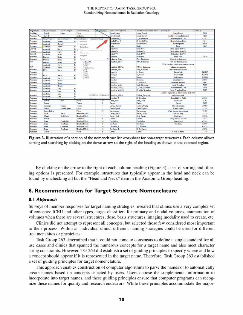
7.3 Structure Nomenclature ListA spreadsheet was created to facilitate look up of structures. Structures were categorized, described,and assigned official values and linked to the corresponding Foundations of Medical Anatomy identi-fication number (FMAID). Currently, the nomenclature defines 717 structures. The complete list canbe found on the AAPM website for TG-263 at http://www.aapm.org/pubs/reports/RPT_263_Supple-mental/.
The list will be a living document with periodic updates. In addition, all guidelines for structurenaming and for DVH metrics are included in the document.
There are nine column headings in the spreadsheet used to aid in finding the names of structures ofinterest:
1. Target Type: Anatomic, Non-Anatomic (e.g., catheter), Derived (e.g., Body-PTV)
2. Major Category: General organ category
3. Minor Category: Additional distinguishing category
4. Anatomic Group: Region of the body where structure is located
5. N Characters: Number of characters in the name
6. TG263–Primary Name: Preferred naming
7. TG263–Reverse Order Name: Alternative naming
8. Description: Additional description of the structure
9. FMAID: Identification number of structure in the FMA most closely related
19
THE REPORT OF AAPM TASK GROUP 263:Standardizing Nomenclatures in Radiation Oncology
By clicking on the arrow to the right of each column heading (Figure 3), a set of sorting and filter-ing options is presented. For example, structures that typically appear in the head and neck can befound by unchecking all but the “Head and Neck” item in the Anatomic Group heading.
8. Recommendations for Target Structure Nomenclature
8.1 ApproachSurveys of member responses for target naming strategies revealed that clinics use a very complex setof concepts: ICRU and other types, target classifiers for primary and nodal volumes, enumeration ofvolumes when there are several structures, dose, basis structures, imaging modality used to create, etc.
Clinics did not attempt to represent all concepts, but selected those few considered most importantto their process. Within an individual clinic, different naming strategies could be used for differenttreatment sites or physicians.
Task Group 263 determined that it could not come to consensus to define a single standard for alluse cases and clinics that spanned the numerous concepts for a target name and also meet characterstring constraints. However, TG-263 did establish a set of guiding principles to specify where and howa concept should appear if it is represented in the target name. Therefore, Task Group 263 establisheda set of guiding principles for target nomenclature.
This approach enables construction of computer algorithms to parse the names or to automaticallycreate names based on concepts selected by users. Users choose the supplemental information toincorporate into target names, and these guiding principles ensure that computer programs can recog-nize these names for quality and research endeavors. While these principles accommodate the major-
Figure 3. Illustration of a section of the nomenclature list worksheet for non-target structures. Each column allowssorting and searching by clicking on the down arrow to the right of the heading as shown in the zoomed region.
20
THE REPORT OF AAPM TASK GROUP 263:Standardizing Nomenclatures in Radiation Oncology
ity of encountered names, they cannot accommodate all. TG-263 recommends using the ‘^’ characterto designate supplemental information not incorporated in the current guidelines.
8.2 Guiding Principles for Target Nomenclature
1. The first set of characters must be one of the allowed target types:
• GTV
• CTV
• ITV
• IGTV (Internal Gross Target Volume—gross disease with margin for motion)
• ICTV (Internal Clinical Target Volume—clinical disease with margin for motion)
• PTV
• PTV! for low-dose PTV volumes that exclude overlapping high-dose volumes (See the sec-tion discussing segmented vs non-segmented PTVs.)
2. If a target classifier is used, place the target classifier after the target type with no spaces. Allowed target classifiers are listed below:
• n: nodal (e.g., PTVn)
• p: primary (e.g., GTVp)
• sb: surgical bed (e.g., CTVsb)
• par: parenchyma (e.g., GTVpar)
• v:venous thrombosis (e.g., CTVv)
• vas: vascular (e.g., CTVvas)
3. If multiple spatially distinct targets are indicated, then Arabic numerals are used after the tar-get type + classifier (e.g., PTV1, PTV2, GTVp1, GTVp2).)
4. If designation of the imaging modality and sequential order in the image set need recording for adaptive therapy, then the nomenclature follows the type/classifier/enumerator with an underscore and then the image modality type (CT, PT, MR, SP) and number of the image in the sequence (e.g., PTVp1_CT1PT1, GTV_CT2).)
5. If structure indicators are used, they follow the type/classifier/enumerator/imaging with an underscore prefix and are values from the approved structure nomenclature list, (e.g., CTV_A_Aorta, CTV_A_Celiac, GTV_Preop, PTV_Boost, PTV_Eval, PTV_MR2_Prostate).
6. If dose is indicated, the dose is placed at the end of the target string prefixed with an under-score character.
• The task group strongly recommends using relative dose levels instead of specifying physical dose
◦ High (e.g., PTV_High, CTV_High, GTV_High)
◦ Low (e.g., PTV_Low, CTV_Low, GTV_Low)
◦ Mid: (e.g., PTV_Mid, CTV_Mid, GTV_Mid)
21
THE REPORT OF AAPM TASK GROUP 263:Standardizing Nomenclatures in Radiation Oncology
◦ Mid+2-digit enumerator: allows specification of more than three relative dose levels (e.g., PTV_Low, PTV_Mid01, PTV_Mid02, PTV_Mid03, PTV_High). Lower numbers corre-spond to lower dose values.
• If numeric values for the physical dose must be used, then specification of the numeric value of the dose in units of cGy is strongly recommended (e.g., PTV_5040).
• If numeric values for physical dose must be used and these must be specified in units of Gy, then ‘Gy’ should be appended to the numeric value of the dose (e.g., PTV_50.4Gy). For sys-tems that do not allow use of a period, the ‘p’ character should be substituted (e.g., PTV_50p4Gy)
7. If the dose indicated must reflect the number of fractions used to reach the total dose, then the numeric values of dose per fraction in cGy, or in Gy with the unit specifier, and number of fractions separated by an “x” character are added at the end (e.g., PTV_Liver_2000x3 or PTV_Liver_20Gyx3).
8. If the structure is cropped back from the external contour for the patient, then the quantity of cropping by “-xx” millimeters is placed at the end of the target string. The cropping length fol-lows the dose indicator, with the amount of cropping indicated by xx millimeters (e.g., PTV_Eval_7000-08, PTV-03, CTVp2-05).
9. If a custom qualifier string is used, the custom qualifier is placed at the end after a ‘^’ charac-ter (e.g., PTV^Physician1, GTV_Liver^ICG).)
10. If it is not possible to follow the guidelines and remain within the 16-character limit, then pre-serve the relative ordering but remove underscore characters, progressing from left to right as needed to meet the limit (e.g PTVLiverR_2000x3.) This last resort scenario undermines the use of automated tools.
Two distinct methods are used for sequential treatments of the same target volume (Guiding Prin-ciple #3). Some institutions used sequential numbers as the patient returns for future treatment coursesfor the same PTV, (e.g., PTV1 and PTV2 for the original course and PTV3 and PTV4 for lung metas-tasis treated in a later course). In contrast, other institutions numbered sequentially for targets treatedwithin the course, independent of historical treatments (e.g., PTV1 and PTV2 for the original courseand PTV1 and PTV2 for lung metastasis treated in a later course) used the same nomenclature for re-irradiation of the same (not spatially distinct) target. TG-263 does not define a recommended sequen-tial numbering method. Practices should ensure their method is self-consistent and guard against theincorrect summing of total doses.
Dose units used when categorizing target structures with dose information was extensively dis-cussed. As stated above, the primary objective for a nomenclature is to reduce variability. The second-ary objective is facilitating adoptability into clinical practice. Prescription of doses in units of cGy iscommon in the United States, is the current recommendation of the ASTRO working group on pre-scriptions, and is supported by analysis of RO-ILS data19. Prescription in units of Gy is more commonin European countries and is also used in some large institutions in the US. All groups advocating oneover the other cite safety as a primary factor. While it is highly desirable to specify a single answer inthe standard, the most important point for safety and data access is ensuring unambiguous communi-cation. Since it was not possible to identify a single dose unit with wide global adoption, an approachcompatible with each was identified.
The use of relative dose (e.g., PTV_High) was the primary recommendation if dose information isconveyed in the target name. This approach has several advantages. First, it is independent of thephysical dose units used at various institutions, so there is no need to specify cGy (e.g., PTV_6660) or
22
THE REPORT OF AAPM TASK GROUP 263:Standardizing Nomenclatures in Radiation Oncology
Gy (e.g PTV_66.6Gy). Second, it is not uncommon for a prescription to be changed in the course oftreating a patient. In that case, if physical dose units were used, the structure name would have to berenamed with the correct dose to convey the correct information (e.g., change from PTV_7560 toPTV_7380). Without this change, the name could convey conflicting information with respect to thecurrent prescription, presenting both logistic and safety issues. Third, when mining dosimetric data,relative dose names greatly improve the speed, accuracy, and composability of queries to extractneeded information. For most disease sites, only two or three target structure names are needed (e.g.,PTV_High, PTV_Mid, PTV_Low), so extracting the median dose to these structures, along with thenumber of fractions treated, provides a great deal of information on target structure doses with mini-mal effort. On the other hand, needing to first identify all dose levels from the structure name and thenreconstructing relative dose levels within each plan from the physical doses specified in the name ismuch more difficult and prone to error.
If physical doses are used, the numeric value should be defined in units of cGy. The use of cGy isconsistent with recommendations of ASTRO and RO-ILS. Enabling unambiguous standardized com-munication of dose in the name promotes adoptability of the nomenclature in a broad range of nationaland international clinics. For clinics that currently use Gy for prescriptions, then the physical doses inGy should be communicated explicitly with the addition of ‘Gy’ as a suffix for clarity in communica-tion. This approach uses a similar number of characters for each dose unit, and when Gy is used it isconsistent with the recommendations for DVH metrics, as described in the next section.
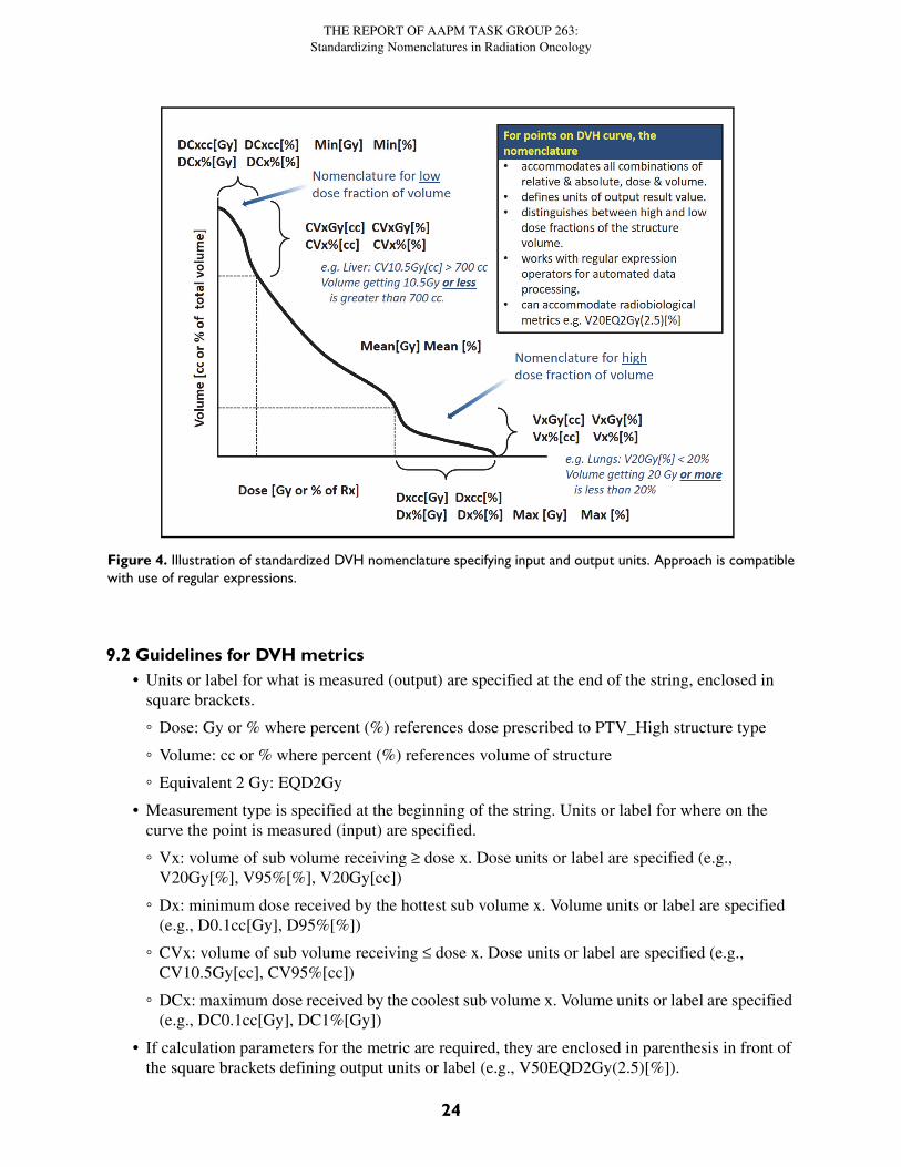
9. Recommendations for Dose Volume Histogram Metrics9.1 ApproachVery few examples of standardized nomenclatures exist for the full set of dose and volume metricsused in practice. Providing specificity on exactly what is measured, input parameters, units used fordose and volume—all in a format that can be parsed with regular expression operators—improves theability to use computer algorithms to automate calculation. The ability to incorporate radiobiologicalmetrics and units is also important. Figure 4 illustrates the recommended DVH nomenclature.
23
THE REPORT OF AAPM TASK GROUP 263:Standardizing Nomenclatures in Radiation Oncology
9.2 Guidelines for DVH metrics• Units or label for what is measured (output) are specified at the end of the string, enclosed in
square brackets.
◦ Dose: Gy or % where percent (%) references dose prescribed to PTV_High structure type
◦ Volume: cc or % where percent (%) references volume of structure
◦ Equivalent 2 Gy: EQD2Gy
• Measurement type is specified at the beginning of the string. Units or label for where on the curve the point is measured (input) are specified.
◦ Vx: volume of sub volume receiving ≥ dose x. Dose units or label are specified (e.g., V20Gy[%], V95%[%], V20Gy[cc])
◦ Dx: minimum dose received by the hottest sub volume x. Volume units or label are specified (e.g., D0.1cc[Gy], D95%[%])
◦ CVx: volume of sub volume receiving ≤ dose x. Dose units or label are specified (e.g., CV10.5Gy[cc], CV95%[cc])
◦ DCx: maximum dose received by the coolest sub volume x. Volume units or label are specified (e.g., DC0.1cc[Gy], DC1%[Gy])
• If calculation parameters for the metric are required, they are enclosed in parenthesis in front of the square brackets defining output units or label (e.g., V50EQD2Gy(2.5)[%]).
Figure 4. Illustration of standardized DVH nomenclature specifying input and output units. Approach is compatiblewith use of regular expressions.
24
THE REPORT OF AAPM TASK GROUP 263:Standardizing Nomenclatures in Radiation Oncology
Conventional DVH metrics correspond to points receiving a certain dose or more. In lung,V20Gy[%] is the percentage of lung volume that receives 20 Gy or more. Conversely, details aboutpoints receiving a certain dose or less use nomenclature with an inserted “C” for complement or coldto qualify the sub volume21. Thus for liver SBRT, CV15Gy[cc] is the absolute volume that receives15 Gy or less. For example, DC700cc[Gy] selects the 700 cc sub volume that receives the lowest over-all dose and reports the highest dose in that sub volume.
Task Group 263 discussed and acknowledged the differences in recommendation for use of cGydose units in defining target structure names (e.g., PTV_4500) compared to the recommendation foruse of Gy for DVH metrics (e.g., V20Gy[%] vs V2000cGy[%]). The nomenclature recommendationswere in keeping with routine clinical practice for many clinics and represented minimal deviationfrom less specific values commonly encountered in the literature (e.g., V20 vs V20Gy[%]). Further,while safety in minimizing risk of miscommunication about target volumes and allowed free text char-acters in vended systems was significant in the discussion of target structures (e.g., PTV_5040 vsPTV_50.4), these safety issues were not found for the DVH metrics. The nomenclature extends usespecification of input and output units with addition of the EQD2Gy dose unit specifying dose deliv-ered in 2 Gy fractions calculated to have the same radiobiological effect with the linear quadraticmodel and a specified value of α/β. Calculation parameter values, including α/β, are enclosed inparenthesis before the output units. Nomenclature does not currently specify the ordering of parametervalues for particular calculations. This approach minimizes naming constraints of the evolving typesof radiobiological calculations, or parameters used, while preserving a consistent representation ofinvolved units and explicit indication parameter values. Designation of algorithm may also beincluded as a parameter in the parenthesis.
Examples of radiobiological calculations using EQD2Gy are listed below:
• Maximum equivalent 2 Gy dose calculated with an α/β ratio of 4: Max(4)[EQD2Gy].
• Equivalent 2 Gy dose encompassing 90% of a target volume, calculated with an α/β ratio of 10: D90%(10)[EQD2Gy].
• Percentage volume of a structure receiving 50 EQD2Gy using an α/β of 3 vs 10: V50EQD2Gy(3)[%] vs V50EQD2Gy(10)[%].
• Distinguishing use of the linear-quadratic (LQ) vs the linear-quadratic-linear (LQL) model in calculating the 2Gy equivalent dose encompassing 95% of a structure when an α/β of 10 is used: D95%(10,LQ)[EQD2Gy] vs D95%(10,LQL)[EQD2Gy].
Research settings use a wide range of radiobiological metrics. Examples include Tumor ControlProbability (TCP), Normal Tissue Complication Probability (NTCP), and Biologically Effective Dose(BED). These are not typically encountered in clinical settings at this time. Models continue to evolvedefining new types and parameters. Approaches currently in use at several member institutions werecompatible with the guideline recommendations for enclosing calculation parameters in parenthesis(e.g., NTCP(LQL, α/β = 2.5, TD50 = 40, n = 1.0, m = 0.13), NTCP(40, 1.0, 0.13), BED(α/β = 10),BED(10).) The task group did not make specific nomenclature recommendations for these radiobio-logical metric types and parameters.
10. Recommendations for Distinguishing Metrics of Segmented vs Non-Segmented Target StructuresThe reported DVH metrics for multiple PTV volumes treated to differing dose levels should define ifthe lower-dose PTV volumes exclude (segmented) or include (non-segmented) the higher-dose PTVvolumes. For example, a low-dose nodal volume may be treated to 5000 cGy (PTV_5000), while a
25
THE REPORT OF AAPM TASK GROUP 263:Standardizing Nomenclatures in Radiation Oncology
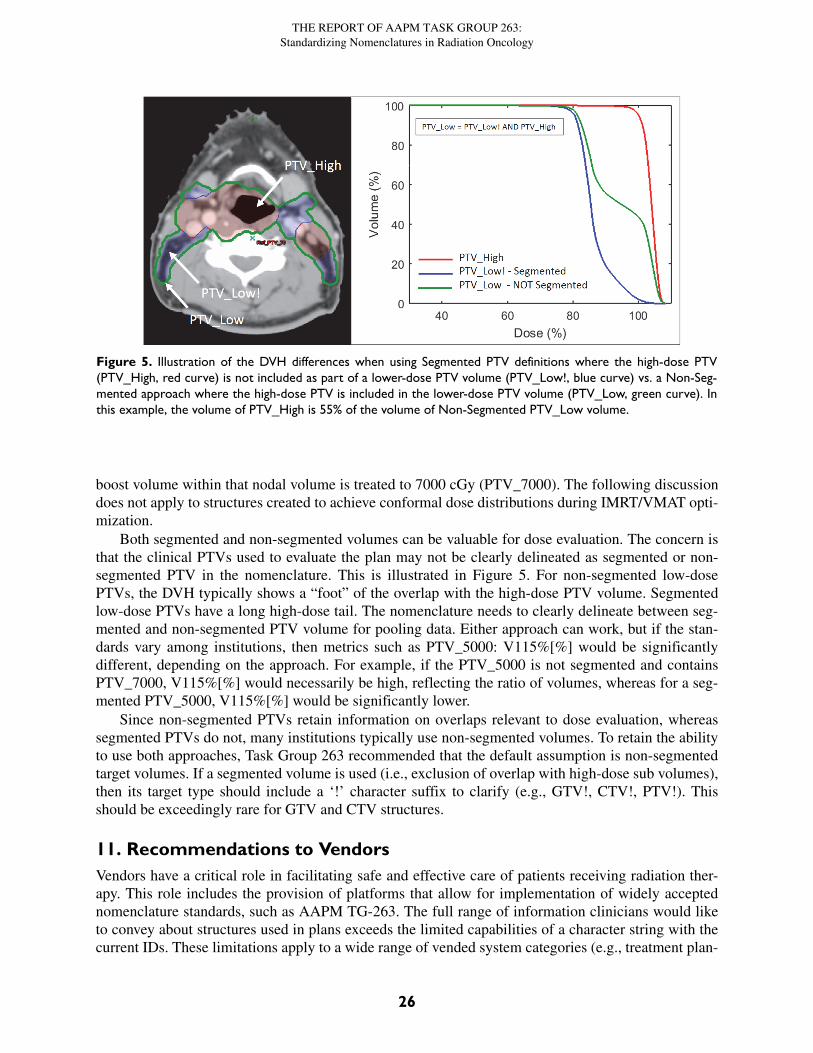
boost volume within that nodal volume is treated to 7000 cGy (PTV_7000). The following discussiondoes not apply to structures created to achieve conformal dose distributions during IMRT/VMAT opti-mization.
Both segmented and non-segmented volumes can be valuable for dose evaluation. The concern isthat the clinical PTVs used to evaluate the plan may not be clearly delineated as segmented or non-segmented PTV in the nomenclature. This is illustrated in Figure 5. For non-segmented low-dosePTVs, the DVH typically shows a “foot” of the overlap with the high-dose PTV volume. Segmentedlow-dose PTVs have a long high-dose tail. The nomenclature needs to clearly delineate between seg-mented and non-segmented PTV volume for pooling data. Either approach can work, but if the stan-dards vary among institutions, then metrics such as PTV_5000: V115%[%] would be significantlydifferent, depending on the approach. For example, if the PTV_5000 is not segmented and containsPTV_7000, V115%[%] would necessarily be high, reflecting the ratio of volumes, whereas for a seg-mented PTV_5000, V115%[%] would be significantly lower.
Since non-segmented PTVs retain information on overlaps relevant to dose evaluation, whereassegmented PTVs do not, many institutions typically use non-segmented volumes. To retain the abilityto use both approaches, Task Group 263 recommended that the default assumption is non-segmentedtarget volumes. If a segmented volume is used (i.e., exclusion of overlap with high-dose sub volumes),then its target type should include a ‘!’ character suffix to clarify (e.g., GTV!, CTV!, PTV!). Thisshould be exceedingly rare for GTV and CTV structures.
11. Recommendations to VendorsVendors have a critical role in facilitating safe and effective care of patients receiving radiation ther-apy. This role includes the provision of platforms that allow for implementation of widely acceptednomenclature standards, such as AAPM TG-263. The full range of information clinicians would liketo convey about structures used in plans exceeds the limited capabilities of a character string with thecurrent IDs. These limitations apply to a wide range of vended system categories (e.g., treatment plan-
Figure 5. Illustration of the DVH differences when using Segmented PTV definitions where the high-dose PTV(PTV_High, red curve) is not included as part of a lower-dose PTV volume (PTV_Low!, blue curve) vs. a Non-Seg-mented approach where the high-dose PTV is included in the lower-dose PTV volume (PTV_Low, green curve). Inthis example, the volume of PTV_High is 55% of the volume of Non-Segmented PTV_Low volume.
26
THE REPORT OF AAPM TASK GROUP 263:Standardizing Nomenclatures in Radiation Oncology
ning systems, record and verify systems, reporting systems, treatment machine consoles, QA devices,etc.). The deliberations of the task group considered two overall objectives: 1) a nomenclature thatcould be widely adopted in the vended systems as they currently exist and 2) new definitions of dataelement representations for encapsulating a fuller representation of the data.
One important consideration for a standardized nomenclature is the adoptive ability across allavailable platforms. Currently, DICOM-RT is the standard for data communication across the radia-tion therapy process. Therefore, TG-263 recognizes that an updated nomenclature cannot exceed orviolate any data limits imposed by DICOM. Some consideration may include the number of charactersto define the ROI Name string and the use of special characters (see section 4.5). In some cases, aplanning system has stricter requirements than DICOM because of the effect of special characters on avendor-specific database, data structure, user interface, or formatting of custom reports.
Two desirable features of a nomenclature system are:
• Defined structure is human-readable.
• Sufficient information avoids ambiguity between similar items in the system.
However, the human readability must be resolved with the intent for the nomenclature to be logi-cal from a data analysis standpoint, readily processed or deconstructed for analysis, and integratedwith automated systems.
TG-263 summarizes the main challenges of designing a system:
• The information on structure identification, relationships to imaging modalities as use of adap-tive therapy increases, motion assessments, etc. currently exceed the capability of a single char-acter string to encapsulate all parameters in a clinically usable fashion. Capabilities of vended systems need to be expanded to capture a wider set of properties to characterize structures and to display the information.
• Clinical implementation of a standard nomenclature is hindered by the existing free-text naming of the structures in most commercial systems.
• Multiple versions of the same anatomical structure for a specific patient can create a challenge. This scenario primarily happens when multiple image sets define the same structure on each image set, representing the same anatomical entity (e.g., image sets at different time points).
• Structure contour delineation on image sets is an important tool for treatment planning, appro-priate treatment delivery, and adjustment of treatment plans. Contours define critical regions and target volumes for redefining and adapting our treatment plans. They are also used for tracking changes, assessing the meaning of the images within the regions, and determining prognostic indications from multiple image modalities. Thus, accurate documentation of the intent and provenance of structures and their associated image sets with easy retrieval is a necessity.
• The system should be as intuitive and efficient as possible to maximize adoption by its clients and enhance comparative research analysis.
• There is often no option to add formal semantics or codes (e.g., such as an FMA ID) to a struc-ture. Vendors should implement the use of DICOM coding attributes to identify and categorize structures.
The TG-263 nomenclature recommendations can be implemented using current vended systemsand can improve the current situation. However, vendors need to develop or update their systems tocapture a wider set of properties for characterizing structures and displaying the information. The fol-lowing are general recommendations for vended system developments:
27
THE REPORT OF AAPM TASK GROUP 263:Standardizing Nomenclatures in Radiation Oncology
1. The user interface should incorporate tools to facilitate the inclusion of standard nomenclature and sufficient space for adding newly delineated ad-hoc structures of interest. The tools for the standard nomenclature may range from suggestive auto-text to direct specification through selection lists of available names.
2. Systems should provide system administrators latitude to restrict nomenclature choices to comply with external standards (e.g., TG-263) and local standards as they evolve and as clin-ics are ready to implement them.
3. A wide range of attributes for structures are relevant for both research and clinical purposes. The system should allow standardization of attribute identifiers and capture of values to aug-ment the single string name, including:
a. versions
b. linkage of target structure volumes to prescription elements (dose and fractionation)
c. relationship of structures among data sets (e.g., PTV_1 corresponds to the same target region in the structure set used for the first course and for a subsequent recurrence)
d. identification of the individual who created the structure
e. full or partial volume (e.g., rectum near PTV vs full rectum)
f. image data set (including phase on 4DCT) used to create the structure (e.g., created on registered MR scan and copied over to CT scan for planning)
g. motion status (e.g., ITV created from 4DCT)
h. linkages to standardized codes (e.g., diagnosis code (ICD9/10), oncology code (ICD-O), anatomical concept code (FMA))
i. dose tag (e.g., name structure PTV_High and define dose tag = 7000 cGy)
j. margins used to create the structure
k. image modality characteristics
l. visualization characteristics (e.g., window and level)
m. factors and operations used to define derived structures (e.g., structure C is Boolean OR of structure A and structure B)
4. Systems should allow the definition and linkage of multiple structures, but maintain a require-ment that only one structure can be definitive per image set. For example, an anatomical entity may be identified in multiple longitudinal image sets that track changes in volume or shape over time. Second, one structure is defined on multi-modality image sets that link the image features, such as PET affinity to density and perfusion to better characterize the anatomy and physiology in a comprehensive way.
5. Systems should be designed to significantly improve the management of image segmentation for the multitude of uses in radiotherapy. As examples, systems should preserve changes to contours over time, maintain flexibility to compare with different imaging modalities, and allow for links between image sets for a given patient over time. Such functionality adds value as multiple plans and imaging data sets are used with each patient, such as with adaptive radio-therapy.
6. Systems should be designed to allow definition of algorithms or scripts to define names of tar-get structures to reflect the task group recommendations for target structures.
28
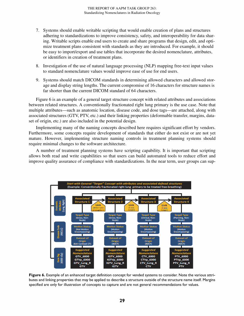
THE REPORT OF AAPM TASK GROUP 263:Standardizing Nomenclatures in Radiation Oncology
7. Systems should enable writable scripting that would enable creation of plans and structures adhering to standardizations to improve consistency, safety, and interoperability for data shar-ing. Writable scripts enable end users to create and share programs that design, edit, and opti-mize treatment plans consistent with standards as they are introduced. For example, it should be easy to import/export and use tables that incorporate the desired nomenclature, attributes, or identifiers in creation of treatment plans.
8. Investigation of the use of natural language processing (NLP) mapping free-text input values to standard nomenclature values would improve ease of use for end users.
9. Systems should match DICOM standards in determining allowed characters and allowed stor-age and display string lengths. The current compromise of 16 characters for structure names is far shorter than the current DICOM standard of 64 characters.
Figure 6 is an example of a general target structure concept with related attributes and associationsbetween related structures. A conventionally fractionated right lung primary is the use case. Note thatmultiple attributes—such as anatomic location, disease code, and dose tags—are attached, along withassociated structures (GTV, PTV, etc.) and their linking properties (deformable transfer, margins, data-set of origin, etc.) are also included in the potential design.
Implementing many of the naming concepts described here requires significant effort by vendors.Furthermore, some concepts require development of standards that either do not exist or are not yetmature. However, implementing structure naming controls in treatment planning systems shouldrequire minimal changes to the software architecture.
A number of treatment planning systems have scripting capability. It is important that scriptingallows both read and write capabilities so that users can build automated tools to reduce effort andimprove quality assurance of compliance with standardizations. In the near term, user groups can sup-
Figure 6. Example of an enhanced target definition concept for vended systems to consider. Note the various attri-butes and linking properties that may be applied to describe a structure outside of the structure name itself. Marginsspecified are only for illustration of concepts to capture and are not general recommendations for values.
29
THE REPORT OF AAPM TASK GROUP 263:Standardizing Nomenclatures in Radiation Oncology
port nomenclature standardization through development of validation scripts. These efforts will fur-ther support data integrity in clinical trials as described in AAPM Task Group 113.13
A standard format for communicating the set of structure names to be used for a clinical trial orclinical scenario is currently in development (DICOM Supplement 196). Broad implementation of thisspecification to create and distribute templates for structure identification in commercial image seg-mentation and treatment planning systems is expected to improve the consistency of structure namesand provide a means to distribute codes for structure identification and categorization. Manufacturersare encouraged to support implementation of this standard as it becomes available.
This group recommends that vendors place a priority on the development of systems that enableusers to enforce compliance with specific nomenclatures (e.g., TG-263 guidelines) and that the sys-tems allow the nomenclature rules to be configured by individual sites. The guidelines of TG-263 pro-mote goals for safety, clinical efficiency, clinical trials, and utilization of Big Data resource systemsthat are of common interest to users, vendors, and funding agencies to support advances in patientcare. The group recommends that vended systems be made to follow TG-263 guidelines within a two-year period.
12. Nomenclature Pilot Study Design and Results
12.1 Pilot Study Design
Change is hard. Implementing the new standards in the clinic requires addressing learning curves,implications for existing documentation, additional work for staff, process changes, etc. It is importantto know that new recommendations can be successfully implemented in clinical settings.
Before finalizing recommendations, the preliminary nomenclature was piloted by a group of fiveinstitutions for head and neck patients. The pilot study was used to identify any hindrances to imple-mentation, such as an overlooked anatomical site. Members also reported the ease or difficulty ofadopting nomenclature so improvements can be made before widespread adoption of the standards.Groups were asked to conform to the recommendations for non-target structures and explore willing-ness to adopt the guidelines for targets.
Several institutions that piloted the nomenclature also developed scripts and xml files to facilitateadoption of the nomenclature.
12.2 Pilot Study Results
Five groups—NRG (Philadelphia, PA), MD Anderson Cancer Center (Houston, TX), University ofFlorida (Jacksonville, FL), Karmanos Cancer Center (Detroit, MI), and the University of Michigan(Ann Arbor, MI)—participated in the pilot study. A sixth group, Princess Margaret Cancer Centre(Toronto, Ontario), piloted the nomenclature for breast patients. Several of the piloting institutions hadconducted internal reviews of naming variability in their current systems. The ability to converge on asingle system that eliminated the variability and improved data exchange with the NRG and otherinstitutions was generally found to be more compelling than local preferences for naming syntax.
Pilot groups reported little difficulty in implementing the nomenclature. For example, although thepilot was targeted for a subgroup of patients with head and neck cancer, several of the institutionsphased in adoption of the entire nomenclature for all disease sites. The nomenclature was readilyadopted into the NRG standards as new trials were added. A common approach for easing the transi-tion was the use of structure templates or scripting capabilities built into treatment planning systems toenable pre-populating the lists of structures seen by physicians and dosimetrists. In routine practice,when a planner wonders what name to choose for a structure, scripts that automate creation of plansand naming of structures could make using the standardized answer also the easy answer. Three
30
THE REPORT OF AAPM TASK GROUP 263:Standardizing Nomenclatures in Radiation Oncology
groups adopted the nomenclature in conjunction with upgrades to their radiation oncology informa-tion systems.
Some vendors incorporated the developing consensus nomenclature from the task group into theirproducts to facilitate the ability of users to standardize. Earlier versions of some vendor systems bor-rowed nomenclature from published and unpublished nomenclatures that had been previously devel-oped by members. Incorporations of TG standards into vended systems was very helpful forinstitutions piloting the nomenclature.
Some treatment planning systems include the ability to use templates and scripts to facilitate intro-duction of standardizations into clinical practice. Among our pilot sites, two were in use. Examples forthese systems are described below for practical illustration. This does not constitute an endorsement ofeither; there may or may not be better tools in other systems. Manufacturers are encouraged to supportadoption of the nomenclature by making it available in their systems for all users as systems are pur-chased or upgraded. They are further encouraged to make templates and scripts that facilitate imple-mentation of this nomenclature available when systems are purchased.
The use of nomenclature can be supported by different software versions in a way to support useradoption. For example, ARIA version 13.x provides a Structure Dictionary which includes Founda-tions of Medical Anatomy identification numbers (FMAIDs) if they exist. Users edited labels, defaultIDs, and synonyms for items most closely matching the nomenclature. Users can define specific treat-ment sites (e.g., breast, lung prostate, head and neck), structure templates, and treatment plan proto-cols that use the nomenclature. Each structure requires selection of a label from the StructureDictionary to identify the structure category. The Structure Dictionary can be updated by the vendor toinclude the recommended nomenclature. Templates and protocols can be exported as XML files andimported by other users to facilitate adoption of the nomenclature. To automate inspection of structurenames for alignment with the recommendations, some users created scripts that can run from Eclipseand highlight structures that are not following recommendations. The availability of writable scriptingthat would enable the creation of plans and structures adhering to the standard nomenclature was high-lighted in an important future advance.
A series of scripts were developed to aid structure naming in the Pinnacle Treatment PlanningSystem. The first script loads a graphical interface that allows user-specified names to auto-populatethe Pinnacle region of interest list. This interface shows the master list of TG-263 approved structurenames that can be used in Pinnacle. The user can select names from the master list or from a diseasesite-specific list containing a subset of the master name list. Target and non-standard structures can beadded using the TG-263 approved nomenclature.
Once the desired list of structure names is chosen, the names are saved to disk. A secondary Pin-nacle script loads the new list of names into the active Pinnacle session and populates the region ofinterest list. Duplicate names are not inserted.
In addition, each disease site has a script that can simply load all of the TG-263 approved structurenames that are deemed commonly used by a radiation oncologist for a given diagnosis. The final scriptremoves all structures from the Pinnacle region of interest list if no contouring was done. This featureprovides a quick way to remove unnecessary structures added by the site-specific bulk import.
Similar scripts can be developed for all commercially available treatment planning systems, thusencouraging the wide use of approved structure names in the community. Scripts and templates sim-plify the steps involved with adopting standard nomenclature and may help overcome some of the bar-riers to implementation. Staff should be trained using the tools, and leadership will need to affirm along-term commitment to the standardization effort. Additional training should focus on using the cor-rect nomenclature when the treatment site or organ is outside the department standards. It is noted thatthe pilot study participants were academically affiliated and may have less opposition to change thansmaller clinics with limited staffing. Smaller clinics may, therefore, encounter additional obstacles not
31
THE REPORT OF AAPM TASK GROUP 263:Standardizing Nomenclatures in Radiation Oncology
foreseen by this group. Hence, there is even greater importance placed on developing user-friendlyscripts which may greatly simplify the adoption of this nomenclature for such clinics.
The pilot study did not require participants to adopt the recommendations for target structures, butdid ask that they examine any barriers to adoption of the recommendations. The guidelines had beencarefully formulated in conjunction with NRG to facilitate adoption. Several clinics had already con-verged on the use of relative dose nomenclatures (e.g., PTV_High, PTV_Intermediate or PTV_Mid01,PTV_Low) as part of their routine practice. The relative dose nomenclatures made development ofstandardized templates possible without requiring conformance to particular dose prescriptions. It alsoenabled changing prescribed doses during treatment (e.g., move from 68 to 72 Gy) without requiring achange in the associated target structure names (e.g., PTV_High for both vs change from PTV_6800to PTV_7200). A few clinics had previously standardized the dose units in their planning system onGy vs cGy. As a result, the shift in dose representation in names (e.g., PTV_5040 vs PTV_50.4Gy)was considered a substantial change and safety concern without a properly educated rollout plan.Switching to relative dose levels (e.g., Low, Intermediate, and High) provided a means to bypass diffi-culties in changing.
13. Recommendations for ImplementationAt the time of publication, over 700 distinct structure names have been published separately on-line inthe complete list for this report. In practice, individual clinics only use a small fraction (e.g., 30) ofthese routinely. The task group recommends use of the standard values for the small subset of struc-tures relevant to their practice or participation in trials. Even a basic effort to change to standardizedstructure naming is beneficial for the individual clinic, as well as the radiation oncology community asa whole.
The task group recommendations facilitate the ability of clinics to best use their electronic recordsfor safety, productivity, research, and regulatory reporting. The importance of standardizations shouldbe emphasized in training programs for clinical staff.
A range of staff will be affected by clinical implementation of the nomenclature (e.g., physicians,dosimetrists, physicists, therapists, information technology, and administrative personnel). Gradualimplementation is encouraged to allow time to develop an understanding of the guidelines, specificstring values, and incorporation into their documentation.
A suggested work flow for implementation is listed below:
1. Identify common treatment sites (e.g., prostate, breast, head and neck) and corresponding staffing groups (e.g., physicians, dosimetrists, physicists, therapists) affected by changes in nomenclature.
2. Detail commonalities already in use for those treatment sites for target and non-target struc-ture naming and structure DVH metrics used in treatment plan evaluation.
3. Download the full list of non-target structure names recommended by this report.
4. Save the full list, and make a separate copy for editing.
5. In that Excel sheet, delete rows from the spreadsheet containing structures that are not needed by your clinic. (An example might be: delete all cranial nerve structures, delete all individual heart-vessel structures, etc.)
6. Discuss the final list, guidelines for target and non-target structures, and DVH metrics with the disease site groups and other stakeholders in your clinic as required by your organizational structure.
32
THE REPORT OF AAPM TASK GROUP 263:Standardizing Nomenclatures in Radiation Oncology
7. Identify local documentation templates used in the clinical practice that may need to be adjusted along with changes to the nomenclature (e.g., simulation and treatment directives, checklists used in plan review, etc.)
8. Develop a plan for gradual rollout of the nomenclature into clinical practice:
a. An example might be: implement non-target structure nomenclature and DVH metrics by disease site group over a defined period, and then implement clinic-wide target naming for all disease site groups.
b. Include all stakeholders in the discussion (e.g., physicians, dosimetry, therapists, physicists).
c. Consider where there are optimal break points in your clinical process for checking that correct values are used. Examples include plan review, plan check, and quality assurance rounds to review structures and doses.
d. It may be easier for clinics which are large enough such that practices are broken up by disease site, to implement non-target nomenclatures first on a site-by-site basis and then later implement target nomenclature clinic-wide.
9. Develop a short list and create templates in your treatment planning system containing your new standard structures:
a. One template that contains all of your standard structures.
b. Or, individual templates for each treatment type that contain only structures needed for that treatment type.
10. Retain the full list of structures as a reference for adding new structures to your templates as needed in the future.
14. Recommendations for Clinical Trial Study GroupsThe ability to automate, exchange, and combine data from multiple groups and studies is important forincreasing participation in trials, reducing cost (financial and staff time), and maximizing use ofaggregated data over time. The definition of a common nomenclature and guidelines for new struc-tures supports these objectives. Consistent usage of standardized nomenclature among trials is one ofthe best mechanisms for bringing this consistency to routine practice. We encourage clinical trialgroups to adopt these standardizations when defining new studies.
15. Recommendations for Working Group to Succeed Task GroupAs technologies and standards advance and data collection becomes more refined, further improve-ments to the proposed naming schemes may be required. TG-263 recommends that this group transi-tion into a working group which will continue to advance and extend the proposed scheme andmaintain an active list of the current nomenclature and guidelines. Standardization to improve com-munication, data sharing, and safety with focused needs for radiation oncology are important for awide range of data elements. These include treatment plan names, toxicities, treatment course names,prescription elements, patient-reported outcome items, survival, and recurrence status. Coordinationwith groups working as part of other organizations is needed to ensure emergence of standards thatcan be widely applied.
Another important hurdle to adopting one nomenclature in the worldwide RT community is thelack of one global native language. Although the many advantages of using only one language are
33
THE REPORT OF AAPM TASK GROUP 263:Standardizing Nomenclatures in Radiation Oncology
widely recognized, unfamiliarity with English or legal reasons may hamper the use of English in manycountries. Other obstacles may include character limits and differences in the interpretation of lateral-ity and other abbreviations. A working group could help establish guidelines for the translation ofnomenclature and support such activities as needed. Like the task group, the working group shouldinclude broad representation of stakeholders, including the DICOM work group and the InternationalAtomic Energy Agency (IAEA), which have experience in working across many languages. Theworking group might consider creating a translation table from the native language to the Englishnomenclature which may be (automatically) applied when data needs to be sent, stored, or mined in aninternational context.
The proposed working group could collaborate with the DICOM work group to construct a dictio-nary that treats the structure name as a unique ID and provides a meaningful, human-readable descrip-tion to the user. Using the DICOM standard requires (1) some institutions with recognized authority tocreate, distribute, and maintain a code scheme, and (2) RT manufacturers that support the use of codesin their segmentation and treatment planning software.
The dictionary could be coupled with an algorithm to derive a human-readable description. Suchan approach would allow for controlled growth of the dictionary system. Changes would affect fewerdictionaries, and would allow the ability to create or modify several related structures formed throughcombinations of the elements in other component dictionaries with the changed elements in theaffected dictionary. This allows for more efficient maintenance of the system of component dictionar-ies. The alternative approach to a single dictionary would involve entering one line of information forall affected combinations of components that are used to build the unique identifiers and the compileddictionary.
The working group could start maintaining and extending the proposed scheme using theapproach of efforts such as FMA, Radlex (Radiology naming scheme), and ICD. These efforts publishtheir scheme regularly at the aforementioned Bioportal (http://bioportal.bioontology.org/) as a formalontology and between releases collect community feedback and suggested improvements via toolssuch as WebProtege (http://protege.stanford.edu/). This could augment and incorporate existing effortto develop radiation oncology specific ontologies such as the Dependency Layered Ontology for Radi-ation Oncology (http://bioportal.bioontology.org/ontologies/DLORO) and the Radiation OncologyOntology (http://bioportal.bioontology.org/ontologies/ROO).
This effort is not addressing terms used to define clinical outcomes (e.g., toxicity, local control,survival). The need for establishment and promulgation of a standard nomenclature for structures andDVH metrics with sponsorship by a professional society, such as AAPM, is immediate for manyresearch efforts and for vendor progress on implementation in their systems. Standardization of termsused to define clinical outcomes is important, but not as immediate. These clinical outcome termsshould be taken up by the succeeding working group.
16. Summary of Key Take-Home Points
• Standardized nomenclatures add value to radiation oncology by providing a basis for improved communication and the ability to develop automated solutions for data extraction and quality assurance to improve clinical work flows, safety, and research.
• The nomenclature was developed through the combined effort of many clinics, vendors, and clinical trial groups (e.g., NRG, RTOG) to define a viable consensus recommendation. The nomenclature has already been put into routine use in many clinics as part of clinical trials and in vendor software, demonstrating that it is a viable solution.
34
THE REPORT OF AAPM TASK GROUP 263:Standardizing Nomenclatures in Radiation Oncology
• The nomenclature was defined to work within the storage and display limits of a range of vended systems to convey information on structure types and laterality.
• Guidelines for target structure naming were created to allow a range of information to be con-veyed using a standardized syntax allowing automated parsing of the information from the name.
◦ When dose is used as a part of target naming, relative dose levels are recommended (e.g., PTV_High, PTV_Low). If physical dose is required, then units of cGy are preferred, aligning with current recommendations of the ASTRO group defining guidelines for prescriptions and RO-ILS.
• Guidelines for non-target structures and specific values defined for over 700 structures were created, including identification codes for corresponding Foundational Model of Anatomy structures.
• A DVH nomenclature detailing input and output units for high-dose and low-dose metrics and radiobiological metrics was recommended that was designed to use regular expressions to auto-mate parsing parameters needed for automated calculations.
• Non-segmented target structures were recommended for the default standard for contouring. However, target structure nomenclature guidelines define a means to identify segmented struc-tures when they are preferred.
• The nomenclature was piloted in clinic, vendor, and trials groups to prove viability of the recom-mendations prior to release.
• Vendor participation was important in nomenclature development and is beneficial to facilitate implementation in those vended systems.
17. AcknowledgmentsAll members of the task group were vital to our ability to identify and vet a practical approach viablefor a wide and diverse set of stakeholders. Each person has contributed to our result, and we are grate-ful to each one. It is not possible in an effort of this size to properly acknowledge the contributions ofall members in the ordering of the author list. There are a few people whom we would like to thankexplicitly for particular contributions that they carried out beyond the view of most of our members.Susan Richardson provided a spreadsheet from her experience with implementing nomenclatures thatformed an important base for the structure nomenclature list that emerged. Peter Gabriel clarified thedetails of SNOMED CT and FMA improving our understanding of existing ontologies. ElizabethCovington led a subgroup including Tim Ritter, Tomasz Morgas, and Kathryn Masi that poured overthe structure nomenclature list relentlessly, cleaning up typos, removing inconsistencies, and checkingFMAIDs. Colleen Fox and Tim Ritter worked tirelessly through the many revisions of the documentto collate reviewer comments. We are grateful for the many AAPM, ASTRO, and ESTRO memberswho have encouraged this work and seen its value to the larger efforts of the radiation oncology com-munity. In particular, we thank Benedick Fraass and Emily Wilson for their support with these profes-sional organizations and Andre Dekker and Coen Hurkmans for their support in the internationalcommunity and with ESTRO. We would like to thank the many reviewers from AAPM Science Coun-cil, AAPM Professional Council, AAPM Therapy Physics Committee, AAPM Quality Assurance andOutcome Improvement Subcommittee, AAPM Working Group on Clinical Trials, ASTRO, ESTRO,and AAMD whose contributions have positively impacted the clarity and depth of the recommenda-tions. We gratefully acknowledge the vision and leadership of Benedick Fraass in coordinating and
35
THE REPORT OF AAPM TASK GROUP 263:Standardizing Nomenclatures in Radiation Oncology
coalescing reviews by ASTRO, ESTRO, and AAMD. Special thanks are extended to Walter Boschand Ying Xiao for the many hours spent working through detailed examinations of the guidelines andstructure lists to test, at many stages, implications of the TG’s deliberations on the work of theDICOM working group and NRG. Finally, we thank Robin Stern, Andrea Molineu, Jean Moran, andSaiful Huq for their vision and long hours of support and effort.
18. References 1. J. Yu, W. Straube, C. Mayo, T. Giaddui, W. Bosch, K. Ulin, S. F. Kry, J. Galvin, and Y. Xiao.
(2014). “Radiation therapy digital data submission process for national clinical trials network.” Int J Radiat Oncol Biol Phys 90:466–467.
2. L. Santanam, C. Hurkmans, S. Mutic, C. van Vliet-Vroegindeweij, S. Brame, W. Straube, J. Galvin, P. Tripuraneni, J. Michalski, and W. Bosch. (2012). “Standardizing naming conven-tions in radiation oncology.” Int J Radiat Oncol Biol Phys 83:1344–49.
3. C. S. Mayo, T. M. Pisansky, I. A. Petersen, E. S. Yan, B. J. Davis, S. L. Stafford, Y. I. Garces, R. C. Miller, J. A. Martenson, R. W. Mutter, R. Choo, C. L. Hallemeier, N. N. Laack, S. S. Park, D. J. Ma, K. R. Olivier, S. R. Keole, M. Fatyga, R. L. Foote, and M. G. Haddock. (2016). “Estab-lishment of practice standards in nomenclature and prescription to enable construction of software and databases for knowledge-based practice review.” PRO 6(4):e117–26.
4. J. Kim, S. Breen, J. Waldron, A. Bayley, B. Cummings, J. Ringash, L. Dawson, C. Liu, S. Huang, and B. O’Sullivan. (2007). “A standardized nomenclature system for head and neck( H&N) IMRT contouring, planning and quality assurance.” Int J Radiat Oncol Biol Phys 69(3):S473.
5. V. Gregoire, K. Ang, W. Budach, C. Grau, M. Hamoir, J. A. Langendijk, A. Lee, Q. T. Le, P. Maingon, C. Nutting, B. O’Sullivan, S. V. Porceddu, and B. Lengele. (2014). “Delineation of the neck node levels for head and neck tumors: a 2013 update. DAHANCA, EORTC, HKN-PCSG, NCIC CTG, NCRI, RTOG, TROG consensus guidelines.” Radiother Oncol 110:172–81.
6. A. Jackson, L. B. Marks, S. M. Bentzen, A. Eisbruch, E. D. Yorke, R. K. Ten Haken, L. S. Cons-tine, and J. O. Deasy. (2010). “The lessons of QUANTEC: recommendations for reporting and gathering data on dose-volume dependencies of treatment outcome.” Int J Radiat Oncol Biol Phys 76(3 Suppl):S155–60.
7. J. O. Deasy, S. M. Bentzen, A. Jackson, R. K. Ten Haken, E. D. Yorke, L. S. Constine, A. Sharma, and L. B. Marks. (2010). “Improving normal tissue complication probability models: the need to adopt a ‘data-pooling’ culture.” Int J Radiat Oncol Biol Phys 76(3 Suppl):S151–54.
8. J. Purdy. (2008). “Quality assurance issues in conducting multi-institutional advanced technology clinical trials.” Int J Radiat Oncol Biol Phys 71:S66–70.
9. H. Bauchner, R. M. Golub, P. B. Fontanarosa. (2016). “Data sharing: An ethical and scientific imperative.” JAMA 315(12):1237–39.
10. J. S. Ross, R. Lehman, and C. P. Gross. (2012). “The importance of clinical trial data sharing: toward more open science.” Circ Cardiovasc Qual Outcomes 5(2):238–40.
11. D. B. Taichman, P. Sahni, A. Pinborg, L. Peiper, C. Laine, A. James, S. T. Hong, A. Haileamlak, L. Gollogly, F. Godlee, F. A. Frizelle, F. Florenzano, J. M. Drazen, H. Bauchner, C. Baethge, and J. Backus. (2017). “Data sharing statements for clinical trials—a requirement of The Interna-tional Committee of Medical Journal Editors. NEJM 376:2277–79.
12. J. F. Williamson, S. K. Das, M. S. Goodsitt, and J. O. Deasy. (2017). “Introducing the medical physics data set article.” Med Phys 44(2):349–51.
13. J. M. Moran, A. Molineu, J. J. Kruse, M. M. Urie, M. Oldham, R. E. Drzymala, R. Jeraj, J. M. Galvin, J. R. Palta, J. A. Purdy, and A. J. Olch. “AAPM Report Task Group 113: improving physics practices for external beam radiation therapy clinical trials.” Alexandria, VA: American
36
THE REPORT OF AAPM TASK GROUP 263:Standardizing Nomenclatures in Radiation Oncology
Association of Physicists in Medicine, 2018. https://www.aapm.org/pubs/reports/detail.asp?docid=172.
14. E. E. Furhang, J. Dolan, J. K. Sillanpaa, and L. B. Harrison. (2009). “Automating the initial phys-ics chart checking process.” J Appl Clin Med Phys 10:2855.
15. B. Wu, F. Ricchetti, G. Sanguineti, M. Kazhdan, P. Simari, M. Chuang, R. Taylor, R. Jacques, and T. McNutt. (2009). “Patient geometry-driven information retrieval for IMRT treatment plan qual-ity control.” Med Phys 36:5497–505.
16. K. L. Moore, R. S. Brame, D. A. Low, and S. Mutic. (2011). “Experience-based quality control of clinical intensity-modulated radiotherapy planning.” Int J Radiat Oncol Biol Phys 81:545–51.
17. National Patient Safety Agency. “Quarterly Data Summary Issue 8.” (1 Jan 2007 to 31 Mar 2008). http://www.nrls.npsa.nhs.uk/resources/type/data-reports/?entryid45=59842&p=3.
18. J. Cunningham, M. Coffey, T. Knoos, and O. Holmberg. (2010). “Radiation Oncology Safety Information System (ROSIS)—profiles of participants and the first 1074 incident reports.” Radiother Oncol 97:601–07.
19. American Society for Radiation Oncology (ASTRO). “2017 RO-ILS Year in Review.” https://www.astro.org/uploadedFiles/_MAIN_SITE/Patient_Care/Patient_Safety/RO-ILS/2017YIR.pdf.
20. S. B. Evans, B.A. Fraass, P. Lerner, K. S. Collins, T. Nurushev, M. J. O’Neill, J. Zheng, and L. B. Marks. (2016). “Standardizing dose prescriptions: an ASTRO white paper.” Pract Radiat Oncol 6:e369–81.
21. University of Washington. “Foundational Model of the Anatomy” (home page of Foundational Model of the Anatomy). http://si.washington.edu/projects/fma. Accessed January 9, 2018.
22. E. L. Covington, X. Chen, K. C. Younge, C. Lee, M. M. Matuszak, M. L. Kessler, W. Keranen, E. Acosta, A. M. Dougherty, S. E. Filpansick, and J. M. Moran. (2016). “Improving treatment plan evaluation with automation.” J Appl Clin Med Phys 17(6):6322.
23. C. S. Mayo, J. Yao, A. Eisbruch, J. M. Balter, D. W. Litzenberg, M. M. Matuszak, M. L. Kessler, G. Weyburn, C. J. Anderson, D. Owen, W. C. Jackson, and R. Ten Haken. (2017). “Incorporating big data into treatment plan evaluation: Development of statistical DVH metrics and visualization dashboards.” Adv Radiat Oncol 27(3):503–14.
37