tgn op anleitung engl - stryker - tgn - optech - 060603 ver4.pdf · the gamma ® locking nail ......
TRANSCRIPT

1
HIP FRACTURE SYSTEMS
OPERATIVE TECHNIQUE

T R O C H A N T E R I C G A M M A ® L O C K I N G N A I L

C O N T E N T S
Acknowledgements:
The Gamma® Locking Nail Operating Technique was compiled from thekind contributions of leading surgeons in many countries; the principalauthors and commentators were:-
Dr. G. Taglang, Dr. A. Grosse, Strasbourg, FranceDr. S.C. Halder, Halifax, UK Dr K.S. Leung, Hong Kong Dr. S. Boriani, Bologna, Italy
Our thanks are due to the many surgeons whose work has helped to confirmthe utility of the technique to present and future users of the Gamma® LockingNail family.
Warning:
Bone screws referenced in this material are not approved for screwattachment or fixation to the posterior elements (pedicles) of the cervical,thoracic or lumbar spine.
THE TROCHANTERIC GAMMA® LOCKING NAIL 4
INDICATIONS AND DESIGN FEATURES 6
COMPLETE OPERATING GUIDE 8
Pre-operative Planning 9
Patient Positioning, Fracture Reduction 10
Anteversion Guide 11
Incision & Entry Point 12
Preparation of Medullary Cavity 13
Reaming Technique 13
Nail Insertion 14
Nail/Lag Screw Positioning 14
Lag Screw Targeting 15
Lag Screw Drilling 17
Lag Screw Selection and Insertion 18
Set Screw Insertion 19
Distal Locking 20
Final Checking 22
Extraction 23
Problem Solving 24
Implants and Instrumentation 29
Instrument Guide 32
3
This publication sets forth detailed recommended procedures for usingStryker Trauma devices and instruments. It offers guidance that you shouldheed, but, as with any such technical guide, each surgeon must consider theparticular needs of each patient and make appropriate adjustments whenand as required.

The Trochanteric Gamma® Locking Nail is the latest
development in the continuing evolution of the Gamma®
Locking Nail family. Like the original Gamma® and Long
Gamma® Locking Nails, the Trochanteric Gamma® Locking
Nail has been designed by surgeons. The requirement,
based on the Gamma® experience of over three hundred
thousand implants world-wide, was to develop an implant
specifically for fractures in the trochanteric region, but with
all the benefits of the existing Gamma® Locking Nail family.
The new Trochanteric Gamma® Locking Nail is shorter
and simpler than the standard Gamma® Locking Nail, and
has:-
● only one distal locking screw
● only one distal diameter
● 180 mm overall length
● profile designed for rapid and secure fixation of
fractures around the trochanter
The Trochanteric Gamma® Locking Nail uses the same
award-winning instrumentation* as the standard and Long
Gamma® Locking Nails, with the addition of new targeting
sleeves. It combines the strength and biomechanical
advantages of the existing Gamma® family with a small
inventory and simplified technique. And, as the latest
development of one of the world’s leading locking nails, the
design of the Trochanteric Gamma® Locking Nail benefits
from an unrivalled pedigree of clinical experience.
* Design-Innovation ’95, awarded for high design quality; Design Centre, Nordrhein Westfalen.
Published clinical studies for the Gamma® Locking Nail
family are among the most extensive for any surgical
implant currently available. They consistently illustrate how
successfully this evolving range of implants has achieved the
original design goals: to improve both the procedure and
prognosis for all grades of femoral fracture by extending the
application of the established intramedullary principle to set
a new standard for treatment:
● Early weight-bearing1,2,3,4,5,6,7 through superior
strength and stability
● Reduced trauma3,4 through closed operating
technique3,4
● Low blood loss5,6, low level of wound problems5
and low risk of infection5
● More secure fracture fixation through better
biomechanics7
The clinical objective of the Trochanteric Gamma®
Locking Nail, as with the original and Long Gamma®
Locking Nails, is:-
Rapid mobilization, with fewer complications, for
better patient rehabilitation7
The operating technique for the Trochanteric Gamma®
Locking Nail is essentially the same as for the standard
Gamma® Locking Nail, the main variation being in the
simpler distal locking process. Instrumentation for the
Trochanteric Gamma Nail is also the same as for the rest of
the Gamma® family, obviating the need for further inventory
and training for both the surgeon and the theatre team.
The aim of this surgical technique booklet is to provide
you with a simple step-by-step operating guide to aid
successful adoption of the Trochanteric Gamma® Locking
Nail into your standard trauma practice.
Once the technique has been learned, you should find
the operative procedures simple to implement. In fact, many
of the basic principles for the Trochanteric Gamma®
technique are those employed for all intramedullary closed
locking nailing.
If you are in any doubt as to any part of the operating
procedure, please contact your local Stryker Trauma
representative or the office shown on the back cover.
T H E T R O C H A N T E R I C G A M M A ® L O C K I N G N A I L
4
REFERENCES: 1. Grosse A., Favreul E., Taglang G., “The Gamma® Nail; The results at theCTO Strasbourg” Paper presented at the International Symposium “RecentAdvances in Locking Nails”, Hong Kong, 1992.2. Taglang G., Favreul E., “Results from the Centre de Traumatologie etd’Orthopédie, Strasbourg”: Paper presented at the Advanced Course inIntramedullary Locking Nailing, Courchevel, France, February 1991.3. Leung K.S. et al, (Prince of Wales Hospital, Hong Kong), J Bone JointSurg [Br] 1992; 74B, 3:345-51. 4. Boriani S. et al., results of Multicentric Italian Experience on the Gamma®
Nail. A report on 648 cases, Orthopedics 1991;14,12: 1307-1314. 5. Radford P.J.,(University Hospital Queen’s Medical Centre, Nottingham,England):”Comparison of results of the Gamma® Nail and Dynamic HipScrew in Extracapsular fractures of the Proximal Femur.”: Paper presented atAdvanced Course in Intramedullary Locking Nailing, Courchevel, France,February 1991.6. Williams J.J., Cohen P.Z., Pittsburgh Orthopaedic Journal, 1990,Volume 1, pages 20 - 23.7. De Groote W., Van Hoye M. et al, (St Jan General Hospital,Bruge/Middelheim General Hospital, Antwerp, Belgium): “The Gamma®
Locking Nail in the treatment of trochanteric fractures” Article in press.
5

Indications
Intertrochanteric fractures
Pertrochanteric fractures
High sub-trochanteric fractures
Anatomical efficiency
The Trochanteric Gamma® Locking Nail is designed for
optimum efficiency both in operating technique and
subsequent rehabilitation.
There are two basic components, universal in
application to left or right hip fractures, and effective
together in a very wide range of clinical situations and
fracture complexity.
Insertion is entirely by closed surgical technique,
minimizing trauma, blood loss and infection potential.
The Nail
The intramedullary nail itself integrates several important
mechanical features. The anatomic design is universal for all
indicated applications, with a profile specifically designed
for trochanteric fractures, and is 18 centimetres long overall.
Variations in femoral neck anatomy are accommodated
by a range of angles available for the lag screw entry
(125°, 130°, 135°).
A single distal locking screw is used to prevent rotation
in complex fractures. Cannulated for guide wire controlled
insertion, and with a conical tip, the nail is available in a
single distal diameter, 11 mm.
The Lag Screw
The lag screw, inserted through a small incision with the
aid of a radiolucent targeting device, incorporates a
special sliding lock to provide dynamic compression with
axial stability.
After insertion, a set screw inserted through the proximal
head of the nail engages in one of four grooves in the lag
screw. As these are of asymmetrical depth profile, they
allow the lag screw to slide in one direction, producing
dynamic osteosynthesis by compression during early weight-
bearing.
The lag screw incorporates a rounded nose profile and
self-tapping thread designed for easy insertion and
resistance to cut-out.
I N D I C A T I O N S A N D D E S I G N F E A T U R E S
6

The Gamma® advantage –
strength and stability
The Trochanteric Gamma® Locking Nail offers significantly
greater strength and stability in clinical use through the
inherent biomechanical advantage of the intramedullary
system.
The biomechanical advantage
As the load-bearing axis of the Trochanteric Gamma®
Locking Nail is closer to the hip joint fulcrum, the effective
lever on the implant and femur is significantly less than with
an external plate, reduced by a factor equivalent to d/D in
the diagram (approximately 25%*).
The resultant force is transmitted directly down the centre
of the femur rather than through the many bone-weakening
screws used in the side-plate system, increasing both the
strength and reliability of the mechanical repair.
The rehabilitation advantage
The extra strength effectively gained by the biomechanical
advantage of the Trochanteric Gamma® Locking Nail,
combined with improved control of axial telescoping and
rotational instability, allows early weight-bearing even in
complex or unstable proximal fractures.
Earlier mobilization, combined with dynamic
compression and less traumatic operative technique,
increases the chance of successful patient recovery and
reliable repair.
* Leung K.S., The Chinese University of Hong Kong: Gamma® AP Anthropometric Study of Proximal Femur, Jan 1991; Data on file, Stryker Trauma.
7
Proximal plug
Lag Screw
Nail
Set screw
Distal lockingscrew
Distal diameter 11 mm
Proximal diameter 17 mm
Length180 mm
Angles:125°, 130°& 135°
D > d
dD
IND
ICA
TION
S &
DESIG
N FEA
TUR
ES

This surgical technique has been devised in consultation
with leading surgeons in many countries to be a basic
guide, particularly for less experienced users of the
Trochanteric Gamma® Locking Nail.
It is acknowledged that several alternative approaches
to certain elements of the procedure are practised, and may
have advantages for particular situations or surgeons. Parts
of this guide may seem simplistic or redundant for
experienced readers, but are included for the guidance of
more junior staff.
A chart of the complete operating instrumentation is
folded into the back of this Operating Guide, and can be
folded out for easy reference in conjunction with the text that
follows. For easy identification, each instrument referred to
in the guide is keyed to the chart by a reference number,
and contains pictures of the Instrumentation and Implant
cases, shown on page 30 and 31 complete with the
catalogue numbers of each item.
C O M P L E T E O P E R A T I N G G U I D E
8

In the majority of patients the standard 130° neck angle
can be used without difficulty. The 125° neck angle may be
needed in osteoarthritic coxa vara, and the 135° in coxa
valga. Where such variations in femoral anatomy require
an alternative, the following method may be used to confirm
the nail angle selection:-
Implant Selection
X-ray templates are very helpful during preoperative
planning. Use the X-ray Templates for short and long nails
to select the correct implant and the optimal implant size.
These templates show the true implant size at a
magnification of 15%. The X-rays should be taken at this
magnification (15%) for an optimum surgical outcome.
If accurate anatomical reduction has been achieved,
the X-ray can be taken from the fractured hip or from the
contralateral side.
NOTE: Please ensure precise alignment of the
affected hip joint when using these templates.
Template magnification is 15%. All dimensions
(target angle and implant sizing) resulting
from using these templates must be verified
intraoperatively to ensure proper implant selection.
P R E - O P E R A T I V E P L A N N I N G
9
CO
MP
LETE OP
ERA
TING
GU
IDE
Cat. No. 1204-1000

Image intensifier positioning
The image intensifier is positioned so that anterior-posterior
and medio-lateral views of the trochanteric region of the
affected femur can be easily obtained. This position is best
achieved if the image intensifier can be positioned so that
the axis of rotation of the intensifier is centred on the
femoral neck of the affected femur.
It is important to ensure that a view of both the distal
and proximal tips of the nail can be obtained during the
procedure without obstruction by the traction table.
Fracture reduction
The patient is placed in a supine position on the fracture
table and closed reduction of the fracture is obtained as
shown in figure 1.
Traction is applied to the fracture, keeping the leg
straight.
Maintaining the traction, the leg is internally rotated 10-
15 degrees to complete the reduction of the fracture; the
patella should then be either horizontal or slightly internally
rotated.
IMPORTANT
Reduction should be achieved as anatomically as
possible. If this is not achievable, reduction in one
plane should be achieved, leaving reduction in the
other plane to be achieved with the Trochanteric
Gamma® Locking Nail during insertion.
The unaffected leg is abducted as far as possible in order
to accommodate the image intensifier.
The patient is then prepared and draped as for
standard hip fracture fixation, but bear in mind that the
incision is rather more proximal when positioning the
drapes.
P A T I E N T P O S I T I O N I N G & F R A C T U R E R E D U C T I O N
10
Figure 1
Figure 2

Anteversion guide insertion
With the image intensifier C-arm in the horizontal position to
give the lateral view of the femoral neck and head, a 2 mm
Kirschner wire is inserted percutaneously, anterior to the
shaft and parallel to the axis of the femoral neck and head.
This is to provide a guide to the angle of anteversion of the
femoral neck during later insertion of the nail, during which
the targeting device is kept parallel to the Kirschner wire in
the coronal plane (Figure 3).
Alternatively, the guide wire can be inserted after the
lag screw guide sleeve is placed in position (see page 15).
11
Figure 3

INCISION
Determination of the soft tissue
incision position
With experience, the tip of the greater trochanter can be
located by palpation, and a horizontal skin incision of
approximately 5 cm is made from the greater trochanter to
the iliac crest. The incision is deepened through the fascia
lata, splitting the abductor muscle for approximately 3 cm
immediately above the tip of the greater trochanter, thus
exposing its tip. A self-retractor is put in place (Figure 4).
ENTRY POINT
Finding the bone entry point
The correct entry point can be identified by touch; it is
located at the junction of the anterior third and posterior
two-thirds of the tip of the greater trochanter and on
the tip itself.
Breaching the cortex
The medullary canal is opened, under image intensification
if necessary; use of the two-part curved awl (1) from the
special instrument tray is recommended, as its conical
sleeve is designed to be left in place to facilitate passage
of the reamer guide wire. Care must be taken to ensure that
the awl is not misplaced; this is more likely in the anterior-
posterior plane i.e. as seen on the lateral view.
The insertion point should be just on the tip of the
greater trochanter. If it is very medial (e.g. in the piriform
fossa) the nail will not go down the shaft properly, with the
danger of fracturing the femur.
When the entry point has been made, the reamer guide
wire is placed in position so that the proximal femur may be
prepared using flexible intramedullary reamers (Figure 5).
I N C I S I O N & E N T R Y P O I N T
12
Figure 4
Figure 5
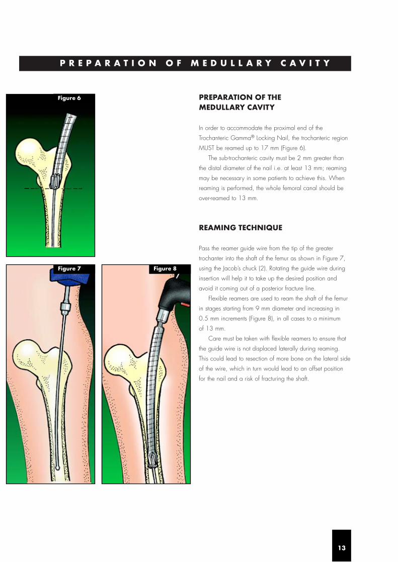
PREPARATION OF THE MEDULLARY CAVITY
In order to accommodate the proximal end of the
Trochanteric Gamma® Locking Nail, the trochanteric region
MUST be reamed up to 17 mm (Figure 6).
The sub-trochanteric cavity must be 2 mm greater than
the distal diameter of the nail i.e. at least 13 mm; reaming
may be necessary in some patients to achieve this. When
reaming is performed, the whole femoral canal should be
over-reamed to 13 mm.
REAMING TECHNIQUE
Pass the reamer guide wire from the tip of the greater
trochanter into the shaft of the femur as shown in Figure 7,
using the Jacob’s chuck (2). Rotating the guide wire during
insertion will help it to take up the desired position and
avoid it coming out of a posterior fracture line.
Flexible reamers are used to ream the shaft of the femur
in stages starting from 9 mm diameter and increasing in
0.5 mm increments (Figure 8), in all cases to a minimum
of 13 mm.
Care must be taken with flexible reamers to ensure that
the guide wire is not displaced laterally during reaming.
This could lead to resection of more bone on the lateral side
of the wire, which in turn would lead to an offset position
for the nail and a risk of fracturing the shaft.
P R E P A R A T I O N O F M E D U L L A R Y C A V I T Y
13
Figure 7 Figure 8
Figure 6
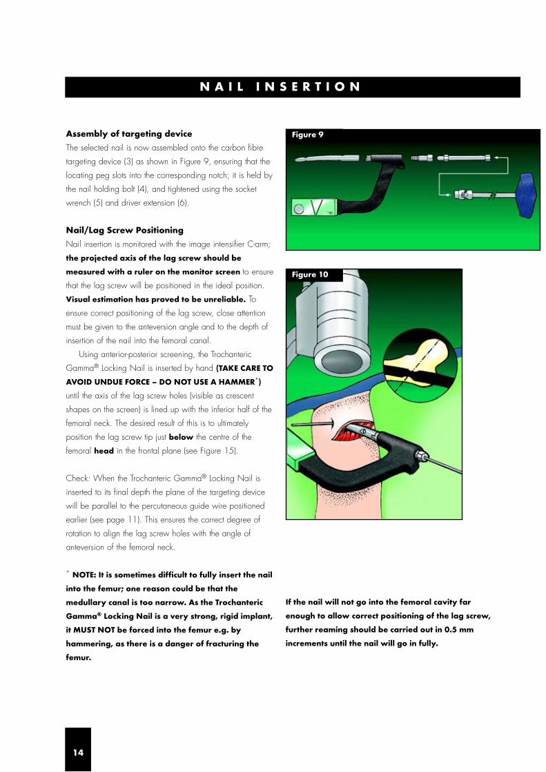
Figure 9
N A I L I N S E R T I O N
14
Assembly of targeting device
The selected nail is now assembled onto the carbon fibre
targeting device (3) as shown in Figure 9, ensuring that the
locating peg slots into the corresponding notch; it is held by
the nail holding bolt (4), and tightened using the socket
wrench (5) and driver extension (6).
Nail/Lag Screw Positioning
Nail insertion is monitored with the image intensifier C-arm;
the projected axis of the lag screw should be
measured with a ruler on the monitor screen to ensure
that the lag screw will be positioned in the ideal position.
Visual estimation has proved to be unreliable. To
ensure correct positioning of the lag screw, close attention
must be given to the anteversion angle and to the depth of
insertion of the nail into the femoral canal.
Using anterior-posterior screening, the Trochanteric
Gamma® Locking Nail is inserted by hand (TAKE CARE TO
AVOID UNDUE FORCE – DO NOT USE A HAMMER*)
until the axis of the lag screw holes (visible as crescent
shapes on the screen) is lined up with the inferior half of the
femoral neck. The desired result of this is to ultimately
position the lag screw tip just below the centre of the
femoral head in the frontal plane (see Figure 15).
Check: When the Trochanteric Gamma® Locking Nail is
inserted to its final depth the plane of the targeting device
will be parallel to the percutaneous guide wire positioned
earlier (see page 11). This ensures the correct degree of
rotation to align the lag screw holes with the angle of
anteversion of the femoral neck.
* NOTE: It is sometimes difficult to fully insert the nail
into the femur; one reason could be that the
medullary canal is too narrow. As the Trochanteric
Gamma® Locking Nail is a very strong, rigid implant,
it MUST NOT be forced into the femur e.g. by
hammering, as there is a danger of fracturing the
femur.
If the nail will not go into the femoral cavity far
enough to allow correct positioning of the lag screw,
further reaming should be carried out in 0.5 mm
increments until the nail will go in fully.
Figure 10

Remove the reaming guide wire using the Jacob’s chuck (2),
ensuring that the targeting device is supported to prevent
rotational movement of the Trochanteric Gamma® Nail.
With the nail now inserted to the correct depth, slide the
Trochanteric Gamma® targeting sleeve (colour-coded green)
(7) corresponding to the nail angle of the selected
Trochanteric Gamma® Locking Nail onto the end of the
carbon fibre targeting device (3) (Figure 11). ENSURE
YOU ARE USING THE TROCHANTERIC SLEEVE (GREEN
CODED), NOT THE STANDARD OR LONG GAMMA®
TARGETING SLEEVES.
Please ensure before proceeding that the nail
holding bolt (4) is fully tightened.
The targeting device (3) may require support by an
assistant, to prevent its weight from externally rotating the
nail, until the next stage is completed.
Next, assemble the soft tissue protector (8) and the
guide sleeve for the lag screw (9), and pass them through
the targeting sleeve (7) to the level of the skin. This now
indicates the position for the small incision to be made,
which is developed down to the bone.
The guide sleeve and tissue protector assembly is now
passed through the incision to press firmly against the lateral
cortex (Figure 12). If the guide catches the fascia lata,
twisting it will usually allow it to pass through to the bone.
If not already inserted, the percutaneous
anteversion guide should now be placed (see
page 11).
The soft tissue protector (8) is removed and the lag
screw guide sleeve (9) is firmly abutted to the lateral cortex
of the femur to stabilize the targeting device (Figure 13).
The thumbwheel on the targeting sleeve (7) should be
tightened to lock the guide sleeve (9) in place and further
stabilize the targeting assembly (Figure 13 inset).
L A G S C R E W T A R G E T I N G
15
Figure 11
Figure 13Figure 12
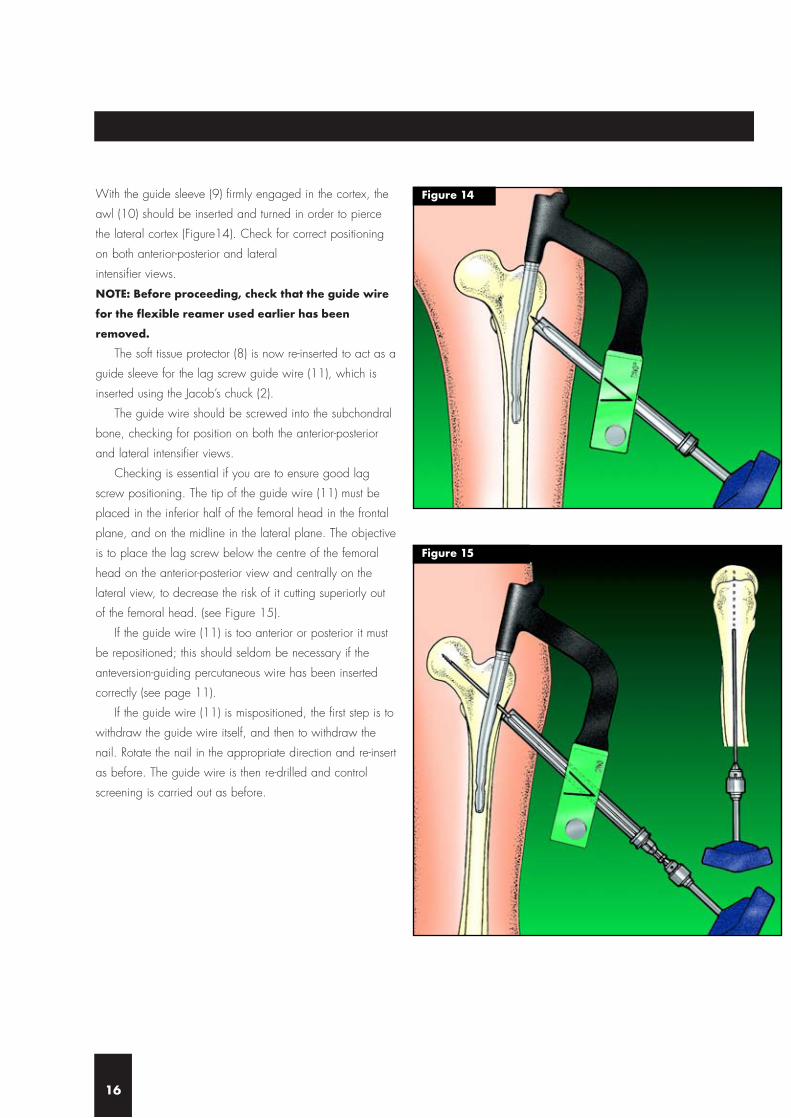
With the guide sleeve (9) firmly engaged in the cortex, the
awl (10) should be inserted and turned in order to pierce
the lateral cortex (Figure14). Check for correct positioning
on both anterior-posterior and lateral
intensifier views.
NOTE: Before proceeding, check that the guide wire
for the flexible reamer used earlier has been
removed.
The soft tissue protector (8) is now re-inserted to act as a
guide sleeve for the lag screw guide wire (11), which is
inserted using the Jacob’s chuck (2).
The guide wire should be screwed into the subchondral
bone, checking for position on both the anterior-posterior
and lateral intensifier views.
Checking is essential if you are to ensure good lag
screw positioning. The tip of the guide wire (11) must be
placed in the inferior half of the femoral head in the frontal
plane, and on the midline in the lateral plane. The objective
is to place the lag screw below the centre of the femoral
head on the anterior-posterior view and centrally on the
lateral view, to decrease the risk of it cutting superiorly out
of the femoral head. (see Figure 15).
If the guide wire (11) is too anterior or posterior it must
be repositioned; this should seldom be necessary if the
anteversion-guiding percutaneous wire has been inserted
correctly (see page 11).
If the guide wire (11) is mispositioned, the first step is to
withdraw the guide wire itself, and then to withdraw the
nail. Rotate the nail in the appropriate direction and re-insert
as before. The guide wire is then re-drilled and control
screening is carried out as before.
16
Figure 14
Figure 15

After achieving a satisfactory position for the guide wire
(11), the lag screw length required is measured using the
lag screw length measuring gauge (12). Before starting to
measure, ensure that the guide sleeve (9) is pressed firmly
against the lateral cortex of the femur.
Take the measuring gauge (12) and place it directly
under the guide wire (11) as shown in Figures 16a & b.
The measurement on the gauge is now transferred to the
adjustable stop on the lag screw step drill (13). It should be
noted that the adjustable stop is positioned with the chosen
length next to the stop on the side towards the
drill tip (Figure 17a). The collar is used to lock the stop in
position (Figure 17b).
L A G S C R E W D R I L L I N G
17
Figure 16a
Figure 17a
Figure 17b
Figure 16b

The soft tissue protector (8) is now removed and the lag
screw step drill (13) is passed over the guide wire (11),
through the guide sleeve (9) (see Figure 18a). The path for
the lag screw is drilled using the Jacob’s chuck (2). If
exceptional resistance is encountered, a power drill may be
used with great care. Drilling should continue until the stop
impacts against the guide sleeve (see Figure 18b),
ensuring that the targeting device is well supported
to prevent backing out and rotation.
If you check on the image intensifier at this stage you
should see the tip of the guide wire protruding slightly from
the step drill (Figure 18c). This is because the threaded
portion of the guide wire is deliberately excluded from the
drill measurement to prevent joint penetration by the drill.
The correct length lag screw is chosen by selecting a
size at least 5 mm longer than the measurement previously
made on the lag screw gauge (12) for drilling (see Figure
16). It is important that the lag screw protrudes at least
5 mm from the lateral femoral cortex to retain rotational
stability and to permit sliding.
The correct size lag screw is now assembled with the
lag screwdriver (14). The end thumbwheel must be pulled
back, and the screw and driver connected as shown
(Figure 19).
After pulling back and connecting, the end thumbwheel
is tightened to secure the connection.
The lag screw is now passed over the guide wire (11),
through the guide sleeve (9), and threaded up to the sub-
chondral part of the head (Figure 20). If the guide wire is
inadvertently removed, then the screw may still be passed
without it provided that the guide sleeve is still in contact
with the cortex.
After tightening the screw ensure that the handle of the
lag screwdriver (14) is either parallel or perpendicular to
the targeting device (3) so that the set screw will engage in
one of the four lag screw grooves (see Figure 21c).
NOTE: It is important to observe the K-wire during
drilling with the step drill on the intensifier to make
sure that under no circumstances the k-wire will be
pushed into the pelvis. This may damage large
bloodvessels.
L A G S C R E W S E L E C T I O N & I N S E R T I O N
18
Figure 18a
Figure 19
Figure 18c
Figure 18b

S E T S C R E W I N S E R T I O N
19
The set screw is inserted through the opening in the carbon
fibre targeting device (3) and the nail holding bolt (4) at the
proximal end of the nail (Figure 21b). It is then tightened
fully using the set screwdriver (15) and socket wrench (5).
You may find this a little stiff because the screw has a nylon
insert in the threads to prevent spontaneous loosening.
The screw should then be unscrewed one quarter of a
turn to ensure free sliding of the lag screw. Ensure that the
set screw is still engaged in the groove by checking that the
lag screw cannot now be rotated with the lag
screwdriver (14).
A proximal plug (see Fig 21c) is available to prevent
ingrowth from becoming trapped in the proximal threads of
the nail; where used, this is tightened using the set
screwdriver (15).
If distal locking is not indicated, disconnect the lag
screwdriver (14) using the end thumbwheel, remove the lag
screwdriver (14), guide sleeve (9), guide wire (11),
targeting device (3) and sleeve (7), then complete the
operation as described on page 22.
If distal locking is indicated then leave the targeting
device (3) and sleeve (7) in position and continue.
Figure 20
Figure 21c
Figure 21b
Figure 21a

The decision to use the distal locking screw must be made
according to the pattern of the fracture.
It should be used:-
● When the fracture is unstable
● To control the length of a comminuted fracture of the
proximal femoral shaft
● When there is a great disparity between the diameter of
the nail and the femoral cavity
Distal Screw targeting
Insert the distal soft tissue protector (16) into the distal guide
sleeve (17). Slacken the thumbwheel on the targeting
sleeve (7), then pass the guide sleeve and protector through
the hole in the targeting device (3). This indicates where the
incision is to be made. ENSURE YOU ARE USING THE
TROCHANTERIC SLEEVE (GREEN CODED), NOT THE
STANDARD OR LONG GAMMA® TARGETING SLEEVES.
The incision is developed down to the lateral cortex, and
the tissue protector sleeve assembly passed through as
shown in Figure 22.
The soft tissue protector (16) is now removed and the
guide sleeve (17) is pushed into contact with the cortex.
The guide sleeve should be locked into position using the
thumbwheel provided (Figure 23).
D I S T A L L O C K I N G S C R E W
20
Figure 22
Figure 23

If required, the distal awl (18) may be passed through the
distal guide sleeve (17) and turned gently to make a small
impression in the lateral cortex of the femur (Figure 24).
Care should be taken to avoid causing fissures
through excessive force e.g. through use of a
hammer.
The awl (18), if used, is now removed and the 5.5 mm
drill guide sleeve (colour-coded blue) (19) is inserted. The
5.5 mm distal drill (colour-coded blue) (20) is used, making
sure the distal guide sleeve (17) is held firmly engaged in
the cortex at all times during the drilling (Figure 25).
Distal Screw length measurement
After drilling, measurement of the distal screw length is
made by using the distal screw depth gauge (21), first
removing the distal drill guide (19).
The gauge passes through the distal guide sleeve (17)
with its tip passing into the medial cortex (Figure 26). A
measure of the distal screw length is therefore taken from a
direct reading of the depth gauge (21). 25 and 30 mm
screws are the most commonly used lengths.
The correct size of distal self-tapping screw is introduced
through the distal guide sleeve (17) and tightened using the
distal screwdriver (22) (Figure 27).
21
Figure 24
Figure 25
Figure 26
Figure 27

FINAL CHECKING
Remove the guide sleeve (17) and targeting device (3).
Check the final position of the implant using the image
intensifier in the anterior-posterior and lateral planes (Figures
28a & b). Close the wounds (don’t forget the small stab
wound) with one drain proximally.
POSTOPERATIVE CARE ANDREHABILITATION
After the wound is closed, elastic bandage is applied from
the toes to the hip. Active and passive mobilization of the
lower limbs should be started immediately. The injured limb
is kept elevated. The drain is removed when the drainage
stops and usually within the first 48 hours. Walking can be
started on the third day.
For stable fractures with dynamic locking, full weight-
bearing walking can be started immediately.
For unstable fractures with static locking, immediate full
weight-bearing walking is allowed in fractures with good
bone contact. For fractures with poor bone contact due to
comminution and large medial third fragment, partial
weight-bearing walking is allowed for the first 6 to 8
weeks. Full weight-bearing walking can be commenced
when there is a bridging callus formed on the medial side
as evident on the follow up X-ray.
Dynamization of the fracture may be performed if
delayed union is noted between four and six months after
operation.
If the implants are going to be removed after the fracture
is healed, removal of the distal locking screw
(dynamization) six months prior to implant removal is
recommended in order to further improve the quality of the
medial cortical bone.
F I N A L C H E C K I N G
22
Figure 28a Figure 28b

EXTRACTION OF TROCHANTERICGAMMA® LOCKING NAIL
Where extraction is indicated, please proceed as follows:-
Step I
Remove the distal screw if fitted.
Step II
Make a small incision through the old scar below the
greater trochanter to expose the outer end of the lag screw.
Remove any bony ingrowth which may be obstructing the
outer end or internal thread of the lag screw as necessary
to ensure correct connection for the lag screwdriver (14).
The lag screw guide wire (11) is then passed up to the
lag screw into the head of the femur. The lag screwdriver
(14) is passed over the guide wire, using the guide sleeve
(9) as a tissue protector, and engaged with the distal end of
the lag screw (Figure 29).
Check that ingrowth does not obstruct secure
engagement of the lag screwdriver (14), otherwise
the lag screw or driver may be damaged and
extraction made much more difficult.
Step III
An incision is made over the proximal tip of the nail, the
proximal plug is removed, and the set screwdriver (15) is
engaged with the set screw. The screw is rotated
anticlockwise with the socket wrench (5) far enough to
disengage it from the lag screw groove (Figure 30). The set
screw does not need to be completely extracted.
Step IV
The lag screw is extracted by rotating the lag
screwdriver (14) in an anticlockwise direction.
The lag screw guide wire (11) must then be removed.
Step V
The nail extraction rod (23) is then threaded into the
proximal end of the nail (Figure 31). A sliding hammer
assembly (from the G & K system) is attached and the nail
extracted. Finally the wounds are closed.
E X T R A C T I O N
23
Figure 29
Figure 31
Figure 30
EXTR
AC
TION
&P
RO
BLEM
SOLV
ING
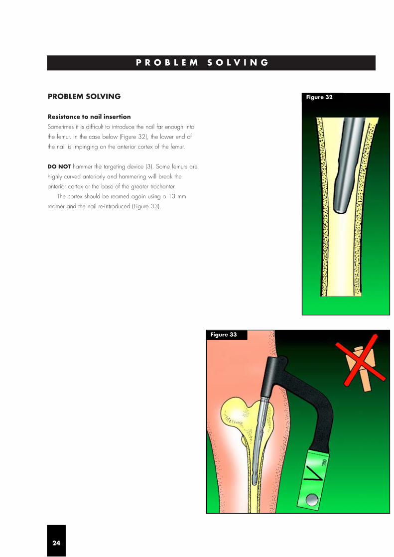
PROBLEM SOLVING
Resistance to nail insertion
Sometimes it is difficult to introduce the nail far enough into
the femur. In the case below (Figure 32), the lower end of
the nail is impinging on the anterior cortex of the femur.
DO NOT hammer the targeting device (3). Some femurs are
highly curved anteriorly and hammering will break the
anterior cortex or the base of the greater trochanter.
The cortex should be reamed again using a 13 mm
reamer and the nail re-introduced (Figure 33).
P R O B L E M S O L V I N G
24
Figure 32
Figure 33
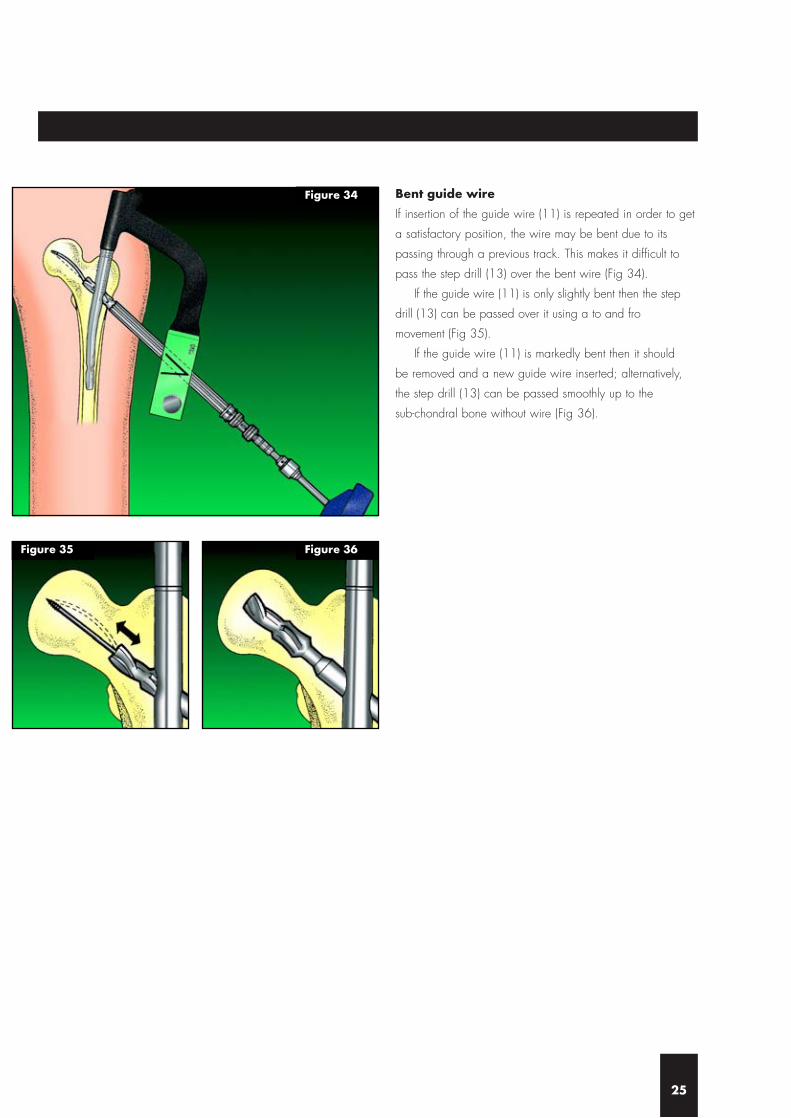
Bent guide wire
If insertion of the guide wire (11) is repeated in order to get
a satisfactory position, the wire may be bent due to its
passing through a previous track. This makes it difficult to
pass the step drill (13) over the bent wire (Fig 34).
If the guide wire (11) is only slightly bent then the step
drill (13) can be passed over it using a to and fro
movement (Fig 35).
If the guide wire (11) is markedly bent then it should
be removed and a new guide wire inserted; alternatively,
the step drill (13) can be passed smoothly up to the
sub-chondral bone without wire (Fig 36).
25
Figure 34
Figure 35 Figure 36

Posterior displacement
In the case of a comminuted fracture, there is a tendency for
the fracture to become displaced downwards, i.e.
posteriorly, making it difficult to pass the guide wire (11)
into the centre of the neck or head. This should be solved
by lifting the nail insertion targeting device (3).
Alternatively, the assistant could lift the greater trochanter
up with his hand, and support it with a sandbag. This will
maintain the neck and the femur in nearly the same axis, so
that it will be easy to pass the guide wire (11) through the
centre of the neck and head (Figures 37a, b, c). The
position should then be checked on both anterior-posterior
and lateral views using the image intensifier. Care is
required to avoid radiation risk to the assistant.
26
Figure 37a
Figure 37b
Figure 37c
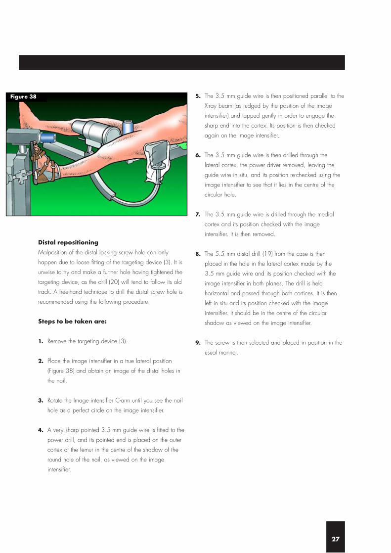
Distal repositioning
Malposition of the distal locking screw hole can only
happen due to loose fitting of the targeting device (3). It is
unwise to try and make a further hole having tightened the
targeting device, as the drill (20) will tend to follow its old
track. A free-hand technique to drill the distal screw hole is
recommended using the following procedure:
Steps to be taken are:
1. Remove the targeting device (3).
2. Place the image intensifier in a true lateral position
(Figure 38) and obtain an image of the distal holes in
the nail.
3. Rotate the Image intensifier C-arm until you see the nail
hole as a perfect circle on the image intensifier.
4. A very sharp pointed 3.5 mm guide wire is fitted to the
power drill, and its pointed end is placed on the outer
cortex of the femur in the centre of the shadow of the
round hole of the nail, as viewed on the image
intensifier.
5. The 3.5 mm guide wire is then positioned parallel to the
X-ray beam (as judged by the position of the image
intensifier) and tapped gently in order to engage the
sharp end into the cortex. Its position is then checked
again on the image intensifier.
6. The 3.5 mm guide wire is then drilled through the
lateral cortex, the power driver removed, leaving the
guide wire in situ, and its position re-checked using the
image intensifier to see that it lies in the centre of the
circular hole.
7. The 3.5 mm guide wire is drilled through the medial
cortex and its position checked with the image
intensifier. It is then removed.
8. The 5.5 mm distal drill (19) from the case is then
placed in the hole in the lateral cortex made by the
3.5 mm guide wire and its position checked with the
image intensifier in both planes. The drill is held
horizontal and passed through both cortices. It is then
left in situ and its position checked with the image
intensifier. It should be in the centre of the circular
shadow as viewed on the image intensifier.
9. The screw is then selected and placed in position in the
usual manner.
27
Figure 38

The Trochanteric Gamma® Nail has been available in a
new sterile packaging, since the autumn of 2001.
The nail is packed together with the set screw in one box,
because the use of the set screw is required in every case.
Cat No Description
1805-1125S Trochanteric Nail Kit 125°
1805-1130S Trochanteric Nail Kit 130°
1805-1135S Trochanteric Nail Kit 135°
S T E R I L E I M P L A N T S
28
I M P L A N T S & I N S T R U M E N T A T I O N
29
S= sterile
Note: For ‘non sterile’ products remove “S”
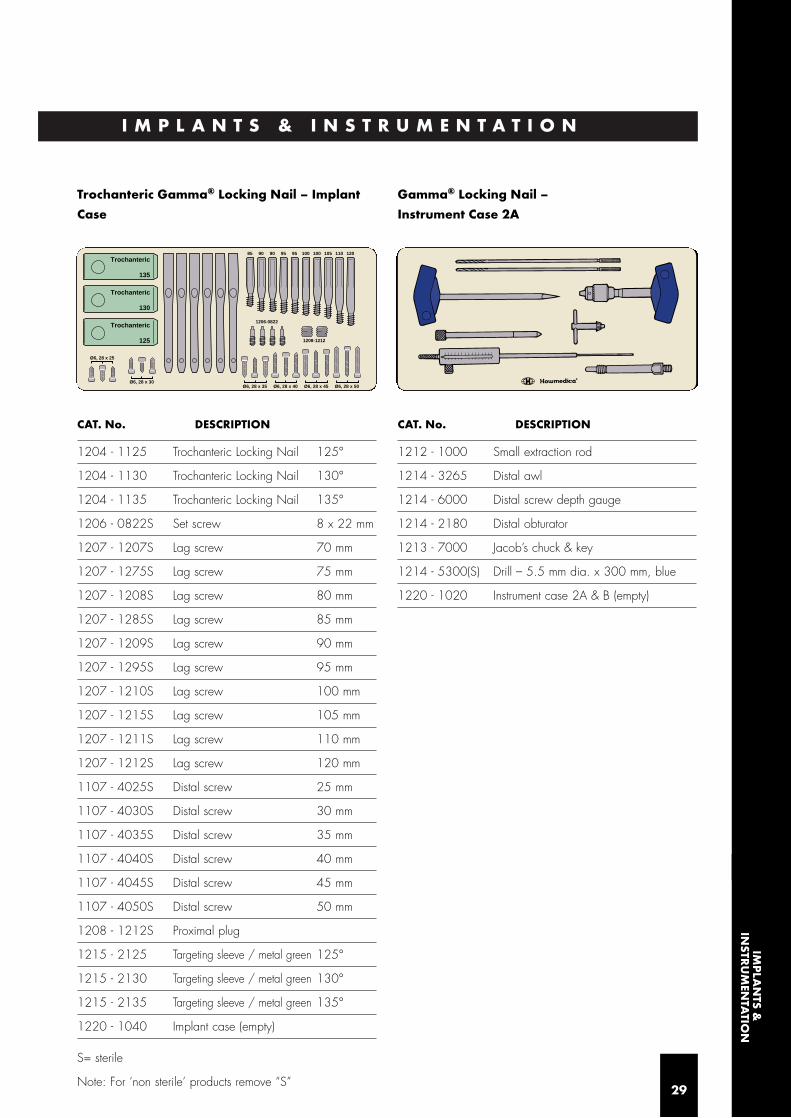
Trochanteric Gamma® Locking Nail – Implant
Case
CAT. No. DESCRIPTION
1204 - 1125 Trochanteric Locking Nail 125°
1204 - 1130 Trochanteric Locking Nail 130°
1204 - 1135 Trochanteric Locking Nail 135°
1206 - 0822S Set screw 8 x 22 mm
1207 - 1207S Lag screw 70 mm
1207 - 1275S Lag screw 75 mm
1207 - 1208S Lag screw 80 mm
1207 - 1285S Lag screw 85 mm
1207 - 1209S Lag screw 90 mm
1207 - 1295S Lag screw 95 mm
1207 - 1210S Lag screw 100 mm
1207 - 1215S Lag screw 105 mm
1207 - 1211S Lag screw 110 mm
1207 - 1212S Lag screw 120 mm
1107 - 4025S Distal screw 25 mm
1107 - 4030S Distal screw 30 mm
1107 - 4035S Distal screw 35 mm
1107 - 4040S Distal screw 40 mm
1107 - 4045S Distal screw 45 mm
1107 - 4050S Distal screw 50 mm
1208 - 1212S Proximal plug
1215 - 2125 Targeting sleeve / metal green 125°
1215 - 2130 Targeting sleeve / metal green 130°
1215 - 2135 Targeting sleeve / metal green 135°
1220 - 1040 Implant case (empty)
Gamma® Locking Nail –
Instrument Case 2A
CAT. No. DESCRIPTION
1212 - 1000 Small extraction rod
1214 - 3265 Distal awl
1214 - 6000 Distal screw depth gauge
1214 - 2180 Distal obturator
1213 - 7000 Jacob’s chuck & key
1214 - 5300(S) Drill – 5.5 mm dia. x 300 mm, blue
1220 - 1020 Instrument case 2A & B (empty)
135
Trochanteric
130
Trochanteric
125
Trochanteric
Ø6, 28 x 25
Ø6, 28 x 30Ø6, 28 x 35 Ø6, 28 x 40 Ø6, 28 x 45 Ø6, 28 x 50
1208-1212
1206-0822
1201101051001009595909085
IMP
LAN
TS &IN
STRU
MEN
TATIO
N

Gamma® Locking Nail –
Instrument Case 2B
CAT. No. DESCRIPTION
1213 - 1300 Socket wrench
1213 - 1304 Set screwdriver bit SW4
1210 - 3220 Lag screw guide sleeve
1213 - 4300 Lag screw awl
1210 - 5250 Kirschner wire guide sleeve
1210 - 6450(S) Kirschner wire 3.2 x 450 mm
1210 - 7190 Lag screw length gauge
1210 - 8100 Lag screw step drill
1213 - 9000 Lag screwdriver
Gamma® Locking Nail
– Instrument Case 3
CAT. No. DESCRIPTION
1213 - 1000 Carbon-fibre targeting device
1213 - 1100 Nail holding bolt
1213 - 1220 Screwdriver for nail holding bolt
1214 - 1160 Distal tissue protector
1213 - 2125 Targeting sleeve 125°
1213 - 2130 Targeting sleeve 130°
1213 - 2135 Targeting sleeve 135°
1214 - 4172 Drill guide sleeve 5.5 mm
1214 - 5300(S) Drill bit – 5.5 mm x 300 mm, blue
1214 - 7025 Distal screwdriver
1214 - 9000 Final Impactor
1220 - 1030 Instrument case 3 – empty
Not stored on tray
0121 - 0002 2-part curved awl
Note: The Standard Gamma Targeting Sleeves
(metal colour) are NOT for use with the Trochanteric
Gamma® Nail.
30

Optional Instruments not stored on tray
1213-3010 One Shot Device
1213-9090 Cannulated cutter
1213-9091 Guide pin for cannulated cutter,
4 mm x 400 mm
1214-4090 Prox. drill guide sleeve f. lag screw,
5.5 mm x 250 mm, blue
1215-2225 Trochanteric targeting sleeve 125°
(plastic)
1215-2230 Trochanteric targeting sleeve 130°
(plastic)
1215-2235 Trochanteric targeting sleeve 135°
(plastic)
1800-0150 Screwdriver, 5 mm x 250 mm,
self-retaining
1803-0030 Proximal femur drill, 17 mm x 300 mm
1803-0070 Proximal femur guide sleeve, 300 mm
1806-0040 Awl, curved
1806-0085S Guide wire 3.0 mm x 1000 mm,
ball tip
1806-0095 Guide wire handle
1806-0096 Guide wire handle chuck
3371-1085 Tap for lag screw
X-Ray Templates
1204-1000 X-ray template Trochanteric Gamma®
Nail (TGN)
1600-1000 X-ray template Long Gamma® Nail
(LGN)
1220-1055 Gamma Extraction Set, complete,
consists of:
1806-0110 Universal rod
1806-0130 Wrench 10/8 mm
1806-0175 Sliding hammer
1800-0150 Screwdriver, 5 mm x 250 mm, self-retaining
1407-1304 Inserter for set screw, self-retaining
1213-9000 Lag screwdriver
1213-1300 Socket wrench
1212-1010 Extraction rod conical
1220-1050 Gamma® extraction box
O P T I O N A L I N S T R U M E N T S
31
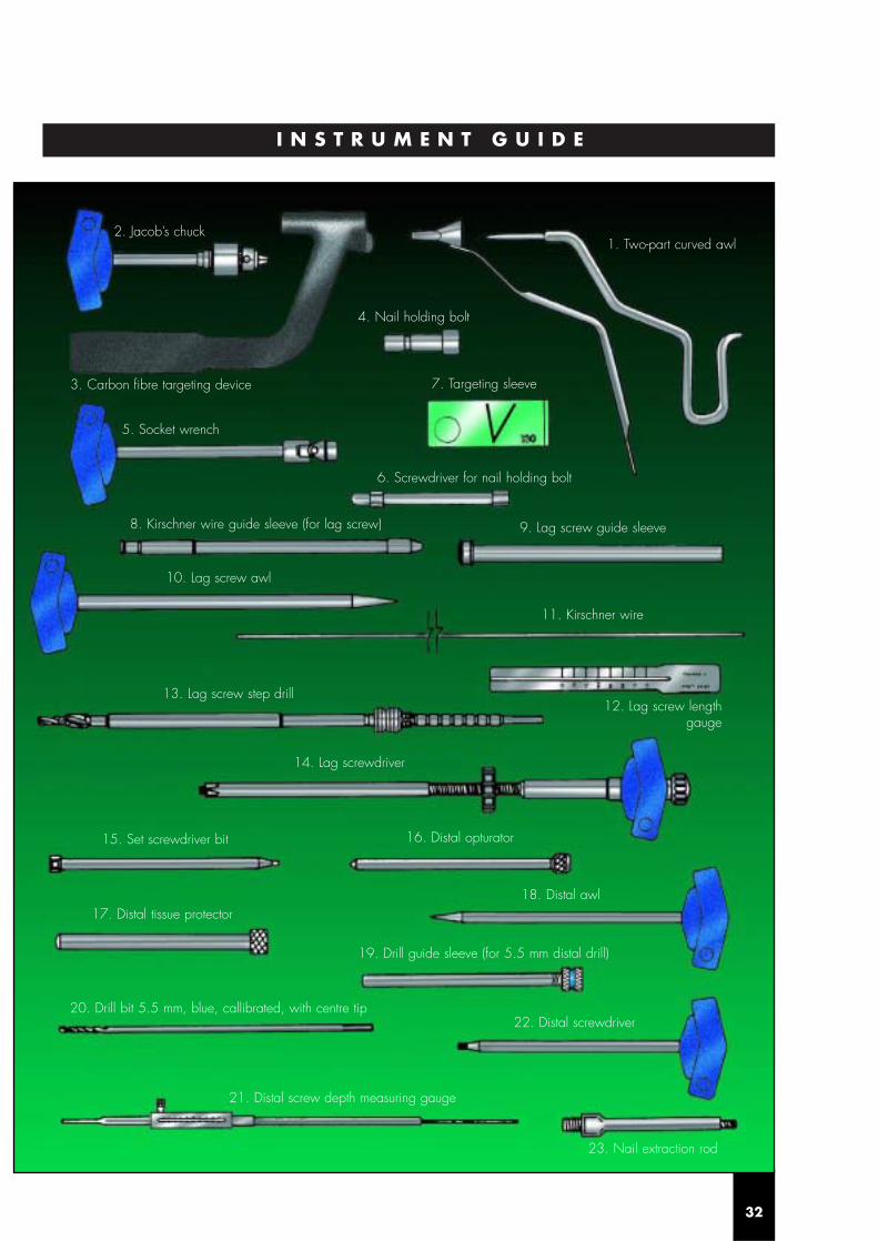
I N S T R U M E N T G U I D E
32
2. Jacob’s chuck1. Two-part curved awl
4. Nail holding bolt
3. Carbon fibre targeting device
5. Socket wrench
6. Screwdriver for nail holding bolt
7. Targeting sleeve
8. Kirschner wire guide sleeve (for lag screw) 9. Lag screw guide sleeve
10. Lag screw awl
11. Kirschner wire
13. Lag screw step drill
14. Lag screwdriver
15. Set screwdriver bit 16. Distal opturator
18. Distal awl17. Distal tissue protector
20. Drill bit 5.5 mm, blue, callibrated, with centre tip
19. Drill guide sleeve (for 5.5 mm distal drill)
22. Distal screwdriver
23. Nail extraction rod
21. Distal screw depth measuring gauge
12. Lag screw lengthgauge

D E V E L O P E D B Y S U R G E O N S – F O R F R A C T U R E S A R O U N D T H E T R O C H A N T E R
Fold out this page to show instrument guide for operating technique.
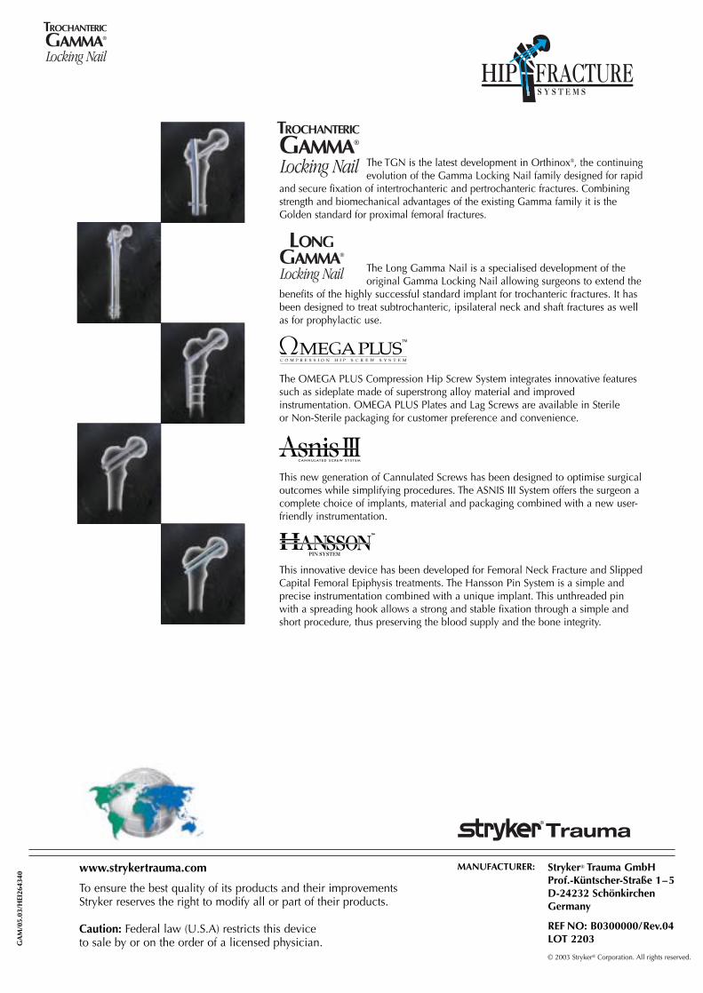
The TGN is the latest development in Orthinox®, the continuingevolution of the Gamma Locking Nail family designed for rapid
and secure fixation of intertrochanteric and pertrochanteric fractures. Combiningstrength and biomechanical advantages of the existing Gamma family it is theGolden standard for proximal femoral fractures.
The Long Gamma Nail is a specialised development of the original Gamma Locking Nail allowing surgeons to extend the
benefits of the highly successful standard implant for trochanteric fractures. It hasbeen designed to treat subtrochanteric, ipsilateral neck and shaft fractures as wellas for prophylactic use.
The OMEGA PLUS Compression Hip Screw System integrates innovative featuressuch as sideplate made of superstrong alloy material and improvedinstrumentation. OMEGA PLUS Plates and Lag Screws are available in Sterileor Non-Sterile packaging for customer preference and convenience.
This new generation of Cannulated Screws has been designed to optimise surgicaloutcomes while simplifying procedures. The ASNIS III System offers the surgeon acomplete choice of implants, material and packaging combined with a new user-friendly instrumentation.
This innovative device has been developed for Femoral Neck Fracture and SlippedCapital Femoral Epiphysis treatments. The Hansson Pin System is a simple andprecise instrumentation combined with a unique implant. This unthreaded pinwith a spreading hook allows a strong and stable fixation through a simple andshort procedure, thus preserving the blood supply and the bone integrity.
PIN SYSTEM
GA
M/0
5.03
/HEI
2643
40
Stryker® Trauma GmbHProf.-Küntscher-Straße 1–5D-24232 SchönkirchenGermany
REF NO: B0300000/Rev.04LOT 2203
© 2003 Stryker® Corporation. All rights reserved.
MANUFACTURER:www.strykertrauma.com
To ensure the best quality of its products and their improvements Stryker reserves the right to modify all or part of their products.
Caution: Federal law (U.S.A) restricts this deviceto sale by or on the order of a licensed physician.