th-7800 user manualftp1.linkdelight.com/th-7800英内0623.pdf · th-7800 user manual thank you very...
TRANSCRIPT

TH-7800 User ManualThank you very much for choosing the TH-7800 dual band mobile transceiver.
The TH-7800 provides you with a reliable, clear and efficient communications service
which in enhanced by an ergonomic design and intuitive user controls.
Inherently reliable you can depend on your TH-7800 no matter where you are in the
harsh environment.
The TH-7800 is cost-effective, multi-functional and will meet all of your VHF/UHF
band communication needs no matter what the situation.
For a full explanation of the many features, functions and the care free maintenance
of your new mobile please take the time to read the user manual enclosed with your
transceiver.
User Safety Information
Package includes
Main Features
Initial Installation
Mobile Installation
Installation methods
Mounting bracket installation
Separation cable connection
DC Power Cable Connection
Fixed Station Operation
Replacing Fuses
Antenna Connection
Accessories Connections
External Speaker
Microphone
Getting Acquainted
Front Panel Operation
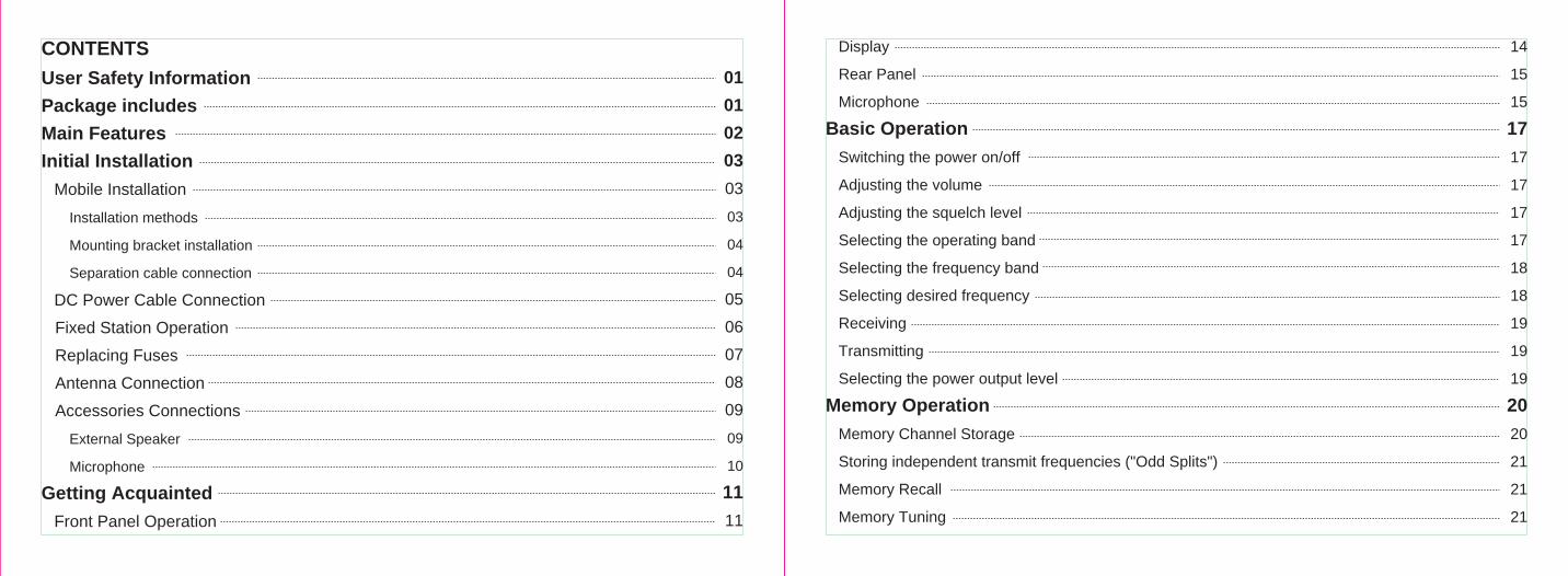
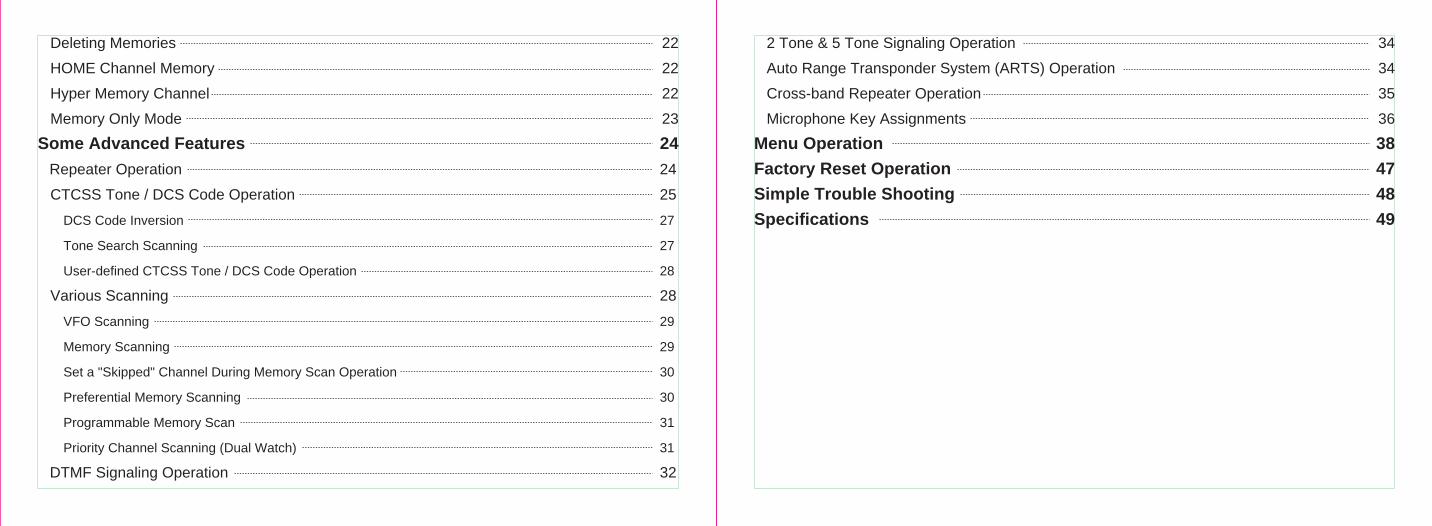
CONTENTS
01
01
02
03
03
03
04
04
05
06
07
08
09
09
10
11
11
Display
Rear Panel
Microphone
Basic Operation
Switching the power on/off
Adjusting the volume
Adjusting the squelch level
Selecting the operating band
Selecting the frequency band
Selecting desired frequency
Receiving
Transmitting
Selecting the power output level
Memory Operation
Memory Channel Storage
Storing independent transmit frequencies ("Odd Splits")
Memory Recall
Memory Tuning
14
15
15
17
17
17
17
17
18
18
19
19
19
20
20
21
21
21
Deleting Memories
HOME Channel Memory
Hyper Memory Channel
Memory Only Mode
Some Advanced Features
Repeater Operation
CTCSS Tone / DCS Code Operation
DCS Code Inversion
Tone Search Scanning
User-defined CTCSS Tone / DCS Code Operation
Various Scanning
VFO Scanning
Memory Scanning
Set a "Skipped" Channel During Memory Scan Operation
Preferential Memory Scanning
Programmable Memory Scan
Priority Channel Scanning (Dual Watch)
DTMF Signaling Operation
22
22
22
23
24
24
25
27
27
28
28
29
29
30
30
31
31
32
2 Tone & 5 Tone Signaling Operation
Auto Range Transponder System (ARTS) Operation
Cross-band Repeater Operation
Microphone Key Assignments
Menu Operation
Factory Reset Operation
Simple Trouble Shooting
Specifications
34
34
35
36
38
47
48
49
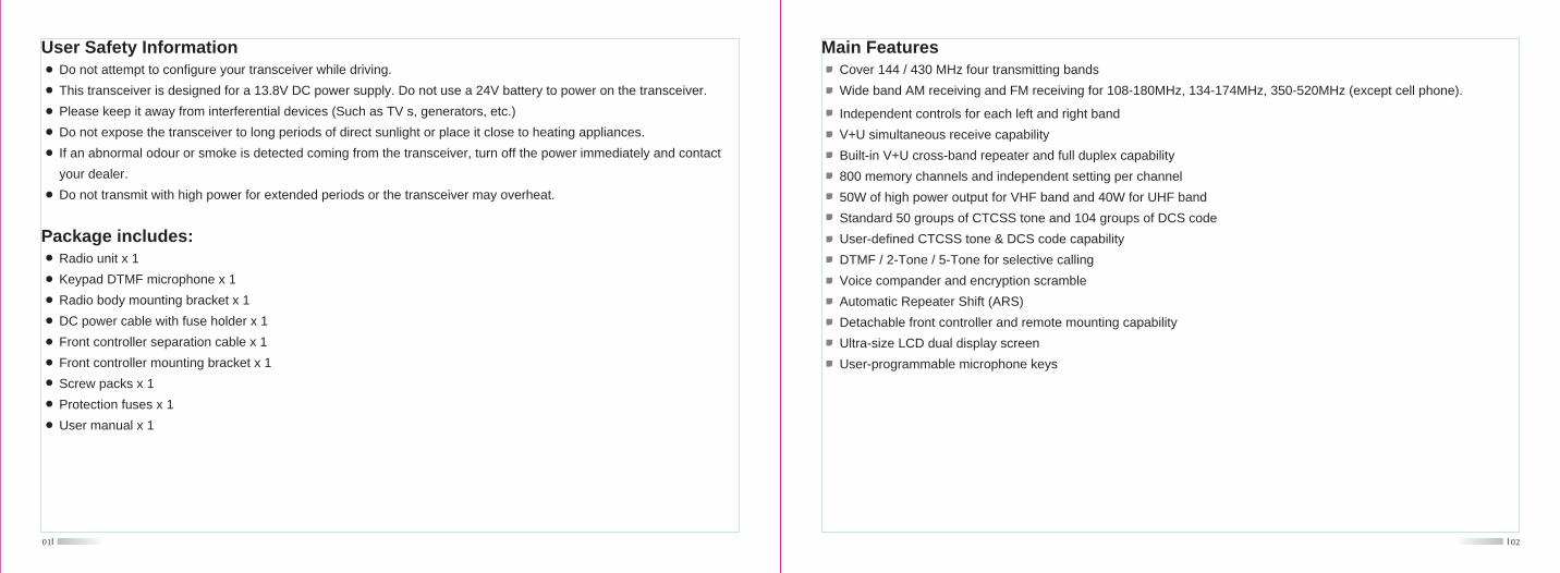
User Safety Information Do not attempt to configure your transceiver while driving.
This transceiver is designed for a 13.8V DC power supply. Do not use a 24V battery to power on the transceiver.
Please keep it away from interferential devices (Such as TV s, generators, etc.)
Do not expose the transceiver to long periods of direct sunlight or place it close to heating appliances.
If an abnormal odour or smoke is detected coming from the transceiver, turn off the power immediately and contact
your dealer.
Do not transmit with high power for extended periods or the transceiver may overheat.
01
Package includes: Radio unit x 1
Keypad DTMF microphone x 1
Radio body mounting bracket x 1
DC power cable with fuse holder x 1
Front controller separation cable x 1
Front controller mounting bracket x 1
Screw packs x 1
Protection fuses x 1
User manual x 1
02
Main Features Cover 144 / 430 MHz four transmitting bands
Wide band AM receiving and FM receiving for 108-180MHz, 134-174MHz, 350-520MHz (except cell phone).
Independent controls for each left and right band
V+U simultaneous receive capability
Built-in V+U cross-band repeater and full duplex capability
800 memory channels and independent setting per channel
50W of high power output for VHF band and 40W for UHF band
Standard 50 groups of CTCSS tone and 104 groups of DCS code
User-defined CTCSS tone & DCS code capability
DTMF / 2-Tone / 5-Tone for selective calling
Voice compander and encryption scramble
Automatic Repeater Shift (ARS)
Detachable front controller and remote mounting capability
Ultra-size LCD dual display screen
User-programmable microphone keys
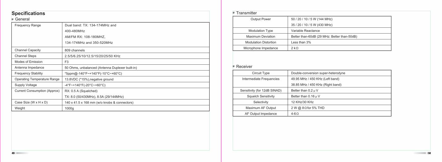
Transceiver
03
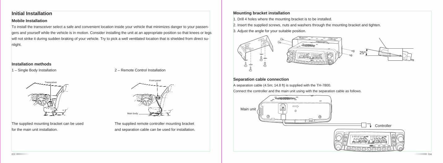
Initial InstallationMobile Installation
To install the transceiver select a safe and convenient location inside your vehicle that minimizes danger to your passen-
gers and yourself while the vehicle is in motion. Consider installing the unit at an appropriate position so that knees or legs
will not strike it during sudden braking of your vehicle. Try to pick a well ventilated location that is shielded from direct su-
nlight.
Installation methods
1 – Single Body Installation
The supplied mounting bracket can be used
for the main unit installation.
Front panel
Main body
2 – Remote Control Installation
The supplied remote controller mounting bracket
and separation cable can be used for installation.
Separation cable connection
A separation cable (4.5m; 14.8 ft) is supplied with the TH-7800.
Connect the controller and the main unit using with the separation cable as follows.
Main unit
04
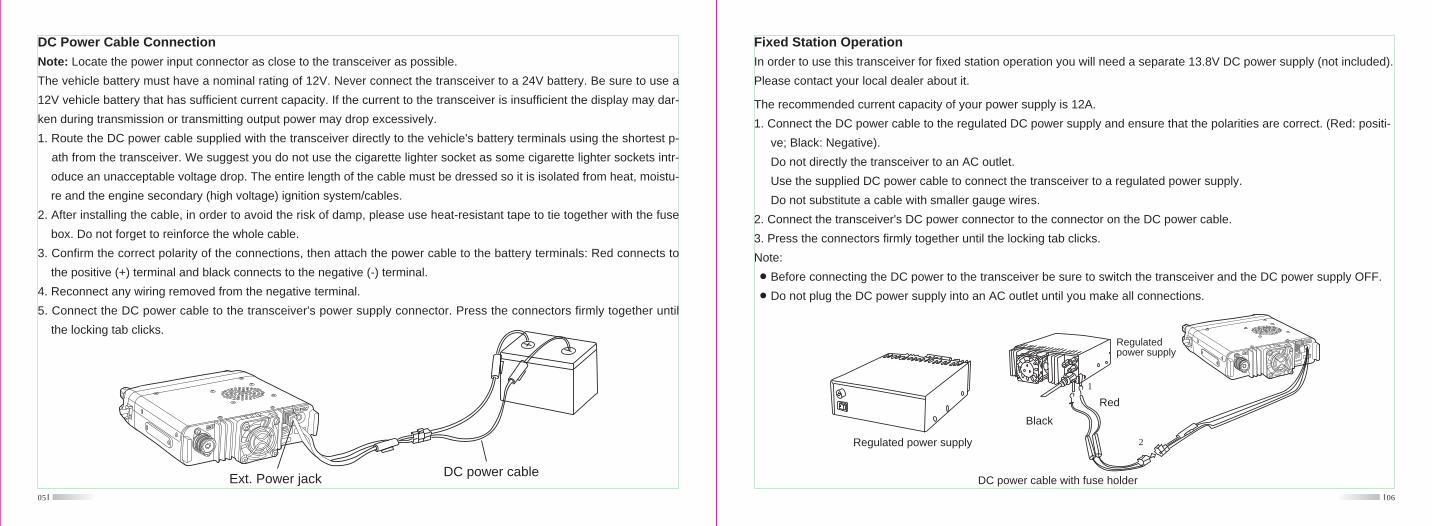
Mounting bracket installation
1. Drill 4 holes where the mounting bracket is to be installed.
2. Insert the supplied screws, nuts and washers through the mounting bracket and tighten.
3. Adjust the angle for your suitable position.
Controller
B
A
LOW V/M
C
HM SCN LOW V/M SCNHM
D
E
F
SQLVOL
RPT TONE SUBMHz
SQLVOL
25*B
A
LOW V/M
C
HM SCN LOW V/M SCNHM
D
E
FMHz RPT TONE SUB
05
DC Power Cable Connection
Note: Locate the power input connector as close to the transceiver as possible.
The vehicle battery must have a nominal rating of 12V. Never connect the transceiver to a 24V battery. Be sure to use a
12V vehicle battery that has sufficient current capacity. If the current to the transceiver is insufficient the display may dar-
ken during transmission or transmitting output power may drop excessively.
1. Route the DC power cable supplied with the transceiver directly to the vehicle's battery terminals using the shortest p-
ath from the transceiver. We suggest you do not use the cigarette lighter socket as some cigarette lighter sockets intr-
oduce an unacceptable voltage drop. The entire length of the cable must be dressed so it is isolated from heat, moistu-
re and the engine secondary (high voltage) ignition system/cables.
2. After installing the cable, in order to avoid the risk of damp, please use heat-resistant tape to tie together with the fuse
box. Do not forget to reinforce the whole cable.
3. Confirm the correct polarity of the connections, then attach the power cable to the battery terminals: Red connects to
the positive (+) terminal and black connects to the negative (-) terminal.
4. Reconnect any wiring removed from the negative terminal.
5. Connect the DC power cable to the transceiver's power supply connector. Press the connectors firmly together until
the locking tab clicks.
Ext. Power jack DC power cable
06
Fixed Station Operation
In order to use this transceiver for fixed station operation you will need a separate 13.8V DC power supply (not included).
Please contact your local dealer about it.
The recommended current capacity of your power supply is 12A.
1. Connect the DC power cable to the regulated DC power supply and ensure that the polarities are correct. (Red: positi-
ve; Black: Negative).
Do not directly the transceiver to an AC outlet.
Use the supplied DC power cable to connect the transceiver to a regulated power supply.
Do not substitute a cable with smaller gauge wires.
2. Connect the transceiver's DC power connector to the connector on the DC power cable.
3. Press the connectors firmly together until the locking tab clicks.
Note:
Before connecting the DC power to the transceiver be sure to switch the transceiver and the DC power supply OFF.
Do not plug the DC power supply into an AC outlet until you make all connections.
DC power cable with fuse holder
Regulated power supply
Black
Red
Regulatedpower supply
1
2
07
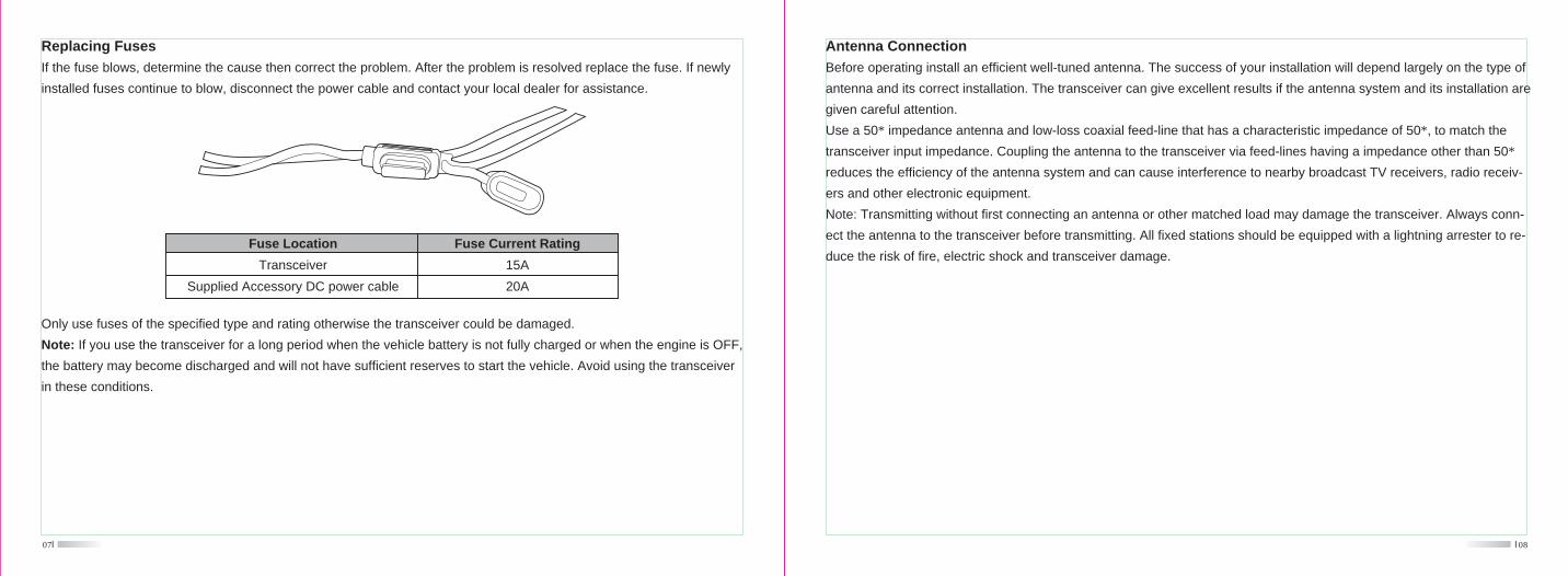
Replacing Fuses
If the fuse blows, determine the cause then correct the problem. After the problem is resolved replace the fuse. If newly
installed fuses continue to blow, disconnect the power cable and contact your local dealer for assistance.
Fuse Location
Transceiver
Supplied Accessory DC power cable
Fuse Current Rating
15A
20A
Only use fuses of the specified type and rating otherwise the transceiver could be damaged.
Note: If you use the transceiver for a long period when the vehicle battery is not fully charged or when the engine is OFF,
the battery may become discharged and will not have sufficient reserves to start the vehicle. Avoid using the transceiver
in these conditions.
08
Antenna Connection
Before operating install an efficient well-tuned antenna. The success of your installation will depend largely on the type of
antenna and its correct installation. The transceiver can give excellent results if the antenna system and its installation are
given careful attention.
Use a 50* impedance antenna and low-loss coaxial feed-line that has a characteristic impedance of 50*, to match the
transceiver input impedance. Coupling the antenna to the transceiver via feed-lines having a impedance other than 50*
reduces the efficiency of the antenna system and can cause interference to nearby broadcast TV receivers, radio receiv-
ers and other electronic equipment.
Note: Transmitting without first connecting an antenna or other matched load may damage the transceiver. Always conn-
ect the antenna to the transceiver before transmitting. All fixed stations should be equipped with a lightning arrester to re-
duce the risk of fire, electric shock and transceiver damage.
09
Accessories ConnectionsExternal Speaker
If you plan to use an external speaker, choose a speaker with an impedance of 8*. The external speaker jack accepts a
3.5mm mono (2-conductor) plug.
Note: External speaker output adopts double port BTL. Please be aware that the speaker can't connect to the ground oth-
erwise the speaker will fault. The wrong connection way is as below:
Error
Ground
10
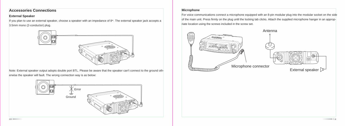
Microphone
For voice communications connect a microphone equipped with an 8-pin modular plug into the modular socket on the side
of the main unit. Press firmly on the plug until the locking tab clicks. Attach the supplied microphone hanger in an approp-
riate location using the screws included in the screw set.
Microphone connector
MIC
1 2 3
4 5 6
7 8 9
0 #
A
B
C
D
P1
P 2
P 3 P 4
Antenna
External speaker
B
A
LOW V/M
C
HM SCNLOW V/M SCNHM
D
E
FMHz RPT TONE SUB
11
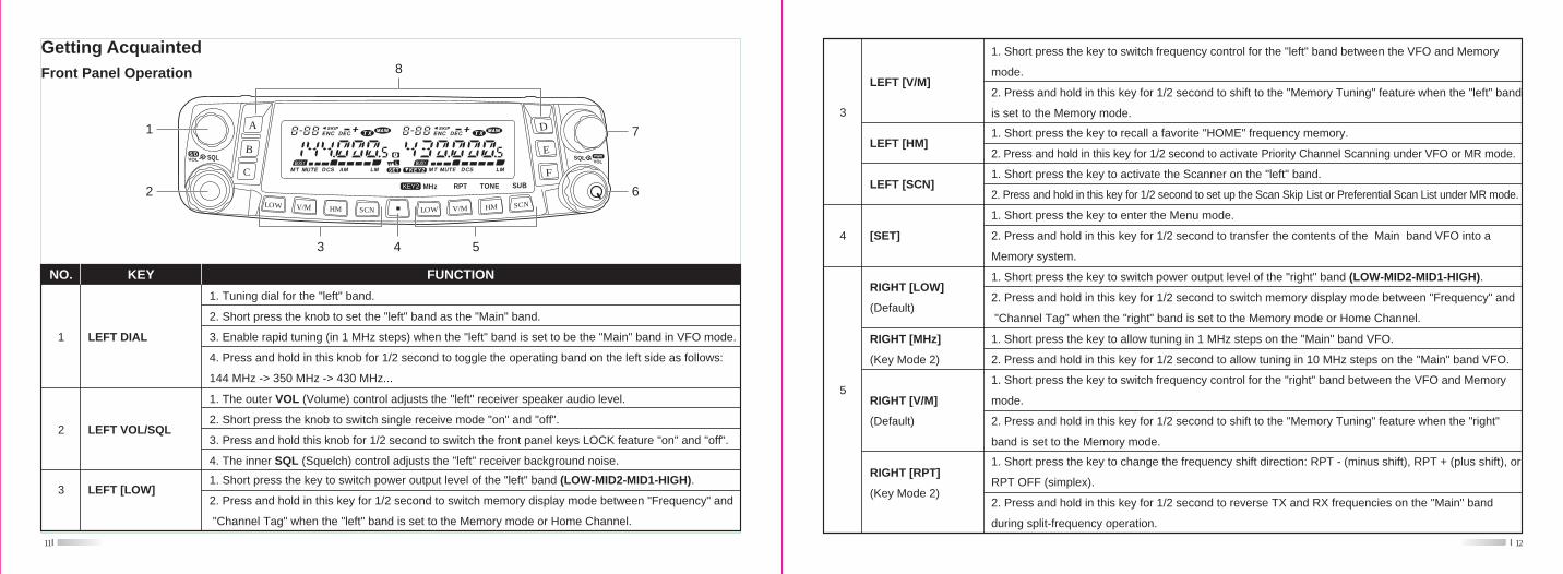
Getting AcquaintedFront Panel Operation
B
A
LOW V/M
C
HM SCN LOW V/M SCNHM
D
E
FMHz RPT TONE SUB
SQLVOL
SQLVOL
43 5
6
7
8
2
1
1
FUNCTION
LEFT DIAL
1. Tuning dial for the "left" band.
2. Short press the knob to set the "left" band as the "Main" band.
3. Enable rapid tuning (in 1 MHz steps) when the "left" band is set to be the "Main" band in VFO mode.
4. Press and hold in this knob for 1/2 second to toggle the operating band on the left side as follows:
144 MHz -> 350 MHz -> 430 MHz...
NO. KEY
1. The outer VOL (Volume) control adjusts the "left" receiver speaker audio level.
2. Short press the knob to switch single receive mode "on" and "off".
3. Press and hold this knob for 1/2 second to switch the front panel keys LOCK feature "on" and "off".
4. The inner SQL (Squelch) control adjusts the "left" receiver background noise.
LEFT VOL/SQL2
LEFT [LOW]1. Short press the key to switch power output level of the "left" band (LOW-MID2-MID1-HIGH).
2. Press and hold in this key for 1/2 second to switch memory display mode between "Frequency" and
"Channel Tag" when the "left" band is set to the Memory mode or Home Channel.
3
12
3
LEFT [V/M]
LEFT [SCN]
LEFT [HM]
1. Short press the key to switch frequency control for the "left" band between the VFO and Memory
mode.
2. Press and hold in this key for 1/2 second to shift to the "Memory Tuning" feature when the "left" band
is set to the Memory mode.
1. Short press the key to recall a favorite "HOME" frequency memory.
2. Press and hold in this key for 1/2 second to activate Priority Channel Scanning under VFO or MR mode.
1. Short press the key to activate the Scanner on the "left" band.
2. Press and hold in this key for 1/2 second to set up the Scan Skip List or Preferential Scan List under MR mode.
1. Short press the key to enter the Menu mode.
2. Press and hold in this key for 1/2 second to transfer the contents of the Main band VFO into a
Memory system.
[SET]4
RIGHT [LOW]
(Default)
RIGHT [MHz]
(Key Mode 2)
RIGHT [V/M]
(Default)
RIGHT [RPT]
(Key Mode 2)
5
1. Short press the key to switch power output level of the "right" band (LOW-MID2-MID1-HIGH).
2. Press and hold in this key for 1/2 second to switch memory display mode between "Frequency" and
"Channel Tag" when the "right" band is set to the Memory mode or Home Channel.
1. Short press the key to allow tuning in 1 MHz steps on the "Main" band VFO.
2. Press and hold in this key for 1/2 second to allow tuning in 10 MHz steps on the "Main" band VFO.
1. Short press the key to switch frequency control for the "right" band between the VFO and Memory
mode.
2. Press and hold in this key for 1/2 second to shift to the "Memory Tuning" feature when the "right"
band is set to the Memory mode.
1. Short press the key to change the frequency shift direction: RPT - (minus shift), RPT + (plus shift), or
RPT OFF (simplex).
2. Press and hold in this key for 1/2 second to reverse TX and RX frequencies on the "Main" band
during split-frequency operation.
13
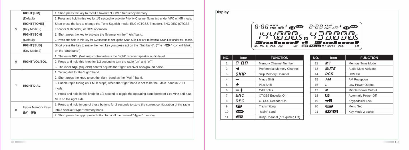
Hyper Memory Keys
([A] - [F])
1. The outer VOL (Volume) control adjusts the "right" receiver speaker audio level.
2. Press and hold this knob for 1/2 second to turn the radio "on" and "off".
3. The inner SQL (Squelch) control adjusts the "right" receiver background noise.
8
5
RIGHT [HM]
(Default)
RIGHT [TONE]
(Key Mode 2)
RIGHT [SCN]
(Default)
RIGHT [SUB]
(Key Mode 2)
1. Short press the key to recall a favorite "HOME" frequency memory.
2. Press and hold in this key for 1/2 second to activate Priority Channel Scanning under VFO or MR mode.
Short press the key to change the Tone Squelch mode: ENC (CTCSS Encoder), ENC DEC (CTCSS
Encoder & Decoder) or DCS operation.
1. Short press the key to activate the Scanner on the "right" band.
2. Press and hold in this key for 1/2 second to set up the Scan Skip List or Preferential Scan List under MR mode.
Short press the key to make the next key you press act on the "Sub band". (The " " icon will blink
on the "Sub band")
6 RIGHT VOL/SQL
1. Tuning dial for the "right" band.
2. Short press the knob to set the right band as the "Main" band.
3. Enable rapid tuning (in 1 MHz steps) when the "right" band is set to be the Main band in VFO
mode.
4. Press and hold in this knob for 1/2 second to toggle the operating band between 144 MHz and 430
MHz on the right side.
1. Press and hold in one of these buttons for 2 seconds to store the current configuration of the radio
into a special "Hyper" memory bank.
2. Short press the appropriate button to recall the desired "Hyper" memory.
RIGHT DIAL7
14
Display
12
13
14
15
16
17
18
19
20
21
Icon
Memory Tune Mode
Audio Mute Activate
DCS On
AM Reception
Low Power Output
Middle Power Output
Automatic Power-Off
Keypad/Dial Lock
Menu Set
Key Mode 2 active
FUNCTIONNO.
1
2
3
4
5
6
7
8
9
10
11
Icon
Memory Channel Number
Preferential Memory Channel
Skip Memory Channel
Minus Shift
Plus Shift
Odd Splits
CTCSS Encoder On
CTCSS Decoder On
Transmitting
"Main" Band
Busy Channel (or Squelch Off)
FUNCTIONNO.
15
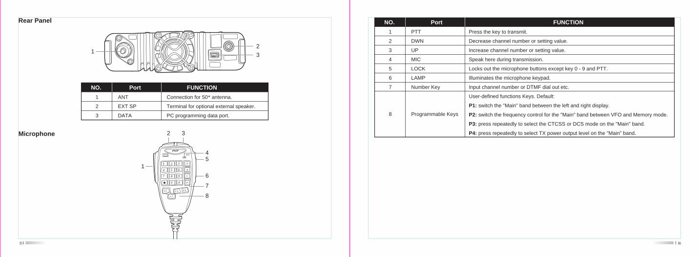
Rear Panel
Microphone
MIC
1 2 3
4 5 6
7 8 9
0 #
A
B
C
D
P1
P 2
P 3 P4
2 3
1
8
7
6
54
1
2
3
Port FUNCTIONNO.
Connection for 50* antenna.
Terminal for optional external speaker.
PC programming data port.
ANT
EXT SP
DATA
12
3
16
1
2
3
4
5
6
7
Port FUNCTIONNO.
PTT
DWN
UP
MIC
LOCK
LAMP
Number Key
Press the key to transmit.
Decrease channel number or setting value.
Increase channel number or setting value.
Speak here during transmission.
Locks out the microphone buttons except key 0 - 9 and PTT.
Illuminates the microphone keypad.
Input channel number or DTMF dial out etc.
User-defined functions Keys. Default:
P1: switch the "Main" band between the left and right display.
P2: switch the frequency control for the "Main" band between VFO and Memory mode.
P3: press repeatedly to select the CTCSS or DCS mode on the "Main" band.
P4: press repeatedly to select TX power output level on the "Main" band.
Programmable Keys8
17
Basic OperationSwitching the power on/off
To turn the mobile power ON press and hold the RIGHT VOL/SQL knob for 1/2 second.
To turn the mobile power OFF press and hold the RIGHT VOL/SQL knob for 1/2 second again.
Adjusting the volume
Turn the outer VOL control clockwise to increase the receiver speaker audio level and counter clockwise to decrease it.
Note:
1. Volume can be adjusted more accurately during communication.
2. The audio volume level is set independently by the LEFT and RIGHT VOL control.
Adjusting the squelch level
Turn the inner SQL control clockwise to increase the receiver background noise and counter clockwise to decrease it.
Note:
The squelch level is also set independently by the LEFT and RIGHT SQL control.
Selecting the operating band
In the factory default configuration, the TH-7800 operates in the "Dual Receive" mode.
During Dual Receive operation, the "Main" band frequency (on which transmission is possible) will be indicated by the
" " icon.
Short press the microphone's [P1] key or press the DIAL knob for the "left" or "right" side, the " " icon will light up alt-
ernative sides of the display as you switch "Main" bands from the "left" side to the "right" side, and vice-versa.
Note:
Short press the LEFT VOL/SQL knob to switch the single receive mode ON and OFF. When it is set ON, the working vol-
18
tage will be shown on the "sub" band, the " " icon will appear on the display, and LEFT [LOW], [V/M], [HM], [SCN],
RIGHT [MHz], [RPT], [TONE] keys will be valid for the operating band.
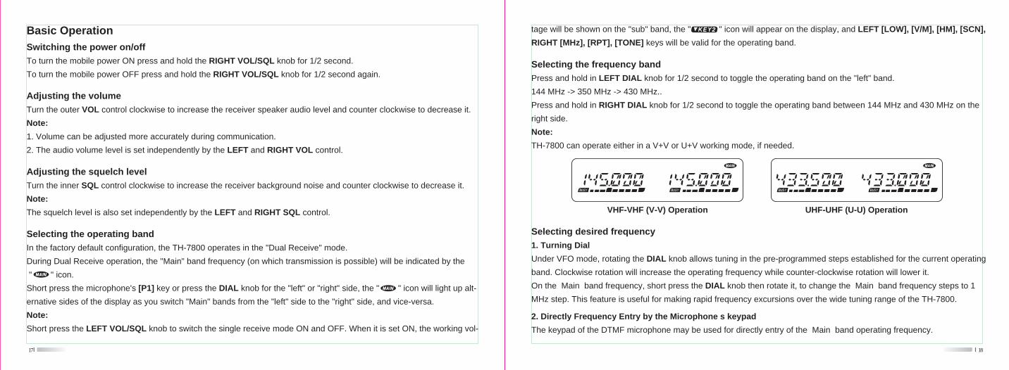
Selecting the frequency band
Press and hold in LEFT DIAL knob for 1/2 second to toggle the operating band on the "left" band.
144 MHz -> 350 MHz -> 430 MHz..
Press and hold in RIGHT DIAL knob for 1/2 second to toggle the operating band between 144 MHz and 430 MHz on the
right side.
Note:
TH-7800 can operate either in a V+V or U+V working mode, if needed.
VHF-VHF (V-V) Operation UHF-UHF (U-U) Operation
Selecting desired frequency
1. Turning Dial
Under VFO mode, rotating the DIAL knob allows tuning in the pre-programmed steps established for the current operating
band. Clockwise rotation will increase the operating frequency while counter-clockwise rotation will lower it.
On the Main band frequency, short press the DIAL knob then rotate it, to change the Main band frequency steps to 1
MHz step. This feature is useful for making rapid frequency excursions over the wide tuning range of the TH-7800.
2. Directly Frequency Entry by the Microphone s keypad
The keypad of the DTMF microphone may be used for directly entry of the Main band operating frequency.
19
Selecting the power output level
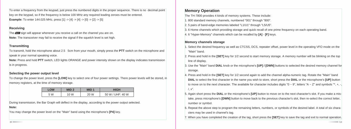
To change the power level, press the [LOW] key to select one of four power settings. There power levels will be stored, in
memory registers, at the time of memory storage.
To enter a frequency from the keypad, just press the numbered digits in the proper sequence. There is no decimal point
key on the keypad, so if the frequency is below 100 MHz any required leading zeroes must be entered.
Example: To enter 144.025 MHz, press [1] -> [4] -> [4] -> [0] -> [2] -> [5]
Receiving
The sign will appear whenever you receive a call on the channel you are on.
Note: The transceiver may fail to receive the signal if the squelch level is set high.
Transmitting
To transmit, hold the microphone about 2.5 5cm from your mouth, simply press the PTT switch on the microphone and
speak in your normal speaking voice.
Note: Press and hold PTT switch, LED lights ORANGE and power intensity shown on the display indicates transmission
is in progress.
HIGH
50 W / UHF: 40 W
LOW
5 W
MID 2
10 W
MID 1
20 W
During transmission, the Bar Graph will deflect in the display, according to the power output selected.
Note:
You may change the power level on the "Main" band using the microphone's [P4] key.
20
Memory OperationThe TH-7800 provides 4 kinds of memory systems. These include:
1. 800 standard memory channels, numbered "001" through "800".
2. 5 pairs of band-edge memories labeled "L1/U1" through "L5/U5".
3. 6 Home channels which providing storage and quick recall of one prime frequency on each operating band.
4. 6 "Hyper-Memory" channels which can be recalled by [A] - [F] keys.
Memory channels storage
1. Select the desired frequency as well as CTCSS, DCS, repeater offset, power level in the operating VFO mode on the
"Main" band.
2. Press and hold in the [SET] key for 1/2 second to start memory storage. A memory number will be blinking on the top
line of display.
3. Use the "Main" band DIAL knob or the microphone's [UP] / [DWN] buttons to selected the desired memory channel for
storage.
4. Press and hold in the [SET] key for 1/2 second again to add the channel alpha-numeric tag. Rotate the "Main" band
DIAL to select the first character in the name you wish to store, short press the DIAL or the microphone's [UP] button
to move on to the next character. The available for character includes digits "0 ~ 9", letters "A ~ Z" and symbols "*, +, -,
/, x".
5. Again short press the DIAL or the microphone's [UP] button to move on to the next character's slot. If you make a mis-
take, press microphone's [DWN] button to move back to the previous character's slot, then re-select the correct letter,
number or symbol.
6. Repeat the above step to program the remaining letters, numbers, or symbols of the desired label. A total of six chara-
cters may be used in channel's tag.
7. When you have completed the creation of the tag, short press the [SET] key to save the tag and exit to normal operation.
21
Note:
If you don't want to attach a alpha name tag to the memory, short press the [SET] key directly after Step 3, to save the
entry and exit to normal operation.
Storing independent transmit frequencies ("Odd Splits")
1. Store the receiving frequency as the steps already described.
2. Turn to the desired transmit frequency on the "Main" band, then press and hold in the [SET] key for 1/2 second.
3. Use the "Main" band DIAL knob or microphone's [UP] / [DWN] buttons to select the same memory channel number as
used in Step 1 above.
4. Press and hold in the PTT switch, then short press [SET] while holding the PTT switch to save the entry and exit to no-
rmal operation. The " " icon will appear on the channel.
Note:
Whenever you recall a memory which contains independent-stored transmit and receive frequencies, the " " icon will
appear in the display.
Memory Recall
1. While operating in the VFO mode, short press the [V/M] key to enter the Memory mode.
2. Rotate the DIAL knob or enter the microphone's key in the memory channel number to select the desired channel.
Note:
Memory channels on which you may have stored frequencies on the 29 MHz and 50 MHz two bands can not be recalled
on the "right" band.
Memory Tuning
1. Select the desired memory channel under MR (Memory Recall) mode
2. Press and hold in the [V/M] key for 1/2 second; the " " icon will appear on the display.22
3. Rotate the DIAL knob to turn to a new frequency. The synthesizer steps selected for VFO operation on the current band
will be the steps used during Memory Tuning.
4. Short press [V/M] key again and exit Memory Tuning. The " " icon will disappear.
Deleting Memories
1. Short press [V/M] key to enter the Memory mode.
2. Press and hold in the [SET] key for 1/2 second, then rotate the "Main" band DIAL to select the memory channel to be
selected. Note that memory channel #1 may not be deleted.
3. Short press the "Main" band [SCN] key to delete the channel selected. The display will revert to memory channel #1.
Rotate the DIAL knob to the channel you just deleted, you will observe that it is invisible now.
HOME Channel Memory
The TH-7800 allows quick recall of a favorite operating frequency on each band, called HOME channel (one for each of
the 6 operating bands).
1. Select the desired frequency as well as CTCSS, DCS, repeater offset, power level in the operating VFO mode on the
"Main" band.
2. Press and hold in the [SET] key for 1/2 second to start memory storage. A memory number will be blinking on the top
line of display.
3. Short press the "Main" [HM] key to store the VFO frequencies and other data in the special HOME channel register.
4. Repeat the steps above on the other operating bands.
5. To recall the HOME channel, just press the [H/M] key while operating either in the VFO or MR mode.
Hyper Memory Channel
The TH-7800 allows you to store the total current configuration of the radio into a special "Hyper" memory bank, including
operating frequency, CTCSS/DCS data, repeater shift, power level, scanning feature, menu setting...etc. for both the "left"
24
Some Advanced FeaturesRepeater Operation
The TH-7800 provides a convenient Automatic Repeater Shift feature, which causes the appropriate repeater shift to be
automatically applied whenever you tune into the designed repeater sub-bands in your country.
To activate ARS:
1. Short press the [SET] key to enter the Menu mode.
2. Rotate the "Main" band DIAL to select Menu # 2 (ARS).
3. Short press the "Main" band DIAL knob, then rotate the "Main" band DIAL to change the setting to "ON".
4. Short press the [SET] key to save the new setting and exit to normal operation.
If the ARS feature has been disabled, or if you need to set a repeater shift direction other than that established by the ARS,
you may set the direction of the repeater shift manually.
1. Short press the [SET] key to enter the Menu mode.
2. Rotate the "Main" band DIAL to select Menu # 24 (RPT.MOD).
3. Short press the "Main" band DIAL knob, then rotate the "Main" band DIAL to select the desired shift among "+", "-" and
"OFF".
4. Short press the [SET] key to save the new setting and exit to normal operation.
And when you travel to a different region, you may need to change the default repeater shift so as to ensure compatibility
with local operating requirements.
1. Short press the [SET] key to enter the Menu mode.
2. Rotate the "Main" band DIAL to select Menu # 27 (RPT.MOD).
3. Short press the "Main" band DIAL knob, then rotate the "Main" band DIAL to select the desired shift among "+", "-" and
"OFF".
4. Short press the [SET] key to save the new setting and exit to normal operation.23
Memory Only Mode
When you store the memory channels, you may place the radio in a "Memory Only" mode, whereby VFO operation is im-
possible. This may be particularly useful during public-service events where a number of operators may be using the radio
for first time, and ultimate simplicity of channel selection is desired.
Procedure:
1. Turn the radio off.
2. Press and hold in the LEFT [V/M] while turning the radio on.
3. Rotate the DIAL knob to select the (F-5 M-ONLY MODE), then short press the [SET] key to confirm. The radio will res-
tart and enter Memory Only Mode.
4. To return to normal operation, repeat the above steps.
and "right" bands.
1. Set up the desired configuration for both the "left" and "right" bands.
2. Press and hold in the one of the Hyper Memory keys ([A] ~ [F]) for 2 seconds to store into the Hyper Memory channel
which you wish to store that configuration.
3. Press the appropriate Hyper Memory Key [A] - [F] to recall the desired Hyper Memory channel. Please store the curre-
nt configuration into Hyper Memory Channel before recalling the Hyper Memory Channel to prevent the current config-
uration lost.
26
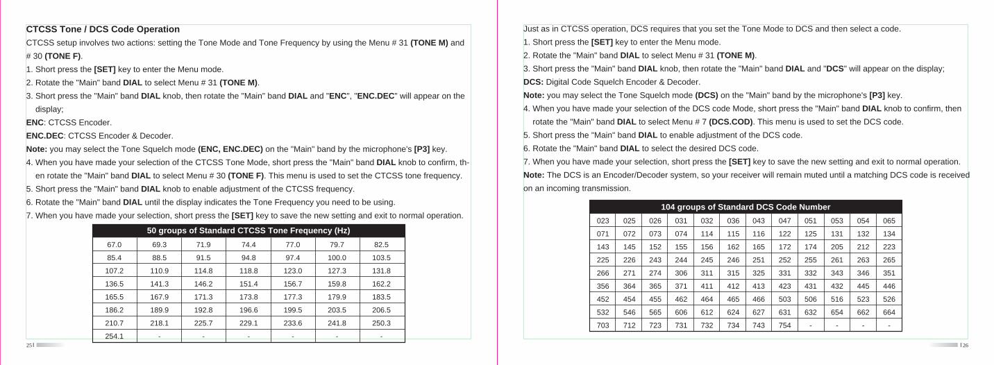
Just as in CTCSS operation, DCS requires that you set the Tone Mode to DCS and then select a code.
1. Short press the [SET] key to enter the Menu mode.
2. Rotate the "Main" band DIAL to select Menu # 31 (TONE M).
3. Short press the "Main" band DIAL knob, then rotate the "Main" band DIAL and "DCS" will appear on the display;
DCS: Digital Code Squelch Encoder & Decoder.
Note: you may select the Tone Squelch mode (DCS) on the "Main" band by the microphone's [P3] key.
4. When you have made your selection of the DCS code Mode, short press the "Main" band DIAL knob to confirm, then
rotate the "Main" band DIAL to select Menu # 7 (DCS.COD). This menu is used to set the DCS code.
5. Short press the "Main" band DIAL to enable adjustment of the DCS code.
6. Rotate the "Main" band DIAL to select the desired DCS code.
7. When you have made your selection, short press the [SET] key to save the new setting and exit to normal operation.
Note: The DCS is an Encoder/Decoder system, so your receiver will remain muted until a matching DCS code is received
on an incoming transmission.
104 groups of Standard DCS Code Number
023
071
143
225
266
356
452
532
703
025
072
145
226
271
364
454
546
712
026
073
152
243
274
365
455
565
723
031
074
155
244
306
371
462
606
731
032
114
156
245
311
411
464
612
732
036
115
162
246
315
412
465
624
734
043
116
165
251
325
413
466
627
743
047
122
172
252
331
423
503
631
754
051
125
174
255
332
431
506
632
-
053
131
205
261
343
432
516
654
-
054
132
212
263
346
445
523
662
-
065
134
223
265
351
446
526
664
-
25
CTCSS Tone / DCS Code Operation
CTCSS setup involves two actions: setting the Tone Mode and Tone Frequency by using the Menu # 31 (TONE M) and
# 30 (TONE F).
1. Short press the [SET] key to enter the Menu mode.
2. Rotate the "Main" band DIAL to select Menu # 31 (TONE M).
3. Short press the "Main" band DIAL knob, then rotate the "Main" band DIAL and "ENC", "ENC.DEC" will appear on the
display;
ENC: CTCSS Encoder.
ENC.DEC: CTCSS Encoder & Decoder.
Note: you may select the Tone Squelch mode (ENC, ENC.DEC) on the "Main" band by the microphone's [P3] key.
4. When you have made your selection of the CTCSS Tone Mode, short press the "Main" band DIAL knob to confirm, th-
en rotate the "Main" band DIAL to select Menu # 30 (TONE F). This menu is used to set the CTCSS tone frequency.
5. Short press the "Main" band DIAL knob to enable adjustment of the CTCSS frequency.
6. Rotate the "Main" band DIAL until the display indicates the Tone Frequency you need to be using.
7. When you have made your selection, short press the [SET] key to save the new setting and exit to normal operation.
50 groups of Standard CTCSS Tone Frequency (Hz)
67.0
85.4
107.2
136.5
165.5
186.2
210.7
254.1
69.3
88.5
110.9
141.3
167.9
189.9
218.1
-
71.9
91.5
114.8
146.2
171.3
192.8
225.7
-
82.5
103.5
131.8
162.2
183.5
206.5
250.3
-
74.4
94.8
118.8
151.4
173.8
196.6
229.1
-
77.0
97.4
123.0
156.7
177.3
199.5
233.6
-
79.7
100.0
127.3
159.8
179.9
203.5
241.8
-
28
6. When the radio detects the correct tone or code, it will halt on that tone/code, and audio will be allowed to pass. Short
press the "Main" band DIAL to lock in that tone/code, then press the [SET] key to save the new setting and exit to nor-
mal operation.
Note: If the Tone scan feature does not detect a tone or code, it will continue to scan. When this happens, it may be that
the other station is not sending any tone. Press the [SCN] key to halt the scan at any time.
User-defined CTCSS Tone / DCS Code Operation
The TH-7800 has the user-defined CTCSS Tone / DCS Code capability.
For CTCSS Tone:
1. Short press [SET] key to enter the Menu mode.
2. Rotate the "Main" band DIAL to select Menu # 30 (TONE F), short press the "Main" band DIAL knob to enter adjustment.
3. Input the Tone frequency by the microphone's key directly. The range is from 60.0 - 260.0 Hz.
4. Press the [SET] key to save the new setting and exit to normal operation.
For DCS Code:
1. Short press [SET] key to enter the Menu mode.
2. Rotate the "Main" band DIAL to select Menu # 7 (DCS.COD), short press the "Main" band DIAL knob to enter adjustm-
ent.
3. Input the DCS code number by the microphone s key directly. The range is from 000 - 777 Normal & Inverted, totally
1024 groups.
4. Press the [SET] key to save the new setting and exit to normal operation.
Various Scanning
The TH-7800 allows you to scan just the memory channels, the entire operating band, or a portion of that band. It will halt
on signals encountered, so you can talk to the station(s) on that frequency, if you like.
27
DCS Code Inversion
If you find that the TH-7800 receiver squelch does not open when both you and the other station are using a common DCS
code, you can try the following:
1. Short press the [SET] key to enter the Menu mode.
2. Rotate the "Main" band DIAL to select Menu # 8 (DCS.N/R).
3. Short press the "Main" band DIAL knob, then rotate the "Main" band DIAL to select the following mode.
TRX N: Both Encoder & Decoder DCS Normal
RX R: Encoder DCS Normal; Decoder DCS Inverted
TX R: Encoder DCS Inverted; Decoder DCS: Normal
TRX R: Both Encoder & Decoder DCS Inverted
4. Short press the [SET] key to save the new setting and exit to normal operation.
Tone Search Scanning
In operating situation where you don't know the CTCSS or DCS tone being used by another station or stations, you can
command the radio to listen to the incoming signal and scan in search of the tone being used. It works either in the VFO
or Memory mode.
To scan for the tone in use:
1. Set the radio up for either CTCSS or DCS decoder operation. In the case of CTCSS, the "ENC.DEC" will appear on the
display; in the case of DCS, "DCS" will appear on the display.
2. Short press the [SET] key to enter the Menu mode.
3. Rotate the "Main" band DIAL to select Menu # 30 (TONE F) when CTCSS is selected, or Menu # 7 (DCS.COD) during
DCS operation.
4. Short press the "Main" band Dial knob to enter adjustment status.
5. Press the "Main" band [SCN] key to start scanning for the incoming CTCSS tone or DCS code.
30
3. As with VFO mode, the scanner will halt on any signal and resume scanning according to the Scan-Resume mode.
4. To cancel the scanning, press the [SCN] key again.
Set a "Skipped" Channel During Memory Scan Operation
Some continuous-carrier stations will seriously impede scanner operation and they may be "skipped" during scanning, if
you like.
1. Select the Memory mode by pressing the [V/M] key, if necessary.
2. Rotate the DIAL to select the Memory channel to be skipped.
3. Press and hold the [SCN] key for 1/2 second and the " " icon will appear on the display. The current Memory ch-
annel will now be ignored during scanning. The " " icon will also appear when you recall the "skipped" memory
channel manually.
4. To cancel the "skipped" feature, press and hold the [SCN] key for 1/2 second again to select "OFF".
Preferential Memory Scanning
Set up a "Preferential Scan List" of channels which you can "flag" within the memory system. These channels are design-
ated by a " " icon when you have selected them.
When you select Preferential Memory Scan mode and start scanning, only those channels bearing the " " icon will be
scanned.
How to set up and use the Preferential Scan List:
1. Select the Memory mode by pressing the [V/M] key, if necessary.
2. Rotate the DIAL to select the channel which you wish to add to the Preferential Scan List.
3. Press and hold the [SCN] key for 1/2 second, several times if necessary, so as to make the " " icon appear by the
channel designator.
29
Before you begin to scan, select the way in which you would like the scanner to resume scanning after it halts on a signal.
To set the scan-Resume mode:
1. Short press the [SET] key to enter Menu mode.
2. Rotate the "Main" band DIAL to select Menu # 25 (SCAN).
3. Short press the "Main" band DIAL knob, then rotate the "Main" band DIAL to select the desired scan-resume mode.
TIME: the scanner will halt on a signal it encounters, and will hold 5 seconds. If you do not take action to disable the sca-
nner within 5 seconds, the scanner will resume even if the stations are still alive.
BUSY: The scanner will halt on a signal it encounters. 2 seconds after the carrier has dropped as the other station(s) ce-
ased transmission, the scanner will resume.
4. Press the [SET] key to save the new setting and exit to normal operation.
Note: the default setting for scan-resume mode is "TIME".
VFO Scanning
1. Select the VFO mode by pressing [V/M] key, if necessary.
2. Press the [SCN] key to start scanning.
3. Rotate the "Main" band DIAL to change scanning frequency direction.
4. If and when the scanner encounters a signal strong enough to open the squelch, the scanner will halt temporarily; the
decimal point of the frequency display will blink during this "Pause" condition.
5. The scanner will then resume according to the Scan-Resume mode selected in previous step.
6. To cancel scanning, press the [SCN] key again.
Memory Scanning
1. Select the Memory mode by pressing [V/M] key, if necessary.
2. Press the [SCN] key to start scanning.
32
channel, while periodically checking a user-defined "Priority" Memory Channel for activity.
VFO Priority
1. Recall the memory channel you wish to use as the "priority" frequency.
2. Select the VFO mode by [V/M] key, if necessary.
3. Press and hold in the [HM] key for 1/2 second to activate the VFO priority mode. The display will remain on the VFO
frequency, but every 5 seconds the TH-7800 will check the Priority Channel for activity.
4. Press the [V/M] key to disable the VFO Priority mode and exit to regular VFO operation.
Memory Priority
1. Store the frequency you wish to be the "Priority" Channel into memory channel "1".
2. Set the TH-7800 for operation on another memory channel.
3. Press and hold in the [HM] key for 1/2 second to activate the Memory Priority mode. The display will remain on the cu-
rrent memory channel frequency, but every five seconds the TH-7800 will check the Priority Channel (memory channel
"1") for activity.
4. Press the [V/M] key to disable the Memory Priority mode and exit to regular memory operation.
DTMF Signaling Operation
The TH-7800 has two methods to start DTMF signaling.
1 - Using the microphone's numeric keys
Press and hold PTT switch then directly input the other station(s) telephone numbers by using the microphone s numeric
keys, 0 ~ 9, *, #, A, B, C, D.
2 - Using the DTMF Autodialer feature
16 DTMF autodialer memories are available. These DTMF autodialer memories can store up to 16 digits of a telephone
number for, repeater autopatch or other uses.31
To scan Preferential Memory Scan:
1. Short press the [SET] key to enter the Menu mode.
2. Rotate the "Main" band DIAL to select Menu # 26 (SCAN M).
3. Short press the "Main" band DIAL knob, then rotate the "Main" band DIAL to "MSM".
4. Press the [SET] key to save the new setting and exit to normal operation.
5. Now, press the [SCN] key to start Preferential Memory Scanning. Only the channels which have the " " icon append-
ed to the channel number will be scanned.
6. To cancel the Preferential Memory Scanning, select "MEM" in step 3 above.
Programmable Memory Scan
This feature allows you to set sub-band limits for either scanning or manual VFO operation.
1. Select the VFO mode by pressing [V/M] key, if necessary.
2. Store the frequency 1 into Memory Channel # L1 (the "L" designates the Lower sub-band limit).
3. Likewise, store the frequency 2 into Memory Channel # U1 (the "U" designates the upper sub-band limit).
4. Switch to the Memory mode by pressing [V/M] key once, then rotate the DIAL to select Memory Channel # L1.
5. Press and hold in the [V/M] key for 1/2 second to start operation; the "MT" label will appear on the display. Tuning and
scanning will now be limited within the just-programmed range.
6. Five pairs of Band Limit memories, labeled L1/U1 through L5/U5 are available. You therefore can set upper and lower
operation limits on a number of bands, if you like.
Note:
Please make sure CH # L1 frequency is lower than CH # U1 frequency and both of them are in the same frequency band.
If not it will be invalid.
Priority Channel Scanning (Dual Watch)
The TH-7800 has a two-channel scanning capability which allows you to operate on a VFO, Memory channel, or Home
34
2 Tone & 5 Tone Signaling Operation
The difference between 2/5 Tone and DTMF operation is that 2/5 Tone can be sent using the autodialer feature only, not
by the microphone's numeric keys. And you can load 2/5 Tone autodialer memories by the PC programming software only,
not by manual.
To transmit the memorized 2/5 Tone signaling:
1. Select 2 Tone memorized channel through Menu # 38 (2 TONE), Menu # 39 (5 TONE).
2. Press and hold PTT switch, press the "Main" band [LOW] key to transmit 2 Tone signaling; press the "Main" band [V/M]
key to transmit 5 Tone signaling.
Auto Range Transponder System (ARTS) Operation
The ARTS feature uses DCS code to inform both parties when you and another ARTS-equipped station are within comm-
unications range. This may be particularly useful during Search and Rescue situations, where is important to stay in cont-
act with other members of your group.
Both stations must set up their DCS codes to the same code number, then activate their ARTS feature using the comma-
nd appropriate for their radio.
Whenever you push the PTT switch, or every 25 seconds after ARTS is activated, your radio will transmit a signal which
includes a DCS code for about one second. If the other radio is in range, the beeper will sound (if enabled) and the displ-
During ARTS operation, it is not possible to change the operating frequency or other settings on the "Main" band; you
must stop ARTS in order to resume normal operation.
ay will show "IN.RNG" as opposed to the out of range display "OUT.RNG" in which ARTS operation begins.
If you move out of range for more than one minute, your radio will sense that no signal has been received, three beeps
will sound, and the display will revert to "OUT.RNG". If you move back into range, your radio will again beep, and the dis-
play will change back to the "IN.RNG" indication.
33
To load DTMF autodialer memories:
1. Short press the [SET] key to enter the Menu mode.
2. Rotate the "Main" band DIAL to select the Menu # 12 (DTMF W).
3. Press the "Main" band DIAL knob, then rotate the "Main" band DIAL to select the DTMF Autodialer memory channel
number ("d-1" - "d-16") into which you wish to store a telephone number.
4. Press the "Main" band DIAL knob then rotate the DIAL to select the first digit of the telephone number you wish to store.
5. When you have selected the correct digit, press the DIAL knob to confirm. Now rotate the "Main" band DIAL to select
the second of the 16 available numbers in this current DTMF autodialer memory register.
6. Repeat this procedure for each digit in the telephone number. If you make a mistake, press the microphone's [DWN]
key to move back to the first digit, then re-enter the correct number. Press the [SCN] key to clear previous digits.
7. When entry of all digits is complete, press the [SET] key to save the new setting.
8. If you wish to store another DTMF string, rotate the "Main" band DIAL to select another DTMF memory register, then
repeat steps 4 through 7 above.
9. When all required DTMF memories are filled to your need, press the [SET] key to save and exit to normal operation.
To transmit the memorized telephone number:
1. Press the [SET] key to enter the Menu mode, rotate the DIAL to select the DTMF autodialer memory channel to be tr-
ansmitted through Menu # 15 (DTMF W).
2. Press the [SET] key to save and exit to the normal operation.
3. Press and hold PTT switch, press the "Main" band [HM] key to transmit the tone string.
Once you have pressed the [HM] key in the above step, you can release the PTT, as the autodialer will transmit the whole
DTMF string automatically.
And you can set DTMF digits sending speed levels and the delay time between you press the [HM] key (with PTT pressed)
and the first DTMF digit is sent through Menu # 11 (DTMF S) and Menu # 10 (DTMF D).
36
How to set up cross-band repeater operation:
1. Configure both bands setting as desired and the squelch such that background noise is silenced before enabling cross-
band repeater operation.
2. Press the [SET] key to enter the Menu mode.
3. Rotate the "Main" band DIAL to select Menu # 35 (X-PRT).
4. Press the "Main" band DIAL knob once, "XSTART" will appear on the display.
5. Press the "Main" band DIAL knob again to activate the cross-band repeater mode. Now the " " icon will disappear
on the display. And both the left and right bands can be used for transmitting or receiving.
6. Press the [SET] key to exit the cross-band repeater mode.
Microphone Key Assignments
TH-7800 microphone's [P1]/[P2]/[P3]/[P4] buttons can be assigned different function by the user, if you wish to utilize an-
other function on one of these keys.
To assign the function to a key:
1. Press the [SET] key to enter the Menu mode.
2. Rotate the "Main" band DIAL to select the Menu # 19 - # 22 to be configured (# 19 PG P1, # 20 PG P2, # 21 PG P3, #
22 PG P4)
3. Press the "Main" band DIAL knob, then rotate the "Main" band DIAL to select the function you wish to assign to the
button you selected in the previous step.
4. Press the [SET] key to save the new setting and select another programmable button to modify, and repeat the above
steps.
5. Press the [SET] key to save the setting and exit to the normal operation.
3. Remember that the transmit duty cycle will be much higher during repeater service, so we recommend that the transmit
power level be set to a Low level, to ensure cooler operation.
35
Cross-band Repeater Operation
The TH-7800 can be set up to operate as a cross-band repeater via a simple Menu procedure. This feature is useful for
emergency portable work in a remote area, and for cross-band linking.
Note:
1. Check the relative rules and regulations for your country to ensure that this type of operation is permitted.
2. Pick your frequency pair carefully, so as not to cause harmful interference to other users. If you are not sure of activate
repeater frequencies in your area, a safe rule is to stay off of the repeater sub-bands and user the FM simplex portion
of each band. Contact your area's frequency coordinator for guidance.
To activate ARTS:
1. Set your radio and other radios to the same DCS code number.
2. Press the [SET] key to enter the Menu mode.
3. Rotate the "Main" band DIAL to select Menu # 3 (ARTS).
4. Press the "Main" band DIAL knob and rotate the DIAL to select the desired ARTS beep option.
IN.RNG: The beeps are issued only when the radio first confirms that you are within range, but does not re-confirm with
beeps thereafter.
ALWAYS: Every time a polling transmission is received from the other station, the alert beeps will be heard.
5. Press the "Main" band DIAL knob to confirm and the "OUT.RNG" will display on the LCD. ARTS operation has now
commenced.
6. Every 25 seconds, your radio will transmit a "polling" call to the other station. When the station doesn't respond with its
own ARTS polling signal, the display will change to "OUT.RNG" to confirm that other station's polling code was not recei-
ved in response to yours.
7. Press the [SET] key to exit ARTS operation and exit to normal operation.
38
Menu OperationProcedure:
1. Short press the [SET] key to enter the Menu mode.
2. Turn the "Main" band DIAL to select the Menu item to be adjusted (You can recall the Menu items using the micropho-
ne directly).
3. Short press the "Main" band DIAL knob to enable adjustment, then rotate the DIAL to perform the actual adjustment.
4. After completing your adjustment, short press the [SET] key to save the new setting to exit to normal operation.
# 1 Automatic Power OFF - APO
Function: selects the APO time (time before power goes off).
Available Values: OFF / 0.5H / 1H / 2H
Default: OFF
# 2 Automatic Repeater Shift - ARS
Function: enable/Disable the ARS feature.
Available Values: ON / OFF
Default: OFF
# 3 Auto Range Transponder System - ARTS
Function: select the ARTS beep mode.
Available Values: IN RNG / ALWAYS
IN RNG: Activates the ARTS feature; a high tone will sound when the transceiver first detects that you are within range,
and a low beep will sound when the other station goest out of range.
ALWAYS: Activates the ARTS feature; a high tone will sound every time a polling transmission is received from the other
station, and a low beep will sound once when the other station goes out of range.37
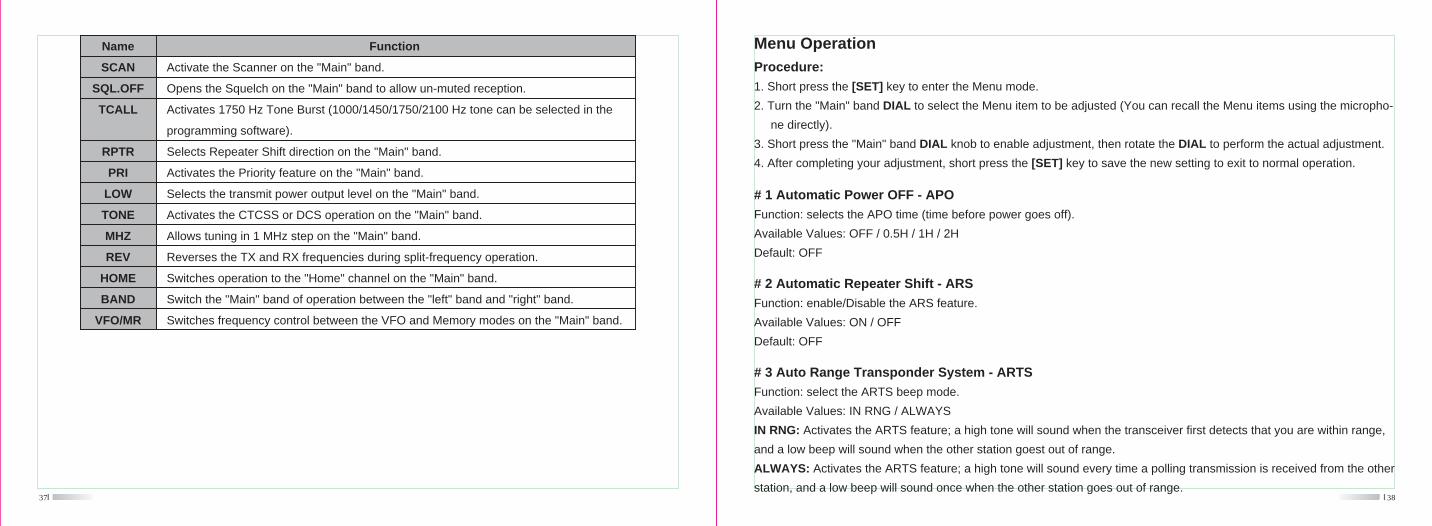
Activate the Scanner on the "Main" band.
Opens the Squelch on the "Main" band to allow un-muted reception.
Activates 1750 Hz Tone Burst (1000/1450/1750/2100 Hz tone can be selected in the
programming software).
Selects Repeater Shift direction on the "Main" band.
Activates the Priority feature on the "Main" band.
Selects the transmit power output level on the "Main" band.
Activates the CTCSS or DCS operation on the "Main" band.
Allows tuning in 1 MHz step on the "Main" band.
Reverses the TX and RX frequencies during split-frequency operation.
Switches operation to the "Home" channel on the "Main" band.
Switch the "Main" band of operation between the "left" band and "right" band.
Switches frequency control between the VFO and Memory modes on the "Main" band.
Name
SCAN
SQL.OFF
TCALL
RPTR
PRI
LOW
TONE
MHZ
REV
HOME
BAND
VFO/MR
Function
# 9 DSP.MOD
Function: select Memory channel display mode.
Available Values: DSP.FRQ / DSP.NAM
Default: DSP.FRQ
40
# 10 DTMF D
Function: setting of the DTMF autodialer delay time.
Available Values: 50 / 250 / 450 / 750 / 1000 MS.
Default: 450 MS.
# 11 DTMF S
Function: setting of the DTMF autodialer sending speed.
Available Values: 50 / 75 / 100 MS.
Default: 50 MS.
# 12 DTMF W
Function: loading of the DTMF autodialer memories.
16 DTMF autodialer memories are available.
# 13 HYPER
Function: enable/disable the automatic writing feature for the Hyper Memory.
Available Values: MANUAL / AUTO
Default: MANUAL
# 14 KEY.MOD
Function: select the key functions for the "right" band function switches.39
# 4 BEEP
Function: enable/Disable the beeper
Available Values: BEP.ON / BEP.OFF
Default: BEP.ON
# 5 Clock frequency shift - CLK.SFT
Function: shifting of CPU clock frequency
Available Values: SFT.ON / SFT.OFF
Default: SFT.OFF
# 6 DIMMER
Function: setting of the display brightness level.
Available Values: DIM. OFF / 1 / 2 / 3 / 4
Default: DIM 3
# 7 DCS.COD
Function: setting the DCS code.
Available Values: 104 standard DCS codes.
Default: 023
# 8 DCS.N/R
Function: select "Normal" or "Inverted" DCS coding.
Available Values: TRX N / TX R / RX R / TRX R
Default: TRX N
42
# 24 RPT.MOD
Function: set the repeater shift direction.
Available Values: RPT.OFF / RPT.- / RPT.+
Default: RPT.OFF
Note: The repeater shift can be set independently on both the "left" and "right" bands.
Default: BAND
# 20 PG P2
Function: program the microphone's [p2] button assignment.
Default: VFO/MR
# 21 PG P3
Function: program the microphone's [p3] button assignment.
Default: TONE
# 22 PG P4
Function: program the microphone's [p4] button assignment.
Default: LOW
# 23 RF SQL
Function: Adjustd the RF SQL threshold level.
Available Values: OFF / S-2 / S-5 / S-9 / S-FULL
Default: OFF
Note: The Menu Item can be set independently on both the "left" and "right" bands.
# 15 LOCK
Function: enable/disable the Key/Button Lock feature.
Available Values: MANUAL / AUTO
Default: MANUAL
41
Available Values: KEY1 / KEY2
Default: KEY1
# 16 LOCKT
Function: enable/disable the PTT lock feature.
Available Values: OFF / BAND R / BAND L / BOTH
Default: OFF
OFF: Enable the PTT switch.
BAND R: Disable the PTT switch on the "right" band.
BAND L: Disable the PTT switch on the "left" band.
BOTH: Disable the PTT switch on the "both" band.
# 17 MUTE
Function: select the audio mute mode.
Available Values: OFF / TX / RX and TX/RX
# 18 NAME
Function: store an alpha tag for a memory channel.
# 19 PG P1
Function: program the microphone's [P1] button assignment.
44
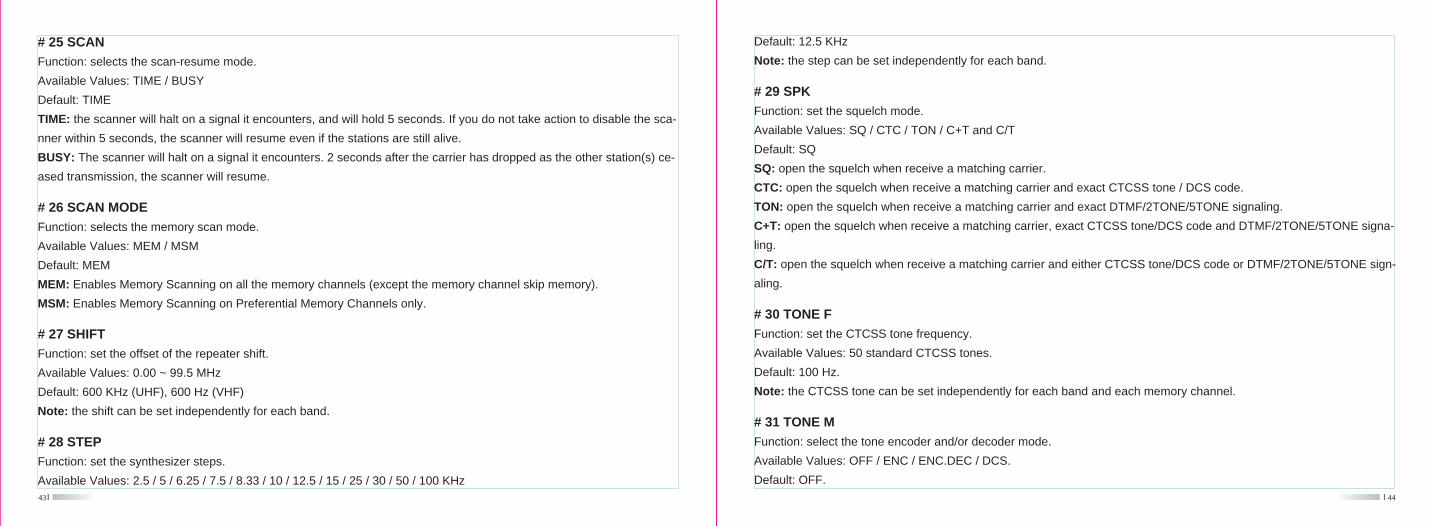
# 29 SPK
Function: set the squelch mode.
Available Values: SQ / CTC / TON / C+T and C/T
Default: SQ
SQ: open the squelch when receive a matching carrier.
CTC: open the squelch when receive a matching carrier and exact CTCSS tone / DCS code.
TON: open the squelch when receive a matching carrier and exact DTMF/2TONE/5TONE signaling.
C+T: open the squelch when receive a matching carrier, exact CTCSS tone/DCS code and DTMF/2TONE/5TONE signa-
ling.
C/T: open the squelch when receive a matching carrier and either CTCSS tone/DCS code or DTMF/2TONE/5TONE sign-
aling.
Default: 12.5 KHz
Note: the step can be set independently for each band.
# 30 TONE F
Function: set the CTCSS tone frequency.
Available Values: 50 standard CTCSS tones.
Default: 100 Hz.
Note: the CTCSS tone can be set independently for each band and each memory channel.
# 31 TONE M
Function: select the tone encoder and/or decoder mode.
Available Values: OFF / ENC / ENC.DEC / DCS.
Default: OFF.43
# 25 SCAN
Function: selects the scan-resume mode.
Available Values: TIME / BUSY
Default: TIME
TIME: the scanner will halt on a signal it encounters, and will hold 5 seconds. If you do not take action to disable the sca-
nner within 5 seconds, the scanner will resume even if the stations are still alive.
BUSY: The scanner will halt on a signal it encounters. 2 seconds after the carrier has dropped as the other station(s) ce-
ased transmission, the scanner will resume.
# 26 SCAN MODE
Function: selects the memory scan mode.
Available Values: MEM / MSM
Default: MEM
MEM: Enables Memory Scanning on all the memory channels (except the memory channel skip memory).
MSM: Enables Memory Scanning on Preferential Memory Channels only.
# 27 SHIFT
Function: set the offset of the repeater shift.
Available Values: 0.00 ~ 99.5 MHz
Default: 600 KHz (UHF), 600 Hz (VHF)
Note: the shift can be set independently for each band.
# 28 STEP
Function: set the synthesizer steps.
Available Values: 2.5 / 5 / 6.25 / 7.5 / 8.33 / 10 / 12.5 / 15 / 25 / 30 / 50 / 100 KHz
46
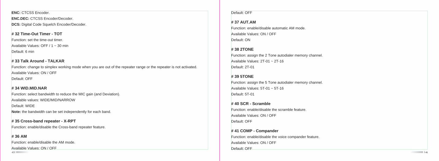
# 37 AUT.AM
Function: enable/disable automatic AM mode.
Available Values: ON / OFF
Default: ON
Default: OFF
# 38 2TONE
Function: assign the 2 Tone autodialer memory channel.
Available Values: 2T-01 ~ 2T-16
Default: 2T-01
# 39 5TONE
Function: assign the 5 Tone autodialer memory channel.
Available Values: 5T-01 ~ 5T-16
Default: 5T-01
# 40 SCR - Scramble
Function: enable/disable the scramble feature.
Available Values: ON / OFF
Default: OFF
# 41 COMP - Compander
Function: enable/disable the voice compander feature.
Available Values: ON / OFF
Default: OFF45
# 32 Time-Out Timer - TOT
Function: set the time-out timer.
Available Values: OFF / 1 ~ 30 min
Default: 6 min
ENC: CTCSS Encoder.
ENC.DEC: CTCSS Encoder/Decoder.
DCS: Digital Code Squelch Encoder/Decoder.
# 33 Talk Around - TALKAR
Function: change to simplex working mode when you are out of the repeater range or the repeater is not activated.
Available Values: ON / OFF
Default: OFF
# 34 WID.MID.NAR
Function: select bandwidth to reduce the MIC gain (and Deviation).
Available values: WIDE/MID/NARROW
Default: WIDE
Note: the bandwidth can be set independently for each band.
# 35 Cross-band repeater - X-RPT
Function: enable/disable the Cross-band repeater feature.
# 36 AM
Function: enable/disable the AM mode.
Available Values: ON / OFF
48
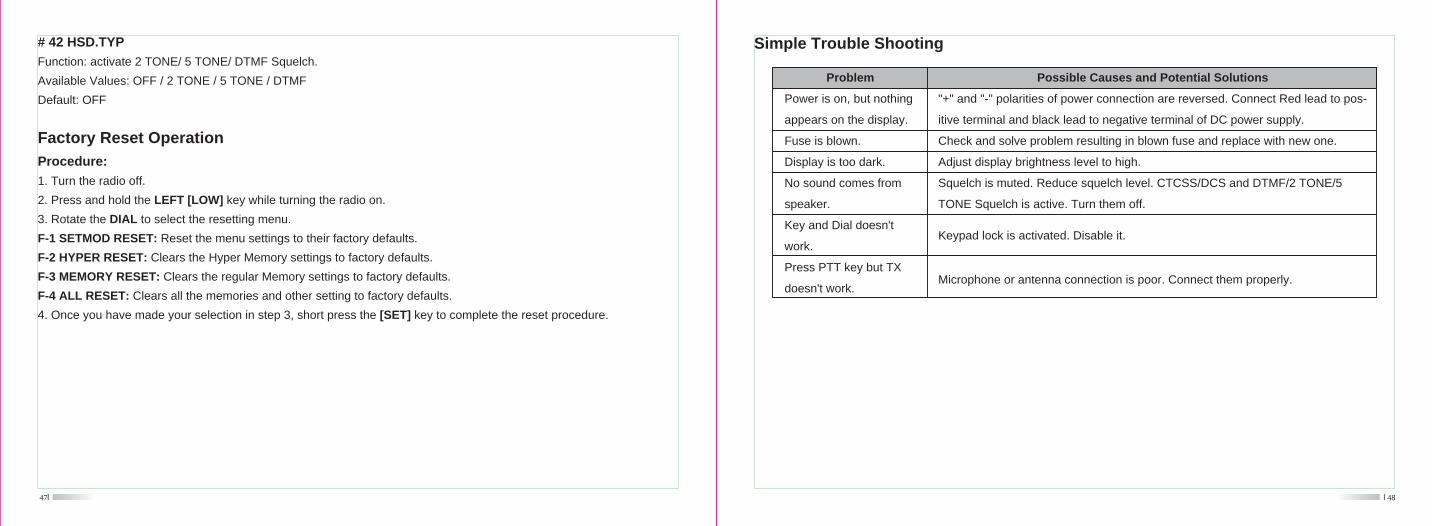
Simple Trouble Shooting
"+" and "-" polarities of power connection are reversed. Connect Red lead to pos-
itive terminal and black lead to negative terminal of DC power supply.
Check and solve problem resulting in blown fuse and replace with new one.
Adjust display brightness level to high.
Squelch is muted. Reduce squelch level. CTCSS/DCS and DTMF/2 TONE/5
TONE Squelch is active. Turn them off.
Power is on, but nothing
appears on the display.
Fuse is blown.
Display is too dark.
No sound comes from
speaker.
Key and Dial doesn't
work.
Press PTT key but TX
doesn't work.
Problem Possible Causes and Potential Solutions
Microphone or antenna connection is poor. Connect them properly.
Keypad lock is activated. Disable it.
47
Factory Reset Operation
Procedure:
1. Turn the radio off.
2. Press and hold the LEFT [LOW] key while turning the radio on.
3. Rotate the DIAL to select the resetting menu.
F-1 SETMOD RESET: Reset the menu settings to their factory defaults.
F-2 HYPER RESET: Clears the Hyper Memory settings to factory defaults.
F-3 MEMORY RESET: Clears the regular Memory settings to factory defaults.
F-4 ALL RESET: Clears all the memories and other setting to factory defaults.
4. Once you have made your selection in step 3, short press the [SET] key to complete the reset procedure.
# 42 HSD.TYP
Function: activate 2 TONE/ 5 TONE/ DTMF Squelch.
Available Values: OFF / 2 TONE / 5 TONE / DTMF
Default: OFF