the 2019 audi a8 running gear and suspension systems · air suspension with dynamic control is...
TRANSCRIPT
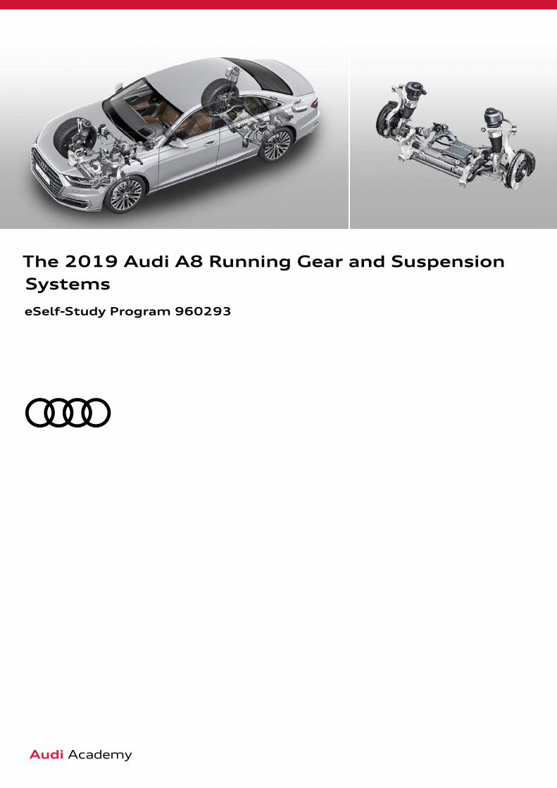
The 2019 Audi A8 Running Gear and Suspension Systems
eSelf-Study Program 960293
ii
Audi of America, LLC Service Training Created in the U.S.A. Created 5/2018 Course Number 960293
©2018 Audi of America, LLC
All rights reserved. Information contained in this manual is based on the latest information available at the time of printing and is subject to the copyright and other intellectual property rights of Audi of America, LLC., its affiliated companies and its licensors. All rights are reserved to make changes at any time without notice. No part of this document may be reproduced, stored in a retrieval system, or transmitted in any form or by any means, electronic, mechanical, photocopying, recording or otherwise, nor may these materials be modified or reposted to other sites without the prior expressed written permission of the publisher.All requests for permission to copy and redistribute information should be referred to Audi of America, LLC.
Always check Technical Bulletins and the latest electronic service repair literature for information that may supersede any information included in this booklet.
Revision: May 29, 2018

iii
Note
Reference
Introduction 1
Axles 2Front axle 2Rear axle 3Wheel alignment and adjustment 4
Steering system 5Overview 5System components 5
Dynamic all-wheel steering 6Overview 6Basic function 9Programs for particular driving situations 11Operation and warning/indicator lamps 12System response to faults 12Service 13
Brake system 14Brake system, front axle 14Brake system, rear axle 14Brake servo 15Electromechanical parking brake (EPB) 15ESC 16
Adaptive air suspension 18Overview 18Air supply 19Air spring strut, front axle 20Air spring strut, rear axle 20Accumulator 20Vehicle level sensors 20System response to faults 22Service 22
Knowledge assessment 23
The eSelf-Study Program (eSSP) teaches a basic understanding of the design and mode of operation of new models, new automotive components or new technologies. It is not a repair manual! Figures are given for explanatory purposes only and refer to the data valid at the time of preparation of the SSP.
For further information about maintenance and repair work, always refer to the current technical literature.

iv
1
663_001
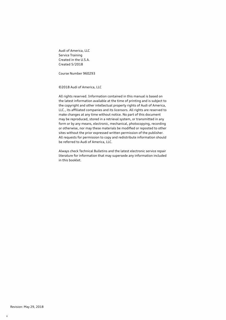
The suspension of the 2019 A8 has been designed with new technologies and control systems to achieve even greater levels of comfort, driving dynamics and safety. Air suspension with dynamic control is standard. The front and rear axles of each consist of a responsive high precision five-link construc-tion made in large part out of aluminum.
Progressive steering (included as standard equipment) reduces the amount of steering effort required. Optional dynamic steering is combined with rear wheel steering for the first time for Audi in the 2019 A8. This system enhances certain essential subjective and objective dynamic characteris-tics of the driving experience.
All Audi A8 vehicles are equipped exclusively with running gear versions with quattro four-wheel drive. The following suspension version is available:
› Air suspension and damping control (adaptive air suspension, 1BK) This version is standard equipment.
The brake system offers substantial performance reserves for any driving situation.
A ceramic brake system is available as optional equipment. The 9th generation ESC system provides high-performance stability control for the vehicle.
A wide range of steering wheels, wheels and tires is available for further customization. With the Audi A8, ACC is included for the first time in the new driver assist system “adaptive cruise assist”.
Introduction

2
663_002
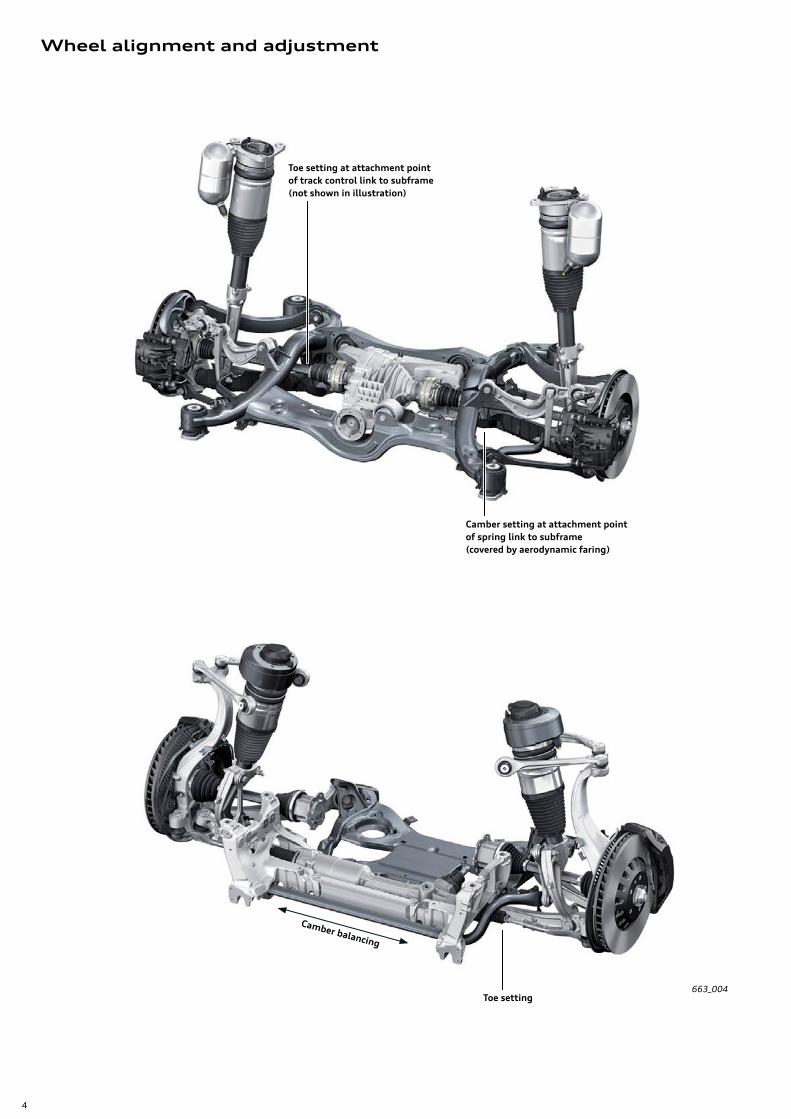
Front axle
The front axle is constructed according to the well-estab-lished five-link axle design, with particular emphasis on light-weight construction. All fundamental components are constructed from aluminum.
Upper wishbone › Forged aluminum components › Adopted from the 2018 Q5
Wheel bearing housing › Forged aluminum components › New design
Air spring/damper › Forged aluminum component › New part
Swivel joint › Adopted from
2017 Audi Q7 › Aluminum housing
Shock absorber fork › Aluminum component
(cast-forged) › Adopted from
2017 Audi Q7
Anti-roll bar link rod › Aluminum component › Adopted from
2017 Audi Q7
Anti-roll bar › Thin-walled tubular anti-roll bar › New part › Aluminum anti-roll bar
clamps, adopted from 2017 Audi Q7
Subframe › Three-part aluminum construction comprising a
cross member (extrusion) and two node castings
Track control links and guide links › Forged aluminum components › Adopted from
2017 Audi Q7
Wheel bearing/wheel hub › Second generation wheel
bearing › Adopted from
2017 Audi A4/2018 Q5
Axles

3
663_003
Rear axle
The rear suspension of the 2019 A8 is a newly developed five-link axle.
The geometric layout of the suspension links provides a clear separation in the absorption of longitudinal and lateral forces. Elastomer bushings with a mixture of high-damping materials and integrated spacer sleeves allow for a high degree of radial stiffness with a low roll rate.
The use of subframe bushings with hydraulic damping ensures that the axle is well-isolated from the vehicle body. The wheel bearings have been optimized to reduce friction, which helps to decrease rolling resistance.
Rear wheel steering is available as part of the optional all-wheel steering.
Air spring/damper › Forged aluminum component › New part
Track rod › Forged aluminum component › New part
Upper wishbone (rear) › Steel/forged aluminum component › New part/adopted from 2017 Q7
Upper wishbone (front) › Forged aluminum
component › New part
Lower wishbone (rear) › Aluminum › New part
Wheel bearing/wheel hub › 3rd generation › New part
Lower wishbone (front) › Sheet-steel part › New part
Anti-roll bar › Forged aluminum component › New part
Hub carrier › Forged aluminum
component › New part
Coupling rod › Forged aluminum component › New part
Subframe › Aluminum › New part
4
663_004
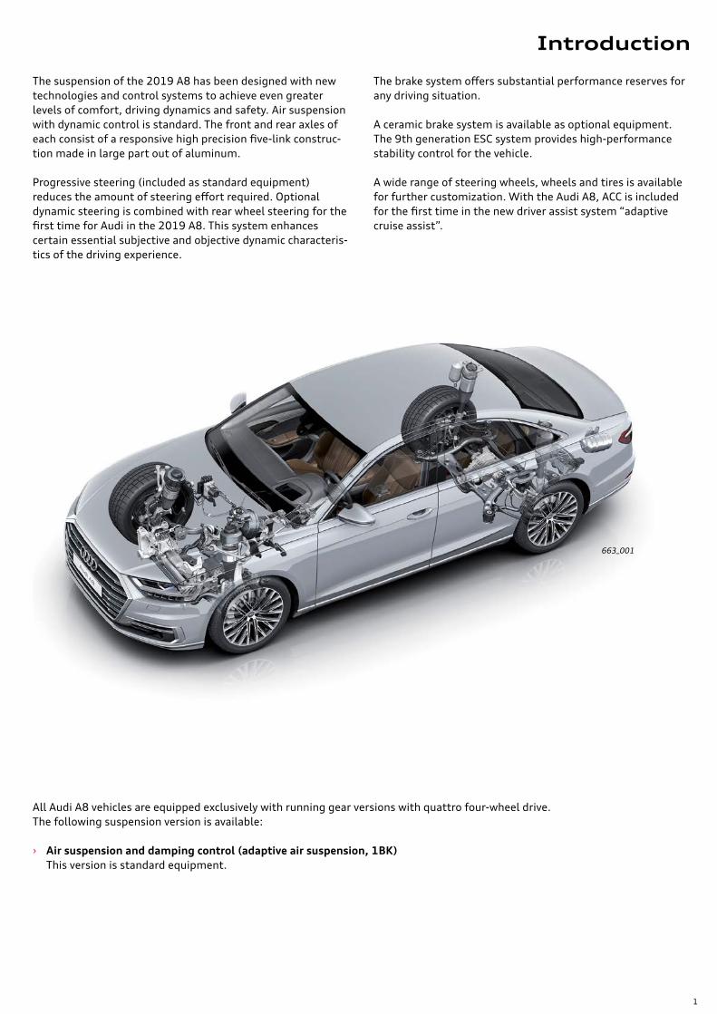
Wheel alignment and adjustment
Toe setting at attachment pointof track control link to subframe(not shown in illustration)
Camber setting at attachment pointof spring link to subframe(covered by aerodynamic faring)
Toe setting
Camber balancing

5
663_005
663_006
663_007
663_008
Overview
System components
The steering system of the 2019 A8 is the same electrome-chanical power steering used in the 2017 Q7. Electrical steering column adjustment is standard equipment.
The optional dynamic all-wheel steering system includes rear wheel steering.
Electromechanical power steering
The electrical power steering (EPS) system of the A8 has the same layout and functionality as the system used in the 2017 Q7. The service procedures are the also the same. Power Steering Control Module J500 communicates via FlexRay channel A.
Progressive steering is included as standard equipment.
Steering wheels
The available steering wheels have a four-spoke design and a total diameter of 14.7 in (375 mm). The standard equip-ment version has a plastic airbag cover. Multifunction switches are installed on all steering wheel versions. All of the steering wheels offered as optional equipment feature aluminum tiptronic levers. Steering wheel heating and different steering wheel colors are available as optional extras.
Steering column
All A8 models are equipped with an electrically adjustable steering column. It can be adjusted approximately 2.3 in (60 mm) horizontally and 1.9 in (50 mm) vertically. Power Steering Control Module J500 and both adjustment motors are attached directly to the steering column.
In the event of a crash, the column moves relative to the column tube. This is possible because of the nested tube construction. The maximum distance of travel is approxi-mately 3.1 in (80 mm).
On vehicles with dynamic all-wheel steering, the steering column is shorter because the actuator for the dynamic steering is attached at the bottom end of the steering column.
Steering system
6
663_010
663_011
663_009
Overview
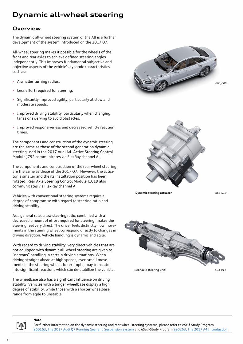
The dynamic all-wheel steering system of the A8 is a further development of the system introduced on the 2017 Q7.
All-wheel steering makes it possible for the wheels of the front and rear axles to achieve defined steering angles independently. This improves fundamental subjective and objective aspects of the vehicle’s dynamic characteristics such as:
› A smaller turning radius.
› Less effort required for steering.
› Significantly improved agility, particularly at slow and moderate speeds.
› Improved driving stability, particularly when changing lanes or swerving to avoid obstacles.
› Improved responsiveness and decreased vehicle reaction times.
The components and construction of the dynamic steering are the same as those of the second generation dynamic steering used in the 2017 Audi A4. Active Steering Control Module J792 communicates via FlexRay channel A.
The components and construction of the rear wheel steering are the same as those of the 2017 Q7. However, the actua-tor is smaller and the its installation position has been rotated. Rear Axle Steering Control Module J1019 also communicates via FlexRay channel A.
Vehicles with conventional steering systems require a degree of compromise with regard to steering ratio and driving stability.
As a general rule, a low steering ratio, combined with a decreased amount of effort required for steering, makes the steering feel very direct. The driver feels distinctly how move-ments in the steering wheel correspond directly to changes in driving direction. Vehicle handling is dynamic and agile.
With regard to driving stability, very direct vehicles that are not equipped with dynamic all-wheel steering are given to “nervous” handling in certain driving situations. When driving straight ahead at high speeds, even small move-ments in the steering wheel, for example, may translate into significant reactions which can de-stabilize the vehicle. The wheelbase also has a significant influence on driving stability. Vehicles with a longer wheelbase display a high degree of stability, while those with a shorter wheelbase range from agile to unstable.
Dynamic steering actuator
Rear axle steering unit
NoteFor further information on the dynamic steering and rear wheel steering systems, please refer to eSelf-Study Program 960163, The 2017 Audi Q7 Running Gear and Suspension System and eSelf-Study Program 990263, The 2017 A4 Introduction.
Dynamic all-wheel steering
7
663_012
663_013
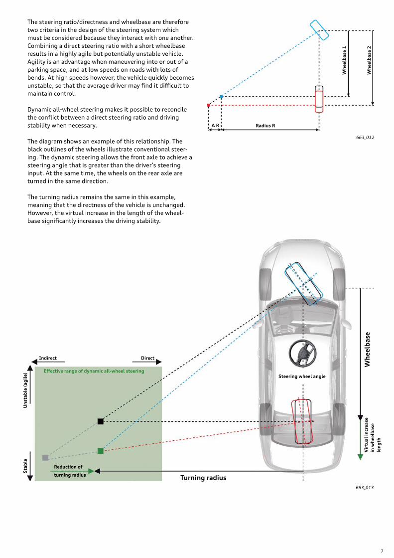
The steering ratio/directness and wheelbase are therefore two criteria in the design of the steering system which must be considered because they interact with one another. Combining a direct steering ratio with a short wheelbase results in a highly agile but potentially unstable vehicle. Agility is an advantage when maneuvering into or out of a parking space, and at low speeds on roads with lots of bends. At high speeds however, the vehicle quickly becomes unstable, so that the average driver may find it difficult to maintain control.
Dynamic all-wheel steering makes it possible to reconcile the conflict between a direct steering ratio and driving stability when necessary.
The diagram shows an example of this relationship. The black outlines of the wheels illustrate conventional steer-ing. The dynamic steering allows the front axle to achieve a steering angle that is greater than the driver’s steering input. At the same time, the wheels on the rear axle are turned in the same direction.
The turning radius remains the same in this example, meaning that the directness of the vehicle is unchanged. However, the virtual increase in the length of the wheel-base significantly increases the driving stability.
DirectIndirect
Steering wheel angle
Reduction of
Radius RΔ R
Vir
tual
incr
ease
in
wh
eelb
ase
len
gth
Wh
eelb
ase
1
Wh
eelb
ase
2
Sta
ble
Un
stab
le (
agil
e)
Effective range of dynamic all-wheel steering
turning radius Turning radius
Wh
eelb
ase

8
663_014
With dynamic all-wheel steering, the required steering angle at the front and rear axles is specified by Drivetrain Control Module J775. The specified steering angle is con-verted into the actual electrical current requirements for the actuators at the front and rear axles by Power Steering Control Module J500, Rear Axle Steering Control Module J1019, and Active Steering Control Module J792.
These control modules transmit data via FlexRay channel A. Dynamic steering and rear wheel steering are not offered separately for the Audi A8, but only as part of the dynamic all-wheel steering package.
Electromechanical power steering withPower Steering Control Module J500
Dynamic steering actuator Drivetrain Control ModuleJ775
Rear Axle Steering Control Module J1019
Active Steering Control Module J792
9
663_015
Basic function
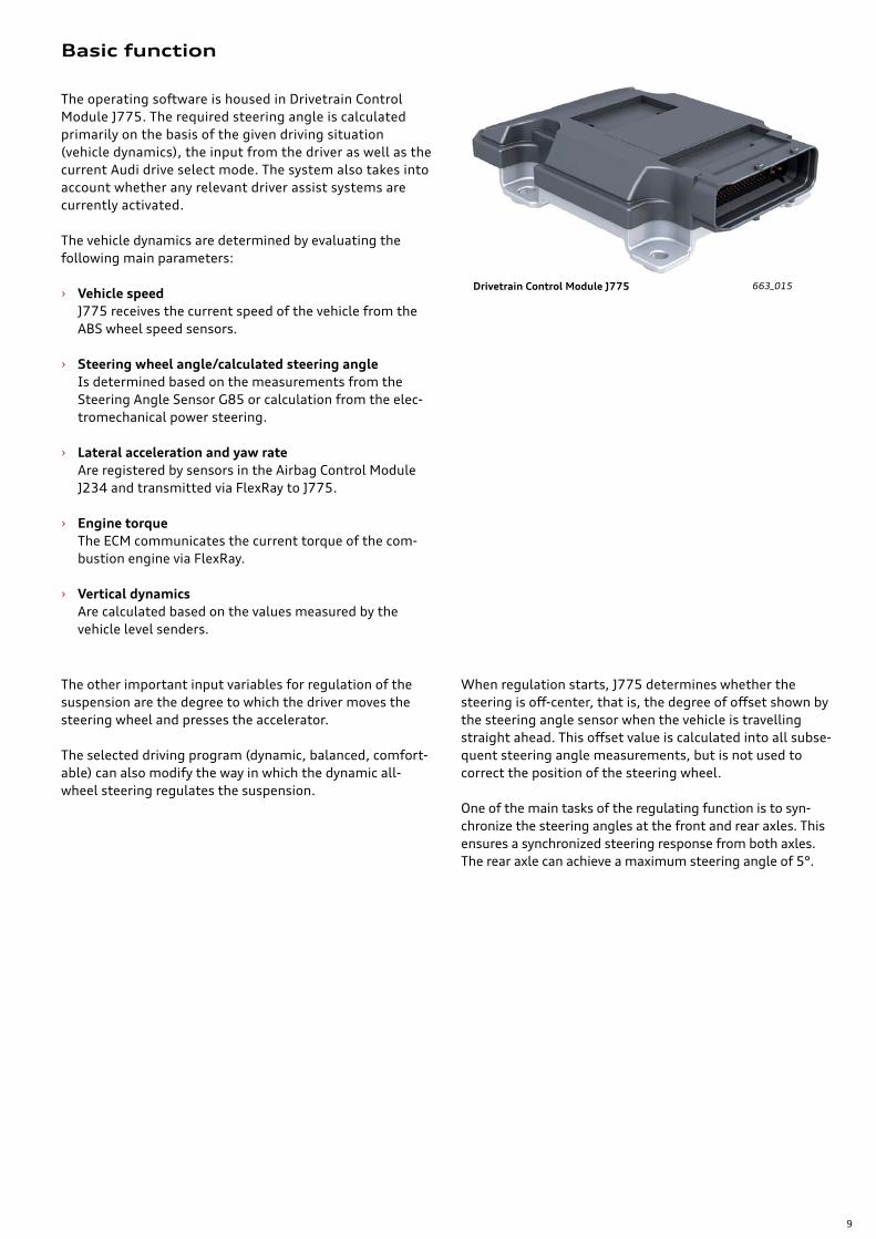
The operating software is housed in Drivetrain Control Module J775. The required steering angle is calculated primarily on the basis of the given driving situation (vehicle dynamics), the input from the driver as well as the current Audi drive select mode. The system also takes into account whether any relevant driver assist systems are currently activated.
The vehicle dynamics are determined by evaluating the following main parameters:
› Vehicle speed J775 receives the current speed of the vehicle from the ABS wheel speed sensors.
› Steering wheel angle/calculated steering angle Is determined based on the measurements from the Steering Angle Sensor G85 or calculation from the elec-tromechanical power steering.
› Lateral acceleration and yaw rate Are registered by sensors in the Airbag Control Module J234 and transmitted via FlexRay to J775.
› Engine torque The ECM communicates the current torque of the com-bustion engine via FlexRay.
› Vertical dynamics Are calculated based on the values measured by the vehicle level senders.
Drivetrain Control Module J775
The other important input variables for regulation of the suspension are the degree to which the driver moves the steering wheel and presses the accelerator.
The selected driving program (dynamic, balanced, comfort-able) can also modify the way in which the dynamic all-wheel steering regulates the suspension.
When regulation starts, J775 determines whether the steering is off-center, that is, the degree of offset shown by the steering angle sensor when the vehicle is travelling straight ahead. This offset value is calculated into all subse-quent steering angle measurements, but is not used to correct the position of the steering wheel.
One of the main tasks of the regulating function is to syn-chronize the steering angles at the front and rear axles. This ensures a synchronized steering response from both axles. The rear axle can achieve a maximum steering angle of 5°.
Rear Axle Steering Control Module J1019

10
663_016
The diagram shows the primary input and output informa-tion, along with the control modules active in the steering regulation process.
J775 includes the regulating software for various systems which also exchange information amongst themselves. This means that the regulating software for the dynamic all-wheel steering also receives information about the vehicle level from the adaptive air suspension.
Steering Angle SensorG85
Drivetrain Control ModuleJ775
Steering wheel angle
Wheel rotations
Drive Select setting
Lateral accele-ration/yaw rate
Status
Actual steering angle
Required steering angle
Status of driver assist systems
Actual engine torque accelerator position
Power Steering Control Module J500
Active Steering Control ModuleJ792 (dynamic steering)
Rear Axle Steering Control Module (all-wheel steering) J1019
ABS Control ModuleJ104
Data Bus on Board Diagnostic InterfaceJ533
Airbag Control ModuleJ234
Driver Assistance Systems Control ModuleJ1121
Engine Control ModuleJ623
11
663_017
24.8 (40)
37.2 (60)
47.9(80)
62.1(100)
74.5(120)
89.9(140)
99.4(160)
111.8(180)
124.2(200)
136.7 (220)
149.1 (240)
When the ignition is switched on (Terminal 15 on), plausi-bility check routines are performed.
If the driver turns the steering wheel after the engine is started but while the vehicle is still stationary, the rear wheels can turn up to 0.5° in the opposite direction.
When the vehicle drives off, the required steering angle of the rear wheels is calculated, factoring in a virtual curb. The rear wheels then turn only so far as to allow the vehicle to drive off without contacting the curb.
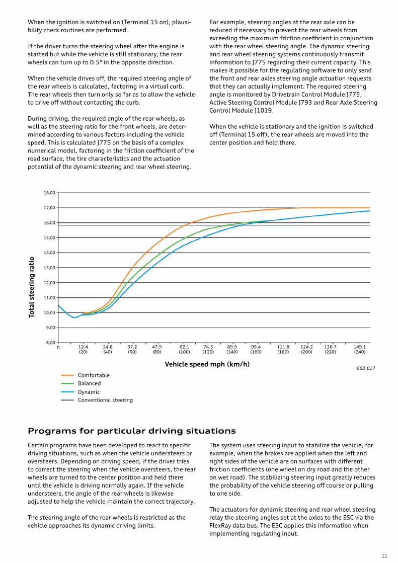
During driving, the required angle of the rear wheels, as well as the steering ratio for the front wheels, are deter-mined according to various factors including the vehicle speed. This is calculated J775 on the basis of a complex numerical model, factoring in the friction coefficient of the road surface, the tire characteristics and the actuation potential of the dynamic steering and rear wheel steering.
For example, steering angles at the rear axle can be reduced if necessary to prevent the rear wheels from exceeding the maximum friction coefficient in conjunction with the rear wheel steering angle. The dynamic steering and rear wheel steering systems continuously transmit information to J775 regarding their current capacity. This makes it possible for the regulating software to only send the front and rear axles steering angle actuation requests that they can actually implement. The required steering angle is monitored by Drivetrain Control Module J775, Active Steering Control Module J793 and Rear Axle Steering Control Module J1019.
When the vehicle is stationary and the ignition is switched off (Terminal 15 off), the rear wheels are moved into the center position and held there.
Certain programs have been developed to react to specific driving situations, such as when the vehicle understeers or oversteers. Depending on driving speed, if the driver tries to correct the steering when the vehicle oversteers, the rear wheels are turned to the center position and held there until the vehicle is driving normally again. If the vehicle understeers, the angle of the rear wheels is likewise adjusted to help the vehicle maintain the correct trajectory.
The steering angle of the rear wheels is restricted as the vehicle approaches its dynamic driving limits.
The system uses steering input to stabilize the vehicle, for example, when the brakes are applied when the left and right sides of the vehicle are on surfaces with different friction coefficients (one wheel on dry road and the other on wet road). The stabilizing steering input greatly reduces the probability of the vehicle steering off course or pulling to one side.
The actuators for dynamic steering and rear wheel steering relay the steering angles set at the axles to the ESC via the FlexRay data bus. The ESC applies this information when implementing regulating input.
Programs for particular driving situations
Tota
l ste
erin
g r
atio
Vehicle speed mph (km/h)
ComfortableBalanced
DynamicConventional steering
12.4 (20)

12
663_018
Operation and warning/indicator lamps
System response to faults
The driver can change the setup of the steering system using Audi drive select. There are three different character-istic maps available for the steering system: comfortable, balanced and dynamic.
When an individual mode is activated, the driver can select from the three setups as desired. The warning/indicator lamps regarding the steering system are only displayed in event of a fault.
The systems and components associated with the dynamic all-wheel steering are capable of self-diagnosis. Drivetrain Control Module J775 receives continuous feedback regard-ing the availability and status of the EPS, dynamic steering and rear wheel steering.
System:Malfunction/fault
System responseWarning/indi-cator lamp
Text on center display
EPS:1. Steering wheel angles not
adapted or certain input signals implausible
1. Power steering level ≤ 61% until source of fault is eliminated Yellow
-
2. Certain faults occurring during a terminal 15 cycle
2. Power steering level ≤ 61% until Terminal 15 is switched off
YellowSteering: fault.You can continue driving
3. Faults that can eventually lead to critical situations
3. Power steering level = 20%, main-tained for approximately 1 minute to give the driver the chance to bring the vehicle to a halt, the rear wheel steering is brought into the center position and deactivated.
RedSteering: fault.Please stop vehicle.
Dynamic steering: all types
Variable steering ratio no longer available (backup program: fixed ratio) Rear wheels are brought into the center position and the rear wheel steering is deactivated.
YellowSteering: fault.Adapt driving style.Turning circle larger
Rear wheel steering:1. Some functions still avail-
able, wheels can still be turned
1. Rear wheels are brought into the center position and the rear wheel steering is deactivated.
YellowSteering: fault.Adapt driving style.Turning circle larger
2. Complete system failure, wheels can no longer be turned
Rear wheels remain as positioned: › If the wheels were not positioned straight ahead, this will result in “crabbing” on one side of the vehicle and a reduced turning radius on the other side.
RedSteering: fault.Please stop vehicle.Note distance to side
Depending on the severity of a given malfunction, a backup program will be activated accordingly. At the same time, the system will maintain full functionality for as long as possible.
The following table lists the main faults and the warning/indicator lamps and messages that the driver sees:
≤ equal to or greater than

13
Service
Control modules associated with the system:
› Drivetrain Control Module J775 Address Word 0074 › Active Steering Control Module J792 Address Word 001B › Power Steering Control Module J500 Address Word 0044 › Rear Axle Steering Control Module J1019 Address Word 00CB
The service operations are the same as for the electrome-chanical power steering and rear wheel steering on the 2017 Q7 and the dynamic steering of the 2017 A4.
The basic setting/calibration procedure for Drivetrain Control Module J775 is the same as on the 2017 Q7. Keep in mind that the basic setting procedure may need to be performed for additional vehicle systems depending on the vehicle equipment.
For further information, please refer to the Workshop Manual.

14
663_019 663_020
663_021 663_022
The Audi A8 is equipped with a brake system with substantial performance reserves. As with the current Q7, Q5 and A4 models, the brakes on the front and rear axles of the Audi A8 have separate brake circuits.
The brake calipers are also available in black.
Brake system, front axle
Brake system, rear axle
Front brakes, conventional
Rear brakes, conventional
Front brakes, ceramic
Rear brakes, ceramic
Engine 3.0 ltr. TFSIOptionalceramic brakes
Minimum wheel size 18" 20"
Type of brakesAKE fixed caliper brakes(30-36-38)
AKE fixed caliper brakes(4x27-6x28.5mm)
Number of pistons 6 10
Brake disc diameter 14.7 in (375 mm) 16.5 in (420 mm)
Brake disc thickness 1.4 in (36 mm) 1.5 in (40 mm)
Engine 3.0 ltr. TFSIOptionalceramic brakes
Minimum wheel size 18" 19"
Type of brakes TRW EPBi 44 TRW EPBi 44 CSiC
Number of pistons 1 1
Brake disc diameter 9.8 in (350 mm) 14.5 in (370 mm)
Brake disc thickness 1.1 in (28 mm) 1.1 in (30 mm)
Brake system
15
663_023
663_024
663_025
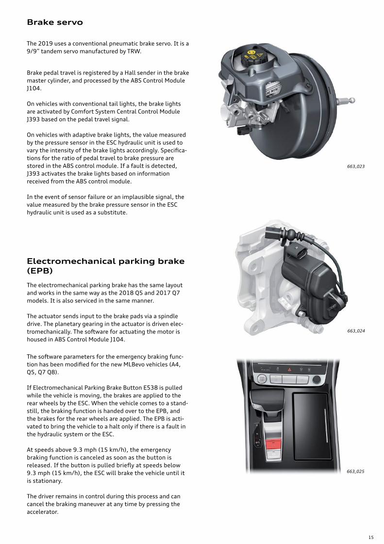
Brake servo
The 2019 uses a conventional pneumatic brake servo. It is a 9/9” tandem servo manufactured by TRW.
Brake pedal travel is registered by a Hall sender in the brake master cylinder, and processed by the ABS Control Module J104.
On vehicles with conventional tail lights, the brake lights are activated by Comfort System Central Control Module J393 based on the pedal travel signal.
On vehicles with adaptive brake lights, the value measured by the pressure sensor in the ESC hydraulic unit is used to vary the intensity of the brake lights accordingly. Specifica-tions for the ratio of pedal travel to brake pressure are stored in the ABS control module. If a fault is detected, J393 activates the brake lights based on information received from the ABS control module.
In the event of sensor failure or an implausible signal, the value measured by the brake pressure sensor in the ESC hydraulic unit is used as a substitute.
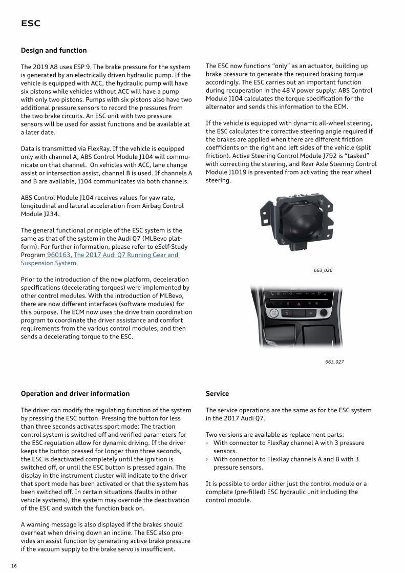
Electromechanical parking brake (EPB)
The electromechanical parking brake has the same layout and works in the same way as the 2018 Q5 and 2017 Q7 models. It is also serviced in the same manner.
The actuator sends input to the brake pads via a spindle drive. The planetary gearing in the actuator is driven elec-tromechanically. The software for actuating the motor is housed in ABS Control Module J104.
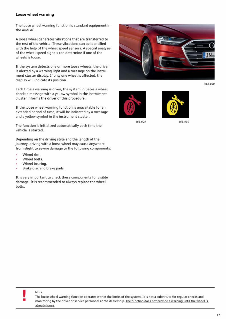
The software parameters for the emergency braking func-tion has been modified for the new MLBevo vehicles (A4, Q5, Q7 Q8).
If Electromechanical Parking Brake Button E538 is pulled while the vehicle is moving, the brakes are applied to the rear wheels by the ESC. When the vehicle comes to a stand-still, the braking function is handed over to the EPB, and the brakes for the rear wheels are applied. The EPB is acti-vated to bring the vehicle to a halt only if there is a fault in the hydraulic system or the ESC.
At speeds above 9.3 mph (15 km/h), the emergency braking function is canceled as soon as the button is released. If the button is pulled briefly at speeds below 9.3 mph (15 km/h), the ESC will brake the vehicle until it is stationary.
The driver remains in control during this process and can cancel the braking maneuver at any time by pressing the accelerator.
16
663_026
663_027
ESC
Design and function
The 2019 A8 uses ESP 9. The brake pressure for the system is generated by an electrically driven hydraulic pump. If the vehicle is equipped with ACC, the hydraulic pump will have six pistons while vehicles without ACC will have a pump with only two pistons. Pumps with six pistons also have two additional pressure sensors to record the pressures from the two brake circuits. An ESC unit with two pressure sensors will be used for assist functions and be available at a later date.
Data is transmitted via FlexRay. If the vehicle is equipped only with channel A, ABS Control Module J104 will commu-nicate on that channel. On vehicles with ACC, lane change assist or intersection assist, channel B is used. If channels A and B are available, J104 communicates via both channels.
ABS Control Module J104 receives values for yaw rate, longitudinal and lateral acceleration from Airbag Control Module J234.
The general functional principle of the ESC system is the same as that of the system in the Audi Q7 (MLBevo plat-form). For further information, please refer to eSelf-Study Program 960163, The 2017 Audi Q7 Running Gear and Suspension System.
Prior to the introduction of the new platform, deceleration specifications (decelerating torques) were implemented by other control modules. With the introduction of MLBevo, there are now different interfaces (software modules) for this purpose. The ECM now uses the drive train coordination program to coordinate the driver assistance and comfort requirements from the various control modules, and then sends a decelerating torque to the ESC.
Operation and driver information
The driver can modify the regulating function of the system by pressing the ESC button. Pressing the button for less than three seconds activates sport mode: The traction control system is switched off and verified parameters for the ESC regulation allow for dynamic driving. If the driver keeps the button pressed for longer than three seconds, the ESC is deactivated completely until the ignition is switched off, or until the ESC button is pressed again. The display in the instrument cluster will indicate to the driver that sport mode has been activated or that the system has been switched off. In certain situations (faults in other vehicle systems), the system may override the deactivation of the ESC and switch the function back on.
A warning message is also displayed if the brakes should overheat when driving down an incline. The ESC also pro-vides an assist function by generating active brake pressure if the vacuum supply to the brake servo is insufficient.
The ESC now functions “only” as an actuator, building up brake pressure to generate the required braking torque accordingly. The ESC carries out an important function during recuperation in the 48 V power supply: ABS Control Module J104 calculates the torque specification for the alternator and sends this information to the ECM.
If the vehicle is equipped with dynamic all-wheel steering, the ESC calculates the corrective steering angle required if the brakes are applied when there are different friction coefficients on the right and left sides of the vehicle (split friction). Active Steering Control Module J792 is “tasked” with correcting the steering, and Rear Axle Steering Control Module J1019 is prevented from activating the rear wheel steering.
Service
The service operations are the same as for the ESC system in the 2017 Audi Q7.
Two versions are available as replacement parts: › With connector to FlexRay channel A with 3 pressure
sensors. › With connector to FlexRay channels A and B with 3
pressure sensors.
It is possible to order either just the control module or a complete (pre-filled) ESC hydraulic unit including the control module.
17
!
663_028
663_029 663_030
Loose wheel warning
The loose wheel warning function is standard equipment in the Audi A8.
A loose wheel generates vibrations that are transferred to the rest of the vehicle. These vibrations can be identified with the help of the wheel speed sensors. A special analysis of the wheel speed signals can determine if one of the wheels is loose.
If the system detects one or more loose wheels, the driver is alerted by a warning light and a message on the instru-ment cluster display. If only one wheel is affected, the display will indicate its position.
Each time a warning is given, the system initiates a wheel check; a message with a yellow symbol in the instrument cluster informs the driver of this procedure.
If the loose wheel warning function is unavailable for an extended period of time, it will be indicated by a message and a yellow symbol in the instrument cluster.
The function is initialized automatically each time the vehicle is started.
Depending on the driving style and the length of the journey, driving with a loose wheel may cause anywhere from slight to severe damage to the following components:
› Wheel rim. › Wheel bolts. › Wheel bearing. › Brake disc and brake pads.
It is very important to check these components for visible damage. It is recommended to always replace the wheel bolts.
NoteThe loose wheel warning function operates within the limits of the system. It is not a substitute for regular checks and monitoring by the driver or service personnel at the dealership. The function does not provide a warning until the wheel is already loose.

18
663_031
Air suspension with electronic damping control is standard on the 2019 A8. In addition to the regulating software for the air suspension and damping, Drivetrain Control Module J775 also contains the sensor for measuring vertical accel-eration (upwards acceleration of the vehicle) as well as pitching and rolling moments (rotation about the vehicle’s longitudinal and lateral axes).
Overview
Right Front Damping Adjustment Valve N337
Right Rear Damping Adjustment ValveN339
Left Front Damping Adjustment ValveN336
Left Rear Damping Adjustment ValveN338
Accumulator
Left Rear Level Control System SensorG76
Right Rear Level Control System SensorG77
Left Front Level Control System SensorG78
Level Control System Compressor Motor V66
Right Front Level Control System SensorG289
Drivetrain Control ModuleJ775
This eliminates the need for the body acceleration sensors installed in previous systems. The measured values for the yaw rate (rotation about the vehicle’s vertical axis) and the lateral acceleration are transmitted via FlexRay from Airbag Control Module J234 to Drivetrain Control Module J775.
Adaptive air suspension

19
663_032
Air supply
The air supply system consists of an electric motor, com-pressor with solenoid block and an accumulator. The com-pressor unit is installed on the underbody at the rear of the vehicle.
The compressor is a twin piston type with two compression stages. The maximum pressure developed is approximately 261 psi (18 bar).
The electric motor is controlled by a pulse width modulated (PWM) signal which provides smoother starting and stop-ping phases.
The solenoid block has the same design and functional principles as the 2018 Q5.
Air is drawn in through a new muffler (adapted from the Q5 and Q7) from the luggage compartment.
Solenoid valve block Air dryer
Compressor Electric motor
Compressor actuating unit
20
663_034
663_035
663_036
663_033
Piston for bellows
Air connection with residual pressure reten-tion valve
Air spring seal
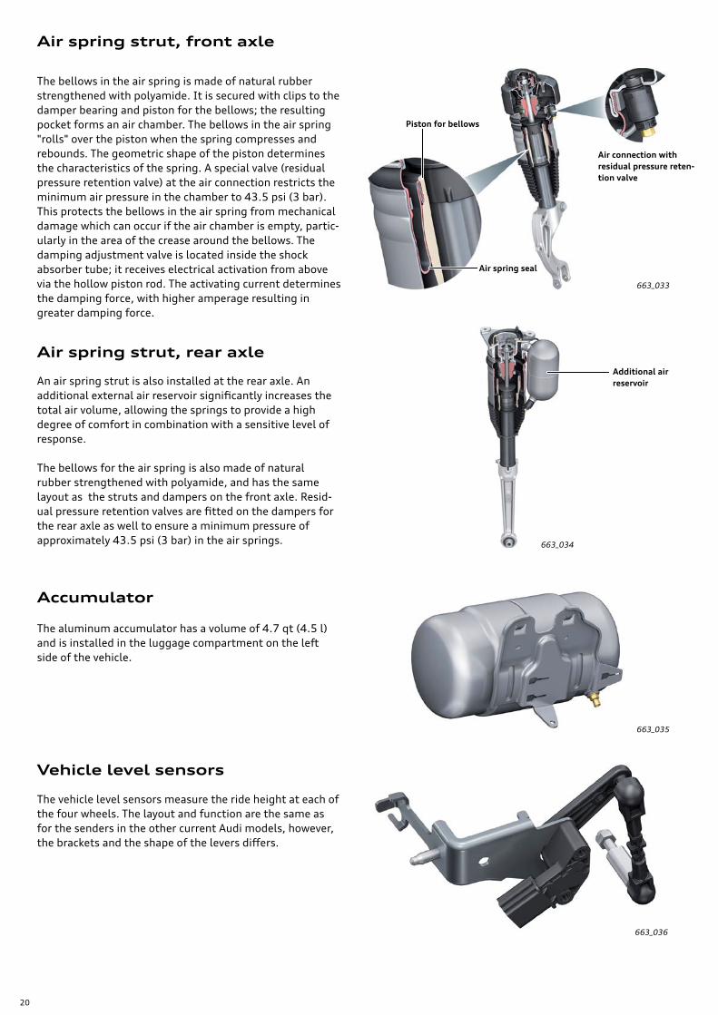
Air spring strut, rear axle
Air spring strut, front axle
Accumulator
Vehicle level sensors
The bellows in the air spring is made of natural rubber strengthened with polyamide. It is secured with clips to the damper bearing and piston for the bellows; the resulting pocket forms an air chamber. The bellows in the air spring "rolls" over the piston when the spring compresses and rebounds. The geometric shape of the piston determines the characteristics of the spring. A special valve (residual pressure retention valve) at the air connection restricts the minimum air pressure in the chamber to 43.5 psi (3 bar). This protects the bellows in the air spring from mechanical damage which can occur if the air chamber is empty, partic-ularly in the area of the crease around the bellows. The damping adjustment valve is located inside the shock absorber tube; it receives electrical activation from above via the hollow piston rod. The activating current determines the damping force, with higher amperage resulting in greater damping force.
The aluminum accumulator has a volume of 4.7 qt (4.5 l) and is installed in the luggage compartment on the left side of the vehicle.
The vehicle level sensors measure the ride height at each of the four wheels. The layout and function are the same as for the senders in the other current Audi models, however, the brackets and the shape of the levers differs.
An air spring strut is also installed at the rear axle. An additional external air reservoir significantly increases the total air volume, allowing the springs to provide a high degree of comfort in combination with a sensitive level of response.
The bellows for the air spring is also made of natural rubber strengthened with polyamide, and has the same layout as the struts and dampers on the front axle. Resid-ual pressure retention valves are fitted on the dampers for the rear axle as well to ensure a minimum pressure of approximately 43.5 psi (3 bar) in the air springs.
Additional air reservoir
21
663_038
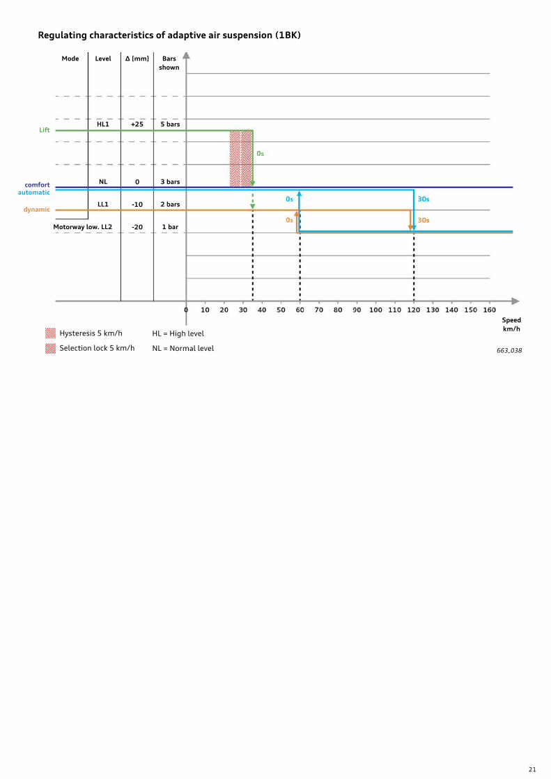
Regulating characteristics of adaptive air suspension (1BK)
Bars shown
∆ [mm]LevelMode
HL1
NL
LL1
Motorway low. LL2
+25 5 bars
3 bars
2 bars
1 bar
Speedkm/h
Lift
comfortautomatic
dynamic
0
-10
-20
Hysteresis 5 km/h
Selection lock 5 km/h
HL = High level
NL = Normal level

22
663_039
System response to faults
Service
In the event of a control module failure, or one of the dampers can no longer be activated, or if the measure-ments from two vehicle level sensors are no longer avail-able, the regulating system will be deactivated.
The damper valves are constructed in such a way that they can provide moderate damping force (basic damping) in a neutral (non-activated) state. This allows the vehicle to maintain driving stability despite the resulting loss of ride comfort.
A yellow damper symbol and a corresponding message alert the driver to the fact that the system has been deactivated.
If the signal from only one of the vehicle level sensors is no longer available, a substitute signal is generated using the measurements from the other senders, and the regulating function remains active.
Drivetrain Control Module J775 is the control master for the air suspension and damping. It can be accessed using Address Word 0074 with the VAS Scan Tool.
A basic setting must be performed after encoding a new control module online. The procedure is the same as for the 2018 Audi Q5 and 2017 Q7 models with adaptive air sus-pension:
First, the vehicle is raised far enough on on a hoist so the wheels are no longer touching the ground (dampers are fully extended). The measurements from the vehicle level sensors are assigned to the positions of the damper pistons and stored by J775.
The vehicle is then lowered to the unladen position. J775 will adjust the suspension to a defined level (reference level). The vehicle’s exact ride height is determined by measuring the distance from the center of the wheel to the center of the wheel arch at all four wheels. The measure-ments are entered in the VAS Scan Tool and sent to Drive-train Control Module J775. This tells the control module the actual ride height of the vehicle, so that it can calculate the correction values necessary to adjust the suspension to the specified level.
With the suspension set to the correct height, the axle load is then calibrated; during this process, air is bled from the air springs one axle at a time. J775 calculates the actual axle load based on the length of time that the solenoid valves are activated and the amount that this lowers the suspension level at each axle (as measured by the vehicle level sensors). Knowing the axle loads is important in order to ensure comfortable damping regulation.
The final step is the calibration of the inertia sensors in J775. To prepare for this procedure, the control module adjusts the suspension very precisely to the normal level. It then takes the measurements from the internal accelera-tion sensors for vertical movement and yaw rate about the x and y axes, and correlates them to the stationary vehicle at the normal level on an even surface.
The basic setting described above should also be performed after replacing one of the air spring struts or removing/re-installing or replacing one of the vehicle level sensors.
A general functional check can be performed using the output check diagnosis function. This checks the function of the compressor, the activation of the damper valves, the fill level of the accumulator and the function of the relevant solenoid valves.
23
From the accessaudi.com Homepage:
› Click on the “App Links”
› Click on the “Academy site CRC”
Click on the Course Catalog Search and select “960293 - The 2019 Audi A8 Audi Running Gear and Suspension Systems”
Please submit any questions or inquiries via the Academy CRC Online Support Form
which is located under the “Support” tab or the “Contact Us” tab of the Academy CRC.
Thank you for reading this eSelf-Study Program and taking the assessment.
The Knowledge Assessment is required for Certification credit.
You can find this Knowledge Assessment at: www.accessaudi.com
An On-Line Knowledge Assessment (exam) is Available for this eSelf-Study Program.
Knowledge assessment

96
02
93
All rights reserved.
Technical specifications subject to
change without notice.
Audi of America, LLC
2200 Ferdinand Porsche Drive
Herndon, VA 20171