the 3,6 m indo-belgian devasthal optical … · the 3.6 m indo-belgian devasthal optical te...
TRANSCRIPT

The 3.6 m Indo-Belgian Devasthal Optical Telescope: Performance results on site
Nathalie Ninane, Christian Bastin, Carlo Flebus and Brijesh Kumar*
Advanced Mechanical and Optical Systems (AMOS s.a.), LIEGE Science Park, B-4031 ANGLEUR (Liège), BELGIUM
* Aryabhatta Research Institute of Observational Sciences (ARIES), Manora Peak, Nainital, 263 129 India
ABSTRACT
AMOS SA has been awarded of the contract for the design, manufacturing, assembly, tests and on site installation (Devasthal, Nainital in central Himalayan region) of the 3.6 m Indo-Belgian Devasthal Optical Telescope (IDOT). The telescope has Ritchey-Chrétien optical configuration with one axial and two side Cassegrain ports. The meniscus primary mirror is active and it is supported by pneumatic actuators. The azimuth axis system is equipped with hydrostatic bearing. After successful factory acceptance at AMOS SA, the telescope has been dismounted, packed, transported, and re-mounted on site. This paper provides the final performances (i.e. image quality, pointing and tracking) measured during sky tests at Devasthal Observatory. Keywords: telescope tests, active optics, image quality, pointing, tracking, IDOT
1. INTRODUCTION After telescope design(1), AIV and factory acceptance tests(2) performed in AMOS assembly hall, IDOT was dismounted and packed to be sent to its site, Devasthal in India. End of 2014, the building was ready for telescope remounting and commissioning. Few months later, first light, and fine tuning could start. And finally, performance and acceptance tests were conducted end of 2015.
After a short telescope overview and requirement discussion, some acceptance test results are presented.
2. TELESCOPE OVERVIEW The main characteristics of the telescope are summarized in Table 1. As shown in Figure 1, the optical combination is a Ritchey-Chrétien type with a Cassegrain focus where the light beam can be directed toward a main port designed for interfacing an instrument with a mass up to 2 tons or toward two side ports for smaller instruments. The mount type is an alt-azimuth. The telescope weights 150 tons. It rotates around the azimuth axis thanks to an hydraulic track(3). The telescope is equipped with an active optic system(4) (AOS) that controls the primary mirror figure and the secondary mirror positioning to keep the telescope wavefront error in the specification for any operational conditions. The primary mirror is a meniscus 165 mm thick, 3700 mm diameter supported by 69 axial actuators and 24 lateral astatic levers. While an Acquisition and Guiding Unit (AGU) aligned on a guide star at the edge of the telescope field of view measures the wavefront and tracking errors, the set of forces applied by the actuators to the mirror is adjusted continuously. In parallel, the Telescope Control System(5) (TCS) computes the telescope trajectory taking into account of the weather conditions, the pointing model of the telescope and the tracking errors measured by the AGU.
Ground-based and Airborne Telescopes VI, edited by Helen J. Hall, Roberto Gilmozzi, Heather K. Marshall, Proc. of SPIE Vol. 9906, 99064E · © 2016 SPIE · CCC code: 0277-786X/16/$18 · doi: 10.1117/12.2232775
Proc. of SPIE Vol. 9906 99064E-1
Downloaded From: http://proceedings.spiedigitallibrary.org/ on 08/08/2016 Terms of Use: http://spiedigitallibrary.org/ss/termsofuse.aspx

Figure 2 shows pictures of the telescope on site. The telescope sizes are: height 13 m, width 7 m and total weight 150 tons. The telescope is installed at Devasthal, North of India, at an altitude of 2540 m. A picture of the dome is in Figure 3; it is a rotating cylinder equipped with as large slit and a wind screen. Large fans all around enable the venting and limit the dome seeing.
Figure 1: ARIES telescope and ray tracing showing the side port and axial port optical path; with 1) the primary mirror, 2) the secondary, 3) the side port focal plane, 4) the side port folding mirror, 5) the field corrector and 6) the axial focal plane.
Type: Ritchey - Chrétien Focal length: 32.4 m (telescope F#/9 with M1 F#/2) Aperture stop: 3.6 m on M1 2 focal plane configurations: Side Port and Axial Port Field of View: 10 arcmin on side ports,
30 arcmin on axial port, (35 arcmin for the AGU)
Operational waveband: 350 nm to 5000 nm M1 characteristics: R = 14638.87 mm CC
K = -1.03296 Optical Φ = 3600 mm, mechanical Φ = 3700 mm
M2 characteristics: R = -4675.30 mm CX K = -2.79561 Optical Φ = 952 mm, mechanical Φ = 980 mm
Distance M1-M2: 5.51 m Back focal length: 2.5 m Focal plane Radius of curvature: 1935.78 mm Scale plate: 157 µm / arcsec (0.006 arcsec/µm)
Table 1: Summary of the telescope characteristics
1
2 3
4 5
6
Proc. of SPIE Vol. 9906 99064E-2
Downloaded From: http://proceedings.spiedigitallibrary.org/ on 08/08/2016 Terms of Use: http://spiedigitallibrary.org/ss/termsofuse.aspx

°
Figure 2: IDOT on site
Figure 3: IDOT building
3. REQUIREMENTS AND REQUIREMENT VERIFICATIONS Table 2 summarizes the main performance requirements specified for 3.6 m IDOT.
Optical main requirements Image quality - Encircled Energy 50% < 0.3 arcsec,
- Encircled Energy 80% < 0.45 arcsec, - Encircled Energy 90% < 0.6 arcsec, For the waveband 350 nm to 1500 nm; without corrector for 10 arcmin FOV.
Proc. of SPIE Vol. 9906 99064E-3
Downloaded From: http://proceedings.spiedigitallibrary.org/ on 08/08/2016 Terms of Use: http://spiedigitallibrary.org/ss/termsofuse.aspx

The telescopethe seeing. Mtelescope levdirectly the stof the wavefrthe measured
A Monte-Carthe encircled The criteria Econstraining work with befrequency of
Tracking accimage at telesquality, the erequirements could also hidwere performfield of regard
The tracking image centroi
Pointing accuimages are sicentroids give
Sky coveragPointing accTracking acc
e requirementMoreover the s
el. The imagetar image, a wront sensor ca
d WFE and the
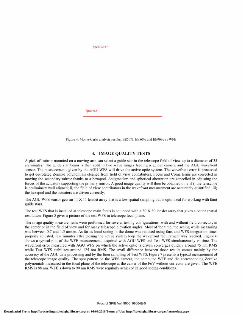
rlo analysis coenergy at λ=
EE80% < 0.45than EE80%
ecause it is reathe WFE; this
curacy can be scope focus w
effect of the severy difficult
de image jittemed for measud with the cor
errors were mids are compu
uracy specificaimply recordees then the po
ge (elevation rcuracy curacy
ts are defined seeing is variae quality requ
wavefront sensamera the seeie encircled ene
onsidering a la1500 nm. Fig
5 arcsec for λ < 0.45 arcsecached in integs criterion can
critical for fwhile integratineeing that wilt to demonstraer produced byuring the axis rresponding ax
measured in reuted and the as
ation is large d while point
ointing error.
Mechanirange) 15 to
< 2 a< 0.1< 0.1< 0.5
Table 2: M
to get an imaable in time, duirements thussor is installedng is averageergy requirem
arge panel of wgure 4 shows t= 1500 nm is c and is reachgrating energyn thus not be v
faint object obng will enlargll produce a hate. Temporaly the telescopcontrol follow
xis speeds and
cording the imssociated stati
enough compting the telesc
ical main requo 87.5° arcsec RMS 1 arcsec RMS 1 arcsec RMS 5 arcsec Peak
Main telescope re
age quality dedepends of thes cannot be did in the focal pd and the wav
ments shall thu
wavefront errothe results forreached for W
hed for a WFEy that is in theverified by tes
bservations thge the image ahigh temporal l integration ipe itself. But pwing errors thd acceleration
mages of a staistics. In paral
pared to the seope toward st
uirements
for 1 minute for 1 hour in for 15 minute
equirements
gradation verye pointing direirectly verifiedplane of the tevefront error cus be identified
or sources detr of 50%, 80%WFE < 210 nmE RMS up toe foot of the Pt.
hat need long and decrease thfrequency tip
is needed to sprior to testinhat are records; no vibration
r with a camellel axis follow
eeing and is thtars covering t
Spec: 0.3
in open loop, close loop,
es in open loop
y small compection and cand in pointing
elescope. In adcan be measurd.
termined the r% and 90% enm; the criteria o 257 nm. CriPSF and is ve
integration tihe telescope r
p/tilt of the imsuppress the sng the trackingded at 200 hz.n appeared.
era at one of thwing errors are
hus easier to vthe field of re
3’’
p.
paring to the cnnot be measu
stars. Insteaddjusting the inred. A relation
relationship ofcircled energyEE50% < 0.3
iteria EE90% ery dependent
ime. The movresolution. As
mage will makeeing but by g on the sky, . In exploring
he foci of the te also recorde
verify. The ceegard. The dis
contribution oured directly ad of measuringntegration timenship between
f the WFE andy respectively3 arcsec is less
is difficult tot of the spatia
vement of thes for the imageke the trackingthe same timefactory tests(2
g the telescope
telescope. Theed.
entroids of starspersion of the
f at g e n
d y. s o al
e e g e 2) e
e
r e
Proc. of SPIE Vol. 9906 99064E-4
Downloaded From: http://proceedings.spiedigitallibrary.org/ on 08/08/2016 Terms of Use: http://spiedigitallibrary.org/ss/termsofuse.aspx
A pick-off marcminutes. Tsensor. The mto get de-rotamoving the sforces of the is preliminarythe hexapod a
The AGU WFguide stars.
The test WFSresolution. Fi
The image quthe center or was between properly adjushows a typicwavefront errwhile Test Waccuracy of ththe telescopepolynomials mRMS is 88 nm
F
mirror mountedThe guide stameasurementsated Zernike psecondary miractuators suppy well alignedand the actuat
FS sensor gets
S that is instaligure 5 gives a
uality measurein the field of0.7 and 1.5 a
usted, few mincal plot of theror measured
WFS stabilizehe AGU data image qualitmeasured in tm. WFE’s dow
Figure 4: Monte
d on a movingar beam is thes given by thepolynomials crror thanks to porting the pr
d; ii) the field tors are driven
s an 11 X 11 l
lled at telescoa picture of th
ements were pf view and foarcsec. As farnutes after cle WFE measuwith AGU Ws around 125processing an
ty. The spot pthe focal planewn to 90 nm R
Sp
e-Carlo analysis
4. IMAGg arm can seleen split in tw AGU WFS w
cleaned from a hexapod. A
rimary mirror.of view contr
n correctly.
lenslet array th
pe main focushe test WFS in
performed forr many telesc
r as local seeinlosing the actiurements acqu
WFS on which5 nm RMS. Tnd by the finerpattern on thee of the telescRMS were reg
Spec: 0.45’’
pec: 0.6’’
s results; EE50%
GE QUALITect a guide sta
wo wave rangwill drive the field of view
Astigmatism a. A good imagributors in the
hat is a low sp
s is equipped n telescope foc
r several testincope elevationng in the domive system louired with AGh the active oThe small difr sampling of e WFS cameracope at the cengularly achieve
%, EE80% and
TY TESTSar in the telesces feeding a active optic scontributors.
and spherical ge quality will wavefront m
patial samplin
with a 30 X 3cal plane.
ng configuratin angles. Mostme was reduceoop the wavefGU WFS andoptic is drivenfference betwTest WFS. Fia, the computnter of the Foed in good see
EE90% vs WF
cope field of vguider camer
system. The wFocus and Caberration arel then be obtaeasurement ar
ng but is optim
30 lenslet arra
ions; with andt of the time, ed using fans front requiremd Test WFS sin converges qween those resigure 7 presented WFE and V without coreing condition
FE
view up to a dra and the AGwavefront erroComa terms are cancelled in
ained only if i)re accurately q
mized for work
ay that gives a
d without fieldthe seeing whand WFS inte
ment was reacimultaneously
quickly aroundsults comes m
nts a typical mthe correspon
rrector are givns.
diameter of 35GU wavefronor is processedre corrected inn adjusting the) the telescopequantified; iii)
king with fain
a better spatia
d corrector, inhile measuringegration timesched. Figure 6y vs time. Thed 75 nm RMSmainly by the
measurement onding Zernikeven. The WFE
5 nt d n e e )
nt
al
n g s 6 e S e f e E
Proc. of SPIE Vol. 9906 99064E-5
Downloaded From: http://proceedings.spiedigitallibrary.org/ on 08/08/2016 Terms of Use: http://spiedigitallibrary.org/ss/termsofuse.aspx

ARIES - ACS In CL - WFEH1P5722_ TesiCL_2015_11_03_1234116px1
ÑFcc
600
500
400
AGU WFS-4 -Test WFS
* Test WES - focus removed
E 300Lai
200
100
023 30 23:40 23:50 00:00
Time00:10 00.20 00 30
Figure 5: Test WFS mounted in telescope focal plane
Figure 6: Telescope WFE at the start of the closing of the active loop
Corrector
Test WFS
Proc. of SPIE Vol. 9906 99064E-6
Downloaded From: http://proceedings.spiedigitallibrary.org/ on 08/08/2016 Terms of Use: http://spiedigitallibrary.org/ss/termsofuse.aspx

Measurement, 151104 h00m11 s04 TEST_WFS.shz
Mean 3.76879e -018
RMS 0.0883415
P -V 0.618987
Max 0.255609
Min -0.363378
0.2
0.1
-0.1
-0.2
-0.3
24.05.2016
Corr. wave - front, 151104 h00m11 s04 TEST_WFS.shz
i i i i i r i2 3 4 5 6 7 8 9 10 11 12
x/rnm
Zernike coefficients (ISO)
Residuum: 0.3166121 0.042922
CO 0.0333084 pistonCl -0.00941796 tilt, xC2 -0.111324 tilt, yC3 -0.0870605 defocusC4 0.117482 Ast. 0°, 1stC5 0.0283068 Ast. 45°, 1stC6 0.00649092 Coma xC7 0.162622 Coma yC8 0.118827 Sph. ab.C9 0.0528059 trifoil 0°C10 -0.00338887 trifoil 30°C11 0.044095 Ast. 0 °, 2ndC12 0.0109573 Ast. 45 °, 2ndC13 0.00764345C14 -0.0265882C15 -0.0630979 radial termC16 -0.0158248 tetrafoil 0°C17 0.00578928 tetrafoil 22,5°C18 0.011438C19 -0.0165362C20 -0.0110114C21 0.00928714C22 -0.0539363C23 0.0255842C24 0.0696476 radial term
Figure 7: Telescope WFE: WFS spot pattern, WFE map and Zernike coefficients (in µm).
Proc. of SPIE Vol. 9906 99064E-7
Downloaded From: http://proceedings.spiedigitallibrary.org/ on 08/08/2016 Terms of Use: http://spiedigitallibrary.org/ss/termsofuse.aspx

To cross-checand the telescHIP117695 sseconds. FiguIt has to be nused). The fig
For the pointmodel to drivimages. The cThe main porcentroids are
Y [a
rcse
c]
ck the excellencope resolutioseparated by ure 9, double snoticed that thgures show th
Figu
ing tests, imagve the axes towcentroids of thrt pointing tesshown. The p
-1.5 -1-1.5
-1
-0.5
0
0.5
1
1.5
[]
nt results, imaon that can be 1.2 arcsec, pstar HIP11764he spot elongaat 0.6 arcsec i
Figu
ure 9: Double st
5. ges of 30 starwards the selehese stars are st result is givpointing error
-0.5 0X [arcsec]
ages of doubleachieved dur
pointed at an 46 separated bation comes fis clearly reso
ure 8: Double st
tar HIP117646
POINTINGrs spread all oected stars. Focomputed. Th
ven in Figure RMS is < 1.2
0.5 1 1.
0.6 arcsec
e stars were rering good seei
altitude anglby 0.6 arcsec, from the air wlved despite o
tar HIP117695 r
recorded with I
G AND TRAover the field oor this test no phe centroids d10. The poin arcsec RMS
5
Nor
mal
ized
inte
nsiti
y
1.2 arcsec
ecorded to vering nights. Figle of 60° aboexposure tim
wavelength diof the seeing (
recorded with I
IDOT: picture a
ACKING TEof regard are rpointing corre
dispersion in ronting axes of tfor a requirem
-1.5 -10
0.2
0.4
0.6
0.8
1
Nor
mal
ized
inte
nsiti
y
rify the accordgure 8 shows
ove horizon wme 1.5 secondsispersion (no which was go
IDOT
and intensity pr
ESTS recorded. Theection is applioot mean squathe star sampl
ment of 2 arcse
-0.5 0Double star axis
X: -0.3162Y: 1
X: -Y:
dance of the ma picture of t
with an exposs at an altitudenarrow bandp
ood that day).
rofile.
e telescope used before recoare gives the ple and the disec RMS.
0.5 1[arcsec]
X: 0.2641Y: 0.9811
-0.013410.7779
measured WFEhe double star
sure time of 4e angle of 45°pass filter was
es its pointingording the starpointing errorspersion of the
1.5
E r 4 °. s
g r r. e
Proc. of SPIE Vol. 9906 99064E-8
Downloaded From: http://proceedings.spiedigitallibrary.org/ on 08/08/2016 Terms of Use: http://spiedigitallibrary.org/ss/termsofuse.aspx

180
150
210
9080
120 60
* 60
..
Va."'
-
240 300
270
30
330
2
15
D.5
co
_ 0
UW
-a5
-1 5
2
Main Port Pointing test 29/11/2015Spec'. 2 eresec RMS, Achieved: I.1939eresec RMS
+
++ +
0 0.5 1 1.5 2 2.5RA axis laresec]
Telescope trajectory in Azimuth - Altitude coordinatesMeasure dater 2015_12_1
---
+;)
A Start- Trajectory- Limits
0.5
Open Loop Tracking test - Specification analysisFilename: 20151201 000200 Tcam MP OL
0.4 -
yN
0.3
`m
R0.2 -
0.1
RMS on 1 min - p +2o: 0.062spec on 1 minPeak on 15 min - max: 0.22spec on 15 min
00:10 00:15 00:20 00:25Time
Figure 10: Main port pointing test; at the left the star sample in the telescope field of regard, at the right the dispersion of the star
centroids while sighting them with the telescope.
The tracking error is specified in open and closed loop of the guider. The tracking error is measured in recording the star image on a CCD camera in the telescope focal plane while tracking. The statistics on the movements of the centroids give the tracking error. Centroid positioning were measured with integration time of 30 sec. The measurements were repeated several times for covering the particular axis movements that appear in the field of regard of the telescope. Close to zenith, azimuth and rotator axes accelerate and rotate larger angles in a given lapse of time; close to Polaris the axes are nearly still or can change their moving direction. Close to horizon the seeing becomes worst, good measurements are then difficult to catch. Except for measurements close to horizon the tracking requirements were met. The discrepancy at horizon is obviously due to the higher seeing present there. Typical test results in open and close loop tracking are given in figure 11 and 12.
Figure 11: Open loop tracking test; the star trajectory while measuring at the left, at the right the plot in blue gives the RMS error for data acquired during 1 minute, the plot in green is the peak deviation of the centroid for sliding elapsed time of 15 minutes.
Proc. of SPIE Vol. 9906 99064E-9
Downloaded From: http://proceedings.spiedigitallibrary.org/ on 08/08/2016 Terms of Use: http://spiedigitallibrary.org/ss/termsofuse.aspx

Telescope trajectory in Azimuth - Altitude coordinatesMeasure date: 2015_12_2
N Start- Trajectory- Limits
S
E
Closed Loop Tracking test - Specification analysisFilename: 20151202 234800 Tcam MP CL
RMS on 1 min - mean: 0.054RMS on 1 hour - mean: 0.083specification
0.1
ÚNUL
LIl Ilit
I
A A I
i
rf---(0
LLI
0.05
1
V
1
o
V II yV
00:00 00:10 00:20 00:30 00:40 00:50Time
Figure 12: Close loop tracking test; the star trajectory while measuring at the left, at the right the plot in blue gives the RMS error for data acquired during 1 minute, the plot in green is the RMS deviation of the centroid for sliding elapsed time of 1 hour.
6. CONCLUSION IDOT commissioning and acceptance test campaign happened successfully despite of the difficult context. Indeed, the specifications of the telescope are written such that the performance is limited by the seeing and the customer is willing an end to end acceptance test. The first difficulty is to transform theoretical specifications into measurable parameters in observing conditions. These parameters have to be sufficiently reliable despite of the seeing and in accordance with the customer final need. The image quality requirements expressed in Encircled Energy was transformed in wavefront error specification. The customer who are astronomers are not used to work with this criteria and would like to get an independent way to prove the image quality with a measurement related to image resolution. Fortunately some good seeing nights enabled to demonstrate the accordance of what was measured with the wavefront sensor and the telescope quality in acquiring double star images.
It has to be reminded that a telescope is a complex machine with some very accurate sub-systems and with finely tuned controls. The obtained quality is the result of an attentive work on every sub-system.
Before sending the telescope on site, it was completely mounted, tuned and tested in the factory integration hall (2). Despite of the fact that the hall seeing was bad (2 arc seconds in the best case), the debugging and experience acquired at that time were very precious on site. Time was spared and all the attention could be put on the fine tuning and the alignments that are necessary for reaching the specifications.
IDOT is the first 4-m class telescope equipped with an active primary mirror realized by AMOS; its success is very encouraging for the new projects granted to AMOS; DKIST Primary mirror cell(6) and the Doğu Anadolu Gözlemevi (DAG) telescope(7) that uses this demonstrated technology.
7. ACKNOWLEDGEMENT This work has been performed under ARIES contract reference 1985-14-02. AMOS is very grateful towards ARIES team for having put their confidence in AMOS team for the design and manufacturing of the 3.6 m telescope.
Proc. of SPIE Vol. 9906 99064E-10
Downloaded From: http://proceedings.spiedigitallibrary.org/ on 08/08/2016 Terms of Use: http://spiedigitallibrary.org/ss/termsofuse.aspx

At the end of the commissioning and test campaign, ARIES large field camera was installed at the focus of the telescope. This gave us (ARIES and AMOS team) the opportunity to acquire a first “astronomic” image. Thanks for having spent this moment together. The image is presented in Figure 13 and was acquired during the first working night of the telescope Imager instrument (which was thus not tuned nor aligned at that time). Seeing during this night was quite bad (~1.5 arcsec).
Figure 13: Crab Nebula; composition of 2 images (R and V bands); acquired with IDOT and ARIES large field camera.
8. REFERENCES
[1] Ninane N., Flebus C. and Kumar B., "The 3.6 m Indo-Belgian Devasthal Optical Telescope: general description",
Proc. SPIE 8444-67 (2012) [2] Ninane N., Bastin C., Deville J., Michel F., Pierard M., Gabriel E., Flebus C. and Omar A., "The 3.6 m Indo-Belgian
Devasthal Optical Telescope: assembly, integration, and tests at AMOS", Proc. SPIE 8444-102 (2012). [3] Deville J., Bastin C. and Pierard M., "The 3.6 m Indo-Belgian Devasthal Optical Telescope: the hydrostatic azimuth
bearing", Proc. SPIE 8444-150 (2012) [4] Pierard M., Schumacher J.M., Flebus C. and Ninane N., "The 3.6 m Indo-Belgian Devasthal Optical Telescope: the
active M1 mirror support", Proc. SPIE 8444-186 (2012) [5] Gabriel E., Bastin C., Piérard M., "The 3.6 m Indo-Belgian Devasthal Optical Telescope: the control system", Proc.
SPIE 8451-82 (2012) [6] Gregory P. Lousberg, Vincent Moreau, Jean-Marc Schumacher, Maxime Piérard, Aude Somja, Pierre Gloesener,
Carlo Flebus, “Design and analysis of an active optics system for a 4-m telescope mirror combining hydraulic and pneumatic supports”, Proc. SPIE 9626-24 (2015)
[7] Grégory P. Lousberg, Emeric Mudry, Christian Bastin, Jean-Marc Schumacher, Eric Gabriel, Olivier Pirnay, Carlo Flebus, “Active optics system for the 4m telescope of the Eastern Anatolia Observatory (DAG)”, Proc. SPIE 9912-223 (2016)
Proc. of SPIE Vol. 9906 99064E-11
Downloaded From: http://proceedings.spiedigitallibrary.org/ on 08/08/2016 Terms of Use: http://spiedigitallibrary.org/ss/termsofuse.aspx