the 3ds max interface - managementboek.nl · c01.indd 24-05-2014 07:27 pm chapter 1 the 3ds max...
TRANSCRIPT
c01.indd 24-05-2014 07:27 PM
Chapter 1
The 3ds Max InterfaceThe Autodesk® 3ds Max® software interface is where you view and work with your scene. This chapter explains its basic operations and tools. You can use this chapter as a reference as you work through the rest of this book, although the following chapters and their exercises will orient you to the 3ds Max user interface (UI) quickly. It’s important to be in front of your computer when you read this chapter so you can try out techniques as we discuss them.
In this chapter, you will learn to:
▶▶ Navigate the workspace
▶▶ Transform objects using gizmos
▶▶ Model with the Graphite Modeling Tools set
▶▶ Manage animation with the time slider and track bar
Navigate the WorkspaceThe following sections present a brief rundown of what you need to know about the 3ds Max user interface and how to navigate in the 3D workspace.
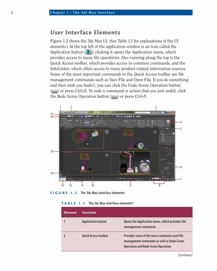
When you first open the program, you will see the Default workspace (Figure 1.1). The Workspace feature controls the interface, and with this menu you can define as many different workspaces as you want. You can then switch among them from the drop-down list on the Quick Access tool-bar or the Current Workspaces list on the Manage Workspaces dialog.
F I g u r e 1 . 1 Workspace drop-down menu
CertificationObjective
COPYRIG
HTED M
ATERIAL
2 C h a p t e r 1 • T h e 3 d s M a x I n t e r f a c e
c01.indd 24-05-2014 07:27 PM
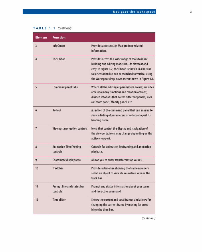
user Interface elementsFigure 1.2 shows the 3ds Max UI. (See Table 1.1 for explanations of the UI elements.) At the top left of the application window is an icon called the Application button ( ); clicking it opens the Application menu, which provides access to many file operations. Also running along the top is the Quick Access toolbar, which provides access to common commands, and the InfoCenter, which offers access to many product-related information sources. Some of the most important commands in the Quick Access toolbar are file management commands such as Save File and Open File. If you do something and then wish you hadn’t, you can click the Undo Scene Operation button ( ) or press Ctrl+Z. To redo a command or action that you just undid, click the Redo Scene Operation button ( ) or press Ctrl+Y.
1 2 3
4
5
6
7
8910111213
14
15
1617
F I g u r e 1 . 2 The 3ds Max interface elements
t a b l e 1 . 1 The 3ds Max interface elements*
element Function
1 Application button Opens the Application menu, which provides file management commands.
2 Quick Access toolbar Provides some of the most commonly used file management commands as well as Undo Scene Operation and Redo Scene Operation.
(Continues)
N a v i g a t e t h e W o r k s p a c e 3
c01.indd 24-05-2014 07:27 PM
element Function
3 InfoCenter Provides access to 3ds Max product-related information.
4 The ribbon Provides access to a wide range of tools to make building and editing models in 3ds Max fast and easy. In Figure 1.2, the ribbon is shown in a horizon-tal orientation but can be switched to vertical using the Workspace drop-down menu shown in Figure 1.1.
5 Command panel tabs Where all the editing of parameters occurs; provides access to many functions and creation options; divided into tabs that access different panels, such as Create panel, Modify panel, etc.
6 Rollout A section of the command panel that can expand to show a listing of parameters or collapse to just its heading name.
7 Viewport navigation controls Icons that control the display and navigation of the viewports; icons may change depending on the active viewport.
8 Animation Time/Keying controls
Controls for animation keyframing and animation playback.
9 Coordinate display area Allows you to enter transformation values.
10 Track bar Provides a timeline showing the frame numbers; select an object to view its animation keys on the track bar.
11 Prompt line and status bar controls
Prompt and status information about your scene and the active command.
12 Time slider Shows the current and total frames and allows for changing the current frame by moving (or scrub-bing) the time bar.
(Continues)
t a b l e 1 . 1 (Continued)
4 C h a p t e r 1 • T h e 3 d s M a x I n t e r f a c e
c01.indd 24-05-2014 07:27 PM
element Function
13 MAXScript Mini Listener A command-prompt window for the MAXScript programming language. The window is useful for performing interactive work and developing small code fragments.
14 Viewport Layout tab bar This is an easy-access tab for quickly changing view-port layouts. Preset layouts can be added to the menu on the tab bar.
15 Viewports You can choose different views to display in these four viewports as well as different layouts from the viewport label menus.
16 Main toolbar Provides quick access to tools and dialog boxes for many of the most common tasks.
17 Menu bar Provides access to commands grouped by category.
*The numerals in the first column refer to labels in Figure 1.2.
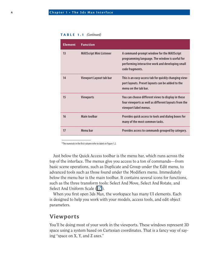
Just below the Quick Access toolbar is the menu bar, which runs across the top of the interface. The menus give you access to a ton of commands—from basic scene operations, such as Duplicate and Group under the Edit menu, to advanced tools such as those found under the Modifiers menu. Immediately below the menu bar is the main toolbar. It contains several icons for functions, such as the three transform tools: Select And Move, Select And Rotate, and Select And Uniform Scale ( ).
When you first open 3ds Max, the workspace has many UI elements. Each is designed to help you work with your models, access tools, and edit object parameters.
ViewportsYou’ll be doing most of your work in the viewports. These windows represent 3D space using a system based on Cartesian coordinates. That is a fancy way of say-ing “space on X, Y, and Z axes.”
t a b l e 1 . 1 (Continued)
N a v i g a t e t h e W o r k s p a c e 5
c01.indd 24-05-2014 07:27 PM
You can visualize X as left-right, Y as in-out (into and out of the screen from the Top viewport), and Z as up-down within the Perspective and Camera viewports. In the orthographic viewports, you can visualize Y as up-down and Z as in-out. The coordinates are expressed as a set of three numbers, such as (0, 3, –7). These coor-dinates represent a point that is at 0 on the X-axis, 3 units up on the Y-axis, and 7 units back on the Z-axis.
Four-Viewport layout tab bar
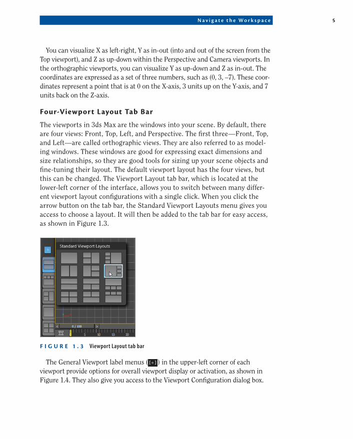
The viewports in 3ds Max are the windows into your scene. By default, there are four views: Front, Top, Left, and Perspective. The first three—Front, Top, and Left—are called orthographic views. They are also referred to as model-ing windows. These windows are good for expressing exact dimensions and size relationships, so they are good tools for sizing up your scene objects and fine-tuning their layout. The default viewport layout has the four views, but this can be changed. The Viewport Layout tab bar, which is located at the lower-left corner of the interface, allows you to switch between many differ-ent viewport layout configurations with a single click. When you click the arrow button on the tab bar, the Standard Viewport Layouts menu gives you access to choose a layout. It will then be added to the tab bar for easy access, as shown in Figure 1.3.
F I g u r e 1 . 3 Viewport Layout tab bar
The General Viewport label menus ( ) in the upper-left corner of each viewport provide options for overall viewport display or activation, as shown in Figure 1.4. They also give you access to the Viewport Configuration dialog box.
6 C h a p t e r 1 • T h e 3 d s M a x I n t e r f a c e
c01.indd 24-05-2014 07:27 PM
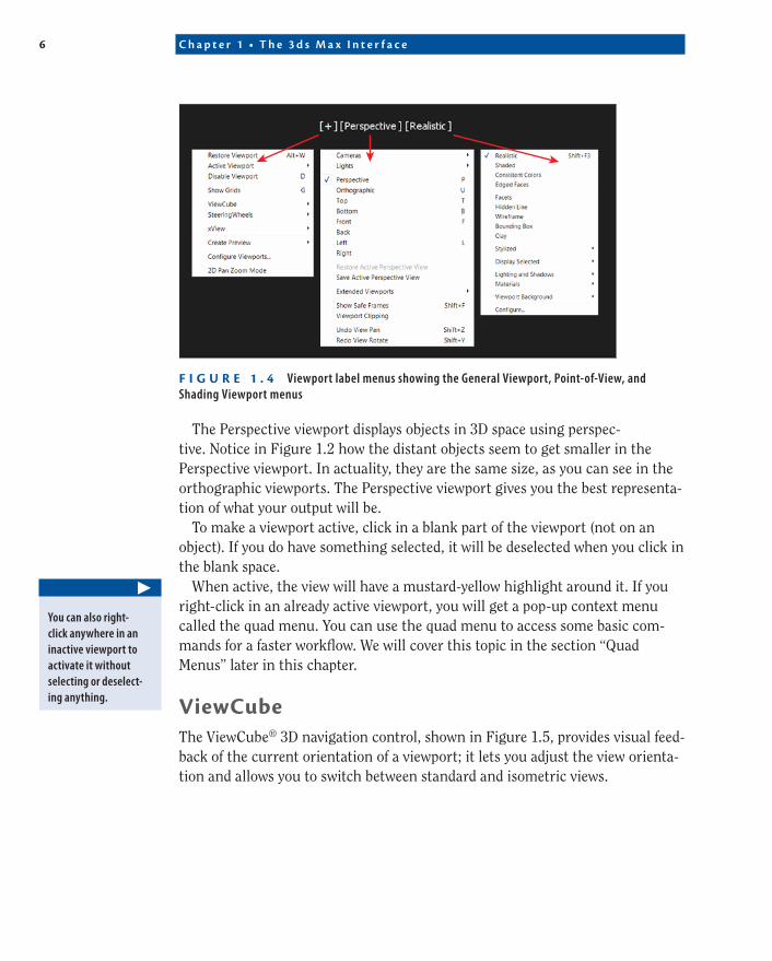
F I g u r e 1 . 4 Viewport label menus showing the General Viewport, Point-of-View, and Shading Viewport menus
The Perspective viewport displays objects in 3D space using perspec-tive. Notice in Figure 1.2 how the distant objects seem to get smaller in the Perspective viewport. In actuality, they are the same size, as you can see in the orthographic viewports. The Perspective viewport gives you the best representa-tion of what your output will be.
To make a viewport active, click in a blank part of the viewport (not on an object). If you do have something selected, it will be deselected when you click in the blank space.
When active, the view will have a mustard-yellow highlight around it. If you right-click in an already active viewport, you will get a pop-up context menu called the quad menu. You can use the quad menu to access some basic com-mands for a faster workflow. We will cover this topic in the section “Quad Menus” later in this chapter.
ViewCubeThe ViewCube® 3D navigation control, shown in Figure 1.5, provides visual feed-back of the current orientation of a viewport; it lets you adjust the view orienta-tion and allows you to switch between standard and isometric views.
▶
You can also right-click anywhere in an inactive viewport to activate it without selecting or deselect-ing anything.
N a v i g a t e t h e W o r k s p a c e 7
c01.indd 24-05-2014 07:27 PM
Home button: Resets viewport to Home view.
Using the left mouse button, you canswitch to one of the available preset views or rotate the current view.
Compass indicates the north direction for the scene. You can toggle the compass display below the ViewCube and specify its orientation with the compass settings.
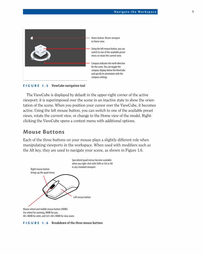
F I g u r e 1 . 5 ViewCube navigation tool
The ViewCube is displayed by default in the upper-right corner of the active viewport; it is superimposed over the scene in an inactive state to show the orien-tation of the scene. When you position your cursor over the ViewCube, it becomes active. Using the left mouse button, you can switch to one of the available preset views, rotate the current view, or change to the Home view of the model. Right-clicking the ViewCube opens a context menu with additional options.
Mouse buttonsEach of the three buttons on your mouse plays a slightly different role when manipulating viewports in the workspace. When used with modifiers such as the Alt key, they are used to navigate your scene, as shown in Figure 1.6.
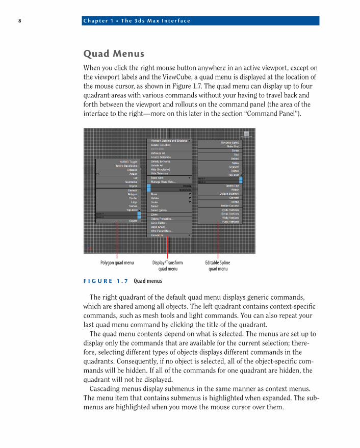
Specialized quad menus become available when you right-click with Shift or Ctrl or Alt in any standard viewport.
Mouse wheel and middle mouse button (MMB). Use wheel for zooming, MMB for pan, Alt+MMB for orbit, and Ctrl+Alt+MMB for slow zoom.
Right mouse button brings up the quad menu.
Left mouse button
F I g u r e 1 . 6 Breakdown of the three mouse buttons
8 C h a p t e r 1 • T h e 3 d s M a x I n t e r f a c e
c01.indd 24-05-2014 07:27 PM
Quad MenusWhen you click the right mouse button anywhere in an active viewport, except on the viewport labels and the ViewCube, a quad menu is displayed at the location of the mouse cursor, as shown in Figure 1.7. The quad menu can display up to four quadrant areas with various commands without your having to travel back and forth between the viewport and rollouts on the command panel (the area of the interface to the right—more on this later in the section “Command Panel”).
Polygon quad menu Display/Transform quad menu
Editable Spline quad menu
F I g u r e 1 . 7 Quad menus
The right quadrant of the default quad menu displays generic commands, which are shared among all objects. The left quadrant contains context-specific commands, such as mesh tools and light commands. You can also repeat your last quad menu command by clicking the title of the quadrant.
The quad menu contents depend on what is selected. The menus are set up to display only the commands that are available for the current selection; there-fore, selecting different types of objects displays different commands in the quadrants. Consequently, if no object is selected, all of the object-specific com-mands will be hidden. If all of the commands for one quadrant are hidden, the quadrant will not be displayed.
Cascading menus display submenus in the same manner as context menus. The menu item that contains submenus is highlighted when expanded. The sub-menus are highlighted when you move the mouse cursor over them.
N a v i g a t e t h e W o r k s p a c e 9
c01.indd 24-05-2014 07:27 PM
To close the menu, right-click anywhere on the screen or move the mouse cursor away from the menu and click the left mouse button. To reselect the last-selected command, click in the title of the quadrant of the last menu item. The last menu item selected is highlighted when the quadrant is displayed.
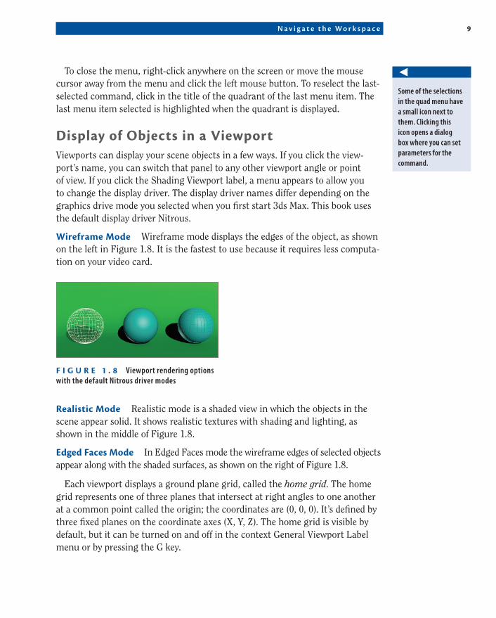
Display of Objects in a ViewportViewports can display your scene objects in a few ways. If you click the view-port’s name, you can switch that panel to any other viewport angle or point of view. If you click the Shading Viewport label, a menu appears to allow you to change the display driver. The display driver names differ depending on the graphics drive mode you selected when you first start 3ds Max. This book uses the default display driver Nitrous.
Wireframe Mode Wireframe mode displays the edges of the object, as shown on the left in Figure 1.8. It is the fastest to use because it requires less computa-tion on your video card.
F I g u r e 1 . 8 Viewport rendering options with the default Nitrous driver modes
realistic Mode Realistic mode is a shaded view in which the objects in the scene appear solid. It shows realistic textures with shading and lighting, as shown in the middle of Figure 1.8.
edged Faces Mode In Edged Faces mode the wireframe edges of selected objects appear along with the shaded surfaces, as shown on the right of Figure 1.8.
Each viewport displays a ground plane grid, called the home grid. The home grid represents one of three planes that intersect at right angles to one another at a common point called the origin; the coordinates are (0, 0, 0). It’s defined by three fixed planes on the coordinate axes (X, Y, Z). The home grid is visible by default, but it can be turned on and off in the context General Viewport Label menu or by pressing the G key.
◀
Some of the selections in the quad menu have a small icon next to them. Clicking this icon opens a dialog box where you can set parameters for the command.
1 0 C h a p t e r 1 • T h e 3 d s M a x I n t e r f a c e
c01.indd 24-05-2014 07:27 PM
Selecting Objects in a Viewport
Click an object to select it in a viewport. If the object is displayed in Wireframe mode, its wireframe turns white while it is selected. If the object is displayed in a Realistic or Shaded mode, a white bracket appears around the object. This is set by default in the Perspective view; to toggle the selection brackets on and off use the keyboard shortcut J.
To select multiple objects, hold down the Ctrl key as you click additional objects to add to your selection. If you Alt+click an active object, you will dese-lect it. You can clear all your active selections by clicking in an empty area of the viewport.
Changing/Maximizing the Viewports
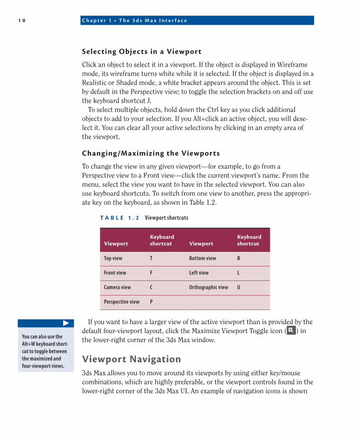
To change the view in any given viewport—for example, to go from a Perspective view to a Front view—click the current viewport’s name. From the menu, select the view you want to have in the selected viewport. You can also use keyboard shortcuts. To switch from one view to another, press the appropri-ate key on the keyboard, as shown in Table 1.2.
t a b l e 1 . 2 Viewport shortcuts
ViewportKeyboard shortcut Viewport
Keyboard shortcut
Top view T Bottom view B
Front view F Left view L
Camera view C Orthographic view U
Perspective view P
If you want to have a larger view of the active viewport than is provided by the default four-viewport layout, click the Maximize Viewport Toggle icon ( ) in the lower-right corner of the 3ds Max window.
Viewport Navigation3ds Max allows you to move around its viewports by using either key/mouse combinations, which are highly preferable, or the viewport controls found in the lower-right corner of the 3ds Max UI. An example of navigation icons is shown
▶
You can also use the Alt+W keyboard short-cut to toggle between the maximized and four-viewport views.
Tr a n s f o r m i n g O b j e c t s U s i n g G i z m o s 1 1
c01.indd 24-05-2014 07:27 PM
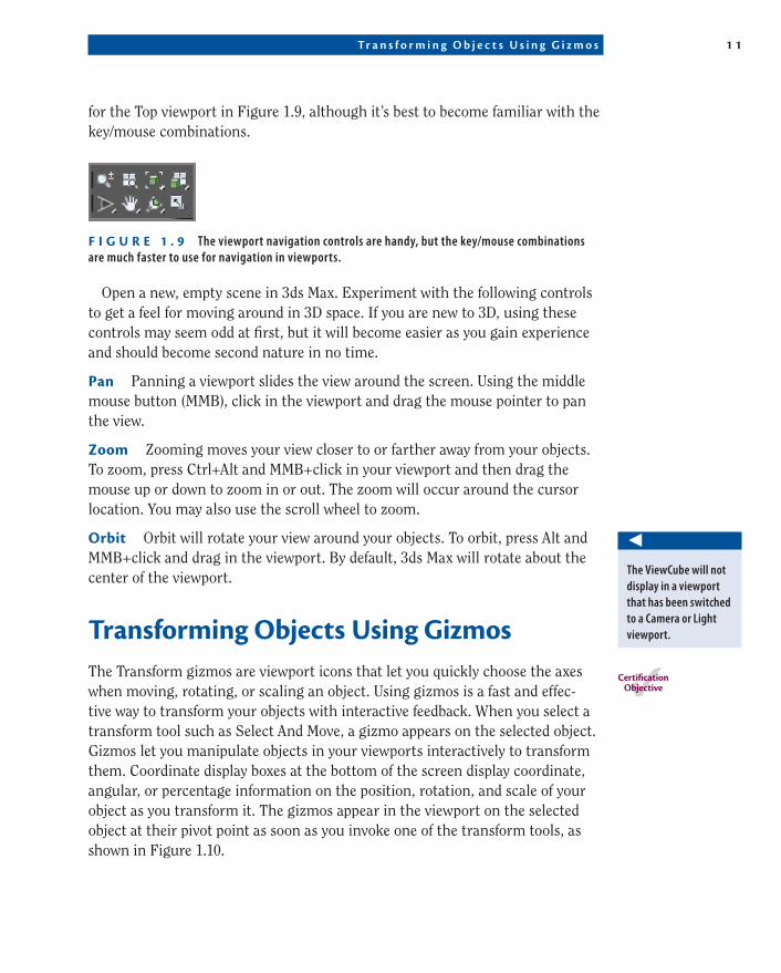
for the Top viewport in Figure 1.9, although it’s best to become familiar with the key/mouse combinations.
F I g u r e 1 . 9 The viewport navigation controls are handy, but the key/mouse combinations are much faster to use for navigation in viewports.
Open a new, empty scene in 3ds Max. Experiment with the following controls to get a feel for moving around in 3D space. If you are new to 3D, using these controls may seem odd at first, but it will become easier as you gain experience and should become second nature in no time.
pan Panning a viewport slides the view around the screen. Using the middle mouse button (MMB), click in the viewport and drag the mouse pointer to pan the view.
Zoom Zooming moves your view closer to or farther away from your objects. To zoom, press Ctrl+Alt and MMB+click in your viewport and then drag the mouse up or down to zoom in or out. The zoom will occur around the cursor location. You may also use the scroll wheel to zoom.
Orbit Orbit will rotate your view around your objects. To orbit, press Alt and MMB+click and drag in the viewport. By default, 3ds Max will rotate about the center of the viewport.
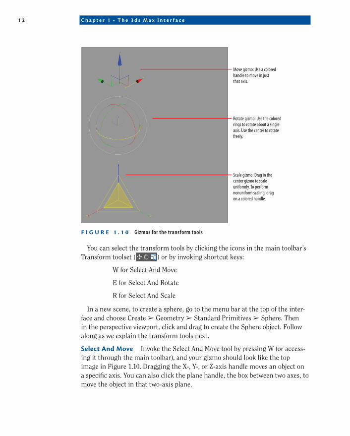
transforming Objects using gizmosThe Transform gizmos are viewport icons that let you quickly choose the axes when moving, rotating, or scaling an object. Using gizmos is a fast and effec-tive way to transform your objects with interactive feedback. When you select a transform tool such as Select And Move, a gizmo appears on the selected object. Gizmos let you manipulate objects in your viewports interactively to transform them. Coordinate display boxes at the bottom of the screen display coordinate, angular, or percentage information on the position, rotation, and scale of your object as you transform it. The gizmos appear in the viewport on the selected object at their pivot point as soon as you invoke one of the transform tools, as shown in Figure 1.10.
◀
The ViewCube will not display in a viewport that has been switched to a Camera or Light viewport.
CertificationObjective
1 2 C h a p t e r 1 • T h e 3 d s M a x I n t e r f a c e
c01.indd 24-05-2014 07:27 PM
Move gizmo: Use a colored handle to move in just that axis.
Rotate gizmo: Use the colored rings to rotate about a single axis. Use the center to rotate freely.
Scale gizmo: Drag in the center gizmo to scale uniformly. To perform nonuniform scaling, drag on a colored handle.
F I g u r e 1 . 1 0 Gizmos for the transform tools
You can select the transform tools by clicking the icons in the main toolbar’s Transform toolset ( ) or by invoking shortcut keys:
W for Select And Move
E for Select And Rotate
R for Select And Scale
In a new scene, to create a sphere, go to the menu bar at the top of the inter-face and choose Create ➢ Geometry ➢ Standard Primitives ➢ Sphere. Then in the perspective viewport, click and drag to create the Sphere object. Follow along as we explain the transform tools next.
Select and Move Invoke the Select And Move tool by pressing W (or access-ing it through the main toolbar), and your gizmo should look like the top image in Figure 1.10. Dragging the X-, Y-, or Z-axis handle moves an object on a specific axis. You can also click the plane handle, the box between two axes, to move the object in that two-axis plane.
G r a p h i t e M o d e l i n g To o l s S e t 1 3
c01.indd 24-05-2014 07:27 PM
Select and rotate Invoke the Select And Rotate tool by pressing E, and your gizmo will turn into three circles, as shown in the middle image in Figure 1.10. You can click one of the colored circles to rotate the object on the axis only, or you can click anywhere between the circles to freely rotate the selected object in all three axes.
Select and Scale Invoke the Select And Scale tool by pressing the R key, and your gizmo will turn into a triangle, as shown in the bottom image of Figure 1.10. Clicking and dragging anywhere inside the yellow triangle will scale the object uni-formly on all three axes. By selecting the red, green, or blue handle for the appropri-ate axis, you can scale along one axis only. You can also scale an object on a plane between two axes by selecting the side of the yellow triangle between two axes.
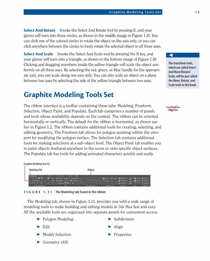
graphite Modeling tools SetThe ribbon interface is a toolbar containing these tabs: Modeling, Freeform, Selection, Object Paint, and Populate. Each tab comprises a number of panels and tools whose availability depends on the context. The ribbon can be oriented horizontally or vertically. The default for the ribbon is horizontal, as shown ear-lier in Figure 1.2. The ribbon contains additional tools for creating, selecting, and editing geometry. The Freeform tab allows for polygon painting within the view-port for modifying the polygon surface. The Selection tab contains additional tools for making selections at a sub-object level. The Object Paint tab enables you to paint objects freehand anywhere in the scene or onto specific object surfaces. The Populate tab has tools for adding animated characters quickly and easily.
Modeling Tab Ribbon
Graphite Modeling Tool Set
F I g u r e 1 . 1 1 The Modeling tab found in the ribbon
The Modeling tab, shown in Figure 1.11, provides you with a wide range of modeling tools to make building and editing models in 3ds Max fast and easy. All the available tools are organized into separate panels for convenient access:
◀
The transform tools, which are called Select And Move/Rotate/Scale, will be just called the Move, Rotate, and Scale tools in this book.
CertificationObjective
▶▶ Polygon Modeling
▶▶ Edit
▶▶ Modify Selection
▶▶ Geometry (All)
▶▶ Subdivision
▶▶ Align
▶▶ Properties
1 4 C h a p t e r 1 • T h e 3 d s M a x I n t e r f a c e
c01.indd 24-05-2014 07:27 PM
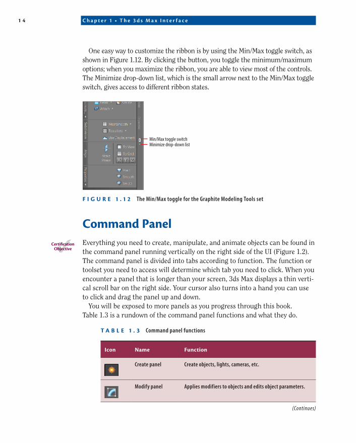
One easy way to customize the ribbon is by using the Min/Max toggle switch, as shown in Figure 1.12. By clicking the button, you toggle the minimum/maximum options; when you maximize the ribbon, you are able to view most of the controls. The Minimize drop-down list, which is the small arrow next to the Min/Max toggle switch, gives access to different ribbon states.
Min/Max toggle switchMinimize drop-down list
F I g u r e 1 . 1 2 The Min/Max toggle for the Graphite Modeling Tools set
Command panelEverything you need to create, manipulate, and animate objects can be found in the command panel running vertically on the right side of the UI (Figure 1.2). The command panel is divided into tabs according to function. The function or toolset you need to access will determine which tab you need to click. When you encounter a panel that is longer than your screen, 3ds Max displays a thin verti-cal scroll bar on the right side. Your cursor also turns into a hand you can use to click and drag the panel up and down.
You will be exposed to more panels as you progress through this book. Table 1.3 is a rundown of the command panel functions and what they do.
t a b l e 1 . 3 Command panel functions
Icon Name Function
Create panel Create objects, lights, cameras, etc.
Modify panel Applies modifiers to objects and edits object parameters.
CertificationObjective
(Continues)
C o m m a n d P a n e l 1 5
c01.indd 24-05-2014 07:27 PM
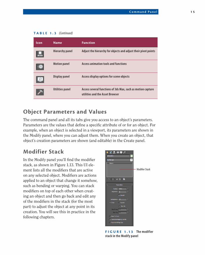
Icon Name Function
Hierarchy panel Adjust the hierarchy for objects and adjust their pivot points
Motion panel Access animation tools and functions
Display panel Access display options for scene objects
Utilities panel Access several functions of 3ds Max, such as motion capture
utilities and the Asset Browser
Object parameters and ValuesThe command panel and all its tabs give you access to an object’s parameters. Parameters are the values that define a specific attribute of or for an object. For example, when an object is selected in a viewport, its parameters are shown in the Modify panel, where you can adjust them. When you create an object, that object’s creation parameters are shown (and editable) in the Create panel.
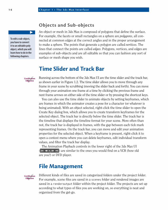
Modifier StackIn the Modify panel you’ll find the modifier stack, as shown in Figure 1.13. This UI ele-ment lists all the modifiers that are active on any selected object. Modifiers are actions applied to an object that change it somehow, such as bending or warping. You can stack modifiers on top of each other when creat-ing an object and then go back and edit any of the modifiers in the stack (for the most part) to adjust the object at any point in its creation. You will see this in practice in the following chapters.
t a b l e 1 . 3 (Continued)
Modi�er Stack
F I g u r e 1 . 1 3 The modifier stack in the Modify panel
1 6 C h a p t e r 1 • T h e 3 d s M a x I n t e r f a c e
c01.indd 24-05-2014 07:27 PM
Objects and Sub-objectsAn object or mesh in 3ds Max is composed of polygons that define the surface. For example, the facets or small rectangles on a sphere are polygons, all con-nected at common edges at the correct angles and in the proper arrangement to make a sphere. The points that generate a polygon are called vertices. The lines that connect the points are called edges. Polygons, vertices, and edges are examples of sub-objects and are all editable so that you can fashion any sort of surface or mesh shape you wish.
time Slider and track barRunning across the bottom of the 3ds Max UI are the time slider and the track bar, as shown earlier in Figure 1.2. The time slider allows you to move through any frame in your scene by scrubbing (moving the slider back and forth). You can move through your animation one frame at a time by clicking the previous frame and next frame arrows on either side of the time slider or by pressing the shortcut keys.
You can also use the time slider to animate objects by setting keyframes, which are frames in which the animator creates a pose for a character (or whatever is being animated). With an object selected, right-click the time slider to open the Create Key dialog box, which allows you to create transform keyframes for the selected object. The track bar is directly below the time slider. The track bar is the timeline that displays the timeline format for your scene. More often than not, the track bar is displayed in frames, with the gap between each tick mark representing frames. On the track bar, you can move and edit your animation properties for the selected object. When a keyframe is present, right-click it to open a context menu where you can delete keyframes, edit individual transform values, and filter the track bar display.
The Animation Playback controls in the lower right of the 3ds Max UI ( ) are similar to the ones you would find on a VCR (how old are you?) or DVD player.
File ManagementDifferent kinds of files are saved in categorized folders under the project folder. For example, scene files are saved in a scenes folder and rendered images are saved in a renderoutput folder within the project folder. The projects are set up according to what types of files you are working on, so everything is neat and organized from the get-go.
▶
To edit a sub-object, you have to convert it to an editable poly object, which you will learn how to do in the following chapters.
CertificationObjective
CertificationObjective
F i l e M a n a g e m e n t 1 7
c01.indd 24-05-2014 07:27 PM
The conventions followed in this book and on the accompanying web page (www.sybex.com/go/3dsmax2015essentials) follow this project-based system so that you can grow accustomed to it and make it a part of your own workflow. It pays to stay organized.
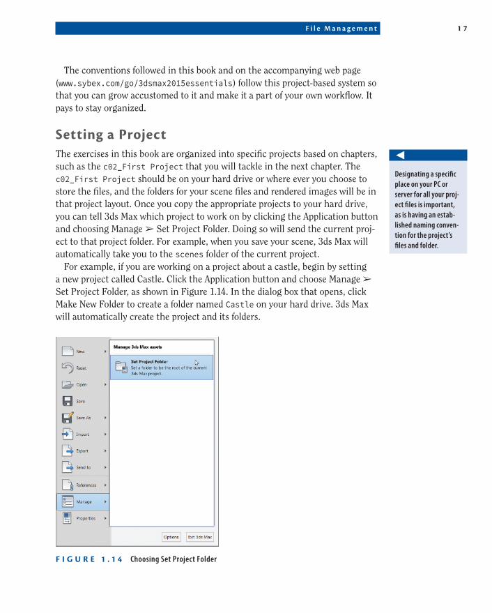
Setting a projectThe exercises in this book are organized into specific projects based on chapters, such as the c02_First Project that you will tackle in the next chapter. The c02_First Project should be on your hard drive or where ever you choose to store the files, and the folders for your scene files and rendered images will be in that project layout. Once you copy the appropriate projects to your hard drive, you can tell 3ds Max which project to work on by clicking the Application button and choosing Manage ➢ Set Project Folder. Doing so will send the current proj-ect to that project folder. For example, when you save your scene, 3ds Max will automatically take you to the scenes folder of the current project.
For example, if you are working on a project about a castle, begin by setting a new project called Castle. Click the Application button and choose Manage ➢ Set Project Folder, as shown in Figure 1.14. In the dialog box that opens, click Make New Folder to create a folder named Castle on your hard drive. 3ds Max will automatically create the project and its folders.
F I g u r e 1 . 1 4 Choosing Set Project Folder
◀
Designating a specific place on your PC or server for all your proj-ect files is important, as is having an estab-lished naming conven-tion for the project’s files and folder.
1 8 C h a p t e r 1 • T h e 3 d s M a x I n t e r f a c e
c01.indd 24-05-2014 07:27 PM
Once you save a scene, one of your scene filenames may look like this: c02_ex3_body_v01.max. This tells you right away it’s a scene from Chapter 2, exercise 3, and that it is version 1 of the model of the body.
Version up!After you’ve spent a significant amount of time working on your scene, you will want to version up. This means you save your file using the same name, but you increase the version number by 1. Saving often and using version numbers are useful for keeping track of your progress and protecting yourself from mistakes and from losing your work.
To version up, you can save by clicking the Application button, choosing Save As, and manually changing the version number appended to the end of the file-name. 3ds Max also lets you do this automatically by using an increment feature in the Save As dialog box. Name your scene file and click the Increment button (the + icon) to the right of the File Name input field. Clicking the Increment button appends the filename with 01, then 02, then 03, and so on as you keep saving your work using Save As and the Increment button.
Now You Know
In this chapter, you learned the basic operation of the 3D workspace and user interface, start-ing with a tour of the UI and getting initial experience manipulating an object using 3ds Max Transform gizmos. Then you saw how to access the Graphite Modeling Tools set and how to control your scene with the command panel. Next, you learned how the time slider and track bar work, and lastly, you saw how to best manage files for a clean workflow using projects.
As you continue with the following chapters, you will gain experience and confidence with the UI, and many of the features that seem daunting to you now will become second nature. Meanwhile, use this chapter as a reference to help you navigate the UI as you progress in your knowledge of the 3ds Max workflow.