the aar standard for a spill-proof locomotive …...the aar standard for a spill-proof locomotive...
TRANSCRIPT
THE AAR STANDARD FOR A SPILL-PROOF LOCOMOTIVE REFUELING SYSTEM
Christopher P.L. Barkan Associate Professor
Director - AAR Affiliated Laboratory University of Illinois at Urbana-Champaign
1201 Newmark Civil Engineering Laboratory 205 N. Mathews Ave., Urbana, IL 61801
Tel: (217) 244-6338 • Fax: (217) 333-1924 [email protected]
Preston Sargent
Manager - Mechanical Systems Design (retired) Union Pacific Railroad
current address Sargent Technology
P.O. Box 415 Malvern, IA 51551 Tel: (712) 624-9807
ABSTRACT The Association of American Railroads (AAR) has recently completed development of the first industry standard for a reliable, spill-proof locomotive refueling system. The Locomotive Fueling Interface Standard (LFIS) is an open, non-proprietary standard that incorporates a combination of the latest, proven refueling equipment technologies adapted for use in the railroad environment. The LFIS was developed with extensive oversight and involvement by a multi-disciplinary task force composed of individuals from railroads' mechanical, environmental, transportation and fuel purchasing groups, along with refueling equipment suppliers that supply the railroad, aircraft, mining, and cargo tank truck industries. Prototype equipment was successfully tested at the Transportation Technology Center in 1998 and then underwent field-testing on seven North American railroads at nine different locations over a period of 22 months. Following successful completion of the field-testing in 2000 the LFIS was adopted by the AAR as a recommended practice in early 2001. A cost:benefit analysis indicates that the reduction in energy and environmental costs that railroads will accrue with adoption of the LFIS will pay for the LFIS equipment in 1 to 3 years. Adoption of the LFIS is a cost-effective means for most North American railroads to prevent spillage and improve refueling performance. INTRODUCTION Fuel spillage during locomotive refueling is a major expense for North American railroads, with an annual estimated cost of $48.9 million. For a variety of reasons that became increasingly evident in the early 1990s, the lack of an industry standard for refueling equipment was contributing to the incidence of this spillage. Consequently, in
1996, the AAR Environmental Affairs Committee and the AAR Locomotive Committee jointly proposed that the AAR develop an industry standard for a reliable, spill-proof locomotive refueling system. This proposal was accepted and approved by senior AAR committees and the Locomotive Fueling System Task Force (LFSTF) was formed to provide oversight to AAR for the standard development process. The need for a standard for locomotive refueling The concept of standardization is fundamentally important to many aspects of efficient railroad design and operation. Standardized designs are beneficial because they, enable manufacturers and their customers to take greater advantage of economies of scale in production thereby lowering cost, reduce the inventory of replacement parts needed, reduce the diversity in maintenance and repair procedures and equipment required, and simplify employee training. For railroads interchanging equipment, the benefits are leveraged across all of the companies, and where interoperability is required, they are essential. Conversely, standardization for its own sake is not necessarily desirable. The "one-size-fits-all" aspect of standardization may not be optimal for the particular circumstances in which a standard is employed. The benefit of the standard may be more than offset by the suboptimal application.
Railroad dieselization led to a need for a system to efficiently deliver fuel to
locomotives. In its simplest form a hose with a pipe at the end would suffice. The desire to use locomotive servicing personnel efficiently while avoiding spillage due to tank over-filling, led to early development of automatic shut-off systems for locomotive refueling. By the 1950s several systems were available (1), but no industry-standard for the fittings or shut-off technology was developed.
Initially, the motivation for automatic fuel shut-off systems was to avoid waste.
Beginning in the 1970s, as regulations to prevent water pollution came into effect, environmental protection also became a factor. Over the past four decades, various manufacturers' new or updated locomotive refueling systems were introduced to the railroad industry. By the late 1980s all of the major US and Canadian railroads were using one of four different systems then on the market.
Current Locomotive Refueling Systems The refueling systems in general use by North American railroads are reliable when properly operated and maintained (2). However, these systems are subject to several types of malfunctions if not regularly maintained. Since the designs are not generally fail safe, a malfunction in the automatic shut-off system can lead to a spill due to overfilling. Conversely, improperly functioning systems are susceptible to premature shutoff. When this occurs, busy refueling personnel may override the automatic shut-off system, which can also lead to overfilling. Since most refueling takes place over spill collection systems, there is generally no release to the environment. However, the expense of the spilled fuel and the cost of the resultant waste treatment and disposal are incurred. If any spilled fuel were to reach the environment, it will lead to additional risk and expense.

Another aspect of the refueling systems in use in the mid-1990s that was unsatisfactory to railroads was that they were proprietary designs. Only the manufacturer of the each system could provide most replacement parts. And because the automatic shut-off technology for each of the systems differed, they were incompatible with one another. When a locomotive equipped with one type of system was refueled at a wayside location equipped with another type of system, an adapter fitting was required that rendered the automatic shut-off feature inoperable. As long as railroads primarily refueled their own locomotives the compatibility issue was not an operational problem.
What was a problem was that if a railroad desired to change suppliers it could
not easily phase out previously deployed equipment through attrition. Instead it had to change out all of the equipment on its locomotives and wayside fueling facilities. This was not only costly but also troublesome during the transition period because of the incompatibility between the old and new equipment. When such changes were made, some railroads chose to endure an extended period of inconvenience and inefficiency. Alternatively, some railroads used a "blitz" approach to the change out, but this had its own financial and logistic difficulties.
A system in which changes in supplier did not require the removal of currently
deployed equipment was much more attractive to railroads. It would facilitate competitive bidding for new and replacement equipment, thereby allowing railroads to take greater advantage of the performance and cost benefits of competition, it would allow railroads to retain current equipment until it had reached the end of its service life and it would not create operational problems as new equipment was used with old. Changes in Locomotive Fueling Although the above-described disadvantages of reliability and compatibility had been in place from the inception of automatic shut-off locomotive refueling systems, apparently they had not posed a sufficient problem for the industry to take steps to overcome them. However, in the late 1980s and early 1990s three factors changed that tipped the balance toward consideration of new approach.
1) Railroads were increasingly using run-through, pooled and leased power, leading to more frequent refueling of locomotives at other railroads' facilities.
2) EPA promulgated new regulations that pertained to stormwater runoff at railroad
refueling facilities (3). This raised the imperative to find a cost-effective means of preventing fuel spillage, rather than relying on the traditional method of containment and treatment of fuel-contaminated wastewater.
3) Railroads increasingly began to take advantage of the operational and reduced
infrastructure benefits of direct truck to locomotive (DTL) fueling as compared to fixed facilities (2, 4). The third factor interacts with the second because most DTL fueling sites are, by
their nature, transitory and do not generally have spill collection and containment
equipment in place. For the same reason, these sites tend not to have platforms for refueling personnel to stand on, or apparatus to support the fueling equipment. A survey of the major railroads found that as of the mid 1990s, approximately 75% of the locomotive sites in North American were DTL (2). Although these sites accounted for only about 10% of the fuel issued, the cost to equip them with spill collection equipment would be prohibitive, and impractical because of their transience. Under these circumstances the vigilance of the refueling personnel is the only protection from a malfunctioning automatic shut-off system.
Fuel spillage costs railroads twice
The lost value of the spilled fuel can be substantial and the near doubling in fuel
price over the past 2 1/2 years (AAR unpublished data) has made this aspect considerably more important. However the second cost, collection and treatment of wastewater contaminated with spilled fuel, is even greater. Environmental regulations generally require that spilled fuel not impact the environment. Consequently, extensive collection and treatment equipment is often installed and personnel employed to operate, maintain and manage the system and ensure environmental compliance. When all of these capital and operating costs are accounted for, they may be as much as 10 times higher than the cost of the fuel itself. This is consistent with unpublished AAR data that indicate that the first and third largest items in North American railroads' environmental budgets are cleanup of petroleum-contaminated soil and wastewater treatment. The cost of both of these items is largely driven by past and present fuel spillage.
LOCOMOTIVE FUELING INTERFACE STANDARD The AAR and its members decided to address both unreliability and incompatibility in automatic fueling systems by developing an open, industry standard for a reliable, spill-proof refueling and automatic shut-off system. Railroads wanted the new Locomotive Fueling Interface Standard (LFIS) to be an open standard, to take advantage of advances in refueling technology and be designed to meet current and future requirements for locomotive refueling.
To ensure that the perspectives of all the "stakeholders" in the locomotive
refueling process were considered, the AAR formed a multi-disciplinary task force to oversee development of the new standard. The major North American railroads participated and representation specifically included a balance of individuals from railroad mechanical, environmental, transportation, and fuel purchasing groups. Refueling equipment manufacturers, including those currently supplying railroads and other transport modes also participated. Each of the groups represented on the Locomotive Fueling Standard Task Force (LFSTF) had particular objectives that they wanted the new standard to achieve.
The first step in this process was to develop a "statement of need" (SON). The
railroads identified all of the objectives they wished to achieve with the new standard. These were documented in the SON, which was then provided to refueling equipment manufacturers for their review and comment regarding both the technical and economic
implications of various options. The whole group then met again and discussed each of the objectives and the pros and cons of various approaches and developed a consensus on the final content of the SON. This served as the reference document for the subsequent development of the details of the LFIS.
Refueling Technology Review In order to develop a better understanding of the factors contributing to fuel spillage, an analysis of railroad refueling practices and equipment was conducted by AAR (2, 3). This provided information on the strengths and weaknesses of current systems and the difficulties and problems in the railroad-operating environment that would have to be overcome.
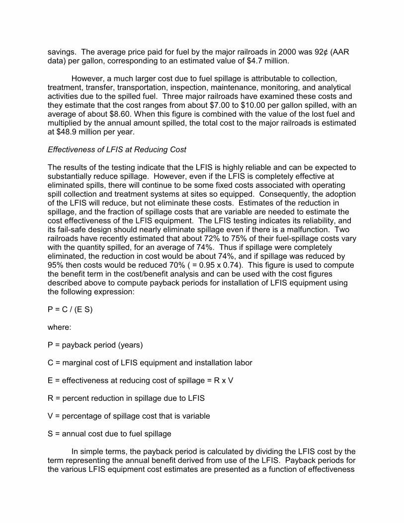
In addition to the review of railroad systems, the LFSTF also examined refueling
systems used by other modes, with particular attention paid to commercial aircraft and the American Petroleum Institute (API) recommended practice for cargo tank trucks (5). It was evident that despite the large quantity of fuel transferred, these operations experienced considerably less spillage than was typical for railroads. Taken individually, each of the other systems had advantages and disadvantages for railroad application so the task force chose to adapt the best combination of proven features for the new railroad standard (Table 1).
One of the decisions the railroads had to make was whether the shut-off valve
should be on or off the locomotive. On commercial aircraft the control valve is onboard. The advantage of this system is that it eliminates the requirement that a high-level shut-off signal be transmitted to the wayside. The low reliability of this signal is a principal reason for spillage in railroad refueling. The disadvantage is that it increases the cost and complexity of the locomotive components. There are approximately seven times as many locomotives as there are fueling locations on the major North American railroads (ca. 23,000 compared to 3,300) (2). Furthermore, each locomotive would require a valve on both sides so every unit of cost increase on the locomotive-mounted components would have a 14-times greater impact on system cost than a comparable increase in wayside equipment. Because locomotives are constantly on the move, the repair of the on-board components is more difficult and maintenance opportunities less frequent than for wayside components. The shock and vibration environment is also considerably more aggressive on the locomotive than on the wayside. Consequently, locomotive components must be sufficiently robust to maintain highly reliable performance under harsh conditions and infrequent maintenance. Taken together these factors led the task force to opt for an off-board shut-off system and to strive for simplicity and reliability in the on-board components and shut-off signal. Evidence for the feasibility of this approach could be found in the success of the automatic shut-off system used in the API standard for cargo tanks (5)
The basic architecture of the LFIS is shown in Figure 1 (6). The railroads wanted
high performance in the important functions of the new fueling system standard, but they also desired flexibility for themselves and suppliers in achieving that performance. Consequently, wherever possible the standard specifies performance rather than design. The principal exception to this is at the interface between the locomotive and
the wayside. In this case, because of the requirement for a physical connection, the geometry of the connections had to be specified in order to assure that components would inter-operate properly, irrespective of manufacturer or model. Also, the general parameters of the signal used to indicate high fuel level had to be specified, although the standard allows for a range of operation within these parameters.
By combining the information on causes of railroad fuel spillage with knowledge
of the features available in refueling equipment, the task force developed a matrix (Table 2) that showed which features would provide solutions to the problems railroads experienced.
Key spill-prevention features of the LFIS
1) An open standard design for the interface between the locomotive and the wayside,
thereby preventing problems with incompatible fueling systems. 2) A dry disconnect/positive interlock coupling that almost completely prevents spillage
from the nozzle or the fuel tank receptacle. The LFIS requires the dry disconnect feature to limit the amount that can be spilled to no more than 5 ml. when the nozzle is disconnected. The positive interlock prevents the nozzle from being opened until it is securely locked onto the fuel tank receptacle, thereby preventing fuel from being issued under any other circumstances. The dry disconnect/positive interlock feature will also prevent fuel from being forced out of the receptacle when the nozzle is removed from a fuel tank that has become pressurized. This condition, sometimes called "blowback", is a problem for railroads operating in cold climates because it occurs when the fuel tank vent becomes clogged with snow and ice.
3) A robust, low voltage (and "inherently safe"), electrical signal for communicating
fuel-level information from the locomotive to the wayside shut-off system provides a highly reliable shut-off signal when the tank is full. The task force evaluated all the systems currently available for this function and determined that an electrical connection offered the best combination of high reliability and low cost. An important attribute of the electronic signal in this application is its high signal to noise ratio that nearly eliminates the possibilities of "false positives" or "true negatives" in the shut-off signal. The electronic system also incorporates a diagnostic test to continuously assess the health of the high level sensor and the associated circuitry when in use. It is "fail safe" so if there is a malfunction anywhere in the control or sensor system, fuel flow is terminated.
4) An override mode that requires regular, active attention by refueling personnel. The
task force recognized that circumstances could occur in which the automatic shut-off might have to be overridden. When this occurs, the task force wanted to ensure that fueling personnel must remain nearby the fueling stanchion to guard against overfilling. This is accomplished by a feature in the control electronics that requires the fueling operator to frequently refresh the permissive signal by pushing a button attached to the controller in order for fuel to continue flowing while in override mode.

5) Although not a mandatory element, the LFIS is capable of supporting a pressure-sensor-actuated shutoff. This allows railroads to use internal fuel tank pressure to actuate shutoff in addition to high fuel level. This will prevent pressurization of the tank that can occur if the fuel tank vent becomes clogged. For railroads operating in cold climates this option can prevent tank rupture and the resultant spillage, as well as avoid the repair and locomotive out-of-service time costs. Combined with the dry-disconnect feature, it can also avoid the condition that leads to blowback described above.
In addition to the spill-prevention related requirements, the railroads viewed the
development of the new standard as an opportunity to improve other aspects of locomotive refueling operation, performance and economics. Consequently they specified that the LFIS, be durable, have minimal maintenance requirements, support higher fuel delivery rate, support fuel management information transfer, and employ a lightweight, easy-to-use nozzle design that would function well in a variety of DTL conditions. And above all else, the standard was to be an open, nonproprietary design so railroads could take full advantage of the benefits of competition in the refueling equipment market. Principal Components of the LFIS
Fluid transfer
1) The receptacle is the fitting mounted on the locomotive tank that receives fuel. The
geometry of the receptacle is precisely defined in the LFIS (Figure 2) and includes a requirement for a poppet valve that remains closed at all times unless it is properly connected to an LFIS compliant nozzle.
2) The nozzle provides the mechanical interface between the wayside fuel supply line
and the receptacle. It is connected by a push-on motion and then locked in place by a mechanism that is interlocked to open the poppet valves on the nozzle and receptacle at the same time. The reverse action closes the poppets and releases the nozzle. The LFIS requires that the nozzle be lightweight and specifies several other aspects of its ease and safety of use under realistic operating conditions.
3) The LFIS does not specify the fuel shut-off device, but for the system to function,
there must be some means of halting fuel flow when the wayside controller receives the high level signal. An electrically controlled valve and/or pump shutoff would typically be used for this and the LFIS contains some recommendations for these.
Level sensing, automatic shut-off signal and control 4) The high level sensor and signal processor unit is mounted on the locomotive. The
signal processor receives the input signal from the wayside controller via the socket and plug connection (see below) and the sensor detects when the fuel tank is full. When the tank is not full and the sensor is receiving a proper signal from the controller, a "permissive" signal is returned to the controller permitting fuel to flow. If the fuel level is at or above the sensor, or if there is any malfunction in the sensor

system, it generates a "nonpermissive" condition within 0.25 seconds that halts fuel flow. The LFIS requires that the permissive signal received from the controller be modified within certain parameters from the input signal before it is returned to the wayside controller. This prevents someone from simply shunting the circuit on the wayside and enabling fuel flow without the high level sensor in the circuit.
5) The socket and plug, on the locomotive and wayside respectively, use a multiple pin
system to connect the on-board, high-level, sensor with the wayside controller (Figure 2). It is a modified version of the design used by API RP-1004 which is a rugged system successfully used for similar applications in the cargo tank truck industry for decades. The primary modification was the addition of additional pin connectors to support the option for transfer of fuel management information desired by railroads.
6) The wayside controller provides the primary control circuitry that communicates with
the high-level sensor on the locomotive, and controls the fuel shut-off device on the wayside. It provides the input signal to the high level sensor and responds appropriately to the permissive or nonpermissive signal it receives back. The LFIS requires that the controller be capable of both amplitude and pulse width discrimination, two commonly used systems for indicating the permissive condition. Although diesel fuel is not one of the substances referenced in the National Electrical Code (NEC) the task force elected to require that all circuitry on, and connecting to the locomotive, conform to NEC requirements for intrinsic safety. The LFIS also requires that the controller work in both fixed facility and DTL settings.
Development and Testing The major work of developing the LFIS took place through a series of meetings, teleconferences, analyses, reports, and correspondence during 1997. In early 1998 a draft specification was ready and five manufacturers constructed prototype LFIS equipment for testing on locomotives operating at the Facility for Accelerated Service Testing at the Transportation Technology Center. These tests were successful and suggested a few minor modifications that were incorporated in the next draft standard.
The next phase in the testing was to install LFIS equipment at railroad refueling
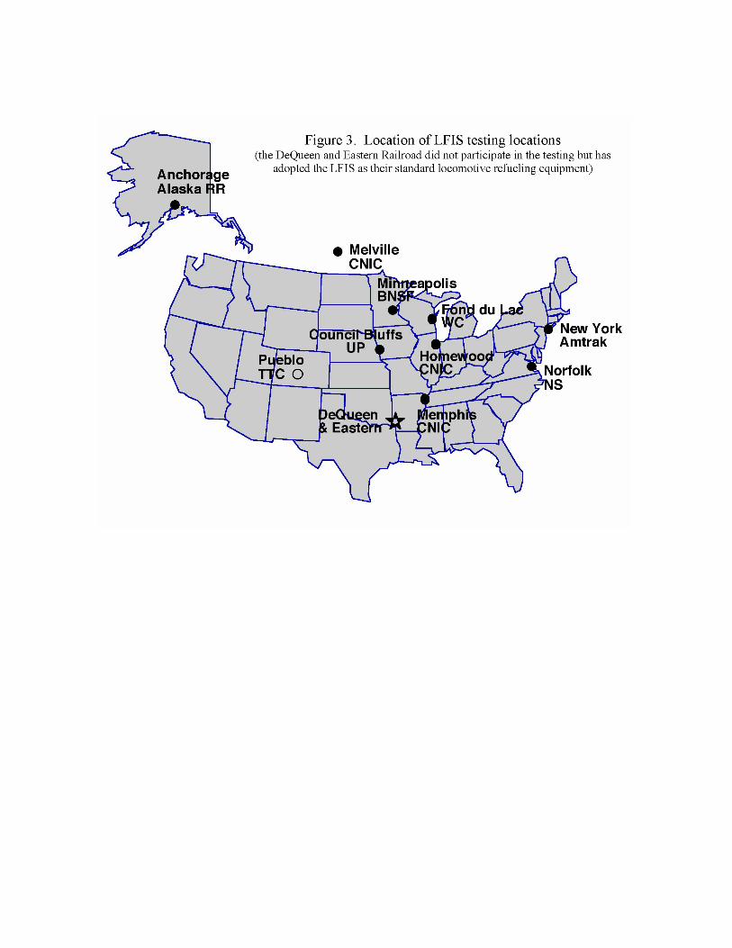
sites. Practical issues regarding refueling equipment compatibility, training of refueling personnel, and data collection efficiency dictated that the sites be locations with "captive" locomotives that always refueled at the same location. A second, larger group of prototype equipment was then constructed and installed at the selected sites. The first railroad began field-testing in early 1999 and equipment was successively deployed at various new sites for the next 12 months. In total the field-testing extended over a 22-month span and involved nine different fueling sites on seven railroads (CN and IC completed their merger during the test) (Figure 3). A total of 768 refuelings using LFIS equipment took place during the field-testing.
Each time a locomotive was refueled using the LFIS equipment a standard
reporting form was completed by the refueling personnel who recorded information on when, where and who did the fueling, along with information on performance. The
forms were faxed to AAR where a weekly summary was prepared and distributed to all of the railroads and suppliers participating in the testing. This process served the dual objectives of allowing railroads and manufacturers to benefit from one another’s experience, and gathering information on the possible need for further refinement of the standard. A benefit of staggering the test startup dates for different sites was that it allowed railroads and suppliers to learn from the preceding installations.
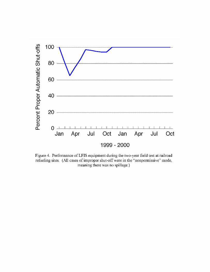
The results of these tests indicated little need for changes in the LFIS itself.
They did highlight the need for more initial training in use of the equipment at certain locations and that some of the prototype equipment was not fully compliant with certain requirements of the standard. Figure 4 shows the percentage of successful automatic shutoffs over the period of the field-testing. Because of the fail-safe requirements of the LFIS, none of the unsuccessful automatic shutoffs resulted in a spill. They indicate circumstances when the operator believed that the automatic shutoff had been premature. In some cases this was correct because of the aforementioned equipment problems and in others, it was a misunderstanding by the operator on the proper functioning of the equipment on a particular locomotive. The AAR information exchange process quickly drew attention to these problems and they were corrected as evidenced by the 100% reliable performance during the final 12 months of the test, that included the last four LFIS installations, none of which experienced any failures. COST EFFECTIVENESS The results of testing indicated that the LFIS is an effective system for reliable, spill-proof refueling of locomotives. However, if railroads are to adopt it, it must be also be cost-effective. Calculation of cost-effectiveness requires data on the benefits and costs of the LFIS. The principal monetary benefit is derived from the spillage that would be prevented and the corresponding savings. There may be other benefits related to the higher refueling rate and other positive attributes of the LFIS; however, these are not included in the analysis presented here. The principal cost is the marginal expense for purchase and installation of the new equipment compared to continued use of current equipment.
The cost:benefit analysis presented here includes data for the US Class 1
railroads, the two major Canadian railroads (including their US properties), and Amtrak. Figures for other North American railroads are not included; however, it is reasonable to assume that taken as a whole, these other railroads' figures for fuel consumption, spillage, and equipment requirements are generally proportional and therefore would not substantially change the cost:benefit ratio of the results. Computation of Industry Costs LFIS Component Costs The costs for LFIS installation were developed by surveying LFIS component suppliers and should be considered "list" prices (as of 2000). Suppliers provided two price estimates for each of the major components based on an assumption of a small and a large quantity purchase of each component. The figures provided for each component

were used to compute an average low and high cost and an overall average (Table 3). The LFIS does not include specification requirements for the wayside control valve, but this is an essential component of the system so cost estimates for it are included in the analysis as well.
Installation Labor Costs The installation costs are based on low, intermediate and high estimates of installation time derived from experience gained during the LFIS testing. A railroad that adopted a large-scale LFIS installation program would quickly develop efficient routines that might be quicker than the figures here. Labor costs are based on 1999 AAR data on average railroad equipment maintenance personnel wages of approximately $43,000 per year (7), plus 30 percent for fringe benefits, which results in an hourly rate of $27.00. These labor costs are approximate, but sensitivity analyses of this portion of the cost:benefit analysis indicate that the results are not strongly affected by them. For example, doubling the labor cost would increase the payback time by only 15 percent. Estimate of Industry Cost of LFIS Equipment The estimated industry cost to install LFIS equipment was computed by multiplying the wayside and locomotive costs by the number of fueling stanchions and the locomotive fleet size (Table 3). During a transition period from the current fueling equipment to LFIS equipment, some new locomotives would be purchased. These locomotives would have to be equipped with new fueling equipment anyway. Consequently only the difference in the cost of the current equipment compared to the cost of LFIS equipment should be accounted for in the benefit/cost analysis. During the 5-year period 1995 through 1999 an average of 4% new locomotives were added to the Class 1 rosters (7). If the transition period to the LFIS extended over 3 years, then the 4% annual replacement rate and the fleet estimate of 23,000 locomotives, translates to about 2,700 locomotives. If the current equipment costs $500 per locomotive, then this amount multiplied by 2,700 equals $1.4 million that would have been spent anyway and should be subtracted from the estimated cost of changing to the LFIS. The analysis assumes that all of the remaining 23,000 locomotives would be retrofitted with LFIS compliant equipment. Computation of Industry Benefits The capability of the different major US and Canadian railroads to track fuel spillage varies. This capability also varies for different sites depending on the collection and monitoring systems in place. At most direct truck to locomotive (DTL) fueling sites there is almost no ability to quantify spillage whereas at many fixed facilities, fairly detailed information is available. Five major railroads were able to provide company-wide data on fuel spillage rates. The average was 0.12 percent of the fuel issued. This statistic can be used to estimate the total fuel spilled by the railroads in this analysis. In 1999 the major railroads issued about 4.4 billion gallons. Using the spill rate above, this corresponds to an annual volume spilled of 5.1 million gallons. The principal direct benefit that will accrue to railroads if the LFIS is adopted is a reduction in fuel spillage and its associated costs. The value of the lost fuel is an important part of the potential
savings. The average price paid for fuel by the major railroads in 2000 was 92¢ (AAR data) per gallon, corresponding to an estimated value of $4.7 million.
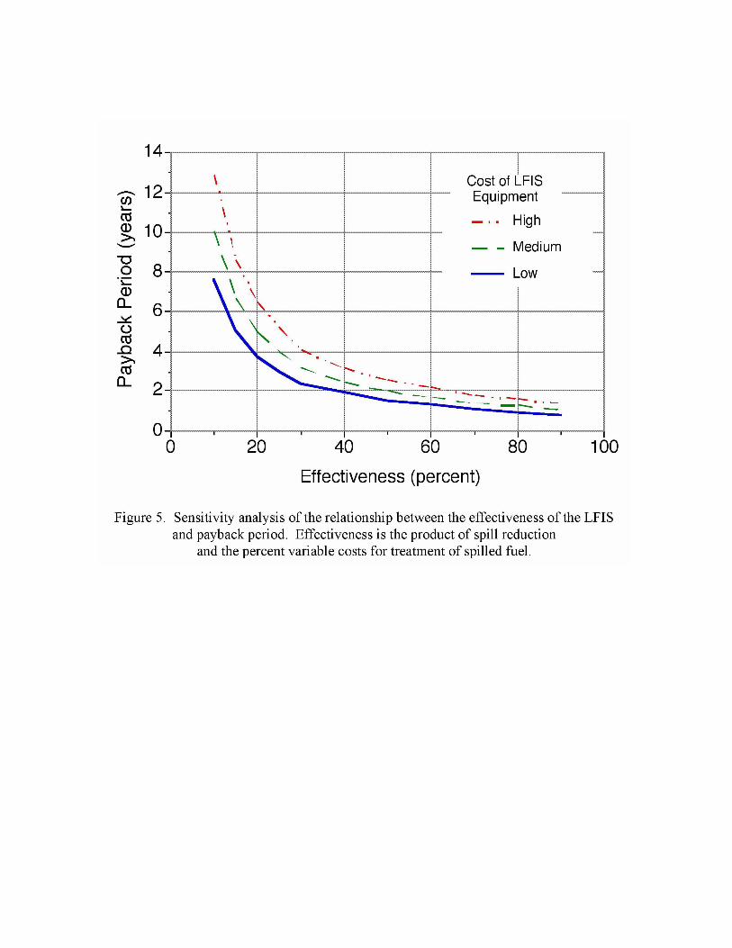
However, a much larger cost due to fuel spillage is attributable to collection, treatment, transfer, transportation, inspection, maintenance, monitoring, and analytical activities due to the spilled fuel. Three major railroads have examined these costs and they estimate that the cost ranges from about $7.00 to $10.00 per gallon spilled, with an average of about $8.60. When this figure is combined with the value of the lost fuel and multiplied by the annual amount spilled, the total cost to the major railroads is estimated at $48.9 million per year. Effectiveness of LFIS at Reducing Cost The results of the testing indicate that the LFIS is highly reliable and can be expected to substantially reduce spillage. However, even if the LFIS is completely effective at eliminated spills, there will continue to be some fixed costs associated with operating spill collection and treatment systems at sites so equipped. Consequently, the adoption of the LFIS will reduce, but not eliminate these costs. Estimates of the reduction in spillage, and the fraction of spillage costs that are variable are needed to estimate the cost effectiveness of the LFIS equipment. The LFIS testing indicates its reliability, and its fail-safe design should nearly eliminate spillage even if there is a malfunction. Two railroads have recently estimated that about 72% to 75% of their fuel-spillage costs vary with the quantity spilled, for an average of 74%. Thus if spillage were completely eliminated, the reduction in cost would be about 74%, and if spillage was reduced by 95% then costs would be reduced 70% ( = 0.95 x 0.74). This figure is used to compute the benefit term in the cost/benefit analysis and can be used with the cost figures described above to compute payback periods for installation of LFIS equipment using the following expression: P = C / (E S) where: P = payback period (years) C = marginal cost of LFIS equipment and installation labor E = effectiveness at reducing cost of spillage = R x V R = percent reduction in spillage due to LFIS V = percentage of spillage cost that is variable S = annual cost due to fuel spillage
In simple terms, the payback period is calculated by dividing the LFIS cost by the term representing the annual benefit derived from use of the LFIS. Payback periods for the various LFIS equipment cost estimates are presented as a function of effectiveness

in Figure 5. Using the estimate of a 70% reduction in cost due to fuel spillage, the corresponding payback period ranges from 1.1 to 1.8 years, depending on the cost of the LFIS equipment. If this figure is typical for the industry, it suggests that adoption of the LFIS is likely to be acceptable using typical railroad procurement decision criteria. Even for effectiveness levels as low as 40%, the payback period is generally less than 3 years. However, figures for a particular railroad will vary depending upon the particular input values used for the cost benefit model. Other benefits of the LFIS Beyond the quantifiable economic benefits described above, there are a number of other factors that will also act to improve the railroads' benefit:cost ratio if the LFIS is adopted. They are not formally incorporated into the analysis but nevertheless some aspects of these can be expected to accrue to railroads that adopt the standard. Cost Reduction Pressures on LFIS Components Because the LFIS is an open standard it is reasonable to expect competitive pressures for lower price and higher quality thereby improving value to railroads. Investment in one manufacturer's system will not create "inertia" to continue using that manufacturer's products if the equipment does not meet the railroad's performance or replacement price requirements. Procurements of new refueling equipment can be bid competitively with assurance that it will be compatible with other manufacturers' equipment already in place.
Refueling equipment manufacturers have shown strong interest and support for
the LFIS. At least seven manufacturers are offering components compliant with LFIS requirements (Carcon, Emco Wheaton, FloTech, Noverflo/Midland, Optima, Scully, and TransDigm). Railroads can benefit from the economies of scale associated with supplying a standard design. Furthermore, many of the components used in the LFIS are similar or identical to items used in other refueling applications outside the railroad industry. In this respect, the 23,000 North American locomotives are a substantial addition to the estimated 30,000 to 40,000 cargo tank trailers in use. Furthermore, railroads outside of North America have begun to adopt the AAR LFIS, further enlarging the market for components. Environmental Protection, Compliance Costs and Operating Flexibility Adoption of the LFIS can be touted by the railroads as a "best available technology" for fuel-spill prevention thereby helping to stave off more costly regulatory requirements for spill collection and treatment systems at refueling facilities. This will allow railroad transportation departments more flexibility regarding when and where DTL fueling is used. Ease of Use by Refueling Personnel

The light weight of the nozzle will help reduce the likelihood of worker injury when connecting or disconnecting. The LFIS will also prevent "blowback", another potential source of worker injury. Higher Refueling Productivity Tests of the LFIS have demonstrated that it permits higher refueling rates (50% or better) even with existing pumping systems. This will enable faster refueling and thus higher productivity at refueling facilities and more rapid turnaround of locomotives. The high reliability of the LFIS will free up refueling personnel for other duties associated with locomotive fueling facilities, also improving productivity. Reduced Refueling Maintenance and Inventory Costs The LFIS components are simple in design and have few moving parts. The LFIS was explicitly designed to require only a small amount of maintenance requiring simple tools and skills. Because the nozzle is simpler in design than some of the designs currently in use, the spare nozzle inventory and periodic rebuilding costs can also be reduced. Fuel Management and Locomotive Health Although not an immediate benefit, the LFIS was designed to support the electronic transfer of information for fuel management at fueling facilities. If railroads want to employ this technology to improve their operations, the LFIS components are capable of supporting the requisite data transfer. Similarly, the extra electrical pin connections available in the LFIS could also be used to electronically transfer locomotive health information if a railroad wished. CONCLUSION The LFIS is an open, non-proprietary performance and design standard for a locomotive refueling system that was developed in response to changes in railroad refueling requirements that have occurred in the past 10 to 15 years. It was a collaborative development effort by railroads and refueling equipment manufacturers who evaluated current problems and future demands for locomotive refueling and developed a new standard that addresses the needs using proven technologies. Tests of the system showed that the system was practical, robust and reliable in field operation by railroads. A cost benefit analysis indicates that for most railroads, the LFIS is a cost-effective means of reducing fuel spillage and improving refueling performance. ACKNOWLEDGMENTS The development of the LFIS was a collaborative effort. The authors were privileged to have had such a capable team in the membership of the Locomotive Fueling System Task Force, and the consulting firms that supported the LFSTF. Without the efforts of this talented and dedicated group of railroaders, refueling equipment manufacturers and consulting engineers, the development of the LFIS would not have been possible.

Direct funding for the project came from AAR's Research & Test and Safety & Operations programs. Additional support critical to the success was generously provided by refueling manufacturers who provided R&D that benefited development of the LFIS, and by the railroads that undertook considerable effort to conduct field-testing. REFERENCES CITED 1. Railway Track and Structures Cyclopedia, 8th Edition. 1955. Simmons-Boardman Publishing, New York, NY. 2. Brownlee, R.C. & C.P.L. Barkan 2001. Maintaining performance of automatic shut-off nozzles used for locomotive fueling. R-919. Association of American Railroads, Washington, DC. 3. Barkan, C., J. Waggener, & E. Hockensmith 1992. Treating storm water. Railway Track and Structures 88: 24-26, 39. 4. Barkan, C.P.L., R.C. Brownlee, and T.C. Borer 1996. Prevention of spillage during direct truck to locomotive fueling. TD 96-009. Association of American Railroads, Washington, DC. 5. Recommended Practice 1004 "Bottom loading and vapor recovery for MC-306 tank vehicles" American Petroleum Institute, Washington, DC. 6. Manual of Mechanical Standards and Recommended Practices, Section M Locomotive Fueling Interface Standard (in press). Association of American Railroads, Washington, DC (the 9th draft (current version) of the LFIS can also be downloaded at www.aar.org/lfis/lfis.htm ) 7. Association of American Railroads. Railroad Facts, 2000 Edition. Association of American Railroads, Washington, DC.
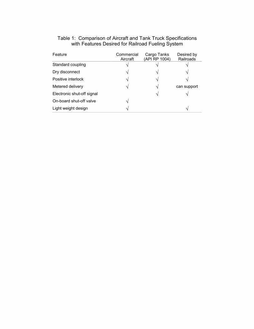
Table 1: Comparison of Aircraft and Tank Truck Specifications
with Features Desired for Railroad Fueling System
Feature CommercialAircraft
Cargo Tanks(API RP 1004)
Desired by Railroads
Standard coupling √ √ √ Dry disconnect √ √ √ Positive interlock √ √ √ Metered delivery √ √ can support
Electronic shut-off signal √ √ On-board shut-off valve √ Light weight design √ √
Table 2: How Features of Railroad Fueling System Address Principal Causes of Locomotive Fuel Spillage
Cause
Standard Interface
Dry
Disconnect
Positive Interlock
Reliable Shut-off Signal
System Health
Diagnostic
Active Override
Mode
Optional Pressure Sensor
Overfills Automatic Shut-off Failure √
incompatibility √ flow rate √ pressure √ √ loose connection √ √ operator override √ √ √
Uneven Cross-level √ √ Thermal Expansion √
Spillage at Disconnect √ √ Fuel Tank "Blowback" √ √ √ Fuel Tank Rupture √ Locomotive Rollover Accident √
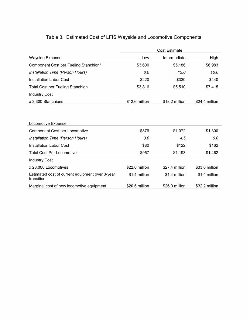
Table 3. Estimated Cost of LFIS Wayside and Locomotive Components
Cost Estimate
Wayside Expense Low Intermediate High
Component Cost per Fueling Stanchion* $3,600 $5,186 $6,983
Installation Time (Person Hours) 8.0 12.0 16.0
Installation Labor Cost $220 $330 $440
Total Cost per Fueling Stanchion $3,816 $5,510 $7,415
Industry Cost
x 3,300 Stanchions $12.6 million $18.2 million $24.4 million
Locomotive Expense
Component Cost per Locomotive $876 $1,072 $1,300
Installation Time (Person Hours) 3.0 4.5 6.0
Installation Labor Cost $80 $122 $162
Total Cost Per Locomotive $957 $1,193 $1,462
Industry Cost
x 23,000 Locomotives $22.0 million $27.4 million $33.6 million
Estimated cost of current equipment over 3-year transition
$1.4 million $1.4 million $1.4 million
Marginal cost of new locomotive equipment $20.6 million $26.0 million $32.2 million

Locomotive Interface Wayside
fuel linenozzle
fuelreceptacle
Figure 1. Schematic diagram of the basic Locomotive Fueling Interface Standard design. (Locomotive components are on the left and wayside components on the right.)

Figure 2 LFIS receptacle and plug