the adaptive secondary mir- venice 2001 ror for the 6.5m...
TRANSCRIPT

The adaptive secondary mir-ror for the 6.5m conversionof the Multiple Mirror Tele-scope
Venice 2001BeyondConventionalAdaptiveOptics
A. Riccardia, G. Brusaa, C. Del Vecchioa, R. Biasib, M. Andrighettonib, D. Gallienic, F. Zocchid,M. Lloyd-Harte, H. M. Martine, F. Wildie
aOsservatorio Astrofisico di Arcetri, Largo Enrico Fermi 5, 50125 Firenze, ITALYbMicrogate S.r.L., Via Kravogl 8, 39100 Bolzano, ITALYcADS International S.r.L., Corso Promessi Sposi 23/d, 22053 Lecco, ITALYdMedia Lario S.r.L., Localita Pascolo Bosisio Parini (LC), ITALYeCenter for Astronomical Adaptive Optics, University of Arizona,933 North Cherry Avenue, Tucson AZ 85721, USA
ABSTRACT
We present the laboratory results obtained with a non-conventional secondarymirror that will be used as corrector for the adaptive optics system of the 6.5mconversion of MMT. The design of the unit consists of a 2mm-thick 642mm-diameter convex deformable mirror whose figure is controlled by 336 electro-magnetic force actuators, a thick shell used as position reference and an alu-minum shell as actuator support and cooling. The actuator forces are controlledusing feed-forward and de-centralized closed loop compensation thanks to the40kHz feedback signals from the 336 capacitive position sensors. The digitalreal-time control and the unit monitoring is obtained using custom-made on-board electronics based on 168 DSPs. This paper will report on extensive staticand dynamical measurements aimed at characterizing the mirror in terms ofelectric and optical response.
1. INTRODUCTION
In the present generation of adaptive optics (AO) systems the wavefront correction is usually performed by apiezo-based deformable mirror (DM); the DM is part of an AO modulus placed at one of the telescope foci.This introduces some limitations to the AO system itself:
• some relay optics is needed to re-image the pupil image on the DM, introducing extra warm reflectionsthat reduce the sensitivity of the science instrument in the infrared;
• because of the limited stroke of the piezos an extra fast steering mirror is required for the tip-tilt correction;
• the DM can serve only the focal station where the AO module is installed;
• the piezo-based DMs suffer from hysteresis. This makes any open loop operation difficult and also forcesto monitor the position of the DM during operation.
The non-conventional use of and adaptive secondary (AS) mirror as wavefront corrector can solve the limitationsmentioned above. In fact the AS replaces one of the required passive optical surfaces with an active one withoutintroducing extra warm surfaces in the science object optical path. It uses electromagnetic actuators that havelarge stroke eliminating the need to have a separate tip-tilt corrector. It provides a feedback on the currentposition of the mirror thus eliminating the need for monitoring the active surface.Moreover the integration ofan AS unit in a telescope having a conventional AO system could be a solution toward multi-conjugate AO.
The possibility to use an AS mirror together with an analysis of a practical implementation based onelectromagnetic actuators and capacitive position sensors was introduced in the literature by Salinari et al.
Further author information: (Send correspondence to A.R.)A.R.: E-mail: [email protected].: E-mail: [email protected]
1

Figure 1. Adaptive Secondary unit for MMT together with some of the people involved in the project.
(1993). Since then several design reviews targeted to the MMT AO system (Lloyd-Hart et al., 2000; DelVecchio et al. 1995,1997,1998; Brusa and Del Vecchio, 1998) and to the LBT (Del Vecchio and Gallieni, 2000;Gallieni et al., 2000; Del Vecchio et al., 2001) appeared in the literature. Meanwhile the P30 and P36 prototypes(30 and 36 actuators respectively) were successfully tested at the Osservatorio di Arcetri (Italy) (Brusa et al.,1998,1999a; Riccardi et al., 2000). Following the encouraging results obtained until then CAAO (StewardObservatory, USA) commissioned in 1999 a 336-actuator AS mirror for the 6.5m conversion of the MMT.
The companies Microgate (Italy), ADS International (Italy) and Media-Lario (Italy) did most of the finaldesign and production of the electronics, microcoding and mechanics while the optical elements were fabricateddirectly by the Mirror Lab-Steward Observatory (AZ, USA). The laboratory characterization and final electrictesting were performed by the Osservatorio di Arcetri (Italy). The optical testing is still ongoing and is performedin collaboration between the Osservatorio di Arcetri and Steward Observatory at the Mirror Lab facility.
The preliminary electronic test was performed in Italy and the acceptance test was passed in July 2000.The unit was then moved to Steward Observatory in the following Fall (see Fig. 1). After a detailed electroniccharacterization of the AS, the unit has been moved in April 2001 at Mirror Lab for the optical characterization.MMT336 is still now at the Mirror Lab for the final steps of the integration of the AS together with the otherparts of the MMT AO system. The optical loop will be closed in laboratory during the summer 2001 and thesystem will be send to the telescope for its first light at the beginning of 2001.
A brief description of MMT336 is reported in Sect. 2. Sect. 3 and 4 reports the control strategy of the unitand related items. Sect. 5 and 6 show the results of the electronic test in terms of modal step responses andcapability to track a turbulence induced signal, respectively. Finally, Sect. 7 shows the preliminary results ofthe optical flattening of the mirror.
2. MMT336 ADAPTIVE SECONDARY UNIT
A detailed description of the MMT336 electronics and mechanics is reported in Riccardi et al. (2000) and Brusaet al. (1999a). In Fig. 2 the exploded view shows the main six components of the AS unit:
1. an intermediate flange bolted to the M2-F/9 mobile hexapod of the telescope that provides a mechanicalinterface to the unit;
2. three cooled boxes for the electronics. Each box (see Fig. 3a) contains 14 DSP boards of 4 DSPs each for thecontrol and the diagnostics of the 336 electromagnetic actuators. Each crate has also a communicationboard. The total amount of DSPs is 168 for a total computation power of 6.6 GMAC/s. Each DSPmanages two actuators. In fig 3b a DSP board with its cooling copper plate is shown;
2

Figure 2. Exploded view of the MMT Adaptive Secondary unit.
(a) (b) (c)
Figure 3. (a) one of the three electronics box of the unit. (b) a DSP board, each board contains 4 DSPs and controls8 actuators. The copper cooling plate is shown on top. (c) one of the 336 actuators. The coil is at the bottom of thecold finger. The two contacts for the capacitive sensing are visible on the sides of the coil.
3. an aluminum plate (cold plate) that provides support and cooling for the actuators. This plate is connectedto the intermediate flange via a fixed hexapod and it is made of two separated aluminum disks gluedtogether with internal grooves for cooling distribution;
4. the 336 electromagnetic actuators (see Fig. 3c). A coil is placed on the aluminum cold finger tips that arefaced to the corresponding magnets bonded on the back of the thin mirror. On the sides of the coil thecontact used to pick the signal from the capacitor armatures can be seen. The signal is conditioned andamplified by the analog electronics of the board placed in a hole of the aluminum cold-finger. The analogsignals are converted to digital at a 40 kHz rate on the DSP boards;
5. a thick (50 mm) ULE glass plate (reference plate) with bored holes, attached to the cold plate through asecond fixed hexapod and a central shaft. This plate is used as a position reference for the thin deformablemirror. The coil cold-fingers, supported by the cold plate, pass through the bored holes on the referenceplate to reach the deformable mirror. The position is sensed using the capacitive sensors. The capacitorarmatures on the reference plate side are shown in Fig. 4a;
6. a deformable Zerodur convex aspherical shell (thin mirror) of 642 mm diameter and 2.0 mm thick (Martinet al. 2000) with 336 magnets glued to its back surface, as shown in Fig. 4b. This shell has a central hole
3

(a) (b)
Figure 4. (a) portion of the front surface of reference plate. The holes contain the actuators. Around each hole thereis an armature of the corresponding capacitive sensor. (b) back surface view of the thin mirror (2mm thick, 642mmdiameter). The glued 336 magnets are visible
Figure 5. Stiffness and resonance frequency of the thin shell modes. The horizontal line corresponds to the equivalentactuator stiffness due to the local control.
of 55 mm to which a central membrane is attached to provide lateral constraint. When the mirror is notactive its axial constraint is provided by the central membrane and a set of stops located at the inner andouter edge of the mirror.
3. MMT336 CONTROL STRATEGY AND IMPLEMENTATION
Since the actuators do not have any intrinsic stiffness (as opposed to the piezos) the open loop resonantfrequencies of the mirror are the ”natural” frequencies of the shell, in particular the first 270 modes are almostuniformly distributed from 0 Hz (piston and tip-tilt) to 1 kHz (the target bandwidth of the unit). See Fig. 5 fora plot of the measured natural frequencies of the first 336 modes. In the absence of damping the modes whoseresonant frequencies are within the control bandwidth are intrinsically unstable. This instability is caused bythe 180 deg phase jumps that occur at the resonant frequency. In the presence of low damping a modal controlcould manage this condition, optimizing a different control filter for each mode to be controlled. To performsuch kind of modal control, a centralized computing unit that collects all the positions and performs the modalfiltering is needed. This method suffers from time delay due to the limited bandwidth of the communicationbetween actuators and centralized unit. It also seriously limit the scalability of the AS technology with thenumber of actuators (Biasi et al., 1998). To get rid of this fundamental problem, we decided to implement a fast(40 kHz) local control in which the loop of each actuator is closed using only the measurement of the position
4

Figure 6. Measured modal (trefoil) transfer functions of the thin shell for air gap ranging from 37 µm to 115 µm (P30data). The damping increases when the air gap is reduced. For frequencies larger then the resonant frequency the phasemargin (PM) increases when the damping is increased.
Figure 7. Scheme of the control and FF loops.
given by the corresponding capacitive sensor, even if a mechanical coupling between the actuators is present dueto the thin shell. In order to avoid any extra phase lag, the control filter doesn’t contain any integrative part, aProportional (P) or proportional-derivative (PD) filter is used. The stability of the modes (i.e. the reduction ofthe phase lag) within the control bandwidth is assured by the introduction of damping due to the viscous flowof the air trapped in the gap between the reference plate and the thin mirror (see Brusa et al., 1998). Whenthe damping is increased (i.e. the gap is reduced) the resonance peak tends to be smoothed and the phase lagtends to be less steep with respect to frequency. A more favorable gain and phase margin is obtained, as it isshown in Fig. 6 for data measured with the P30 prototype. A detailed explanation of the control theory of ASmirrors is reported in Brusa et. al (1999b). For MMT336 a gap h ≈ 40 µm is needed to obtain a bandwidthof about 700 Hz and a gain of 0.2 N/µm. The needed gap gives a limitation of the stroke, but larger stoke canbe obtained if the bandwidth is reduced, as in the case the AS mirror is requested to chop (the bandwidth isproportional to h−3 as shown in the previously cited paper).
The absence of an integrative contribution in the control law allows to increase the bandwidth, but it causesa static error for those modes that have a stiffness comparable to or larger then the proportional gain of theloop (see Fig. 5). The static error is corrected adding a feed-forward (FF) force to the control force. The FFforce is computed multiplying the measured stiffness (or better FF) matrix by the command variation comingfrom the wavefront computer. The FF force pattern corresponds to the forces to apply in order to produce thestatic deformation defined by the input commands. Fig. 7 shows the diagram of the internal control and FFloops. The internal control loop runs at 40 kHz while the FF loop speed is driven by the sampling rate of theexternal optical loop (max 625 Hz for the first-light MMT AO system).
5

(a) (b)
Figure 8. (a) measured feed-forward matrix. (b) signal-to-noise ratio (SNR) of the measurement for each matrixelement. The color bar is top limited to 100 for displaying purposes. The SNR is larger then 1000 for the central whitelines
4. THE FEED-FORWARD MATRIX MEASUREMENT
The FF matrix F is measured setting the AS mirror in the nominal operative position and commanding inclosed-loop a few sets of 336 linearly independent deformation vectors ∆c{i} with respect to the nominalposition. The index {i} represents the i-th measure. When the steady state is reached the corresponding actualvariation of position ∆p{i} and force ∆f{i} vectors is averaged (≥ 1000 samples) and recorded together withthe corresponding noise levels. The relationship ∆f{i} = F∆p{i} between the measurements and the FF matrixis not directly used to fit F together with the error estimation of its matrix elements, because the feed-back inthe closed loop correlates the noise between the actual position and force. During the FF matrix measurementa pure proportional control law is used giving ∆f{i}
k = G(∆c{i} − ∆p{i}), where G is the loop gain. Using the
previous equations we obtain
∆c{i} =(
1G
F + I)
∆p{i} (1)
where I represents the identity matrix. Only ∆p{i} are noisy measurements, then Eq. 1 is used to fit the FFmatrix with a standard least square method.
When the FF matrix is measured for the first time the FF loop cannot be used and the applied commandsare defined requiring to move a single actuator a time. After the first estimation of F, the FF loop can be used.Moreover the obtained FF matrix allows to compute an estimation of the mirror static modes (simply modeshereafter) that are used as commands for a second iteration of the FF matrix itself. This procedure boosts thesignal to noise for each mode in the FF matrix, especially for the modes that have a stiffness larger then thestiffness of the local control. Usually a couple of iterations are sufficient to obtain a stable FF matrix, requiringa total time of about 40 minutes.
The FF matrix differs from the stiffness matrix because, as a consequence of the measuring procedure, thefirst one includes the effects of the different calibration of the capacitive sensors, current drivers and coil-magnetefficiency. It means that the FF matrix must be measured again every time an actuator or some electronic boardis replaced. If none of the above major problems happen, we experienced that it is not needed to measure theFF matrix more frequently than every few months, providing a good time stability of the system calibrations.
In Fig. 8 it is shown a typical measurement of the FF matrix together with the corresponding estimation ofthe signal to noise ratio (SNR). The color bar in the SNR plot is limited to 100 for display purposes, but it islarger then 1000 on the central white lines.
5. DYNAMICAL RESPONSE TO STEP COMMANDS
Once the FF matrix is measured and uploaded to the DSPs, the dynamical behavior of the system including theFF loop can be tested. The tests have been performed setting the thin mirror in the nominal working positionthat will be used at the telescope. The air gap between the thin mirror and the reference plate (determining themaximum gain of the local control loop) was 40 µm. A pure proportional control law with the same gain G forall the actuators has been used. The value of G is upper-limited by the gain for which a self-oscillation is excited
6
(a) (b)
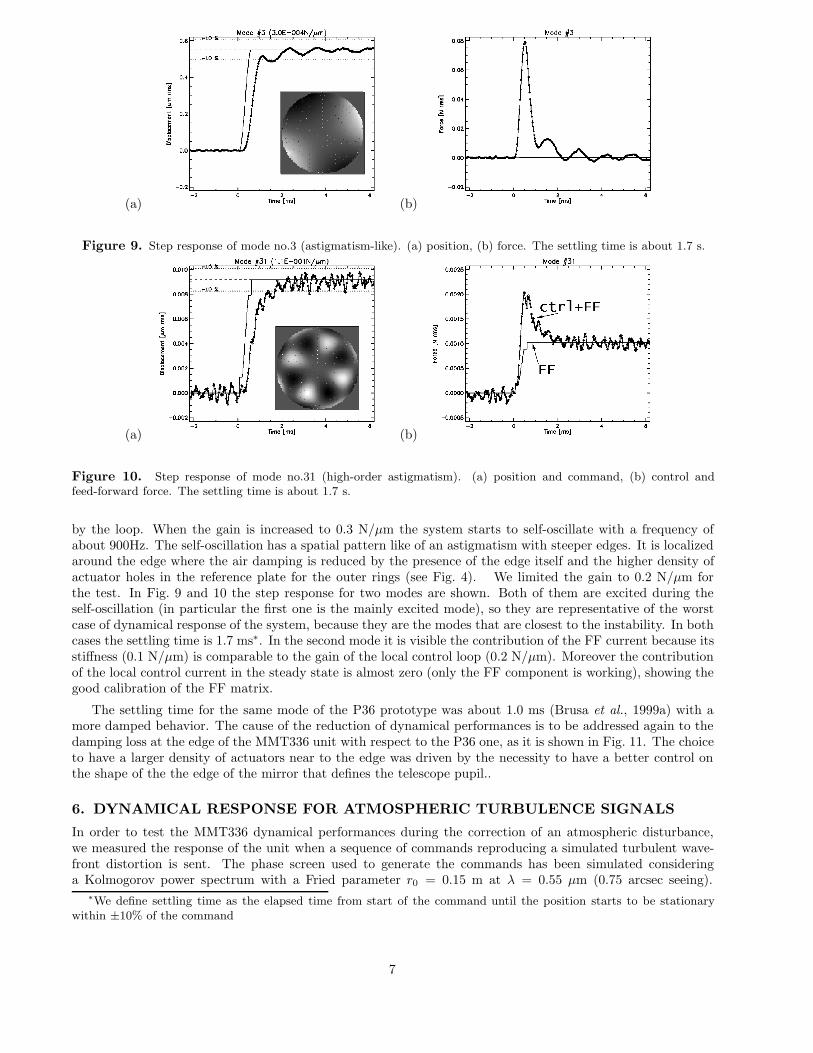
Figure 9. Step response of mode no.3 (astigmatism-like). (a) position, (b) force. The settling time is about 1.7 s.
(a) (b)
Figure 10. Step response of mode no.31 (high-order astigmatism). (a) position and command, (b) control andfeed-forward force. The settling time is about 1.7 s.
by the loop. When the gain is increased to 0.3 N/µm the system starts to self-oscillate with a frequency ofabout 900Hz. The self-oscillation has a spatial pattern like of an astigmatism with steeper edges. It is localizedaround the edge where the air damping is reduced by the presence of the edge itself and the higher density ofactuator holes in the reference plate for the outer rings (see Fig. 4). We limited the gain to 0.2 N/µm forthe test. In Fig. 9 and 10 the step response for two modes are shown. Both of them are excited during theself-oscillation (in particular the first one is the mainly excited mode), so they are representative of the worstcase of dynamical response of the system, because they are the modes that are closest to the instability. In bothcases the settling time is 1.7 ms∗. In the second mode it is visible the contribution of the FF current because itsstiffness (0.1 N/µm) is comparable to the gain of the local control loop (0.2 N/µm). Moreover the contributionof the local control current in the steady state is almost zero (only the FF component is working), showing thegood calibration of the FF matrix.
The settling time for the same mode of the P36 prototype was about 1.0 ms (Brusa et al., 1999a) with amore damped behavior. The cause of the reduction of dynamical performances is to be addressed again to thedamping loss at the edge of the MMT336 unit with respect to the P36 one, as it is shown in Fig. 11. The choiceto have a larger density of actuators near to the edge was driven by the necessity to have a better control onthe shape of the the edge of the mirror that defines the telescope pupil..
6. DYNAMICAL RESPONSE FOR ATMOSPHERIC TURBULENCE SIGNALS
In order to test the MMT336 dynamical performances during the correction of an atmospheric disturbance,we measured the response of the unit when a sequence of commands reproducing a simulated turbulent wave-front distortion is sent. The phase screen used to generate the commands has been simulated consideringa Kolmogorov power spectrum with a Fried parameter r0 = 0.15 m at λ = 0.55 µm (0.75 arcsec seeing).
∗We define settling time as the elapsed time from start of the command until the position starts to be stationarywithin ±10% of the command
7
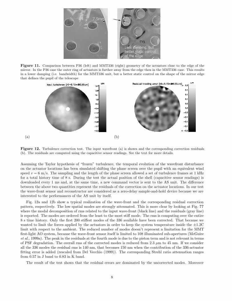
Figure 11. Comparison between P36 (left) and MMT336 (right) geometry of the actuators close to the edge of themirror. In the P36 case the outer ring of actuators is further away from the edge then in the MMT336 case. This resultsin a lower damping (i.e. bandwidth) for the MMT336 unit, but a better static control on the shape of the mirror edgethat defines the pupil of the telescope
(a) (b)
Figure 12. Turbulence correction test. The input wavefront (a) is shown and the corresponding correction residuals(b). The residuals are computed using the capacitive sensor readings. See the text for more details.
Assuming the Taylor hypothesis of “frozen” turbulence, the temporal evolution of the wavefront disturbanceon the actuator locations has been simulated shifting the phase screen over the pupil with an equivalent windspeed v = 6 m/s. The sampling and the length of the phase screen allowed a set of turbulence frames at 1 kHzfor a total history time of 8 s. During the test the actual position of the shell (capacitive sensor readings) isdownloaded every 1 ms and, at the same time, a new command vector is sent to the AS unit. The differencebetween the above two quantities represent the residuals of the correction on the actuator locations. In our testthe wave-front sensor and reconstructor are considered as a zero-delay sample-and-hold device because we areinterested to the performances of the AS unit by itself.
Fig. 12a and 12b show a typical realization of the wave-front and the corresponding residual correctionpattern, respectively. The low spatial modes are strongly attenuated. This is more clear by looking at Fig. ??where the modal decomposition of rms related to the input wave-front (black line) and the residuals (gray line)is reported. The modes are ordered from the least to the most stiff mode. The rms is computing over the entire8 s time history. Only the first 200 stiffest modes of the 336 available have been corrected. That because wewanted to limit the forces applied by the actuators in order to keep the system temperature inside the ±1.2Climit with respect to the ambient. The reduced number of modes doesn’t represent a limitation for the MMTfirst-light AO system, because the wave-front sensor itself is limited to 108 illuminated sub-apertures (McGuireet al., 1999a). The peak in the residuals at the fourth mode is due to the piston term and is not relevant in termsof PSF degradation. The overall rms of the corrected modes is reduced from 2.3 µm to 45 nm. If we considerall the 336 modes the residual rms is 140 nm, that becomes 150 nm when the contribution of the 336-actuatorfitting error is added (rescaled from Del Vecchio (1999)). The corresponding Strehl ratio attenuation rangesfrom 0.57 in J band to 0.83 in K band.
The result of the test shows that the residual errors are dominated by the uncorrected modes. Moreover
8
(a) (b)
Figure 13. (a) Time history comparing the turbulence command and the correction residual at the location of anactuator. (b)Modal rms over the 8 s time history of the turbulence input wavefront and the correction residuals. Thecorrection have been performed using 200 of the available 336 modes.
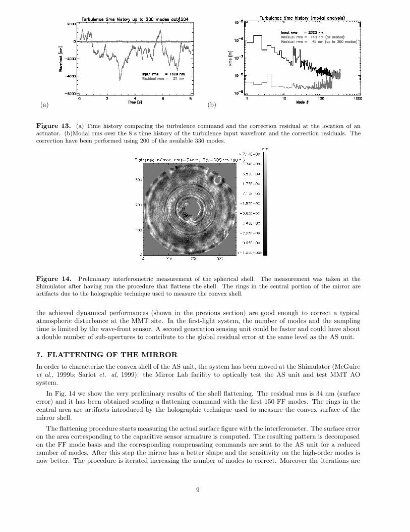
Figure 14. Preliminary interferometric measurement of the spherical shell. The measurement was taken at theShimulator after having run the procedure that flattens the shell. The rings in the central portion of the mirror areartifacts due to the holographic technique used to measure the convex shell.
the achieved dynamical performances (shown in the previous section) are good enough to correct a typicalatmospheric disturbance at the MMT site. In the first-light system, the number of modes and the samplingtime is limited by the wave-front sensor. A second generation sensing unit could be faster and could have abouta double number of sub-apertures to contribute to the global residual error at the same level as the AS unit.
7. FLATTENING OF THE MIRROR
In order to characterize the convex shell of the AS unit, the system has been moved at the Shimulator (McGuireet al., 1999b; Sarlot et. al, 1999): the Mirror Lab facility to optically test the AS unit and test MMT AOsystem.
In Fig. 14 we show the very preliminary results of the shell flattening. The residual rms is 34 nm (surfaceerror) and it has been obtained sending a flattening command with the first 150 FF modes. The rings in thecentral area are artifacts introduced by the holographic technique used to measure the convex surface of themirror shell.
The flattening procedure starts measuring the actual surface figure with the interferometer. The surface erroron the area corresponding to the capacitive sensor armature is computed. The resulting pattern is decomposedon the FF mode basis and the corresponding compensating commands are sent to the AS unit for a reducednumber of modes. After this step the mirror has a better shape and the sensitivity on the high-order modes isnow better. The procedure is iterated increasing the number of modes to correct. Moreover the iterations are
9

necessary to compensate for the miscalibration between the capacitive sensor readings and the interferometermeasurements.
More detailed measurements will be performed on the final aspheric shell that will be tested at the Shimulatorin the near future.
REFERENCESBiasi R., Fini L., Mantegazza P.,Biliotti P., Gori F., and Gallieni D., “Control electronics for an adaptive
secondary mirror,” SPIE Proc. 3353, pp. 1193–1201, 1998.Brusa G., Riccardi A., Ragland S., Esposito S., Del Vecchio C., Fini L., Stefanini P., Biliotti V., Ranfagni P.,
Salinari P., Gallieni D., Biasi R., Mantegazza P., Sciocco G., Noviello G., and Invernizzi S., “Adaptivesecondary P30 prototype: laboratory results,” SPIE Proc. 3353, pp. 764–775, 1998.
Brusa G., Riccardi A., Biliotti V., Del Vecchio C., Salinari P., Stefanini P., Mantegazza P., Biasi R., An-drighettoni M., Franchini C., and Gallieni D., “The adaptive secondary mirror for the 6.5m conversion ofthe multiple mirror telescope: first laboratory testing results,” SPIE Proc. 3762, pp. 38-49, 1999a
Brusa G., Riccardi A., Accardo A., Biliotti V., Carbillet M., Del Vecchio C., Esposito S., Femenıa B.,Feeney O., Fini L., Gennari S., Miglietta L., and Salinari P., “From adaptive secondary mirrors to extra-thin extra-large adaptive primary mirrors,” in Workshop on Extremely Large Telescopes, Torben Ander-son; Arne Ardelberg; Roberto Gilmozzi; Eds., ESO Proc. 57, p. 181–201, 1999b
Del Vecchio C., Gallieni W., Salinari P., and Gray P. M., “Preliminary mechanical design of an adaptivesecondary unit for the MMT-conversion telescope,” in Adaptive Optics, M. Cullum, ed., Proc OSA andESO 54, pp. 243–249, 1995.
Del Vecchio C., “Supporting a magnetically levitated, very thin meniscus for an adaptive secondary mirror:the optimization of the magnetic circuit,” SPIE Proc 3126, pp. 605–613, 1997.
Del Vecchio C., Brusa G., Gallieni D., Lloyd-Hart M., and Davison W. B., ”Static and dynamic responsesof an ultra-thin, adaptive secondary mirror,” SPIE Proc. 3762, pp. 330-340, 1999
Del Vecchio C., and Gallieni D., “Numerical simulations of the LBT adaptive secondary mirror,” SPIE Proc4007, p.516, 2000
Del Vecchio C., Gallieni D., Martin H.M., Riccardi A., Brusa G., and Biasi R., “Design improvements of theLBT adaptive secondary,” in the present conference, 2001
Gallieni D., Del Vecchio C., Anaclerio E., and Lazzarini P. G, “LBT adaptive secondary preliminary design,”SPIE Proc., 4007, p. 508, 2000
Lloyd-Hart M., Wildi F., Martin H., McGuire P., Kenworthy M., Johnson R., Fitz-Patrick B., Angeli G.,Miller S., Angel R., “Adaptive Optics at the 6.5 m MMT,” SPIE Proc. 4007, pp. 167–174, 2000
Martin H., Burge J., Del Vecchio C., Dettmann L., Miller S., Smith B. and Wildi F., “Optical fabrication ofthe MMT adaptive secondary mirror,” SPIE Proc. 4007, p.502, 2000
McGuire P. C., Rhoadarmer T. A., Lloyd-Hart M., Shelton J. C., Lesser M. P., Angel R., Angeli G.,Hughes J.M., Fitz-Patrick B.C., Rademacher M.L., Schaller P., Kenworthy M.A., Wildi F., Capara J.G.,Ouellette D.B., ”Construction and testing of the wavefront sensor camera for the new MMT adaptiveoptics system,” SPIE Proc. 3762, pp. 269–282, 1999a
McGuire P.C., M. Lloyd-Hart, J.R.P. Angel, G.Z. Angeli, R.L. Johnson, B.C. Fitzpatrick, W.B. Davison,R.J. Sarlot, C.J. Bresloff, J.M. Hughes, S.M. Miller, P. Schaller, F.P. Wildi, M.A. Kenworthy, R.M.Cordova, M.L.Rademacher, M.H. Rascon, J.H. Burge, B.L. Stamper, C.Zhao, P. Salinari, C.Del Vecchio,A. Riccardi, G.Brusa, R. Biasi, M. Andrighettoni, D. Gallieni, C. Franchini, D.G. Sandler, T.K. Barrett,”Full-system laboratory testing of the F/15 deformable secondary mirror for the new MMT adaptive opticssystem,” SPIE Proc. 3762, pp. 28–37, 1999b
Riccardi A., Brusa G., Biliotti V., Del Vecchio C., Salinari P., Stefanini P., Mantegazza P., Biasi R., An-drighettoni M., Franchini C., Gallieni D., Lloyd-Hart M., McGuire P. C., Miller S. M., and Martin H.,“The adaptive secondary mirror for the 6.5m conversion of the multiple mirror telescope: latest laboratorytest results of the P36 prototype,” SPIE Proc 4007, p.524, 2000.
Salinari P., Del Vecchio C., and Biliotti V., “A study of an adaptive secondary mirror,” in ICO 16 SatelliteConference on Active and Adaptive Optics, F. Merkle, ed., ESO Proc. 48, pp. 247–253, 1993.
Sarlot R.J., Bresloff C.J., Burge J.H., Fitz-Patrick B.C., McGuire P.C., Stamper B.L., Zhao C.Y., “Progressreport on the optical system for closed-loop testing of the multiple mirror telescope adaptive secondarymirror,” SPIE Proc. 3779, pp. 110-117, 1999
10