the advantages of supercritical circulating fluidized bed boiler (posted by p.muthu, dgm-tsx)
DESCRIPTION
The Advantages of Supercritical Circulating Fluidized Bed BoilerTRANSCRIPT

THE ADVANTAGES OF A SUPERCRITICAL CIRCULATING
FLUIDIZED BED BOILER
Ragnar Lundqvist Foster Wheeler Energia Oy
P.O.Box 45, FIN-00401 Helsinki, Finland
Rudolf Kral Siemens AG, PG W731
P.O.Box 3220 91050 Erlangen, Germany
Pertti Kinnunen
Foster Wheeler Energia Oy P.O.Box 201, FIN-78201 Varkaus, Finland
Kari Myöhänen Foster Wheeler Energia Oy
P.O.Box 66, FIN-48601 Karhula, Finland
ABSTRACT
Modern power plants are designed not only for high efficiency for economical reasons but
also for enhanced environmental performance in terms of reduced fuel needs, quantity of
ash generated, and pollutants emitted. Cutting CO2 has also been a focus of attention. To
achieve these goals, supercritical steam parameters have been applied. Most large
European thermal power plants built for fossil fuels such as coal and brown coal over the
last decade have had supercritical steam parameters and have been based on pulverized
coal fired once-through boiler technology.
Circulating fluidized bed (CFB) boiler technology based on natural circulation has reached
utility scale over the last decade. Plants sizes up to 300 MWe are in operation. A natural
development is to take the technology a step further with larger sizes and supercritical
steam parameters. CFB boilers have features that make them advantageous to use in a
once-through mode. One advantage of the CFB is its insensitiveness to fuel composition
variations and its fuel flexibility. The even combustion characteristic of the thermal wheel
ensures minimum tube temperature unbalance despite variations in fuel properties. Multi-
fuel capability is also an inherent characteristic of a CFB and naturally also in a boiler with
supercritical steam parameters. These are clear advantages for plant owners, as fuel
property variations and availability will not become an issue but give owners a greater
degree of freedom to use the most economical fuel available. Other positive features are
the low gaseous emission capability of CFB boilers without additional flue gas cleaning
equipment and lower water/steam pressure losses due to the Benson Vertical Low Mass
Flux Technology developed by Siemens.
The paper describes these advantageous features in a 460 MWe boiler concept. The
Siemens low mass-flux Benson vertical once-through technology for a CFB boiler is
described in more detail. Special emphasis is laid on furnace behaviour in various
situations, such as uneven firing or load changes. The effect of variations in furnace
temperature on the water/steam circuit and the boiler tube temperature profiles are shown.
The results from simulations and testing are presented.
INTRODUCTION
Debate on future energy management and what types of energy should be used continues
to be quite intensive. Coal remains somewhat unpopular due to the perception that coal-
fired plants pollute the atmosphere. Flue gas cleaning technologies have made major
improvements here. Modern power plants are designed for high efficiency, not only for
economical reasons but also for environmental reasons, such as reducing fuel usage, the
quantity of ash generated, and cutting pollutants emitted. Cutting emissions of CO2 has
also been increasingly highlighted. Supercritical steam parameters have been applied as a
first step to achieving these goals. Most larger European thermal power plants fired on
fossil fuels such as coal and brown coal that have been commissioned over the last decade
have incorporated supercritical steam parameters, based on pulverized coal fired once-
through boiler technology.
Circulating fluidized bed (CFB) technology has emerged as a growing challenger to
conventional pulverized coal-fired boilers in energy generation. Over the last decade,
circulating fluidized bed (CFB) boiler technology based on natural circulation has reached
utility scale. The largest units in operation are two 300 MWe CFB boilers at Jacksonville
Energy Authority (JEA) in Jacksonville, Florida, U.S.A. These boilers burn either 100%
coal or 100% petroleum coke or any combination of the two. The largest unit under
construction is a 340 MWe boiler for ENEL in Sardinia, Italy. This is scheduled to come on
line in 2005 according to /1/.
A natural step in CFB development is to take the technology a step further, to larger sizes
with supercritical steam parameters. This work has called for a continuous and determined
effort on the part of Foster Wheeler. Consideration has had to be given to mechanical
design issues and understanding the process conditions affecting heat transfer, flow
dynamics, carbon burnout, gaseous emission suppression, hydraulic flows etc..
Understanding these process has been helped by the use of bench-scale test rigs, pilot
plants, field testing of operating units, model development, and simulation using developed
semi-empirical models or more theoretical models. Design criteria for larger units have
been developed and successfully implemented on the basis of data collected, model
development work, and correlations with conventional boiler design.
The Foster Wheeler supercritical once-through boiler (OTU) employs a licenced
application of Siemens’ low mass-flux Benson vertical once-through technology. Foster
Wheeler Energia Oy from Finland, Siemens AG from Germany, the Technical Research
Center of Finland, and Energoprojekt Katowice from Poland are participating in a EU-
funded program, High Performance Boiler (HIPE), under the 5th Framework with the goal
of further developing the CFB OTU technology. The Benson system, together with the test
results from this program along with a design description of a 460 MWe unit, are discussed
below.
SIEMENS LOW MASS-FLUX BENSON VERTICAL OTU TECHNOLOGY
With a total of more than 1,000 units delivered over many years to the power generation
industry, the BENSON boiler is the most commonly used type of once-through boiler. It
operates at power levels of up to 1,300 MWe, steam pressures of up to 350 bar, and steam
temperatures of up to well over 600°C. More than a quarter of the units operate at
supercritical pressures. BENSON technology is centered on the evaporator design and has
been licensed by Siemens since 1933. It is a once-through design suitable for sub- and
supercritical pressure and variable pressure operation. Steam generators using the
BENSON design incorporate features, which are critical to economic success in today’s
competitive power markets. These features include:
a highly efficient water/steam cycle as a result of supercritical pressures and high
steam temperatures
insensitivity of steam output and steam temperature to fluctuating fuel properties
the capability for rapid load changes due to variable-pressure operation and short
start-up times, thanks to thermoelastic design.
The extensive worldwide use of the BENSON boiler is in no small measure the result of
ongoing efforts to develop the technology. The expanded knowledge base obtained
through detailed studies, particularly of the heat transfer mechanisms within the furnace
tubes, has made an important contribution to this effort. New evaporator designs will

continue to improve operating behavior and make the manufacturing of the boilers more
cost-effective.
The BENSON Low Mass Flux design is unique. Earlier furnaces were designed with
spiral-wound tubes, and operating experience extending over more than 30 years with
several hundred boilers exists. A new development started in the 1980s in the form of
vertical evaporator tubing with low mass flux based on the use of rifled tubes. Heat transfer
in a rifled tube is very good, especially during evaporation since centrifugal forces
transport the water fraction of the wet steam to the tube wall. The resulting wall wetting
results in excellent heat transfer from the wall to the fluid. This has the following
advantages over smooth tubes:
No deterioration of heat transfer, even in the range of high steam quality
Very good heat transfer, even at low mass flux
Only a slight increase in wall temperature in the case of film boiling near critical
pressure
Potential for increased heat transfer by optimization of rifling geometry
The Siemens high-pressure test rig – the largest in the world with an electrical heater
capacity of about 2,000 kW – was used to generate more than 200,000 data points in an
investigation of standard commercial rifled tubes and tubes with modified rifling
geometry. Changes to the rifling geometry permit significant improvements in heat
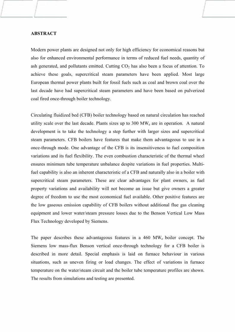
transfer to be achieved as can be seen in Figure 1.
A vertical tube arrangement on the one hand, and rifling on the other, allow a design with
very low mass flux. This low mass flux changes the flow characteristic of a once-through
system. Increased heat input to an individual tube leads to increased throughput for the
tube concerned instead of reduced throughput, as might be expected. This flow behavior –
typical of drum boilers – is known as a natural circulation or positive flow characteristic.
The advantages of a vertically tubed furnace can be summarized as follows:
Mass flux reduction from 2,000 to 1,000 kg/m²s with a similar flow characteristic
to that of drum boilers
Cost-effective fabrication and assembly
Low BENSON minimum load and simple start-up system
Reduced slagging and erosion on furnace wall due to parallel gas flow
Reduced evaporator pressure drop
° C
kJ/kg
SmM osostfhutux b1e0a l 00 k g m/ s 2
StMaansdsaf rdu r1if0le0d 0 t ku be 2l x /g m s
OMpatisms ilfzeudx ri01 fl0e 0d kt gu/ b me 2 s
4 4 0 ° C
4 0 0 3 8 0 3 6 0
e m p e r a t u r ea l tlI n n e r w
Fluid2 4 0 0
e n t h a p y l22002000
4 4 0
4 0 0 3 8 0 3 6 0
1 8 0 0
2200 2 4 0 0 SmM osostfhutux b1e5
kJ/kg
a l 00 k g m/ s 2
StMaansdsaf rdu r1if0le0d 0 t ku be 2l x /g m s OMpatisms ilfzeudx r7i7fl0e kd gtu mb 2e s /
2 x l u 13
12 b 0 ar kW/m2P r eP
ss uk ea
rh
e a t f e
20001 8 0 0
Figure 1 Rifled tubes reduce wall temperatures or allow mass flux reduction
The BENSON low mass flux design was first tested in the Farge 420 MWe supercritical
power plant with a few smaller testing sections. The first coal-fired boiler with an
evaporator based on the Siemens low mass flux design was built in Yaomeng, China and
has now been in successful operation since mid-2002. The boiler – a repowering project of
a 300 MW power plant – incorporates the special challenge of a center water wall with
heat input from both sides configured parallel to the water walls. Despite the large
variations in heat input between the outer water walls and the center water wall, the
temperature variations at the outlet of the water wall heat exchange surfaces are negligible.
Table 1 shows the references CFB Benson boilers and PC’s with low mass flux
installations.
CFB plants incorporating once-through boilers with ratings of up to 100 MWe have been in
operation for many years. The state of the art when these plants were constructed featured
a relatively elaborate riser–downcomer system for the water walls. The largest CFB plants
to date with ratings of about 300 MWe are designed with drum boilers. However, once-
through operation and elevated steam conditions up to approximately 600°C and 300 bar
are required to make CFB technology a real competitor to pulverized coal firing for large
plants. As part of the EU HIPE research program, an evaporator concept for a 500 MWe
CFB plant was elaborated based on the Siemens low mass flux design, and fluid mechanics
analysis performed. This also included heat transfer measurements in the BENSON test rig
on a rifled tube, such as that used in the intermediate water walls of the combustor subject
to heat input from both sides.
Power Plant Type Flow (kg/s)
Temp.(°C)
Pressure (bar)
Contrac-tual Date
Manufacturer
SW Duisburg CFB 75 535 140 1983 Babcock Borsig
Bayer Leverkusen 1 CFB 2 x 39 580 140 1984 Burmeister+Wain
Bayer Leverkusen 2 CFB 2 x 39 580 140 1988 Burmeister+Wain
Berlin Moabit CFB 91 540 190 1986 Burmeister+Wain
KW Farge Test Loop PC 300 535 250 1996 Babcock Borsig
Yaomeng (China) PC 278 545 164 2001 Mitsui Babcock
Table 1 BENSON references for CFB and PC boilers with vertical tubing (SW Duisburg
has no vertical tubing but horizontal) Due to differing geometries and differing heat inputs involved, the evaporator had to be
subdivided into a number of systems, configured in parallel. The individual mass flows and
the corresponding outlet temperatures from the water wall sections were then determined
for this configuration. The effects of variations in heat input and the loss of a fuel feeder on
the temperatures were also investigated.
The selection of a relatively low design mass flux – between 400 kg/m²s and 700 kg/m²s
depending on the type of tube – yields a good positive flow characteristic for all tubes.
This has the result that even large variations in heat input are essentially evened out by the
adjustment of the individual mass flows, which takes place automatically as a result of the
self-regulating characteristic. At full load, the differences between the highest and lowest
individual tube temperatures at the evaporator outlet are only 35 K, even on loss of a fuel
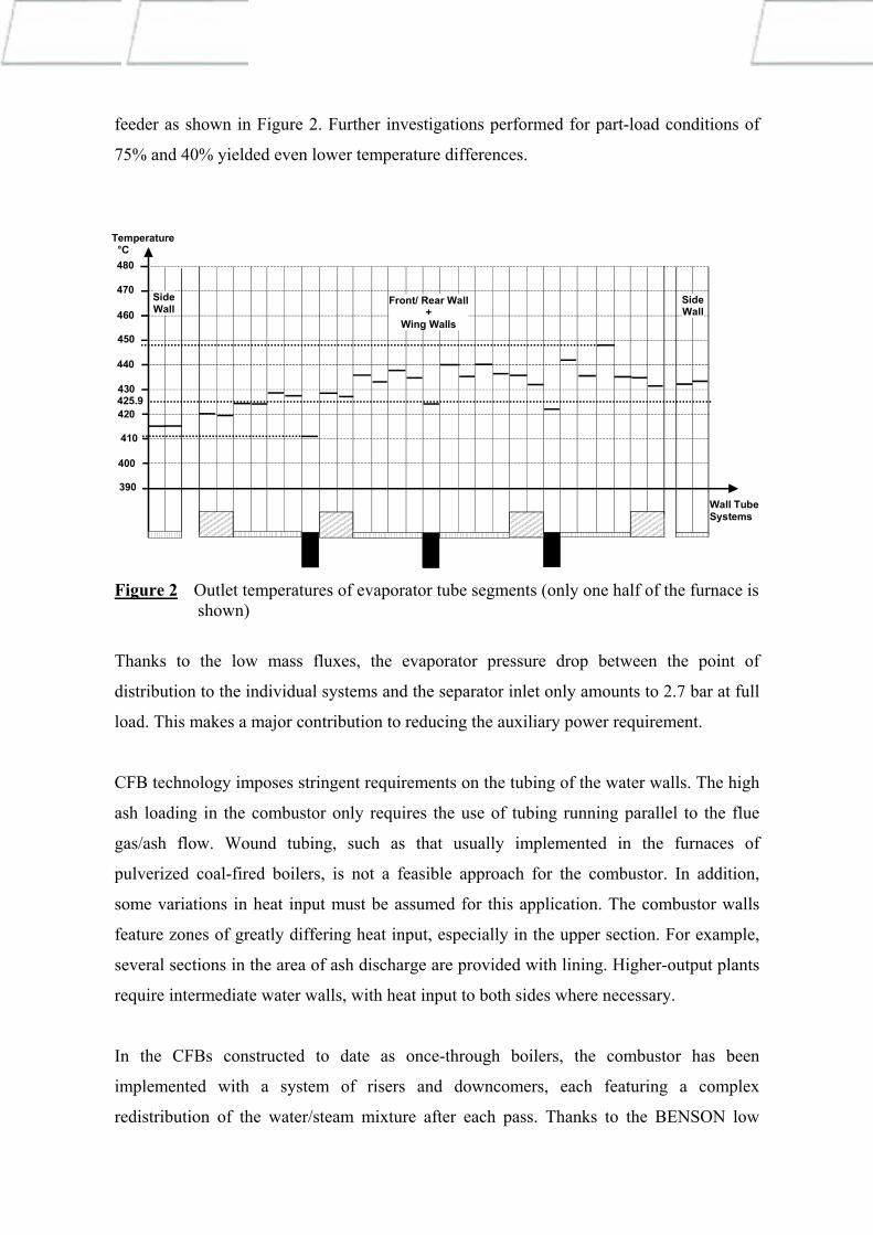
feeder as shown in Figure 2. Further investigations performed for part-load conditions of
75% and 40% yielded even lower temperature differences.
48
46
45
44
4342
41
40
39
0
0
0
420
0
0
0
0
470
Temperature °C
Front/ Rear Wall+
Wing Walls
SideWall
SideWall
Wall TubeSystems
5.9
0
Figure 2 Outlet temperatures of evaporator tube segments (only one half of the furnace is shown)
Thanks to the low mass fluxes, the evaporator pressure drop between the point of
distribution to the individual systems and the separator inlet only amounts to 2.7 bar at full
load. This makes a major contribution to reducing the auxiliary power requirement.
CFB technology imposes stringent requirements on the tubing of the water walls. The high
ash loading in the combustor only requires the use of tubing running parallel to the flue
gas/ash flow. Wound tubing, such as that usually implemented in the furnaces of
pulverized coal-fired boilers, is not a feasible approach for the combustor. In addition,
some variations in heat input must be assumed for this application. The combustor walls
feature zones of greatly differing heat input, especially in the upper section. For example,
several sections in the area of ash discharge are provided with lining. Higher-output plants
require intermediate water walls, with heat input to both sides where necessary.
In the CFBs constructed to date as once-through boilers, the combustor has been
implemented with a system of risers and downcomers, each featuring a complex
redistribution of the water/steam mixture after each pass. Thanks to the BENSON low
mass flux design, an evaporator concept is now available that fulfills the above
requirements and is cost-effective, thanks to its inherent simplicity. Medium flows take
place in parallel through all tubes in one pass and no distribution of water/steam mixture is
required. There are only negligible variations in temperature between the tubes at the outlet
from the combustor, as variations in heat input are evened out by the positive flow
characteristic. The relatively low heat flux in the combustor compared to that in the
furnace of pulverized coal-fired boilers allows smooth tubes to be used for the water walls
with single-sided heat input. In addition, the unlimited suitability of the evaporator system
for variable pressure operation also fulfills all of the requirements for a power plant with
regard to operating flexibility.
COMBUSTION SIDE STUDIES WITH THE LOW MASS-FLUX OTU CFB
The CFB process also has a number of merits when applying supercritical OTU
technology. In particular, the nature of CFB combustion results in low and uniform heat
flux, due to relatively low combustion temperature and uniformity of temperature resulting
from the circulating solids in the furnace. Although it can seem self evident that circulating
solids provide a thermal wheel, smoothening out any temperature spikes, it has to be
proven under all types of conditions to ensure that overheating of the furnace tubes cannot
take place.
This has required a lot of R&D to understand the combustion process behavior in the
furnace. The release of heat in the combustion process, heat transfer, and gas and flow
dynamics have to be well understood. Work has concentrated on testing and measuring
these issues in bench-scale test rigs, pilot plants, and operational units, and developing
empirical and semi-empirical models and using these in combination with more theoretical
models to create simulation tools.
Boiler combustion behavior and its influence on heat flux and heat transfer can now be
modelled accurately in a 3-dimensional model and validated. The model combines
fundamental balance and momentum equations and empirical correlations. Theoretical
equations are used for those phenomena for which the governing equations are defined and
acceptable. Empirical correlations are used for phenomena for which the theoretical
equations are not known or the theory is too complex, resulting in unacceptable computing
times.
The most important phase in the development of the models and correlations has been the
validation using measurements in real conditions. For validating a three-dimensional
model, the standard measurements for defining overall mass and energy balance are
required, but are in themselves insufficient. Profile measurements have been carried out in
various parts of the furnace, and measurement locations extended well inside the furnace.
It is also essential to know more about fuel and limestone behaviour in areas such as
attrition. An extensive program has been conducted to measure heat transfer and heat
fluxes, combustion profiles, and other issues in large-scale units. One part of the total
program has been the measurements carried out under an EU-supported project “In
Furnace Process in a 235 MWe CFB Boiler” in one of the units at Turów Power Station in
Bogatynia, Poland. The partners in the project have been the plant, Technical University
Hamburg-Harburg, Częstochowa Technical University, the Technical University of
Ostrava, Chalmers University of Technology, and Foster Wheeler Energia Oy. A more
detailed description of the development of the models is presented in /2/.
The temperature and the heat flux are relatively uniform in the furnace. Of interest for
boiler operation are situations when a fuel feeder trips and the rest of the feeders have to
pick up the feed rate. If a boiler is sensitive to such disturbances, some partial overheating
or imbalance could occur. This has been studied extensively for a CFB boiler in a size
range of 400-500 MWe. In the case of a corner feeder tripping as described in Table 2 , not
very much happens to the heat flux or the combustion temperature. Figure 3 shows the
heat flux and the differences, and Figure 4 shows the temperature distribution and the
difference. For illustrative purposes, the colors show a large difference, but in fact the
numerical changes are very small.
Case 1: – Basic case.
– Uniform fuel feeding to all the feeding points. Case 2: – Fuel feed stopped to feeding point at front-right corner.
– Feed rate to other feeders increased equally. Table 2 The cases studied in heat flux distribution
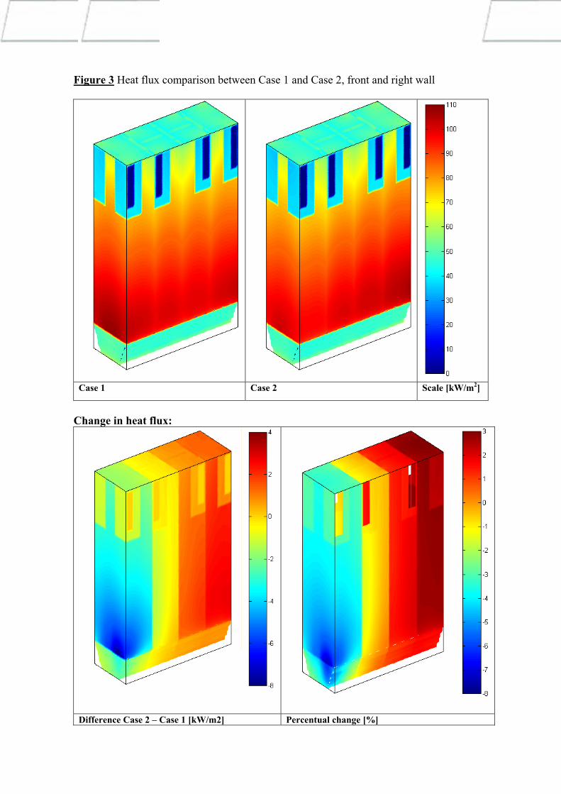
Figure 3 Heat flux comparison between Case 1 and Case 2, front and right wall
Case 1 Case 2 Scale [kW/m2]
Change in heat flux:
Difference Case 2 – Case 1 [kW/m2] Percentual change [%]

Figure 4 Gas temperature comparison between Case 1 and Case 2
Case 1 Case 2 Scale [°C] Difference in gas temperature [°C] (Case 2 – Case 1):
Case 1 – Case 2 Scale [ºC]

The difference in gas temperature at its maximum is close to 25 ºC, but it does not have a
very big influence on heat flux. Figure 5 presents the percentage change at different
horizontal locations on the furnace walls at an elevation of approximately 6 meters from
the grid. The heat flux changes gradually from front to back of the furnace. Such
percentage changes have no significant impact on wall metal temperatures. The change is
in the order of a few degrees.
Figure 5 Percentage change in heat flux in horizontal direction when one fuel feeder trips.
Using a reliable tool such as this, sensitivity analyses can be carried for a number of
situations. Such studies are valuable for different operational modes.
ADVANTAGES OF A SUPERCRITICAL OTU CFB BOILER
Siemens low mass-flux Benson OTU technology results in a lower water/steam side
pressure drop, which reduces feed water pump power consumption and thereby reduces the
plant net heat rate.
Other advantages of an OTU CFB include the fact that a low heat flux makes boiler tubes
insensitive to overheating. In addition, the following advantages should be mentioned:
fuel flexibility
multi-fuel capability
low emissions without the need for secondary clean-up
One inherent feature of a CFB boiler is its insensitiveness to fuel composition variations.
In many cases, coal or brown coal from the same mine varies widely in terms of heat
value, ash content, and moisture. Such variations do not materially affect the combustion
temperature due to the thermal wheel that the circulating solids create. An even
combustion temperature also means even heat flux, which means even temperatures in the
boiler tubes.
Multi-fuel operation is another inherent feature of a CFB, operating with supercritical
steam parameters. When feeding several different fuels heat fluxes will also be low and
even, due to the bed material and the circulating solids. These are clear advantages for a
plant owner, as fuel property variations and fuel availability will not become an issue, but
will give owners a larger degree of freedom to use the most economical fuel source.
Another advantage of the CFB is its low gaseous emission capability without the use of
additional flue gas cleaning equipment. In large-scale power plants, the cost of flue gas
desulphurization (FGD) and selective catalytic reduction (SCR) can be very significant.
Furthermore, a SCR system requires ammonia injection and the catalyst must be replaced
on a regular basis. A CFB produces more ash, since in-furnace sulfur reduction is not as
efficient as an FGD. On the other hand, limestone can be used directly and lime is not
required. The end-product is always dry and there are no wet discharge streams.
In terms of absolute efficiency, a CFB cannot achieve the same combustion efficiency as a
pulverized coal-fired unit. However, due to the characteristics of the boilers, a lower flue
gas exit temperature can be achieved, which compensates for the slightly less efficient
combustion. The reason for the lower flue gas temperature is the economizer, which can be
used more effectively in a CFB. The water temperature can be raised in the economizer
while still maintaining the right steam/water ratio by weight in the furnace tubes, as the
heat fluxes are lower than in a pulverized coal-fired unit. While more auxiliary power is
needed for fluidization, no mills are required and there is no additional flue gas pressure

drop due to FGD and SCR units, and no water consumption as in a FGD. The power
demand of these components are more or less equal to the power needed for fluidization.
Overall, a CFB boiler offers many advantages, which should act as driving forces to utilize
this technology in future large-scale power production based on coal or brown coal.
THE 460 MWe ONCE THROUGH CFB ŁAGISZA PROJECT
In October 2001, the Polish utility Południowy Koncern Energetyczny S.A, (PKE)
solicited quotations for a 460 MWe once through supercritical, coal-fired boiler plant. PKE
is located in southern Poland in Katowice and is the largest utility in Poland, operating
eight power plants within a 50 km radius from Katowice. The company has installed
capacity of over 4795 MWe, which is approximately 17 %of Poland’s total generating
capacity. In addition, the company has over 2,000 MWth of district heating capacity, which
accounts for 16% of the local heat generating requirements of the Katowice area.
The two-phase bidding process was defined with two alternative combustion technologies:
pulverized combustion and circulating fluidized bed combustion. During the first phase,
the proposals were submitted based on the preliminary turbine conditions at the end of
February 2002. During the second phase, the turbine conditions were more precise and the
proposal submittal took place at the end of October 2002.
Foster Wheeler submitted proposals for both combustion alternatives. Both boiler
proposals were based on Benson technology with vertical tubing and low mass flux. Foster
Wheeler was selected as the boiler supplier on December 30, 2002, with both combustions
technologies. A detailed evaluation of both alternatives started in January 2003, together
with an analysis of the associated investment and operational costs.
The scope of Foster Wheeler’s offer includes the boiler island supply based on an EPC
delivery basis: engineering and design, civil works and foundations, boiler house enclosure
with steel structures, boiler pressure vessels with auxiliary equipment, main steam piping
to turbine and re-heated steam piping, coal bunkers and fuel feeding equipment,
electrostatic precipitator and cold end flue gas heat recovery system, erection, construction,
start up, and commissioning. A coal slurry system was included in the contract as a
possible later option. The time schedule of the project is as follows:
- Contract signing December 30, 2002
- Start Basic Engineering March 1, 2003
- Effective date of the contract October 1, 2003
- Mechanical completion February 28, 2006
- Commercial operation September 30, 2006
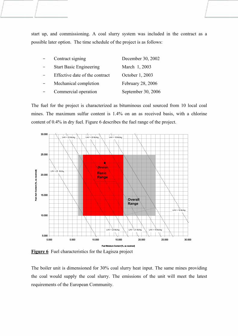
The fuel for the project is characterized as bituminous coal sourced from 10 local coal
mines. The maximum sulfur content is 1.4% on an as received basis, with a chlorine
content of 0.4% in dry fuel. Figure 6 describes the fuel range of the project.
Design
5.000
10.000
15.000
20.000
25.000
30.000
0.000 5.000 10.000 15.000 20.000 25.000 30.000
Fuel Moisture Content [%, as received]
Fuel
Ash
Con
tent
[%, a
s re
ceiv
ed]
LHV = 18 MJ/kg
LHV = 25 MJ/kg
LHV = 21 MJ/kg
LHV = 20 MJ/kg
LHV = 19 MJ/kg
LHV = 16 MJ/kg
LHV = 22 MJ/kg
LHV = 23 MJ/kg
Basic Range
Overall Range
Figure 6 Fuel characteristics for the Łagisza project
The boiler unit is dimensioned for 30% coal slurry heat input. The same mines providing
the coal would supply the coal slurry. The emissions of the unit will meet the latest
requirements of the European Community.
ŁAGISZA PROJECT BOILER DATA AND DESIGN
The CFB boiler was dimensioned according to the data in Table 3 below:
Maximum continuous steam flow kg/s 359.8 Minimum continuous steam flow kg/s 143.9 HP steam pressure at turbine inlet MPa 27.50 HP steam temperature at turbine inlet °C 560 Cold reheated steam flow kg/s 306.9 Cold reheated steam pressure MPa 5.46 Cold reheated steam temperature °C 314.3 RH steam temperature at IP turbine inlet °C 580 Feed water temperature °C 289.7
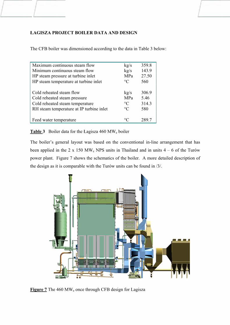
Table 3 Boiler data for the Łagisza 460 MWe boiler The boiler’s general layout was based on the conventional in-line arrangement that has
been applied in the 2 x 150 MWe NPS units in Thailand and in units 4 – 6 of the Turów
power plant. Figure 7 shows the schematics of the boiler. A more detailed description of
the design as it is comparable with the Turów units can be found in /3/.
Figure 7 The 460 MWe once through CFB design for Lagisza

During the preliminary evaluations, the CFB design was found more economical in the
following areas:
Total plant investment cost is lower. The installation of wet scrubbing and SCR
systems that are essential for a PC-based solution can be eliminated.
Plant performance is better. Net plant efficiency using CFB technology and an
advanced flue gas cooling system is approximately 0.3% better that a PC solution.
Fuel flexibility provides a useful safety margin for the future. The unique multi-fuel
capability of the CFB provides a wider fuel range and the additional possibility of
using opportunity fuels. Wet coal slurry waste combustion is included for 30%
capacity in the basic design. Additional fuels such as up to 50% granulated coal
slurry and up to 10% biofuels can be easily adopted during the project or later.
The selection of the technology was made on Fabruary 28, 2003 and a CFB was selcted.
The engineering work for the boiler has begun.
CONCLUSIONS
CFB technology has been considered a technology for niche applications. Today,
however, the technology is challenging the conventional technology, with enhancements in
terms of both scale and efficiency. CFB technology offers a number of advantages for
modern power plants, such as fuel flexibility, multi-fuel capability, and emission control
without the use of secondary systems. Benson Low Mass Flux technology is very suitable
for combination with CFB technology, as it reduces the pressure drop on the steam/water
side, and heat flux is low and even , preventing the type of tube overheating that was
experienced in the past in conventional plants. The proposal and contract for the Łagisza
460 MWe power project strongly indicates that CFB is about to enter a major new stage in
its development.

REFERENCES
/1/ C. Hargehel, S Gabiccini, O Dinale, M. Duprey, R. Hickey, “The Clean Use of High
Sulphur Coal: An Advanced CFB Solution”, presented at PowerGen 2002, June 11-
13, 2002, Milan, Italy
/2/ Kari Myöhänen, Timo Hyppänen, Jouni Miettinen, Riku Parkkonen, ”Three-
Dimensional Modeling and Model Validation of Circulating Fluidized Bed
Combustion”, to be presented at the 17th International Conference on Fluidized Bed
Combustion, May 18-21, 2003, Jacksonville, Florida, U.S.A.
/3/ Roman Walkowiak, Elektrownia Turów S.A., Andrzej Wójcik, Foster Wheeler
Energy International, Inc., Foster Wheeler Energia Polska Sp. z o.o. “Third Phase of
Turów Rehabilitation Project” presented at PowerGen 2001, 8-10 June, 2001,
Helsinki, Finland