the agnitude of m errors associated in measuring the loads
TRANSCRIPT
Journal of Medical Signals & Sensors
Vol 2 | Issue 4 | Oct-Dec 2012 225
inTroducTion
Measuring the loads exerted on the assistive device is a fundamental part of design.[1-7] Measuring is possible using strain gauge system or appropriate transducer.[8,9] A strain gauge is an electronic device, which converts the mechanical energy into electrical signal.[9] The construction of strain gauge and transducer for anatomical force measurement was first described in 1952 by Cunningham and Brown.[10] These authors described both a transducer for incorporation in a prosthesis limb and a device known as force plate or force platform.
Strain gauge technology has been widely used to measure the absolute value of the loads exerted on the assistive devices. However, there are some sources of errors, which influence the final results. The two main sources of error associated with the use of strain gauge include: Absolute error, which influence the overall accuracy and random error, which affects its replication.[8-10] Random errors are easier to detect as they manifest themselves in the inability of the system to give repeatable data. They are usually tested by repeating the test under the same conditions. Controversy
A b s t r A c t
Measurement of the loads exerted on the limb is a fundamental part of designing of an assistive device, which has been done by using strain gauges or a transducer. Although calculation of loads applied on an orthosis coefficients achieved from calibration is a standard way, most of researchers determined the loads based on available equations. Therefore, the aim of this research is finding the accuracy of this method with respect to calibration. Some strain gauges were attached on the lateral bar of a reciprocal gait orthosis. It was calibrated for axial force and the anteroposterior and mediolateral moments. The outputs of strain gauge were changed to force, and moments based on the coefficients were achieved from calibration using available equations, while 5 normal subjects were walking with the orthosis. There was a significant difference between the force and moments exerted on the orthosis during walking based on the two methods (mostly extension moment and compression force). The results of this research indicated that the output of strain gauge varies based on the methods of calculation. As calibration the gauge is a standard method, it is recommended to calibrate it before use.
Key words: Calibration, compression force, moments, orthosis, strain gauge, tension force
The magnitude of errors associated in measuring the loads applied on an assistive device While Walkingmohammad Taghi Karimi, nima Jamshidi1
Rehabilitation Engineering Research Center, Isfahan University of Medical Sciences, 1Department of Biomedical Engineering, University of Isfahan, HezarJerib St., Isfahan, Iran
Submission: 14‑03‑2012 Accepted: 09‑09‑2012
in the reading represents the low level of replication. However, for the accuracy, the strain gauge configuration need to be calibrated against a known load.[9]
Although strain gage have been used in many research studies, a few researchers have calibrated it before using in their main research studies.[10-16] There are two main approaches to convert the output of strain gauge into the mechanical loads, which include using available equations in this regard and calibrate the strain gauge.[9] It is not clear for us that how much is the accuracy of the first method in contrast to calibration, which is a standard method. Therefore, the aim of this research is to find the accuracy of the first method in contrast to calibration method. Moreover, our aim was to find the magnitude of error associated with this method regarding the output of strain gauge attached on the orthosis while walking.
maTerials and meThods
In order to measure the loads exerted on the orthosis while walking, some strain gauge were attached on the lateral bar of a Reciprocal Gait Orthosis. A foil strain gauge,
address for correspondence: Dr. Nima Jamshidi, Department of Biomedical Engineering, Faculty of Engineering (1st floor), University of Isfahan, HezarJerib St., Isfahan, Iran,
Postal Code: 81746 - 73441 E-mail: [email protected]
Original Article
Karimi and Jamshidi.: Loads measurement errors
Journal of Medical Signals & Sensors
Vol 2 | Issue 4 | Oct-Dec 2012226
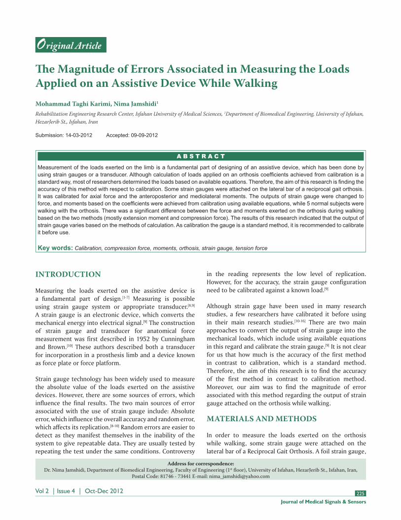
purchased from Showa Measuring Instrument Company,[17] was attached on the lateral bar of the orthosis using special glue recommended by manufacturer, Figure 1. Reference lines were drawn on the lateral bar using of a hard pen. Three bridge strain gauges were connected by special 4 wire ribbon cable to a 25 way terminal plug. The output of amplifier was connected to a DAQ card inserted in a laptop.
procedure undertook for calibration
Static calibration involves the application of loads along the axis of a strain gauge or transducer and recording the output was used.[1,3,9] The weights were made to high degree of accuracy, which exceeds the value required for calibration. The outputs give information on calibration coefficients, which were used to convert the output into the force and moments.
calibration for the bending moments
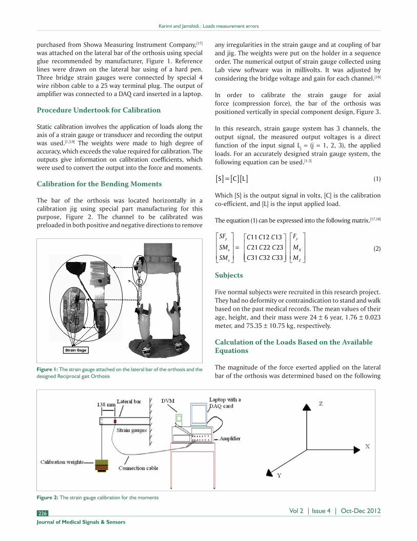
The bar of the orthosis was located horizontally in a calibration jig using special part manufacturing for this purpose, Figure 2. The channel to be calibrated was preloaded in both positive and negative directions to remove
Figure 2: The strain gauge calibration for the moments
Figure 1: The strain gauge attached on the lateral bar of the orthosis and the designed Reciprocal gait Orthosis
any irregularities in the strain gauge and at coupling of bar and jig. The weights were put on the holder in a sequence order. The numerical output of strain gauge collected using Lab view software was in millivolts. It was adjusted by considering the bridge voltage and gain for each channel.[18]
In order to calibrate the strain gauge for axial force (compression force), the bar of the orthosis was positioned vertically in special component design, Figure 3.
In this research, strain gauge system has 3 channels, the output signal, the measured output voltages is a direct function of the input signal Lj = (j = 1, 2, 3), the applied loads. For an accurately designed strain gauge system, the following equation can be used.[1-3]
S = C L[ ] [ ][ ] (1)
Which [S] is the output signal in volts, [C] is the calibration co-efficient, and [L] is the input applied load.
The equation (1) can be expressed into the following matrix.[17,18]
SF
SM
SM
C C C
C C C
C C C
y
x
z
=
11 12 13
21 22 23
31 32 33
F
M
M
y
X
Z
(2)
subjects
Five normal subjects were recruited in this research project. They had no deformity or contraindication to stand and walk based on the past medical records. The mean values of their age, height, and their mass were 24 ± 6 year, 1.76 ± 0.023 meter, and 75.35 ± 10.75 kg, respectively.
calculation of the loads based on the available equations
The magnitude of the force exerted applied on the lateral bar of the orthosis was determined based on the following

Karimi and Jamshidi.: Loads measurement errors
Journal of Medical Signals & Sensors
Vol 2 | Issue 4 | Oct-Dec 2012 227
equations:[9,17,18] The equation 3 and 4 represents stress.
σ = Eε (3)
=F
Ayo (4)
By equaling the equation 3 and 4, the 5 equation has been derived.
=F
AEyo (5)
Also, the relation between input and output voltage and strain has been shown in equation 6 (9).
=2
1 3
*
. * *
V
K Vout
in
(6)
By equaling the equation 5 and 6, the 7 equation has been derived.
FA E V
K Vyo
out
in
=2
1 3
* * *
. * * (7)
Where , , K, A, E, Fyo, Vout, Vin are stress, strain, gauge factor, area, young modulus, the axial force applied on orthosis, output voltage, and input voltage, respectively. The magnitude of Vin for the axial force, A, E, and K were 6 volt, 496 × 10–6 m2, 70 × 109, (Pascal), and 2.02, respectively. By using the values of A, E, and K, the final following equation was achieved.
F Vyo out= 440 7. * (8)
Where, Vout is in millivolt.
The anteroposterior bending moment was calculated based on the following equations (9).
=c zIzz
* M (9)
=V
K Vout
in* (10)
MI E V
c K Vzzz
in
out=
* *
* * (11)
The magnitude of Vin for the bending moments was 3 volts; therefore, the final equation was as followed, where, Vout is in millivolt.
M Voutz = 14 8. * (12)
For the medio-lateral moment, the following equation has been used.[9]
MI E V
c K Vxxx
in
out=
* *
* * (13)
The magnitude of vin for the bending moments was 3 volts; therefore, the final equation was as follow, where, vout is in millivolt.
M Vx out= 7 635. * (14)
The calibration factor for each channel was obtained in units of mV/N for axial force and mV/Nm for the bending moments by performing linear regression, Figure 4. The behavior of strain gage can be determined based on the following equation:
V AppliedMomentout = +0 002611 0 0328. . * ( ) (15)
The equation 14 shows a direct and linear correlation between the magnitude of applied moment, and output voltage has been established. A regression line was fitted to
Figure 3: The calibration of strain gauge for the axial force

Karimi and Jamshidi.: Loads measurement errors
Journal of Medical Signals & Sensors
Vol 2 | Issue 4 | Oct-Dec 2012228
principal calibration co-efficient to check for linearity and also hysteresis.
The voltage output was platted against the input load to check for linearity. The crosstalk of strain gauge, regarding the anteroposterior moment, can be seen in Figure 4. The following equations have been used to convert the output of strain gauge into force and moments (based on calibration results).[19,20]
In the equation 16, 17, and 18, the SFy, SMx, and SMz
represents the output voltage, respectively, from channel Fy,
Mx, and Mz. The coefficients in the following equations were obtained by comparing the applied loads and the outputs of the strain gauge channels.
FySF SM SMy x z= − −
0 00214 0 044113 0 015. . . (16)
MxSM SMx z= −
0 0302 0 5. . (17)
MzSM SMz x= +
0 01643 0 3183. .
(18)
The able-bodied subjects received 2 training session including donning and doffing the orthosis, standing, and walking (each session for 1 hour). For tracing the movement of the subjects, an array of 7 high-speed camera was used produced by Qualysis company. Moreover, the force applied on the leg was measured by a Kistler force plate. Sixteen markers (with 14 mm diameter) were attached to the right and left anterior superior iliac spines (ASIS), right and left posterior superior iliac spines (PSIS), right and left medial and lateral malleolus, right and left medial and lateral sides of the knee joints, and first and fifth metatarsal heads. Knee markers were attached on the skin of the medial and lateral sides of the knee joint while the subjects wore the orthosis. Moreover, 4 marker clusters comprising of 4 markers attached on the rhomboid plates were attached to the anterolateral surfaces of the legs and thighs by use of extensible Velcro straps. The subjects were asked to walk along a level surface to collect 5 successful trials. The collected data were filtered (Woltring filter with frequency of 10 Hz) and split to gait cycle interval using heel strike data.
resulTs
The force and moments exerted on the orthosis while walking were calculated based on the 2 mentioned procedures (the force and moments were normalized by body weight and body mass, respectively). As it is observed in Table 1, the magnitude of the loads exerted on the orthosis differed between the 2 methods. The mean values of flexion moment obtained from using equations and by calibration were
Figure 5: The pattern of the axial force exerted on the orthosis based on the 2 methods, HS – Heel strike
Table 1: The mean values of the applied loads on the orthosis while walking based on the 2 methods
P valueCalibrationEquationMethod
0.150.0366±0.030.052±0.032 Flexion moment (Nm/kg)0.0180.178±0.0060.202±0.0714Extension moment (Nm/kg)0.320.5±0.0950.516±0.051Adduction moment (Nm/kg)
0.0340.286±0.07570.216±0.068Compression force (N/BW)0.120.124±0.08080.096±0.048Tension force (N/BW)
0.052 ± 0.032 and 0.0366 ± 0.03, respectively, (P = 0.15). The magnitude of extension moment differed significantly between the 2 methods (P = 0.018). The magnitude of compression force obtained from calibration was significantly more than that of using equations. Figures 5-7 show the pattern of the loads exerted on the orthosis, while walking, and calculated by 2 methods.
In the first method, the loads were determined based on the commonly used equations mentioned above. In contrast, in the second method, the calculation was based on the coefficients obtained from calibration procedure.
discussion
Calibration is a procedure, in which an acceptable
Figure 4: Calibration of the strain gauge for Mz as the main channel and showing the crosstalk in Mx and Fy

Karimi and Jamshidi.: Loads measurement errors
Journal of Medical Signals & Sensors
Vol 2 | Issue 4 | Oct-Dec 2012 229
standard is compared against an unknown quality; it is used to determine the accuracy of a method or tool. Although there are 2 ways to undertake the calibration, the static calibration is recognized as a standard and more accurate in methods.[9] The accuracy of this method depends on accuracy of the procedure and weights. Bridge non-linearity and uncertain ability of gauge factor are the 2 most important sources of error of strain gauge. The gauge factor has been determined based on information presented by the supplier.
The linearity of strain gauge configuration can be determined based on the results of calibration. As shown in Figure 4, the voltage output was plotted against the input load; the system has a high degree of linearity.
Most of the researchers who used strain gauge measure, the loads applied on the orthosis have not calibrated it before data collection.[11,14,15] However, the results of this research showed that determination the loads based on equation has some source of errors. Most of the researchers do not consider the cross talk (application of the load in one channel produces output in other channels). Based on the results of this research, there was a significant difference between the output of strain gauge determined using of equation and calibration for the extension moment and the compression force. The main reason is that the applied loads in one channel produce output in other channels as
well. Therefore, it is concluded that the strain gauge system, used to determine the loads applied on an orthosis, must be calibrated before use.
The output of strain gauge method is used mostly to design various assistive devices for handicapped subjects. If the loads used in this regard have some errors, the designed assistive devices cannot fulfill their predicted roles and may have failure during walking. Therefore, it is strongly recommended to use the loads obtained based on calibration procedure. The magnitude of errors, associated with obtaining the loads based on equations, depends on the accurate locations of attached strain gauges and could be decreased. However, it is not possible to remove the errors. It is the main reason that force plate needs to be calibrated annually by use of standard weights to remove the cross talk.
conclusion
Calibration of strain gauge has not been done in most of the research studies regarding the loads exerted on the assistive devices. However, it has been determined using equation. The results of this research indicated that the error of equation-based method is high, especially for the extension moment and compression force. Therefore, it is recommended to calibrate strain gauge according to the procedure mentioned in this research.
references
1. Trappitt AE, Berme N. A trasducer for the measurement of lower limb orthotic loads. Eng Med 1981;10:149-53.
2. Maqsood T. Load analysis of a Knee Ankle Foot orthosis, of the cosmetic type. PhD thesis, Glasgow: University of Strathclyde; 1996.
3. Gozal D. Loads analysis of the knee joints of the cosmetic type Knee Ankle Foot orthosis. PhD thesis; Glasgow: University of Strathclyde; 1986.
4. Johnson GR, Ferrarin M, Harrington M, Hermens H, Jonkers I, Mak P, et al. Performance specification for lower limb orthotic devices. Clin Biomech 2004;19:711-8.
5. Stallard J, Woollam PJ, Miller K, Farmer IR, Jones N, Poiner R. An infant reciprocal walking orthosis: Engineering development. Proc Inst Mech Eng H 2001;215:599-604.
6. Woolam PJ, Lomas B, Stallard J. A reciprocal walking orthosis hip joint for young paediatric patients with a variety of pathological conditions. Prosthet Orthot Int 2001;25:47-52.
7. Odeen I, Knutsson E. Evaluation of the effects of muscle stretch and weight load in patients with spastic paraplegia. Scand J Rehabil Med 1981;13:117-21.
8. Winter DA. The biomechanics and motor control of human gait: Normal, elderly and pathological. 2nd ed. Waterloo, Ont.: Waterloo Biomechanics; 1991.
9. Window AL. Strain gauge technology. 2nd ed. London: Elsevier Applied Science; 1992.
10. Pratt DJ, Bowker P, Wardlaw D, Mclauchlan J. Load measurment in orthopaedics using strain gauges. J Biomed Eng 1979;1:287-96.
11. Andrysek J, Redekep S, Naomi C, Kooy J, Hubbard S. A method to measure the accuracy of loads in Knee-Ankle-Foot orthoses using
Figure 6: The pattern of the mediolateral moment exerted on the orthosis based on the 2 methods, HS – Heel strike
Figure 7: The pattern of the anteroposterior moment applied on the orthosis based on the 2 methods. The main reason for the difference between the moments obtained from 2 methods related to the crosstalk, which was removed by calibration, HS – Heel strike

Karimi and Jamshidi.: Loads measurement errors
Journal of Medical Signals & Sensors
Vol 2 | Issue 4 | Oct-Dec 2012230
biographies
Mohammad Taghi Karimi, received his PhD degree from Bioengineering Unit of Strathclyde University, Glasgow UK. Most of his research is on designing and evaluating various assistive devices for handicapped subjects. He has published
more than 20 papers and participated in more than 30 national and international conferences.
E-mail: [email protected]
Nima Jamshidi received, completed his Ph.D. in Biomedical Engineering at AmirKabir University of Technology, Tehran, Iran. Dr Jamshidi has published more than 30 international journal and conference papers and 32 books. He is the
Assistant Professor at University of Isfahan, Faculty of Engineering, Department of Biomedical Engineering and Invited Lecturer and Senior Research Associate in Rehabilitation Engineering Research Center, Faculty of Rehabilitation Sciences, Isfahan University of Medical Sciences.
E-mail: [email protected]
conventional gait analysis, applied to persons with poliomyelitis. Arch Phys Med Rehabil 2008;89:1372-9.
12. Barden CF, Dryver RH, Martin HK, Shigeaki S. Pin force measurment in a halo-vest orthosis, in vivo. J Biomech 1998;31:647-51.
13. Kaufman KR, Irby SE. Ambulatory KAFOs: A Biomechanical Engineering Perspective. J Prosthet Orthot 2006;18:175-84.
14. Svensson W, Salomonsson T, Holmberg U, editors. Foot orthosis strain sensing in hill walking. International conference on Rehabilitation Robotics. Noordwijk, Netherlands: IEEE. ICORR 2007. IEEE 10th; 2007.
15. Tai-Ming C. Determination of stress distribution in various Ankle Foot Orthosis. J Prosthet Orthot 1998;10:11-7.
16. Tai-Ming C, Narender P. Stress distribution in the ankle-foot orthosis used to correct pathological gait. J Rehabil Res Dev 1995;32: 349-60.
17. Karimi M. Determination of the Loads Applied on the Anatomy and
Orthosis During Ambulation With a New Reciprocal Gait Orthosis. J Med Device. 2011;5:45-50.
18. Karimi M. Can walking with orthosis reduce bone mineral dencity? Australas Phys Eng Sci Med 2012;5:250-5.
19. Karimi MT. Design and Evaluation of a new Reciprocal Gait Orthosis for paraplegic walking. PhD thesis; Glasgow: University of Strathclyde; 2010.
20. Lim SY. A study of the biomechanical performance of knee-ankle-foot orthoses in normal ambulatory activities. PhD thesis; Glasgow: University of Strathclyde; 1985.
How to cite this article: Karimi MT, Jamshidi N. The magnitude of errors associated in measuring the loads applied on an assistive device while walking. J Med Sign Sens 2012;2:225‑30.Source of Support: Nil, Conflict of Interest: None declared