the amsat cubesat simulator: a new tool for education and ... · bus, and the spi bus. the use of...
TRANSCRIPT
The AMSAT CubeSat Simulator: A New Tool for Education and Outreach
Alan Johnston, KU2Y Vice President, Education Relations, AMSAT
Assistant Professor, Villanova University [email protected]
Pat Kilroy, N8PK
Flight Systems Integration & Test Engineer NASA Goddard Space Flight Center
Abstract- The AMSAT CubeSat Simulator is a new tool for education and demonstrations. It can be used in a classroom or training setting to introduce the basics of nanosatellites, or it can be used to teach STEM (Science Technology Engineering and Math) concepts, or it can be a stepping stone in a project to build and launch an actual CubeSat into space. This paper describes a proof of concept prototype of the AMSAT CubeSat Simulator which provides similar functionality to the original ARRL ETP CubeSat Simulator built by Mark Spencer, WA8SME, in 2009. We hope to get useful feedback and suggestions from this paper which will enable us to move ahead with the project.
I. INTRODUCTION The AMSAT CubeSat Simulator is a new tool for education and demonstrations. It can be used in a
classroom or training setting to introduce the basics of satellites, or it can be used to teach STEM (Science Technology Engineering and Math) concepts, or it can be a stepping stone in a project to build and launch an actual flight model CubeSat.
We have observed that too many CubeSats have been “DOA” upon deployment on orbit, which is a
shame given the time, effort, and expense that was invested in them. An important use of the CubeSat Sim is to help new CubeSat builders to learn to “crawl before they walk or run.” With the assistance of AMSAT, a new group embarking on a CubeSat mission would not start with a “real” flight model (FM) structure, but instead learn or “practice” first by producing either an engineering test unit (ETU) or, before that, with this CubeSat Simulator.
There are many benefits to building a simulator including groups who wish to have a simple,
operating, “flight-like” model for education purposes. We believe that educators and AMSAT Ambassadors are our main audience, but others will take notice as well.
This paper describes a proof of concept prototype of the AMSAT CubeSat Simulator which we will
refer to as the CubeSat Sim. We hope to get useful feedback and suggestions from this paper and presentation, which will enable us to move ahead with the project. As the current version is a work in

progress prototype, a detailed schematic is not provided in this paper. Instead, high level design considerations and architecture are described. Once it is finalized, a future article in the AMSAT Journal will provide complete schematics and details.
II. BACKGROUND ON ARRL ETP CUBESAT SIMULATOR Mark Spencer, WA8SME, developed a CubeSat simulator about ten years ago, which is the
foundation and inspiration for this simulator. The AMSAT Journal published his substantial results in two major articles which are available online [1],[18].
One of the most notable features of the ETP CubeSat Simulator was its many lessons on Attitude
Determination and Control (ADAC), which is a critical subsystem of all satellites big and small, not just all CubeSats. Mark placed a solar cell on each of the six sides of the cube structure with the primary function to charge the “flight” batteries. He used spreadsheet plots of the output voltage measurements of the cells to determine the spatial orientation and rotation rate of the CubeSat to the source of illumination, and thus it attitude with respect to the earth and an observer on the planet’s surface. This served as a crude, but correct, educational method for his series of inquiries and challenges for students to investigate.
Mark not only successfully designed and built the hardware, but he developed a wise philosophy on
how to effectively present the material and hardware to teachers, students, fellow Amateur Radio operators and community groups. His goal was (and still is) to promote and facilitate the advancement of space technology literacy. In doing so, Mark cautions that in a school classroom, we must allow the teacher to do the teaching, and to make the connections to the education standards and benchmarks. Thus, AMSAT and the hams ought to only provide instruction to these teachers and the hardware, but should be ready to advise and assist.
III. GOALS AND REQUIREMENTS FOR THE AMSAT CUBESAT SIMULATOR The main goal of the project is to replicate as much as possible the functionality of the original ETP
CubeSat Simulator [1]. We have tried to use modern materials and utilize software and general-purpose hardware as much as possible, leveraging Software Defined Radio (SDR) concepts. We have tried to balance cost with performance, usually compromising on the performance to keep the cost of the CubeSat Sim low. Some other goals are listed here:
•! Open source all software and hardware developed •! Have a robust design that makes maintenance simple •! Try to have a look and feel that is as close to a CubeSat engineering model as possible •! Try to have functionality that emulates a real CubeSat •! Have a modular design that allows different subsections to be swapped out for alternatives •! Build a community to support and extend the design
Our final goal is to have a proof of concept prototype to show off at the 2018 AMSAT Space Symposium. We believe that with the proof of concept described in this paper we have met most of these goals. Writing this paper and presenting at the Space Symposium are the first steps towards building a community that is excited to make, modify, and extend this CubeSat Simulator.
IV. SIMULATOR DESIGN
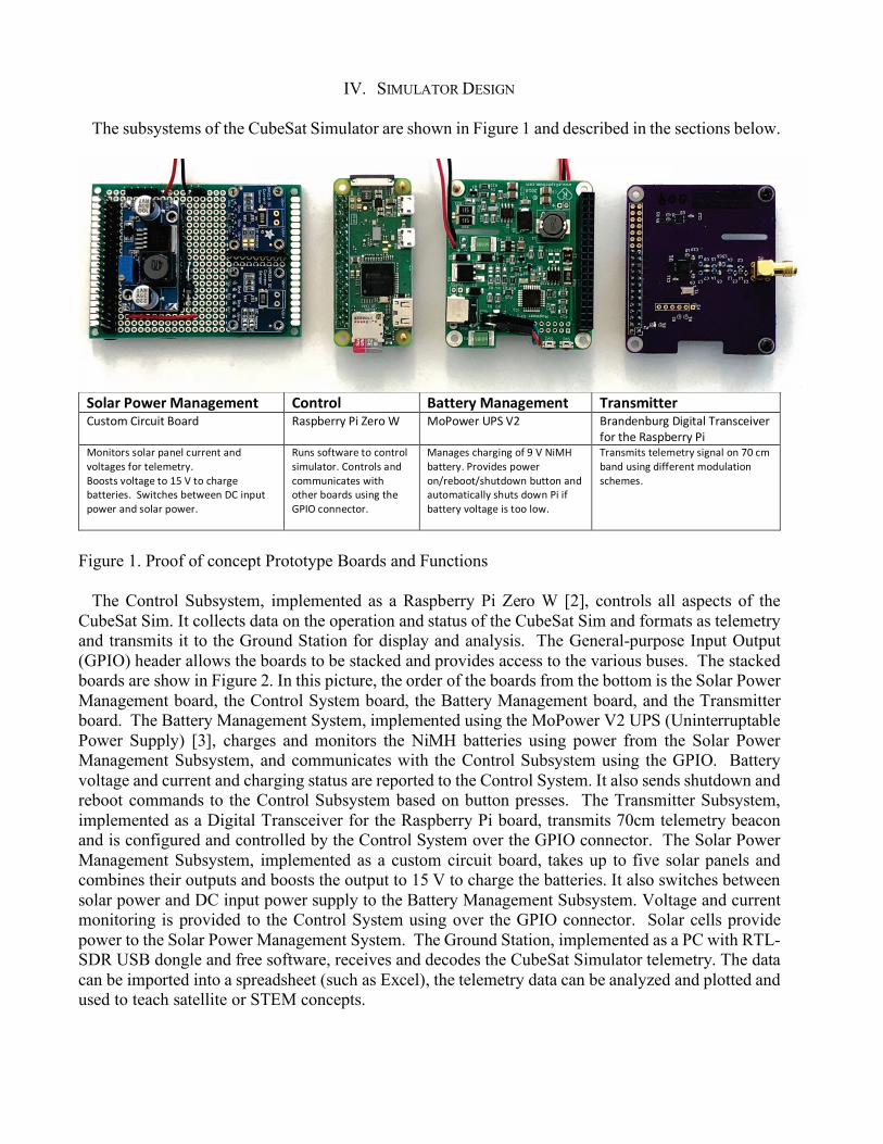
The subsystems of the CubeSat Simulator are shown in Figure 1 and described in the sections below.
!"#$%&'"()%&*$+$,)-)+.& /"+.%"#& 0$..)%1&*$+$,)-)+.&& 2%$+3-4..)%&!"#$%&'!()*"($'+%,)-' .,#/01))2'3('41)%'5' 6%3%71)'839':;' +),<-1<0")='>(=($,?'@),<#*1(A1)'
B%)'$C1'.,#/01))2'3('6%<($%)#'#%?,)'/,<1?'*"))1<$',<-'A%?$,=1#'B%)'$1?1&1$)2D'+%%#$#'A%?$,=1'$%'EF':'$%'*C,)=1'0,$$1)(1#D''97($*C1#'01$711<'>!'(</"$'/%71)',<-'#%?,)'/%71)D'
."<#'#%B$7,)1'$%'*%<$)%?'#(&"?,$%)D'!%<$)%?#',<-'*%&&"<(*,$1#'7($C'%$C1)'0%,)-#'"#(<='$C1'G3HI'*%<<1*$%)D'
6,<,=1#'*C,)=(<='%B'J':'K(6L'0,$$1)2D'3)%A(-1#'/%71)'%<M)10%%$M#C"$-%7<'0"$$%<',<-',"$%&,$(*,??2'#C"$#'-%7<'3('(B'0,$$1)2'A%?$,=1'(#'$%%'?%7D''
@),<#&($#'$1?1&1$)2'#(=<,?'%<'NO'*&'0,<-'"#(<='-(BB1)1<$'&%-"?,$(%<'#*C1&1#D'''
Figure 1. Proof of concept Prototype Boards and Functions
The Control Subsystem, implemented as a Raspberry Pi Zero W [2], controls all aspects of the CubeSat Sim. It collects data on the operation and status of the CubeSat Sim and formats as telemetry and transmits it to the Ground Station for display and analysis. The General-purpose Input Output (GPIO) header allows the boards to be stacked and provides access to the various buses. The stacked boards are show in Figure 2. In this picture, the order of the boards from the bottom is the Solar Power Management board, the Control System board, the Battery Management board, and the Transmitter board. The Battery Management System, implemented using the MoPower V2 UPS (Uninterruptable Power Supply) [3], charges and monitors the NiMH batteries using power from the Solar Power Management Subsystem, and communicates with the Control Subsystem using the GPIO. Battery voltage and current and charging status are reported to the Control System. It also sends shutdown and reboot commands to the Control Subsystem based on button presses. The Transmitter Subsystem, implemented as a Digital Transceiver for the Raspberry Pi board, transmits 70cm telemetry beacon and is configured and controlled by the Control System over the GPIO connector. The Solar Power Management Subsystem, implemented as a custom circuit board, takes up to five solar panels and combines their outputs and boosts the output to 15 V to charge the batteries. It also switches between solar power and DC input power supply to the Battery Management Subsystem. Voltage and current monitoring is provided to the Control System using over the GPIO connector. Solar cells provide power to the Solar Power Management System. The Ground Station, implemented as a PC with RTL-SDR USB dongle and free software, receives and decodes the CubeSat Simulator telemetry. The data can be imported into a spreadsheet (such as Excel), the telemetry data can be analyzed and plotted and used to teach satellite or STEM concepts.

Each of these subsystems is described in more detail in the following sections. The interconnection of the subsystems is shown in the block diagram of Figure 3.
!Figure 2. Proof of concept Prototype Stack
Figure 3. CubeSat Simulator Subsystem Block Diagram
A.! Raspberry Pi Zero W
The Raspberry Pi Zero W is a small form factor and low power usage version of the popular
Raspberry Pi single board computer, running the Raspbian Stretch version of Debian Linux. It is similar to the common Raspberry Pi 3B and 3B+ but is about half the width and does not have an ethernet port or full-sized USB ports. Instead, it has a micro USB port and a small HDMI port. The Pi Zero W does have Wi-Fi and Bluetooth connectivity. We need to disable the Bluetooth functionality as it changes the clock rate of the Raspberry Pi when the UART is enabled, causing communication issues with the Digital Transceiver for the Raspberry Pi board. The Raspberry Pi does not have a hard drive. Instead, storage is a micro SD card of at least 16GB. During the initial install and configuration, a Raspberry Pi unfortunately needs to be connected to a monitor, keyboard, and mouse. As a result, adapters for the micro USB and small HDMI are needed. However, once the Wi-Fi is configured and SSH (Secure Shell remote login) is enabled, the Pi can be accessed using a PC (running Putty on a PC or ssh on a Mac or Linux) over the network. The Pi Zero W runs on 5 V power which can be provided
via the micro USB or via the GPIO. The Pi Zero draws about 120 mA, compared to about 400 mA for the Pi 3B+.
The Raspberry Pi General-Purpose Input Output (GPIO) interface is used interface with the other
boards in the CubeSat Sim. In order to connect multiple GPIO devices to a Pi, either a GPIO expansion board (such as a 3-in-1 expansion board), or the GPIO headers need to be replaced with stackable headers. Stackable headers provide a better form factor without having to offset each board with the expansion board. The Pi Zero W usually comes without the GPIO header pins installed, making it easy to instead install a stackable header. We removed the GPIO header pins on the MoPower UPS V2 board and replaced it with a stackable header.
The GPIO contains the three buses used to communicate with various modules: the UART, the I2C
bus, and the SPI bus. The use of each of these buses will be described by the subsystem that uses them to communicate with the Pi.
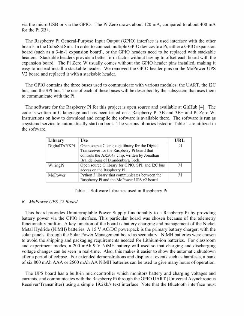
The software for the Raspberry Pi for this project is open source and available at GitHub [4]. The
code is written in C language and has been tested on a Raspberry Pi 3B and 3B+ and Pi Zero W. Instructions on how to download and compile the software is available there. The software is run as a systemd service to automatically start on boot. The various libraries listed in Table 1 are utilized in the software.
Library Use URL DigitalTxRXPi Open source C language library for the Digital
Transceiver for the Raspberry Pi board that controls the AX5043 chip, written by Jonathan Brandenburg of Brandenburg Tech.
[5]
WiringPi Open source C library for GPIO, SPI, and I2C bus access on the Raspberry Pi
[6]
MoPower Python 3 library that communicates between the Raspberry Pi and the MoPower UPS v2 board
[3]
Table 1. Software Libraries used in Raspberry Pi
B.! MoPower UPS V2 Board
This board provides Uninterruptable Power Supply functionality to a Raspberry Pi by providing battery power via the GPIO interface. This particular board was chosen because of the telemetry functionality built-in. A key function of the board is battery charging and management of the Nickel Metal Hydride (NiMH) batteries. A 15 V AC/DC powerpack is the primary battery charger, with the solar panels, through the Solar Power Management board as secondary. NiMH batteries were chosen to avoid the shipping and packaging requirements needed for Lithium-ion batteries. For classroom and experiment modes, a 200 mAh 9 V NiMH battery will used so that charging and discharging voltage changes can be seen in real-time. Also, this makes it easier to show the automatic shutdown after a period of eclipse. For extended demonstrations and display at events such as hamfests, a bank of six 800 mAh AAA or 2500 mAh AA NiMH batteries can be used to give many hours of operation.
The UPS board has a built-in microcontroller which monitors battery and charging voltages and
currents, and communicates with the Raspberry Pi through the GPIO UART (Universal Asynchronous Receiver/Transmitter) using a simple 19.2kb/s text interface. Note that the Bluetooth interface must
be disabled or the clock rate changes when the UART is enabled, making the Digital Transceiver board unreachable. The Raspberry Pi runs Python 3 code that communicates with the board and safely shuts down the Raspberry Pi when the battery voltage drops below 7 V. This avoids file corruption on the SD card that is common if the Pi loses power suddenly.
A momentary push button switch is also provided to reboot (press) or shutdown or startup (press
and hold for 5 seconds) the Pi. The microcontroller can also be programmed for certain events. We use this functionality to automatically shutdown the Pi after an extended period of eclipse, and to start up the Pi from a shutdown state when the RBF pin is removed and the solar panels are illuminated for a period of time. In addition, the MoPower board has four 10-bit analog inputs (0 – 1.1 V) which could be used to gather additional telemetry information from sensors in the future.
C.! Digital Transceiver for the Raspberry Pi Board
The Digital Transceiver for the Raspberry Pi board is a transmitter/receiver for various digital modulation schemes based on the AX5043 chip. The board is produced by Brandenburg Tech [7]. The drivers and API library are available on GitHub [5].
The board supports both the I2C (Inter-Integrated Circuit) interface and the SPI (Serial Peripheral
Interface) but only the SPI interface is used in the current code. The board supports a wide range of data rates and modulation schemes. In the initial proof of concept prototype, two modes are utilized: CW (Continuous Wave, i.e. Morse code, also known as On-Off Keying or OOK) and 1200 bps AFSK (Audio Frequency Shift Keying) with X.25 packet formatting. The transmitter is configured to use the 70cm amateur radio band.
D.! Solar Power Management Board
Power to the CubeSat in flight mode is provided by the batteries and the solar panels. For the 1U model, five 65mm by 65 mm 5.5 V 110 mA panels are used, mounted on the +X, -X, +Y, -Y, and +Z sides. For the model with solar panel wings, two 160 mm x 70 mm 7.2 V 200 mA panels are mounted on the wings. Under room illumination, minimal power is delivered by the solar panels; however, a 250 W halogen work lamp placed about 10cm away produces about half the rated power for indoor usage. Placing the CubeSat Simulator on a small motorized turntable spinning at around 4 r.p.m. next to a work lamp can simulate a CubeSat rotating in the sun.
On the +Z side (top) of the CubeSat Sim, there are a number of controls and switches and a quarter-
wave antenna that connects via a 90-degree adapter and an SMA cable to the Digital Transceiver board. A barrel jack, 5.5 mm x 2.1 mm center positive, is provided for charging the NiMH batteries with 12 - 15 V DC input, such as from an AC power pack. The Remove Before Flight (RBF) pin switch is implemented as a 3.5 mm TRRS (Tip Ring Ring Sleeve) plug and jack. To switch the source of power between the DC jack and the solar panels, we use the two switches in the jack that are open when a 3.5 mm plug is plugged in, and closed when the plug is unplugged. When plugged in, the input power to the MoPower UPS is the DC Power Input jack. When unplugged, the input power to the MoPower UPS is the output of the Solar Power Management board. The push button switch is wired to SW3 on the MoPower board, and is used to reboot, shutdown, and startup the CubeSat Sim.
Each solar panel on the CubeSat Sim is connected together through a 1N5817 Schottky barrier diode
rated at 20 V and 1 A to prevent reverse current flow. The 1N5817 was chosen for its low forward

voltage drop of about 0.45 V. Each panel’s current and voltage is monitored using an Adafruit INA217 board that uses the I2C bus (Inter-Integrated Circuit, pronounced I-squared-C) to communicate with the Raspberry Pi. The Raspberry Pi has two I2C buses, available on the GPIO interface, in which the Pi acts as the bus master. A DC-DC Adjustable step-up power converter module [8], based on the ML6009 chip, acts as a boost converter circuit, to increase the 5.5 V from the solar panels to 15 V needed for the MoPower board to charge the NiMH batteries.
E.! Ground Station
The ground station can be any radio receiver capable of receiving FM and CW on the 70cm band. Since a PC is required to decode the telemetry, a great option is to use a Software Defined Radio (SDR) dongle such as an RTL-SDR [9] ($20 on Amazon.com) or the FUNcube Dongle made by AMSAT-UK [10] and a PC. Any SDR software could be used including the freeware SDR# (pronounced SDR sharp) [11] or HDSDR [12], or the open source Gqrx [13]. Figures 4 and 5 show SDR# tuning the CW and AFSK telemetry.
Other software is needed to decode the telemetry information. For the CW telemetry, there are
various decoding programs. For the AFSK, the open source Qtmm AFSK 1200 [14] works well. Note that some kind of speaker-to-microphone audio patching software is needed to pipe the audio output from the SDR software into the microphone input of the decoding software. For Windows, we have used VB-CABLE Virtual Audio Device, which is licensed as donationware [15]. The raw telemetry is then copy and pasted into a spreadsheet to decode and display the actual telemetry values. For fun, we chose the AO-7 telemetry format (e.g. hihi 1aa 1bb 1cc 1dd 2ee … where aa, bb, cc, and dd are two decimal digits that encode channel 1 data, etc,). Other formats can be added in the future, providing “emulation” for other satellites.
Note that the spreadsheet that we use is a modification of the actual “Morse Code Telemetry Frame
Decoder for AMSAT-OSCAR-7” by Jan King, W3GEY, and Jim White, WD0E, as shown in Figure 6. Formulas added to the spreadsheet take pasted telemetry frames and separates (parses) them into channels for display, which are then decoded into actual values. Most of the telemetry values in the AO-7 format are used by the CubeSat Simulator.
This ground station option requires the installation of SDR dongle drivers on a user’s PC, which is
a manual process. There are some possible ways to avoid doing this. One would be to use a Raspberry Pi 3B or 3B+ with either a Digital Transceiver for the Raspberry Pi board configured to act as a receiver, or a Pi with an RTL-SDR dongle. This Raspberry Pi could be used directly with a monitor, keyboard and mouse, or it could be accessed via a PC using a VNC connection over a network, or a direct USB serial connection. Another interesting variant would be to build a ground station with a Linux Wi-Fi router (such as an old Linksys) running a rtl_tcp server [17] with an RTL-SDR dongle. The rtl_tcp server software allows any PC connected to the Wi-Fi network to connect to the RTL-SDR radio using SDR# and receive the IQ (In-phase and Quadrature) data in a stream which they can then demodulate and decode on their own PC. This would also have the advantage of a Wi-Fi network that the CubeSat Sim would always connect to, making access and configuration easy. Plugging in the Ethernet of the Linux Wi-Fi router to the internet would allow software updates and even remote access to the CubeSat Sim. This same approach that allows users of SDR# to connect to the server and demodulate and decode on their own PC could allow multiple participants in a room to do this, or even for remote participants on a web conference, for example, if the network access was properly configured.
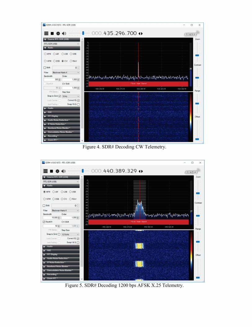
!Figure 4. SDR# Decoding CW Telemetry.
!!
Figure 5. SDR# Decoding 1200 bps AFSK X.25 Telemetry.
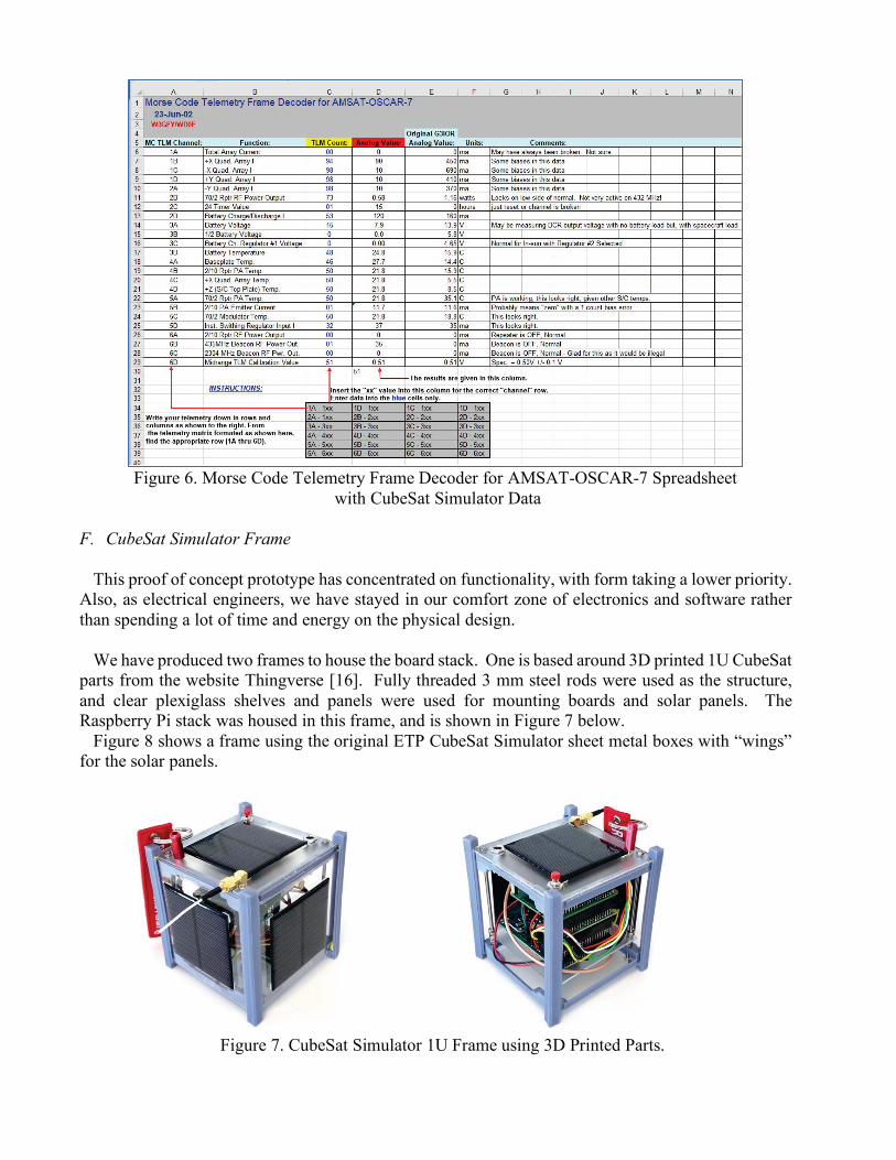
Figure 6. Morse Code Telemetry Frame Decoder for AMSAT-OSCAR-7 Spreadsheet
with CubeSat Simulator Data
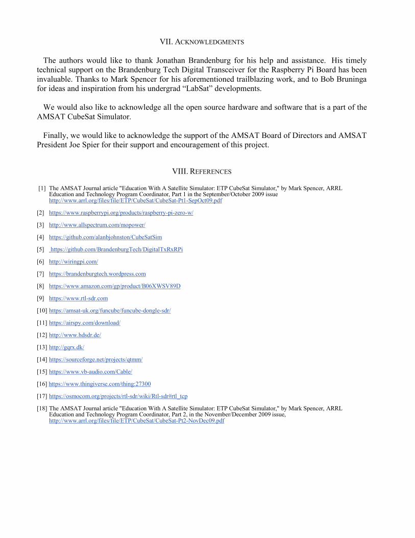
F.! CubeSat Simulator Frame This proof of concept prototype has concentrated on functionality, with form taking a lower priority.
Also, as electrical engineers, we have stayed in our comfort zone of electronics and software rather than spending a lot of time and energy on the physical design.
We have produced two frames to house the board stack. One is based around 3D printed 1U CubeSat
parts from the website Thingverse [16]. Fully threaded 3 mm steel rods were used as the structure, and clear plexiglass shelves and panels were used for mounting boards and solar panels. The Raspberry Pi stack was housed in this frame, and is shown in Figure 7 below.
Figure 8 shows a frame using the original ETP CubeSat Simulator sheet metal boxes with “wings” for the solar panels.
Figure 7. CubeSat Simulator 1U Frame using 3D Printed Parts.

Figure 8. CubeSat Simulator Winged Frame using Original ETP CubeSat Simulator Sheet Metal Frame.
G.! Cost
The approximate cost of making the CubeSat Sim is shown in Table 2.
Part Qty Cost Total Digital Transceiver for the Raspberry Pi board 1 $60.00 $60.00 MoPower V2 UPS board for Pi 1 $60.00 $60.00 Adafruit INA219 DC current/voltage sensor board 5 $10.00 $50.00 Solar Cells, 5.5 V,110 mA 65 mm x 65 mm 5 $5.00 $25.00 Raspberry Pi Zero W CPU 1 $20.00 $20.00 RTL-SDR USB dongle for PC 1 $20.00 $20.00 16 GB SD Card with Raspbian Stretch 1 $18.00 $18.00 AC/DC power adapter 15 V 1 $13.00 $13.00 Clear acrylic sheet 8 x 10 2 $5.00 $10.00 SMA M-M Cable 1 $7.00 $7.00 SMA Cable M-F 1 $6.00 $6.00 2x40 pin stackable header 2 $2.75 $5.50 SMA Antenna 433 MHz 1 $5.00 $5.00 9 V NiMH battery 1 $5.00 $5.00 Various hardware 1 $5.00 $5.00 TRRS plug and jack for RBF switch 1 $5.00 $5.00 SMA 90 degree M-F 1 $3.00 $3.00 1N5817 Schottky diode 5 $0.45 $2.25 DC-DC Boost Converter Module XL6009 1 $2.00 $2.00 Momentary pushbutton switch 1 $1.50 $1.50 Barrel Jack for AC/DC charger 1 $0.75 $0.75 TOTAL $324.00
Table 2. Cost of Components for the Prototype.

V. APPLICATIONS AND USES OF THE CUBESAT SIMULATOR
Various educational exercises with a CubeSat Simulator are described in Mark Spencer’s paper [18]. This new CubeSat Sim can be used in many of these exercises. In addition, we anticipate that the CubeSat Simulator will be useful to teams planning to build a CubeSat to gain experience. Also, we hope that emulation for additional satellites will provide practice and training in copying telemetry from new and existing satellites in a classroom setting. We plan to write an article in the AMSAT Journal describing activities and exercises with the CubeSat Simulator.
There is one interesting way in which users without an RTL-SDR radio and antenna can participate
in demos using only an internet connected PC. If a remotely accessible SDR server is receiving the CubeSat Simulator transmissions, other users can connect to the server and then do their own decoding of the telemetry. For example, the rtl_tcp [17] server software that allows users of SDR# to connect to the server and demodulate and decode on their own PC could allow multiple participants in a room to do this, or even for remote participants on a web conference, for example, if the network access was properly configured.
Currently, the CubeSat Sim supports two telemetry modulation schemes: CW and 1200 bps AFSK
X.25. In both cases, the telemetry is formatted in AO-7 format. In the future, support for additional telemetry modulation schemes and telemetry formats can be added. One interesting thing to do in the future would be to implement the Data Under Voice (DUV) 200 bps FSK telemetry used by the AMSAT Fox satellites. This “Fox emulation mode” would allow the use of the FoxTelem software to decode the telemetry. Also, in the future, developers of a new CubeSat could contribute an emulation mode for an upcoming satellite. This would allow amateurs to practice decoding telemetry and using the telemetry analysis tools before launch, avoiding the scramble after a CubeSat is launched and potential loss of initial telemetry data. At AMSAT, we can also ensure that we provide a “GOLF emulation mode” as our next generation of satellites are developed, providing excitement and training on telemetry reception prior to launch.
VI. NEXT STEPS
Our next steps are to get community feedback on the design and implementation. We are particularly looking for improvements for the frame, to make it sturdy and easy to build.
We plan to fully document hardware and software online and in the AMSAT Journal so that others
can build their own. We are also looking for Beta testers to test it out in public demonstrations and classroom exercises and provide feedback. Please contact us directly if you are interested. Teachers are encouraged to write and share example Lesson Plans at specific age and grade-appropriate levels to help educators incorporate the simulator in classes and extracurricular activities.
AMSAT also plans to build a number of AMSAT owned CubeSat Simulators and make them
available to educators to use by shipping them around. To support this, we will document presentations and activities to be used with the CubeSat Sim. Ultimately, we hope to grow a community of satellite simulator enthusiasts who continue to improve and extend the CubeSat Sim, adding additional functionality and satellite emulation modes.
VII. ACKNOWLEDGMENTS
The authors would like to thank Jonathan Brandenburg for his help and assistance. His timely technical support on the Brandenburg Tech Digital Transceiver for the Raspberry Pi Board has been invaluable. Thanks to Mark Spencer for his aforementioned trailblazing work, and to Bob Bruninga for ideas and inspiration from his undergrad “LabSat” developments.
We would also like to acknowledge all the open source hardware and software that is a part of the AMSAT CubeSat Simulator.
Finally, we would like to acknowledge the support of the AMSAT Board of Directors and AMSAT
President Joe Spier for their support and encouragement of this project.
VIII. REFERENCES
[1] The AMSAT Journal article "Education With A Satellite Simulator: ETP CubeSat Simulator," by Mark Spencer, ARRL
Education and Technology Program Coordinator, Part 1 in the September/October 2009 issue http://www.arrl.org/files/file/ETP/CubeSat/CubeSat-Pt1-SepOct09.pdf
[2] https://www.raspberrypi.org/products/raspberry-pi-zero-w/ [3] http://www.allspectrum.com/mopower/ [4] https://github.com/alanbjohnston/CubeSatSim [5] https://github.com/BrandenburgTech/DigitalTxRxRPi [6] http://wiringpi.com/ [7] https://brandenburgtech.wordpress.com [8] https://www.amazon.com/gp/product/B06XWSV89D [9] https://www.rtl-sdr.com [10] https://amsat-uk.org/funcube/funcube-dongle-sdr/ [11] https://airspy.com/download/ [12] http://www.hdsdr.de/ [13] http://gqrx.dk/ [14] https://sourceforge.net/projects/qtmm/ [15] https://www.vb-audio.com/Cable/ [16] https://www.thingiverse.com/thing:27300 [17] https://osmocom.org/projects/rtl-sdr/wiki/Rtl-sdr#rtl_tcp [18] The AMSAT Journal article "Education With A Satellite Simulator: ETP CubeSat Simulator," by Mark Spencer, ARRL
Education and Technology Program Coordinator, Part 2, in the November/December 2009 issue, http://www.arrl.org/files/file/ETP/CubeSat/CubeSat-Pt2-NovDec09.pdf