the analyzing method of hydrogen trapping sites in metal ...formally structure in metal crystals...
TRANSCRIPT
Analyzing Method of Hydrogen Trapping Sites in Metal Crystals and the Relationship between Surface Defects and Hydrogen Absorption
Gen KatanoKEK, High Energy Accelerator Research Organization, Japan
Introduction about researches of Hydrogen Embritllement
Principal and Experimental procedure of Tritium Autoradiography
Results of Autoradiography observation High-Strength Steel and Ni3Al
Investigation of trapped hydrogen feature
Summary

Four steps of investigation of the cause of Hydrogen Embrittlement
• Where are hydrogen paths? Hydrogen can enter into metal along tunnel structure at grain boundary, matrix or other routes.
• What role does hydrogen play at the cracking?
• What kinds of hydrogen trap sites exist? What is the hydrogen bonding energy?
• How to prevent hydrogen embrittlement? Improvement?
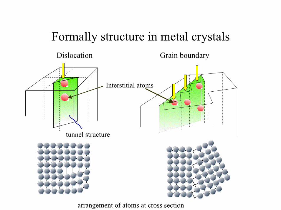
Formally structure in metal crystalsDislocation Grain boundary
tunnel structure
Interstitial atoms
arrangement of atoms at cross section

Cracking mechanism supported by hydrogen
stress stress
1 3
Slip
face
Hydrogen gatheringOther slip face is active.Cracking direction change.
Makes atom dislocation.easier
Slip face
A slip face is active.
2
One after another cracking direction change And cracking progress.
4
Slip face

Approaches to solve the problem of Hydrogen Embrittlement
Gathering
Cracking
Cracking process
Hydrogen location analysis
Analysis of Hydrogen dynamics and bonding Energy to trapping sites
Computer simulationAutoradiographyLuminographyMicroprint MethodChannelling
crack Observation
Hydrogen Embrittlement has two stages
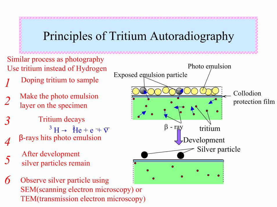
Silver particleDevelopment
tritiumβ - ray
Exposed emulsion particlePhoto emulsion
Collodion protection film
Use tritium instead of Hydrogen
Tritium decays
β-rays hits photo emulsion
After development silver particles remain
H → He + e + ν3 3 __
Observe silver particle using SEM(scanning electron microscopy) or TEM(transmission electron microscopy)
Principles of Tritium Autoradiography
Similar process as photography
1 Doping tritium to sample
Make the photo emulsion layer on the specimen2
3
456

Typical photograph of the Tritium Autoradiography
SEM ImageObservation of Autoradiography on High Strength Steel

Experimental procedure of doping tritium into metal structure
+
-
sample
Copper wire
Pt anode
DC power supplycathod
NaOH aqueous solution (0.10 kmol/m )3
Tritium decay rate 3.7 10 Bq/m 315
Current density 25A/m2
Dorping time 2.0 h
e
e
e
e
e
e
e
e
OxygenHydrogenTritium
Gas bubble
2H + 2e → H2↑H + e → H (in Metal)
++
__
(HHS or Ni3Al)
Electrochemical cathodic charging
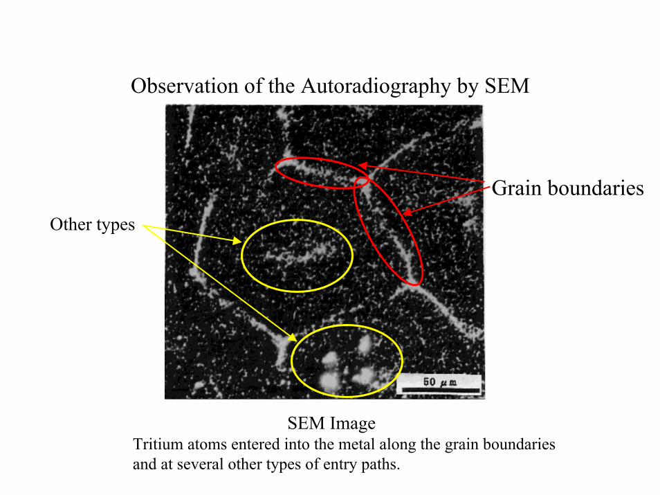
Observation of the Autoradiography by SEM
Grain boundariesOther types
SEM ImageTritium atoms entered into the metal along the grain boundaries and at several other types of entry paths.

SEM and TEM
Electron beam
Other phases
Grain boundariesDislocations
Electron beam
With SEM we can only get hydrogen distribution Information. With TEM
we can see not only silver particles but also metal structure.This method have no information
about internal structure.

Observation of the Autoradiography by TEM on HSSs
Silver grain
Ferrite
Ferrite
Ferrite
Cem
entite
Cem
entite
Cem
entite
TEM Image (photo) TEM Image (Enhanced)
Tritium atoms entered the metal along the boundaries line of “Sandwich structure”.
In shown photo, we can see that hydrogen enters HSS at boundaries and in Cementite structure.

Ferrite-ferrite boundaries trap many hydrogen atoms
Boundary line
Ferrite
Silver particle

Structure of intermetallic compound Ni3Al
Ni atomsAl atoms
Octahedral site
Tetrahedral site
Volume large in comparison to Tetrahedral site
L12 type crystal structure has two type interstitial sites.

Observation of trapped hydrogen distribution in Ni3Al
Grain boundaryTrapped tritium is uniformly distribution over the sample (not only at grain boundary). Silver particle

Hydrogen in Ni3Al dislocation
Dislocation lines
Silver particle
Dislocation trap tritium !

Hydrogen in damaged structure
Ni3Al structure was “damaged” by high energy (4MeV) Ni atoms.Damaged structure was doped by tritium and autoradiography was made.
Damaged structure traps hydrogen well !
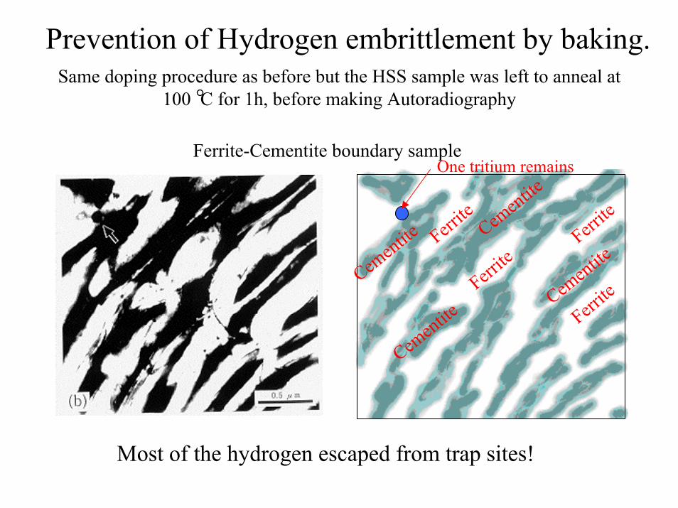
Same doping procedure as before but the HSS sample was left to anneal at 100 C for 1h, before making Autoradiography
Prevention of Hydrogen embrittlement by baking.
Ferrite
Ferrite
Ferrite
Ferrite
Cementite
Cementite
Cementite
Cementite
Ferrite-Cementite boundary sampleOne tritium remains
Most of the hydrogen escaped from trap sites!

Anneal 100 C for 1h, before making Autoradiography
Ferrite-ferrite boundary sample
All tritium left the sample
Only one silver particle cannot be seen in this area. Ferrite
Silver particle

Summary of Autoradiography observation at High-Strength Steel
1
2
3
We observed hydrogen atoms trapping.grain boundaries ferrite-cementite boundarycementiteferrite-ferrite boundary.
Boundary structure traps many hydrogen atoms, but they leave after annealing at 100 C for 1h.
Therefore bonding energy is low at these trap sites.

Ni3Al
uniform
dislocations
damaged structure
High-strength steel
Non-uniform
boundaries of “sandwich structure”
grain boundaries
Hydrogen distribution
Hydrogen trap site
bcc structure fcc structure

Two types trapping sites
Low bonding energy trapping site
100 C 300 - 400 CHigh bonding energy trapping site
Typical peaks of hydrogen in thermal analysisby N.Suzuki etc.
Suggestion to Niobium or metals in general
Grain boundaries are important to hydrogen path and trapping sites by bcc metals.
Metal crystal have plural hydrogen trapping sites.
Low energy bonding sites release hydrogen easily.Therefore these hydrogen have greatly effect to hydrogen gathering.
Thank you very much for your kind attention.