the anatomical and radiological …repository-tnmgrmu.ac.in/8762/1/220201118chandan.pdfand take time...
TRANSCRIPT

THE ANATOMICAL AND RADIOLOGICAL
RELATIONSHIP BETWEEN THE PARS
INTERARTICULARIS AND THE PEDICLE IN
THE LUMBAR SPINE – IMPLICATIONS FOR
PEDICLE SCREW INSERTION
Dissertation submitted to the Tamil Nadu Dr.M.G.R Medical
University in partial fulfillment of the requirement for the
M.S Degree Examination Branch II (Orthopaedic Surgery)
May 2018

CERTIFICATE
This is to certify that the dissertation entitled “The Anatomical And Radiological
Relationship Between The Pars Interarticularis And The Pedicle In The Lumbar Spine
– Implications For Pedicle Screw Insertion.” is original work done by
Dr. Chandan. N
Done under my guidance towards the M.S Branch (Orthopaedics) Degree
Examination of the Tamilnadu Dr. MGR Medical University, Chennai to be held in
May 2018.
Signature:
Head of Department
Dr. V.T.K. Titus
Professor & Head of Unit
Orthopaedics
Christian Medical College
Vellore- 632004
Principal:
Christian Medical College
Vellore -632004

CERTIFICATE
This is to certify that the dissertation entitled “The Anatomical And Radiological
Relationship Between The Pars Interarticularis And The Pedicle In The Lumbar Spine
– Implications For Pedicle Screw Insertion.” is original work done by
Dr. Chandan. N
Done under my guidance towards the M.S Branch (Orthopaedics) Degree
Examination of the Tamilnadu Dr. MGR Medical University, Chennai to be held in
May 2018.
Signature
GUIDE:
Dr Kenny S David
Professor and Head of Unit
Spinal Disorders Surgery
Christian Medical College
Vellore -632004

DECLARATION CERTIFICATE
This is to declare that the dissertation titled “The anatomical and radiological relationship
between the pars interarticularis and the pedicle in the lumbar spine – implications for pedicle
screw insertion”, in the department of Orthopedics is my own work, done under the guidance
of Dr. Kenny S. David, Professor and Head Spinal Disorders Unit, submitted in the partial
fulfillment of the rules and regulation for the M.S Orthopedics degree examination of the
Tamilnadu Dr. M.G.R Medical University, Chennai to be held in May 2018
.
Dr. Chandan. N
M.S Post Graduate Registrar
Department of Orthopaedics
Christian Medical College,
Vellore.

ACKNOWLEDGEMENTS
I thank God for His enabling grace that helped me in completing this work all the
people who helped in this process.
I express my sincere thanks and heartfelt gratitude towards Dr. Kenny S. David,
Professor & Head, Spinal Disorders, for being my guide and directing me to work on
this unique topic as a part of my thesis. He has always been patient enough to listen
and take time out of his busy schedule towards working on this project. I had great
time working along with him and thankful for the timely help he extended when it was
needed. He constantly supported and directed me towards the completion of the thesis
in spite of my short comings, and I shall always be grateful to him.
I shall remain indebted to Dr. Dr.Suganthy Rabi Professor & Head, Department of Anatomy
for providing me the needed cadaver specimens, place and freedom to work, without her help
it would have been impossible to proceed further in this project.
I also extend my sincere thanks to Dr.Madhavi Assistant Professor and Dr Soumya
Susan Regi Assistant Professor from the Department of Radiology for their efforts in
providing with the radiological measurements in spite of their busy schedule.
I also extend my gratitude to Dr. Arul Parathasarathy RM Fellow, Spinal Disorders Surgery
Unit. His help in dissecting the cadaveric specimens is noteworthy. It was a wonderful
experience doing the study with him and something I shall fondly remember.

I also thank Dr Venkatesh, Dr. Rohit Amritanand and Dr Justin in providing me useful
insight into my study and providing the necessary constructive criticism and moral
support.
It was my privilege to have received training from various experienced faculty from
the Department of Orthopaedics for their amazing advice and teaching throughout the
training period.
I thank my colleagues, seniors and juniors for their constant support.
And last, but not the least my parents, sisters and special mention of my wife
Dr.Rebecca for her constant encouragement and prayers.

Contents
AIM: ............................................................................................................................... 8
OBJECTIVE: .................................................................................................................. 8
INTRODUCTION: ......................................................................................................... 9
LITERATURE REVIEW ............................................................................................. 24
METHODOLOGY ....................................................................................................... 39
RESULTS: .................................................................................................................... 53
DISCUSSION ............................................................................................................... 68
CONCLUSIONS .......................................................................................................... 77
LIMITATIONS: ........................................................................................................... 77
BIBLOGRAPHY .......................................................................................................... 78
ANNEXURES .............................................................................................................. 87
SCANNED COPY OF IRB LETTER ...................................................................... 87
THESIS DATA ......................................................................................................... 88
AIM:
To describe the relationship between pars interarticularis with the pedicle in lumbar
vertebra and to use that relationship as a consistent landmark for pedicle screw insertion
between T12 and L4 vertebra.
OBJECTIVE:
To demonstrate that the lateral border of the pars interarticularis can be used as a
consistent and reproducible anatomical landmark between T12 to L4 vertebra to guide
pedicle screw placement.

INTRODUCTION:
Anatomy of Lumbar Spine:
"Lumbar" is derived from the Latin word "lumbus," meaning lion and is designed for
both stability and flexibility - lifting, twisting, and bending.
The lumbar spine is made up of 5 vertebral segments, termed lumbar segment (L1-
L5).
Characteristics of Lumbar Spine:
The five vertebrae of the lumbar spine (L1-L5) are the biggest and unfused vertebrae
in the vertebral column, enabling them to support the weight of the entire torso.
Through the lower segments, L4-L5 and L5-S1, most of the body weight gets
transmitted and are more prone for degenerative changes.

The lumbar spine forms the lumbosacral joint at sacrum (L5-S1) this allows for
considerable rotation, so that the pelvis and hips may swing when walking and
running.
The vertebral bodies are large and kidney-shaped. They are deeper anteriorly than
posteriorly, producing the lumbosacral angle (the angle between the long axis of the
lumbar region and that of the sacrum).
Parts of lumbar vertebrae:
Transverse processes are long and slender.
Articular processes have nearly vertical facets.
Spinous processes are short and broad.
Accessory processes can be found on the posterior aspect of the base of each
transverse process. They act as sites of attachment for deep back muscles.
Mammillary processes can be found on the posterior surface of each superior articular
process. They act as sites of attachment for the muscles.

Joints:
There are two types of joint in the lumbar spine.
Between vertebral bodies – adjacent vertebral bodies are joined by intervertebral
discs, made of fibrocartilage. This is a type of cartilaginous joint

Between vertebral arches – formed by the articulation of superior and inferior articular
processes from adjacent vertebrae. It is a synovial type joint.
Ligaments:
The joints of the lumbar vertebrae are inter connected by several ligaments. They can
be divided into two groups; those present throughout the vertebral column and those
unique to the lumbar spine.
Anterior and posterior longitudinal ligaments: Long ligaments that run the length of
the vertebral column, covering the vertebral bodies and intervertebral discs.
Ligamentum flavum: Connects the laminae of adjacent vertebrae.
Interspinous ligament: Connects the spinous processes of adjacent vertebrae.
Supraspinous ligament: Connects the tips of adjacent spinous processes.

The lumbosacral joint (between L5 and S1 vertebrae) is strengthened by
the iliolumbar ligaments. These are fan-like ligaments radiating from the transverse
processes of the L5 vertebra to the pelvis
The vertebral foramen is triangular in shape through which neural elements pass
The spinal cord travels from the base of the skull through the spinal column and ends
at about T12-L1, where the thoracic spine meets the lumbar spine. At this junction
numerous nerve roots from the spinal cord continue down and branch out, forming the
“cauda equina" named for its resemblance to a horse tail.

T12-Thoracic Vertebra:
The twelfth thoracic vertebra (or the T12 vertebra) is the largest of the thoracic
vertebrae. T12 bears the most weight of any thoracic vertebra, making it the strongest
thoracic vertebra, but also more prone for injuries due to the transitional nature from
more rigid to more mobile segment of the spinal column. T12 vertebra has anatomical
features of both a thoracic and lumbar vertebra. Its structure is similar to the other
thoracic vertebrae, with a large column of bone known as the centrum (or vertebral
body) forms its anterior structure and a thin ring of bone known as the vertebral arch
forming its posterior structure.


The vertebral body is larger and wider in T12 than in the other thoracic vertebrae and
more closely resembles the vertebral bodies of the lumbar vertebrae.
It is flat on top and bottom, convex anteriorly, and slightly concave posteriorly.
The vertebral arch of T12 is thicker and stronger than its counterparts in the other
thoracic vertebrae and in many ways resembles the vertebral arches of the lumbar
vertebrae.
A pair of strong pedicles extends posteriorly from the vertebral body to begin the
neural arch.
Each pedicle contains a smooth, oval-shaped articular facet that forms a joint with the
12th pair of ribs.
Posterior to the pedicles are the transverse processes that extend laterally from the
vertebral arch.
Unlike the transverse processes of the superior thoracic vertebrae, those of T12 are
short; they do not form joints with the ribs; and they end in three tiny processes – the
superior, lateral and inferior tubercles which serve as attachments to the muscles.
The thin laminae continue the vertebral arch posteriorly from the transverse processes
until they unite in midline to form the spinous process.

The spinous process is considerably shorter, straighter, and thicker in T12 than it is in
the superior thoracic vertebrae, closely resembling the spinous process of the lumbar
vertebrae below.
Extending vertically from the vertebral arch are two pairs of articular processes that
form joints with the adjacent vertebra and helps in stabilizing the spine.
The superior articular processes extend superiorly to meet the inferior articular
processes of the T11 vertebra.
Each superior articular process resembles those of the thoracic vertebrae, ending in a
smooth, convex oval that corresponds with the concave oval of the inferior articular
process of T11.
The joints formed between T11 and T12 are termed as planar joints, and allow the
bones to glide along a plane relative to one another.

Inferiorly the T12, has a pair of inferior articular processes descends to meet the
superior articular processes of the L1 vertebra. The inferior articular processes
resemble those of the lumbar vertebrae, ending in smooth cylinders of bone that are
surrounded by cup-like ends of the superior articular processes of L1.
The joints formed between T12 and L1 are reinforced planar joints, which are less
mobile and more stable than the T11-T12 joints.

Pars Interarticularis:
Definition:
Pars Interarticularis (Latin-bridge between two joints) or pars in short is defined as
small segment of bone that connects superior and inferior facet joints in the vertebral
column.
In transverse plane pars lies between the lamina and the pedicle and in axial view it
forms the bony mass that lies between the superior and inferior facet joints.
In the cervical spine, pars interarticularis is commonly referred to as the lateral mass,
and in the thoroco-lumbar spine, it forms the location where the transverse processes
take their origin.
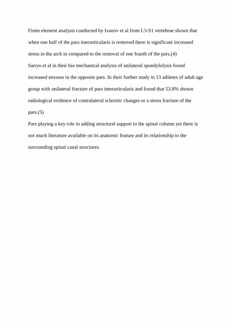
In radiographs of lumbar spine taken in anterior oblique view, pars represents the neck
of the imaginary Scottie dog; the Scottie dog's eye represents the pedicle, its nose
represents the transverse process, ear the superior articular facet and forelegs the
inferior articular facet, hind legs the spinous process respectively.

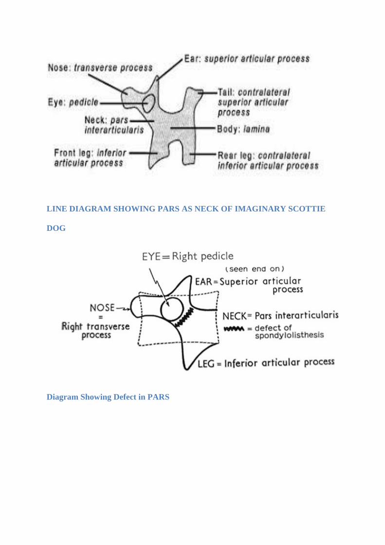
LINE DIAGRAM SHOWING PARS AS NECK OF IMAGINARY SCOTTIE
DOG
Diagram Showing Defect in PARS

Krenz et al studied the normal anatomy of the pars of 4th
and 5th
Lumbar vertebra in
seven cadaver specimens and described pars is made up of two dense cortical layers
antero-lateral and postero-medial; the antero-lateral being the thickest part (1). And
the trabeculae present in between the antero-lateral and postero-medial layers appear
to be stronger than in the rest of lamina which might be the reason that pars can
withstand considerable amount of stress.
Anatomically, pars forms the narrowest part of the bony arch, and Bio mechanically
pars is subjected to high stresses during adjacent segment movement in the vertebral
column and has its own important clinical implications. In a C2 Hangman’s type
fracture, the pars is the segment of the bone that fractures, and in lumbar spine, stress
fracture through the pars is termed as spondylolysis.
There are significant number of anatomical and morphological studies mostly focused
on the vertebral body, pedicles, spinal canal, and the relationship of the pedicles to
spinal canal. Till date there is limited data available regarding the pars interarticularis
and its relationship to the surrounding structures.
The role of pars interarticularis in maintaining the structural integrity of the vertebral
column is shown in various studies. Ranu et al analyzed the amount of stress on the
pars on in-tact and post laminectomy vertebra and found that the pars is subjected to
high stress and also shown to increase when the posterior elements are further
removed.(2)
Cyron et al shown that the there is increased susceptibility of the pars fracture when
subjected to repetitive stress in their study on intact lumbar spine.(3)
Finite element analysis conducted by Ivanov et al from L3-S1 vertebrae shown that
when one half of the pars interarticularis is removed there is significant increased
stress in the arch in compared to the removal of one fourth of the pars.(4)
Sairyo et al in their bio mechanical analysis of unilateral spondylolysis found
increased stresses in the opposite pars. In their further study in 13 athletes of adult age
group with unilateral fracture of pars interarticularis and found that 53.8% shown
radiological evidence of contralateral sclerotic changes or a stress fracture of the
pars.(5)
Pars playing a key role in adding structural support to the spinal column yet there is
not much literature available on its anatomic feature and its relationship to the
surrounding spinal canal structures.

LITERATURE REVIEW
A variety of disease conditions in the spine, congenital, degenerative, traumatic,
neoplastic, results in unstable spine which may lead to unrelenting pain being a
mechanical cause, nerve root compression or a progressive deformity which may not
be fully addressed by non-operative management there by requiring surgical
intervention
In order to address the above conditions fusion of spine has been the main stay of
treatment, and the most common indications being instability following a trauma,
spondylolisthesis causing significant back and leg pain, degenerative lumbar canal
stenosis, psuedoarthrosis of spine, tumors being primary or metastatic in nature
resulting in instability and neurological compromise when significant portion of
vertebral body is involved.
The concept of internal fixation of the spine has gained its significance over the
decades from the time of its introduction by Harrington which was used initially for
correction of deformity in scoliosis followed by trauma(6). Before the introduction of
Harrington instrumentation the pseudoarthrosis rate following scoliosis correction is
30% to 40%.(7) Following the use of Harrington instrumentation to treat scoliosis the
pseudoarthrosis rate was 1% to 15%.(8) The purpose of internal fixation of the spine
is to aid in stabilization, early fusion rates there by decreasing the pain and morbidity
associated with prolonged hospital stay and allowing early mobilization and
rehabilitation.

If the above goals can be achieved with limited risk and at affordable costs, such
intervention is considered safe and effective for the patient.
With regard to internal fixation of spine various systems have evolved over the period
of time starting from Harrington instrumentation, Luque sub-laminar wiring
technique(9), Hook fixation by Cortel and Dubousset and each of the instrumentation
had their own drawbacks Viz., neurological injury, Dural tears, hook disengagement,
wire breakage, canal violation, inability to provide three dimensional stability and in
addition the fixation mainly depends upon the presence of intact posterior elements.
The concept of pedicle and facet screw fixation was first reported in 1940’s by King
D(10) later Boucher(11) used in 1959 and more extensively used by Roy-Camille
et.al.,(12) Since then pedicle screw instrumentation is gaining its popularity as its use
increased fusion rates, enhanced rigidity, can be used in short and long segment fusion
and above all pedicle screw does not require intact posterior elements.
The pedicle is considered as the strongest part of the vertebral body where the
posterior elements of the spine converge to form a bony mass which attaches to the
anterior portion of the vertebral body. It is described as “Force Nucleus” of the
vertebra (13). Being the strongest portion pedicle is considered as ideal point force for
pedicle screw placement. When properly placed screw is used along with screw-rod or
screw-plate configuration the ability to apply compression, distraction and rotational
force across the spinal segments has been greatly increased in order to address various
deformities and clinical conditions.
Biomechanics studies have shown the constructs with properly placed screws in the
pedicle provide more rigidity compared with other systems of instrumentation(14–16).
In addition to rigid fixation pedicle screw constructs allow early mobilization there by
decreasing the requirement of rigid orthotic support. After a period of extensive
research it was shown that the benefits of pedicle screw instrumentation outweighs the
risks involved as they provide greater rotational stability, enhance rigidity and have
greater stiffness in flexion and rotation compared to other instrumentation. In addition
these constructs can be used with ease in short segment fusion in carefully selected
patients based on load sharing classification(17,18) .
With the added benefits of pedicle screw instrumentation compared to other
instrumentation currently the pedicle screw instrumentation is broadly used in the
following conditions:
1. Stabilization following a decompressive laminectomy in Spondylolisthesis
(degenerative).
2. Stabilization of spine following trauma which led to unstable burst fractures
3. Primary or metastatic tumors of the spine needing aggressive resection or
decompression which will be needing stabilization
4. In treating Isthmic spondylolisthesis which require reduction and stabilization.
5. Fusion in symptomatic pseudarthrosis
6. Deformity corrections as in scoliosis
7. Certain disease conditions causing nerve root irritation due to rotational
instability.
With the improved understanding of the anatomy of the spine, assisted technologies
the use of pedicle screw instrumentation is gradually extending in various other
disease conditions.
Over the last few decades there is a significant progress in the technique for pedicle
screw instrumentation(19) . Initially the use of pedicle screws were confined to
Lumbar spine(20), as the instrumentation of the thoracic pedicle remained as a
challenge due to its inconsistent shape, narrow width, along with the presence of ribs,
vital structures combined with deformities made the placement of pedicle screw
technically more challenging. With improved understanding of the complex anatomy
of thoracic pedicle the technique for accurate pedicle screw placement has evolved in
its use in thoracolumbar and thoracic region (21).
Mattei et al explained regarding the factors which determine the use of pedicle screw
in upper and middle thoracic versus thoracolumbar and lumbar levels[TABLE 1](22)

Advantages and Disadvantages of free hand technique for pedicle screw insertion
upper and middle thoracic to that of Thoracolumbar and Lumbosacral by
Mattei, et al.:
Thoracolumbar and
lumbosacral spine
Upper and middle thoracic spine
Standard methods were described
in placement of pedicle screw
Challenging to place due to complex anatomy
Anterior violations of the screw
often less dangerous
Anterior violations of the screw are dangerous as
thoracic viscera are adhered to anterior
longitudinal ligament
Larger pedicle size gives added
advantage
Smaller pedicle size – leading to canal violations
In a given clinical scenario placement of pedicle screw in thoracolumbar region can be
technically demanding needing expertise and learning curve with potential risks like
canal violation, neurological, vascular and visceral injury. In order to minimize the
risks various techniques have evolved over a period of time for the placement of
pedicle screw in thoracolumbar region.

These techniques involve the use of bony anatomical landmarks, Lamino-
foraminotomy, C-arm Fluoroscopy and various Computer assisted techniques(23–26).
These techniques can also be used along with neuro-physiological monitoring
methods(27–29).
With the advent of Anatomical studies significant effort was invested in understanding
the detail complex morphometry and three dimensional anatomy of thoracolumbar
pedicles(30–32)have led to emergence of “Free-Hand” technique of pedicle screw
placement which is primarily based on anatomical landmarks(22,33). The accurate
placement of pedicle screw using free hand technique require adequate exposure of
the anatomical landmarks both visible and palpable. The bony landmarks being lateral
border of pars interarticularis, the transverse process, superior and inferior facet joints.
Various authors have shown that with adequate training and expertise thoracolumbar
screws can be consistently placed by using free hand technique with minimal risks
involved(23,34,35). In one series 3400 thoracolumbar screws were consistently placed
without neuro-vascular complications and with 6% breech rate(33,36,37) . It is
stressed that while placing a pedicle screw a surgeon should be aware of various bony
landmarks, carefully review the entry point and screw direction in sagittal and axial
plane.
Several spine surgeons published various entry points and screw placement methods.
In general while instrumenting between T12 to L4 the most commonly used

landmarks are lateral border of pars interarticularis, transverse process, superior facet
joint and the optimal point for the pedicle screw entry is at the junction of pars
interarticularis, midpoint of transverse process and the inferior margin of the superior
articular facet joint.
Roy Camille(12) used the point of intersection between the lines drawn along the
facet joint and the transverse process as an entry point which was used by Silberman
et al(38) in 2011 for various spine diseases and reported an accuracy rate of 94.1%.
In Margel’s (39) technique entry point lies at the junction of lateral border of superior
articular process and a line drawn bisecting the transverse process which was used by
Su et al(40),in 2012 and reported 93.5% accuracy in scoliosis patients.
Beck et al in 2009 and Parker et al in 2011(41)used Du and Chao method the entry
point being junction of pars interarticularis with the mammillary process and
transverse process and reported accuracy rate of 96.8 % and 99.1% respectively.
Karapinar et al(37)in 2008 used Levin and Edwards method the entry point was at the
intersection of transverse process with the midpoint of middle and lateral one third of
superior articular facet corresponding to the same vertebra and reported 97.7%
accuracy.

In Kim's Method(36)the entry point is at the junction of the proximal edge of the
transverse process and lamina in order to overcome the errors caused in presence of
hypertrophied facet joint while determining the entry point by traditional methods.
The landmarks used by Kim are not affected by presence of hypertrophied facet joint.
Weinstein et al (23) found that the Roy-Camille technique was successful in the
thoracolumbar junction (T11–L2), but in lower lumbar spine L3-S1 resulted in medial
pedicle breech and he recommended the starting point for entry to be more lateral,
starting at the nape of the neck which corresponds to infero-lateral corner of the
superior articular facet.
Hou et al(42) reported that as with caudal progression, the entry point should move
laterally.
Ebraheim et al(43) in their morphometric analysis of lumbar pedicle found that with
caudal progression, in the midline the starting point lies more inferior to the transverse
process.
Instrumenting upper and middle thoracic spine by free hand technique remained as a
challenge due to its narrow sized pedicle, complex morphometry which lead to screw
malposition, pedicle breech, and injury to surrounding vital structures. These can be
minimized by using intra operative navigation methods like fluoroscopy etc. Early
studies by Vaccaro et al advocated to restrict the use of pedicle screw in thoracic spine
only in specific clinical circumstances owing to its complications(44,45).

But the radiation exposure to the surgeon, patient and operating time being the main
concern and with the improved understanding of the complex morphometry of the
thoracic spine free hand placement of the pedicle screws using the anatomical land
marks has been the preferred modality while instrumenting the thoracic spine. Various
surgeons defined different entry points while instrumenting the thoracic spine as
shown below. Table 2
Table 2: Table describing entry points by various authors for free hand
technique placement of thoracic pedicle screw.
Author Entry point
Kim, et al.
(2004)
T1-T2: junction of the
transverse process and
lamina at the lateral pars
interarticularis;
T3-T6: getting more lateral and caudal;
T7-T9: junction of
proximal edge of the
transverse process and
lamina just lateral to the
midportion of the base of
the superior articular
process;
T11-T12: junction

of the transverse process
and lamina or just medial to
the lateral aspect of the pars
interarticularis.
Karapinar,
et al.
(2008)
T10, T11, and T12: The
junction of a vertical line
along the lateral pars
boundary and a transverse
line dividing the transverse
process in half.
Modi, et
al. (2009)
The junction of the outer
third and inner two-thirds of
the superior facet joint taken
at the junction of the lateral
and medial thirds of the
facet joint after observing
the whole facet joint margin
Modi, et
al. (2010)
The junction of the outer
third and inner two-thirds of
the superior facet joint taken
at the junction of the lateral
and medial thirds of the
facet joint after observing

the whole facet joint margin
Parker, et
al. (2011)
The center of a triangular
bony confluence formed by
the superior articular facet,
the transverse process, and
the pars interarticularis
Rivkin, et
al. (2014)
T1 only: medial and superior
to the intersection of the
transverse process and pars
interarticularis
Fennell,
et al.
(2014)
For each level: 3 mm caudal
to the junction of the
transverse process and the
lateral margin of the
superior articulating
process
Mauricio et al(46) analyzed various entry points used by different authors and
reported that free hand thoracic placement of the pedicle screw is safe and effective
with proper mastering of the anatomical land marks there by decreasing the radiation
hazards and operating time. In their study they further proposed more uniform
parameters that make free hand technique easy and simple.

Parker et al(41) retrospectively analyzed 6816 consecutive screws placed in thoracic
and lumbar spine by free hand technique and found that breech rate is more frequent
in thoracic spine than compared to lumbar and lowest in L5 and S1. In conclusion they
reported free hand placement of pedicle screw can be performed with acceptable
safety and accuracy avoiding radiation.
Michael J Elliot et al in their cadaveric study reported that when thoracic screws are
placed along the anatomical axis of the pedicle is safe without neurovascular
injury(47).
In one of the recent meta-analysis looking at the studies done between 1990 to 2009
demonstrated accuracy of 89.2% of 7553 placed pedicle screws(48).
V. Puvanesarajah et al recommended to use free hand technique when instrumenting
outside mid thoracic region and when placing screws in mid thoracic region with
significant deformity should be guided by navigation methods in order to ensure
accuracy in placing the screws without complications(49).
Of all the entry points proposed by various authors over the years pars interarticularis
is found to be common anatomical structure which was used as one of the guide in
defining the entry point for pedicle screw placement.
To our knowledge very few studies had been done on the anatomical characteristics of
pars interarticularis in relation to the pedicle in spine and no study has specifically
documented the relationship between the lateral border of the pars and the medial
border of the pedicle.

Wiener BK et al(50)in 2002 provided descriptive and anatomical data on “The
Lateral Buttress of pars-interarticularis in Lumbar Vertebrae” (Lateral Buttress is
described as bony bridge connecting the superolateral edge of the inferior articular
facet extending cephalad and anteriorly to the undersurface of the junction between
transverse process and pedicle) and the surface area is broader as one moves from L5
to L1and there by drawing its clinical and surgical implications. As the surface area is
broad at upper levels it can result in placing the pedicle screw laterally in spite of
following well-described anatomical landmarks in pedicle screw placement. In lower
lumbar levels since the buttress is small and provides minimal support one has to be
careful during laminectomy as aggressive laminectomy will result in iatrogenic
instability.
Vaccaro et al in 2008(40)in their Anatomical study described the relationship between
pedicle centre to the Mid-Lateral pars in lower Lumbar vertebra as a guide to pedicle
screw placement and concluded that mid lateral pars is a reliable anatomic reference.
According to McCulloch et al(51) In intertransverse interval the lateral border of the
pars interarticularis is on the same Sagittal plane as the medial border of the pedicle
for L1 to L4 except for L5 where it lies at the centre of the pedicle.
E.Yee et al(52) in 2010 measured the remnant of the lumbar pars from the medial
edge of the pedicle and found that gradual narrowing of pars interarticularis as one
moves from L5 to L1( in which case we can indirectly derive the distance measured
from lateral border of the pedicle to medial border of the pars.)
Austin Peters et al (53)in 2014 measured the distance between the pars interarticularis
in Lumbar specimens and demonstrated that the interpars distance increased gradually
from L1 to L4 and more across L4-L5
El-Rakhawy et al(54) measured the inter pedicular distance in Lumbar spine using
computed tomography and the average distance was found to be 21.6mm at L1 to
25.1mm at L5, which shows the distance remained nearly constant as one moved from
L1 to L5 without significance difference
Yale Kapoor et al(55) in their morphometric analysis on dried lumbar vertebrae
calculated the inter pedicular distance and found to be a mean of 18.51 mm at L1 and
21.5 at L5 and 21.47 in between L2-L4.
Tarek Aly et al(56) in their geometric and morphological study of lumbar canal in
normal Egyptian population measured the midsagittal diameter, lateral recess depth
and interpedicular distance from L1 to L5 in three hundred patients and found the
range of interpedicular distance was 17.00 to 43.41 and there is steady increase in the
interpedicular distance from L1 to L5.
Sajal R. Et al(57) in their morphometric study of Lumbar pedicle in Indian population.
20 cadavers were studied and measurements were taken directly, Roentgenograms and
Computed tomography and found the interpedicular distance gradually increased from
L1 to L4 apart from other measurements studied.
In some patients with degenerative disease and other conditions will have altered facet
orientation when compared to normal subjects and these changes have been shown to
alter the anatomical landmarks for pedicle screw placement. Facet hypertrophy,
osteophytes may also alter the normal anatomy of the superior articular facet there by
making these structures less amendable for use as anatomical landmarks. (58–60)
In conditions where there is transverse process fracture, revision surgeries the normal
anatomical land marks will be distorted and unidentifiable there by making the free
hand pedicle screw placement more difficult.
Pars being distinct anatomic area which is often visualized during posterior exposure
and is made up of dense cortical bone which rarely becomes arthritic or deformed in
degenerative conditions.
The purpose of the present study is to derive the relationship between the lateral
border of the pars and medial border of the pedicle from T12 to L4 vertebra. We
believe this relationship can be effectively used as a reliable and reproducible
alternative anatomical landmark for pedicle screw insertion in the T12 to L4 spine.

METHODOLOGY
Materials:
Cadaver Specimens
Digital Vernier Calipers
Methods:
1. Anatomical Method
2. Radiological Method.
1. Anatomical Method:
Five cadaveric specimens were used in this study. The cadavers were obtained from
the Department of Anatomy Christian Medical College, Vellore, India. Cadaver
specimens with fractures or any pathological conditions which altered the morphology
grossly were excluded from the study. Cadavers were dissected from their soft tissue
attachments and thoraco-lumbar segment was exposed from T11 to L5 with their
posterior elements. The soft tissue around the bony portions mainly the lamina, pars
interarticularis, transverse process were sharply dissected. The thoraco-lumbar
segment extending from T11 to L5 is separated from the cadaver. Further clearance of
soft tissue around the pars was performed in order to expose the bone. Care was taken
not to nibble any part of the bone over the pars as it may lead to errors while taking
measurements.

At each vertebral level (T12-L1; L1-L2; L2-L3; L3-L4; L4-L5) the distance between
the right and left pars interarticularis is measured at its narrowest point. After
completing the pars measurements the specimens were dissected further from their
posterior elements in order to expose the pedicles. The spinous processes were nibbled
and laminectomy was performed carefully in a serial fashion starting from mid line
towards the periphery using Kerrison rounger. The spinal canal is cleared from its
neural structures. The superior and inferior foramen was cleared from their soft tissue
and bony structures leaving the pedicles exposed with the facet and the transverse
process. The superior facet were carefully nibbled using fine nibbler proceeding from
superior to inferior till the pedicle leaving the pedicle exposed with its full length. At
every step medial border of the pedicle is carefully palpated and utmost care was
taken not nibble the pedicle. Using the internal jaws of the vernier caliper the
measurements were taken from the medial most point of the medial border of the both
pedicles at each vertebra.
A total of three measurements were taken at each level (pars and pedicle) and average
of the three was noted.
Measurements were taken by two different observers
All measurements were taken in millimeters using digital vernire calipers with an
accuracy of 0.01MM (INSIZE- SERIES 1112)

LINE DIAGRAM OF VERNIER CALIPERS
VERNIER CALIPERS USED IN THE STUDY

Dissected Cadaveric Specimen:

Dissected Cadaveric Specimen Post Laminectomy:

Images showing Inter Pars Distance measured in Cadaveric Specimens:


Images showing Inter-Pedicular Distance measured in Cadaveric specimens:


2. Radiological Method:
A total of 100 normal radiographs and 50 normal CT scans were collected from the
hospital database of the patients who underwent imaging for routine diagnostic
purposes. Radiographs and CT scans with fractures, degenerative conditions or any
other pathological disease conditions which altered the normal anatomy were
excluded.
On radiographs in order to measure the distance between 2 points, the cursor is
placed over the initial reference point using the mouse. The reference point is either
the narrowest part of the right and left pars and the medial most point on the medial
border of the pedicle.
The cursor is then moved to the opposite side to the second reference point by moving
the mouse.
When the button is released, the distance between the 2 points is displayed, reflecting
a measurement from the radiographs.
On CT scans the measurements were taken in the coronal plane from the cortical
margin of the pars and the pedicle.
All the measurements were taken in Millimeters by two different observers and the
values were noted in an Excel sheet.
Stastical analysis was done and inter observer variability was calculated.

The study was approved by Institutional Review Board and there are no conflicts of
interest.
Image showing Measurements on Radiograph 1

Image showing Measurements on Radiograph 2

Image showing Inter Pedicular Measurements on CT Scan

Image showing Inter Pars distance on CT:

RESULTS:
Statistical Methods:
Data entered using Excel and screened for outliers and extreme values using Box-Cox
plot and histogram (for shape of the distribution). Summary statistics provided for
reporting demographic and clinical characteristics. Reliability test was done for
Cadavers, X-ray and CT for Inter Pars distance and Inter Pedicular distance
parameters. Differences will be considered significant at p<0.05. All the statistical
analysis was performed using SPSS 18.0.
Following measurements were taken at all levels from D12 to L4 in all the three
groups (cadavers, X rays and CT scans), for convenience each measurement was
given an abbreviation. (E.g. Inter Pars Distance is given as Ipr)
1. Inter pars distance (Ipr)
2. Inter pedicular distance (Ipd)
3. Difference of Inter pars and Inter pedicular distance (Ipr-Ipd)
4. Ipr-Ipd/2 assuming that pars and pedicle on right and left side are symmetrical in
anatomy and equidistant.
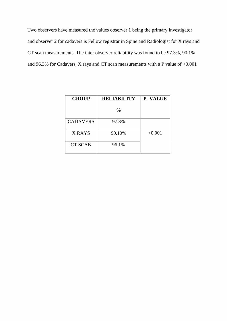
Two observers have measured the values observer 1 being the primary investigator
and observer 2 for cadavers is Fellow registrar in Spine and Radiologist for X rays and
CT scan measurements. The inter observer reliability was found to be 97.3%, 90.1%
and 96.3% for Cadavers, X rays and CT scan measurements with a P value of <0.001
GROUP RELIABILITY
%
P- VALUE
CADAVERS 97.3%
<0.001 X RAYS 90.10%
CT SCAN 96.1%

Cadavers:
Inter Pars Distance (Ipr):
Considering all the cadaveric specimens in both the observers, the average inter pars
distances gradually increased from D12 to L4 with a mean of 24.3, 25.2, 29.9, 30.9,
and 33.9 mm respectively. The range being 22.8-28.2; 24.0-30.0; 28.1-31.1; 29.9-
33.4; and 32.6-36.8 mm at D12; L1; L2; L3 and L4 respectively. There is a significant
increase of inter pars distance from L2 to L3 and L3 to L4 and the inter pars distance
at D12 and L1 almost remained close.
Inter Pedicular Distance (Ipd):
The averages inter pedicular distance showed steady increase as we moved from D12
to L4 with a mean of 21.3, 22.7, 23.7, 24.9, and 28.3 mm respectively. The range
being 19.8-22.9; 21.1-24.0; 22.7-24.6; 23.8-25.6; and 24.8-29.7mm at D12; L1; L2;
L3 and L4 respectively . The inter pedicular distance increased in a constant manner
of 1 to 1.5mm increments from D12 to L3 and there is significant increase of 3-4 mm
from L3 to L4.
Inter pars - Inter pedicular distance (Ipr-Ipd):
The mean difference of the inter pars and inter pedicular distance by both the
observers showed a gradual increase from D12 to L4 without significant difference at
each level. The mean of Ipr-Ipd are 4.0, 4.2, 5.9, 6.6, and 6.6 mm respectively.

Ipr-Ipd almost remained the same at D12 and L1 and L3 and L4 respectively and with
a difference of 1 to 1.5mm at L1-L2 and L2-L3.
Ipr-Ipd/2:
Considering pars and pedicle are symmetrical and equidistant, Ipsilateral distance
from the lateral border of the pars and the medial border of the pedicle is calculated by
dividing the difference of inter pars and inter pedicular distance by two (Ipr-Ipd/2).
The average distance from the lateral border of the pars to that of the medial border of
the pedicle on one side are 2.0, 2.1, 2.9, 3.3 and 3.3 mm respectively from D12 to L4
which is very minimal.

CADAVERS:
LEVEL INTER-PARS
DISTANCE (Ipr)
IN MM
INTER-PEDICULAR
DISTANCE (Ipd) IN
MM
Ipr-Ipd/2
IN MM
OBSERVER 1 MEAN MEAN MEAN
D12 25.6 21.3 2.1
L1 26.5 22.1 2.2
L2 29.5 23.4 3.1
L3 31.3 24.4 3.4
L4 34.3 27.2 3.5
OBSERVER 2
D12
25.5 21.7 1.9
L1 26.4 22.5 2.0
L2 29.8 24.1 2.8
L3 31.7 25.2 3.2
L4 34.1 27.9 3.1

X rays:
Inter pars Distance (Ipr):
Of all the 100 normal radiographs studied the mean of inter pars distance measured by
both the observers are 25.6; 26.7; 28.5; 30.7; 33.8 mm respectively at D12, L2, L2,
L3, L4 respectively showing a gradual increase from D12 to L4 with a minimum
increase at D12 and L1. The range being 20.8-29.6; 21.6-30.2; 23.9-32.1; 25.2-33.6;
30.0-36.4 mm at D12, L1, L2, L3, L4 respectively.
Inter Pedicular Distance (Ipd):
The average inter pedicular distance of both the observers is 21.9; 22.8; 24.1; 25.3 and
27.3 mm at D12, L1, L2, L3, L4 respectively. The range being 18.5-25.4; 19.5-26.8;
19.4-27.2; 21.4-29.2 and 22.4-31.1 mm at D12; L1; L2; L3 and L4 respectively. The
24.3 25.2
29.9 30.9 33.9
21.3 22.7 23.7 24.9 28.3
Mean Of Both The Observers-Cadavers

inter pedicular distance increased in a steady manner from D12 to L3 and there is
significant increase from L3 to L4.
Inter pars - Inter pedicular distance (Ipr-Ipd):
The mean difference of the inter pars and inter pedicular distance by both the
observers showed a gradual increase from D12 to L4 without significant difference at
each level. The mean of Ipr-Ipd are 3.7, 3.9, 4.4, 5.4, and 6.6 mm respectively.
Ipr-Ipd/2:
The average ipsilateral distance from the lateral border of the pars to that of the medial
border of the pedicle on one side are 1.8, 1.9, 2.2, 2.7 and 3.3 mm respectively from
D12 to L4.

X-RAYS:
LEVEL
INTER-PARS
DISTANCE (Ipr) IN
MM
INTER-PEDICULAR
DISTANCE (Ipd) IN
MM
Ipr-Ipd/2
IN MM
OBSERVER 1 MEAN MEAN MEAN
D12 25.5 21.8 1.9
L1 26.7 22.7 2.0
L2 28.6 24.1 2.2
L3 30.7 25.0 2.8
L4 34.1 27.0 3.5
OBSERVER 2
D12 25.6 22.0 1.8
L1 26.8 23.0 1.9
L2 28.5 24.2 2.2
L3 30.6 25.5 2.6
L4 33.6 27.5 3.1

CT Scans:
Inter pars Distance (Ipr):
Measurements were taken from 50 normal CT scans and the mean of inter pars
distance measured by both the observers are 22.6; 23.7; 24.5; 26.8; 30.3 mm
respectively at D12, L1, L2, L3, L4 respectively showing a gradual increase from D12
to L4. The range being 19.1-28.8; 19.1-29.2; 21.1-30.7; 21.8-33.8; 23.8-38.6mm at
D12, L1, L2, L3, L4 respectively.
Inter Pedicular Distance (Ipd):
The average inter pedicular distance of both the observers is 19.1; 19.7; 20.5; 21.4 and
22.6 mm at D12, L1, L2, L3, L4 respectively. The range being 16.6-22.0; 16.2-22.1;
17.9-23.2; 18.2-24.1 and 19.2-25.7 mm at D12; L1; L2; L3 and L4 respectively. The
inter pedicular distance increased in a steady manner from D12 to L4.
25.6 26.7 28.5 30.7
33.8
21.9 22.8 24.1 25.3 27.3
Mean Of Both The Observers-X Rays

Inter pars - Inter pedicular distance (Ipr-Ipd):
The mean difference of the inter pars and inter pedicular distance by both the
observers showed a gradual increase from D12 to L4 with a significant difference at
L3 to L4 level. The mean of Ipr-Ipd are 3.6, 3.5, 4.0, 5.4, and 7.7 mm respectively.
Ipr-Ipd/2:
The average ipsilateral distance from the lateral border of the pars to that of the medial
border of the pedicle on one side are 1.8, 1.8, 2.0, 2.7 and 3.8 mm respectively from
D12 to L4.

CT Scans:
LEVEL
INTER-PARS
DISTANCE (Ipr)
IN MM
INTER-
PEDICULAR
DISTANCE (Ipd)
IN MM
Ipr-Ipd/2
IN MM
OBSERVER 1 MEAN(SD) MEAN(SD) MEAN
D12 22.8 18.9 1.9
L1 22.9 19.3 1.8
L2 24.2 19.9 2.1
L3 26.6 20.9 2.8
L4 30.5 21.9 4.3
OBSERVER 2
D12 22.5 19.2 1.6
L1 23.5 20.0 1.7
L2 24.8 21.0 1.9
L3 26.9 21.8 2.5
L4 30.2 23.4 3.4

The Mean of Inter pars distance(Ipr), Inter Pedicular distance(Ipd), Inter pars-Inter
pedicular distance(Ipr-Ipd) and ipsilateral distance(Ipr-Ipd/2) at all levels (D12-L4)
across cadavers, X-rays and CT scan is shown in the table below.
Mean Of Ipr, Ipd, Ipr-Ipd, and Ipr-Ipd/2 Of Both The Observers In All Three
Groups:
D12 L1 L2 L3 L4
Ipr 24.2 25.0 27.6 29.5 32.7
Ipd 20.8 21.7 22.8 23.9 26.1
Ipr-Ipd 3.8 3.9 4.8 5.8 7.0
Ipr-Ipd/2 1.9 1.9 2.4 2.9 3.1
22.6 23.2 24.5 26.8
30.3
19.1 19.7 20.5 21.4 22.6
Mean Of Both The Observers In CT

GRAPH SHOWING MEAN OF ALL MEASUREMENTS OF BOTH OBSERVERS:
In the present study we aimed at studying the relationship between the lateral border
of the pars to that of the medial border the pedicle. Ipr-Ipd/2 gives the ipsilateral
distance measured on one side assuming pars and pedicle are symmetrical on both
sides. The Ipr-Ipd/2 is compared among the three groups and shown in the following
table.
D12 L1 L2 L3 L4
Ipr 24.2 25 27.6 29.5 32.7
Ipd 20.8 21.7 22.8 23.9 26.1
Ipr-Ipd 3.8 3.9 4.8 5.8 7
Ipr-Ipd/2 1.9 1.9 2.4 2.9 3.1
0
5
10
15
20
25
30
35
in m
m

Comparison Of Mean Ipr-Ipd/2 By Both The Observers In All Groups:
GROUP D12 L1 L2 L3 L4
CADAVERS 2 2.1 2.9 3.3 3.3
X RAYS 1.8 1.9 2.2 2.7 3.3
CT 1.8 1.8 2 2.7 3.8
2 2.1
2.9
3.3 3.3
1.8 1.9 2.2
2.7
3.3
1.8 1.8 2
2.7
3.8
D12 L1 L2 L3 L4
Ipr-Ipd/2 IN ALL GROUPS
CADAVERS X RAYS CT
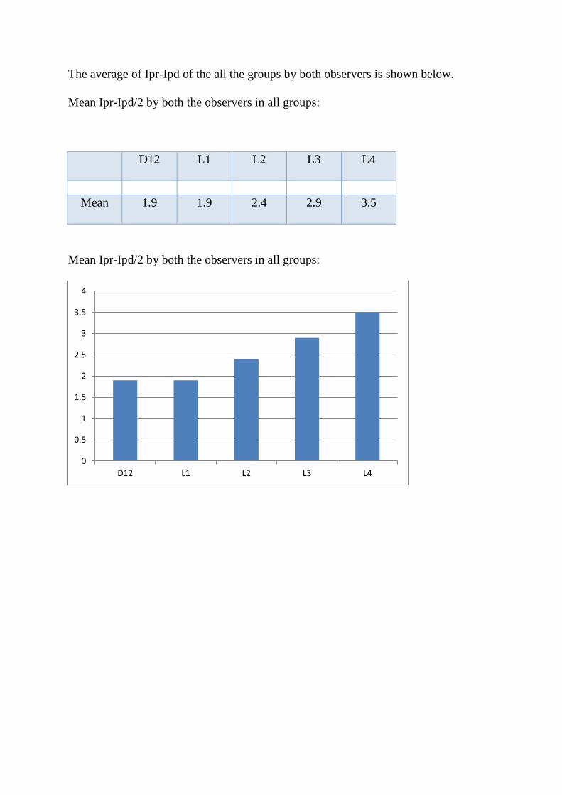
The average of Ipr-Ipd of the all the groups by both observers is shown below.
Mean Ipr-Ipd/2 by both the observers in all groups:
D12 L1 L2 L3 L4
Mean 1.9 1.9 2.4 2.9 3.5
Mean Ipr-Ipd/2 by both the observers in all groups:
0
0.5
1
1.5
2
2.5
3
3.5
4
D12 L1 L2 L3 L4

DISCUSSION:
Pars interarticularis playing a key role in adding structural support to the spinal
column yet there is not much literature available on its anatomic feature and its
relationship to the surrounding spinal canal structures.
There were significant studies describing the morphometry of the posterior elements
of the vertebral body and their relation to the neural structures. There were equal
number of morphometric analysis of the posterior elements and their relationship in
guiding the entry point for the pedicle screw placement. The relationship of the bony
anatomical landmarks namely transverse process, superior facet joint, pars
interarticularis were studied in detail by various authors to define ideal anatomical
land mark for guiding the entry point for the pedicle screw insertion.
Free hand technique for placing the pedicle screw has gained its importance and is
more used compared with assisted navigation methods there by decreasing the
radiation hazard and saving the operating time. With the studies showing increased
accuracy and ease of placing the pedicle screw with safety along with minimal risks
involved in placing the screw given that the operating surgeon was aware of the
importance of the anatomical landmarks and adequate training. With all the added
advantages like providing three dimensional stability, increased fusion rates, not
needing intact posterior elements pedicle screw gained its importance and has been
the preferred method for pedicle screw insertion.
Among the land marks that guide the pedicle screw placement pars being made up of
dense cortical bone and not easily deformed in degenerative conditions, there were

few studies that were done on the relationship between the pars interarticualris and the
pedicle. There were studies documented on the inter pars distance at lumbar level by
Austin peters et al(53) analyzed 265 vertebra and demonstrated that there is gradual
increase in the inter pars size from L1 to L4 and the inter pars distance increased
dramatically from L4 to L5 and also found that the trend was similar in both males
and females.
Austin Peters et al
LEVEL
INTER PARS
DISTANCE
L1 24MM
L2 25MM
L3 27MM
L4 32MM
L5 41MM
In one study by E. Yee et al(52) in their cadaveric study measured the average width
of the pars remained from L1 to L5 vertebra from the medial edge of the pedicle on
the ipsilateral side following a serial laminectomy from midline to the medial border
of the pedicle. The values are shown below

E. Yee et al:
LEVEL
REMNANT
PARS RANGE
L1 4mm 3-6mm
L2 6mm 5-7mm
L3 8mm 4-9mm
L4 11mm 9-14mm
L5 16mm 13-17mm
In separate studies Inter pedicular distance was documented by various studies in an
attempt to study the dimensions of the spinal canal.
Tarek Aly et al(56) measured the Interpedicular distance along with other parameters
in 300 normal Egyptian population using CT scan from L1 to S1and demonstrated that
the inter pedicular distance showed a steady increase from L1 to L5
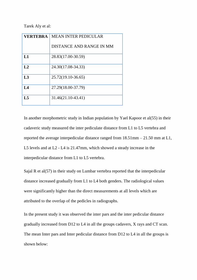
Tarek Aly et al:
VERTEBRA MEAN INTER PEDICULAR
DISTANCE AND RANGE IN MM
L1 28.83(17.00-30.59)
L2 24.30(17.08-34.33)
L3 25.72(19.10-36.65)
L4 27.29(18.00-37.79)
L5 31.46(21.10-43.41)
In another morphometric study in Indian population by Yael Kapoor et al(55) in their
cadaveric study measured the inter pediculate distance from L1 to L5 vertebra and
reported the average interpedicular distance ranged from 18.51mm – 21.50 mm at L1,
L5 levels and at L2 - L4 is 21.47mm, which showed a steady increase in the
interpedicular distance from L1 to L5 vertebra.
Sajal R et al(57) in their study on Lumbar vertebra reported that the interpedicular
distance increased gradually from L1 to L4 both genders. The radiological values
were significantly higher than the direct measurements at all levels which are
attributed to the overlap of the pedicles in radiographs.
In the present study it was observed the inter pars and the inter pedicular distance
gradually increased from D12 to L4 in all the groups cadavers, X rays and CT scan.
The mean Inter pars and Inter pedicular distance from D12 to L4 in all the groups is
shown below:

Mean of Inter Pars and Inter Pedicular distance in all groups from D12 to L4 in
MM.
D12 L1 L2 L3 L4
Ipr 24.2 25.0 27.6 29.5 32.7
Ipd 20.8 21.7 22.8 23.9 26.1
Mean Of Ipr, Ipd, Ipr-Ipd, and Ipr-Ipd/2 Of Both The Observers In All Three
Groups in MM:
Ipr Ipd Ipr-Ipd Ipr-Ipd/2
D12 24.2 20.8 3.8 1.9
L1 25 21.7 3.9 1.9
L2 27.6 22.8 4.8 2.4
L3 29.5 23.9 5.8 2.9
L4 32.7 26.1 7 3.1

We went ahead further in deriving the distance from the lateral border of the pars inter
articularis to that of the medial border of the pedicle. Assuming that pars inter
articualris and pedicle on right and left side are symmetrical in their anatomy and
equidistantly placed, the Inter pars distance minus Inter pedicular distance when
divided into half (Ipr-Ipd/2) gives distance on one side i.e., distance between the
lateral border of the pars inter articularis to that of the medial border of the pedicle.
Comparison of Ipr-Ipd/2 in all the groups in MM:
D12 L1 L2 L3 L4
CADAVERS 2 2.1 2.9 3.3 3.3
X RAYS 1.8 1.9 2.2 2.7 3.3
CT 1.8 1.8 2 2.7 3.8
Mean Ipr-Ipd/2 by both the observers in all groups in MM:
D12 L1 L2 L3 L4
Mean 1.9 1.9 2.4 2.9 3.5

So the mean distance from the lateral border of the pars to that of the medial border of
the pedicle in the cadavers almost remained constant except for a few mm variations.
Vaccaro et al(40) in 2008 in their Anatomical study described the relationship
between pedicle center to the Mid-Lateral pars in lower Lumbar vertebra L3 to S1, as
a guide to pedicle screw placement and concluded that mid lateral pars is a reliable
anatomic reference. They reported that in medial-lateral direction, the pedicle centre is
2.9 mm lateral to the MLP at L3 and L4 respectively and L5, it is 1.5 and 4.5 mm
lateral to the MLP for a type I and type II L5 pedicle, respectively. The percent of
pedicle lateral to the MLP is 77% and 71% at L3 and L4. At L5, it is 58% and 70% for
type I and type II pedicle respectively.
Form the present study it was found that the lateral border of the pars interarticularis
lies in close relationship with that of the medial border of the pedicle from D12 to L4.
This relationship helps in choosing the medio-lateral entry point with pars as a
reference anatomical landmark.
The clinical implications being- pars inter articularis is routinely seen in all the
posterior exposures and easy to identify due to its dense cortical nature and rarely get
altered due to the degenerative changes unlike facet joints. As long as one stays on to
the lateral border of the pars or few mm lateral to the lateral border of the pars inter
articularis in medio lateral direction the chances of breaching the medial border of the
pedicle can be minimized.

By the this study we found a new relationship between the lateral border of the pars
interarticularis to that of the medial border of the pedicle from D12 to L4 and there by
describing a new method in defining a the entry point in medio-lateral direction using
lateral border of the pars interarticularis as consistent anatomical land mark.


CONCLUSIONS
Inter pars distance and Inter Pedicular distance showed a steady increase from D12 to
L4 vertebra.
The lateral border of the pars inter articularis lies in close relationship to the medial
border of the pedicle from D12 to L4 vertebra.
The lateral border of the pars interarticularis can be used as a consistent anatomical
land mark in defining the entry point in medio-lateral direction for the pedicle screw
insertion in lumbar spine.
LIMITATIONS:
Measurements were not taken in same subjects in all the groups.
Magnification in the radiological part was not accounted for
In spite of every effort taken in order to minimize the errors while taking the
measurements there are still chances of errors to have occurred
Though we have collected Radiographs and CT scans of normal subjects from our
data base there are chances of altered anatomy due to subtle degenerative changes.
Further Directions:
As we are dealing with the measurements in millimeters one can focus on establishing
concrete methodology by studying same ethnic group and documenting both the
anatomical radiological parameters.
Further study should focus on clinical application of using lateral border of the pars as
consistent anatomical land mark and evaluating its accuracy compared with other
methods.

BIBLOGRAPHY
1. Krenz J, Troup JD. The structure of the pars interarticularis of the lower lumbar
vertebrae and its relation to the etiology of spondylolysis, with a report of a
healing fracture in the neural arch of a fourth lumbar vertebra. J Bone Joint Surg
Br. 1973 Nov;55(4):735–41.
2. Ranu HS. Three dimensional surgical simulations of the spine. J Biomed Eng.
1982 Oct;4(4):285–8.
3. Cyron BM, Hutton WC. The fatigue strength of the lumbar neural arch in
spondylolysis. J Bone Joint Surg Br. 1978 May;60–B(2):234–8.
4. Ivanov AA, Faizan A, Ebraheim NA, Yeasting R, Goel VK. The effect of
removing the lateral part of the pars interarticularis on stress distribution at the
neural arch in lumbar foraminal microdecompression at L3-L4 and L4-L5:
anatomic and finite element investigations. Spine. 2007 Oct 15;32(22):2462–6.
5. Sairyo K, Katoh S, Sasa T, Yasui N, Goel VK, Vadapalli S, et al. Athletes with
unilateral spondylolysis are at risk of stress fracture at the contralateral pedicle and
pars interarticularis: a clinical and biomechanical study. Am J Sports Med. 2005
Apr;33(4):583–90.
6. Harrington PR, Tullos HS. Reduction of severe spondylolisthesis in children.
South Med J. 1969 Jan;62(1):1–7.

7. Shands ARJ, Barr JS, Colonna PC, Noall L. END-RESULT STUDY OF THE
TREATMENT OF IDIOPATHIC SCOLIOSIS: Report of the Research
Committee of The American Orthopaedic Association. JBJS. 1941 Oct;23(4):963.
8. Dickson JH, Erwin WD, Rossi D. Harrington instrumentation and arthrodesis for
idiopathic scoliosis. A twenty-one-year follow-up. J Bone Joint Surg Am. 1990
Jun;72(5):678–83.
9. Luque ER. Interpeduncular Segmental Fixation. Clin Orthop. 1986 Feb;203:54.
10. King D. Internal fixation for lumbosacral fusion. J Bone Joint Surg Am. 1948
Jul;30A(3):560–5.
11. Boucher HH. A method of spinal fusion. J Bone Joint Surg Br. 1959 May;41–
B(2):248–59.
12. Roy-Camille R, Saillant G, Mazel C. Internal fixation of the lumbar spine with
pedicle screw plating. Clin Orthop. 1986 Feb;(203):7–17.
13. Steffee AD, Biscup RS, Sitkowski DJ. Segmental spine plates with pedicle
screw fixation. A new internal fixation device for disorders of the lumbar and
thoracolumbar spine. Clin Orthop. 1986 Feb;(203):45–53.
14. Gaines RWJ. The Use of Pedicle-Screw Internal Fixation for the Operative
Treatment of Spinal Disorders*. JBJS. 2000 Oct;82(10):1458.

15. Gaines RW, Carson WL, Satterlee CC, Groh GI. Improving quality of spinal
internal fixation: evolution toward" ideal immobilization": a biomechanical study.
Orthop Trans. 1987;11(1):86.
16. Chang KW, Dewei Z, McAfee PC, Warden KE, Farey ID, Gurr KR. A
comparative biomechanical study of spinal fixation using the combination spinal
rod-plate and transpedicular screw fixation system. J Spinal Disord.
1988;1(4):257–66.
17. Parker JW, Lane JR, Karaikovic EE, Gaines RW. Successful Short-Segment
Instrumentation and Fusion for Thoracolumbar Spine Fractures: A Consecutive
4½-Year Series. Spine. 2000 May 1;25(9):1157–1170.
18. McCormack T, Karaikovic E, Gaines RW. The load sharing classification of
spine fractures. Spine. 1994 Aug 1;19(15):1741–4.
19. Roy-Camille R, Saillant G, Mazel C. Plating of thoracic, thoracolumbar, and
lumbar injuries with pedicle screw plates. Orthop Clin North Am. 1986
Jan;17(1):147–59.
20. Castro WH, Halm H, Jerosch J, Malms J, Steinbeck J, Blasius S. Accuracy of
pedicle screw placement in lumbar vertebrae. Spine. 1996 Jun 1;21(11):1320–4.
21. Zeiller SC, Lee J, Lim M, Vaccaro AR. Posterior thoracic segmental pedicle
screw instrumentation: evolving methods of safe and effective placement. Neurol
India. 2005 Dec;53(4):458–65.

22. Mattei T, Meneses M, Milano J, Ramina R. “Free-hand” technique for
thoracolumbar pedicle screw instrumentation: Critical appraisal of current “State-
of-Art.” Neurol India. 2009;57(6):715.
23. Weinstein JN, Spratt KF, Spengler D, Brick C, Reid S. Spinal pedicle fixation:
reliability and validity of roentgenogram-based assessment and surgical factors on
successful screw placement. Spine. 1988 Sep;13(9):1012–8.
24. Bransford R, Bellabarba C, Thompson JH, Henley MB, Mirza SK, Chapman
JR. The safety of fluoroscopically-assisted thoracic pedicle screw instrumentation
for spine trauma. J Trauma. 2006 May;60(5):1047–52.
25. Kuntz C, Maher PC, Levine NB, Kurokawa R. Prospective evaluation of
thoracic pedicle screw placement using fluoroscopic imaging. J Spinal Disord
Tech. 2004 Jun;17(3):206–14.
26. Carl AL, Khanuja HS, Gatto CA, Matsumoto M, vomLehn J, Schenck J, et al.
In vivo pedicle screw placement: image-guided virtual vision. J Spinal Disord.
2000 Jun;13(3):225–9.
27. Rampersaud YR, Pik JHT, Salonen D, Farooq S. Clinical accuracy of
fluoroscopic computer-assisted pedicle screw fixation: a CT analysis. Spine. 2005
Apr 1;30(7):E183-190.
28. Rose RD, Welch WC, Balzer JR, Jacobs GB. Persistently electrified pedicle
stimulation instruments in spinal instrumentation. Technique and protocol
development. Spine. 1997 Feb 1;22(3):334–43.
29. Welch WC, Rose RD, Balzer JR, Jacobs GB. Evaluation with evoked and
spontaneous electromyography during lumbar instrumentation: a prospective
study. J Neurosurg. 1997 Sep;87(3):397–402.
30. Berry JL, Moran JM, Berg WS, Steffee AD. A morphometric study of human
lumbar and selected thoracic vertebrae. Spine. 1987 May;12(4):362–7.
31. McCormack BM, Benzel EC, Adams MS, Baldwin NG, Rupp FW, Maher DJ.
Anatomy of the thoracic pedicle. Neurosurgery. 1995 Aug;37(2):303–8.
32. Panjabi MM, Goel V, Oxland T, Takata K, Duranceau J, Krag M, et al. Human
lumbar vertebrae. Quantitative three-dimensional anatomy. Spine. 1992
Mar;17(3):299–306.
33. Hyun S-J, Kim YJ, Cheh G, Yoon SH, Rhim S-C. Free Hand Pedicle Screw
Placement in the Thoracic Spine without Any Radiographic Guidance : Technical
Note, a Cadaveric Study. J Korean Neurosurg Soc. 2012 Jan;51(1):66–70.
34. Gertzbein SD, Robbins SE. Accuracy of pedicular screw placement in vivo.
Spine. 1990 Jan;15(1):11–4.
35. Weinstein JN, Rydevik BL, Rauschning W. Anatomic and technical
considerations of pedicle screw fixation. Clin Orthop. 1992 Nov;(284):34–46.
36. Kim YJ, Lenke LG, Bridwell KH, Cho YS, Riew KD. Free hand pedicle screw
placement in the thoracic spine: is it safe? Spine. 2004 Feb 1;29(3):333–342;
discussion 342.

37. Karapinar L, Erel N, Ozturk H, Altay T, Kaya A. Pedicle screw placement with
a free hand technique in thoracolumbar spine: is it safe? J Spinal Disord Tech.
2008 Feb;21(1):63–7.
38. Silbermann J, Riese F, Allam Y, Reichert T, Koeppert H, Gutberlet M.
Computer tomography assessment of pedicle screw placement in lumbar and
sacral spine: comparison between free-hand and O-arm based navigation
techniques. Eur Spine J Off Publ Eur Spine Soc Eur Spinal Deform Soc Eur Sect
Cerv Spine Res Soc. 2011 Jun;20(6):875–81.
39. Magerl FP. Stabilization of the lower thoracic and lumbar spine with external
skeletal fixation. Clin Orthop. 1984 Oct;(189):125–41.
40. Su BW, Kim PD, Cha TD, Lee J, April EW, Weidenbaum M, et al. An
anatomical study of the mid-lateral pars relative to the pedicle footprint in the
lower lumbar spine. Spine. 2009;34(13):1355–1362.
41. Parker SL, McGirt MJ, Farber SH, Amin AG, Rick A-M, Suk I, et al. Accuracy
of Free-Hand Pedicle Screws in the Thoracic and Lumbar Spine: Analysis of 6816
Consecutive Screws. Neurosurgery. 2011 Jan;68(1):170–8.
42. Hou S, Hu R, Shi Y. Pedicle morphology of the lower thoracic and lumbar
spine in a Chinese population. Spine. 1993 Oct 1;18(13):1850–5.
43. Ebraheim NA, Rollins JRJ, Xu R, Yesting RA. Projection of the Lumbar
Pedicle and its Morphometric Analysis. Spine. 1996 Jun 1;21(11):1296–1300.

44. Vaccaro AR, Rizzolo SJ, Balderston RA, Allardyce TJ, Garfin SR, Dolinskas
C, et al. Placement of pedicle screws in the thoracic spine. Part II: An anatomical
and radiographic assessment. J Bone Joint Surg Am. 1995 Aug;77(8):1200–6.
45. Vaccaro AR, Rizzolo SJ, Allardyce TJ, Ramsey M, Salvo J, Balderston RA, et
al. Placement of pedicle screws in the thoracic spine. Part I: Morphometric
analysis of the thoracic vertebrae. J Bone Joint Surg Am. 1995 Aug;77(8):1193–9.
46. Avila MJ, Baaj AA. Freehand Thoracic Pedicle Screw Placement: Review of
Existing Strategies and a Step-by-Step Guide Using Uniform Landmarks for All
Levels. Cureus [Internet]. [cited 2017 Oct 22];8(2). Available from:
https://www.ncbi.nlm.nih.gov/pmc/articles/PMC4803536/
47. Elliott MJ, Slakey CJB. Thoracic Pedicle Screw Placement: Analysis Using
Anatomical Landmarks Without Image Guidance. J Pediatr Orthop. 2007
Aug;27(5):582–586.
48. Tian N-F, Xu H-Z. Image-guided pedicle screw insertion accuracy: a meta-
analysis. Int Orthop. 2009 Aug;33(4):895–903.
49. Puvanesarajah V, Liauw JA, Lo S, Lina IA, Witham TF. Techniques and
accuracy of thoracolumbar pedicle screw placement. World J Orthop. 2014 Apr
18;5(2):112–23.
50. Weiner BK, Walker M, Wiley W, McCulloch JA. The lateral buttress: an
anatomic feature of the lumbar pars interarticularis. Spine. 2002;27(17):E385–
E387.

51. McCulloch JA, Weiner BK. Microsurgery in the lumbar intertransverse
interval. Instr Course Lect. 2002;51:233–41.
52. Yee E, Langton D, Chan C. Lumbar Pars Distance from the Medial Edge of the
Pedicle. Orthop Proc. 2010 Mar 1;92–B(SUPP I):218–218.
53. Peters A, Hoelscher C, Edusei E, Skalli W, Errico T. Interpars - an anatomical
examination of the lumbar pars interarticulares with significance for spinal
decompression. Bull Hosp Jt Dis 2013. 2014;72(3):225–30.
54. El-Rakhawy M. Lumbar vertebral canal stenosis: concept of morphometric and
radiometric study of the human lumbar vertebral canal. Anat Int J Exp Clin Anat.
2010;4:51–62.
55. Yael Kapoor*, Anil. R. Sherke, Krishnaiah.M, Suseelamma. D. SJAMS-
23C104Morphometry of the Lumbar Vertebrae and its Clinical Significance.
56. Aly T, Amin O. Geometrical dimensions and morphological study of the
lumbar spinal canal in the normal Egyptian population. Orthopedics. 2013
Feb;36(2):e229-234.
57. Mitra SR, Datir SP, Jadhav SO. Morphometric study of the lumbar pedicle in
the Indian population as related to pedicular screw fixation. Spine. 2002 Mar
1;27(5):453–9.
58. Fujiwara A, Tamai K, Yamato M, An HS, Yoshida H, Saotome K, et al. The
relationship between facet joint osteoarthritis and disc degeneration of the lumbar

spine: an MRI study. Eur Spine J Off Publ Eur Spine Soc Eur Spinal Deform Soc
Eur Sect Cerv Spine Res Soc. 1999;8(5):396–401.
59. Tischer T, Aktas T, Milz S, Putz RV. Detailed pathological changes of human
lumbar facet joints L1–L5 in elderly individuals. Eur Spine J. 2006
Mar;15(3):308–15.
60. Robertson PA, Novotny JE, Grobler LJ, Agbai JU. Reliability of axial
landmarks for pedicle screw placement in the lower lumbar spine. Spine. 1998 Jan
1;23(1):60–6.

ANNEXURES
SCANNED COPY OF IRB LETTER

THESIS DATA