the anti-lotus leaf effect in nanohydrodynamic bump arrays
TRANSCRIPT

The anti-lotus leaf effect in nanohydrodynamic bump arrays
This article has been downloaded from IOPscience. Please scroll down to see the full text article.
2010 New J. Phys. 12 085008
(http://iopscience.iop.org/1367-2630/12/8/085008)
Download details:
IP Address: 128.112.48.116
The article was downloaded on 16/02/2011 at 15:16
Please note that terms and conditions apply.
View the table of contents for this issue, or go to the journal homepage for more
Home Search Collections Journals About Contact us My IOPscience

T h e o p e n – a c c e s s j o u r n a l f o r p h y s i c s
New Journal of Physics
The anti-lotus leaf effect in nanohydrodynamicbump arrays
Keith Morton1, Ophelia K C Tsui2, Chih-Kuan Tung3,James C Sturm4, Stephen Y Chou4 and Robert Austin5,6,7
1 National Research Council, Montreal, QC, Canada2 Department of Physics, Boston University, Boston, MA, USA3 Department of Physics, Hong Kong University of Science and Technology,Kowloon, Hong Kong4 Department of Electrical Engineering, Princeton University, Princeton,NJ, USA5 Department of Physics, Princeton University, Princeton, NJ, USA6 Visiting Member, Institute for Advanced Study, Hong Kong Universityof Science and Technology, Kowloon, Hong KongE-mail: [email protected]
New Journal of Physics 12 (2010) 085008 (14pp)Received 1 September 2009Published 19 August 2010Online at http://www.njp.org/doi:10.1088/1367-2630/12/8/085008
Abstract. In this paper, we address the hydraulic flow of fluids on andwithin nanofabricated hydrophilic (as opposed to hydrophobic) surfaces, andthe influence of an extended precursor film on the wetting dynamics of waterpenetrating a nano-textured array of posts that has no sealing surface (open-top).The width of the precursor film in front of the wetting edge δ is extraordinarilylarge, approximately 2 mm for our device, and it drives the wetting penetrationfilm in the open-top array. We discuss the way this thin precursor film controlsthe movement of the macroscopic wetting front Lw and its dynamics in thenanofabricated array of posts. Rapid and controllable transport of nanoparticlesin such an open top array of posts, as controlled by the precursor film, isdemonstrated using a bump array textured morphology.
7 Author to whom any correspondence should be addressed.
New Journal of Physics 12 (2010) 0850081367-2630/10/085008+14$30.00 © IOP Publishing Ltd and Deutsche Physikalische Gesellschaft
2
Contents
1. Introduction 22. Basic theory 23. Methods and materials 74. Results 95. Conclusions 13Acknowledgments 13References 14
1. Introduction
The present paper explores the effect of nanofabricated surfaces on the wetting dynamics offluids on hydrophilic surfaces, and how nanoflow caused by wetting dynamics can effectivelytransport objects in nanoarrays. The nanoarray we use here is a highly ordered array consistingof a rotated square lattice of posts; the rotation of the array relative to the average flow directiongives rise to the unusual transport properties of colloidal particles in the array [1]. Unfortunately,in such a short paper as this we can do justice to neither the complexity of the dynamics ofcolloidal particles in a rotated nanoarray (a nanobump array) nor the complexity of how water,a volatile and highly polar fluid, wets such an array. We hope we can point out some fascinatingaspects of the dynamics of these two problems.
The emphasis of this paper is really on the transport of objects in an open-top nanobumparray, not the wetting physics per se. However, there is a problem with nanobump arrays thatforces us to consider the wetting dynamics. The problem is that as the dimensions of arrays usedfor sorting particles shrink to the nanoscale, the hydrodynamic impedance of the device, definedas the pressure/length gradient needed for a given flux of fluid flow, becomes prohibitivelyhigh. One potential way around this problem is to run the device ‘open-top’, that is, withouta top sealing the device, and let evaporative transport generate the flux drive. Opening thetop decreases the shear gradients, and use of evaporation removes the need for high-pressureexternal pumps, in principle. This experimental paper shows that this scheme has the potentialto work.
Ordinarily, we would show the results first and then present the theory to explain the results.However, we felt in this paper that it would perhaps be best to first outline the theory and thenshow how the theory might begin to explain the results. Unfortunately, we are dealing withan extremely complex system: out of equilibrium flow of a volatile liquid in a nanostructuredopen-top device where significant evaporation is occurring. We can only sketch out a few linesof analysis that illuminate basic, hopefully relevant, aspects of the complexity of the problem.The good news is that, despite the complexity, in fact it is possible to have high rates of flow insuch an open-top nanostructured nanobump array and achieve high-resolution fractionation inthe open-top evaporative drive configuration.
2. Basic theory
There has been a great deal of discussion recently about the influence of nanostructuring ofhydrophobic surfaces on the decrease of the wetting properties of water to the point of total
New Journal of Physics 12 (2010) 085008 (http://www.njp.org/)

3
exclusion of the liquid from the surface. This total exclusion of water by a nano-texturedhydrophobic surface is called the lotus-leaf effect, in analogy to the remarkable non-wetting andself-cleaning properties of the lotus leaf [2]. Hydrophilic nanostructured surfaces, as opposedto hydrophobic nanostructured surfaces, are perhaps more interesting dynamically because theydo wet the surface. In particular, as we stated in the introduction, we are interested in decreasingthe hydrodynamic resistance using nanostructures, and exploiting evaporation of volatile fluidsto drive flow functionally through nanostructured surfaces.
The shear gradients are driven by boundary conditions and drive the pressure gradients.One of the fundamental assumptions in macroscopic hydrodynamics is the presence of a stick-boundary surface where fluid voxels are at rest with respect to the surface [3]. The argumentfor the apparent necessity of a stick-boundary surface is very simple. In a fluid of viscosity η,the local shearing stress σxz = Fx/Axy in the Ex-direction is proportional to the local transverseshear in the Ez-direction normal to the surface:
σxz =Fx
Axy= η
∂vx
∂z. (1)
Hence, if the local stress is to be finite the gradients in velocity must be finite and there cannotbe fluid at the wall surface moving with a finite velocity parallel to the wall, giving rise to aninfinite shear. The perceived necessity for fluid voxels in contact with the wall to be at restrelative to the wall gives rise to stick boundary conditions, which circumvents the divergenceproblem for slip at the boundary.
It is less well known that equation (1) is not the only possible boundary condition thatsatisfies the Navier–Stokes equation [4, 5]. In freshman physics, we routinely handle frictionalforces by assuming that a solid moves with finite slip speed vs relative to another surface givingrise to a drag force proportional to a coefficient of friction κ . A similar model might applyfor fluids moving near a wall. We assume a linear relation between the drag force and the slipvelocity of the surface moving through the fluid:
σxz = κvs, (2)
where κ is the drag coefficient. We then can assume that at the wall (z = 0):
vs =η
κ
∂vx
∂z= b
∂vx
∂z, (3)
where b is defined as the slip length. In this model, there is finite slip at the surface. It hasbeen proposed [6] that this slip-boundary condition can profoundly change the hydrodynamicimpedance of nanopatterned surfaces.
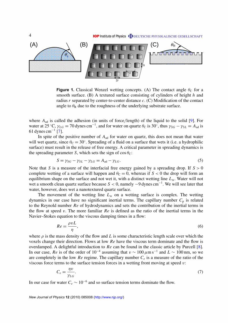
A related issue to the possible failure of stick-boundary conditions is the dynamics ofwetting of surfaces by liquids, and the effect of nanopatterning of a surface on the wettingprofile. In the case of a smooth surface, a liquid drop that partially wets a solid surface willform a contact angle θC between the surface of the liquid and the solid surface. See figure 1 forthe definition of the contact angle θC. The surface wetting phenomenon involves three states ofmatter and their interaction, as expressed by surface tensions between the states: the gas phaseG of the wetting fluid, the liquid phase L of the wetting fluid and the solid state that is beingwet S. If γGL denotes the surface tension between the gas and the liquid, γSG the surface tensionbetween the solid and the gas and γSL the surface tension between the solid and the liquid, thenthe Young relation [11] gives
γSG − γSL = γLG cos θC = Aad, (4)
New Journal of Physics 12 (2010) 085008 (http://www.njp.org/)
4
θc
h
2r
(A) (B)
c
θR(C)
Figure 1. Classical Wenzel wetting concepts. (A) The contact angle θC for asmooth surface. (B) A textured surface consisting of cylinders of height h andradius r separated by center-to-center distance c. (C) Modification of the contactangle to θR due to the roughness of the underlying substrate surface.
where Aad is called the adhesion (in units of force/length) of the liquid to the solid [9]. Forwater at 25 ◦C, γLG = 70 dynes cm−1, and for water on quartz θC is 30◦, thus γSG − γSL = Aad is61 dynes cm−1 [7].
In spite of the positive number of Aad for water on quartz, this does not mean that waterwill wet quartz, since θC = 30◦. Spreading of a fluid on a surface that wets it (i.e. a hydrophilicsurface) must result in the release of free energy. A critical parameter in spreading dynamics isthe spreading parameter S, which sets the sign of cos θC:
S = γSG − γSL − γLG = Aad − γLG . (5)
Note that S is a measure of the interfacial free energy gained by a spreading drop. If S > 0complete wetting of a surface will happen and θC = 0, whereas if S < 0 the drop will form anequilibrium shape on the surface and not wet it, with a distinct wetting line Lw. Water will notwet a smooth clean quartz surface because S < 0, namely −9 dynes cm−1. We will see later thatwater, however, does wet a nanotextured quartz surface.
The movement of the wetting line Lw on a wetting surface is complex. The wettingdynamics in our case have no significant inertial terms. The capillary number Cp is relatedto the Reynold number Re of hydrodynamics and sets the contribution of the inertial terms inthe flow at speed v. The more familiar Re is defined as the ratio of the inertial terms in theNavier–Stokes equation to the viscous damping times in a flow:
Re =ρvL
η, (6)
where ρ is the mass density of the flow and L is some characteristic length scale over which thevoxels change their direction. Flows at low Re have the viscous term dominate and the flow isoverdamped. A delightful introduction to Re can be found in the classic article by Purcell [8].In our case, Re is of the order of 10−4 assuming that v ∼ 100 µm s−1 and L ∼ 100 nm, so weare completely in the low Re regime. The capillary number Ce is a measure of the ratio of theviscous force terms to the surface tension forces in a wetting front moving at speed v:
Ce =ηv
γLG. (7)
In our case for water Ce ∼ 10−6 and so surface tension terms dominate the flow.
New Journal of Physics 12 (2010) 085008 (http://www.njp.org/)

5
Further, the prediction is that the spreading rate (the speed v at which the wetting line Lw
moves across the surface) of a drop for S > 0 should scale with S: a larger S should result ina fast speed v of the macroscopic wetting front, v = dLw/dt . In this view, the wetting line Lw
moves as a distinct line over a dry surface, wetting it. For volatile liquids such as water, theliquid evaporating from the drop can condense as a thin film in front of the drop interface andthe drop will wet by moving over a thin film of condensed phase called the precursor film, hencelocking S at zero and removing any S dependence on the wetting rate.
However, the precursor film can also occur for both volatile and non-volatile fluids [12],as deGennes has discussed [9]. In fact, there is a hydrodynamic reason why there must be aprecursor film in a wetting process: the viscous dissipation due to shear in a film of thickness xscales as 1/x and so a contact line moving across a dry surface will have a diverging shear forcewithout the existence of a precursor film, which acts as a slip boundary layer [9]. One can viewthis as another way to obtain slip boundary conditions, by movement of the macroscopic wettingfront Lw over the thin precursor film. Furthermore, since, as deGennes pointed out, virtually allof the viscous dissipation in the fluid occurs where the shear is highest, we can guess that it isthe dissipation in the precursor film that drives the primary wetting dynamics.
Roughening or texturing the surface changes both the statics and dynamics of wetting.If the surface is not smooth but textured, the Young relation given by equation (4) does notapply. The contact angles θC for a textured but chemically homogeneous surface can be greatlydifferent from that predicted by equation (4). Wetting of a textured surface can be quite acomplicated process, but there is an empirical relation called Wenzel’s equation, which canbe used to estimate the actual contact angle for a rough surface θR, given the smooth surfacecontact angle θC [13]:
cos θR = R cos θC, (8)
where R is the surface roughness ratio of the total surface area of the rough surface AR tothe smooth surface As and is thus always >1. Since a neutral surface has θC = π/2 and hencecos θC = 0, the effect of roughness is to decrease the angle for a hydrophilic surface (θC < π/2)and increase the angle for a hydrophobic surface (θC > π/2). Complete wetting will occur forsurfaces with roughness such that cos θR > +1 and complete repulsion occurs if the surface hascos θR < −1. We are concerned with the super-hydrophilic surfaces in this paper, which we callthe anti-lotus leaf effect.
Although we have an unusual pattern for the posts, a bump array [1], basically our texturedsurface has an increased area 1A due to the sides of the posts. If the center-to-center post–postspacing is c and the posts are of radius r and height h, the roughness R of our surface is
R ∼ 1 +2πrh
c2. (9)
Figure 1 shows the definition of the various parameters used in these equations.It was previously shown by McHale et al [14] that the simple Wenzel relationship
equation (8) could be used to model the static macroscopic wetting of a liquid in an arrayof posts made of a hydrophilic material and the evaluation of the macroscopic contact angle.Ishino and Okumura [15] have shown that the effect of texturing the surface does more thansimply change the contact angle as described by equation (8). If the material is hydrophilic, theprecursor film forms a thin penetration film that enters into the structured surface in advance ofthe wetting edge Lp and has an edge Lp, with width δ. In the words of Ishino and Okumura,the drop looks like a sunny-side-up egg sitting on the surface, with the yolk as the center of
New Journal of Physics 12 (2010) 085008 (http://www.njp.org/)

6
the drop and the precursor film as the thin egg white surrounding the yolk. This precursorfilm with edge line Lp does not have a constant thickness, but roughly the average thicknessh is [9]
h ∼ a ×
√3γLG
2S, (10)
where a is the range of the van der Waals force (of the order of 0.1 nm). For water on the nano-textured quartz surfaces, discussed later, where the spreading parameter S is positive, we expectthat h ∼ 10 nm, but this is dependent on the unknown wetting parameter S for a nano-texturedsurface.
The width δ of the precursor film is a function of the speed of the wetting front and hencea dynamic quantity. A discussion of the dynamics of the precursor wetting film dynamics canbe found in the paper by Bonn et al [10]. Briefly, the greater the rate at which the precursor filmis pulling the fluid across the surface, the shorter the width δ. de Gennes [9] showed that
δ ∼ a ×
√S
γLG×
1
Ce= a ×
√S
γLG×
γLG
ηv, (11)
where we have explicitly written the expression for Ce.Nanoscale roughness of a surface could increase δ because of the locally increased surface
area of the nanoscale rough surface. We can use Wenzel’s conjecture equation (8) and furtherconjecture that the width of the precursor film in a rough medium δ for a surface of roughnessR is increased by the factor
δR∼
δ
cos−1(R cos θC). (12)
Note that we are extrapolating from static analysis to the much less known dynamic system, soequation (12) is not to be taken very firmly. Clearly, it is possible, then, for δ to become verylarge as cos−1(R cos θC) approaches 0 for sufficiently large values of R. This effect of enhancedpenetration of the precursor film in a rough matrix is a dynamic ‘anti-lotus leaf effect’, sinceWenzel’s conjecture was proposed for a drop at equilibrium, whereas equation (12) applies to thesituation where the drop is spreading. Even the presence of a precursor film is rather unexpectedin a nanoarray made of a hydrophilic material, in that we would guess that the capillary forcesexerted by the posts on the fluid would draw the precursor film to line the side wall of the postsand thus lift the fluid rapidly to the surface, creating only a macroscopic wetting line Lw.
Modeling the time dependence of the wetting flow in the nanoarray is of course a verycomplex issue. Very naively, we can expect that the driving force Fdrive acting on the fluidmoving in the gap between posts of gap width (c − 2r) should roughly scale as γLG × (c − 2r).This yields the Washburn equation for the rate at which the liquid can penetrate the array:
z(t) ∼
[2γLG(c − 2r)
ηt
]1/2
, (13)
where[
2γ (c−2r)
η
]acts like an effective dynamic diffusion coefficient Dd. Note that Dd scales as
the square root of the gap spacing (c − 2r), indicating that nanoarrays should wet more slowlythan microarrays. However, there is still an enormous enhancement for millimeter-size dropsspreading on a textured surface as opposed to a smooth surface, as noted by Ishino et al [16],since a drop on a smooth surface only has gravitational forces driving the wetting, whereas
New Journal of Physics 12 (2010) 085008 (http://www.njp.org/)

7
Figure 2. (A) The photolithographically constructed feeder channels to thenanofabricated bump array. (B) The phase-shifted bump array constructed usingNIL. (C) Detail of the posts in the array.
a drop on a textured surface has the capillary forces adding to the driving forces, yieldingenhancement in spreading rates of the order of 105.
3. Methods and materials
A combination of standard photolithographic techniques and nano-imprint lithography(NIL) [19] techniques were used to create an array of posts with submicron inter-post spacing c,defined above [20, 21]. In order to test the effectiveness of open-top transport using the pullingaction of the precursor film, as the nanotextured structure we choose a ‘bump-array’ format,which is a phase-shifted microfluidic array [1] that separates particles deterministically. One ofthe challenges of this technology is scaling to the nanoscale where the hydrodynamic impedancebecomes extremely high; we wished to test the use of an open-top nanoflow system and thepulling on the precursor film as an efficient way to obtain high flow rates. In NIL, an imprintmold is used to pattern a thin, curable polymer layer on a substrate. Due to the high fidelityof the imprint process, features are replicated precisely and mold quality is critical to high-resolution nanoimprinting. The pillar molds were fabricated using a daughter mold fabricationprocess where two cycles of NIL (including subsequent pattern transfer by standard reactive ionetching) are carried out with a one-dimensional (1D) grating mold. In the second cycle, the 1Dgrating mold was rotated to the desired angle for the bump array to create a 2D array of pillars.
The original 1D grating mold was patterned on 4 in diameter wafers by interferencelithography. UV interference lithography with a 351 nm Ar-ion laser source (SabreUV,Coherent) was used to make the initial 1D grating features in an i-line photoresist (AZ7905, AZelectronic materials), part of a tri-layer resist stack that also included a 15 nm layer of evaporatedSiO2 on top of a 180 nm thick UV absorbing ARC layer (xHiRC, Brewer Science). Followingexposure and development, the 1D grating patterns were transferred through the resist stack andinto the substrate and used to pattern the 2D pillar molds. These low aspect ratio (1:1), 2D pillarmolds were used as masters to prepattern the silicon substrates for reactive ion etching. Detailsof this procedure can be found in [21]. Figure 2 shows a scanning electron microscope image ofthe nanofabricated bump array.
Our nano-post arrays are a special design with a phase shift between rows. The nano-postarray shown in figure 2 is one of the most aggressive designs, with the minimum gap spacingpossible using optical techniques. The post array has a phase shift ε of 0.1, a center–center
New Journal of Physics 12 (2010) 085008 (http://www.njp.org/)

8
(A)
(B)
Figure 3. (A) The basic flow pattern of fluids in the array. (B) Schematic of thechip jig in which the optical measurements were made.
spacing c of 1000 nm and a 400 nm gap between the posts; the posts have a radius r of 200 nm,and a post height h of 2800 nm. This array has a very high roughness R of 1.45. Since θC forwater on quartz is 30◦, the use of Wenzel’s equation (8) yields an unphysical value for θR andhence the array should be super-hydrophilic.
The nanostructured chips were sealed using a polydimethylsiloxane (PDMS)-coatedcoverslip over only a fraction of the nanofabricated area ranging from 10% to 90% ofthe nanostructured area. The chip was held in a custom jig, which allowed simultaneousepifluorescence measurements of particle motion in the chip (or bright-field imaging), andblowing of compressed air streams over the unsealed region of the chip. Figure 3 shows thebasic design of the experiments.
New Journal of Physics 12 (2010) 085008 (http://www.njp.org/)

9
Figure 4. (A) Schematic of a partially sealed array. (B) Epifluorescence imageof red beads ‘bumping’ at an angle to the flow direction given by the green dyejet. The flow across the device is driven by evaporation.
Figure 4 shows how the chip was partially sealed with a sealed inlet region and an ‘opentop’ observation region. Compressed air was passed over the open region and the evaporation ofthe water drove fluids through the nanopatterned bump array. 300 nm diameter red fluorescentbeads were loaded into the center feed port of the device, along with a solution of greenfluorescent dye to make the center channel flow streams. Figure 4 shows that under steadystate air flow, the beads in the open-top area were transported across the array and the bumpnanoarray was able to successfully operate as a fractionating device without clogging due to thesteady transport of water from the sealed area. Estimated particle flow velocities of thousandsof microns per second could be easily achieved by simply modulating the air steam flow, whilethe input port pressure head remained at atmospheric pressure.
4. Results
When water with a 5 mm pressure head enters the nanoarray via the feeder tubes, there is a rapidwetting of the nanochannel array in about 5 s for several centimeters, hence the expected greatacceleration of the wetting process compared to a smooth surface predicted by equation (13)and [16] is evident. We also observed using white epi-illumination two distinct fronts: amacroscopic wetting front Lw and a thin precursor front Lp, separated by a distance xmin, whichwe tentatively identify with the width δ of the precursor film discussed in the theory section, butwill label as xmin in the following figures.
New Journal of Physics 12 (2010) 085008 (http://www.njp.org/)

10
Figure 5. (A) Wetting front into a bump array at t = 1 s after wetting from theleft side. (B) The same front at t = 4 s. The precursor film barely visible in (A)has now grown substantially in size.
Figure 5 shows in epi-illumination the wetting of the array at two different times duringthe initial wetting process. Note that the precursor film Lp seen here probably should not beconfused with the wetting film fronts Lw seen in wetting experiments in microfabricated arraysby Courbin et al [18] or Ishino et al [16]. Our claim is that in front of this main wetting frontis a much thinner one, which corresponds to the expected high-shear front that allows wettingto proceed. Courbin et al [18] sketch out such a front precursor front, but did not observe it,possibly because their post spacing of 100 µm is of the order of 200 times greater than ournanoposts, with 400 nm gaps, and of the order of the precursor film size at high wetting speeds,as discussed below.
These two fronts are distinguishable owing to interference effects. When the film wetssilicon substrate the index of refraction of the wetting film changes the reflectivity of the silicon.Since water has a greater index of refraction than air, and since silicon has a greater index ofrefraction than water, for very thin films the interference is positive and one sees a brighter bluereflectance on the wet portion. This initial front is followed by a much more optically distinctwetting front Lp, which apparently is of a uniform thickness, since it shows no interferencecolor changes from the sharp edge Lp to the entry channels that feed water into the array.Both the edges Lw and Lp present a very rough, fractal-like contour as they move through thearray. Figure 6(A) shows in pictorial form what is observed in the microscope: a precursor filmproceeds the wetting film by several mm as it moves through the array. At present, we have notcarried out detailed measurements of the film thickness using interference optical techniques,but we can make some remarks about what is seen in these preliminary experiments. Figure 6(B)presents a montage of images assembled by video microscopy of a wetting front in the nanoarrayat its largest extent when the wetting front has come to a temporary stop.
If we identify the liquid film of width xmin between the edges Lw and Lp as the precursorfilm of width δ, some interesting aspects emerge. First, the film width xmin starts at a width of100 µm and grows to a width of about 2000 µm when the wetting stalls. Thus, the width doesagree qualitatively with equation (11), which predicts that the precursor film width should varyinversely with the film speed v. However, that calculation was a naive estimate of a very complexstructure, and our array represents a much more complex surface than a simple smooth surface.The course of the fronts, both the precursor film and the main wetting film, can be followed intime. Figure 7(A) shows the time course of the penetration of the main front into the nanoarrayand the fit to equation (13). It is clear that while the fit is by no means perfect, equation (13)
New Journal of Physics 12 (2010) 085008 (http://www.njp.org/)

11
Figure 6. (A) Schematic of the observed precursor film in the array.(B) Composite of images of a water front that entered a nanoarray and hascome to a stop.
gives a good elementary understanding of the penetration dynamics. The precursor film widthhas a more complicated and ill-understood dynamic, as seen in figure 7(B). During the initialstages of wetting the precursor film has a time-independent width xmin of approximately 0.2 mm,but as the wetting front slows, the precursor film broadens, becoming over 1 mm wide at 4 s. Themacroscopic wetting front Lw eventually halts due to evaporative losses, and the precursor filmbecomes over 2 mm wide, as is shown in figure 7.
Further, the precursor film shows clear variations of thickness over the length, which wecan only estimate in this preliminary report as being about λ/4 of 500 nm visible light, or ofthe order of 100 nm. There is no one set length for a precursor film even in the absence ofevaporation losses, as was shown by Leger et al [17]. Leger et al observed that the precursorfilm of PDMS on a smooth surface, while at its thickest value of 60 nm was thinner than ourroughly estimated value of 100 nm, also extended out over thousands of microns, so our resultsare not in great disagreement with one of the few precision measurements. The precursor film isstable and can be controlled by blowing air across the chip surface, controlling the evaporationrate. If no air is blown across the surface, the precursor film moves out across the entire chip,pulling the penetration film with it. If air is blown at a sufficient rate, the precursor film shrinksdue to evaporation loss and the penetration film accordingly moves backwards.
This facile movement of the penetration front by controlling the evaporation of theprecursor film can be used to move particles in the nanoarray without the use of the highhydrodynamic pressure heads normally needed for movement of fluids through nanostructures.It is possible to estimate the effective pressures that can be exerted by evaporation of fluids in theprecursor film by estimating the energy density involved in the latent heat of evaporation Cp ofthe fluid, since presumably the free energy burned in the process of transporting the fluid through
New Journal of Physics 12 (2010) 085008 (http://www.njp.org/)

12
Figure 7. (A) Curve fit of equation (13) to the position of the main wetting frontLp versus time. (B) Time dependence of the precursor film width xmin versustime.
the array comes from the latent heat of evaporation of the precursor film. For the case of waterat 20 ◦C the latent heat of evaporation per ml of volume Cp is 2.4 J cm−3 [7], which correspondsto a pressure of 2.4 × 10⁹ N m−2, or 104 bar, an enormous number due to the huge latent heat ofvaporization of water compared to most other liquids. Thus, if water can be evaporated quicklyenough via the extreme surface-to-volume ratios that nanofabrication offers, enormous pressuregradients can be created that can rapidly transport nanoparticles through nanostructures with noexternal pressure heads.
Ordinarily, blowing air or a surface simply dries the water on the surface, leaving behind aresidue. There are three major advantages to using a nanopatterned and nanostructured surface:(i) wetting speeds are greatly enhanced using the capillary forces in a structured environment;(ii) water can be brought from an enclosed area into the nanopatterned area continuously feedingfluid into the structure; (iii) by proper design of the nanostructured array particulates can beshunted off to one side and cleared into a waste volume; hence the device is non-clogging.We have been able to demonstrate the potential that open-top nanoarrays have for non-cloggingand rapid transport without external pumps with some simple experiments that simply involvedblowing air over the end of the nanofilm of water. Figure 8 shows that all the performance
New Journal of Physics 12 (2010) 085008 (http://www.njp.org/)
13
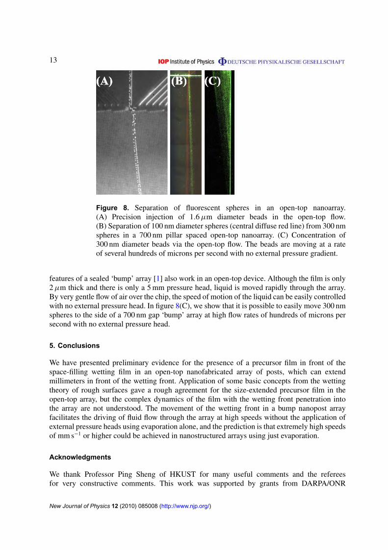
Figure 8. Separation of fluorescent spheres in an open-top nanoarray.(A) Precision injection of 1.6 µm diameter beads in the open-top flow.(B) Separation of 100 nm diameter spheres (central diffuse red line) from 300 nmspheres in a 700 nm pillar spaced open-top nanoarray. (C) Concentration of300 nm diameter beads via the open-top flow. The beads are moving at a rateof several hundreds of microns per second with no external pressure gradient.
features of a sealed ‘bump’ array [1] also work in an open-top device. Although the film is only2 µm thick and there is only a 5 mm pressure head, liquid is moved rapidly through the array.By very gentle flow of air over the chip, the speed of motion of the liquid can be easily controlledwith no external pressure head. In figure 8(C), we show that it is possible to easily move 300 nmspheres to the side of a 700 nm gap ‘bump’ array at high flow rates of hundreds of microns persecond with no external pressure head.
5. Conclusions
We have presented preliminary evidence for the presence of a precursor film in front of thespace-filling wetting film in an open-top nanofabricated array of posts, which can extendmillimeters in front of the wetting front. Application of some basic concepts from the wettingtheory of rough surfaces gave a rough agreement for the size-extended precursor film in theopen-top array, but the complex dynamics of the film with the wetting front penetration intothe array are not understood. The movement of the wetting front in a bump nanopost arrayfacilitates the driving of fluid flow through the array at high speeds without the application ofexternal pressure heads using evaporation alone, and the prediction is that extremely high speedsof mm s−1 or higher could be achieved in nanostructured arrays using just evaporation.
Acknowledgments
We thank Professor Ping Sheng of HKUST for many useful comments and the refereesfor very constructive comments. This work was supported by grants from DARPA/ONR
New Journal of Physics 12 (2010) 085008 (http://www.njp.org/)

14
(W911NF-05-1-0392, N00014-04-1-0776 and MDA972-00-1-0031), NSF Nanobiology Tech-nology Center (BSCECS9876771) and the state of New Jersey (NJCST 99-100-082-2042-007).
References
[1] Huang L R, Cox E C, Austin R H and Sturm J 2004 Continuous C particle separation through deterministiclateral displacement Science 304 987–90
[2] Barthlott W and Neinhuis C 1997 Purity of the sacred lotus, or escape from contamination in biologicalsurfaces Planta 202 1–8
[3] Oppenheim I and van Kampen N G 1983 The kinetic origin of the stick boundary condition Physica A122 277–85
[4] Matthews M T and Hill J M 2008 Nanofluidics and the Navier boundary condition Int. J. Nanotechnol.5 218–42
[5] Bocquet L and Barrat J L 2007 Flow boundary conditions from nano- to micro-scales Soft Matter 3 685–93[6] Cottin-Bizonne C, Barrat J L, Bocquet L and Charlaix E 2003 Low-friction E flows of liquid at nanopatterned
interfaces Nat. Mater. 2 237–40[7] Lide D R (ed) 2005 CRC Handbook of Chemistry and Physics, Internet Version 2005 (Boca Raton, FL: CRC
Press) http://www.hbcpnetbase.com[8] Purcell E M 1977 Life at low Reynolds number Am. J. Phys. 45 3–11[9] De Gennes P G 1985 Wetting—statics and dynamics Rev. Mod. Phys. 57 827–63
[10] Bonn D, Eggers J, Indekeu J, Meunier J and Rolley E 2009 Wetting and spreading Rev. Mod. Phys.81 739–805
[11] de Coninck J and Dunlop F 1987 Partial to complete wetting—a microscopic derivation of the Young relationJ. Stat. Phys. 47 827–49
[12] Ausserre D, Picard A M and Leger L 1986 Existence and role of the precursor film in the spreading of polymerliquids Phys. Rev. Lett. 57 2671–4
[13] Wenzel R N 1949 Surface roughness and contact angle J. Phys. Colloid Chem. 53 1466–7[14] McHale G, Shirtcliffe N J, Aqil S, Perry C C and Newton M I 2004 Topography driven spreading Phys. Rev.
Lett. 93 036102[15] Ishino C and Okumura K 2008 Wetting transitions on textured hydrophilic surfaces Eur. Phys. J. E 25 415–24[16] Ishino C, Reyssat M, Reyssat E, Okumura K and Quere D 2007 Wicking within forests of micropillars EPL
79 56005[17] Leger L, Erman M, Guinetpicard A M, Ausserre D and Strazielle C 1988 Precursor film profiles of spreading
liquid drops Phys. Rev. Lett. 60 2390–3[18] Courbin L, Denieul E, Dressaire E, Roper M, Ajdari A and Stone H A 2007 Imbibition by polygonal spreading
on microdecorated surfaces Nat. Mater. 6 661–4[19] Yu Z N, Chen L, Wu W, Ge H X and Chou S Y 2003 Fabrication of nanoscale gratings with reduced line edge
roughness using nanoimprint lithography J. Vac. Sci. Technol. B 21 2089–92[20] Murphy P F, Morton K J, Fu Z L and Chou S Y 2007 Nanoimprint mold fabrication and replication by
room-temperature conformal chemical vapor deposition Appl. Phys. Lett. 90 203115[21] Morton K J, Nieberg G, Bai S F and Chou S Y 2008 Wafer-scale patterning of sub-40 nm diameter and high
aspect ratio silicon pillar arrays by nanoimprint and etching Nanotechnology 19 345301
New Journal of Physics 12 (2010) 085008 (http://www.njp.org/)