the apache ignite book - leanpubsamples.leanpub.com/ignitebook-sample.pdf · apache ignite is one...
TRANSCRIPT

The Apache Ignite bookThe next phase of the distributed systems
Shamim Bhuiyan and Michael Zheludkov
This book is for sale at http://leanpub.com/ignitebook
This version was published on 2020-01-13
ISBN 978-0-359-43937-9
This is a Leanpub book. Leanpub empowers authors and publishers with the LeanPublishing process. Lean Publishing is the act of publishing an in-progress ebook usinglightweight tools and many iterations to get reader feedback, pivot until you have the rightbook and build traction once you do.
© 2018 - 2020 Shamim Bhuiyan

Tweet This Book!Please help Shamim Bhuiyan and Michael Zheludkov by spreading the word about thisbook on Twitter!
The suggested tweet for this book is:
Just purchased ”The Apache Ignite Book” https://leanpub.com/ignitebook by @shamim_ru#ApacheIgnite #IMDG #NoSQL #BigData #caching

To my Mother & Brothers, thank you for your unconditional love.

Contents
Preface . . . . . . . . . . . . . . . . . . . . . . . . . . . . . . . . . . . . . . . . . . . . . . iWhat this book covers . . . . . . . . . . . . . . . . . . . . . . . . . . . . . . . . . . . iCode Samples . . . . . . . . . . . . . . . . . . . . . . . . . . . . . . . . . . . . . . . . iiReadership . . . . . . . . . . . . . . . . . . . . . . . . . . . . . . . . . . . . . . . . . . iiiConventions . . . . . . . . . . . . . . . . . . . . . . . . . . . . . . . . . . . . . . . . . iiiReader feedback . . . . . . . . . . . . . . . . . . . . . . . . . . . . . . . . . . . . . . iv
About the authors . . . . . . . . . . . . . . . . . . . . . . . . . . . . . . . . . . . . . . . v
Chapter 4. Architecture deep dive . . . . . . . . . . . . . . . . . . . . . . . . . . . . . 1Understanding the cluster topology: shared-nothing architecture . . . . . . . . . . 1
Client and server node . . . . . . . . . . . . . . . . . . . . . . . . . . . . . . . . 2Embedded with the application . . . . . . . . . . . . . . . . . . . . . . . . . . . 5Client and the server nodes in the same host . . . . . . . . . . . . . . . . . . . 6Running multiple nodes within single JVM . . . . . . . . . . . . . . . . . . . . 6Real cluster topology . . . . . . . . . . . . . . . . . . . . . . . . . . . . . . . . . 7
Data partitioning in Ignite . . . . . . . . . . . . . . . . . . . . . . . . . . . . . . . . . 8Understanding data distribution: DHT . . . . . . . . . . . . . . . . . . . . . . . 9Rendezvous hashing . . . . . . . . . . . . . . . . . . . . . . . . . . . . . . . . . . 13
Durable memory architecture . . . . . . . . . . . . . . . . . . . . . . . . . . . . . . . 16Page . . . . . . . . . . . . . . . . . . . . . . . . . . . . . . . . . . . . . . . . . . . 17Data Page . . . . . . . . . . . . . . . . . . . . . . . . . . . . . . . . . . . . . . . . 18Index pages and B+ trees . . . . . . . . . . . . . . . . . . . . . . . . . . . . . . . 19Segments . . . . . . . . . . . . . . . . . . . . . . . . . . . . . . . . . . . . . . . . 20Region . . . . . . . . . . . . . . . . . . . . . . . . . . . . . . . . . . . . . . . . . . 21
Ignite read/write path . . . . . . . . . . . . . . . . . . . . . . . . . . . . . . . . . . . 23Write-Ahead-Log (WAL) . . . . . . . . . . . . . . . . . . . . . . . . . . . . . . . . . 26Baseline topology . . . . . . . . . . . . . . . . . . . . . . . . . . . . . . . . . . . . . . 32
Automatic cluster activation . . . . . . . . . . . . . . . . . . . . . . . . . . . . . 36

CONTENTS
Split-brain protection . . . . . . . . . . . . . . . . . . . . . . . . . . . . . . . . . 38Fast rebalancing and it’s pitfalls . . . . . . . . . . . . . . . . . . . . . . . . . . . 40
Chapter 5. Intelligent caching . . . . . . . . . . . . . . . . . . . . . . . . . . . . . . . . 41Smart caching . . . . . . . . . . . . . . . . . . . . . . . . . . . . . . . . . . . . . . . . 43
Caching best practices . . . . . . . . . . . . . . . . . . . . . . . . . . . . . . . . 44Design patterns . . . . . . . . . . . . . . . . . . . . . . . . . . . . . . . . . . . . 45Basic terms . . . . . . . . . . . . . . . . . . . . . . . . . . . . . . . . . . . . . . . 46
Database caching . . . . . . . . . . . . . . . . . . . . . . . . . . . . . . . . . . . . . . 46
Chapter 6. Database . . . . . . . . . . . . . . . . . . . . . . . . . . . . . . . . . . . . . . 50How SQL queries works in Ignite . . . . . . . . . . . . . . . . . . . . . . . . . . 50
Spring Data integration . . . . . . . . . . . . . . . . . . . . . . . . . . . . . . . . . . 64
Chapter 8. Streaming and complex event processing . . . . . . . . . . . . . . . . . . 66Kafka Streamer . . . . . . . . . . . . . . . . . . . . . . . . . . . . . . . . . . . . . . . 69
IgniteSourceConnector . . . . . . . . . . . . . . . . . . . . . . . . . . . . . . . . 69
Chapter 10. Management and monitoring . . . . . . . . . . . . . . . . . . . . . . . . . 72Managing Ignite cluster . . . . . . . . . . . . . . . . . . . . . . . . . . . . . . . . . . 73Monitoring Ignite cluster . . . . . . . . . . . . . . . . . . . . . . . . . . . . . . . . . 73
VisualVM . . . . . . . . . . . . . . . . . . . . . . . . . . . . . . . . . . . . . . . . 75Grafana . . . . . . . . . . . . . . . . . . . . . . . . . . . . . . . . . . . . . . . . . 79

PrefaceApache Ignite is one of the most widely used open source memory-centric distributed,caching, and processing platform. This allows the users to use the platform as an in-memory computing framework or a full functional persistence data stores with SQL andACID transaction support. On the other hand, Apache Ignite can be used for acceleratingexisting Relational and NoSQL databases, processing events & streaming data or developingMicroservices in fault-tolerant fashion.
This book addressed anyone interested in learning in-memory computing and distributeddatabase. This book intends to provide someone with little to no experience of ApacheIgnite with an opportunity to learn how to use this platform effectively from scratch takinga practical hands-on approach to learning.
What this book covers
Chapter 1. Introduction: gives an overview of the trends that have made in-memorycomputing such important technology today. By the end of this chapter, you will have aclear idea of what Apache Ignite is and why use Apache Ignite instead of others frameworkslike HazelCast, Ehcache?
Chapter 2. Getting started with Apache Ignite: is about getting excited. This chapter walksyou through the initial setup of an Ignite database and running of some sample application.You will implement your first Ignite application to read and write entries from the Cacheat the end of the chapter. Also, you will learn how to install and configure an SQL IDE torun SQL queries against Ignite caches and use Apache Ignite Thin client to working with theIgnite database.
Chapter 3. Apache Ignite use cases: discusses various design decisions and use cases whereIgnite can be deployed. These use cases detailed and explained through the rest of the book.
Chapter 4. Architecture deep dive: covers Ignite’s internal plumbing. This chapter has a lotof useful design concepts if you have never worked with a distributed system. This chapterintroduces Ignite shared nothing architecture, cluster topology, distributed hashing, Ignitereplication strategy and durable memory architecture. It is a theoretical chapter; you mayskip (not recommended) it and come back later.
Preface ii
Chapter 5. Intelligent caching: presents Ignite smart caching capabilities, Memoization,and Web-session clustering. This chapter covers developments and techniques to improvethe performance of your existing web applications without changing any code.
Chapter 6. Database: guides you through the Ignite database features. This massive chapterexplores: Ignite tables and index configurations, different Ignite queries, how SQL worksunder the cover, collocated/Non-collocated distributed joins, Spring data integration, usingIgnite with JPA and Ignite native persistence. This chapter is for you if you are planning touse Ignite as a database.
Chapter 7. Distributed computing: focuses on more advanced Ignite features such asdistributed computing and how Ignite can help you develop Micro-service like application,which will be performed in parallel fashion to gain high performance, low latency, and linearscalability. You will learn about Ignite inline MapReduce & ForkJoin, distributed closureexecution, continuous mapping for data processing across multiple nodes in the cluster.
Chapter 8. Streaming and complex event processing: takes the next step and goes beyondusing Apache Ignite to solve complex real-time event processing problem. This chaptercovers how Ignite can be used easily with other Big data technologies such as Kafka, flume,storm, and camel to solve various business problems. We will guide you through withcomplete examples for developing real-time data processing on Apache Ignite.
Chapter 9. Accelerating Big data computing: is a full chapter about how to use ApacheSpark Dataframe and RDD for processing massive datasets. We detailed by examples of howto share the application states in memory across multiple Spark jobs by using Ignite.
Chapter 10. Management and monitoring: explain the various tools that you can useto monitor and manage the Ignite cluster. For instance, configuring Zookeeper discovery,scaling up a cluster with Baseline topology.We provide a complete example of using Grafanafor monitoring Ignite cluster at the end of this chapter.
Code Samples
All code samples, scripts, and more in-depth examples can be found on the GitHubrepository¹.
¹https://github.com/srecon/the-apache-ignite-book

Preface iii
Readership
The target audiences of this book are IT architect, team leaders or programmer withminimum programming knowledge. No excessive knowledge is required, though it wouldbe good to be familiar with Java, Spring framework and tools like Maven. The book is alsouseful for any reader, who already familiar with Oracle Coherence, Hazelcast, Infinispan orMemcached.
Conventions
The following typographical conventions are used in this book:
Italic and Bold indicates new terms, important words, URL’s, filenames, and file extensions.
A block code is set as follows:
Listing 1.1
public class MySuperExtractor implements StreamSingleTupleExtractor<SinkRecord, String, S\tring> {
@Override publicMap.Entry<String, String> extract(SinkRecord msg) {String[] parts = ((String)msg.value()).split("_");return new AbstractMap.SimpleEntry<String, String>(parts[1], parts[2]+":"+parts[3]);
}}
Any command-line input or output is written as follows:
[2018-09-30 15:39:04,479] INFO Kafka version : 2.0.0 (org.apache.kafka.common.utils.AppIn\foParser)[2018-09-30 15:39:04,479] INFO Kafka commitId : 3402a8361b734732 (org.apache.kafka.common\.utils.AppInfoParser)[2018-09-30 15:39:04,480] INFO [KafkaServer id=0] started (kafka.server.KafkaServer)
TipThis icon signifies a tip, suggestion.
Preface iv
WarningThis icon indicates a warning or caution.
InfoThis icon signifies general note.
Reader feedback
Wewould like to hear your comment such as what you think, like or dislike about the contentof the book. Your feedback will help us to write a better book and help others to clear all theconcepts. To submit your feedback, please use the the feedback link².
²https://leanpub.com/ignitebook/email_author/new

About the authorsShamim Bhuiyan is currently working as an Enterprise architect; where he’s responsible fordesigning and building out highly scalable, and high-load middleware solutions. He receivedhis Ph.D. in Computer Science from the University of Vladimir, Russia in 2007. He has beenin the IT field for over 18 years and is specialized in Middleware solutions, Big Data andData science. Also, he is a former SOA solution designer, speaker, and Big data evangelist.Actively participates in the development and designing of high-performance software forIT, telecommunication and the banking industry. In spare times, he usually writes the blogfrommyworkshop³ and shares ideas with others.
Michael Zheludkov is a senior programmer at AT Consulting. He graduated from the Bau-man Moscow State Technical University in 2002. Lecturer at BMSTU since 2013, deliveringcourse Parallel programming and distributed systems.
³http://frommyworkshop.blogspot.ru/

Chapter 4. Architecture deep diveApache Ignite is an open-source memory-centric distributed database, caching and comput-ing platform. It was designed as an in-memory data grid for developing a high-performancesoftware system from the beginning. So its core architecture design is slightly different fromthat of the traditional NoSQL databases, able to simplify the building of modern applicationswith a flexible data model and simpler high availability and high scalability.
To understand how to properly design an application with any databases or framework,you must first understand the architecture of the database or framework itself. By getting abetter idea of the system, you can solve different problems in your enterprise architecturelandscape, can select a comprehensive database or framework that is appropriate for yourapplication and can get maximum benefits from the system. This chapter gives you a look atthe Apache Ignite architecture and core components to help you figure out the key reasonsbehind Ignite’s success over other platforms.
Understanding the cluster topology:shared-nothing architecture
Apache Ignite is a grid technology, and its design implies that the entire system is bothinherently available and massively scalable. Grid computing is a technology in which weutilize the resources of many computers (commodity, on-premise, VM, etc.) in a networktowards solving a single computing problem in parallel fashion.
Note that there is often some confusion about the difference between grid and cluster.Grid computing is very similar to cluster computing, the big difference being that clustercomputing consists of homogeneous resources, while grids are heterogeneous. Computersthat are part of a grid can run different operating systems and have different hardware,whereas cluster computers all have the same hardware and OS. A grid can make use of sparecomputing power on a desktop computer, while the machines in a cluster are dedicated toworking as a single unit and nothing else. Throughout this book, we use the terms grid andcluster interchangeably.
Apache Ignite also provides a shared-nothing architecture⁴ where multiple identical nodes
⁴https://en.wikipedia.org/wiki/Shared-nothing_architecture

Chapter 4. Architecture deep dive 2
form a cluster with no single master or coordinator. All nodes in a shared-nothing cluster areidentical and run the exact same process. In the Ignite grid, nodes can be added or removednondisruptively to increase (or decrease) the amount of RAM available. Ignite internodecommunication allows all nodes to receive updates quickly without having any mastercoordinator. Nodes communicate using peer-to-peer message passing. The Apache Ignitegrid is sufficiently resilient, allowing the nondisruptive automated detection and recoveryof a single node or multiple nodes.
On the most fundamental level, all nodes in the Ignite cluster fall into one of two categories:client and server. There is a big difference between the two types of nodes, and they can bedeployed in different ways. In the rest of this section, we will talk about the topology of theIgnite grid and how it can be deployed in real life.
Client and server node
An Ignite node is a single Ignite process running in a JVM. Apache Ignite nodes have anoptional notion of client and server nodes as we mentioned before. Often, an Ignite clientnode also addresses as a native client node. Both client and server nodes are part of Ignite’sphysical grid and are interconnected with each other. The client and server nodes have thefollowing characteristics.
Node DescriptionServer 1. Acts as a container for storing data and computing. A server node contains data,
participates in caching, computing and streaming. 2. Generally starts as a standaloneJava process.
Client 1. Acts as an entry point to run operations like put/get into the cache. 2. Can storeportions of data in the near cache, which is a smaller local cache that stores mostrecently and most frequently accessed data. 3. It is also used to deploy compute andservice tasks to the server nodes and can participate in computation tasks (optional). 4.Usually embedded with the application code.
TipYou often encounter the term data node in the Ignite documentation. The termsdata node and server node refer to the same thing and are used interchangeably.
All nodes in the Ignite grid start as server nodes by default, and client nodes need to beexplicitly enabled. You can imagine the Ignite client node as a thick client (also called a fatclient, e.g., Oracle OCI8). Whenever a client node connects to the Ignite grid or cluster, it is

Chapter 4. Architecture deep dive 3
aware of the grid topology (data partitions for each node) and is able to send a request to theparticular node to retrieve data. You can configure an Ignite node to be either a client or aserver via a Spring or Java configuration, as shown below.
Spring configuration:
Listing 4.1
<bean class="org.apache.ignite.configuration.IgniteConfiguration">...<!-- Enable client mode. --><property name="clientMode" value="true"/>...
</bean>
Java configuration:
Listing 4.2
IgniteConfiguration cfg1 = new IgniteConfiguration();cfg1.setGridName("name1");// Enable client mode.cfg1.setClientMode(true);// Start Ignite node in client modeIgnite ignite1 = Ignition.start(cfg1);
Here is also a special type of logical node called a compute node in the Ignite cluster. Acompute node is the node that usually participates in computing business logic. Basically, aserver node that contains data is also used to execute computing tasks.

Chapter 4. Architecture deep dive 4
Figure 4.2
However, an Apache Ignite client node can also participate in computing tasks optionally.The concept might seem complicated at first glance, but let’s try to clarify it.
Server nodes or Data nodes always stores data and participating in any computing task.On the other hand, the Client node can manipulate the server caches, store local data andoptionally participate in computing tasks. Usually, client nodes are only used to put orretrieve data from the caches.
Why should you want to run any computing task on client nodes? In some cases (for instancehigh volume transactions in the server nodes), you do not want to execute any job orcomputing task on the server nodes. In such a case, you can choose to perform jobs onlyon client’s nodes by creating a cluster group. This way, you can separate the server node(data node) from the nodes that are particular uses for computing in the same grid.
A cluster group is a logical unit of a few nodes (server or client node) that group together ina cluster to perform some work. Within a cluster group, you can limit job execution, servicedeployment, streaming and other tasks to run only within a cluster group. You can createa cluster group based on any predicate. For instance, you can create a cluster group froma group of nodes, where all the nodes are responsible for caching data for a cache namedtestCache. It’s enough for now, and we will explore this distinction later in the subsequentsection of this chapter.
Ignite nodes can be divided into two major groups from the deployment point of view:
1. Embedded with the application.2. Standalone server node.

Chapter 4. Architecture deep dive 5
Embedded with the application
Apache Ignite as a Java application can be deployed embedded with other applications. Itmeans that Ignite nodes will be runs on the same JVM that uses the application. Ignite nodecan be embedded with any Java web application artifact like WAR or EAR running on anyapplication server or with any standalone Java application. Our HelloIgnite Java applicationfrom chapter 2 is a perfect example of embedded Ignite server. We start our Ignite server asa part of the Spring application running on the same JVM and joins with other nodes of thegrids in this example. In this approach, the life cycle of the Ignite node is tightly bound withthe life cycle of the entire application itself. Ignite node will also shut down if the applicationdies or is taken down. This topology is shown in figure 4.3.
Figure 4.3
If you change the IgniteConfiguration.setClientMode property to false, and rerun theHelloIgnite application, you should see the following:
Figure 4.4
HelloIgnite Java application run and joins to the cluster as a server node. The applicationexists from the Ignite grid after inserting a few datasets. Another excellent example ofusing Ignite node as an embedded mode are implementing web session clustering. In this

Chapter 4. Architecture deep dive 6
approach, you usually configure (web.xml file) your web application to start an Ignite nodein embedded mode. When multiple application server instances are running, all embeddedIgnite nodes connect with each other and forming an Ignite grid. Please see the chapter 5Intelligent caching for more details of using web session clustering.
Client and the server nodes in the same host
This is one of the typical cases when Ignite client and server nodes are running on differentJVM in the same host. You can execute Ignite client and server nodes in separate containerssuch as Docker or OpenVZ if you are using container technology for running JVM. Bothcontainers can be located in the same single host.
Figure 4.5
The container isolates the resources (CPU, RAM, Network interface) and the JVM only usesisolated resources assigned to this container. Moreover, the Ignite client and server node canbe deployed in the separate JVM in the single host without containers, where they all usethe shared resourced assigned to this host machine. Host machine could be any on-premise,virtual machine or Kubernates pods.
Running multiple nodes within single JVM
It is possible to start multiple nodes from within a single JVM. This approach is very popularfor unit testing among developers. Ignite nodes running on the same JVM connects with

Chapter 4. Architecture deep dive 7
each other and forming an Ignite grid.
Figure 4.6
One of the easiest ways to run a few nodes within a single JVM is by executing the followingcode::
Listing 4.3
IgniteConfiguration cfg1 = new IgniteConfiguration();cfg1.setGridName("g1");Ignite ignite1 = Ignition.start(cfg1);IgniteConfiguration cfg2 = new IgniteConfiguration();cfg2.setGridName("g2");Ignite ignite2 = Ignition.start(cfg2);
TipSuch a configuration is only intended for developing process and not recom-mended for production use.
Real cluster topology
In this approach Ignite client and server nodes are running on different hosts. These arethe most common way to deploy a large-scale Ignite cluster for production use because itprovides greater flexibilities in term of cluster technics. Individual Ignite server node can betaken down or restarted without any impact to the overall cluster.

Chapter 4. Architecture deep dive 8
Figure 4.6.1
Such a cluster can be quickly deployed in and maintained by the kubernates⁵ which an opensource system for automating deployment, scaling, and management of the containerizedapplication. VMWare⁶ is another common cluster management system rapidly used for theIgnite cluster.
Data partitioning in Ignite
Data partitioning⁷ is one of the fundamental parts of any distributed database despite itsstorage mechanism. Data partitioning and distribution technics are capable of handling largeamounts of data across multiple data centers. Also, these technics allow a database systemto become highly available because data has been spread across the cluster.
Traditionally, it has been difficult to make a database highly available and scalable, especiallythe relational database systems that have dominated the last couple of decades. Thesesystems are most often designed to run on a single large machine, making it challengingto scale out to multiple machines.
At the very high level, there are two styles of data distribution models available:
⁵https://kubernetes.io⁶https://www.vmware.com/solutions/virtualization.html⁷https://en.wikipedia.org/wiki/Partition_(database)

Chapter 4. Architecture deep dive 9
1. Sharding: it’s sometimes called horizontal partitioning. Sharding distributes differentdata across multiple servers, so each server act as a single source for a subset of data.Shards are called partitions in Ignite.
2. Replication: replication copies data across multiple servers, so each portion of datacan be found in multiple places. Replicating each partition can reduce the chance of asingle partition failure and improves the availability of the data.
TipThere are also two types of partitions available in partitions strategy: verticalpartitioning and functional partition. A detailed description of these partitioningstrategies is out of the scope of this book.
Usually, there are several algorithms uses for distributing data across the cluster, a hashingalgorithm is one of them. We will cover the Ignite data distribution strategy in this section,which will build a deeper understanding of how Ignite manages data across the cluster.
Understanding data distribution: DHT
As you read in the previous section, Ignite shards are called partitions. Partitions are memorysegments that can contain a large volume of a dataset, depends on the capacity of the RAMof your system. Partition helps you to spread the load over more nodes, which reducescontention and improves performance. You can scale out the Ignite cluster by adding morepartitions that run on different server nodes. The next figure shows an overview of thehorizontal partitioning or sharding.
Figure 4.7

Chapter 4. Architecture deep dive 10
In the above example, the client profile’s data are divided into partitions based on the clientId key. Each partition holds the data for a specified range of partition key, in our case, it’s therange of the client ID key. Note that, partitions are shown here for the descriptive purpose.Usually, the partitions are not distributed in any order but are distributed randomly.
Distributed Hash Table⁸ or DHT is one of the fundamental algorithms used in the distributedscalable system for partitioning data across the cluster. DHT is often used in web caching,P2P system, and distributed database. The first step to understand the DHT is Hash Tables.Hashtable⁹ needs key, value, and one hash function, where hash function maps the key to alocation (slot) where the value is located. According to this schema, we apply a hash functionto some key attribute of the entity we are storing that becomes the partition number. Forinstance, if we have four Ignite nodes and 100 clients (assume that client Id is a numericvalue), then we can apply the hash function hash (Client Id) % 4, which will return the nodenumber where we can store or retrieve the data. Let’s begin with some basic details of theHashtable.
The idea behind the Hashtable is straightforward. For each element we insert, we have tohave calculated the slot (technically, each position of the hash table is called slot) numberof the element into the array, where we would like to put it. Once we need to retrieve theelement from the array, we recalculate its slot again and returns it’s as a single operation(something like return array [calculated index or slot]). That’s why it has O(1)¹⁰ timecomplexity. In short, O(1) means that the operation takes a certain (constant) amount oftimes, like 10 nanoseconds or 2 milliseconds. The process of calculating unique slot of eachelement is called Hashing and the algorithm how it’s done called Hash function.
In a typical Hash table design, the Hash function result is divided by the number of arrayslots and the remainder of the division becomes the slot number of the array. So, the indexor slot into the array can be calculated by hash(o) % n, where o is the object or key, and n is thetotal number of slots into the array. Consider the following illustration below as an exampleof the hash table.
⁸https://en.wikipedia.org/wiki/Distributed_hash_table⁹https://en.wikipedia.org/wiki/Hash_table¹⁰https://en.wikipedia.org/wiki/Big_O_notation

Chapter 4. Architecture deep dive 11
Figure 4.8
The value on the left represents keys in the preceding diagram, which are being hashed bythe hash function for producing the slot where the value is stored. Based on the hash valuecomputed, all the items placed in respective slots. Also, we can look up the client profile ofa given client Id by calculating its hash and then accessing the resulting slot into the array.
InfoImplementation of the Hash tables has some memory overhead. Hash tables needa lot of memory to accommodate the entire. Even if most of the table is empty,we need to allocate memory for the entire table. Often, this called a time-spacetradeoff, and hashing gives the best performance for searching data at the expanseof memory.
Hash table is well suited for storing data set allocated in one machine. However, when youhave to accommodate a large number of keys, for instance, millions and millions of keys,DHT comes into play. A DHT is merely a key-value store distributed across many nodes ina cluster. You have to divide the keys into subsets of keys and map those keys to a bucket.Each bucket will reside in a sperate node. You can assume a bucket as a sperate hash table.In one word, using buckets to distribute the key-value pairs is DHT.
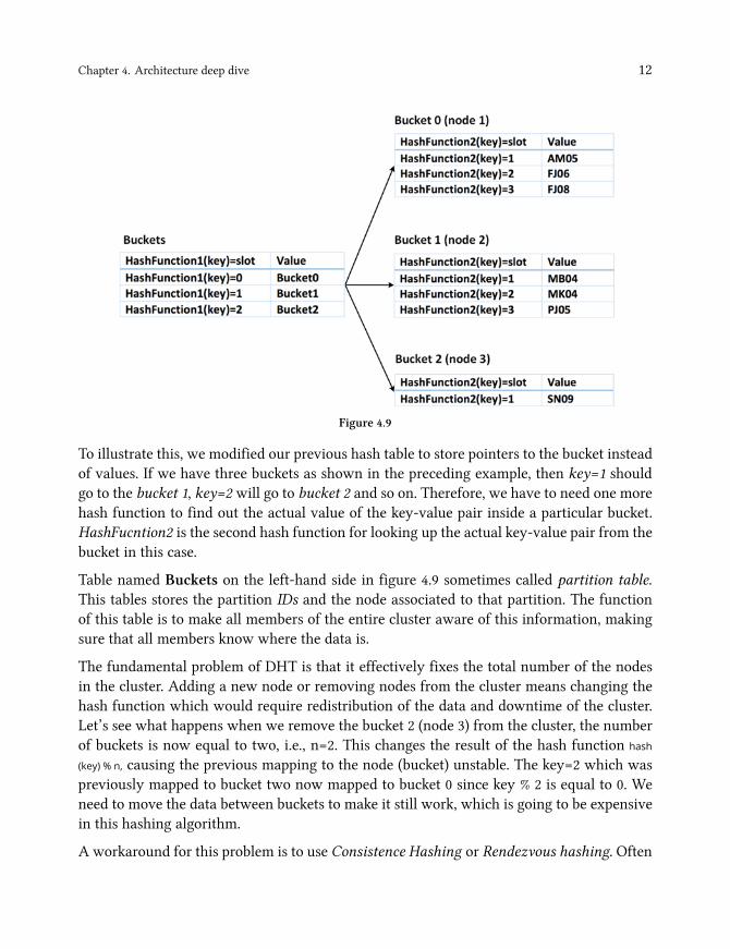
Another key objective of the hash function in a DHT is to map a key to the node that owns it,such that a request can be made to the correct node. Therefore, there are two hash functionsfor looking up the value of the key across the cluster in DHT. The first hash function willsearch for the appropriate bucket maps to the key, and the second hash function will returnthe slot number of the value for the key located in the node. We can visualize the schema asshown in figure 4.9.
Chapter 4. Architecture deep dive 12
Figure 4.9
To illustrate this, we modified our previous hash table to store pointers to the bucket insteadof values. If we have three buckets as shown in the preceding example, then key=1 shouldgo to the bucket 1, key=2 will go to bucket 2 and so on. Therefore, we have to need one morehash function to find out the actual value of the key-value pair inside a particular bucket.HashFucntion2 is the second hash function for looking up the actual key-value pair from thebucket in this case.
Table named Buckets on the left-hand side in figure 4.9 sometimes called partition table.This tables stores the partition IDs and the node associated to that partition. The functionof this table is to make all members of the entire cluster aware of this information, makingsure that all members know where the data is.
The fundamental problem of DHT is that it effectively fixes the total number of the nodesin the cluster. Adding a new node or removing nodes from the cluster means changing thehash function which would require redistribution of the data and downtime of the cluster.Let’s see what happens when we remove the bucket 2 (node 3) from the cluster, the numberof buckets is now equal to two, i.e., n=2. This changes the result of the hash function hash
(key) % n, causing the previous mapping to the node (bucket) unstable. The key=2 which waspreviously mapped to bucket two now mapped to bucket 0 since key % 2 is equal to 0. Weneed to move the data between buckets to make it still work, which is going to be expensivein this hashing algorithm.
A workaround for this problem is to use Consistence Hashing or Rendezvous hashing. Often
Chapter 4. Architecture deep dive 13
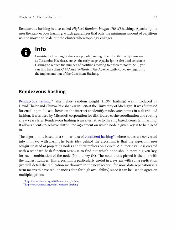
Rendezvous hashing is also called Highest Random Weight (HRW) hashing. Apache Igniteuses the Rendezvous hashing, which guarantees that only the minimum amount of partitionswill be moved to scale out the cluster when topology changes.
InfoConsistence Hashing is also very popular among other distributive systems suchas Cassandra, Hazelcast, etc. At the early stage, Apache Ignite also used consistentHashing to reduce the number of partitions moving to different nodes. Still, youcan find Java class GridConsistentHash in the Apache Ignite codebase regards tothe implementation of the Consistent Hashing.
Rendezvous hashing
Rendezvous hashing¹¹ (aka highest random weight (HRW) hashing) was introduced byDavid Thaler and Chinya Ravishankar in 1996 at the University of Michigan. It was first usedfor enabling multicast clients on the internet to identify rendezvous points in a distributedfashion. It was used by Microsoft corporation for distributed cache coordination and routinga few years later. Rendezvous hashing is an alternative to the ring based, consistent hashing.It allows clients to achieve distributed agreement on which node a given key is to be placedin.
The algorithm is based on a similar idea of consistent hashing¹² where nodes are convertedinto numbers with hash. The basic idea behind the algorithm is that the algorithm usesweights instead of projecting nodes and their replicas on a circle. A numeric value is createdwith a standard hash function hash(Ni, K) to find out which node should store a given key,for each combination of the node (N) and key (K). The node that’s picked is the one withthe highest number. This algorithm is particularly useful in a system with some replication(we will detail the replication mechanism in the next section, for now, data replication is aterm means to have redundancies data for high availability) since it can be used to agree onmultiple options.
¹¹https://en.wikipedia.org/wiki/Rendezvous_hashing¹²https://en.wikipedia.org/wiki/Consistent_hashing
Chapter 4. Architecture deep dive 14
Figure 4.10
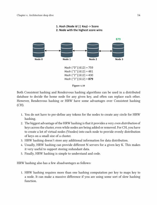
Both Consistent hashing and Rendezvous hashing algorithms can be used in a distributeddatabase to decide the home node for any given key, and often can replace each other.However, Rendezvous hashing or HRW have some advantages over Consistent hashing(CH).
1. You do not have to pre-define any tokens for the nodes to create any circle for HRWhashing.
2. The biggest advantage of theHRWhashing is that it provides a very even distribution ofkeys across the cluster, evenwhile nodes are being added or removed. For CH, you haveto create a lot of virtual nodes (Vnodes) into each node to provide evenly distributionof keys on a small size of a cluster.
3. HRW hashing doesn’t store any additional information for data distribution.4. Usually, HRW hashing can provide different N servers for a given key K. This makes
it very useful to support storing redundant data.5. Finally, HRW hashing is simple to understand and code.
HRW hashing also has a few disadvantages as follows:
1. HRW hashing requires more than one hashing computation per key to maps key toa node. It can make a massive difference if you are using some sort of slow hashingfunction.
Chapter 4. Architecture deep dive 15
2. HRW hashing can be slower to run hash functions against each key node combinationsinstead of the just once with the CH algorithms.
Rendezvous Hashing or HRW hashing is the default algorithm in Apache Ignite for akey to node mapping since version 2.0. RendezvousAffinityFunction¹³ class is the standardimplementation of the Rendezvous Hashing in the Apache Ignite. This class provides affinityinformation for detecting which node (nodes) are responsible for the particular key in theIgnite grid.
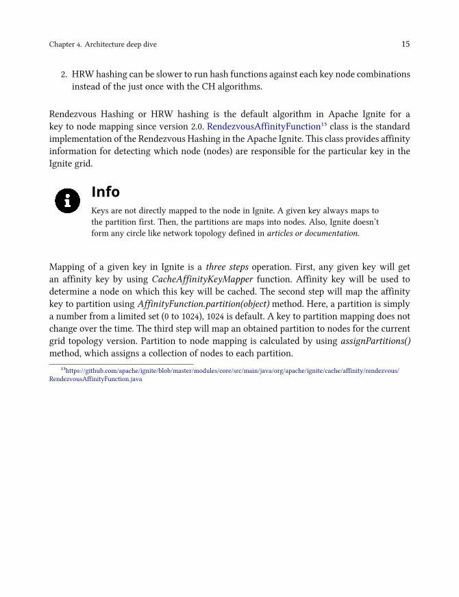
InfoKeys are not directly mapped to the node in Ignite. A given key always maps tothe partition first. Then, the partitions are maps into nodes. Also, Ignite doesn’tform any circle like network topology defined in articles or documentation.
Mapping of a given key in Ignite is a three steps operation. First, any given key will getan affinity key by using CacheAffinityKeyMapper function. Affinity key will be used todetermine a node on which this key will be cached. The second step will map the affinitykey to partition using AffinityFunction.partition(object) method. Here, a partition is simplya number from a limited set (0 to 1024), 1024 is default. A key to partition mapping does notchange over the time. The third step will map an obtained partition to nodes for the currentgrid topology version. Partition to node mapping is calculated by using assignPartitions()method, which assigns a collection of nodes to each partition.
¹³https://github.com/apache/ignite/blob/master/modules/core/src/main/java/org/apache/ignite/cache/affinity/rendezvous/RendezvousAffinityFunction.java

Chapter 4. Architecture deep dive 16
Figure 4.11
Apache Ignite affinity function (key to node mapping) is fully pluggable, and you canimplement your version of Rendezvous Hashing or consistent hashing to determine an idealmapping for the partition to nodes in the grids. Youmust have implemented the Java interfaceAffinityFuction and configure this function in the cache configuration as shown below:
Durable memory architecture
The Ignite new memory architecture as well as native persistence was debuted on version2.0 and distributed from the end of the last year. The data in memory and on disk has thesame binary representation. This means that no additional conversion of the data is neededwhile moving from in memory to disk. Ignite new memory architecture provides off-heapdata storage in a page format. Sometimes it’s also called page-based memory architecture
Chapter 4. Architecture deep dive 17
that is split into pages of fixed size. The pages are allocated in managed off-heap (outside ofthe Java heap) region of the RAM and organized in a particular hierarchy. Let’s start withthe basic of the durable memory architecture: page, the smallest unit of the data with a fixedsize.
Page
A page is a basic storage unit of data that contains actual data or meta-data. Each pagecontains a fixed length and has a unique identifier: FullPageId. As mentioned earlier, Pagesare stored outside the Java heap and organized in RAM. Pages interact with the memoryusing the PageMemory abstraction. It usually helps to read, write a page and even allocate apage ID.
When the allocated memory exhausted and the data are pushed to the persistence store,it happens page by page. So, a page size is crucial for performance, it should not be toolarge, otherwise, the efficiency of swapping will suffer seriously. When page size is small,there could be another problem of storing massive records that do not fit on a single page.Because, to satisfy a read, Ignite have to do a lot of expensive calls to the operating systemfor getting small pages with 10-15 records.
When the record does not fit in a single page, it spreads across several pages, each of themstores only some fragments of the record. The downside of this approach is that Ignite hasto look up the multiple pages to obtain the entire records. So, you can configure the size ofthe memory page in such cases.
Size of the page can be configured via DataStorageConfiguration.setPageSize(..) parameter.It is highly recommended to use the same page size or not less than of your storage device(SSD, Flash, etc.) and the cache page size of your operating system. Try a 4 KB as page sizeif it’s difficult to figure out the size of the cache page size of your operating system,.
Every page contains at least two sections: header and page data. Page header includes thefollowing information’s:
1. Type: size 2 bytes, defines the class of the page implementation (ex. DataPageIO,BplusIO)
2. Version: size 2 bytes, defines the version of the page3. CRC: size 4 bytes, defines the checksum4. PageId: unique page identifier5. Reserved: size 3*8 bytes

Chapter 4. Architecture deep dive 18
Ignite memory page structure illustrated in the following figure 4.29.
Figure 4.28
Memory pages are divided into several types, and the most important of them are Data Pagesand Index Pages. All of them are inherited from the PageIO. We are going to details the DataPage and the Index Page in the next two subsections.
Data Page
The data pages store the data you enter into the Ignite caches. If a single record does notfit into a single data page, it will be stored into several data pages. Generally, a single datapage holds multiple key-values entries to utilize the memory as efficiently as possible foravoiding memory fragmentation. Ignite looks for an optimal data page that can fit the entirekey-value pair when a new key-value entry is being added to the cache. It makes sense toincrease the page size if you have many large entries in your application. One thing we haveto remember is that data is swapped to disk page by page and the page is either completelylocated in RAM or into Disk.
Figure 4.29
During an entry updates, if the entry size exceeds the free space available in the data page,then Ignite will look for a new data page that has enough space to store the entry and the newvalue will be moved there. Data page has its header information in addition to the abstractpage. Data page consist of two major sections: the data page header and data page data.Data page header contains the following information’s and the structure of the data page isillustrated in figure 4.29.
1. Free space, refers to the max row size, which is guaranteed to fit into this data page.2. Direct count.

Chapter 4. Architecture deep dive 19
3. Indirect count.
The next portions of data after the page header is data page data and consists of items andvalues. Items are linked to the key-value. A link allows reading key-value pair as an Nʰ itemin a page. Items are stores from the beginning to the end, and values are stores on reverseorder: from the end to beginning.
Index pages and B+ trees
Index pages are stored in a structure known as a B+ tree¹⁴, each of them can be distributedacross multiple pages. All SQL and cache indexes are stored and maintained in B+ tree datastructure. For every unique index declared in SQL schema, Ignite initialized and managed adedicated B+ tree instance. Unlike data pages, index pages are always stored in memory forquick access when looking for data.
A B+ tree structure is very similar to a B tree with the difference that an additional levelis added at the bottom with linked leaves. The purpose of the B+ tree is to link and orderthe index pages that are allocated and stored within the durable memory. This means thatonly a small number of pointers or links traversal is necessary to search for value if thenumber of the keys in a node is very large. Finally, the index pages of the B+ tree all containa next sibling pointer for fast iteration through a contiguous block of value. This allows forextremely fast range queries.
InfoKey duplication is not possible in B+ tree structure.
In B+ tree binary search is used to find out the required key. To search for an element intothe tree, one load up the root nodes finds the adjacent keys that the searched-for value isbetween. If the required value is not found, it is compared with other values in the tree.
¹⁴https://en.wikipedia.org/wiki/B%2B_tree

Chapter 4. Architecture deep dive 20
Figure 4.30
There is a high cost of allocating memory for a large number of pages including data or indexpages, which solves through the next level of abstraction called Segments.
Segments
Segments are a contiguous block of physical memory, which are the atomic units of theallocated memory. When the allocated memory runs out, the operating system is requestedfor an additional segment. Further, this segment is divided into pages of fixed size. All pagetypes include data or index pages resides in the segment.
Figure 4.31
It is possible to allocate up to 16 memory segments for one dedicated memory region withthe size of the segments at least 256 MB in the current version. Ignite uses a particularcomponent for managing information about pages currently available in memory segmentand page Id mapping to region address called LoadedPagesTable. LoadedPagesTable orPageIdTable manages mapping from Page ID to relative memory segment chunk (unsafe).
Chapter 4. Architecture deep dive 21
LoadedPagesTable uses Robin Hood Hashing¹⁵ algorithm for maintaining HashMap ofFullPageId since Ignite version 2.5.
When it comes about memory segment, it is necessary to mention the memory consumptionlimits. In Apache Ignite data are stored in caches. Obviously, we cannot keep the entiredataset forever in memory. Also, different data may have different storage requirements.To make it possible to set limits at the level of each cache, a hybrid approach was chosenthat allows Ignite to define limits for groups of caches, which brings us to the next level ofabstraction called memory Region.
Region
The top level of the Ignite durable memory storage architecture is the data Region, a logicalexpandable area. Data region can have a few memory segments and can group segmentsthat share a single storage area with their settings, constraints and so on. Durable memoryarchitecture can consist of multiple data regions that can vary in size, evictions policies andcan be persisted on disk.
TipIgnite allocates a single data region (default data region) occupying up to 20% ofthe RAM available on a local cluster by default. The default data region is the dataregion that is used for all the caches that are not explicitly assigned to any otherdata region.
Data region encapsulates all the data storage configuration for operational and historicaldata for your utilization in Ignite and can have one or more caches or tables on a singleregion. With data region configuration you can manage more than one data region, whichcan be used for storing historical and operation data of your system. There are differentcases when you might do this. The most trivial example is that when you have differentnon-related caches or tables with different limits.
¹⁵http://codecapsule.com/2013/11/17/robin-hood-hashing-backward-shift-deletion/

Chapter 4. Architecture deep dive 22
Figure 4.32
Let’s assume that in our application we have Product, Purchase history entities storedin ProductCache and PurchaseHistCache caches respectively. Here, the Product data isoperational and access by the application frequently. Moreover, the Purchase History dataneeded occasionally and not very critical to lose. In this situation, we can define two differentregions of memory with different sizes: Data_region_4GB and Data_region_128GB.
• Data_region_128GB is only 128 GB of memory and will store the operational orfrequently access data such as Products.
• Data_region_4GB size is 4 GB and will be allocated for rarely accessed data sets likePurchase history.
Figure 4.33
When we create caches, we should have specified the region, on which the cache will belongto. The limits here are applied on the data region level. When you put or insert something inyour small cache, and if you exceed the maximum size of the data region (ex. 4 GB), you willget out of the memory (IgniteOutOfMemory) exception, even when the larger data region isempty. You can’t use the memory that is allocated for the Data_region_128GB by the smallcaches, because it is assigned to the different data region.
So, you should remove or swap the stale data from the data region if you want to avoid thisout of memory error. For these circumstances, Ignite provides a few data eviction algorithmsto remove unnecessary data from in memory.

Chapter 4. Architecture deep dive 23
Ignite read/write path
Ignite uses a B+ tree index to find out the potential data pages to fulfil a read. Ignite processesread data at several stages on the read path to discover where the data is stored, startinglooking up the key in the B+ tree and finishing with data page:
1. On the client node, a cache method has been called myCache.get(keyA).2. Client node identifies the server node that is responsible for this given key keyA using
the built-in affinity function and delegates the request to the server node over thenetwork.
3. The server node determines thememory region that is responsible for the cachemyCache.4. In the corresponding memory region, a request goes to the meta page, which contains
the entry points to a B+ tree by the key of this cache.5. Based on the keyA hash code, the index page the key belongs to will be located in the
B+ tree.6. Ignite will return a null value if the corresponding index page is not found in the
memory or on the disk.7. If the index page exists, then it contains the reference to the data page of the entry keyA.8. Ignite accesses the data page for keyA and returns the value to the client node.
The above schema for data looks up by the key can be illustrated as shown in figure 4.38.

Chapter 4. Architecture deep dive 24
Figure 4.37
Similar to the read path, Ignite processes data at several stages on a write path. The onlydifference is that, when a write occurs, Ignite looks for the corresponding index page in theB+ tree. If the index page is not found, Ignite requests a new index page from one of the freelists. The same thing happens for the data page. Also, a new data page also requests from thefree list.
Free List is a list of pages, structured by an amount of space remained within a page. Ignitemanages free lists to solve the problem of fragmentation in pages (not full page). Free listsmake the allocation and deallocation operations of the data and index pages straightforward,and allow to keep track of free memory. For instance, the image in figure 4.39 shows a freelist that stores all the data pages that have up to 15% free space available. Data and indexpages are tracked in separate free lists. The list is traversed, and the data/index page that islarge enough to store the data is returned when a request for a data/index pages is sent.

Chapter 4. Architecture deep dive 25
Figure 4.38
Let’s see what’s going under the hood when a myCache.put(keyA, valueA) request sent to the Ignitenode:
1. A cache method myCache.put(keyA, valueA) has been called on the client node.2. Client node identifies the server node that is responsible for this given key keyA using
the built-in affinity function and delegates the request to the server node over thenetwork.
3. The server node determines thememory region that is responsible for the cachemyCache.4. A request goes to the Meta page in the corresponding memory region, which contains
the entry points to a B+ tree by the key of this cache.5. Based on the keyA hash code, the index page the key belongs to will be located in the
B+ tree.6. If the corresponding index page is not found in the memory or on disk, then a new
page will be requested from one of the free lists. Once the index page is provided, itwill be added to the B+ tree.
7. If the index page is empty (i.e., does not refer to any data page), then the data page willbe provided by one of the free lists, depending on the total cache entry size. During theselection of the data page for storing the new key-value pair, Ignite does the following:
• Consult marshaller about size in bytes of this value pair.• Upper-round this value to be divisible by 8 bytes.• Use the value from the previous step to get page list from the free list.• Select some page from an appropriate list of free pages. This page will haverequired amount of free space.
• A reference to the data page will be added to the index page.

Chapter 4. Architecture deep dive 26
8. The cache entry is added to the data page.
The Ignite write path with several stages illustrated in the following sequence diagram.
Figure 4.39
Write-Ahead-Log (WAL)
The Write-Ahead-Log or WAL is a commonly used technique in the database system formaintaining atomicity and durability of writes. The key behind the WAL is that beforemaking any changes to database state, first, we have to log the complete set of operations tothe nonvolatile storage (e.g., disk). By writing the log into WAL first, we can guarantee thedata durability. If the database crash during changes to the disk, we will be able to read andreplay the instructions from the WAL to recover the mutation.
TipWAL also known as the transaction log or redo log file. Practically every databasemanagement system has one.
From the Apache Ignite perspective, WAL is a dedicated partition file stored on each clusternode. The update is not directly written to the appropriate partition file but is appended tothe end of theWAL file when data are updated in RAM.WAL provides superior performancewhen compared to in-place updates.
So, what exactly is a Write-Ahead-Log (WAL) file and how it works? Let’s consider anapplication that’s trying to change the value of A and B from the following four key-values:

Chapter 4. Architecture deep dive 27
(K, V) = (A, 10);(K, V) = (B, 10);(K, V) = (C, 20);(K, V) = (D, 30);
The application is performing an addition of 10 within a single transaction as shown below.
A := A+ 10;B := B + 10;
The problem arises when there is a system failure during writing to the disk. Assume that,after output(A) on disk, there is a power outage, so output(B) does not get executed, and thevalue of B is now in the inconsistent state. Value of A on disk is 20, and the value of B isstill 10. Therefore, the database system needs a mechanism to handle such failures since theycannot be prevented from any power outage or system crash.
Figure 4.42
Most database system uses a log-based database recovery mechanism to solve the aboveproblem. A log is the most commonly used structure for recording database modification.The DBMS has enough information available to recreate the original data changes after acrash after the log file has been flushed to disk.
The first log approach is theUNDO log. The purpose of the undo log is to reverse or undo thechanges of an incomplete transaction. In our example, during recovery, we have to put thedatabase in the state it was before this transaction, means that changes to A are undone, soA is once again 10 and A=B=10. The undo log file always written to the nonvolatile storage.
Undo logging rules:
1. Record a log in undo log file for every transaction T. Write (start T).
Chapter 4. Architecture deep dive 28
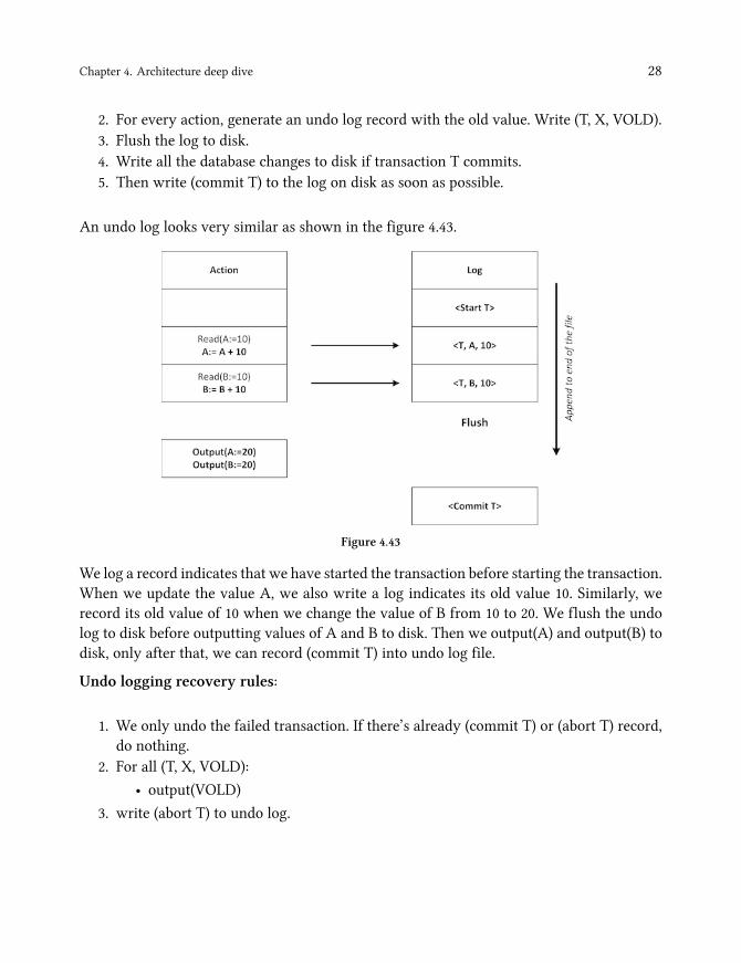
2. For every action, generate an undo log record with the old value. Write (T, X, VOLD).3. Flush the log to disk.4. Write all the database changes to disk if transaction T commits.5. Then write (commit T) to the log on disk as soon as possible.
An undo log looks very similar as shown in the figure 4.43.
Figure 4.43
We log a record indicates that we have started the transaction before starting the transaction.When we update the value A, we also write a log indicates its old value 10. Similarly, werecord its old value of 10 when we change the value of B from 10 to 20. We flush the undolog to disk before outputting values of A and B to disk. Then we output(A) and output(B) todisk, only after that, we can record (commit T) into undo log file.
Undo logging recovery rules:
1. We only undo the failed transaction. If there’s already (commit T) or (abort T) record,do nothing.
2. For all (T, X, VOLD):
• output(VOLD)
3. write (abort T) to undo log.

Chapter 4. Architecture deep dive 29
Figure 4.44
We read the undo log from the end to start, and looking for an incomplete transaction duringthe recovery process. Any records with (commit T) or (abort T) are ignored because we knowthat (commit T) or (abort T) can only be recorded after a successful output to disk. We cannotbe sure that output was successful if there are no (commit T) record, so for every record, weuse the old value VOLD to revert the changes. So, (T, B, 10) sets B back to 10 and so on. Undolog records (abort T) to indicate that we aborted the transaction after making the changes.
The main disadvantage of the undo log is that it might be slower for heavy write-intensiveapplication because for every transaction, we have to output the value to the disk beforerecords a (commit T) log in the undo log file.
At this moment, we can get back to our starting point about WAL. The second log approachfor protecting data-loss is the write-ahead log or WAL. Instead of undoing a change, WALtries to reproduce a change. During the transaction, we write all the changes to WAL that weare indented to do, so we can rerun transaction in case of disaster and reapplying the changesif necessary. Before making any output (write to the disk), we must record the (commit T)record.
WAL logging rules:
1. Record a log into undo file for every transaction T. Write (start T) to the log.2. Set its value to New if transaction modifies database record X. Write (T, X, Vⁿʷ) to the
log.3. Write (Commit T) to the log if transaction T commits.4. Flush the log file to the disk.
Chapter 4. Architecture deep dive 30
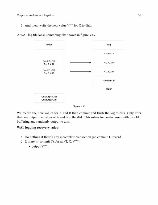
5. And then, write the new value Vⁿʷ for X to disk.
A WAL log file looks something like shown in figure 4.45.
Figure 4.45
We record the new values for A and B then commit and flush the log to disk. Only afterthat, we output the values of A and B to the disk. This solves two main issues with disk I/O:buffering and randomly output to disk.
WAL logging recovery rules:
1. Do nothing if there’s any incomplete transaction (no commit T) record.2. If there is (commit T), for all (T, X, Vⁿʷ):
• output(Vⁿʷ)

Chapter 4. Architecture deep dive 31
Figure 4.46
To recover with a WAL log file, we start from the beginning of the file scanning forwards(opposite of the undo log file). If we find any incomplete transaction (no commit T), weskip the transaction so that no output was done. We do not know whether the output wassuccessful or not whenever we find any (commit T) record. In this case, we redo the changes,and even it is redundant. In our example, the value of A will be set to 20, and the value of Bwill also be set to 20.
Now that we have got the basics of the log structure, so let’s move on to Ignite’sWAL conceptto see how the things organized under the cover. From the Ignite perspective, whenever thestorage engine wants to make any changes to the data page, it writes the change to the RAMand then appends the changes to the WAL. Storage engine sends an acknowledgment toconfirm the operation only after durably written the changes to WAL file on disk.

Chapter 4. Architecture deep dive 32
Figure 4.47
This makes the database changes reliably. If the node crashes while data was being appendedto the WAL, no problem because dirty data pages have not been copied from RAM to disk.So, storage engine can read and reply WAL using already saved page set if it crashes whilethe data pages are being modified. The storage engine can restore to state, which was lastcommitted state of the crashed process. In Ignite, restore is based on page store and WALlog. You may notice that Ignite native persistence is slightly different than the classical WALlog concept.
TipData changes are acknowledged only after the cache operations and page changeswere logged into the WAL. Dirty data pages will be copied later by anotherprocess.
Baseline topology
Ignite Baseline Topology or BLT represents a set of server nodes in the cluster that persistsdata on disk.

Chapter 4. Architecture deep dive 33
Where,
• N1-2 and N5 server nodes are the member of the Ignite cluster with native persistenceenable that persists data on disk.
• N3-4, N6 server nodes are the member of the Ignite cluster but not a part of the baselinetopology.
The nodes from the baseline topology are a regular server node, that store’s data in memoryand on the disk, and also participate in computing tasks. Ignite cluster can have differentnodes that are not a part of the baseline topology such as:
• Server nodes that are not used Ignite native persistence to persist data on disk. Usually,they store data in memory or persists data to a 3rd party database or NoSQL. In theabove equitation, node N3 or N4 might be one of them.
• Client nodes that are not stored shared data.
Let’s start at the beginning and try to understand its goal and which problem it’s solved toclear the baseline topology concept.
The database like Ignite is designed to support massive data storage and processing. Ignitedatabase are highly scalable and fault-tolerant. This high scalability feature of the Ignitebrings a few challenges for the database administrator, such as:
• how to manage a cluster?• How to add/remove nodes correctly? or• how to rebalance data after add/remove nodes?
Ignite cluster with a multitude of nodes can significantly increase the complexity of thedata infrastructure. Let’s look at it by the example of Apache Ignite. Ignite in-memorymodecluster concept is very simple. There are no master or dedicated node in the cluster, andevery node is equal. Each node stores a subset of data and can be participated in distributedcomputing or deploy any services. In case of any node failures, client requests served by theother nodes, and the data of the failed nodes will be no longer available. In this mode, Ignitecluster management operations are very similar as follows:

Chapter 4. Architecture deep dive 34
1. To run a cluster, start all nodes.2. To expand the cluster topology, add some nodes.3. To reduce the cluster topology, remove some nodes.
Data redistributes between nodes automatically. Data partitions moves from one node toanother depending on the backup copy configuration of the caches.
Figure 4.53
In the persistence mode, the node keeps their state even after the restart. Data is read fromthe disk and restores the node state during any read operation. Therefore, restart of a nodein persistence mode does not need to redistributed data from one node to another unlikein-memory mode. The data during node failure will be restored from the disk. This strategyopens up the opportunities to not only preventing ofmoving amassive amount of data duringnode failure but also reduce the startup times of the entire cluster after a restart. So, we needto distinguish somehow these nodes that can save their state after restart. In other words,the Ignite baseline topology provides this capability.

Chapter 4. Architecture deep dive 35
Figure 4.54
In a nutshell, Ignite baseline topology is a collection of nodes that have been configured forstoring persistence data on disk. Baseline topology tracks the history of the topology changesand prevents data discrepancies in the cluster during recovery. Let’s resume the goals of thebaseline topology:
1. Avoid redundant data rebalancing if a node is being rebooted.2. Automatically activate a cluster once all the nodes of the baseline topology have joined
after a cluster restart.3. Prevent the data inconsistencies in the case of split-brain.
Please note that, you can use persistence caches with the in-memory caches at the sametime. In-memory caches will live same as before: consider all nodes are equals and beginredistribution of the partitions whenever a node goes down. Baseline topology will takeaction only on the persistence caches. Hence, Ignite baseline topology has the followingcharacteristics:
Chapter 4. Architecture deep dive 36
1. Baseline topology defines a list of nodes which intended for storing data, and does notaffect other functionalities such as data grid, compute grid etc. If a new node joined tothe cluster where baseline topology is already defined, the data partitions is not startedmoving to the new node until the node is added to the baseline topology manually.
2. On each node, persistence Meta-data repository is used to store the history of thebaseline topology.
3. For a newly created cluster (or cluster without baseline topology), a baseline topologyis created for the first time during the first activation of the cluster. The administratormust explicitly do all the future changes (add/remove nodes) of the baseline topology.
4. If baseline topology is defined for a cluster, after restarting the cluster, the clusterwill be activated automatically whenever all the nodes from the baseline topology areconnected.
Now, let’s details how Ignite storage engine achieves the abovementioned goals.
Automatic cluster activation
A cluster can make on its own decision to activate the cluster in the persistence mode withbaseline topology. After the first activation of the cluster, the first baseline topology is createdand saved on the disk, which contains information about all nodes present in the cluster atthe time of activation. Each node checks the status of the other nodes within the baselinetopology after the cluster is rebooted. The cluster is activated automatically once all the nodesare online. This time the database administrator needs no manual intervention to activatethe cluster.
Chapter 4. Architecture deep dive 37
Figure 4.55
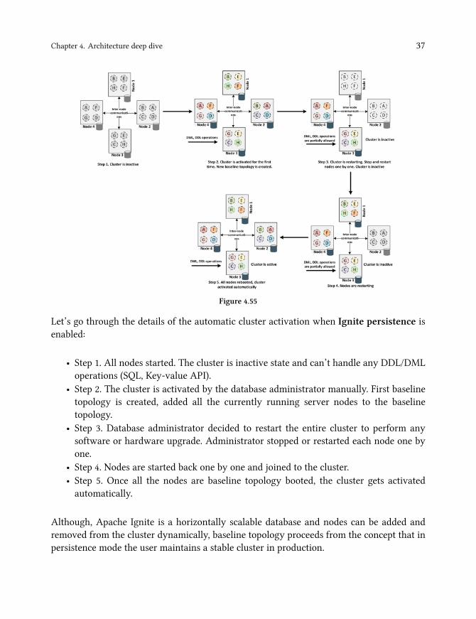
Let’s go through the details of the automatic cluster activation when Ignite persistence isenabled:
• Step 1. All nodes started. The cluster is inactive state and can’t handle any DDL/DMLoperations (SQL, Key-value API).
• Step 2. The cluster is activated by the database administrator manually. First baselinetopology is created, added all the currently running server nodes to the baselinetopology.
• Step 3. Database administrator decided to restart the entire cluster to perform anysoftware or hardware upgrade. Administrator stopped or restarted each node one byone.
• Step 4. Nodes are started back one by one and joined to the cluster.• Step 5. Once all the nodes are baseline topology booted, the cluster gets activatedautomatically.
Although, Apache Ignite is a horizontally scalable database and nodes can be added andremoved from the cluster dynamically, baseline topology proceeds from the concept that inpersistence mode the user maintains a stable cluster in production.
Chapter 4. Architecture deep dive 38
Split-brain protection
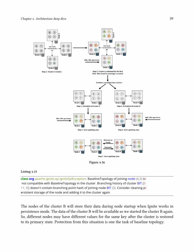
Split-brain¹⁶ is one of the common problems of distributed systems, in which a cluster ofnodes gets divided into smaller clusters of equal or nonequal numbers of nodes, each ofwhichbelieves it is only the active cluster. Commonly, the split-brain situation is created duringnetwork interruption or cluster reformation. The cluster reforms itself with the availablenodes when one or more node fails in a cluster. Sometimes instead of forming a singlecluster, multiple mini clusters with an equal or nonequal of nodes may be formed duringthis reformation. Moreover, these mini cluster starts handling request from the application,which makes the data inconsistency or corrupted. How it may happen is illustrated in figure4.56. Here’s how it works in more details.
• Step 1. All nodes started. The cluster is inactive state and can’t handle any DDL/DMLoperations (SQL, Key-value API).
• Step 2. The cluster is activated by the database administrator manually. First baselinetopology is created, added all the currently running server nodes to the baselinetopology.
• Step 3. Now let’s say, a network interruption has occurred. Database administratormanually split the entire cluster into two different clusters: cluster A and cluster B.Activated the cluster A with a new baseline topology.
• Step 4. Database administrator activated the cluster B with a new baseline topology.• Step 5-6. Cluster A and B are started getting updates from the application.• Step 7. After a while, the administrator resolved the network problem and decided tomerge the two different cluster into a single cluster. In this time baseline topology ofthe cluster A will reject the merge, and an exception will occur as follows:
¹⁶https://en.wikipedia.org/wiki/Split-brain_(computing)
Chapter 4. Architecture deep dive 39
Figure 4.56
Listing 4.15
class org.apache.ignite.spi.IgniteSpiException: BaselineTopology of joining node (4,3) is\not compatible with BaselineTopology in the cluster. Branching history of cluster BlT ([\11, 9]) doesn't contain branching point hash of joining node BlT (3). Consider cleaning p\ersistent storage of the node and adding it to the cluster again.
The nodes of the cluster B will store their data during node startup when Ignite works inpersistence mode. The data of the cluster B will be available as we started the cluster B again.So, different nodes may have different values for the same key after the cluster is restoredto its primary state. Protection from this situation is one the task of baseline topology.
Chapter 4. Architecture deep dive 40
As stated earlier, a new baseline topology is created and saved on the disk, which containsinformation about all the nodes presents in the cluster at the moment of activation whenwe activate the cluster first time. This information also includes a hash value based on theidentifiers of the online nodes. If some nodes are missing in the topology during subsequentactivation (for instance, the cluster was rebooted, and one node was removed permanentlyfor disk outage), the hash value is recalculated for each node, and the previous value is storedin the activation history within the same baseline topology. Such a way, baseline topologysupports a chain of hashes describing the cluster structure at the time of each activation.
In steps 3 and 4, the administrator manually activated the two incomplete cluster, and eachbaseline topology recalculated and updated the hash locally with a new hash. All nodes ofeach cluster will be able to calculate the same hashes, but they will be different in variousgroups. Cluster A determined that nodes of the cluster B is activated independently of thenode of the cluster A, and access was denied when the administrator tried to merge the twocluster into one. The logic is as follows:
Listing 4.16
if (!olderBaselineHistory.contains(newerBaselineHash))<join is rejected>
WarningPlease note that this validation does not provide full protection against split-brainconflicts. However, it protects against conflicts in case of administrative errors.
Fast rebalancing and it’s pitfalls
As described above, the rebalancing event occurs, and data starts moving between thenodes within the baseline topology whenever a new node joins or removes from thebaseline topology explicitly by the database administrator. Generally, rebalancing is a time-consuming process, and the process can take quite a while depending on the amount of thedata. In this section, we are going into details on the rebalancing process and its pitfalls.

Chapter 5. Intelligent cachingA cache is a high-speed data storage layer in front of the primary storage location whichstores a subset of data so that future requests for that data served up as fast as possible incomputer terminology. Primary storage could be any database or a file system that usuallystores data on non-volatile storage. Caching allows you to reuse previously retrieved orcomputed data efficiently, and it is one of the secrets of high-scalability and performance ofany enterprise level application.
You may wonder why we named the chapter intelligent caching! Because, from the lastdecades, the unbounded changes of the software architecture need not only correctly usedof a caching strategy but also properly configured (cache eviction, expiration) and sizingthe cache layer to achieve the maximum performance and high-scalability of an application.Caching can be used for speeding up requests on five main different layers or environmentsof your application architecture:
1. Client2. Network3. Web server4. Application5. Database
So, you should consider caching strategies for each layer of your application architecture toaccomplish the high-performance of an application, and implements it’s correctly. It shouldbe noted that none of the caching platforms or framework are a silver bullet. Cache usagesvary for different data sizes and scenarios. Firstly, you should measure the data sizes andrequests on each layer, doing various tests to find out the bottleneck and then with the wayof experiments you have to define a tool or framework for caching data before implementingany caching platform such as Ignite, Ehcache, Redis or Hazelcast on any application layer.
In this chapter, we want to focus primarily on things you need to know about data cachingand demonstrate the use of Apache Ignite for accelerating application performance withoutchanging any business logic code. So, we are going to cover the following topics throughoutthe entire chapter:
1. Different caching strategies and usage methods as a smart in-memory caching.

Chapter 5. Intelligent caching 42
2. Read/Write through and write behind strategies examples based on Hibernate andMyBatis for database caching.
3. Memoization or application level caching.4. Web session clustering.5. Moreover, a list of recommendations to correctly prepare the caching layer.

Chapter 5. Intelligent caching 43
Smart caching
I often hear suggestion like this when it comes to a matter of performance: Need for speed- Caching. However, I believe that in-memory caching is the last lines of defense when allcurrent optimization tricks reach a bottleneck. We have a lot of points for optimizing beforeconsidering a separate layer for caching data, such as:
• Optimizing SQL queries; runs a few SQL queries plans to define the bottleneck on thedatabase level.
• Adding necessary indexes on tables.• Optimizing and configuring connection pools on Application servers.• Optimizing application code, such as fetching data by paging.• Caching static data such as Java script, Images and CSS files on the Web server andthe client side.
Consider the regular N-Tier JEE architecture for optimizing and caching data as shown infigure 5.1.
Figure 5.1
Chapter 5. Intelligent caching 44
Caches can be applied and leveraged throughout the various layers of technology includingbrowsers, network layers (Content delivery network and DNS), web applications anddatabases as shown in figure 5.1. Cached information can include the result of databasequeries, computationally intensive calculation, API request/responses, andweb artifacts suchas HTML, JavaScript, and multi-media files. Therefore, for getting a high throughput of anentire application, you should consider optimization and caches on other layers, and not onlythe use of in-memory caching layer. These will give you the maximum benefits of cachingdata and improves the overall performance of the application.
Caching best practices
It’s essential to consider a few best practices for using cache smartly when implementinga cache on any application layer. A smart caching ensure that you implement all (or mostof them) the best practices whenever designing a cache. This subsection describes a fewconsiderations for using a cache
1. Decide when and which data to cache. Caching can improve performance; the moredata you can cache, the higher the chance to reduce the latency and contention that’sassociated with handling large volumes of concurrent requests in the original datastore. However, server resources are finite, and unfortunately, you could not cache allthe resources you want. Consider caching data that are read frequently but modifiedrarely.
2. The resilience of the caching layer. Your application can continue to operate by usingthe primary data storage if the cache is unavailable, and you won’t lose any criticalpiece of information.
3. Determine how to cache data effectively. Most often, caching is less useful fordynamic data. The key to using a cache successfully lies in determining the mostappropriate data to cache and caching it in the proper time. The data can be addedto the cache on demand the first time it is fetched from the store by the application.Subsequent access to this data can be satisfied by using this cache. On the other hand,you can upload the data into the cache during the application startup, and sometimesit’s called cache warm up.
4. Managing data expiration in caches. You can maintain a cache entry up-to-date byexpiring a cache entry into the cache. When a cached data expires, it’s removed fromthe cache, and a new cache entry will be added into the cache at the next time when itwill be fetched from the primary data. You can set a default expiration policy when youconfigure the cache. However, consider the expiration period for the cache carefully.Cache entry expires too quickly if you make it too short, and you will reduce the

Chapter 5. Intelligent caching 45
benefits of using the cache. On the other hand, you risk the data becoming stale if youmake the period too long. Additionally, you should also consider to configure the cacheeviction policy which will help you to evict cache entries from the cache whenever thecache is full and no more places exists to add a new entry.
5. Update the caches when data changes on the primary data store. Generally, amiddle-tier caching layer duplicates some data from the central database server. Itsgoal is to avoid redundant queries to the database. The cache entry has to be updated orinvalidated when the data updates in the database. You should consider the possibilityto maintain a cache entry as up-to-date as possible when designing a caching layer.Many database vendors allow getting a notification whenever any entity updates intothe database and updates the caches.
6. Invalidate data in a client-side cache. Data that is stored in a client-side cache(browser or any standalone application) is generally considered to be auspices of theservice that provides the data to the client. A service cannot directly force a client to addor remove information from a client-side cache. This means that it’s possible for a clientthat poorly configured the cache to continue using the staled information. However,a service that provides cache needs to ensure that each server response provides thecorrect HTTP header directives to instruct the browser on when and for how long thebrowser can cache the response.
Design patterns
There might be two different strategies in a distributed computing environment whencaching data:
• Local or private cache. The data is stored locally on the server that’s running an instanceof an application or service. Application performance is very high in this strategy,because, most often the cached data stored in the same JVM along with applicationlogic. However, when the cache is resident on the same node as the application utilizingit, scaling may affect the integrity of the cache. Additionally, when local caches areused, they only benefit the local application that consuming the data.
• Shared or distributed cache. The cache served as the common caching layer that canbe accessed from any application instances and architecture topology. cached data canspan multiple cache servers in this strategy, and be stored in a central location for thebenefit of all the consumers of the data. This is especially relevant in a system whereapplication nodes can be dynamically scaled in and out.

Chapter 5. Intelligent caching 46
TipWith the Apache Ignite you can implement either or both of the above strategieswhen caching data.
Basic terms
There are a few basic terms related to caching, frequently used throughout this book. Istrongly believe that you are already familiar with these terms. However, it will be usefulfor those who are not familiar with these terms and getting all the information in a singleplace.
Terms DescriptionCache entry A single cache value, consists of a key and its mapped data value within the
cache.Cache Hit When a data entry is requested from the cache, and the entry exists for the
given key. A more cache hit means that most of the requests are satisfied bythe cache.
Cache Miss When a data entry is requested from the cache, and the entry does not existsfor the given key.
Hot data Data that has recently been used by an application is very likely to bereassessed soon. Such data is considered hot. A cache may attempt to keep thehottest data most quickly available while trying to choose the least hot datafor eviction.
Cache eviction The removal of entries from the cache in order to make room for newerentries, typically when the cache has run out of data storage capacity.
Cache expiration The removal of entries from the cache after some amount of time has passed,typically as a strategy to avoid stale data in the cache.
Database caching
There are many challenges that disk-based databases (especially RDBMS) can pose to yourapplication when developing a distributed system that requires low latency and horizontalscaling. A few common challenges are as follows:
1. Expensive query processing. Database queries can be slow and require serious systemresources because the database system needs to perform some computation to fulfillthe query request.

Chapter 5. Intelligent caching 47
2. Database hotspots. It’s likely that a small subset of data such as a celebrity profile orpopular product (before Christmas) will be accessed more frequently than others inmany applications. The SQL queries on such favorite products can result in hot spotsin your database andmaybe overprovisioning of database resources (CPU, RAM) basedon the throughput requirements for the most frequently used data.
3. The cost to scale. Most often, RDBMS are only scaling vertically (anyway, Oracle 18c¹⁷and Postgres-XL¹⁸ can scaling horizontally but needs tremendous effort to configure).Scaling databases for extremely high reads can be costly and may require manydatabases read replicas to match the current business needs.
Most database servers are configured by default for optimal performance. However, eachdatabase vendors provides various optimizations tips and tricks to help engineers get themost out of their databases. These guidelines for database optimization observe a law similarto the funnel law that is illustrated in figure 5.2 and described below:
1. Reducing data access.2. Returning less data.3. Reducing interaction with the underlayer.4. Reducing CPU overhead and using more machine resources.
Figure 5.2
¹⁷https://www.oracle.com/technetwork/database/database-technologies/sharding/overview/index.html¹⁸https://www.postgres-xl.org

Chapter 5. Intelligent caching 48
Architects and engineers should make a great effort in squeezing as much performance asthey can out of their database as mentioned earlier, because database caching should beimplemented when all existing optimization tools reach a database bottleneck. A databasecache supplements your primary database by removing unnecessary pressure on it (veryclose to the reduce data access layer), typically in the form of frequently accessed read data.The cache itself can live in some areas including your database, application or as a standalonelayer.
The basic paradigm when querying data from a relational database from an applicationincludes executing SQL statement through ORM tools or JDBC API and iterating over thereturned ResultSet object cursor to retrieve the database rows. There are a few techniquesyou can apply based on your data access tools and patterns when wanting to cache thereturned data.
We are going to discuss how Ignite in-memory cache can be used as a 2ⁿ level cachesin different data access tools such as Hibernate and Mybatis in this section, which cansignificantly reduce the data access times of your application and improve overall applicationperformance.
A 2ⁿ level cache is a local or distributed data store of entity data managed by thepersistence provider to improve application performance.
A second level cache can improve application performance by avoiding expensive databasecalls, keeping the data bounded (locally available) to the application. A 2ⁿ level cache isfully managed by the persistence provider and typically transparent to the application. Thatis, application reads, writes and commits data through the entity manager without knowingabout the cache.
Figure 5.3
There is also a Level 1 cache based on the persistence provider, such asMyBatis or Hibernate.Level 1 is used to cache objects retrieved from the database within the current database

Chapter 5. Intelligent caching 49
session. An HTTP session is opened and reused until the service method returns when client-side (web page or web service) invokes a service. All operations performed until the servicemethod return will share the L1 cache, so the same object will not retrieve twice from thedatabase. Objects retrieved from the database will not be available after closing the databasesession.
TipIn most persistence providers, level 1 cache is always enabled by default.
So, in a nutshell, the 2ⁿ level cache provides the following benefits:
1. Boost performance by avoiding expensive database calls.2. Data are kept transparent to the application.3. CRUD operation can be performed through standard persistence manager functions.4. You can accelerate applications performance by using 2ⁿ level cache, without changing
the code.
Chapter 6. DatabaseStarting from version 2.0, Apache Ignite redesigned the storage engine and introduced anew memory-centric architecture that can be used as an In-memory database or a fullyfunctional distributed database with disk durability and strong consistency. Ignite memory-centric storage helps to store data and indexes both in-memory and on-disk in the same datastructure. It enables executing SQL queries over data stored in-memory and on-disk anddelivers optimal performance while minimizing infrastructure costs.
Apache Ignite data persistence on-disk mechanism is called Native persistence and is anoptional choice. When native persistence is turned on, Ignite can store more data than canfit in the available memory, and act like a complete distributed SQL database. On the otherhand, when the whole data set and indexes fit in memory, and the native persistence isdisabled, Ignite function as an in-memory database supporting SQL, together with all theexisting APIs for memory-only use cases.
Moreover, Apache Ignite supports Spring Data¹⁹ that allows abstracting an underlyingdata storage from the application layer since 2.0 version. Spring Data also allows usingout-of-the-box CRUD operations for accessing the database instead of writing boilerplatecode. Additionally, you can use Hibernate OGM²⁰ that provides JPA (Java Persistence API)supports for Ignite database.
How SQL queries works in Ignite
In this chapter so far, we have discussed a lot about Ignite SQL capabilities. Perhaps it is theexact time to dive deep into the Ignite distributed SQL engine to explorer how it runs SQLqueries under the hood. Most often Ignite executes SQL queries in two or more steps:
¹⁹https://spring.io/projects/spring-data²⁰http://hibernate.org/ogm/

Chapter 6. Database 51
• Ignite distributed SQL engine parse and analyze the DDL/DML statements, createsappropriate caches from a non-ANSI part of the SQL queries and delegates the ANSIpart to the H2 database engine.
• H2 executes a query locally on each node and passes a local result to the distributedIgnite SQL engine for aggregating the result or further processing.
Consequently, Apache Ignite SQL engine is firmly coupled with H2²¹ database and usesparticular version of the database (for instance, Ignite version 2.6 uses H2 1.4.195 version).Each Ignite node runs one instance of the H2 database in the embedded mode. In this mode,the H2 database instance runs within the same Ignite process as a in-memory database.
InfoH2 SQL engine always executes SQL queries on local Ignite node.
We have already introduced you to the H2 database in chapter 2. However, in this section,we are going to answer the following questions:
1. How tables and indexes organize in H2 database?2. How H2 database uses indexes?3. How to use SQL statements execution plans for optimizing queries?4. How SQL queries work for the PARTITIONED and REPLICATED caches?5. How concurrent modification works?
For simplicity, we use our well-known dataset: Employee and Department tables. We alsouse the Ignite SQLLINE command line tool and H2 Web console to run SQL queries.
H2 database supplies a web console server to access the local database using a web browser.As we described earlier, the H2 console server provides you to run SQL queries against theembedded node and check how the tables and indexes look like internally. Moreover, withthe H2 web console, you can analyze how a query is executed by the database, e.g., whetherindexes are used or if the database has done an expensive full scan. This feature is crucialfor optimizing the query performance. To do that, you have to start the Ignite local nodewith IGNITE_H2_DEBUG_CONSOLE system property or an environment variable set to true as shownbelow:
²¹http://www.h2database.com/html/main.html
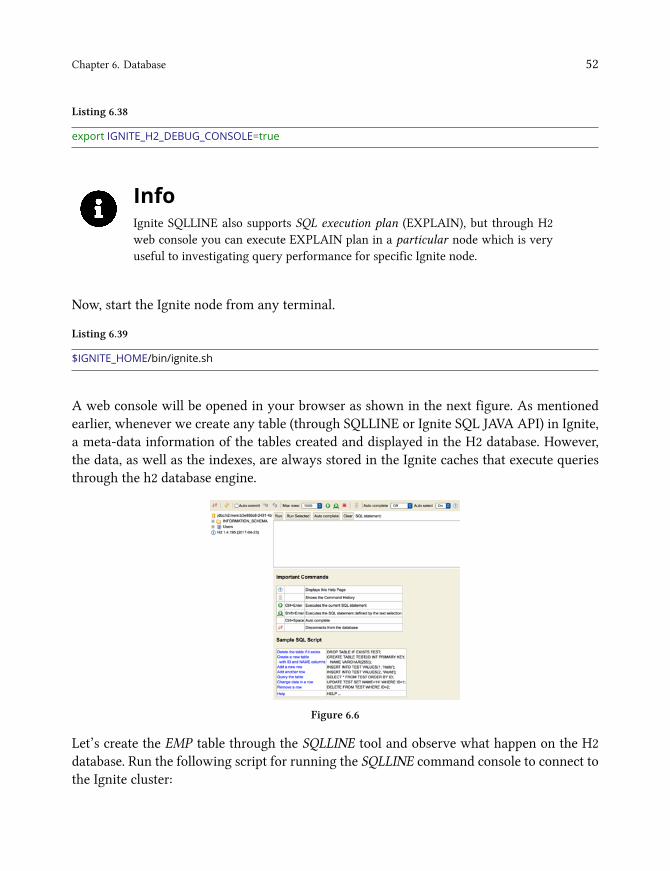
Chapter 6. Database 52
Listing 6.38
export IGNITE_H2_DEBUG_CONSOLE=true
InfoIgnite SQLLINE also supports SQL execution plan (EXPLAIN), but through H2web console you can execute EXPLAIN plan in a particular node which is veryuseful to investigating query performance for specific Ignite node.
Now, start the Ignite node from any terminal.
Listing 6.39
$IGNITE_HOME/bin/ignite.sh
A web console will be opened in your browser as shown in the next figure. As mentionedearlier, whenever we create any table (through SQLLINE or Ignite SQL JAVA API) in Ignite,a meta-data information of the tables created and displayed in the H2 database. However,the data, as well as the indexes, are always stored in the Ignite caches that execute queriesthrough the h2 database engine.
Figure 6.6
Let’s create the EMP table through the SQLLINE tool and observe what happen on the H2database. Run the following script for running the SQLLINE command console to connect tothe Ignite cluster:
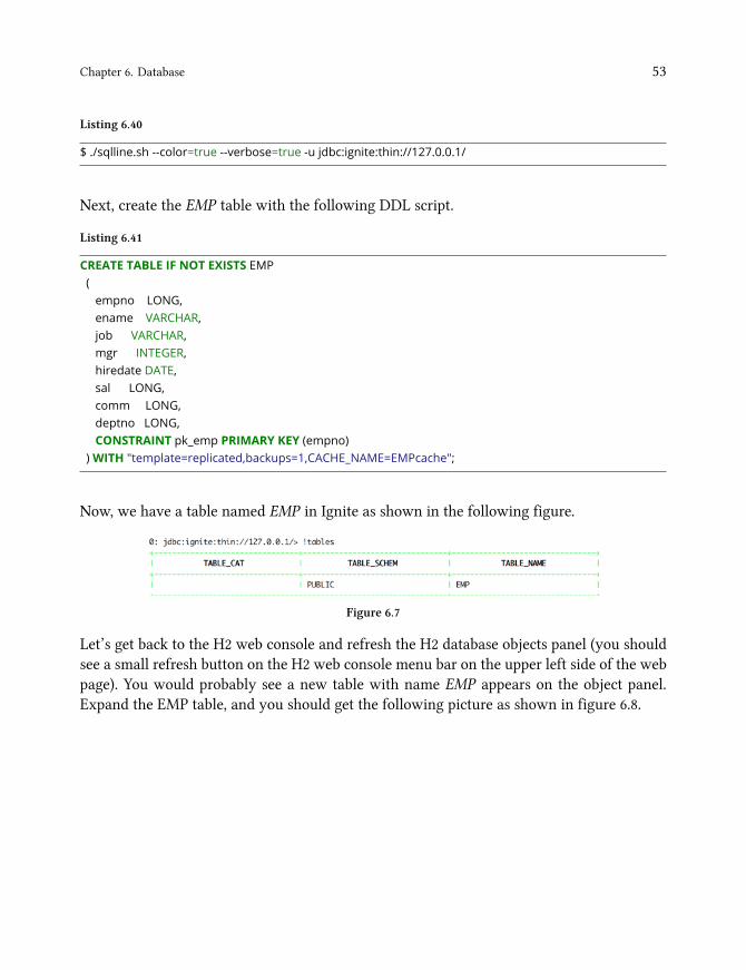
Chapter 6. Database 53
Listing 6.40
$ ./sqlline.sh --color=true --verbose=true -u jdbc:ignite:thin://127.0.0.1/
Next, create the EMP table with the following DDL script.
Listing 6.41
CREATE TABLE IF NOT EXISTS EMP(empno LONG,ename VARCHAR,job VARCHAR,mgr INTEGER,hiredate DATE,sal LONG,comm LONG,deptno LONG,CONSTRAINT pk_emp PRIMARY KEY (empno)
)WITH "template=replicated,backups=1,CACHE_NAME=EMPcache";
Now, we have a table named EMP in Ignite as shown in the following figure.
Figure 6.7
Let’s get back to the H2 web console and refresh the H2 database objects panel (you shouldsee a small refresh button on the H2 web console menu bar on the upper left side of the webpage). You would probably see a new table with name EMP appears on the object panel.Expand the EMP table, and you should get the following picture as shown in figure 6.8.
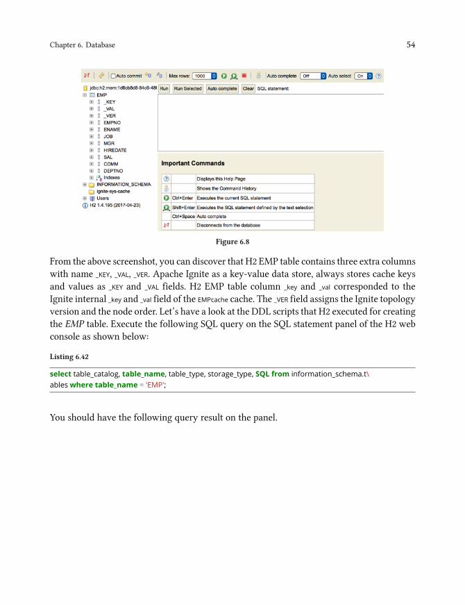
Chapter 6. Database 54
Figure 6.8
From the above screenshot, you can discover that H2 EMP table contains three extra columnswith name _KEY, _VAL, _VER. Apache Ignite as a key-value data store, always stores cache keysand values as _KEY and _VAL fields. H2 EMP table column _key and _val corresponded to theIgnite internal _key and _val field of the EMPcache cache. The _VER field assigns the Ignite topologyversion and the node order. Let’s have a look at the DDL scripts that H2 executed for creatingthe EMP table. Execute the following SQL query on the SQL statement panel of the H2 webconsole as shown below:
Listing 6.42
select table_catalog, table_name, table_type, storage_type, SQL from information_schema.t\ables where table_name = 'EMP';
You should have the following query result on the panel.

Chapter 6. Database 55
Figure 6.9
We used the H2 system table TABLES to get all the meta-data infotmation of the EMP table.
TipThe system tables of the H2 database in the schema INFORMATION_SCHEMA contain themetadata of all tables in the database as well as the current settings. Examples ofthe system tables are TABLES, INDEXES, VIEWS, etc.
The exciting part of the query result is STORAGE_TYPE, TABLE_CLASS and the SQL itself.
• SQL: See the listing 6.43. The CREATE table DDL statement indicates that the EMP table isa MEMORY table. A memory table is a persistence table, but the index of data is keptin the memory, so a memory table cannot be too large. The EMP table also uses customtable implementation which is specified by the ENGINE parameter. H2 uses the H2 tableengine implementation of the class org.apache.ignite.internal.processors.query.h2.H2TableEngine tocreate the EMP table. H2 table engine creates the table using given connection, DDLclause for given type descriptor and list of indexes. Created EMP table has threeindividual columns with invisible column definition which made the columns hidden,i.e., it will not appear in SELECT * results.
• TABLE_CLASS: org.apache.ignite.internal.processors.query.h2.opt.GridH2Table. The EMP table is notan H2 regular table. It’s a user-defined or custom designed table which is the typeof Ignite GridH2Table. The Ignite H2TableEngine uses the implementation of theGridH2Table for creating tables in the H2 database.
• STORAGE_TYPE: MEMORY. The storage type of the table is MEMORY.

Chapter 6. Database 56
Listing 6.43
CREATEMEMORY TABLE PUBLIC.EMP(_KEY BIGINT INVISIBLE NOT NULL,_VAL OTHER INVISIBLE ,_VER OTHER INVISIBLE ,EMPNO BIGINT,ENAME VARCHAR,JOB VARCHAR,MGR INT,HIREDATE DATE,SAL BIGINT,COMM BIGINT,DEPTNO BIGINT
)ENGINE "org.apache.ignite.internal.processors.query.h2.H2TableEngine"
Next, execute the following query into the H2 web console SQL statement pane.
Listing 6.44
select table_name, non_unique, index_name, column_name, primary_key, SQL, index_class fro\m information_schema.indexes where table_name = 'EMP';
We use the H2 system table INDEXES to discover the meta-data information about theindexes used by the EMP table. After executing the above SQL, you should have the followingoutput demonstrated in the next table.
TABLENAME
NONUNIQUE
INDEXNAME
COLUMNNAME
PRIMARYKEY
SQL INDEXCLASS
EMP FALSE _key_PK_hash _KEY TRUE CREATE
PRIMARY KEY
HASH
PUBLIC."_key_-
PK_hash" ON
PUBLIC.EMP(_-
KEY)
H2PkHashIndex
EMP FALSE _key_PK _KEY TRUE CREATE
PRIMARY KEY
PUBLIC."_key_-
PK" ON
PUBLIC.EMP(_-
KEY)
H2TreeIndex
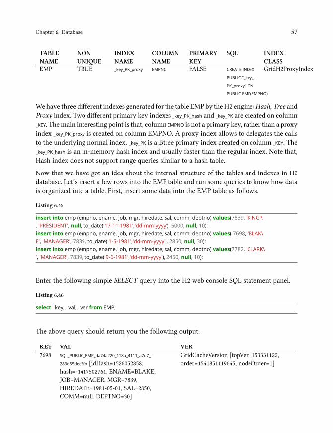
Chapter 6. Database 57
TABLENAME
NONUNIQUE
INDEXNAME
COLUMNNAME
PRIMARYKEY
SQL INDEXCLASS
EMP TRUE _key_PK_proxy EMPNO FALSE CREATE INDEX
PUBLIC."_key_-
PK_proxy" ON
PUBLIC.EMP(EMPNO)
GridH2ProxyIndex
Wehave three different indexes generated for the table EMP by theH2 engine:Hash, Tree andProxy index. Two different primary key indexes _key_PK_hash and _key_PK are created on column_KEY. Themain interesting point is that, column EMPNO is not a primary key, rather than a proxyindex _key_PK_proxy is created on column EMPNO. A proxy index allows to delegates the callsto the underlying normal index. _key_PK is a Btree primary index created on column _KEY. The_key_PK_hash is an in-memory hash index and usually faster than the regular index. Note that,Hash index does not support range queries similar to a hash table.
Now that we have got an idea about the internal structure of the tables and indexes in H2database. Let’s insert a few rows into the EMP table and run some queries to know how datais organized into a table. First, insert some data into the EMP table as follows.
Listing 6.45
insert into emp (empno, ename, job, mgr, hiredate, sal, comm, deptno) values(7839, 'KING'\, 'PRESIDENT', null, to_date('17-11-1981','dd-mm-yyyy'), 5000, null, 10);insert into emp (empno, ename, job, mgr, hiredate, sal, comm, deptno) values( 7698, 'BLAK\E', 'MANAGER', 7839, to_date('1-5-1981','dd-mm-yyyy'), 2850, null, 30);insert into emp (empno, ename, job, mgr, hiredate, sal, comm, deptno) values(7782, 'CLARK\', 'MANAGER', 7839, to_date('9-6-1981','dd-mm-yyyy'), 2450, null, 10);
Enter the following simple SELECT query into the H2 web console SQL statement panel.
Listing 6.46
select _key, _val, _ver from EMP;
The above query should return you the following output.
KEY VAL VER7698 SQL_PUBLIC_EMP_da74a220_118a_4111_a7d7_-
283d55dec3fb [idHash=1526052858,hash=-1417502761, ENAME=BLAKE,JOB=MANAGER, MGR=7839,HIREDATE=1981-05-01, SAL=2850,COMM=null, DEPTNO=30]
GridCacheVersion [topVer=153331122,order=1541851119645, nodeOrder=1]
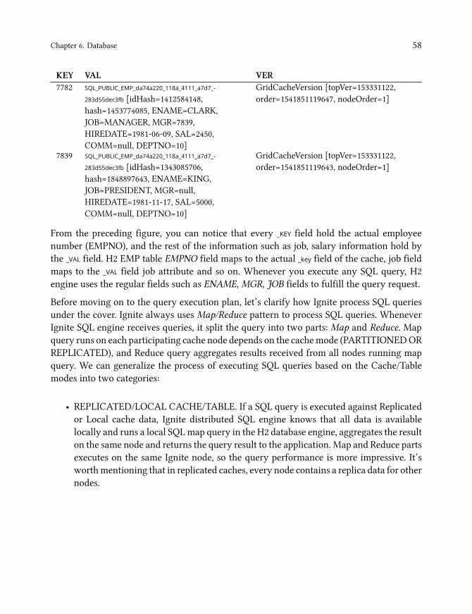
Chapter 6. Database 58
KEY VAL VER7782 SQL_PUBLIC_EMP_da74a220_118a_4111_a7d7_-
283d55dec3fb [idHash=1412584148,hash=1453774085, ENAME=CLARK,JOB=MANAGER, MGR=7839,HIREDATE=1981-06-09, SAL=2450,COMM=null, DEPTNO=10]
GridCacheVersion [topVer=153331122,order=1541851119647, nodeOrder=1]
7839 SQL_PUBLIC_EMP_da74a220_118a_4111_a7d7_-
283d55dec3fb [idHash=1343085706,hash=1848897643, ENAME=KING,JOB=PRESIDENT, MGR=null,HIREDATE=1981-11-17, SAL=5000,COMM=null, DEPTNO=10]
GridCacheVersion [topVer=153331122,order=1541851119643, nodeOrder=1]
From the preceding figure, you can notice that every _KEY field hold the actual employeenumber (EMPNO), and the rest of the information such as job, salary information hold bythe _VAL field. H2 EMP table EMPNO field maps to the actual _key field of the cache, job fieldmaps to the _VAL field job attribute and so on. Whenever you execute any SQL query, H2engine uses the regular fields such as ENAME, MGR, JOB fields to fulfill the query request.
Before moving on to the query execution plan, let’s clarify how Ignite process SQL queriesunder the cover. Ignite always uses Map/Reduce pattern to process SQL queries. WheneverIgnite SQL engine receives queries, it split the query into two parts: Map and Reduce. Mapquery runs on each participating cache node depends on the cachemode (PARTITIONEDORREPLICATED), and Reduce query aggregates results received from all nodes running mapquery. We can generalize the process of executing SQL queries based on the Cache/Tablemodes into two categories:
• REPLICATED/LOCAL CACHE/TABLE. If a SQL query is executed against Replicatedor Local cache data, Ignite distributed SQL engine knows that all data is availablelocally and runs a local SQLmap query in the H2 database engine, aggregates the resulton the same node and returns the query result to the application. Map and Reduce partsexecutes on the same Ignite node, so the query performance is more impressive. It’sworthmentioning that in replicated caches, every node contains a replica data for othernodes.
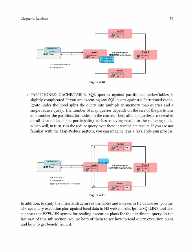
Chapter 6. Database 59
Figure 6.10
• PARTITIONED CACHE/TABLE. SQL queries against partitioned caches/tables isslightly complicated. If you are executing any SQL query against a Partitioned cache,Ignite under the hood splits the query into multiple in-memory map queries and asingle reduce query. The number of map queries depends on the size of the partitionsand number the partitions (or nodes) in the cluster. Then, all map queries are executedon all data nodes of the participating caches, relaying results to the reducing node,which will, in turn, run the reduce query over these intermediate results. If you are notfamiliar with the Map-Reduce pattern, you can imagine it as a Java Fork-join process.
Figure 6.11
In addition, to study the internal structure of the tables and indexes in H2 databases, you canalso see query execution plan against local data in H2 web console. Ignite SQLLINE tool alsosupports the EXPLAIN syntax for reading execution plans for the distributed query. In thelast part of this sub-section, we use both of them to see how to read query execution plansand how to get benefit from it.
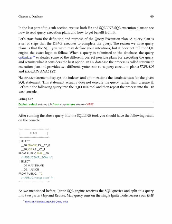
Chapter 6. Database 60
In the last part of this sub-section, we use both H2 and SQLLINE SQL execution plans to seehow to read query execution plans and how to get benefit from it.
Let’s start from the definition and purpose of the Query Execution plan. A query plan isa set of steps that the DBMS executes to complete the query. The reason we have queryplans is that the SQL you write may declare your intentions, but it does not tell the SQLengine the exact logic to follow. When a query is submitted to the database, the queryoptimizer²² evaluates some of the different, correct possible plans for executing the queryand returns what it considers the best option. In H2 database the process is called statementexecution plan and provides two different syntaxes to runs query execution plans: EXPLAINand EXPLAIN ANALYZE.
H2 EXPLAIN statement displays the indexes and optimizations the database uses for the givenSQL statement. This statement actually does not execute the query, rather than prepare it.Let’s run the following query into the SQLLINE tool and then repeat the process into the H2web console.
Listing 6.47
Explain select ename, job from emp where ename='KING';
After running the above query into the SQLLINE tool, you should have the following resulton the console.
+--------------------------------+| PLAN |+--------------------------------+| SELECT__Z0.ENAME AS __C0_0,__Z0.JOB AS __C0_1
FROM PUBLIC.EMP __Z0/* PUBLIC.EMP.__SCAN */|
| SELECT__C0_0 AS ENAME,__C0_1 AS JOB
FROM PUBLIC.__T0/* PUBLIC."merge_scan" */ |
+--------------------------------+
As we mentioned before, Ignite SQL engine receives the SQL queries and split this queryinto two parts:Map and Reduce. Map query runs on the single Ignite node because our EMP
²²https://en.wikipedia.org/wiki/Query_plan

Chapter 6. Database 61
table is replicated. Reduce query aggregate the result received from the H2 database in thesame node and return the result. So, in query execution plan we have two parts: Map partswith the Z0 prefix, and a reduce part with C0 prefix. If you run the above query through H2web console, you should have only one part as shown below. This is because, H2 executesthe entire queries as a whole and does not splits into parts.
SELECTENAME,JOB
FROM PUBLIC.EMP/* PUBLIC.EMP.__SCAN_ */
WHERE ENAME = 'KING'
Let’s get back to our explain plan result from the SQLLINE tool. Comment /*PUBLIC.EMP.__SCAN
*/ from theMap part of the query result indicates that the query does not use any indexes andexecutes a full table scan. These are the expected results because we did not create an indexon column ENAME. Let’s create a user-defined index on column ENAME through SQLLINEtool and re-run the explain plan query.
Listing 6.48
CREATE INDEX ename_idx ON emp (ename);
Now the SQL query to find the employee with name KING will use the index, and the explainplan query should return the following output.
+--------------------------------+| PLAN |+--------------------------------+| SELECT__Z0.ENAME AS __C0_0,__Z0.JOB AS __C0_1
FROM PUBLIC.EMP __Z0/* PUBLIC.ENAME_IDX: */|
| SELECT__C0_0 AS ENAME,__C0_1 AS JOB
FROM PUBLIC.__T0/* PUBLIC."merge_scan" */ |
+--------------------------------+
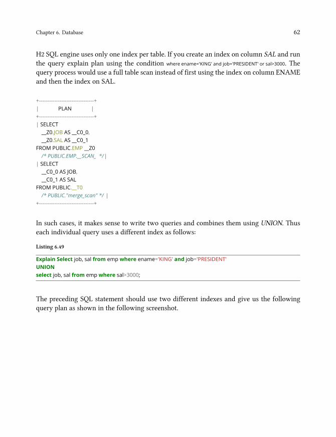
Chapter 6. Database 62
H2 SQL engine uses only one index per table. If you create an index on column SAL and runthe query explain plan using the condition where ename='KING' and job='PRESIDENT' or sal>3000. Thequery process would use a full table scan instead of first using the index on column ENAMEand then the index on SAL.
+--------------------------------+| PLAN |+--------------------------------+| SELECT__Z0.JOB AS __C0_0,__Z0.SAL AS __C0_1
FROM PUBLIC.EMP __Z0/* PUBLIC.EMP.__SCAN_ */|
| SELECT__C0_0 AS JOB,__C0_1 AS SAL
FROM PUBLIC.__T0/* PUBLIC."merge_scan" */ |
+--------------------------------+
In such cases, it makes sense to write two queries and combines them using UNION. Thuseach individual query uses a different index as follows:
Listing 6.49
Explain Select job, sal from emp where ename='KING' and job='PRESIDENT'UNIONselect job, sal from emp where sal>3000;
The preceding SQL statement should use two different indexes and give us the followingquery plan as shown in the following screenshot.

Chapter 6. Database 63
+--------------------------------+| PLAN |+--------------------------------+| SELECT__Z0.JOB AS __C0_0,__Z0.SAL AS __C0_1
FROM PUBLIC.EMP __Z0/* PUBLIC.ENAME_IDX: E */|
| SELECT__Z1.JOB AS __C1_0,__Z1.SAL AS __C1_1
FROM PUBLIC.EMP __Z1/* PUBLIC.IDX_SALARY: */|
| (SELECT__C0_0 AS JOB,__C0_1 AS SAL
FROM PUBLIC.__T0/* PUBLIC."merge_scan" */)
Besides to EXPLAIN keywords, you can also use ANALYZE keyword which shows thescanned rows per table. The EXPLAIN ANALYZE keyword actually executes the SQL queriesunlike EXPLAIN which only process it. This execution plan is useful to know how manyrows will be affected by the queries. Unfortunately, Ignite SQLLINE tool does not supportthe EXPLAIN ANALYZE keyword. However, you can use this keyword through H2 webconsole. The following query scanned two rows while executing the plan.
SELECTENAME,JOB
FROM PUBLIC.EMP/* PUBLIC.ENAME_IDX: ENAME = 'KING' *//* scanCount: 2 */
WHERE ENAME = 'KING'
WarningNot all execution plan is this simple and sometimes they might be challenging toread and understand.
HOW SQL join works. The internal of any query operation can be reviewed in the queryexecution plan. There are several factors that involves how the data is extracted and queriedfrom the source tables. Mainly there are two elements you need to be concerned about:

Chapter 6. Database 64
• Seeks and Scans. The first step to any query is to extract the data from the sourcetables. This is performed using one of two actions (and variations within): a seek or ascan. A seek is where the query engine can leverage an index to narrow down the dataretrieval. If no index is available, then the engine must perform a scan of all records inthe table. In general, seeks typically perform better than scans.
• Physical Joins. Once data is retrieved from the tables, it must be physically joined. Note,this is not the same as logical joins (INNER and OUTER). There are three physical joinoperators²³ that can be used by the engine: Hash Join,Merge Join and Nested loop join.
The query engine will evaluate several factors to determine which physical join will be themost efficient for the query execution. H2 uses hash joins during the query execution.
Another vital part of the query execution is the query optimizer. H2 SQL engine is a cost-based optimizer. Cost-based optimization involves generating multiple execution plans andselecting the lowest cost execution plans to fire and finally execute a query. The CPU, IO, andmemory are some of the parameters H2 uses in recognizing the cost, and finally generatingthe execution plan.
So, then you can better understand how the H2 database handles the SQL queries if youcan read and understand execution plans. It will help you to work on query tuning andoptimization. In other words, you will understand which objects are in use within thedatabase you are coding against. For more information, please visit the H2 database website.
Spring Data integration
When we develop an application which interacts with a database, we write a set of SQLqueries and bind them to the Java objects for saving and retrieving them. This standardapproach to persistence via Data Access Objects²⁴ is monotonous and contains a lot ofboilerplate code. Spring Data²⁵ simplifies this process of creating the data-driven applicationwith a new way to access data by removing the DAO implementations entirely.
²³https://www.periscopedata.com/blog/how-joins-work²⁴https://en.wikipedia.org/wiki/Data_access_object²⁵https://spring.io/projects/spring-data

Chapter 6. Database 65
In a nutshell, Spring Data provides a unified and easy way to access the different persistencestore, both relational database systems, and NoSQL data stores. It’s adding another layer ofabstraction and defining a standards-based design to support the persistence layer in a Springcontext. You do not have to write any more code for CRUD operations with Spring Data.Instead, you define an interface, Spring Data generates (no CGLib nor byte-code generation)the actual implementation on the fly for you.
Spring Data introduced the concept of Repository. It acts as an adapter, takes the domainclass to manage as well as the id type of the domain class as type arguments. This Repository
interface is the central interface in Spring data repository concept. The primary purpose ofthis interface is to capture the domain types to work, intercepts and routes all the calls to theappropriate implementation.
InfoNote that, Spring Data does not generate any code. Instead, a JDK proxy instanceis created programmatically using Spring’s ProxyFactory API to back the interface,and a MethodInterceptor intercepts all the method calls and delegates them to theappropriate implementations.
Spring data provides various interfaces (abstraction) that enable you to work or connectwith multiple data stores: CrudRepository, PagingAndSortingRepository. All of them extends the markerinterface Repository.
Chapter 8. Streaming and complexevent processingProbably you often heard the terms: Data-at-Rest and Data-in-Motion whenever talkingabout BigData management. Data-at-rest refers mostly at static data collected from one andmany data sources and followed by analysis. The Data-in-motion refers to a mode whereall the similar data collection method is applied, and data get analyzed at the same timeas it is generated. For instance, sensor data processing for the self-driving car from Google.Sometimes, this type of data is also called stream data. Analysis of a Data-in-motion is oftencalled Stream processing, Real-time analysis or Complex event processing.
Most often, Streaming data is generated continuously by thousands of data sources, whichtypically send in the data records simultaneously and in small sizes. Streaming data includesa wide variety and velocities of data such as log files generated by mobile devices, useractivities from e-commerce sites, financial trading floors or tracking information fromcar/bike sharing devices, etc.
This data needs to be processed sequentially and incrementally, and used for a wide varietyof analytics including aggregation, filtering or business intelligence for taking any businessdecision with latencies measured in microseconds rather than seconds of response time.Apache Ignite allows loading and processing of continuous never-ending streams of datain a scalable and fault-tolerant fashion, rather than analyzing data after it has reached thedatabase. This enables you to correlate relationships and detect meaningful patterns fromsignificantly more data that you can process it faster and much more efficiently.
Apache Ignite streaming and CEP can be employed in a wealth of industries area; thefollowing are some first-class use cases:
• Financial services: the ability to perform real-time risk analysis, monitoring ,andreporting of financial trading and fraud detection.
• Telecommunication: the ability to perform real-time call detail record, SMS monitor-ing ,and DDoS attack.
• IT systems and infrastructure: the ability to detect failed or unavailable applicationsor servers in real-time.
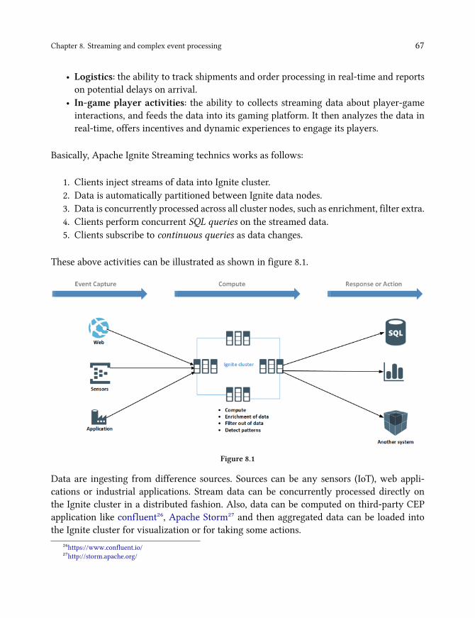
Chapter 8. Streaming and complex event processing 67
• Logistics: the ability to track shipments and order processing in real-time and reportson potential delays on arrival.
• In-game player activities: the ability to collects streaming data about player-gameinteractions, and feeds the data into its gaming platform. It then analyzes the data inreal-time, offers incentives and dynamic experiences to engage its players.
Basically, Apache Ignite Streaming technics works as follows:
1. Clients inject streams of data into Ignite cluster.2. Data is automatically partitioned between Ignite data nodes.3. Data is concurrently processed across all cluster nodes, such as enrichment, filter extra.4. Clients perform concurrent SQL queries on the streamed data.5. Clients subscribe to continuous queries as data changes.
These above activities can be illustrated as shown in figure 8.1.
Figure 8.1
Data are ingesting from difference sources. Sources can be any sensors (IoT), web appli-cations or industrial applications. Stream data can be concurrently processed directly onthe Ignite cluster in a distributed fashion. Also, data can be computed on third-party CEPapplication like confluent²⁶, Apache Storm²⁷ and then aggregated data can be loaded intothe Ignite cluster for visualization or for taking some actions.
²⁶https://www.confluent.io/²⁷http://storm.apache.org/

Chapter 8. Streaming and complex event processing 68
Apache Ignite provides native data streamers for loading and streaming large amounts ofdata into Ignite cluster. Data streamers are defined by IgniteDataStreamer API and are builtto ingest large amounts of endless stream data into Ignite caches. IgniteDataStreamer caningest data from various sources such as files, FTP, queues, etc., but the users must developthe adapter for connecting to the sources. Also, Ignite integrates with major streamingtechnologies such as Kafka, Camel, Storm or Flume to bring even more advanced streamingcapabilities to Ignite-based architectures. At themoment of writing this book, Ignite providesthe following data streamers for streaming a large amount of data into Ignite cluster:
• IgniteDataStreamer• JMS Streamer• Flume sink• MQTT Streamer• Camel Streamer• Kafka Streamer• Storm Streamer• Flink Streamer• ZeroMQ Streamer• RocketMQ Streamer
In practice, most developers use the 3ʳ party framework such as Kafka, Camel, etc. for initialloading and streaming data into Ignite cluster, because they are well known multi-purposetechnologies for complex event processing. So, in this chapter, first of all, we will introducethe Kafka streamer and then goes through the rest of the favorite data streamers, and providessome real-world running example for each streamer.

Chapter 8. Streaming and complex event processing 69
Kafka Streamer
Apache Ignite out-of-the-box provides Ignite-Kafka module with three different solutions(API) to achieve a robust data processing pipeline for streaming data from/to Kafka²⁸ topicsinto Apache Ignite.
Name DescriptionIgniteSinkConnector Consumes messages from Kafka topics and ingests them into an Ignite
node.KafkaStreamer Fetching data from Kafka topics and injecting them into Ignite node.IgniteSourceConnector Manages source tasks that listens to registered Ignite grid events and
forward them to Kafka topics.
IgniteSourceConnector
The Apache IgniteSourceConnector²⁹ is used to subscribe to Ignite cache events and streamthem to Kafka topic. In other words, it can be used to export data (changed datasets) froman Ignite cache into a Kafka topic. Ignite source connector listens to registered Ignite gridevents such as PUT and forward them to Kafka topic. This enables data that has been savedinto the Ignite cache to be easily turned into an event stream. Each event stream containskey and two values: old and new.
The IgniteSourceConnector can be used to support the following use cases:
1. To automatically notify any clients when a cache event occurs, for instance wheneverthere is a new entry into the cache.
2. To use an asynchronous event streaming from an Ignite cache to 1-N destinations. Thedestination can be any database or another Ignite cluster. These enable you to datareplication between two Ignite cluster through Kafka.
The Apache IgniteSourceConnector ships together with the IgniteSinkConnector, and avail-able in ignite-kafka-x.x.x.jar distribution. IgniteSourceConnector requires the following configu-ration parameters:
²⁸https://kafka.apache.org/²⁹https://ignite.apache.org/releases/latest/javadoc/org/apache/ignite/stream/kafka/connect/IgniteSourceConnector.html
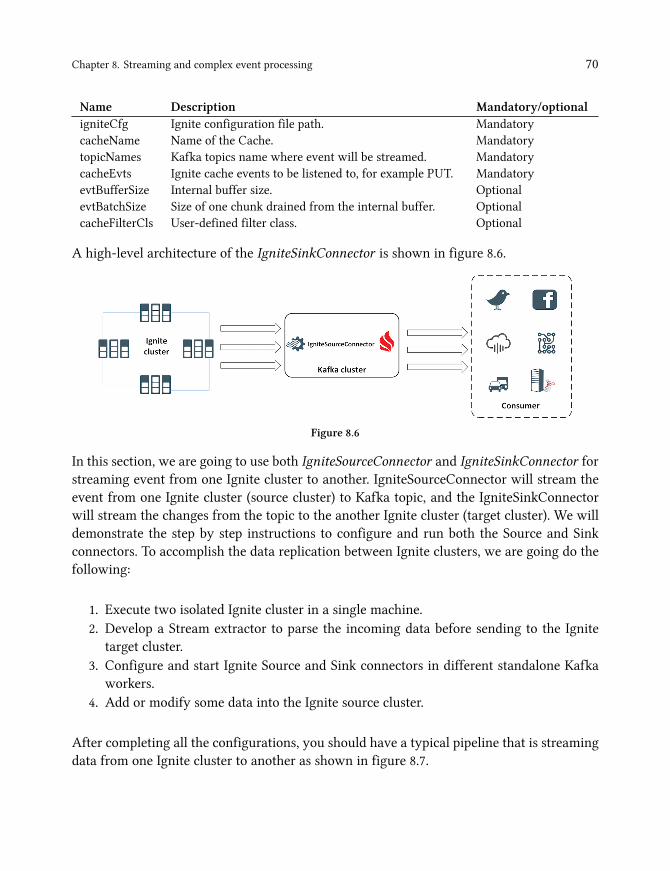
Chapter 8. Streaming and complex event processing 70
Name Description Mandatory/optionaligniteCfg Ignite configuration file path. MandatorycacheName Name of the Cache. MandatorytopicNames Kafka topics name where event will be streamed. MandatorycacheEvts Ignite cache events to be listened to, for example PUT. MandatoryevtBufferSize Internal buffer size. OptionalevtBatchSize Size of one chunk drained from the internal buffer. OptionalcacheFilterCls User-defined filter class. Optional
A high-level architecture of the IgniteSinkConnector is shown in figure 8.6.
Figure 8.6
In this section, we are going to use both IgniteSourceConnector and IgniteSinkConnector forstreaming event from one Ignite cluster to another. IgniteSourceConnector will stream theevent from one Ignite cluster (source cluster) to Kafka topic, and the IgniteSinkConnectorwill stream the changes from the topic to the another Ignite cluster (target cluster). We willdemonstrate the step by step instructions to configure and run both the Source and Sinkconnectors. To accomplish the data replication between Ignite clusters, we are going do thefollowing:
1. Execute two isolated Ignite cluster in a single machine.2. Develop a Stream extractor to parse the incoming data before sending to the Ignite
target cluster.3. Configure and start Ignite Source and Sink connectors in different standalone Kafka
workers.4. Add or modify some data into the Ignite source cluster.
After completing all the configurations, you should have a typical pipeline that is streamingdata from one Ignite cluster to another as shown in figure 8.7.

Chapter 8. Streaming and complex event processing 71
Figure 8.7
We will use the knowledge of Zookeeper and Kafka from the previous section to achieve thetask. Let’s start from the Ignite cluster configuration.
Step 1. We are going to start two isolated clusters on a single machine. To accomplish this, wehave to use a different set of TcpDiscoverySpi and TcpConfigurationSpi to separate the two clusterson a single host. So, for the nodes from the first cluster we proceed to use the followingTcpDiscoverySpi and TcpConfigurationSpi configurations:

Chapter 10. Management andmonitoringAs a system or cluster grows, you may start getting hardware or virtual machine failuresin your cloud/dedicated infrastructure. In such cases, you may need to do one of thesethings: add/remove nodes from the cluster or backup/repair nodes. These tasks come asan integral part of a system administrator daily work. Luckily all these tasks are relativelystraightforward in Apache Ignite and partially documented in Ignite documentation.
In the last chapter of this book, we will go through Ignite’s built-in and 3ʳ party toolsto manage and monitor the Ignite cluster in the production environment. We divided theentire chapter into two parts: management and monitoring. In the management part, wewill discuss different tools and technics to configure and manage the Ignite cluster. And wewill cover the basic of monitoring Apache Ignite includes logging, inspection of JVM, etc. inthe monitoring part.
Chapter 10. Management and monitoring 73
Managing Ignite cluster
Out-of-the-box Apache Ignite provides several tools for managing cluster. These toolsinclude web interface or command line interface that allows you to perform various tasksuch as start/stop/restart remote nodes or control cluster states (baseline topology). A tablebelow shows all the built-in tools of the Apache Ignite to configure and managing Ignitecluster.
Name DescriptionIgnite Web console Allows configuring all the cluster properties, and managing the Ignite
cluster through a web interface.Control script A command line script that allows to monitor and control cluster states
includes Ignite baseline topology.
InfoPlease note that Ignite Web console also uses for monitoring cluster functionalitylike cache metrics as well as CPU and Memory heap usages.
Monitoring Ignite cluster
At this point, your Ignite cluster is configured and running. Applications are using the Ignitecluster for writing and reading data to and from it. However, Ignite is not a set-it-and-forget-it system. Ignite is a JVM based system and designed to fast fail. So, it requires monitoringfor acting on time.
Ignite is built on JVM and JVM can use the JMX³⁰ or Java Management Extension. In otherwords, you can manage the system remotely by using JMX, gathering metrics (cache ormemory) including the memory, CPU, threads, or any other part of the system that hasbeen instrumented in JMX. Instrumentation enables the application or system to provideapplication-specific information to be collected by the external tools.
³⁰https://docs.oracle.com/javase/8/docs/technotes/guides/jmx/overview/intro.html

Chapter 10. Management and monitoring 74
InfoJMX was introduced in Java 5.0 release to manage & monitor the resources atruntime. Using JMX, we can monitor memory usage, garbage collection, loadedclasses, thread count, etc. over time.
MBeans or Managed Beans are a particular type of JavaBeans that takes a resource insidethe application or the JVM available externally. Figure 10.7 shows a high-level architectureof the JMX.
Figure 10.7
Apache Ignite provides a few JMXMBeans for collection and monitoring cache and memorymetrics as follows:
• CacheMetricsMXBean. MBean that provides access to cache descriptor.• CacheGroupMetricsMXBean. MBean that provides metrics for caches associated witha particular CacheGroup.
• DataRegionMetricsMXBean. MBean that provides access to DataRegionMetrics of alocal Apache Ignite node.
• DataStorageMetricsMXBean. An MBean allowing to monitor and tune persistencemetrics.
A few more new MBeans will be added in the subsequent Apache Ignite releases soon.
The standard tools that ships with Java for managing the MBeans is JConsole³¹ or Vi-sualVM³². In the case of VisualVM you have to install the VisualVM-MBeans plugin³³.
³¹https://docs.oracle.com/javase/7/docs/technotes/guides/management/jconsole.html³²https://docs.oracle.com/javase/8/docs/technotes/guides/visualvm/³³https://visualvm.github.io/plugins.html
Chapter 10. Management and monitoring 75
VisualVM is like JConsole but with more advanced monitoring featuring such as CPUprofiling and GC visualization.
TipIgnite allows running a VisualVM instance from IgniteVisor command. Use theignitevisor vvm command to open VisualVM for an Ignite node in the topology.
VisualVM
VisualVM is a GUI tool for monitor JVM. It helps the application developers and architectsto track memory leaks, analyze the heap data, monitor the JVM garbage collector and CPUprofiling. Moreover, after installing the VisualVM-MBeans plugin, you can manage andcollect metrics from JMX MBeans provides by the application. VisualVM can be also usedfor monitoring the local and the remote Java process as well.
As we stated before, for monitoring the Ignite process you can lunch VisualVM with twodifferent ways:
• Use ignitevisor VVM command to open a VisualVM instance or• lunch a VisualVM instance manually by the jVisualVM.exe|sh from the $JAVA_HOME/bin folder.
IgniteVisor VVM command under the cover uses the default JDK installation to run the localVisualVM tool. Let’s execute an Ignite node, create a table and populate some test data intothe table. I am going to use the EMP table and data from the previous section. If you arehaving any trouble to create the table, please refer to step 5 of the previous section.
Step 1. Lunch the VisualVM application from the JDK bin directory. On top-left corner ofthe application tab, you can see different options like Local, Remote and Snapshots. Selectthe org.apache.ignite.startup.cmdline.CommandLineStartup application from the Local section as shownbelow.

Chapter 10. Management and monitoring 76
Figure 10.8
By default when Ignite node is started with ignite.sh!bat script, it picks up a random JMX portand binds to it. You can explicitly set the JMX port by setting the IGNITE_JMX_PORT environmentalvariable. In *nix system it can be done in the following way:
export IGNITE_JMX_PORT=55555
However, if you run the Ignite node programmatically (i.e., by using Eclipse/IntelliJ IDEA),then the environmental variable IGNITE_JMX_PORT will not work. In such a situation, you needto pass the system parameters to your Java process that calls Ignition.start as follows:
-Dcom.sun.management.jmxremote -Dcom.sun.management.jmxremote.port={PREFERRED_PORT}-Dcom.sun.management.jmxremote.authenticate=false -Dcom.sun.management.jmxremote.ssl=fals\e
Step 2. The Memory, anf Threads tabs are sets of graphs that provide insight into the currentstate of the application. The monitor tab consists of graphs about the current state of theJava heap, CPU, Classes and threads (see Figure 10.8).

Chapter 10. Management and monitoring 77
Figure 10.9
The Classes graph is merely a graph of how many classes are loaded into the JVM at thecurrent time. One of the most important metrics to be aware of is your current heap usage.Ignite uses off-heap memory to store data from version 2.0 by default, so it is unnecessaryto use a large heap size for Ignite node. By using small heap size, you reduce the memoryfootprint on the system and possibly speed up the GC process.
Step 3. Let’s open the tab MBeans. There are many MBeans that are useful for assessingthe state of the Ignite node. You will notice that there are few grouping here that can beexpanded. All the Ignite MBeans classpath starts with the org.apache. Expand the groupCache Group under 18b4aac2 and click on the EMPcache MBean as shown in figure 10.10.
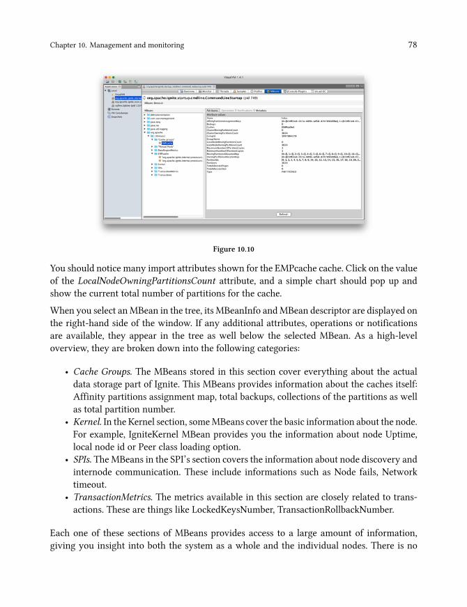
Chapter 10. Management and monitoring 78
Figure 10.10
You should notice many import attributes shown for the EMPcache cache. Click on the valueof the LocalNodeOwningPartitionsCount attribute, and a simple chart should pop up andshow the current total number of partitions for the cache.
When you select anMBean in the tree, its MBeanInfo andMBean descriptor are displayed onthe right-hand side of the window. If any additional attributes, operations or notificationsare available, they appear in the tree as well below the selected MBean. As a high-leveloverview, they are broken down into the following categories:
• Cache Groups. The MBeans stored in this section cover everything about the actualdata storage part of Ignite. This MBeans provides information about the caches itself:Affinity partitions assignment map, total backups, collections of the partitions as wellas total partition number.
• Kernel. In the Kernel section, someMBeans cover the basic information about the node.For example, IgniteKernel MBean provides you the information about node Uptime,local node id or Peer class loading option.
• SPIs. The MBeans in the SPI’s section covers the information about node discovery andinternode communication. These include informations such as Node fails, Networktimeout.
• TransactionMetrics. The metrics available in this section are closely related to trans-actions. These are things like LockedKeysNumber, TransactionRollbackNumber.
Each one of these sections of MBeans provides access to a large amount of information,giving you insight into both the system as a whole and the individual nodes. There is no

Chapter 10. Management and monitoring 79
need to cover all of them as you can easily explore them on your own using VisualVm GUIinterface.
Using JConsole/VisualVM to monitor a local application or Ignite node is useful fordevelopment or prototyping. Monitoring an Ignite cluster over 5 nodes by VisualVM orJConsole is unrealistic and time-consuming. Also, JMX does not provide any historicaldata. So, it is not recommended for production environments. Nowadays there is a lot oftools/software available for system monitoring. Most famous of them are:
• Nagios³⁴• Zabbix³⁵• Grafana, etc.
In the next sub-section, we cover the Grafana for monitoring Ignite node and provide step-by-step instructions to install and configure the entire stack technology.
Grafana
Grafana³⁶ is an open-source graphical tool dedicated to query, visualize and alert on forall your metrics. It brings your metrics together and lets you create graphs and dashboardsbased on data from various sources. Also, you can use Grafana to display data from differentmonitoring systems like Zabbix. It is lightweight, easy to install, easy configure, and it looksbeautiful.
Before we dive into the details, let’s discuss the concept of monitoring large-scale productionenvironments. Figure 10.11 illustrated a high-level overview of how the monitoring systemlooks like on production environments.
³⁴https://www.nagios.org³⁵https://www.zabbix.com³⁶https://grafana.com/grafana
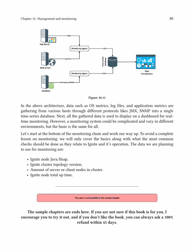
Chapter 10. Management and monitoring 80
Figure 10.11
In the above architecture, data such as OS metrics, log files, and application metrics aregathering from various hosts through different protocols likes JMX, SNMP into a singletime-series database. Next, all the gathered data is used to display on a dashboard for real-time monitoring. However, a monitoring system could be complicated and vary in differentenvironments, but the basic is the same for all.
Let’s start at the bottom of the monitoring chain and work our way up. To avoid a completelesson on monitoring, we will only cover the basics along with what the most commonchecks should be done as they relate to Ignite and it’s operation. The data we are planningto use for monitoring are:
• Ignite node Java Heap.• Ignite cluster topology version.• Amount of server or client nodes in cluster.• Ignite node total up time.
The sample chapters are ends here. If you are not sure if this book is for you, Iencourage you to try it out, and if you don’t like the book, you can always ask a 100%
refund within 45 days.