the astro line series - files.clrwtr.com · the astro line series ... around the concept that the...
TRANSCRIPT
THE ASTRO LINE SERIES
GEMINI 4000 INSTRUCTION MANUALPhone: 800.894.0412 - Fax: 888.723.4773 - Web: www.clrwtr.com - Email: [email protected]

INTRODUCTIONThe Gemini 4100 and 4200 are both units in a multi-purpose series of
industrial control units that are field-programmable to solve multipleapplications. This series, known as the Astro-Line family of products, is builtaround the concept that the end user has the capability to program differentpersonalities and functions into the unit in order to adapt to different indicationand control requirements.
The Gemini, which you have purchased, has the same high qualityworkmanship and advanced technological capabilities that have made Red LionControls the leader in today's industrial market.
Red Lion Controls has a complete line of industrial indication and controlequipment, and we look forward to being of service to you now and in the future.
CAUTION: Risk of Danger. Read complete instructions prior to
installation and operation of the unit.
CAUTION: Risk of electric shock.
Phone: 800.894.0412 - Fax: 888.723.4773 - Web: www.clrwtr.com - Email: [email protected]

TABLE OF CONTENTS
I. GENERAL DESCRIPTION 2A) Safety Summary 2B) Programming The Gemini 3C) Programming The Personality 3D) Programming The Presets, Scale Factors, Timed Outputs & Counter Load Values 3-5E) Initial Factory Configuration Counter/Rate & Dual Counter Factory Settings 6F) Operator Accessible Functions With Programming Disabled 7G) Diagnostics, Self-Test, & “Watchdog” Timer 7-8H) Input Circuitry & Set-up 8I) Overflow Indication 8
II. PROGRAMMING INSTRUCTIONS FOR THE COUNTER/RATE VERSION OF THE GEMINI 9A) Codes 41, 42, 43, 44, 45, & 46, 51, 52, 53, 54, 55, & 56 9-14B) Codes 61, 62, 63, 64, 65, 66, Preset Values, Scale Factors A & B, Counter Load Value 15-17C) Dual Preset Counter & Rate Application 18-19
III. PROGRAMMING INSTRUCTIONS FOR THE DUAL COUNTER VERSION OF THE GEMINI 20A) Codes 41, 42, 43, 44, 45, & 46 20-22B) Codes 51, 52, 53, 54, 55, & 56 22-25C) Codes 61, 64, 65, 66, Preset Values, Scale Factors A & B, Counter Load Values 25-27E) Dual Counter Batching Application 28-29
IV. 20 MA CURRENT LOOP COMMUNICATIONS 30A) Communication Format 30B) Sending Commands & Data To The Gemini 30-32C) Receiving Data From The Gemini 32D) Print Options 33E) Current Loop Installation 34F) Communications Application 35G) Troubleshooting Gemini Serial Communications & Serial Loop-Back Self-Test 36
V. APPENDIX “A” - INSTALLATION & INPUT CONFIGURATION SWITCH SET-UP 37-45VI. APPENDIX “B” - SPECIFICATIONS & DIMENSIONS 46-47VII. APPENDIX “C” - TROUBLESHOOTING GUIDE 48-49VIII. APPENDIX “D” - COUNTER/RATE & DUAL COUNTER MODE FUNCTION COMMAND CODE SUMMARY 50-57IX. APPENDIX “E” - SCALING FOR COUNTING 58-59X. APPENDIX “F” - SCALING FOR RATE 60-61XI. APPENDIX “G” - GEMINI 4100 PROGRAMMING CHARTS 62-64XII. APPENDIX “H” - GEMINI 4200 PROGRAMMING CHARTS 65-69XIII. APPENDIX “I” - ORDERING INFORMATION 70
Phone: 800.894.0412 - Fax: 888.723.4773 - Web: www.clrwtr.com - Email: [email protected]

GENERAL DESCRIPTIONThe Gemini 4000 series (4100 & 4200) instruments are two input
microprocessor based dual function counter/rate or dual counter instruments.The 6-digit display features 0.56" high LEDs with negative sign, overflow anddisplayed value indicators (A & B) located to the left of the display. Whenprogrammed as a counter/rate instrument, the A indicator will be on when the rateis displayed and the B indicator will be on when the count is being displayed.Pushing the “+/-” button toggles the display between the counter and rate or thetwo counters depending on the personality selected.
The Gemini 4000 series consists of two basic units, a single preset version, theGemini 4100, and a two preset version, the Gemini 4200. Each basic unit is alsoavailable in 115/230 VAC versions, with or without Serial communications and arelay board. The 20 mA current loop option (serial communications) makespossible remote or computerized monitoring or control of the Count, Presets andScale Factors.
Flexibility and usefulness are insured through user programmability. Withsimple front panel keystrokes and rear panel switch settings, any one of a numberof configurations can be selected. Once the selection is made, all or part of thekeyboard can be disabled to protect the settings and guarantee that no unwantedchanges can occur during the measurements.
Each time the power is turned off, the unit automatically saves the settings anddata in its special no power memory. When power is restored, the Gemini setsitself back to the operational modes and restores the data it had at power down.The “no power” E2PROM’s life expectancy is at least 100,000 cycles of powerbeing applied to and removed from the unit.
Whenever the power comes on, the Gemini performs a series of internaldiagnostics to verify the integrity of the stored data. There is also a self-test modeand a “watchdog” timer to help prevent processor lockup.
The Gemini 4000 series counters can accept bi-directional, uni-directional, orquadrature signals. They also have the capability to double or quadruple(Quadrature x4) the resolution of the incoming count signal. A separate inputmode is available to make the counter/rate or dual counters completelyindependent of each other.
One input provides the signal for rate or a counter and the other input providesthe signal for a counter. An anti-coincidence add/subtract mode is also providedto obtain a difference between two input signals.
Each channel features separate scaling and decimal point placement forreadout in different units or at different resolutions.
A Counter Load feature enables the operator to modify the count value undercircumstances that occur when flawed material has been counted and it isnecessary to adjust the count value accordingly. The Counter Load feature can be“locked out” in applications where it is not required.
The Rate Indicator portion uses a time interval method (1/tau) to calculate therate value. This method enables high resolution at all rates. The unit counts inputpulses and after a programmable minimum update time has occurred, it waitsuntil the next edge occurs, takes the elapsed time and number of edges, andcalculates the rate value. At slower rates, averaging can be accomplished byprogramming the “Rate Minimum Update Time” (0.5 sec. to 16 sec.) for thedesired response. Extensive scaling capabilities allow practically any desiredreading at very slow count rates.
For maximum flexibility, the Gemini’s output(s) can be assigned to either therate or count channels or one to each. When in dual counter mode, the output(s)can be assigned to the Counter B channel. For the Gemini 4200, one can beassigned to Counter A and the other to Counter B.
The relay(s) are mounted on a plug-in board which makes it easy to fieldupgrade your Gemini. The contacts are rated for 240 VAC or 28 VDC at 5 amps.
The construction of the Gemini features a metal, die cast bezel for maximumdurability with high quality appearance. The sealed front panel meets NEMA4/IP65 specifications for washdown and/or dust, when properly installed.Electrical connections are made with removable, plug-in terminal strips at therear of the unit. Clamp-type pressure plate terminals accept stripped #14 AWGwire without lugs.
SAFETY SUMMARY
All safety related regulations, local codes and instructions that appear in themanual or on equipment must be observed to ensure personal safety and toprevent damage to either the instrument or equipment connected to it. Ifequipment is used in a manner not specified by the manufacturer, the protectionprovided by the equipment may be impaired.
Do not use this unit to directly command motors, valves, or other actuators notequipped with safeguards. To do so, can be potentially harmful to persons orequipment in the event of a fault to the unit.
Phone: 800.894.0412 - Fax: 888.723.4773 - Web: www.clrwtr.com - Email: [email protected]

PROGRAMMING THE GEMINI
When your Gemini arrives from the factory, it has already been programmedto function as a counter and rate indicator. It is programmed with the factorysettings listed in the “Initial Factory Configuration” section. If it is required tohave the unit operate as two counters, the Unit Personality function code can bechanged to do so.
The personality, functions, and modes are accessed by pressing the appropriatekeys. A function is defined by a two-digit code which appears on the left side of thedisplay. The mode of that function is shown as a one-digit code on the right side ofthe display. At times there will be a “-” sign modifier to the left of the mode.
Data for the Presets, Scale Factors, Timed Output Values, and Counter LoadValues are entered differently. Each digit key controls the digit on the displaydirectly above it. Changing the digits can be done by repeatedly pressing the keybeneath the digit position you wish to change or by holding the key down. As youhold it down, or repetitively press it, the value of that digit will change cyclically,counting up to 9, then to 0, and then up again. The 6 numbered keys correspond tothe six digits, and the “+/-” key corresponds to polarity.
PROGRAMMING THE PERSONALITY
Entering function and mode is easily accomplished bypressing the appropriate digit key. For the personality function,you would enter 41 by pressing the front panel keys 4 and 1.
The digits on the left side of the display show the functioncode; the digits on the right side show the currentprogrammed mode.
A mode selection is made by entering a new number. Onsome of the entries, you have the option of a plus “+” or minus“-” sign. In the cases where a “+” sign is required, no sign willbe displayed. If you do enter a “-” sign (using the “+/-” key), aminus sign will be displayed in front of the appropriate digit.
Pressing the “E” key finalizes the change. The displaywill now show the count or rate value immediately.
If you do not press the “E” key, the change will not berecorded. The display will remain in the programming modefor 15 seconds, and then return to normal operating modeusing the old functional mode setting.
Whenever the Unit Personality is changed, the factory settings willautomatically be loaded into the unit. The factory settings can also beprogrammed into the unit by calling up the Unit Personality, putting a “-” in frontof the mode by pushing the “+/-” button, and entering it.
Refer to the “Initial Factory Configuration” section for more details.
PROGRAMMING THE PRESET, SCALE FACTORS, TIMEDOUTPUTS & COUNTER LOAD VALUES
The Presets and Scale Factor Values are commonly reprogrammed on a dailybasis. As such, single keystroke access has been provided.
The Gemini has two Scale Factors, one for display A(Counter A or Rate A), and one for display B (Counter B).Pressing the “3” key will call up the Scale Factor for thecurrent display (Rate A/Counter A, or Counter B).
To call up the “other” Scale Factor, the “+/-” key is first pushed to change thedisplay to the “other” value, then the “3” key is pushed to display the Scale Factorfor that value.
Phone: 800.894.0412 - Fax: 888.723.4773 - Web: www.clrwtr.com - Email: [email protected]

PROGRAMMING THE PRESET, SCALE FACTORS, TIMEDOUTPUTS & COUNTER LOAD VALUES (Cont’d)
Once the Scale Factor is displayed, changing the digitscan be accomplished by repeatedly pressing the key beneaththe digit position you wish to change or by holding the keydown, allowing the digit to cycle.
The new value will be entered when the “E” key ispressed.
The internal count value is multiplied by the Scale Factor Value, whichchanges the displayed value accordingly. It is important to note that the precisionof an application cannot be improved by using a Scale Factor greater than one. Toaccomplish greater precision, more pulse information must be generated permeasuring unit. For example, if 5 pulses are being received per foot of material,the precision of 10th of feet cannot be attained by simply programming a ScaleFactor of 2.0000, even though the display is reading in tenths. In this case, thedisplay will increment by two for each count input. Thus, if an odd Preset Valueis entered, such as 6.7 ft., the Gemini will alter the Preset display to read in eventenths of feet.
To display the Preset 1 Value the “1” key is pushed.
To change the value, the digits can be cycled through inthe same manner as discussed for the Scale Factor. Thepreset values can range from -999999 to +999999.
The new value will be entered when the “E” key ispressed.
The Scale Factor Value will have a direct effect on the preset being entered (ifassigned to the counter). For Scale Factors greater than one, the preset valueshould be an integer multiple of the Scale Factor. If it is not, the Gemini willautomatically adjust the preset value up or down to force it to be evenly divisibleby the Scale Factor.
The Timed Output 1 or 2 Value is changed by entering atwo-digit function code. After the code is entered, thedisplay will show the present Timed Output Value inseconds with two decimal place resolution. The TimedOutput Values can be set from .01 to 599.99 seconds.
To change the Timed Output 1 Value, enter function code53 and enter the new value by holding down or repeatedlypressing the key below the digit position you wish to change.The new value will be entered when the “E” key is pressed.The display will immediately return to the count value.
Note: A Timed Output Value of zero cannot be programmed into the Gemini. If avalue of 0 is entered into the display and the “E” key is pressed, the unit willremain in data entry mode. If a new value is not entered, it will time out and theunit will continue to use its previous setting.
As with the other functions, you must press “E” to record the changes. For thedata entry modes, if you do not press the “E” key, a time out of 5 seconds occurs,and the display returns to operating mode without any changes to the value. Theonly time any change will occur is when the “E” key is pressed.
Phone: 800.894.0412 - Fax: 888.723.4773 - Web: www.clrwtr.com - Email: [email protected]

It is possible to change the counter values of the Gemini. This feature can beenabled or disabled by the programming of the “Operator Accessible FunctionsModes”, function code 66. The “Counter Load Value” is not stored when the unitis powered down. When the unit is powered up, the Counter Load values for bothcounters (if Dual counter personality) are reset to zero. Once changed, the valueswill be held until the unit is again powered down.
To access the Counter Load value for the desired counter;first, press the “+/-” key, if necessary, so that the display isindicating the counter value which is to be changed.
Secondly, press the “E” key and while holding it down,press the “+/-” key.
The Gemini will now display the displayed Counter Loadvalue. (It will be zero, unless the value had been changedsince the unit was powered up.)
To change the value, press the key under the digit to bechanged as explained previously for the Preset.
To load the value into the counter, press the “E” key.The display will flash momentarily and will display the
counter with the new value.
Phone: 800.894.0412 - Fax: 888.723.4773 - Web: www.clrwtr.com - Email: [email protected]

INITIAL FACTORY CONFIGURATION DUAL COUNTER FACTORY SETTINGS*
Keys struck Display Description
4,1 41 2 Personality selected as DUAL COUNTER
4,2 42 3 Reset Counters A & B
4,3 43 1 Count with Inhibit
4,4 44 1 Single edge counting (A & B)
4,5 45 1 Counter B Scale multiplier of 1.0
4,6 46 1 Counter B leading zero blanking and no decimal point
5,1 51 2 Outputs 1 & 2 assigned to Counter B
5,2 52 3 Output 1 terminates at Reset, Normal Phase.
5,3 0000.10 Timed Output 1 Value of 0.1 Sec
5,4 54 3 Output 2 terminates at Reset, Normal Phase.
5,5 0000.10 Timed Output 2 Value of 0.1 Sec
5,6 56 1 Counter B, manual reset to zero
6,1 61 1 Counter A, manual reset to zero
6,4 64 1 Counter A scale multiplier of 1
6,5 65 1 Counter A leading zero blanking, no decimal point
6,6 66 1 No functions except Reset enabled
3 01.0000 Scale Factor A set to 1.0000
3 01.0000 Scale Factor B set to 1.0000
1 000500 Preset 1 set to 500
2 001000 Preset 2 set to 1000
* If [41 1] is changed to [41 2], then the factory settings are as shown.
Keys struck Display Description
4,1 41 1 Personality selected as COUNTER/RATE
4,2 42 3 Reset Rate (A) Output(s) & Counter (B)
4,3 43 1 Count with Inhibit
4,4 44 1 Single edge counting (B)
4,5 45 1 Counter B Scale multiplier of 1.0
4,6 46 1 Counter B leading zero blanking and no decimal point
5,1 51 2 Outputs 1 & 2 assigned to Counter (B)
5,2 52 3 Output 1 terminates at Reset, Normal Phase
5,3 0000.10 Timed Output 1 Value of 0.1 Sec
5,4 54 3 Output 2 terminates at Reset, Normal Phase
5,5 0000.10 Timed Output 2 Value of 0.1 Sec
5,6 56 1 Counter (B), manual reset to zero
6,1 61 4 No Rate (A) right hand dummy zeros
6,2 62 1 Rate per Second
6,3 63 1 Rate (A) 0.5 Sec Minimum Update Time
6,4 64 4 Rate (A) Scale multiplier of 1
6,5 65 1 Rate (A) leading zero blanking, no decimal point
6,6 66 1 No functions except Reset enabled
3 01.0000 Scale Factor A (Rate) set to 1.0000
3 01.0000 Scale Factor B (Counter) set to 1.0000
1 000500 Preset 1 set to 500
2 001000 Preset 2 set to 1000
Phone: 800.894.0412 - Fax: 888.723.4773 - Web: www.clrwtr.com - Email: [email protected]

OPERATOR ACCESSIBLE FUNCTIONS WITHPROGRAMMING DISABLED
(For details on keyboard entry, see preceding section)
One of the important features of the Gemini is the ability to disableprogramming. With this ability, accidental bumping of the keys or tampering byunauthorized personnel can be prevented. However, it may be necessary to allowreset and certain programming functions, such as Preset and Scale Factor Values,to be changed in daily operation. The Gemini, through the use of the “OperatorAccessible Functions” Modes can enable these functions even when the “PGM.DIS.” (Program Disable) terminal is connected to “COMMON”.
The “Operator Accessible Functions” modes are programmed by entering atwo-digit function code (66) and the desired mode. Unlike other function codes,the mode does not take effect immediately. The “PGM. DIS.” terminal must beconnected to “COMMON” in order for the Gemini to disable programming andoperate as per the mode programmed.
There are six basic “Operator Accessible Functions” Modes available. Thesemodes enable the following functions.
1. NO FUNCTIONS EXCEPT RESET ENABLED - In this mode, manualreset is enabled, but none of the programming functions can be changed.However, the functions can be interrogated.
2. PRESET PROGRAMMING AND RESET ENABLED - The entire frontpanel is disabled with the exceptions of Preset programmability and manualreset. All functions can be interrogated.
3. SCALE FACTOR PROGRAMMING AND RESET ENABLED - Theentire front panel is disabled with the exceptions of Scale Factorprogrammability and manual reset. All functions can be interrogated.
4. SCALE FACTOR AND PRESET PROGRAMMING, AND RESET
ENABLED - The entire front panel is disabled with the exceptions of ScaleFactor and Preset programmability, and manual reset. All functions can beinterrogated.
5. PRESET AND COUNTER LOAD PROGRAMMING, AND RESET
ENABLED - The entire front panel is disabled with the exceptions of Presetand Counter Load programmability. All functions can be interrogated.
6. PRESET, SCALE FACTOR AND COUNTER LOAD PROGRAMMING,
AND RESET ENABLED - The entire front panel is disabled with theexceptions of Preset, Scale Factor and Counter Load programmability. Allfunctions can be interrogated.
All of these modes can be modified with the addition of a “-” sign. The minussign disables the manual reset, at the front panel and the remote reset (RST., notRST.A) terminal, at the rear of the unit.
There is also a rear panel DIP switch which permits disabling of the front panelreset button. This is independent of the rear terminal remote reset, and can beused in conjunction with any front panel disable mode. The combination of amanual and remote reset inputs provides a high level of security withoutsacrificing flexibility.
DIAGNOSTICS, SELF-TEST, & “WATCHDOG” TIMER
The security of the Gemini is further enhanced by its self-test diagnostic and“watchdog” timer capabilities.
The diagnostics are concerned with the special, no power memory of theGemini. Whenever the power is turned off, all pertinent function settings andmeasurements (except the Counter Load values) are automatically saved. Whenpower is restored, the functions and data are re-instated. This allows you toprogram the unit once and not have to re-program it until you wish to use it inanother mode.
When the function codes and data are saved, computations are made withthese values. The result of these computations is stored in the memory to serve asa check against possible error. On power up the same computations are repeatedon the stored data. If the results do not agree with the stored results, a “P” willappear on the left side of the display. If this occurs, refer to the “TroubleshootingGuide” for directions.
Phone: 800.894.0412 - Fax: 888.723.4773 - Web: www.clrwtr.com - Email: [email protected]

DIAGNOSTICS, SELF-TEST, & “WATCHDOG” TIMER [Cont’d]
Another error indicator is the “watchdog” timer. In order to insure thesoftware is functioning properly, the program constantly monitors itself. If theproper sequence and timing of internal events does not occur, an “E” will appearon the left side of the display. If this occurs, refer to the “Troubleshooting Guide”for directions.
The final type of built-in error checking is the front panel initiated self-test. Itcan be performed at any time, even when the Gemini is running. It will notinterfere with the accumulation of counts or control functions. A function code of“6”, “+/-” starts the test. At this time, whatever was displayed will disappear andbe replaced by a string of decimal points and the overflow indicator. Then thedisplay will show a string of 9’s, then 8’s etc., until a string of 0’s are shown. Theself-test will then turn off the overflow indicator and activate the minus “-” sign.Then the unit shows an interlace pattern of -010101, then -212121, followed by232323 etc., until -898989 is reached. At this time the outputs can be tested bypressing the “1” or “2” key. (The program disable terminal must be disconnectedin order to allow activation of the outputs. Also, when testing the output, usecaution, so as not to cause any undesirable or hazardous conditions in thesystem.) An automatic exit will take place after six seconds or immediately if theProgram Disable terminal is connected to common. Normal length of displaytime for each of the patterns is approximately 0.5 sec. Rapidly pressing “E”during self-test can speed up the sequence.
INPUT CIRCUITRY & SET-UP
There are two independent input channels on the Gemini. Various types ofsensor outputs can be accommodated by appropriate DIP switch set-up. Theseinclude: TTL or CMOS logic, current sinking, current sourcing, or dry contactand more.
Channel 1 consists of a logic input and a separate low level magnetic pickupinput.
Channel 2 is a completely independent count or control input channel. LikeChannel 1, it can be programmed with DIP switches for a wide variety of logicinputs, and is identical to Channel 1 in this regard. For a complete detaileddescription of input set-up, see Appendix “A”.
OVERFLOW INDICATION
The Gemini features an overflow indicator (LED) which is located to the leftof the sixth digit and above the polarity annunciator. This LED will turn on if thecapacity of the display (6-digits) is exceeded or if the internal count capacity(9-digits) is exceeded. Use of extremely small scale multiplier and Scale FactorValues can cause the internal count capacity to overflow before the displayedvalue would overflow. It should also be noted that the use of Right Hand DummyZeros or Scale Factors larger than one could cause the displayed value tooverflow before a value of 999,999 (6-digits) is accumulated.
When the capacity of the display is exceeded, the count value will bemaintained and will be valid. But if the internal count value is exceeded, then thisvalue may no longer be valid.
The overflow LED can also turn on under certain conditions when the rateinput frequency exceeds the maximum 3250 cps allowed for a rate update periodof 16 sec. See Code 63 - “Rate Minimum Update Time”.
Phone: 800.894.0412 - Fax: 888.723.4773 - Web: www.clrwtr.com - Email: [email protected]

PROGRAMMING INSTRUCTIONS FOR THE COUNTER/RATE VERSION OF THE GEMINI 4000
The first part of this section provides detailed descriptions of the functioncommand codes for inputs response modes, reset modes, output terminations,etc. Then, using an actual application example, the programming instructions fora Counter/Rate version will be “walked through”, to give the user a fullunderstanding of the Gemini programming procedure. The descriptions belowgive the function command code first, followed by the individual modeidentifier. The Function Command Code Summary in the appendix, lists allcodes. (Only commands and modes pertaining to the Counter/Rate personalitywill be discussed in this section.)
CODE 41 - UNIT PERSONALITY
The Gemini can be programmed to operate in one of two differentpersonalities. In each of the two unit personalities, the Gemini operates as a dualfunction indicator. The personality selected determines whether display channelA will indicate rate or count. In both personalities, display channel B operates asa counter.
When the Unit Personality is changed and entered, all modes and data values(Preset, Scale Factors, function codes etc.) will be automatically loaded with thefactory settings for that personality. If, for any reason during programming, it isdesired to return to the factory settings (while in code 41), the “+/-” key can bepushed. When the “E” key is pressed the unit will load the factory settings intothe Gemini.
The programming procedure will vary for the two unit personalities. This entiresection deals with the unit programmed as a Counter/Rate indicator, [41 1].
[41 1] COUNTER (B)/RATE (A) - In this mode, display channel A functions asa rate indicator and display channel B functions as a counter. See the“PROGRAMMING INSTRUCTIONS FOR THE GEMINI 4000” sectionfor details.
[41 2] DUAL COUNTER - In this mode, both display channels, A & B, functionas counters.
CODE 42 - RESET BUTTON & TERMINAL ACTUATION MODES
The “Reset Button & Terminal Actuation Modes” controls the affect that thereset button and terminal have on the two display channels. Resetting will notaffect the rate display in any manner. If the output(s) is assigned to the ratechannel, activating the reset button or terminal will reset the rate output(s) if thatparticular response mode is programmed. Resetting counter (B) will always resetthe assigned output(s).
There is a separate “RST. A” terminal, which resets the Rate (A) output whenactivated (if output(s) is assigned to rate). It is provided to allow independentresetting of each channel.
[42 1] RESET RATE (A) OUTPUT(S)
[42 2] RESET COUNTER (B)
[42 3] RESET RATE (A) OUTPUT(S) AND COUNTER (B)
CODE 43 - INPUTS 1 & 2 RESPONSE MODES
The Gemini has six different input response modes. They are: Count(1) withInhibit(2); Count(1) with Up/Down Control (2); Two input anticoincidenceAdd(1)/Subtract(2); Separate Input mode; Quadrature; and Quadrature x4. In allmodes, except [43 4], Input 1 is used by both the counter and rate channels.
[43 1] COUNT WITH INHIBIT - Input 1 serves as the count and rate input. Input2 serves as the Inhibit input. When Input 2 is low, the counter will ignore thecount signal appearing at Input 1. The rate channel, however, will continue toindicate the rate of the signal on Input 1.When Input 2 is at a high level, the signal appearing on Input 1 will be counted.The “Counter (B) Reset Modes” will determine the count direction. Inapplications where the Inhibit function is not actually used, the Input 2“SRC/SNK” position of the “INPUT CONFIGURATION DIP SWITCH”should be set to the “SNK” position to provide a 7.8 Kohm pull-up resistor.This will set Input 2 to the Non-Inhibit state.
Phone: 800.894.0412 - Fax: 888.723.4773 - Web: www.clrwtr.com - Email: [email protected]

CODE 43 - INPUTS 1 & 2 RESPONSE MODES [Cont’d]
[43 2] COUNT WITH UP/DOWN CONTROL - In this mode, count directioncan be controlled by the second input. Input 1 serves as the count and rate inputand Input 2 serves as the direction control signal input. When Input 2 is at ahigh level, the counter will count up. When Input 2 is at a low level, the counterwill count down. The rate is not affected by the directional control Input 2.
[43 3] TWO INPUT ANTI-COINCIDENCE ADD/SUBTRACT - This modeeffectively separates count pulses which may simultaneously appear at thetwo inputs. The Gemini unit processes the count pulses into a string oftime-separated pulses, so the internal counter will not lose any count pulses.Input 1 serves as the add and rate input (count increments) and Input 2 servesas the subtract input (count decrements).
[43 4] SEPARATE INPUT - In this mode, the two functions, Counter (B) andRate (A) are independently controlled by the inputs. Input 1 serves as the Rate(A) input and Input 2 serves as the Counter (B) input.
[43 5] QUADRATURE COUNTING - Quadrature counting modes areprimarily used in positioning and anti-jitter applications. The reason this modeworks is due to the manner in which two pickups are positioned relative toeach other. The signal on Input 2 is a pulse train signal shifted 90° away fromthe Input 1 signal. These two signals are processed by the Gemini as follows:Input 1 serves as the count and rate input, while Input 2 serves as thequadrature input. For quadrature with single edge counting, the counter willcount in a positive direction when Input 1 is a negative going edge and Input 2is at a low level. The counter will count in a negative direction when Input 1 isa positive going edge and Input 2 is at a low level. All transitions on Input 1 areignored when Input 2 is at a high level. These logic rules provide the basis foranti-jitter operation which will prevent false counts from occurring due toback-lash, vibration, chatter, etc.When two edge counting is used, the quadrature mode works the same as withsingle edge counting when Input 2 is low. But when Input 2 is at a high level,counts at Input 1 are no longer ignored. Instead the logic rules for Input 1 arecomplemented, allowing both edges of Input 1 to be counted. This doubles theeffective resolution of the encoded input. The rate indicator will only use thefalling edge of the Input 1 signal, due to the method of rate indication used.
[43 6] QUADRATURE TIMES 4 - This mode takes the quadrature mode, withtwo edge counting, one step further. In quadrature times 4, both Input 1 andInput 2 serve as the count or quadrature input, depending on their state. In oneinstance, Input 1 will serve as the count input and Input 2 will serve as thequadrature input. In another instance, Input 1 will be the quadrature input andInput 2 will be the count input. This enables each edge, positive and negativegoing, of both inputs, 1 and 2, to be counted. This results in a resolution fourtimes greater than in the basic quadrature x1 mode. As in the other modes,Input 1 is also used for the rate input. The rate indicator will only use thefalling edge of the Input 1 signal, due to the method of rate indication used.
CODE 44 - COUNTER (B) NUMBER OF COUNT EDGES
The counter of the Gemini can be programmed for either single or two edge(x2) counting. The number of count edges cannot be set when the count mode isprogrammed for quadrature x4 operation. The Gemini will ignore any attempt toenter function command code 44 when set for quadrature x4.
[44 1] SINGLE EDGE COUNTING (x1) - The unit counts on the negative going(falling) edge of the count input signal. The count mode descriptions describehow each mode uses this method of edge counting.
[44 2] TWO EDGE COUNTING (x2) - This mode is used when doubling of thecount signal input is required. The unit counts on the positive going (rising)edge of the count input signal, as well as, the negative going (falling) edge.
Phone: 800.894.0412 - Fax: 888.723.4773 - Web: www.clrwtr.com - Email: [email protected]
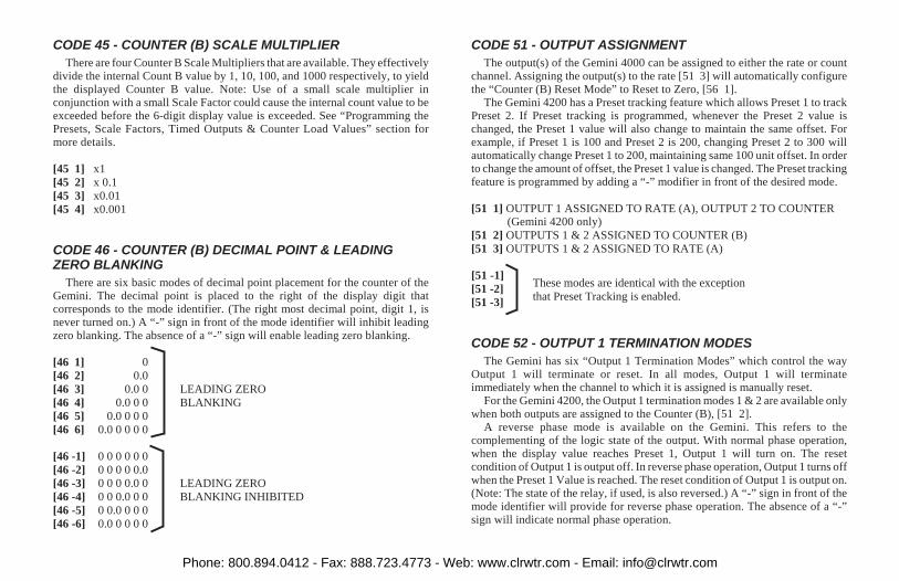
CODE 45 - COUNTER (B) SCALE MULTIPLIER
There are four Counter B Scale Multipliers that are available. They effectivelydivide the internal Count B value by 1, 10, 100, and 1000 respectively, to yieldthe displayed Counter B value. Note: Use of a small scale multiplier inconjunction with a small Scale Factor could cause the internal count value to beexceeded before the 6-digit display value is exceeded. See “Programming thePresets, Scale Factors, Timed Outputs & Counter Load Values” section formore details.
[45 1] x1
[45 2] x 0.1
[45 3] x0.01
[45 4] x0.001
CODE 46 - COUNTER (B) DECIMAL POINT & LEADINGZERO BLANKING
There are six basic modes of decimal point placement for the counter of theGemini. The decimal point is placed to the right of the display digit thatcorresponds to the mode identifier. (The right most decimal point, digit 1, isnever turned on.) A “-” sign in front of the mode identifier will inhibit leadingzero blanking. The absence of a “-” sign will enable leading zero blanking.
[46 1] 0
[46 2] 0.0
[46 3] 0.0 0 LEADING ZERO
[46 4] 0.0 0 0 BLANKING
[46 5] 0.0 0 0 0
[46 6] 0.0 0 0 0 0
[46 -1] 0 0 0 0 0 0
[46 -2] 0 0 0 0 0.0
[46 -3] 0 0 0 0.0 0 LEADING ZERO
[46 -4] 0 0 0.0 0 0 BLANKING INHIBITED
[46 -5] 0 0.0 0 0 0
[46 -6] 0.0 0 0 0 0
CODE 51 - OUTPUT ASSIGNMENT
The output(s) of the Gemini 4000 can be assigned to either the rate or countchannel. Assigning the output(s) to the rate [51 3] will automatically configurethe “Counter (B) Reset Mode” to Reset to Zero, [56 1].
The Gemini 4200 has a Preset tracking feature which allows Preset 1 to trackPreset 2. If Preset tracking is programmed, whenever the Preset 2 value ischanged, the Preset 1 value will also change to maintain the same offset. Forexample, if Preset 1 is 100 and Preset 2 is 200, changing Preset 2 to 300 willautomatically change Preset 1 to 200, maintaining same 100 unit offset. In orderto change the amount of offset, the Preset 1 value is changed. The Preset trackingfeature is programmed by adding a “-” modifier in front of the desired mode.
[51 1] OUTPUT 1 ASSIGNED TO RATE (A), OUTPUT 2 TO COUNTER(Gemini 4200 only)
[51 2] OUTPUTS 1 & 2 ASSIGNED TO COUNTER (B)
[51 3] OUTPUTS 1 & 2 ASSIGNED TO RATE (A)
[51 -1]
[51 -2]These modes are identical with the exception
[51 -3]that Preset Tracking is enabled.
CODE 52 - OUTPUT 1 TERMINATION MODES
The Gemini has six “Output 1 Termination Modes” which control the wayOutput 1 will terminate or reset. In all modes, Output 1 will terminateimmediately when the channel to which it is assigned is manually reset.
For the Gemini 4200, the Output 1 termination modes 1 & 2 are available onlywhen both outputs are assigned to the Counter (B), [51 2].
A reverse phase mode is available on the Gemini. This refers to thecomplementing of the logic state of the output. With normal phase operation,when the display value reaches Preset 1, Output 1 will turn on. The resetcondition of Output 1 is output off. In reverse phase operation, Output 1 turns offwhen the Preset 1 Value is reached. The reset condition of Output 1 is output on.(Note: The state of the relay, if used, is also reversed.) A “-” sign in front of themode identifier will provide for reverse phase operation. The absence of a “-”sign will indicate normal phase operation.
Phone: 800.894.0412 - Fax: 888.723.4773 - Web: www.clrwtr.com - Email: [email protected]

CODE 52 - OUTPUT 1 TERMINATION MODES (Cont’d)
[52 1] TERMINATE AT OUTPUT 2 START - Output 1 will terminate whenOutput 2 starts. Output 1 is set for normal phase operation. (Gemini 4200 Only)
[52 2] TERMINATE AT OUTPUT 2 END - Output 1 will terminate whenOutput 2 ends. Output 1 is set for normal phase operation. (Gemini 4200 Only)
[52 3] TERMINATE AT MANUAL RESET - Output 1 activates when the rateor count, whichever it is assigned to, is greater than or equal to the Preset 1Value. In this mode, once Output 1 is activated, it does not deactivate until themoment a reset occurs. Output 1 is set for normal phase operation.
[52 4] TERMINATE AT MANUAL RESET END - This mode is like thepreceding, except Output 1 deactivates when reset ends. Output 1 is set fornormal phase operation.
[52 5] TERMINATE AFTER TIMED OUTPUT 1 - Once Output 1 has beenactivated, it will deactivate after the predetermined length of time (code 53)has expired. Manual reset will override the timed output and reset Output 1.Output 1 is set for normal phase operation.When Output 1 alone is assigned to the rate [51 1], the output will activatewhen the rate is greater than or equal to the Preset 1 Value. When both outputsare assigned to Rate [51 3], Output 1 will act as an “underspeed” detect. It willactivate when the rate is less than or equal to the Preset 1 Value. Output 1 willactivate every update time period for which the above conditions are true. Ifthe Timed Output 1 Value, code 53, is greater than the rate update time, theoutput will appear to be latched on, deactivating when the rate drops below thePreset and the output time expires.
[52 6] BOUNDARY MODE - When in boundary mode, the Preset 1 Valueserves as the boundary point. When the display value (count or rate) is lessthan the Preset 1 Value, Output 1 is not activated (normal phase). When thedisplay value is greater than or equal to the Preset 1 Value, Output 1 isactivated. If the display value were to drop below Preset 1, Output 1 wouldthen deactivate. For negative Preset points, Output 1 is not activated when thecount value is more positive than the Preset 1 Value. When the count is morenegative than (only possible with counter) or equal to Preset 1, Output 1 isactivated. If the count becomes more positive than the Preset 1 Value, the
output again deactivates. When Output 1 is assigned to the counter and thePreset 1 value is changed, Output 1 will immediately go to the proper state.Upon power up, Output 1, if assigned to Counter B, will “remember” its powerdown boundary condition and go to that state. Output 1 is set for normalphase operation.
[52 -1]
[52 -2]
[52 -3] These modes are the same as above with the exception
[52 -4] that the output is set for reverse phase operation.
[52 -5]
[52 -6]
CODE 53 - TIMED OUTPUT 1 VALUE
The Gemini has the capability of varying the Timed Output 1 Value from 0.01second to 599.99 seconds. When the code is entered, instead of a single modeidentifier digit being displayed, six digits will be shown. Refer to “Programmingthe Presets, Scale Factors, Timed Outputs & Counter Load Values” section formore details about entering. The timed output will be terminated if the unit ismanually reset.
The Timed Output 1 Value is used only when in Timed Output 1 Terminationmode, [52 5].
Note: A Timed Output Value of zero cannot be programmed into the Gemini. If avalue of 0 is entered into the display and the “E” key is pressed, the unit willnot enter the 0, but will stay in the data entry mode. If a new value is notentered, it will time out and the unit will continue to use its previous setting.
CODE 54 - OUTPUT 2 TERMINATION MODES (GEMINI 4200Only)
The Gemini 4200 has six “Output 2 Termination Modes” which control theway Output 2 will terminate or reset. In all modes, Output 2 will terminateimmediately when the channel to which it is assigned is manually reset.
Output 2 termination modes 1 & 2 are available only when both outputs areassigned to the Counter (B), [51 2].
Phone: 800.894.0412 - Fax: 888.723.4773 - Web: www.clrwtr.com - Email: [email protected]

A reverse phase mode is available on the Gemini 4200. This refers to thecomplementing of the logic state of the output. With normal phase operation,when the display value reaches Preset 2, Output 2 will turn on. The resetcondition of Output 2 is output off. In reverse phase operation, Output 2 turns offwhen the Preset 2 Value is reached. The reset condition of Output 2 is output on.(Note: The state of the relay, if used, is also reversed.) A “-” sign in front of themode identifier will provide for reverse phase operation. The absence of a “-”sign will indicate normal phase operation.
[54 1] TERMINATE AT OUTPUT 1 START - Output 2 will terminate whenOutput 1 starts. Output 2 is set for normal phase operation.
[54 2] TERMINATE AT OUTPUT 1 END - Output 2 will terminate whenOutput 1 ends. Output 2 is set for normal phase operation.
[54 3] TERMINATE AT MANUAL RESET - Output 2 activates when the rateor count, whichever it is assigned to, is greater than or equal to the Preset 2Value. In this mode, once Output 2 is activated, it does not deactivate until themoment a reset occurs. Output 2 is set for normal phase operation.
[54 4] TERMINATE AT MANUAL RESET END - This mode is like thepreceding, except Output 2 deactivates when reset ends. Output 2 is set fornormal phase operation.
[54 5] TERMINATE AFTER TIMED OUTPUT 2 - Once Output 2 has beenactivated, it will deactivate after the predetermined length of time (code55) has expired. Manual reset will override the timed output and reset Output2. When assigned to count or rate, Output 2 will activate when the displayvalue is greater than or equal to the Preset 2 Value. Output 2 is set for normalphase operation.
[54 6] BOUNDARY MODE - When in boundary mode, the Preset 2 Valueserves as the boundary point. When the display value (count or rate) is lessthan the Preset 2 Value, Output 2 is not activated (normal phase). When thedisplay value is greater than or equal to the Preset 2 Value, Output 2 isactivated. If the display value were to drop below Preset 2, Output 2 wouldthen deactivate. For negative Preset points, Output 2 is not activated when thecount value is more positive than the Preset 2 Value. When the count is more
negative than (only possible with counter) or equal to Preset 2, Output 2 isactivated. If the count becomes more positive than the Preset 2 Value, theoutput again deactivates. When Output 2 is assigned to the counter and thePreset 2 value is changed, Output 2 will immediately go to the proper state.Upon power up, Output 2, if assigned to Counter B, will “remember” its powerdown boundary condition and go to that state. Output 2 is set for normal phaseoperation. Programming Boundary mode will automatically select [56 1], if[51 1 or 2] is programmed.
[54 -1]
[54 -2]
[54 -3] These modes are the same as above with the exception
[54 -4] that the output is set for reverse phase operation.
[54 -5]
[54 -6]
CODE 55 - TIMED OUTPUT 2 VALUE (GEMINI 4200 Only)
The Gemini 4200 has the capability of varying the Timed Output 2 Value from0.01 second to 599.99 seconds. When the code is entered, instead of a singlemode identifier digit being displayed, six digits will be shown. Refer to“Programming the Presets, Scale Factors, Timed Outputs & Counter LoadValues” section for more details about entering. The timed output will beterminated if the unit is manually reset.
The Timed Output 2 Value is used only when in Timed Output 2 Terminationmode, [54 5].
Note: A Timed Output Value of zero cannot be programmed into the Gemini4200. If a value of 0 is entered into the display and the “E” key is pressed, theunit will not enter the 0, but will stay in the data entry mode. If a new value isnot entered it will time out and the unit will continue to use its previous setting.
Phone: 800.894.0412 - Fax: 888.723.4773 - Web: www.clrwtr.com - Email: [email protected]

CODE 56 - COUNTER (B) RESET MODES
The Gemini 4000 has six different counter reset modes. There are also twomethods by which manual reset can act on the counter (reset must be enabled, seefunction code 66 and dip switch set-up). The first is a “maintained” reset action,where the unit is held at reset for as long as the reset terminal or reset button isactivated. The second is a “momentary” reset, in which the unit resets, when resetis activated, and starts counting even though the terminal or reset button may stillbe active. A “-” sign in front of the mode identifier indicates “momentary” resetaction, the absence of the “-” sign indicates “maintained” reset action.
For the Gemini 4200, if both outputs are assigned to the Rate Channel [51 3],or the Output 2 Termination mode is boundary [54 6], the only Counter (B) Resetmode that is available is Reset to Zero [56 1].
In Reset to Zero modes the Output (if assigned to Counter B) activates at thePreset Value. In Reset to Preset modes the Output activates at zero.
In the “Reset to Preset” modes, for proper operation, the counter normallycounts down. In the “Count with Inhibit” and “Separate Inputs” input responsemodes, [43 1 or 4], the unit will automatically count down if a Reset to Presetmode is selected. In the other input response modes, proper input phasing isrequired for down counting. See “CODE 43 - INPUTS 1 & 2 RESPONSEMODES” section for more details.
Note: The Reset Button & Terminal Actuation Mode must be programmed tomode [42 2 or 3] in order to be able to manually reset the Counter (B). Theactivation and de-activation response time for reset is 10 msec.
Note: For the Gemini 4200, all reset to preset modes reset to preset 2 and TimedOutput refers to Output 2.
[56 1] MANUAL RESET TO ZERO (RTZ) - Manual reset to zero isaccomplished by pulling the “RST.” terminal to “COMMON” or, if the frontpanel reset is enabled, by pressing the front panel reset button. Reset is“maintained”.
[56 2] MANUAL RESET TO PRESET (RTP) - Manual reset to Preset isaccomplished by pulling the “RST.” terminal to “COMMON” or, if the frontpanel reset is enabled, by pressing the front panel reset button. Reset is“maintained”.
[56 3] AUTOMATIC RESET TO ZERO AFTER TIMED OUTPUT - Thecounter automatically resets to zero when Timed Output ends. Manual resetis “maintained” and will override automatic reset. The “Output TerminationMode” should be programmed for timed output operation, [54 5], when inthis mode.
[56 4] AUTOMATIC RESET TO PRESET AFTER TIMED OUTPUT - Thecounter automatically resets to Preset when Timed Output ends. Manual resetis “maintained” and will override automatic reset.
The “Output Termination Mode” should be programmed for timed outputoperation, [54 5], when in this mode.
[56 5] AUTOMATIC RESET TO ZERO AT BEGINNING OF TIMEDOUTPUT (AT PRESET) - In this reset mode, the counter will automaticallyreset to zero at the beginning of Timed Output (at Preset). The Timed OutputValue must be shorter than the time required for the counter to count to thePreset Value, otherwise, the Output will appear to be latched on. Manual resetis “maintained” and will override automatic reset. The “Output TerminationMode” should be programmed for timed output operation, [54 5], when inthis mode.
[56 6] AUTOMATIC RESET TO PRESET AT BEGINNING OF TIMEDOUTPUT (AT ZERO) - In this reset mode, the counter will automatically resetto Preset at the beginning of Timed Output (at zero). The Timed Output Valuemust be shorter than the time required for the counter to count to zero,otherwise, the Output will appear to be latched on. Manual reset is“maintained” and will override automatic reset. The “Output TerminationMode” should be programmed for timed output operation, [54 5], when inthis mode.
[56 -1]
[56 -2]
[56 -3] These modes are the same as above with the exception
[56 -4] that manual reset is set for “momentary” operation.
[56 -5]
[56 -6]
Phone: 800.894.0412 - Fax: 888.723.4773 - Web: www.clrwtr.com - Email: [email protected]
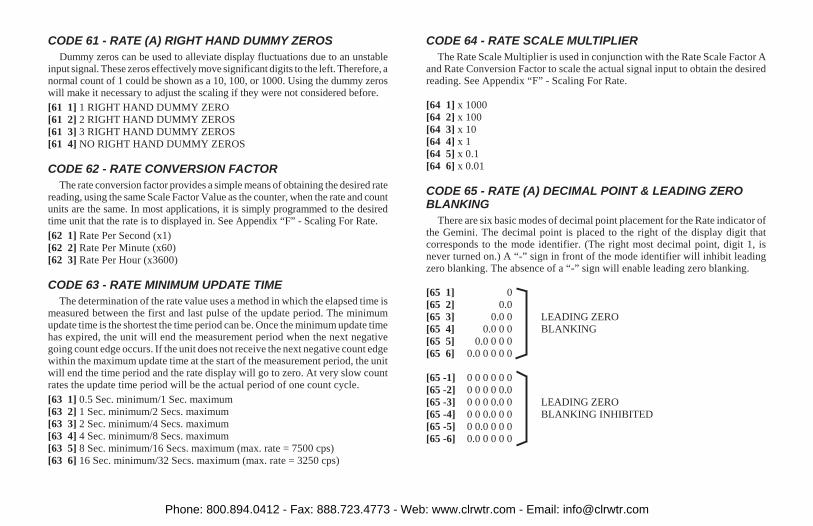
CODE 61 - RATE (A) RIGHT HAND DUMMY ZEROS
Dummy zeros can be used to alleviate display fluctuations due to an unstableinput signal. These zeros effectively move significant digits to the left. Therefore, anormal count of 1 could be shown as a 10, 100, or 1000. Using the dummy zeroswill make it necessary to adjust the scaling if they were not considered before.
[61 1] 1 RIGHT HAND DUMMY ZERO
[61 2] 2 RIGHT HAND DUMMY ZEROS
[61 3] 3 RIGHT HAND DUMMY ZEROS
[61 4] NO RIGHT HAND DUMMY ZEROS
CODE 62 - RATE CONVERSION FACTOR
The rate conversion factor provides a simple means of obtaining the desired ratereading, using the same Scale Factor Value as the counter, when the rate and countunits are the same. In most applications, it is simply programmed to the desiredtime unit that the rate is to displayed in. See Appendix “F” - Scaling For Rate.
[62 1] Rate Per Second (x1)
[62 2] Rate Per Minute (x60)
[62 3] Rate Per Hour (x3600)
CODE 63 - RATE MINIMUM UPDATE TIME
The determination of the rate value uses a method in which the elapsed time ismeasured between the first and last pulse of the update period. The minimumupdate time is the shortest the time period can be. Once the minimum update timehas expired, the unit will end the measurement period when the next negativegoing count edge occurs. If the unit does not receive the next negative count edgewithin the maximum update time at the start of the measurement period, the unitwill end the time period and the rate display will go to zero. At very slow countrates the update time period will be the actual period of one count cycle.
[63 1] 0.5 Sec. minimum/1 Sec. maximum
[63 2] 1 Sec. minimum/2 Secs. maximum
[63 3] 2 Sec. minimum/4 Secs. maximum
[63 4] 4 Sec. minimum/8 Secs. maximum
[63 5] 8 Sec. minimum/16 Secs. maximum (max. rate = 7500 cps)
[63 6] 16 Sec. minimum/32 Secs. maximum (max. rate = 3250 cps)
CODE 64 - RATE SCALE MULTIPLIER
The Rate Scale Multiplier is used in conjunction with the Rate Scale Factor Aand Rate Conversion Factor to scale the actual signal input to obtain the desiredreading. See Appendix “F” - Scaling For Rate.
[64 1] x 1000
[64 2] x 100
[64 3] x 10
[64 4] x 1
[64 5] x 0.1
[64 6] x 0.01
CODE 65 - RATE (A) DECIMAL POINT & LEADING ZEROBLANKING
There are six basic modes of decimal point placement for the Rate indicator ofthe Gemini. The decimal point is placed to the right of the display digit thatcorresponds to the mode identifier. (The right most decimal point, digit 1, isnever turned on.) A “-” sign in front of the mode identifier will inhibit leadingzero blanking. The absence of a “-” sign will enable leading zero blanking.
[65 1] 0
[65 2] 0.0
[65 3] 0.0 0 LEADING ZERO
[65 4] 0.0 0 0 BLANKING
[65 5] 0.0 0 0 0
[65 6] 0.0 0 0 0 0
[65 -1] 0 0 0 0 0 0
[65 -2] 0 0 0 0 0.0
[65 -3] 0 0 0 0.0 0 LEADING ZERO
[65 -4] 0 0 0.0 0 0 BLANKING INHIBITED
[65 -5] 0 0.0 0 0 0
[65 -6] 0.0 0 0 0 0
Phone: 800.894.0412 - Fax: 888.723.4773 - Web: www.clrwtr.com - Email: [email protected]

CODE 66 - “OPERATOR ACCESSIBLE FUNCTIONS” MODES
The Gemini has six basic levels of “Operator Accessible Functions”. Each ofthese levels can be modified to enable or disable manual reset. When the “PGM.DIS.” (Program Disable) terminal is connected to “COMMON”, access to allfunctions is disabled except for those listed below which will remain enabled. Allof the function codes and parameters can be interrogated, regardless of the“Operator Accessible Functions” mode selected.
A “-” sign in front of the mode identifier will disable the front panel Resetbutton and the “RST.” terminal.
Note: The front panel reset button can be independently disabled by using thedisable reset DIP switch.
[66 1] NO FUNCTIONS ENABLED EXCEPT RESET - In this mode, manualreset is enabled, but none of the programming functions can be changed.
[66 2] PRESET PROGRAMMING AND RESET ENABLED - In this mode,manual reset and the programming of the Preset Values are enabled.
[66 3] SCALE FACTOR PROGRAMMING AND RESET ENABLED - In thismode, manual reset and the programming of the Scale Factor Values are enabled.
[66 4] SCALE FACTOR, PRESET PROGRAMMING AND RESETENABLED - In this mode, manual reset and the programming of the ScaleFactor and Preset Values are enabled.
[66 5] PRESET, COUNTER LOAD PROGRAMMING AND RESETENABLED - In this mode, manual reset and the programming of the Presetsand Counter Load Value are enabled.
[66 6] PRESET, SCALE FACTOR, COUNTER LOAD PROGRAMMINGAND RESET ENABLED - In this mode, manual reset and the programming ofthe Presets, Scale Factors and Counter Load Value are enabled.
[66 -1]
[66 -2]
[66 -3] These modes are the same as above with the
[66 -4] exception that manual reset is disabled.
[66 -5]
[66 -6]
PRESET VALUE
Whenever the display value equals the preset value (when output is assignedto that display channel), an output action will occur. This action depends on thepreviously programmed modes. The preset values may range from -999,999 to999,999. (Refer to “Programming the Presets, Scale Factors, Timed Outputs &Counter Load Values” section for instructions on entering the preset values.)
The Counter (B) Scale Factor, SFB, will have a direct effect on the preset valuebeing entered (if assigned to the counter). For a Scale Factor Value greater thanone, the preset value should be an integer multiple of the Scale Factor. If it is not,the Gemini will automatically adjust the preset value up or down to force it to beevenly divisible by the Scale Factor.
“1” - PRESET 1 VALUE“2” - PRESET 2 VALUE (GEMINI 4200 Only)
SCALE FACTORS A & B
“3” SCALE FACTOR - The Scale Factor, for which value (count or rate) iscurrently being displayed, is accessed by pressing the “3” key. To access theScale Factor of the “other” display value, the “+/-” key would be pushed (tochange the display to the other value), then the “3” key would be pushed.
The number of pulses counted (internal count value) is multiplied by the ScaleFactor, which changes the displayed value accordingly. A Scale Factor Value of1.0000 would result in a display of the actual number of input pulses that havebeen counted. The Scale Factor is used primarily for conversion from existingpulses per unit of measure to the required displayed units. This includesconversion from different units of measure (i.e feet to meters, etc.).
The Scale Factor Values may range from -5.9999 to +5.9999 (positive only forRate (A) Scale Factor, SFA). Refer to “Programming the Presets, Scale Factors,Timed Outputs & Counter Load Values” section for entering instructions. It isimportant to note that the precision of a counter application cannot be improvedby using a Scale Factor greater than one. To accomplish greater precision, more
Phone: 800.894.0412 - Fax: 888.723.4773 - Web: www.clrwtr.com - Email: [email protected]

pulse information must be generated per measuring unit. For example, if 5 pulsesare being received per foot of material, the precision of 10th of feet cannot beattained by simply programming a Scale Factor of 2.0000, even though thedisplay is reading in 10ths. In this case, the display will increment by two for eachcount input. Thus if an odd Preset Value was entered, such as 6.7 ft., the Geminiwill alter the preset to read in even tenths of feet.
Note: Use of a small Scale Factor in conjunction with a small scale multipliercould cause the internal count value (counter) to be exceeded before the6-digit display value is exceeded.
COUNTER LOAD VALUE
The Counter Load Value is provided to allow the user to modify the countvalue. The Counter Load Value is reset to zero when the Gemini is powered up.Once the Counter Load Value has been changed, it will remain set to that valueuntil the unit is powered down and up. Accessing the Counter Load Value for thecounter that is currently being displayed is accomplished by pushing the “E”button, and while holding it down, also pushing the “+/-” button. See“Programming the Presets, Scale Factors, Timed Outputs & Counter LoadValues” section for entering instructions.
“E” & “+/-” - Counter Load Value for the currently displayed counter.
Phone: 800.894.0412 - Fax: 888.723.4773 - Web: www.clrwtr.com - Email: [email protected]

DUAL PRESET COUNTER & RATE APPLICATION
A wire screen manufacturer requires a cut to length system, and in addition, aprewarning of an overspeed condition. The cutting machine is equipped with anexisting 12 tooth gear, driving a one foot circumference feed roller.
The Gemini 4200’s counter is to read in feet. When 15,000 feet has beenaccumulated on the take up roll, the counter output is to turn on and deactivate thedrive system. The operator will then make the cut, load a new take up roll andreset the Gemini to start a new roll.
In addition to cut to length, the same Gemini 4200 is to be used to indicate thespeed of the wire screen in feet per minute, while providing a “overspeed”warning. The normal running speed of the material is 225 feet per minute. Themaximum allowable speed of the process is 250 feet per minute.
HARDWARE SETUP
The accompanying drawing shows how the hardware is setup for thisapplication. A Model PSAC proximity sensor is used to sense the teeth on thegear. The application does not require bi-directional counting, so the Gemini4200 will be programmed for the Count with Inhibit “Inputs 1 & 2 ResponseMode”. In this mode, both the rate indicator and counter will utilize the sameinput signal. The switch settings and the wiring connections are as shown. TheInput 2 switch positions 5-7 are set to put the Input 2 in the non-inhibit state withmaximum noise immunity.
SCALING THE COUNTER
In order to scale the counter, the procedure and formulas in Appendix “E” -Scaling for Counting are used.
In converting pulse units to “Display Units”, it is known that 12 pulses areequivalent to 1 revolution of the feed roll, which is equivalent to 1 foot lineartravel of the wire screen. The “Display Unit”, therefore is 1 foot and the “Numberof Pulses” per display unit is 12.
STEP 1 - Calculate the Total Scaling Factor, “KT”, using Formula #1 ofAppendix “E”.
KT = Display Unit / Number of PulsesKT = 1/12 = 0.083333
STEP 2 - Determine the Number of Count Edges, “NCE”, necessary for thisapplication, and calculate the Remaining Scaling required, “KR”, usingFormula #2 of Appendix “E”.Since the Total Scaling Factor, “KT”, is less than 1, single edge counting canbe used, therefore, the Number of Count Edges, “NCE”, is 1.
KR = KT/NCEKR = 0.083333/1 = 0.083333
Phone: 800.894.0412 - Fax: 888.723.4773 - Web: www.clrwtr.com - Email: [email protected]

STEP 3 - Determine the Scale Multiplier Value, “SCM”, and calculate the ScaleFactor, “SF”, using Formula #3 of Appendix “E”.A Scale Multiplier value of 0.1 is chosen to provide the maximum number ofsignificant digits in the Scale Factor.
SF = KR/SCMSF = 0.083333/0.1 = 0.8333
SCALING THE RATE INDICATOR
In this application the rate indicator can be programmed with the same scalefactor and scale multiplier values as obtained when scaling the counter. The onlyother scaling that would be required is choosing the proper Rate ConversionFactor, to obtain the display in the desired time units. The application calls for therate to be indicated in feet per minute, therefore, the Rate Per Minute RateConversion Factor is selected.
STEP BY STEP PROGRAMMING OF THE GEMINI 4200
STEP 1 - Enter code 41 (Unit Personality). Select and enter a mode identifier of1, for the Gemini to operate as a Counter and Rate indicator.
STEP 2 - Enter code 42 (Reset Button & Terminal Actuation Modes). Select andenter mode 2 to reset the counter when reset is activated.
STEP 3 - Enter code 43 (Inputs 1 & 2 Response Modes). Select and enter mode 1,“Count with Inhibit”.
STEP 4 - Enter code 44 (Counter B Number of Count Edges). Select and entermode 1 for single edge counting.
STEP 5 - Enter code 45 (Counter B Scale Multiplier). Select and enter mode 2 fora scale multiplier of 0.1.
STEP 6 - Enter code 46 (Counter B Decimal Point & Leading Zero Blanking).Select and enter mode 1 for no decimal point.
STEP 7 - Enter code 51 (Output Assignment). Select and enter mode 1 to assignOutput 1 to the rate indicator and Output 2 to the counter.
STEP 8 - Enter code 52 (Output 1 Termination Modes). Select and enter mode 6for boundary operation. Output 1 will activate when the maximum speedvalue, Preset 1, is exceeded. Output 1 will deactivate when the rate decreasesto a value below the maximum speed.Note: The Timed Output 1 Value, code 53, is not used in this application.
STEP 9 - Enter code 54 (Output 2 Termination Modes). Select and enter mode 4for Output 2 Terminate at Manual Reset.Note: The Timed Output 2 Value, code 55, is not used in this application.
STEP 10 - Enter code 56 (Counter B Reset Modes). Select and enter mode 1 formanual reset to zero.
STEP 11 - Enter code 61 (Rate Right Hand Dummy Zeros). Select and entermode 4 for no right hand dummy zeros.
STEP 12 - Enter code 62 (Rate Conversion Factor). Select and enter mode 2 for aRate Per Minute conversion factor.
STEP 13 - Enter code 63 (Rate Minimum Update Time). Select and enter mode 1for a minimum update time of 0.5 Second. If the rate display jumps around, alarger minimum update time can be used to provide averaging.
STEP 14 - Enter code 64 (Rate Scale Multiplier). Select and enter mode 5 for aScale Multiplier of 0.1, as previously determined.
STEP 15 - Enter code 65 (Rate Decimal Point & Leading Zero Blanking). Selectand enter mode 1 for no decimal point.
STEP 16 - Enter code 66 (Operator Accessible Functions Modes). Select andenter mode (+)1 for no functions except reset enabled. When the “PGM.DIS.”terminal is connected to “COMM.”, the only changes that will be possible isresetting the counter.
STEP 17 - The “+/-” key is pushed, if necessary, so that the rate is being indicatedon the Gemini 4200. The “3” key is then pushed to call up the Rate ScaleFactor. The value is changed to 0.8333.
STEP 18 - The “+/-” key is pushed, so that the count is being indicated on theGemini 4200. The “3” key is then pushed to call up the Counter Scale Factor.The value is changed to 0.8333.
STEP 19 - Enter a Preset 1 value of 250, by pushing the “1” key and changing thevalue to 250.
STEP 20 - Enter a Preset 2 value of 15,000, by pushing the “2” key and changingthe value to 15,000.After the unit is programmed, the “PGM. DIS.” terminal is connected to“COMM.” to prevent any unauthorized or accidental mode changes. Thefunction codes can, however, be called up to view or verify that the propermodes are entered.
Phone: 800.894.0412 - Fax: 888.723.4773 - Web: www.clrwtr.com - Email: [email protected]

PROGRAMMING INSTRUCTIONS FOR THE DUAL COUNTER VERSION OF THE GEMINI 4000
The first part of this section provides detailed descriptions of the functioncommand codes for input response modes, reset modes, output terminations, etc.Then, using an actual application example, the programming instructions for theDual Counter version will be “walked through”, to give the user a fullunderstanding of the Gemini 4000 programming procedure. The descriptionsbelow give the function command code first, followed by the individual modeidentifier. The Function Command Code Summary in the appendix, lists allcodes. (Only commands and modes pertaining to the Dual Counter personalitywill be discussed in this section.)
CODE 41 - UNIT PERSONALITY
The Gemini can be programmed to operate in one of two different unitpersonalities. In each of the two personalities the Gemini operates as a dualfunction indicator. The personality selected determines whether display channelA will indicate rate or count. In both personalities, display channel B operates asa counter.
When the Unit Personality is changed and entered, all modes and data values(Presets, Scale Factors, function codes, etc.) will be automatically loaded withthe factory settings for that personality. If, for any reason during programming, itis desired to return to the factory settings, the “+/” key can be pushed while incode 41. Then, when the “E” key is pressed the unit will load the factory settingsinto the Gemini.
The programming procedures for the two unit personalities will vary. Thisentire section deals with the unit programmed as a Dual Counter indicator, [41 2].
[41 1] COUNTER (B)/RATE (A) - In this mode, display channel A functions as arate indicator and display channel B functions as a counter. See“PROGRAMMING INSTRUCTIONS FOR COUNTER/RATE VERSIONOF THE GEMINI” section for details.
[41 2] DUAL COUNTER - In this mode, both display channels A & Bfunction as counters.
CODE 42 - RESET BUTTON & TERMINAL ACTUATIONMODES
The “Reset Button & Terminal Actuation modes” control the affect that thereset button and terminal have on the two display channels.
There is a separate “Rst A” terminal which resets Counter A, when activated.It is provided to allow independent resetting of each channel.
[42 1] RESET COUNTER A
[42 2] RESET COUNTER B
[42 3] RESET COUNTER A & B
CODE 43 - INPUTS 1 & 2 RESPONSE MODES
The Gemini has six different input response modes. They are: Count(1) withInhibit(2); Count(1) with Up/Down Control (2); Two input anticoincidenceAdd(1)/Subtract(2); Separate Input mode; Quadrature; and Quadrature x4. In allmodes, except [43 4], both counters will respond identically to both inputs.These modes are most suitable for applications where one channel is used forcontrol, and the other for totalizing counts.
[43 1] COUNT WITH INHIBIT - Input 1 serves as the count input. Input 2 servesas the Inhibit input. When Input 2 is low, the counters will ignore the countsignal appearing at Input 1. When Input 2 is at a high level, the pulsesappearing at Input 1 will be counted.
[43 2] COUNT WITH UP/DOWN CONTROL - In this mode, count directioncan be controlled by the second input. Input 1 serves as the count input andInput 2 serves as the direction control signal input. When Input 2 is at a highlevel, the counters will count up. When Input 2 is at a low level, the counterswill count down.
[43 3] TWO INPUT ANTICOINCIDENCE ADD/SUBTRACT - This modeeffectively separates count pulses which may simultaneously appear at thetwo inputs. The Gemini unit processes the count pulses into a string oftime-separated pulses, so the internal counters will not lose any counts. Input 1serves as the add input (count increments) and Input 2 serves as the subtractinput (count decrements).
Phone: 800.894.0412 - Fax: 888.723.4773 - Web: www.clrwtr.com - Email: [email protected]

[43 4] SEPARATE INPUT - In this mode, the two counters, A & B, areindependently controlled by the inputs. Input 1 serves as the Counter A inputand Input 2 serves as the Counter B input.
[43 5] QUADRATURE COUNTING - Quadrature counting modes are primarilyused in positioning and anti-jitter applications. The reason this mode works isdue to the manner in which two pickups are positioned relative to each other.The signal on Input 2 is a pulse train signal shifted 90° away from the signal onInput 1. These two signals are processed by the Gemini as follows:Input 1 serves as the count input, while Input 2 serves as the quadrature input.For quadrature with single edge counting, the counters will count in a positivedirection when Input 1 is a negative going edge and Input 2 is at a low level.The counters will count in a negative direction when Input 1 is a positive goingedge and Input 2 is at a low level. All transitions on Input 1 are ignored whenInput 2 is at a high level. These logic rules provide the basis for anti-jitteroperation which will prevent false counts from occurring due to back-lash,vibration, chatter, etc.When two edge counting is used, the quadrature mode works the same as withsingle edge counting when Input 2 is low. But when Input 2 is at a high level,counts at Input 1 are no longer ignored. Instead the logic rules for Input 1 arecomplemented, allowing both edges of Input 1 to be counted. This doubles theeffective resolution of the encoded input.
[43 6] QUADRATURE TIMES 4 - This mode takes the quadrature mode, withtwo edge counting, one step further. In quadrature times 4, both Input 1 andInput 2 serve as the count or quadrature input, depending on their state. In oneinstance, Input 1 will serve as the count input and Input 2 will serve as thequadrature input. In another instance, Input 1 will be the quadrature input andInput 2 will be the count input. This enables each edge, positive and negativegoing, of both inputs, 1 and 2, to be counted. This results in a resolution fourtimes greater than in the basic quadrature x1 mode.
CODE 44 - COUNTERS A & B NUMBER OF COUNT EDGES
The counters of the Gemini can be programmed for either single or two edge(x2) counting. The number of count edges cannot be set when the count mode isprogrammed for quadrature x4 operation. The Gemini will ignore any attempt toenter function command code 44, when set for quadrature x4.
[44 1] SINGLE EDGE COUNTING (x1) - The unit counts on the negative going(falling) edge of the count input signal. The Inputs 1 & 2 Response modedescriptions describe how each mode uses this method of edge counting.
[44 2] TWO EDGE COUNTING (x2) - This mode is used when doubling of thecount signal input is required. The unit counts on the positive going (rising)edge of the count input signal, as well as, the negative going (falling) edge.
CODE 45 - COUNTER B SCALE MULTIPLIER
There are four “Counter B Scale Multipliers” that are available. Theyeffectively divide the internal count B value by 1, 10, 100, and 1000 respectively,to yield the displayed Counter B value. Note: Use of a small scale multiplier inconjunction with a small Scale Factor could cause the internal count value to beexceeded before the 6-digit display value is exceeded. See “Programming thePresets, Scale Factors, Timed Outputs & Counter Load Values” section formore details.
[45 1] x1
[45 2] x0.1
[45 3] x0.01
[45 4] x0.001
Phone: 800.894.0412 - Fax: 888.723.4773 - Web: www.clrwtr.com - Email: [email protected]

CODE 46 - COUNTER B DECIMAL POINT & LEADING ZEROBLANKING
There are six basic modes of decimal point placement for Counter B of theGemini. The decimal point is placed to the right of the display digit thatcorresponds to the mode identifier. (The right most decimal point, digit 1, isnever turned on.) A “-” sign in front of the mode identifier will inhibit leadingzero blanking. The absence of a “-” sign will enable leading zero blanking.
[46 1] 0
[46 2] 0.0
[46 3] 0.0 0 LEADING ZERO
[46 4] 0.0 0 0 BLANKING
[46 5] 0.0 0 0 0
[46 6] 0.0 0 0 0 0
[46 -1] 0 0 0 0 0 0
[46 -2] 0 0 0 0 0.0
[46 -3] 0 0 0 0.0 0 LEADING ZERO
[46 -4] 0 0 0.0 0 0 BLANKING INHIBITED
[46 -5] 0 0.0 0 0 0
[46 -6] 0.0 0 0 0 0
CODE 51 - OUTPUT ASSIGNMENT
The output of the Gemini 4100 is assigned to Counter B, or for the Gemini4200 one can be assigned to Counter B and the other to Counter A. When both areassigned to Counter B, the Gemini will automatically configure the Counter AReset Mode to Reset to Zero, [61 1].
The Gemini 4200 has a Preset tracking feature which allows Preset 1 to trackPreset 2. If Preset tracking is programmed, whenever the Preset 2 value is changed,the Preset 1 value will also change to maintain the same offset. For example, ifPreset 1 is 100 and Preset 2 is 200, changing Preset 2 to 300 will automaticallychange Preset 1 to 200, maintaining the same 100 unit offset. In order to change theamount of offset, the Preset 1 value is changed. The Preset tracking feature isprogrammed by adding a “-” modifier in front of the desired mode.
[51 1] OUTPUT 1 ASSIGNED TO COUNTER A, OUTPUT 2 ASSIGNED TOCOUNTER B (Gemini 4200 Only)
[51 2] OUTPUT 1 & 2 ASSIGNED TO COUNTER (B)
CODE 52 - OUTPUT 1 TERMINATION MODES
The Gemini has six “Output Termination Modes”, which control the wayOutput 1 will terminate or reset. In all modes, Output 1 will terminateimmediately when the counter to which it is assigned is manually reset.
Output 1 termination modes 1 & 2 are available only with a Gemini 4200 andwhen both outputs are assigned to Counter B, [51 2].
A reverse phase mode is available on the Gemini. This refers to thecomplementing of the logic state of the output. With normal phase operation,when the display value reaches the Preset 1, Output 1 will turn on. The resetcondition of Output 1 is output off. In reverse phase operation, the Output 1 turnsoff when the Preset 1 is reached. The reset condition of Output 1 is output on.(Note: The state of the relay, if used, is also reversed.) A “-” sign in front of themode identifier will provide for reverse phase operation. The absence of a “-”sign will indicate normal phase operation.
[52 1] TERMINATE AT OUTPUT 2 START - Output 1 will terminate whenOutput 2 starts. Output 1 is set for normal phase operation. (Gemini 4200 Only)
[52 2] TERMINATE AT OUTPUT 2 END - Output 1 will terminate whenOutput 2 ends. Output 1 is set for normal phase operation. (Gemini 4200 Only)
[52 3] TERMINATE AT MANUAL RESET - Output 1 activates when theCounter A or Counter B value, whichever it is assigned to, is greater than orequal to the Preset 1 Value. In this mode, once Output 1 is activated, it doesnot deactivate until the moment a reset occurs. Output 1 is set for normalphase operation.
[52 4] TERMINATE AT MANUAL RESET END - This mode is like thepreceding, except Output 1 deactivates when reset ends. Output 1 is set fornormal phase operation.
Phone: 800.894.0412 - Fax: 888.723.4773 - Web: www.clrwtr.com - Email: [email protected]

[52 5] TERMINATE AFTER TIMED OUTPUT 1 - Once the output has beenactivated, it will deactivate after the predetermined length of time (code 53)has expired. Manual reset will override the timed output and reset Output 1.Output 1 is set for normal phase operation.
[52 6] BOUNDARY MODE - When in boundary mode, the Preset 1 Value servesas the boundary point. When the Counter A or B Value (whichever it is assignedto) is less than Preset 1, Output 1 is not activated (normal phase). When theCounter A or B Value is greater than or equal to Preset 1, Output 1 is activated. Ifthe Counter A or B Value were to drop below Preset 1, Output 1 would thendeactivate. For negative Preset points, Output 1 is not activated when theCounter A or B Value is more positive that the Preset 1 Value. When the count ismore negative than or equal to Preset 1, Output 1 is activated. If the countbecomes more positive than Preset 1, Output 1 again deactivates. When thePreset 1 value is changed, Output 1 will immediately go to the proper state.Upon power up, Output 1 will “remember” its power down boundary conditionand go to that state. Output 1 is set for normal phase operation. ProgrammingBoundary mode will automatically select [61 1] when [51 1] is programmed.
[52 -1]
[52 -2]
[52 -3] These modes are the same as above with the exception
[52 -4] that the output is set for reverse phase operation.
[52 -5]
[52 -6]
CODE 53 - TIMED OUTPUT 1 VALUE
The Gemini has the capability of varying the Timed Output 1 Value from 0.01second to 599.99 seconds. When the code is entered, instead of a single modeidentifier digit being displayed, six digits will be shown. Refer to “Programmingthe Presets, Scale Factors, Timed Outputs & Counter Load Values” section formore details about entering. The timed output will be terminated if the unit ismanually reset.
Note: A Timed Output Value of zero cannot be programmed into the Gemini. If avalue of 0 is entered into the display and the “E” key is pressed, the unit willnot enter the 0, but will stay in the data entry mode. If a new value is notentered, it will time out and the unit will continue to use its previous setting.
CODE 54 - OUTPUT 2 TERMINATION MODES
The Gemini 4200 has six “Output 2 Termination Modes”, which control theway Output 2 will terminate or reset. In all modes, Output 2 will terminateimmediately when Counter B is manually reset.
Output 2 termination modes 1 & 2 are available only when both outputs areassigned to Counter B, [51 2].
A reverse phase mode is available on the Gemini 4200. This refers to thecomplementing of the logic state of the output. With normal phase operation,when the display value reaches the Preset 2, Output 2 will turn on. The resetcondition of Output 2 is output off. In reverse phase operation, the Output 2 turnsoff when the Preset 2 is reached. The reset condition of Output 2 is output on.(Note: The state of the relay, if used, is also reversed.) A “-” sign in front of themode identifier will provide for reverse phase operation. The absence of a “-”sign will indicate normal phase operation.
[54 1] TERMINATE AT OUTPUT 1 START - Output 2 will terminate whenOutput 1 starts. Output 2 is set for normal phase operation.
[54 2] TERMINATE AT OUTPUT 1 END - Output 2 will terminate whenOutput 1 ends. Output 2 is set for normal phase operation.
[54 3] TERMINATE AT MANUAL RESET - Output 2 activates when CounterB is greater than or equal to the Preset 2 Value. In this mode, once Output 2 isactivated, it does not deactivate until the moment a reset occurs. Output 2 is setfor normal phase operation.
[54 4] TERMINATE AT MANUAL RESET END - This mode is like thepreceding, except Output 2 deactivates when reset ends. Output 2 is set fornormal phase operation.
[54 5] TERMINATE AFTER TIMED OUTPUT 2 - Once Output 2 has beenactivated, it will deactivate after the predetermined length of time (code 55)has expired. Manual reset will override the timed output and reset Output 2.Output 2 is set for normal phase operation.
Phone: 800.894.0412 - Fax: 888.723.4773 - Web: www.clrwtr.com - Email: [email protected]

CODE 54 - OUTPUT 2 TERMINATION MODES (Cont’d)
[54 6] BOUNDARY MODE - When in boundary mode the Preset 2 Value servesas the boundary point. When the Counter B Value is less than Preset 2, Output2 is not activated (normal phase). When the Counter B Value is greater than orequal to Preset 2, Output 2 is activated. If the Counter B Value were to dropbelow Preset 2, Output 2 would then deactivate. For negative Preset points,Output 2 is not activated when the Counter B Value is more positive that thePreset 2 Value. When the count is more negative than or equal to Preset 2,Output 2 is activated. If the count becomes more positive than Preset 2, Output2 again deactivates. When the Preset 2 value is changed, Output 2 willimmediately go to the proper state. Upon power up, Output 2 will “remember”its power down boundary condition and go to that state. Output 2 is set fornormal phase operation.Programming Boundary mode will automatically select [56 1].
[54 -1]
[54 -2]
[54 -3] These modes are the same as above with the exception
[54 -4] that the output is set for reverse phase operation.
[54 -5]
[54 -6]
CODE 55 - TIMED OUTPUT 2 VALUE (GEMINI 4200 ONLY)
The Gemini 4200 has the capability of varying the Timed Output 2 Value from0.01 second to 599.99 seconds. When the code is entered, instead of a singlemode identifier digit being displayed, six digits will be shown. Refer to“Programming the Presets, Scale Factors, Timed Outputs & Counter LoadValues” section for more details about entering. The timed output will beterminated if the unit is manually reset.
Note: A Timed Output Value of zero cannot be programmed into the Gemini 4200.If a value of 0 is entered into the display and the “E” key is pressed, the unit willnot enter the 0, but will stay in the data entry mode. If a new value is not entered,it will time out and the unit will continue to use its previous setting.
CODE 56 - COUNTER B RESET MODES
The Gemini has six different Counter B reset modes. Note: For Gemini 4200all reset to preset modes reset to preset 2. There are also two methods by whichmanual reset can act on the counter (reset must be enabled, see function code 66and dip switch set-up). The first is a “maintained” reset action, where the unit isheld at reset for as long as the reset terminal or reset button is activated. Thesecond is a “momentary” reset, in which the unit resets, when reset is activated,and starts counting even though the reset terminal or reset button may still beactive. A “-” sign in front of the mode identifier indicates “momentary” resetaction, the absence of the “-” sign indicates “maintained” reset action.
In “Reset to Zero” modes the Output activates at the Preset Value. In “Reset toPreset” modes, the Output activates at zero.
In the “Reset to Preset” modes, for proper operation, the counter normallycounts down. In the “Count with Inhibit” and “Separate Inputs” input responsemodes, [43 1, or 4], the unit will automatically count down if a Reset to Presetmode is selected. In the other input response modes, proper input phasing isrequired for down counting. See “CODE 43 - INPUTS 1 & 2 RESPONSEMODES” section for details.
The activation and de-activation response time for reset is 10 msec.
[56 1] MANUAL RESET TO ZERO (RTZ) - Manual reset to zero isaccomplished by pulling the “RST.” terminal to “COMMON” or, if the frontpanel reset is enabled, by pressing the front panel reset button. Reset is“maintained”.
[56 2] MANUAL RESET TO PRESET (RTP) - Manual reset to Preset isaccomplished by pulling the “RST.” terminal to “COMMON” or, if the frontpanel reset is enabled, by pressing the front panel reset button. Reset is“maintained”.
[56 3] AUTOMATIC RESET TO ZERO AFTER TIMED OUTPUT - Thecounter automatically resets to zero when Timed Output ends. Manual reset is“maintained” and will override automatic reset.
[56 4] AUTOMATIC RESET TO PRESET AFTER TIMED OUTPUT - Thecounter automatically resets to Preset when Timed Output ends. Manual resetis “maintained” and will override automatic reset.
Phone: 800.894.0412 - Fax: 888.723.4773 - Web: www.clrwtr.com - Email: [email protected]

[56 5] AUTOMATIC RESET TO ZERO AT BEGINNING OF TIMEDOUTPUT (AT PRESET) - In this reset mode, the counter will automaticallyreset to zero at the beginning of Timed Output (at Preset). The Timed OutputValue must be shorter than the time required for the counter to count to thePreset 2 Value, otherwise, the Output will appear to be latched on. Manualreset is “maintained” and will override automatic reset.
[56 6] AUTOMATIC RESET TO PRESET AT BEGINNING OF TIMEDOUTPUT (AT ZERO) - In this reset mode, the counter will automatically resetto Preset at the beginning of Timed Output (at zero). The Timed Output Valuemust be shorter than the time required for the counter to count to zero,otherwise, the Output will appear to be latched on. Manual reset is“maintained” and will override automatic reset.
[56 -1]
[56 -2]
[56 -3] These modes are the same as above with the exception
[56 -4] that manual reset is set for “momentary” operation.
[56 -5]
[56 -6]
CODE 61 - COUNTER (A) RESET MODES
There are two ways to reset Counter A. The reset button or “RST.” terminalcan be used, if the appropriate “Reset Button & Terminal Activation Mode” isprogrammed. The second way is the use of the “RST.A” terminal. If it isnecessary to reset Counter A & B independently, the “Reset Button & TerminalActivation Mode” should be programmed to Reset Counter B, and the “RST.A”terminal should then be used to reset Counter A.
For the Gemini 4200, if both outputs are assigned to Counter B [51 2], or theOutput 1 Termination mode is boundary [54 6], the only Counter A Reset modethat is available is Reset to Zero [61 1].
There are two methods by which manual reset can act on Counter A (reset mustbe enabled - see function code 66 and dip switch set-up). The first is a“maintained” reset action, where the unit is held at reset for as long as the resetterminal or reset button is activated. The second is a “momentary” reset, in whichthe unit resets, when reset is activated, and starts counting even though theterminal or reset button may still be active. A “-” sign in front of the modeidentifier indicates “momentary” reset action, the absence of the “-” signindicates “maintained” reset action.
The activation and de-activation response time for reset is 10 msec.
[61 1] MANUAL RESET TO ZERO (RTZ) - Manual reset to zero isaccomplished by activating the appropriate reset button or terminal. Reset is“maintained”.
The following modes are only available on the Gemini 4200
[61 2] MANUAL RESET TO PRESET 1 (RTP) - Manual reset to Preset 1 isaccomplished by pulling the “RST.” terminal to “COMMON” or, if the frontpanel reset is enabled, by pressing the front panel reset button. Reset is“maintained”.
[61 3] AUTOMATIC RESET TO ZERO AFTER TIMED OUTPUT 1 - Thecounter automatically resets to zero when Timed Output 1 ends. Manual resetis “maintained” and will override automatic reset.
[61 4] AUTOMATIC RESET TO PRESET 1 AFTER TIMED OUTPUT 1 - Thecounter automatically resets to Preset 1 when Timed Output 1 ends. Manualreset is “maintained” and will override automatic reset.
[61 5] AUTOMATIC RESET TO ZERO AT BEGINNING OF TIMEDOUTPUT 1 (AT PRESET 1) - In this reset mode, the counter willautomatically reset to zero at the beginning of Timed Output 1 (at Preset 1).The Timed Output 1 Value (code 53) must be shorter than the time required forthe counter to count to the Preset 1 Value, otherwise, Output 1 will appear to belatched on. Manual reset is “maintained” and will override automatic reset.
[61 6] AUTOMATIC RESET TO PRESET 1 AT BEGINNING OF TIMEDOUTPUT 1 (AT ZERO) - In this reset mode, the counter will automaticallyreset to Preset 1 at the beginning of Timed Output 1 (at zero). The Timed 1Output Value (code 53) must be shorter than the time required for the counterto count to zero, otherwise, Output 1 will appear to be latched on. Manual resetis “maintained” and will override automatic reset.
[61 -1]
[61 -2]
[61 -3] These modes are the same as above with the exception
[61 -4] that manual reset is set for “momentary” operation.
[61 -5]
[61 -6]
Phone: 800.894.0412 - Fax: 888.723.4773 - Web: www.clrwtr.com - Email: [email protected]

CODE 64 - COUNTER A SCALE MULTIPLIER
There are four Counter A scale multipliers that are available. They effectivelydivide the internal Counter A Value by 1, 10, 100, and 1000 respectively, to yieldthe displayed Counter A Value. Note: Use of a small scale multiplier inconjunction with a small Scale Factor could cause the internal Counter A Valueto be exceeded before the 6-digit display value is exceeded.
[64 1] x1
[64 2] x0.1
[64 3] x0.01
[64 4] x0.001
CODE 65 - COUNTER A DECIMAL POINT & LEADING ZEROBLANKING
There are six basic modes of decimal point placement for Counter A of theGemini. The decimal point is placed to the right of the display digit thatcorresponds to the mode identifier. (The right most decimal point, digit 1, isnever turned on.) A “-” sign in front of the mode identifier will inhibit leadingzero blanking. The absence of a “-” sign will enable leading zero blanking.
[65 1] 0
[65 2] 0.0
[65 3] 0.0 0 LEADING ZERO
[65 4] 0.0 0 0 BLANKING
[65 5] 0.0 0 0 0
[65 6] 0.0 0 0 0 0
[65-1] 0 0 0 0 0 0
[65-2] 0 0 0 0 0.0
[65-3] 0 0 0 0.0 0 LEADING ZERO
[65-4] 0 0 0.0 0 0 BLANKING INHIBITED
[65-5] 0 0.0 0 0 0
[65-6] 0.0 0 0 0 0
CODE 66 - “OPERATOR ACCESSIBLE FUNCTIONS” MODES
The Gemini has six basic levels of “Operator Accessible Functions”. Each ofthese levels can be modified to enable or disable manual reset. When the “PGM.DIS.” (program disable) terminal is connected to “COMMON”, access to allfunctions is disabled except for those listed below which will remain enabled. Allof the function codes and parameters can be interrogated, regardless of the“Operator Accessible Functions” mode selected.
A “-” sign in front of the mode identifier will disable the front panel Resetbutton and the “RST.” terminal.
Note: The front panel reset button can be independently disabled by using thedisable reset DIP switch.
[66 1] NO FUNCTIONS ENABLED EXCEPT RESET - In this mode, manualreset is enabled, but none of the programming functions can be changed.
[66 2] PRESET PROGRAMMING AND RESET ENABLED - In this mode,manual reset and the programming of the Preset Values are enabled.
[66 3] SCALE FACTOR PROGRAMMING AND RESET ENABLED - In thismode, manual reset and the programming of the Scale Factor Values are enabled.
[66 4] SCALE FACTOR, PRESET PROGRAMMING AND RESETENABLED In this mode, manual reset and the programming of the ScaleFactor and Preset Values are enabled.
[66 5] PRESET, COUNTER LOAD PROGRAMMING, AND RESETENABLED - In this mode, manual reset and the programming of the Presetsand Counter Load Values are enabled.
[66 6] PRESET, SCALE FACTOR, COUNTER LOAD PROGRAMMING,AND RESET ENABLED - In this mode, manual reset and the programming ofthe Preset, Scale Factor and Counter Load Values are enabled.
[66 -1]
[66 -2]
[66 -3] These modes are the same as above with
[66 -4] the exception that reset is disabled.
[66 -5]
[66 -6]
Phone: 800.894.0412 - Fax: 888.723.4773 - Web: www.clrwtr.com - Email: [email protected]

PRESET VALUES
Whenever the display value equals the preset value, an output action will occur. Thisaction depends on the previously programmed modes. The preset values may vary from-999,999 to 999,999. (Refer to “Programming the Presets, Scale Factors, Timed Outputs& Counter Load Values” for instructions on entering the preset values.)
The Scale Factor will have a direct effect on the preset value being entered. For a ScaleFactor Value greater than one, the preset value should be an integer multiple of the ScaleFactor. If it is not, the Gemini will automatically adjust the preset value up or down toforce it to be evenly divisible by the Scale Factor.
“1” - PRESET 1 VALUE“2” - PRESET 2 VALUE (GEMINI 4200 Only)
SCALE FACTORS A & B
“3” SCALE FACTOR - The Scale Factor, for the Value (Counter A or Counter B)that is currently being displayed, is accessed by pressing the “3” key. To access the ScaleFactor of the “other” display value, the “+/-” key would be pushed (to change the displayto the other value), then the “3” key would be pushed.
The number of pulses counted (internal count value) is multiplied by the Scale Factor,which changes the displayed value accordingly. A Scale Factor Value of 1.0000 wouldresult in a display of the actual number of input pulses that have been counted. The ScaleFactor is used primarily for conversion from existing pulses per unit of measure to therequired displayed units. This includes conversion from different units of measure (i.efeet to meters, etc.). The Scale Factor Values may range from -5.9999 to +5.9999. Referto “Programming the Presets, Scale Factors, Timed Output & Counter Load Values” forentering instructions.
It is important to note that the precision of a counter application cannot be improved byusing a Scale Factor greater than one. To accomplish greater precision, more pulseinformation must be generated per measuring unit. For example, if 5 pulses are beingreceived per foot of material, the precision of 10th of feet cannot be attained by simplyprogramming a Scale Factor of 2.0000, even though the display is reading in 10ths. In thiscase, the display will increment by two for each count input. Thus if an odd preset valuewas entered, such as 6.7 ft., the Gemini will alter the preset to read in even tenths of feet.
Note: Use of a small Scale Factor in conjunction with a small scale multiplier could causethe internal count value to be exceeded before the 6-digit display value is exceeded.
COUNTER LOAD VALUES
The Counter Load Value is provided to allow the user to modify theCounter A or B values. The Counter Load Values are reset to zero whenthe Gemini is powered up. Once the Counter Load Value has beenchanged, it will remain set to that value until the unit is powered down andup. Accessing the Counter Load Value for the counter that is currentlybeing displayed is done by pushing the “E” button and while being helddown also pushing the “+/-” button.
“E” & “+/-” - Counter Load Value for the currently displayed counter.
Phone: 800.894.0412 - Fax: 888.723.4773 - Web: www.clrwtr.com - Email: [email protected]

DUAL COUNTER BATCHING APPLICATION
A typical application for the Gemini 4200 will require a slow down output anda final cut output for cut. In this application the user also desires a total count ofpieces cut per shift, or per order. The Gemini 4200 can easily be programmed tohandle these requirements.
A manufacturer of cardboard packaging inserts needs to cut various lengthcardboard inserts to a 32ndth of an inch tolerance. To achieve this accuracy, anRPGB 1200 coupled to a length sensor conversion bracket and a 1 footcircumference wheel will be used. The sensor will provide 1200 pulses per foot or100 pulses per inch. This will enable the cut be made to 100th of an inch accuracy.
The length of the cardboard insert will vary from run to run, however the slowdown output needs to occur 5 inches before the final cut is to be made. Thisrequirement can be handled easily with the Gemini 4200’s preset trackingfeature. The Preset 1 value is initially programmed to be 5 inches less than thePreset 2 value. (Preset 2 must be programmed first.) Then whenever the length ofthe cardboard insert is changed (Preset 2), the Gemini will automatically adjustPreset 1 to be 5 inches less than the new Preset 2 value.
The last requirement is to totalize the number of pieces cut. This is achieved byusing the output cut pulse at “O2 SNK”, as an input count pulse to Input 1 of theGemini 4200. The Inputs 1 & 2 Response mode of the unit would be programmedto the “Separate Inputs” mode. Then, whenever a cut is made, the Gemini wouldincrement Counter A to provide a total count of pieces cut.
HARDWARE SET-UP
The application drawing shows how the hardware for this system is to beconnected.
The normally open contact of relay 1 is connected to the slow down actuator.The normally open contact of relay 2 is connected to the knife actuator. The “O2SNK” output is connected to Input 1, which will provide a input pulse to CounterA each time a piece is cut.
The Dip switches are setup as shown. Input 1 is set-up to work with an opencollector output. The number of pieces cut will be far less than 100/ sec. thereforethe “HI/LO FRQ” switch for Input 1 is placed in the “LO FRQ” position forhigher noise immunity. Input 2 is also set-up to work with an open collectoroutput. The “HI/LO FRQ” switch is placed in the “HI FRQ” position since thecount frequencies involved will be over 100 cps. The “EN/DIS RST” switch (8),is set to “EN RST” to allow front panel reset.
SCALING FOR COUNTER A
Counter A is used to totalize the number of pieces cut. There is 1 pulseprovided for each piece cut. Counter A, therefore, does not require specialscaling. The Gemini 4200 is simply left at its factory settings of 1 for Scale FactorA and Scale Multiplier A.
Phone: 800.894.0412 - Fax: 888.723.4773 - Web: www.clrwtr.com - Email: [email protected]

SCALING FOR COUNTER B
Counter B is used to control the length of the cardboard insert. The displayreading for Counter B is to be in hundredths of an inch. The “Number of Pulses”per 1200 “Display Units” (1200 hundredths of an inch = 1 foot) is 1200. It caneasily be seen that 1 pulse will provide for 1 “Display Unit” of indication (1hundredth of an inch). The Gemini 4200 can therefore be left at its Scale Factor Band Scale Multiplier B factory settings of 1. The “Counter A & B Number ofCount Edges”, code 44, is also left at the factor set value of 1.
STEP BY STEP PROGRAMMING OF THE GEMINI 4200
STEP 1 - Enter code 41 (Unit Personality). Select and enter mode 2 to set the UnitPersonality to Dual Counter.
STEP 2 - Enter code 42 (“Reset Button & Terminal Actuation Mode”). Selectand enter mode 2 so reset will reset Counter B. This will allow Counter B to bereset when the front panel reset button is pushed.
STEP 3 - Enter code 43 (“Inputs 1 & 2 Response Modes”). Select and enter mode 4for Separate Inputs mode (Input 1 = Counter A input, Input 2 = Counter B input).
STEP 4 - Enter code 44 (“Counters A & B Number of Count Edges”). Select andenter mode 1 for single edge counting.
STEP 5 - Enter code 45 (Counter B Scale Multiplier). Select and enter mode 1 fora scale multiplier of 1.
STEP 6 - Enter code 46 (Counter B Decimal Point & Lead Zero Blanking).Select and enter mode 3 for a decimal point in the hundredths location.
STEP 7 - Enter code 51 (Output Assignment). Select and enter mode (-)2 toassign both outputs to Counter B and enable preset tracking.
STEP 8 - Enter code 52 (Output 1 Termination Modes). Select and enter mode 2for termination at Output 2 end.Note: The Timed Output 1 Value, code 53 is not used in this application.
STEP 9 - Enter code 54 (Output 2 Termination Modes). Select and enter mode 5for timed output operation.
STEP 10 - Enter code 55 (Timed Output 2 Value). Change the value to 0.50 andenter.
STEP 11 - Enter code 56 (Counter B Reset Modes). Select and enter mode 5 forAutomatic Reset to Zero at Preset 2.Note: Code 61 (Counter A Reset Modes) was automatically selected to mode1, Reset to Zero, when mode [51 2] was programmed.
STEP 12 - Enter code 64 (Counter A Scale Multiplier). Select and enter mode 1for a scale multiplier of 1.
STEP 13 - Enter code 65 (Counter A Decimal Point & Leading Zero Blanking).Select and enter mode 1 for no decimal point.
STEP 14 - Enter code 66 (Operator Accessible Functions Modes). Select andenter mode 2 for Preset programming and reset enabled. When the“PGM.DIS.” terminal is connected to “COMM.”, the only changes that will bepossible are resetting the unit and changing the Preset.
The Gemini 4200 in now fully programmed. Jumper the “PGM.DIS.” terminalto “COMM.” to prevent accidental program changes and to enable the “OperatorAccessible Functions”.
Phone: 800.894.0412 - Fax: 888.723.4773 - Web: www.clrwtr.com - Email: [email protected]

20 MA CURRENT LOOP COMMUNICATIONS
The Gemini 4000’s 20 mA Current Loop Communications Option allows a“two-way” serial communications link to be established in order to monitor thecount, rate, Presets and Scale Factors from a remote location. Some typicaldevices that can be connected with the Gemini are: a printer, terminal,programmable controller, or host computer. For devices that use RS232, a GCMSerial Converter Module is available to convert the 20 mA Current Loop signalsto RS232 and vice-versa.
There are two loops that must be established. One for sending commands tothe Gemini and one for receiving the data values from the Gemini. Up to sixteenGeminis can be connected together in the “loop”. These units are assigned unitaddresses by setting the Serial DIP Switches on each unit. The applications canbe as simple as attaching a printer to obtain hard copy of the count information oras involved as using a host computer to automatically set up the Presets and ScaleFactors of a number of Gemini units.
With the Serial Loop Option, the following functions can be performed:1. Interrogation of the Count, Rate, Presets, and Scale Factors.2. Changing of the Presets and Scale Factors.3. Resetting of the Count values.4. Automatic print-out when using a printer and the Print Request Terminal.5. Change viewed display channel.
COMMUNICATION FORMAT
Data is sent by switching off and on the current in the 20 mA current loop. Datais received by monitoring the switching action and interpreting the codes that aretransmitted. In order for data to be interpreted correctly, there must be identicalformats and Baud Rates. The format that the Gemini will accept is: 1 start bit, 7data bits, 1 odd parity bit, and 1 stop bit. The Baud Rates that are available are:300, 600, 1200 and 2400.
The selection of the Baud Rate is accomplished by setting DIP switches. Referto the Current Loop Installation section, for set-up instructions.
SENDING COMMANDS & DATA TO THE GEMINI
When sending commands to the Gemini, a command string must beconstructed. The command string may consist of command codes, valueidentifiers, and numerical data. Below is a list of commands and value identifiersthat are used when communicating with the Gemini.
COMMAND DESCRIPTION
N (4EH) Address command; followed by a unit address number 1-15and one of the following commands.
P (50H) Transmit per Print Options command.
R (52H) Reset command; operates on Count values and output
T (54H) Transmit Value command; operates on Rate or Count values,Preset and Scale Factors.
V (56H) Change Value command; operates on Scale Factors, and thePreset.
D (44H) Change Display command; operates on Display values E & F.
VALUEIDENTIFIER
DESCRIPTION MNEMONIC
A (41H) Preset 1 (PS1)
B (42H) Preset 2 (PS2)
C (43H) Scale Factor A (SFA)
D (44H) Scale Factor B (SFB)
E (45H) Rate or Count A (CTA)
F (46H) Count B (CTB)
FIG. 1: DATA FORMAT-10 BIT FRAME [300, 600, 1200, 2400 Baud]
Phone: 800.894.0412 - Fax: 888.723.4773 - Web: www.clrwtr.com - Email: [email protected]

The command string is constructed by using the above commands and valueidentifiers along with the data values that are required. Data values may or maynot contain the decimal point if a decimal point is programmed into the Gemini.The Gemini will accept the decimal points, however, it does not interpret them inany way. Leading zeros can be eliminated, however, all trailing zeros must bepresent. For example, if a Scale Factor of 1.0000 is to be sent, the data value canbe transmitted as 1.0000 or 10000. If a “1” is transmitted, the Scale Factor will bechanged to 0.0001.
The Address command is used to allow a command to be directed to a specificunit in the Serial Communications Loop. Whenever the unit address is zero,transmission of the Address command is not required. This is done forapplications which do not require more than one Gemini. For applications thatrequire several units, it is recommended that each Gemini in the loop be given aseparate address. If they are given the same address, a command such as theTransmit Value Command, will cause all the units to respond at the same time,resulting in erroneous data.
The command string is constructed in a specific logical sequence. The Geminiwill not accept command strings that do not follow this sequence. Only oneoperation can be performed per command string. Below is the procedure to beused when constructing a command string.
1. If the Gemini, to which the command is to be sent, is assigned an address otherthan zero, the first two characters of the command string must consist of theAddress Command (N) and the address number of the unit (1-15).
2. The next characters in the command string is the actual command that theGemini is to perform and the value identifier if it pertains to the command. (Acommand such as the Transmit per Print Options, “P”, command does notrequire a Value Identifier.)
3. If the “Change Value” command is being used, the next characters in thecommand string is the numerical data value.
4. The last character in the command string is the command terminator (*). Thischaracter must be sent in order to tell the Gemini that the command string iscomplete, so that they can begin processing the command.
Below are some typical examples of properly constructed command strings.
(EX. 1) Change Preset 1 on the Gemini with address of 2 to 00123.4.
COMMAND STRING: N2VA1234*(EX. 2) Have the Gemini with address of 3 transmit the Count B value.
COMMAND STRING: N3TF*(EX. 3) Reset Counter B of the Gemini with address of 0.
COMMAND STRING: RF*
As shown, all commands must be terminated with a “Command Terminator”(* or 2AH). The Gemini will not process the command until the terminator issent. If illegal commands or characters are sent to the Gemini, they still wouldneed to be terminated by an (*). If they are not terminated, the next command willnot be accepted.
When writing application programs in Basic, the transmission of spaces orcarriage return and line feed should be inhibited by using the semicolon delimiterwith the “PRINT” statement. The Gemini will not accept a carriage return or linefeed as valid characters.
When a “Change Value” command is sent to the Gemini, a short amount oftime is required for the unit to process the data. This time increases with the countrate. During this time, only one additional command may be sent to the Gemini.This may be done 80 msec after the transmission of the “Change Value”command. After the second command has been transmitted, the unit will ignoreany further commands until 10 msec after both the “Change Value” and secondcommand have been processed. It is recommended that a “Transmit Value”command follow a “Change Value” Command. If this is done, the reception ofthe data can provide a timing reference for sending another command and willinsure that the change has occurred.
Phone: 800.894.0412 - Fax: 888.723.4773 - Web: www.clrwtr.com - Email: [email protected]

SENDING COMMANDS & DATA TO THE GEMINI (Cont’d)
The timing diagrams show the timing considerations that need to be made.
RECEIVING DATA FROM THE GEMINI
Data is transmitted from the Gemini when a “Transmit Value” or “Transmitper Print Options” command is sent to the unit, or when the “PRINT REQ.”terminal is activated. The Gemini can transmit 6 values: display channel A,display channel B, Preset 1, Preset 2, Scale Factor A, and Scale Factor B. A list ofthe abbreviations used when the Gemini transmits the values are shown below.
CTA - Counter A or Rate A ValueCTB - Counter B ValuePS1 - Preset 1PS2 - Preset 2SFA - Scale Factor ASFB - Scale Factor B
A typical transmission, with the “PR. ID” (Print ID) switch in the up position,is shown below.
The first two digits transmitted are the unit address followed by two blankspaces. If the unit address is 0, the first locations will be left blank. The next threeletters are the abbreviation for the mnemonic value followed by one blank space.The actual values are transmitted last. Negative values are indicated by a “-”sign. For positive values, the “+” sign is not transmitted. Overflowed countvalues are shown by an asterisk preceding the most significant digit of the value.The decimal point position will “float” within the data field depending on theactual value it represents.
For peripheral control purposes, a single line transmission will have a <CR>attached to the end of the above string. For a “T” command or each line of a blocktransmission, only the above character string is sent. For the last line of a blocktransmission, a <SP> <CR> <LF> is attached to the end of the above characterstring. An example of a typical serial transmission:
3 CTB -1234.56 < CR> < LF>
If the “Print Request” terminal initiates the transmission, a 400 msec delay isinserted before the transmission to keep multiple transmissions fromoverrunning the printer.
When the Print ID switch is in the down position, the unit will not transmit thecharacters before the data value (address, Value ID, spaces) or the 400 msecprinter delay. The same above value when transmitted with the “PR.ID” switchin the down position, is transmitted as:
-1234.56 < CR> < LF>
Note: When using the Gemini with a printer, with the “Print ID” switch in thedown position, some printers may not work, since the printer delay is nottransmitted.
FIG. 2: TIMING FOR SENDING COMMANDS
(**) This is the time that it takes the Gemini 4000 to process the preset.It varies with the Count Rate and Scale Factor Value.
FIG. 3: RESET COMMAND TIMING
Phone: 800.894.0412 - Fax: 888.723.4773 - Web: www.clrwtr.com - Email: [email protected]

PRINT OPTIONS
The various Print Options are used mainly in conjunction with a printer andthe Print Request Terminal. They provide a choice of Gemini data values to beprinted when either the Print Request Terminal is activated or the “Transmit perPrint Options” (P) command is sent to the Gemini. The various Print Optionsavailable are:
A. Print Display A count or rate valueB. Print Display B Count ValueC. Print Display A & B ValuesD. Print Preset 1 & 2 and Scale Factors A & BE. Print Display B, Presets 1 & 2, and Scale Factors A & BF. Print Display A, Presets 1 & 2, and Scale Factors A & BG. Print Display A & B, Presets 1 & 2, and Scale Factors A & B
A typical print-out is shown below. The Print Options are selected by setting S3,S4 and S5 on the Serial DIP Switch. See Page 34 for the various switch settings.
1 CTA 0000541 PS1 0001001 PS2 0005001 SFA 01.00001 SFB 02.5000
Phone: 800.894.0412 - Fax: 888.723.4773 - Web: www.clrwtr.com - Email: [email protected]

CURRENT LOOP INSTALLATION
WIRING CONNECTIONS
When wiring the 20 mA current loop, remove the 7-position terminal block(TBD), located on the right side of the top board. Refer to the numbers listed withthe terminal descriptions below or on the top label, and install each wire in itsproper location on the terminal block. When all connections are made, replacethe terminal block into its proper location.
It is recommended that shielded (screened) cable be used for serialcommunications. This unit meets the EMC specifications using ALPHA #2404cable or equivalent. There are higher grades of shielded cable, such as, fourconductor twisted pair, that offer an even higher degree of noise immunity.
TERMINAL DESCRIPTIONS FOR TERMINAL BLOCK TBD
1. -20 mA SRC (COMM.) - Common2. PRINT REQUEST - The Print Request Terminal is pulled low to request the
Gemini to transmit according to the Print Options mode that has been selected.(Minimum Activation time = 25 msec.)
3. +20 mA SRC - The 20 mA SRC terminal provides the source current for one ofthe loops.
4. SO- (Serial Out-) -5. SO+ (Serial Out+) -
The Gemini transmits the requested data on these terminals. They areconnected in series to the receive input of the device to be connected.6. SI- (Serial In-) -7. SI+ (Serial In+) -
The Gemini receives commands on these terminals. They are connected inseries with the transmit or output terminals of the device to be connected.
Note: The serial Input terminals must be held in the mark condition (current on)in order for the Gemini to respond to a Print Request terminal activation.
SERIAL DIP SWITCH SET-UP
The Serial DIP switches are accessible through the side of the Gemini. A list ofthe DIP switch positions and their functions are shown in the figure at right.
BR0 & BR1, BAUD RATE - Set-up is shown , at right. When changing the BaudRate, the unit should be powered-down and then powered back up again. Theunit will only recognize a baud rate change upon power-up, after activating the
“Print Request” terminal or after a few characters have been sent at the newbaud rate (If the two previous conditions have not occurred, the Gemini willsee the characters as erroneous and it will check the baud rate and set itself tooperate at the new rate).
PR.ID - PRINT ID. - When this switch is in the up position, the Gemini will printthe unit address, data value ID and the data value when a transmission isrequested. The unit will also insert a 400 msec delay between transmissionswhen the “P” command or Print Request terminal is used. This switchposition is generally used when the unit is connected with a printer.When the switch is in the down position, the Gemini will transmit only the datavalue, without the unit address and data ID. The 400 msec delay, described above,will not be inserted. This switch position usage is intended for applications wherethe Gemini is communicating with a computer. In these circumstances printingthe address and value ID and inserting a 400 msec print delay is usuallyunnecessary and needlessly slows down communication throughput.
PC0, PC1, & PC2, PRINT OPTIONS - Used to control which values areprinted out when the Print Request terminal is activated or when the Transmitper Print Options command “P” is sent to the Gemini 4000.
AD0, AD1, AD2, & AD3 UNIT ADDRESS - These switches are used to giveeach unit a separate address when more than one unit is connected in the Loop.See below for Switch Set-up.
Phone: 800.894.0412 - Fax: 888.723.4773 - Web: www.clrwtr.com - Email: [email protected]

PROCESS MONITORING SYSTEM
Five Geminis with 20 mA Current Loop Option, are used tomonitor and control parts packaging machines in a plant. Theunits are located at each of the machines in the production areaof the building. The communications lines are run to anIndustrial computer located in the production offices.
[OTHER GEMINIS OR RLC PRODUCTS WITH 20 MA CURRENT LOOP
CAN BE CONNECTED IN THE SAME LOOP.]
The drawing below shows the Current Loop set-up. EachGemini is given an address and the Serial DIP switches are setaccordingly. A Baud Rate of 1200 is selected and set in each ofthe Geminis. An application program is written, which sendsand retrieves data from the units using the Change andTransmit Value commands.
NOTE: The Gemini DC out (terminals 4 & 5)
could be used in place of the external 12
VDC supply.
COMMUNICATIONS APPLICATION
Phone: 800.894.0412 - Fax: 888.723.4773 - Web: www.clrwtr.com - Email: [email protected]

TROUBLESHOOTING GEMINI SERIAL COMMUNICATIONS
If problems are encountered when trying to get the Gemini(s) and hostdevice or printer to communicate, the following checklist can be used to help findthe solution.
1. Check all wiring. Refer to the previous application examples and use them as aguide to check your serial communication wiring. Proper polarity of allGeminis and other peripherals must be observed. If a multimeter or ammeter isavailable, insert it in series in each Serial loop and check for current flow withall units powered up. If no current is flowing, either the loop is not wiredcorrectly, or some other fault has occurred. If too much current has been sentthrough a Serial Input or Output, the unit may have been damaged. If a Geminiis suspected, it can be tested for operation by using the Serial Loop-back testdescribed in the next section.
2. If the Gemini is set-up with a “host computer”, device or printer, check tomake sure that the computer or device is configured with the samecommunication format as the Gemini. The only communication format theGemini will accept is; 1 start bit, 7 data bits, odd parity, and 1 stop bit.
3. Check the baud rate settings and make sure all devices in the loop are set to thesame baud rate.
4. Check the Gemini’s unit address. If the Address command is not used whentransmitting a command to the Gemini, the Gemini’s address must be set to 0.See “Sending Commands & Data to the Gemini” section for commandstructure.
5. If two-way communications are to be established between the Gemini and acomputer, try getting the computer to receive transmissions from the Geminifirst. The Gemini’s “PRINT REQ.” terminal can be used to initiate thetransmissions from the Gemini.
6. When sending commands to the Gemini, the * (2Ah) must terminate thecommand. NO CARRIAGE RETURNS (0Dh) OR LINE FEED (0Ah)CHARACTERS SHOULD BE SENT TO THE GEMINI. If they are sent, theGemini will not respond to the next command.
7. For applications where 1200 Baud or lower is used, the command terminator (*)can be sent before the string to eliminate any illegally transmitted characters.
SERIAL LOOP-BACK SELF-TEST
The Gemini has a Serial Loop-back Self-test feature. This test enables the userto verify the operation of the Gemini when problems are encountered trying toget the Gemini and “Host device” communicating. In this test, the Gemini’sSerial Input and Output Loops are connected together with the 20 mA sourcesupplying the loop current. The Gemini then transmits data “to itself”. If the datais received properly, the Gemini will change its Scale Factor B value to 0.1111.To perform the loop-back test, follow the test sequence as described below.
1. With the unit powered down, wire up the serial terminal block, “TBD”, asshown in the diagram below.
2. Set the Gemini’s unit address to 15 (set switches 7-10 of the Serial DIP Switchto the down position).
3. Apply power to the unit. On power-up the Gemini will perform the loop-backtest. To check the results: Call up the Scale Factor B value by pressing the “3”key while the Counter B value is being displayed. If the Serial loop isfunctioning properly the Scale Factor B value will be 0.1111. If this result isnot obtained, double check the connections with those shown in the diagram,and the unit address switch positions and repeat step 3.
4. If the connection between the Print Request terminal, “PRINT REQ.” and“COMMON” is disconnected while the unit is under power, the Scale FactorB value will change back to its previous setting.
If the unit does not pass this test, contact your local Red Lion Controls distributor.
Phone: 800.894.0412 - Fax: 888.723.4773 - Web: www.clrwtr.com - Email: [email protected]

APPENDIX “A” - INSTALLATION & INPUT CONFIGURATION SWITCH SET-UP
Before installing the Gemini into the panel, the user should first becomefamiliar with the unit. It may also be desirable to program the unit and appropriateDIP switches for the application at hand (Refer to the “Programming andApplications” sections). Once the unit is programmed, the settings will be savedin memory. The Program Disable “PGM. DIS.” terminal should be connected to“COMM.” to prevent accidental or unauthorized programming changes.
Installation Environment
The unit should be installed in a location that does not exceed the maximumoperating temperature and provides good air circulation. Placing the unit neardevices that generate excessive heat should be avoided.
The bezel should be cleaned only with a soft cloth and neutral soap product.Do NOT use solvents. Continuous exposure to direct sunlight may accelerate theaging process of the bezel.
Do not use tools of any kind (screwdrivers, pens, pencils, etc.) to operate thekeypad of the unit.
PANEL MOUNTING Note: See Appendix “B” for dimensionsThe Gemini is intended to be mounted into an enclosed panel with a gasket
to provide a water-tight seal. The unit meets NEMA 4/IP65 requirements forindoor use when properly installed. Two mounting clips and screws areprovided for easy installation. Consideration should be given to the thicknessof the panel. A panel which is too thin may distort and not provide awater-tight seal. (Recommended minimum panel thickness is 1/8".)
After the panel cut-out has been completed and deburred, remove thebacking from the adhesive side of the gasket, and carefully apply the gasket
to the panel. DO NOT APPLY THE ADHESIVE SIDE OF THE
GASKET TO THE COUNTER BEZEL. Insert the unit into the panel.Install the screws into the narrow ends of the mounting clips as shown in thedrawing to the left. Thread the screws into the clips until the pointed endjust protrudes through the other side.
Install each of the two mounting clipsby inserting the wide lip of the clips intothe wide end of the holes located on eitherside of the case. Tighten the screwsevenly, applying uniform compression,thus providing a water-tight seal.CAUTION: Only minimum pressure isrequired to seal panel. Do NOT overtighten mounting screws.
Phone: 800.894.0412 - Fax: 888.723.4773 - Web: www.clrwtr.com - Email: [email protected]

SELECT AC POWER (115/230 VAC)
The AC power to the unit must be selected for either 115 VAC or 230 VAC.The selector switch is located through an access slot on the side of the case (Seethe Installation Figure on the previous page, or the label on the case). The unit isshipped from the factory with the switch in the 230 VAC position.Caution: Damage to the unit may occur if the AC selector switch is set incorrectly.
EMC Compliance Installation
This unit complies with the Electromagnetic Compatibility (EMC) standardslisted in the specifications. Compliance to the EMC standards was demonstratedby means of a test set-up using the following installation methods:1. Unit mounted in a metal panel connected to earth ground (protective earth).2. Shielded (screened) cables for Signal and Control inputs with shield drain wire
connected to earth ground at the mounting panel only.Belden #8451 2 conductor, #22 AWGtwisted pairwith foil shield and drain wireBelden #8771 3 conductor, #22 AWG with foil shield and drain wireAlpha #2404 4 conductor, #22 AWG with foil shield and drain wire
3. Metal bezel of unit connected to mounting panel with 9 inch (23 cm) groundlead from rear bezel screw. Test: Immunity to ESD per EN61000-4-2.
4. Shaffner FN610 EMI Filter placed on DC mains cable when using optional DCpower. Test: Electrical Fast transients (burst) (EFT) EN 61000-4-4.
5. Shaffner FN610 EMI Filter placed on DC mains cable when using optional DCpower supply. Test: RF Conducted Immunity per ENV 50141.
Shield TerminationEMC compliance installation testing had the drain wire for the shielded cable
terminated as shown. The drain wire was less than 0.5" (12.7 mm) long.
Phone: 800.894.0412 - Fax: 888.723.4773 - Web: www.clrwtr.com - Email: [email protected]

Additional EMC Installation GuidelinesAlthough this unit is designed with a high degree of immunity to
ElectroMagnetic Interference (EMI), proper installation and wiring methodsmust be followed to ensure compatibility in each application. The type of theelectrical noise, source or coupling method into the unit may be different forvarious installations. Listed below are some additional EMC guidelines forsuccessful installation in an industrial environment.1. The unit should be mounted in a metal enclosure, which is properly connected
to protective earth.a. If the bezel is exposed to high Electro-Static Discharge (ESD) levels,
above 4 Kv, it should be connected to protective earth. This can be doneby making sure the metal bezel makes proper contact to the panel cut-outor connecting the bezel screw with a spade terminal and wire toprotective earth.
2. Use shielded (screened) cables for all Signal and Control inputs. The shield(screen) pigtail connection should be made as short as possible. Theconnection point for the shield depends somewhat upon the application.Listed below are the recommended methods of connecting the shield, in orderof their effectiveness.a. Connect the shield only at the panel where the unit is mounted to earth
ground (protective earth).b. Connect the shield to earth ground at both ends of the cable, usually
when the noise source frequency is above 1 MHz.c. Connect the shield to common of the unit and leave the other end of the
shield unconnected and insulated from earth ground.3. Never run Signal or Control cables in the same conduit or raceway with AC
power lines, conductors feeding motors, solenoids, SCR controls, and heaters,etc. The cables should be run in metal conduit that is properly grounded. Thisis especially useful in applications where cable runs are long and portabletwo-way radios are used in close proximity or if the installation is near acommercial radio transmitter.
4. Signal or Control cables within an enclosure should be routed as far away aspossible from contactors, control relays, transformers, and other noisycomponents.
5. In very electrically noisy environments, the use of external EMI suppressiondevices, such as ferrite suppression cores, is effective. Install them on Signaland Control cables as close to the unit as possible. Loop the cable through thecore several times or use multiple cores on each cable for additional protection.
Install line filters on the power input cable to the unit to suppress power lineinterference. Install them near the power entry point of the enclosure. Thefollowing EMI suppression devices (or equivalent) are recommended:Ferrite Suppression Cores for signal and control cables:
Fair-Rite # 0443167251 (RLC #FCOR0000)TDK # ZCAT3035-1330ASteward #28B2029-0A0
Line Filters for input power cables:Schaffner # FN610-1/07 (RLC #LFIL0000)Schaffner # FN670-1.8/07Corcom #1VR3
Note: Reference manufacturer’s instructions when installing a line filter.6. Long cable runs are more susceptible to EMI pickup than short cable runs.
Therefore, keep cable runs as short as possible.7. Switching of inductive loads produces high EMI. Use of snubbers across
inductive loads suppresses EMI.Snubbers:
RLC #SNUB0000
WIRING CONNECTIONS
After the unit has been mechanically mounted, it is ready to be wired. Allwiring connections are made on removable plug-in terminal blocks. There is aseparate terminal block for the bottom board (TBA), relay board (TBB), countinputs (TBC), and optional Serial Communications (TBD). When wiring theunit, remove the terminal block and use the numbers on the label to identify theposition number with the proper function. Simply strip the wire, leavingapproximately ¼" bare wire exposed (stranded wires should be tinned withsolder). Insert the wire into the terminal and tighten down the screw until the wireis clamped in tightly. Each terminal can accept up to two 18-gage wires. After theterminal block is wired, install it in the proper location on the PC board. Wireeach terminal block in this manner.
All conductors should meet voltage and current ratings for each terminal. Alsocabling should conform to appropriate standards of good installation, local codesand regulations. It is recommended that power supplied to the unit (AC or DC) beprotected by a fuse or circuit breaker.
Phone: 800.894.0412 - Fax: 888.723.4773 - Web: www.clrwtr.com - Email: [email protected]

POWER WIRING
AC VersionsAC Power Wiring
Primary AC power is connected to terminals 1 and 2, labeled AC. To reduce thechance of noise spikes entering the AC line and affecting the counter, an AC feedseparate from that of the load should be used to power the counter. Be certain thatthe AC power to the counter is relatively “clean” and within the specified range.Connecting power from heavily loaded circuits or circuits that also power loadsthat cycle on and off, (contacts, relays, motors, etc.) should be avoided.
The voltage selector switch, located on the side of the unit, is used to select theproper voltage. The switch is a slide movement type and can be set by using a smallscrewdriver. If the switch is towards the front of the unit, it is set for 230 VACinput. The switch is in the 230 VAC position when shipped from the factory.Note: Before applying power to the unit, make sure the AC power selector switch
is set for the proper voltage setting.
DC Power WiringThe DC power is connected to terminals 3 & 5, marked DC IN and COMM.
respectively. The DC power source must be capable of supplying the unit’s ratedcurrent (700 mA max.) and be within the specified 11 to 14 VDC range. Thepower source can be a 12 V battery or an external power supply that is capable ofsupplying the unit’s rated current. It is not necessary to provide battery backup toretain count information. The Gemini has non-volatile memory that storesinformation on power down, thereby eliminating the need for battery back-up.
Output Power
DC OUT terminal provides a DC output for sensor power (+12 VDC ±25%).The maximum sensor current is 100 mA. This terminal number is modeldependent. Refer to the label on the unit for correct number.
RELAY WIRING
To prolong contact life and suppress electrical noise interference due to theswitching of inductive loads, it is good installation practice to install a snubberacross the contactor. Follow the manufacturer’s instructions for installation.Note: Snubber leakage current can cause some electro-mechanical devices to be
held ON.
SERIAL COMMUNICATIONS
The Gemini can be purchased with a 20 mA Current Loop CommunicationsOption. On these units, refer to the “Current Loop Communications” section ofthe manual, for wiring and operational procedures of the Serial Loop.
INPUT 1 & MAGNETIC PICKUP INPUT
The Magnetic Pickup Input and Logic Input 1 utilize some common circuitry.For this reason the Input 1 switches are used to set up both the Magnetic andLogic Input 1. S1 selects between Magnetic Pickup Input and Logic Input 1.WHEN A MAGNETIC PICKUP IS BEING USED, S2 MUST BE IN THE“SNK” POSITION or the unit will not count.
S3 (HI/LO FRQ) and S4 (HI/LO BIAS) do not effect the Magnetic PickupInput and their settings are inconsequential. When S1 is in the Logic position, theMagnetic Pickup Input is disabled and Input 1 can be used as a logic input.
Note: A Magnetic Pickup type sensor should not be used unless a large enoughsignal is provided at all speeds of operation.
INPUT 2
Input 2 is designed specifically for Logic type inputs. When Input 1 is set upfor Logic operation, both Inputs 1 and 2 operate identically. DIP switch positionsS5, S6, and S7 function the same as S2, S3, and S4.
Phone: 800.894.0412 - Fax: 888.723.4773 - Web: www.clrwtr.com - Email: [email protected]

INSTALLATION & REMOVAL OF THE RELAY BOARD
To install the relay board, locate the relay opening at the lower right-handcorner, on the back of the Gemini. Pull the tab down while sliding the board intothe two slots in the housing. The relay board will seat into the unit, allowing thetab to return to its original position. To remove the relay board, pull down on thetab just enough to allow the relay board to slide out. Grasp the terminal block andpull to remove the board.
NOTES:
1. SENSOR VOLTAGE AND CURRENTThe +12 V sensor supply voltage on the “DC OUT” terminal is nominal with+/-25% variation due to line and internal load variations. All RLC sensorswill accommodate this variation.
2. HI/LO FRQ SELECTIONThe HI/LO FRQ selection switch must be set on “LO FRQ” when switchcontacts are used to generate count input signals. Since the “LO FRQ” modealso provides very high immunity against electrical noise pickup, it isrecommended that this mode also be used, whenever possible, with electronicsensor outputs. The “LO FRQ” mode can be used with any type of sensoroutput, provided count pulse widths never decrease below 5 msec, and thecount rate does not exceed 100 cps.
3. VIL and VIH levels given are nominal values +/-10% when counter voltage on“DC OUT” terminal is +12 VDC. These nominal values will vary inproportion to the variations in the “DC OUT” terminal voltage, which arecaused by line voltage and load changes.
4. When shielded cable is used, the shield should be connected to “COMM.” atthe counter and left unconnected at the sensor end.
5. Inputs 1 and 2 can accept source pulses from other circuits up to +28 V inamplitude. For voltages above +28 V, a limiting resistor and zener diodeshould be used to limit the voltage at the input.
Phone: 800.894.0412 - Fax: 888.723.4773 - Web: www.clrwtr.com - Email: [email protected]

CONNECTIONS & CONFIGURATION SWITCH SET-UPS FOR VARIOUS SENSOR OUTPUTS (See Note 5)
Phone: 800.894.0412 - Fax: 888.723.4773 - Web: www.clrwtr.com - Email: [email protected]

Phone: 800.894.0412 - Fax: 888.723.4773 - Web: www.clrwtr.com - Email: [email protected]

Phone: 800.894.0412 - Fax: 888.723.4773 - Web: www.clrwtr.com - Email: [email protected]
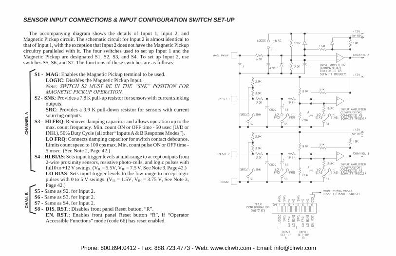
SENSOR INPUT CONNECTIONS & INPUT CONFIGURATION SWITCH SET-UP
The accompanying diagram shows the details of Input 1, Input 2, andMagnetic Pickup circuit. The schematic circuit for Input 2 is almost identical tothat of Input 1, with the exception that Input 2 does not have the Magnetic Pickupcircuitry paralleled with it. The four switches used to set up Input 1 and theMagnetic Pickup are designated S1, S2, S3, and S4. To set up Input 2, useswitches S5, S6, and S7. The functions of these switches are as follows:
S1 - MAG: Enables the Magnetic Pickup terminal to be used.
LOGIC: Disables the Magnetic Pickup Input.Note: SWITCH S2 MUST BE IN THE “SNK” POSITION FORMAGNETIC PICKUP OPERATION.
S2 - SNK: Provides a 7.8 K pull-up resistor for sensors with current sinkingoutputs.
SRC: Provides a 3.9 K pull-down resistor for sensors with currentsourcing outputs.
S3 - HI FRQ: Removes damping capacitor and allows operation up to themax. count frequency. Min. count ON or OFF time - 50 usec (U/D orINH.), 50% Duty Cycle (all other “Inputs A & B Response Modes”).
LO FRQ: Connects damping capacitor for switch contact debounce.Limits count speed to 100 cps max. Min. count pulse ON or OFF time -5 msec. (See Note 2, Page 42.)
S4 - HI BIAS: Sets input trigger levels at mid-range to accept outputs from2-wire proximity sensors, resistive photo-cells, and logic pulses withfull 0 to +12 V swings. (VIL = 5.5V, VIH = 7.5 V, See Note 3, Page 42.)LO BIAS: Sets input trigger levels to the low range to accept logicpulses with 0 to 5 V swings. (VIL = 1.5V, VIH = 3.75 V, See Note 3,Page 42.)
S5 - Same as S2, for Input 2.
S6 - Same as S3, for Input 2.
S7 - Same as S4, for Input 2.
S8 - DIS. RST.: Disables front panel Reset button, “R”.
EN. RST.: Enables front panel Reset button “R”, if “OperatorAccessible Functions” mode (code 66) has reset enabled.
CH
AN
.B
CH
AN
NE
LA
Phone: 800.894.0412 - Fax: 888.723.4773 - Web: www.clrwtr.com - Email: [email protected]

APPENDIX “B” - SPECIFICATIONS & DIMENSIONS1. DISPLAY: 6-digit 0.56" (14.2 mm) High LED display.
2. POWER REQUIREMENTS:
AC Versions
AC Power: Switch selectable 115/230 VAC (±10%), 50/60 Hz, 20 VA
DC Power: 11 to 14 VDC @ 0.7 amp maximum
3. SENSOR POWER: +12 VDC (±25%) @ 100 mA.
4. MEMORY: Non-volatile E2PROM memory retains all programminginformation and count values (except Counter Load values) when power isremoved or interrupted.
Power Cycles (ON/OFF): 100,000 minimum
Data Retention: 10 yrs. minimum
5. INPUTS 1 AND 2: Switch selectable to accept count pulses from a variety ofsources including switch contacts, outputs from CMOS or TTL circuits, andall standard RLC sensors.
Current Sourcing - Unit provides pull-down resistor for sensor with currentsourcing outputs. (Max. input voltage = 28 VDC @ 7 mA.)
Current Sinking - Unit provides pull-up resistor for sensors with currentsinking outputs. (Max. sensor current = 1.6 mA.)
Debounce - Damping capacitor provided for switch contact debounce. Limitscount speed to 100 Hz maximum and input pulse widths to 5 msec. minimum.
Lo Bias - Input trigger levels VIL = 1.5 V, VIH = 3.75 V
Hi Bias - Input trigger levels VIL = 5.5 V, VIH = 7.5 VNote: Bias levels given are ±10% @ 12 VDC. They vary proportionally withsensor supply voltage at “DC OUT” terminal.
6. MAGNETIC PICKUP INPUT:
Sensitivity: 150 mV peak (typical @ 12 VDC)
Hysteresis: 100 mV
Input impedance: 26.5 KΩ @ 60 Hz
Maximum Input Voltage: ±50 Vp
7. RATE ACCURACY AND REPEATABILITY: +0.012%
8. RATE MINIMUM INPUT FREQUENCY: 0.03 HzNote: At frequencies below 0.03 Hz (1 pulse every 32 sec.) the rate display willgo to zero.
9. CONTROL INPUTS:
Reset - Active low (VIL = 1.5 V max.), internally pulled up to +12 VDC (ISNK = 3mA), activation and de-activation response time = 10 msec.
Program Disable - Active low (VIL = 1.5 V max.), internally pulled up to +5VDC (ISNK = 1 mA).
Print Request - (Serial Communications) Active low, (VIL = 1.5 V max.),internally pulled up to +5 VDC (ISNK = 1 mA).
10. MAXIMUM COUNT RATES:
NOTE: Mounted units require a clearance of 6.8" (W) behind the panel.DIMENSIONS In inches (mm)
COUNTER/RATE MODE [41 1]
MODE X1 X2 X4Uni or Bi-directional 10 KHz 5 KHzAnti-Coincidence Add/Subtract 4 KHz 2.5 KHzSeparate Input 8 KHz 4 KHzQuadrature 5 KHz 4.5 KHz 2.5 KHz
Phone: 800.894.0412 - Fax: 888.723.4773 - Web: www.clrwtr.com - Email: [email protected]
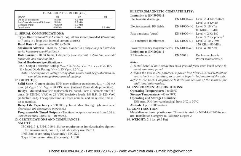
11. SERIAL COMMUNICATIONS:
Type - Bi-directional 20 mA current loop, 20 mA source provided. (Powers upto 7 units in a loop with internal current source.)
Baud Rate - Programmable 300 to 2400.
Maximum Address - 16 units. (Actual number in a single loop is limited byserial hardware specifications.)
Data Format - 10 bit frame, Odd parity (one start bit, 7 data bits, one oddparity bit, and one stop bit.)
Serial Hardware Specifications -SO - Output Transistor Rating: Vmax = 30 VDC, VSAT = 1 Vmax at 20 mASI - Input Diode Rating: VF = 1.25 VTYP; 1.5 Vmax
Note: The compliance voltage rating of the source must be greater than thesum of the voltage drops around the loop.
12. OUTPUT(S):
Solid-State - Current sinking NPN open collector transistors. ISNK = 100 mAmax. @ VCE = 1 V. VOH = 30 VDC max. (Internal Zener diode protection).
Relays - Mounted on a field replaceable PC board. Form C contacts rated at 5amps @ 120/240 VAC or 28 VDC (resistive load), 1/8 H.P. @ 120 VAC(inductive load). The operate time is 5 msec nominal and the release time is 3msec nominal.
Relay Life Expectancy - 100,000 cycles at Max. Rating. (As load leveldecreases, life expectancy increases.)
Programmable Timed Outputs - The timed outputs can be set from 0.01 to599.99 seconds, ±(0.01% + 10 msec.).
13. CERTIFICATIONS AND COMPLIANCES:
SAFETY
IEC 61010-1, EN 61010-1: Safety requirements for electrical equipmentfor measurement, control, and laboratory use, Part 1.
IP65 Enclosure rating (Face only), IEC 529Type 4 Enclosure rating (Face only), UL50
ELECTROMAGNETIC COMPATIBILITY:
Immunity to EN 50082-2
Electrostatic discharge EN 61000-4-2 Level 2; 4 Kv contact 1
Level 3; 8 Kv air
Electromagnetic RF fields EN 61000-4-3 Level 3; 10 V/m
80 MHz - 1 GHz
Fast transients (burst) EN 61000-4-4 Level 4; 2 Kv I/O
Level 3; 2 Kv power 2
RF conducted interference EN 61000-4-6 Level 3; 10 V/rms
150 KHz - 80 MHz
Power frequency magnetic fields EN 61000-4-8 Level 4; 30 A/m
Emissions to EN 50081-2
RF interference EN 55011 Enclosure class A
Power mains class ANotes:
1. Metal bezel of unit connected with ground from rear bezel screw tometal mounting panel.
2. When the unit is DC powered, a power line filter (RLC#LFIL0000 orequivalent) was installed, so as not to impair the function of the unit.
Refer to the EMC Compliance Installation section of the manual foradditional information.
14. ENVIRONMENTAL CONDITIONS:
Operating Temperature: 0 to 50°C
Storage Temperature: -40 to 70°C
Operating and Storage Humidity:85% max. RH (non-condensing) from 0°C to 50°C.
Altitude: Up to 2000 meters
15. CONSTRUCTION:
Metal die-cast bezel, plastic case. This unit is rated for NEMA 4/IP65 indooruse. Installation Category II, Pollution Degree 2
16. WEIGHT: 2.1 lbs. (0.9 Kg)
DUAL COUNTER MODE [41 2]
MODE X1 X2 X4Uni or Bi-directional 9 KHz 4.5 KHzAnti-Coincidence Add/Subtract 5 KHz 2.5 KHzSeparate Input 7.5 KHz 3.5 KHzQuadrature 4.5 KHz 4 KHz 2.5 KHz
Phone: 800.894.0412 - Fax: 888.723.4773 - Web: www.clrwtr.com - Email: [email protected]

APPENDIX “C” - TROUBLESHOOTING GUIDE
The majority of difficulties arising with the Gemini are related to incorrect hook-up and programming set-up. Alwayscheck all connections, function codes, Scale Factors, and preset as a first step in troubleshooting.
Before applying power, double check all wiring. Improper AC voltage or AC connections may result in permanentdamage to the unit.
For further technical assistance, contact technical support at the appropriate company numbers listed on the back ofthis instruction manual.
PROBLEM POSSIBLE CAUSE REMEDIES
NO DISPLAY 1. Power off, improperly connected, or power 1. Check all wiring, verify power.brown-out.
P ON DISPLAY 1. Data error on power-up. 1a. Press “E” key.b. Check all function codes.
E ON THE DISPLAY 1. Data error detected by processor. 1a. Press “E” or “R” button.b. Check all function codes.c. Check signal lines for possible noise sources.
NO RESPONSE TO FRONT PANEL 1. Panel disabled. 1. Consult manual on “Operator AccessibleFunctions" modes.
UNIT DOES NOT COUNT 1. No input. 1. Check sensors/connections.2. Input selected incorrectly. 2. Check rear panel DIP switches.3. Count inhibited. 3. Check function code 43, “Input 1 and 2
Response” modes.4. Scale factor/multiplier too small. 4. Check scale factor value and scale
multiplier values.
UNIT WILL NOT ACCEPT THE DESIRED 1. When counter scale factors greater than 1 are used, 1. Unit automatically adjusts preset to bePRESET the preset value must be evenly divisible by the evenly divisible by the scale factor.
scale factor.
Phone: 800.894.0412 - Fax: 888.723.4773 - Web: www.clrwtr.com - Email: [email protected]

APPENDIX “C” - TROUBLESHOOTING GUIDE (Cont’d)
PROBLEM POSSIBLE CAUSE REMEDIES
UNIT COUNTS INCORRECTLY 1. Input type incorrectly selected. 1. Check rear panel DIP switches. Turn on LOFRQ. switch for count speed of less than100 cps.
2. Inputs incorrectly connected or loose connections. 2. Check sensors/input connections.3. Electrical interference. 3. Check connections and wiring for noise sources.4. Wrong counting mode. 4. Verify functions and modes.5. Scale factor incorrect. 5. Change scale factor value.
UNIT WILL NOT RESET 1. Front panel reset disabled. 1. Check rear panel DIP switch.2. Reset disabled. 2. Check function code 42 or 66.
DATA VALUES AND FUNCTIONS WILL 1. Front panel locked out. 1. Consult manual on “Operator AccessibleNOT CHANGE OR NOT RECORDED Functions" mode (66).
2. Incorrect programming procedure (“E” not pressed). 2. Consult section on programming functions insequential order.
UNIT COUNTS WHILE RESET IS 1. Reset mode set for “momentary reset”. 1. Change reset mode to “Maintained” reset (56).ACTIVATED
Phone: 800.894.0412 - Fax: 888.723.4773 - Web: www.clrwtr.com - Email: [email protected]

CODE MODE DESCRIPTION COMMENTS
41 UNIT PERSONALITY (-)Loads factory set code values*
+/-1 Counter/Rate* Rate Display → value (A)/Counter → Display value (B)
42 RESET BUTTON & TERMINAL ACTUATION MODES
1 Reset Rate Output For Rate, reset only affects the output and does not
2 Reset Counter change the displayed value. For Counter, reset affects the
3 Reset Rate Output & Counter output as well as the count value
43 INPUTS 1 & 2 RESPONSE MODES
1 Count with Inhibit Input 1 = Cnt & Rate, Input 2 = Inh for Cnt.
2 Count with Up/Down Control Input 1 = Cnt & Rate, Input 2 = Up/Dn for Cnt
3 Add/Subtract Input 1 = Add & Rate, Input 2 = Subtract
4 Separate Inputs Input 1 = Rate, Input 2 = Counter
5 Quadrature Input 1 = Cnt & Rate, Input 2 = Quadrature
6 Quadrature x4 Input 1 = Cnt, Quad, & Rate, Input 2 = Cnt & Quad
44 COUNTER NUMBER OF COUNT EDGES Cannot be programmed in Quad x4.
1 Single Edge Counting (x1) Count on falling edge of count input
2 Double Edge Counting (x2) Count on both edges of count input.
45 COUNTER SCALE MULTIPLIER
1 1
2 0.1
3 0.01
4 0.001
46 CNTR DECIMAL POINT & LEAD ZERO BLANKING
- (+) Leading Zero Blanking Enabled
- (-) Leading Zero Blanking Disabled *
+/-1 No Decimal Point
+/-2 Decimal Point Right of Digit 2
+/-3 Decimal Point Right of Digit 3
+/-4 Decimal Point Right of Digit 4
+/-5 Decimal Point Right of Digit 5
+/-6 Decimal Point Right of Digit 6
* Polarity sign is displayed in front of the identifier, a (-) sign is displayed, a (+) sign is not.
APPENDIX “D” - GEMINI COUNTER/RATE MODE FUNCTION COMMAND CODE SUMMARY
Phone: 800.894.0412 - Fax: 888.723.4773 - Web: www.clrwtr.com - Email: [email protected]

APPENDIX “D” - GEMINI COUNTER/RATE MODE FUNCTION COMMAND CODE SUMMARY
CODE MODE DESCRIPTION COMMENTS
51 OUTPUT ASSIGNMENT
(+) Preset Tracking Disabled
(-) Preset Tracking Enabled Preset 1 tracks Preset 2
+/-1 Output 1 to Rate A, Output 2 to Counter B
+/-2 Outputs 1 & 2 to Counter B
+/-3 Outputs 1 & 2 to Rate A Automatically selects code [56,1].
52 OUTPUT 1 TERMINATION MODES
(+) Normal Phase Output normally “OFF”, turns “ON” at preset.
(-) Reverse Phase* Output normally “ON”, turns “OFF” at preset.
+/-1 Terminate at Output 2 Start (Gemini 4200 only) Only available when [51 2]
+/-2 Terminate at Output 2 End (Gemini 4200 only) Only available when [51 2]
+/-3 Terminate at Manual Reset
+/-4 Terminate at Manual Reset End
+/-5 Terminate after Timed Output 1
+/-6 Boundary
53 TIMED OUTPUT 1 VALUE Range 0.01 to 599.99 sec.
54 GEMINI 4200 OUTPUT 2 TERMINATION MODES
(+) Normal Phase Output normally “OFF”, turns “ON” at preset.
(-) Reverse Phase* Output normally “ON”, turns “OFF” at preset.
+/-1 Terminate at Output 1 Start Only available when [51 2]
+/-2 Terminate at Output 1 End Only available when [51 2]
+/-3 Terminate at Manual Reset
+/-4 Terminate at Manual Reset End
+/-5 Terminate after Timed Output 2
+/-6 Boundary Automatically selects code [56 1]
55 GEMINI 4200 TIMED OUTPUT 2 VALUE Range 0.01 to 599.99 sec.
56 COUNTER RESET MODES
(+) Maintained Unit remains reset as long as reset is activated.
(-) Momentary* Unit will reset instantly and will start counting again
even if reset is still activated.
* Polarity sign is displayed in front of the identifier, a (-) sign is displayed, a (+) sign is not.
Phone: 800.894.0412 - Fax: 888.723.4773 - Web: www.clrwtr.com - Email: [email protected]

APPENDIX “D” - GEMINI COUNTER/RATE MODE FUNCTION COMMAND CODE SUMMARYCODE MODE DESCRIPTION COMMENTS
56 COUNTER RESET MODES (Cont’d)
+/-1 Manual Reset to Zero Automatically selected when outputs are configured for rate
[51 3] or when boundary mode is used [54 6].
+/-2 Manual Reset to Preset**
+/-3 Automatically Reset to Zero after Timed Output**
+/-4 Automatically Reset to Preset after Timed Output**
+/-5 Automatically Reset to Zero at Preset** Counter resets as soon as Output is activated.**
+/-6 Automatically Reset to Preset at Zero**
61 RATE RIGHT-HAND DUMMY ZEROS
1 1 Dummy Zero
2 2 Dummy Zeros
3 3 Dummy Zeros
4 No Dummy Zeros
62 RATE CONVERSION FACTOR
1 Rate Per Second (x1)
2 Rate Per Minute (x60)
3 Rate Per Hour (x3600)
63 RATE MINIMUM UPDATE TIME
1 0.5 Sec minimum/1 Sec maximum
2 1 Sec minimum/2 Secs maximum
3 2 Secs minimum/4 Secs maximum
4 4 Secs minimum/8 Secs maximum
5 8 Secs minimum/16 Secs maximum Maximum rate = 7500 cps
6 16 Secs minimum/32 Secs maximum Maximum rate = 3250 cps
64 RATE SCALE MULTIPLIER
1 1000
2 100
3 10
4 1
* Polarity sign is displayed in front of the identifier, a (-) sign is displayed, a (+) sign is not.
** For the Gemini 4200, all reset to preset modes reset to preset 2 and Timed Output refers to Output 2.
Phone: 800.894.0412 - Fax: 888.723.4773 - Web: www.clrwtr.com - Email: [email protected]

APPENDIX “D” - GEMINI COUNTER/RATE MODE FUNCTION COMMAND CODE SUMMARYCODE MODE DESCRIPTION COMMENTS
64 RATE SCALE MULTIPLIER (Cont’d)
5 0.1
6 0.01
65 RATE DECIMAL POINT & LEAD ZERO BLANKING
(+) Leading Zero Blanking Enabled
(-) Leading Zero Blanking Disabled*
+/-1 No Decimal Point
+/-2 Decimal Point Right of Digit 2
+/-3 Decimal Point Right of Digit 3
+/-4 Decimal Point Right of Digit 4
+/-5 Decimal Point Right of Digit 5
+/-6 Decimal Point Right of Digit 6
66 “OPERATOR ACCESSIBLE FUNCTIONS” MODES “PGM DIS” Terminal connected to “Comm”
(+) Reset Button & “RST” Terminal Enabled Front panel reset can be independently disabled by using
DIP switch.
(-) Reset Button & “RST” Terminal Disabled* This mode has no affect on the “RST A” terminal which is
always enabled.
+/-1 No Functions Enabled
+/-2 Preset Programming Enabled
+/-3 Scale Factor Programming Enabled
+/-4 Preset & Scale Factor Programming Enabled
+/-5 Preset & Counter Load Programming Enabled
+/-6 Preset, Scale Factor & Counter Load Programming Enabled
1 PRESET 1 Up to +/-999999
2 PRESET 2 Up to +/-999999
3 Display A RATE SCALE FACTOR Up to 5.9999
3 Display B COUNTER SCALE FACTOR Up to +/-5.9999
E & Display B COUNTER LOAD VALUE Up to +/-999999. Counter load value is NOT saved in
+/- memory when power is removed.
* Polarity sign is displayed in front of the identifier, a (-) sign is displayed, a (+) sign is not.
Phone: 800.894.0412 - Fax: 888.723.4773 - Web: www.clrwtr.com - Email: [email protected]

APPENDIX “D” - GEMINI DUAL COUNTER MODE FUNCTION COMMAND CODE SUMMARYCODE MODE DESCRIPTION COMMENTS
41 UNIT PERSONALITY (-)Loads factory set code values*
+/-2 Dual Counter* Counter A→Display value (A)/Counter B→Display value (B)
42 RESET BUTTON & TERMINAL ACTUATION MODES
1 Reset Counter A Reset affects the outputs as well as the displayed value.
2 Reset Counter B
3 Reset Counter A & B
43 INPUTS 1 & 2 RESPONSE MODES
1 Count With Inhibit Input 1 = Cnt A & Cnt B, Input 2 = Inh.
2 Count With Up/Down Control Input 1 = Cnt A & Cnt B, Input 2 = Up/Dn.
3 Add/Subtract Input 1 = Add, Input 2 = Subtract
4 Separate Inputs Input 1 = Counter A, Input 2 = Counter B
5 Quadrature Input 1 = Cnt A & Cnt B, Input 2 = Quadrature
6 Quadrature x4 Input 1 = Cnt & Quad, Input 2 = Cnt & Quad.
44 COUNTER A & B NUMBER OF COUNT EDGES Cannot be programmed in quadrature x4.
1 Single Edge Counting (x1) Count on falling edge of count input.
2 Double Edge Counting (x2) Count on both edges of count input
45 COUNTER B SCALE MULTIPLIER
1 1
2 0.1
3 0.01
4 0.001
46 CNTR B DECIMAL POINT & LEAD ZERO BLANKING
(+) Leading Zero Blanking Enabled
(-) Leading Zero Blanking Disabled*
+/-1 No Decimal Point
+/-2 Decimal Point Right of Digit 2
+/-3 Decimal Point Right of Digit 3
+/-4 Decimal Point Right of Digit 4
+/-5 Decimal Point Right of Digit 5
+/-6 Decimal Point Right of Digit 6
* Polarity sign is displayed in front of the identifier, a (-) sign is displayed, a (+) sign is not.
Phone: 800.894.0412 - Fax: 888.723.4773 - Web: www.clrwtr.com - Email: [email protected]
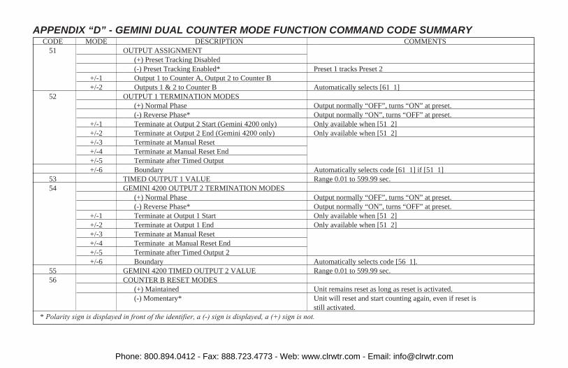
APPENDIX “D” - GEMINI DUAL COUNTER MODE FUNCTION COMMAND CODE SUMMARYCODE MODE DESCRIPTION COMMENTS
51 OUTPUT ASSIGNMENT
(+) Preset Tracking Disabled
(-) Preset Tracking Enabled* Preset 1 tracks Preset 2
+/-1 Output 1 to Counter A, Output 2 to Counter B
+/-2 Outputs 1 & 2 to Counter B Automatically selects [61 1]
52 OUTPUT 1 TERMINATION MODES
(+) Normal Phase Output normally “OFF”, turns “ON” at preset.
(-) Reverse Phase* Output normally “ON”, turns “OFF” at preset.
+/-1 Terminate at Output 2 Start (Gemini 4200 only) Only available when [51 2]
+/-2 Terminate at Output 2 End (Gemini 4200 only) Only available when [51 2]
+/-3 Terminate at Manual Reset
+/-4 Terminate at Manual Reset End
+/-5 Terminate after Timed Output
+/-6 Boundary Automatically selects code [61 1] if [51 1]
53 TIMED OUTPUT 1 VALUE Range 0.01 to 599.99 sec.
54 GEMINI 4200 OUTPUT 2 TERMINATION MODES
(+) Normal Phase Output normally “OFF”, turns “ON” at preset.
(-) Reverse Phase* Output normally “ON”, turns “OFF” at preset.
+/-1 Terminate at Output 1 Start Only available when [51 2]
+/-2 Terminate at Output 1 End Only available when [51 2]
+/-3 Terminate at Manual Reset
+/-4 Terminate at Manual Reset End
+/-5 Terminate after Timed Output 2
+/-6 Boundary Automatically selects code [56 1].
55 GEMINI 4200 TIMED OUTPUT 2 VALUE Range 0.01 to 599.99 sec.
56 COUNTER B RESET MODES
(+) Maintained Unit remains reset as long as reset is activated.
(-) Momentary* Unit will reset and start counting again, even if reset is
still activated.
* Polarity sign is displayed in front of the identifier, a (-) sign is displayed, a (+) sign is not.
Phone: 800.894.0412 - Fax: 888.723.4773 - Web: www.clrwtr.com - Email: [email protected]

APPENDIX “D” - GEMINI DUAL COUNTER MODE FUNCTION COMMAND CODE SUMMARY
CODE MODE DESCRIPTION COMMENTS
56 COUNTER B RESET MODES (Cont’d)
+/-1 Manual Reset to Zero Automatically selected when boundary mode is used [52,6].
+/-2 Manual Reset to Preset**
+/-3 Automatically Reset to Zero after Timed Output**
+/-4 Automatically Reset to Preset after Timed Output**
+/-5 Automatically Reset to Zero at Preset** Counter resets as soon as Output is activated.**
+/-6 Automatically Reset to Preset at Zero**
61 COUNTER A RESET MODES
(+) Maintained Unit remains reset as long as reset is activated.
(-) Momentary* Unit will reset and start counting again, even if reset is
still activated.
+/-1 Manual Reset to Zero Automatically selected when boundary mode is used [52,6].
+/-2 Manual Reset to Preset 1
+/-3 Automatically Reset to Zero after Timed Output 1
+/-4 Automatically Reset to Preset 1 after Timed Output 1
+/-5 Automatically Reset to Zero at Preset 1 Counter resets as soon as Output 1 is activated.
+/-6 Automatically Reset to Preset 1 at Zero
64 COUNTER A SCALE MULTIPLIER
1 1
2 0.1
3 0.01
4 0.001
* Polarity sign is displayed in front of the identifier, a (-) sign is displayed, a (+) sign is not.
** For the Gemini 4200, all reset to preset modes reset to preset 2 and Timed Output refers to Output 2.
Phone: 800.894.0412 - Fax: 888.723.4773 - Web: www.clrwtr.com - Email: [email protected]

APPENDIX “D” - GEMINI DUAL COUNTER MODE FUNCTION COMMAND CODE SUMMARYCODE MODE DESCRIPTION COMMENTS
65 CNTR A DECIMAL POINT & LEAD ZERO BLANKING
(+) Leading Zero Blanking Enabled
(-) Leading Zero Blanking Disabled*
+/-1 No Decimal Point
+/-2 Decimal Point Right of Digit 2
+/-3 Decimal Point Right of Digit 3
+/-4 Decimal Point Right of Digit 4
+/-5 Decimal Point Right of Digit 5
+/-6 Decimal Point Right of Digit 6
66 “OPERATOR ACCESSIBLE FUNCTIONS” MODES “PGM DIS” Terminal connected to “Comm”
(+) Reset Button & “RST” Terminal Enabled Front panel reset can be independently disabled by using
DIP switch.
(-) Reset Button & “RST” Terminal Disabled* This mode has no affect on the “RST A” terminal which is
always enabled.
+/-1 No Functions Enabled
+/-2 Preset Programming Enabled
+/-3 Scale Factor Programming Enabled
+/-4 Preset & Scale Factor Programming Enabled
+/-5 Preset & Counter Load Programming Enabled
+/-6 Preset, Scale Factor & Cnter Load Programming Enabled
1 PRESET 1 Up to +/-999999
2 PRESET 2 Up to +/-999999
3 Display A COUNTER A SCALE FACTOR Up to +/-5.9999
3 Display B COUNTER B SCALE FACTOR Up to +/-5.9999
E & Display A COUNTER A COUNTER LOAD VALUE Up to +/-999999. Counter Load value is NOT saved in
+/- memory when power is removed.
E & Display B COUNTER B COUNTER LOAD VALUE Up to +/-999999. Counter Load value is NOT saved in
+/- memory when power is removed.
* Polarity sign is displayed in front of the identifier, a (-) sign is displayed, a (+) sign is not.
Phone: 800.894.0412 - Fax: 888.723.4773 - Web: www.clrwtr.com - Email: [email protected]

APPENDIX “E” - SCALING FOR COUNTINGThe Gemini is factory set to provide 1 count on the display for each pulse that
is input to the unit. In many applications, there will not be a one to onecorrespondence between input pulses and display units. In these applications itwill be necessary for the Gemini to scale or multiply the input pulses by a scalingfactor to achieve the proper display units (feet, meters, gallons, widgets, etc.).There are three different function codes that are used in scaling the input pulses tothe desired reading. They are: the “Counter Scale Factor”, the “Counter ScaleMultiplier”, and the “Counter Number of Count Edges”. All three are factoredtogether to provide the Total Scaling that is necessary.
This section applies to Counter A (if Dual Counter personality) and Counter B.There are separate Scale Factors and Scale Multipliers associated with each counter.
The “Number of Count Edges”, function code 44 or code 43 (Quad x4), willapply to both counters. In other words, if one counter requires that 2 count edgesbe used per input pulse, programming that mode will cause both counters to useboth count edges. In the Quadrature x4, Inputs 1 & 2 Response mode, both therising and falling edges of both Inputs, 1 & 2, are counted. In this mode the“Number of Count Edges” is 4.
The first step in scaling the counter requires that the “Number of Pulses” per“Display Unit” or “Display Units” be obtained. This may require a small amountof deductive reasoning. For example: A 48 tooth gear is mounted to a 2 ftcircumference feed roll in a paper processing plant. It is desired to totalize thetotal footage of paper processed. In this example the units of display will be infeet. A sensor sensing the gear teeth will provide 48 pulses for each revolution ofthe feed roll. Each revolution will equate to a linear distance of 2 feet. Thenumber of “Display Units” will be 2. The “Number of Pulses” per “DisplayUnits” (2 feet) would naturally be 48.
Once the number of “Display Units” and the “Number of Pulses” have beenobtained, the Total Scaling Factor can be calculated.
The “Total Scaling Factor”, denoted as “KT”, is simply the total amount ofscaling required. It is obtained by dividing the “Display Units” by the “Numberof Pulses” as shown in Formula #1 below.
FORMULA #1: KT = Display Units/Number of Pulses
WHERE:DISPLAY UNITS - The number of units (revolutions, feet, 10ths of feet, meters,
etc.) that would be acquired after the “Number of Pulses” has occurred.
NUMBER OF PULSES - The Number of pulses required to achieve the numberof “Display Units”.
For the preceding example, the Total Scaling Factor, “KT”, is calculated byplugging in 2 and 48 in the formula. KT = Display Units/Number of Pulses = 2/48= 0.041667.
As previously stated, the Total Scaling Factor, “KT”, is the combination of theScale Factor, Scale Multiplier, and Number of Count edges. In many applications theTotal Scale Factor, “KT”, can be programmed directly into the Scale Factor, theScale Multiplier and Number of Count Edges factory settings, of x1, would be used.
In some applications, more display resolution may be required. Whenever theTotal Scaling Factor is greater than 1.0000 and when utilizing only one edge percount pulse, there may not be enough display resolution. For example; with aTotal Scaling Factor of 2.000, when an input pulse is generated, the display willincrement by 2. If the display units is in feet, when 3 feet has gone by, the displaywill still only read 2. It will not increment again until 4 feet has beenaccumulated. With this amount of display resolution it would be impossible to setthe Preset and have the output respond at odd feet intervals (1, 3, 5, etc.). Toincrease resolution, the Number of Count edges will have to be increased. Thiscan be achieved by programming Function code 44 to mode 2, 2 edges, orFunction code 43 to mode 6, Quad x4, if quadrature counting is being used.
If enough resolution still has not been attained, more input pulses will need tobe generated per display unit.
The amount of resolution required will vary depending on the particularapplication. In cut-to-length applications, a high amount of resolution is oftennecessary. However, in totalizing applications, display resolution may not beimportant. It should be noted that whenever the number of count edges isincreased to 2 or 4 (Quad x4), the maximum count frequency will decrease. (SeeAppendix “B” for maximum count frequency specification.)
Note: When using 2 or 4 edge counting for length sensor, on/off duty cycle mustbe 50% to maintain max. accuracy (mag. pickup will not work).
Phone: 800.894.0412 - Fax: 888.723.4773 - Web: www.clrwtr.com - Email: [email protected]

Once the Number of Count Edges (NCE) to be used has been determined, theRemaining Scaling factor required, “KR”, can be calculated. This is simply theTotal Scaling Factor, “KT”, divided by the Number of Count edges.
FORMULA #2: KR = KT/NCE
WHERE: KR - Remaining Scaling requiredIn our original example, the Total Scaling Factor, “KT” was determined to be
0.041667. Since this value is less than one, sufficient pulse information is beinggenerated, i.e., there is enough resolution for the units selected. The Number ofCount edges can be left at the factory set value of 1. The Total Scaling Factor,“KT”, effectively becomes the Total Scaling Remaining, “KR”. (KR = 0.041667/1= 0.041667)
If the scaling remaining is between 0.6000 and 5.9999, it can be programmeddirectly into the Scale Factor value and the x1 factory setting for the ScaleMultiplier, “SCM”, can be used.
The general rule for choosing an SCM value is, when the Remaining ScalingRequired, “KR”, is less than 0.6000, an SCM value of 0.1 or 0.01 can be used toget a Scale Factor value between 0.6 and 5.9999 or to the point where themaximum number of significant digits is obtained.
FORMULA #3: SF = KR/SCM
Following our continuing example, it is easy to see that the ScalingRemaining, “KR” (0.041667), cannot fit into the Scale Factor Value withoutlosing significant digits. Using the Formula above and a Scale Multiplier valueof 0.01, will allow us to get the maximum number of significant digits possible( SF = KR/SCM = 0.041667/0.01 = 4.1667).
COUNTER SCALING EXAMPLE:
EXAMPLE #1:
A flow sensor provides 62 pulses per gallon. Calculate the scaling required toprovide a display reading in gallons.
In this example the number of “Display Units” is the same as the desiredreading, since there are no decimal points involved.
The number of “Display Units” displayed after 62 pulses have been countedshould be 1.
STEP 1 - Calculate the Total Scaling Factor, “KT”, using Formula #1.
KT = Display Units/Number of Pulses (Formula #1)KT = 1/62 = 0.016129
STEP 2 - In this application 62 pulses per gallon provides more than enoughresolution, so the “Number of Count Edges” is left set to the factory configuredvalue of 1. With a “NCE” value of 1, the remaining amount of scaling necessaryis still 0.016129 KR = KT/NCE (Formula #2)
KR = 0.016129/1 = 0.016129
STEP 3 - In order to provide maximum scaling accuracy, a “Scale Multiplier”value is chosen that will give the maximum amount of significant digits in theScale Factor. A value of 0.01 will result in a Scale Factor Value of 1.6129.
SF = KR/SCM (Formula #3)SF = 0.016129/0.01 = 1.6129
EXAMPLE #2:
A quadrature Rotary Pulse Generator that provides 100 pulses per revolutionis coupled to a feed roll that is 2.5 feet in circumference. It is desired to read in feetwith display resolution to the nearest hundredth of feet.
In this application, the requirement is for the display to read in hundredths of afoot. A 2.5 ft. distance will equate to 250 “Display Units” (hundredths). The“Number of Pulses” for 2.5 ft. (250 hundredths) is 100, as stated.
From the information obtained, the Total Scaling Factor, “KT”, can becalculated, using Formula #1.
KT = Display Units/Number of PulsesKT = 250/100 = 2.5
With a Total Scaling Factor, “KT”, of 2.5, it can easily be seen that for everypulse that is input, the display will increment by 2.5 display units (hundredths).The application requires resolution to the nearest hundredth of a foot. In order toget higher resolution, Quadrature x4 Input Response Mode is selected. This willprovide four times more resolution. Using Formula #2, and 4 for the “Number ofCount Edges”, the Remaining Scaling, “KR”, is calculated.
KR = KT/Number of Count EdgesKR = 2.5/4 = 0.625
At this point, it can be seen that the Remaining Scaling value of 0.625 will fitinto the Scale Factor value range without losing any significant digits or scalingit any further. Because of this, the Scale Multiplier (SCM) factory set value of x1is used, and 0.6250 is programmed directly into the Scale Factor, “SF”.
SF = KR/SCMSF = 0.6250/1 = 0.6250
Phone: 800.894.0412 - Fax: 888.723.4773 - Web: www.clrwtr.com - Email: [email protected]

APPENDIX “F” - SCALING FOR RATEThe Gemini offers a simplified method for scaling the rate indicator. The
method does not require time unit conversions. The desired time format (Rate PerSecond, Rate Per Minute, Rate Per Hour) is simply selected as part of theprogramming procedure.
Due to the way the rate is calculated (See “General Description” section), highresolution and accuracy can be realized at all input rates, slow or fast. It is notnecessary to increase the pulse information to obtain higher resolution.
The Rate Minimum Update Time, function code 63, can be increased (from0.5 sec. up to 16 sec.) to provide averaging in applications where the input pulsespacing is not stable. The Update time selected, however, will not affect thescaling in any manner.
Scaling the Rate channel simply involves programming the Gemini so thatpulse units inputted to the unit will be scaled to the desired display units(revolutions, feet, meters, etc.) in the desired time format (Rate Per Second, Rateper Minute, Rate Per Hour).
There are two basic types of rate scaling applications for the Gemini. The firstis when the rate indicator is to display the rate at which the counter is counting(count and rate using the same sensor). In this case, the rate indicator can beprogrammed with the same scaling parameters as the counter. The only otherrequirement is that the desired “Rate Conversion Factor”, function code 62, beselected to provide the rate display in the desired time format, i.e., Rate per Second,Rate per Minute or Rate per Hour. This will automatically scale the rate by x1, x60or x3600 (1 pulse per second = 60 pulses per minute = 3600 pulses per hour).Note: If the number of Count Edges for Counter B is 2 or 4, the rate must be
scaled by the same amount using the Rate Scale Factor and Scale Multiplier.This is due to the fact that the rate indicator only uses 1 edge.The second basic type of rate application is when the rate indicator and counter
are using two separate sensors. In this case, both the rate and count channels mustbe scaled separately.
Scaling for the count channel is discussed in Appendix “E” - Scaling forCounter.
In order to scale the rate, it is only necessary to know the number of pulses perdisplay unit or units (feet, revolutions, etc.). For example; if a 48 tooth gear,which is coupled to a shaft, is being sensed and it is desired to indicate the shaftspeed in revolutions, the display units would be revolutions. It is obvious that 48pulses will occur in one revolution.
In order to convert the pulse units to revolutions, it is necessary for the Geminito multiply the number of pulses by a scaling factor to convert the pulse units torevolution units. The Gemini has two programming codes that serve to scalepulse units to desired display units. They are: the Scale Factor and the ScaleMultiplier. Both are used to attain the Total Scaling Factor, “KT”.
To calculate the Total Scaling Factor, “KT”, for the application, the followingformula is used.
FORMULA #1: KT = Display units/Number of pulses
WHERE:DISPLAY UNITS - The number of units (revolutions, feet, 10ths of feet, meters,
etc.) that would be acquired after the “Number of Pulses” has occurred.
NUMBER OF PULSES - The Number of pulses required to achieve the numberof “Display Units”.
Using the example previously discussed, the display unit would be 1revolution and the number of pulses per display unit would be 48. Therefore, theTotal Scale Factor would be 0.020833 (KT = Display Units/Number of Pulses = 1rev/48 pulses per rev = 0.020833). In many applications the Total Scale Factor,“KT”, can be programmed as the Scale Factor, “SF”, and the Scale Multiplier,“SCM”, factory setting, x1, would be used. However, in some applications, suchas the one above, it may be desired to obtain more significant digits in the ScaleFactor, “SF”.
These situations occur when the “KT” factor does not calculate to an evennumber that will be fit into the four decimal places available to the Scale Factor.The following formula can be used to calculate the Scale Factor when an SCMvalue other than x1 is needed.
FORMULA #2: SF = KT/SCM
In this formula, the Total Scaling Factor, previously calculated, is divided bythe Scale Multiplier Value, “SCM”, to obtain the Scale Factor, “SF”.
The general rule for choosing an SCM value is, when the Total Scale Factor,“KT”, is less than 0.6000, an SCM value of 0.1 or 0.01 can be used to get a ScaleFactor value between 0.6 and 5.9999, or to the point where the maximum numberof significant digits is obtained. If the Total Scaling Factor, “KT”, is greater than5.9999, then an SCM value of 10, 100, or 1000 can be used to obtain a ScaleFactor Value between 0.6 and 5.9999.
In our initial example, the Total Scaling Factor, “KT” was determined to be0.020833. It is easy to see that this number cannot be programmed into the ScaleFactor, “SF”, without losing significant digits. Using formula #2 and the general
Phone: 800.894.0412 - Fax: 888.723.4773 - Web: www.clrwtr.com - Email: [email protected]

rules stated above, a Scale Multiplier Value of 0.01 is chosen and the Scale Factoris calculated as shown below. This will provide maximum amount of conversionaccuracy possible. SF = KT/SCM
SF = 0.020833/SCMSF = 0.020833/0.01 = 2.0833
In situations where the Total Scale Factor is already in range of the ScaleFactor (0.0001 to 5.9999) and when there are no significant digits that are lost,the Total Scaling Factor, “KT”, can be programmed directly into the Scale FactorValue and a Scale Multiplier value of 1 (the factory set value) used. For example;if the display units are in feet and there are 100 pulses per foot, the Total ScalingFactor, “KT”, would be 0.01 ( KT = Display units/pulses per display units = 1 / 100= 0.01). Since the Total Scaling Factor, “KT”, is exactly 0.01, it can beprogrammed into the Scale Factor Value, “SF”, and the Scale Multiplier Value,“SCM”, can be left at, or programmed to, its factory setting of x1.
After the Scale Factor and Scale Multiplier values are selected, all that isnecessary to complete the scaling is to choose the Rate Conversion Factor. TheRate Conversion Factor can be selected to provide indication in Rate per Second,Rate Per Minute, or Rate per Hour.Note: There may be situations where there are many more pulses per display unit
than needed. In these situations the minimum SCM value (0.01) may notprovide enough significant digits in the Scale Factor. To achieve moresignificant digits, the Rate Conversion Factor should be set to mode 1, Rateper Second and the following formula be used.
SF = KT x CFSCM
Where: CF = 60 for display reading in Rate Per Minute, orCF = 3600 for display reading in Rate Per Hour
RATE SCALING EXAMPLE:
EXAMPLE #1:
A 60 tooth gear is mounted to a roll that has a circumference of 2 feet. It isdesired to have a rate readout in 10ths of feet per minute. Calculate the ScaleFactor and Scale Multiplier values necessary to provide the desired readout.
In this example one revolution of the web will provide 60 pulses for 2 feet oflinear travel. Since the desired display units are to be in tenths of feet, it isnecessary to convert 2 feet to tenths, giving us 20 tenths (display units). TheTotal Scaling Factor, “KT”, is calculated by simply plugging in the twonumbers into formula #1.
KT = Display Units/Number of PulsesKT = 20/60 = 0.333333
In order to get the maximum number of significant digits in the Scale Factorwe use formula #2 and a Scale Multiplier value of 0.1 as shown below.
SF = KT/SCM SF = 0.333333/0.1 = 3.3333
To obtain rate indication in Feet Per Minute, the Rate Conversion Factor isprogrammed for Rate per Minute mode. A decimal point is also added to providefor a display of feet in 10ths.
EXAMPLE #2:
The shaft of a positive displacement pump has a 14 tooth sprocket that is beingsensed by a magnetic pickup. It is known that when the unit is pumping 810 litersof water per minute, the shaft is turning 400 RPM. It is desired to have a displayreadout in liters per minute.
With the Gemini, it is not necessary to deal with time unit conversions. Fromthe information given, we know that when the shaft has turned 400 revolutions,810 liters of water will have been pumped. The first step we need to take, is tocalculate the number of pulses that occur when 810 liters have been pumped.
NUMBER OF PULSES = # of Revolutions x Pulses per Rev.
NUMBER OF PULSES = 400 Rev x 14 Pulses per Rev = 5600 pulses.
We now have all the information necessary to scale the rate. The Total ScalingFactor, “KT”, is calculated using Formula #1 as shown below.
KT = Display Units/Number of PulsesKT = 810/5600 = 0.144643
It is noticed that there are more significant digits in the Total Scale Factor,“KT”, than there are available for the Scale Factor, “SF”. In order to acquire themaximum amount of significant digits for the Scale Factor, Formula #2 is usedand a Scale Multiplier value of 0.1 is selected.
SF = KT/SCMSF = 0.144643/0.1 = 1.4464
The Scale Factor, “SF”, then becomes 1.4464 (1.44643 rounded to 4 decimalplaces). This provides the maximum amount of conversion accuracy possible.
The final step is to select a Rate Conversion Factor. The Rate ConversionFactor is chosen to be Rate Per Minute as was required.
Phone: 800.894.0412 - Fax: 888.723.4773 - Web: www.clrwtr.com - Email: [email protected]

Phone: 800.894.0412 - Fax: 888.723.4773 - Web: www.clrwtr.com - Email: [email protected]
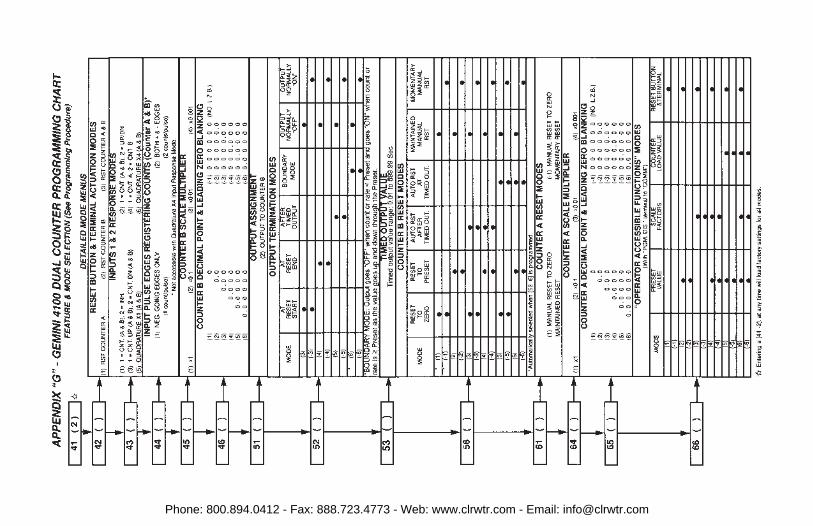
Phone: 800.894.0412 - Fax: 888.723.4773 - Web: www.clrwtr.com - Email: [email protected]

Phone: 800.894.0412 - Fax: 888.723.4773 - Web: www.clrwtr.com - Email: [email protected]

Phone: 800.894.0412 - Fax: 888.723.4773 - Web: www.clrwtr.com - Email: [email protected]

Phone: 800.894.0412 - Fax: 888.723.4773 - Web: www.clrwtr.com - Email: [email protected]

Phone: 800.894.0412 - Fax: 888.723.4773 - Web: www.clrwtr.com - Email: [email protected]

Phone: 800.894.0412 - Fax: 888.723.4773 - Web: www.clrwtr.com - Email: [email protected]

Phone: 800.894.0412 - Fax: 888.723.4773 - Web: www.clrwtr.com - Email: [email protected]

MODELNO.
DESCRIPTIONW/20 mA
Current Loop
PART NUMBERS
115/230 VAC
GEM41 Gemini 4100No GEM41060
Yes GEM41160
GEM42 Gemini 4200No GEM42060
Yes GEM42160
Gemini 4100 Relay Board RLYBD001
Gemini 4200 Relay Board RLYBD002
For Information on Pricing, Enclosures & Panel Mount Kits, refer to the RLCCatalog or contact your local RLC distributor.
APPENDIX “I” - ORDERING INFORMATION
Phone: 800.894.0412 - Fax: 888.723.4773 - Web: www.clrwtr.com - Email: [email protected]

LIMITED WARRANTYThe Company warrants the products it manufactures against defects inmaterials and workmanship for a period limited to two years from the date ofshipment, provided the products have been stored, handled, installed, and usedunder proper conditions. The Company’s liability under this limited warrantyshall extend only to the repair or replacement of a defective product, at TheCompany’s option. The Company disclaims all liability for any affirmation,promise or representation with respect to the products.
The customer agrees to hold Red Lion Controls harmless from, defend, andindemnify RLC against damages, claims, and expenses arising out ofsubsequent sales of RLC products or products containing componentsmanufactured by RLC and based upon personal injuries, deaths, propertydamage, lost profits, and other matters which Buyer, its employees, or sub-contractors are or may be to any extent liable, including without limitationpenalties imposed by the Consumer Product Safety Act (P.L. 92-573) andliability imposed upon any person pursuant to the Magnuson-Moss WarrantyAct (P.L. 93-637), as now in effect or as amended hereafter.
No warranties expressed or implied are created with respect to The Company’sproducts except those expressly contained herein. The Customer acknowledgesthe disclaimers and limitations contained and relies on no other warranties oraffirmations.
Phone: 800.894.0412 - Fax: 888.723.4773 - Web: www.clrwtr.com - Email: [email protected]