the atn sarps - telaga.cs.ui.ac.idtelaga.cs.ui.ac.id/~fahmi/atn_iso_icao/icao_sarps_ed3vol5.pdf ·...
TRANSCRIPT

The ATN SARPs
Subvolume Five
Internet Communications Service (ICS) Third Edition
(Final Editor’s Draft)
Please note that this is the final editor’s draft of the “Manual of Technical Provisions for the Aeronautical Telecommunication Network (ATN) – ICAO DOC 9705/AN956 - as circulated
within the ATNP. This text will be passed to ICAO for publication. However, it should be noted that this text in no way replaces the ICAO version, nor can it be considered to be of equal
status. The official definitive version is that published in hardcopy by ICAO and all claims of compliance must be made against that version.
This PDF version has been prepared for the ATNP Working Groups by Helios Information Services Ltd. – http://www.helios-is.com
Please check our web site regularly for updates to the draft SARPs

Errata and Disclaimer
Please note that this document has been prepared from a number of separate files and no attempt has been made to ensure continuity of page numbers. You may therefore find some overlap between page numbers. This document has been prepared on a “best efforts” basis and no warrantee is offered as to its correctness.
(iii)
FOREWORD
The material contained in this document was originally developed as the detailed part of thefirst set of Standards and Recommended Practices (SARPs) for the aeronautical telecommunication network(ATN) which has commonly been referred to as the CNS/ATM-1 Package. It was intended to make thematerial an appendix to the new Chapter 3 of Annex 10, Volume III, Part I, containing broad, general, stableand mostly regulatory-type provisions (the core part of new ATN SARPs).
In December 1997, the Air Navigation Commission (ANC), while conducting the final reviewof draft ATN SARPs, agreed that the detailed part of ATN SARPs should be published as an ICAO manual(to be updated annually, if necessary), while retaining its SARPs-style language. The ANC has reviewed thestatus of the document in light of continuing worldwide ATN implementation. The Third Edition includesamendments from implementors and regulatory authorities, as well as four new Sub-Volumes to answerrequirements for further standardization, in the interests of safety, regularity and efficiency of international civilaviation.
This document consists of nine Sub-Volumes:
Sub-Volume I — Introduction and System Level RequirementsSub-Volume II — Air-Ground ApplicationsSub-Volume III — Ground-Ground ApplicationsSub-Volume IV — Upper Layer Communications Service (ULCS)Sub-Volume V — Internet Communications Service (ICS)Sub-Volume VI — System Management (SM)Sub-Volume VII — Directory Services (DIR)Sub-Volume VIII — Security (SEC)Sub-Volume IX — Registration (REG)
Provisions contained in Sub-Volumes II, III, IV, V, VI, VII, VIII, and IX have been developed in accordancewith system requirements specified in Sub-Volume I.
In line with the agreement by the ANC that the document should be updated on a yearly basis (if deemednecessary), the Third Edition has been published to incorporate changes necessitated by continuing validationand actual implementation activities.

(v)
TABLE OF CONTENTS
SUB-VOLUME I. INTRODUCTION AND SYSTEM LEVEL REQUIREMENTS
1.1 Definitions and References . . . . . . . . . . . . . . . . . . . . . . . . . . . . . . . . . . . . . . . . . . . . . . . . . . . I-11.1.1 Definitions . . . . . . . . . . . . . . . . . . . . . . . . . . . . . . . . . . . . . . . . . . . . . . . . . . . . . . . . . I-11.1.2 References . . . . . . . . . . . . . . . . . . . . . . . . . . . . . . . . . . . . . . . . . . . . . . . . . . . . . . . . I-24
1.2 General . . . . . . . . . . . . . . . . . . . . . . . . . . . . . . . . . . . . . . . . . . . . . . . . . . . . . . . . . . . . . . . . . I-37
1.3 System Level Requirements . . . . . . . . . . . . . . . . . . . . . . . . . . . . . . . . . . . . . . . . . . . . . . . . . . I-39
SUB-VOLUME II. AIR-GROUND APPLICATIONS
2.1 Context Management Application . . . . . . . . . . . . . . . . . . . . . . . . . . . . . . . . . . . . . . . . . . . . .II-12.1.1 Introduction . . . . . . . . . . . . . . . . . . . . . . . . . . . . . . . . . . . . . . . . . . . . . . . . . . . . . . .II-12.1.2 General Requirements . . . . . . . . . . . . . . . . . . . . . . . . . . . . . . . . . . . . . . . . . . . . . . . .II-72.1.3 The Abstract Service . . . . . . . . . . . . . . . . . . . . . . . . . . . . . . . . . . . . . . . . . . . . . . . . .II-82.1.4 Formal Definitions of Messages . . . . . . . . . . . . . . . . . . . . . . . . . . . . . . . . . . . . . . .II-312.1.5 Protocol Definition . . . . . . . . . . . . . . . . . . . . . . . . . . . . . . . . . . . . . . . . . . . . . . . . .II-382.1.6 Communication Requirements . . . . . . . . . . . . . . . . . . . . . . . . . . . . . . . . . . . . . . . .II-1072.1.7 CM User Requirements . . . . . . . . . . . . . . . . . . . . . . . . . . . . . . . . . . . . . . . . . . . . .II-1092.1.8 Subsetting Rules . . . . . . . . . . . . . . . . . . . . . . . . . . . . . . . . . . . . . . . . . . . . . . . . . .II-123
2.2 Automatic Dependent Surveillance Applications. . . . . . . . . . . . . . . . . . . . . . . . . . . . . . . .II-1262.2.1 Automatic Dependent Surveillance Application. . . . . . . . . . . . . . . . . . . . . . . . . . .II-1262.2.2 Automatic Dependent Surveillance Report Forwarding
Application . . . . . . . . . . . . . . . . . . . . . . . . . . . . . . . . . . . . . . . . . . . . . . . . . . . . . .II-264
2.3 Controller Pilot Data Link Communication Application . . . . . . . . . . . . . . . . . . . . . . . . . . .II-2962.3.1 Introduction . . . . . . . . . . . . . . . . . . . . . . . . . . . . . . . . . . . . . . . . . . . . . . . . . . . . .II-2962.3.2 General Requirements . . . . . . . . . . . . . . . . . . . . . . . . . . . . . . . . . . . . . . . . . . . . . .II-2982.3.3 The Abstract Service . . . . . . . . . . . . . . . . . . . . . . . . . . . . . . . . . . . . . . . . . . . . . . .II-2992.3.4 Formal Definitions of Messages . . . . . . . . . . . . . . . . . . . . . . . . . . . . . . . . . . . . . .II-3132.3.5 Protocol Definition . . . . . . . . . . . . . . . . . . . . . . . . . . . . . . . . . . . . . . . . . . . . . . . .II-3632.3.6 Communication Requirements . . . . . . . . . . . . . . . . . . . . . . . . . . . . . . . . . . . . . . . .II-4192.3.7 CPDLC User Requirements . . . . . . . . . . . . . . . . . . . . . . . . . . . . . . . . . . . . . . . . .II-4202.3.8 Subsetting Rules . . . . . . . . . . . . . . . . . . . . . . . . . . . . . . . . . . . . . . . . . . . . . . . . .II-477
2.4 Flight Information Services Application . . . . . . . . . . . . . . . . . . . . . . . . . . . . . . . . . . . . . . .II-4812.4.1 Introduction . . . . . . . . . . . . . . . . . . . . . . . . . . . . . . . . . . . . . . . . . . . . . . . . . . . . .II-4812.4.2 General Requirements . . . . . . . . . . . . . . . . . . . . . . . . . . . . . . . . . . . . . . . . . . . . . .II-4882.4.3 The Abstract Service . . . . . . . . . . . . . . . . . . . . . . . . . . . . . . . . . . . . . . . . . . . . . . .II-4892.4.4 Formal Definitions of Messages . . . . . . . . . . . . . . . . . . . . . . . . . . . . . . . . . . . . . .II-5002.4.5 Protocol Definition . . . . . . . . . . . . . . . . . . . . . . . . . . . . . . . . . . . . . . . . . . . . . . . .II-5422.4.6 Communication Requirements . . . . . . . . . . . . . . . . . . . . . . . . . . . . . . . . . . . . . . . .II-594

(vi) Manual of Technical Provisions for the Aeronautical Telecommunication Network (ATN)
2.4.7 FIS User Requirements . . . . . . . . . . . . . . . . . . . . . . . . . . . . . . . . . . . . . . . . . . . . .II-5952.4.8 Subsetting Rules . . . . . . . . . . . . . . . . . . . . . . . . . . . . . . . . . . . . . . . . . . . . . . . . .II-602
SUB-VOLUME III. GROUND-GROUND APPLICATIONS
3.1 ATS Message Handling Services (ATSMHS) . . . . . . . . . . . . . . . . . . . . . . . . . . . . . . . . . . .III-13.1.1 Introduction . . . . . . . . . . . . . . . . . . . . . . . . . . . . . . . . . . . . . . . . . . . . . . . . . . . . . .III-13.1.2 ATS Message Service . . . . . . . . . . . . . . . . . . . . . . . . . . . . . . . . . . . . . . . . . . . . . . .III-7
3.2 ATS Interfacility Data Communications. . . . . . . . . . . . . . . . . . . . . . . . . . . . . . . . . . . . .III-3273.2.1 Introduction . . . . . . . . . . . . . . . . . . . . . . . . . . . . . . . . . . . . . . . . . . . . . . . . . . . .III-3273.2.2 General Requirements . . . . . . . . . . . . . . . . . . . . . . . . . . . . . . . . . . . . . . . . . . . . .III-3313.2.3 The AIDC-AE Abstract Service . . . . . . . . . . . . . . . . . . . . . . . . . . . . . . . . . . . . .III-3323.2.4 The AIDC-ASE Abstract Service . . . . . . . . . . . . . . . . . . . . . . . . . . . . . . . . . . . .III-3473.2.5 The AIDC Control Function . . . . . . . . . . . . . . . . . . . . . . . . . . . . . . . . . . . . . . . .III-3583.2.6 The AIDC-ASE Protocol Definition . . . . . . . . . . . . . . . . . . . . . . . . . . . . . . . . . .III-3893.2.7 AIDC Formal Definitions . . . . . . . . . . . . . . . . . . . . . . . . . . . . . . . . . . . . . . . . . .III-4283.2.8 Communication Requirements . . . . . . . . . . . . . . . . . . . . . . . . . . . . . . . . . . . . . . .III-4513.2.9 AIDC-user Requirements . . . . . . . . . . . . . . . . . . . . . . . . . . . . . . . . . . . . . . . . . .III-4523.2.10 Sequence Diagrams . . . . . . . . . . . . . . . . . . . . . . . . . . . . . . . . . . . . . . . . . . . . . . .III-455
SUB-VOLUME IV. UPPER LAYER COMMUNICATIONS SERVICE
4.1 INTRODUCTION . . . . . . . . . . . . . . . . . . . . . . . . . . . . . . . . . . . . . . . . . . . . . . . . . . . . . . . . . . IV-14.1.1 Scope and Objectives . . . . . . . . . . . . . . . . . . . . . . . . . . . . . . . . . . . . . . . . . . . . . . . . . IV-14.1.2 Background . . . . . . . . . . . . . . . . . . . . . . . . . . . . . . . . . . . . . . . . . . . . . . . . . . . . . . . . IV-24.1.3 Structure of UL Communications Service Specification . . . . . . . . . . . . . . . . . . . . . . . IV-34.1.4 Upper Layer Functionality . . . . . . . . . . . . . . . . . . . . . . . . . . . . . . . . . . . . . . . . . . . . . IV-44.1.5 Conventions. . . . . . . . . . . . . . . . . . . . . . . . . . . . . . . . . . . . . . . . . . . . . . . . . . . . . . . . IV-6
4.2 DIALOGUE SERVICE DESCRIPTION . . . . . . . . . . . . . . . . . . . . . . . . . . . . . . . . . . . . . . . . . IV-74.2.1 Scope of Dialogue Service . . . . . . . . . . . . . . . . . . . . . . . . . . . . . . . . . . . . . . . . . . . IV-74.2.2 Service Primitives . . . . . . . . . . . . . . . . . . . . . . . . . . . . . . . . . . . . . . . . . . . . . . . . . . . IV-84.2.3 Service Definition . . . . . . . . . . . . . . . . . . . . . . . . . . . . . . . . . . . . . . . . . . . . . . . . . . . IV-9
4.3 APPLICATION ENTITY (AE) DESCRIPTION . . . . . . . . . . . . . . . . . . . . . . . . . . . . . . . . . . IV-184.3.1 Introduction . . . . . . . . . . . . . . . . . . . . . . . . . . . . . . . . . . . . . . . . . . . . . . . . . . . . . . . IV-184.3.2 Application Level Naming and Context Definition . . . . . . . . . . . . . . . . . . . . . . . . . . IV-204.3.3 Control Function Specification . . . . . . . . . . . . . . . . . . . . . . . . . . . . . . . . . . . . . . . . . IV-29
4.4 SESSION LAYER REQUIREMENTS . . . . . . . . . . . . . . . . . . . . . . . . . . . . . . . . . . . . . . . . . . IV-934.4.1 Protocol versions implemented . . . . . . . . . . . . . . . . . . . . . . . . . . . . . . . . . . . . . . . . . IV-944.4.2 Session Functional units . . . . . . . . . . . . . . . . . . . . . . . . . . . . . . . . . . . . . . . . . . . . . IV-954.4.3 Protocol mechanisms . . . . . . . . . . . . . . . . . . . . . . . . . . . . . . . . . . . . . . . . . . . . . . . . IV-974.4.4 Supported Roles. . . . . . . . . . . . . . . . . . . . . . . . . . . . . . . . . . . . . . . . . . . . . . . . . . . IV-99

Table of Contents (vii)
4.4.5 Supported SPDUs. . . . . . . . . . . . . . . . . . . . . . . . . . . . . . . . . . . . . . . . . . . . . . . . . IV-1014.4.6 Use of null-encoding and short-connect protocol options. . . . . . . . . . . . . . . . . . . . . IV-1044.4.7 Mapping to the ATN Internet Transport Service . . . . . . . . . . . . . . . . . . . . . . . . . . . IV-105
4.5 PRESENTATION LAYER REQUIREMENTS . . . . . . . . . . . . . . . . . . . . . . . . . . . . . . . . . . IV-1074.5.1 Protocol mechanisms . . . . . . . . . . . . . . . . . . . . . . . . . . . . . . . . . . . . . . . . . . . . . . . IV-1084.5.2 Use of null-encoding and short-connect protocol options. . . . . . . . . . . . . . . . . . . . . IV-1094.5.3 Mapping of Presentation Primitives to the Null Encoding option . . . . . . . . . . . . . . . IV-1104.5.4 Functional units . . . . . . . . . . . . . . . . . . . . . . . . . . . . . . . . . . . . . . . . . . . . . . . . . . . IV-1114.5.5 Elements of procedure . . . . . . . . . . . . . . . . . . . . . . . . . . . . . . . . . . . . . . . . . . . . . . IV-1134.5.6 Supported Presentation Protocol Data Units (PPDUs). . . . . . . . . . . . . . . . . . . . . . IV-115
4.6 ACSE SPECIFICATION . . . . . . . . . . . . . . . . . . . . . . . . . . . . . . . . . . . . . . . . . . . . . . . . . . . IV-1174.6.1 Protocol details . . . . . . . . . . . . . . . . . . . . . . . . . . . . . . . . . . . . . . . . . . . . . . . . . . . IV-1174.6.2 Protocol versions . . . . . . . . . . . . . . . . . . . . . . . . . . . . . . . . . . . . . . . . . . . . . . . . . . IV-1184.6.3 Supported roles. . . . . . . . . . . . . . . . . . . . . . . . . . . . . . . . . . . . . . . . . . . . . . . . . . . IV-1194.6.4 Protocol mechanisms . . . . . . . . . . . . . . . . . . . . . . . . . . . . . . . . . . . . . . . . . . . . . . . IV-1214.6.5 ACSE Functional units . . . . . . . . . . . . . . . . . . . . . . . . . . . . . . . . . . . . . . . . . . . . . IV-1224.6.6 Supported APDUs. . . . . . . . . . . . . . . . . . . . . . . . . . . . . . . . . . . . . . . . . . . . . . . . . IV-1234.6.7 Mapping to the Presentation Service . . . . . . . . . . . . . . . . . . . . . . . . . . . . . . . . . . . IV-130
4.7 CONNECTIONLESS DIALOGUE SERVICE AND PROFILE. . . . . . . . . . . . . . . . . . . . . . IV-1314.7.1 Scope of Connectionless Dialogue Service. . . . . . . . . . . . . . . . . . . . . . . . . . . . . . . IV-1314.7.2 Service Primitives . . . . . . . . . . . . . . . . . . . . . . . . . . . . . . . . . . . . . . . . . . . . . . . . . IV-1324.7.3 The D-UNIT-DATA service . . . . . . . . . . . . . . . . . . . . . . . . . . . . . . . . . . . . . . . . . IV-1334.7.4 Control Function for the Connectionless Mode Dialogue Service. . . . . . . . . . . . . . IV-1364.7.5 Subsetting Rules . . . . . . . . . . . . . . . . . . . . . . . . . . . . . . . . . . . . . . . . . . . . . . . . . . IV-1434.7.6 APRL for Connectionless Session Protocol. . . . . . . . . . . . . . . . . . . . . . . . . . . . . . IV-1444.7.7 APRL for Connectionless Presentation Protocol. . . . . . . . . . . . . . . . . . . . . . . . . . . IV-1464.7.8 APRL for Connectionless ACSE Protocol. . . . . . . . . . . . . . . . . . . . . . . . . . . . . . . IV-148
4.8 SECURITY APPLICATION SERVICE OBJECT . . . . . . . . . . . . . . . . . . . . . . . . . . . . . . . . IV-1524.8.1 Scope and Structure . . . . . . . . . . . . . . . . . . . . . . . . . . . . . . . . . . . . . . . . . . . . . . . . IV-1524.8.2 General Requirements . . . . . . . . . . . . . . . . . . . . . . . . . . . . . . . . . . . . . . . . . . . . . . IV-1554.8.3 The SA Abstract Service . . . . . . . . . . . . . . . . . . . . . . . . . . . . . . . . . . . . . . . . . . . . IV-1564.8.4 Formal Definition of Messages . . . . . . . . . . . . . . . . . . . . . . . . . . . . . . . . . . . . . . . IV-1604.8.5 Definition of the Security ASO Control Function (SA-CF) . . . . . . . . . . . . . . . . . . . IV-1634.8.6 SESE Profile Requirements . . . . . . . . . . . . . . . . . . . . . . . . . . . . . . . . . . . . . . . . . . IV-173
4.9 GENERIC ATN COMMUNICATIONS SERVICE SPECIFICATION . . . . . . . . . . . . . . . . . IV-1804.9.1 Scope and Structure . . . . . . . . . . . . . . . . . . . . . . . . . . . . . . . . . . . . . . . . . . . . . . . . IV-1804.9.2 GACS Service Definition . . . . . . . . . . . . . . . . . . . . . . . . . . . . . . . . . . . . . . . . . . . . IV-1854.9.3 Protocol Definition . . . . . . . . . . . . . . . . . . . . . . . . . . . . . . . . . . . . . . . . . . . . . . . . IV-1944.9.4 Communication Requirements . . . . . . . . . . . . . . . . . . . . . . . . . . . . . . . . . . . . . . . . IV-2304.9.5 User Requirements . . . . . . . . . . . . . . . . . . . . . . . . . . . . . . . . . . . . . . . . . . . . . . . . IV-2324.9.6 Subsetting Rules . . . . . . . . . . . . . . . . . . . . . . . . . . . . . . . . . . . . . . . . . . . . . . . . . . IV-233

(viii) Manual of Technical Provisions for the Aeronautical Telecommunication Network (ATN)
SUB-VOLUME V. INTERNET COMMUNICATIONS SERVICE
5.1 Introduction . . . . . . . . . . . . . . . . . . . . . . . . . . . . . . . . . . . . . . . . . . . . . . . . . . . . . . . . . . . . . . V-1
5.2 Definitions and Concepts . . . . . . . . . . . . . . . . . . . . . . . . . . . . . . . . . . . . . . . . . . . . . . . . . . . . V-25.2.1 Objectives and Goals . . . . . . . . . . . . . . . . . . . . . . . . . . . . . . . . . . . . . . . . . . . . . . . . V-25.2.2 Definitions . . . . . . . . . . . . . . . . . . . . . . . . . . . . . . . . . . . . . . . . . . . . . . . . . . . . . . . . V-35.2.3 ATN End Systems . . . . . . . . . . . . . . . . . . . . . . . . . . . . . . . . . . . . . . . . . . . . . . . . . . V-85.2.4 ATN Routers . . . . . . . . . . . . . . . . . . . . . . . . . . . . . . . . . . . . . . . . . . . . . . . . . . . . . V-105.2.5 ATN Subnetworks . . . . . . . . . . . . . . . . . . . . . . . . . . . . . . . . . . . . . . . . . . . . . . . . . V-135.2.6 Quality of Service Concept . . . . . . . . . . . . . . . . . . . . . . . . . . . . . . . . . . . . . . . . . . . V-165.2.7 ATN Security Concept . . . . . . . . . . . . . . . . . . . . . . . . . . . . . . . . . . . . . . . . . . . . . . V-175.2.8 ATN Use of Priority . . . . . . . . . . . . . . . . . . . . . . . . . . . . . . . . . . . . . . . . . . . . . . . . V-23
5.3 ATN Routing . . . . . . . . . . . . . . . . . . . . . . . . . . . . . . . . . . . . . . . . . . . . . . . . . . . . . . . . . . . V-285.3.1 Introduction . . . . . . . . . . . . . . . . . . . . . . . . . . . . . . . . . . . . . . . . . . . . . . . . . . . . . . V-285.3.2 Service Provided by an ATN Router . . . . . . . . . . . . . . . . . . . . . . . . . . . . . . . . . . . . V-305.3.3 The Deployment of ATN Components . . . . . . . . . . . . . . . . . . . . . . . . . . . . . . . . . . . V-385.3.4 Ground/Ground Interconnection. . . . . . . . . . . . . . . . . . . . . . . . . . . . . . . . . . . . . . . V-405.3.5 Air/Ground Interconnection. . . . . . . . . . . . . . . . . . . . . . . . . . . . . . . . . . . . . . . . . . . V-435.3.6 Handling Routing Information . . . . . . . . . . . . . . . . . . . . . . . . . . . . . . . . . . . . . . . . . V-695.3.7 Policy Based Selection of Routes for Advertisement to Adjacent RDs . . . . . . . . . . . V-70
5.4 Network and Transport Addressing Specification . . . . . . . . . . . . . . . . . . . . . . . . . . . . . . . . . V-785.4.1 Introduction . . . . . . . . . . . . . . . . . . . . . . . . . . . . . . . . . . . . . . . . . . . . . . . . . . . . . . V-785.4.2 Transport Layer Addressing . . . . . . . . . . . . . . . . . . . . . . . . . . . . . . . . . . . . . . . . . . V-795.4.3 Network Layer Addressing . . . . . . . . . . . . . . . . . . . . . . . . . . . . . . . . . . . . . . . . . . . V-81
5.5 Transport Service and Protocol Specification . . . . . . . . . . . . . . . . . . . . . . . . . . . . . . . . . . . . V-955.5.1 General . . . . . . . . . . . . . . . . . . . . . . . . . . . . . . . . . . . . . . . . . . . . . . . . . . . . . . . . . . V-955.5.2 Connection Mode Transport Layer Operation. . . . . . . . . . . . . . . . . . . . . . . . . . . . . V-985.5.3 Connectionless Mode Transport Protocol Operation. . . . . . . . . . . . . . . . . . . . . . . V-1255.5.4 Extended 32-bit Checksum . . . . . . . . . . . . . . . . . . . . . . . . . . . . . . . . . . . . . . . . . V-129
5.6 Internetwork Service and Protocol Specification . . . . . . . . . . . . . . . . . . . . . . . . . . . . . . . . . V-1345.6.1 Introduction . . . . . . . . . . . . . . . . . . . . . . . . . . . . . . . . . . . . . . . . . . . . . . . . . . . . . V-1345.6.2 ATN Specific Features . . . . . . . . . . . . . . . . . . . . . . . . . . . . . . . . . . . . . . . . . . . . . V-1355.6.3 ATN Specific Requirements for ISO/IEC 8473. . . . . . . . . . . . . . . . . . . . . . . . . . . V-1425.6.4 APRLs . . . . . . . . . . . . . . . . . . . . . . . . . . . . . . . . . . . . . . . . . . . . . . . . . . . . . . . . . V-144
5.7 Specification of Subnetwork Dependent Convergence Functions. . . . . . . . . . . . . . . . . . . . . V-1665.7.1 Introduction . . . . . . . . . . . . . . . . . . . . . . . . . . . . . . . . . . . . . . . . . . . . . . . . . . . . . V-1665.7.2 Service Provided by the SNDCF . . . . . . . . . . . . . . . . . . . . . . . . . . . . . . . . . . . . . . V-1675.7.3 SNDCF for ISO/IEC 8802-2 Broadcast Subnetworks. . . . . . . . . . . . . . . . . . . . . . V-1695.7.4 SNDCF for the Common ICAO Data Interchange Network (CIDIN) . . . . . . . . . . . V-1705.7.5 SNDCF for ISO/IEC 8208 General Topology Subnetworks. . . . . . . . . . . . . . . . . . V-1715.7.6 SNDCF for ISO/IEC 8208 Mobile Subnetworks. . . . . . . . . . . . . . . . . . . . . . . . . . V-174

Table of Contents (ix)
5.7.7 ATN SNDCF Protocol Requirements List . . . . . . . . . . . . . . . . . . . . . . . . . . . . . . . V-236
5.8 Routing Information Exchange Specification . . . . . . . . . . . . . . . . . . . . . . . . . . . . . . . . . . . V-3095.8.1 Introduction . . . . . . . . . . . . . . . . . . . . . . . . . . . . . . . . . . . . . . . . . . . . . . . . . . . . . V-3095.8.2 End System to Intermediate System Routing Information Exchange
Protocol (ES-IS) over Mobile Subnetworks . . . . . . . . . . . . . . . . . . . . . . . . . . . . . . V-3105.8.3 Intermediate System to Intermediate System Inter-Domain Routing
Information Exchange Protocol . . . . . . . . . . . . . . . . . . . . . . . . . . . . . . . . . . . . . . . V-318
5.9 Systems Management Provisions . . . . . . . . . . . . . . . . . . . . . . . . . . . . . . . . . . . . . . . . . . . . V-3535.9.1 Introduction . . . . . . . . . . . . . . . . . . . . . . . . . . . . . . . . . . . . . . . . . . . . . . . . . . . . . V-353
SUB-VOLUME VI. SYSTEMS MANAGEMENT SERVICE
6.1. INTRODUCTION . . . . . . . . . . . . . . . . . . . . . . . . . . . . . . . . . . . . . . . . . . . . . . . . . . . . . . . . . . VI-16.1.1 Scope and Objectives . . . . . . . . . . . . . . . . . . . . . . . . . . . . . . . . . . . . . . . . . . . . . . . . VI-16.1.2 Structure of ATN Systems Management Specification . . . . . . . . . . . . . . . . . . . . . . . . VI-36.1.3 Systems Management Model . . . . . . . . . . . . . . . . . . . . . . . . . . . . . . . . . . . . . . . . . . . VI-36.1.4 Ground-ground ATN Management Communications . . . . . . . . . . . . . . . . . . . . . . . . . VI-46.1.5 Air-ground ATN Management Communications . . . . . . . . . . . . . . . . . . . . . . . . . . . . . VI-46.1.6 Terms and abbreviations . . . . . . . . . . . . . . . . . . . . . . . . . . . . . . . . . . . . . . . . . . . . . . VI-6
6.2. NAMING AND ADDRESSING PROVISIONS . . . . . . . . . . . . . . . . . . . . . . . . . . . . . . . . . . . VI-76.2.1 Assignment of Object Identifiers . . . . . . . . . . . . . . . . . . . . . . . . . . . . . . . . . . . . . . . . VI-7
6.3. ATN SYSTEMS MANAGEMENT GENERAL REQUIREMENTS . . . . . . . . . . . . . . . . . . . VI-106.3.1 General Provisions . . . . . . . . . . . . . . . . . . . . . . . . . . . . . . . . . . . . . . . . . . . . . . . . . . VI-106.3.2 General Management Provisions for ATN Upper Layers and Applications . . . . . . . . VI-126.3.3 General Provisions for ATN Transport Layer . . . . . . . . . . . . . . . . . . . . . . . . . . . . . . VI-146.3.4 General Provisions for ATN Lower Layers . . . . . . . . . . . . . . . . . . . . . . . . . . . . . . . VI-156.3.5 General Provisions for ATN Subnetworks . . . . . . . . . . . . . . . . . . . . . . . . . . . . . . . . VI-196.3.6 Accounting Meter Provisions . . . . . . . . . . . . . . . . . . . . . . . . . . . . . . . . . . . . . . . . . . VI-19
6.4. ATN SYSTEMS MANAGEMENT COMMUNICATION PROFILES . . . . . . . . . . . . . . . . . VI-226.4.1 General Provisions . . . . . . . . . . . . . . . . . . . . . . . . . . . . . . . . . . . . . . . . . . . . . . . . . . VI-226.4.2 ATN Management Communications Profile using Full OSI Stack . . . . . . . . . . . . . . VI-236.4.3 ATN Management Communications Profile using ULCS . . . . . . . . . . . . . . . . . . . . . VI-25
6.5. ATN SYSTEMS MANAGEMENT FUNCTION PROFILE . . . . . . . . . . . . . . . . . . . . . . . . . VI-346.5.1 Basic Systems Management Functionality . . . . . . . . . . . . . . . . . . . . . . . . . . . . . . . . VI-356.5.2 Peer entity authentication at time of association establishment . . . . . . . . . . . . . . . . . VI-356.5.3 Systems Management functional unit negotiation . . . . . . . . . . . . . . . . . . . . . . . . . . . VI-356.5.4 Access Control . . . . . . . . . . . . . . . . . . . . . . . . . . . . . . . . . . . . . . . . . . . . . . . . . . . . VI-35
6.6. CROSS-DOMAIN MANAGEMENT INFORMATION BASE (XMIB) . . . . . . . . . . . . . . . . VI-366.6.1 General Provisions . . . . . . . . . . . . . . . . . . . . . . . . . . . . . . . . . . . . . . . . . . . . . . . . . . VI-366.6.2 Summary of requirements for cross-domain exchange of management information
. . . . . . . . . . . . . . . . . . . . . . . . . . . . . . . . . . . . . . . . . . . . . . . . . . . . . . . . . . . . . . . VI-36

(x) Manual of Technical Provisions for the Aeronautical Telecommunication Network (ATN)
6.6.3 Management Information Containment Structure . . . . . . . . . . . . . . . . . . . . . . . . . . . VI-386.6.4 Managed Object Class Definitions . . . . . . . . . . . . . . . . . . . . . . . . . . . . . . . . . . . . . . VI-416.6.5 GDMO specification of XMIB . . . . . . . . . . . . . . . . . . . . . . . . . . . . . . . . . . . . . . . . . VI-50
SUB-VOLUME VII. DIRECTORY SERVICE
7.1 INTRODUCTION . . . . . . . . . . . . . . . . . . . . . . . . . . . . . . . . . . . . . . . . . . . . . . . . . . . . . . VII-17.1.1 ATN Directory . . . . . . . . . . . . . . . . . . . . . . . . . . . . . . . . . . . . . . . . . . . . . . . . . . VII-17.1.2 ATN Directory Service Model . . . . . . . . . . . . . . . . . . . . . . . . . . . . . . . . . . . . . . ..VII-2
7.2 SYSTEM LEVEL PROVISIONS . . . . . . . . . . . . . . . . . . . . . . . . . . . . . . . . . . . . . . . . . . . VII-57.2.1 ATN DIR System Level Requirements . . . . . . . . . . . . . . . . . . . . . . . . . . . . . . . . . VII-5
7.3: DIRECTORY SERVICE DEPLOYMENT . . . . . . . . . . . . . . . . . . . . . . . . . . . . . . . . . . . . VII-5
7.4: DIRECTORY OBJECT CLASS AND ATTRIBUTE SPECIFICATION . . . . . . . . . . . . . . VII-67.4.1 DSA Object Class Requirements . . . . . . . . . . . . . . . . . . . . . . . . . . . . . . . . . . . . . VII-67.4.2 DSA Supported Attribute Types. . . . . . . . . . . . . . . . . . . . . . . . . . . . . . . . . . . . . VII-127.4.3 DUA Object Class Requirements . . . . . . . . . . . . . . . . . . . . . . . . . . . . . . . . . . . . VII-207.4.4 DUA Supported Attribute Types. . . . . . . . . . . . . . . . . . . . . . . . . . . . . . . . . . . . VII-24
7.5: DIRECTORY SYSTEM SCHEMA . . . . . . . . . . . . . . . . . . . . . . . . . . . . . . . . . . . . . . . . . VII-317.5.1 Directory Object Class Content Rules . . . . . . . . . . . . . . . . . . . . . . . . . . . . . . .. . VII-317.5.2ASN.1 Notation of Object Class Definitions . . . . . . . . . . . . . . . . . . . . . . . . . . . . . VII-447.5.3ASN.1 Notations of ATN Specific Attribute Types . . . . . . . . . . . . . . . . . . . . . . . VII-487.5.4 Specific DIT Structure for Operational Information . . . . . . . . . . . . . . . . . . . . . . . VII-517.5.5 Operational Content of Entries and Subentries . . . . . . . . . . . . . . . . . . . . . . . . . . . VII-517.5.6 Content Rules for the Directory System Schema . . . . . . . . . . . . . . . . . . . . . . . . . VII-557.5.7 ATN Directory Information Tree (DIT) Structure . . . . . . . . . . . . . . . . . . . . . . . . VII-557.5.8 ATN Directory Matching Rules . . . . . . . . . . . . . . . . . . . . . . . . . . . . . . . . . . . . . VII-60
7.6: DUA PROTOCOL SPECIFICATION . . . . . . . . . . . . . . . . . . . . . . . . . . . . . . . . . . . . . . VII-647.6.1 DUA Support of Directory Access Protocol (DAP). . . . . . . . . . . . . . . . . . . . . . . . VII-647.6.2 DUA Support of Distributed Operations. . . . . . . . . .. . . . . . . . . . . . . . . . . . . . . . VII-907.6.3 DUA Authentication as DAP Initiator . . . . . . . . . . . . . . . . . . . . . . . . . . . . . . . . VII-100
7.7: DSA PROTOCOL SPECIFICATION . . . . . . . . . . . . . . . . . . . . . . . . . . . . . . . . . . . . . . VII-1147.7.1 DSA Support of Directory Access. . . . . . . . . . . . . . . . . . . . . . . . . . . . . . . . . . VII-1147.7.2 DSA Support of Distributed Operations. . . . . . . . . . . . . . . . . . . . . . . . . . . . . VII-1357.7.3 DSA Authentication as DAP Responder. . . . . . . . . . . . . . . . . . . . . . . . . . . . . . VII-1407.7.4 DSA to DSA Authentication . . . . . . . . . . . . . . . . . .. . . . . . . . . . . . . . . . . . . . ..VII-155
7.8 USE OF UNDERLYING SERVICES . . . . . . . . . . . . . . . . . .. . . . . . . . . . . . . . . . . . . . . VII-1657.8.1 Use of ROSE services . . . . . . . . . . . . . . . . . . . . . . . . . . . . . . . . . . . . . . . . . . . VII-1657.8.2 Use of RTSE services . . . . . . . . . . . . . . . . . . . . . . . . . . . . . . . . . . . . . . . . . . . VII-1657.8.3 Use of ASCE services . . . . . . . . . . . . . . . . . . . . . . . . . . . . . . . . . . . . . . . . . . . VII-166

Table of Contents (xi)
7.8.4 Use of the Presentation service . . . . . . . . . . . . . . . . . . . . . . . . . . . . . . . . . . . . VII-1687.8.5 Use of the Session service . . . . . . . . . . . . . . . . . . . . . . . . . . . . . . . . . . . . . . . . VII-1697.8.6 Mapping to the ATN internet . . . . . . . . . . . . . . . . . . . . . . . . . . . . . . . . . . . . . . VII-178
SUB-VOLUME VII. SECURITY SERVICES
8.1 INTRODUCTION . . . . . . . . . . . . . . . . . . . . . . . . . . . . . . . . . . . . . . . . . . . . . . . . . . VIII-1
8.2 ATN GENERIC SECURITY SERVICES . . . . . . . . . . . . . . . . . . . . . . . . . . . . . . . . . . . . . . . VIII-3
8.3 ATN SECURITY FRAMEWORK . . . . . . . . . . . . . . . . . . . . . . . . . . . . . . . . . . . . . . . . . . . . VIII-48.3.1 ATN Information Security Framework . . . . . . . . . . . . . . . . . . . . . . . . . . . . . . . . . . . VIII-48.3.2 ATN Physical Security Framework . . . . . . . . . . . . . . . . . . . . . . . . . . . . . . . . . . . . . VIII-14
8.4 ATN PUBLIC KEY INFRASTRUCTURE . . . . . . . . . . . . . . . . . . . . . . . . . . . . . . . . . . . . . . VIII-158.4.1 Certificate Policy . . . . . . . . . . . . . . . . . . . . . . . . . . . . . . . . . . . . . . . . . . . . . . . . . . VIII-158.4.2 Certificate Practice Statement . . . . . . . . . . . . . . . . . . . . . . . . . . . . . . . . . . . . . . . . VIII-168.4.3 ATN PKI Certificate Format . . . . . . . . . . . . . . . . . . . . . . . . . . . . . . . . . . . . . . . . . VIII-178.4.4 ATN PKI CRL Format . . . . . . . . . . . . . . . . . . . . . . . . . . . . . . . . . . . . . . . . . . . . . VIII-258.4.5 ATN PKI Certificate and CRL Validation . . . . . . . . . . . . . . . . . . . . . . . . . . . . . . . VIII-26
8.5 ATN CRYPTOGRAPHIC INFRASTRUCTURE . . . . . . . . . . . . . . . . . . . . . . . . . . . . . . . . . VIII-288.5.1 Terms . . . . . . . . . . . . . . . . . . . . . . . . . . . . . . . . . . . . . . . . . . . . . . . . . . . . . . . . . . . VIII-288.5.2 Notational Conventions. . . . . . . . . . . . . . . . . . . . . . . . . . . . . . . . . . . . . . . . . . . . . . VIII-298.5.3 ATN Cryptographic Setting . . . . . . . . . . . . . . . . . . . . . . . . . . . . . . . . . . . . . . . . . . VIII-328.5.4 ATN Key Agreement Scheme (AKAS) . . . . . . . . . . . . . . . . . . . . . . . . . . . . . . . . . . VIII-358.5.5 ATN Digital Signature Scheme (ADSS) . . . . . . . . . . . . . . . . . . . . . . . . . . . . . . . . . VIII-378.5.6 ATN Keyed Message Authentication Code Scheme (AMACS) . . . . . . . . . . . . . . . . VIII-398.5.7 ATN Auxiliary Cryptographic Primitives and Functions. . . . . . . . . . . . . . . . . . . . . VIII-41
8.6 ATN SYSTEM SECURITY OBJECT . . . . . . . . . . . . . . . . . . . . . . . . . . . . . . . . . . . . . . . . . VIII-438.6.1 Introduction . . . . . . . . . . . . . . . . . . . . . . . . . . . . . . . . . . . . . . . . . . . . . . . . . . . . . . VIII-438.6.2 General Processing Requirements . . . . . . . . . . . . . . . . . . . . . . . . . . . . . . . . . . . . . . VIII-458.6.3 SSO Functions . . . . . . . . . . . . . . . . . . . . . . . . . . . . . . . . . . . . . . . . . . . . . . . . . . . VIII-46
8.7 ATN SECURITY ASN.1 MODULE . . . . . . . . . . . . . . . . . . . . . . . . . . . . . . . . . . . . . . . . . . VIII-64
SUB-VOLUME IX. REGISTRATION SERVICE
9.1 INTRODUCTION . . . . . . . . . . . . . . . . . . . . . . . . . . . . . . . . . . . . . . . . . . . . . . . . . . . . IX-1
9.2 SUBVOLUME IDENTIFIERS . . . . . . . . . . . . . . . . . . . . . . . . . . . . . . . . . . . . . . . . . . . . . . . . IX-29.2.1 Application Level Naming and Context Definition . . . . . . . . . . . . . . . . . . . . . . . . . . . IX-2
9.3 ATN ADDRESS REGISTRATION . . . . . . . . . . . . . . . . . . . . . . . . . . . . . . . . . . . . . . . . . . . . . IX-7

(xii) Manual of Technical Provisions for the Aeronautical Telecommunication Network (ATN)
9.3.1 Reserved for State Addresses . . . . . . . . . . . . . . . . . . . . . . . . . . . . . . . . . . . . . . . . . . . IX-7

2 October 2001
5.1 INTRODUCTION
5.1.1 This sub-volume defines the provisions that ATN compliant End Systems (ESs) andIntermediate Systems (ISs) must implement in order to provide the ATN SARPs compliant “InternetCommunications Service” to the “User” i.e. the Upper Layer Architecture as defined in Section 4 of the ATNSARPs. For the protocols, the majority of such provisions are specified in a tabular fashion under the title of“ATN Protocol Requirements Lists” (APRLs).
5.1.2 This sub-volume comprises nine Chapters as introduced below.
Chapter 5.1, contains introductory material to the remainder of the Section.
Chapter 5.2, contains pertinent definitions of the Internet Routing Architecture and components includingRouting Domains, Administrative Domains, Routing Domain Confederations, ATN Backbone, ATN Islandsetc. Furthermore it contains system level provisions related to communications protocol support for ATN EndSystems and Intermediate Systems, and SARPs related to security and priority handling within the ATNinternet.
Chapter 5.3, contains provisions related to the deployment of ATN components within the ATN Internet, tothe use of routing information, to the definition of routing policies, and to the procedures for initiating theexchange of routing information.
Chapter 5.4, contains provisions related to theATN Internet addressing architectureand responsibilities relatedto the definition and allocation of ATN Internet address fields.
Chapter 5.5, contains “Transport Layer” provisions applicable to ATN End Systems. Provisions for the ISOConnection Oriented Transport Protocol (Class 4) and the Connectionless Transport Protocol are defined.
Chapter 5.6, contains “Inter-Network Layer” provisions, based on the ISO Connectionless Network Protocol(CLNP), applicable to ATN End Systems and ATN Intermediate Systems.
Chapter 5.7, contains provisions related to the use of the various candidate Ground/Ground and Air/Groundsubnetworks of the ATN in order to ensure successful inter-operation of ATN Intermediate Systems and thesubnetworks to which they are attached. Compression techniques are also defined to enable the efficient useof the limited bandwidth available over such Air/Ground subnetworks.
Chapter 5.8, contains provisions related to the secure exchange of routing information between ATNIntermediate Systems using the Inter Domain Routing Information Exchange Protocol (IDRP) and specificfeatures of the ES-IS protocol.
Chapter 5.9, contains a set of notes regarding the implementation of Internet Systems Management.

V-2 Manual of Technical Provisions for the Aeronautical Telecommunication Network (ATN)
2 October 2001
5.2 DEFINITIONS AND CONCEPTS
5.2.1 Objectives and Goals
Note 1.— In computer data networking terminology, the infrastructure required to support theinterconnection of automated ATM (Air Traffic Management) systems is referred to as an internet. Simplystated, an internet comprises the interconnection of computers with gateways or routers via realsubnetworks. This allows the construction of a homogeneous virtual data network in an environment ofadministrative and technical diversity. Given the desire to interconnect an evolving and ever wider varietyof aircraft- and ground-based computers to accomplish ATM automation, it is clear that the civil aviationcommunity needs a global data internet. The internetworking infrastructure developed by ICAO(International Civil Aviation Organization) for this purpose is the ATN.
Note 2.— The ATN design allows communication services for different user groups, i.e. air trafficservices (ATS), aeronautical operational control (AOC), aeronautical administrativecommunications (AAC)and aeronautical passenger communications (APC). The design provides for the incorporation of differentAir/Ground subnetworks (e.g. SSR Mode S, AMSS, VDL) and different Ground/Ground subnetworks,resulting in a common data transfer service. These two aspects are the basis for interoperability of the ATNand will provide a reliable data transfer service for all users. Furthermore, the design is such that usercommunications services can be introduced in an evolutionary manner.
Note 3.— The ATN is capable of operating in a multinational environment with different datacommunication service providers. The ATN is capable of supporting Air Traffic Service Communication(ATSC) as well as Aeronautical Industry Service Communication (AINSC).
Note 4.— The ATN is capable of supporting the interconnection of End Systems (ESs) andIntermediate Systems (ISs) using a variety of subnetwork types.

Internet communications service V-3
2 October 2001
5.2.2 Definitions
Note.— This specification makes extensive use of the definitions, concepts and terminology derivedfrom the OSI Reference Model (ISO 7498 parts 1-4) and the OSI Routing Framework (ISO/IEC TR 9575).
5.2.2.1 The ATN Internet
5.2.2.1.1 The ATN shall consist of a set of interconnected Routing Domains (RDs), within the globalOSI Environment (OSIE). Each such RD shall contain Air Traffic Service Communication (ATSC) and/orAeronautical Industry Service Communication (AINSC) related Intermediate and End Systems.
5.2.2.1.2 A Routing Domain that declares itself to bea Transit Routing Domain (TRD) shall implementa Routing Policy that supports the relaying of Network Protocol Data Units (NPDUs) received from at leastone other Routing Domain to destinations in another Routing Domain.
5.2.2.1.3 Otherwise, the Routing Domain shall be defined as an End Routing Domain (ERD).
5.2.2.2 ATN RDs
5.2.2.2.1 General
5.2.2.2.1.1 An ATN RD shall meet therequirements specified in ISO/IEC TR 9575 for a Routing Domainand shall include one or more ATN Routers.
5.2.2.2.1.2 Every ATN RD shall have at least one Routing Domain Identifier (RDI).
5.2.2.2.1.3 Each RDI shall unambiguously identify a single RD.
Note.— An RDI is a generic Network Entity Title (NET), and has the same syntax as an ATN NSAPAddress; alias RDIs are permitted.
5.2.2.2.2 Fixed RDs
5.2.2.2.2.1 Each State and Organisation participating in the ATN shall operate one or more ATN RDs,comprising Air/Ground and Ground/Ground Routers as required to interconnect with Mobile RDs and otherground-based ATN RDs, respectively.
Note.— Adjacent States and/or Organisations may alternatively combine their RDs into a singleRD.
5.2.2.2.3 Mobile RDs
5.2.2.2.3.1 Each ATN equipped Mobile platform (e.g. an aircraft) shall operate at least one ATN RD.This shall be an End Routing Domain.

V-4 Manual of Technical Provisions for the Aeronautical Telecommunication Network (ATN)
2 October 2001
5.2.2.2.3.2 This ERD shall include ATSC and AINSC related Intermediate and End Systems containedwithin this Mobile platform, and at least one Airborne Router (Router Class 6 or 7 as defined in Table 5.2.-1).
Note.— An ATN Mobile platform may operate multiple ERDs.
5.2.2.2.3.3 When more than one Airborne Router (BIS) is installed on board an aircraft, then each shallbe in a separate Routing Domain.
5.2.2.2.3.4 Recommendation.— ATSC and AINSC End Systems and Intermediate Systems (non-BISs)located within a Mobile platform should form a single Routing Domain including the airborne router (BIS)referred to in the above note, within the appropriate Administrative Domain.
Note 1.— A single routing domain minimizes the transfer of routing information over low-bandwidthAir/Ground subnetworks.
Note 2.— It is anticipated that other classes of Mobile platforms (e.g. airport surface vehicles, etc.)may be operated as ATN routing domains in the future.
5.2.2.3 The Ground ATN Internet
5.2.2.3.1 General
5.2.2.3.1.1 The Ground ATN Internet shall consist of one or more ATN Island RDCs (Routing DomainConfederations).
5.2.2.3.2 ATN Island RDC
5.2.2.3.2.1 Each ATN Island shall comprise one or more ATN RDs forming a single ATN Island RDC.
5.2.2.3.2.2 An ATN Island RDC shall not contain any ATN Mobile RDs.
Internet communications service V-5
2 October 2001
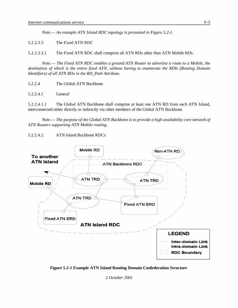
Figure 5.2-1 Example ATN Island Routing Domain Confederation Structure
Note.— An example ATN Island RDC topology is presented in Figure 5.2-1.
5.2.2.3.3 The Fixed ATN RDC
5.2.2.3.3.1 The Fixed ATN RDC shall comprise all ATN RDs other than ATN Mobile RDs.
Note.— The Fixed ATN RDC enables a ground ATN Router to advertise a route to a Mobile, thedestination of which is the entire fixed ATN, without having to enumerate the RDIs (Routing DomainIdentifiers) of all ATN RDs in the RD_Path Attribute.
5.2.2.4 The Global ATN Backbone
5.2.2.4.1 General
5.2.2.4.1.1 The Global ATN Backbone shall comprise at least one ATN RD from each ATN Island,interconnected either directly or indirectly via other members of the Global ATN Backbone.
Note.— The purpose of the Global ATN Backbone is to provide a high availability core network ofATN Routers supporting ATN Mobile routing.
5.2.2.4.2 ATN Island Backbone RDCs

V-6 Manual of Technical Provisions for the Aeronautical Telecommunication Network (ATN)
2 October 2001
5.2.2.4.2.1 Recommendation.— Within each ATN Island, those ATN RDs that are members of theGlobal ATN Backbone should form a single RDC, which is referred to as the ATN Island Backbone RDC.5.2.2.4.2.2 An ATN Island Backbone RDC, when present, shall be nested within an ATN Island RDC.
Note 1.— The purpose of the ATN Island Backbone RDC is to permit more than one ATN RD to actas the default route provider for an ATN Island. It also provides a containment boundary to limit the impactof changes in routes to Mobile RDs to only the members of the Backbone RDC and not to the rest of the ATNIsland.
Note 2.— This is only a recommended practice as in some regions, simpler, or other alternativestructures may be more appropriate for an ATN Island.
5.2.2.5 The “Home” Domain
5.2.2.5.1 Aircraft for which inter-Island communications are required shall have a “Home” domain,which is a Routing Domain in an ATN Island.
Note 1.— This “home” needs not be in either the ATN Island through which the aircraft is currentlyreachable, or in the ATN Island with which communication is required.
Note 2.— The role of the “Home” domain is to advertise a default route to all the aircraft belongingto an airline, or the General Aviation aircraft of a given country of registration. This default route isadvertised to the ATN Global Backbone in line with the routing policies specified in 5.3.7.
5.2.2.6 Administrative Domains and the ATN
5.2.2.6.1 The Administrative Domain of each administration, and aeronautical industry member thatoperates one or more ATN RDs shall comprise both their ATN RDs, and any non-ATN RDs that they operate.
Note 1.— The Routing Policies for communication between ATN and non-ATN RDs within the sameAdministrative Domain is a local matter.
Note 2.— While meeting the requirements of the SARPs, the distribution of end system andintermediate system functionality and the use of interworking processesexclusively within an AdministrativeDomain is a local matter.
5.2.2.7 Default Routes
5.2.2.7.1 The default route to all aircraft shall be a route in the context of IDRP that:
a) is available to all traffic types (see 5.2.7.1.2), and
b) has in its destination two NSAP Address prefixes. One of these is the NSAP Addressprefix that is common to all AINSC Airborne Systems and only AINSC AirborneSystems, and the other is the NSAP Address prefix that is common to all ATSCAirborne Systems and only ATSC Airborne Systems.

Internet communications service V-7
2 October 2001
5.2.2.7.2 The default route to all the aircraft belonging to an airline or the General Aviation Aircraftof a given country of registration shall be a route in the context of IDRP that:
a) is available to all traffic types (see 5.2.7.1.2), and
b) has in its destination an NSAP address prefix which is common to all AirborneSystems and only those Airborne Systems of the aircraft that belong to that airline orare registered in that country.

V-8 Manual of Technical Provisions for the Aeronautical Telecommunication Network (ATN)
2 October 2001
5.2.3 ATN End Systems
Note 1.— ATN End Systems are capable of communicating with other ATN End Systems, eitherdirectly or indirectly, to provide end-to-end communication service for Air/Ground or Ground/Groundapplications, or both.
Note 2.— An ATN End System is a realisation of the OSI End System architectural entity.
Note 3.— An ATN End System supports one or more ATN Applications and supports theircommunication over the ATN by providing either the connection mode transport service, or theconnectionless mode transport service, or both.
5.2.3.1 Physical and Data Link Layer
5.2.3.1.1 ATN End Systems shall implement the appropriate Physical and Data Link Layer functionsfor access to the ATN subnetwork(s) to which they are attached.
5.2.3.2 Network Layer
5.2.3.2.1 ATN End Systems shall implement:
a) The End System provisions of ISO/IEC 8473, as specified in 5.6, as the SubnetworkIndependent Convergence Function (SNICF).
b) a Subnetwork Access Protocol (SNAcP) suitable for each underlying subnetwork.
c) a Subnetwork Dependent Convergence Function (SNDCF) providing byte and codeindependent service to the SNICF (i.e. ISO/IEC 8473) via the appropriateSubnetwork Access Protocol, as specified in 5.7.
5.2.3.2.2 Recommendation.— ATN End Systems should implement the End System provisions ofISO/IEC 9542 to facilitate theexchange of routing information between the ES and any locally attachedIS(s).
5.2.3.3 Transport Layer
5.2.3.3.1 Depending on the requirements of the application and its supporting upper-layer protocols,ATN End Systems shall implement either one or both of the following:
a) ISO/IEC 8073 as specified in 5.5
b) ISO/IEC 8602 as specified in 5.5.
5.2.3.4 Upper Layers
Note.— The requirements for session, presentation and application layer protocols to supportend-user applications on ATN End Systems are defined in Section 4 of the ATN SARPs.
5.2.3.5 Applications

Internet communications service V-9
2 October 2001
Note.— The requirements for Air/Ground and Ground/Ground applications are contained inSections 2 and 3 of the ATN SARPs respectively.

V-10 Manual of Technical Provisions for the Aeronautical Telecommunication Network (ATN)
2 October 2001
5.2.4 ATN Routers
Note 1.— ATN Routers are capable of the relaying and routing of Network Layer protocol data unitswith other ATN Routers and with directly connected ATN End Systems.
Note 2.— An ATN Router is a realisation of the OSI Intermediate System architectural entity. ATNRouters that additionally implement ISO/IEC 10747 are also known as Boundary Intermediate Systems(BISs).
5.2.4.1 ATN Router Classes
5.2.4.1.1 The classes of ATN Router and the Routing Protocols supported, that are recognised by thisspecification, are listed below in Table 5.2-1.
Table 5.2-1 ATN Router Classes
Class Name Routing ProtocolsSupported
1. Static Router ISO/IEC 9542 (optional)
2. Level 1 Router ISO/IEC 9542 (optional)ISO/IEC 10589 Level 1only
3. Level 2 Router ISO/IEC 9542 (optional)ISO/IEC 10589 Level 1and Level 2
4. Ground/GroundRouter
ISO/IEC 9542 (optional)ISO/IEC 10589 (optional)ISO/IEC 10747
5. Air/Ground -Router(ground based)
ISO/IEC 9542ISO/IEC 10589 (optional)ISO/IEC 10747Route InitiationProcedures (see 5.3.5.2)
6. Airborne Routerwith IDRP
ISO/IEC 9542ISO/IEC 10747Route InitiationProcedures (see 5.3.5.2)
7. Airborne Routerwithout IDRP
ISO/IEC 9542Route InitiationProcedures (see 5.3.5.2)

Internet communications service V-11
2 October 2001
Note 1.— Classes 1, 2 and 3 are only for use within an ATN Routing Domain and their specificationis a local matter.
Note 2.— The intra-domain parts of Router Classes 4 and 5 are also a local matter.
Note 3.— The intra-domain parts of Router Classes 6 and 7 are concerned with the interconnectionof avionics to the airborne router and are the subject of aeronautical industry standards.
Note 4.— Router Classes 5, 6 and 7 describe routers that support at least one ATN MobileSubnetwork.
5.2.4.1.2 All ATN Routers (i.e. Router Classes 1 to 7 inclusive) shall support the ISO/IEC 8473Connectionless Network Protocol (CLNP) as specified in 5.6, including the use of the CLNP options securityparameter, and shall interpret and obey the Routing Policy Requirements expressed therein, whilst routing thepacket in accordance with any restrictions placed on the traffic types that may be carried over a given ATNSubnetwork, by forwarding CLNP NPDUs.
5.2.4.1.3 With theexceptionof AirborneRouters that implement theprocedures for theoptional non-useof IDRP (i.e. Router Class 7), all ATN Inter-Domain Routers (i.e. Router Classes 4 to 6 inclusive) shallsupport the ISO/IEC 10747 Inter-Domain Routing Protocol (IDRP) as specified in 5.8 for the exchange ofinter-domain routing information according to 5.3.6 and 5.3.7.
5.2.4.1.4 An Airborne (Router Classes 6 or 7) or Air/Ground Router (Router Class 5) shall support theMobile SNDCF specified in 5.7 for the use of CLNP over an ATN Mobile Subnetwork, and the ISO/IEC9542 ES-IS routing information exchange protocol, as specified in 5.8 for support of the route initiationprocedures specified in 5.3.5.2.
5.2.4.2 Physical and Data Link Layers
5.2.4.2.1 ATN Routers shall implement the appropriate Physical and Data Link Layer functions foraccess to the ATN subnetwork(s) to which they are attached.
5.2.4.3 Network Layer
5.2.4.3.1 An ATN Router shall implement:
a) the Intermediate System provisions of ISO/IEC 8473, as specified in 5.6, as theSubnetwork Independent Convergence Function (SNICF).
b) a Subnetwork Access Protocol (SNAcP) suitable for each underlying subnetwork.
c) a Subnetwork Dependent Convergence Function (SNDCF) providing byte and codeindependent service to the SNICF (i.e. ISO/IEC 8473) via the selected SubnetworkAccess Protocol, as specified in 5.7.

V-12 Manual of Technical Provisions for the Aeronautical Telecommunication Network (ATN)
2 October 2001
d) The routing protocols specified in Table 5.2-1 for the Router*s Router Class, asspecified in 5.8.
e) The Route Initiation procedures appropriate to the Router Class, as specified in 5.3.
f) Where an ATN Router is directly connected to one or more Mobile Subnetworks, itshall implement a sub-set of the ISO/IEC 9542 for operation over those subnetworksto facilitate the exchange of addressing information (BIS Network Entity Title)between the Router and its peer as specified in 5.3 (see 5.3.5.2) and in 5.8.
5.2.4.3.2 ATN Routers of class 5 (Air/Ground Routers)andofclass 7 (AirborneRouters without IDRP)shall also implement the mechanisms necessary to support the “optionalnon-use of ISO/IEC10747” asspecified in 5.3.
5.2.4.3.3 Recommendation.— All ATN Airborne Routers should support the use of ISO/IEC 10747(i.e. Class 6 is the preferred Airborne Router Class).
Note.— Some States may elect to support the optional non-use of airborne IDRP procedures in theirAir/Ground Routers; however, Regional Implementation Planning Groups must acknowledge the requirementfor aircraft using IDRP within the Region to communicate with an Air/Ground Router, independent of howthat is accomplished.

Internet communications service V-13
2 October 2001
5.2.5 ATN Subnetworks
Note.— An ATN Subnetwork is any fixed or Mobile data communications network that fulfils thefollowing requirements.
5.2.5.1 Requirements for All ATN Subnetworks
5.2.5.1.1 Paragraph has been deleted.
5.2.5.1.2 Byte and Code Independence
5.2.5.1.2.1 Data shall be transferred through ATN Subnetworks in a byte and code independent manner.
Note.— If necessary, this byte and code independence may be ensured through the services of theSNDCF.
5.2.5.1.3 Subnetwork QoS
5.2.5.1.3.1 A Subnetwork service provider shall provide an indication of the Subnetwork Quality ofService (QoS) available, in order to support the internetwork routing decision process.
5.2.5.1.4 Subnetwork Addressing
5.2.5.1.4.1 An ATN subnetwork shall provide a mechanism for uniquely and unambiguously identifyingeach ATN router attached to that subnetwork.
5.2.5.1.5 Internal Subnetwork Routing
5.2.5.1.5.1 Routing between specified source and destination Subnetwork Point of Attachment (SNPA)addresses on an ATN subnetwork shall be carried out by mechanisms internal to the subnetwork.
5.2.5.2 Requirements for ATN Mobile Subnetworks
5.2.5.2.1 Paragraph has been deleted.
5.2.5.2.2 Invocation of Subnetwork Priority
5.2.5.2.2.1 When priority is implemented within that subnetwork, an ATN Mobile Subnetwork shallprovide a SNAcP mechanism for invocation of subnetwork priority.
5.2.5.2.3 Invocation of Subnetwork Quality of Service for Mobile Subnetworks
5.2.5.2.3.1 Recommendation.— ATN Mobile Subnetworks should provide a mechanism for invocationof subnetwork QoS.

V-14 Manual of Technical Provisions for the Aeronautical Telecommunication Network (ATN)
2 October 2001
Note 1.— Subnetwork QoS parameters include transit delay, protection against unauthorizedaccess, cost determination and residual error probability.
Note 2.— ATN Mobile Subnetworks may allocate subnetwork resources on a per user or persubnetwork connection basis in order to make available a different QoS.
5.2.5.2.4 Connection-Mode Subnetwork Service
5.2.5.2.4.1 An ATN Mobile Subnetwork shall provide a connection-mode service between SNPAs, witha well-defined start and end to a connection, and with reliable, sequenced SNSDU transfer over that connection.
5.2.5.2.4.2 When QoS is available on a per subnetwork connection basis, the SNAcP shall providemechanisms for selecting a specific QoS when the subnetwork connection is established.
Note 1.— A Mobile Subnetwork implementing ISO/IEC 8208 to provide a connection-mode servicebetween SNPAs meets this requirement; however, where appropriate, an alternative protocol providing thesame service may be used.
Note 2.— This requirement does not imply the need for a single Mobile SNAcP.
5.2.5.2.5 Connectivity Status Changes
Note.— ATN Mobile Subnetworks are assumed to provide a mechanism for detection of change inmedia connectivity. The mechanism is both subnetwork and implementation dependent and is outside thescope of this specification.
5.2.5.2.5.1 An ATN Mobile Subnetwork shall provide subnetwork connectivity information to connectedsubnetwork service users (i.e. connected ATN routers), in order to initiate operation of the internetwork routingprotocols as specified in 5.3.
Note 1.— Themechanism by which the subnetwork connectivity information is conveyed to connectedATN routers is both subnetwork and implementation dependent and is outside the scope of this specification.
Note 2.— It is desirable for the Intermediate System - Systems Management Entity (IS-SME) to benotified as soon as possible by the SN-SME when communication is possible with a newly attached BIS andfor an immediate decision to be made as regards bringing up the link.
5.2.5.2.5.1.1 ATN Mobile Subnetworks shall issue a Join Event (see 5.3.5.2) to the attached IS-SME toindicate the availability of a physical communication path between a pair of SNPAs.
5.2.5.2.5.1.2 ATN Mobile Subnetworks shall issue a Leave Event (see 5.3.5.2.13) to the attached IS-SMEto indicate that a previously available physical communication path between a pair of SNPAs is no longeravailable.

Internet communications service V-15
2 October 2001
5.2.5.2.5.1.2.1 ATN Mobile Subnetworks supporting theATN Operational Communications traffic type andthe ATSC traffic category (see 5.2.7.1.2) shall have a maximum delay, at 95% probability, for issueing aLeave Event consistent with the requirements in 5.2.7.1.3 for the ATSC Class supported by that subnetwork.
5.2.5.2.6 Segmentation/Reassembly Mechanism
5.2.5.2.6.1 Recommendation.— An ATN Mobile Subnetwork should provide a mechanism that allowsthe conveyance of large SNSDUs greater than the subnetwork's internal packet size between SNPAs.
Note.— It is the responsibility of the subnetwork to ensure that this data is efficiently segmentedand/or concatenated for efficient transfer over the physical medium. If this capability is not present withinan ATN Mobile Subnetwork, ISO/IEC 8473 can support segmentation of NPDUs for transit over subnetworkswith small maximum SNSDU sizes.

V-16 Manual of Technical Provisions for the Aeronautical Telecommunication Network (ATN)
2 October 2001
5.2.6 Quality of Service Concept
Note 1.— In the ATN, the Quality of Service provided to applications is maintained using capacityplanning techniques that are outside of the scope of this specification. Network Administrators areresponsible for designing and implementing a network that will meet the QoS requirements of the ATNapplications that use it.
Note 2.— Network Administrators may take advantage of the QoS requirements signalled by theATSC Class (see 5.2.7.1.3), in order to ensure that only those parts of the ATN that support the QoSrequirements of ATSC applications, need be designed to meet those requirements.
Note 3.— In order to support the QoS requirements of ATSC applications, this specification definesthe maximum one-way ATN End-to-End Transit Delay (see Table 1-1) as well as the maximum one-way ATNMobile Subnetwork Transit Delay and the Maximum Delay in Issuing a Leave Event for ATN MobileSubnetworks supporting ATN Operational Communications - ATSC traffic (see Table 5.2-2).

Internet communications service V-17
2 October 2001
5.2.7 ATN Security Concept
Note 1.— ATN Security Functions are concerned with:
a) Protecting ATN Data Link applications from internal and external threats;
b) Ensuring that application Quality of Service and Routing Policy Requirements aremaintained, including service availability;
c) Ensuring that Air/Ground subnetworks areused in accordance with ITU resolutionson frequency utilisation; and
d) Protecting routing information exchanges among ATN BISs.
Note 2.— There are no security mechanisms provided in the ATN Internet for protecting ATN DataLink applications. ATN Data Link applications are protected by upper layer security functions in ATN ESswhich implement ATN security services as defined in 4.
Note 3.— The ATN Internet supports item (d) above through the use of ISO/IEC10747 type 2authentication in ATN ISs which implement ATN security services.
Note 4.— The ATN Internet does provide mechanisms to support items (b) and (c) above. Thesemechanisms are defined to take place in a common domain of trust, and use a Security Label in the headerof each CLNP PDU to convey information identifying the “traffic type” of the data and the application*srouting policy and/or strong QoS Requirements. No mechanisms are provided to protect the integrity of thislabel or its binding to the application data.
Note 5.— In order to permit the later extension of the ATN to handle classified data, the SecurityLabel in the CLNP PDU header can additionally be used to convey Security Classification information.
Note 6.— The Routing Information necessary to support this Security Label is maintained throughinformation conveyed in the ISO/IEC 10747 Security Path Attribute about each route. ATN Routers of classes4 and above reference this routing information during the NPDU forwarding process in order to meet theapplication*s requirements expressed through the NPDU*s Security Label and to enforce any applicable ITUresolutions on frequency utilisation.
5.2.7.1 The ATN Security Label
5.2.7.1.1 General
5.2.7.1.1.1 The ATN Security Label shall be encoded according to 5.6.2.2.2.
5.2.7.1.1.2 An ATN Security Label shall be provided as part of the header of every CLNP NPDU, exceptfor those that convey General Communications applications data.

V-18 Manual of Technical Provisions for the Aeronautical Telecommunication Network (ATN)
2 October 2001
Note.— The above implies that any CLNP NPDU that does not contain an ATN Security Labelcontains General Communications data.
5.2.7.1.2 Traffic Types
5.2.7.1.2.1 A CLNP Data NPDU*s Security Label shall identify the “Traffic Type” of its user data, aseither:
a) ATN Operational Communications
b) ATN Administrative Communications
c) ATN Systems Management Communications.
Note.— ATN Operational Communications traffic type is broken down into two categories: ATSCand AOC (see Table 5.6-1).
5.2.7.1.2.2 For theATN Operational Communications traffic typeand theATSC traffic category, routingpolicy requirements shall be expressed through further information encoded into the Security Label, as either:
a) A preferred ATSC Class, or
b) no routing policy preference.
5.2.7.1.2.3 For the ATN Operational Communications traffic type and the AOC traffic category, routingpolicy requirements shall be expressed through further information encoded into the Security Label, as eitherno routing policy preference, or an ordered list of appropriate Air/Ground subnetworks to be used.
Note.— The possible ordering of Air/Ground subnetworks are specified in Table 5.6-1.
5.2.7.1.3 ATSC Class
5.2.7.1.3.1 ATN Mobile Subnetworks supporting theATN Operational Communications traffic type andthe ATSC traffic category shall satisfy the maximum subnetwork transit delay requirements specified in Table5.2-2 for the advertised ATSC Class.
5.2.7.1.3.2 ATN Mobile Subnetworks supporting theATN Operational Communications traffic type andthe ATSC traffic category shall satisfy the maximum delay requirements in issueing a Leave Event as indicatedin either the third or/and the fourth column of Table 5.2-2 for the advertised ATSC Class.
Table 5.2-2 Subnetwork Transit Delay and Leave Event Issuance Maximum Delay

Internet communications service V-19
2 October 2001
ATSC Class Maximum One-wayATN Mobile Subnet-work Transit Delay at
95% Probability(in seconds)
Maximum Delay, at95% Probability, in
Issuing a Leave Eventin the Absence of NPDU
Traffic(in seconds)
Maximum Delay, at95% Probability, in
Issuing a Leave Eventin the Presence of
NPDU Traffic(in seconds)
A reserved reserved reserved
B 3.0 27 18
C 5.7 44 29
D 10 81 54
E 14.5 108 72
F 23.5 162 108
G 46.5 300 240
H 96.5 > 300 > 240
Note 1.— The ATN End-to-End Transit Delay semantics of the ATSC Class are defined in Table 1-1.
Note 2.— The maximum one-way ATN mobile subnetwork transit delay is for data packets associatedwith ATSC high priority flight safety messages, as defined in Table 1-3, when delivered by the mobilesubnetwork operating at the nominal maximum subnetwork loading (e.g., serving the maximum number ofusers the subnet is designed to handle on the available radio frequency channel(s)).
Note 3.— The delay in issuing a Leave Event (see 5.2.5.2.5.1.2.1) is defined as the time from whena previously available physical communication path is no longer available until the time the Leave Event isactually issued to the attached IS-SME.
Note 4.— An example for the loss of a physical communication path would be an aircraft movingout of the coverage of the VDL Mode 2 ground stations belonging to a given VDL Mode 2 ground system.
Note 5.— In the case of ongoing air/ground data exchange, the arrival of an NPDU from an attachedATN Router may be used by the subnetwork as the event to detect loss of a previously availablecommunication path. In this case (i.e. fourth column of Table 5.2-2) detection of the loss of subnetworkconnectivity and issuance of a Leave Event is expected to be more expeditious than in the absence of datatraffic (i.e. third column of Table 5.2-2).
Note 6.— The semantics of the ATSC Class for other QoS metrics and availability are outside ofthe scope of this specification.

V-20 Manual of Technical Provisions for the Aeronautical Telecommunication Network (ATN)
2 October 2001
5.2.7.1.4 Security Classification
Note.— The Security Classification may be used to convey the confidentiality level of applicationdata.
5.2.7.2 Applications Use of ATN Security Labels
5.2.7.2.1 ATN Data Link applications shall specify an ATN Security Label for each message categorythat they support. This ATN Security Label shall identify:
a) the Traffic Type appropriate for the message; and,
b) for ATN Operational Communications applications, the application*s requirementsfor the routing of the message, if any, expressed as specified in 5.2.7.1.2.
5.2.7.2.2 When sent using theconnection-modetransport service, a messageshall only be conveyed overa transport connection which is associated with the same ATN Security Label as that specified for themessage*s message category.
5.2.7.2.3 When sent using theconnectionless-modetransport service, theTSDU conveying that messageshall be associated with the ATN Security Label of the specified message category.
5.2.7.3 Transport Layer Security
5.2.7.3.1 In the Connection Mode
5.2.7.3.1.1 Except when a transport connection is used to convey general communications data, eachtransport connection shall be associated with a single ATN Security Label.
5.2.7.3.1.2 The value of this label shall be determined when the connection is initiated.
Note.— It is not possible to change an ATN Security Label during the lifetime of a transportconnection.
5.2.7.3.1.3 Every NSDU passed to the Network Layer that contains a TPDU from a transport connectionassociated with an ATN Security Label shall be associated with the same ATN Security Label.
Note.— The Network Layer functions may then encode this ATN Security Label in the NPDU header.
5.2.7.3.1.4 TPDUs from transport connections associated with different ATN Security Labels shall notbe concatenated into the same NSDU.
5.2.7.3.1.5 When an incoming CR TPDU is received, the ATN Security Label, if any, encoded into theheader of the NPDU that conveyed it, shall define the ATN Security Label that is associated with the transportconnection.

Internet communications service V-21
2 October 2001
Note 1.— The mechanism by which the connection initiator provides the appropriate ATN SecurityLabel is a local matter. For example, it may be identified by an extension to the transport service interface,be implicit in the choice of a given TSAP, or be identified using a Systems Management function.
Note 2.— Some applications may reject incoming transport connections for which the ATN SecurityLabel is inappropriate. Again, the mechanism by which the Transport provider passes to its user the ATNSecurity Label associated with an incoming transport connection is a local matter.
5.2.7.3.2 In the Connectionless Mode
5.2.7.3.2.1 In the connectionless mode, unless used to convey General Communications data, eachincoming or outgoing TSDU shall be associated with an ATN Security Label.
5.2.7.3.2.2 For outgoing TSDUs, this ATN Security Label shall beencoded into theheader of theresultingNPDU(s).
5.2.7.3.2.3 For incoming TSDUs, the associated ATN Security Label shall be the ATN Security Labelthat was encoded into the header of the incoming NPDU(s) that contained the TSDU.
Note.— The mechanism by which ATN Security Labels are associated with TSDUs is a local matter.
5.2.7.4 Network Layer Security
5.2.7.4.1 Service Provider to the Transport Layer
5.2.7.4.1.1 The Network Service shall provide a mechanism that permits an ATN Security Label to beassociated with an NSDU:
a) When passed from the Transport Layer to the Network Layer in an NS-UNITDATA.request. This ATN Security Label shall be encoded into the header ofthe corresponding CLNP NPDU(s) according to 5.6.2.2.2.
b) When passed from the Network Layer to the Transport Layer in anNS-UNITDATA.indication. This ATN Security Label shall be that received in theheader of the associated CLNP NPDU(s).
5.2.7.4.2 Routing Control
5.2.7.4.2.1 When present in an NPDU header, the network layer routing functions shall ensure that:
a) The Routing Policy requirements, if any, encoded into the ATN Security Label areobeyed, and
b) The NPDU is only routed over paths through the internetwork which both permit andare suitable for data of the traffic type identified by the ATN Security Label.
Note 1.— 5.3.2.2 specifies the forwarding procedures that ensure the above.
V-22 Manual of Technical Provisions for the Aeronautical Telecommunication Network (ATN)
2 October 2001
Note 2.— The Security Information conveyed in ISO/IEC 10747 (IDRP) routes is used to providethe forwarding process with the information needed to support the above.
5.2.7.4.3 Protection of the Routing Information Base
5.2.7.4.3.1 IDRP type 1 authentication, as specified in ISO/IEC 10747, shall be supported by all ATNrouters implementing the ISO/IEC 10747 protocol (i.e. Router Classes 4 to 6 inclusive) as a mechanism forensuring the integrity of routing information exchange by IDRP.
5.2.7.4.3.2 ATN Routers supporting ATN security services shall support IDRP type 2 authentication inaddition.
Note 1.— Support of type 2 authentication enables the routing information base to be protected fromattackers that try to modify routing information while in transit, or which attempt to masquerade as genuineATN Routers.
Note 2.— The ATN security services comprise a set of information security provisions which allowthe receiving ES or IS to unambiguously identify the source of the received information and to verify theintegrity of this information. Use of the IDRP type 2 authentication is a key feature of the ATN securityservices provided in the ATN Internet.
Note 3.— The use of the ATN security services in the ATN Internet is a conceptually differentmechanism to those functions provided by the use of the ATN Security Label. The latter mechanism ensuresthat application QoS, routing policy requirements and restrictions of Mobile Subnetworks are enforcedwithin a common domain of trust.
5.2.7.5 Subnetwork Provisions
Note.— There are no requirements for security mechanisms in ATN Subnetworks. However,Administrations and other Organisations implementing ATN subnetworks are encouraged to ensure thegeneral security and availability of ATN subnetworks through the use of physical security mechanisms.

Internet communications service V-23
2 October 2001
5.2.8 ATN Use of Priority
Note 1.— The purpose of priority is to signal the relative importance and/or precedence of data,such that when a decision has to be made as to which data to action first, or when contention for access toshared resources has to be resolved, the decision or outcome can be determined unambiguously and in linewith user requirements both within and between applications.
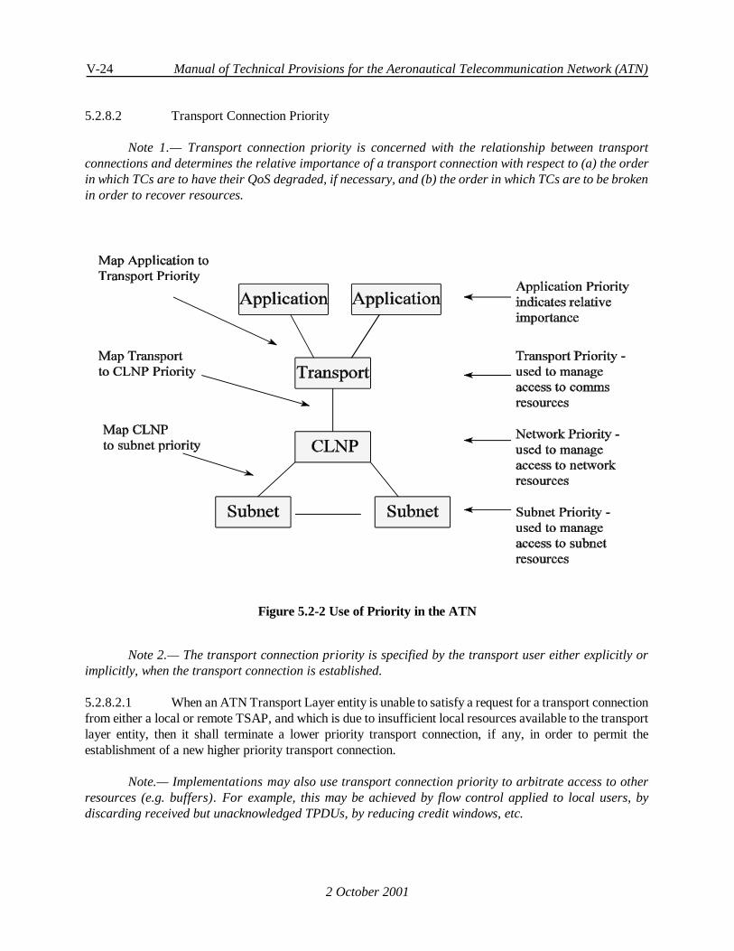
Note 2.— In the ATN, priority is signalled separately by the application in the transport layer andnetwork layer, and in ATN subnetworks. In each case, the semantics and use of priority may differ.Figure 5.2-2 illustrates where priority is applied in the ATN, and where it is necessary to map the semanticsand syntax of ATN priorities.
Note 3.— In the ATN Internet, priority has the essential role of ensuring that high priority safetyrelated data is not delayed by low priority non-safety data, and in particular when the network is overloadedwith low priority data.
5.2.8.1 Application Priority
Note.— Priority in ATN Application Protocols is used to distinguish the relative importance andurgency of application messages within the context of that application alone.
5.2.8.1.1 For the purpose of
a) distinguishing the relative importance and urgency of messages exchanged bydifferent ATN Applications, and
b) distinguishing the relative importance and urgency of messages of the sameapplication during their transit through the ATN,
application messages shall be grouped into one or more categories listed in Table 1-2 .
Note.— An ATN Application may include messages from more than one category.
5.2.8.1.2 When a message is sent between ATN Application Entities, the message shall be sent usingeither:
a) a transport connection established using the Transport Connection Priority listed inTable 1-2 for the message*s message category, or
b) the connectionless transport service, signalling the Connectionless Transport ServicePriority listed in Table 1-2 for the message*s message category.
Note.— The priority of an individual transport connection cannot be changed during the lifetime ofthe connection. Therefore, if an application exchanges messages belonging to more than one messagecategory using the connection mode transport service, then a separate transport connection needs to beestablished for each message category.
V-24 Manual of Technical Provisions for the Aeronautical Telecommunication Network (ATN)
2 October 2001
Figure 5.2-2 Use of Priority in the ATN
5.2.8.2 Transport Connection Priority
Note 1.— Transport connection priority is concerned with the relationship between transportconnections and determines the relative importance of a transport connection with respect to (a) the orderin which TCs are to have their QoS degraded, if necessary, and (b) the order in which TCs are to be brokenin order to recover resources.
Note 2.— The transport connection priority is specified by the transport user either explicitly orimplicitly, when the transport connection is established.
5.2.8.2.1 When an ATN Transport Layer entity is unable to satisfy a request for a transport connectionfrom either a local or remote TSAP, and which is due to insufficient local resources available to the transportlayer entity, then it shall terminate a lower priority transport connection, if any, in order to permit theestablishment of a new higher priority transport connection.
Note.— Implementations may also use transport connection priority to arbitrate access to otherresources (e.g. buffers). For example, this may be achieved by flow control applied to local users, bydiscarding received but unacknowledged TPDUs, by reducing credit windows, etc.

Internet communications service V-25
2 October 2001
5.2.8.2.2 All TPDUs sent by an ATN Transport Layer Entity shall be transferred by the ATN InternetLayer, using the Network Protocol Priority that corresponds to the transport connection*s priority accordingto Table 1-2.
5.2.8.3 Connectionless Transport Service Priority
Note.— There are no procedures required of the ATN Connectionless Transport Entity in respectof priority, except for mapping the TSDU priority supplied by the service user (i.e. an ATN Application), tothe corresponding Network Layer Priority, and vice versa.
5.2.8.3.1 All UD TPDUs sent by an ATN Transport Layer Entity shall be transferred by the ATNInternet Layer using the Network Protocol Priority that corresponds to the TSDU priority provided by theservice user according to Table 1-2.
5.2.8.4 ATN Internet Priority
Note.— In the ATN Internet Layer, an NPDU of a higher priority is given preferred access toresources. During periods of higher network utilisation, higher priority NPDUs may therefore be expectedto be more likely to reach their destination (i.e. are less likely to be discarded by a congested router) and tohave a lower transit delay (i.e. be more likely to be selected for transmission from an outgoing queue) thanare lower priority packets.
5.2.8.4.1 ATN Internet Entities shall maintain their queues of outgoing NPDUs in strict priority order,such that a higher priority NPDU in an outgoing queue will always be selected for transmission in preferenceto a lower priority NPDU.
Note.— Priority zero is the lowest priority.
5.2.8.4.2 During periods of congestion, or when any other need arises to discard NPDUs currently heldby an ATN Internet Entity, lower priority NPDUs shall always be discarded before higher priority NPDUs.
Note.— In addition to NPDUs containing user (i.e. transport layer) data, the Internet Layer alsoforwards routing information contained in CLNP Data PDUs (e.g. IDRP) and as distinct NPDUs (e.g. ES-IS). These must all be handled at the highest priority if changes to network topology are to be quicklyactioned and the optimal service provided to users.
5.2.8.4.3 BISPDUs exchanged by IDRP shall beconsidered as Network/Systems Management categorymessages, and shall be sent using CLNP priority 14.
5.2.8.4.4 ES-IS (ISO/IEC 9542) PDUs shall be implicitly assumed to have priority 14 and shall beforwarded as if they were CLNP PDUs of priority 14.
Note.— The priority encoded in an ISH PDU conveys the priority of the sending system, and not thepriority of the PDU.

V-26 Manual of Technical Provisions for the Aeronautical Telecommunication Network (ATN)
2 October 2001
5.2.8.5 ATN Subnetwork Priority
5.2.8.5.1 Connection-Mode Subnetworks
Note 1.— In a connection-mode ATN subnetwork, priority is used to distinguish the relativeimportance of different data streams (i.e. the data on a subnetwork connection), with respect to gainingaccess to communications resources and to maintaining the requested Quality of Service.
Note 2.— On some subnetworks (e.g. public data networks), not all data streams will be carryingATN messages. Therefore, subnetwork priority is also used to distinguish ATN and non-ATN data streams.
Note 3.— So as not to incur the overhead and cost of maintaining too many simultaneoussubnetwork connections, NPDUs of a range of Network Layer priorities may be sent over the samesubnetwork connection.
5.2.8.5.1.1 When an ATN connection mode subnetwork does not support prioritisation of subnetworkconnections, then the ATN Internet Entity shall not attempt to specify a subnetwork connection priority, andNPDUs of any priority may be sent over the same subnetwork connection.
5.2.8.5.1.2 When an ATN connection mode subnetwork does support prioritisation of subnetworkconnections, then unless the relationship between ATN Internet Priority and subnetwork priority is explicitlyspecified by the subnetwork specification, the following shall apply:
a) Subnetwork connections shall be established as either “High” or “Low” priorityconnections.
b) For the “Low” priority connection type, the priority to gain a connection, keep aconnection and for data on the connection shall be the defaults for routine use of thesubnetwork.
c) “High” priority connections shall be used to convey NPDUs of priority ten and above.“Low” priority connections shall be used to convey all other NPDUs.
Note.— The above does not apply to the AMSS Subnetwork, which has specified its own prioritymapping scheme.
5.2.8.5.1.3 When a subnetwork connection is established between two ATN Internet Entities and no othersubnetwork connection between thesetwo entities exists over any subnetwork, then that subnetwork connectionshall always be established at a priority suitable for conveying NPDUs of priority 14 (i.e. Network/SystemsManagement).
Note.— This is to ensure that routing information can be exchanged at the appropriate priority.
5.2.8.5.2 Connectionless-Mode Subnetworks
Note 1.— The purpose of priority on a connectionless-mode subnetwork is to provide higher priorityNPDUs with preferred access to subnetwork resources.
Note 2.— The relationship between NPDU priority and subnetwork priority is subnetwork specific.

Internet communications service V-27
2 October 2001
5.2.8.5.2.1 When an NPDU is sent over a connectionless-mode ATN Subnetwork which supports dataprioritisation, then the subnetwork priority assigned to the transmitted packet shall be that specified by thesubnetwork provider as corresponding to the NPDU priority.

V-28 Manual of Technical Provisions for the Aeronautical Telecommunication Network (ATN)
2 October 2001
5.3 ATN ROUTING
5.3.1 Introduction
5.3.1.1 Scope
Note.— This chapter provides requirements and recommendations pertaining to the deployment ofATN components within the ATN Internet; use of routing information distributed according to ISO/IEC10747 in order to support policy based and Mobile routing in the ATN; and the Route Initiation proceduresfor initiating the exchange of routing information using the ISO/IEC 10747 protocol. In the case ofAir/Ground data links, route initiation also includes the use of the ISO/IEC 9542 protocol. This chapter isnot concerned with compliancy with the ISO/IEC 10747 and ISO/IEC 9542 protocols. This is the subject of5.8.
5.3.1.2 Applicability of Requirements
Note 1.— The classes of ATN Router referred to below are defined in 5.2.4.1.
Note 2.— The ATN RDs referred to below are defined in 5.2.2.2.
5.3.1.2.1 ATN Ground/Ground Routers shall comply with the provisions of 5.3.4 and 5.3.6.
5.3.1.2.2 When used as an ATN Router in an ATN RD that is a member of an ATN Island BackboneRDC, an ATN Ground/Ground Router shall also comply with the provisions of 5.3.7.1.
5.3.1.2.3 When used in any other ATN Transit Routing Domain, an ATN Ground/Ground Router shallalso comply with the provisions of 5.3.7.3.
5.3.1.2.4 Otherwise, an ATN Ground/Ground Router shall comply with the provisions of 5.3.7.4.
5.3.1.2.5 ATN Air/Ground Routers shall comply with the provisions of 5.3.4 for Ground/Groundinterconnection, 5.3.5 for Air/Ground interconnection and 5.3.6.
5.3.1.2.6 When used as an ATN Router in an ATN RD that is a member of an ATN Island BackboneRDC, an ATN Air/Ground Router shall also comply with the provisions of 5.3.7.1.
5.3.1.2.7 When used in any other ATN Transit Routing Domain, an ATN Air/Ground Router shall alsocomply with the provisions of 5.3.7.3.
5.3.1.2.8 ATN Airborne Routers shall comply with the provisions of 5.3.5, 5.3.6, and 5.3.7.2.
5.3.1.2.9 When an RD is declared to be an ATN RD, then it shall comply with the provisions of 5.2.2.2.
5.3.1.2.10 When an RD is declared to be a Mobile RD, then it shall comply with the provisions of5.2.2.2.3.
5.3.1.2.11 When an RDC is declared to be an ATN Island RDC, then its member RDs shall comply withthe provisions of 5.2.2.3.2.

Internet communications service V-29
2 October 2001
5.3.1.2.12 When an RDC is declared to be an ATN Island Backbone RDC, then its member RDs shallcomply with the provisions of 5.2.2.4.2.

V-30 Manual of Technical Provisions for the Aeronautical Telecommunication Network (ATN)
2 October 2001
5.3.2 Service Provided by an ATN Router
5.3.2.1 General
5.3.2.1.1 A route shall only be advertised by an ATN Router to an adjacent ATN RD when it can beensured that data sent over that route by the RD to which the route is advertised is acceptable to every RD andRDC in the route's path, and will be relayed by them to the route's destination.
Note.— The acceptability of a route may be determined using a priori knowledge derived frominterconnection agreements with other RDs.
5.3.2.2 Forwarding CLNP NPDUs
5.3.2.2.1 General
5.3.2.2.1.1 The forwarding processes for a CLNP NDPU shall operate by selecting the FIB identified bythe combination of the QoS Maintenance and Security Parameters found in the CLNP Header, and selectingfrom that FIB, the entry, if any, identified by the longest matching NSAP Address Prefix.
5.3.2.2.1.2 The next hop information found in this FIB entry shall then be used to forward the NPDU.
Note.— Forwarding decisions that take into account the CLNP QoS Maintenance Parameter are alocal matter and an ATN Router may hence ignore this parameter.
5.3.2.2.2 Forwarding a CLNP NPDU when no Security Parameter is present in the PDU Header
Note.— This case applies for General Communications data (see 5.2.7.1).
5.3.2.2.2.1 When a CLNP NPDU is received by an ATN Router and that NPDU does not contain aSecurity Parameter in the PDU Header then that NPDU shall be forwarded over the selected route to theNPDU’s destination with the longest matching NSAP Address Prefix and which, either:
1) contains a security path attribute comprising the ATN Security RegistrationIdentifier and security information that does not contain an ATSC ClassSecurity Tag indicating support for only ATSC traffic, and comprises:
a) either an Air/Ground Subnetwork Security Tag that has “GeneralCommunications” in its set of permissible Traffic Types, or
b) no Air/Ground Subnetwork Security Tag,
or
2) does not contain any security path attribute.
5.3.2.2.2.2 If no such route can be found then the NPDU shall be discarded.

Internet communications service V-31
2 October 2001
5.3.2.2.3 Forwarding a CLNP NPDU when a Security Parameter is present in the PDU Header
5.3.2.2.3.1 General
5.3.2.2.3.1.1 When a CLNP NPDU is received by an ATN Router and that NPDU contains a SecurityParameter in the Globally Unique Format, and encodes security related information according to 5.6.2.2 underthe ATN Security Registration Identifier, then the NPDU shall be forwarded according to the proceduresspecified below.
Note 1.— The CLNP NPDU Header Security Parameter is used to indicate the Traffic Type of theapplication data contained in the NPDU, and the application*s routing policy requirements.
Note 2.— The procedures for handling an NPDU with any other format of Security Parameter, orwith any other Security Registration Identifier are outside the scope of this specification.
5.3.2.2.3.2 ATN Operational Communications Traffic Type - ATSC Traffic Category
Note.— In this case, either no Traffic Type policy preference may be specified, or an ATSC Classmay be specified.
5.3.2.2.3.2.1 No Traffic Type Policy Preference
Note.— This case corresponds to a Traffic Type and Associated Routing Policy Security Tag valueof 000 00001.
5.3.2.2.3.2.1.1 If the NPDU contains a CLNP NPDU Header Security Parameter in the globally uniqueformat, and encodes:
a) security related information according to 5.6.2.2 under theATN Security RegistrationIdentifier, and
b) a traffic type of ATN Operational Communications and a traffic category of AirTraffic Service Communications, and
c) no Traffic Type Policy Preference,
then the NPDU shall be forwarded over the selected route to the NPDU*s destination with the longest matchingNSAP Address Prefix, and which contains a security path attribute comprising the ATN Security RegistrationIdentifier and security information that comprises:
i. An Air/Ground Subnetwork Security Tag that has “ATN Operational Communications - AirTraffic Services Communications” in its set of permissible Traffic Types, or
ii. no Air/Ground Subnetwork Security Tag,
V-32 Manual of Technical Provisions for the Aeronautical Telecommunication Network (ATN)
2 October 2001
and an ATSC Class Security Tag indicating support of the lowest class out of all such routes available.
Note 1.— The requirement in 5.3.2.2.1.1 always takes precedence over selection based on ATSCClass i.e. a route with a longer matching NSAP Address Prefix with a higher ATSC Class is always preferredover a route with a lower ATSC Class but with a shorter NSAP Address Prefix. This is essential for theavoidance of routing loops.
Note 2.— ATSC Class “H” is the lowest and Class “A” is the highest.
5.3.2.2.3.2.1.2 If no such route can be found, then the NPDU shall be discarded.
5.3.2.2.3.2.2 ATSC Class Specified
Note.— This case corresponds to Traffic Type and Associated Routing Policy Security Tag values000 10000 to 000 10111 inclusive.
5.3.2.2.3.2.2.1 If the NPDU contains a CLNP Header Security Parameter in the globally unique format, andencodes:
a) security related information according to 5.6.2.2 under theATN Security RegistrationIdentifier, and
b) a traffic type of ATN Operational Communications and Air Traffic ServiceCommunications traffic category, and
c) a requirement to route the NPDU over a route of a specified ATSC Class,
then the NPDU shall be forwarded over the selected route to the NPDU*s destination with the longest matchingNSAP Address Prefix, and which contains a security path attribute comprising the ATN Security RegistrationIdentifier and security information that comprises:
i. An Air/Ground Subnetwork Security Tag that has “ATN OperationalCommunications - Air Traffic Services Communications” in its set of permissibleTraffic Types, or
ii. no Air/Ground Subnetwork Security Tag
and an ATSC Class Security Tag indicating:
I. support of the required class, or a higher class, or
II. if no such route is available then, the route with the highest ATSC Class available ischosen.
Note 1.— The requirement in 5.3.2.2.1.1 always takes precedence over selection based on ATSCClass i.e. a route with a longer matching NSAP Address Prefix with a higher ATSC Class is always preferred
Internet communications service V-33
2 October 2001
over a route with a lower ATSC Class but with a shorter NSAP Address Prefix. This is essential for theavoidance of routing loops.
Note 2.— ATSC Class “H” is the lowest and Class “A” is the highest.
5.3.2.2.3.2.2.2 If no such route can be found then the NPDU shall be discarded.
5.3.2.2.3.2.2.3 If multiple routes are available which meet or exceed the required ATSC Class, then the routewith the lowest relative cost, i.e. actual monetary cost, shall be selected.
Note.— The actual monetary cost is determined through means outside the scope of thisspecification.
5.3.2.2.3.2.2.4 If the monetary cost is the same or unknown, then the hop count shall be used as the relativecost metric.
5.3.2.2.3.3 ATN Operational Communications Traffic Type - AOC Traffic Category
Note.— In this case, either no routing policy may be specified, or an Air/Ground Subnetwork typemay be specified, or an Air/Ground subnetwork order of preference may be specified.
5.3.2.2.3.3.1 No Traffic Type Policy Preference
Note.— This case corresponds to a Traffic Type and Associated Routing Policy Security Tag valueof 001 00001.
5.3.2.2.3.3.1.1 If the NPDU contains a CLNP Header Security Parameter in the globally unique format, andencodes:
a) security related information according to 5.6.2.2 under theATN Security RegistrationIdentifier, and
b) a traffic type of ATN Operational Communications and Aeronautical OperationalControl traffic category, and
c) no Traffic Type Policy Preference,
then the NPDU shall be forwarded over the selected route to the NPDU*s destination with the longest matchingNSAP Address Prefix, and which contains a security path attribute comprising the ATN Security RegistrationIdentifier and security information that comprises:
i. an Air/Ground Subnetwork Security Tag that has “ATN OperationalCommunications - Aeronautical Operational Control” in its set of permissible TrafficTypes, or
ii. no Air/Ground Subnetwork Security Tag;

V-34 Manual of Technical Provisions for the Aeronautical Telecommunication Network (ATN)
2 October 2001
and which does not contain an ATSC Class Security Tag indicating support for only ATSC traffic.
5.3.2.2.3.3.1.2 If no such route can be found, then the NPDU shall be discarded.
5.3.2.2.3.3.2 Air/Ground Subnetwork Type Specified
Note 1.— This case corresponds to Traffic Type and Associated Routing Policy Security Tag values001 00010 through to 001 00110 inclusive.
Note 2.— The Air/Ground Subnetworks that may be specified are: Gatelink, VDL, AMSS, HF andMode S.
5.3.2.2.3.3.2.1 If the NPDU contains a CLNP Header Security Parameter in the globally unique format, andencodes:
a) security related information according to 5.6.2.2 under theATN Security RegistrationIdentifier, and
b) a traffic type of ATN Operational Communications and Aeronautical OperationalControl traffic category, and
c) a requirement to route traffic only via a specific Air/Ground Subnetwork only,
then the NPDU shall be forwarded over the selected route to the NPDU*s destination with the longest matchingNSAP Address Prefix, and which contains a security path attribute comprising the ATN Security RegistrationIdentifier and security information that comprises either
i. an Air/Ground Subnetwork Security Tag that indicates that the route passes over thatAir/Ground Subnetwork and has “ATN Operational Communications —Aeronautical Operational Control” in its set of permissible Traffic Types, or,
ii. no Air/Ground Subnetwork Security Tag,
and which does not contain an ATSC Class Security Tag indicating support for only ATSC traffic.
5.3.2.2.3.3.2.2 If no such route can be found, then the NPDU shall be discarded.
5.3.2.2.3.3.3 Air/Ground Subnetwork Order of Preference Specified
Note 1.— This case corresponds to Traffic Type and Associated Routing Policy Security Tag values001 00111 through to 001 01001 inclusive.
Note 2.— The Air/Ground Subnetworks for which an order of preference may be specified are:Gatelink, VDL, AMSS, HF and Mode S.

Internet communications service V-35
2 October 2001
5.3.2.2.3.3.3.1 If the NPDU contains a CLNP Header Security Parameter in the globally unique format, andencodes:
a) security related information according to 5.6.2.2 under theATN Security RegistrationIdentifier, and
b) a traffic type of ATN Operational Communications and Aeronautical OperationalControl traffic category, and
c) a requirement to route traffic only via certain Air/Ground Subnetworks and with aspecified order of preference,
then the NPDU shall be forwarded over the selected route to the NPDU*s destination with the longest matchingNSAP Address Prefix, and which contains a security path attribute comprising the ATN Security RegistrationIdentifier and security information that comprises:
i. an Air/Ground Subnetwork Security Tag that indicates that the route passes over thefirst preferenceAir/Ground Subnetwork and has “ATN Operational Communications- Aeronautical Operational Control” in its set of permissible Traffic Types, if present,or
ii. an Air/Ground Subnetwork Security Tag that indicates that the route passes over thesecond preference Air/Ground Subnetwork and has “ATN OperationalCommunications - Aeronautical Operational Control” in its set of permissible TrafficTypes, if present, and so on until a suitable route is found or no further preferencesare specified, or
iii. no Air/Ground Subnetwork Security Tag,
and which does not contain an ATSC Class Security Tag indicating support for only ATSC traffic.
5.3.2.2.3.3.3.2 If no such route can be found, then the NPDU shall be discarded.
5.3.2.2.3.3.3.3 If after applying the above procedures, a more specific route is available to the NPDU*sdestination, but
1) the route has an Air/Ground Subnetwork Security Tag that indicates that theroute passes over a lower preference Air/Ground Subnetwork while
2) having “ATN Operational Communications - Aeronautical OperationalControl” in its set of permissible Traffic Types, then
3) the more specific route shall be selected in preference to the less specificroute.
Note.— The purpose of this requirement is to ensure that the NPDU is not forced to visit a defaultroute provider only to find that a higher preference route does not actually exist to the NPDU*s destination.

V-36 Manual of Technical Provisions for the Aeronautical Telecommunication Network (ATN)
2 October 2001
5.3.2.2.3.4 ATN Administrative Communications Traffic Type
Note.— This case corresponds to a Traffic Type and Associated Routing Policy Security Tag valueof 001 10000.
5.3.2.2.3.4.1 If the NPDU contains a CLNP Header Security Parameter in the globally unique format, andencodes:
a) security related information according to5.6.2.2 under theATN Security RegistrationIdentifier, and
b) a traffic type of ATN Administrative Communications,
then the NPDU shall be forwarded over the selected route to the NPDU*s destination with the longest matchingNSAP Address Prefix, and which contains a security path attribute comprising the ATN Security RegistrationIdentifier and security information that comprises:
i. either an Air/Ground Subnetwork Security Tag that has “ATN AdministrativeCommunications” in its set of permissible Traffic Types, or
ii. no Air/Ground Subnetwork Security Tag
and which does not contain an ATSC Class Security Tag indicating support for only ATSC traffic.
5.3.2.2.3.4.2 If no such route can be found, then the NPDU shall be discarded.
5.3.2.2.3.5 ATN Systems Management Communications Traffic Type
Note.— This case corresponds to a Traffic Type and Associated Routing Policy Security Tag valueof 011 00000.
5.3.2.2.3.5.1 If the NPDU contains a CLNP Header Security Parameter in the globally unique format, andencodes:
a) security related information according to 5.6.2.2 under theATN Security RegistrationIdentifier, and
b) a traffic type of ATN Systems Management Communications,
Internet communications service V-37
2 October 2001
then the NPDU shall be forwarded over the selected route to the NPDU*s destination with the longest matchingNSAP Address Prefix, and which:
1) contains a security path attribute comprising the ATN Security RegistrationIdentifier and security information that comprises:
a) either an Air/Ground Subnetwork Security Tag that has “ATNSystems Management Communications” in its set of permissibleTraffic Types, or
b) no Air/Ground Subnetwork Security Tag,
or
2) contains no security path attribute.
5.3.2.2.3.5.2 If no such route can be found, then the NPDU shall be discarded.

V-38 Manual of Technical Provisions for the Aeronautical Telecommunication Network (ATN)
2 October 2001
5.3.3 The Deployment of ATN Components
5.3.3.1 Interconnection of ATN RDs
5.3.3.1.1 General
5.3.3.1.1.1 ATN RDs shall be interconnected by real subnetworks permitting communication betweenATN Routers for each of the interconnection scenarios specified below.
Note 1.— Examples of possible interconnections between ATN Routing Domains are illustrated inFigure 5.2-1.
Note 2.— There is no requirement for all ATN RDs to be fully interconnected.
5.3.3.1.1.2 Except for the interconnection of Mobile RDs with other ATN RDs, the real subnetwork(s)used for such an interconnection shall be chosen by bilateral agreement and may be any subnetwork thatcomplies with the provisions of 5.2.5.1.
Note 1.— For example, the chosen subnetwork may be a point-to-point communications link, a publicor private PSDN providing the CCITT X.25 network access service, an Ethernet or an ISDN, etc.
Note 2.— The dynamic procedures for the interconnection of two ground-based ATN Routers arespecified in 5.3.4, and for interconnection of an Air/Ground and an Airborne Router in 5.3.5. The remainderof this section is concerned with static interconnection requirements.
5.3.3.1.2 Interconnection between Members of an ATN Island Backbone RDC
5.3.3.1.2.1 When there is more than one ATN RD in an ATN Island Backbone RDC, each Administrationor aeronautical industry member that has elected to participate in that ATN Island's Backbone RDC, shallensure that its RD is either:
a) interconnected directly with all other ATN RDs within the ATN Island's BackboneRDC, over suitable and mutually agreeable real subnetwork(s), or
b) interconnected directly as in a), with one or more ATN RDs that are also membersof the ATN Island's Backbone RDC, and which are able and willing to provide routesto the remaining RDs within the Backbone RDC.
Note.— The existence of the ATN Backbone RDC prohibits routes between its member RDs via otherATN RDs in the same ATN Island.
5.3.3.1.3 Interconnection between Members of an ATN Island Backbone RDC and other ATN RDswithin the ATN Island
5.3.3.1.3.1 ATN RDs within an ATN Island RDC that are not members of the ATN Island's BackboneRDC, shall ensure that they are either:

Internet communications service V-39
2 October 2001
a) interconnected directly with one or more ATN RDs that are members of the ATNIsland*s Backbone RDC, over suitable and mutually agreeable real subnetworks; or
b) interconnected with one or more other ATN RDs that are members of the same ATNIsland RDC and which are able and willing to provide routes to and from one or moreATN RDs within the same ATN Island*s Backbone RDC, and to all destinationsreachable via the ATN Island's Backbone RDC.
5.3.3.1.4 Interconnection of ATN Islands
5.3.3.1.4.1 ATN Islands shall only interconnect via ATN RDs which are members of each ATN Island*sBackbone RDC.
5.3.3.1.4.2 When an ATN RD is a member of more than one ATN Island RDC, its routing policy shallnot permit it to operate as a TRD between sources and destinations in different ATN Islands unless the RD isa member of each Island's Backbone RDC.
5.3.3.1.5 Interconnection of Mobile and Fixed RDs
Note.— A Mobile RD may interconnect concurrently with multiple ATN RDs which are attached tothe common Mobile Subnetworks and which are accessible to the Mobile RD at any given time. The purposeof such interconnections is to provide data link communications services when required by ATN Data Linkapplications and other aeronautical or airline industry applications.
5.3.3.1.5.1 In order to meet the availability requirements of ATN Data Link applications, Airborne andAir/Ground Routers shall be capable of supporting multiple concurrent adjacencies with other Routers.
Note 1.— These adjacencies are supported by multiple subnetwork connections at the same ordifferent priorities, using the same or different Air/Ground subnetworks.
Note 2.— Dynamically, such adjacencies may be established and released in a « make beforebreak » fashion permitting continuous communications availability, and for the suitability of a newlyavailable adjacency to be determined before a no longer needed adjacency is released.
Note 3.— It is not within the scope of this specification to set minimum requirements in respect ofthe number of adjacencies and subnetwork connections that an Airborne or Air/Ground Router must support.Such requirements are dependant on the published coverage and number of Air/Ground subnetworks,application availability requirements and additionally, in the case of Airborne Routers, on Airline operatingpolicies. Implementors are advised to interpret « multiple » as, in the context of the above requirement,implying at least two adjacencies or connections, and, in practice, a larger number is anticipated as beingthe likely minimum requirement.
5.3.3.1.6 Interconnection of ATN RDs and non-ATN RDs
Note.— ATN RDs may interconnect with non-ATN RDs whether they are members of the sameAdministrative Domain or not.

V-40 Manual of Technical Provisions for the Aeronautical Telecommunication Network (ATN)
2 October 2001
5.3.4 Ground/Ground Interconnection
5.3.4.1 Interconnection Scenarios
Note 1.— Ground/Ground interconnection procedures apply to the interconnection of twoGround/Ground Routers, and to the interconnection of an Air/Ground Router and a Ground/Ground Router.
Note 2.— Formally, these procedures only apply to interconnection between ATN Routers in differentAdministrative Domains. However, in practice, they are also applicable to interconnection scenarios withinthe same Administrative Domain.
5.3.4.2 Ground/Ground Route Initiation
Note.— Route Initiation is defined to be the point at which routing informationexchange can begin,and the route initiation procedures are those that permit theexchange of routing information to commence.
5.3.4.2.1 When the network administrators agree to the ground/ground interconnection of one or moreATN Routers within their respective Administrative Domains, they shall:
a) Make available suitable subnetwork connectivity including, where necessary thephysical installation of suitable communications equipment for end-to-endcommunications between the ATN Routers, and supporting the Quality of Servicenecessary for the applications data that will be routed over this interconnection.
Note.— The choice of appropriate subnetwork(s) to support the interconnection is a matter forbilateral agreement between network administrators, including agreement on responsibility for installation,operating and maintenance costs, and fault management.
b) Using global or local Systems Management mechanisms, establish one or moresubnetwork connections between the two ATN Routers, unless the subnetworktechnology is connectionless in which case this step may be omitted.
Note 1.— Typically (e.g. with X.25), one ATN Router will be placed in a state where it will acceptan incoming connection from the other ATN Router, and then the other ATN Router is stimulated to initiateone or more subnetwork connection(s) to the other ATN Router.
Note 2.— Multiple concurrent subnetwork connections over the same or different subnetworks maybe required in order to meet throughput and other QoS requirements.
c) Using global or local Systems Management mechanisms, ensure that the forwardinginformation base in each ATN Router, used to support the connectionless networkprotocol specified in 5.6, contains sufficient information to forward CLNP NPDUsaddressed to the NET of the other ATN Router, over the newly establishedsubnetwork connection(s).
Note.— This step is necessary to ensure that the connectionless network service can be used toexchange the BISPDUs of IDRP.

Internet communications service V-41
2 October 2001
d) Using global or local Systems Management mechanisms, append the NET of theremote ATN Router to theexternalBISNeighborattribute of the BIS*s idrpConfigMO,
e) Using global or local Systems Management mechanisms, create anAdjacentBISManaged Object (MO) in each ATN Router to represent the other ATN Router, and
f) Using global or local Systems Management mechanisms, invoke the start event actionon each such MO, in order to initiate a BIS-BIS connection between the two ATNRouters.
Note.— As a matter for the bilateral agreement of the network administrators, either (a) both ATNRouters will attempt to open the BIS-BIS connection, or (b) one and only one acts as the BIS-BIS connectioninitiator.
5.3.4.3 Ground/Ground Routing Information Exchange
5.3.4.3.1 Routing information shall be exchanged using the ISO/IEC 10747 Inter-Domain RoutingProtocol according to the profile specified in 5.8.
5.3.4.3.2 In support of Air/Ground communications, theexchangeof routing information shallbesubjectto appropriate routing policies specified in 5.3.7.1, 5.3.7.3, or 5.3.7.4, depending upon the role of the RoutingDomain in which each ATN Router is located.
5.3.4.4 Ground/Ground Route Termination
Note 1.— Route Termination is defined to be the point at which routing information ceases to beexchanged between two ATN Routers, and, in consequence, the routes made available over the adjacencycease to be useable and must be withdrawn. The route termination procedures are those procedures whichterminate the exchange of routing information.
Note 2.— Route Termination may result from a failure in the underlying subnetwork(s) causing aloss of communication between the two ATN Routers. Alternatively, it may result from a deliberate decisionof network administrators to terminate the interconnection, either temporarily or permanently.
Note 3.— No special recovery procedures are specified if route termination is due to a network fault.Once the fault has been repaired, the procedures of 5.3.4.2 may be re-invoked, as appropriate to re-establishcommunication, and to exchange routing information.
5.3.4.4.1 When a network administrator decides to temporarily or permanently terminate aninterconnection between two ATN Routers then, using global or local Systems Management mechanismsapplied to either or both of the two ATN Routers, the deactivate action shall be invoked on the AdjacentBISMO that represents the remote ATN Router with which the BIS-BIS connection is to be terminated.
5.3.4.4.2 If the adjacency is to be permanently terminated, then the AdjacentBIS MO shall also bedeleted, and the forwarding information base shall be updated to remove the route to the NET of the remoteATN Router.

V-42 Manual of Technical Provisions for the Aeronautical Telecommunication Network (ATN)
2 October 2001
5.3.4.4.3 For either temporary or permanent termination, and if required, by using global or localSystems Management mechanisms, thenetwork administrator(s) shall alsoterminate theunderlying subnetworkconnections.
Internet communications service V-43
2 October 2001
5.3.5 Air/Ground Interconnection
5.3.5.1 Interconnection Scenarios
Note 1.— Air/Ground interconnection applies to the interconnection between an ATN AirborneRouter and an ATN Air/Ground Router over one or more Mobile Subnetworks.
Note 2.— The significant difference between Air/Ground and Ground/Ground Interconnection is thatin the former case interconnection is automatic and consequential on the availability of communications andlocal policy, while, in the latter case, interconnection is a deliberate and planned action with the directinvolvement of network administrators.
Note 3.— While IDRP is also intended to be used over Air/Ground Interconnections, as an interimmeasure, the optional non-use of IDRP over Air/Ground Interconnections is permitted by this specificationand according to 5.3.5.2.12.
Note 4.— For the purposes of this specification, the functional model of an ATN Router illustratedin Figure 5.3-1 is assumed. This model illustrates the basic functional entities in an ATN Air/Ground (Class5 Router) and ATN Airborne Router with IDRP (Class 6 Router), the data flow between them as solid lines,and the flow of certain events and control information, by dashed lines.
Note 5.— Figure 5.3-1 introduces a new architectural entity, the Intermediate System - SystemsManagement Entity (IS-SME). As specified below, this plays an important role in the realisation of RouteInitiation in Air/Ground Operations, by responding to changes in subnetwork connectivity and therebycontrolling the route initiation and termination procedures.
Note 6.— The ATSC Class assigned to an Air/Ground Subnetwork and the traffic type(s) allowed topass over this Air/Ground Subnetwork are known a priori to the Air/Ground Router attached to each suchsubnetwork. They are communicated to an Airborne Router using the options part of an ISO/IEC 9542 ISHPDU which is uplinked to the Airborne Router as part of the route initiation procedure as described in5.3.5.2.

V-44 Manual of Technical Provisions for the Aeronautical Telecommunication Network (ATN)
2 October 2001
Figure 5.3-1 Assumed ATN Router Architecture for Air/Ground Route Initiation
5.3.5.2 Air/Ground Route Initiation
5.3.5.2.1 General
5.3.5.2.1.1 BIS-BIS communications over a Mobile Subnetwork shall be either air-initiated orground-initiated, with one of these two modes of operation selected for all instances of a given subnetwork type.
Note 1.— Three classes of procedures are distinguished by this specification. These are: (a)Air-Initiated i.e. when the Airborne Router initiates the procedure, (b) Ground-Initiated i.e. when theAir/Ground Router initiates the procedure, and (c) Air or Ground-Initiated i.e. when either the Airborne orthe Air/Ground Router may initiate the procedure.
Note 2.— For a given Mobile Subnetwork type, the use of air-initiated or ground-initiatedprocedures, and the implementation of Join Events is outside of the scope of this specification, and is amatter for the SARPs specified by the relevant ICAO panel.
Note 3.— The interfaces to all Mobile Subnetworks are assumed to be compatible with ISO/IEC8208. The ISO/IEC 8208 term Data Terminal Equipment (DTE) is also used in this specification to refer toa system attached to a Mobile Subnetwork.
5.3.5.2.1.2 Paragraph has been deleted.
Internet communications service V-45
2 October 2001
5.3.5.2.1.3 For Air-Initiated Subnetworks, Airborne Routers shall comply with the procedures specifiedin 5.3.5.2.3.2, and Air/Ground Routers shall comply with the procedures specified in 5.3.5.2.2.
5.3.5.2.1.4 For Ground-Initiated Subnetworks, Air/Ground Routers shall comply with the proceduresspecified in 5.3.5.2.4, and Airborne Routers shall comply with the procedures specified in 5.3.5.2.2.
5.3.5.2.1.5 For Air or Ground-Initiated Subnetworks, Air/Ground and AirborneRouters shall comply withthe procedures specified in 5.3.5.2.2 and 5.3.5.2.5.
5.3.5.2.1.6 Air/Ground Subnetworks accessed using a network access service compatible with ISO/IEC8208 shall use the Mobile SNDCF specified in 5.7.6 for providing the SN-Service required by ISO/IEC 8473.
5.3.5.2.1.7 Other types of air-initiated Air/Ground Subnetworks shall use the Frame Mode SNDCFspecified in 5.7.8 for providing the SN-Service required by ISO/IEC 8473.
Note 1.— This SNDCF applies only to air-initiated subnetworks.
Note 2.— The Frame Mode SNDCF is generally applicable to air/ground data links. However, thisdoes not exclude the possibility of introducing further SNDCFs for use of Mobile Subnetworks.
5.3.5.2.1.8 Air/Ground and Airborne Routers which support ATN security services shall comply with theprocedures specified in 5.3.5.2.16.
5.3.5.2.2 Route Initiation Procedures for a Responding ATN Router
5.3.5.2.2.1 ISO/IEC 8208 Subnetworks
Note 1.— Route Initiation is always asymmetric with a clearly defined initiator and responder. Inall cases, the ATN Router in the responder role, follows the same procedures, as specified below.
Note 2.— For Air-Initiated Route Initiation, the Air/Ground Router is the responding ATN Router.For Ground-Initiated Route Initiation, the Airborne Router is the responding ATN Router.
5.3.5.2.2.1.1 Each ATN Router that is specified to take the responder role for a given Mobile Subnetworktype, and when attached to a subnetwork of that subnetwork type, shall be configured into a state whereby it“listens” for Call Indications on that subnetwork.
5.3.5.2.2.1.2 For each Call Indication received, a responding ATN Router shall, based on local policy,either:
a) Accept the incoming call immediately using a Call Accept Packet, or
b) Validate the calling DTE address and either accept the call using a Call AcceptPacket, or if the call is unacceptable then it shall be rejected using a Clear RequestPacket.

V-46 Manual of Technical Provisions for the Aeronautical Telecommunication Network (ATN)
2 October 2001
Note 1.— The procedures used to validate the calling DTE address and to determine the acceptabilityof the call, are outside the scope of this specification.
Note 2.— The number of simultaneous virtual circuits that the ATN Router needs to support will besubject to an implementation limit, that needs to be sufficient for the role in which the ATN Router isdeployed.
5.3.5.2.2.1.3 When a subnetwork connection is successfully established, then the procedures of 5.3.5.2.6shall be applied to that subnetwork connection.
5.3.5.2.2.2 Other Subnetwork Types
Note.— Other subnetwork types make use of the Air/Ground Communications Service (A/GCS) tosupport communications over the subnetwork and to support the provision of the SN-Service.
5.3.5.2.2.2.1 Each ATN Router specified to take a responder role for the subnetwork type shall beconfigured into a state whereby it listens for incoming A/GCS Data Link Communications Protocol (DLCP)Data Link Start messages.
5.3.5.2.2.2.2 For each incoming A/GCS DLCP Data Link Start messagereceived, a responding ATN Routershall, based on local policy:
a) Accept the Data Link Start immediately by returning its own Data Link Start; or
b) Validate the subnetwork address of the initiating system and either accept the DataLink Start or reject it according to the specified DLCP procedures.
Note.— The rules for validation of the subnetworkaddress are outside of the scope of thisspecification.
5.3.5.2.2.2.3 The data link shall be made available for user data exchange according to the provisions ofthe Frame Mode SNDCF specified in 5.7.8.
5.3.5.2.3 Air-Initiated Route Initiation
Note.— This section specifies the procedures to be used by an Airborne Router for Air-Initiated routeinitiation.
5.3.5.2.3.1 Paragraph has been deleted.
5.3.5.2.3.2 Airborne Router Procedures
5.3.5.2.3.2.1 General
Note 1.— The connectivity information is provided as a “Join Event”. This is an event generated bya Mobile Subnetwork when it is recognised that a system has attached to the subnetwork and is available forcommunication using the subnetwork. The Join Event provides the subnetwork address of the newly available

Internet communications service V-47
2 October 2001
system. It may also include other subnetwork specific information needed to route a call to that subnetworkaddress. For example, in the case of aVDL subnetwork, the call may need to be directed via a specificGround Station and hence the Ground Station Address must be provided in addition to the subnetworkaddress.
Note 2.— An actual implementation of a Join Event may concatenate several distinct Join Events asdefined above into a single message.
Note 3.— For air-initiated subnetworks, the Join Event is received by the IS-SME in the AirborneRouter. The mechanism by which it is received is both subnetwork and implementation dependent and isoutside of the scope of this specification.
Note 4.— In certain subnetwork environments, for example in areas of poor signal strength, it ispossible that Join and Leave Events are generated frequently until either the signal is lost completely orbecomes strong enough to maintain a service. Some Mobile Subnetworks have internal mechanisms tosuppress the over-generation of Join/Leave Events, but some do not.
5.3.5.2.3.2.1.1 On receipt of a Join Event from an ISO/IEC 8208 Subnetwork with internal mechanisms tosuppress the over-generation of Join/Leave Events, the Airborne Router shall process that Join Event asdescribed in 5.3.5.2.3.2.2.1.
5.3.5.2.3.2.1.2 On receipt of a Join Event from a non-ISO/IEC 8208 subnetwork with internal mechanismsto suppress the over-generation of Join/Leave Events, the Airborne Router shall process that Join Event asdescribed in 5.3.5.2.3.2.3.1.
5.3.5.2.3.2.1.3 For subnetworks that do not have internal mechanisms to suppress the over-generation ofJoin/Leave Events a local timer tle shall be activated upon receipt of each Leave Event and the followingprocedure used on receipt of Join Events:
a) If timer tle is not active, the Airborne Router processes the Join Event as described in5.3.5.2.3.2.2.1 for ISO/IEC 8208 Subnetworks or 5.3.5.2.3.2.3.1 fornon-ISO/IEC8208 Subnetworks respectively.
b) If timer tle is active, the Airborne Router postpones processing of the Join Event, andthen
1) if a further Leave Event for the same reported DTE address from that Mobilesubnetwork is received before timer tle expires, then the Join Event isdiscarded without further action, or
Note.— On receipt of the subsequent Leave Event, timer tle would be restarted.
2) if timer tle expires without a further Leave Event for the same reported DTEaddress arriving fromthe same Mobile subnetwork, then the AirborneRouterrecommences processing of the Join Event as described in 5.3.5.2.3.2.2.1 forISO/IEC 8208 Subnetworks or 5.3.5.2.3.2.3.1 fornon-ISO/IEC 8208Subnetworks respectively.

V-48 Manual of Technical Provisions for the Aeronautical Telecommunication Network (ATN)
2 October 2001
5.3.5.2.3.2.1.4Recommendation.— The timer tle defined in 5.3.5.2.3.2.1.3 should be configurable withinthe range of 0 to 1000 seconds to enable performance optimisation.
Note 1.— A different value of timer tle is likely to be appropriate for different subnetwork types.
Note 2.— The value of timer tle directly affects the speed of processing of Join Events and thus routeavailability. The value may need to take into account the availability of other subnetworks and a shortervalue used if another subnetwork is not available.
5.3.5.2.3.2.2 ISO/IEC 8208 Subnetworks
5.3.5.2.3.2.2.1 The Airborne Router shall process a Join Event by either:
a) Issuing an ISO/IEC 8208 Call Request with the DTE Address reported by the JoinEvent as the Called Address, or
b) Validating the DTE Address reported by the Join Event as to whether or not asubnetwork connection with it is acceptable according to local Routing Policy. Ifsuch a connection is acceptable then an ISO/IEC 8208 Call Request is issued withthe DTE Address reported by the Join Event as the Called Address. Otherwise, theJoin Event is ignored.
Note.— The Airborne Router validates the DTE Address that is the subject of the Join Event anddetermines the acceptability of a subnetwork connection with the so identified ATN Router, using proceduresoutside of the scope of this specification.
5.3.5.2.3.2.2.2 On receipt of a Call Connected packet, and if the Called Line Address Modified Notificationoptional user facility is used in the received packet and indicates that the returned Called Address is differentfrom that used in the Call Request packet, and the subnetwork also generates “Handoff”events (see5.3.5.2.14), then the IS-SME shall store the relationship between the originally called DTE Address and thereturned Called Address in the same local database. The knowledge of this relationship shall be retained aslong as a subnetwork connection exists with the DTE.
5.3.5.2.3.2.2.3 When a subnetwork connection is successfully established, then the procedures of 5.3.5.2.6shall be applied to that subnetwork connection.
5.3.5.2.3.2.3 Non-ISO/IEC 8208 Subnetworks
5.3.5.2.3.2.3.1 On receipt of a Join Event, the Airborne Router shall either:
a) Send an A/GCS DLCP Data Link Start message to the identified subnetworkaddress; or
b) Validate the subnetwork Address reported by the Join Event as to whether or not adata link with it is acceptable according to local Policy. If such a connection is

Internet communications service V-49
2 October 2001
acceptable then an A/GCS DLCP Data Link Start message to the identifiedsubnetwork address. Otherwise, the join event shall be ignored.
Note.— The rules for validation of the subnetwork address are outside of the scope of thisspecification.
5.3.5.2.3.2.3.2 On receipt of a Data Link Start returned in response to the above Data Link Start, the datalink shall be made available for user data exchange according to the provisions of the Frame Mode SNDCFspecified in 5.7.8.
5.3.5.2.3.2.3.3 The procedures of 5.3.5.2.6 shall be applied.
5.3.5.2.4 Ground-Initiated Route Initiation
Note 3.— Ground-Initiated Route Initiation is only appropriate for Mobile subnetworks thatoriginate a Join Event from their ground component.
Note 4.— For ground-initiated subnetworks, the Join Event is received by the IS-SME in theAir/Ground Router. The mechanism by which it is received is both subnetwork and implementation dependentand is outside of the scope of this specification.
Note 5.— In certain subnetwork environments, for example in areas of poor signal strength, it ispossible that Join and Leave Events are generated frequently until either the signal is lost completely orbecomes strong enough to maintain a service. Some Mobile Subnetworks have internal mechanisms tosuppress the over-generation of Join/Leave Events, but some do not.
5.3.5.2.4.1 On receipt of a Join Event from a subnetwork with internal mechanisms to suppress theover-generation of Join/Leave Events, the Air/Ground Router shall process that Join Event as described in5.3.5.2.4.3.
5.3.5.2.4.2 For subnetworks that do not have internal mechanisms to suppress the over-generation ofJoin/Leave Events a local timer tle shall be activated upon receipt of each Leave Event and the followingprocedure used on receipt of Join Events:
a) If timer tle is not active, the Air/Ground Router processes the Join Event asdescribed in 5.3.5.2.4.3.
b) If timer tle is active, the Air/Ground Router postpones processing of the Join Event,and then
1) if a further Leave Event for the same reported DTE address from thatMobile subnetwork is received before timer tle expires, then the Join Eventis discarded without further action, or
Note.— On receipt of the subsequent Leave Event, timer tle would be restarted.

V-50 Manual of Technical Provisions for the Aeronautical Telecommunication Network (ATN)
2 October 2001
2) if timer tle expires without a further Leave Event for the same reported DTEaddress arriving from the same Mobile subnetwork, then the Air/GroundRouter recommences processing of theJoin Event as described in 5.3.5.2.4.3.
5.3.5.2.4.3 The Air/Ground Router shall process a Join Event by either:
a) Issuing an ISO/IEC 8208 Call Request with the DTE Address reported by the JoinEvent as the Called Address, or
b) Validating the DTE Address reported by the Join Event as to whether or not asubnetwork connection with it is acceptable according to local Routing Policy. If sucha connection is acceptable then an ISO/IEC8208 Call Request is issued with the DTEAddress reported by the Join Event as the Called Address. Otherwise, the Join Eventis ignored.
Note.— Option (b) above permits an administration or organisation operating a ground-initiatedMobile Subnetwork to implement procedures, according to its local policy, whereby an Air/Ground Routermay validate the DTE that is the subject of the Join Event and hence determine the acceptability of asubnetwork connection with the so identified Airborne Router. The purpose of this facility is to enableefficient management of the available subnetwork resources in areas of overlapping coverage. This facilityis not appropriate when its use may result in an aircraft being denied Air/Ground data communications.
5.3.5.2.4.4 Recommendation.— The timer tle defined in 5.3.5.2.4.2 should be configurable within therange of 0 to 1000 seconds to enable performance optimisation.
Note 1.— A different value of timer tle is likely to be appropriate for different subnetwork types.
Note 2.— The value of timer tle directly affects the speed of processing of Join Events and thus routeavailability. The value may need to take into account the availability of other subnetworks and a shortervalue used if another subnetwork is not available.
5.3.5.2.4.5 On receipt of a Call Connected packet, and if the Called Line Address Modified Notificationoptional user facility is used in the received packet and indicates that the returned Called Address is differentfrom that used in the Call Request, and the subnetwork also generates “Handoff” events (see 5.3.5.2.14), thenthe IS-SME shall store the relationship between the originally called DTE Address and the returned CalledAddress in the same local database. The knowledge of this relationship shall be retained as long as asubnetwork connection exists with the DTE.
5.3.5.2.4.6 When a subnetwork connection is successfully established, then the procedures of 5.3.5.2.6shall be applied to that subnetwork connection.
5.3.5.2.5 Air or Ground-Initiated Route Initiation
Note 1.— Air or Ground-Initiated Route Initiation is only appropriate for mobile subnetworks thatdo provide connectivity information through a Join Event to the Airborne or Air/Ground Router, or both.

Internet communications service V-51
2 October 2001
Note 2.— For Air or Ground-Initiated subnetworks, the Join Event is received by the IS-SME in theAirborne or Air/Ground Router, respectively. The mechanism by which it is received is both subnetwork andimplementation dependent.
Note 3.— In certain subnetwork environments, for example in areas of poor signal strength, it ispossible that Join and Leave Events are generated frequently until either the signal is lost completely orbecomes strong enough to maintain a service. Some Mobile Subnetworks have internal mechanisms tosuppress the over-generation of Join/Leave Events, but some do not.
5.3.5.2.5.1 On receipt of a Join Event from a subnetwork with internal mechanisms to suppress theover-generation of Join/LeaveEvents, theATN Router shall process that Join Event as described in 5.3.5.2.5.3.
5.3.5.2.5.2 For subnetworks that do not have internal mechanisms to suppress the over-generation ofJoin/Leave Events a local timer tle shall be activated upon receipt of each Leave Event and the followingprocedure used on receipt of Join Events:
a) If timer tle is not active, the ATN Router processes the Join Event as described in5.3.5.2.5.3.
b) If timer tle is active, the ATN Router postpones processing of the Join Event, and then
1) if a further Leave Event for the same reported DTE address from that Mobilesubnetwork is received before timer tle expires, then the Join Event isdiscarded without further action, or
Note.— On receipt of the subsequent Leave Event, timer tle would be restarted.
2) if timer tle expires without a further Leave Event for the same reported DTEaddress arriving from the same Mobile subnetwork, then the ATN Routerrecommences processing of the Join Event as described in 5.3.5.2.5.3.
5.3.5.2.5.3 The ATN Router shall process a Join Event by either:
a) Issuing an ISO/IEC 8208 Call Request with the DTE Address reported by the JoinEvent as the Called Address, or
b) Validating the DTE reported by the Join Event as to whether or not a subnetworkconnection with it is acceptable according to local Routing Policy. If such aconnection is acceptable then an ISO/IEC8208 Call Request is issued with the DTEAddress reported by the Join Event as the Called Address. Otherwise, the Join Eventis ignored.
Note.— The ATN Router validates the DTE Address that is the subject of the Join Event anddetermines the acceptability of a subnetwork connection with the so identified ATN Router, using proceduresoutside of the scope of this specification.
V-52 Manual of Technical Provisions for the Aeronautical Telecommunication Network (ATN)
2 October 2001
5.3.5.2.5.4 Recommendation.— The timer tle defined in 5.3.5.2.5.2 should be configurable within therange of 0 to 1000 seconds to enable performance optimisation.
Note 1.— A different value of timer tle is likely to be appropriate for different subnetwork types.
Note 2.— The value of timer tle directly affects the speed of processing of Join Events and thus routeavailability. The value may need to take into account the availability of other subnetworks and a shortervalue used if another subnetwork is not available.
5.3.5.2.5.5 On receipt of a Call Connected packet, and if the Called Line Address Modified Notificationoptional user facility is used in the received packet and indicates that the returned Called Address is differentfrom that used in the Call Request, and the subnetwork also generates “Handoff” events (see 5.3.5.2.14), thenthe IS-SME shall store the relationship between the originally called DTE Address and the returned CalledAddress in the same local database. The knowledge of this relationship shall be retained as long as asubnetwork connection exists with the DTE.
5.3.5.2.5.6 When a subnetwork connection is successfully established, then the procedures of 5.3.5.2.6shall be applied to that subnetwork connection.
Note.— When a call collision occurs, then the call collision resolution procedures are applied bythe SNDCF in order to ensure that only a single virtual circuit is established and that connection initiatorand responder are unambiguously identified.
5.3.5.2.6 Exchange of Configuration Information using the ISO/IEC 9542 ISH PDU
5.3.5.2.6.1 ATN Airborne and Air/Ground Routers shall implement the ISO/IEC 9542 “ConfigurationInformation” Function for use over each Mobile Subnetwork that they support.
5.3.5.2.6.2 Whenever a subnetwork connection is established over a Mobile Subnetwork, the ISO/IEC9542 ”Report Configuration” Function shall be invoked in order to send an ISH PDU containing the NET ofthe Airborne or Air/Ground Router network entity over the subnetwork connection.
Note.— As specified in 5.8.2.1.3, the ISH PDUexchange is also used by the Air/Ground andAirborne Router to inform each other about the extended capabilities which they support over the air/groundlink.
5.3.5.2.6.3 In the case of an Airborne Router, if it supports the use of IDRP for the exchange of routinginformation over this subnetwork, then the SEL field of the NET inserted into the ISH PDU shall always beset to 00h (i.e. a binary pattern of all zeroes).
5.3.5.2.6.4 Alternatively, if the Airborne Router implements the procedures for the optional non-use ofIDRP over this subnetwork, then the SEL field of the NET inserted into the ISH PDU shall always be set toFEh (i.e. a binary pattern of 1111 1110).
5.3.5.2.6.5 Encoding of ATN Data Link Capability Parameter

Internet communications service V-53
2 October 2001
5.3.5.2.6.5.1 ATN Air/Ground and Airborne Routers shall include the ATN Data Link CapabilitiesParameter, as defined in 5.8.2.1.3, in the options part of the ISH PDU.
Note.— Interoperability with ATN Air/Ground and Airborne Routers which comply with previouseditions of this specification is maintained. These routers will ignore by definition any unknown parametercontained in a received ISO/IEC 9542 ISH PDU, but they will not discard the received PDU.
5.3.5.2.6.5.2 An ATN Air/Ground Router shall set bit 0 of the ATN Data Link Capabilities Parameter valuefield to one indicating its capability to generate and forward UPDATE PDUs without air/ground subnetworktype security tag(s) to adjacent Airborne Routers.
Note.— Other bits of the ATN Data Link Capabilities Parameter value field are used to signalsupport of ATN security services and to request associated authentication data from the peer system asdefined in 5.3.5.2.16 and 5.8.2.1.3.
5.3.5.2.6.5.3 An ATN Airborne Router which supports the use of IDRP for the exchange of routinginformation (i.e. a Class 6 Airborne Router) shall set bit 0 of the ATN Data Link Capabilities Parameter valuefield to one indicating its capability to receive and process UPDATE PDUs without air/ground subnetwork typesecurity tag(s).
Note.— Information on traffic type(s) permitted to pass over a mobile subnetwork and supportedATSC Class(es) which is normally conveyed in the air/ground subnetwork type security tag(s) is availableto the Airborne Router as a result of the uplinked Mobile Subnetwork Capability Parameter.
5.3.5.2.6.6 An ATN Air/Ground Router shall include the Mobile Subnetwork Capabilities Parameter, asdefined in 5.8.2.1.3, in the options part of the uplinked ISH PDU,indicatingany restrictions on traffic typespermitted to pass over the Mobile Subnetwork and the ATSC Class of the Mobile Subnetwork, if the ATNOperational Communications traffic type - Air Traffic Service Communications traffic category is among thepermissible traffic types for this Mobile Subnetwork.
Note 1.— The ATSC Class assigned to a Mobile Subnetwork and the traffic type(s) allowed to passover this Mobile Subnetwork are uplinked to the Airborne Router to enable this router to make theappropriate routing decision when downlinking packets over an air/ground adjacency which is made up ofmore than one Mobile Subnetwork.
Note 2.— The ISH PDU is only ever sent in the context of a single Mobile Subnetwork between theAir/Ground and Airborne Router. Thus the capability information carried in the Mobile SubnetworkCapabilities Parameter is unambiguously associated with this subnetwork.
5.3.5.2.6.7 Recommendation.— When in the initiator role for:
a) An ISO/IEC 8208 Subnetwork, an ATN Router should use the ISO/IEC 8208 “FastSelect” facility, if supported by the subnetwork, and encode the first ISH PDU in theCall Request user data, according to the procedures for the Mobile SNDCFspecified in Chapter 5.7.

V-54 Manual of Technical Provisions for the Aeronautical Telecommunication Network (ATN)
2 October 2001
b) Other types of subnetworks, an ATN Router should use the Data Link Start DLCPUser Data facility toexchange the first ISH PDU.
5.3.5.2.6.8 Recommendation.—When in the responder role for:
a) An ISO/IEC Subnetwork, and the initiator has proposed use of the Fast SelectFacility, the ATN Router should encode the first ISH PDU in the Call Accept userdata, according to the procedures for the Mobile SNDCF specified in Chapter 5.7.
b) Other types of subnetworks, an ATN Router should use the Data Link Start DLCPUser Data facility toexchange the first ISH PDU.
Note.— The purpose of encoding an ISH PDU in call request or call accept user data or as DLCPUser Data is to minimise the number of messages sent over limited bandwidth Mobile Subnetworks and thetime taken to complete the route initiation procedures.
5.3.5.2.6.9 Whenever an ISO/IEC 9542 ISH PDU is received by an Airborne Router, this router shallevaluate the Mobile Subnetwork Capabilities Parameter contained in the options part of thereceived ISH PDU.
5.3.5.2.6.10 The Airborne Router shall use the received subnetwork capability information to update itslocal configuration data concerning the permissible traffic type(s) and the supported ATSC Class of the MobileSubnetwork over which the ISH PDU was received.
5.3.5.2.6.11 Whenever an ISO/IEC 9542 ISH PDU is received, either as Call Request, Call Accept orDLCP user data, or as data sent over the connection, the ISO/IEC9542 Record Configuration function shallbe invoked and the routing information necessary for NPDUs to be sent over the subnetwork connection shallbe written into the Forwarding Information Base for use by ISO/IEC 8473.
5.3.5.2.6.12 A Systems Management notification shall be generated to report the arrival of the ISH PDUto the ATN Router*s IS-SME.
5.3.5.2.7 Validation of the Received NET
5.3.5.2.7.1 The IS-SME shall, using the received NET to identify the remote ATN Router, validate theacceptability of a BIS-BIS connection with that remote ATN Router.
5.3.5.2.7.2 If a BIS-BIS connection is unacceptable, then a Clear Request shall be generated to terminatethe subnetwork connection. Forwarding Information associated with the subnetwork connection shall beremoved from the Forwarding Information Base.
Note.— The acceptability of a BIS-BIS connection with the ATN Router identified by the receivedNET is determined using procedures outside of the scope of this specification.
5.3.5.2.7.3 If a BIS-BIS connection is acceptable then an Air/Ground Router shall apply the proceduresof 5.3.5.2.8, and an Airborne Router shall apply the procedures of 5.3.5.2.9.
5.3.5.2.8 Determination of the Routing Information Exchange Procedure by an Air/Ground Router

Internet communications service V-55
2 October 2001
5.3.5.2.8.1 When the arrival of the ISH PDU is reported to the IS-SME of an Air/Ground Router, thenthe SEL field of the NET contained in this ISH PDU shall be inspected:
a) If the SEL field takes the value of 00h (i.e. a binary pattern of all zeroes), then thisshall be taken to imply that the Airborne Router that sent this ISH PDU supports theuse of IDRP for the exchange of routing information. The procedures of 5.3.5.2.10.shall be applied.
b) If the SEL field takes the value of FEh (i.e. a binary pattern of 1111 1110), then thisshall be taken to imply that the Airborne Router that sent this ISH PDU supports theprocedures for the optional non-use of IDRP for the exchange of routing information.The procedures of 5.3.5.2.12 shall be applied.
5.3.5.2.9 Determination of the Routing Information Exchange Procedure by an Airborne Router
5.3.5.2.9.1 When the arrival of the ISH PDU is reported to the IS-SME of an Airborne Router, then if theAirborne Router supports the use of IDRP for the exchange of routing information, then the procedures of5.3.5.2.10 shall be applied. If the Airborne Router supports the procedures for the optionalnon-use of IDRPfor the exchange of routing information, then the procedures of 5.3.5.2.12 shall be applied.
5.3.5.2.10 Establishment of a BIS-BIS Connection
5.3.5.2.10.1 The IS-SME shall append the NET received on the ISH PDU to the externalBISNeighborattribute of the BIS's idrpConfig Managed Object, if not already present, and create an adjacentBIS ManagedObject for the remote ATN Router identified by this NET, if one does not already exist.
5.3.5.2.10.2 If the ISH PDU was received from a subnetwork connection or data link which was establishedwith the local ATN Router in the responder role, then an IDRP activate action shall be invoked to start the BIS-BIS connection according to ISO/IEC10747, if such a BIS-BIS connection does not already exist.
5.3.5.2.10.3 If the ISH PDU was received froma subnetwork connection or data link which was establishedwith the local ATN Router in the initiator role, then no IDRP activate action shall be invoked, but theListenForOpen MO attribute shall be set to true if a BIS-BIS connection does not already exist.
Note.— This procedure minimises the route initiationexchanges over a bandwidth limited MobileSubnetwork. The reversal of initiator and responder roles for the BIS-BIS connection compared with thesubnetwork connection ensures the fastest route initiation procedure.
5.3.5.2.10.4 If a BIS-BIS connection was already established with the remote ATN Airborne Router, thenthe IS-SME of the Air/Ground Router shall cause
a) the update of the Security path attribute*s security information of all routes containedin the Adj-RIB-In associated with the remote ATN Airborne Router, and

V-56 Manual of Technical Provisions for the Aeronautical Telecommunication Network (ATN)
2 October 2001
b) the IDRP Routing Decision function to be invoked in order to rebuild the FIB, theLoc_RIB and relevant Adj-RIB-Out(s) taking into account the additional subnetworkconnectivity.
5.3.5.2.10.5 If a BIS-BIS connection was already established with the remote ATN Air/Ground Router,then the IS-SME of the Airborne Router shall cause the IDRP Routing Decision Function to be invoked in orderto rebuild the FIB, the Loc-RIB and relevant Adj-RIB-Out(s) taking into account the additional subnetworkconnectivity.
5.3.5.2.10.6 Furthermore the Air/Ground Router shall re-advertise all routes affected by the change insubnetwork connectivity that are contained in the Adj-RIB-Out associated with the remote ATN AirborneRouter subsequent to the update of the security path attribute*s security information of these routes as specifiedin 5.8.
Note.— When a change in the mobile subnetwork connectivity occurs over an adjacency with anAirborne Router that has signalled its capability to support UPDATE PDUs without Air/Ground SubnetworkType Security Tag, the security path attribute's security information of the routes contained in theAdj-RIB-Out associated with the remote Airborne Router is not updated (see 5.8.3.2.4.2.8). As aconsequence, these routes are not affected by the changes and do not need to be re-advertised to the AirborneRouter.
5.3.5.2.10.7 The IS-SME shall also ensure that the procedures for the optional non-use of IDRP are notconcurrently being applied to routing information exchange with an ATN Router with the same NET over adifferent subnetwork connection.
5.3.5.2.10.8 This is an error and shall be reported to Systems Management; a BIS-BIS connection shall notbe established in this case.
5.3.5.2.10.9 Recommendation.— When IDRP is used to exchange routing information over anAir/Ground subnetwork, the value of the Holding Time field in the ISH PDU should be set to 65534.
5.3.5.2.10.10 Recommendation.— When IDRP is used to exchange routing information over anAir/Ground subnetwork, the Configuration Timer should be set such that no further ISH PDUs are exchangedfollowing the Route Initiation procedure.
Note 1.— The purpose of the above is to effectively suppress the further generation of ISH PDUs.
Note 2.— Normally, the IDRP KeepAlive mechanism is sufficient to maintain a check on the“liveness” of the remote ATN Router. However, when watchdog timers are necessary it is also necessary toensure a “liveness” check on a per subnetwork connection basis. The ISH PDU fulfils this role.
5.3.5.2.11 Exchange of Routing Information using IDRP
5.3.5.2.11.1 Once a BIS-BIS connection has been established with a remote ATN Router, then:
a) An Airborne Router shall advertise routes to the Air/Ground Router in accordancewith the Routing Policy specified in 5.3.7.2.

Internet communications service V-57
2 October 2001
b) An Air/Ground Router shall advertise routes to the Airborne Router in accordancewith the Routing Policy specified in 5.3.7.1.4 or 5.3.7.3.4 as appropriate for the roleof the Air/Ground Router*s RD.
5.3.5.2.11.2 On receipt of an UPDATE PDU from an Air/Ground Router which has signaled its capabilityto generate UPDATE PDUs without air/ground subnetwork type security tag(s), an Airborne Router shallinvoke the IDRP routing decision function in order to rebuild its FIB,Loc_RIB and relevant Adj-RIB-Out(s)taking into account both, the routing information contained in the received UPDATE PDU and localconfiguration data concerning the permissible traffic type(s) and supported ATSC Class(es) of the air/groundadjacency received in theMobileSubnetwork Capability Parameter of the uplinked ISH PDU during air/groundroute initiation (see 5.3.5.2.6.11).
Note.— An ATN Air/Ground Router signals its capability to generate UPDATE PDUs withoutair/ground subnetwork type security tag(s) using the ATN Data Link Capabilities Parameter (see 5.8.2.1.3)included in the options part of uplinked ISH PDU(s).
5.3.5.2.12 Procedures for the Optional Non-Use of IDRP over an Air/Ground Data Link
5.3.5.2.12.1 General
Note.— In this case, there is no recommendation to suppress the periodic re-transmission of ISHPDUs according to the ISO/IEC 9542 Report Configuration Function. In the absence of IDRP, thisre-transmission is necessary to maintain the “liveness” of the connection.
5.3.5.2.12.1.1 When the procedures for the optional non-use of IDRP are employed by an Airborne Router,then all ATN airborne systems on the same aircraft shall be located in the same Routing Domain.
Note.— This is because the procedures specified below make assumptions on the value and lengthof the NSAP Address Prefix that is common to all systems on board an aircraft, and these assumptions areinvalidated if a single aircraft hosts multiple RDs.
5.3.5.2.12.2 Air/Ground Router
5.3.5.2.12.2.1 Through the actions of the IS-SME as specified below, an Air/Ground Router shall simulatethe existence of a BIS-BIS connection with an Airborne Router that implements the procedures for the optionalnon-use of IDRP by implementing the following procedure:
a) The NET of the remote ATN Router shall be appended to theexternalBISNeighborattribute of the BIS'sidrpConfig Managed Object, if not already present, and anadjacentBIS Managed Object shall be created for the remote ATN Router identifiedby this NET, if one does not already exist. An Adj-RIB-In shall hence be created forthis remote ATN Router and for the Security RIB-Att.
Note.— No activate action will be applied to this MO and the implementation will hence need to beable to process information in the Adj-RIB-In even though the MO is in the “idle” state. Implementationsmay choose to optimise the operation of these procedures with a special interface to IDRP.

V-58 Manual of Technical Provisions for the Aeronautical Telecommunication Network (ATN)
2 October 2001
b) Truncating the NET received on the ISH PDU to the first eleven octets and using theresulting NSAP Address Prefix as the NLRI of a route which shall then be insertedinto the Adj-RIB-In for the remote ATN Router and which shall be identified by theSecurity RIB-Att, as if it had been received over a BIS-BIS connection. This routeshall include an RD_Path attribute with the received NET as the Routing DomainIdentifier of the originating RD, and an empty security path attribute.
Note.— According to the rules for the update of path information specified in 5.8, the security pathattribute will be updated by the Routing Decision process to include an Air/Ground Subnetwork type securitytag and an ATSC Class security tag, if this is appropriate. This procedure is identical to the normal use ofIDRP over a Mobile Subnetwork.
c) The well-known mandatory path attribute RD_HOP_COUNT shall be set to 1 in theroutes to be inserted into the Adj-RIB-In for the remote Router implementing theprocedures for the optional non-use of IDRP. In addition, for routes to be inserted intothe Adj-RIB-In for an adjacent Airborne Router implementing the procedures for theoptional non-use of IDRP, the well-known mandatory path attribute CAPACITYshall be set according to the capacity of the Mobile Subnetwork(s) over which theAirborne Router is reachable.
5.3.5.2.12.2.2 If a subnetwork connection is concurrently established with theremoteATN Router over whichthe procedures for the optional non-use of IDRP have been applied, then the IS-SME shall not repeat the aboveprocedures for the new subnetwork connection.
5.3.5.2.12.2.3 Instead, the IS-SME shall cause the IDRP Routing Decision function to be invoked in orderto rebuild the FIB taking into account the additional subnetwork connectivity.
5.3.5.2.12.2.4 This shall include re-update of the security information contained in routes received from theremote ATN Router, according to 5.8.
5.3.5.2.12.2.5 The IS-SME shall also ensure that a normal BIS-BIS connection does not concurrently existwith an ATN Router with the same NET.
5.3.5.2.12.2.6 This is an error and shall be reported to Systems Management; the procedures for the optionalnon-use of IDRP shall not be applied in this case.
5.3.5.2.12.3 Airborne Router
5.3.5.2.12.3.1 An Airborne Router implementing the procedures for the optional non-use of IDRP over aMobile Subnetwork shall simulate the operation of IDRP by maintaining a Loc-RIB for the Security RIB_Att,which is then used to generate FIB information.
5.3.5.2.12.3.2 Through the actions of its IS-SME, an Airborne Router shall derive entries for this Loc-RIBfrom the ISH PDU received from an Air/Ground Router as follows:
a) The IS-SME shall insert into the Loc-RIB, a route derived by truncating the NETreceived on the ISH PDU to the first eleven octets and using the resulting NSAP
Internet communications service V-59
2 October 2001
Address Prefix as the NLRI of a route. This route shall include a security pathattribute with the Air/Ground Subnetwork Type and ATSC Class security tags (ifany) determined from the MobileSubnetwork Capabilities Parameter contained in theoptions part of the received ISH PDU, or from locally known information if such aparameter is not present in the received ISH PDU.
Note.— This provides routing information for destinations in the Air/Ground Router*s RD andassumes that the eleven octet prefix of the Air/Ground Router*s NET is common to all destinations in thatRD.
b) The IS-SME shall insert into the Loc-RIB other routes available through theAir/Ground Router determined using locally known information. These routes shallinclude a security path attribute with the Air/Ground Subnetwork Type and ATSCClass security tags (if any) determined from the Mobile Subnetwork CapabilitiesParameter contained in the options part of the received ISH PDU, or from locallyknown information if such a parameter is not present in the received ISH PDU.
Note.— As these routes are not subject to dynamic update, their availability must be ensured by theoperator of the Air/Ground Router, within the limits specified for the applications that will use them.
5.3.5.2.13 Air/Ground Route Termination
5.3.5.2.13.1 ISO/IEC 8208 Subnetworks
Note 1.— The “Leave Event” is defined to signal when a previously available physicalcommunication path with a remote ATN Router over a Mobile Subnetwork ceases to be available. This eventmay be generated by (a) the subnetwork itself using mechanisms outside of the scope of this specification,or (b) the SNDCF when it receives a clear indication from the subnetwork reporting either a network or auser initiated call clearing. The Leave Event is always reported to the IS-SME.
Note 2.— When a Leave Event is generated by a subnetwork, it applies to all subnetwork connectionsto a given DTE. When it is generated locally by the SNDCF, it typically applies to a single subnetworkconnection.
5.3.5.2.13.1.1 Recommendation.— A “Leave Event” should not be generated by the Mobile SNDCF whena subnetwork connection is closed due to the expiration of the X.25 Idle timer, except if this subnetworkconnection fails to be re-established.
5.3.5.2.13.1.2 When an IS-SME receives a Leave Event for a subnetwork connection or a DTE on asubnetwork, then it shall ensure that respectively, either the affected subnetwork connection or all subnetworkconnections on that subnetwork and with the identified DTE, are cleared.
5.3.5.2.13.1.3 If, as a result of this procedure, no other subnetwork connection exists anymore on thatsubnetwork and with the identified DTE, then the IS-SME shall remove the Configuration Information that wasextracted from the ISH PDU previously received from that DTE on that specified subnetwork, without waitingfor the expiration of the Configuration Information Holding Timer.

V-60 Manual of Technical Provisions for the Aeronautical Telecommunication Network (ATN)
2 October 2001
5.3.5.2.13.2 Non-ISO/IEC 8208 Subnetworks
5.3.5.2.13.2.1 When the IS-SME receives a “LeaveEvent” froma subnetwork supported by the A/GCS, thenthe Frame Mode SNDCF’s Data Link Termination Service shall be invoked.
5.3.5.2.13.3 Update of Routing Information
5.3.5.2.13.3.1 If, as a result of the procedures specified in 5.3.5.2.13.1 or 5.3.5.2.13.2 respectively orsubsequent to the execution of the ISO/IEC 9542 “Flush Old Configuration” function, ConfigurationInformation, that was extracted from an ISH PDU previously received from that DTE still exists, then,
a) In the case of an ATN Air-Ground Router having established a BIS-BIS connectionwith that ATN Router, or having simulated a BIS-BIS connection if that ATN Routerimplements the procedures for the optional non-use of IDRP, then,
1) The IS-SME shall cause the update of the Security path attribute’s securityinformation of all routes contained in the Adj-RIB-In associated with theremote ATN Airborne Router, and,
2) The IS-SME shall cause the IDRP Routing Decision function to be invokedin order to rebuild the FIB, the Loc_RIB and relevant Adj-RIB-Out(s) takinginto account the loss of subnetwork connectivity, and,
3) The Air-Ground Router shall re-advertise all routes affected by the changein subnetwork connectivity that are contained in the Adj-RIB-Out(s)subsequent to the update of the security path attribute’s security informationof these routes as specified in 5.8.
Note.— When a change in the mobile subnetwork connectivity occurs over an adjacency with anAirborne Router that has signalled its capability to support UPDATE PDUs without Air/Ground SubnetworkType Security Tag, the security path attribute's security information of the routes contained in theAdj-RIB-Out associated with the remote Airborne Router is not updated (see 5.8.3.2.4.2.8). As aconsequence, these routes are not affected by the changes and do not need to be re-advertised to the AirborneRouter.
b) In the case of an Airborne Router implementing the procedures for the optionalnon-use of IDRP, the IS-SME shall update the Security path attribute’s securityinformation of all routes in the Loc-RIB that had been inserted according to theprocedures of 5.3.5.2.12.3 as a result of an ISH PDU having been received from theAir/Ground Router for which loss of connectivity is reported.
c) In the case of an Airborne Router which supports the use of IDRP for the exchangeof routing information (i.e. a Class 6 ATN Router), the IS-SME of the AirborneRouter shall cause the IDRP Routing Decision function to be invoked in order torebuild the FIB, the Loc_RIB and relevant Adj-RIB-Out(s) taking into account theloss of subnetwork connectivity.

Internet communications service V-61
2 October 2001
5.3.5.2.13.3.2 If, as a result of theprocedure5.3.5.2.13.6 or subsequent to the execution of the ISO/IEC 9542“Flush Old Configuration” function, no Configuration Information exists anymore for the ATN Router forwhich loss of connectivity is reported, then,
a) In the case of an ATN Router having established a BIS-BIS connection with thatATN Router, an IDRP deactivate action shall be invoked to terminate that BIS-BISconnection.
Note.— As a consequence of the deactivate action and following normal IDRP operation, the IDRPRouting Decision process will be invoked, the local FIB updated and routes previously available via theremote ATN Router may be withdrawn if suitable alternatives are not available.
b) In the case of an Air/Ground Router having simulated a BIS-BIS connection to anATN Airborne Router, implementing the procedures for the optional non-use ofIDRP, all routes shall be removed from the Loc-RIB that had been inserted into itaccording to the procedures of 5.3.5.2.12.2 as a result of an ISH PDU having beenreceived from the Airborne Router for which a loss of connectivity is reported.
c) In the case of an Airborne Router implementing the procedures for the optionalnon-use of IDRP, all routes shall be removed from the Loc-RIB that had been insertedinto it according to the procedures of 5.3.5.2.12.3 as a result of an ISH PDU havingbeen received from the Air/Ground Router for which a loss of connectivity isreported.
5.3.5.2.13.3.3 If the BIS-BIS connection is not re-established within a period configurable from 1 minute to300 minutes, or when the resources are required for other use, then the adjacentBIS Managed Object associatedwith the initiating BIS shall be deleted, and the initiating BIS's NET removed from the externalBISNeighborattribute of the BIS's idrpConfig Managed Object.
5.3.5.2.14 Subnetwork Handoff
Note 1.— Handoff is implemented by some ISO/IEC 8208 subnetworks, for example, the VHF DigitalLink (VDL), when an aircraft moves out of the coverage of a Ground Station it is currently using and intothe coverage of another - typically operated by the same Service Provider. When the change of GroundStation also requires a change of ATN Air/Ground Router then the subnetwork may simply generate a JoinEvent for the new Air/Ground Router, followed by a Leave Event for the old Air/Ground Router. However,when the Air/Ground Router accessed through the old Ground Station is also accessible through the newGround Station then a different procedure is required if the full overhead of Route Initiation is to be avoided.
Note 2.— A further event - the “Handoff Event” - and additional to the “Join” and “Leave” eventsis defined to initiate such a procedure. A Handoff Event may be received by an Airborne or an Air/GroundRouter irrespective of whether the subnetwork is Air- or Ground-initiated, or both. The Handoff Event isalso processed by the IS-SME.
Note 3.— The parameters of a Handoff Event include the DTE Address of the system for whichHandoff is to take place, and may also include subnetwork specific information (e.g. to direct a Call Requestvia a specific Ground Station).

V-62 Manual of Technical Provisions for the Aeronautical Telecommunication Network (ATN)
2 October 2001
5.3.5.2.14.1 On receipt of a Handoff Event, the IS-SME shall check to see if a subnetwork connectionalready exists with the DTE identified by the Handoff Event. If it does not, then the Handoff Event shall beprocessed identically to a Join Event.
5.3.5.2.14.2 If a subnetwork connection already exists with the identified DTE, then the ATN Router shallissue an ISO/IEC 8208 Call Request to that DTE. If a different DTE Address to the originally called DTEAddress was reported when the connection had previously been made to that DTE, then the returned CalledDTE Address shall be used and not the originally called DTE Address.
5.3.5.2.14.3 If more than one subnetwork connection exists with the identified DTE, each with a distinctsubnetwork connection priority, then a new subnetwork connection shall be initiated for each such subnetworkconnection priority.
Note 1.— If the Maintenance/Initiation of the Local Reference Directory option is selected (see5.7.6.2.1.5.4.8), then the subnetwork connection(s), once established, may become part of the samesubnetwork connection group(s) as the one(s) of the old subnetwork connection(s). If this is the case, thenthe LREF Directory will be taken over by the new subnetwork connection(s).
Note 2.— If the option for the Maintenance of the Deflate History Windows is selected (see5.7.6.2.1.5.5.8), then the subnetwork connection(s), once established, may become part of the samesubnetwork connection group(s) as the one(s) of the old subnetwork connection(s).
Note 3.— No further action needs to be taken once the subnetwork connection(s) have beensuccessfully established. This is because no change is implied to the Routing Information Base and theunderlying subnetwork is responsible for timing out and disconnecting the old subnetwork connections, onceall data in transit has been delivered.
Note 4.— In the case that a new (set of) connection(s) is established, existing old connectionsbetween the same pair of DTEs are likely to become unavailable shortly. Implementations are advised touse these new subnetwork connection(s) in preference to the old subnetwork connections(s).
5.3.5.2.15 Re-establishment of BIS-BIS Connection
5.3.5.2.15.1 The IS-SME shall attempt to re-establish a BIS-BIS connection using the procedures in5.3.5.2.10 irrespective of which side first initiated the adjacency when:
a) a previously established BIS-BIS connection with the same remote ATN router isterminated for reasons other than the receipt of a Leave Event by the IS-SME, or
b) a previous attempt to establish a BIS-BIS connection failed,
and at least one ISO/IEC 8208 subnetwork connection between the local and remote ATN Router exists.
Note 1.— This procedure guarantees that whenever a subnetwork connectivity is available betweenan ATN Airborne and ATN Air/Ground Router routes are made available via IDRP and NPDUs can beexchanged via the air/ground adjacency.

Internet communications service V-63
2 October 2001
Note 2.— This procedure will cause an OPEN BISPDU to be sent irrespective of which side was theinitiator of the initial BIS-BIS connection in order to force the resynchronisation of the local and remoteIDRP protocol machines which may be out of sync as a result of the failure causing the termination of a BIS-BIS connection.
5.3.5.2.16 Procedures for Exchanging Authentication Information
Note.— During the ISH PDU exchange, the Airborne and Air/Ground Routers signal their intentto perform IDRP autentication type 2 by setting bit 1 of the value field of the ATN Data Link CapabilityParameter (see 5.8.2.1.3) in the ISH PDU. In addition, the routers signal whether their respective peers areto send their public key certificate by setting bit 2 of the value field of this parameter. The Airborne Routersets bit 2 if local policy is for mutual authentication and an authentic public key for the Air/Ground Routerhas not been prestored. The Air/Ground Router sets bit 2 if access to a certificate delivery service is notavailable.
5.3.5.2.16.1 If an Airborne or Air/Ground Router's local policy permits IDRP authentication type 2, it shallset bit 1 of the value field of the ATN Data Link Capability Parameter (see 5.8.2.1.3) in the ISH PDU.
5.3.5.2.16.2 Exchange of Authentication Data by an Airborne Router
Note.— The following requirements apply to Airborne Routers which support ATN Security Services.
5.3.5.2.16.2.1 If local policy permits mutual type 2 authentication and the authentic public key of the peerAir/Ground Router has not been pre-stored, then the Airborne Router shall indicate in the ATN Data LinkCapability Parameter that thepublic key certificate of the peer router is required, i.e. set bit 2 of the ATN DataLink Capability Parameter value field to 1 (see 5.8.2.1.3).
Note.— A pre-stored public key is considered authentic if the certificate path has been validated andit has not expired.
5.3.5.2.16.2.2 If local policy does not permit mutual authentication and/or the authentic public key of theAir/Ground Router has been pre-stored, then the Airborne Router shall indicate in the ATN Data LinkCapability Parameter that thepublic key certificate is not required, i.e. set bit 2 of the ATN Data LinkCapability Parameter value field to 0 (see 5.8.2.1.3).
Note.— It is anticipated that certificates for Air/Ground Routers will be short-lived and therefore,it may not be practical to pre-store these certificates.
5.3.5.2.16.3 Exchange of Authentication Data by an Air/Ground Router
Note.— The following requirements apply to Air/Ground Routers which support ATN SecurityServices.
5.3.5.2.16.3.1 If access to a supporting delivery service is not available, then the Air/Ground Router shallset bit 2 of the ATN Data Link Capability Parameter value field to 1 (see 5.8.2.1.3) to indicate that thepublickey certificate of the Airborne Router is required.

V-64 Manual of Technical Provisions for the Aeronautical Telecommunication Network (ATN)
2 October 2001
5.3.5.2.16.3.2 If access to a supporting delivery service is available, then theAir/Ground Router shall retrieveand validate the certificate path of the Airborne Router according to the procedure specified in 8.4.5.
Note.— Whether to perform validation prior to or after sending the ISH PDU is a localimplementation issue.
5.3.5.2.16.3.3 If certificate path validation is performed prior to sending the ISH PDU and validation issuccessful, then the Air/Ground Router shall set bit 2 of the ATN Data Link Capability Parameter value fieldto 0 (see 5.8.2.1.3) to indicate that the public key certificate of the Airborne Router is not required.
5.3.5.2.16.3.4 If certificate path validation is performed prior to sending the ISH PDUand validation fails,then the Air/Ground Router shall not send the ISH PDU and an IDRP connection shall not be established.
Note.— The subnetwork connection processing (i.e. whether to clear or leave the subnetworkconnection up) is a local matter.
5.3.5.2.16.3.5 If certificate path validation is performed subsequent to sending the ISH PDU, then theAir/Ground Router shall set bit 2 of the ATN Data Link Capability Parameter value field to 0 (see 5.8.2.1.3)to indicate that the public key certificate of the Airborne Router is not required.
Note.— 5.8.3.2.10.2.3.4 requires that public key certificate required be signalled in the OPEN PDUin the event that the Airborne Router's certificate can not be retrieved.
5.3.5.2.16.3.6 If certificate path validation is performed subsequent to sending the ISH PDU and validationfails, then an IDRP connection shall not be established.
Note.— The subnetwork connection processing (i.e. whether to clear or leave the subnetworkconnection up) is a local matter.
5.3.5.2.17 APRL for Air/Ground Route Initiation
5.3.5.2.17.1 General
Item Description ATN SARPsReference
ATN Support
jSubnet Support of Subnetworks that do provide a Join Event 5.3.5.2 M
giSubnet Support of Ground-Initiated Subnetworks 5.3.5.2 O.1
aiSubnet Support of Air-Initiated Subnetworks 5.3.5.2 O.1
agSubnet Support of Air- or Ground-Initiated Subnetworks 5.3.5.2 O.1
fsSubnet Support of Subnetworks that support Fast Select - O
noIDRP-a Support of optionalnon-use of IDRP by Airborne BIS 5.3.5.2.12.3 O

Internet communications service V-65
Item Description ATN SARPsReference
ATN Support
2 October 2001
noIDRP-ag Support of optionalnon-use of IDRP by Air/GroundBIS
5.3.5.2.12.2 M
lvSubnet Support of Subnetworks that provide a Leave Event 5.3.5.2.13 M
HoSubnet Support of Subnetworks that provide a Handoff Event 5.3.5.2.14 O
auEXCG Support of Exchanging Authentication Information 5.3.5.2.16 M
5.3.5.2.17.2 Airborne Router - Subnetwork Connection Responder
Item Description ATN SARPsReference
ATN Support
respAR-ar Response to incoming Call Request 5.3.5.2.2 giOragSubnet: M
valCR-ar Validation of incoming Call Request 5.3.5.2.2 giOragSubnet:O
RespISH-ar Generation of ISH PDU 5.3.5.2.6 giOragSubnet: M
ISHinCC-ar Encoding ISH PDU in Call Accept User Data 5.3.5.2.6 RespISH-ar andfsSubnet: O
negNoIDRP-ar Transmission of ISH PDU with SEL field of NETset to FEh
5.3.5.2.6 giOragSubnet andnoIDRP-a:M
negIDRP-ar Transmission of ISH PDU with SEL field of NETset to zero
5.3.5.2.6 giOragSubnet and^noIDRP-a:M
dlCap-ar Encoding of ATN Data Link CapabilityParameter in ISH PDU
5.3.5.2.6.5 RespISH-ar:M
autoRoute-ar Inference of available routes from received NETof A/G Router
5.3.5.2.12 giOragSubnet andnoIDRP-a:M
initIDRP-ar IDRP startup procedures - Invoke activate action 5.3.5.2.10 giOragSubnet and^noIDRP-a:M
supISH-ar Suppression of multiple ISH PDUs 5.3.5.2.10 giOragSubnet and^noIDRP-a: O
valNET-ar Validation of received NET 5.3.5.2.7 giOragSubnet and^noIDRP-a: O
Handoff-ar Processing of Handoff Event 5.3.5.2.14.1 HoSubnet:M
giOragSubnet: giSubnet or agSubnet

V-66 Manual of Technical Provisions for the Aeronautical Telecommunication Network (ATN)
2 October 2001
5.3.5.2.17.3 Airborne Router - Subnetwork Connection Initiator
Item Description ATN SARPsReference
ATN Support
connect-ai Connect on receipt of Join Event 5.3.5.2.3.2 EventDrvn:M
ValJoin-ai Validation of Join Event 5.3.5.2.3.2 EventDrvn:O
SendISH-ai Generation of ISH PDU 5.3.5.2.6 EventDrvn:M
ISHinCR-ai Encoding of ISH PDU in Call Request 5.3.5.2.6 SendISH-ai andfsSubnet: O
negNoIDRP-ai Transmission of ISH PDU with SEL field of NETset to FEh
5.3.5.2.8 EventDrvn andnoIDRP-a:M
negIDRP-ai Transmission of ISH PDU with SEL field of NETset to zero
5.3.5.2.8 EventDrvn and^noIDRP-a:M
dlCap-ai Encoding of ATN Data Link CapabilityParameter in ISH PDU
5.3.5.2.6.5 SendISH-ai:M
autoRoute-ai Inference of available routes from received NETof A/G Router
5.3.5.2.12.3 EventDrvn andnoIDRP-a:M
initIDRP-ai IDRP startup procedures - listenForOpen set totrue
5.3.5.2.10 EventDrvn and^noIDRP-a:M
supISH-ai Suppression of multiple ISH PDUs 5.3.5.2.10 EventDrvn and^noIDRP-a: O
valNET-ai Validation of received NET 5.3.5.2.7 EventDrvn and^noIDRP-a: O
RelateDTE-ai Maintain relationship between originally Calledand Returned Called DTE Address
5.3.5.2.3.2.2 HoSubnet: M
Handoff-ai Processing of Handoff Event 5.3.5.2.14.4 HoSubnet: M
EventDrvn: jSubnet and (aiSubnet or agSubnet)
5.3.5.2.17.4 Air/Ground Router - Subnetwork Connection Responder
Item Description ATN SARPsReference
ATN Support
respAR-agr Response to incoming Call Request 5.3.5.2.2 aiOragSubnet: M
valCR-agr Validation of incoming Call Request 5.3.5.2.2 aiOragSubnet:O

Internet communications service V-67
Item Description ATN SARPsReference
ATN Support
2 October 2001
RespISH-agr Generation of ISH PDU 5.3.5.2.6 aiOragSubnet: M
ISHinCC-agr Encoding ISH PDU in Call Accepted UserData
5.3.5.2.6 RespISH-agr andfsSubnet: O
dlCap-agr Encoding of ATN Data Link CapabilityParameter in ISH PDU
5.3.5.2.6.5 RespISH-agr:M
msCap-agr Encoding of Mobile Subnetwork CapabilityParameter in ISH PDU
5.3.5.2.6.6 RespISH-agr:M
negNoIDRP-agr Receipt of ISH PDU with SEL field of NETset to FEh
5.3.5.2.8 aiOragSubnet:M
negIDRP-agr Receipt of ISH PDU with SEL field of NETset to zero
5.3.5.2.8 aiOragSubnet:M
autoRoute-agr Inference of available routes from receivedNET of Airborne Router
5.3.5.2.12.2 aiOragSubnet:M
initIDRP-agr IDRP startup procedures - Invoke activateaction
5.3.5.2.10 aiOragSubnet:M
supISH-agr Suppression of multiple ISH PDUs 5.3.5.2.10 aiOragSubnet:O
valNET-agr Validation of received NET 5.3.5.2.7 aiOragSubnet:O
Handoff-agr Processing of Handoff Event 5.3.5.2.14.1 HoSubnet:M
valPrISH-agr Support of Certificate Path Validation prior toISH sending
5.3.5.2.16.3.3,5.3.5.2.16.3.4
auEXCG:O.1
valSbISH-agr Support of Certificate Path Validationsubsequent to ISH sending
5.3.5.2.16.3.5,5.3.5.2.16.3.6
auEXCG:O.1
aiOragSubnet: aiSubnet or agSubnet
5.3.5.2.17.5 Air/Ground Router - Subnetwork Connection Initiator
Item Description ATN SARPsReference
ATN Support
connect-agi Connect on receipt of Join Event 5.3.5.2.4 goOragSubnet: M
ValJoin-agi Validation of Join Event 5.3.5.2.4 connect-agi: O
SendISH-agi Generation of ISH PDU 5.3.5.2.6 connect-agi: M

V-68 Manual of Technical Provisions for the Aeronautical Telecommunication Network (ATN)
Item Description ATN SARPsReference
ATN Support
2 October 2001
ISHinCR-agi Encoding of ISH PDU in Call Request 5.3.5.2.6 Send-ISH-agi andfsSubnet: O
dlCap-agi Encoding of ATN Data Link CapabilityParameter in ISH PDU
5.3.5.2.6.5 SendISH-agi:M
msCap-agi Encoding of Mobile Subnetwork CapabilityParameter in ISH PDU
5.3.5.2.6.6 SendISH-agi:M
negNoIDRP-agi Receipt of ISH PDU with SEL field of NETset to FEh
5.3.5.2.8 goOragSubnet:M
negIDRP-agi Receipt of ISH PDU with SEL field of NETset to zero
5.3.5.2.8 goOragSubnet:M
autoRoute-agi Inference of available routes from receivedNET of Airborne Router
5.3.5.2.12.2 goOragSubnet:M
initIDRP-agi IDRP startup procedures - listenForOpen setto true
5.3.5.2.10 goOragSubnet:M
supISH-agi Suppression of multiple ISH PDUs 5.3.5.2.10 goOragSubnet:O
valNET-agi Validation of received NET 5.3.5.2.7 goOragSubnet:O
RelateDTE-agi Maintain relationship between originallyCalled and Returned Called DTE Address
5.3.5.2.4.2 HoSubnet:M
Handoff-agi Processing of Handoff Event 5.3.5.2.14.1 HoSubnet: M
valPrISH-agi Support of Certificate Path Validation priorto ISH sending
5.3.5.2.16.3.3,5.3.5.2.16.3.4
auEXCG:O.1
valSbISH-agi Support of Certificate Path Validationsubsequent to ISH sending
5.3.5.2.16.3.5,5.3.5.2.16.3.6
auEXCG:O.1
goOragSubnet: giSubnet or agSubnet
5.3.5.2.17.6 Termination Procedures
Item Description ATN SARPsReference
ATN Support
lvEvent Processing of Leave Event 5.3.5.2.13 M
conLeave Processing of a per connection Leave Event 5.3.5.2.13 M
subnetLeave Processing of a per subnetwork Leave Event 5.3.5.2.13 M

Internet communications service V-69
2 October 2001
5.3.6 Handling Routing Information
5.3.6.1 All ATN Routers in the same RD shall implement the same routing policy.
Note 1.— As specified in 5.8, an ATN Router supports both the empty (default) RIB_Att, and theRIB_Att comprising the Security Path Attribute identifying the ATN Security Registration Identifier. An ATNRouter therefore includes two RIBs known as the default RIB and the Security RIB, each of which comprisesa Loc-RIB, and an Adj-RIB-In and an Adj-RIB-Out for each adjacent BIS.
Note 2.— Each ATN RD will necessarily have a distinct routing policy that depends on its nature,and the nature of the RDs to which it is interconnected. Section 5.3.7 specifies the baseline Routing Policyfor each class of RD identified in 5.2.2.2 to 5.2.2.5 inclusive. ATN RDs may then extend the specifiedbaseline to match their actual requirements.
Note 3.— Each Routing Policy is expressed as a set of policy statements or rules.
Note 4.— These baseline policy statements given below are always subject to the ISO/IEC 10747requirement that routes are only advertised when the DIST_LIST_INCL and DIST_LIST_EXCL pathattributes, if present, permit the route to be so advertised. Routes may never be advertised to an RD or RDCwhich the route has already traversed.

V-70 Manual of Technical Provisions for the Aeronautical Telecommunication Network (ATN)
2 October 2001
5.3.7 Policy Based Selection of Routes for Advertisement to Adjacent RDs
Note.— In general, the selection of routes for advertisement to adjacent Routing Domains isperformed according to local routing policy rules. This specification mandates such routing policy rules forsupport of Air/Ground routing only. Routing Policy rules for support of Ground/Ground routing are a localmatter.
5.3.7.1 Routing Policy Requirements for Members of an ATN Island Backbone RDC
5.3.7.1.1 General
5.3.7.1.1.1 An ATN RD that is a member of an ATN Island Backbone RDC shall implement a RoutingPolicy that is compatible with the policy statements given in this section and its subordinate sections.
5.3.7.1.2 Adjacent ATN RDs within the Backbone RDC
Note.— These policy statements apply to the routes advertised by an ATN Router in an RD that isa member of an ATN Island Backbone RDC, to an adjacent ATN Router in a different RD, which is also amember of the same ATN Island Backbone RDC.
5.3.7.1.2.1 Each ATN Router that is in an RD that is a member of an ATN Island Backbone RDC shallprovide the following routes to each adjacent ATN RD within the same ATN Island Backbone RDC, and forthe Security RIB-Att:
a) A route to NSAPs and NETs contained within the RD; the route's destination shallbe one or more NSAP Address prefixes common to all NSAP Addresses and NETsin the RD. If restrictions on distribution scope are applied by local routing policy,then they shall not prevent distribution of this route to any member of the same ATNIsland Backbone RDC.
Note 1.— The well known discretionary attribute DIST_LIST_INCL may also be present. Forexample, to restrict the scope of the information to members of the ATN Island Backbone RDC only. TheRDIs of other RDs and RDCs may also be present at the discretion of the local Administrative Domain, andby bilateral agreement.
Note 2.— The objective of this rule is to ensure that a member of an ATN Island Backbone RDC willtell all its neighbours within the backbone RDC about itself.
b) The selected route to every Mobile RD for which a route is available.
Note.— The objective of this rule is to ensure that a member of an ATN Island Backbone RDC willinform all other Backbone RDC members within the island about all mobiles that it has available.
c) The selected route to every Fixed ATN RD in the same ATN Island, for which a routeis available.

Internet communications service V-71
2 October 2001
Note.— The objective of this rule is to ensure that a member of an ATN Island Backbone RDC willtell other members of the same Backbone RDC about all fixed RDs that it knows about.
d) Each selected route to a Mobile RD's “home”.
Note 1.— The objective of this rule is to ensure that a member of an ATN Island Backbone RDC willtell all other members of the same Backbone RDC about all the “homes” that it knows about.
Note 2.— Such a route can be characterised by an NSAP Address Prefix which ends at the ADMfield.
e) A route to each “Home” that the ATN TRD itself provides for Mobile RDs. Thisroute has as its destination, the common NSAP Address Prefix(es) for those mobileRDs. The Security Path attribute shall contain an ATSC Class Security Tagindicating support for both ATSC andnon-ATSC traffic, and for all ATSC classessupported for Air/Ground data interchange, if any.
Note.— The objective of this item is to ensure that all RDs in the ATN Island Backbone RDC areaware that the identified “Homes” are located here.
5.3.7.1.3 All other ATN RDs within the ATN Island
Note.— These policy statements apply to the routes advertised by an ATN Router in an RD that isa member of an ATN Island Backbone RDC to an adjacent ATN Router in a different RD, which is also amember of the same ATN Island RDC, but which is not a member of that ATN Island Backbone RDC.
5.3.7.1.3.1 An ATN Router that is in an RD that is a member of an ATN Island Backbone RDC shallprovide the following routes to each adjacent ATN RD within the ATN Island RDC, which is not a memberof the ATN Island*s Backbone RDC, and for the Security RIB-Att :
a) A route to NSAPs and NETs contained within the RD; the route's destination shallbe one or more NSAP Address prefixes common to all NSAP Addresses and NETsin the RD. If restrictions on distribution scope are applied by local routing policy,then they shall not prevent distribution of this route to any member of the same ATNIsland RDC.
Note 1.— The well known discretionary attribute DIST_LIST_INCL may also be present. Forexample, to restrict the scope of the information to members of the ATN Island only. The RDIs of other RDsand RDCs may also be present at the discretion of the local Administrative Domain, and by bilateralagreement.
Note 2.— The objective of this rule is to ensure that a member of an ATN Island Backbone RDC willtell all RDs within the island about itself.
b) The selected route to every Fixed ATN RD in the same ATN Island for which a routeis available.

V-72 Manual of Technical Provisions for the Aeronautical Telecommunication Network (ATN)
2 October 2001
Note.— The objective of this rule is to ensure that an ATN Router located in an RD that is a memberof an ATN Island Backbone RDC, will tell all RDs within the island about all the fixed RDs it knows about.
c) A route to all AINSC Mobiles and all ATSC Mobiles. The well known discretionaryattribute DIST_LIST_INCL shall be present, and shall contain the RDI of the ATNIsland RDC as its value. The Security Path attribute shall contain an ATSC ClassSecurity Tag indicating support for both ATSC andnon-ATSC traffic, and for allATSC classes supported for Air/Ground data interchange, if any.
Note 1.— The objective of this rule is to tell the rest of the island that each RD in the ATN IslandBackbone RDC provides a default route to all aircraft.
Note 2.— The distribution scope of the route is limited because the ATN Island defines the domainof the default route provider. This route is invalid outside of the local ATN Island.
Note 3.— This route is formally the result of aggregating all the routes to Mobile Systems and routesto “Home” RDs, known to the ATN Router.
d) A route to each Mobile RD for which the adjacent RD is advertising a route to theMobile RD's “home”.
Note.— The objective of this rule is to ensure that a member of an ATN Island Backbone RDC willtell all adjacent off Backbone RDs about all routes to Mobile RDs which have “home” routes advertised.
5.3.7.1.4 Mobile RDs
Note.— These policy statements apply to the routes advertised by an ATN Router in an RD that isa member of an ATN Island Backbone RDC to an adjacent ATN Router in a Mobile RD.
5.3.7.1.4.1 When IDRP is being used to exchange routing information with an Airborne Router, an ATNRouter in an RD that is a member of an ATN Island Backbone RDC shall provide to each adjacent Mobile RDa route to NSAPs and NETs contained within the local RD for the Security RIB-Att; the route's destinationshall be one or more NSAP Address prefixes common to all NSAP Addresses and NETs in the local RD.
Note.— The objective of this rule is to ensure that an RD that is a member of an ATN IslandBackbone RDC will tell all adjacent Mobiles about itself.
5.3.7.1.4.2 Recommendation.— An ATN RD that is a member of an ATN Island Backbone RDC shouldalso provide to each adjacent Mobile RD, and for the Security RIB-Att and for which a suitable route exists:
a) An aggregated route to NSAPs and NETs contained within the local ATN IslandRDC;
Note.— The objective of this rule is to ensure that an RD that is a member of an ATN IslandBackbone RDC provides to each connected Mobile RD, a route to all fixed ATN RDs within the island.

Internet communications service V-73
2 October 2001
b) An aggregated route to NSAPs and NETs contained within all other ATN Islandsfor which a route is available.
Note.— The objective of this rule is to ensure that an RD that is a member of an ATN IslandBackbone RDC will provide to each connected Mobile RD routing information to the backbone of other ATNislands.
5.3.7.1.5 ATN RDs in other ATN Islands
Note.— These policy statements apply to the routes advertised by an ATN Router in an RD that isa member of an ATN Island Backbone RDC to an adjacent ATN Router in a different RD, which is a memberof a different ATN Island's ATN Island Backbone RDC.
5.3.7.1.5.1 An ATN Router in an RD that is a member of an ATN Island Backbone RDC shall providethe following routes to each adjacent ATN Router that is a member of a Backbone RDC in another ATN Island,and or the Security RIB-Att:
a) An aggregated route to NSAPs and NETs contained within the ATN Island RDC.
Note.— The objective of this rule is to ensure that an RD that is a member of an ATN IslandBackbone RDC will tell all adjacent RDs that are members of ATN Island Backbone RDCs in different ATNIslands about the local ATN Island.
b) Each selected route to a Mobile RD’s “home”.
c) A route to each “Home” that the ATN TRD itself provides for Mobile RDs. Thisroute has as its destination, the common NSAP Address Prefix(es) for those MobileRDs. The Security Path attribute shall contain an ATSC Class Security Tagindicating support for both ATSC andnon-ATSC traffic, and for all ATSC classessupported for Air/Ground data interchange, if any.
Note 1.— The objective of this rule is to ensure that an ATN Island Backbone RD will tell alladjacent RDs that are member of an ATN Island Backbone RD in different ATN Islands about routes toMobiles whose “home” is in the local island.
Note 2.— The “home” identified above needs not correspond to a geographical notion of a home.
Note 3.— The “home” is typically identified by an NSAP Address Prefix that identifies all the RD'sbelonging to the organisation responsible for the Mobile RD (i.e. aircraft), or all the Mobile RDs belongingto the organisation. The former is only possible if all such Fixed RDs are part of the same ATN Island RDC.
d) A known route to each Mobile RD for which the adjacent RD is advertising a routeto the Mobile RD's “home”.
Note.— The objective of this rule is to ensure that a member of an ATN Island Backbone RDC willtell all adjacent RDs in different islands about all routes to Mobile RDs which have “home” routesadvertised.

V-74 Manual of Technical Provisions for the Aeronautical Telecommunication Network (ATN)
2 October 2001
5.3.7.2 Routing Policy Requirements for a Mobile RD
5.3.7.2.1 When IDRP is being used to exchange routing information with an Airborne Router, a MobileRD shall provide to each ATN RD to which it is currently connected, a route to NSAPs and NETs containedwithin the Mobile RD for the Security RIB-Att.
Note 1.— The objective of this rule is to ensure that a Mobile RD will tell adjacent RDs about itself.
Note 2.— This policy statement applies to the routes advertised by an ATN Router in a Mobile RDto an adjacent ATN Air/Ground Router in a Fixed ATN RD.
5.3.7.3 Routing Policy Requirements for an ATN TRD that is not a Member of the ATN IslandBackbone RDC
5.3.7.3.1 General
5.3.7.3.1.1 An RD that is a member of an ATN Island RDC, and is a TRD, but which is not a memberof that ATN Island's Backbone RDC shall implement a Routing Policy that is compatible with the policystatements given in this section and its subordinate sections.
Note.— An ATN RD that operates as a transit routing domain is referred to in this chapter as anATN TRD.
5.3.7.3.2 Adjacent ATN RDs that are Members of the ATN Island*s Backbone RDC
Note.— These policy statements apply to the routes advertised by an ATN Router in an ATN TRDto an adjacent ATN Router in an RD which is a member of the local ATN Island's Backbone RDC.
5.3.7.3.2.1 When an ATN TRD that is not itself a member of an ATN Island Backbone RDC is adjacentto an RD that is a member of an ATN Island Backbone RDC, then it shall provide the following routes to eachsuch adjacent ATN RD, and for the Security RIB-Att:
a) A route to NSAPs and NETs contained within the RD; the route's destination shallbe one or more NSAP Address prefixes common to all NSAP Addresses and NETsin the RD.
Note 1.— The well known discretionary attribute DIST_LIST_INCL may also be present. Forexample, to restrict the scope of the information to members of the ATN Island only. The RDIs of other RDsand RDCs may also be present at the discretion of the local Administrative Domain, and by bilateralagreement.
Note 2.— The objective of this rule is to ensure that an ATN TRD that is not itself a member of anATN Island Backbone RDC, will tell all adjacent ATN RDs which are members of an ATN Island BackboneRDC within the same ATN Island about itself.
b) The selected route to every Mobile RD for which a route is available.

Internet communications service V-75
2 October 2001
Note.— The objective of this rule is to ensure that an ATN TRD that is not itself a member of an ATNIsland Backbone RDC, will tell all adjacent ATN RDs which are members of an ATN Island Backbone RDCwithin the same ATN Island about all Mobiles it knows about.
c) The selected route to every Fixed ATN RD in the ATN Island for which a route isavailable.
Note.— The objective of this rule is to ensure that an ATN TRD that is not itself a member of an ATNIsland Backbone RDC, will tell all adjacent ATN RDs which are members of an ATN Island Backbone RDCwithin the same ATN Island about all fixed RDs it knows about in the same ATN Island.
d) A route to each “Home” that the ATN TRD itself provides for Mobile RDs. Thisroute shall have as its destination, the common NSAP Address Prefix(es) for thoseMobile RDs. The Security Path attribute shall contain an ATSC Class Security Tagindicating support for both ATSC andnon-ATSC traffic, and for all ATSC classessupported for Air/Ground data interchange.
Note.— The objective of this rule is to support the operation of the Home Domain concept on anyATN TRD directly connected to an ATN Island Backbone RD.
5.3.7.3.3 Adjacent ATN RDs within the same ATN Island and which are not Members of the ATNIsland*s Backbone RDC
Note.— These policy statements apply to the routes advertised by an ATN Router in an ATN TRDto an adjacent ATN Router in an ATN RD on the same ATN Island.
5.3.7.3.3.1 An ATN TRD shall provide the following routes to each adjacent ATN RD within the ATNIsland RDC, other than ATN RDs which are members of the ATN Island Backbone RDC, and for the SecurityRIB-Att:
a) A route to NSAPs and NETs contained within the RD for the Security RIB-Att; theroute's destination shall be one or more NSAP Address prefixes common to all NSAPAddresses and NETs in the RD.
Note 1.— The well known discretionary attribute DIST_LIST_INCL may also be present. Forexample, to restrict the scope of the information to members of the ATN Island only. The RDIs of other RDsand RDCs may also be present at the discretion of the local Administrative Domain, and by bilateralagreement, including the RDI of the ATN Island Backbone RD or RDC, when the adjacent RD is providingthe local RD's route to the ATN Island Backbone.
Note 2.— The objective of this rule is to ensure that an ATN TRD that is not itself a member of theATN Island Backbone RDC, will tell all adjacent RDs within the island about itself.
b) The selected route to every Fixed RD in the same ATN Island for which a route isavailable.
V-76 Manual of Technical Provisions for the Aeronautical Telecommunication Network (ATN)
2 October 2001
Note.— The objective of this rule is to ensure that an ATN TRD that is not itself a member of the ATNIsland Backbone RDC, will tell all adjacent RDs within the island about all fixed ATN RDs in the same ATNIsland that it knows about.
c) If the RD is currently advertising the preferred route to all AINSC and ATSCMobiles, then every route to an AINSC Mobile and an ATSC Mobile that is knownto the local RD shall be advertised to this RD, subject only to constraints imposed byany DIST_LIST_INCL and DIST_LIST_EXCL path attributes.
Note.— The objective of this rule is to ensure that the provider of the default route to all aircraft (i.e.the Backbone) is kept informed of the actual location of every aircraft adjacent to the Island.
d) The preferred route to all Mobiles, except when the RD is the source of this route.
Note.— The objective of this rule is to ensure propagation of the default route to all Mobilesthroughout the ATN Island.
e) A route to each Mobile RD for which the adjacent RD is advertising the preferredroute to the Mobile RD's “home”.
Note.— The objective of this rule is to ensure routes to Mobile RDs are propagated to off BackboneHomes.
f) A route to each “Home” that the ATN TRD itself provides for Mobile RDs. Thisroute has as its destination, the common NSAP Address Prefix(es) for those MobileRDs. The Security Path attribute shall contain an ATSC Class Security Tagindicating support for both ATSC andnon-ATSC traffic, and for all ATSC classessupported for Air/Ground data interchange, if any.
Note.— The objective of this item is to ensure that all RDs in the ATN Island are aware that theidentified “Homes” are located here.
5.3.7.3.4 Mobile RDs
Note.— These policy statements apply to the routes advertised by an ATN Router in an ATN TRDto an adjacent ATN Router in a Mobile RD.
5.3.7.3.4.1 When IDRP is being used to exchange routing information with the airborne router, an ATNTRD shall provide to each adjacent Mobile RD a route to NSAPs and NETs contained within the RD for theSecurity RIB-Att; the route's destination shall be one or more NSAP Address prefixes common to all NSAPAddresses and NETs in the RD.
Note.— The objective of this rule is to ensure that an ATN TRD will tell adjacent Mobile RDs aboutitself.
5.3.7.3.4.2 Recommendation.— An ATN TRD should also provide to each adjacent Mobile RD, andfor the Security RIB-Att and for which a suitable route exists:

Internet communications service V-77
2 October 2001
a) an aggregated route to NSAPs and NETs contained within the local ATN IslandRDC;
b) an aggregated route to NSAPs and NETs contained within all other ATN Islands forwhich a route is available.
Note.— The objective of this rule is to encourage an RD to provide to each adjacent Mobile RDrouting information about: a) all fixed RDs within the island, and b) other ATN islands.
5.3.7.4 The Routing Policy for a Fixed ATN ERD
5.3.7.4.1 A Fixed ATN ERD shall provide to each ATN RD to which it is currently connected, a routeto NSAPs and NETs contained within the RD, for the Security RIB-Att.
Note 1.— The well known discretionary attribute DIST_LIST_INCL may be present, unless the RDpermits routes to destinations within itself to be advertised by other ATN RDs without restriction to any otherATN RD, or non-ATN RD.
Note 2.— This policy statement applies to the routes advertised by an ATN Router in a fixed ATNERD to an adjacent ATN Router in an ATN RD.
Note 3.— An ERD does not advertise routes to destinations in any other RD, to another RD.

V-78 Manual of Technical Provisions for the Aeronautical Telecommunication Network (ATN)
2 October 2001
5.4 NETWORK AND TRANSPORT ADDRESSING SPECIFICATION
5.4.1 Introduction
Note 1.— The ATN Internet Addressing Plan defines an OSI Network Service Access Point (NSAP)address structure which can support efficient internet routing procedures, and which conforms to commonabstract syntax, semantic and encoding rules throughout the ATN OSI environment.
Note 2.— This addressing plan also defines the format and use of TSAP Selectors to enable theunambiguous identification of Multiple Transport Service users within a single End System.
5.4.1.1 Addressing Plan Scope
5.4.1.1.1 The ATN Internet Addressing Plan shall be used by ATN End Systems and IntermediateSystems.
Note.— The ATN Internet Addressing Plan serves the needs of a variety of aeronautical datacommunication user groups, including ATSC and AINSC users.
5.4.1.2 Addressing Plan Applicability
Note.— The ATN Internet Addressing Plan defines the Network and Transport Layer addressinginformation to be utilized by ATN End Systems, and by ATN Intermediate Systems.
5.4.1.3 Reserved Values in Address Fields
5.4.1.3.1 Address field values specified as “reserved” shall not be used until assigned by future editionsof this specification.
5.4.1.4 Values of Character Format Fields
5.4.1.4.1 When the value of a field is defined as a character string, then the actual value of the field shallbe derived from the IA-5 encoding of each character in the character string.
5.4.1.4.2 The IA-5 encoding of the first character in the string shall be taken as the value of the firstoctet of the field and so on until all octets in the field have been given a value.
5.4.1.4.3 If the length of the character string is smaller than the number of octets in the field, then thecharacter string shall be right padded with the space character.
5.4.1.4.4 The most significant bit of each octet shall be set to zero.
Note.— For example, the character string ‘EUR’ would be encoded as 455552 hexadecimal, in athree octet field.
Internet communications service V-79
2 October 2001
5.4.2 Transport Layer Addressing
5.4.2.1 General
Note 1.— This section provides requirements on the format of ATN TSAP addresses. An ATN TSAPaddress is an NSAP address and a TSAP selector.
Note 2.— The requirements in this section apply to the administration of transport addresses localto an ATN End System. They do not apply to all systems in a global OSI Environment. An ATN System mayallow remote transport addresses to obey different standards, e.g. when interworking with a non-ATN systemis required.
5.4.2.2 ATN TSAP Selector
5.4.2.2.1 An ATN TSAP selector shall be either one or two octets in length.
5.4.2.2.2 The TSAP Selector field shall be administered on a local basis.
5.4.2.2.3 Valid ATN TSAP Selector field values shall be in the range0 to 65535.
5.4.2.2.4 The TSAP Selector field shall be encoded as an unsigned binary number.
5.4.2.2.5 If the TSAP Selector needs to be encoded in more than one octet, then the number shall beencoded with the most significant octet first.
Note.— This follows the encoding rules specified in ISO/IEC 8073.
5.4.2.2.6 Recommendation.— TSAP selector values in the range0 to 255should be encoded usingone octet, higher values should be encoded using two octets.
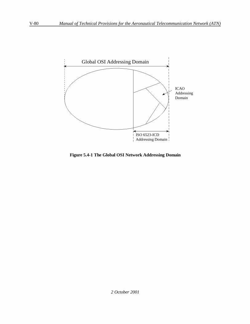
V-80 Manual of Technical Provisions for the Aeronautical Telecommunication Network (ATN)
2 October 2001
Global OSI Addressing Domain
ISO 6523-ICDAddressing Domain
ICAOAddressingDomain
Figure 5.4-1 The Global OSI Network Addressing Domain

Internet communications service V-81
2 October 2001
5.4.3 Network Layer Addressing
5.4.3.1 NSAP Addresses and Network Entity Titles (NETs)
Note 1.— The NSAP Address is formally defined in ISO/IEC 8348. It is the name of a NetworkService Access Point (NSAP) located in an End System, and uniquely identifies that NSAP. It is also anaddress that may be used to find that NSAP.
Note 2. — The Network Entity Title (NET) is also formally defined in ISO/IEC 8348 and is the nameof a Network Entity located within an End or Intermediate System. NETs are syntactically identical to NSAPAddresses and are allocated from the same address space. An NET is also an address that may be used tofind the Network Entity.
Note 3.— An NSAP Address Prefix is a substring of an NSAP Address or NET that is comprised ofthe first ‘n’ characters of the NSAP Address or NET.
5.4.3.2 Network Addressing Domains
Note 1.— A Network Addressing Domain comprises all NSAP Addresses and NETs with a commonNSAP Address Prefix, and is always a sub-domain of the Global NSAP Addressing Domain which containsall NSAP Addresses. This nesting of network addressing domains within the Global Network AddressingDomain is conceptually illustrated in Figure 5.4-1.
Note 2.— A Network Addressing Domain has a single Administrator responsible for the assignmentof NSAP Addresses and NSAP Address Prefixes within the domain. A Network Addressing Domain is oftensub-divided into a number of sub-ordinate domains each characterised by a unique NSAP Address Prefix.Management of such sub-ordinate Network Addressing Domains may then be devolved to anotherAdministrator.
5.4.3.2.1 An ATSC Network Addressing Domain shall be a Network Addressing Domain administeredby an ATSC authority.
5.4.3.2.2 An AINSC Network Addressing Domain shall bea Network Addressing Domain administeredby a member of the Aeronautical Industry.
5.4.3.2.3 ATN End Systems or Intermediate Systems located on-board general aviation aircraft shallbelong to an ATSC Network Addressing Domain, whereas ATN systems installed on-board commercialaircraft shall belong to an AINSC Network Addressing Domain.

V-82 Manual of Technical Provisions for the Aeronautical Telecommunication Network (ATN)
2 October 2001
5.4.3.3 The Syntax of an NSAP Address
Note 1.— Following ISO/IEC 10589, a Router interprets an NSAP Address as a three-fields bitstring. This is illustrated in Figure 5.4-2 below.
Area Address System Identifier SEL
Figure 5.4-2 ISO/IEC 10589 NSAP Address Syntax
Note 2.— An Area Address is typically common to all NSAP Addresses and NETs assigned tosystems in a single Routing Area.
Note 3.— An Area Address is an example of an NSAP Address Prefix.
Note 4.— A System Identifier uniquely identifies an End or Intermediate System within a RoutingArea.
Note 5.— A Selector (SEL) identifies a Network Service User or the Network Entity within an Endor Intermediate System.
5.4.3.4 The ATN Addressing Plan
Note 1.— ISO/IEC 8348 has specified how the Global Network Addressing Domain is broken downinto a number of sub-ordinate Network Addressing Domains, each of which is identified by a uniqueidentifier that forms the initial part of all NSAP Addresses and NETs in those sub-ordinate domains. Thisinitial part is known as the Initial Domain Part (IDP). The IDP itself is defined as comprising two parts: anAuthority Format Identifier (AFI) and an Initial Domain Identifier (IDI). The AFI identifies the format andallocation procedures for the IDI and the format of the remainder of the NSAP Address.
Note 2.— The ATN Network Addressing Domain is such a sub-ordinate Network Addressing Domainand has an IDP that uses an ISO 6523-ICD IDI.
Note 3.— The IDP is always expressed as decimal digits. However, ISO/IEC 8348 permits NSAPAddresses in an ISO 6523-ICD domain to have either a binary or a decimal format for the remainder of theaddress - the Domain Specific Part (DSP). The format of the DSP is determined by the AFI.
5.4.3.4.1 All ATN NSAP Addresses shall have an AFI with the value 47 decimal.
Note.— This AFI value is defined by ISO/IEC 8348 to imply an ISO 6523-ICD IDI with a binaryformat DSP.
5.4.3.4.2 All ATN NSAP Addresses shall have an IDI value of 0027 decimal.

Internet communications service V-83
2 October 2001
Note.— This value has been allocated by ISO to ICAO under the ISO 6523-ICD scheme. An IDP of470027 therefore forms the common NSAP Address Prefix to all ATN NSAP Addresses and effectively definesthe ATN Network Addressing Domain, as a sub-domain of the Global Network Addressing Domain.
5.4.3.5 The Reference Publication Format
Note.— The Reference Publication Format is defined by ISO/IEC 8348 for the publication of NSAPAddresses and NETs in a form suitable for text documents.
5.4.3.5.1 Recommendation.— For the purposes of publication in a text format, ATN NSAP Addressesand NETs should be written as the character sequence “470027+”, identifying the common prefix for allATN NSAP Addresses, followed by the DSP expressed as a sequence of hexadecimal characters.
Note.— The “+” sign is used as a separator between the decimal syntax IDP and the hexadecimalsyntax DSP.
5.4.3.5.2 Each successive pair of hexadecimal digits shall correspond to the next binary octet of theDSP.
5.4.3.6 The ATN NSAP Address Format
Note 1.— The derivation of the ATN NSAP Address Format is illustrated in Figure 5.4-3. This startswith the AFI and IDI fields required by ISO/IEC 8348. It ends with the System ID (SYS) and SEL fieldsrequired by ISO/IEC 10589. The remaining DSP fields are specified below and used to co-ordinate theallocation of ATN NSAP Addresses.
Note 2.— The VER field is used to partition the ATN Addressing Domain into a number ofsub-ordinate addressing domains, each of which provides a different approach to address management.
Note 3.— The ADM field is then used to break down each such partition into a number ofsub-ordinate addressing domains, each of which may then be managed by a different manager.
Note 4.— In Fixed Network Addressing Domains, the ARS field may then be used to identify aNetwork Addressing Domain that will correspond to each Routing Domain under the control of each suchmanager, and the LOC field may then be used to identify each Routing Area within each Routing Domain.
Note 5.— In Mobile Network Addressing Domains, the ARS field identifies an aircraft. Where allATN systems onboard an aircraft form a single Routing Domain, the ARS field also identifies the AddressingDomain that will correspond to that Routing Domain, and the LOC field is used as above. However, whenthe ATN systems onboard a single aircraft form more than one Routing Domain, then part of the LOC fieldis also used to identify such an Addressing Domain.
Note 6.— The reason for the existence of the RDF field is historical.

V-84 Manual of Technical Provisions for the Aeronautical Telecommunication Network (ATN)
2 October 2001
5.4.3.7 NSAP Address Encoding
Note 1.— In ISO/IEC 8348 terms, the IDP has an abstract decimal syntax, and the DSP has anabstract binary syntax. The reason for the use of the word abstract is to emphasise the fact that the actualencoding is outside of the scope of ISO/IEC 8348, and instead is the responsibility of the standards thatspecify the encoding of network layer protocols.
Note 2.— ISO/IEC 8348 does, however, describe two possible encoding schemes, the “preferredbinary encoding” and the “preferred decimal encoding”. ISO/IEC 8473 mandates the use of the preferredbinary encoding for CLNP, while ISO/IEC 10747 mandates a modified version of the preferred binaryencoding in order to cope with bit aligned NSAP Address Prefixes.
Note 3.— In consequence, this specification only specifies how each field of the DSP is allocatedas an unsigned binary number. The actual encoding of the resulting bitstring in an NPDU is then accordingto the applicable protocol specification.

Internet communications service V-85
2 October 2001
IDPAFI IDI DSP
ISO/IEC 8348 NSAP Address Format
ISO/IEC 10589 NSAPAddress Interpretation
Area Address System IDSEL
AFI IDI VER ADM RDF ARS LOC SYS SEL
e.g. 470027+8147455200000000100020A55FFABCDE00
AFI IDI DSP
ATN NSAPAddressFormat
ExampleNSAPAddress
Figure 5.4-3 Derivation of the ATN NSAP Address Format
5.4.3.8 Allocation of the DSP
Note.— The DSP fields of an ATN NSAP Address are the VER, ADM, RDF, ARS, LOC, SYS and SELfields. The size of each of these fields is given in Table 5.4-1.
5.4.3.8.1 The Version (VER) Field
Note 1.— The purpose of the VER field is to partition the ATN Network Addressing Domain into anumber of sub-ordinate Addressing Domains.
Note 2.— The values currently specified for the VER Field and the Network Addressing Domainsso defined, are summarised in Table 5.4-2.
5.4.3.8.1.1 The VER Field shall be one octet in length.
5.4.3.8.1.2 A VER field value of [00000001] shall be used for all NSAP Addresses and NETs in theNetwork Addressing Domain that comprises all Fixed AINSC NSAP Addresses and NETs.
Note.— The NSAP Address Prefix “470027+01” is therefore the common NSAP Address Prefix forthe Fixed AINSC Network Addressing Domain.

V-86 Manual of Technical Provisions for the Aeronautical Telecommunication Network (ATN)
2 October 2001
5.4.3.8.1.3 A VER field value of [0100 0001] shall be used for all NSAP Addresses and NETs in theNetwork Addressing Domain that comprises all Mobile AINSC NSAP Addresses and NETs.
Note.— The NSAP Address Prefix “470027+41” is therefore the common NSAP Address Prefix forthe Mobile AINSC Network Addressing Domain.
Address FieldName
Address Field Size
VER 1 Octet
ADM 3 Octets
RDF 1 Octet
ARS 3 Octets
LOC 2 Octets
SYS 6 Octets
SEL 1 Octet
Table 5.4-1 DSP NSAP Address Field Sizes
5.4.3.8.1.4 A VER field value of [1000 0001] shall be used for all NSAP Addresses and NETs in theNetwork Addressing Domain that comprises all Fixed ATSC NSAP Addresses and NETs.
Note.— The NSAP Address Prefix “470027+81” is therefore the common NSAP Address Prefix forthe Fixed ATSC Network Addressing Domain.
5.4.3.8.1.5 A VER field value of [1100 0001] shall be used for all NSAP Addresses and NETs in theNetwork Addressing Domain that comprises all Mobile ATSC NSAP Addresses and NETs.
Note.— The NSAP Address Prefix “470027+C1” is therefore the common NSAP Address Prefix forthe Mobile ATSC Network Addressing Domain.
5.4.3.8.1.6 All other VER field values shall be reserved.
VER Field Value Network Addressing Domain Common NSAPAddress Prefix for
Domain
[0000 0001] Fixed AINSC 470027+01
[0100 0001] Mobile AINSC 470027+41
[1000 0001] Fixed ATSC 470027+81
[1100 0001] Mobile ATSC 470027+C1
Table 5.4-2 VER Field Assigned Values

Internet communications service V-87
2 October 2001
5.4.3.8.2 The Administration (ADM) Field
5.4.3.8.2.1 General
Note.— The purpose of the ADM field is to sub-divide each of the Network Addressing Domainsintroduced by the VER field into a further set of sub-ordinate Network Addressing Domains, and to permitdevolved administration (i.e. address allocation) of each resulting domain to an individual State orOrganisation.
5.4.3.8.2.1.1 The ADM field shall be three octets in length.
5.4.3.8.2.2 Fixed AINSC NSAP Addresses and NETs
Note.— In the Fixed AINSC Network Addressing Domain, the ADM field is used to sub-divide thisAddressing Domain into a number of sub-ordinate Network Addressing Domains, each of which comprisesNSAP Addresses and NETs for fixed systems operated by a single AINSC Organisation.
5.4.3.8.2.2.1 Allocation of NSAP Addresses and NETs in each such Network Addressing Domainsubordinate to the Fixed AINSC Network Addressing Domain shall be the responsibility of the organisationidentified by the value of the ADM field.
5.4.3.8.2.2.2 Recommendation.— The field value should be derived from the set of three-characteralphanumeric symbols representing an IATA Airline or Aeronautical Stakeholder Designator, according to5.4.1.4.
Note.— AINSC Organisations are intended to register their ADM values with IATA.
5.4.3.8.2.3 Fixed ATSC NSAP Addresses and NETs
Note.— In the Fixed ATSC Network Addressing Domain, the ADM field is used to sub-divide thisAddressing Domain into a number of sub-ordinate Network Addressing Domains, each of which comprisesNSAP Addresses and NETs for fixed systems operated by a single State or within an ICAO Region.
5.4.3.8.2.3.1 Allocation of NSAP Addresses and NETs in each such Network Addressing Domainsubordinate to the Fixed ATSC Network Addressing Domain shall be the responsibility of the State or ICAORegion identified by the value of the ADM field.
5.4.3.8.2.3.2 When used for identifying a State, the ADM field shall be derived from the State’sthree-character alphanumeric ISO 3166 Country Code, represented as upper case characters.
5.4.3.8.2.3.3 In this case, the value of the field shall be determined according to 5.4.1.4.

V-88 Manual of Technical Provisions for the Aeronautical Telecommunication Network (ATN)
2 October 2001
Note.— For example, the encoding of ‘GBR’ is 474252 in hexadecimal. Therefore the NSAP AddressPrefix 470027+81474252 is the common NSAP Address Prefix for all NSAP Addresses and NETs in the UKFixed ATSC Network Addressing Domain.
5.4.3.8.2.3.4 When used to identify an ICAO Region, the first octet of the ADM field shall identify theICAO Region, according to Table 5.4-3, while the values of the remaining two octets shall be assigned by theidentified ICAO Region.

Internet communications service V-89
2 October 2001
Note 1.— The ISO 3166 character codes are always represented as binary octets, each of which hasa zero most significant bit. Therefore, it is possible to guarantee that the field values listed in Table 5.4-3do not conflict with ISO 3166 derived State Identifiers.
ADM Field First Octet ICAO Region[1000 0000] Africa
[1000 0001] Asia
[1000 0010] Caribbean
[1000 0011] Europe
[1000 0100] Middle East
[1000 0101] North America
[1000 0110] North Atlantic
[1000 0111] Pacific
[1000 1000] South America
Table 5.4-3 ICAO Region Identifiers
Note 2.— This Addressing Plan enables ICAO Regions to allocate ADM field values in the FixedATSC Network Addressing Domain to States and Organisations within the ICAO Region, in a structuredmanner. This is in order to permit the efficient advertisement of routing information. For example, in theadvertisement of routes to ‘all RDs in the same ATN Island’ as recommended in 5.3.7.1.4.2.
5.4.3.8.2.3.5 All ADM field values in the Fixed ATSC Network Addressing Domain that do not correspondto valid ISO 3166 Country Codes or which are not assigned to ICAO Regions shall be reserved.
5.4.3.8.2.4 Mobile NSAP Addresses and NETs
Note.— In both the Mobile AINSC and the Mobile ATSC Network Addressing Domains, the ADMfield is used to sub-divide this Addressing Domain into a number of sub-ordinate Network AddressingDomains, each of which comprises NSAP Addresses and NETs for mobile systems operated by a singleAirline or onboard the General Aviation aircraft of a single State.
5.4.3.8.2.4.1 For Mobile AINSC NSAP Address and NETs, the ADM field value shall be set according to5.4.3.8.2.2, and thecorresponding sub-ordinateNetwork Addressing Domain administered by the organisationidentified by the value of the ADM field.
5.4.3.8.2.4.2 For Mobile ATSC NSAP Address and NETs, the ADM field value shall be set according to5.4.3.8.2.3, and the corresponding sub-ordinate Network Addressing Domain administered by the Stateidentified by the value of the ADM field.

V-90 Manual of Technical Provisions for the Aeronautical Telecommunication Network (ATN)
2 October 2001
5.4.3.8.3 The Routing Domain Format (RDF) Field
Note 1.— There is no absolute requirement for the remainder of the DSP in each of the abovedefined Network Addressing Domains to be allocated according to a co-ordinated addressing plan, or foreven the same fields to exist, or the NSAP Addresses to have the same length. However, in order to encouragecommon equipment development, this specification specifies the existence, size and use of the RDF, ARS andLOC fields.
Note 2.— The reason for the existence of the RDF field is historical.
5.4.3.8.3.1 The RDF field shall be one octet in length and its value shall be [0000 0000] in binary.
5.4.3.8.3.2 All other values shall be reserved.
5.4.3.8.4 The Administrative Region Selector (ARS) Field
Note 1.— In Fixed Network Addressing Domains, the purpose of the ARS field is to distinguishRouting Domains or Routing Domains and subordinated Routing Areas respectively operated by the sameState or Organisation.
Note 2.— In Mobile Network Addressing Domain, the purpose of the ARS field is to identify theaircraft on which the addressed system is located. When the systems onboard an aircraft form a singleRouting Domain, then the ARS field also identifies the Routing Domain. When the systems onboard anaircraft form multiple RDs, then part of the LOC field is used to distinguish them.
5.4.3.8.4.1 The ARS field shall be three octets in length.
5.4.3.8.4.2 In theFixed AINSC and ATSC Network Addressing Domains, thevalueof the ARS field shallbe a 24-bit unsigned binary number which is used to uniquely identify a Routing Domain or a Routing Domainand a subordinated Routing Area respectively.
Note.— A State or Organisation may choose to use either the most significant 8 bits, the mostsignificant 16 bits or all 24 bits of the ARS field to uniquely distinguish its Routing Domains.
5.4.3.8.4.3 In the case that the body responsible for the assignment of the ARS field chooses to use onlythe leading bits of the ARS field to distinguish its Routing Domains, the remaining part of the ARS field shall,together with the LOC field (see 5.4.3.8.5), be used to uniquely identify the Routing Areas within thoseRoutingDomains.

Internet communications service V-91
2 October 2001
5.4.3.8.4.4 In the Fixed AINSC and ATSC Network Addressing Domains, the State or Organisationidentified by the value of the ADM field shall be responsible for assigning the ARS field.
Note1.— For example, 470027+8147425200000000 and 470027+8147425200000001 are thereforeNSAP Address Prefixes common to all NSAP Addresses and NETs assigned to fixed systems in two distinctRouting Domains operated by the UK ATSC authority.
Note 2.— Where necessary, the allocation of NSAP Addresses and NETs may thus readily bedelegated to a Network Administrator responsible for each Network Addressing Domain that correspondsto each Routing Domain.
5.4.3.8.4.5 In Mobile AINSC and ATSC Network Addressing Domains, the value of the ARS field shallbe the 24-bit ICAO Aircraft Address that uniquely identifies the NSAP Addresses and NETs in a singleRouting Domain.
Note 1.— If the aircraft is operated by an IATA Airline then the NSAP Address or NET is in a MobileAINSC Network Addressing Domain.
Note 2.— For General Aviation Aircraft, the NSAP Address or NET is in a Mobile ATSC NetworkAddressing Domain.
5.4.3.8.5 The Location (LOC) Field
Note 1.— In Fixed Network Addressing Domains, the purpose of the LOC field is to distinguishRouting Areas within the same Routing Domain.
Note 2.— In Mobile Network Addressing Domains, the LOC field is used
a) to distinguish Routing Areas within the same Mobile Routing Domain, or,
b) when more than one Routing Domain is located on a single Aircraft, to distinguisheach Routing Domain and the Routing Areas contained within them.
Note 3.— For example, the first octet of the LOC field may be used to distinguish each RoutingDomain on board a single aircraft, and the second octet to distinguish each Routing Area.
Note 4.— The combination of AFI, IDI, VER, ADM, RDF, ARS and LOC fields therefore forms anArea Address.

V-92 Manual of Technical Provisions for the Aeronautical Telecommunication Network (ATN)
2 October 2001
5.4.3.8.5.1 The LOC field shall be two octets in length and may be given any binary value.
5.4.3.8.5.2 Theadministrator of theNetwork Addressing Domain that co-incides with theRouting Domainin which a given Routing Area is located, shall be responsible for the allocation of a LOC field value thatprovides a unique Area Address for that Routing Area.
Note.— For example, 470027+81474252000000010045 is an Area Address in a Routing Domainoperated by the UK ATSC Administration.
5.4.3.8.6 The System Identifier (SYS) Field
Note.— ISO/IEC 10589 defines the System Identifier as a variable length field which uniquelyidentifies an End or Intermediate System within a ISO/IEC 10589 Routing Area. Within a Routing Area, allSystem Identifiers are of the same length, although a Router is not able to make assumptions about the lengthof this field outside of its own Routing Area. However, the ATN Addressing Plan does specify this field toalways be six octets in length in order to encourage a common equipment base.
5.4.3.8.6.1 In an ATN NSAP Address or NET, the System Identifier (SYS field) shall be six octets inlength.
5.4.3.8.6.2 The value of the SYS field shall be a unique binary number assigned by the addressingauthority responsible for the Network Addressing Domain that corresponds with the Routing Area in whichthe identified system is located.
Note.— If the System is attached to an IEEE 802 Local Area Network (e.g. an Ethernet), then acommon approach is to use the 48-bit LAN address as the value of the SYS field.
5.4.3.8.7 The NSAP Selector (SEL) Field
Note.— The NSAP Selector (SEL) field identifies the End System or Intermediate System networkentity or network service user process responsible for originating or receiving Network Service Data Units(NSDUs).
5.4.3.8.7.1 The SEL field shall be one octet in length.
5.4.3.8.7.2 The SEL field value for an Intermediate System network entity shall be [0000 0000], exceptfor the case of an airborne Intermediate System implementing the procedures for the optional non-use of IDRP.

Internet communications service V-93
2 October 2001
5.4.3.8.7.3 In the case of an airborne Intermediate System implementing the procedures for the optionalnon-use of IDRP, the SEL field value shall be [1111 1110].
5.4.3.8.7.4 The SEL field value [1111 1111] shall be reserved.
Note 1.— In an Intermediate System, any other SEL field value may be assigned to NSAPs. Theactual value chosen is a local matter.
Note 2.— SEL field values in stand-alone End Systems (i.e. in End Systems not co-located withIntermediate Systems) are not constrained.
5.4.3.8.7.5 SEL field values other than those defined for Intermediate System Network Entities in5.4.3.8.7.2 and 5.4.3.8.7.3 above or being reserved, shall be assigned by the addressing authority responsiblefor the identified End or Intermediate System.
5.4.3.9 Pre-Defined NSAP Address Prefixes
5.4.3.9.1 All AINSC Mobiles
5.4.3.9.1.1 The NSAP Address Prefix 470027+41 shall provide a common NSAP Address Prefix for allAINSC Mobiles.
5.4.3.9.2 All ATSC Mobiles
5.4.3.9.2.1 The NSAP Address Prefix 470027+C1 shall provide a common NSAP Address Prefix for allATSC Mobiles.
Note.— The NLRI for the Default Route to all Mobiles comprises both the NSAP Address Prefixesdefined above.
5.4.3.9.3 All Aircraft Belonging to an Airline
5.4.3.9.3.1 The NSAP Address Prefix 470027+41 plus the value of the ADM field assigned to the airlineshall provide a common NSAP Address Prefix for all AINSC Mobiles operated by a single airline.
Note.— The NLRI for the Route to the “Home” for the aircraft belonging to a given airline containsthis NSAP Address Prefix.

V-94 Manual of Technical Provisions for the Aeronautical Telecommunication Network (ATN)
2 October 2001
5.4.3.9.4 All General Aviation and Other Types of Aircraft Registered by a State
5.4.3.9.4.1 The NSAP Address Prefix 470027+C1 plus the value of the ADM field assigned to the Stateshall provide a common NSAP Address Prefix for all ATSC Mobiles registered by a single State.
Note.— The NLRI for the Route to the “Home” for the General Aviation and other types of aircraftregistered by a single State contains this NSAP Address Prefix.

Internet communications service V-95
2 October 2001
5.5 TRANSPORT SERVICE AND PROTOCOL SPECIFICATION
5.5.1 General
5.5.1.1 Overview
5.5.1.1.1 The COTP (Connection Oriented Transport Protocol ) shall be used to provide an end-to-endreliable data transfer service between Transport Service users on two ATN End Systems.
5.5.1.1.2 In ATN End Systems, the implementation of the COTP shall conform to ISO/IEC 8073 andthe mandatory requirements given in this Chapter.
5.5.1.1.3 The CLTP (Connectionless Mode Transport Protocol) shall be used to provide aconnectionless data transfer service between Transport Service users on two ATN End Systems.
5.5.1.1.4 In ATN End Systems, the implementation of the CLTP shall conform to ISO/IEC 8602 andthe mandatory requirements given in this chapter.
Note.— The transport protocols specified for use in ATN End Systems provide both ConnectionMode and Connectionless Mode communication services. The implementation and use of a particular modeof the Transport Layer service depends on the requirements of the application(s) supported by a given ATNEnd System.
5.5.1.2 Transport Service Description
Note 1.— When the TS-user requires use of the connection mode transport service the TS-user willprovide the following information to the TS-provider on a per Transport Connection basis:
a) called and calling TSAP address;
b) whether or not the expedited data option is required;
c) the required residual error rate (RER) to determine whether use or non-use of thetransport checksum is required, or whether the extended 32-bit checksum is to beused;
d) the Application Service Priority to be mapped into the resulting CLNP NPDUsaccording to Table 1-2;
e) the ATN Security Label specifying the ATN Traffic Type, i.e.
C ATN Operational Communications;C ATN Administrative Communications;C General Communications;C ATN Systems Management Communications.

V-96 Manual of Technical Provisions for the Aeronautical Telecommunication Network (ATN)
2 October 2001
Note 2.— In the case where the Traffic Type specified is ATN Operational Communications theTS-user will additionally provide the traffic category, i.e. Air Traffic Services Communications (ATSC) orAeronautical Operational Control (AOC).
Note 3.— In the case of the ATSC traffic category the TS-user will further specify the required ATSCClass as defined in Table 1-1, or no traffic type policy preference.
Note 4.— In the case of the AOC traffic category the TS-user will further specify the subnetworkpreference (including no preference).
Note 5.— The ATN Traffic Types and their associated traffic categories are specified in Table 5.6-1.The encoding of the ATN Security Label is specified in Figure 5.6-1 and 5.6.2.2.2.2 bullet b).
Note 6.— The TS-user is not required to specify any other Transport Service Quality of Serviceparameters.
5.5.1.3 Transport Service Access Point Addresses
5.5.1.3.1 A TSAP address shall comprise two elements, a NSAP address and a TSAP selector.
5.5.1.3.2 The NSAP address and the TSAP selector shall conform to the provisions in 5.4.
5.5.1.4 Exchange of Transport-Selector parameters
Note.— TSAP Selectors are transmitted in Calling and Called Transport-Selector parameters inCOTP, and in Source and Destination Transport-Selector parameters in CLTP.
5.5.1.4.1 The transport entity shall support Transport-Selector parameters to accommodate the ATNTSAP selector syntax and encoding requirements as specified in 5.4.
5.5.1.4.2 Recommendation.— The transport entity should support remote Transport-Selectorparameters of variable size from 0 up to 32 octets using any encoding and any value.
Note.— The absence of a Calling and Called Transport-Selector assumes the Network Address aloneunambiguously defines the Transport Address.
5.5.1.4.3 In COTP, on receipt of CR (Connection Request) TPDU, the absence of a Calling or CalledTransport-Selector shall be treated as equivalent to a zero length Calling or Called Transport-Selector.
5.5.1.4.4 Theabsenceof a Calling or Called Transport-Selector in a received CC (Connection Confirm)TPDU shall indicate that Calling or Called Transport-Selector is equivalent to the corresponding parameterspecified in the sent CR TPDU.
5.5.1.4.5 When present in a received CC TPDU, Calling and Called Transport-Selector parameters shallbe identical in length and value to the corresponding parameter specified in the sent CR TPDU.

Internet communications service V-97
2 October 2001
5.5.1.4.6 In CLTP, on receipt of UD (User Data) TPDU, the absence of a Source or DestinationTransport-Selector shall be treated as equivalent to a zero length Source or Destination Transport-Selector.

V-98 Manual of Technical Provisions for the Aeronautical Telecommunication Network (ATN)
2 October 2001
5.5.2 Connection Mode Transport Layer Operation
5.5.2.1 Connection Mode Transport Service Primitives
Note 1.— For the purpose of describing the notional interfaces between different OSI protocollayers, each protocol layer is assumed to provide a service to the next higher protocol layer. The assumedservice provided by the ATN transport layer to its user is described in ISO/IEC 8072.
Note 2.— ATN Applications may specify their use of the COTP implemented in ATN End Systemsusing the Transport Service specified in ISO/IEC 8072, including use of ATN priority, and securityparameters as defined in this specification.
Note 3.— There is no requirement to implement the service specified in ISO/IEC 8072 as a softwareinterface.
5.5.2.2 ATN Specific Requirements
5.5.2.2.1 ATN End Systems shall implement the ISO/IEC 8073 Class 4 transport protocol in order toprovide Connection Mode communications over the ATN Internet.
5.5.2.2.2 The COTP shall operate using the CLNS (Connectionless Network Service) as specified in5.6.
Note.— TPDUs (Transport Protocol Data Units) are sent via the N-UNITDATA Request primitive.
5.5.2.2.3 The transport entity shall not concatenate TPDUs from TCs with different transport prioritiesor different Security Labels.
5.5.2.2.4 Recommendation.— The Selective Acknowledgement mechanism should be used forconservation of bandwidth by preventing retransmission of correctly received out-of-sequence TPDUs.
5.5.2.2.5 Recommendation.—The Request of Acknowledgement mechanism should be used to reduceAK traffic.
5.5.2.2.6 Recommendation. — The maximum TPDU size should be at least 1024 octets.
Note.— This is to support efficient transmission of anticipated application dataexchanges.
5.5.2.2.7 Recommendation.—The Transport Layer should propose a TPDU size of at least 1024octets.
5.5.2.2.8 Recommendation.— The Transport Layer should use the TPDU size parameter rather thanthe preferred maximum TPDU size parameter.
5.5.2.2.9 Recommendation.— Implementations of the ATN Transport Layer should propose use ofnormal format in the CR TPDU.

Internet communications service V-99
2 October 2001
5.5.2.2.10 Recommendation.— The Extended format should only be proposed when explicitlynecessary to meet application Quality of Service requirements.
Note.— Because the increased TPDU size resulting from use of extended data TPDU numbering maybe more inefficient, this option is used on a TC only when absolutely required.
5.5.2.2.11 Recommendation.— The Transport Layer should accept non-use of checksum whenproposed in a CR TPDU.
5.5.2.2.12 Implementations of the transport protocol shall support configurable values for all timers andprotocol parameters, rather than having fixed values, in order to allow modification as operational experienceis gained.
5.5.2.2.13 When intended for operation over Air/Ground subnetworks, transport protocolimplementations shall support the minimum - maximum ranges for COTP timer values as presented inTable 5.5-1.
5.5.2.2.13.1 Recommendation.— When intended for operation over Air/Ground subnetworks, thenominal values indicated in Table 5.5-1 should be used to initialize the COTP timers and protocolparameters.
Note.— The Local Retransmission Time (T1) is dynamically updated as a function of the round-triptime measured on a given transport connection (see 5.5.2.8). The recommended algorithms for the dynamiccomputation of the Local Retransmission Time are specified in 5.5.2.8.
5.5.2.2.13.2 Recommendation.— The assignment of initial values for timers and parameters other thanthe nominal values indicated in Table 5.5-1 should be based on operational experience.
5.5.2.2.14 Recommendation.— When intended for operation exclusively over Ground/Groundsubnetworks, implementations of transport protocol timer values should be optimized to ensureinteroperability.
Table 5.5-1 COTP Timer Value Ranges
Name Description Minimum Value Nominal Value Maximum Value
MRL, MLR NSDU Lifetime, seconds 26 400 600
ERL, ELR Maximum Transit Delay,seconds
1 100 150
AL, AR Acknowledgement Time,seconds
0 1 400
T1 Local RetransmissionTime, seconds
2 202 701

V-100 Manual of Technical Provisions for the Aeronautical Telecommunication Network (ATN)
Name Description Minimum Value Nominal Value Maximum Value
2 October 2001
R Persistence Time, seconds 1 405 6310
N Maximum Number ofTransmissions
1 3 10
L Time bound on referenceand/or sequence numbers,seconds
160 1206 7910
I Inactivity Time, seconds 600 4500 6000
W Window Time, seconds 160 4000 5500
Note 1.— In Table 5.5-1, the subscripts “R” and “L” refer to “remote” and “local” respectively.The variable ERL, for example, refers to the maximum transit delay from the remote entity to the local entity.The variable ELR is the maximum transit delay from the local entity to the remote entity. It is assumed thatthese values may be different.
Note 2.— The initial, minimum and maximum values of several of the timers and variables listed inTable 5.5-1 may not be directly configurable. They may be determined based on the relationships definedin clause 12.2.1.1 of ISO/IEC 8073.
5.5.2.3 Connection Mode Transport Quality of Service
5.5.2.3.1 Connection Mode Transport Priority
5.5.2.3.1.1 The Transport Layer shall allow a TC (Transport Connection) priority in the range [0 - 14]
5.5.2.3.1.2 The Transport Layer shall not alter the proposed TC priority specified by the TS-user.
5.5.2.3.1.3 The Transport Layer shall treat all connections without expressed priority as being at thedefault TC priority.
5.5.2.3.1.4 The default TC priority shall be the lowest priority, i.e. priority[14].
5.5.2.3.1.5 When a TS-user specifies a TC priority, the relationship between this TC priority and theCLNP priority shall be as specified in Table 1-2.
5.5.2.3.2 Connection Mode Transport Security
Note.— The ATN security mechanism does not make use of the ISO/IEC 8073 Protection parameter.The support of the Protection parameter is therefore optional.
5.5.2.3.2.1 The Transport Layer shall allow a TS-user to specify a Security Label for a transportconnection. The transport security procedure shall be implemented as specified in 5.2.7.3.1.
Internet communications service V-101
2 October 2001
5.5.2.3.2.2 The Security Label format shall be according to 5.2.7.1. The Transport Layer shall not alterthe Security Label specified by the TS-user.
Note.— When no Security Label is present, a ‘General Communications’ traffic type is implied. Inthis case, CLNP NPDUs are generated without the Security parameter.
5.5.2.3.3 Connection Mode Residual Error Rate
Note.— Three qualitative levels of RER are defined for use with the connection mode transportservice. These correspond to no checksums, the use of the 16-bit checksum specified in ISO/IEC 8073, andthe use of the extended 32-bit checksum described in this specification.
5.5.2.3.3.1 The Transport Layer shall allow a TS-user to specify a Residual Error Rate as threequalitative levels, i.e. low, medium and high.
5.5.2.3.3.2 When supported, a low Residual Error Rate shall correspond to the use of the extended 32-bitchecksum described in 5.5.4. Otherwise, a low residual error rate shall be equivalent to a medium ResidualError Rate.
5.5.2.3.3.3 A medium Residual Error Rate shall correspond to the use of the 16-bit TPDU checksumspecified in ISO/IEC 8073.
5.5.2.3.3.4 A high Residual Error Rate shall correspond to non-use of any transport layer checksum.
5.5.2.4 Encoding of Transport Protocol Data Units
5.5.2.4.1 General
5.5.2.4.1.1 The encoding of TPDUs shall conform to ISO/IEC 8073 for the COTP.
5.5.2.4.2 Encoding of the Acknowledgment Time Parameter
5.5.2.4.2.1 In ATN compliant systems, the acknowledgement time parameter of the CR and CC TPDUsshall be encoded as follows:
Parameter Code: 1000 0101
Note 1.— This is identical to the ISO/IEC 8073 standardparameter.
Parameter Length: 2 or 3 octets.
Parameter Value: Acknowledgment Timer (AL) value expressed in milliseconds (perISO/IEC 8073 standard)

V-102 Manual of Technical Provisions for the Aeronautical Telecommunication Network (ATN)
2 October 2001
Note 1.— This enhancement is in response to the unique requirements of the aeronauticalenvironment which may require longer acknowledgment times than foreseen in ISO/IEC 8073.
Note 2.— Initial values of these timers may depend upon the subnetwork, traffic type and routingpolicy requirements expressed in the associated ATN Security Label.
Note 3.— In cases where the AL value is expressed in 2 octets (less than 65536 milliseconds), theATN implementation will behave in compliance with the ISO/IEC 8073 standard.
Note 4.— Implementors are advised to permit systems administrators to readily specify initial values.
5.5.2.4.3 Encoding of the Extended 32-bit Checksum Parameter
5.5.2.4.3.1 The Extended 32-bit Checksum Parameter shall be encoded as a variable part TPDUparameter using the following format:
Parameter Code: 0000 1000, indicating Extended 32-bit Checksum Parameter
Parameter Length: 4
Parameter Value: Result of the checksum algorithm as specified in 5.5.4.5
Note 1.— When supported, the parameter is included in a CR TPDU and is thereafter included inall other TPDUs except when the connection responder indicates non-support of the parameter by omittingit from the variable part of the CC TPDU.
Note 2.— This parameter is not defined by ISO/IEC 8073. However, it is not a protocol error to useit in a CR TPDU as the ISO standard explicitly requires unknown options parameters in CR TPDUs to beignored if unrecognised. Hence, as long as this parameter is only used in other TPDUs when both initiatorand receiver indicate support by including it in the CR TPDU, and in a CC TPDU in response to such a CRTPDU, its implementation will not result in interoperability problems.
Note 3.— Parameter codes with bits 7 and 8 set to zero are explicitly not assigned by ISO/IEC 8073,but nor is their use precluded. It is theoretically possible that another non-ATN implementation may makealternative use of the same parameter code. Such implementations will not be interoperable with ATNimplementations as CR TPDUs containing such a parameter will be ignored as the expected checksum willnot verify as correct.
5.5.2.5 Transport Layer Congestion Avoidance
5.5.2.5.1 General
Note 1.— The congestion avoidance mechanisms in the Transport Layer make use of the notificationby the Network Layer of Congestion Experienced flags in received NPDUs. This mechanism allows transportentities to reduce the window, i.e. the number of DT TPDUs allowed to be sent without acknowledgement,when the proportion of NPDUs indicating congestion reaches a certain threshold.

Internet communications service V-103
2 October 2001
Note 2.— This congestion information consists of the total length of the sequence of NPDUs formingthe associated NSDU, and the number of NPDUs of that sequence that had their congestion experienced flagset upon reception.
Note 3.— Transport Congestion Avoidance measures are applicable to the Connection Modetransport service only.
5.5.2.5.1.1 Thetransport entity shall implement thecongestion avoidancealgorithmdefined in this section.
5.5.2.5.1.2 This algorithm shall be applied for each transport connection individually.
5.5.2.5.2 Advertised Window
5.5.2.5.2.1 General
5.5.2.5.2.1.1 A receiving transport entity shall provide the sending transport entity with the lower windowedge and the size of the advertised window (W) by using the explicit flow control mechanisms specified inISO/IEC 8073.
Note.— Theadvertised windowis the window advertised by the receiver of the data to the senderof the data. It indicates the number of DT TPDUs that the receiver is willing to accept.
5.5.2.5.2.2 Initialisation of the Advertised Window
5.5.2.5.2.2.1 The initial value of the window W0 that is advertised to the sending transport entity shall havea locally configurable value.
5.5.2.5.2.2.2 This initial window shall be sent to the sending transport entity in the first CDT fieldtransmitted.
5.5.2.5.3 Receiving Transport Entity Congestion Avoidance
5.5.2.5.3.1 General
5.5.2.5.3.1.1 Congestion avoidance shall be performed within repeated update phases.
5.5.2.5.3.1.2 Each update phase shall terminate with the possible advertisement of a new window size tothe sending transport entity.
5.5.2.5.3.2 Start of Update Phase
5.5.2.5.3.2.1 An update phase of the advertised window shall start after the receiving transport entity hasadvertised a new value of the window Wnew to the sending transport entity.
5.5.2.5.3.3 Ignoring Congestion Information

V-104 Manual of Technical Provisions for the Aeronautical Telecommunication Network (ATN)
2 October 2001
5.5.2.5.3.3.1 After having advertised a new window size, the receiving transport entity shall ignorecongestion information coming from the Network Layer, until it has received W (i.e. the « old » advertisedwindow size) further DT-TPDUs. It then shall enter the sampling sub-phase.
5.5.2.5.3.3.2 When the sending transport entity advertises the initial window size W0, it shall set W to 0.
5.5.2.5.3.4 Sampling Congestion Information
5.5.2.5.3.4.1 The receiving transport entity shall maintain a count N equal to the total number of NPDUsthat convey DT-TPDUs, and a count NC equal to the number of such NPDUs that had their congestionexperienced flag set upon reception..5.5.2.5.3.4.2 Upon entering the sampling sub-phase, these counts shall be reset to zero.
5.5.2.5.3.4.3 These counts shall be updated upon receipt of a DT-TPDU using the congestion informationsupplied by the Network Layer.
5.5.2.5.3.4.4 Thesampling sub-phaseshall end as soon as the transport entity has received WnewDT-TPDUswithin the sampling sub-phase. The end of the sampling sub-phase also terminates the update phase.
5.5.2.5.3.5 Action Upon the End of the Update Phase
5.5.2.5.3.5.1 The receiving transport entity shall take the following actions at the end of each update phase:
a) If the countNC is less thanλ % of the countN, the receiving transport entity shallincrease the size of the advertised window by addingδ up to a maximum based on thelocal buffer management policy. Otherwise, it shall decrease the size of the advertisedwindow by multiplying it byβ. If the result of this multiplication has a decimal part,the new window size shall be the truncated to its integer value. The size of theadvertised window shall not go to a value smaller than 1.
b) The countsN andNC shall be reset to 0.
c) The new window size shall be transmitted to the sending transport entity inaccordance with the explicit flow control mechanisms specified in ISO/IEC 8073.
Note.— This procedure does not explicitly require the reduction of the upper window edge, as it ispossible to gradually reduce the credit window.
5.5.2.5.4 Recommended Algorithm Values
5.5.2.5.4.1 Recommendation.— Thevaluesettings defined in the following table should be implementedand configurable by a System Manager:
Table 5.5-2. Congestion Avoidance algorithm values
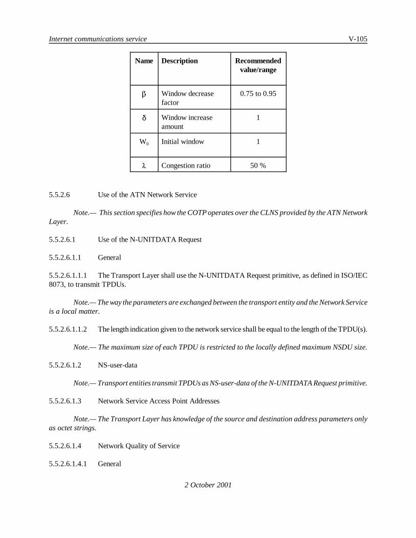
Internet communications service V-105
2 October 2001
Name Description Recommendedvalue/range
$ Window decreasefactor
0.75 to 0.95
δ Window increaseamount
1
W0 Initial window 1
8 Congestion ratio 50 %
5.5.2.6 Use of the ATN Network Service
Note.— This section specifies how the COTP operates over the CLNS provided by the ATN NetworkLayer.
5.5.2.6.1 Use of the N-UNITDATA Request
5.5.2.6.1.1 General
5.5.2.6.1.1.1 The Transport Layer shall use the N-UNITDATA Request primitive, as defined in ISO/IEC8073, to transmit TPDUs.
Note.— The way the parameters are exchanged between the transport entity and the Network Serviceis a local matter.
5.5.2.6.1.1.2 The length indication given to the network service shall be equal to the length of the TPDU(s).
Note.— The maximum size of each TPDU is restricted to the locally defined maximum NSDU size.
5.5.2.6.1.2 NS-user-data
Note.— Transport entities transmit TPDUs as NS-user-data of the N-UNITDATA Request primitive.
5.5.2.6.1.3 Network Service Access Point Addresses
Note.— The Transport Layer has knowledge of the source and destination address parameters onlyas octet strings.
5.5.2.6.1.4 Network Quality of Service
5.5.2.6.1.4.1 General

V-106 Manual of Technical Provisions for the Aeronautical Telecommunication Network (ATN)
2 October 2001
5.5.2.6.1.4.1.1 The COTP shall use the network QoS parameters as defined in the sections below.
5.5.2.6.1.4.2 Network Layer Priority
5.5.2.6.1.4.2.1 TheCOTP shall use thenetwork priority parameter to indicate therelativepriority of a NSDU.
5.5.2.6.1.4.2.2 When a transport priority has been specified, the value of network priority shall be determinedbased on the transport connection priority, as defined in Table 1-2.
5.5.2.6.1.4.2.3 If the Transport Layer supports levels of TC priority numerically greater than 14, TPDUsassociated with the TC shall be transmitted using a network priority level of zero.
Note.— As specified in ISO/IEC 8073, the Transport Layer priority level zero is highest. ISO/IEC8473 specifies zero as the lowest network priority and fourteen as the highest. Table 1-2 defines the requiredmapping between these two schemes for use by ATN systems.
5.5.2.6.1.4.3 Network Layer Security
Note.— The use of the Network Layer security is specified in 5.2.7.3.1.
5.5.2.6.2 Use of the N-UNITDATA Indication
5.5.2.6.2.1 General
5.5.2.6.2.1.1 The Transport Layer shall be capable of receiving TPDUs from the ATN network serviceusing the N-UNITDATA indication primitive, as defined in ISO/IEC 8073.
Note.— The way the parameters are exchanged between the transport entity and the Network Serviceis a local matter.
5.5.2.6.2.2 NS-user-data
Note.— Transport entities receive TPDUs as NS-user-data of the N-UNITDATA Indication primitive.
5.5.2.7 Connection Mode Transport APRL
5.5.2.7.1 Mandatory and Optional Functions
5.5.2.7.1.1 General
Note.— The requirements for the COTP are provided in the form of an ATN Protocol RequirementsList (APRL). The APRL has been prepared using the PICS (Protocol Implementation ConformanceStatement) proforma provided with ISO/IEC 8073.
5.5.2.7.1.1.1 An implementation of the ISO/IEC 8073 Transport Protocol shall be used in an ATN EndSystem if and only if its PICS is in compliance with the APRL provided with these SARPs.

Internet communications service V-107
2 October 2001
5.5.2.7.1.2 Protocol Implementation
5.5.2.7.1.2.1 Classes Implemented
Index Class ISO/IEC 8073References
ISO Status ATN Support
C0 Class 0 14.2 O.1 O
C1 Class 1 14.4 C0:O O
C2 Class 2 14.2 O.1 O
C3 Class 3 14.3 C2:O O
C4 Class 4 operation over CONS 14.3 C2:O O
C4L Class 4 operation over CLNS 14.3 C2:O M
5.5.2.7.1.2.2 Specific ATN Requirements
Index Feature SARPsReference
ATN Support
ATN1 Support of Congestion Avoidance Procedures? 5.5.2.5 M
ATN2 Transport to Network Priority Mapping? 5.5.2.6.1.4.2 M
ATN3 Support of ATN Security Label? 5.5.2.6.1.4.3 M
ATN4 Configurable Transport Timers? 5.5.2.2.12 M
ATN5 Enhanced encoding of Acknowledgment TimeParameter?
5.5.2.4.2 M
ATN6 Support of Extended 32-bit Checksum? 5.5.4 M
ATN7 Dynamic Local Retransmission Time Adaptation? 5.5.2.8 M
5.5.2.7.1.3 Initiator/Responder Capability for Protocol Classes 0-4
Index ISO/IEC 8073References
ISO Status ATN Support
IR1 Initiating CR TPDU 14.5 a) O.2 M

V-108 Manual of Technical Provisions for the Aeronautical Telecommunication Network (ATN)
Index ISO/IEC 8073References
ISO Status ATN Support
2 October 2001
IR2 Responding to CR TPDU 14.5 a) O.2 M
5.5.2.7.1.4 Supported Functions
5.5.2.7.1.4.1 Supported Functions for Class 4 (C4 or C4L::)
5.5.2.7.1.4.1.1 Mandatory Functions for Class 4
Index Function ISO/IEC 8073References
ISO Status ATN Support
T4F1 TPDU transfer 6.2 M M
T4F2 Segmenting 6.3 M M
T4F3 Reassembling 6.3 M M
T4F4 Separation 6.4 M M
T4F5 Connection establishment 6.5 M M
T4F6 Connection refusal 6.6 M M
T4F7 Data TPDU numbering (normal) 6.10 M M
T4F8 Retention and acknowledgement ofTPDUs (AK)
6.13.4.1 M M
T4F9 Explicit flow control 6.16 M M
T4F10 Checksum 6.17 M M
T4F11 Frozen references 6.18 M M
T4F12 Retransmission on time-out 6.19 M M
T4F13 Resequencing 6.20 M M
T4F14 Inactivity control 6.21 M M

Internet communications service V-109
2 October 2001
5.5.2.7.1.4.1.2 Mandatory Functions for Operation over Connectionless Network Service
Index Function ISO/IEC 8073References
ISO Status ATN Support
T4F23 Transmission over CLNS 6.1.2 M M
T4F24 Normal release when operating overCLNS (explicit)
6.7.2 M M
T4F25 Association of TPDUs with transportconnections when operating overCLNS
6.9.2 M M
T4F26 Expedited data transfer whenoperating over CLNS (Networknormal)
6.11.2 M M
T4F27 Treatment of protocol errors whenoperating over CLNS
6.22.2 M M
5.5.2.7.1.4.1.3 ISO/IEC 8073 Optional Functions
Index Feature ISO/IEC 8073References
ISO Status ATN Support
T4F28 Data TPDU numbering (extended) 6.10 O O
T4F29 Non-use of checksum 6.17 O M
T4F30 Concatenation 6.4 O O
T4F31 Retention and acknowledgement ofTPDUsUse of selective acknowledgement
6.13.4.4 O O
T4F32 Retention and acknowledgement ofTPDUsUse of request acknowledgement
6.13.4.3 O O
5.5.2.7.1.5 Supported TPDUs
Index TPDUs ISO/IEC 8073References
ISO Status ATN Support
ST1 CR supported on transmission 13.1 IR1:M M

V-110 Manual of Technical Provisions for the Aeronautical Telecommunication Network (ATN)
Index TPDUs ISO/IEC 8073References
ISO Status ATN Support
2 October 2001
ST2 CR supported on receipt 13.1 IR2:M M
ST3 CC supported on transmission 13.1 IR2:M M
ST4 CC supported on receipt 13.1 IR1:M M
ST5 DR supported on transmission 13.1 IR2:M M
ST6 DR supported on receipt 13.1 IR1:M M
ST7 DC supported on transmission 13.1 C4L:M M
ST8 DC supported on receipt 13.1 C4L:M M
ST9 DT supported on transmission 13.1 M M
ST10 DT supported on receipt 13.1 M M
ST11 ED supported on transmission 13.1 C4L:M MO
ST12 ED supported on receipt 13.1 C4L:M MO
ST13 AK supported on transmission 13.1 C4L:M M
ST14 AK supported on receipt 13.1 C4L:M M
ST15 EA supported on transmission 13.1 C4L:M MO
ST16 EA supported on receipt 13.1 C4L:M MO
ST19 ER supported on receipt 13.1 M M
Note.— The following table states for which classes, if any, ER TPDU is supported on transmission.
Index Class ISO/IEC 8073References
ISO Status ATN Support
SER4L ER support on transmission of Class 4over CLNS
6.22.2 O O

Internet communications service V-111
2 October 2001
5.5.2.7.1.6 Supported Parameters of Issued TPDUs
5.5.2.7.1.6.1 Parameter Values for CR TPDU (C4L::)
Index Feature ISO/IEC 8073Reference
ISO Status ATN Support
ICR1 Bits 8 and 7 in the additional optionsselection parameter of a CR TPDU setto zero?
13.3.4 g) M M
5.5.2.7.1.6.1.1 If the preferred class in the CR is 2,3 or 4:
Index Feature ISO/IEC 8073Reference
ISO Status ATN Support
ICR2 Is class 0 always offered as analternative class?
14.4 O X
5.5.2.7.1.6.2 Supported parameters for Class 4 TPDUs (C4L::)
5.5.2.7.1.6.2.1 Optional Parameters for a Connection Request TPDU
Index Supported parameters ISO/IEC 8073References
ISO Status ATN Support
I4CR7 Called Transport-Selector 13.3.4 a) O M
I4CR8 Calling Transport-Selector 13.3.4 a) O M
I4CR9 TPDU size 13.3.4 b) O O
I4CR10 Version Number 13.3.4 d) O O
I4CR11 Protection parameters 13.3.4 e) O O
I4CR12 Additional option selection 13.3.4 g) O M
I4CR13 Throughput 13.3.4 k) O O
I4CR14 Residual error rate 13.3.4 m) O O
I4CR15 Priority 13.3.4 n) O M
I4CR16 Transit delay 13.3.4 p) O O
I4CR17 Acknowledgement time 13.3.4 j) O M

V-112 Manual of Technical Provisions for the Aeronautical Telecommunication Network (ATN)
Index Supported parameters ISO/IEC 8073References
ISO Status ATN Support
2 October 2001
I4CR18 Preferred maximum TPDU size 13.3.4 c) O O
I4CR19 Inactivity timer 13.3.4 r) O M
5.5.2.7.1.6.2.2 Optional Parameters for a Connection Confirm TPDU
Note 1.— According to ISO, the following parameters are optional if a CC TPDU is issued inclass 4:
Index Supported parameters ISO/IEC 8073References
ISO Status ATN Support
I4CC6 Called Transport-Selector 13.4.4 O M
I4CC7 Calling Transport-Selector 13.4.4 O M
I4CC8 TPDU size 13.4.4 O O
I4CC9 Protection parameters 13.4.4 O O
I4CC10 Additional option selection 13.4.4 O M
I4CC11 Acknowledgement time 13.4.4 O M
I4CC12 Throughput 13.4.4 O O
I4CC13 Residual error rate 13.4.4 O O
I4CC14 Priority 13.4.4 O M
I4CC15 Transit delay 13.4.4 O O
I4CC16 Preferred maximum TPDU size 13.4.4 I4CR18:O O
I4CC17 Inactivity timer 13.4.4 O M
Note 2.— The support of T4F26 implies that the Additional Options Selection parameter ismandatory.
5.5.2.7.1.6.2.3 Optional Parameter for a Disconnect Request TPDU
Index Supported parameter ISO/IEC 8073References
ISO Status ATN Support
I4DR4 Additional information 13.5.4 a) O O

Internet communications service V-113
2 October 2001
5.5.2.7.1.6.2.4 Mandatory Parameter for a Data TPDU
Note.— According to ISO, the following parameter is mandatory in a DT TPDU if request ofacknowledgement has been selected.
Index Supported parameter ISO/IEC 8073References
ISO Status ATN Support
I4DT4 Request of acknowledgement 13.7.3 b) T4F32:M T4F32:M
5.5.2.7.1.6.2.5 Optional Parameter for an Acknowledgement TPDU
Note.— According to ISO, an AK TPDU containing flow control information will be transmitted ifan AK TPDU is received under the conditions specified in ISO/IEC 8073 12.2.3.9. The following parameteris mandatory for ATN compliant systems if an AK TPDU is issued in Class 4.
Index Supported parameter ISO/IEC 8073References
ISO Status ATN Support
I4AK4 Flow control confirmation 13.9.4 c) O M
5.5.2.7.1.6.2.6 Use of the Subsequence Number Parameter in the Acknowledgement TPDU
Note.— According to ISO, if an implementation can reduce credit and does so in the manner outlinedin ISO/IEC 8073 12.2.3.8.2 then the subsequence number in AK TPDU is mandatory.
Index Supported parameters ISO/IEC 8073References
ISO Status ATN Support
I4AK5 Subsequence number 13.9.4. b) O M
5.5.2.7.1.6.2.7 Use of the Selective Acknowledgement Parameter in the Acknowledgement TPDU
Note.— According to ISO, the following parameter is optional in an AK TPDU if selectiveacknowledgement has been negotiated.
Index Supported parameter ISO/IEC 8073References
ISO Status ATN Support
I4AK6 Selective acknowledgementparameters
13.9.4. d) T4F31:O T4F31:O
5.5.2.7.1.6.2.8 Optional Parameters for an Error TPDU
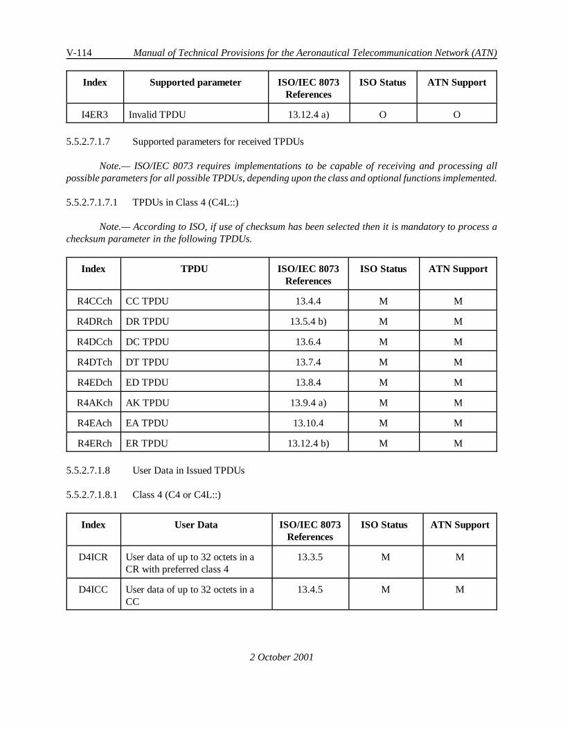
V-114 Manual of Technical Provisions for the Aeronautical Telecommunication Network (ATN)
2 October 2001
Index Supported parameter ISO/IEC 8073References
ISO Status ATN Support
I4ER3 Invalid TPDU 13.12.4 a) O O
5.5.2.7.1.7 Supported parameters for received TPDUs
Note.— ISO/IEC 8073 requires implementations to be capable of receiving and processing allpossible parameters for all possible TPDUs, depending upon the class and optional functions implemented.
5.5.2.7.1.7.1 TPDUs in Class 4 (C4L::)
Note.— According to ISO, if use of checksum has been selected then it is mandatory to process achecksum parameter in the following TPDUs.
Index TPDU ISO/IEC 8073References
ISO Status ATN Support
R4CCch CC TPDU 13.4.4 M M
R4DRch DR TPDU 13.5.4 b) M M
R4DCch DC TPDU 13.6.4 M M
R4DTch DT TPDU 13.7.4 M M
R4EDch ED TPDU 13.8.4 M M
R4AKch AK TPDU 13.9.4 a) M M
R4EAch EA TPDU 13.10.4 M M
R4ERch ER TPDU 13.12.4 b) M M
5.5.2.7.1.8 User Data in Issued TPDUs
5.5.2.7.1.8.1 Class 4 (C4 or C4L::)
Index User Data ISO/IEC 8073References
ISO Status ATN Support
D4ICR User data of up to 32 octets in aCR with preferred class 4
13.3.5 M M
D4ICC User data of up to 32 octets in aCC
13.4.5 M M

Internet communications service V-115
Index User Data ISO/IEC 8073References
ISO Status ATN Support
2 October 2001
D4IDR User data of up to 64 octets in aDR
13.5.5 M M
5.5.2.7.1.9 User Data in Received TPDUs
Index User Data ISO/IEC 8073References
ISO Status ATN Support
DRCC 32 octets of user data in a CCTPDU
13.4.5 IR1:M IR1:M
DRDR 64 octets of user data in a DRTPDU
13.5.5 IR1:M IR1:M
DRCR 32 octets of user data in a CRTPDU
13.3.5 IR2:M IR2:M
5.5.2.7.1.10 Negotiation
Note.— If an option is not returned in the CC, it is considered to have been refused. This allowscompatible negotiation between versions of the ISO/IEC 8073 transport protocol.
5.5.2.7.1.10.1 Class Negotiation - Initiator
Index Feature ISO/IEC 8073References
ATN SupportedValue
NC The preferred class in the CR TPDU maycontain any of the classes supported bythe implementation
6.5.5 j) Class 4
Note 1.— Negotiation of other protocol classes is out of scope. If this is the only profile supportedthen it is not possible to negotiate any other protocol class.
Note 2.— The table below specifies valid alternative classes.
Index Preferred class ISO/IEC 8073References
ISO AllowedValues
ATN SupportedValues
NAC5 Class 4 over CLNS 6.5.5 j) None None
Note 3.— The class cannot be negotiated since Class 4 is the only class allowed over CLNS.

V-116 Manual of Technical Provisions for the Aeronautical Telecommunication Network (ATN)
2 October 2001
5.5.2.7.1.10.2 Class negotiation - responder side
Index Preferred class ISO/IEC 8073References
ISO AllowedResponses
ATN SupportedValues
RC4 What classes can you respond withif CR proposes only class 4?
6.5.4 j) Table 3 2,4 or connec-tion refuseddepending onclassessupported
Class 4
RC4a What classes can you respond withif CR proposes class 4 as preferredclass and the alternative classparameter is present?
6.5.4 j) Table 3 0,1,2,3,4 orconnectionrefuseddepending onclassessupported andcoding ofalternativeclass
Class 4
Note.— This table does not preclude connection refusal for other reasons.
5.5.2.7.1.10.3 TPDU Size Negotiation
Index TPDU size ISO/IEC8073
References
ISOStatus
ATN Support
TS1 If maximum TPDU size is proposed in a CRTPDU then the initiator shall support allTPDU sizes from 128 octets to the maximumproposed
14.6 e) I4CR9:M I4CR9:M
TS2 If the preferred maximum TPDU sizeparameter is used in a CR TPDU then theinitiator shall support all TPDU sizes, except0, that are multiples of 128 octets up to thepreferred maximum proposed
14.6 e) I4CR18:M I4CR18:M

Internet communications service V-117
2 October 2001
Index TPDU size ISO/IEC 8073References
ISO AllowedValues
ATN SupportedValues
TS3 What is the largest value of thepreferred maximum TPDU sizeparameter in a CR TPDU?
14.6 e) any multiple of128 octets
any multiple of128 octets
TS4 What is the largest value of thepreferred maximum TPDU sizeparameter in a CC TPDU?
14.6 e) any multiple of128 octets
any multiple of128 octets
Note.— An implementation of the Transport Layer can support a preferred maximum TPDU sizelarger than 1024 octets.
Index TPDU size ISO/IEC 8073References
ISO AllowedValues
ATN SupportedValues
T4S1 What is the largest value of themaximum TPDU size parameter ina CR TPDU with preferred class4?
14.6 e) One of 128,256, 512, 1024,2048, 4096,8192
One of 128, 256,512, 1024, 2048,4096, 8192
T4S2 What is the largest value of themaximum TPDU size parameterwhich may be sent in the CCTPDU when class 4 is selected?
14.6 e) 128, 256, 512,1024, 2048,4096, 8192
128, 256, 512,1024, 2048, 4096,8192
5.5.2.7.1.10.4 Use of Extended Format
Index Extended format ISO/IEC 8073References
ISO AllowedValues
ATN SupportedValue
NEF3 What formats can you propose inthe CR TPDU in class 4?
6.5.5 n) normal, extended normal,extended
NEF6 What formats can you select in CCwhen extended has been proposedin CR in class 4?
6.5.5 n) normal, extended normal,extended
Note.— This table does not preclude proposal of the extended format.

V-118 Manual of Technical Provisions for the Aeronautical Telecommunication Network (ATN)
2 October 2001
5.5.2.7.1.10.5 Expedited data Transport service
Index Expedited data ISO/IEC 8073References
ISO Status ATN Supported
TED1 Is the expedited data indicationsupported in CR and CC TPDU?
6.5.5 r) M MO
Note.— Expedited data is proposed using the Additional Options Parameters in the CR and CCTPDUs.
5.5.2.7.1.10.6 Non-use of Checksum (C4L and T4F29::)
Index Non-use of checksum ISO/IEC 8073References
ISO AllowedValues
ATN SupportedValues
NUC1 What proposals can you make inthe CR?
6.5.5 p) non-use, use non-use, use
NUC2 What proposals can you make inCC when non-use of checksum hasbeen proposed in CR?
6.5.5 p) non-use, use non-use, use
Note 1.— A Transport Layer is able to propose either use or non-use of checksum in a CR TPDU.
Note 2.— The term “non-use” means that the Transport Layer may respond accepting non-use ofchecksum. A Transport Layer may also respond with use of checksum if non-use has been proposed.
5.5.2.7.1.10.7 Use of selective acknowledgement
Index Selective Acknowledgement ISO/IEC 8073References
ISO Status ATN Support
USA1 Is use of selective acknowledgementproposed in CR TPDUs ?
6.5.5 s) O O
USA2 Is use of selective acknowledgementselected in a CC when it has beenproposed in a CR ?
6.5.5 s) O O
5.5.2.7.1.10.8 Use of Request Acknowledgement
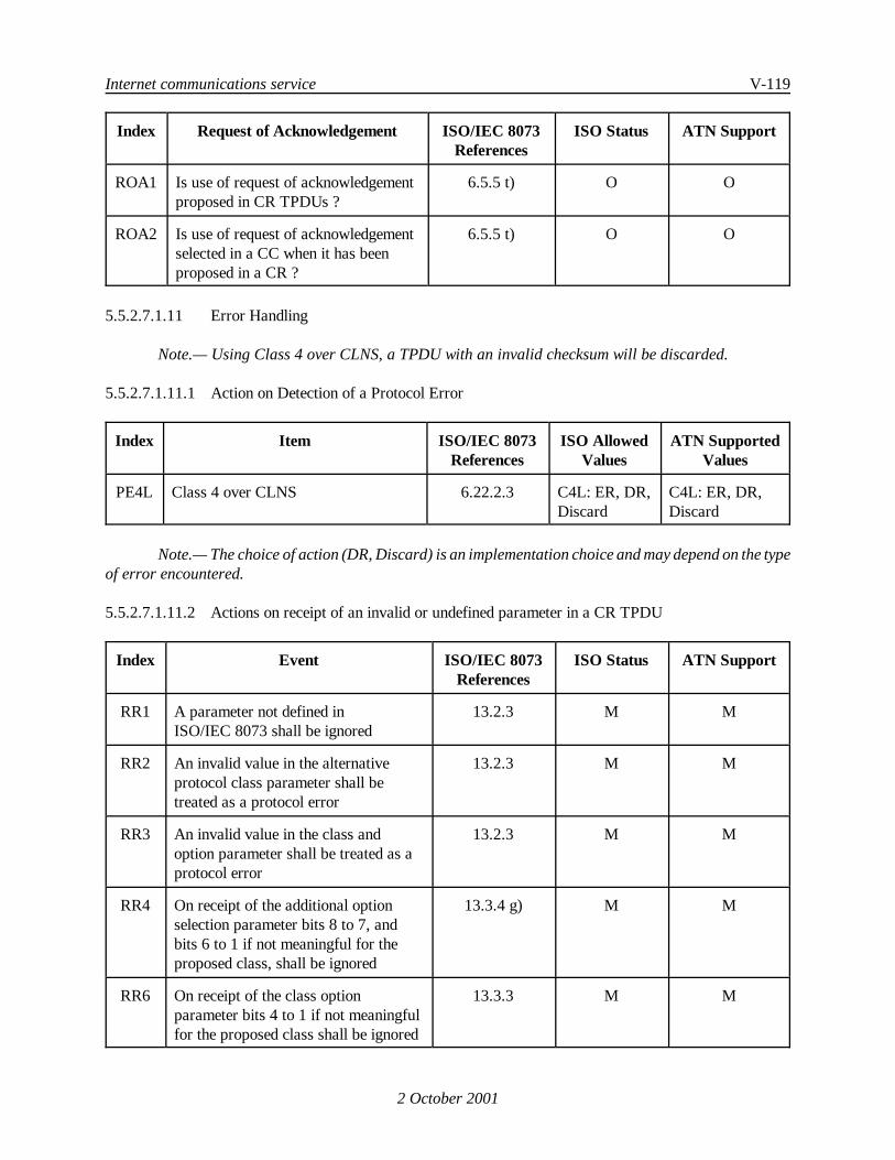
Internet communications service V-119
2 October 2001
Index Request of Acknowledgement ISO/IEC 8073References
ISO Status ATN Support
ROA1 Is use of request of acknowledgementproposed in CR TPDUs ?
6.5.5 t) O O
ROA2 Is use of request of acknowledgementselected in a CC when it has beenproposed in a CR ?
6.5.5 t) O O
5.5.2.7.1.11 Error Handling
Note.— Using Class 4 over CLNS, a TPDU with an invalid checksum will be discarded.
5.5.2.7.1.11.1 Action on Detection of a Protocol Error
Index Item ISO/IEC 8073References
ISO AllowedValues
ATN SupportedValues
PE4L Class 4 over CLNS 6.22.2.3 C4L: ER, DR,Discard
C4L: ER, DR,Discard
Note.— The choice of action (DR, Discard) is an implementation choice and may depend on the typeof error encountered.
5.5.2.7.1.11.2 Actions on receipt of an invalid or undefined parameter in a CR TPDU
Index Event ISO/IEC 8073References
ISO Status ATN Support
RR1 A parameter not defined inISO/IEC 8073 shall be ignored
13.2.3 M M
RR2 An invalid value in the alternativeprotocol class parameter shall betreated as a protocol error
13.2.3 M M
RR3 An invalid value in the class andoption parameter shall be treated as aprotocol error
13.2.3 M M
RR4 On receipt of the additional optionselection parameter bits 8 to 7, andbits 6 to 1 if not meaningful for theproposed class, shall be ignored
13.3.4 g) M M
RR6 On receipt of the class optionparameter bits 4 to 1 if not meaningfulfor the proposed class shall be ignored
13.3.3 M M

V-120 Manual of Technical Provisions for the Aeronautical Telecommunication Network (ATN)
2 October 2001
Index Event ISO/IEC 8073Reference
ISO AllowedValue
ATNSupported
Value
RR7 What action is supported on receipt ofa parameter defined in ISO 8073(other than those covered above) andhaving an invalid value ?
13.2.3 Ignore,Protocol Error
Ignore, ProtocolError
Note.— The choice of action (Ignore, Protocol error) is an implementation choice and may dependon the type of error encountered.
5.5.2.7.1.11.3 Actions on receipt of an invalid or undefined parameter in a TPDU other than a CR TPDU
Index Event ISO/IEC 8073References
ISO Status ATN Support
U11 A parameter not defined in ISO/IEC8073 shall be treated as a protocolerror
13.2.3 M M
U12 A parameter which has an invalidvalue as defined in ISO/IEC 8073shall be treated as a protocol error
13.2.3 M M
U13(class
4 only)
A TPDU received with a checksumwhich does not satisfy the definedformula shall be discarded
6.17.3 M M
5.5.2.7.1.12 Class 4 Timers and Protocol Parameters
Index ISO/IEC 8073References
ISO Status ATN Support
TA1 T1 (Local Retransmission) 12.2.1.1.4 M M
TA2 N (Maximum Transmission) 12.2.1 M M
TA3 IL (Local Inactivity Time) 12.2.1.1.7 M M
TA4 W (Window Update) 12.2.1 M M
TA5 L (Frozen Reference Time) 12.2.1.1.6 M M
Index ISO/IEC 8073References
ISO Status ATN Support
ATN-TA1 R (Persistence) 12.2.1.1.5 O O
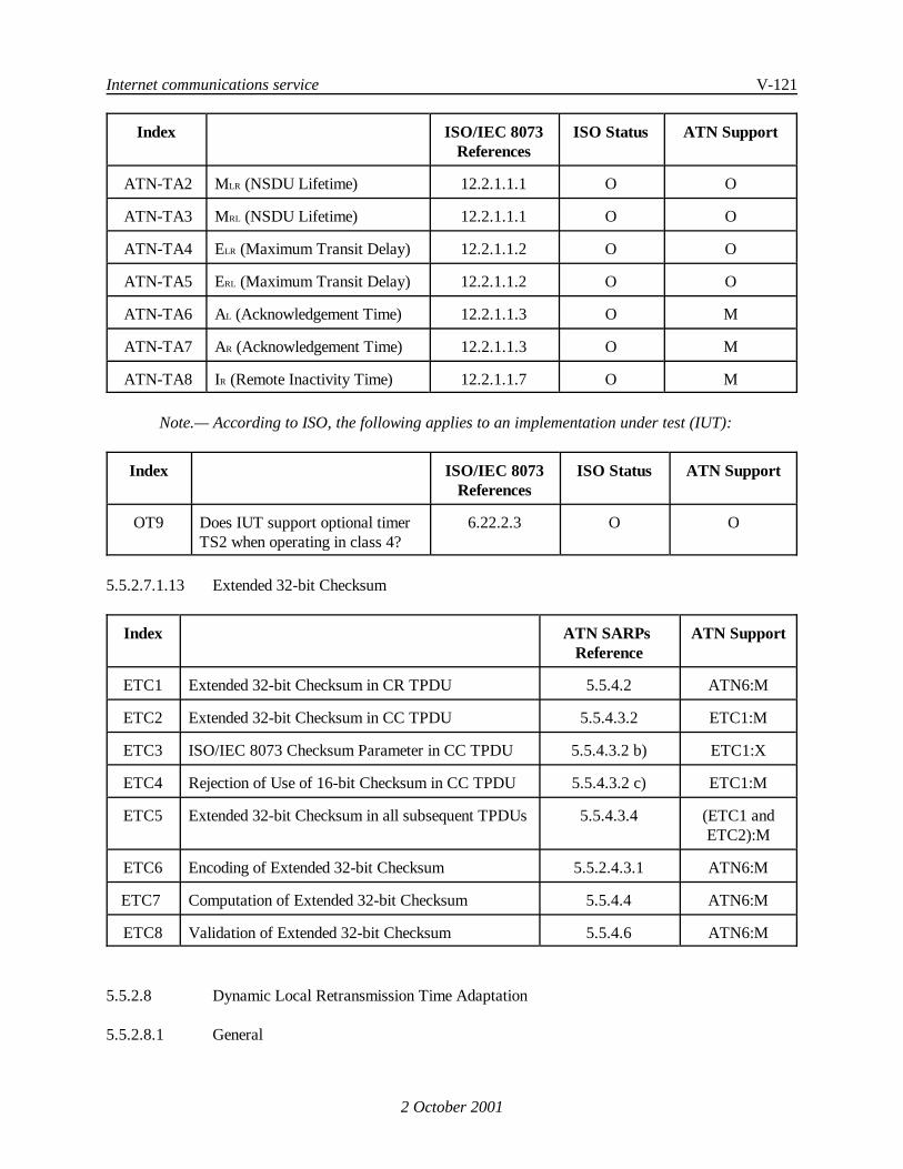
Internet communications service V-121
Index ISO/IEC 8073References
ISO Status ATN Support
2 October 2001
ATN-TA2 M LR (NSDU Lifetime) 12.2.1.1.1 O O
ATN-TA3 M RL (NSDU Lifetime) 12.2.1.1.1 O O
ATN-TA4 ELR (Maximum Transit Delay) 12.2.1.1.2 O O
ATN-TA5 ERL (Maximum Transit Delay) 12.2.1.1.2 O O
ATN-TA6 AL (Acknowledgement Time) 12.2.1.1.3 O M
ATN-TA7 AR (Acknowledgement Time) 12.2.1.1.3 O M
ATN-TA8 I R (Remote Inactivity Time) 12.2.1.1.7 O M
Note.— According to ISO, the following applies to an implementation under test (IUT):
Index ISO/IEC 8073References
ISO Status ATN Support
OT9 Does IUT support optional timerTS2 when operating in class 4?
6.22.2.3 O O
5.5.2.7.1.13 Extended 32-bit Checksum
Index ATN SARPsReference
ATN Support
ETC1 Extended 32-bit Checksum in CR TPDU 5.5.4.2 ATN6:M
ETC2 Extended 32-bit Checksum in CC TPDU 5.5.4.3.2 ETC1:M
ETC3 ISO/IEC 8073 Checksum Parameter in CC TPDU 5.5.4.3.2 b) ETC1:X
ETC4 Rejection of Use of 16-bit Checksum in CC TPDU 5.5.4.3.2 c) ETC1:M
ETC5 Extended 32-bit Checksum in all subsequent TPDUs 5.5.4.3.4 (ETC1 andETC2):M
ETC6 Encoding of Extended 32-bit Checksum 5.5.2.4.3.1 ATN6:M
ETC7 Computation of Extended 32-bit Checksum 5.5.4.4 ATN6:M
ETC8 Validation of Extended 32-bit Checksum 5.5.4.6 ATN6:M
5.5.2.8 Dynamic Local Retransmission Time Adaptation
5.5.2.8.1 General
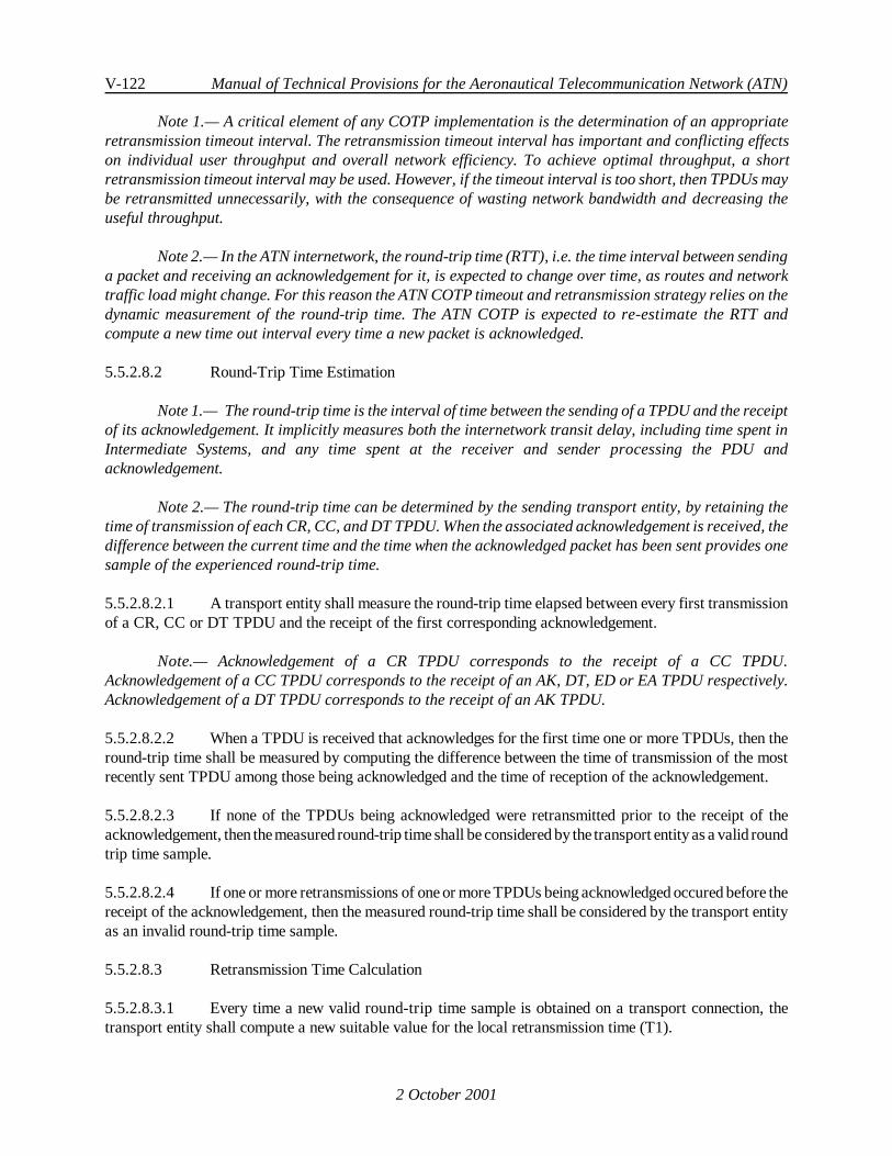
V-122 Manual of Technical Provisions for the Aeronautical Telecommunication Network (ATN)
2 October 2001
Note 1.— A critical element of any COTP implementation is the determination of an appropriateretransmission timeout interval. The retransmission timeout interval has important and conflicting effectson individual user throughput and overall network efficiency. To achieve optimal throughput, a shortretransmission timeout interval may be used. However, if the timeout interval is too short, then TPDUs maybe retransmitted unnecessarily, with the consequence of wasting network bandwidth and decreasing theuseful throughput.
Note 2.— In the ATN internetwork, the round-trip time (RTT), i.e. the time interval between sendinga packet and receiving an acknowledgement for it, is expected to change over time, as routes and networktraffic load might change. For this reason the ATN COTP timeout and retransmission strategy relies on thedynamic measurement of the round-trip time. The ATN COTP is expected to re-estimate the RTT andcompute a new time out interval every time a new packet is acknowledged.
5.5.2.8.2 Round-Trip Time Estimation
Note 1.— The round-trip time is the interval of time between the sending of a TPDU and the receiptof its acknowledgement. It implicitly measures both the internetwork transit delay, including time spent inIntermediate Systems, and any time spent at the receiver and sender processing the PDU andacknowledgement.
Note 2.— The round-trip time can be determined by the sending transport entity, by retaining thetime of transmission of each CR, CC, and DT TPDU. When the associated acknowledgement is received, thedifference between the current time and the time when the acknowledged packet has been sent provides onesample of the experienced round-trip time.
5.5.2.8.2.1 A transport entity shall measure the round-trip time elapsed between every first transmissionof a CR, CC or DT TPDU and the receipt of the first corresponding acknowledgement.
Note.— Acknowledgement of a CR TPDU corresponds to the receipt of a CC TPDU.Acknowledgement of a CC TPDU corresponds to the receipt of an AK, DT, ED or EA TPDU respectively.Acknowledgement of a DT TPDU corresponds to the receipt of an AK TPDU.
5.5.2.8.2.2 When a TPDU is received that acknowledges for the first time one or more TPDUs, then theround-trip time shall be measured by computing the difference between the time of transmission of the mostrecently sent TPDU among those being acknowledged and the time of reception of the acknowledgement.
5.5.2.8.2.3 If none of the TPDUs being acknowledged were retransmitted prior to the receipt of theacknowledgement, then themeasured round-trip time shall be considered by the transport entity as a valid roundtrip time sample.
5.5.2.8.2.4 If one or more retransmissions of one or more TPDUs being acknowledged occured before thereceipt of the acknowledgement, then the measured round-trip time shall be considered by the transport entityas an invalid round-trip time sample.
5.5.2.8.3 Retransmission Time Calculation
5.5.2.8.3.1 Every time a new valid round-trip time sample is obtained on a transport connection, thetransport entity shall compute a new suitable value for the local retransmission time (T1).

Internet communications service V-123
2 October 2001
5.5.2.8.3.2 Recommendation.— The initial value of the local retransmission time (T1init) should becomputed as a function of an initial round trip time estimate (SRTTinit) and of its mean deviation (Dinit), asfollows:
SRTTinit = S0
Dinit = SRTTinit/4T1init = SRTTinit + 4 * D init + AR
where:
a) S0 is the first valid round-trip time sample, and
b) AR is the Remote Acknowledgement Time value.
5.5.2.8.3.3 Recommendation.— Any further value of the local retransmission time (T1) should becomputed as a function of a "smoothed" round-trip time estimate (SRTT) and of its "smoothed" meandeviation D, as follows:
Err = S - SRTTprev
SRTTnew = SRTTprev + g * ErrDnew = Dprev+ h * ( ABS(Err) - Dprev )T1= SRTTnew + 4 * D new + AR
where:a) SRTTprev and SRTTneware the previous and new computed values of the "smoothed"
round trip time estimate. Initially, SRTTprev is set to SRTTinit.
b) Dprev and Dnew are the previous and new computed values of the "smoothed" meandeviation. Initially, Dprev is set to Dinit.
c) Err is the difference between the measured value just obtained (S) and the previousSRTTprev.
d) The gains g and h are constants that control how rapidly the smoothed round-triptime and its smoothed mean deviation adapt to change. g is set to 1/8. h is set to1/4.
e) ABS(Err) is the absolute value of Err.
f) T1 is the Local Retransmission Time value.
g) AR is the Remote Acknowledgement Time value.
Note 1.— This algorithm is derived from the Jacobson's algorithm and differs only by the additionof the Remote Acknowledgement Time (AR) in the formula used for the computation of the LocalRetransmission Time value. This change is in response to the unique requirements of the aeronauticalenvironment which may require long acknowledgement times.
Note 2.— The SRTT, D and T1 variables are maintained on a per transport connection basis.

V-124 Manual of Technical Provisions for the Aeronautical Telecommunication Network (ATN)
2 October 2001
5.5.2.8.3.4 If an alternative algorithm for the computation of the Local Retransmission Time (T1) isimplemented over air/ground connections, then its performance shall be at least equivalent to the performanceof the algorithm recommended above.
5.5.2.8.4 Retransmission Time Backoff Procedure
5.5.2.8.4.1 Whenever a retransmission timeout occurs, the transport entity shall double the LocalRetransmission Time value before retransmitting the unacknowledged data.
Note.— This procedure is known as exponential back-off. Back-off is performed independently of theround-trip time estimation, since without an acknowledgement there is no new timing information to be fedinto the Retransmission Time value calculation.
5.5.2.8.4.2 If as a result of this procedure the Local Retransmission Time exceeds its maximumvalue(see5.5.2.8.5), then the Local Retransmission Time shall be set to its maximum value.
5.5.2.8.4.3 Whenever an invalid round-trip time sample is obtained, the Retransmission Time value shallremain set to the value having resulted from the operation of the previous backoff procedure.
Note.— This rule is derived from a procedure known as the Karn's algorithm.
5.5.2.8.5 Initial, Minimum and Maximum Local Retransmission Time Value
5.5.2.8.5.1 The transport entity shall maintain the value of the Local Retransmission Time within abounded range.
5.5.2.8.5.2 The lower and upper bound of the Local Retransmission Time shall be configurable.
5.5.2.8.5.3 When intended for operation over Air/Ground subnetworks, the lower and upper bound of theLocal Retransmission Time shall be set to the minimum and maximum T1 values respectively specified inTable 5.5-1.
5.5.2.8.5.4 When intended for operation over Air/Ground subnetworks, the initial value of the LocalRetransmission Time shall be set to the nominal T1 value specified in Table 5.5-1.
5.5.2.8.5.5 When intended for operation exclusively over Ground/Ground subnetworks, the initial valueof the Local Retransmission Time shall be greater than the maximum expected round-trip time.

Internet communications service V-125
2 October 2001
5.5.3 Connectionless Mode Transport Protocol Operation
5.5.3.1 Connectionless Mode Transport Protocol Overview
5.5.3.1.1 ATN End Systems shall implement the ISO/IEC 8602 transport protocol in order to provideConnectionless Mode communications over the ATN Internet.
Note.— The ATN CLTS model conforms to the service model defined in ISO/IEC 8072.
5.5.3.1.2 The CLTP shall operate over the CLNS provided by the ATN Network Layer, according tothe provisions in 5.5.3.5.
5.5.3.2 Connectionless Mode Transport Service Primitives
Note 1.— For the purposes of describing the notional interfaces between different OSI protocollayers, each protocol layer is assumed to provide a service to the next higher protocol layer. The assumedservice provided by the ATN Transport Layer to its user is described in ISO/IEC 8072.
Note 2.— ISO/IEC 8072 limits CL user-data to a maximum of 63488 octets per TSDU.
Note 3.— There is no requirement to implement the service specified in ISO/IEC 8072 as a softwareinterface.
5.5.3.2.1 T-UNITDATA Request
5.5.3.2.1.1 The source and destination Transport Addresses shall conform to the ATN Transport LayerAddressing provisions as specified in 5.4.
5.5.3.2.2 T-UNITDATA Indication
Note.— All of the associated parameter values are equal to the values passed to the TS provider viathe T-UNITDATA Request primitive, except possibly the QoS parameter values.
5.5.3.3 ATN Connectionless Mode Transport Quality of Service Parameters
5.5.3.3.1 General
5.5.3.3.1.1 The Transport Layer shall support the use of checksums on a per TSDU (Transport ServiceData Unit) basis.
Note.— The actual use of this feature will be dependant upon the application*s requirements.
5.5.3.3.2 Priority
5.5.3.3.2.1 Thetransport entity providing theconnectionless mode transport service shall allow a TS-userto specify TSDU priority in the range [0-14].
Note.— The CLTP itself does not support a priority field in the TPDU.

V-126 Manual of Technical Provisions for the Aeronautical Telecommunication Network (ATN)
2 October 2001
5.5.3.3.3 Security
5.5.3.3.3.1 The transport entity providing theconnectionless modetransport serviceshall allow a TS-userto specify the ATN Security Label in the T-UNITDATA request.
Note.— The CLTP itself does not support a security parameter field in the TPDU.
5.5.3.3.4 Residual Error Rate
Note.— Three qualitative levels of RER are possible for use with the connectionless transportservice. These correspond to no checksums, use of the 16-bit checksum specified in ISO/IEC 8602, and theExtended 32-bit Checksum described in this specification.
5.5.3.3.4.1 The Transport Layer shall allow a TS-user to specify a Residual Error Rate as threequalitative levels, i.e. low, medium and high.
5.5.3.3.4.2 When supported, a low Residual Error Rate shall correspond to the use of the Extended 32-bitChecksum described in 5.5.4. Otherwise, a low residual error rate shall be equivalent to a medium ResidualError Rate.
5.5.3.3.4.3 A medium Residual Error Rate shall correspond to the use of the 16-bit TPDU checksumdescribed in ISO/IEC 8602.
5.5.3.3.4.4 A high Residual Error Rate shall correspond to non-use of any transport layer checksum.
5.5.3.4 Encoding of Transport Protocol Data Units
5.5.3.4.1 The encoding of TPDUs shall conform to ISO/IEC 8602 for the CLTP.
5.5.3.5 Use of the ATN Network Service
Note.— This section specifies how the CLTP operates over the CLNS provided by the ATN NetworkLayer.
5.5.3.5.1 Use of the N-UNITDATA Request
5.5.3.5.1.1 General
5.5.3.5.1.1.1 The Transport Layer shall use the N-UNITDATA Request Primitive, as defined in ISO/IEC8602, to transmit TPDUs.
5.5.3.5.1.2 NS-user-data
Note.— Transport Entities transmit TPDUs as NS-user-data of the N-UNITDATA Request primitive.
5.5.3.5.1.3 Network Service Access Point Addresses
Note.— The Transport Layer has knowledge of source and destination address parameters only asoctet strings.

Internet communications service V-127
2 October 2001
5.5.3.5.1.4 Network Quality of Service
5.5.3.5.1.4.1 General
5.5.3.5.1.4.1.1 The transport entity providing the connectionless mode transport service shall use the networkQoS parameters as defined in the sections below.
5.5.3.5.1.4.2 Network Layer Priority
5.5.3.5.1.4.2.1 Thetransport entity providing the connectionless mode transport service shall use the networkpriority parameter to indicate the relative priority of an NSDU. The NSDU priority shall be determined fromthe TSDU priority, using the mapping given in Table 1-2.
5.5.3.5.1.4.3 Network Layer Security
5.5.3.5.1.4.3.1 The transport entity providing the connectionless modetransport serviceshall use theSecurityLabel provided in the T-UNITDATA request as the value of the N-UNITDATA security parameter.
5.5.3.5.2 Use of the N-UNITDATA Indication
Note.— Following ISO/IEC 8602, the Transport Layer receives TPDUs from the NetworkLayer-provided N-UNITDATA Indication primitive.
5.5.3.5.2.1 Network Quality of Service
5.5.3.5.2.1.1 To meet the ISO/IEC 8072 service specification, the transport entity providing theconnectionless mode transport service shall translate the received NSDU priority to the TSDU priority usingthe mapping shown in Table 1-2.
5.5.3.6 ATN Connectionless Mode Transport APRL
Note.— The requirements for the CLTP are provided in the form of an APRL. The APRL has beenprepared using the PICS proforma provided with ISO/IEC 8602.
5.5.3.6.1 General
5.5.3.6.1.1 An implementation of the ISO/IEC 8602 Transport Protocol shall be used in an ATN EndSystem if and only if its PICS is in compliance with the APRL provided with these SARPs.
5.5.3.6.2 Protocol Implementation
Item Protocol Function Support ISO/IEC8602
Reference
ISOStatus
ATNSupport
NS Network service selection 5.3.2.2 M M
AM Address mapping 5.3.2.3 M M

V-128 Manual of Technical Provisions for the Aeronautical Telecommunication Network (ATN)
Item Protocol Function Support ISO/IEC8602
Reference
ISOStatus
ATNSupport
2 October 2001
PDU Support
UD1 Unitdata PDU supported on transmission 6.1.3 M M
UD2AM Unitdata PDU supported on reception 6.1.3 M M
Parameters of the Unitdata PDU onTransmission
TpTc <t> TPDU UD Checksum 6.2.4.1, ATNSARPs
Reference:5.5.4.4
O RER_Medium:M,
RER_High or(RER_Low
and ATN6):X
TpTs <t> TPDU UD Source Transport-Selector 6.2.4.1 M M
TpTd <t> TPDU UD Destination Transport-Selector
6.2.4.1 M M
TpTu <t> TPDU UD User Data 6.2.4.1 M M
TpTetc <t> TPDU UD Extended 32-bit Checksum ATN SARPsReference:5.5.4.4.1
-- (RER_Lowand ATN6):M
Parameters of the Unitdata PDU onReception
TpRc <r> TPDU UD Checksum 6.2.4.2 M M
TpRs <r> TPDU UD Source Transport-Selector 6.2.4.2 M M
TpRd <r> TPDU UD Destination Transport-Selector
6.2.4.2 M M
TpRu <r> TPDU UD User Data 6.2.4.2 M M
TpRetc <r> TPDU UD Extended 32-bit Checksum ATN SARPsReference:5.5.4.1.1
-- M
Service Support
CL Connectionless Mode Network Service 6.2 M M
RER_Low: if low RER requestedthen trueelsefalseRER_Medium: if medium RER requestedthen trueelsefalseRER_High: if high RER requestedthen trueelsefalse

Internet communications service V-129
2 October 2001
5.5.4 Extended 32-bit Checksum5.5.4.1 General
5.5.4.1.1 When present in a TPDU, the Extended 32-bit Checksum parameter shall be validated usingthe algorithm specified in 5.5.4.6.
5.5.4.1.2 If the validation fails, the TPDU shall be discarded without further processing.
5.5.4.2 Negotiating the Use of Extended 32-bit Checksum in Transport Connections
5.5.4.2.1 When Extended 32-bit Checksums are supported and a low Residual Error Rate is requested,the CR TPDU shall contain both an Extended 32-bit Checksum parameter computed as specified in 5.5.4.4and the ISO/IEC 8073 checksum parameter. The option for the “Non-use of checksum” shall not be proposedin the “Additional Option Selection” parameter of the CR TPDU.
Note.— Including the Extended 32-bit Checksum parameter in a CR TPDU implies that use ofExtended 32-bit Checksum is proposed.
5.5.4.2.2 The Extended 32-bit Checksum parameter value shall be calculated first and the resultingcheck digits inserted into the TPDU before the ISO/IEC 8073 checksum is calculated.
5.5.4.2.3 The value of the ISO/IEC 8073 checksum parameter shall be set to zero before the Extended32-bit Checksum is computed.
5.5.4.2.4 When a medium Residual Error Rate is requested, the CR TPDU shall contain the ISO/IEC8073 checksum parameter; the Extended 32-bit Checksum parameter shall not be present. The option for the“Non-useof checksum” shall not be proposed in the "Additional Option Selection" parameter of theCR TPDU.
5.5.4.2.5 When a high Residual Error Rate is requested, the Extended 32-bit Checksum parameter shallnot be present. The option for the “Non-use of checksum” shall be proposed in the "Additional OptionSelection" parameter of the CR TPDU.
5.5.4.3 Accepting the Use of Checksums
5.5.4.3.1 A CR TPDU that does not contain an Extended 32-bit Checksum parameter shall beprocessedin compliance with ISO/IEC 8073.
5.5.4.3.2 When a CR TPDU is received that includes the Extended 32-bit Checksum parameter, thenthe connection responder shall validate the received checksum as specified in 5.5.4.6 and, in order to signalacceptance of Extended 32-bit Checksum:
a) Compute and include an Extended 32-bit Checksum parameter, as specified in5.5.4.4, in the responding CC TPDU;
b) Omit the ISO/IEC 8073 checksum parameter from the responding CC TPDU;
c) Confirm the use of a checksum mechanism by setting the option bit for the “Non-useof checksum” to zero in the "Additional Option Selection" parameter of theresponding CC TPDU.

V-130 Manual of Technical Provisions for the Aeronautical Telecommunication Network (ATN)
2 October 2001
Note.— This specification extends the semantic of the ISO/IEC8073 option for the “Non-use ofchecksum” to mean “Non-use of any checksum mechanism”. Setting this option to “No” means that the useof one of the checksum mechanisms is proposed or accepted respectively. Which checksum mechanism isproposed or accepted is determined by the presence or absence of the Extended 32-bit Checksum parameterwithin the CR or CC TPDU respevctively.
5.5.4.3.3 TheISO/IEC 8073 checksumshall beverified as correct before theExtended 32-bit Checksumis verified.
5.5.4.3.4 Once the use of Extended 32-bit Checksums is accepted, all other TPDUs exchanged on thesame transport connection, in either direction, shall also include the Extended 32-bit Checksum parametercomputed as specified in 5.5.4.4, and shall not include the ISO/IEC 8073 checksum parameter. Any TPDUreceived without the Extended 32-bit Checksum parameter or which includes an ISO/IEC 8073 checksumparameter shall be discarded.
5.5.4.3.5 If a TPDU other than a CR TPDU includes both an Extended 32-bit Checksum parameter andan ISO/IEC 8073 checksum parameter shall be considered as a protocol error.
5.5.4.3.6 When the use of the Extended 32-bit Checksum is not acceptable, then the Extended 32-bitChecksum parameter shall not be included in the CC TPDU. Use of the ISO/IEC 8073 16-bit checksum shallbe accepted if proposed.
Note 1.— There is no difference between rejecting the use of the Extended 32-bit Checksum and theresponse of an implementation that does not support Extended 32-bit Checksums.
Note 2.— It is generally expected that if the Extended 32-bit Checksum is proposed, then its use isnecessary and it will be accepted. Rejection is very much an exceptional situation.
5.5.4.3.7 The Extended 32-bit Checksum parameter shall not be included in any subsequent TPDUsexchanged on the same transport connection if an Extended 32-bit Checksum parameter is not present in theCC TPDU.
5.5.4.4 Use in Connectionless Mode
5.5.4.4.1 When supported and when a low Residual Error Rate is requested by the service user, theExtended 32-bit Checksum shall be computed as specified in 5.5.4.4 and included in the UD TPDU Headeras the value of the Extended 32-bit checksum parameter. The ISO/IEC 8602 Checksum parameter shall notbe present.
Note.— The sender needs to know a priori that the intended recipient supports the Extended 32-bitchecksum; otherwise the UD TPDU will be discarded on receipt due to it containing an unrecognisedparameter.
5.5.4.4.2 When a medium Residual Error Rate is requested by the service user, then the ISO/IEC 8602Checksum shall be computed and included in the UD TPDU Header.
5.5.4.4.3 When a high Residual Error Rate is requested by the service user, then neither the Extended32-bit Checksum parameter nor the ISO/IEC 8602 Checksum parameter shall be present.

Internet communications service V-131
2 October 2001
5.5.4.5 Extended 32-bit Checksum Computation
Note 1.— The style of Appendix B of ISO/IEC 8073 is followed in the definition of the Extended 32-bit Checksum algorithm.
Note 2.— This algorithm has been derived from: Fletcher, J. G., "An Arithmetic Checksum for SerialTransmissions", IEEE Transactions on Communications, Vol. COM-30, No. 1, January 1982, pp. 247-252.
5.5.4.5.1 Symbols
Note.— The following symbols are used:
a) C0, C1, C2, C3 are variables used by the algorithm;
b) i is the number (i.e. position) of an octet within the TPDU;
c) n is the number (i.e. position) of the first octet of the Extended 32-bit Checksumparameter;
d) L is the length of the complete TPDU including the "pseudo trailer"; and
e) Xj is the value of the jth octet of the Extended 32-bit Checksum parameter (intransmission order).
5.5.4.5.2 Arithmetic Conventions
5.5.4.5.2.1 Addition shall be performed in one of the two following modes:
a) modulo 255; or
b) ones complement arithmetic in which if any of the variables has the value minus zero(i.e. 0xFFFF) shall be regarded as though it were plus zero (i.e. 0).
5.5.4.5.3 Algorithm for Generating the Checksum Parameter
5.5.4.5.3.1 The complete TPDU with the Extended 32-bit Checksum Parameter value field set to zeroshall be set up.
5.5.4.5.3.2 A "pseudo trailer" created from:
a) the length of the destination NSAP Address;
b) the destination NSAP Address;
c) the length of the source NSAP Address; and
d) the source NSAP Address
and encoded identically to their encoding in the CLNP header, shall be appended to the TPDU.

V-132 Manual of Technical Provisions for the Aeronautical Telecommunication Network (ATN)
2 October 2001
Note 1.— This pseudo trailer is not part of the TPDU and is never transmitted to the destination endsystem.
Note 2.— A pseudo trailer rather than a pseudo header is used because the check digits have to bemoved to the end of the TPDU by the receiver and hence a trailer will have to be constructed anyway.
5.5.4.5.3.3 The Extended 32-bit Checksum shall be created by the following algorithm:
1) Initialise C0 , C1, C2 and C3 to zero;
2) Process each octet in the combined TPDU and pseudo trailer sequentially from i = 1to L by
a) adding the value of the octet to C0; then
b) adding the value of C0 to C1, C1 to C2, and C2 to C3;
3) Set the octets of the Extended 32-bit Checksum parameter as follows:
a) X0 = - ( C0 + C1 + C2 + C3 );
b) X1 = C1 + 2 * C2 + 3 * C3;
c) X2 = - ( C2 + 3 * C3 ); and
d) X3 = C3;
4) Discard the pseudo trailer octets.
5.5.4.6 Algorithm for Checking the Checksum Parameter
5.5.4.6.1 The transport entity shall appended to the received TPDU a "pseudo trailer" which is createdfrom the source and destination NSAP Addresses associated with the incoming TPDU and the value of thereceived Extended 32-bit Checksum parameter in the following order:
a) the length of the destination NSAP Address;
b) the destination NSAP Address;
c) the length of the source NSAP Address;
d) the source NSAP Address;
encoded identically to their encoding in the CLNP Header
e) the octets of the Extended 32-bit Checksum parameter in the same order in whichthey appear in the checksum parameter.
5.5.4.6.2 The value of the Extended 32-bit Checksum Parameter shall be set to zero.

Internet communications service V-133
2 October 2001
5.5.4.6.3 If the received TPDU is a CR TPDU, then the value of the 16-bit checksum parameter shallbe set to zero.
5.5.4.6.4 The Extended 32-bit Checksum shall be validated as follows:
1) Initialise C0, C1, C2 and C3 to zero;
2) Process each octet in the combined TPDU and pseudo trailer sequentially from i = 1to L by
a) adding the value of the octet to C0; then
b) adding the value of C0 to C1, C1 to C2, and C2 to C3;
3) Discard the pseudo trailer;
4) If, when all the octets have been processed, one or more of the variables C0, C1, C2or C3 do not have the value zero, then the checksum validation has failed.

V-134 Manual of Technical Provisions for the Aeronautical Telecommunication Network (ATN)
2 October 2001
5.6 INTERNETWORK SERVICE AND PROTOCOL SPECIFICATION
5.6.1 Introduction
Note 1.— The ATN Internet comprises a number of interconnected ATN routers and constituentsubnetworks supporting data communication among host computers operating the ATN Internet protocols.
Note 2.— All ATN NPDUs (Network Protocol Data Units) are encapsulated within appropriatesubnetwork protocol data units for transfer among ATN network entities using the connectionless ISO OSINetwork Layer service provided by the ATN Internet. As the ATN Internet protocol is connectionless, anyinformation required to process a particular NPDU is carried within the header of that network protocoldata unit for processing by ATN routers and host computers.
5.6.1.1 Scope
Note 1.— This chapter provides requirements and recommendations pertaining to the use of theISO/IEC 8473 by ATN End System and Intermediate System Network entities. This Chapter is concerned withthe use of ISO/IEC 8473 in the context of the internetworking protocol approach to the provision of CLNSas defined in ISO/IEC 8348. This Chapter contains ATN-specific protocol implementations and is concernedwith the interoperability of protocol implementations. It therefore provides appropriate compliancestatements and APRLs for this purpose.
Note 2.— The ATN Network Layer Connectionless-Mode Network Service supports the transfer ofa connectionless network service data unit (NSDU) from a source NSAP to a destination NSAP within theATN network. Each such NSDU transfer is the result of a single invocation of the connectionless-modeNetwork Service encompassed within the ATN.
5.6.1.2 Applicability of Requirements
5.6.1.2.1 All ATN Intermediate System and End System Network entities shall comply with theprovisions contained in 5.6.2 and 5.6.3, in addition to all APRLs specified in 5.6.4.

Internet communications service V-135
2 October 2001
5.6.2 ATN Specific Features
5.6.2.1 Purpose of ATN Specific Features
Note 1.— The ATN infrastructure, referred to as an Internet, comprises the interconnection ofcomputers with gateways and routers via real subnetworks. This internetworking infrastructure, allows forthe incorporation of differing Air/Ground and Ground/Ground subnetworks servicing differing user groups,i.e., Air Traffic Services (ATS), Aeronautical Operational Control Services (AOC), and others.
Note 2.— The CLNP (Connectionless Network Protocol) protocol used to operate thisinternetworking infrastructure is based on ISO/IEC 8473 with ATN-specific additions to reflect the uniquecommunications environment of the ATN.
Note 3.— The ATN specific functions listed in this chapter reflect responses to theadditionalfunctional needs of ATN Network entities in order to support user requirements concerned with:
a) Ensuring that information is conveyed about Traffic Type and Routing Policyrequirements pertaining to user data in NPDUs;
b) Ensuring that a priority scheme can be applied for management of End Systems andIntermediate Systems output queues and buffers;
c) Ensuring that specific policies and procedures are available to handle congestionavoidance and congestion control requirements within the ATN.
5.6.2.2 The Security Function
5.6.2.2.1 General
5.6.2.2.1.1 The SECURITY Function of ISO/IEC 8473, as defined in this specification, shall besupported by ATN End System or Intermediate System Network entities receiving or transmitting inter-domaintraffic other than Traffic Type as General Communications.
5.6.2.2.1.2 ATN Network entities shall therefore provide the Globally Unique Security format for allcreated NPDUs.
5.6.2.2.1.3 The sole exception to this requirement is for General Communications traffic where noSecurity parameter information is required to be encoded in created NPDUs.
5.6.2.2.2 Encoding of the Security Parameter
5.6.2.2.2.1 The CLNP Options Security Parameter shall be used in the ATN to convey information aboutthe Traffic Type and Routing Policy Requirements pertaining to the user data of the NPDU (other than GeneralCommunications).
Note.— The CLNP Options Security Parameter may also be used to convey a security classification.
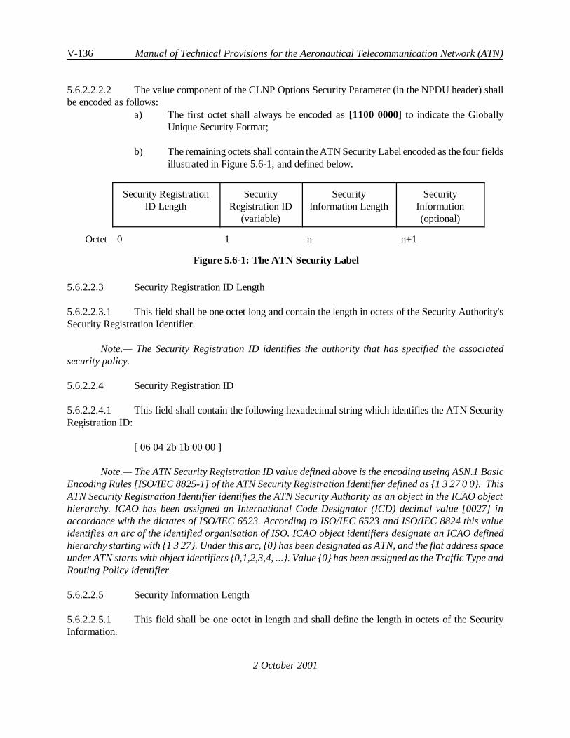
V-136 Manual of Technical Provisions for the Aeronautical Telecommunication Network (ATN)
2 October 2001
5.6.2.2.2.2 The value component of the CLNP Options Security Parameter (in the NPDU header) shallbe encoded as follows:
a) The first octet shall always be encoded as[1100 0000] to indicate the GloballyUnique Security Format;
b) The remaining octets shall contain the ATN Security Label encoded as the four fieldsillustrated in Figure 5.6-1, and defined below.
Security RegistrationID Length
SecurityRegistration ID
(variable)
SecurityInformation Length
SecurityInformation(optional)
Octet 0 1 n n+1
Figure 5.6-1: The ATN Security Label
5.6.2.2.3 Security Registration ID Length
5.6.2.2.3.1 This field shall be one octet long and contain the length in octets of the Security Authority'sSecurity Registration Identifier.
Note.— The Security Registration ID identifies the authority that has specified the associatedsecurity policy.
5.6.2.2.4 Security Registration ID
5.6.2.2.4.1 This field shall contain the following hexadecimal string which identifies the ATN SecurityRegistration ID:
[ 06 04 2b 1b 00 00 ]
Note.— The ATN Security Registration ID value defined above is the encoding useing ASN.1 BasicEncoding Rules [ISO/IEC 8825-1] of the ATN Security Registration Identifier defined as {1 3 27 0 0}. ThisATN Security Registration Identifier identifies the ATN Security Authority as an object in the ICAO objecthierarchy. ICAO has been assigned an International Code Designator (ICD) decimal value [0027] inaccordance with the dictates of ISO/IEC 6523. According to ISO/IEC 6523 and ISO/IEC 8824 this valueidentifies an arc of the identified organisation of ISO. ICAO object identifiers designate an ICAO definedhierarchy starting with {1 3 27}. Under this arc, {0} has been designated as ATN, and the flat address spaceunder ATN starts with object identifiers {0,1,2,3,4,...}. Value {0} has been assigned as the Traffic Type andRouting Policy identifier.
5.6.2.2.5 Security Information Length
5.6.2.2.5.1 This field shall be one octet in length and shall define the length in octets of the SecurityInformation.

Internet communications service V-137
2 October 2001
5.6.2.2.5.2 If there is no security information, this field shall be set to zero.
5.6.2.2.6 Security Information
5.6.2.2.6.1 General
5.6.2.2.6.1.1 When present, the Security Information field of the ATN Security Label shall be used toconvey, as separate Tag Sets:
a) The Traffic Type and Routing Policy Requirements, if any, applicable to the transferof the user data through the ATN.
b) The Security Classification
5.6.2.2.6.1.2 When no traffic type is identified then the General Communications traffic type shall beassumed, with a routing policy requirement of “no preference”. When no security classification is specified then“unclassified” shall be assumed.
5.6.2.2.6.2 Encoding of the Security Information Field
5.6.2.2.6.2.1 TheSecurity Information Field shall comprisezero, oneor more Security Tag Sets. A SecurityTag with the same Tag Set Name shall not occur more than once in the options Security Parameter of theCLNP NPDU.
Tag Set Name Length Tag Set Name Tag Set Length Security Tag
Octet 0 1 n n+1
Figure 5.6-2: Security Tag Set Format
5.6.2.2.6.2.2 Each Security Tag Set shall consist of four fields, as illustrated in Figure 5.6-2, and shall beas defined in the following sections.
Note.— This format has been chosen to provide for an extensible type-length-value encoding methodfor security related information placed in the CLNP Header under rules specified by the ATN SecurityAuthority.
5.6.2.2.6.3 Security Tag Set Name Length
5.6.2.2.6.3.1 The Security Tag Set Name Length shall contain the length in octets of the Tag Set Namefield.
5.6.2.2.6.4 Security Tag Set Name
5.6.2.2.6.4.1 The Security Tag Set Name shall be used to uniquely identify the Tag Set.

V-138 Manual of Technical Provisions for the Aeronautical Telecommunication Network (ATN)
2 October 2001
5.6.2.2.6.5 Tag Set Length
5.6.2.2.6.5.1 The Tag Set Length Field shall contain the length in octets of the Security Tag field.
5.6.2.2.6.6 Security Tag
5.6.2.2.6.6.1 The Security Tag field shall be used to convey security related information for which thesyntax and semantics are identified by the preceding Tag Set Name.
5.6.2.2.6.7 Encoding of the Tag Set for Traffic Type and Associated Routing Policies
5.6.2.2.6.7.1 The Tag Set Name shall be set to [0000 1111].
5.6.2.2.6.7.2 When present in the CLNP options Security Parameter, this Tag Set shall always be the firstTag Set to be encoded in the Security Information field of the ATN Security Label.
Note.— This Tag Set is used to identify the traffic type of the data, whether it is for ATC or Airlinecommunications, and, for Operational Communications, any Routing Policy requirements that apply.
5.6.2.2.6.7.3 The Security Tag shall indicate the Routing Policy Requirements for the data contained in thesame NPDU, according to Table 5.6-1.
Note.— See 5.2.7 for detailed information on the ATN Security Policy.
Table 5.6-1 Encoding of Traffic Type Security Tag
Traffic Type Category SecurityTag Value
Semantics
ATN OperationalCommunications
Air Traffic ServiceCommunications(ATSC)
000 00001 No Traffic Type Policy Preference.
000 10000 Traffic preference for Class A ATSC route(s).
000 10001 Traffic preference for Class B ATSC route(s).
000 10010 Traffic preference for Class C ATSC route(s).
000 10011 Traffic preference for Class D ATSC route(s).
000 10100 Traffic preference for Class E ATSC route(s).
000 10101 Traffic preference for Class F ATSC route(s).
000 10110 Traffic preference for Class G ATSC route(s).
000 10111 Traffic preference for Class H ATSC route(s).
AeronauticalOperationalControl (AOC)
001 00001 No Traffic Type Policy Preference.
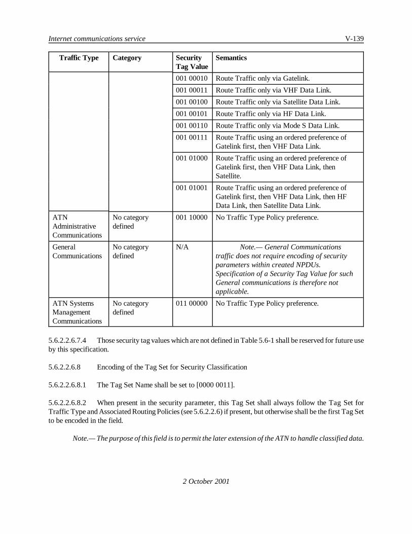
Internet communications service V-139
Traffic Type Category SecurityTag Value
Semantics
2 October 2001
001 00010 Route Traffic only via Gatelink.
001 00011 Route Traffic only via VHF Data Link.
001 00100 Route Traffic only via Satellite Data Link.
001 00101 Route Traffic only via HF Data Link.
001 00110 Route Traffic only via Mode S Data Link.
001 00111 Route Traffic using an ordered preference ofGatelink first, then VHF Data Link.
001 01000 Route Traffic using an ordered preference ofGatelink first, then VHF Data Link, thenSatellite.
001 01001 Route Traffic using an ordered preference ofGatelink first, then VHF Data Link, then HFData Link, then Satellite Data Link.
ATNAdministrativeCommunications
No categorydefined
001 10000 No Traffic Type Policy preference.
GeneralCommunications
No categorydefined
N/A Note.— General Communicationstraffic does not require encoding of securityparameters within created NPDUs.Specification of a Security Tag Value for suchGeneral communications is therefore notapplicable.
ATN SystemsManagementCommunications
No categorydefined
011 00000 No Traffic Type Policy preference.
5.6.2.2.6.7.4 Those security tag values which are not defined in Table 5.6-1 shall be reserved for future useby this specification.
5.6.2.2.6.8 Encoding of the Tag Set for Security Classification
5.6.2.2.6.8.1 The Tag Set Name shall be set to [0000 0011].
5.6.2.2.6.8.2 When present in the security parameter, this Tag Set shall always follow the Tag Set forTraffic Type and Associated Routing Policies (see 5.6.2.2.6) if present, but otherwise shall be the first Tag Setto be encoded in the field.
Note.— The purpose of this field is to permit the later extension of the ATN to handle classified data.

V-140 Manual of Technical Provisions for the Aeronautical Telecommunication Network (ATN)
2 October 2001
5.6.2.2.6.8.3 The Security Tag shall indicate the security classification of the NPDU according to thefollowing table:
Table 5.6-2 Encoding of the Security Classification Tag
Value SecurityClassification
0000 0001 unclassified
0000 0010 restricted
0000 0011 confidential
0000 0100 secret
0000 0101 top secret
0000 0110 to1111 1111
unassigned
5.6.2.2.6.8.4 Thosesecurity classification tag values which arenot assigned in Table5.6-2 shall bereservedfor future use by this specification.
5.6.2.3 Management of Network Priority
Note.— Network priority handling provisions are specified in 5.2.8.
5.6.2.4 Congestion Management
Note 1.— The congestion management provisions in the Network Layer are intended to guaranteethe notification to the Transport Layer of potential risks of congestion via the CE bit conveyed in the QoSMaintenance parameter of an ISO/IEC 8473 NPDU. 5.5.2.5 defines the measures that the Transport Layerimplements upon receipt of NPDUs with the CE bit set.
Note 2.— The above requirement is applicable to all types of ISO/IEC 8473 NPDUs.
5.6.2.4.1 Setting of the congestion experienced flag
5.6.2.4.1.1 The congestion experienced flag (CE-flag) in the QoS maintenance parameter in the optionspart of an NPDU header shall initially be set to zero by the originator of the NPDU.
5.6.2.4.1.2 When a NPDU is being forwarded by an ATN Intermediate System, the Intermediate Systemshall examine the depth of the output queue selected for that NPDU.
5.6.2.4.1.3 If the depth of the selected output queue exceeds a thresholdα (see Table 5.6-3), the ATNIntermediate System shall set the CE-flag in the NPDU header.

Internet communications service V-141
2 October 2001
Note.— The above assumes a single output queue per network (CLNP) priority. If mixed priorityqueues are implemented, which is valid provided that priority order is always maintained, then the CE-flagis set only when the number of NPDUs on the queue of the same or a higher priority exceeds alpha.
5.6.2.4.1.4 Once the CE-flag is set, it shall not be reset by any ATN Intermediate System traversed bythe NPDU further along to the path towards the destination.
5.6.2.4.2 Forwarding congestion information to the receiving NS-User
5.6.2.4.2.1 For each sequenceof NPDUs that together form an NSDU, thedestination network entity shallkeep two counters:
a) the first one, n-total, shall reflect the length of that sequence.
b) the second one, n-CE, shall reflect the number of those NPDUs of this sequence, thathad the CE-flag set on reception by the destination network entity.
Note.— Each NSDU is forwarded through the network as a sequence consisting of one or moreNPDUs.
5.6.2.4.2.2 When thedestination network entity passes an NSDU to the receiving NS-User, it shall conveythe associated counters n-total and n-CE to the NS-User.
Note.— The conveyance of the congestion information associated with an NSDU to the NS-User isa local matter.
5.6.2.4.3 Required algorithm values
5.6.2.4.3.1 The value settings defined in the following table shall be implemented:
Table 5.6-3 Required Value forα
Name Description Required range
α Output queue threshold 1 packet

V-142 Manual of Technical Provisions for the Aeronautical Telecommunication Network (ATN)
2 October 2001
5.6.3 ATN Specific Requirements for ISO/IEC 8473
Note.— This section defines ATN specific requirements on the ISO/IEC 8473 Protocol.
5.6.3.1 Segmentation Function
5.6.3.1.1 ATN Intermediate Systems (ISs) shall support both the segmenting and thenon-segmentingsubsets of ISO/IEC 8473.
5.6.3.1.2 ATN End Systems shall support the ISO/IEC 8473 segmenting subset.
Note.— Use of the non-segmenting subset of ISO/IEC 8473 for NPDUs whose packet size exceedsthe maximum SNSDU size supported by an underlying subnetwork will result in the packet being discarded.Use of the non-segmenting ISO/IEC 8473 subset is most appropriate for situations where the SNSDU sizeof the subnetwork(s) used for NPDU transfer is well understood.
5.6.3.2 Security Function
Note.— The ATN Specific use of the ISO/IEC 8473 Security Function is specified in 5.6.2.2.
5.6.3.3 Echo Request Function
5.6.3.3.1 Recommendation.— ATN End System and Intermediate System Network Entities (NEs)should support the ECHO REQUEST Function as invoked by Network Layer management.
Note.— The Echo Request Function is invoked to obtain information on the reachability of specificnetwork entities and the path characteristics between NEs through the operation of Network Layer routingfunctions.
5.6.3.4 Echo Response Function
5.6.3.4.1 ATN End Systems and Intermediate Systems shall support the Echo Response Function ofISO/IEC 8473.
Note.— The Echo Response function is performed by a Network Entity when it has received an EchoRequest (ERQ) PDU that has reached its destination. When invoked, the Echo Response function causes anEcho Response (ERP) PDU to be created.
5.6.3.4.2 If the data part of the received ERQ PDU contains an ERP PDU header, then the options partof the ERP PDU to be sent shall be identical to (copied from) the options part of the ERP PDU headercontained in the data part of the received ERQ PDU.
5.6.3.4.3 If the data part of the received ERQ PDU does not contain an ERP PDU header, then thesecurity, priority, and QoS maintenanceoptions of theERP PDU shall be identical to the corresponding optionsin the header of the ERQ PDU, if present.

Internet communications service V-143
2 October 2001
5.6.3.4.4 If the data part of the received ERQ PDU does not contain an ERP PDU header, and if thesecurity option (respectively the priority or QoS maintenance option) is not present in the received ERQ PDUheader, then the security option (respectively the priority or QoS maintenance option) shall not be included inthe ERP PDU.
5.6.3.4.5 If the data part of the received ERQ PDU does not contain an ERP PDU header, and if thepartial recording of route option is present in the received ERQ PDU header, then the partial recording of routeoption shall be specified in the ERP PDU, with the second octet of the parameter value field set to the value3.
5.6.3.5 Network Priority
Note.— The ATN Specific use of the ISO/IEC 8473 Priority is specified in 5.2.8.4.

V-144 Manual of Technical Provisions for the Aeronautical Telecommunication Network (ATN)
2 October 2001
5.6.4 APRLs
5.6.4.1 General
5.6.4.1.1 An implementation of the ISO/IEC 8473 Protocol shall be used in an ATN System if and onlyif its PICS is in compliance with the APRL provided in these SARPs.
Note.— The CLNP requirements list is a statement of which capabilities and options of the protocolat minimum are required to be implemented for the ATN environment. The requirements list may be used bythe protocol implementor as a check list to conform to this standard; by the supplier and procurer to providea detailed indication of the capabilities of an implementation; by the user to check the possibility ofinterworking between two different implementations; and by the protocol tester, as the basis for selectingappropriate tests against which to assess the claim for conformance to the protocol.
5.6.4.2 Support of ATN-Specific Network Layer features
Index Item ATN SARPsReference
ATN Support
ATN CLNP1 Encoding and use of the SecurityParameter
5.6.2.2 M
ATN CLNP2 Management of Network Priority 5.6.2.3, 5.2.8.4 M
ATN CLNP4 Echo Request Function 5.6.3.3 O
ATN CLNP5 Congestion Management 5.6.2.4 M
ATN CLNP6 Echo Response Function 5.6.3.4.1 M
ATN CLNP7 Echo Response parameter setting 5.6.3.4.2, 5.6.3.4.3,5.6.3.4.4
M

Internet communications service V-145
2 October 2001
5.6.4.3 Major Capabilities
Item Capability ISO/IEC 8473Reference
Status ATNSupport
ES End System O.1 O.1
IS Intermediate System O.1 O.1
FL-r <r> Full protocol 8473-1: 6 M M
FL-s <s> Full protocol 8473-1: 6 M M
NSS-r <r> Non-segmenting subset 8473-1: 5.2 M M
NSS-s <s> Non segmenting subset 8473-1: 5.2 IS:M^IS:O
IS:M^IS:O
IAS-r <r> Inactive subset 8473-1: 5.2 ES:O ES:O
IAS-s <s> Inactive subset 8473-1: 5.2IAS-r:M
^IAS-r:XIAS-r:M
^IAS-r:X
S802 SNDCF for ISO/IEC 8802 8473-2: 5.4 O.2 O
SCLL SNDCF for CL Link Service 8473-4: 5.3.1 O.2 O
SCOL SNDCF for CO Link Service 8473-4: 5.3.2 O.2 O
SX25 SNDCF for ISO/IEC 8208 8473-3: 5.4 O.2 O
ATN SNDCF SNDCF for MobileSubnetworks
ATN SARPsRef: 5.7
N/A ISMOB:MISGRD:O^IS:O
ISMOB: If ISO/IEC 8473 is used over Mobile Subnetworks, then ISMOB is true, else ISMOB is false.
ISGRD: If ISO/IEC 8473 is used over Ground Subnetworks, then ISGRD is true, else ISGRD is false.
O.1: The supported functions, NPDUs, associated parameters and timers required for End Systems areprovided in APRLs 5.6.4.4 through 5.6.4.11. The supported functions, NPDUs, associated parameters andtimers required for Intermediate Systems are provided in APRLs 5.6.4.12 through 5.6.4.18.
O.2: APRLs for the SNDCF for use with ISO/IEC 8802-2 subnetworks are provided in 5.7.7.2 and 5.7.7.3.APRLs for the SNDCF for use with ISO/IEC 8208 subnetworks are provided in 5.7.7.4 through 5.7.7.7.
5.6.4.4 End Systems - Supported Functions

V-146 Manual of Technical Provisions for the Aeronautical Telecommunication Network (ATN)
2 October 2001
Item Function ISO/IEC 8473-1Reference
Status ATNSupport
ePDUC PDU Composition 6.1 M M
ePDUD PDU Decomposition 6.2 M M
eHFA Header Format Analysis 6.3 M M
ePDUL-s <s> PDU Lifetime Control 6.4 M M
ePDUL-r <r> PDU Lifetime Control 6.4 O M
eRout Route PDU 6.5 M M
eForw Forward PDU 6.6 M M
eSegm Segment PDU 6.7 M M
eReas Reassemble PDU 6.8 M M
eDisc Discard PDU 6.9 M M
eErep Error Reporting 6.10 M M
eEdec-s <s> Header Error Detection 6.11 M M
eEdec-r <r> Header Error Detection 6.11 M M
eSecu-s <s> Security 6.13,ATN SARPsRef: 5.6.2.2
O M
eSecu-r <r> Security 6.13, ATNSARPs Ref.5.6.2.2
O M
eCRR-s <s> Complete Route Recording 6.15 O OX
eCRR-r <r> Complete Route Recording 6.15 O O
ePRR-s <s> Partial Route Recording 6.15 O M
ePRR-r <r> Partial Route Recording 6.15 O M
eCSR Complete Source Routing 6.14 O OX
ePSR Partial Source Routing 6.14 O OX
ePri-s <s> Priority 6.17, ATNSARPs Ref.5.6.3.5
O M

Internet communications service V-147
Item Function ISO/IEC 8473-1Reference
Status ATNSupport
2 October 2001
ePri-r <r> Priority 6.17, ATNSARPs Ref.5.6.3.5
O M
eQOSM-s <s> QOS Maintenance 6.16 O M
eQOSM-r <r> QOS Maintenance 6.16 O M
eCong-s <s> Congestion Notification 6.18 eQOSM-s:M
eQOSM-s:M
eCong-r <r> Congestion Notification 6.18 O M
ePadd-s <s> Padding 6.12 O OX
ePadd-r <r> Padding 6.12 M M
eEreq Echo request 6.19, ATNSARPs Ref.5.6.3.3
O O
eErsp Echo response 6.20, ATNSARPs Ref.5.6.3.4
O M
eSegS Create segments smaller thannecessary
6.8 O O

V-148 Manual of Technical Provisions for the Aeronautical Telecommunication Network (ATN)
2 October 2001
5.6.4.5 End Systems - Supported NPDUs
Item NPDU ISO/IEC8473-1Reference
Status ATN Support
eDT-t DT (full protocol) transmit 7.7 M M
eDT-r DT (full protocol) receive 7.7 M M
eDTNS-t DT (non-segment) transmit 7.7 NSS-s:M NSS-s:M
eDTNS-r DT (non-segment) receive 7.7 M M
eER-t ER transmit 7.9 M M
eER-r ER receive 7.9 M M
eIN-t Inactive PDU transmit 7.8 IAS-s:M IAS-s:M
eIN-r Inactive PDU receive 7.8 IAS-r:M IAS-r:M
eERQ-t ERQ transmit 7.10 eEreq:M eEreq:M
eERQ-r ERQ receive 7.10 M M
eERP-t ERP transmit 7.11 eErsp:M eErsp:M
eERP-r ERP receive 7.11 M M
5.6.4.6 End Systems - Supported DT Parameters
Item Parameter ISO/IEC 8473-1Reference
Status ATN Support
edFxPt-s <s> Fixed Part 7.2 M M
edFxPt-r <r> Fixed Part 7.2 M M
edAddr-s <s> Address 7.3 M M
edAddr-r <r> Address 7.3 M M
edSeg-s <s> Segmentation Part 7.4 M M
edSeg-r <r> Segmentation Part 7.4 M M
edPadd-s <s> Padding 7.5.2 ePadd-s:M -
edPadd-r <r> Padding 7.5.2 M M

Internet communications service V-149
Item Parameter ISO/IEC 8473-1Reference
Status ATN Support
2 October 2001
edSecu-s <s> Security 7.5.3 eSecu-s:M eSecu-s:M
edSecu-r <r> Security 7.5.3 eSecu-r:M eSecu-r:M
edCRR-s <s> Complete RouteRecording
7.5.5 eCRR-s:M -
edCRR-r <r> Complete RouteRecording
7.5.5 eCRR-r:M eCRR-r:M
edPRR-s <s> Partial RouteRecording
7.5.5 ePRR-s:M ePRR-s:M
edPRR-r <r> Partial RouteRecording
7.5.5 ePRR-r:M ePRR-r:M
edCSR-s <s> Complete SourceRouting
7.5.4 eCSR:M -
edPSR-s <s> Partial SourceRouting
7.5.4 ePSR:M -
edQOSM-s <s> QOS Maintenance 7.5.6 eQOSM-s oreCong-s:M
eQOSM-s:M
edQOSM-r <r> QOS Maintenance 7.5.6 eQOSM-r oreCong-r :M
eQOSM-r oreCong-r:M
edPri-s <s> Priority 7.5.7 ePri-s:M ePri-s:M
edPri-r <r> Priority 7.5.7 ePri-r:M ePri-r:M
edData-s <s> Data 7.6 M M
edData-r <r> Data 7.6 M M
edUnSup2 Are received PDUscontaining parametersselecting unsupportedtype 2 functionsdiscarded and whereappropriate an ErrorReport PDU generated?
6.21 M M

V-150 Manual of Technical Provisions for the Aeronautical Telecommunication Network (ATN)
Item Parameter ISO/IEC 8473-1Reference
Status ATN Support
2 October 2001
edUnSup3 Are parametersselecting unsupportedType 3 functionsignored ?
6.21 M M
5.6.4.7 End Systems - Supported ER Parameters
Item Parameter ISO/IEC 8473-1 Reference
Status ATN Support
eeFxPt-s <s> Fixed Part 7.2 M M
eeFxPt-r <r> Fixed Part 7.2 M M
eeAddr-s <s> Address 7.3 M M
eeAddr-r <r> Address 7.3 M M
eePadd-s <s> Padding 7.5.2 ePadd-s:M -
eePadd-r <r> Padding 7.5.2 M M
eeSecu-s <s> Security 7.5.3 eSecu-s:M eSecu-s:M
eeSecu-r <r> Security 7.5.3 eSecu-r:M eSecu-r:M
eeCRR-s <s> Complete RouteRecording
7.5.5 eCRR-s:M -
eeCRR-r <r> Complete RouteRecording
7.5.5 eCRR-r:M eCRR-r:M
eePRR-s <s> Partial Route Recording 7.5.5 ePRR-s:M ePRR-s:M
eePRR-r <r> Partial Route Recording 7.5.5 ePRR-r:M ePRR-r:M
eeCSR-s <s> Complete SourceRouting
7.5.4 eCSR:M -
eePSR-s <s> Partial Source Routing 7.5.4 ePSR:M -
eeQOSM-s <s> QOS Maintenance 7.5.6 eQOSM-sor eCong-s:M
eQOSM-s oreCong-s:M

Internet communications service V-151
Item Parameter ISO/IEC 8473-1 Reference
Status ATN Support
2 October 2001
eeQOSM-r <r> QOS Maintenance 7.5.6 eQOSM-ror eCong-r:M
eQOSM-r oreCong-r:M
eePri-s <s> Priority 7.5.7 ePri-s:M ePri-s:M
eePri-r <r> Priority 7.5.7 ePri-r:M ePri-r:M
eeDisc-s <s> Reason for discard 7.9.5 M M
eeDisc-r <r> Reason for discard 7.9.5 M M
eeData-s <s> Data 7.9.6 M M
eeData-r <r> Data 7.9.6 M M
eeUnSup2 Are received PDUscontaining parametersselecting unsupported type 2functions discarded andwhere appropriate an ErrorReport PDU generated ?
6.21 M M
eeUnSup3 Are parameters selectingunsupported Type 3 functionsignored ?
6.21 M M
5.6.4.8 End Systems - Inactive DT Parameters
Item Parameter ISO/IEC 8473-1 Reference
Status ATN Support
eiNLPI-s <s> Inactive Network LayerProtocol identifier
7.8.2 IAS-s:M IAS-s:M
eiNLPI-r <r> Inactive Network LayerProtocol Identifier
7.8.2 IAS-r:M IAS-r:M
eiData-s <s> Data 7.8.3 IAS-s:M IAS-s:M
eiData-r <r> Data 7.8.3 IAS-r:M IAS-r:M
5.6.4.9 End Systems - Supported ERQ Parameters

V-152 Manual of Technical Provisions for the Aeronautical Telecommunication Network (ATN)
2 October 2001
Item Parameter ISO/IEC 8473-1Reference
Status ATN Support
eqFxPt-s <s> Fixed Part 7.2 M M
eqFxPt-r <r> Fixed Part 7.2 M M
eqAddr-s <s> Address 7.3 M M
eqAddr-r <r> Address 7.3 M M
eqSeg-s <s> Segmentation Part 7.4 M M
eqSeg-r <r> Segmentation Part 7.4 M M
eqPadd-s <s> Padding 7.5.2 ePadd-s:M -
eqPadd-r <r> Padding 7.5.2 M M
eqSecu-s <s> Security 7.5.3 eSecu-s:M eSecu-s:M
eqSecu-r <r> Security 7.5.3 eSecu-r:M eSecu-r:M
eqCRR-s <s> Complete Route Recording 7.5.5 eCRR-s:M -
eqCRR-r <r> Complete Route Recording 7.5.5 eCRR-r:M eCRR-r:M
eqPRR-s <s> Partial Route Recording 7.5.5 ePRR-s:M ePRR-s:M
eqPRR-r <r> Partial Route Recording 7.5.5 ePRR-r:M ePRR-r:M
eqCSR-s <s> Complete Source Routing 7.5.4 eCSR:M -
eqPSR-s <s> Partial Source Routing 7.5.4 ePSR:M -
eqQOSM-s <s> QOS Maintenance 7.5.6 eQOSM-sor eCong-s:M
eQOSM-s:M
eqQOSM-r <r> QOS Maintenance 7.5.6 eQOSM-ror eCong-r:M
eQOSM-r oreCong-r:M
eqPri-s <s> Priority 7.5.7 ePri-s:M ePri-s:M
eqPri-r <r> Priority 7.5.7 ePri-r:M ePri-r:M
eqData-s <s> Data 7.6 M M
eqData-r <r> Data 7.6 M M

Internet communications service V-153
Item Parameter ISO/IEC 8473-1Reference
Status ATN Support
2 October 2001
eqUnSup2 Are received PDUs containingparameters selectingunsupported type 2 functionsdiscarded and whereappropriate an Error ReportPDU generated ?
6.21 M M
eqUnSup3 Are parameters selectingunsupported Type 3 functionsignored ?
6.21 M M
5.6.4.10 End Systems - Supported ERP Parameters
Item Parameter ISO/IEC 8473-1Reference
Status ATN Support
epFxPt-s <s> Fixed Part 7.2 M M
epFxPt-r <r> Fixed Part 7.2 M M
epAddr-s <s> Address 7.3 M M
epAddr-r <r> Address 7.3 M M
epSeg-s <s> Segmentation Part 7.4 M M
epSeg-r <r> Segmentation Part 7.4 M M
epPadd-s <s> Padding 7.5.2 ePadd-s:M -
epPadd-r <r> Padding 7.5.2 M M
epSecu-s <s> Security 7.5.3, ATNSARPs Ref:5.6.3.4.3,5.6.3.4.4
eSecu-s:M eSecu-s:M
epSecu-r <r> Security 7.5.3, ATNSARPs Ref:5.6.3.4.3,5.6.3.4.4
eSecu-r:M eSecu-r:M

V-154 Manual of Technical Provisions for the Aeronautical Telecommunication Network (ATN)
Item Parameter ISO/IEC 8473-1Reference
Status ATN Support
2 October 2001
epCRR-s <s> Complete Route Recording 7.5.5 eCRR-s:M -
epCRR-r <r> Complete Route Recording 7.5.5 eCRR-r:M eCRR-r:M
epPRR-s <s> Partial Route Recording 7.5.5, ATNSARPs Ref:5.6.3.4.5
ePRR-s:M ePRR-s:M
epPRR-r <r> Partial Route Recording 7.5.5, ATNSARPs Ref:5.6.3.4.5
ePRR-r:M ePRR-r:M
epCSR-s <s> Complete Source Routing 7.5.4 eCSR:M -
epPSR-s <s> Partial Source Routing 7.5.4 ePSR:M -
epQOSM-s <s> QOS Maintenance 7.5.6, ATNSARPs Ref:5.6.3.4.3,5.6.3.4.4
eQOSM-s oreCong-s:M
eQOSM-s:M
epQOSM-r <r> QOS Maintenance 7.5.6, ATNSARPs Ref:5.6.3.4.3,5.6.3.4.4
eQOSM-r oreCong-r :M
eQOSM-r oreCong-r:M
epPri-s <s> Priority 7.5.7, ATNSARPs Ref:5.6.3.4.3,5.6.3.4.4
ePri-s:M ePri-s:M
epPri-r <r> Priority 7.5.7, ATNSARPs Ref:5.6.3.4.3,5.6.3.4.4
ePri-r:M ePri-r:M
epData-s <s> Data 7.6 M M
epData-r <r> Data 7.6 M M

Internet communications service V-155
Item Parameter ISO/IEC 8473-1Reference
Status ATN Support
2 October 2001
epUnSup2 Are received PDUs containingparameters selectingunsupported type 2 functionsdiscarded and whereappropriate an Error ReportPDU generated ?
6.21 M M
epUnSup3 Are parameters selectingunsupported Type 3 functionsignored ?
6.21 M M
5.6.4.11 End Systems - Timers
Item Timer Ref ISOStatus
ISORange
ATN Support ValuesSupported
ELifReas Is reassembly timer<= received derivedPDU lifetime?
6.8 M M
eReasTim Reassembly Timer 6.8 M 500msto127.5s
M <= lifetime
5.6.4.12 Intermediate Systems - Supported Functions
Item Function ISO/IEC 8473-1Reference
Status ATNSupport
iPDUC PDU Composition 6.1 M M
iPDUD PDU Decomposition 6.2 M M
iHFA Header Format Analysis 6.3 M M
iPDUL <s> PDU Lifetime Control 6.4 M M
iRout Route PDU 6.5 M M
iForw Forward PDU 6.6 M M
iSegm Segment PDU 6.7 iDSNS:M iDSNS:M

V-156 Manual of Technical Provisions for the Aeronautical Telecommunication Network (ATN)
Item Function ISO/IEC 8473-1Reference
Status ATNSupport
2 October 2001
iReas Reassemble PDU 6.8 O O
iDisc Discard PDU 6.9 M M
iErep Error Reporting 6.10 M M
iEdec <s> Header Error Detection 6.11 M M
iSecu <s>Security 6.13ATN SARPs Ref:5.6.2.2
O M
iCRR <s> Complete RouteRecording
6.15 O OX
iPRR <s> Partial Route Recording 6.15 O M
iCSR Complete Source Routing 6.14 O OX
iPSR Partial Source Routing 6.14 O OX
iPri <s> Priority 6.17, ATNSARPs Ref:5.6.3.5
O M
iQOSM <s> QOS Maintenance 6.16 O M
iCong <s> Congestion Notification 6.18, ATNSARPs Ref:5.6.2.4
O M
iPadd <s> Padding 6.12 M M
iEreq Echo request 6.19, ATN SARPsRef: 5.6.3.3
O O
iErsp Echo response 6.20, ATNSARPs Ref:5.6.3.4
O M
iSegS Create segments smaller thannecessary
6.8 O O
iDSNS Simultaneous support ofsubnetworks with differentSN-User data sizes
6.7 O O

Internet communications service V-157
2 October 2001
5.6.4.12.1 Supported Security Parameters
Item Function ISO/IEC 8473-1Reference
Status ATN Support
iSADSSEC Source Address SpecificSecurity
7.5.3.1 iSecu:O.5 iSecu:O
iDADSSEC Destination Address SpecificSecurity
7.5.3.2 iSecu:O.5 iSecu:O
iGUNSEC Globally Unique Security ATN SARPs Ref.5.6.2.2
iSecu:O.5 iSecu:M
O.5: The Security parameter within a single NPDU specifies a security format code indicating Source AddressSpecific, Destination Address Specific or Globally Unique Security.
5.6.4.12.2 Quality of Service Maintenance Function
Item Function ISO/IEC 8473-1Reference
Status ATN Support
iQOSNAVAIL If requested QOS notavailable, deliver atdifferent QOS
6.16 iQOSM:M iQOSM:M
iQOSNOT Notification of failureto meet requested QOS
6.16 iQOSM:O iQOSM:O
Which of thefollowing formats ofQOS areimplemented ?
iSADDQOS Source AddressSpecific QOS
7.5.6.1 iQOSM:O.3 iQOSM:O
iDADDQOS Destination AddressSpecific QOS
7.5.6.2 iQOSM:O.3 iQOSM:O
iGUNQOS Globally Unique QOS 7.5.6.3 iQOSM:O.3 iQOSM:M
iSvTD Sequencing versusTransit Delay
7.5.6.3 iGUNQOS:O.4 iGUNQOS:O.4
iCongE CongestionExperienced
7.5.6.3 iGUNQOS:O.4 iGUNQOS:M

V-158 Manual of Technical Provisions for the Aeronautical Telecommunication Network (ATN)
Item Function ISO/IEC 8473-1Reference
Status ATN Support
2 October 2001
iTDvCst Transit Delay versusCost
7.5.6.3 iGUNQOS:O.4 iGUNQOS:O.4
iREPvTD Residual ErrorProbability versusTransit Delay
7.5.6.3 iGUNQOS:O.4 iGUNQOS:O.4
iREPvCst Residual ErrorProbability versusCost
7.5.6.3 iGUNQOS:O.4 iGUNQOS:O.4
O.3: The Quality of Service Maintenance parameter within a single NPDU specifies a QOS format codeindicating Source Address Specific, Destination Address Specific or Globally Unique QOS.
O.4: If the QOS format code indicates that the Globally Unique QOS maintenance function is employed, theneach bit in the associated parameter value may be set to indicate the order of intra and inter domain routingdecisions based on QOS. The parameter values which apply to inter-domain routing are provided in Table 4of ISO/IEC 10747.
5.6.4.13 Intermediate Systems - Supported NPDUs
Item Function ISO/IEC8473-1Reference
Status ATN Support
iDT-t DT (full protocol)transmit
7.7 M M
iDT-r DT (full protocol) receive 7.7 M M
iDTNS-t DT (non-segment)transmit
7.7 M M
iDTNS-r DT (non-segment) receive 7.7 M M
iER-t ER transmit 7.9 M M
iER-r ER receive 7.9 M M
iERQ-t ERQ transmit 7.10 iEreq:M iEreq:M
iERQ-r ERQ receive 7.10 M M
iERP-t ERP transmit 7.11 iErsp:M iErsp:M
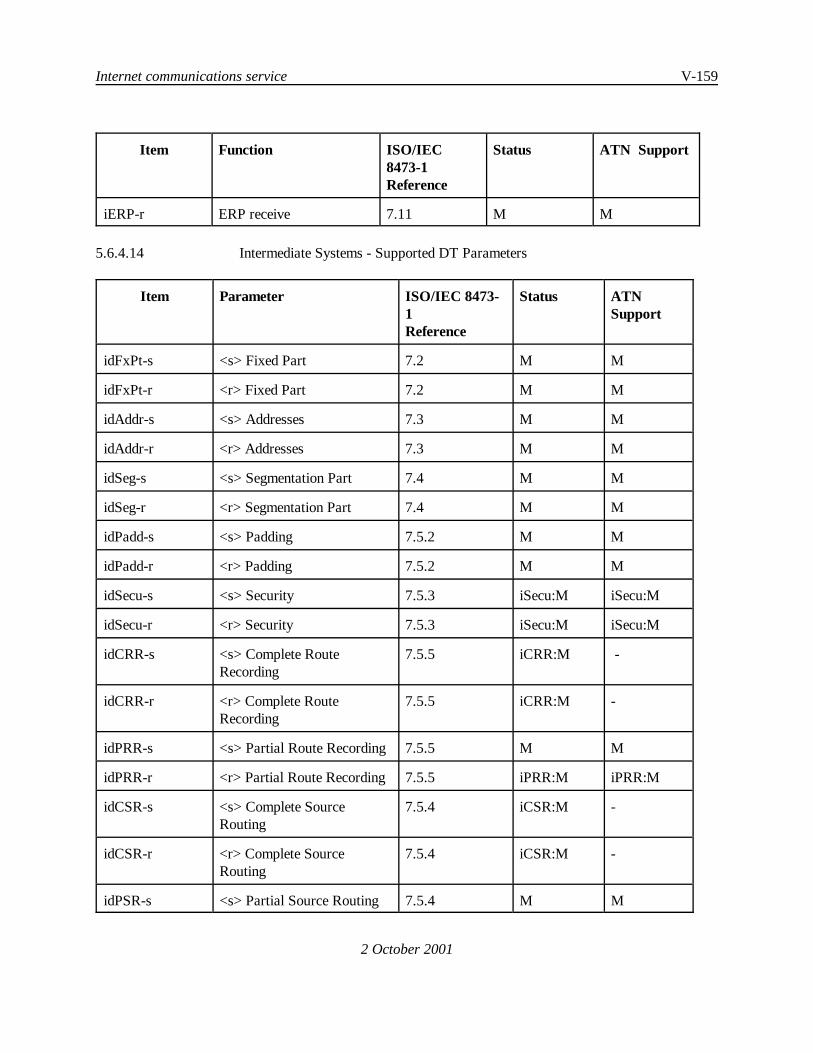
Internet communications service V-159
Item Function ISO/IEC8473-1Reference
Status ATN Support
2 October 2001
iERP-r ERP receive 7.11 M M
5.6.4.14 Intermediate Systems - Supported DT Parameters
Item Parameter ISO/IEC 8473-1Reference
Status ATNSupport
idFxPt-s <s> Fixed Part 7.2 M M
idFxPt-r <r> Fixed Part 7.2 M M
idAddr-s <s> Addresses 7.3 M M
idAddr-r <r> Addresses 7.3 M M
idSeg-s <s> Segmentation Part 7.4 M M
idSeg-r <r> Segmentation Part 7.4 M M
idPadd-s <s> Padding 7.5.2 M M
idPadd-r <r> Padding 7.5.2 M M
idSecu-s <s> Security 7.5.3 iSecu:M iSecu:M
idSecu-r <r> Security 7.5.3 iSecu:M iSecu:M
idCRR-s <s> Complete RouteRecording
7.5.5 iCRR:M -
idCRR-r <r> Complete RouteRecording
7.5.5 iCRR:M -
idPRR-s <s> Partial Route Recording 7.5.5 M M
idPRR-r <r> Partial Route Recording 7.5.5 iPRR:M iPRR:M
idCSR-s <s> Complete SourceRouting
7.5.4 iCSR:M -
idCSR-r <r> Complete SourceRouting
7.5.4 iCSR:M -
idPSR-s <s> Partial Source Routing 7.5.4 M M

V-160 Manual of Technical Provisions for the Aeronautical Telecommunication Network (ATN)
Item Parameter ISO/IEC 8473-1Reference
Status ATNSupport
2 October 2001
idPSR-r <r> Partial Source Routing 7.5.4 iPSR:M -
idQOSM-s <s> QOS Maintenance 7.5.6 M M
idQOSM-r <r> QOS Maintenance 7.5.6 iQOSM oriCong:M
iQOSM oriCong:M
idPri-s <s> Priority 7.5.7 M M
idPri-r <r> Priority 7.5.7 iPri:M iPri:M
idData-s <s> Data 7.6 M M
idData-r <r> Data 7.6 M M
idUnSup2 Are received PDUscontaining parametersselecting unsupported type 2functions discarded andwhere appropriate an ErrorReport PDU generated ?
6.19 M M
idUnSup3 Are parameters selectingunsupported Type 3functions ignored ?
6.19 M M
5.6.4.15 Intermediate Systems - Supported ER Parameters
Item Parameter ISO/IEC 8473-1 Reference
Status ATN Support
ieFxPt-s <s> Fixed Part 7.2 M M
ieFxPt-r <r> Fixed Part 7.2 M M
ieAddr-s <s> Address 7.3 M M
ieAddr-r <r> Address 7.3 M M
iePadd-s <s> Padding 7.5.2 M M
iePadd-r <r> Padding 7.5.2 M M
ieSecu-s <s> Security 7.5.3 iSecu:M iSecu:M

Internet communications service V-161
Item Parameter ISO/IEC 8473-1 Reference
Status ATN Support
2 October 2001
ieSecu-r <r> Security 7.5.3 iSecu:M iSecu:M
ieCRR-s <s> Complete RouteRecording
7.5.5 iCRR:M iCRR:M
ieCRR-r <r> Complete RouteRecording
7.5.5 iCRR:M -
iePRR-s <s> Partial RouteRecording
7.5.5 M M
iePRR-r <r> Partial RouteRecording
7.5.5 iPRR:M iPRR:M
ieCSR-s <s> Complete SourceRouting
7.5.4 iCSR:M -
ieCSR-r <r> Complete SourceRouting
7.5.4 iCSR:M -
iePSR-s <s> Partial Source Routing 7.5.4 M M
iePSR-r <r> Partial Source Routing 7.5.4 iPSR:M -
ieQOSM-s <s> QOS Maintenance 7.5.6 M M
ieQOSM-r <r> QOS Maintenance 7.5.6 iQOSM oriCong:M
iQOSM oriCong:M
iePri-s <s> Priority 7.5.7 M M
iePri-r <r> Priority 7.5.7 iPri:M iPri:M
ieDisc-s <s> Reason for Discard 7.9.5 M M
ieDisc-r <r> Reason for Discard 7.9.5 M M
ieData-s <s> Data 7.6 M M
ieData-r <r> Data 7.6 M M
ieUnsup2 Are received PDUscontaining parametersselecting unsupported type2 functions discarded ?
6.21 M M

V-162 Manual of Technical Provisions for the Aeronautical Telecommunication Network (ATN)
Item Parameter ISO/IEC 8473-1 Reference
Status ATN Support
2 October 2001
ieUnsup3 Are parameters selectingunsupported Type 3functions ignored ?
6.21 M M
5.6.4.16 Intermediate Systems - Supported ERQ Parameters
Item Parameter ISO/IEC8473-1Reference
Status ATN Support
iqFxPt-s <s> Fixed Part 7.2 M M
iqFxPt-r <r> Fixed Part 7.2 M M
iqAddr-s <s> Addresses 7.3 M M
iqAddr-r <r> Addresses 7.3 M M
iqSeg-s <s> Segmentation Part 7.4 M M
iqSeg-r <r> Segmentation Part 7.4 M M
iqPadd-s <s> Padding 7.5.2 M M
iqPadd-r <r> Padding 7.5.2 M M
iqSecu-s <s> Security 7.5.3 iSecu:M iSecu:M
iqSecu-r <r> Security 7.5.3 iSecu:M iSecu:M
iqCRR-s <s> Complete RouteRecording
7.5.5 iCRR:M M
iqCRR-r <r> Complete RouteRecording
7.5.5 iCRR:M -
iqPRR-s <s> Partial Route Recording 7.5.5 M M
iqPRR-r <r> Partial Route Recording 7.5.5 iPRR:M iPRR:M
iqCSR-s <s> Complete SourceRouting
7.5.4 iCSR:M -
iqCSR-r <r> Complete SourceRouting
7.5.4 iCSR:M -

Internet communications service V-163
Item Parameter ISO/IEC8473-1Reference
Status ATN Support
2 October 2001
iqPSR-s <s> Partial Source Routing 7.5.4 M M
iqPSR-r <r> Partial Source Routing 7.5.4 iPSR:M -
iqQOSM-s
<s> QOS Maintenance 7.5.6 M M
iqQOSM-r
<r> QOS Maintenance 7.5.6 iQOSM oriCong:M
iQOSM orICong:M
iqPri-s <s> Priority 7.5.7 M M
iqPri-r <r> Priority 7.5.7 iPri:M iPri:M
iqData-s <s> Data 7.6 M M
iqData-r <r> Data 7.6 M M
iqUnSup2 Are received PDUscontaining parametersselecting unsupported type 2functions discarded andwhere appropriate an ErrorReport PDU generated ?
6.19 M M
iqUnSup3 Are parameters selectingunsupported Type 3 functionsignored ?
6.19 M M
5.6.4.17 Intermediate Systems - Supported ERP Parameters
Item Parameter ISO/IEC 8473-1Reference
Status ATN Support
ipFxPt-s <s> Fixed Part 7.2 M M
ipFxPt-r <r> Fixed Part 7.2 M M
ipAddr-s <s> Addresses 7.3 M M
ipAddr-r <r> Addresses 7.3 M M
ipSeg-s <s> Segmentation Part 7.4 M M

V-164 Manual of Technical Provisions for the Aeronautical Telecommunication Network (ATN)
Item Parameter ISO/IEC 8473-1Reference
Status ATN Support
2 October 2001
ipSeg-r <r> Segmentation Part 7.4 M M
ipPadd-s <s> Padding 7.5.2 M M
ipPadd-r <r> Padding 7.5.2 M M
ipSecu-s <s> Security 7.5.3, ATNSARPs Ref:5.6.3.4.3,5.6.3.4.4
iSecu:M iSecu:M
ipSecu-r <r> Security 7.5.3, ATNSARPs Ref:5.6.3.4.3,5.6.3.4.4
iSecu:M iSecu:M
ipCRR-s <s> Complete RouteRecording
7.5.5 iCRR:M M
ipCRR-r <r> Complete RouteRecording
7.5.5 iCRR:M -
ipPRR-s <s> Partial Route Recording 7.5.5, ATNSARPs Ref:5.6.3.4.5
M M
ipPRR-r <r> Partial Route Recording 7.5.5, ATNSARPs Ref:5.6.3.4.5
iPRR:M iPRR:M
ipCSR-s <s> Complete SourceRouting
7.5.4 iCSR:M -
ipCSR-r <r> Complete SourceRouting
7.5.4 iCSR:M -
ipPSR-s <s> Partial Source Routing 7.5.4 M M
ipPSR-r <r> Partial Source Routing 7.5.4 iPSR:M -
ipQOSM-s <s> QOS Maintenance 7.5.6, ATNSARPs Ref:5.6.3.4.3,5.6.3.4.4
M M
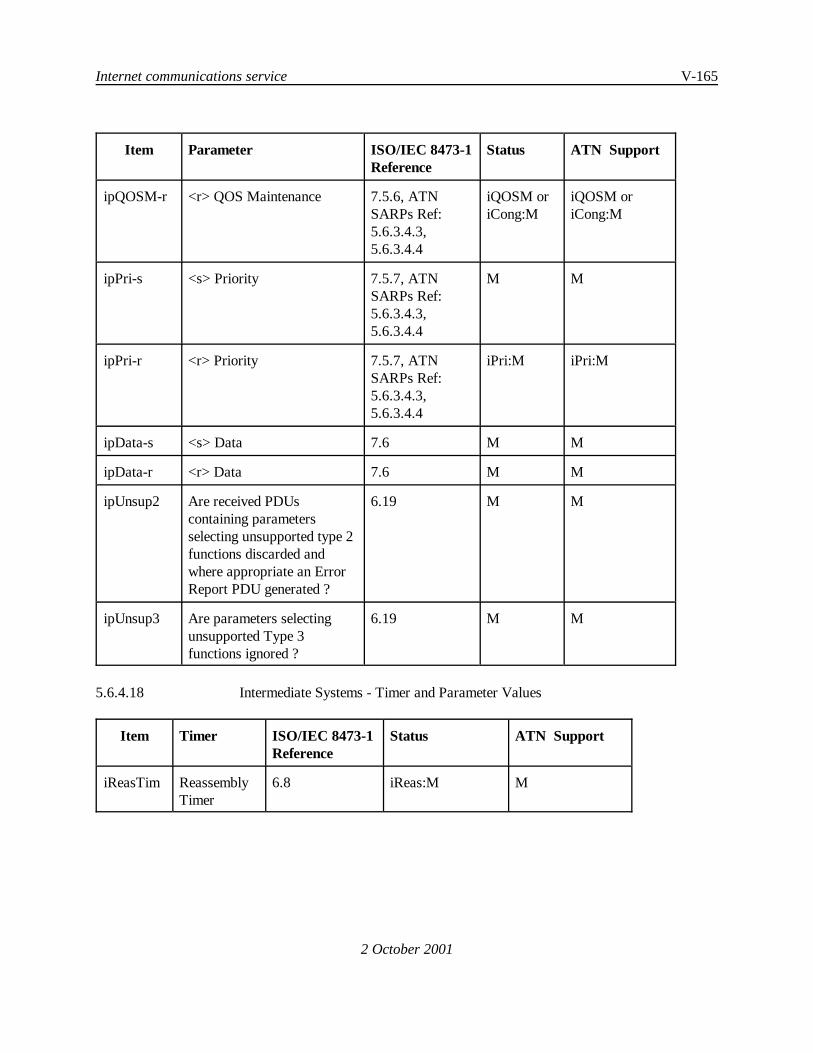
Internet communications service V-165
Item Parameter ISO/IEC 8473-1Reference
Status ATN Support
2 October 2001
ipQOSM-r <r> QOS Maintenance 7.5.6, ATNSARPs Ref:5.6.3.4.3,5.6.3.4.4
iQOSM oriCong:M
iQOSM oriCong:M
ipPri-s <s> Priority 7.5.7, ATNSARPs Ref:5.6.3.4.3,5.6.3.4.4
M M
ipPri-r <r> Priority 7.5.7, ATNSARPs Ref:5.6.3.4.3,5.6.3.4.4
iPri:M iPri:M
ipData-s <s> Data 7.6 M M
ipData-r <r> Data 7.6 M M
ipUnsup2 Are received PDUscontaining parametersselecting unsupported type 2functions discarded andwhere appropriate an ErrorReport PDU generated ?
6.19 M M
ipUnsup3 Are parameters selectingunsupported Type 3functions ignored ?
6.19 M M
5.6.4.18 Intermediate Systems - Timer and Parameter Values
Item Timer ISO/IEC 8473-1Reference
Status ATN Support
iReasTim ReassemblyTimer
6.8 iReas:M M

V-166 Manual of Technical Provisions for the Aeronautical Telecommunication Network (ATN)
2 October 2001
Figure 5.7-1 Relationship of SNDCFs to SN-Service and underlying Subnetworks
5.7 SPECIFICATION OF SUBNETWORK DEPENDENT CONVERGENCE FUNCTIONS
5.7.1 Introduction
Note 1.— The purpose of a Subnetwork Dependent Convergence Function (SNDCF) is to providethe connectionless SN-Service assumed by the ATN Internet Protocols over real subnetworks.
Note 2.— The Subnetwork Service (SN-Service) provided by an SNDCF and as specified in thisChapter is provided to the ISO/IEC 8473 Internetwork Protocol and the ISO/IEC 9542 End System toIntermediate System Protocol entities.
Note 3.— The ATN Internetwork Layer, including CLNP and the routing protocols that support it,assumes this common connectionless service to be provided by all subnetworks providing communicationsbetween ATN systems.
Note 4.— Figure 5.7-1 illustrates the relationships between the SNDCFs defined in this chapter, theSN-Service that they provide to CLNP and ES-IS, and the underlying subnetworks.
Note 5.— There is no requirement to implement this service as a software interface.

Internet communications service V-167
2 October 2001
5.7.2 Service Provided by the SNDCF
Note 1.— This section specifies the assumed service provided internally by the SNDCF for thepurpose of conveying Network Data PDUs between Network Entities.
Note 2.— The service to support SN-Service-Users is defined by the primitives in Table 5.7-1.
Table 5.7-1 SN-Services and Associated Parameters
Parameter SN-UNITDATA Request SN-UNITDATA Indication
SN-Source-Address Mandatory Mandatory
SN-Destination-Address Mandatory Mandatory
SN-Priority Optional Optional
SN-Quality-of-Service Optional Optional
SNS-Userdata Mandatory Mandatory
5.7.2.1 Subnetwork Service Primitive Parameters
Note.— The following sections specify the Subnetwork Service primitive parameters.
5.7.2.1.1 Subnetwork Point of Attachment (SNPA) Addresses
Note.— The SN-Source-Address and SN-Destination-Address parameters specify the points ofattachment to a public or private subnetwork(s). The SN-Source-Address and SN-Destination-Addressaddresses include information denoting a particular underlying subnetwork, as well as addressinginformation for systems attached directly to that subnetwork. SNPA values for a particular subnetwork arethose specified and administered by the authority responsible for administration of that subnetwork.
5.7.2.1.2 SN-Priority
Note 1.— The SN-Priority parameter indicates the relative importance of the associatedSNS-Userdata parameter, and may influence the order in which the SNS-Userdata are transferred via thereal underlying subnetwork service.
Note 2.— SN-Priority values are in the range zero to fourteen, with higher values indicating higherpriorities.
Note 3.— If no SN-Priority is indicated, the value zero is assumed to be the default.
Note 4.— Further requirements related to subnetwork priority are specified in 5.2.8.5.

V-168 Manual of Technical Provisions for the Aeronautical Telecommunication Network (ATN)
2 October 2001
5.7.2.1.3 Subnetwork Quality of Service (SNQoS)
Note 1.— The use of the SN-Quality-of-Service parameter is optional, and depends on the needs ofthe SN-Service-User.
Note 2.— Associated with each connectionless-mode transmission, certain measures of quality ofservice are requested when the SN-UNITDATA primitive action is initiated. These requested measures (orparameter values and options) are based on a priori knowledge of the service available from the subnetwork.Knowledge of the nature and type of service available is typically obtained prior to an invocation of theunderlying connectionless-mode service and the information passed is a local matter.
5.7.2.1.4 Subnetwork Service Userdata
Note 1.— The SNS-Userdata contains the ISO/IEC 8473 or ISO/IEC 9542 NPDU that has to beconveyed between adjacent network entities.
Note 2.— The SNS-Userdata is an ordered multiple of octets, and is transferred transparentlybetween the subnetwork points of attachment specified in the SNS primitive.

Internet communications service V-169
2 October 2001
5.7.3 SNDCF for ISO/IEC 8802-2 Subnetworks
Note.— ISO/IEC 8802-2 subnetworks are subnetworks that provide the logical link control sublayerservice defined by ISO/IEC 8802-2.
5.7.3.1 The SNDCF for use with ISO/IEC 8802-2 Subnetworks shall be implemented according toISO/IEC 8473-2.
5.7.3.2 APRLs
5.7.3.2.1 An implementation of the ISO/IEC 8802 SNDCF shall be used in ATN End Systems andRouters if and only if its PICS is in compliance with the APRLs given in 5.7.3.2.2 and 5.7.3.2.3.
5.7.3.2.2 Subnetwork Dependent Convergence Functions SNDCF for use with ISO/IEC8802-2Subnetworks - Functions
Item Function ISO/IEC 8473-2Reference
Status ATN Support
S802SNUD Is subnetwork user data of atleast 512 octets transferredtransparently by the SNDCF ?
5.2 M M
S802SNTD Is Transit Delay determined bythe SNDCF prior to theprocessing of User Data ?
5.2 M M
5.7.3.2.3 Subnetwork Dependent Convergence Functions SNDCF for use with ISO/IEC 8802-2Subnetworks - Multi Layer Dependencies
Item Dependency ISO/IEC 8473-2Reference
ATN Support
S802SSg-r <r> Maximum SN data unit size (RX) 5.2 >=512
S802SSg-s <s> Maximum SN data unit size (TX) 5.2 >=512

V-170 Manual of Technical Provisions for the Aeronautical Telecommunication Network (ATN)
2 October 2001
5.7.4 SNDCF for the Common ICAO Data Interchange Network (CIDIN)
5.7.4.1 General Considerations
Note 1.— The ISO/IEC 8473 Protocol assumes a Connectionless underlying subnetwork service.CIDIN provides a Connectionless Mode Service which is already very close to what is required by thisprotocol in the ATN.
Note 2.— This SNDCF maps to level 4 of CIDIN as specified in Annex 10, VolumeIII.
5.7.4.1.1 The SNDCF for CIDIN shall be as specified in the following sections.
5.7.4.2 SN-UNITDATA Request and Indication Primitives
5.7.4.2.1 These primitives shall correspond to the request to send a CIDIN message at a CIDIN entrycentre and the reception of a CIDIN message at a CIDIN exit centre respectively.
5.7.4.2.2 CIDIN messages shall be sent with the “no acknowledgement” option.
Note.— CIDIN messages requested to be transported to exit addresses which are not reachable arediscarded in the entry centre.
5.7.4.3 SN Source Address
5.7.4.3.1 This address shall correspond to a CIDIN entry address in the Entry Address item.
5.7.4.4 SN Destination Address
5.7.4.4.1 This address shall correspond to a CIDIN exit address in an Exit Address item.
5.7.4.5 SN Quality of Service
5.7.4.5.1 Apriori values for transit delay, protection against unauthorized access, cost determinantsand residual error probability shall be entered as management data in the ATN system.
5.7.4.6 SN Priority
5.7.4.6.1 The mapping between SN Priority and the CIDIN Subnetwork Priority shall be entered asmanagement data in the ATN system.
5.7.4.7 SNS-Userdata
5.7.4.7.1 SNS-Userdata shall be conveyed as the contents of the CIDIN message which is transportedtransparently by CIDIN.
Note.— The coding of the CIDIN message is code and byte independent.

Internet communications service V-171
2 October 2001
5.7.5 SNDCF for ISO/IEC 8208 General Topology Subnetworks
5.7.5.1 Over ISO/IEC 8208 General Topology Subnetworks, the subnetwork service described in5.7.2 shall beprovided using either theSNDCF for ISO/IEC 8208 General Topology Subnetworks as specifiedin ISO/IEC 8473-3, or the Mobile SNDCF specified below in 5.7.6.
Note.— Although most ATN Ground Systems are generally expected to use the ISO/IEC 8473-3specified SNDCF over ISO/IEC 8208 General Topology Subnetworks, Ground Systems may specify the useof the Mobile SNDCF, in order to improve the bandwidth utilisation over fixed ISO/IEC 8208 subnetworks.
5.7.5.2 Recommendation.— Implementations using the Mobile SNDCF as specified in 5.7.6 andthe LREF Compression Procedure for Ground/Ground communications, should also use the LREF optionallocal reference cancellation mechanism.
5.7.5.3 APRLs
5.7.5.3.1 An implementation of the SNDCF for ISO/IEC 8208 General Topology Subnetworks shallbe used in ATN End Systems and Routers if and only if its PICS is in compliance with the APRLs given in5.7.5.3.2 through 5.7.5.3.5.
5.7.5.3.2 Subnetwork Dependent Convergence Functions SNDCF for use with ISO/IEC8208Subnetworks - Functions
Item Function ISO/IEC 8473-3Reference
Status ATN Support
XSNUD Is Subnetwork User Data of at least512 octets transferred transparentlyby the SNDCF ?
5.2 M M
XSNTD Is Transit Delay determined by theSNDCF prior to the processing ofuser data ?
5.2 M M
Call Setup ConsiderationsIs a new call setup:
5.3.1
XCalla a. when no suitable call exists ? 5.3.1 a. O.3 O.3
XCallb b. when queue threshold reached ? 5.3.1 b. O.3 O.3
XCallc c. by systems management ? 5.3.1 c. O.3 O.3
XCalld d. when queue threshold reachedand timer expires ?
5.3.4 O.3 O.3
XCalle e. by other local means ? 5.3.1 O.3 O.3

V-172 Manual of Technical Provisions for the Aeronautical Telecommunication Network (ATN)
Item Function ISO/IEC 8473-3Reference
Status ATN Support
2 October 2001
Call Clearing ConsiderationsAre calls cleared:
5.3.2
XClra a. when idle timer expires ? 5.3.2 a., 5.3.4 O O
XClrb b. when need to re-use circuit ? 5.3.2 b. O O
XClrc c. by systems management ? 5.3.2 c. O O
XClrd d. by provider ? 5.3.2 d. M M
XClrer e. by other local means ? 5.3.2 O O
XPD X.25 Protocol Discrimination 5.3.3 M M
XVCC Resolution of VC collisions 5.3.5 M M
XMCR Multiple VCs responding 5.3.6 M M
XMCI Multiple VCs initiating 5.3.6 O O
Xpri X.25 Priority procedure 5.3.7 O M
5.7.5.3.3 Subnetwork Dependent Convergence Functions SNDCF for use with ISO/IEC8208Subnetworks - X.25 Call User Data
Item Parameter ISO/IEC 8473-3Reference
Status ATNSupport
PD-s <s> Protocol Discriminator 5.3.3 M M
PD-r <r> Protocol Discriminator 5.3.3 M M
LI-s <s> Length Indication 5.3.6 XMCI:M XMCI:M
LI-r <r> Length Indication 5.3.6 M M
Ver-s <s> SNCR Version 5.3.6 XMCI:M XMCI:M
Ver-r <r> SNCR Version 5.3.6 M M
SNCR-s <s> SNCR Value 5.3.6 XMCI:M XMCI:M
SNCR-r <r> SNCR Value 5.3.6 M M
5.7.5.3.4 Subnetwork Dependent Convergence Functions SNDCF for use with ISO/IEC8208Subnetworks - ISO/IEC 8208 SNDCF Timers

Internet communications service V-173
2 October 2001
Item Timer ISO/IEC 8473-3Reference
Status Values ATN Support
XIDL X25 VC Idle 5.3.4 XClra:O Any XClra:O
XNVC additional VC 5.3.4 O Any M
5.7.5.3.5 Subnetwork Dependent Convergence Functions SNDCF for use with ISO/IEC8208Subnetworks - SNDCF Multi Layer Dependencies
Item Dependency ISO/IEC 8473-3Reference
Status ValuesSupported
XSSg-r <r> Maximum SN data unit size (Rx) 5.2 >=512 >=512
XSSg-s <s> Maximum SN data unit size (Tx) 5.2 >=512 >=512
Item Dependency ISO/IEC 8473-3Reference
Status ATN Support
Xvc X.25 Virtual call service 5.3.8 M M
Xdt X.25 Data transfer 5.3.8 M M
Xfc X.25 flow control procedures 5.3.8 M M
Xfrp X.25 flow control + reset packets 5.3.8 M M
Xccp X.25 call setup and clear packets 5.3.8 M M
Xdp X.25 DTE and DCE data packets 5.3.8 M M
Xrs X.25 restart procedures 5.3.8 M M
XDct X.25 DCE timeouts 5.3.8 M M
XDtT X.25 time limits 5.3.8 M M
Xpco X.25 network packet coding 5.3.8 M M
Xfcn X.25 flow control parameter negotiation 5.3.8 O O
Xtd X.25 transit delay selection andnegotiation
5.3.8 O O
Xtc X.25 throughput class negotiation 5.3.8 O O
Xoth Other X.25 elements 5.3.8 O O
V-174 Manual of Technical Provisions for the Aeronautical Telecommunication Network (ATN)
2 October 2001
5.7.6 SNDCF for ISO/IEC 8208 Mobile Subnetworks
5.7.6.1 General
5.7.6.1.1 Over ISO/IEC 8208 Mobile Subnetworks, the subnetwork service described in 5.7.2 shall beprovided using the SNDCF for ISO/IEC 8208 Mobile Subnetworks as specified below.
Note 1.— The SNDCF specified below is only applicable when providing the SN-UNITDATA serviceto ISO/IEC 8473, ISO/IEC 9542, ISO/IEC 11577 and ISO/IEC 10589 Network Layer protocols.Unpredictable behavior may result if used to support other Network Layer Entities.
Note 2.— This SNDCF supports the following Data Compression Procedures:
C Local Reference (LREF) Compression as specified in 5.7.6.3;C Data Stream Mode Compression as specified in 5.7.6.5.
Note 3.— The Data Stream Mode Compression uses the Deflate algorithm which was originallyspecified in IETF RFC 1951.
Note 4.— Optional features of LREF Compression provide for “Local Reference Cancellation” andfor “Maintenance of the Local Reference Directory”. The mechanism for maintaining the Local ReferenceDirectory requires the support of the ISO/IEC 8208 Fast Select Facility.
Note 5.— Optional features of Data Stream Compression provide for “Negotiation of the Use of Pre-Stored Dictionaries” and for “Maintenance of the Deflate History Windows”. These mechanisms requirethe support of the ISO/IEC 8208 Fast Select Facility.
Note 6.— A Subnetwork Connection Group is the set of virtual circuits simultaneously active betweenthe same pair of DTEs, and which use the same subnetwork priority level, the same Data Compressionmechanism(s) and the same optional features of LREF Compression, if any.
Note 7.— When the LREF compression is used in the context of a Subnetwork Connection Group,the same Local Reference Directory (as defined in 5.7.6.3.1) is shared between all the virtual circuits of thisSubnetwork Connection Group.
Note 8.— If a Subnetwork Connection Group already exists with the same remote DTE and the samecompression mechanisms but with a different priority than the one used by the newly established virtualcircuit, this circuit may not use the Local Reference Directory of this group, as packets will not travel at thesame speed on two circuits which have different priorities.
Note 9.— The supported Data Compression Mechanisms and their options are negotiated when eachvirtual circuit used by the SNDCF is established. As a result of this negotiation, the virtual circuit is placedinto a new Subnetwork Connection Group or is inserted in an existing Subnetwork Connection Group.Negotiated Data Compression mechanisms and optional features of LREF Compression are applied on aSubnetwork Connection Group basis. This means that the same compression mechanism(s) and the sameLREF compression option(s) are used for all Virtual Circuits established in the context of the same

Internet communications service V-175
2 October 2001
Subnetwork Connection Group. Optional features of Data Stream compression areapplied on a VirtualCircuit basis. This means that Virtual Circuits established in the context of the same Subnetwork ConnectionGroup may use different Data Stream Compression options (e.g. different pre-stored dictionaries).
5.7.6.1.2 All ATN Intermediate Systems using Mobile ISO/IEC 8208 subnetworks for communicationwith other Intermediate Systems shall implement the LREF compression procedure.
5.7.6.1.3 Recommendation.— Implementations using this SNDCF for Air/Ground communicationsshould only implement the LREF optional facility for local reference cancellation when the lifetime of thevirtual circuits is of the same order as the flight time.
5.7.6.2 Call Setup
5.7.6.2.1 Calling DTE Procedures
5.7.6.2.1.1 General
5.7.6.2.1.1.1 When it has been determined that a virtual circuit is to be made available, the calling SNDCFshall establish the virtual circuit using the procedures specified in ISO/IEC 8208, either
a) dynamically, on receipt of a SN-UNITDATA request and when the SNDCF lacks asuitable virtual channel to the NPDU’s destination supporting the required priorityand QoS, or
b) by the explicit intervention of Systems Management, identifying the destinationSNDCF’s SNPA address, priority and QoS.
5.7.6.2.1.1.2 An ISO/IEC 8208 CALL REQUEST packet shall be sent to the DTE Address specified asthe SN-Destination-Address, with the following optional user facilities and CCITT-specified DTE facilities.
Note 1.— Normally, this is achieved by encoding the destination DTE Address as the called addressof the ISO/IEC 8208 Call Request packet. This is appropriate when the ATN Router is directly connectedto the air/ground subnetwork, or when it is connected to the air/ground subnetwork via another subnetworkand an interworking facility (ISO TR 10029). However, when the ATN Router is connected to the air/groundsubnetwork via another subnetwork and an interworking facility is not available, one possible alternativeapproach is to address the ISO/IEC 8208 Call Request packet to the access point of the air/groundsubnetwork (e.g. a GDLP) and to to convey the destination DTE Address in the Called Address Extensionfacility of the ISO/IEC 8208 Call Request packet whereas the DTE addresses configured for the local accesspoint of the air/ground subnetwork is encoded in the called address field of the ISO/IEC 8208 Call Requestpacket. It is then the responsibility of the air/ground subnetwork access facility to reformat the receivedISO/IEC 8208 Call Request packet into a Call Request packet appropriate for transmission to the destinationDTE address over the air/ground subnetwork.
Note 2.— Other optional user facilities and CCITT-specified DTE facilities may be required bysubnetworks. The use of these facilities is a local matter.

V-176 Manual of Technical Provisions for the Aeronautical Telecommunication Network (ATN)
2 October 2001
5.7.6.2.1.1.3 The Call Request user data shall be formatted as specified in 5.7.6.2.1.5.
5.7.6.2.1.2 The Priority Facility
5.7.6.2.1.2.1 The mapping of ATN network layer priorities to ATN mobile subnetwork priorities shall beas defined in 1.3.8 for those mobile subnetworks subject to ICAO standards.
5.7.6.2.1.2.2 For mobile subnetworks not subject to ICAO standards, the Priority Facility shall be used ifthe subnetwork provider supports prioritisation of Virtual Circuits and specifies the mapping of NetworkService to Subnetwork Service priorities.
5.7.6.2.1.2.3 The priority value passed in the SN-UNITDATA request or indicated by the System Managershall be mapped to priority of data on a connection, as specified by the Subnetwork Provider.
5.7.6.2.1.2.4 If the priority to gain a connection and/or priority to keep a connection is conveyed within theISO/IEC 8208 Facility Parameter Field, these priorities shall be consistent with the priority of data on aconnection, and set according to the Subnetwork Provider*s guidelines.
Note 1.— The SNDCF is assumed to know, a priori, if a given subnetwork supports prioritisationof virtual circuits, the number of discrete priority levels supported and the relationship between thesubnetwork priority and SNSDU priority.
Note 2.— The mapping between SNSDU priority and subnetwork priority is specified separately foreach subnetwork type.
5.7.6.2.1.3 Non-Standard Default Packet Size Facility and Flow Control Parameter Negotiation Facility
5.7.6.2.1.3.1 Either the Non-standard Default Packet Size Facility or the Flow Control ParameterNegotiation Facility shall be used to request the maximum packet size supported by the subnetwork.
Note.— The selection of which facility to use is dependent on the facilities supported by thesubnetwork.
5.7.6.2.1.4 The Fast Select Facility
5.7.6.2.1.4.1 The Fast Select Facility shall be used if supported by all Subnetwork Provider(s) in theDTE-DTE virtual path.
Note.— Airborne routers are assumed to have a priori knowledge of Fast Select support (or lackthereof) along the DTE-DTE virtual path based on each individual destination air/ground router´s DTEaddress.
5.7.6.2.1.4.2 No restriction on response shall be indicated.
Note 1.— This permits the responding DTE accept the call and to return up to 128 octets of userdata.

Internet communications service V-177
2 October 2001
Figure 5.7-2 Format for Call Request User Data
Note 2.— If Fast Select is not supported, the Compression Procedures can only be negotiated bysuccessive attempts to establish the virtual circuit requesting different combinations of CompressionProcedures.
5.7.6.2.1.5 Call Request User Data
Note.— Call Request User Data is used to indicate which Compression Procedures are offered bythe calling DTE. When the Fast Select Facility is used, Call Accept User Data is then used to indicate whichCompression Procedures are accepted by the Called DTE.
5.7.6.2.1.5.1 The Call Request User Data format shall be as illustrated in Figure 5.7-2.
5.7.6.2.1.5.2 The first octet of the call user data (the Subsequent Protocol Identifier (SPI)) shall be set tobinary [1100 0001] to indicate that the virtual circuit is to be used to provide the underlying service by thisSNDCF.
Note.— ISO TR 9577 provides the international register for SPI values. The value binary [11000001] has not been assigned by the ISO Technical Report and it is unlikely that it will be.

V-178 Manual of Technical Provisions for the Aeronautical Telecommunication Network (ATN)
2 October 2001
5.7.6.2.1.5.3 The second octet is the length indicator of the subsequent SNDCF Parameter Block and itsvalue shall be an unsigned binary number giving the number of octets in the SNDCF Parameter Block (fromversion number field up to and including (if present) the maximum number of directory entries field).
5.7.6.2.1.5.4 SNDCF Parameter Block
Note.— The SNDCF Parameter Block contains a fixed part and an optional part. The fixed part is4 octets long and is always present; it contains the parameters Version Number, Subnetwork ConnectionReference (SNCR), and Compression Techniques. The optional part is 1 or 2 octets long; it is present if theLREF Compression algorithm is offered and is used to define the maximum directory size of the LREFdirectory.
5.7.6.2.1.5.4.1 The first octet of the SNDCF Parameter Block is the SNDCF Version Number and shall beset to [0000 0010], if the Call Request User Data contains an SNDCF Extension Parameter Block (see5.7.6.2.1.5.5), and to [0000 0001] otherwise.
Note 1.— The value [0000 0001] indicates the first version of the SNDCF protocol. This versionis compliant with the SNDCF provisions contained in previous editions of this specification.
Note 2.— The value [0000 0010] indicates the second version of the SNDCF protocol which hasbeen added to the 3rd edition of this specification.
5.7.6.2.1.5.4.1.1 When a Subnetwork Connection Group with the called DTE already exists, then the SNDCFVersion Number, which has been used to establish this Subnetwork Connection Group, shall also be used whenestablishing any further virtual circuit within this group and the Call Request User Data be formated accordingto this SNDCF version number.
Note.— The use of the second version of the SNDCF protocol has to be avoided when it can be apriori known that the called DTE only supports a lower version of the protocol. Such a priori knowledgeexists for example, when the called DTE has previously rejected a call with a Diagnostic Code indicating“Version number not supported”.
5.7.6.2.1.5.4.1.2Recommendation.—The version number of the SNDCF protocol used by the calling DTEwhen initiating a Call Request should be configurable.
5.7.6.2.1.5.4.2 The second and third octets of the SNDCF Parameter Block shall provide the low order andhigh order octet respectively of the Subnetwork Connection Reference (SNCR).
5.7.6.2.1.5.4.3 The value encoded in this field shall be the lowest available SNCR value in the range from 0up to one less than the number of virtual circuits needed at this call priority.
Note.— The use of the SNCR is specified in ISO/IEC 8473 for use in call collision resolution overISO/IEC 8208 subnetworks.
5.7.6.2.1.5.4.4 The fourth octet of the SNDCF Parameter Block shall indicate the compression techniquesoffered by the calling DTE, according to Table 5.7-2 and Figure 5.7-2.

Internet communications service V-179
2 October 2001
5.7.6.2.1.5.4.5 Thosebits of Table5.7-2 and Figure5.7-2 which are marked as ‘Spare’ arereserved for futureuse by this specification and shall always be set to zero.
Table 5.7-2 Compression Options Offered Parameter
Bit number Option
bit 8 Spare
bit 7 Note.— In earlier versions of thisspecification this bit was used to indicate theICAO Address Compression Algorithm (ACA).To ensure backwards compatibility with theseversions an incoming call with bit 7 set to 1will be rejected indicating the diagnostic value135 (see Table 5.7-4).
bit 6 Deflate
bit 5 Maintenance/Initiation of Local ReferenceDirectory (M/I) option
bit 4 Spare
bit 3 Spare
bit 2 Local Reference (LREF) option
bit 1 Local Reference Cancellation (CAN) optionsupported
5.7.6.2.1.5.4.6 LREF Compression shall always be offered.
Note 1.— This specification mandates the use of the LREF Compression algorithm. This may notbe true in future editions of this specification. Hence procedures are specified to negotiate the use of theLREF Compression on a per virtual circuit basis.
Note 2.— The decision as regards which options to offer out of those supported is otherwise a localmatter.
Note 3.— Multiple compression procedures may be offered.
5.7.6.2.1.5.4.7 Bit 1 of the fourth octet of the SNDCF Parameter Block shall only be set if bit 2 is also set.
5.7.6.2.1.5.4.8 Bit 5 (M/I bit) of the fourth octet of the SNDCF Parameter Block shall be set to one by thecalling SNDCF when the calling SNDCF has identified a Subnetwork Connection Group with the called DTE,with therequested subnetwork priority and with thesame Data Compression mechanisms and the same optional

V-180 Manual of Technical Provisions for the Aeronautical Telecommunication Network (ATN)
2 October 2001
features of LREF Compression, to request that the newly established circuit shares the Local ReferenceDirectory associated with this group.
5.7.6.2.1.5.4.9 The request for Local Reference directory maintenance shall only be used when the CallRequest uses the Fast Select Facility and when bit 2 of the Compression Options Parameter (Local Referencecompression) is set to one.
5.7.6.2.1.5.4.10 When the request for Local Reference directory maintenance is used, then theSubnetwork Connection Reference (SNCR) of the Call Request packet shall be set to the lowest availableSNCR value in the range from 0 up to one less than the number of virtual circuits needed at this call priority.
5.7.6.2.1.5.4.11 When the LREF Compression algorithm is offered, i.e if bit 2 in the fourth octet ofthe SNDCF Parameter Block is set, then the value of the fifth and sixth octets (Maximum Directory Entries)shall be an unsigned even binary number indicating the maximum number of directory entries supported forthe local reference (minimum size 128).
5.7.6.2.1.5.4.12 Bit 2 of the fourth octet of the SNDCF Parameter Block shall be set to zero.
5.7.6.2.1.5.5 SNDCF Parameter Extension Block
Note.— The optional SNDCF Parameter Extension Block has a variable length and is used to conveyparameters related to advanced compression features, such as use of pre-stored Data Stream CompressionDictionaries and maintenance of the Deflate Compression History Window. Parameters defined in thisExtension Block may appear in any order.
5.7.6.2.1.5.5.1 When the SNDCF Parameter Extension Block is present, then the first octet of this block shallbe the octet immediately following the SNDCF Parameter Block.
5.7.6.2.1.5.5.2 The first octet of the SNDCF Parameter Extension Block is the length indicator of this blockand shall indicate the number of octets in the SNDCF Parameter Extension Block (including its length indicatorfield) as an unsigned binary number with a maximum value of 121.
5.7.6.2.1.5.5.3 Each parameter contained within the SNDCF Parameter Extension Block shall be structuredas illustrated in Figure 5.7-3.
Octets Semantics
1 Parameter Code
2 Parameter Length Indication
3 ... m Parameter Value
Figure 5.7-3 Format of Parameters in the SNDCF Parameter Extension Block
5.7.6.2.1.5.5.4 The Parameter Code field shall be coded in binary.

Internet communications service V-181
2 October 2001
5.7.6.2.1.5.5.5 There shall be no more than one parameter with the same Parameter Code in the SNDCFParameter Extension Block.
5.7.6.2.1.5.5.6 The Parameter Length Indication field shall indicate the number of octets of the ParameterValue field.
5.7.6.2.1.5.5.7 Dictionaries List Parameter
5.7.6.2.1.5.5.7.1 When the use of pre-stored Data Stream Compression dictionaries is supported, the SNDCFParameter Extension Block shall include a Dictionaries List Parameter if the following conditions are satisfied:
a) the Deflate Compression algorithm is offered, i.e. bit 6 in the fourth octet of theSNDCF Parameter Block is set, and
b) the Call Request uses the Fast Select Facility.
5.7.6.2.1.5.5.7.2 The Dictionaries List Parameter shall be encoded as defined in 5.7.6.2.1.5.9.
5.7.6.2.1.5.5.8 Deflate Maintenance Parameter
5.7.6.2.1.5.5.8.1 When the option for the Maintenance of the Deflate History Windows is supported, theSNDCF Parameter Extension Block shall include a Deflate Maintenance Parameter, if all of the followingconditions are satisfied:
a) the Deflate Compression algorithm is offered, i.e. bit 6 in the fourth octet of theSNDCF Parameter Block is set;
b) a Subnetwork Connection Group already exists with the same remote DTE, with therequested subnetwork priority and with the same Data Compression mechanisms andthe same optional features of LREF Compression;
c) the values of bit 2 (LREF option) and bit 5 (M/I option) in the fourth octet of theSNDCF Parameter Block are equal (i.e. both bits are set to 0 or both bits are set to1);
d) the Call Request uses the Fast Select Facility.
5.7.6.2.1.5.5.8.2 The Deflate Maintenance Parameter shall be encoded as defined in 5.7.6.2.1.5.10.
5.7.6.2.1.5.6 When the Call Request User Data contains an SNDCF Parameter Extension Block, then theoctet following the SNDCF Parameter Extension Block shall be the first octet of the User Data field, if present.
5.7.6.2.1.5.7 Otherwise, the octet following the SNDCF Parameter Block shall be the first octet of the UserData field, if present.

V-182 Manual of Technical Provisions for the Aeronautical Telecommunication Network (ATN)
2 October 2001
5.7.6.2.1.5.8 The information in the User Data field of the Call Request User Data shall not be compressed.When the fast select facility is available, the User Data field may be used to convey the ISO/IEC9542 ISHPDU as part of the routing initiation sequence.
5.7.6.2.1.5.9 Encoding of the Dictionaries List Parameter
5.7.6.2.1.5.9.1 The Dictionaries List Parameter shall be structured as illustrated in Figure 5.7-3.
5.7.6.2.1.5.9.2 The Parameter Code field of the Dictionaries List Parameter shall be set to [0000 0001].
5.7.6.2.1.5.9.3 The Parameter Value field of the Dictionaries List Parameter shall consist of one or moreDictionary Tags, as defined in 5.7.6.2.1.5.9.7, identifying the latest supported version of the Data StreamCompression Dictionaries supported by the calling DTE.
5.7.6.2.1.5.9.4 A calling DTE shall only indicate support of a given version of a Data Stream CompressionDictionary, if it also supports all previous versions of the same Data Stream Compression Dictionary.
5.7.6.2.1.5.9.5 Within the Dictionaries List Parameter Value field, the Dictionary Tags shall appear in theorder of preference of the calling DTE, whereby the first Dictionary Tag identifies the most preferreddictionary.
5.7.6.2.1.5.9.6 Within the Dictionaries List Parameter Value field, there shall be no duplication of aDictionary Tag.
5.7.6.2.1.5.9.7 Encoding of the Dictionary Tag
Note 1.— A Dictionary Tag uniquely identifies a Data Stream Compression Dictionary.
Note 2.— A Data Stream Compression Dictionary consists of an octetstring of frequently usedsymbols in the uplink direction and of an octetstring of frequently used symbols in the downlink direction.Each of these two octetstrings may be up to 32KB long.
5.7.6.2.1.5.9.7.1 A Dictionary Tag shall be two octets in length.
5.7.6.2.1.5.9.7.2 The two most significant bits of the first octet of a Dictionary Tag shall identify theRegistration Authority of the Data Stream Compression Dictionary, as indicated in Table 5.7-3.
Table 5.7-3 Encoding of the First Octet of a Dictionary Tag
Bit 8 Bit 7 Registration Authority
0 0 ICAO
0 1 IATA
1 0 Reserved

Internet communications service V-183
Bit 8 Bit 7 Registration Authority
2 October 2001
1 1 Reserved
5.7.6.2.1.5.9.7.3 The six least significant bits of the first octet of a Dictionary Tag shall identify one DataStream Compression Dictionary registered by the Registration Authority identified by the two most significantbits.
Note.— At present, no Data Stream Compression Dictionary has been registered by ICAO.
5.7.6.2.1.5.9.7.4 The second octet of a Dictionary Tag shall be an unsigned binary number in the range[01-FF] (hexadecimal) identifying the latest version of this Data Stream Compression Dictionary beingsupported by the ATN Router.
5.7.6.2.1.5.10 Encoding of the Deflate Maintenance Parameter
5.7.6.2.1.5.10.1 The Deflate Maintenance Parameter shall be structured as illustrated in Figure 5.7-3.
5.7.6.2.1.5.10.2 The Parameter Code of the Deflate Maintenance Parameter shall be set to [00000010].
5.7.6.2.1.5.10.3 The Parameter Length field of the Deflate Maintenance Parameter shall be set to 4.
5.7.6.2.1.5.10.4 The Parameter Value field of the Deflate Maintenance Parameter shall be a 4 octets-long unsigned binary number that is encoded least significant byte first, least significant bit first.
5.7.6.2.1.5.10.5 The Parameter Value field of the Deflate Maintenance Parameter shall be set to theabsolute value of the upper edge of the decompressor history window being maintained over this subnetworkconnection group.
Note.—The absolute value of the upper edge of the decompressor history window is defined in5.7.6.5.9.3.
5.7.6.2.1.5.11 Procedure Associated with the Use of the Deflate Maintenance Parameter
5.7.6.2.1.5.11.1 When the Maintenance of the Deflate History Window option is offered, the callingDTE shall duplicate the decompressor history window currently used for Deflate compression over the lastVirtual Circuit established in the context of the Subnetwork Connection Group, and register this copy as theinitial decompressor history window to be used for Deflate decompression over the Virtual Circuit beingestablished.
Note.— A physically separate copy is required because the content of the history windows of thepreceeding Virtual Circuit in that Subnetwork Connection Group may still evolve while the new VirtualCircuit is being established.

V-184 Manual of Technical Provisions for the Aeronautical Telecommunication Network (ATN)
2 October 2001
5.7.6.2.1.6 Receipt of “Call Confirm Packet”
5.7.6.2.1.6.1 Fast Select Facility In Use
5.7.6.2.1.6.1.1 When an ISO/IEC 8208 Call Confirm Packet is received from the Called DTE and the FastSelect Facility is in use, then the Calling DTE shall inspect the first octet of the received Call Confirm UserData (see 5.7.6.2.2.4.3) in order to determine which of the offered Compression Procedures have been acceptedand whether the Call Confirm User Data contains an SNDCF Parameter Extension Block.
5.7.6.2.1.6.1.2 If the called SNDCF has accepted the call indicating that an offered Compression Procedureis not supported, then the Calling SNDCF shall maintain the virtual circuit and shall not apply this compressionprocedure.
5.7.6.2.1.6.1.3 If the M/I bit is set to zero in the first octet of the Call Confirm User Data and if a DeflateMaintenance Parameter is not present in the SNDCF Parameter Extension Block, then a new SubnetworkConnection Group shall be created and the newly established virtual circuit becomes the first member of thatgroup.
5.7.6.2.1.6.1.4 If the M/I bit is set to one in the first octet of the Call Confirm User Data and the M/I bit inthe preceding Call Request had also been set to one, then the newly established virtual circuit shall be insertedinto the Subnetwork Connection Group identified when the Call Request was issued.
5.7.6.2.1.6.1.5 If the M/I bit is set to one in the first octet of the Call Confirm User Data, and M/I bit had beenset to zero in the preceding Call Request, then this is an error condition, and the call shall be cleared with anISO/IEC 8208 Cause Code of zero, and a diagnostic code of 242 (Disconnection - incompatible informationin user data).
5.7.6.2.1.6.1.6 If the PEXT bit is set to zero in the first octet of the Call Confirm User Data and a SNDCFParameter Extension Block containing a Dictionaries List Parameter or a Deflate Maintenance Parameterrespectively was present in the associated Call Request User Data, then the calling SNDCF shall assume thatnone of the proposed dictionaries has been accepted by the called SNDCF and/or that the called SNDCF hasnot accepted to maintain the Deflate History Windows respectively.
5.7.6.2.1.6.1.7 If the PEXT bit is set to one in the first octet of the Call Confirm User Data, then the CallConfirm User Data contains an SNDCF Parameter Extension Block and the calling SNDCF shall process thisParameter Extension Block as specified in 5.7.6.2.1.6.1.11.
5.7.6.2.1.6.1.8 If the PEXT bit in the first octet of the received Call Confirm User Data
a) is set to one and the length of the Call Confirm User Data is greater than the value ofthe first octet of the received SNDCF Parameter Extension Block (i.e. lengthindicator) plus 1, or
b) is not set to one and the length of the Call Confirm User Data is greater than one

Internet communications service V-185
2 October 2001
then the received Call Confirm User Data contains additional data, and the calling SNDCF shall inspect thefirst octet of the User Data field (see Figure 5.7-4) whether it contains a recognized NPDU SPI.
Note.— The additional data, if any, is processed without performing any of the decompressionmechanisms that may have been negotiated.
5.7.6.2.1.6.1.9 If the inspected octet contains a recognized NPDU SPI, then the calling SNDCF shall passthis octet and the remaining part of the received Call Confirm User Data (i.e. the NPDU) in an SN-UNITDATAindication to the appropriate SN-Service User, using the received SPI to identify the network layer protocol,and hence which SN-Service User is responsible for handling this NPDU.
5.7.6.2.1.6.1.10 If no such SN-Service user exists or the inspected octet does not contain a recognizedNPDU SPI, then the additional data in the Call Confirm User Data shall be discarded.
5.7.6.2.1.6.1.11 Processing of SNDCF Parameter Extension Block
5.7.6.2.1.6.1.11.1 If the SNDCF Parameter Extension Block contains an unknown optional parameter, thenthis parameter shall be ignored but the received ISO/IEC8208 Call Confirm Packet not be discarded.
5.7.6.2.1.6.1.11.2 If a Deflate Maintenance Parameter is present in the SNDCF Parameter Extension Block,the following cases are error conditions:
a) The preceeding Call Request did not convey any Deflate Maintenance Parameter;
b) Bit 6 (i.e. Deflate bit) of the first octet of the Call Confirm User Data is not set;
c) The values of bit 2 (LREF option) and bit 5 (M/I option) of the first octet of the CallConfirm User Data are not equal;
d) A Dictionary Selection Parameter is also present in the SNDCF Parameter ExtensionBlock;
e) More than one Deflate Maintenance Parameter is present in the SNDCF ParameterExtension Block;
and shall be handled by clearing the call with an ISO/IEC 8208 Cause Code of zero, and a Diagnostic Codeof 242 (i.e. Disconnection - incompatible information in user data).
5.7.6.2.1.6.1.11.3 If the value of the Deflate Maintenance Parameter is such that the position of the upperedge of the remote DTE decompressor window is indicated to be higher than the position of theupper edge ofthe local compressor window, then:
a) the calling DTE shall clear the Virtual Circuit with a cause code set to zero, and adiagnostic code set to 242 (i.e Disconnection - incompatible information in user data);
b) The calling DTE shall then re-attempt to establish the Virtual Circuit withoutproposing maintenance of the Deflate history windows;

V-186 Manual of Technical Provisions for the Aeronautical Telecommunication Network (ATN)
2 October 2001
c) This error condition shall be reported to Systems Management.
Note.— Because of wrap around, implementors must treat the term "higher" with a certain degreeof caution.
5.7.6.2.1.6.1.11.4 If a Deflate Maintenance Parameter is present in the SNDCF Parameter Extension Blockand if none of the above error conditions is encountered, then the newly established virtual circuit shall beinserted into the Subnetwork Connection Group identified when the Call Request was issued.
5.7.6.2.1.6.1.11.5 Then the calling DTE shall duplicate the compressor history window currently usedfor Deflate compression over the last Virtual Circuit established in the context of the Subnetwork ConnectionGroup, and register this copy as the initial compressor history window to be used for Deflate compression overthe Virtual Circuit being established.
5.7.6.2.1.6.1.11.6 Then the compressor history window that has been associated with the newly establishedvirtual circuit shall be resynchronized with the decompressor history window of the remote DTE, by settingthe compressor history windowupper edge to the value of the remote decompressor windowupper edge thatis indicated by the value of the Deflate Maintenance Parameter.
5.7.6.2.1.6.1.11.7 If, as a consequence of the above procedure, the lower edge of the compressor historywindow becomes greater than the newupper edge, then the lower edge shall be aligned with the new upper edge.
Note.— This may occur when the octet of history data pointed by the upper edge of the remotedecompressor history window is ouside the local compressor window. As a result of this procedure, the localcompressor window is reset to a void state, and maintenance of the history window has failed. However, thelower and upper edges of the local compressor window are resynchronized with the upper edge of the remotedecompressor window, and this will allow to re-attempt the maintenance of the Deflate compression whena next virtual circuit is created in the context of this Subnetwork Connection Group.
5.7.6.2.1.6.1.11.8 If a Dictionary Selection Parameter is present in the SNDCF Parameter Extension Block,the following cases are error conditions:
a) The preceeding Call Request did not convey any Dictionaries List Parameter;
b) Bit 6 (i.e. Deflate option) of the first octet of the Call Confirm User Data is not set;
c) A Deflate Maintenance Parameter is also present in the SNDCF Parameter ExtensionBlock;
d) More than one Dictionary Selection Parameter is present in the SNDCF ParameterExtension Block;
e) The Dictionary Tag conveyed in the Dictionary Selection Parameter does not identifythe same version or an older version of one of the Data Stream CompressionDictionaries that have been proposed in the Dictionaries List Parameter conveyed inthe preceding Call Request;
Internet communications service V-187
2 October 2001
and shall be handled by clearing the call with an ISO/IEC 8208 Cause Code of zero, and a Diagnostic Codeof 242 (Disconnection - incompatible information in user data).
5.7.6.2.1.6.1.11.9 If a Dictionary Selection Parameter is present in the SNDCF Parameter Extension Blockand if none of the above error conditions is encountered, then the compressor and decompressor historywindows of the newly established Virtual Circuit shall be initialized with the content of the Dictionary that isidentified by the Dictionary Selection Parameter.
5.7.6.2.1.6.2 Fast Select Facility not in Use
5.7.6.2.1.6.2.1 When an ISO/IEC 8208 Call Confirm Packet is received from the Called DTE and the FastSelect Facility is not in use, then the Calling DTE shall assume that all of the offered Compression Procedureshave been accepted.
5.7.6.2.1.7 Call Rejection by the DCE or Called DTE
5.7.6.2.1.7.1 General
5.7.6.2.1.7.1.1Recommendation.—When a DTE originated ISO/IEC 8208 Call Clearing Packet isreceived with a diagnostic value indicating that the proposed LREF directory is too big (see Table 5.7-4),then the call should be re-attempted with the minimum directory size (see 5.7.6.3.1.3).
Note.— This is to ensure that the call is not rejected again due to the requested directory size beingtoo big.
5.7.6.2.1.7.1.2 If the diagnostic indicates Call Collision resolution then no further attempt shall be made tore-establish the call.
5.7.6.2.1.7.1.3 When a DTE originated ISO/IEC 8208 Call Clearing packet is received with a diagnostic valueindicating “Version number not supported” (see Table 5.7-4), then the call shall be re-attempted with a versionnumber in the SNDCF Parameter Block of the Call Request User Data (see 5.7.6.2.1.5.4.1) which is one lessthan previously used.
Note.— This failure condition may occur if the calling ATN Router supports a later edition of thisspecification than the called ATN Router.
5.7.6.2.1.7.2 Fast Select Facility Requested
5.7.6.2.1.7.2.1 When a DCE or DTE originated ISO/IEC 8208 Call Clearing Packet is received with adiagnostic indicating Fast Select not Subscribed or Fast Select Acceptance Not Subscribed, then the call shallbe re-attempted but without requesting the Fast Select Facility.
Note.— Some Network Service Providers may indicate the non availability of the Fast Select Facilityvia other diagnostic codes.

V-188 Manual of Technical Provisions for the Aeronautical Telecommunication Network (ATN)
2 October 2001
5.7.6.2.1.7.3 Fast Select Facility not in Use
Note.— In this case, when rejection by the called DTE indicates that the reject reason is due to anoffered compression procedure not being supported, then the call is re-attempted without offering the rejectedprocedure. This is the only negotiation procedure possible when Fast Select is not available.
5.7.6.2.1.7.3.1 When a DTE originated ISO/IEC 8208 Call Clearing Packet is received with a diagnosticindicatingLREF Compression not Supported(see Table 5.7-4), the call shall be re-attempted without offeringLREF Compression.
5.7.6.2.1.7.3.2 When a DTE originated ISO/IEC 8208 Call Clearing Packet is received with a diagnosticindicatingLocal Reference Cancellation not Supported(seeTable5.7-4), thecall shall bere-attempted withoutoffering Local Reference Cancellation.
5.7.6.2.1.7.3.3 When a DTE originated ISO/IEC 8208 Call Clearing Packet is received with a diagnosticindicatingDeflate compression not Supported(see Table 5.7-4), the call shall bere-attempted without offeringDeflate compression.
5.7.6.2.2 Called DTE Procedures
5.7.6.2.2.1 Incoming Call Processing
5.7.6.2.2.1.1 When an ISO/IEC 8208 Incoming Call Packet is received, the called SNDCF first shall checkfor a call collision.
5.7.6.2.2.1.2 If the SNDCF has an outstanding Call Request to the same DTE Address, specified as thecalling DTE in this Incoming Call Packet, and the call priority and SNCR are identical, then a call collisionhas occurred, and the call collision resolution procedures specified in ISO/IEC8473-3 shall be invoked toresolve the call collision.
5.7.6.2.2.1.3 The called SNDCF shall then determine whether to accept the call.
5.7.6.2.2.1.4 The call shall be rejected if any of the following conditions are true:
a) The proposed ISO/IEC 8208 facility is not available;
b) The proposed priority is not supported;
c) The Fast Select Facility was not selected in the Incoming Call Packet and an offeredcompression algorithm is not supported;
d) The format of the call user data is invalid;
e) The version number is not supported;
Internet communications service V-189
2 October 2001
f) The Local Reference compression is offered and the called SNDCF does not supportthe proposed directory size;
g) Local Policy does not permit communication with the calling DTE.
5.7.6.2.2.1.5 The call shall then be rejected using a Call Clearing Packet, with the appropriate diagnosticcode, as listed in Table 5.7-4.
5.7.6.2.2.1.6 If the call is to be accepted then the Called SNDCF shall perform the ISO/IEC 8208procedures associated with accepting a call.
5.7.6.2.2.2 Call Acceptance with the Fast Select Facility in Use
5.7.6.2.2.2.1 The combination of compression techniques acceptable to the SNDCF, out of those offeredby the Calling SNDCF, shall be indicated by setting the appropriate bits in the first octet of the ISO/IEC8208Call Accept User Data as shown in Figure 5.7-4.
5.7.6.2.2.2.2 Paragraph has been deleted.
5.7.6.2.2.2.3 If the M/I bit is set to one in the Call Request User Data and,
a) there is one and only one existing Subnetwork Connection Group with the callingDTE with the same Data Compression mechanisms and the same optional featuresof LREF compression as indicated in the Call Request User Data, and the requestedpriority, and
b) it is acceptable to share the Local Reference Directory associated with thisSubnetwork Connection Group with this virtual circuit,
then the virtual circuit shall be inserted in this Subnetwork Connection Group and the M/I bit set to one in theCall Accept User Data.
5.7.6.2.2.2.4 Otherwise, and if the Virtual Circuit is not inserted in a Subnetwork Connection Group as aresult of the procedure for the Maintenance of the Deflate History Windows (see 5.7.6.2.2.2.10), a newSubnetwork Connection Group shall be created, with this virtual circuit as the first member of the group andthe M/I bit set to zero in the Call Accept User Data.
Note.— By setting the M/I bit to zero, the responding SNDCF can refuse to maintain the LocalReference directory from the old virtual circuit to the new virtual circuit. This will result in an additionalSubnetwork Connection Group and , as long as one or more exists, in all further Local Reference directorymaintenance requests to be rejected.
5.7.6.2.2.2.5 If there is additional user data beyond the SNDCF Parameter Block or the SNDCF ParameterExtension Block respectively (see Figure 5-7.2) in the received Incoming Call Packet and the first octet of thisadditional user data is a recognized NPDU SPI, then the remaining part of the received Incoming Call User

V-190 Manual of Technical Provisions for the Aeronautical Telecommunication Network (ATN)
2 October 2001
Data contains an NPDU, and the called SNDCF shall pass this NPDU in an SN-UNITDATA indication to theappropriate SN-Service User.
5.7.6.2.2.2.6 The first octet of this NPDU (i.e. the SPI) shall be used by the called SNDCF in order toidentify the network layer protocol, and hence which SN-Service User is responsible for handling this NPDU.
5.7.6.2.2.2.7 If no such SN-Service User exists or the first octet of the additional user data does not containa recognized NPDU SPI, then the additional user data shall be discarded.
5.7.6.2.2.2.8 If an SNDCF Parameter Extension Block (seeFigure5-7.2) is present in thereceived IncomingCall Packet, then it shall be processed by the called SNDCF as specified in 5.7.6.2.2.2.9.
5.7.6.2.2.2.9 Processing of Received SNDCF Parameter Extension Block
5.7.6.2.2.2.9.1 The called DTE shall ignore any unknown optional parameters conveyed in the SNDCFParameter Extension Block.
Note.— When rival compression options have been offered in the SNDCF Parameter ExtensionBlock, then the selection of one offered option over another is a local matter of the Called DTE.
5.7.6.2.2.2.9.2Recommendation.— Theorder of preference of compression options should be configurable.
5.7.6.2.2.2.9.3 Processing of Received Deflate Maintenance Parameter
5.7.6.2.2.2.9.3.1 If a Deflate Maintenance Parameter is present in the received SNDCF Parameter ExtensionBlock, then the Deflate Maintenance Parameter shall be ignored if one or more of the following conditions aretrue:
a) The Maintenance of the Deflate History Windows is not supported;
b) Bit 6 (i.e. Deflate option) of the fourth octet of the SNDCF Parameter Block is notset;
c) The values of bit 2 (LREF option) and bit 5 (M/I option) of the fourth octet of theSNDCF Parameter Block are not equal;
d) More than one Deflate Maintenance Parameter is present in the SNDCF ParameterExtension block;
e) A Dictionaries List Parameter is also present in the SNDCF Parameter ExtensionBlock, and at least one of the proposed dictionaries is supported, and the use of pre-stored dictionaries is supported and prefered to the Maintenance of the DeflateHistory Windows option;
f) No Subnetwork Connection Group exists with the calling DTE at the requestedpriority and with the same Data Compression mechanisms and the same optional

Internet communications service V-191
2 October 2001
features of LREF compression as indicated in the fourth octet of the received SNDCFParameter Block;
g) More than one of such Subnetwork Connection Groups exist;
h) The value of the upper edge of the remote decompressor window indicated by theDeflate Maintenance Parameter is higher than the upper edge of the local compressorwindow associated to the active Virtual Circuit in theSubnetwork Connection Group;
i) the M/I bit is set to one in the Call Request User Data and it is not acceptable for thecalled DTE to share the Local Reference Directory associated with this SubnetworkConnection Group with the new Virtual Circuit to be established.
5.7.6.2.2.2.9.3.2 If a Deflate Maintenance Parameter is present in the SNDCF Parameter Extension Blockand none of the above conditions are true, then the newly established Virtual Circuit shall be inserted into theSubnetwork Connection Group.
5.7.6.2.2.2.9.3.3 Then, the called DTE shall duplicate the compressor and decompressor history windowscurrently used for Deflate compression over the previous Virtual Circuit established in the context of theSubnetwork Connection Group, and register this copy as the initial compressor and decompressor historywindows to be used for Deflate compression over the new Virtual Circuit.
Note.— A physically separate copy is required because the content of the history windows of theformer Virtual Circuit in that Subnetwork Connection Group may evolve while the new Virtual Circuit isbeing established.
5.7.6.2.2.2.9.3.4 The compressor history window that has been associated with the new virtual circuit shallbe resynchronized with the decompressor history window of the remote DTE, by setting the local compressorhistory windowupper edge to the value of the remote decompressor windowupper edge that is indicated by thevalue of the Deflate Maintenance Parameter.
5.7.6.2.2.2.9.3.5 If, as a consequence of the above procedure, the lower edge of the local compressor historywindow becomes greater than the newupper edge, then the lower edge shall be aligned with the new upper edge.
Note.— This may occur when the octet of history data pointed by the upper edge of the remotedecompressor history window is ouside the local compressor window. As a result of this procedure, the localcompressor window is reset to a void state, and maintenance of the history window has failed. However, thelower and upper edge of the local compressor window is resynchronized with the upper edge of the remotedecompressor window, and this will allow to re-attempt the maintenance of the Deflate compression whena next virtual circuit is created in the context of this Subnetwork Connection Group.
5.7.6.2.2.2.9.3.6 The Called DTE shall then insert a Deflate Maintenance Parameter in the SNDCFParameter Extension Block of the Call Accept User Data.
5.7.6.2.2.2.9.3.7 The Deflate Maintenance Parameter shall be encoded as defined in 5.7.6.2.1.5.10.

V-192 Manual of Technical Provisions for the Aeronautical Telecommunication Network (ATN)
2 October 2001
5.7.6.2.2.2.9.3.8 The Parameter Value field of the Deflate Maintenance Parameter shall be set to the absolutevalue of the upper edge of the local decompressor history window being maintained over this SubnetworkConnection Group.
Note.— The absolute value of the upper edge of the decompressor history window is defined in5.7.6.5.9.3.
5.7.6.2.2.2.9.3.9 No more than one Deflate Maintenance Parameter shall be inserted in the SNDCF ParameterExtension Block of the Call Accept User Data.
5.7.6.2.2.2.9.4 Processing of a Dictionaries List Parameter
5.7.6.2.2.2.9.4.1 If a Dictionaries List Parameter is present in the received SNDCF Parameter ExtensionBlock, then the Dictionaries List Parameter shall be ignored if one or more of the following conditions are true:
a) The use of pre-stored Deflate compression dictionaries is not supported;
b) Bit 6 (i.e. Deflate option) of the fourth octet of the SNDCF Parameter Block is notset;
c) More than one Dictionaries List Parameter is present in the SNDCF ParameterExtension Block;
d) A DeflateMaintenanceParameter is also present in the SNDCF Parameter ExtensionBlock, and the Maintenance of the Deflate History Windows option is supported andprefered over the use of pre-stored dictionaries;
e) None of the Data Stream Compression Dictionaries proposed in the value field of theDictionaries List Parameter, neither at the proposed version nor any earlier version,are supported.
5.7.6.2.2.2.9.4.2 If a Dictionaries List Parameter is present in the SNDCF Parameter Extension Block andnone of the above conditions are true, then the called DTE shall select one of the proposed dictionaries at thehighest mutually supported version and initialize the compressor and decompressor history windows of thenewly established Virtual Circuit with the content of that Dictionary.
5.7.6.2.2.2.9.4.3 The Called DTE shall then insert a Dictionary Selection Parameter in the SNDCF ParameterExtension Block of the Call Accept User Data.
5.7.6.2.2.2.9.4.4 The Dictionary Selection Parameter shall be encoded as defined in 5.7.6.2.2.4.7.
5.7.6.2.2.2.9.4.5 The Parameter Value field of the Deflate Selection Parameter shall be set to the value of theDictionary Tag corresponding to the Dictionary that has been selected.
5.7.6.2.2.3 Call Acceptance without the Fast Select Facility in Use
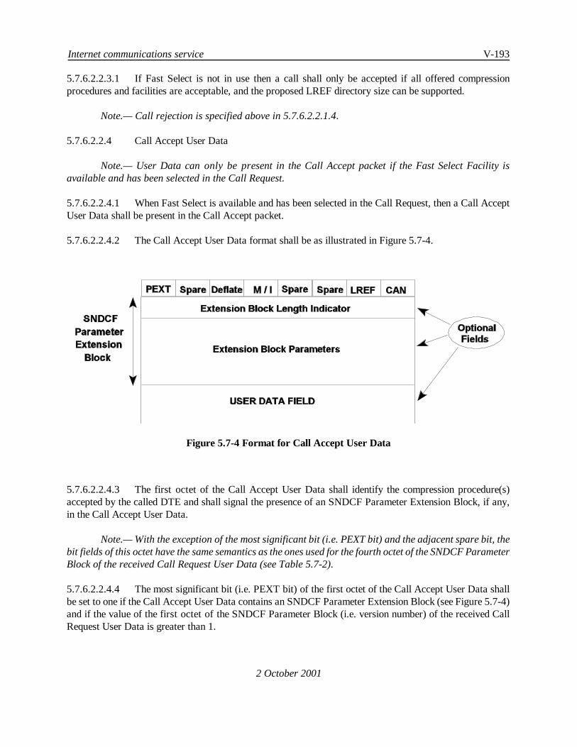
Internet communications service V-193
2 October 2001
Figure 5.7-4 Format for Call Accept User Data
5.7.6.2.2.3.1 If Fast Select is not in use then a call shall only be accepted if all offered compressionprocedures and facilities are acceptable, and the proposed LREF directory size can be supported.
Note.— Call rejection is specified above in 5.7.6.2.2.1.4.
5.7.6.2.2.4 Call Accept User Data
Note.— User Data can only be present in the Call Accept packet if the Fast Select Facility isavailable and has been selected in the Call Request.
5.7.6.2.2.4.1 When Fast Select is available and has been selected in the Call Request, then a Call AcceptUser Data shall be present in the Call Accept packet.
5.7.6.2.2.4.2 The Call Accept User Data format shall be as illustrated in Figure 5.7-4.
5.7.6.2.2.4.3 The first octet of the Call Accept User Data shall identify the compression procedure(s)accepted by the called DTE and shall signal the presence of an SNDCF Parameter Extension Block, if any,in the Call Accept User Data.
Note.— With the exception of the most significant bit (i.e. PEXT bit) and the adjacent spare bit, thebit fields of this octet have the same semantics as the ones used for the fourth octet of the SNDCF ParameterBlock of the received Call Request User Data (see Table 5.7-2).
5.7.6.2.2.4.4 The most significant bit (i.e. PEXT bit) of the first octet of the Call Accept User Data shallbe set to one if the Call Accept User Data contains an SNDCF Parameter Extension Block (see Figure 5.7-4)and if the value of the first octet of the SNDCF Parameter Block (i.e. version number) of the received CallRequest User Data is greater than 1.

V-194 Manual of Technical Provisions for the Aeronautical Telecommunication Network (ATN)
2 October 2001
Note.— The second conditionabove ensures backwards compatibility with ATN implementationswhich have signalled in the received Call Request packet to support Version 1 of the SNDCF protocol.
5.7.6.2.2.4.5 SNDCF Parameter Extension Block
Note.—The optional SNDCF Parameter Extension Block is used to convey to the calling SNDCFparameters related to the compression techniques which have been accepted by the called SNDCF.
5.7.6.2.2.4.5.1 If present, the SNDCF Parameter Extension Block shall start at the second octet of the CallAccept User Data.
5.7.6.2.2.4.5.2 The first octet of the SNDCF Parameter Extension Block is the length indicator of this blockand its value shall indicate the number of octets of the SNDCF Parameter Extension Block (including the lengthindicator field) as an unsigned binary number.
5.7.6.2.2.4.5.3 Each parameter contained within the SNDCF Parameter Extension Block shall be structuredas illustrated in Figure 5.7-3 and as specified in 5.7.6.2.1.5.5.4 through 5.7.6.2.1.5.5.6.
5.7.6.2.2.4.6 In case that the Call Accept Packet will be used to convey an NPDU, the octet following theSNDCF Parameter Extension Block, if such a block is present, or the second octet of the Call Accept User Datarespectively, if such a block is not present, shall be the first octet of this NPDU.
Note 1.— An ISO/IEC 9542 ISH PDU may be conveyed as part of the routing initiation procedure.
Note 2.— Since the negotiated compression procedures apply to the data transfer phase (see5.7.6.2.3.1), the optional NPDU in the Call Accept User Data, if present, is sent uncompressed.
5.7.6.2.2.4.7 Encoding of the Dictionary Selection Parameter
5.7.6.2.2.4.7.1 The Dictionary Selection Parameter shall be structured as illustrated in Figure 5.7-3.
5.7.6.2.2.4.7.2 The Parameter Code of the Dictionary Selection Parameter shall be set to [0000 0011].
5.7.6.2.2.4.7.3 The Parameter Length field of the Dictionary Selection Parameter shall be set to 2.
5.7.6.2.2.4.7.4 The Parameter Value field of the Dictionaries Selection Parameter shall consist of one andonly one Dictionary Tag as defined in 5.7.6.2.1.5.9.7, identifying the Data Stream Compression Dictionaryselected by the called DTE.
5.7.6.2.3 Data Transfer Phase
5.7.6.2.3.1 During thedata transfer phaseof a virtual circuit established by this SNDCF, the CompressionProcedures accepted by the called DTE shall be applied to each NPDU transferred over the virtual circuit.
Note.— NPDUs are queued for transfer as a result of an SN-UNITDATA.request. Received NPDUsare passed to the SN-Service user by an SN-UNITDATA.indication.

Internet communications service V-195
2 October 2001
5.7.6.2.3.2 The order in which concurrently applied Compression Procedures and ISO/IEC 8208segmentation are applied shall be as follows:
a) If the LREF compression algorithm is used, it shall be applied to the ISO/IEC 8473PDU first;
b) If the Deflate compression algorithm is used, it shall be applied after LREFcompression and before M-bit segmentation;
c) Finally, if the ISO/IEC 8208 M-bit sequencing procedures are required due to the sizeof the PDU, then these shall be applied.
5.7.6.2.3.3 This sequence shall be inverted on the receiving end as follows:
a) If M-bit -segmentation has been applied, then reassembly of the NPDU from thereceived ISO/IEC 8208 Data Packets shall bedone first;
b) If the Deflate compression algorithm is used the corresponding decompressionalgorithm shall be applied after M-bit segmentation and before LREF compression;
c) Finally if the LREF compression is used, the LREF decompression algorithm shallthen be applied.
5.7.6.2.4 Call Clearing
5.7.6.2.4.1 The SNDCF shall clear a virtual circuit:
a) When System Management requests call clearing, or
b) On the expiration of a timeout period following the transmission or receipt ofSN-UNITDATA, or
c) If the resources are required by another virtual circuit with a higher priority.
5.7.6.2.4.2 Items b) or c) above shall only apply to those virtual circuits that have been establishedfollowing an SN-UNITDATA.request.
5.7.6.2.4.3 When it has been determined that a virtual circuit is to be cleared, the SNDCF shall invokethe ISO/IEC 8208 functions associated with call clearing.
5.7.6.2.4.4 All packets subsequently received other than a Clear Confirm or a Clear Indication shall beignored.
5.7.6.2.4.5 The same actions shall apply to the receipt of a Clear Indication.

V-196 Manual of Technical Provisions for the Aeronautical Telecommunication Network (ATN)
2 October 2001
5.7.6.2.4.6 The Clearing Cause octet in the ISO/IEC-8208 Cause/Diagnostic field shall be set to [10000000].
5.7.6.2.4.7 The reason for clearing the call shall be placed in the Diagnostic field using the appropriatediagnostic values according to Table 5.7-4.
Note.— If a virtual connection is cleared due to a network problem, the SNDCF may attempt tore-establish the connection before the associated forwarding information is removed from Network Layerrouting tables. The selective re-establishment of X.25 connections may be based on the originating ClearingCause and Diagnostic Codes.
5.7.6.3 Local Reference Compression Procedures
5.7.6.3.1 Local Directory Initialization
5.7.6.3.1.1 Both calling and called SNDCFs shall create a local directory to be associated with each newlyestablished Subnetwork Connection Group.
5.7.6.3.1.2 This directory shall consist of entries numbered from zero to a maximum of 32767, each entryconsisting of:
a) A pair of NSAP Addresses, known as the inward and outward NSAP Addressesrespectively;
b) The ISO/IEC 8473 protocol version number;
c) The value of the security options parameter which may be empty.
5.7.6.3.1.3 The directory shall be initially empty. The Mobile SNDCF shall support a minimum directorysize of 128 entries.
Table 5.7-4 Diagnostic values for ATN call clearing
Binary value Decimal value Diagnostic Code
1 1111 1001 249 Connection Rejection - unrecognized protocolidentifier in user data
2 1000 0000 128 Version number not supported
3 1000 0001 129 Length field invalid
4 1000 0010 130 Call Collision Resolution
5 1000 0011 131 Proposed Directory Size too large
6 1000 0100 132 Local Reference Cancellation Not Supported

Internet communications service V-197
Binary value Decimal value Diagnostic Code
2 October 2001
7 1000 0101 133 Received DTE refused, received NET refused orinvalid NET selector
8 1000 0110 134 Invalid SNCR field
9 1000 0111 135 ACA compression not supportedNote.— Although the ACA is no longer
supported by this specification, this diagnostic code isretained for backwards compatibility reasons. It isused to reject incoming calls from implementationscompliant with previous versions of this specification,if they offer ACA without supporting the Fast SelectFacility.
10 1000 1000 136 LREF compression not supported
11 1000 1111 143 Deflate compression not supported
12 1111 0000 240 System lack of resources
13 0000 0000 0 Cleared by System Management
14 1001 0000 144 Idle Timer expiration
15 1001 0001 145 Need to re-use the circuit
16 1001 0010 146 By local means (to be used for system local error)
17 1001 0011 147 Invalid SEL field value in received NET
5.7.6.3.2 Action following an SN-UNITDATA Request
5.7.6.3.2.1 General
5.7.6.3.2.1.1 On receipt of a SN-UNITDATA request the SNDCF shall identify an appropriate virtualcircuit to the subnetwork user associated with the SN-Destination-Address, and which satisfies the PDUPriority and Security requirements, and queue the accompanying PDU (i.e. the user data associated with theSN-UNITDATA request) for transfer over that virtual circuit.
5.7.6.3.2.1.2 If there is no virtual circuit which satisfies the PDU Priority and Security requirement, thenthe SNDCF shall try to establish a virtual circuit with the requested PDU Security and priority.
5.7.6.3.2.1.3 If a suitable virtual circuit can be established, then the PDU shall be queued for transfer overthe newly established virtual circuit. If no such virtual circuit can be established, then if an existing virtualcircuit associated with theSN-Destination-Address provides an adequate level of security and priority, thePDUshall be queued for transfer over the existing virtual circuit.

V-198 Manual of Technical Provisions for the Aeronautical Telecommunication Network (ATN)
2 October 2001
5.7.6.3.2.1.4 Otherwise, the PDU shall be discarded.
Note 1.— The opening of an additional virtual circuit for this purpose may be inappropriate incertain cases. For example, opening an additional virtual circuit via a single frequency VDL subnetwork orvia the Mode S subnetwork will not necessarily result in increased capacity.
Note 2.— The maintenance of the minimum QoS level includes ensuring that the number of localreferences that are required to support the number of data streams multiplexed over a given virtual circuitdoes not exceed the number available.
5.7.6.3.2.1.5 If no virtual circuit exists to the SN-Destination-Address, and the circuit is not classified asdynamically assigned by the ISO/IEC10589 (IS-IS) routing protocol or under a static routing regime, then theSN-UNITDATA shall be discarded, with an error report sent to a System Manager.
Note.— Virtual Circuits between Intermediate Systems and between Intermediate Systems and EndSystems are initially established by procedures associated with the specific routing procedures employed.If no such virtual circuit has been established, or may be established under the routing procedures, then noroute exists and hence it is an error if an attempt is made to send a PDU over such a route.
5.7.6.3.2.2 Identification of Network Layer Protocol
5.7.6.3.2.2.1 Prior to transmission of an SN-UNITDATA SN-Userdata parameter over a virtual circuit, theSNDCF shall inspect the initial octet of the SN-Userdata parameter (Initial Protocol Identifier (IPI)) to identifythe Network Layer protocol contained within the SN-UNITDATA request.
5.7.6.3.2.2.2 If the IPI contains binary [1000 0001] indicating ISO/IEC8473, then the procedures in5.7.6.3.2.3 shall be performed.
5.7.6.3.2.2.3 If the IPI contains binary [1000 0010] indicating ISO/IEC 9542 (ES-IS), binary [1000 0011]indicating ISO/IEC 10589 (IS-IS), or binary [0100 0101] indicating ISO/IEC 11577 (NLSP), then the packetshall be sent unchanged over the virtual circuit, using the M-bit segmentation mechanism, if the packet is largerthan the maximum length of user data permitted for the virtual circuit.
5.7.6.3.2.2.4 If the IPI contains any other value, the SN-UNITDATA request shall be discarded, and anerror sent to a System Manager.
Note.— The IPI designating the ISO/IEC 11577 has been included in the set of allowed IPIs in orderto preserve the possiblity for use of this protocol in the future. However, at the time of publication of thisspecification, no ATN Security Protocol Architecture has been defined. Thus, this inclusion of the NLSP IPIin the allowed IPI set does not indicate that NLSP will be incorporated into the future ATN securityarchitecture.
5.7.6.3.2.3 Identification of Option Parameter and Local Directory Look-up
5.7.6.3.2.3.1 The ISO/IEC 8473 NPDU header contained in the SN-Userdata shall then be inspected. If oneof the following is true:

Internet communications service V-199
2 October 2001
a) the ISO/IEC 8473 NPDU is an Echo Request (ERQ) or Echo Response (ERP)NPDU,
b) parameters other than the security, priority or QoS maintenance parameters arepresent in the options part of the NPDU header,
c) the QoS Maintenance parameter is anything other than the globally unique format,
d) the priority option is present with a value greater than 14,
then the SN-Userdata shall be sent unchanged over the virtual circuit using M-bit segmentation procedures asappropriate.
5.7.6.3.2.3.2 Otherwise, the local directory associated with the virtual circuit shall then be interrogated todetermine if an entry exists such that:
a) the inward NSAP Address is equal to the PDU's source NSAP Address;
b) the outward NSAP Address is equal to the PDU's destination NSAP Address;
c) a security parameter is present with the same value as that contained in the PDUheader, if present, and otherwise absent;
d) the same ISO/IEC 8473 version number as is present in the PDU header.
5.7.6.3.2.3.3 If an entry is found, then the NPDU shall besent in thecompressed formconstructed accordingto 5.7.6.3.3, using the local directory entry number as the local reference.
5.7.6.3.2.3.4 If no entry is found, then a new directory entry shall be created and the SN-Userdata shall bemodified as specified in 5.7.6.3.2.4.
5.7.6.3.2.4 Establishing a New Local Reference
5.7.6.3.2.4.1 A new directory entry shall be created containing the NPDU source NSAP Address as theinward NSAP Address, and the NPDU destination NSAP Address as the outward NSAP Address.
5.7.6.3.2.4.2 The value of the protocol version number, and the security parameter, if present, shall also beplaced in this entry.
5.7.6.3.2.4.3 The entry number shall have the lowest possible entry number that has not previously beenused for the local directory associated with this virtual circuit, and shall be in the range [0..63] or [128..16447]if the SNDCF is the initiator of the first virtual circuit in a Subnetwork Connection Group, or [64..127] or[16448..32767], if the SNDCF is the responder for such a virtual circuit.

V-200 Manual of Technical Provisions for the Aeronautical Telecommunication Network (ATN)
2 October 2001
5.7.6.3.2.4.4 When a directory size greater than 128 but less than 32767 has been negotiated, then thehighest local reference that the initiator may allocate shall be
127 + (n -128) / 2
and the highest local reference that the responder may allocate shall be
16447 + (n -128) / 2
where 'n' is the agreed maximum directory size.
5.7.6.3.2.4.5 If a directory full condition occurs then, as a local matter, either the PDU shall be sentunmodified over the virtual circuit or the virtual circuit shall be reset.
Note.— A user generated Network Reset results in the total clearing of the directory which thenpermits the assignment of an unused local reference.
5.7.6.3.2.4.6 Recommendation.— When this SNDCF is used for Air/Ground communication or when thelocal reference cancellation option is available for use, then the PDU should be sent unmodified over thevirtual circuit.
5.7.6.3.2.4.7 The PDU, which may be either a DT PDU or an ER PDU, shall have an additional optionsfield added to the PDU header.
5.7.6.3.2.4.8 This option parameter shall have local significance only (i.e. is only of interest to the sendingand receiving SNDCFs), and is called the Local Reference.
5.7.6.3.2.4.9 This Local Reference option parameter shall be included as the first parameter in the OptionPart of the DT or ER PDU header.
5.7.6.3.2.4.10 This option shall be specified as follows:
Parameter Code: [0000 0101]
Parameter Length: variable
Parameter Value: the entry number of the local directory entrycreated above and expressed as an unsignedinteger.
Note 1.— The entry number is therefore assigned as a so called Local Reference.
Note 2.— The unsigned integer is encoded most significant byte first, in compliance with ISO/IEC8473-1.

Internet communications service V-201
2 October 2001
5.7.6.3.2.4.11 The Checksum, Length Indicator, and Segment Length fields of the PDU header shall bemodified to reflect the insertion of the new options field, and any changes to the length of the source anddestination address.
5.7.6.3.2.4.12 The Total Length, if present, shall be left unmodified.
5.7.6.3.2.5 Reference Cancellation Option
5.7.6.3.2.5.1 When the optional Local Reference Cancellation facility is implemented, and both SNDCFsusing a virtual circuit have indicated that they support this facility, then the SNDCF shall monitor the numberof local references on each virtual circuit which it has both assigned and are in use.
5.7.6.3.2.5.2 When the number of such local references on a given virtual circuit exceeds a SystemManagerspecified threshold, then the local reference cancellation procedures specified in 5.7.6.3.6 shall be invoked, inorder to ensure that the number of unused local references in the range in which the SNDCF is permitted toassign local references, is at least equal to a System Manager specified target.
5.7.6.3.2.6 Transfer of the Modified ISO/IEC 8473 PDU
5.7.6.3.2.6.1 The modified ISO/IEC 8473 NPDU (i.e. the NPDU with the added Local Reference Option)shall be inserted in the User Data field of an ISO/IEC 8208 Data packet and shall be sent over the virtualcircuit, using the ISO/IEC 8208 M-bit segmentation procedure if appropriate.
5.7.6.3.3 Compression of SN-Userdata
5.7.6.3.3.1 General
5.7.6.3.3.1.1 An Initial DT NPDU shall be compressed according to the procedures specified in 5.7.6.3.3.2.
5.7.6.3.3.1.2 A Derived DT NPDU shall becompressed according to theprocedures specified in 5.7.6.3.3.3.
5.7.6.3.3.1.3 An ER NPDU shall be compressed according to the procedures specified in 5.7.6.3.3.4.

V-202 Manual of Technical Provisions for the Aeronautical Telecommunication Network (ATN)
2 October 2001
Figure 5.7-5 Compressed Initial and Derived Formats
5.7.6.3.3.2 Initial DT PDU Compression
5.7.6.3.3.2.1 General
Note.— An Initial DT PDU is an ISO/IEC 8473 DT PDU that either contains no Segmentation Partin its PDU header or contains a Segmentation Part with a Segment Offset value that equals zero and theSegment Length is equal to the Total Length.
5.7.6.3.3.2.1.1 The original Initial DT PDU shall be compressed into the Compressed Initial Data PDU asshown in Figure 5.7-5.
5.7.6.3.3.2.1.2 The fields of the Compressed Initial Data PDU shall be set as follows.

Internet communications service V-203
2 October 2001
5.7.6.3.3.2.2 Type Field
5.7.6.3.3.2.2.1 The PDU Type field value shall be set according to the values of the original Initial DT PDUER, SP and More Segments (MS) flags as defined in Table 5.7-5.
Table 5.7-5 Initial DT PDU Type Codes
PDUType
Values
CLNPNPDU
ER Value
CLNPNPDU
SPValue
CLNPNPDU
MSValue
0 0 0 0 0 0 0
0 0 0 1 0 1 0
0 0 1 0 1 0 0
0 0 1 1 1 1 0
5.7.6.3.3.2.3 PDU Priority Field
5.7.6.3.3.2.3.1 The PDU Priority field value shall be set to the lowest four bits of the original PDU Priorityparameter value field, if the Priority option is present, and set to zero otherwise.
5.7.6.3.3.2.4 PDU Lifetime Field
5.7.6.3.3.2.4.1 The PDU Lifetime field value shall be set to the eight bits of the original NPDU lifetime field.
5.7.6.3.3.2.5 P bit Field
5.7.6.3.3.2.5.1 The P field value shall be set to one if the original uncompressed PDU contained the priorityoption. This field shall be set to zero otherwise.
5.7.6.3.3.2.6 Q bit Field
5.7.6.3.3.2.6.1 The Q field value shall be set to one if the original uncompressed PDU contained the QoSMaintenance option.
5.7.6.3.3.2.6.2 This field shall be set to zero otherwise.
5.7.6.3.3.2.7 R bit Field
5.7.6.3.3.2.7.1 The R field value shall be set to one if the original uncompressed PDU contains a non-zerochecksum.

V-204 Manual of Technical Provisions for the Aeronautical Telecommunication Network (ATN)
2 October 2001
5.7.6.3.3.2.7.2 This field shall be set to zero otherwise.
5.7.6.3.3.2.8 S/T, CE , T/C, E/T, and E/C Fields
5.7.6.3.3.2.8.1 The values of these fields shall be set to bits 5 through 1 of the QoS parameter value optionfield of the original PDU, if the Quality of Service maintenance option is present.
5.7.6.3.3.2.8.2 The S/T field shall be set to the value of bit 5 of the Quality of Service Maintenance parametervalue field, if present (i.e. sequencing vs. transit delay) and set to zero otherwise.
5.7.6.3.3.2.8.3 The CE field shall be set to the value of bit 4 in the Quality of Service Maintenance parametervalue field.
5.7.6.3.3.2.8.4 The T/C field shall be set to the value of bit 3 in the Quality of Service Maintenance parametervalue field.
5.7.6.3.3.2.8.5 The E/T field shall be set to the value of bit 2 in the Quality of Service Maintenance parametervalue field.
5.7.6.3.3.2.8.6 The E/C field shall be set to the value of bit 1 in the Quality of Service Maintenance parametervalue field.
5.7.6.3.3.2.9 EXP, Local-REF/A and Local-REF/B Fields
5.7.6.3.3.2.9.1 If the value of the Local Reference determined according to the procedure specified in5.7.6.3.2.4 is less than 128, then the EXP field shall be set to zero.
5.7.6.3.3.2.9.2 In this case, only the Local-REF/A field shall be present in the PDU.
5.7.6.3.3.2.9.3 The Local-REF/A field value shall be set to the value of the Local Reference encoded as anunsigned integer.
5.7.6.3.3.2.9.4 If the value of the Local Reference is greater than or equal to 128, the EXP field shall be setto one, and both Local-REF/A and Local-REF/B fields shall be present in the PDU.
5.7.6.3.3.2.9.5 The Local Reference shall be encoded as a 15 bit unsigned integer, with the least significanteight bits placed in the Local-REF/B field, and the most significant seven bits placed in the Local-REF/A field.
5.7.6.3.3.2.10 PDU Identifier
5.7.6.3.3.2.10.1 If the Initial DT PDU allows segmentation (SP Flag is set to one), then the PDUIdentifier field shall be included in the Compressed Initial Data PDU.
5.7.6.3.3.2.10.2 The PDU Identifier field shall contain the Data Unit Identifier as provided in thesegmentation part of the Initial DT PDU.

Internet communications service V-205
2 October 2001
5.7.6.3.3.2.10.3 If the Initial DT PDU does not allow segmentation (SP Flag is set to zero), then thisfield shall not be included in the Compressed Initial Data PDU.
5.7.6.3.3.2.11 PDU Segment Offset
5.7.6.3.3.2.11.1 This field shall not be present in the Compressed Data PDU for an Initial DT PDU.
Note.— The segment offset of an Initial DT PDU is always zero and is a priori known by thereceiving SNDCF.
5.7.6.3.3.2.12 PDU Total Length
5.7.6.3.3.2.12.1 This field shall not be present in the Compressed Data PDU for an Initial DT PDU.
Note.— The Total Length field value of an Initial DT PDU is the length of the entire PDU in octets.This value is identical to the value of the Segment Length field for an Initial DT PDU and both values maybe recalculated by the receiving SNDCF.
5.7.6.3.3.2.13 Network Service Data Unit Field
5.7.6.3.3.2.13.1 This field shall contain the Data Part of the original Initial DT PDU.
5.7.6.3.3.3 Derived DT PDU Compression
5.7.6.3.3.3.1 General
5.7.6.3.3.3.1.1 The original Derived DT PDU shall be compressed into the Compressed Derived Data PDUas shown in Figure 5.7-5.
5.7.6.3.3.3.1.2 The fields of the Compressed Derived Data PDU shall be set as defined in the followingsections.
5.7.6.3.3.3.2 Type Field
5.7.6.3.3.3.2.1 The PDU Type field value shall be set according to the values of the original NPDU ER, SPand MS flags as defined in Table 5.7-6.
Table 5.7-6 Derived PDU Type Codes
PDU Type Values CLNP NPDU ER Value CLNP NPDU SP Value CLNP NPDU MSValue
0 1 1 0 0 1 0
0 1 1 1 0 1 1
1 0 0 1 1 1 0

V-206 Manual of Technical Provisions for the Aeronautical Telecommunication Network (ATN)
PDU Type Values CLNP NPDU ER Value CLNP NPDU SP Value CLNP NPDU MSValue
2 October 2001
1 0 1 0 1 1 1
5.7.6.3.3.3.3 PDU Priority Field
5.7.6.3.3.3.3.1 This field shall be set as defined in 5.7.6.3.3.2.3.
5.7.6.3.3.3.4 PDU Lifetime Field
5.7.6.3.3.3.4.1 This field shall be set as defined in 5.7.6.3.3.2.4.
5.7.6.3.3.3.5 P bit Field
5.7.6.3.3.3.5.1 This field shall be set as defined in 5.7.6.3.3.2.5.
5.7.6.3.3.3.6 Q bit Field
5.7.6.3.3.3.6.1 This field shall be set as defined in 5.7.6.3.3.2.6.
5.7.6.3.3.3.7 S/T, CE , T/C, E/T, and E/C Fields
5.7.6.3.3.3.7.1 These fields shall be set as defined in 5.7.6.3.3.2.8.
5.7.6.3.3.3.8 EXP, Local-REF/A and Local-REF/B Fields
5.7.6.3.3.3.8.1 These fields shall be set as defined in 5.7.6.3.3.2.9.
5.7.6.3.3.3.9 PDU Identifier Field
5.7.6.3.3.3.9.1 The PDU Identifier field value shall be set to the Data Unit Identifier contained in thesegmentation part of the original Derived DT PDU header.
5.7.6.3.3.3.10 PDU Segment Offset Field
5.7.6.3.3.3.10.1 ThePDU Segment Offset field valueshall beset to theSegment Offset valuecontainedin the segmentation part of the original Derived DT PDU header.
5.7.6.3.3.3.11 PDU Total Length Field
5.7.6.3.3.3.11.1 The PDU Total Length field value shall be set to the value of the Total Length fieldcontained in the Segmentation Part of the original Derived DT PDU.
5.7.6.3.3.4 Error Report PDU Compression
Internet communications service V-207
2 October 2001
5.7.6.3.3.4.1 General
5.7.6.3.3.4.1.1 The original ER PDU shall be compressed into the Compressed Error Report PDU as shownin Figure 5.7-6.
5.7.6.3.3.4.1.2 The fields of the Compressed Error Report PDU shall be set as defined in the followingsections.
5.7.6.3.3.4.2 PDU Type Field
5.7.6.3.3.4.2.1 The PDU Type field value shall be set to [1101].
5.7.6.3.3.4.3 PDU Priority Field
5.7.6.3.3.4.3.1 This field shall be set as defined in 5.7.6.3.3.2.3.
5.7.6.3.3.4.4 PDU Lifetime Field
5.7.6.3.3.4.4.1 This field shall be set as defined in 5.7.6.3.3.2.4.
5.7.6.3.3.4.5 P bit Field
5.7.6.3.3.4.5.1 This field shall be as defined in 5.7.6.3.3.2.5.
5.7.6.3.3.4.6 Q bit Field
5.7.6.3.3.4.6.1 This field shall be set as defined in 5.7.6.3.3.2.6.
5.7.6.3.3.4.7 S/T, CE , T/C, E/T and E/C Fields
5.7.6.3.3.4.7.1 These fields shall be set as defined in 5.7.6.3.3.2.8.
5.7.6.3.3.4.8 EXP, Local-REF/A, Local-REF/B Fields
5.7.6.3.3.4.8.1 These fields shall be set as defined in 5.7.6.3.3.2.9.
5.7.6.3.3.4.9 Discard Reason Field
5.7.6.3.3.4.9.1 This field shall be set to the value of the Reason for Discard Parameter Value field containedin the original NPDU header.
5.7.6.3.3.4.10 Header of Discarded NPDU Field
5.7.6.3.3.4.10.1 This field shall contain the value of the Error Report Data Part if provided in theoriginal Error Report PDU.

V-208 Manual of Technical Provisions for the Aeronautical Telecommunication Network (ATN)
2 October 2001
Compressed Error Report PDU
CE:
T/C:
E/T:
E/C: "Error Probability over Cost" Flag
"Error Probability over Transit Delay" Flag
"Transit Delay over Cost" Flag
"Congestion Experienced" Flag
EXP: "Local-REF Extension" Flag
S/T: "Sequencing over Transit Delay" Flag
OptionalFields
EXP
P Q R S/T CE T/C E/T E/C
PDU Lifetime
PDU Type PDU Priority
Local-REF/A
Local-REF/B
Discard Reason
Headerof
DiscardedNPDU
5Octets
2 Octets
HOctets
Figure 5.7-65 Compressed Error Report PDU |
5.7.6.3.3.4.11 Transfer of Compressed ISO/IEC 8473 PDUs
5.7.6.3.3.4.11.1 The compressed ISO/IEC 8473 NPDU (i.e. Compressed Initial Data PDU,Compressed Derived Data PDU, or Compressed Error Report PDU) shall be inserted in the User Data fieldof an ISO/IEC 8208 Data packet and shall be sent over the virtual circuit, using the ISO/IEC 8208 M-bitsegmentation procedure if appropriate.
5.7.6.3.4 Processing of Packets Received from the Subnetwork Service Provider
Note.— The following sections specify the processing of packets received from the SubnetworkService provider.
5.7.6.3.4.1 Initial Processing of NPDU
5.7.6.3.4.1.1 On receipt of an incoming packet received from a virtual circuit, the SNDCF shall inspect thefirst octet to determine the Network Layer Protocol ID or the compressed PDU type (see Table 5.7-7).
a) If this value is set to[1000 0001]indicating that the NPDU is an ISO/IEC 8473NPDU with an uncompressed header, then the NPDU shall be processed accordingto 5.7.6.3.4.2.2.

Internet communications service V-209
2 October 2001
b) If the first octet indicates either ISO/IEC 9542 (ES-IS), ISO/IEC 11577 (NLSP) orISO/IEC 10589 (IS-IS), the SNDCF shall generate an SN-UNITDATA.indicationwith the NPDU as its SN-Userdata parameter, and the SN-Source-Address andSN-Destination-Address parameters set to the remote and local DTE addresses forthe virtual circuit over which the NPDU was received.
c) If the value of the first four bits of the first octet is in the range binary[0000] tobinary [0011] then the PDU is a compressed ISO/IEC 8473 Initial DT PDU whichshall be decompressed using the procedures specified in 5.7.6.3.4.3.
d) If the value of the first four bits of the first octet is in the range binary[0110] tobinary[1010](excluding 1000) then the PDU is a compressed ISO/IEC 8473 DerivedPDU, which shall be decompressed using the procedures specified in 5.7.6.3.4.3.
e) If the value of the first four bits of the first octet is binary[1101] then the PDU is acompressed ISO/IEC 8473 Error PDU, which shall be decompressed using theprocedures specified in 5.7.6.3.4.4.
f) If the value of the first four bits of the first octet is binary[1110] then the PDU is anSNDCF Error Report, which shall be processed according to the procedures of5.7.6.3.4.5, and no SN-UNITDATA.indication generated.
g) If the value of the first four bits of the first octet is binary[0100] or binary[0101],then the PDU is respectively, a local reference cancellation request or response, whichshall be processed according to the procedures of 5.7.6.3.6 and noSN-UNITDATA.indication generated.
Table 5.7-7 Mapping between Compressed PDU Type Fields and Uncompressed PDU Types
Compressed PDUType Field
Uncompressed PDU Type
[0000] - [ 0011] Compressed Initial DT PDU
[0110] - [0111][1001] - [1010]
Compressed Derived DTPDU
[1101] Compressed Error ReportPDU
[1110] SNDCF Error Report
[0100] Cancellation Request PDU
[0101] Cancellation Accept PDU
5.7.6.3.4.1.2 In all other cases, the PDU shall be discarded and an SNDCF Error Report Generated (see5.7.6.3.5).

V-210 Manual of Technical Provisions for the Aeronautical Telecommunication Network (ATN)
2 October 2001
5.7.6.3.4.2 Incoming ISO/IEC 8473 PDU with Uncompressed Header
5.7.6.3.4.2.1 General
5.7.6.3.4.2.1.1 If the received NPDU is an ISO/IEC 8473 NPDU then the options part shall be inspected forthe options field containing the local reference.
5.7.6.3.4.2.2 Processing of Unmodified ISO/IEC 8473 PDUs
5.7.6.3.4.2.2.1 If the local reference option is not present, then the SNDCF shall generate a SN-UNITDATAindication with the NPDU as its SN-Userdata, and the SN-Source-Address and SN-Destination-Addressparameters set to the remote and local DTE addresses for the virtual circuit over which the NPDU wasreceived.
5.7.6.3.4.2.3 Processing of Modified ISO/IEC 8473 PDUs
5.7.6.3.4.2.3.1 If the Local Reference option is present, it shall be removed, and the checksum and PDUheader length indication and segment length shall be modified to reflect this removal.
5.7.6.3.4.2.3.2 If a Local Reference options field is present, then the local directory associated with the virtualcircuit over which the PDU was received shall be inspected for the presence of the corresponding entry.
5.7.6.3.4.2.3.3 If no such entry is present, and the value of the Local Reference is in the range within whichthe remote SNDCF is permitted to create local directory entries, then the entry shall be created, and:
a) The value of the inward NSAP Address set to the PDU's destination NSAP Address,
b) The value of the outward NSAP Address set to the NSAP's source NSAP Address,and
c) The values of the Version Number and Security Parameter, set to the correspondingvalues in the PDU header.
5.7.6.3.4.2.3.4 An SNDCF Error Report (see 5.7.6.3.5) shall be generated if the value of the Local Referenceis not within the range within which the remote SNDCF is permitted to create local directory entries, or isgreater than the maximum negotiated when the call was established.
5.7.6.3.4.2.3.5 Otherwise, the local directory entry shall be compared with the received PDU. If:
a) The inward NSAP Address does not match the destination NSAP Address, or
b) The outward NSAP Address does not match the source NSAP Address, or
c) The Version Number does not match the Version Number present in the directoryentry, or

Internet communications service V-211
2 October 2001
d) The value of the Security options parameter does not match the value in the directory,or is not correspondingly absent, then
an SNDCF Error Report shall be generated and returned over the same virtual circuit as the PDU was received.
5.7.6.3.4.2.3.6 The SNDCF shall then generate a SN-UNITDATA.indication with the NPDU as itsSN-Userdata, and the SN-Source-Address and SN-Destination-Address parameters set to the remote and localDTE addresses for the virtual circuit over which the NPDU was received.
5.7.6.3.4.3 Incoming Compressed Data PDU
5.7.6.3.4.3.1 General
5.7.6.3.4.3.1.1 If the most significant four bits of the first octet of a received PDU (i.e. the PDU Type field)are in the range [0000] to [0011] binary, excluding [1000], then the packet is a compressed ISO/IEC 8473Initial DT NPDU.
5.7.6.3.4.3.1.2 If the PDU Type field of a received compressed PDU is in the range [0110] to [1010] binary,then the PDU is a compressed ISO/IEC 8473 Derived DT NPDU.
5.7.6.3.4.3.1.3 Upon receipt, the SNDCF shall examine and validate the Local-REF in the compressed PDU.
5.7.6.3.4.3.1.4 The value of the Local Reference shall be extracted from the compressed header and thecorresponding entry in the local directory located.
5.7.6.3.4.3.1.5 If no entry exists corresponding to the Local-REF present in the PDU, then an SNDCF ErrorReport shall be generated and returned over the same virtual circuit as the PDU was received, and the PDUshall be discarded.
5.7.6.3.4.3.1.6 If the Local-REF is valid, the original uncompressed NPDU shall be recreated by theprocedures defined in 5.7.6.3.4.3.2 through 5.7.6.3.4.3.6.
5.7.6.3.4.3.1.7 The SNDCF then shall generate a SN-UNITDATA.indication with the SN-Source Addressand SN-Destination Address parameters set to the remote and local DTE addresses for the virtual circuit overwhich the NPDU was received, and the SN-Userdata shall be set to the uncompressed DT NPDU.
5.7.6.3.4.3.2 Fixed Part
Note 1.— The Fixed Part of the NPDU header consists of the Network Layer Protocol Identifier,Length Indicator, Version/Protocol Identifier Extension, PDU Lifetime, SP flag, MS flag, E/R Flag, Type,Segment Length and Checksum fields as defined in ISO/IEC 8473.
Note 2.— If the EXP field is set to zero, the Local Reference is the seven bit integer value of theLocal-REF/A field. If the EXP field is set to one, the Local Reference value consists of the fifteen bit unsignedinteger as stored with the least significant eight bits placed in the Local-REF/B field, and the most significantseven bits placed in the Local-REF/A field.

V-212 Manual of Technical Provisions for the Aeronautical Telecommunication Network (ATN)
2 October 2001
5.7.6.3.4.3.2.1 Network Layer Protocol Identifier
5.7.6.3.4.3.2.1.1 This field shall be set to binary [1000 0001] to identify this Network Layer Protocol asISO/IEC 8473.
5.7.6.3.4.3.2.2 Length Indicator
5.7.6.3.4.3.2.2.1 This field shall be set to the length of the uncompressed NPDU header in octets.
5.7.6.3.4.3.2.3 Version/Protocol Identifier Extension
5.7.6.3.4.3.2.3.1 The Version/Protocol Identifier Extension field shall be set to the values provided in thecorresponding entry of the local directory.
5.7.6.3.4.3.2.4 PDU Lifetime
5.7.6.3.4.3.2.4.1 The eight bits of the PDU Lifetime field shall be set to the eight bits of the PDU Lifetimefield of the Compressed Data PDU.
5.7.6.3.4.3.2.5 Segmentation Permitted, More Segments, Error Report Flags
5.7.6.3.4.3.2.5.1 The values of these flags shall be derived from the value of the Protocol ID field and Typefield of the Compressed Data PDU.
5.7.6.3.4.3.2.5.2 These flag values shall be determined according to Table 5.7-5 for an Initial Data PDU andTable 5.7-6 for a Derived Data PDU.
5.7.6.3.4.3.2.6 Type Code
5.7.6.3.4.3.2.6.1 This field shall be set to binary [11100] to indicate a DT PDU.
5.7.6.3.4.3.2.7 Segment Length
5.7.6.3.4.3.2.7.1 This field shall indicate the entire length in octets of the PDU, including both header anddata.
5.7.6.3.4.3.2.7.2 The value of this field shall be computed by the SNDCF.
5.7.6.3.4.3.2.7.3 For an Initial DT NPDU, the value of this field shall be identical to the value of the TotalLength field located in the Segmentation Part of the header.
5.7.6.3.4.3.2.8 PDU Checksum
5.7.6.3.4.3.2.8.1 The value of this field shall be set to zero if the R bit in the compressed header is zero.
5.7.6.3.4.3.2.8.2 Otherwise, a Checksum field shall be recomputed.

Internet communications service V-213
2 October 2001
Note.— For the DT PDU, this includes the segmentation and options part (if present). For the ErrorReport PDU, this includes the reason for discard field as well.
5.7.6.3.4.3.3 Address Part
Note.— The Address Part consists of the Destination Address Length Indicator, Destination Address,Source Address Length Indicator and Source Address as defined in ISO/IEC 8473.
5.7.6.3.4.3.3.1 Destination and Source Address Length Indicators and Addresses
5.7.6.3.4.3.3.1.1 The Source and Destination NSAP addresses shall be set to the values provided in thecorresponding entry of the local directory for the Local Reference number calculated.
5.7.6.3.4.3.3.1.2 The source NSAP Address shall be set to the value of the outward NSAP Address, and thedestination NSAP Address set to the value of the inward NSAP Address.
5.7.6.3.4.3.3.1.3 The Length fields shall contain the length of each address in octets.
5.7.6.3.4.3.4 Segmentation Part
5.7.6.3.4.3.4.1 General
5.7.6.3.4.3.4.1.1 If the ISO/IEC 8473 SP field is set to one, then the Segmentation Part shall be generated.
5.7.6.3.4.3.4.1.2 The Segmentation Part shall consist of the Data Unit Identifier, Segment Offset, and TotalLength field as defined in ISO/IEC 8473.
5.7.6.3.4.3.4.2 Data Unit Identifier
5.7.6.3.4.3.4.2.1 This field shall contain the value of the PDU Identifier field as provided in the compressedDT PDU.
5.7.6.3.4.3.4.3 Segment Offset
5.7.6.3.4.3.4.3.1 For an Initial DT PDU, this field shall be set to zero.
5.7.6.3.4.3.4.3.2 For a Derived DT PDU, this field shall be set to the PDU Segment Offset field as providedin the compressed DT PDU.
5.7.6.3.4.3.4.4 PDU Total Length
5.7.6.3.4.3.4.4.1 For a Derived DT PDU, this field shall contain the value of the PDU Total Length field asprovided in the Compressed DT PDU.
5.7.6.3.4.3.4.4.2 For an Initial PDU, the entire length of the PDU in octets shall be calculated by the SNDCFand stored in this field.
V-214 Manual of Technical Provisions for the Aeronautical Telecommunication Network (ATN)
2 October 2001
5.7.6.3.4.3.5 Options Part
5.7.6.3.4.3.5.1 General
5.7.6.3.4.3.5.1.1 If the Q bit field is set to one, the Globally Unique QoS option shall be recreated accordingto 5.7.6.3.4.3.5.3.
5.7.6.3.4.3.5.1.2 If the Security option is present in the local referencedirectory entry, the Security option shallbe recreated according to 5.7.6.3.4.3.5.4.
5.7.6.3.4.3.5.1.3 If the P bit field is set to one, the Priority option shall be recreated according to5.7.6.3.4.3.5.2.
5.7.6.3.4.3.5.2 Priority
5.7.6.3.4.3.5.2.1 For the Priority option, the Parameter Code shall be set to binary [1100 1101] and theParameter Length set to one octet.
5.7.6.3.4.3.5.2.2 The four most significant bits of the Parameter Value shall be set to zero, and the four leastsignificant bits set to the PDU Priority field as provided in the compressed DT PDU.
5.7.6.3.4.3.5.3 Quality of Service Maintenance
5.7.6.3.4.3.5.3.1 For the Quality of Service Maintenance option, the Parameter Code shall be set to binary[1100 0011], the Parameter Length set to one octet.
5.7.6.3.4.3.5.3.2 The high order two bits of the Parameter Value shall be set to binary [11] to indicate GloballyUnique, bit 6 shall be set to zero, and bits 5 through one set to the S/T, CE , T/C, E/T and E/C fieldsrespectively as provided in the compressed Data PDU.
5.7.6.3.4.3.5.4 Security
5.7.6.3.4.3.5.4.1 This field shall be set to the value of the Security parameter contained in the correspondingLocal Reference directory entry.
5.7.6.3.4.3.6 Data Part
5.7.6.3.4.3.6.1 The Data Part shall be copied from the Compressed Data PDU data part.
5.7.6.3.4.4 Incoming Compressed Error Report PDU
5.7.6.3.4.4.1 General
5.7.6.3.4.4.1.1 The original uncompressed header shall be recreated as defined in the following sections.

Internet communications service V-215
2 October 2001
Note.— If the four most significant bits of the first octet (the PDU Type Field) of a received packetare [1101] then the packet is a compressed ISO/IEC 8473 ER NPDU.
5.7.6.3.4.4.2 Fixed Part
5.7.6.3.4.4.2.1 The Fixed Part of the ER PDU shall be composed in the same manner as defined in5.7.6.3.4.3.2 except for the Type Code which shall be set to binary [00001] to indicate an ER PDU, and forthe SP and MS flags which shall be set to zeros.
5.7.6.3.4.4.3 Address Part
5.7.6.3.4.4.3.1 The Address Part of the ER PDU shall be composed in the same manner as defined in5.7.6.3.4.3.3.
5.7.6.3.4.4.4 Options Part
5.7.6.3.4.4.4.1 The Options Part of the ER PDU shall be composed in the same manner as defined in5.7.6.3.4.3.5 for an Initial DT PDU.
5.7.6.3.4.4.5 Reason for Discard
5.7.6.3.4.4.5.1 To compose this field, the Parameter Code shall be set to binary [1100 0001], the ParameterLength set to two octets, and the Parameter Value set to the Discard Reason field as provided in theCompressed Error Report PDU.
5.7.6.3.4.4.6 Error Report Data Part
5.7.6.3.4.4.6.1 If the Compressed Error Report PDU contains the Header of Discarded NPDU field, then theError Report Data Part shall be set to the value of the Header of Discarded NPDU field.
5.7.6.3.4.5 Incoming SNDCF Error Report
5.7.6.3.4.5.1 On receipt of an SNDCF Error Report with reason “compressed NPDU with unrecognizedlocal reference”, the directory entry corresponding to the local reference returned in the SNDCF Error Reportshall be reset to the unused state.
5.7.6.3.4.5.2 On receipt of an SNDCF Error Report with reason other than “compressed NPDU withunrecognized local reference” (see Table 5.7-8), the virtual circuit shall be reset (see 5.7.6.3.7) and the localreference directory associated with the virtual circuit shall be cleared to its initial state.
Note.— If the virtual circuit on which the error has been reported belongs to a connection groupwhich shares the same LREF directory, there is no need to reset the remaining virtual circuits of that group.
5.7.6.3.4.5.3 Recommendation.— The error should be notified to Systems Management.
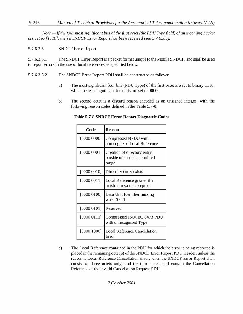
V-216 Manual of Technical Provisions for the Aeronautical Telecommunication Network (ATN)
2 October 2001
Note.— If the four most significant bits of the first octet (the PDU Type field) of an incoming packetare set to [1110], then a SNDCF Error Report has been received (see 5.7.6.3.5).
5.7.6.3.5 SNDCF Error Report
5.7.6.3.5.1 The SNDCF Error Report is a packet format unique to the Mobile SNDCF, and shall be usedto report errors in the use of local references as specified below.
5.7.6.3.5.2 The SNDCF Error Report PDU shall be constructed as follows:
a) The most significant four bits (PDU Type) of the first octet are set to binary 1110,while the least significant four bits are set to 0000.
b) The second octet is a discard reason encoded as an unsigned integer, with thefollowing reason codes defined in the Table 5.7-8:
Table 5.7-8 SNDCF Error Report Diagnostic Codes
Code Reason
[0000 0000] Compressed NPDU withunrecognized Local Reference
[0000 0001] Creation of directory entryoutside of sender's permittedrange
[0000 0010] Directory entry exists
[0000 0011] Local Reference greater thanmaximum value accepted
[0000 0100] Data Unit Identifier missingwhen SP=1
[0000 0101] Reserved
[0000 0111] Compressed ISO/IEC 8473 PDUwith unrecognized Type
[0000 1000] Local Reference CancellationError
c) The Local Reference contained in the PDU for which the error is being reported isplaced in the remaining octet(s) of the SNDCF Error Report PDU Header, unless thereason is Local Reference Cancellation Error, when the SNDCF Error Report shallconsist of three octets only, and the third octet shall contain the CancellationReference of the invalid Cancellation Request PDU.
Internet communications service V-217
2 October 2001
5.7.6.3.5.3 The data portion of the SNDCF Error Report shall be used to return a copy of the PDU inerror, similar to the ISO/IEC 8473 Error Report PDU.
5.7.6.3.5.4 The Error Report PDU shall be sent as an ISO/IEC 8208 DATA packet(s) and, if needed,segmented using the M-bit procedures.
5.7.6.3.6 Local Reference Cancellation Option
5.7.6.3.6.1 General
Note.— When the implementation of this option has been agreed by both SNDCFs using a virtualcircuit during the call setup procedures, then the following procedures may be used to selectively cancel oneor more Local References, i.e. make them available for re-use. An SNDCF may only request the cancellationof Local References which are within the range in which it is permitted to assign Local References.
5.7.6.3.6.1.1 When an SNDCF invokes the procedures for Local Reference cancellation it shall format aCancellation Request PDU, as specified below, and send the PDU to the other SNDCF over the virtual circuitto which it applies.
5.7.6.3.6.1.2 A Cancellation Request PDU shall be retransmitted periodically until it is acknowledged bya cancellation accept PDU, or an SNDCF Error Report PDU is received indicating an error in the request.
5.7.6.3.6.1.3 When a Cancellation Accept PDU is received, the corresponding directory entries shall becleared, and the Local References therefore become available for re-use.
5.7.6.3.6.1.4 When an SNDCF receives a Cancellation Request PDU, it shall first check to ensure that thelocal references identified in the PDU are within the range in which the sending SNDCF is permitted to assignlocal references.
5.7.6.3.6.1.5 If any one of them is not, then an SNDCF error report shall be returned, and the requestignored.
5.7.6.3.6.1.6 Otherwise, the directory entries corresponding to the indicated local references shall becleared, and a cancellation accept PDU be formatted and returned, in order to accept cancellation of these localreferences.
5.7.6.3.6.2 The Cancellation Request PDU
5.7.6.3.6.2.1 The PDU format shall be as illustrated in Figure 5.7-7. The first octet shall be set to [01000000]. The remainder of the PDU shall consist of:
a) A Cancellation Reference expressed as a one octet unsigned integer, and whichuniquely identifies this Cancellation Request within the context of the virtual circuit.
Note.— In most cases uniqueness will be assured if the reference is implemented as a sequencenumber starting at zero and incremented by one (modulo 256), each time a Cancellation Request is sent.

V-218 Manual of Technical Provisions for the Aeronautical Telecommunication Network (ATN)
2 October 2001
PDU Type Unused
Cancellation Reference
L1
EXP Local-REF/A
Local-REF/B
.
.
.
L2
EXP Local-REF/A
Local-REF/B
.
.
.
Figure 5.7-7 Cancellation Request PDU
b) A length octet (L1) given as an unsigned integer (0 to 255), which indicates the lengthin octets of the set of individual Local References to cancel.
c) One or more Local References expressed as one or two octets each, as appropriate,and encoded in successive octets, with the total number of octets containing such localreferences given by L1.
d) A length octet (L2) given as an unsigned integer (0 to 255), which indicates the lengthin octets of the set of inclusive Local Reference ranges to cancel.
e) One or more pairs of Local Reference ranges expressed as one or two octets each, asappropriate, and encoded in successive octets, with the total number of octetscontaining such Local References given by L2.

Internet communications service V-219
2 October 2001
PDU Type Unused
Cancellation Reference
Figure 5.7-8 Cancellation Accept PDU |
5.7.6.3.6.2.2 In each of the above cases, if the value of a local reference is less than 128, then bit eight ofthe first octet in which it is encoded shall be set to zero, and the remaining seven bits set to the value of theLocal Reference encoded as an unsigned integer.
5.7.6.3.6.2.3 The extended Local Reference octet shall not be present.
5.7.6.3.6.2.4 Otherwise, bit eight shall be set to one, and the remaining seven bits and the next octet set tothe value of the Local Reference encoded as a 15 bit unsigned integer, with the least significant eight bits placedin the extended Local Reference octet, and the most significant seven bits placed in the first octet.
Note.— This format allows for the Local References to be cancelled, to be expressed as either a setof individual references, or a set of inclusive ranges of individual references, or both.
5.7.6.3.6.3 The Cancellation Accept PDU
5.7.6.3.6.3.1 The PDU format shall be as illustrated in Figure 5.7-8.
5.7.6.3.6.3.2 The first octet shall be set to binary [0101 0000], and the second octet set to the CancellationReference of the Cancellation Request which is being accepted.
5.7.6.3.7 Call Reset Provisions
5.7.6.3.7.1 If at any time, a Reset Indication is received indicating a DCE originated reset, then this shallbe confirmed and all other procedures associated with the Call Reset performed.
Note.— There is otherwise no impact on this SNDCF.
5.7.6.3.7.2 If the Reset Indication indicates a DTE user originated reset then, additionally, the directoryassociated with the virtual circuit shall be cleared to its initial state.
5.7.6.3.8 Call Clearing and LREF Procedures
5.7.6.3.8.1 When a virtual circuit has been terminated and the corresponding Subnetwork ConnectionGroup is now empty, then the Local Reference Directory associated with this group shall be discarded.

V-220 Manual of Technical Provisions for the Aeronautical Telecommunication Network (ATN)
2 October 2001
5.7.6.4 Paragraph has been deleted.
5.7.6.5 Stream Mode Compression Using Deflate
Note 1.— The Deflate algorithm was originally specified in IETF RFC 1951 and through example‘C’ code available from the algorithm’s authors.
Note 2.— The Deflate algorithm is a combination of two public domain and well known datacompression algorithms. These are the LZ77 algorithm (Lempel-Ziv 1977) and Huffman Codes. LZ77removes redundancy in the data stream by replacing re-occurring strings by backward references to previousoccurrences of such strings. Huffman Codes are variable length symbols that are used to compress stringsof fixed length symbols. The Huffman Codes are chosen such that frequently occurring symbols are replacedby shorter bitstrings whilst rarely occurring symbols are replaced by longer bitstrings. They are also chosensuch that no code is the prefix of another code in the same set of Huffman Codes. In Deflate, theuncompressed data is first compressed using LZ77 and the result of this compression stage is furthercompressed using a set of standard Huffman Codes in order to compress both the literal value of strings forwhich no backward reference can be given, and the backward references themselves.
Note 3.— Deflate further optimises the data compression by monitoring the stream of uncompresseddata and dynamically generating a set of more optimal Huffman Codes. These can be communicated to thereceiver at any time and used to improve the compression ratio.
Note 4.— The Deflate specification also permits the compressor, when it detects an uncompressiblestring, to send that string as plain text.
Note 5.— The Deflate algorithm has significant memory requirements when providing highcompression efficiency. This extensive memory demand per compressed data stream may limit the numberof virtual circuits which can be simultaneously supported by a given ATN Router implementation over anair/ground adjacency. Consequently, ATN operators may choose to not support data stream compressionwhen the demand for simultaneous air/ground connections exceeds the available memory resources.
5.7.6.5.1 Service Description
Note.— The Deflate encoder operates on NPDUs submitted via theSN-Service and after compressionby the LREF function if used. The Deflate decoder operates on data packets received from the subnetworkservice provided by ISO/IEC 8208. The decoded NPDUs may then be further decompressed by the LREFcompression procedures, if in use, or passed to the SN-Service user. The positioning of the Deflate encoderand decoder is illustrated in Figure 5.7-9.

Internet communications service V-221
2 October 2001
Figure 5.7-9 Relationship of the Deflate Encoder and Decoder toISO/IEC 8208 and LREF Functions
5.7.6.5.1.1 When the use of the Deflate algorithm has been proposed in the Call Request User Data andeither implicitly accepted by Call Acceptance in the absence of the Fast Select procedures, or explicitlyaccepted in the Call Accept when Fast Select is in use, then user data on all subsequent data packets shall beencoded using this algorithm.
Note.— ISO/IEC 8208 packets other than data packets may also contain user data. The aboverequirement excludes the encoding of user data on control packets as they may be delivered out of sequence.
5.7.6.5.2 Encoded Packet Format
5.7.6.5.2.1 Each NPDU shall be encoded into the compressed representation shown in Figure 5.7-10.
Encoded Data FCS
Figure 5.7-10 Compressed Packet Format
5.7.6.5.2.2 The compressed packet format shall comprise:
a) The Encoded Data, and
b) A two-octet Frame Check Sum (FCS).

V-222 Manual of Technical Provisions for the Aeronautical Telecommunication Network (ATN)
2 October 2001
Note.— The length of the encoded data need not be explicitly specified as the encoded block isdelimited by ISO/IEC 8208.
5.7.6.5.2.3 The sender shall ensure that the encoded representation of an NPDU is complete, i.e. that thereceiver can recover the original NPDU without requiring information contained in any subsequent packets.
Note.— In IETF RFC 1951, an encoded data stream may comprise an arbitrary number ofcompressed blocks. This is also true for this specification. The purpose of the Deflate Data Blocks is todelimit the scope of uncompressed data strings, strings compressed using the standard set of Huffman Codes,and those compressed using dynamically determined Huffman Codes. The compressor may decide to changebetween either one of these strategies at any time and not just at an NPDU boundary.
5.7.6.5.2.4 The encoded representation of the NPDUs shall be a data stream that is subdivided into anumber of bit-aligned blocks of arbitrary length.
5.7.6.5.2.5 Each such block shall be in the format shown in Figure 5.7-11.
H Compressed Data
Figure 5.7-11 Format of Deflate Data Blocks
5.7.6.5.2.6 Each Deflate Data Block shall comprise:
a) A 3-bit header (H), and
b) A stream of self-delimited compressed data.
5.7.6.5.2.7 The first bit of the 3-bit header (i.e. the first bit transmitted) shall always be set to zero.
Note.— In IETF RFC 1951, setting the first bit to one indicates that it is the last block in an encodeddata stream. This semantic is not required by this specification, as the end of a subnetwork connection fulfilsthis requirement.
5.7.6.5.2.8 The remaining two bits of the header shall be used to indicate the compression type accordingto Table 5.7-9.
Table 5.7-9 Compression Type Identifiers (bits shown in transmission order)
Encoding Compression Type
00 no compression
01 compressed with fixed Huffman codes
10 compressed with dynamically determined HuffmanCodes
11 reserved

Internet communications service V-223
2 October 2001
5.7.6.5.2.9 When a compressed data block is not wholly transmitted as the final compressed data blockof the encoded data (see Figure 5-7.9) resulting from NPDU compression, the remaining part of thatcompressed data block shall be transmitted as the first part of the encoded data resulting from the compressionof the next NPDU.
Note 1.— This means that compressed packets (other than the first one sent as part of a compresseddata stream) do not necessarily start with a compressed data block header.
Note 2.— This behaviour is compatible with the use of the Z_PARTIAL_FLUSH option of theindustry standard zlib software package. If this option is used to flush a Deflate compressor, then an emptycompressed data block is used to flush out compressed data. Part of this empty compressed data blocktypically terminates the “encoded data” and the remainder of the empty compressed data block will start thenext transmission.
Note 3.— The FCS applies to the uncompressed NPDU data and is unaffected by this behaviour.
Note 4.— The required behaviour does not conflict with 5.7.6.5.2.3 as long as the compressed datablock that partly terminates one transmission and starts the next transmission does not include anycompressed data resulting from the compression of an NPDU.
5.7.6.5.3 Uncompressed Deflate Data Blocks
5.7.6.5.3.1 When the encoder determines that no benefit can be derived by data compression of a givenstring, then that string shall be sent uncompressed.
5.7.6.5.3.2 The 3-bit header shall be right-padded with zeroes to the next octet boundary, and theremainder of the encoded data shall be formatted as shown in Figure 5.7-12.
LEN NLEN LEN Bytes of literal Data
Figure 5.7-12 Format of Uncompressed Deflate Data Blocks
5.7.6.5.3.3 An Uncompressed Deflate Data Block shall comprise:
a) An unsigned 16-bit length indicator (LEN), giving the number of octets of literal datain the block;
b) The ones complement of the 16-bit length indicator (NLEN);
c) The Literal Data.
5.7.6.5.3.4 The two length fields (LEN and NLEN) shall be encoded and sent least significant octet first.
5.7.6.5.3.5 The literal data shall be encoded in the same byte order as encountered in the uncompresseddata stream.

V-224 Manual of Technical Provisions for the Aeronautical Telecommunication Network (ATN)
2 October 2001
Note 5.— The procedures by which the encoder determines that there is no benefit in compressingan NPDU are outside of the scope of this specification.
Note 6.— Even though the string is not compressed, this does not prevent the data in this block beingreferenced as part of the data stream by a subsequent LZ77-encoded NPDU.
5.7.6.5.4 Compressed Deflate Data Blocks using Fixed Huffman Codes
5.7.6.5.4.1 General
Note.— Encoded data blocks in the Deflate format consist of sequences of symbols drawn from threeconceptually distinct alphabets: either literal bytes, the alphabet of byte values (0..255), or <length,backward distance> pairs, where the length is drawn from (3..258) and the distance is drawn from(1..32,768). The literal and length alphabets are merged into a single alphabet (0..285), where values 0..255represent literal bytes, and values 257..285 represent length codes (possibly in conjunction with extra bitsfollowing the symbol code). The value 256 indicates end-of-block and the block is hence self-delimitingwithout requiring an explicit length indicator.
5.7.6.5.4.1.1 A compressed NPDU shall be sent as a bit stream of bit-aligned symbols (the Huffman Codesrepresenting literal values or length distance pairs), starting with the first bit transmitted after the 3-bit header.
5.7.6.5.4.1.2 The Huffman Codes used to encodethe literal/length code in theLZ77 compressed data streamshall be as specified in Table 5.7-10.
Note.— Although Table 5.7-10 includes values 286 and 287, these are not used by the compressionalgorithm and are included only for completeness of the set of valid Huffman Codes.
Table 5.7-10 Huffman Codes Used for Deflate
Value Code Length(Bits)
Huffman Code
0 - 143 8 00110000 through10111111
144 - 255 9 110010000 through111111111
256 - 279 7 0000000 through0010111
280 - 287 8 11000000 through11000111
5.7.6.5.4.1.3 Huffman encoded values 0 to 255 inclusive shall represent literal values, i.e. the single octetvalues of a literal string.

Internet communications service V-225
2 October 2001
Note.— The term “Huffman Encoded Value” is used to identify a symbol value that is representedby a Huffman code taken from Table 5.7-10. For example, the “Huffman Encoded Value 145” is encodedas a 9-bit bit string “110010001”.
5.7.6.5.4.1.4 The Hufman Encoded value of 256 shall be used to indicate end-of-block and shall beappended at the end of each intermediate compressed Deflate Data Block.
5.7.6.5.4.1.5 The Huffman codes shall beencoded (packed) into thecompressed data block, most significantbit first.
5.7.6.5.4.2 Length/Distance Codes
5.7.6.5.4.2.1 Length Codes
5.7.6.5.4.2.1.1 Huffman-encoded values in therange257 to 285 shall represent a length code and shall alwaysbe followed by an associated distance code.
5.7.6.5.4.2.1.2 Each length code shall represent a particular string length, as specified in Table 5.7-11.
5.7.6.5.4.2.2 Extra Bits for Length Codes
5.7.6.5.4.2.2.1 Where a non-zero Extra Bit is specified for a given code, then a range of length values isrepresented by the length indicator, and the encoded representation of the length indicator shall be followed byexactly that number of additional bits.
5.7.6.5.4.2.2.2 The Extra Bits shall be interpreted as an integer stored with the most significant bit first.
Note.— For example, bits 1110 represent the value 14.
5.7.6.5.4.2.2.3 The value of the extra bits shall be added to the first length value in the range identified by suchLength Code in order to determine the actual string length.
Note 1.— For example, Length Code 277 is followed by four extra bits. If these are 1110 then theactual string length indicated is 81.
Note 2.— Extra bits are not encoded as Huffman Codes.
Table 5.7-11 String Length Code Values
Code Extra Bits Length(s) Code Extra Bits Lengths Code Extra Bits Length(s)
257 0 3 267 1 15,16 277 4 67-82
258 0 4 268 1 17,18 278 4 83-98
259 0 5 269 2 19-22 279 4 99-114
260 0 6 270 2 23-26 280 4 115-130
261 0 7 271 2 27-30 281 5 131-162

V-226 Manual of Technical Provisions for the Aeronautical Telecommunication Network (ATN)
2 October 2001
262 0 8 272 2 31-34 282 5 163-194
263 0 9 273 3 35-42 283 5 195-226
264 0 10 274 3 43-50 284 5 227-257
265 1 11,12 275 3 51-58 285 0 258
266 1 13,14 276 3 59-66
5.7.6.5.4.2.3 Distance Codes
5.7.6.5.4.2.3.1 Each length code in the encoded data stream shall be followed by a Huffman-encoded distancecode according to Table 5.7-12.
5.7.6.5.4.2.3.2 In this block format, the Huffman Codes for the distance codes shall be the 5-bit value of thedistance code completed with leading zero-bits.
Note.— As this implies, the distance codes are assumed to each have the same probability ofoccurrence and hence there is no possibility of compression using Huffman Codes.
5.7.6.5.4.2.4 Extra Bits for Distance Codes
5.7.6.5.4.2.4.1 Where a non-zero Extra Bit is specified for a given distance code, then a range of distancesis represented by the distance code, and the encoded representation of the length indicator shall be followed byexactly that number of additional bits.
5.7.6.5.4.2.4.2 The Extra Bits shall be interpreted as an integer stored with the most significant bit first.
Note.— For example, bits 1110 represent the value 14.
5.7.6.5.4.2.4.3 The value of the extra bits shall be added to the first distance value in the range identified bysuch a distance code in order to determine the actual string length.
5.7.6.5.4.2.5 Semantic
5.7.6.5.4.2.5.1 The semantic of the distance value shall be the string (of length given by the length indicator)in the previously received data, at exactly the number of octets given by the distance value from the currentposition.
Note 1.— For example, the most recently received octet has a distance of one from the currentposition.
Note 2.— It is therefore possible under this specification to refer to a previously occurring stringwithin the previous 32KB of data transmitted.
5.7.6.5.4.2.5.2 A backward reference shall not refer to a string on any other subnetwork connection, ortransmitted before a network reset has been performed.

Internet communications service V-227
2 October 2001
Note 1.— A string reference may refer to a string in a previous block; i.e., the backward distancemay cross one or more block boundaries. However a distance cannot refer past the beginning of thesubnetwork connection, or since the most recent network service reset due to the fact that the receiving usermay not have received those blocks transmitted immediately prior to a reset.
Note 2.— The referenced string may overlap the current position; for example, if the last 2 bytesdecoded have values X and Y, a string reference with <length = 5, distance = 2> adds X,Y,X,Y,X to theoutput stream.
Table 5.7-12 Distance Codes
Code Extra Bits Distance Code Extra Bits Distance Code Extra Bits Distance
0 0 1 10 4 33-48 20 9 1025-1536
1 0 2 11 4 49-64 21 9 1537-2048
2 0 3 12 5 65-96 22 10 2049-3072
3 0 4 13 5 97-128 23 10 3073-4096
4 1 5,6 14 6 129-192 24 11 4097-6144
5 1 7,8 15 6 193-256 25 11 6145-8192
6 2 9-12 16 7 257-384 26 12 8193-12288
7 2 13-16 17 7 385-512 27 12 12289-16384
8 3 17-24 18 8 513-768 28 13 16385-24576
9 3 25-32 19 8 769-1024 29 13 24577-32768
5.7.6.5.5 Compressed Deflate Data Blocks using Dynamically Determined Huffman Codes
5.7.6.5.5.1 General
Note 1.— The fixed set of Huffman Codes represent an initial “guess” as to the entropy of theoriginal data stream and hence what are the optimal Huffman Codes. However, it is likely that analysis ofan actual data stream will reveal a more appropriate set. This specification allows for this by providing ameans to communicate a set of dynamically determined Huffman Code Tables from compressor todecompressor and to identify the scope of applicability for those codes. This is achieved through the DeflateData Block format specified in this section. The data block includes a new set of Huffman Code Tables atthe beginning of the block and the remainder of the block comprises a compressed LZ77 data stream,compressed using these Huffman Code Tables.

V-228 Manual of Technical Provisions for the Aeronautical Telecommunication Network (ATN)
2 October 2001
Note 2.— In order to avoid the overhead of exchanging the actual Huffman Code Tables, theHuffman Codes are required to comply with a set of rules that permits a Huffman Code Table to be generatedfrom knowledge of the code lengths and the encoded alphabet only. As the alphabet is known by thedecompressor a priori, only the code lengths have to be communicated.
Note 3.— A further level of compression is achieved by encoding the lists of code lengths as HuffmanCodes. The Huffman Codes for the code lengths are themselves communicated at the start of this DeflateData Block format, by communicating their code lengths only.
Note 4.— The mechanism by which the compressor decides to make use of dynamically determinedHuffman Codes is outside of the scope of this specification.
5.7.6.5.5.1.1 TheHuffman codes used for each alphabet in the Deflate format shall obey the following rules:
a) All codes of a given bit length have lexicographically consecutive values, in the sameorder as the symbols they represent; and
b) Shorter codes lexicographically precede longer codes.
5.7.6.5.5.1.2 The sequences of code length shall themselves be compressed using a Huffman code and thealphabet for code lengths specified in Table 5.7-13.
Table 5.7-13 Alphabet for Code Lengths
Code Semantic
0 .. 15 Represent code length of 0 to15
16 Copy the previous code length3 to 6 times; the next 2 bitsindicate the repeat length (0 =3, ... 3 = 6)
17 Repeat a code length of 0 for3 to 10 times; the next 3 bitsindicate the repeat length
18 Repeat a code length of 0 for11 to 138 times; the next 7bits indicate the repeat length
Note.— For example, codes 8, 16(+ binary 11), 16(+ binary 10) will expand to 12 code length of8.
5.7.6.5.5.1.3 A code length of 0 shall indicate that the corresponding symbol in the literal/length or distancealphabet will not occur in the block and does not participate in the Huffman code construction algorithm.
5.7.6.5.5.2 Block Format

Internet communications service V-229
2 October 2001
5.7.6.5.5.2.1 The format of a Deflate Data Block using Dynamically Determined Huffman Codes shallcomprise the following bit-aligned fields starting immediately after the 3-bit header, and encoded consecutively:
a) The 5-bit HLIT field, set to (number of Literal/Length codes - 257);
Note.— The number of Literal/Length codes is in the range 257 to 286.
b) The 5-bit HDIST field, set to (number of Distance codes - 1);
Note.— The number of Distance codes is in the range 1 to 32.
c) The 4-bit HCLEN field, set to (number of Code Length codes - 4);
Note.— The number of Code Length codes is in the range 4 to 19.
d) (HCLEN + 4) x 3 bits: code lengths for the code length alphabet given inTable 5.7-13, in the order: 16, 17, 18, 0, 8, 7, 9, 6, 10, 5, 11, 4, 12, 3, 13, 2, 14, 1,15;
Note.— The code lengths are interpreted as 3-bit integers (0-7); as above,a code length of 0 means the corresponding symbol (literal/length or distance codelength) is not used.
e) (HLIT + 257) code lengths for the literal/length alphabet, encoded using the codelength Huffman code
f) (HDIST + 1) code lengths for the distance alphabet, encoded using the code lengthHuffman code
g) The actual compressed data of the block, encoded using the literal/length and distanceHuffman codes defined in the first part of this block
h) The literal/length symbol 256 (end of data), encoded using the literal/length Huffmancode.
Note.— The code-length repeat codes can cross from HLIT + 257 to the HDIST + 1 code lengths.In other words, all code lengths form a single sequence of HLIT + HDIST + 258 values.
5.7.6.5.5.3 Decoding of Dynamically Determined Huffman Codes
Note.—The following algorithm generates the Huffman Codes from the encoded bit-length codes asintegers, intended to be read from most- to least-significant bit. A version of this algorithm expressed in ‘C’code may be found in IETF RFC 1951.
5.7.6.5.5.3.1 Dynamically determined Huffman codes shall be decoded as follows:

V-230 Manual of Technical Provisions for the Aeronautical Telecommunication Network (ATN)
2 October 2001
1) Count the number of codes for each code length.
2) Find the numerical value of the first code for each code length, by applying the rulethat no Huffman Code in the same table can be the prefix of another. For the smallestcode length this is zero. For each subsequent code length, this is determined byidentifying the next unallocated code for the preceding code length (by adding thenumber of codes to the first code) and then representing the result as a binary number,and right-padding the number with zero-bits so that the number has the same numberof bits as required by the code length.
3) Assign numerical values to all codes, using consecutive values for all codes of thesame length with the base values determined at step 2. Codes that are never used(which have a bit length of zero) must not be assigned a value.
Note.— For example, consider the alphabet ABCDEFGH with code lengths defined to be(3,3,3,3,3,2,4,4). Applying the above algorithm would generate the following Huffman Codes for eachmember of the alphabet:
Symbol Length Code
A 3 010
B 3 011
C 3 100
D 3 101
E 3 110
F 2 00
G 4 1110
H 4 1111
5.7.6.5.6 Frame Check Sum (FCS)
5.7.6.5.6.1 A two-octet, octet-aligned, frame checksum shall be appended to the end of each encodedpacket.
5.7.6.5.6.2 The frame checksum shall be computed according to the same procedures as specified inISO/IEC 8073 for computation of the transport protocol class 4 checksum.
5.7.6.5.6.3 The two octets of the frame checksum shall be the two partial sums C0 and C1 as specifiedin ISO/IEC 8073 Annex D.
5.7.6.5.6.4 The value of C0 shall be the first octet of the frame checksum parameter and the value of C1shall be the second octet.

Internet communications service V-231
2 October 2001
5.7.6.5.6.5 The checksum shall be computed on the NPDU prior to application of the Deflate datacompression procedure, i.e. it is a checksum on the uncompressed NPDU.
Note.— The Frame Check Sum may be used by the decompression procedure to verify correctdecompression of the NPDU.
5.7.6.5.7 Compression Procedure
5.7.6.5.7.1 General
5.7.6.5.7.1.1 Each NPDU received from the SN-Service User, possibly after compression by the LREFalgorithm, shall be encoded into a single compressed data block in the format given by Figure 5.7-10 andspecified in section 5.7.6.5.2.
5.7.6.5.7.1.2 The resulting data block shall be a complete encoded representation of the NPDU.
5.7.6.5.7.1.3 Recommendation.—An implementation should use the full 32KB range of distance valuespermitted by the compressed data format.
Note 1.— This permits an implementation of the compressor to autonomously limit the size of thebackwards window used to compress data in order to optimise the use of memory resources. However, theresult will be a poorer compression ratio. On the other hand, the decompressor must always be able toaccept any valid distance value, i.e. must maintain a 32KB buffer.
Note 2.— The actual procedure by which an implementation locates matches for strings in previouslysent data, or even the length of the strings it looks for, is out of the scope of this specification.
5.7.6.5.7.2 NPDU Encoding
5.7.6.5.7.2.1 The NPDU shall be encoded in the same sequence in which it would have been transmitted ifit had not been compressed.
5.7.6.5.7.2.2 Octet sequences for which no preceding match is found shall be encoded as literal values usingtheir corresponding Huffman codes (i.e. Huffman Codes representing values in the range 0..255).
5.7.6.5.7.2.3 Octet sequences for which a match has been found within the last 32KB of encoded data shallbe encoded as length/distance pairs.
5.7.6.5.7.2.4 The length of the octet string shall be encoded first, where necessary followed by theappropriate extra bits needed to fully define the length value.
5.7.6.5.7.2.5 The distance to the duplicate string shall similarly be encoded using the Huffman Codespecified in Table 5.7-11 for the required distance, where necessary also followed by the appropriate extra bitsneeded to fully define the distance.

V-232 Manual of Technical Provisions for the Aeronautical Telecommunication Network (ATN)
2 October 2001
5.7.6.5.7.2.6 The Huffman Codes used shall be defined by the type of Deflate Data Block (i.e. using the setof Fixed Huffman codes or a dynamically determined set).
5.7.6.5.7.2.7 NPDUs shall be compressed and passed to the ISO/IEC 8208 subnetwork in exactly the sameorder that they were given to the Deflate compression function by the SN-Service User.
5.7.6.5.7.2.8 When all octets in the NPDU have been encoded, the bit stream shall be padded with zero-bitsuntil the next octet boundary is reached.
5.7.6.5.7.2.9 The Frame Check Sum (FCS) shall then be appended to the compressed block.
Note.— The FCS is encoded as its binary value. It is not subject to Huffman Encoding.
5.7.6.5.8 Decompression Procedures
5.7.6.5.8.1 General
5.7.6.5.8.1.1 NPDUs shall be decompressed in exactly the same order that they have been received from theISO/IEC 8208 subnetwork.
5.7.6.5.8.1.2 Each data packet received from an ISO/IEC 8208 subnetwork shall be assumed to be in theformat given by Figure 5.7-10, and thus comprises one or more Deflate Data Blocks.
5.7.6.5.8.2 Compressed Deflate Data Block
5.7.6.5.8.2.1 Each compressed Deflate Data Block shall be interpreted as a sequence of Huffman-encodedsymbols.
5.7.6.5.8.2.2 Huffman-encoded values in therange0..255 shall be taken as literal octet values and appendedto the NPDU that is being decompressed in the order that they are found.
5.7.6.5.8.2.3 The Huffman-encoded value 256 shall be taken as end-of-block indication and not appendedto the NPDU that is decompressed.
5.7.6.5.8.2.4 Huffman-encoded values in the range 257..285 shall be taken as length indicators and asintroducing a length/distance pair.
5.7.6.5.8.2.5 The length and distance values shall be decoded and the referenced string shall be appendedto NPDU that is being decompressed.
5.7.6.5.8.3 Uncompressed Deflate Data Block
5.7.6.5.8.3.1 Octets from uncompressed Deflate Data Blocks shall be appended to the NPDU in the orderin which they are encoded.
5.7.6.5.8.4 FCS Verification
Internet communications service V-233
2 October 2001
5.7.6.5.8.4.1 The Frame Check Sum for the uncompressed NPDU shall be the last two octets of the receivedpacket and shall be verified for all received NPDUs.
5.7.6.5.8.4.2 If this verification check fails, then the NPDU shall be discarded and a Network Reset initiatedon the ISO/IEC 8208 subnetwork connection.
Note.— This network reset will be indicated to the receiving peer entity as a DTE-originated reset.
5.7.6.5.8.4.3 In this case, the call reset procedures specified in 5.7.6.5.9 shall be performed.
5.7.6.5.8.4.4 Recommendation.—The error should be notified to System Management.
5.7.6.5.9 Call Reset Provisions
5.7.6.5.9.1 If, at any time, a Reset Indication is received indicating a DCE-originated reset, then this shallbe confirmed and all other procedures associated with the Call Reset performed.
5.7.6.5.9.2 If, at any time, the Virtual Circuit is reset by the local or remote DTE with the cause fieldindicating a DTE-originated reset, then the Deflate compressor and decompressor history windows and theabsolute value of the upper edge of these windows shall be re-initialized to the state which existed when the lastVirtual Circuit without maintenance of the Deflate History Windows was established in this SubnetworkConnection Group.
5.7.6.5.9.3 In particular, if the last Virtual Circuit established without maintenance of the Deflate HistoryWindows in this Subnetwork Connection Group was also established
a) without the use of a pre-stored Data Stream Dictionary, then the compressor anddecompressor history windows of the current Virtual Circuit shall be reset to a voidstate and the absolute value of the upper edge of these windows shall be reset to 0.
b) with the use of a pre-stored Data Stream Dictionary, then the compressor anddecompressor history windows of the current Virtual Circuit shall be re-initializedwith the content of that dictionary and the absolute value of the upper edge of thesewindows shall be re-initialized to the size of the dictionary data copied into the historywindows.
Note 1.— The absolute value of the upper edge of the decompressor (resp. compressor) historywindow designates the absolute offset of the last received (resp. sent) octet in the sequence of octets that werestored in the decompressor (resp. compressor) history window since its initialization or its lastre-initialization in the context of the Subnetwork Connection Group.
Note 2.— The re-initialization of the compressor and decompressor history windows occurs in thefollowing cases:

V-234 Manual of Technical Provisions for the Aeronautical Telecommunication Network (ATN)
2 October 2001
a) When the Virtual Circuit currently active in the context of the SubnetworkConnection Group is reset with a reason code indicating DTE-originated reset.
b) When a new Virtual Circuit is established in the context of the SubnetworkConnection Group without the option for the maintenance of the Deflate HistoryWindows.
Note 3.— At initialization or re-initialization time of the compressor and decompressor historywindows, if no pre-stored Data Stream is used, then the upper edges of the compressor and decompressorhistory windows are initialized to zero. However, if a pre-stored Data Stream Dictionary is used, then theupper edges of the compressor and decompressor history windows are initialized to the size of the dictionarydata copied into the compressor and decompressor history windows.
Note 4.— When the Deflate History Windows are maintained over subsequent Virtual Circuits of thesame Subnetwork Connection Group, then the upper edges of the decompressor and compressor historywindows are not reset to 0 or to the size of a pre-stored dictionary; they are simply re-synchronized with theupper edges of the decompressor and compressor history windows of the remote DTE.
Note 5.— Corruption of a Data Stream Compression Dictionary may cause a permanentcommunication failure.

Internet communications service V-235
2 October 2001
5.7.7 ATN Mobile SNDCF Protocol Requirements List
5.7.7.1 An implementation of the ATN Mobile SNDCF shall be used in ATN Airborne andAir/Ground Routers if and only if its PICS is in compliance with the APRLs given in 5.7.7.8.
5.7.7.2 Paragraph has been deleted.
5.7.7.3 Paragraph has been deleted.
5.7.7.4 Paragraph has been deleted.
5.7.7.5 Paragraph has been deleted.
5.7.7.6 Paragraph has been deleted.
5.7.7.7 Paragraph has been deleted.
5.7.7.8 ATN Requirements for Mobile SNDCFs
5.7.7.8.1 Major Capabilities
Item Capability ATN SARPsReference
ATN Support
mcNego Negotiation of Compression Algorithm 5.7.6.2 M
mcLocRef Local Reference Header Compression 5.7.6.3 M
mcCan Local Reference Cancellation 5.7.6.3.6 O
mcM/I Local Reference directory maintenance 5.7.6.3 Snvdl:M^Snvdl:O
mcVer2 Version 2 of ISO/IEC 8208 Mobile SNDCF 5.7.6.2 M
mcDict Negotiation of use of pre-stored dictionaries 5.7.6.2.1,5.7.6.2.2
mcVer2:O^mcVer2:-
mcDefMaint Negotiation of maintenance of Deflate historywindows
5.7.6.2.1,5.7.6.2.2
mcVer2:O^mcVer2:-
mcDeflate Deflate Compression 5.7.6.5 O
Note.— Snvdl is true when the VDL SNDCF is implemented.
5.7.7.8.2 Call Setup and Clearing Procedures

V-236 Manual of Technical Provisions for the Aeronautical Telecommunication Network (ATN)
2 October 2001
Item Function ATN SARPsReference
ATN Support
clInit Call Initiator 5.7.6.2 O.1
clRspd Call Responder 5.7.6.2 O.1
csDynam Dynamic Call Setup 5.7.6.2.1.1.1 clInit:O.2
csSys Call Setup by Systems Management 5.7.6.2.1.1 clInit:O.2
csDef Use of non-standard default packet size 5.7.6.2.1.3 clInit:O.3
csNeg Use of flow control parameter negotiation 5.7.6.2.1.3 clInit:O.3
csFast Use of Fast Select 5.7.6.2.1.4 M
csM/I Local Reference directory maintenancerequest/acceptance
5.7.6.2.1.5.135.7.6.2.2.2.3
^csFast: -mcM/I:M
csOther Use of other optional User Facilities andCCITT-specified DTE facilities
5.7.6.2.1.1.3 O
csCol Call collision resolution 5.7.6.2.2.1.2 clInit:M
csAcp Call acceptance procedures 5.7.6.2.1.6 clRspd:M
csRej Call rejection procedures 5.7.6.2.1.7 clRspd:M
csOrd Order of compression procedures 5.7.6.2.3.2 M
csDiag Use of call rejection diagnostic codes 5.7.6.2.1.7.3 clInit:M
csClear Call clearing procedures 5.7.6.2.4 M
Note.— Fast Select only required if supported by subnetwork.
5.7.7.8.3 Negotiation of Compression Algorithm
Item Function ATN SARPsReference
ATN Support
caMaxd Indication of the maximum of directoriesentries in the call user Data
5.7.6.2.1.5.4.11 mcNego:O
caDict Request/acceptance of use of pre-storeddictionaries
5.7.6.2.1.5.5.7,5.7.6.2.1.6.1.10,5.7.6.2.2.2.9.4
mcDict:M^mcDict:-

Internet communications service V-237
Item Function ATN SARPsReference
ATN Support
2 October 2001
caDefMaint Request/acceptance of maintenance ofDeflate history windows
5.7.6.2.1.5.5.8,5.7.6.2.1.6.1.10,5.7.6.2.2.2.9.3
mcDefMaint:M^mcDefMaint:-
5.7.7.8.4 Local Reference Header Compression
Item Function ATN SARPsReference
ATN Support
lrVC Opening additional virtual circuits 5.7.6.3.2.1.2 M
lrDirSize Local Directory with more than 128 entries 5.7.6.3.1 O
lrProt Identification of Network Layer Protocol 5.7.6.3.2.2 M
lrMod Processing of SN-UnitData Requests 5.7.6.3.2 M
lrEst Establishment of new local reference 5.7.6.3.2.4 M
lrTransfer Transfer of modified ISO 8473 PDU 5.7.6.3.2.6 M
lrInitial Initial DT PDU Compression 5.7.6.3.3.2 M
lrDerived Derived DT PDU Compression 5.7.6.3.3.3 M
lrError-s Generation of Error PDU Compression 5.7.6.3.3.3 M
lrDiscard Compression of discarded PDU encapsulatedwithin Error PDU
5.7.6.3.3.4 lrError-s:M
lrCompTr Transfer of compressed PDUs 5.7.6.3.3.4.1 1 M
lrReceived Processing of received PDUs 5.7.6.3.4 M
lrUncomp-r Processing of received uncompressed PDUs 5.7.6.3.4.2 M
LrReset Purging directories entries on Reset 5.7.6.3.7 mcLocRef:M
lrUnMod-r Processing of received unmodified PDUs 5.7.6.3.4.2.2 M
lrComp-r Processing of received compressed dataPDUs
5.7.6.3.4.3 M
lrError-r Processing of received compressed ErrorPDUs
5.7.6.3.4.4 M
lrSNDCFerr-s Generation of SNDCF Error Report 5.7.6.3.5 M
lrSNDCFerr-r Processing of received SNDCF Error Report 5.7.6.3.4.5 M

V-238 Manual of Technical Provisions for the Aeronautical Telecommunication Network (ATN)
2 October 2001
5.7.7.8.5 Local Reference Cancellation
Item Function ATN SARPsReference
ATN Support
lrcMgmt Management of local references 5.7.6.3.2.5 mcCan:M
lrcRequest-s Generation of Cancellation Request PDU 5.7.6.3.6 mcCan:M
lrcRequest-r Processing of incoming Cancellation RequestPDU
5.7.6.3.6 mcCan:M
lrcReliable Reliable transfer of Cancellation Request 5.7.6.3.6 mcCan:M
lrcAccept-s Generation of Cancellation Accept PDU 5.7.6.3.6 mcCan:M
lrcAccept-r Processing of incoming Cancellation Accept PDU 5.7.6.3.6 mcCan:M
5.7.7.8.6 Paragraph has been deleted.
5.7.7.8.7 PDU Formats
5.7.7.8.7.1 Call Request User Data
Item Description ATN SARPsReference
ATN Support
crLen Length Indicator 5.7.6.2.1.5.3 M
crVersion Version Indicator 5.7.6.2.1.5.4.1 M
crSNCR Subnetwork Connection Reference (SNCR) 5.7.6.2.1.5.4.2 M
crComp Offerred Compression Techniques 5.7.6.2.1.5.4.4 M
crDir Maximum Directory SizeNote.—Dynamically, this field is
only generated if Local ReferenceCompression is offered.
5.7.6.2.1.5.4.11 M
crExtBlock SNDCF Parameter Extension Block 5.7.6.2.1.5.5 mcVer2:M
crDictList Dictionaries List Parameter 5.7.6.2.1.5.5.7 mcDict:M^mcDict:-
crDefMaint Deflate Maintenance Parameter 5.7.6.2.1.5.5.8 mcDefMaint:M^mcDefMaint:-

Internet communications service V-239
Item Description ATN SARPsReference
ATN Support
2 October 2001
crAdd-s Additional User Data on send 5.7.6.2.1.5.6 O
crAdd-r Additional User Data on receive 5.7.6.2.1.5.6. O
MaxDir Maximum number of directory entriessupported
5.7.6.2.1.5.4.11 $128
5.7.7.8.7.2 Call Accept User Data
Item Description ATN SARPsReference
ATN Support
caComp Offerred Compression Techniques 5.7.6.2.2.4.3 mcNego:M
caAdd-s Additional User Data on send 5.7.6.2.2.4.6 mcNego:O
caAdd-r Additional User Data on receive 5.7.6.2.2.4.6 mcNego:O
caExtBlock SNDCF Parameter Extension Block 5.7.6.2.2.4.5 mcVer2:M
caDictSel Dictionaries Selection Parameter 5.7.6.2.2.4.7 mcDict:M^mcDict:-
caDefMaint Deflate Maintenance Parameter 5.7.6.2.1.5.5.8 mcDefMaint:M^mcDefMaint:-
5.7.7.8.7.3 Modified ISO/IEC 8473 NPDU
Item Description ATN SARPsReference
ATN Support
npLocRef-s Local Reference Option field 5.7.6.3.2.3 M
5.7.7.8.7.4 Compressed Initial PDU
Item Description ATN SARPsReference
ATN Support
inType PDU Type 5.7.6.3.3.2.2 M
inPri Priority 5.7.6.3.3.2.3 M
inLifetime Lifetime 5.7.6.3.3.2.4 M

V-240 Manual of Technical Provisions for the Aeronautical Telecommunication Network (ATN)
Item Description ATN SARPsReference
ATN Support
2 October 2001
inFlags Flag Bits 5.7.6.3.3.2.5 to5.7.6.3.3.2.9
M
inLocRef Local Reference (1 octet) 5.7.6.3.3.2.9 M
inLocRef2 Local Reference (2 octet) 5.7.6.3.3.2.9 lrDirSize:M^lrDirsize:X
inPDUId PDU Identifier 5.7.6.3.3.2.10 M
inNSDU User Data Figure 5.7-5 M
5.7.7.8.7.5 Compressed Derived PDU
Item Description ATN SARPsReference
ATN Support
drType PDU Type 5.7.6.3.3.3.2 M
drPri Priority 5.7.6.3.3.3.3 M
drLifetime Lifetime 5.7.6.3.3.3.4 M
drFlags Flag Bits 5.7.6.3.3.3.5 to5.7.6.3.3.3.8
M
drLocRef Local Reference (1 octet) 5.7.6.3.3.2.8 M
drLocRef2 Local Reference (2 octet) 5.7.6.3.3.2.8 lrDirSize:M^lrDirsize:X
drPDUId PDU Identifier 5.7.6.3.3.3.9 M
drSegOff Segment Offset 5.7.6.3.3.3.10 M
drTotalLen Total Length 5.7.6.3.3.3.11 M
drNSDU User Data Figure 5.7-5 M

Internet communications service V-241
2 October 2001
5.7.7.8.7.6 Compressed Error PDU
Item Description ATN SARPsReference
ATN Support
erType PDU Type 5.7.6.3.3.4.2 M
erPri Priority 5.7.6.3.3.4.3 M
erLifetime Lifetime 5.7.6.3.3.4.4 M
erFlags Flag Bits 5.7.6.3.3.4.5 to5.7.6.3.3.4.8
M
erLocRef Local Reference (1 octet) 5.7.6.3.3.2.8 M
erLocRef2 Local Reference (2 octet) 5.7.6.3.3.2.8 lrDirSize:M^lrDirsize:X
erReason Discard Reason 5.7.6.3.3.4.9 M
erNSDU Compressed Header of discarded PDU 5.7.6.3.3.4 M
5.7.7.8.7.7 SNDCF Error Report PDU
Item Description ATN SARPsReference
ATN Support
sfType PDU Type 5.7.6.3.5 M
sfReason Discard Reason 5.7.6.3.5 M
sfLocRef Local Reference 5.7.6.3.5 M
sfLocRef2 Local Reference (2 octet) 5.7.6.3.3.2.9 lrDirSize:M^lrDirsize:X
5.7.7.8.7.8 Cancellation Request
Item DescriptionATN SARPs
Reference ATN Support
cqType PDU Type 5.7.6.3.6 mcCan:M
cqRef Cancellation Reference 5.7.6.3.6 mcCan:M
cqLocRef Local Reference 5.7.6.3.6 M

V-242 Manual of Technical Provisions for the Aeronautical Telecommunication Network (ATN)
Item DescriptionATN SARPs
Reference ATN Support
2 October 2001
cqLocRef2 Local Reference (2 octet) 5.7.6.3.3.2.9 lrDirSize:M^lrDirsize:X
5.7.7.8.7.9 Cancellation Accept
Item Description ATN SARPsReference
ATN Support
ccType PDU Type 5.7.6.3.6 mcCan:M
ccRef Cancellation Reference 5.7.6.3.6 mcCan:M

Internet communications service V-243
2 October 2001
M AC Layer
Frame Formatting
D eflate Compression
ISH PDUsetc.
LREF
CLNP
LayerM anagement
Join/LeaveEvents
Data L ink
SNDCF
DLCP
A /GCS
SN-Service
DLM
5.7.8 SNDCF for Frame Mode Mobile Subnetworks
5.7.8.1 Architecture
Note 1.C The architecture of the Frame Mode SNDCF is more than an SNDCF as normallyunderstood and includes its own data link management protocol. As illustrated in Figure 5.7-13, thespecification is provided in two parts: the SNDCF proper and an Air/Ground Communications Sublayer(A/GCS). The A/GCS comprises the multiplexing of many logical channels, the DLCP and the Deflatecompression (which operates across channels). The SNDCF itself is responsible for providing the SN-Serviceover the A/GCS and also incorporates LREF compression, which is CLNP specific. A separate Data LinkManager (DLM) actions data link management requests on behalf of the SNDCF and any other A/GCS users.
Note 2.C The underlying Data Link Layer is assumed to provide:
a) A unicast communications service that provides reliable delivery and preservationof frame transfer sequence order. It may thus be a connection mode service (e.g.VDL2 AVLC) or an acknowledged connectionless service (e.g. VDL3);
b) optionally a broadcast ground-to-air unacknowledged connectionless service;
c) Join and Leave events to signal contact with a new ground station/aircraft, and lossof contact, respectively.
Figure 5.7-13 Frame Mode SNDCF Architecture

V-244 Manual of Technical Provisions for the Aeronautical Telecommunication Network (ATN)
2 October 2001
5.7.8.1.1 The A/GCS shall provide:
a) a (DLCP supported) Data Link Management service to the DLM and a datacommunications service, and
b) channel oriented Data Communications service, with channel assignment performedthrough the Data Link Management interface.
5.7.8.1.2 The data communications service providedby the underlying data link shall be packet orientedand guaranteed to maintain packet delivery order.
Note.C There is no requirement on the underlying data link to guarantee to deliver all packets.
5.7.8.2 Provision of the SN-Service
Note.C The SNDCF provides the required SN-Service. It uses the Data Link Manager (DLM)provided Service to maintain at least one channel for ISH PDUs, and CLNP PDUs that cannot becompressed using LREF. The SNDCF will also use the DLM to assign a new channel to transfer LREFcompressed CLNP PDUs.
5.7.8.2.1 General Requirements
5.7.8.2.1.1 In an aircraft, a separate instance of this SNDCF shall be created for each type of subnetworksupported.
5.7.8.2.1.2 When multiple Service Providers are to be accessed concurrently over the same type ofsubnetwork, then a separate instance shall also be created for each Service Provider.
Note.CCompression state information for the LREF compression algorithm is retained when a datalink is terminated for possible use on a later data link connection with a ground station operated by the sameService Provider or an associate. Therefore SNDCF implementation instances are persistent rather thanbeing created and deleted for each data link connection.
5.7.8.2.1.3 In a ground station, instances of this SNDCF shall be created on demand and deleted when nolonger required.
Note.C A ground station may be in contact with many different aircraft simultaneously and it needsto balance its resources against demand. Hence, it is unlikely to be practicable to retain an SNDCF instancein the hope that the same aircraft may re-connectB although some implementations may choose to do justthis. On the other hand, LREF compression state information will need to be saved so that it can be restoredlater by the same or a different ground station. Most likely this will be to a file or memory buffer.
5.7.8.2.1.4 The A/GCS shall be used to support communications over the data link service provided bythe Air/Ground subnetwork.

Internet communications service V-245
2 October 2001
5.7.8.2.1.5 The DLM shall be used to initiate data link communications and to manage the use of A/GCSchannels.
Note.C DLM data link initiation is usually in response to a Join Event. The IS-SME is responsiblefor handling Join Events and will typically contact the DLM directly. There is thus no explicit involvementof the SNDCF in data link initiationexcept that it needs to be aware that a data link now exists so that it canproperly respond to SN-Service requests.
5.7.8.2.2 SN Service
5.7.8.2.2.1 The Frame Mode SNDCF shall provide the SN-Unitdata.request and SN-Unitdata.indicationservice required by CLNP.
5.7.8.2.2.2 The Frame Mode SNDCF shall also provide a data link management interface for use by theIS-SME. This interface shall support:
a) Requests to establish data link communications (airborne systems only);
b) Requests to terminate data link communications.
5.7.8.2.3 Data Transfer
5.7.8.2.3.1 SN-UNITDATA.Request
5.7.8.2.3.1.1 An SN-UNITDATA.Request service shall be provided.
5.7.8.2.3.1.2 This shall take two parameters:
a) the NPDU to be sent to the remote system;
b) the NPDU priority.
5.7.8.2.3.1.3 If an SN-UNITDATA.Request is received and no data link connection exists, the NPDU shallbe queued for transmission, in strict priority order, waiting for a data link connection to be established.
Note.C It is a local matter as to how long the NPDU will be queued awaiting a data link connection.However, this retention period should be related to the NPDU’s expectedlifetime in the network.
5.7.8.2.3.1.4 If an SN-UNITDATA.Request is received and a data link connection does exist, the NPDUshall be queued for transmission, in strict priority order, waiting for a data link to be available.
5.7.8.2.3.1.5 Whenthedata link is available for use and NPDUs are queued for transmission thentheNPDUwith the highest priority shall be selected for transmission using the A/GCS.
Note.C A/GCS channels may be assigned to LREF format, CLNP Reformatted Headers or ISO TR9577 format NPDUs, i.e. uncompressed CLNP, ES-IS, etc. When LREF and CLNP Reformatted headers are

V-246 Manual of Technical Provisions for the Aeronautical Telecommunication Network (ATN)
2 October 2001
both available, it is a local matter as to which is used. Otherwise, the NPDU has to be sent uncompressed.Either way, an A/GCS channel has to be established.
5.7.8.2.3.1.6 If:
a) neither LREF nor CLNP Reformatted headers are supported by the data link, or
b) the NPDU selected for transmission is not a CLNP NPDU, or
c) LREF compression is in use and the CLNP NPDU is a CLNP Echo PDU, or
d) LREF compression is in use and the CLNP NPDU is not compressible by LREFbecause it satisfies one of the conditions listed in 5.7.6.3.2.3.1,
then if a channel has not already been allocated for sending ISO TR 9577 format NPDUs, theDLCP shall be used to allocate such a channel.
5.7.8.2.3.1.7 The NPDU shall be sent as a user data packet over such a channel.
Note.C For efficiency, it is expected that the Channel Start and NPDU are concatenated into thesame transmission frame.
5.7.8.2.3.1.8 If LREF or CLNP Reformatted headers are supported by the data link and the NPDU selectedfor transmission is a CLNP Data or Error PDU then:
a) Either LREF or CLNP Header reformatting shall be used to transfer the NPDU overthe data link. The choice shall be a local decision of the sender;
b) If a channel has not already been allocated for the chosen data format then such achannel shall be allocated using the DLCP;
c) If LREF is the chosen transmission format then the NPDU shall be compressed usingthe LREF compression procedure and the resulting compressed NPDU transmittedusing a channel assigned to the LREF data format;
d) If CLNP Reformatted Headers is the chosen transmission format then the NPDUheader shall be reformatted as specified in 5.7.8.2.4.2 and the resulting reformattedNPDU transmitted using a channel assigned to the CLNP Reformatted Headers dataformat.
Note.CThe above procedure can result in both sides simultaneously allocating a channel to the samedata format. This is not an error nor is it particularly inefficient.
5.7.8.2.3.2 SN-UNITDATA.Indication

Internet communications service V-247
2 October 2001
5.7.8.2.3.2.1 If an NPDU is received on a channel assigned to ISO TR 9577 format NPDUs then the NPDUshall be passed to the service user as the user data parameter of an SN-UNITDATA.Indication.
5.7.8.2.3.2.2 If an NPDU is received on a channel assigned to the LREF Data Format, then the NPDU shallbe assumed to be in LREF compressed format and decompressed using the LREF decompression proceduresspecified in 5.7.8.2.4.1.1.
5.7.8.2.3.2.3 The resulting NPDU shall be passed to the service user as the user data parameter of an SN-UNITDATA.Indication.
5.7.8.2.3.2.4 If an NPDU is receivedona channel assignedto theCLNP ReformattedHeaders Data Format,then the NPDU shall be restored to the proper CLNP Header format by applying the procedures specified in5.7.8.2.4.2.
5.7.8.2.3.3 The resulting NPDU shall be passed to the service user as the user data parameter of an SN-UNITDATA.Indication.
5.7.8.2.4 Data Compression
5.7.8.2.4.1 LREF Compression
5.7.8.2.4.1.1 General
Note.C The LREF compression algorithm was previously specified for use with an ISO/IEC 8208communications service. The same algorithm is specified for use hereexcept that the DLCP is used tonegotiate the use of LREF (instead of the ISO/IEC 8208 Call setup) and Channel Reset is used instead of anISO/IEC 8208 Network Reset. Uncompressible PDUs are also sent using a separate channel rather than aspart of the same data stream as compressed NPDUs.
5.7.8.2.4.1.1.1 The procedures specified in 5.7.6.3 shall be applied except that:
1) NPDUs are transferred using a channel assigned to the LREF data format instead ofan ISO/IEC 8208 virtual circuit;
2) Channel Reset is used instead of Network Reset, and the User Diagnostic parameterof the Channel Reset shall contain the SNDCF Error Report Diagnostic code;
3) When more than one channel is assigned to the LREF data format between the sameaircraft and ground station, they shall share a common LREF directory;
4) A Channel Reset on one channel assigned to the LREF data format implicitly appliesto the other channels also assigned to the LREF data format.
5.7.8.2.4.1.2 DLCP User Parameters supporting LREF Compression
5.7.8.2.4.1.2.1 Maximum LREF Directory Size

V-248 Manual of Technical Provisions for the Aeronautical Telecommunication Network (ATN)
2 October 2001
Parameter Code 1000 0000
Parameter Length variable
Parameter Value Maximum LREF Directory Size
5.7.8.2.4.1.2.1.1 This parameter shall contain the Maximum LREF Directory Size supported encoded as anunsigned binary number.
5.7.8.2.4.1.2.1.2 The length of the parameter shall be the minimum number of octets needed to express thevalue.
5.7.8.2.4.1.2.1.3 If this parameter is omitted then a default of 128 shall be assumed.
5.7.8.2.4.1.2.2 LREF Compression State Restored
Parameter Code 1000 0001
Parameter Length 0
Parameter Value empty
5.7.8.2.4.1.2.2.1 The presence of this parameter shall indicate that the LREF compression state has beenrestored.
5.7.8.2.4.1.2.3 Local Reference Cancellation Supported
Parameter Code 1000 0010
Parameter Length 0
Parameter Value empty
5.7.8.2.4.1.2.3.1 The presence of this parameters shall imply the support of the Local Reference cancellationoption.
5.7.8.2.4.1.3 Negotiation of the Maximum LREF Directory Size
5.7.8.2.4.1.3.1 During Data Link Initialisation, the initiator shall include a "MaximumLREF Directory Size"parameter in its DLS packet in order to propose a non-default LREF Directory Size.
Note.C The default LREF Directory is 128 as defined above.

Internet communications service V-249
2 October 2001
5.7.8.2.4.1.3.2 The responder shall examine the proposed MaximumDirectory Size proposed by the initiator,which shall be assumed to be the default value if no a "Maximum LREF Directory Size" parameter is presentin the received DLS packet.
5.7.8.2.4.1.3.3 The responder shall determine whether or not is it able tosupport the proposed LREF directorysize and, if not shall determine a lower maximum LREF directory size that it can support.
5.7.8.2.4.1.3.4 If the maximumLREF directorysizethat the responder can support is not the default directorysize, then in its DLS response packet, the responder shall include a "Maximum LREF Directory Size"parameter indicating the maximum LREF Directory size that it can support.
5.7.8.2.4.1.3.5 The maximum LREF Directory size used for the data link shall be value of the "MaximumLREF Directory Size" parameter in the responder’s DLS packet, or the default value if no such parameter ispresent.
5.7.8.2.4.1.3.6 If this value is greater than the value initially proposed by the initiator then this a protocol errorand the data link shall be terminated by sending a DLE packet with a "Protocol Error" diagnostic code.
5.7.8.2.4.1.4 Restoring the LREF Compression State
5.7.8.2.4.1.4.1 A ground station that receives an incoming data link connection from an aircraft that reportsa previous data link connection with an identified ground station shall optionally chose to recover the LREFCompression State, provided that the A/GCS has been able to restore the channel assignments for LREF.
5.7.8.2.4.1.4.2 The previous Ground Endpoint Identifier and Aircraft address shall be used to determine thesource of this information.
5.7.8.2.4.1.4.3 The LREF compression state information shall comprise the LREF directory.
5.7.8.2.4.1.4.4 If the LREF compression state has been successfully restored then the DLCP user parameter"LREF compression state restored" shall be returned in the DLS.
Note.C If the ground station is the same as the previous ground stationB which is very likely whena single ground station is connected to several ground stations in a given geographical error, the restoringthe compression state should be trivial. When the ground station is remote then a communications protocolwill be needed to recover the directory information. This could, for example be the Hypertext TransferProtocol (http) with the Ground Endpoint ID and aircraft address used to construct a conventional URL fromwhere the required compression state will be found.
5.7.8.2.4.2 CLNP Header Reformatting
5.7.8.2.4.2.1 TheReformattedCLNP Header format is specified in5.7.8.2.4.2.3. The header of anoutgoingCLNP NPDU shall be reformatted by changing the encoding of the CLNP header to the header formattedillustrated in Figure 5.7-14.

V-250 Manual of Technical Provisions for the Aeronautical Telecommunication Network (ATN)
2 October 2001
Version/Protocol Id Extension
sec priSource address Length
Indicator
Source Address
rrc qos Destination AddressLength Indicator
Destination Address
Security Parameter (if present)Priority Parameter (if present)
The Length IndicatorSP Check E/R Type
Data Unit Identifier (if SP set)Total Length (if SP set)
LifetimeRoute Recording Parameter (if
present)QoS Maintenance parameter (if
present)MS Segment length
Segment offset (if SP set)Any other options
Reason For Discard (for ER PDUonly)Data
5.7.8.2.4.2.2 The header of an incoming CLNP NPDU shall be restored to its correct format by parsing thereformatted header and then recreating a proper CLNP Header from this information.
Note.CNote.CThe reconstituted header will not necessarily be syntactically identical to the originalalthough the semantics will be unchanged.
5.7.8.2.4.2.3 Reformatted CLNP Data Format
5.7.8.2.4.2.3.1 The reformatted CLNP packet format shall be as illustrated below in Figure 5.7-14.
Note.C The parameter order has been revised in order to optimise Deflate compression by orderingthe fields according to increased probability of change from packet to packet.
Figure 5.7-14 Reformatted CLNP Packet
5.7.8.2.4.2.3.2 When a CLNP PDU is reformatted as above, the value of each header field is transferredunchanged into the order expressed above.
5.7.8.2.4.2.3.3 The "sec", "pri", "rrc" and "qos" flag shall indicate respectively the presence or absence of thesecurity, priority, route recording and QoS maintenance parameters.

Internet communications service V-251
2 October 2001
5.7.8.2.4.2.3.4 If the flag is set to one then this shall indicate that the corresponding parameter is present.
5.7.8.2.4.2.3.5 If set to zero then this shall indicate that the parameter is absent.
5.7.8.2.4.2.3.6 The "check" flag shall indicate whether the checksum was used in the original NPDU.
Note.C The value of the checksum is not conveyed within the reorganised PDU format. This isbecause, as a result of the reorganisation reconstitution process, the rebuilt CLNP PDU while semanticallyidentical may not be syntactically identical to the original CLNP PDU. For example, the order of optionsmay change.
5.7.8.3 The Data Link Manager (DLM)
5.7.8.3.1 DLM Service
5.7.8.3.1.1 The Data Link Manager shall provide Data Link Management services to the Frame ModeSNDCF and any other A/GCS data communications service users.
5.7.8.3.1.2 The DLM Service shall comprise:
1) A Data Link Initiation Service;
2) A Data Link Termination Service;
3) A Channel Management Service.
5.7.8.3.2 Data Link Initiation
5.7.8.3.2.1 Initiator Procedures
5.7.8.3.2.1.1 The Data Link Initiation service shall support the following parameters:
1) Data Link Identifier;
2) User Data.
Note 1.C The Data Link Identifier is a local identifier provided in a Join Event from the underlyingdata link service provider. It is used to select the air/ground data link connection that will be used forexchange of A/GCS frames. This may be a data link connection that has already been established prior toissuing the Join Event, or it may be a potential data link for which a Join Event has been issued but will notactually be established until a frame (e.g. a DLCP DLS) is available to downlink.
Note 2.C Multiple Air/Ground Data link connections may be concurrently available over the sameor via different air/ground networks. All A/GCS services have thus to be invoked in the context of a givendata link identifier which is then used to select the correct data link connection.

V-252 Manual of Technical Provisions for the Aeronautical Telecommunication Network (ATN)
2 October 2001
5.7.8.3.2.1.2 On receipt of a Data Link Initiation request from the DLS User:
a) If a DLCP connection already exists using this Data Link Identifier, then the requestshall be ignored;
b) The A/GCS shall be used to initialise data communications with the ground stationimplicitly identified by the Data Link Identifier;
c) If User Data was provided with the Data Link Initialisation request then this shall beincluded in the DLCP DLS;
d) The Ground Endpoint Identifier of the ground station with which the SNDCF last hador currently has a data link connection, if any, shall be included as the value of the"Previous Ground Endpoint ID" DLCP parameter;
e) If LREF is supported then this shall be included in the list of Data Link Capabilitiesprovided on the DLCP DLS, and the maximum LREF directory size other than thedefault of 128 shall be indicated to the remote system by including this as a DLS userparameter as specified in 5.7.8.2.4.1.2.1;
f) Other data link capabilities shall be included if supported and when local policyrequires them to be offered;
g) If LREF Local Reference Cancellation is also supported then the DLCP userparameter "Local Reference Cancellation supported" shall be included in the DLCPDLS;
h) If CLNP Header reformatting is supported then this shall be included in the list ofdata link capabilities.
5.7.8.3.2.1.3 If the A/GCS DLCP successfully establishes a DLCP connection then:
a) If user data was returned on the DLCP DLS then this shall be assumed to be anNPDU and passed to the sn-service user using an SN-UNITDATA.indication;
b) If LREF is supported and the DLCP user parameter providing the maximum LREFdirectory size is included in the DLS then this shall used as the maximum directorysize, otherwise the default of 128 shall be used as the maximum directory size. If themaximum directory size thereby determined is greater than that offered on theaircraft’s DLS then the data link connection shall be terminated with a protocol errordiagnostic;
c) If theDLCP user parameter "Local Reference Cancellation supported" is present thenthe LREF Local Reference Cancellation option shall be available for use, unless theparameter was not included in the aircraft’s DLS when the data link shall beterminated with a protocol error diagnostic;

Internet communications service V-253
2 October 2001
d) If the DLCP user parameter indicating "LREF compression state restored" is presentthen the LREF directory from the previous data link connection shall be retained andused for this data link connection. If the parameter is not present then the LREFdirectory shall be re-initialised to its empty state.
Note.C It is possible that the DLM Data Link Initiation procedures may be started by a A/GCSservice user other than the Frame Mode SNDCF. However, LREF parameter exchanges will still take placeas long as the Frame Mode SNDCF is supported by the implementation and this information may be usedlater by the Frame Mode SNDCF if CLNP packets are also exchanged over the data link.
5.7.8.3.2.2 Responder Procedures
5.7.8.3.2.2.1 The responder procedures shall be implemented by a ground based system implementing thisspecification.
5.7.8.3.2.2.2 When the A/GCS indicates that a DLS has been received from an aircraft:
a) The receiving System shall, optionally, make a local decision as to whether to acceptor reject the data link connection, and, if the data link connection is accepted;
b) If any user data is provided on the DLS this shall be assumed to be an NPDU andpassed to the sn-service user using an SN-UNITDATA.indication;
c) If LREF compression is included in the list of data link capabilities and LREF is alsosupported by the responding system then the DLCP user parameter providing themaximum LREF directory size shall be extracted if present and a default of 128assumed if it is not present;
d) If the DLCP user parameter "Local Reference Cancellation supported" is present andthe LREF Local Reference Cancellation option is also supported by the respondingsystem then this option shall be available for use on the data link;
e) If a Previous Ground Endpoint ID parameter is included in the DLS and LREFcompression state restoration is supported by the responding system, then it shallattempt to recover the LREF compression state as specified in 5.7.8.2.4.1.3.
5.7.8.3.2.2.3 If the data link connection is rejected then the DLCP data link connection rejection procedureshall be invoked.
5.7.8.3.2.2.4 If the data link connection is accepted then the DLCP data link connection acceptanceprocedures shall be invoked to return a DLS to the aircraft.
5.7.8.3.2.2.5 This shall include:
a) A user data parameter, if available;

V-254 Manual of Technical Provisions for the Aeronautical Telecommunication Network (ATN)
2 October 2001
Note.C The user data typically contains the responding system’s ISH PDU.
b) If LREF is supported and was also listed in the Data Link Capabilities parameterprovidedby the aircraft, a DLCP user parameter, as specified in 5.7.8.2.4.1.2.1, shallbe provided indicating the maximum directory size that may be used, and calculatedas the smaller of the maximum directory sizes supported by the aircraft and groundstation, respectively;
c) If the LREF Local Reference Cancellation option is available for use (i.e. the DLCPuser parameter "Local ReferenceCancellationsupported"was present in theaircraft’sDLS and the option is also supported by the ground station) then the DLCP userparameter "Local Reference Cancellation supported" shall be included;
d) If the LREF Compression state has been successfully restored, then the DLCP UserParameter "LREF CompressionStaterestored"(see5.7.8.2.4.1.2.2) shall be included.
5.7.8.3.2.3 Data Link Termination
5.7.8.3.2.3.1 If a data link termination request is received then the data link connection, if any, shall beterminated using the DLCP.
Note.C The data link service provider will normally be requested to terminate the underlying datalink connection itself. However, this will depend upon the type of data link.
5.7.8.3.2.3.2 If a Leave Event is received from the data link service provider then the associated DLCPconnection shall be implicitly terminated (i.e. no protocol exchanges take place).
5.7.8.3.2.3.3 If LREF is supported and in use, the LREF compression state shall be retained following theDLCP connection termination.
5.7.8.3.2.4 Channel Management
5.7.8.3.2.4.1 The DLM shall provide Channel Management service to users of the A/GCS datacommunciations service supporting Channel Start, Channel Reset and Channel End services.
5.7.8.3.2.4.2 An GCS data communciations service. shall be permitted to establish more than one channelwith the same data type.
Note.C This may be (e.g.) to take advantage of different Deflate dictionaries for different subtypesof the identified data type. For example, both ATC and AOC data are CLNP LREF compressed data but mayrequired different Deflate Dictionaries.
5.7.8.3.2.4.3 When a Channel Start is received from the peer system then the A/GCS data communicationsservice known to be responsible for the associated data type shall be notified.
5.7.8.4 The Air/Ground Communications Sublayer (A/GCS)

Internet communications service V-255
2 October 2001
MAC Layer
Frame Formatting
DeflateCompression
DLManagement
Join/LeaveEvents
Data Link
DLCP
A/GCS
Data LinkManagementData Transfer
5.7.8.4.1 General
Note.C This specification applies to mobile subnetworks having the following characteristics:
a) data packets are sent unicast over a data link layer service that is generallyreliable. Examples include an acknowledged connectionless procedure that notifiesthe sender if the packet has been successfully delivered or not, and a connectionmode service that guarantees delivery until failure is notified;
b) The Data Link Service is assumed to have a low probability of packet loss orduplication;
c) In the air- to-ground direction a single ground station receives all downlinks. In theground-to-air direction, a specific aircraft is identified as the packet’s destination;
d) Data packets are subject to a specified maximum packet size.
5.7.8.4.2 Architecture
Note 1.C The A/GCS communications model is that of a lightweight protocol dividingcommunications between a given aircraft and the ground station into a number of separate prioritisedchannels. One channel is reserved for control packets; the purpose of the remaining channels is determinedthrough an exchange of control packets.
Note 2.C The architecture of the A/GCS is presented in Figure 5.7-15.
Figure 5.7-15 A/GCS Architecture

V-256 Manual of Technical Provisions for the Aeronautical Telecommunication Network (ATN)
2 October 2001
Note.CThe A/GCS assumes direct access to a MAC layer communications service. A Data Link (DL)Management entity also provides Join and Leaveevents to the IS-SME.
5.7.8.4.2.1 In an aircraft, a separate instance of the A/GCS shall be created for each type of subnetworksupported.
5.7.8.4.2.2 When multiple Service Providers are to be accessed concurrently over the same type ofsubnetwork, then a separate instance shall also be created for each Service Provider.
Note 1.CCompression state information is retained on Handoff between ground stations on the samesubnetwork which either belong to the same Service Provider or its associates. Therefore, instances of theairborne A/GCS are not created and deleted for each individual data link connection but are insteadpersistent so that compression state is retained across data link handoff.
Note 2.C When multiple instances of the A/GCS are supported on the same data link in order tosupport access to multiple data link service providers, some local means will be necessary to relate incomingframes to the appropriate A/GCS instance.
5.7.8.4.2.3 In a ground station, instances of the A/GCS shall be created and deleted on demandfor each data link connection with a given aircraft.
Note.C A ground station may be in contact with many different aircraft simultaneously and it needsto balance its resources against demand. Hence, it is unlikely to be practicable to retain an A/GCS instancein the hope that the same aircraft may re-connectB although some implementations may choose to do justthis. On the other hand, compression state information will need to be saved so that it can be restored laterby the same or a different ground station. Most likely this will be to a file or memory buffer.
5.7.8.4.3 Logical Channels
5.7.8.4.3.1 Frames
Note 1.CEach transmitted frame is assigned to a logical channel. Channel number zero is reservedfor Data Link Control messages. All other logical channels may be compressed using Deflate, although theprotocol is flexible enough to be extended in a backwards compatible manner to support other compressionschemes (e.g. voice compression). One deflate compressed channel is typically assigned to ISO TR 9577identified packets (e.g. ES-IS and CLNP). This is used for ISH PDUs and any CLNP PDUs that cannot becompressed by LREF. Another channel may be assigned for LREF compressed PDUs and a further,experimental, channel may be assigned for CLNP PDUs with re-ordered header fields. The protocol designis aimed at both minimising bandwidth and providing the flexibility for future extension.
Note 2.C Multiple frames may also be concatenated into a single transmission frame in order tominimise transmission overheads. On receipt, the transmission frame is broken up into the frames containedwithin it which are then processed in the order in which they were concatenated into the transmission framei.e. the transmission order within the frame determines the processing order. Each frame is then processeddepending upon its logical channel.
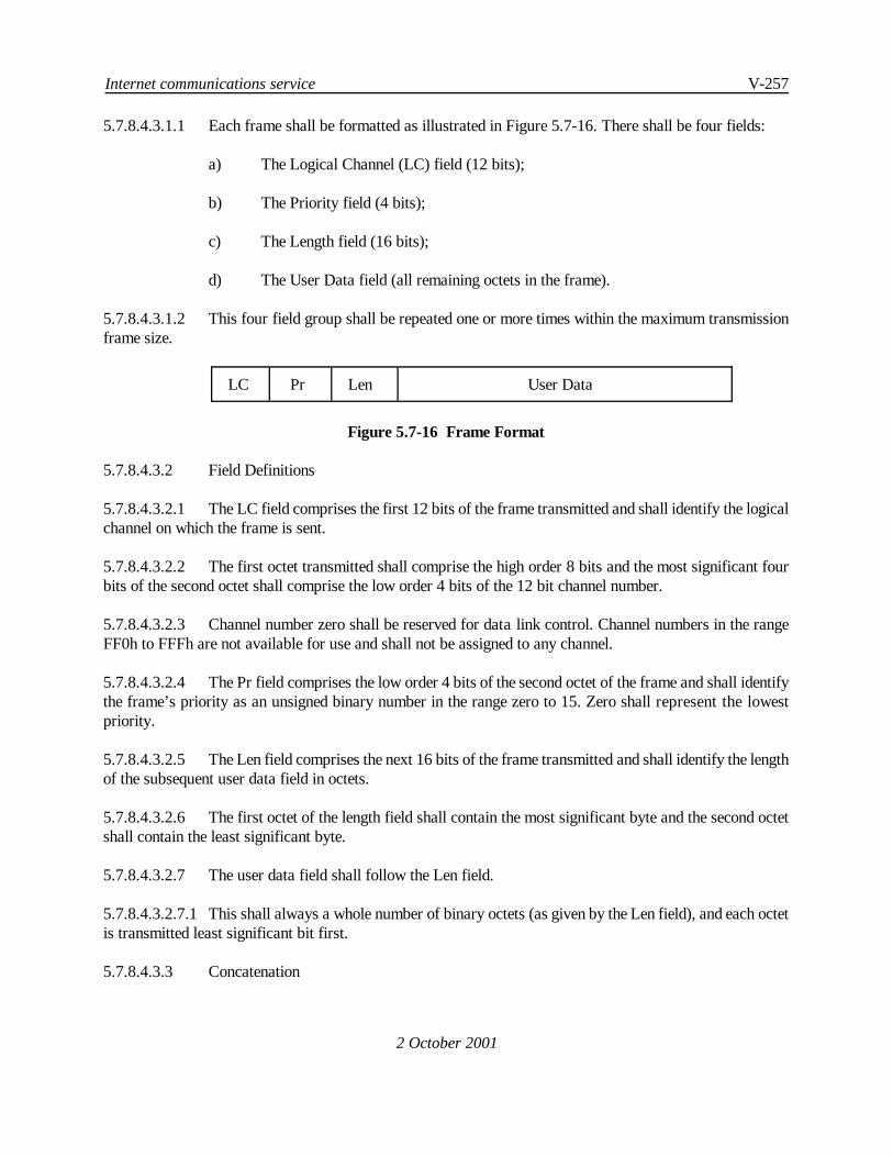
Internet communications service V-257
2 October 2001
5.7.8.4.3.1.1 Each frame shall be formatted as illustrated in Figure 5.7-16. There shall be four fields:
a) The Logical Channel (LC) field (12 bits);
b) The Priority field (4 bits);
c) The Length field (16 bits);
d) The User Data field (all remaining octets in the frame).
5.7.8.4.3.1.2 This four field group shall be repeated one or more times within the maximum transmissionframe size.
LC Pr Len User Data
Figure 5.7-16 Frame Format
5.7.8.4.3.2 Field Definitions
5.7.8.4.3.2.1 The LC field comprises the first 12 bits of the frame transmitted and shall identify the logicalchannel on which the frame is sent.
5.7.8.4.3.2.2 The first octet transmitted shall comprise the high order 8 bits and the most significant fourbits of the second octet shall comprise the low order 4 bits of the 12 bit channel number.
5.7.8.4.3.2.3 Channel number zero shall be reserved for data link control. Channel numbers in the rangeFF0h to FFFh are not available for use and shall not be assigned to any channel.
5.7.8.4.3.2.4 The Pr field comprises the low order 4 bits of the second octet of the frame and shall identifythe frame’s priority as an unsigned binary number in the range zero to 15. Zero shall represent the lowestpriority.
5.7.8.4.3.2.5 The Len field comprises the next 16 bits of the frame transmitted and shall identify the lengthof the subsequent user data field in octets.
5.7.8.4.3.2.6 The first octet of the length field shall contain the most significant byte and the second octetshall contain the least significant byte.
5.7.8.4.3.2.7 The user data field shall follow the Len field.
5.7.8.4.3.2.7.1 This shall always a whole number of binary octets (as given by the Len field), and each octetis transmitted least significant bit first.
5.7.8.4.3.3 Concatenation

V-258 Manual of Technical Provisions for the Aeronautical Telecommunication Network (ATN)
2 October 2001
5.7.8.4.3.3.1 Multiple frames addressed to the same destination may be concatenated together fortransmission in a single data link "burst" (i.e. transmission frame) up to the maximum frame size supported bythe communications media.
5.7.8.4.3.3.2 Frames of different priorities shall not be concatenated together unless:
a) the sender controls access to the medium and there are no unfulfilled requests foraccess to the medium for packets of a higher priority than the lowest priority framein the concatenated frame;
b) the sender has already been given permission to send a frame with a priority equal tothe lowest priority frame in the concatenated frame;
c) the transmission medium does not support priority based access.
Note.C In VDL Mode 3, the ground station controls access to the medium and gives permission tosend based on data priority.
5.7.8.4.3.3.3 On receipt, the received frames shall be processed in strict order of receipt.
5.7.8.4.3.4 Data Transfer
5.7.8.4.3.4.1 Once a channel has been assigned to a given purpose using the DLCP, user data may betransferred as a series of frames sent with that channel number included in the frame header.
5.7.8.4.3.4.2 The frame priority shall be set to reflect the priority of the data contained within the frame.
5.7.8.4.3.4.3 The frames on a given channel shall comprise a continuous data stream fragmented and thenre-assembled in strict transmission order. Each channel shall support bi-directional data transfer.
Note.CA given data format may specify that frame boundaries are significant in determining packetboundaries. However, this is a feature of the data format and not the channel concept.
5.7.8.4.3.4.4 On reception the channel number shall be used to determine the format of the data containedin the frame and how it is processed.
5.7.8.4.3.4.5 If a frame is received containing an unknown channel number, the frame shall be discardedand the problem reported to the peer system by using the DLCP to send a Channel Reset packet identifying theproblem.
5.7.8.4.3.4.6 If the channel has been assigned to a data compression algorithm then the user data field ofeach frame sent over the channel shall be compressed using that algorithm.
5.7.8.4.3.4.7 The compression shall take place immediately prior to transmission and in the order in whichmultiple frames sharing the same compression algorithm are concatenated into a transmission frame.
Internet communications service V-259
2 October 2001
5.7.8.4.3.4.8 On reception, the user data shall be decompressed using the corresponding decompressionalgorithm and in the order in which the frames were received and/or concatenated into the same data link frame.
Note.C It is important that the compression takes place immediately prior to transmission as datausing the same compression algorithm can be sent at different priorities and hence may overtake each otherin a transmission queue.
5.7.8.4.3.5 Congestion Handling
5.7.8.4.3.5.1 When an implementation becomes congested it shall delete sufficient low priority frames inits outgoing queues in order to return to an uncongested state.
Note.C The definition of congested and uncongested are a local matter. However, a typical strategyis to specify a "high water mark" for the number of used buffers that signals when the congested state isentered, and a "low water mark" for the number of used buffers that signals when the uncongested state hasbeen reached.
5.7.8.4.3.6 Data Compression Procedures
5.7.8.4.3.6.1 Deflate Compression
Note 1.C The Deflate Compression procedures are specified in 5.7.6.5.
Note 2.C The A/GCS permits the concurrent use of multiple Deflate compressed data streams eachassociated with a different dictionary including the empty dictionary. Each such Deflate compressed datastream is unidirectional and is associated with one or more channels. Data on each such channel iscompressed as part of the same data stream. Although the compressed data streams in each direction of datatransfer are unidirectional, when Deflate compression is applied to a channel in one direction, it is alsoapplied on the same channel in the other direction and using the same dictionary.
Note 3.C A Deflate Dictionary is an octetstring of frequently used symbols and may be up to 32KBlong. A Deflate Dictionary Identifier uniquely identifies a such a dictionary. A different octetstring may applyto the uplink direction compared with the downlink direction.
5.7.8.4.3.6.1.1 Deflate Data Compression with a given dictionary, or with no dictionary, shall only be usedwhen the corresponding compression algorithm identifier has been included in both an aircraft and groundstation’s DLS/DLR packet and the exchange of DLS/DLR packets has been completed.
5.7.8.4.3.6.1.2 Initialisation
5.7.8.4.3.6.1.2.1 When the use of the Deflate data compression algorithm has been agreed on data linkinitialisation or restart, the compressor and decompressor in each direction shall be initialised prior to their useon any channel.
5.7.8.4.3.6.1.2.2 If the use of multiple Deflate dictionaries has been agreed then a separatecompressor/decompressor shall be used for each dictionary.

V-260 Manual of Technical Provisions for the Aeronautical Telecommunication Network (ATN)
2 October 2001
5.7.8.4.3.6.1.2.3 The compressor/decompressor for a given dictionary shall be initialised by:
a) applying the contents of the dictionary into the compressor and discarding the result;
b) initialising the history buffer of the decompressor with the dictionary contents.
5.7.8.4.3.6.1.2.4 When Deflate is re-initialised following a Link Reset, the applicable dictionary, if any, shallalso be initialised as specified above.
5.7.8.4.3.6.1.3 Data Transfer
Note 1.CA data stream compressed using Deflate may be modelled as a byte stream starting at bytezero and with each successive byte identified by its relative position in the data stream expressed as an offsetfrom the start of the stream. The first byte is at offset zero.
Note 2.C Deflate maintains an active window on this data stream which may be up to 32KB wide.The stream offset to the start of this window is known as the lower window edge and the stream offset to theend of this window is known as the higher window edge. As the data stream is transferred from one systemto another both lower and higher window edges follow the data transfer with the higher window edge alwayspositioned at the current end of the stream and the lower window edge position at the start of the stream or"window size" bytes before the higher window edge. Compression is partly achieved by replacing repeatedstrings by backwards references to an earlier occurrence within this window.
Note 3.C If there is a data transfer error then the sender’s higher window edge will be in advanceof the receiver’s higher window edge. A reset procedure is needed to reset it to the receiver’s higher windowedge. Although the sender’s lower window edge will also be in advance of the receiver’s lower window edgethere is no need to adjust this.
5.7.8.4.3.6.1.3.1 If the use of Deflate and optionally a Deflate dictionary was specified in the Channel StartDLCP packet for a given channel, Deflate compression shall apply to all data sent on that channel in bothdirections of data transfer.
Note.CThere is no requirement to re-initialise an existing data compression stream when a ChannelStart is issued identifying a dictionary that is already in use. The identified channel simply joins the list ofchannels using the compressor/decompressor.
5.7.8.4.3.6.1.3.2 The User Data of a channel frame shall be compressed as a single packet as specified in5.7.6.5.2.
5.7.8.4.3.6.1.3.3 Frames shall be compressed in strict transmission order regardless of the channel with whichthey are associated.
5.7.8.4.3.6.1.3.4 The resulting compressed frame shall include the FCS.
Note.C The channel header is not compressedB only the user data.

Internet communications service V-261
2 October 2001
5.7.8.4.3.6.1.3.5 When a frame is received on a channel assigned for use with Deflate compression then theuser data shall bedecompressedusing theDeflatedecompressor associatedwith theDeflateDictionaryassignedto the channel, if any.
5.7.8.4.3.6.1.3.6 Frames shall be decompressed instrict order of reception regardless of the channel with whichthey are associated.
5.7.8.4.3.6.1.3.7 A compressor shall not use a backwards reference greater than the Deflate CompressionWindow size agreed when the data link is initialised or restarted.
5.7.8.4.3.6.1.4 Error Recovery
5.7.8.4.3.6.1.4.1 If an FCS failure is detected following decompression then the DLCP Reverse Link Resetprocedure shall be invoked in order to report and recover from the problem.
5.7.8.4.3.6.1.4.2 The sender shall indicate using the Compressed Data Stream Resync DLCP parameters:
a) the data compression algorithm to which the reset applies (i.e. Deflate) and theassociated dictionary, if any, and
b) the data stream position of the last successfully received packet, expressed as theoffset of the last received octet after decompression from the start of the data stream,i.e. when the decompressor was last initialised.
Note.C Link Reset applies only to one direction of data transfer at any one time.
5.7.8.4.3.6.1.4.3 If an FCS error occurs immediately after a link reset or the recovery of compression stateinformation on handoff, then the Reverse Link Reset procedure shall again be invoked in order to reset thecompression stream to the initial state.
Note.C This is because there is a high probability that there is a more fundamental problem, andre-initialisation of the compressed data stream is appropriate in such a case.
5.7.8.4.3.6.1.5 Receiving a Link Reset
5.7.8.4.3.6.1.5.1 When a DLCP Link Reset packet is received indicating resync of a Deflate compressedstream, the indicated compressor shall be reset.
5.7.8.4.3.6.1.5.2 The compressor shall be set so that either:
a) the Deflate Compression Window now ends with the last octet that was correctlyreceived by the peer system, as indicated by the Link Reset, or
b) theDeflate Compressor is re-initialised with the associated Deflate Dictionary, if any,loaded into the compressor.

V-262 Manual of Technical Provisions for the Aeronautical Telecommunication Network (ATN)
2 October 2001
5.7.8.4.3.6.1.5.3 A DLCP Link Reset packet shall be returned with the Compressed Data Stream ResyncParameter indicating whether the compressor was reset to the requested position or re-initialised.
5.7.8.4.3.6.1.5.4 The AK Sequence number parameter shall be included to indicate that this is a confirmationof reset by identifying the sequence number of the Link Reset Request.
5.7.8.4.3.6.1.5.5 If the indicated last octet received is in advance of the current compressor position then thecompressed data stream shall always be reset to the initial state.
Note 1.C This error is indicative of a software error in the sender or receiver and appropriatediagnostic information may also need to be logged.
Note 2.C The term "in advance of" needs to be treated with caution as stream offsets are 32-bitnumbers that wrap around to zero.
5.7.8.4.3.6.1.6 Completing the Error Recovery Procedure
5.7.8.4.3.6.1.6.1 When a DLCP Link Reset packet is received in response to a Link Reset, the decompressorshall be re-initialised to the indicated position in the data stream.
5.7.8.4.3.6.1.6.2 If the indicated position to which the data stream has been reset is in advance of the currentdecompressor position then the Data Link Restart procedures shall be invoked to restore the data link to adefined state.
Note 1.C This error is indicative of a software error in the sender or receiver and appropriatediagnostic information may also need to be logged.
Note 2.C The term "in advance of" needs to be treated with caution as stream offsets are 32-bitnumbers that wrap around to zero.
5.7.8.4.3.6.1.6.3 Any compressed data packets received on a given Deflate compressed data stream betweenthe transmission of a Link Reset and the receipt of a Link Reset acknowledgement shall be ignored.
5.7.8.4.3.6.1.7 Restoring the Deflate Compression State
Note.CRestoring the compression state is largely a ground based problem. The aircraft still has itsactive window onto the Deflate data stream. The ground side must obtain a copy of the active window forboth directions and synchronise the upper window edge with the aircraft’s active window onto the datastream.
5.7.8.4.3.6.1.7.1 When an aircraft sends a DLS to a ground station and the sending A/GCS instance usedDeflate compression for one or more channels on the data link to the previous ground station, if any, it shallinclude the Deflate Compression State parameter in the DLS for each Deflate compressor that was active andfor which the ground-to-air compression state is still available.

Internet communications service V-263
2 October 2001
5.7.8.4.3.6.1.7.2 The parameter value shall include the position of the data stream, i.e. the Higher WindowsEdge.
5.7.8.4.3.6.1.7.3 When a DLS is received from an aircraft, a ground station shall perform restoration of theDeflate compression state by:
a) obtaining the current Deflate compression state from the previous ground station, ifany, and
b) loading the appropriate Deflate Compressor and Decompressor with the compressionstate, and
c) indicating the stream positions (both ground-to-air and air-to-ground) of the restoredcompression state in the Compression State Restored parameter.
5.7.8.4.3.6.1.7.4 The restored stream position for the ground-to-air direction shall be the stream positionindicated by the aircraft in the Deflate Compression State Information parameter.
Note.C This may require adjustment of the Deflate Upper Windows edge in the retrievedcompression state information to match the current stream position of the aircraft decompressor.
5.7.8.4.3.6.1.7.5 If the aircraft stream position is in advance of the stream position obtained from the previousground station then the data stream shall be re-initialised and this indicated on the Compressed State restoredparameter.
5.7.8.4.3.6.1.7.6 An airborne system shall carry forward the compression state from the previous data linkconnection.
Note.C This may require adjustment of the Deflate Upper Windows edge in the carried forwardcompression state information to match the current stream position of the restored ground station’sdecompressor.
5.7.8.4.3.6.1.7.7 If the aircraft is unable to accept an indicated stream position in the ground-to-air direction,then the aircraft shall use the Reverse Link Reset procedure to return the data stream to the initial state.
5.7.8.4.3.6.1.7.8 If the aircraft is unable to accept an indicated stream position in the air-to-ground direction,then the aircraft shall invoke the Forward Link Reset procedures to indicate that the affected data stream isbeing returned to its initial state.
5.7.8.4.4 The Data Link Control Protocol (DLCP)
5.7.8.4.4.1 General
Note 1.C The purpose of the DLCP is to manage the assignment and use of the remaining channelsand the data compression functions.

V-264 Manual of Technical Provisions for the Aeronautical Telecommunication Network (ATN)
2 October 2001
Note 2.CChannel zero is dedicated to the Data Link Control Protocol (DLCP). However, followingData Link Initiation, all other channels are unassigned.
Note 3.C The DLCP is specified as a robust protocol designed to recover from packet loss in theMAC layer.
5.7.8.4.4.1.1 Channel zero shall be dedicated to the Data Link Control Protocol (DLCP).
5.7.8.4.4.1.2 The Data Link Control Protocol (DLCP) shall comprise the following packet formats:
1) DATA LINK START (DLS);2) DATA LINK RESTART (DLR);3) DATA LINK END (DLE);4) CHANNEL START (CS);5) CHANNEL END (CE);6) CHANNEL RESET (CR);7) LINK RESET (LR).
5.7.8.4.4.1.3 The format of each DLCP packet shall be as shown below.
ID 0000 Seq. No. Optional Parameters
Octet 0 1 3
Figure 5.7-17 Channel Independent DLCP Packet Format
ID Channel No. Seq. No. Optional Parameters
Octet 0 1 2 4
Figure 5.7-18 Channel Dependent DLCP Packet Format
5.7.8.4.4.1.4 The DLCP packet shall comprise:
a) A four bit Identifier field (ID) encoded as an unsigned binary number occupying themost significant four bits of the first byte;
Note.— Conventionally, the most signficant bit of the ID field indicates whether the ChannelIndependent format (set to 0) or the channel dependent format (set to 1) is used.
b) In the Channel Independent Format the least significant four bits of thefirst octet shallbe set to zero;
c) In the Channel Dependent Format, a 12-bit channel number shall be encoded with themost significant four bits of the channel number occupying the least significant four
Internet communications service V-265
2 October 2001
bits of the first octet, and the least significant eight bits of the channel numberencoded as the second octet;
d) A 16-bit sequence number also encoded as an unsigned binary number. The mostsignificant byte of the sequence number shall be encoded as the first octet of thesequence number field and the least significant byte shall be encoded as the secondoctet;
e) Zero, one or more optional parameters. The optional parameters are encoded as TypeLength Value (TLV) parameters using the same encoding procedures as specified forthe options part of the PDU header in ISO/IEC 8473. The permissible set of optionalparameters is specified separately for each DLCP packet.
5.7.8.4.4.1.5 The DLS, DLR, CS and CE DLCP packets may have optional user specified parameters thatare passed through transparently by the DLCP.
5.7.8.4.4.1.6 Parameter codes in the range 1000 0000 to 1100 1111 shall be reserved for user specifiedparameters.
5.7.8.4.4.1.7 An implementation receiving an unknown DLCP packet (i.e. with an unknown identifier fieldvalue) shall declare a protocol error and invoke the Data Link Restart procedures to return the data link to adefined state.
Note.— The backwards compatible mechanism for the introduction of new features is provided bythe DLS packet. Hence, an unidentified DLCP packet will always be a protocol error.
5.7.8.4.4.1.8 On data link initiation, the first DLCP packet sent shall have a sequence number of zero. Thesequence number shall be incremented for each subsequent DLCP packet.
5.7.8.4.4.1.9 On reaching the maximum value (i.e. 216-1), the sequence number shall wrap round to zero.
5.7.8.4.4.1.10 An implementation receiving a DLCP packet with a lower sequence number than thatpreviously received shall ignore the packet.
Note 1.— Because of wrap around, implementers should treat the term “lower” with a certain degreeof caution.
Note 2.— As a local matter, an implementation may limit the number of acceptable protocol errorsfrom a specific peer system and terminate the data link if that limit isexceeded.
5.7.8.4.4.1.11 Both aircraft and ground stations shall maintain a variable tracking the last received sequencenumber from the peer system.
5.7.8.4.4.1.12 This shall be set to zero on data link initiation, and thereafter set to the value of the sequencenumber in each received and processed frame.

V-266 Manual of Technical Provisions for the Aeronautical Telecommunication Network (ATN)
2 October 2001
5.7.8.4.4.1.13 With the exception of a DLS with a sequence number of zero, an incoming frame shall beignored if its sequence number is the same or less than the last received sequence number.
5.7.8.4.4.1.14 All DLCP packets shall be sent using the highest priority, i.e. priority 15.
Note.— A DLCP packet exchange may be an essential preliminary to the sending of high prioritydata and hence some DLCP packets have to be sent at the highest priority i.e. 15. As the DLCP also requiresthat packets are sent and received in sequence number order, it does not make sense to differentiate DLCPpacket priorities as this could result in unnecessary protocol errors.
5.7.8.4.4.2 DLCP Procedures
5.7.8.4.4.2.1 Data Link Initialisation
5.7.8.4.4.2.1.1 Data Link Initialisation shall be performed by an aircraft only.
5.7.8.4.4.2.1.2 When initialising a data link, the aircraft shall mark all channels other than channel zero asunassigned and send a DLS packet.
5.7.8.4.4.2.1.3 On receipt of a DLS packet. the ground station shall also mark all channels other than channelzero as unassigned.
5.7.8.4.4.2.1.4 It shall then apply the Compression State recoveryprocedures specified in5.7.8.4.3.6.2.6, andreturn its own DLS packet in acknowledgement.
5.7.8.4.4.2.1.5 The DLS’s sequence number shall be set to zero on data link initialisation. The DLS sent inacknowledgement to a received DLS shall have the same sequence number as in the received DLS.
5.7.8.4.4.2.1.6 A timer t1 shall be started whenever a DLS is sent, and reset when the DLS is acknowledged.
5.7.8.4.4.2.1.7 If timer t1 expires before the DLS is acknowledged then the sequence number shall beincremented, the DLS shall be sent and timer t1 restarted.
5.7.8.4.4.2.1.8 Each time timer t1 is restarted the timer duration shall be increased by 50%.
Note.— The purpose of this procedure is to ensure that a timer set to an unrealistically short intervaldoes not prevent communication.
5.7.8.4.4.2.1.9 If a ground station receives a further DLS initialising the data link (i.e. with higher sequencenumber), it shall:
a) deallocate any channel allocations it had made since the receipt of the previous DLS,and
b) again return its own DLS packet in acknowledgement.
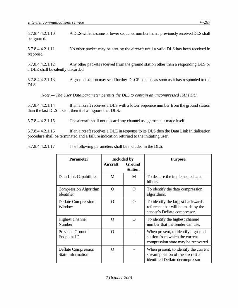
Internet communications service V-267
2 October 2001
5.7.8.4.4.2.1.10 A DLS with the same or lower sequence number than a previously received DLS shallbe ignored.
5.7.8.4.4.2.1.11 No other packet may be sent by the aircraft until a valid DLS has been received inresponse.
5.7.8.4.4.2.1.12 Any other packets received from the ground station other than a responding DLS ora DLE shall be silently discarded.
5.7.8.4.4.2.1.13 A ground station may send further DLCP packets as soon as it has responded to theDLS.
Note.— The User Data parameter permits the DLS to contain an uncompressed ISH PDU.
5.7.8.4.4.2.1.14 If an aircraft receives a DLS with a lower sequence number from the ground stationthan the last DLS it sent, then it shall ignore that DLS.
5.7.8.4.4.2.1.15 The aircraft shall not discard any channel assignments it made itself.
5.7.8.4.4.2.1.16 If an aircraft receives a DLE in response to its DLS then the Data Link Initialisationprocedure shall be terminated and a failure indication returned to the initiating user.
5.7.8.4.4.2.1.17 The following parameters shall be included in the DLS:
Parameter Included byAircraft Ground
Station
Purpose
Data Link Capabilities M M To declare the implemented capa-bilities.
Compression AlgorithmIdentifier
O O To identify the data compressionalgorithms.
Deflate CompressionWindow
O O To identify the largest backwardsreference that will be made by thesender’s Deflate compressor.
Highest ChannelNumber
O O To identify the highest channelnumber that the sender can use.
Previous GroundEndpoint ID
O - When present, to identify a groundstation from which the currentcompression state may be recovered.
Deflate CompressionState Information
O - When present, to identify the currentstream position of the aircraft’sidentified Deflate decompressor.

V-268 Manual of Technical Provisions for the Aeronautical Telecommunication Network (ATN)
Parameter Included byAircraft Ground
Station
Purpose
2 October 2001
Ground Endpoint ID - M To identify uniquely the groundstation as a data link endpoint.
Compression StateRestored
- O When present, to indicate that thecompression state was recoveredfrom the identified ground station.
UncompressedChannels Restored
- O When present, to indicate that alluncompressed channels have beenrestored.
User Data O O To exchange a user data packet, e.g.an ISH PDU, on the DLS.
Note.— When LREF is used to compress CLNP PDUs, the user parameters specified in 5.7.8.2.4.1.2may also be present in the DLS.
5.7.8.4.4.2.1.18 On completion of the exchange of DLS packets:
a) Only those capabilities in common between aircraft and ground station shall be usedon the Data Link;
b) The highest channel number available for allocation shall be the lower of the HighestChannel Numbers supported by aircraft and ground station.
Note.— Initialisation of the Deflate Compressor/Decompressor is specified in 5.7.8.4.3.6.1.
5.7.8.4.4.2.1.19 If a user data parameter is present in an incoming DLS, the user packet containedwithin it shall be passed to the service user.
5.7.8.4.4.2.1.20 Negotiation of Data Link Capabilities
5.7.8.4.4.2.1.20.1 An aircraft shall identify its supported data link capabilities by including a Data LinkCapabilities parameter in its DLS and setting the appropriate bits.
5.7.8.4.4.2.1.20.2 A ground station shall inspect the Data Link Capabilities parameter in a receivedDLS and determine the common set of availability data link capabilities.
5.7.8.4.4.2.1.20.3 The ground station shall return this common set in its DLS response by including aData Link Capabilities parameter and setting the bits that correspond to the commonset of capabilities.
5.7.8.4.4.2.1.20.4 Any unrecognised Data Link Capabilities shall be ignored by the ground station.
Internet communications service V-269
2 October 2001
5.7.8.4.4.2.1.21 Negotiation of Compression Algorithms
5.7.8.4.4.2.1.21.1 An aircraft shall identify the compression algorithms and versions it supports byincluding a “Compression Algorithm identifier” parameter for each such algorithmin its DLS.
5.7.8.4.4.2.1.21.2 Each such parameter shall identify the algorithm and version supported.
5.7.8.4.4.2.1.21.3 A ground station shall determine the common set of supported compressionalgorithms and versions by comparing the list of compression algorithms given in theaircraft’s DLS with those compression algorithms it supports.
5.7.8.4.4.2.1.21.4 The ground station shall list this common set in its DLS response by including aCompression AlgorithmIdentifier parameter for each such algorithmidentifying bothalgorithm and version supported.
5.7.8.4.4.2.1.21.5 When the ground station supports an earlier version to that supported by the aircraft,then this earlier version shall be that included in the common set of supportedalgorithms.
5.7.8.4.4.2.1.21.6 Any unknown Compression Algorithms shall be ignored by the ground station.
Note.— Version numbers are intended to be used incrementally and if a given version is supportedthen all earlier versions are also supported. The ground station may therefore respond with an earlierversion number if the version proposed is not supported. It is implicitly assumed that the aircraft will supportthis earlier version.
5.7.8.4.4.2.1.22 Restoring the Compression State
Note.— The procedures for restoring the Deflate Compression State are specified in 5.7.8.4.3.6.2.6.
5.7.8.4.4.2.1.22.1 If the aircraft’s A/GCS instance has retained compression state information from aprevious data link connection, it shall include:
a) The Previous Ground Endpoint ID parameter in its DLS. This shall contain theGround Endpoint Identifier that had been uplinked in the DLS fromthe ground stationwith which the previous data link connection had been established;
b) Optionally, the Deflate Compression State Information parameter for each Deflatecompressor. This shall contain the algorithm id for the compressor followed by thecurrent position of the ground-to-air data stream compressed by Deflate.
5.7.8.4.4.2.1.22.2 If supported by the ground station, the ground station shall use a “Previous GroundEndpoint ID” parameter in the aircraft’s DLS to contact the identified ground stationand to obtain from it:

V-270 Manual of Technical Provisions for the Aeronautical Telecommunication Network (ATN)
2 October 2001
a) The compression state for each compression algorithm supported by both groundstation and aircraft, and
b) The current channel assignments, including those of channels not associated with anycompressor.
5.7.8.4.4.2.1.22.3 If the compression state is successfully obtained, then ground station shall restore thecurrent channel assignments including those channels not associated with anycompressor and set its own A/GCS compression/decompression functions to theobtained state.
5.7.8.4.4.2.1.22.4 The ground station shall include a “Compression State Restored” parameter in thereturned DLS for each compression algorithmrestored, indicating the streampositionfor which compression was restored.
Note 1.— The compression state may include Deflate compression state information and stateinformation from any other A/GCS compression algorithm. it also includes the current channel allocationsfor each compression algorithm, which are implicitly restored. This is because compression algorithms arelinked to channels.
Note 2.—LREF state is restored separately (see section 5.7.8.2.4.1.3). However, LREF compressioncannot be restored unless the channel assigned to LREF is also restored.
Note 3.— It is possible to restore the channel assignments only by including a Compression StateRestored parameter restoring the stream to the initial state.
5.7.8.4.4.2.1.22.5 The ground station shall include an “Uncompressed Channels Restored” parameterin the returned DLS if it is able to restore channel assignments for channels notassociated with any compressor.
Note 1.— Channel zero is always available and there is no need to include this parameter if thereis no uncompressed channel other than channel zero .
Note 2.— It is possible to restore the uncompressed channel assignments only.
5.7.8.4.4.2.1.22.6 When an aircraft receives a DLS response that includes a “Compression StateRestored” parameter it shall restore the indicated compression functions andchannelsto their state when the data link with the previous ground station was terminated.
Note.— If the ground station is the same as the previous ground station – which is very likely whena single ground station is connected to several ground stations in a given geographical error, then restoringthe compression state should be trivial (i.e. the information is available locally). When the ground stationis remote then a communications protocol will be needed to recover the compression state. This could, forexample be the Hypertext Transfer Protocol (http) with the Ground Endpoint ID and aircraft address usedto construct a conventional URL from where the required compression state will be found.

Internet communications service V-271
2 October 2001
5.7.8.4.4.2.1.23 Data Link Initiation Refusal
5.7.8.4.4.2.1.23.1 A ground station that is unable to accept a Data Link Initiation request from anAircraft shall respond to the DLS packet with a DLE packet with an appropriatediagnostic code.
Note.— If a transient problem is signalled then it is a local matter as to whether a further attemptis made to establish a data link after some back off period or whether an alternative ground station iscontacted, if available.
5.7.8.4.4.2.2 Data Link Restart
5.7.8.4.4.2.2.1 The Data Link Restart procedures shall be performed in order to recover from a seriousprotocol error as specified by this specification.
5.7.8.4.4.2.2.2 The Data Link Restart procedure may be initiated by either the aircraft or the ground station.
5.7.8.4.4.2.2.3 To initiate a Data Link Restart, the initiator shall send a DLR packet. The packet’s sequencenumber shall be the next sequence number in the series.
5.7.8.4.4.2.2.4 When a system receives a DLR packet which is not in response to a Data Link Restart thatit initiated itself, the system shall deallocate all allocated channels and re-initialise all compression functions.
5.7.8.4.4.2.2.5 It shall respond with a DLR packet acknowledging the restart.
Note.— The AK Sequence number parameter is used to indicate that this is a response and to whichDLR it is a response.
5.7.8.4.4.2.2.6 Once a systemhas initiateda Data Link Restart, it shall ignore and discard all received packetson all channels except for another DLR.
5.7.8.4.4.2.2.7 When it receives a DLR acknowledging its own Data Link Restart, the systemshall deallocateall allocated channels and re-initialise all compression functions.
Note.— Exceptionally Data Link Restart procedures may be initiated by both systems simultaneously.5.7.8.4.4.2.2.4 above applies even when a system is waiting for a response to its own DLR.
5.7.8.4.4.2.2.8 A timer t1 shall be started whenever a DLR is sent, and reset when the DLR is acknowledged.
5.7.8.4.4.2.2.9 If timer t1 expires before the DLR is acknowledged then the DLR shall be sent again and timert1 restarted. On retransmission, the sequence number shall be the next sequence number in the series.
5.7.8.4.4.2.2.10 Each time timer t1 is restarted the timer duration shall be increased by 50%.
Note.— The purpose of this procedure is to ensure that a timer set to an unrealistically short intervaldoes not prevent communication.

V-272 Manual of Technical Provisions for the Aeronautical Telecommunication Network (ATN)
2 October 2001
5.7.8.4.4.2.2.11 The procedures for negotiation of data link capabilities and compression algorithmnegotiation shall be as specified for Data Link Initiation.
Note 1.— There is no mechanism for restoring the compression state or channel assignments on aData Link Restart.
Note 2.— There is no change to shared session key on a Data Link Restart.
5.7.8.4.4.2.2.12 The following parameters shall be included in the DLR for a Data Link Restart:
Parameter Included byAircraft Ground
Station
Purpose
Data Link Capabilities M M To declare the implemented capa-bilities.
Compression AlgorithmIdentifier
O O To identify the supported datacompression algorithms.
Deflate CompressionWindow
O O To identify the largest backwardsreference that will be made by thesender’s Deflate compressor.
Highest ChannelNumber
O O To identify the highest channelnumber that the sender can use.
AK Sequence Number M M To acknowledge the received DLR.Required on a response only.
Diagnostic M M To indicate the reason for therestart.
5.7.8.4.4.2.2.13 On completion of the exchange of DLR packets for a Data Link Restart:
a) Only those capabilities in common between aircraft and ground station shall be usedon the data link;
b) The highest channel number available for allocation shall be the lower of the HighestChannel Numbers supported by aircraft and ground station.
Note.C The data link is now in its initial stateexcept for any shared session key which remainsunchanged.
5.7.8.4.4.2.2.14 If a DLR is received apparently in response to a DLR that had been sent previouslybut which is unexpected, then the Data Link Restart procedures shall be invoked to restore the data link to adefined state.

Internet communications service V-273
2 October 2001
5.7.8.4.4.2.3 Data Link Termination
5.7.8.4.4.2.3.1 The data link shall be implicitly terminated either:
a) when the underlying data link reports loss of communications, or
b) when a DLS packet is received. The DLS packet shall be processed as specified in5.7.8.4.4.2.1.
5.7.8.4.4.2.3.2 The data link shall be explicitly terminated by either airborne or ground station sending a DLEpacket.
5.7.8.4.4.2.3.3 Once a DLE packet has been sent, any further packet received from the peer system shall besilently discarded and the DLE re-sent.
5.7.8.4.4.2.3.4 On receipt of a DLE packet a system shall regard the data link as being terminated.
5.7.8.4.4.2.3.5 Once a data link has been terminated no further data transfers shall be initiated.
5.7.8.4.4.2.3.6 However, channel allocation and compression state shall be retained for possible use on thenext data link connection.
Note.C The implicit termination of a data link when a DLS is received is compatible with theretransmission of a DLS (see 5.7.8.4.4.2.1).
5.7.8.4.4.2.4 Channel Allocation
5.7.8.4.4.2.4.1 The CS packet shall be used to assign the purpose and use of a logical channel, as indicatedby the packet’s parameters.
5.7.8.4.4.2.4.2 A Data Format parameter shall always be present in the CS packet and shall indicate the typeof data for which the channel is assigned.
5.7.8.4.4.2.4.3 A Compression Algorithm Identifier shall be present when the channel is to be associated witha compression algorithm.
5.7.8.4.4.2.4.4 The Compression Algorithm Identifier shall be used to identify the compressor anddecompressor with which the channel is associated.
5.7.8.4.4.2.4.5 If a CS packet is received for a channel that is already assigned and:
a) the assignment had been previously made by the sender of the CS packet, then the CSpacket shall re-assign the channel to the new purpose and use;
b) the assignment had been previously made by the receiver of the CS packet, then theCS packet is in error and a Channel Reset shall be sent in response.
V-274 Manual of Technical Provisions for the Aeronautical Telecommunication Network (ATN)
2 October 2001
Note.C If the channel assignment or re-assignment is accepted then no response is expected.
5.7.8.4.4.2.4.6 The sender of the CS packet shall be the channel initiator and the receiver shall be the channelresponder.
5.7.8.4.4.2.4.7 When choosing a logical channel to assign, an aircraft shall choose the highest numberedlogical channel available for assignment while a ground station shall choose the lowest numbered logicalchannel available.
5.7.8.4.4.2.4.8 If no channel is available, a lesser importance channel shall be selected out of those previouslyassigned by the sender of the CS packet, and re-assigned to the new purpose and use.
5.7.8.4.4.2.4.9 If no such channel is available, the request for a new channel assignment shall fail and theservice user notified.
Note.C It is a local matter as to what constitutes "lesser importance".
5.7.8.4.4.2.4.10 In order to prevent channel assignment race conditions, there shall be at least onechannel that remains unassigned at all times.
5.7.8.4.4.2.4.11 A single compression algorithm may be specified for the channel out of those incommon between initiator and responder.
5.7.8.4.4.2.4.12 If a CS packet is received attempting to assign a channel number greater than thatwhich the receiving system declared as the "highest channel number" in its DLS or DLR packet, then thechannel assignment shall be rejected by returning a Channel Reset, with an appropriate diagnostic code.
5.7.8.4.4.2.4.13 An unknown parameter code or the use of an unrecognised data format shall berejected as an error and a Channel Reset packet returned in order to report the error, with an appropriatediagnostic code. The channel shall return to the unassigned state.
5.7.8.4.4.2.5 Channel Deallocation
5.7.8.4.4.2.5.1 The Channel End (CE) packet is sent in order to return a channel to the unassigned state. Itshall be sent only by the channel initiator.
5.7.8.4.4.2.5.2 Receipt of a CE by the channel initiator shall be regarded as a protocol error and the DLRprocedure shall be used to re-initialise the data link.
5.7.8.4.4.2.5.3 A CE received for an unassigned channel shall be silently ignored.
5.7.8.4.4.2.6 Link Reset Procedures
5.7.8.4.4.2.6.1 The Link Reset procedures shall be used by a data compression function that operates on datafrom one or more channels, in order to recover from errors in the compression procedure that affect thosechannels.

Internet communications service V-275
2 October 2001
Note 1.C Either system may perform a link reset.
Note 2.C The only data compression procedure currently specified to use this procedure is Deflate.
5.7.8.4.4.2.6.2 Forward Link Reset Procedure
5.7.8.4.4.2.6.2.1 The Forward Link Reset Procedureshall beusedtoannouncethat the compressed data streamfrom the initiator of the procedure to the receiver is being reset to its initial state.
5.7.8.4.4.2.6.2.2 To invoke the Forward Link Reset Procedure, the initiator shall send a Link Reset packet tothe receiver.
5.7.8.4.4.2.6.2.3 The Compression Algorithm Identifier parameter shall be present and identifies the affecteddata compression algorithm and hence the affected data stream and channels.
5.7.8.4.4.2.6.2.4 The Diagnostic parameter shall be present and indicates the reason for the Link Reset.
5.7.8.4.4.2.6.2.5 When a Forward Link Reset is sent, the affected data stream compressor is re-initialised.
5.7.8.4.4.2.6.2.6 When a Forward Link Reset is received, the affected data stream decompressor is re-initialised.
Note.C No acknowledgement of receipt is required.
5.7.8.4.4.2.6.3 Reverse Link Reset Procedure
5.7.8.4.4.2.6.3.1 To initiate a Reverse Link Reset, the initiator shall sendanLR packet containing thefollowingparameters:
Compressed Data Stream Resync To identify the affected compression algorithmand by implication the affected channels, and toindicate the postion in the data stream to which areset may take place.
Diagnostic Reason To identify the reason for the link reset.
5.7.8.4.4.2.6.3.2 Additional optional parameters may be specified for the specific compression algorithm.
5.7.8.4.4.2.6.3.3 When a Data Link Reset is received, the identified data compression function shall be alerted,and a Link Reset message returned acknowledging the Link Reset.
5.7.8.4.4.2.6.3.4 This shall include the following parameters:

V-276 Manual of Technical Provisions for the Aeronautical Telecommunication Network (ATN)
2 October 2001
Compressed Data Stream Resync To identify the affected compression algorithmand by implication the affected channels, and toindicate the postion in the data stream to which areset may take place.
AK Sequence Number To indicate the sequence number of the LRpacket that initated the link reset.
5.7.8.4.4.2.6.3.5 Additional optional parameters may be specified for the specific compression algorithm.
5.7.8.4.4.2.6.3.6 When such a Data Link Reset Response is received the identified data compression functionshall be re-synchronised to the indicated stream position.
Note.C The procedures carried out by the data compression function in response to a Data LinkReset are specific to that function.
5.7.8.4.4.2.6.3.7 A timer t1 shall be started whenever an LR is sent to initiate a link reset, and reset when theLR is acknowledged.
5.7.8.4.4.2.6.3.8 If timer t1 expires before the LR is acknowledged, then the LR shall be sent again and timert1 restarted.
Note.C The sequence number is incremented for each retransmission.
5.7.8.4.4.2.6.3.9 Each time timer t1 is restarted the timer duration shall be increased by 50%.
Note.CThe purpose of this procedure is to ensure that a timer set to an unrealistically short intervaldoes not result in a communications failure.
5.7.8.4.4.2.6.3.10 If a Forward Link Reset is received for the same compression algorithm while awaiting aresponse to a Reverse Link Reset, the Reverse Link Reset procedures shall be abandoned and the Forward LinkReset processed as described in5.7.8.4.4.2.6.2.
5.7.8.4.4.3 DLCP Packet Formats
Note.C The DLCP procedures are specified in 5.7.8.4.4.2. Only the packet formats are specifiedhere.
5.7.8.4.4.3.1 Data Link Start (DLS)
Identifier (ID) 1
5.7.8.4.4.3.1.1 The DLS packet shall be sent to initialise a data link.
5.7.8.4.4.3.1.2 The following optional parameters are specified for the DLS packet:

Internet communications service V-277
2 October 2001
1) Data Link Capabilities;2) Compression Algorithm Identifier;3) Deflate Compression Window;4) Highest Channel Number;5) Previous Ground Endpoint ID;6) Ground Endpoint ID;7) Compression State Restored;8) Deflate Compression State Information;9) Security Algorithm ID;10) Random Value;11) Public Key;12) Public Key Certificate;13) User Data.
5.7.8.4.4.3.1.3 The parameter codes for these parameters shall be as specified for each parameter.
5.7.8.4.4.3.1.4 On receipt an unrecognised parameter shall be silently ignored.
5.7.8.4.4.3.2 Data Link Restart (DLR)
Identifier (ID) 10
5.7.8.4.4.3.2.1 The DLR packet shall be sent to restart a data link after an error has occurred.
5.7.8.4.4.3.2.2 The following optional parameters are specified for the DLR packet:
1) Data Link Capabilities;2) AK Sequence Number;3) Compression Algorithm Identifier;4) Deflate Compression Window;5) Highest Channel Number;6) Previous Ground Endpoint ID;7) Ground Endpoint ID;8) Diagnostic (to indicate the restart reason).
5.7.8.4.4.3.2.3 The parameter codes for these parameters shall be as specified for each parameter.
5.7.8.4.4.3.2.4 On receipt an unrecognised parameter shall be silently ignored.
5.7.8.4.4.3.3 Data Link End (DLE)
Identifier (ID) 11
5.7.8.4.4.3.3.1 The DLE packet shall be sent to terminate or reject the initiation of a data link.

V-278 Manual of Technical Provisions for the Aeronautical Telecommunication Network (ATN)
2 October 2001
5.7.8.4.4.3.3.2 The following optional parameters are specified for the DLE packet:
1) Diagnostic.
5.7.8.4.4.3.3.3 The parameter codes for these parameters shall be as specified for each parameter.
5.7.8.4.4.3.3.4 On receipt, an unrecognised parameter shall be silently ignored.
5.7.8.4.4.3.4 Channel Start (CS)
Note.C The purpose of the CS packet is to assign the use of a previously unassigned channel andto define its operational parameters.
Identifier (ID) 1000
5.7.8.4.4.3.4.1 The CS packet header shall include the logical channel number to which the CS applies.
5.7.8.4.4.3.4.2 The following parameters are specified for the CS packet:
1) Compression Algorithm Identifier (optional);2) Data Format.
5.7.8.4.4.3.4.3 The parameter codes for these parameters shall be as specified for each parameter.
5.7.8.4.4.3.4.4 On receipt an unrecognised parameter shall be rejected as a protocol error.
5.7.8.4.4.3.5 Channel End (CE)
Note.C The purpose of the CE packet is to restore a channel to the unassigned state.
Identifier (ID) 1001
5.7.8.4.4.3.5.1 The CE packet header shall include the logical channel number to which the CE applies.
5.7.8.4.4.3.6 Channel Reset (CR)
Note.C The purpose of the CR packet is to signal a problem in channel assignment or use, and torestore the channel to a defined state.
Identifier (ID) 1010
5.7.8.4.4.3.6.1 The CR packet header shall include the logical channel number to which the CR applies.
5.7.8.4.4.3.6.2 The parameter codes for these parameters shall be as specified for each parameter.

Internet communications service V-279
2 October 2001
5.7.8.4.4.3.6.3 On receipt an unrecognised parameter shall be rejected as a protocol error.
5.7.8.4.4.3.6.4 The CR packet shall be sent only:
a) when required by this specification in order to signal a problem with a channelassignment, or
b) on the request of the service user in order to report a problem in the data sent over thechannel.
5.7.8.4.4.3.6.5 When a CR packet has been sent on the request of the service user:
a) The Diagnostic parameter shall indicate "User Problem";
b) The User Diagnostic parameter shall be present and set to a value specified by theservice user.
5.7.8.4.4.3.6.6 The following optional parameters are specified for the CR packet:
1) Diagnostic;2) User Diagnostic;3) AK Sequence Number.
5.7.8.4.4.3.6.7 If no User Diagnostic parameter is present then a Channel Reset results in the channelbecoming unassigned.
5.7.8.4.4.3.6.8 If a User Diagnostic parameter is present then a timer t1 shall be started by the sender.
5.7.8.4.4.3.6.9 All user data received on the same channel shall be discarded until a Channel Reset is returnedby the peer system acknowledging receipt of the Channel Reset by including an AK Sequence numberparameter containing the sequence number of the original Channel Reset.
5.7.8.4.4.3.6.10 If timer t1 expires before such a Channel Reset is received, the Channel Reset shallbe sent again, and timer t1 restarted.
Note.C The DLCP protocol requires that the sequence number is incremented for eachretransmission.
5.7.8.4.4.3.6.11 Each time timer t1 is restarted the timer duration shall be increased by 50%.
Note.CThe purpose of this procedure is to ensure that a timer set to an unrealistically short intervaldoes not result in communications failure.
5.7.8.4.4.3.6.12 When a Channel Reset is received from a peer system with a User Diagnosticparameters but without an AK Sequence Number parameter, the Channel Reset and Diagnostic shall bereported to the service user and a Channel Reset returned in response.

V-280 Manual of Technical Provisions for the Aeronautical Telecommunication Network (ATN)
2 October 2001
5.7.8.4.4.3.6.13 This shall include the AK Sequence Number parameter containing the sequencenumber of the received Channel Reset.
5.7.8.4.4.3.6.14 No other parameters shall be included.
5.7.8.4.4.3.6.15 When a Channel Reset is received from a peer system an AK Sequence Numberparameter that is not in acknowledgement of the last sent Channel Reset, the Channel Reset shall be ignored.
5.7.8.4.4.3.7 Link Reset (LR)
Note 1.C The purpose of the LR packet is to re-initialise a compressed data stream or to restart itat an identified point.
Note 2.C A Link Reset affects all channels using the affected compressed data stream.
Identifier (ID) 111
5.7.8.4.4.3.7.1 The Link Reset packet shall be sent when an error is detected in a received Deflate compresseddata stream, in order to return the data stream to a defined state.
5.7.8.4.4.3.7.2 The following optional parameters are specified for the Link Reset packet:
1) Compressed Data Stream Resync;2) Compression Algorithm ID;3) Diagnostic;4) AK Sequence Number.
5.7.8.4.4.3.7.3 The parameter codes for these parameters shall be as specified for each parameter.
5.7.8.4.4.3.7.4 On receipt, an unrecognised parameter shall be rejected as a protocol error.
5.7.8.4.4.4 DLCP Optional Parameters
5.7.8.4.4.4.1 Data Link Capabilities Parameter
Parameter Code 0000 0001
Parameter Length variable
Parameter Value see below
5.7.8.4.4.4.1.1 The parameter shall be interpreted as a variable length bitmap indicating support of data linkcapabilities specified in this and subsequent standards.

Internet communications service V-281
2 October 2001
Note.CAn important purpose of this parameter is to provide for the introduction of new capabilitiesin a backwards compatible manner. Therefore this specification requires implementations to ignorecapabilities that they do not understand and to handle longer length parameters than they would otherwiseexpect.
5.7.8.4.4.4.1.2 For the purposes of this specification, the bits in the bitmap shall be numbered b0 through tobn where b0 is the least significant bit in the bitmap and bn is the most significant bit.
5.7.8.4.4.4.1.3 The sender shall send the minimum number of octets in order to transmit all non-zero bits inthe bitmap.
5.7.8.4.4.4.1.4 A receiver shall be able to accept any length bitmap up to the maximum length permitted bythe encoding rules.
5.7.8.4.4.4.1.5 The Data Link Capabilities parameter shall be interpreted as follows:
Bit No. Capability
0 ISO TR 9577 Format Data
1 LREF Data Format
2 Reformatted CLNP Headers
3 IPv4
5.7.8.4.4.4.1.6 The sender shall set the corresponding bit to one in order to claim support of the associatedcapability.
5.7.8.4.4.4.1.7 The data link capabilities that are used for communication between the sender and receivershall be those in common between those declared in the sender’s DLR and those declared in the DLR sent backin response.
5.7.8.4.4.4.1.8 Any unrecognised bits in the capabilities bitmap shall be ignored.
Note.C LREF Data Compression is listed here as a capability for efficiency reasons. Formally, itis a capability of the service user.
5.7.8.4.4.4.2 Compression Algorithm Identifier
Parameter Code 0000 0010
Parameter Length 0, 2 or 3 octets
Parameter Value Algorithm ID and version
Note 1.C The purpose of the Compression Algorithm Identifier is to identify a CompressionAlgorithm supported by the sender of the DLS or DLR, and the version supported.

V-282 Manual of Technical Provisions for the Aeronautical Telecommunication Network (ATN)
2 October 2001
Note 2.C Currently Deflate is the only compression algorithm that will be identified. However, it isintended that each Deflate dictionary supported is identified by a unique Algorithm ID.
5.7.8.4.4.4.2.1 The parameter value shall be either:
a) an unsigned 16-bit unsigned binary number that is a unique identifier for acompression algorithm. Compression Algorithm identifiers shall be globally knownand the registry of Compression Algorithm identifiers shall be maintained by ICAO,or
b) a Compression Algorithm identifier as defined above followed by an 8-bit unsignedbinary number that is the version number of the algorithm.
5.7.8.4.4.4.2.2 If no version number is present then version zero shall be assumed for a DLS or DLR.
5.7.8.4.4.4.2.3 Otherwise, the negotiated version, as agreed on data link initialisation or restart, shall beassumed.
5.7.8.4.4.4.2.4 This parameter may occur more than once in a DLS or DLR and is repeated for eachcompression algorithm supported.
5.7.8.4.4.4.2.5 A compression algorithm ID of zero is defined by this specification to identify the Deflatestream compression algorithm with no initialisation dictionary.
5.7.8.4.4.4.2.6 If the parameter length is zero and no parameter value is present then this shall equate to aparameter value of zero.
Note.CVersion number are allocated incrementally and support for a given version number impliessupport for all earlier versions. For example, support for version 2 implies that versions 1 and 0 are alsosupported.
5.7.8.4.4.4.3 Deflate Compression Window
Parameter Code 0000 0011
Parameter Length 1 octet
Parameter Value An unsigned binary number inthe range 10 to 15
Note.CThe purpose of this parameter is to declare the largest backwards reference that will be madein the Sender’s a Deflate compressed data steam. The receiver can use this information to reduce the sizeof the decompression buffer.
5.7.8.4.4.4.3.1 This parameter shall be included in a DLR in order to signal the largest backwards referencethat will be made in the Sender’s a Deflate compressed data steam.

Internet communications service V-283
2 October 2001
5.7.8.4.4.4.3.2 The parameter value shall be a number n in the range 10 to 15.
5.7.8.4.4.4.3.3 The largest backwards reference shall be calculated as 2n-1.
5.7.8.4.4.4.3.4 If the parameter is omitted, then a value of n shall default to 15.
Note.C There is no requirement for the Default Compression Window to be the same in bothdirections.
5.7.8.4.4.4.4 Highest Channel Number
Parameter Code 0000 0100
Parameter Length 2 octets
Parameter Value Highest assignable Channel Number
Note.C The purpose of this parameter is to indicate the maximum number of channels supported bythe sender. The actual number of channels available will be the lower of the maximum supported by bothsides.
5.7.8.4.4.4.4.1 This parameter shall be included in a DLR to indicate the highest assignable channel number.
5.7.8.4.4.4.4.2 The sending system will not attempt to assign a channel number greater than the parametervalue, nor will it accept a channel number greater than the parameter value.
5.7.8.4.4.4.4.3 If this parameter is not included then the highest assignable channel number shall default to15.
5.7.8.4.4.4.5 Ground Endpoint ID
Parameter Code 0000 0101
Parameter Length variable
Parameter Value Ground Endpoint Identifier
Note.C The purpose of the parameter is to enable the ground station to provide the aircraft withsome unique identifier that can be used on a subsequent data link to restore the compression state.
5.7.8.4.4.4.5.1 The Ground Endpoint ID parameter shall be included in every DLS sent to an aircraft.
5.7.8.4.4.4.5.2 The Ground Endpoint ID parameter shall provide a unique identifier for the ground station.
Note.C An example of a unique identifier is the NET of the ATN Router.
5.7.8.4.4.4.6 Previous Ground Endpoint ID

V-284 Manual of Technical Provisions for the Aeronautical Telecommunication Network (ATN)
2 October 2001
Parameter Code 0000 0110
Parameter Length variable
Parameter Value Previous Ground Endpoint Identifier
Note.C The purpose of this parameter is to identify the previous ground station on the same type ofAir/Ground Subnetwork which the aircraft used for data communications using the procedures specified bythis SNDCF. It is used as a hint to the receiver that it may be possible to transfer the compression state fromthe previous connection to the new one.
5.7.8.4.4.4.6.1 The Previous Ground Endpoint ID shall only be included in the DLS sent by an aircraft toinitialise a new data link.
5.7.8.4.4.4.6.2 It shall not be sent by a ground station when performing a Data Link Restart.
5.7.8.4.4.4.7 Compression State Restored
Parameter Code 0000 0111
Parameter Length 2, 6 or 10 octets
Parameter Value Compression Algorithm IDfollowed by stream position
Note 1.C This parameter is included by a ground station in order to indicate to an aircraft that ithas been able to recover the compression state for the indicated Compression Algorithm. All channelassignments are restored; the compressors and decompressors are in the same state as at when the data linkwas closed.
Note 2.C It occurs once for each data compression algorithm restored.
Note 3.C This parameter is not used to signal restoration of the LREF Directory. This is formallya service user function and is signalled via a parameter code reserved for user parameters.
Note 4.CThere is no need to signal the compression algorithm version as it is not possible to changealgorithm versions on handoff. The same version is maintained implicitly.
5.7.8.4.4.4.7.1 The Compression State Restored parameter shall only be included in a DLS sent by a groundstation to an aircraft, and to indicate that the compression state has been recovered from the ground stationattached to the previous ground station, and for the specified compression algorithm.
5.7.8.4.4.4.7.2 The parameter value shall comprise three fields:
1) A 16-bit compression algorithm identifier;
2) Optionally, the data stream position in the air-to-ground direction;

Internet communications service V-285
2 October 2001
3) Optionally, the data stream position in the ground-to-air direction.
Note.C This encoding implies that a ground-to-air stream position can only be indicated when anair-to-ground stream position is also indicated.
5.7.8.4.4.4.7.3 In each case, the stream position expressed as a 32-bit unsigned binary number which wrapsaround to zero on overflow.
5.7.8.4.4.4.7.4 The presence of a given compression algorithm identifier shall indicate that all channels thatuse that algorithm for data compression have been restored.
5.7.8.4.4.4.7.5 The stream position parameter for the air-to-ground direction shall indicate the data streamposition of the last octet of the last packet received on a channel that uses the specified algorithm.
5.7.8.4.4.4.7.6 The stream position parameter for the ground-to-air direction shall indicate the data streamposition of the last octet of the last packet sent on a channel that uses the specified algorithm.
5.7.8.4.4.4.7.7 If either or both stream positions are not present, then this shall indicated that the compressionstate for that data stream has not been restored and that the compressed data stream in that direction has beenre-initialised.
Note 1.C Due to wrap around, stream position zero does not indicate re-initialisation.
Note 2.C It is not possible to re-initialise the ground-to-air direction only.
5.7.8.4.4.4.8 Diagnostic
Parameter Code 0000 1000
Parameter Length 1 octet
Parameter Value Diagnostic Code
Note.C The purpose of this parameter is to convey the reason for a data link restart, or a problemwith a channel assignment or use.
5.7.8.4.4.4.8.1 The diagnostic parameter shall convey the reason for the restart, link reset or other problemusing one of the reason codes given in Table 5.7-14.
5.7.8.4.4.4.8.2 An invalid reason code shall be ignored on receipt.
Table 5.7-14 Diagnostic Codes
Restart Reason Code Interpretation
0000 0010 Channel Start Error

V-286 Manual of Technical Provisions for the Aeronautical Telecommunication Network (ATN)
2 October 2001
0000 0011 Highest channel number exceeded
0000 0100 Unknown parameter code
0000 0101 Unknown compression algorithm requested
0000 0110 Unknown data format requested
0000 0111 Channel not in use
0000 1000 User Reset
0000 1001 Security sequence number overflow
0000 1010 Protocol error
0000 1011 Cannot restore compression state
0000 1100 Deflate stream resync position error
0000 1101 Checksum error
0000 1110 Data link initiation rejected - Permanent problem
0000 1111 Unknown DLC PDU received
0001 0000 User request
0001 0001 Data link initiation rejected - Transient problem
5.7.8.4.4.4.9 AK Sequence Number
Parameter Code 0000 1001
Parameter Length 2 octets
Parameter Value Sequence Number
5.7.8.4.4.4.9.1 The parameter value AK Sequence number shall identify the sequence number of the DLCPpacket that is being acknowledged.
5.7.8.4.4.4.10 Data Format
Parameter Code 0000 1010
Parameter Length 1 octet
Parameter Value Data Format Identifier

Internet communications service V-287
2 October 2001
5.7.8.4.4.4.10.1 The Data Format identifier shall be used to indicate the format of the data sent on thechannel.
5.7.8.4.4.4.10.2 The parameter value shall be an unsigned 8-bit number interpreted as specified inTable 5.7-15.
Table 5.7-15 Data Format Identifiers
Data FormatIdentifier
Data Format
0000 0001 Data packets whose type and function can be determined accordingto ISO TR 9577.
Note.C This includes ISO/IEC 9542 (ES-IS) and ISO/IEC8473 (CLNP) packets.
0000 0010 LREF encoded data
0000 0011 Refomatted CLNP
0000 0100 IPv4
5.7.8.4.4.4.10.3 In the absence of this parameter, data format 0000 0001 shall be assumed as thedefault.
5.7.8.4.4.4.11 User Diagnostic
Parameter Code 0000 1011
Parameter Length 1 octet
Parameter Value Diagnostic Code
5.7.8.4.4.4.11.1 The User Diagnostic parameter shall indicate that a problem has been detected in theuser data and a Channel Reset has been used to report the problem.
5.7.8.4.4.4.11.2 Action following a user generated channel reset shall depend upon the diagnosticreturned.
Note.C The diagnostic codes and the action to be taken are specified by the user of the service andare not part of the DLCP specification. The DLCP simply passes the Channel Reset to the service user. Forexample, it is used by LREF to reset the LREF compressor.
5.7.8.4.4.4.12 Compressed Data Stream Resync Parameter
Parameter Code 0000 1100

V-288 Manual of Technical Provisions for the Aeronautical Telecommunication Network (ATN)
2 October 2001
Parameter Length 2 or 6 octets
Parameter Value Compression Algorithm IDfollowed by stream position
5.7.8.4.4.4.12.1 This parameter shall comprise two fields:
1) A 16-bit compression algorithm identifier;
2) Optionally, a data stream position parameter expressed as an unsigned 32-bit binarynumber.
5.7.8.4.4.4.12.2 The Compression Algorithm Identifier shall be used to indicate the data compressionalgorithm to which the parameter applies.
Note.C The version is the current version as agreed on data link initialisation.
5.7.8.4.4.4.12.3 The data position parameter shall be set to either:
a) (Resync Request) the total number of octets received in the data stream, up to andincluding the last packet received without error on that data stream, or
b) (Resync Response) the position in the data stream to which the compressor has beenreset.
Note.CThe purpose of this parameter is to signal to the sender a point in the data stream from whichvalid backwards references can be made.
5.7.8.4.4.4.12.4 In a resync response, the data stream position may be omitted in which case this shallindicated that the data stream has been reset to the initial state.
Note.CDue to wrap around a data stream position of zero is semantically different from the absenceof the parameter value.
5.7.8.4.4.4.13 User Data
Parameter Code 0000 1101
Parameter Length variable
Parameter Value User Data
5.7.8.4.4.4.13.1 The contents of this parameter shall comprise user data.
5.7.8.4.4.4.13.2 The user data shall be a ISO TR 9577 format packet.

Internet communications service V-289
2 October 2001
5.7.8.4.4.4.13.3 On receipt, the contents of the packet shall be provided to the service user as datareceived in the ISO TR 9577 format.
5.7.8.4.4.4.14 Deflate Compression State Information
Parameter Code 0000 1110
Parameter Length 6 octets
Parameter Value Compression Algorithm IDfollowed by stream position
5.7.8.4.4.4.14.1 The contents of this parameter shall comprise:
1) A 16-bit Compression Algorithm Identifier;
2) The data stream position in the ground-to-air direction.
5.7.8.4.4.4.14.2 Thedata streamposition shall be expressed as a 32-bit unsignedbinarynumber whichwraps around to zero on overflow.
5.7.8.4.4.4.14.3 This parameter shall be used by an aircraft on Data Link Initiation to indicate thecurrent stream positions for the indicated compression algorithm in order to permit restoration of the Deflatecompression state on handoff from a previous ground station.
5.7.8.4.4.4.15 Uncompressed Channels Restored
Parameter Code 0000 1111
Parameter Length 0 octets
Parameter Value None
5.7.8.4.4.4.15.1 This parameter shall be used by a ground station to indicate to an aircraft that it hasbeen able to restore channel assignments for channels not associated with any data compressor.
5.7.8.4.5 Data Transfer Formats
5.7.8.4.5.1 ISO TR 9577 Format Packets
Note.C This class of packets includes ISO/IEC 9542, 8208 and 8473 PDUs. The primary use isexpected to be for ISH PDUs. A packet sent in this data stream can be unambiguously identified from itsinitial octet. Each frame contains a single such packet.
5.7.8.4.5.1.1 A frame sent on a channel assigned to this data format shall contain a single packet that canbe identified from its initial octet according to ISO TR 9577.
5.7.8.4.5.1.2 On receipt, the processing of such a packet shall be a local matter.

V-290 Manual of Technical Provisions for the Aeronautical Telecommunication Network (ATN)
2 October 2001
5.7.8.4.5.2 LREF Formatted Data
5.7.8.4.5.2.1 Data sent over a channel assigned to LREF formatted data shall be formatted in compliancewith the LREF CLNP header compression algorithm (see 5.7.8.2.4.1).
5.7.8.4.5.3 Reformatted CLNP Data
5.7.8.4.5.3.1 Data sent over a channel assigned to the reformatted CLNP packet format shall be formattedas specified in 5.7.8.2.4.2.2.
5.7.8.4.5.4 IPv4 Data Format
5.7.8.4.5.4.1 Data sent over a channel assigned to IPv4 formatted data shall be formatted as an IPv4 packetas specified in IETF RFC 791.
5.7.8.4.6 Compatibility with other Frame Formats
Note.C During transition from older protocols, or to provide for lower cost alternatives for smallaircraft, other frame formats may used by aircraft operating over the same data link. The A/GCS is designedto permit this to occur and for use of the A/GCS or an alternative frame format to be determined byinspection of the first octet of the first frame received from the aircraft.
5.7.8.4.6.1 If the first octet of the first frame received froman aircraft by a ground station after a data linkhas been established is non-zero then:
a) If the value of the octet corresponds with a known initial octet value of an alternativeframe format that is valid for the data link and supported by the ground station, thenthe aircraft shall be deemed as supporting that frame format and the A/GCSprocedures shall not be applied. The procedures for that other frame format shall beapplied instead;
b) If the value of the octet does not correspond with any known initial octet for analternative frame format supported by the ground station, then the data link shall beterminated or reset, as appropriate, indicating a protocol error as the reason for theproblem.
Note 1.C This is possible because the first downlinked frame must start with a DLCP packet onchannel zero.
Note 2.C It is not possible for an alternative frame format to start with an initial zero octet and tobe compatible with the A/GCS.

Internet communications service V-291
2 October 2001
SN-Service
Datalink Service
CLNPCompressor
Uncompressible packets
CLNPCompressor
SN-Unitdata.req N-Unitdata.ind
L-Unitdata.req L-Unitdata.ind
5.7.9 VDL Mode 3 Frame Mode SNDCF
Note 1.CThis SNDCF and accompanying CLNP Header compression algorithm is specified for useby small aircraft when a low cost ATS service is required over a frame mode link layer service, i.e. a datalink service that provides L-Unitdata.req and L-Unitdata.ind service elements. Only the CLNP header iscompressed and there is no support for general data compression or other air/ground communicationsprotocols. It is unlikely to be useful for AOC communications as these get the greatest advantage fromDEFLATE compression and security labels encoded with an AOC traffic type cannot be compressed usingthis algorithm. Its use is thus expected to be only for General Aviation aircraft that require a low costs ATSdata link service.
Note 2.C This specification is dependent on the subnetwork providing a means to separately conveya 4-bit compression type parameter for each compressed packet.
Note 3.C For example, in VDL Mode 3 this is performed by including this information in a separate"payload" identifier octet that is inserted as the first octet in the frame.
5.7.9.1 Model of Operations
5.7.9.1.1 The model of operations for an SNDCF incorporating this compression algorithm shall be asshown in Figure 5.7-19.
Figure 5.7-19 Model of Operations
5.7.9.1.2 Network Layer PDUs shall be passed to the SNDCF using the SN-Unitdata.req serviceelement.
5.7.9.1.3 Each such PDU shall be inspected to determine if it is a compressible CLNP PDU accordingto the data compression rules specified in 5.7.9.5.3.
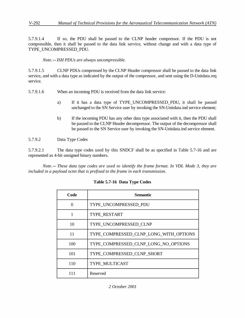
V-292 Manual of Technical Provisions for the Aeronautical Telecommunication Network (ATN)
2 October 2001
5.7.9.1.4 If so, the PDU shall be passed to the CLNP header compressor. If the PDU is notcompressible, then it shall be passed to the data link service, without change and with a data type ofTYPE_UNCOMPRESSED_PDU.
Note.C ISH PDUs are always uncompressible.
5.7.9.1.5 CLNP PDUs compressed by the CLNP Header compressor shall be passed to the data linkservice, and with a data type as indicated by the output of the compressor, and sent using the D-Unitdata.reqservice.
5.7.9.1.6 When an incoming PDU is received from the data link service:
a) If it has a data type of TYPE_UNCOMPRESSED_PDU, it shall be passedunchanged to the SN Service user by invoking the SN-Unitdata.ind service element;
b) If the incoming PDU has any other data type associated with it, then the PDU shallbe passed to the CLNP Header decompressor. The output of the decompressor shallbe passed to the SN Service user by invoking the SN-Unitdata.ind service element.
5.7.9.2 Data Type Codes
5.7.9.2.1 The data type codes used by this SNDCF shall be as specified in Table 5.7-16 and arerepresented as 4-bit unsigned binary numbers.
Note.C These data type codes are used to identify the frame format. In VDL Mode 3, they areincluded in a payload octet that is prefixed to the frame in each transmission.
Table 5.7-16 Data Type Codes
Code Semantic
0 TYPE_UNCOMPRESSED_PDU
1 TYPE_RESTART
10 TYPE_UNCOMPRESSED_CLNP
11 TYPE_COMPRESSED_CLNP_LONG_WITH_OPTIONS
100 TYPE_COMPRESSED_CLNP_LONG_NO_OPTIONS
101 TYPE_COMPRESSED_CLNP_SHORT
110 TYPE_MULTICAST
111 Reserved

Internet communications service V-293
2 October 2001
Bit 8 7 6 5 4 3 2 1Octet 0 Payload Compression Type
Octet 1 Q Index Number
QOS PrioritySecurity
S E M T H O L D (Bit Field)Lifetime (H)
Data Unit Identifier (S)
Segment Offset(O)
Total Length (L)
Discard Reason (D - ER)Octet n (Error PDU only)
Octet n+1 Options length
Octet n+2... Options
Octet p
1000 - 1111 Reserved
5.7.9.3 Compressed CLNP Header Format
5.7.9.3.1 The format of the compressed CLNP Header shall be as shown in Figure 5.7-20.
Figure 5.7-20 Compressed CLNP Header Format
Note 1.CDepending on the data type and the value of the S, O, L and D bits, not all indicated fieldsare present.
Note 2.C The payload field is not formally part of the compressed header and is shown here toillustrate how the data type information is passed when VDL Mode 3 is used as the data link. Other data linksusing this specification can adopt the same approach but may also define a different scheme to convey thedata type information. In VDL Mode 3, the high order 4 bits of the payload field are always set to binary0001 for data originated by this SNDCF.
5.7.9.3.2 A data type of TYPE_COMPRESSED_CLNP_SHORT or TYPE_MULTICAST shallidentify a compressed CLNP Header comprising header fields up to and including the Security field. Such apacket shall contain the Q field, Index Number, QOS, Priority and Security fields. The compressed PDU shallbe a compressed CLNP Data PDU.
5.7.9.3.3 A data type of TYPE_COMPRESSED_CLNP_LONG_NO_OPTIONS shall identify acompressed CLNP Header comprising header fields as illustrated in Figure 5.7-20 excluding the OptionsLength and Options fields.

V-294 Manual of Technical Provisions for the Aeronautical Telecommunication Network (ATN)
2 October 2001
5.7.9.3.3.1 Additionally:
a) If the S-bit is set to a binary 1, then theDUI field shall be present;
b) If the O-bit is set to a binary 1, then theSegment Offsetfield shall be present;
c) If the L-bit is set to a binary 1, then theTotal Lengthfield shall be present;
d) If the H-bit is set to a binary 1, then theLifetimefield shall be present;
e) If the value of the D-bit is set to a binary 1, then theDiscard Reasonfield shall bepresent.
5.7.9.3.4 A data type of TYPE_COMPRESSED_CLNP_LONG_WITH_OPTIONS shall identify aCLNP Header comprising the same header fields as for a data type of TYPE_COMPRESSED_CLNP_LONG_NO_OPTIONS.
5.7.9.3.4.1 Additionally, the compressed CLNP header shall be followed by one or more CLNP optionsfields copied from the original CLNP header.
5.7.9.3.4.2 The total number of bytes occupied by these options fields shall be given by the value of theOptions Length field.
Note.C A data type of TYPE_RESTART implies an empty packet follows and is used as an errorrecovery mechanism. A data type of TYPE_UNCOMPRESSED_CLNP is used when compression indexes arebeing defined; the packet has an uncompressed CLNP header.
5.7.9.3.5 The semantics of the compressed CLNP header fields shall be:
a) The single bit Q-field shall indicate the presence of QoS information. If not set(Q=0), no QoS information is present and the value of the QoS field is undefined;
b) The index number shall be indicate the source and destination NSAP Addressespresent in the original CLNP Header. The index number shall be in the range 0 to127 (decimal);
c) The QoS-field shall consist of the CE (bit 8), T/C (bit 7), E/T (bit 6), and E/C (bit 5)bits respectively of the ISO/IEC 8473 QoS Maintenance Parameter;
Note.C The sequencing vs. transit delay (S/T) bit is sent in the T-field (see Figure 5.7-20). Thisimplies that whenever the S/T-bit is set to 1, a long compression format has to be used.
d) The Priority field shall be a 4-bit unsigned binary number representing a priority inthe range 0 to 14 decimal. A value of 15 decimal shall imply that no priority has beenspecified;

Internet communications service V-295
2 October 2001
Note.C A CLNP PDU with a higher priority than 15 is compressed by including the priorityparameter itself in the compressed header.
e) The Security field shall be subdivided into two fields and shall indicate the securityparameter of an ATN CLNP packet:
1) The 5 high order bits shall comprise the 5 low order bits of the traffic typesecurity tag of the CLNP security options parameter, and
2) The low order 3 bits shall comprise the 3 low order bits of the securityclassification tag of the CLNP security options parameter.
A zero value of either or both of the above two fields shall imply that the correspondingsecurity tag is not present in the CLNP Header;
Note.C The traffic type is implicitly ATSC which implies that a CLNP PDU containing any othertraffic type (e.g. AOC) is compressed by including the security parameter itself in the compressed header.
f) The bit field comprising the S, E, M, T, H, O, L and D-bits, shall have the followingsemantics:
Bit Semantic (Present = 1)
S SP flag of CLNP Header - Data Unit Identifier present
E Complement of CLNP ER flag
M MS-bit of CLNP Header
T Sequence vs. Transit Delay Bit (from QoS option)
H Lifetime Field present (Hop Count)
O Segment Offset present
L Total Length Field present
D Type of PDU (Error = 1, Data = 0)
g) The presence of the Lifetime field shall be indicated by the H bit being set to 1. Theabsence of the Lifetime field shall imply a value for downlink PDUs of decimal 29,and for uplink PDUs, a value of decimal 5;
h) The presence of the Data Unit Identifier field shall be indicated by the S-bit being setto 1. The Data Unit Identifier shall always be present for segmented packets orwhenever the SP-bit is set. Absence of this field shall imply that segmentation is notpermitted;

V-296 Manual of Technical Provisions for the Aeronautical Telecommunication Network (ATN)
2 October 2001
i) The presence of the Segment Offset field shall be indicated by the O-bit being set to1. The Segment Offset shall be sent whenever the SP-bit is set and the Segment Offsetis greater than zero. Absence of this field shall imply a value of zero;
j) The presence of the Total Length field shall be indicated by the L bit being set to 1.The Total Length field shall be present the first time a PDU fragment a given DUI issent only;
Note.C This implies that the value of the field is cached by the receiver by DUI and subsequentfragments with the same DUI are decompressed using the cached total length value.
k) The presence of the Discard Reason field shall be indicated by the D-bit being set to1. It shall contain the value of the Discard Reason options parameter field;
l) An Options Length field shall contain as its value the number of bytes occupied bythe Options field;
m) The value of the Options field shall comprise one or more CLNP options parameters.
5.7.9.4 Data Transmission Procedures
5.7.9.4.1 Determination of whether an NPDU is compressible
5.7.9.4.1.1 An NPDU received as user data of an SN-UnitData.req shall be compressible if and only if:
a) the Network Layer Protocol Identifier is binary 1000 0001 (i.e. it is a CLNP NPDU),and
b) the CLNP version/protocol id extension is set to binary 0000 0001, and
c) the PDU Type is for a Data or Error PDU.
5.7.9.4.1.2 If the NPDU is not compressible, then it shall be passed unchanged to the data link service fortransmission, indicating a data type of TYPE_UNCOMPRESSED_PDU.
5.7.9.4.2 Assignment of a Compression Index
5.7.9.4.2.1 The CLNP header compressor shall maintain a local compression directory with up to 128entries relating an index number in the range 0 to 127, to Source and Destination NSAP Addresses.
5.7.9.4.2.2 Recommendation.CA separate 128 entry directory and index number series should be usedfor each peer system with which the sending system is in contact.
5.7.9.4.2.3 When a compressible NPDU has been submitted for transmission, this directory shall beinterrogated in order to locate an entry corresponding to the Source and Destination NSAP Addresses of theNPDU.

Internet communications service V-297
2 October 2001
5.7.9.4.2.4 If such an entry is located, the associated index number shall be retrieved and the proceduresspecified in 5.7.9.4.3 shall be followed.
5.7.9.4.2.5 Otherwise, an unassigned index number shall be obtained and a local compression directoryentry created associating this index number with the NPDU’s Source and Destination NSAP Addresses.
5.7.9.4.2.6 TheNetworkLayer Protocol Identifier shall bereplacedbytheassigned index number encodedas an unsigned 8-bit binary number, and the NPDU passed unchanged to the data link service for transmission,indicating a data type of TYPE_UNCOMPRESSED_CLNP.
5.7.9.4.2.7 If there are no unassigned index numbers available, the NPDU shall be passed otherwiseunchangedto thedata linkservicefor transmission, indicatinga data typeof TYPE_UNCOMPRESSED_PDU.
5.7.9.4.3 Creation of the Compressed Header
5.7.9.4.3.1 The CLNP PDU Header including theNetworkLayer Protocol Identifier shall be removed andreplaced with a compressed header in the format illustrated inFigure5.7-20 applying thefollowingprocedures:
a) The Index Number field shall be set to the value of the assigned index numberencoded as a 7-bit unsigned binary number;
b) The Q-bit shall be set to 1 if a Globally Unique QoS Maintenance Parameter ispresent in the original CLNP Header and the QoS field bits and T-bit set accordingto the value of the Globally Unique QoS Maintenance Parameter and 5.7.9.3. The Q-bit shall be set to 0 otherwise;
c) If a Priority options parameter is present in the original CLNP Header and the priorityvalue is 14 or less then the Priority field shall be set to the low order 4 bits of thePriority options parameter. The Priority field shall be set to zeroes otherwise;
d) If a Security Options parameter is present in the original CLNP Header and the valueof the parameter is:
1) an ATN Security Label, and
2) the Traffic Type and Security Classification security tags are the onlysecurity tags present, and
3) the Traffic Type is ATSC, then
the value of the Security Field shall be set using the value of the Security OptionsParameter and according to 5.7.9.3. Otherwise the Security Field shall be set tozeroes;

V-298 Manual of Technical Provisions for the Aeronautical Telecommunication Network (ATN)
2 October 2001
e) If the PDU is an Error PDU then the D-bit shall be set to 1. Otherwise the D-bit shallbe set to 0;
f) The E-bit shall be set to the complement of the E/R flag in the original CLNP Header;
g) If the value of the Lifetime given in the original CLNP Header is greater than 5 or lessthan 29 (decimal), then a Lifetime field shall be included in the compressed headerand the H bit set to 1. Otherwise the H bit is set to zero. The Lifetime field value shallbe identical to the value given in the original CLNP Header;
h) If the SP flag in the original CLNP Header is non-zero, then a Data Unit Identifier(DUI) field shall be present and the S-bit set to 1, and:
1) The M-bit shall be set to the value of the MS-bit in the original CLNPHeader;
2) The value of the DUI field shall be set to the Data Unit Identifier containedin the original CLNP Header;
3) If a non-zero Segment offset is present in the original CLNP Header then theO-bit shall be set to 1 and a Segment Offset field shall be present. The valueof the Segment Offset field shall be set to the value of the Segment Offset inthe original CLNP Header. Otherwise the O-bit shall be zero;
4) If this is the first time that a packet with this DUI has been sent since theindex number was assigned, then the L-bit shall be set to 1 and a TotalLength Field shall be included and set to the value of the Total Length givenin the original CLNP Header. Otherwise the L-bit shall be set to zero.
Otherwise the S and M bits shall be set to zero;
Note 1.C It is not an error to include a Total Length field in more than one compressed header withthe same DUI.
Note 2.C This implies caching by the receiver of the value of the Total Length field. The cachedinformation need not be kept longer than the indicated PDUlifetime, and is discarded anyway when theassociated index becomes unassigned.
i) If the original CLNP PDU is an Error PDU then the Discard Reason field shall bepresent and set to the value of the Reason for Discard given in the original CLNPHeader;
j) If the original CLNP Header contains:
1) a priority parameter value greater than 14,

Internet communications service V-299
2 October 2001
2) a security parameter that was uncompressible, i.e. the value of the securityfield is zero, or
3) any other options parameters other than padding and a Globally Unique QoSMaintenance Parameter, then
such options parameters shall be copied to the compressed header. The OptionsLength field shall be present and set to the number of bytes in the copied parameters.Otherwise neither the Options Length nor Options shall be present.
5.7.9.4.3.2 Thecompressedheader createdaboveshall replacetheoriginal CLNP Header andtheresultingcompressed header and user data shall be passed to the data link service for transmission. The data type shallbe:
a) TYPE_COMPRESSED_CLNP_LONG_WITH_OPTIONS, if options parametershave been copied into the compressed header;
b) TYPE_COMPRESSED_CLNP_LONG_NO_OPTIONS, if no options parametershave been copied into the compressed header and the compressed header has a non-zero Bit Field;
c) TYPE_COMPRESSED_CLNP_SHORT otherwise, when the Bit Field shall not beincluded in the compressed header for this datatype i.e. it is implicitly zero in this datatype.
Note.C A zero Bit Field implies that no further fields follow this field as they are all dependent onthe Bit Field being non-zero.
5.7.9.4.4 Compression Index Lifetime
5.7.9.4.4.1 For each assigned index number, a timer (CT3) shall be associated.
5.7.9.4.4.2 This timer shall be (re)started every time a packet is sent with that index number.
5.7.9.4.4.3 When the timer expires, the index shall become unassigned.
5.7.9.4.4.4 When an underlying data link is terminated, all associated index numbers become unassigned.
5.7.9.4.4.5 When an index number becomes unassigned, the corresponding local compression directoryentry shall be removed.
5.7.9.5 Data Reception Procedures
5.7.9.5.1 Handling of an Incoming Packet
5.7.9.5.1.1 When an incoming packet is recevied from the data link service the indicated data type shallbe determined and:

V-300 Manual of Technical Provisions for the Aeronautical Telecommunication Network (ATN)
2 October 2001
a) If the data type is TYPE_UNCOMPRESSED_PDU, the received packet shall bepassed unchanged to the SN Service user using the SN-Unitdata.ind service element;
b) If the data type is TYPE_UNCOMPRESSED_CLNP then the procedures specifiedin 5.7.9.5.2 shall be applied;
c) If the data type is TYPE_RESTART the procedures specified in 5.7.9.5.6 shall beapplied;
d) Otherwise the decompression procedures specified in 5.7.9.5.3 shall be applied.
Note.C TYPE_MULTICAST packets are specified in 5.7.9.6.
5.7.9.5.2 Index Number Assignment
5.7.9.5.2.1 When an incoming packet is received with a data type of TYPE_UNCOMPRESSED_CLNP,the first octet (an unsigned binary number) shall be decoded as the new index number and replaced by theNetwork Layer Identifier Octet for CLNP (binary 1000 0001).
5.7.9.5.2.2 The PDU shall be passed otherwise unchanged to the SN Service user using the SN-Unitdata.ind service element.
5.7.9.5.2.3 The decompressor shall maintain a local decompression directory for each peer system withwhich it is currently in communication.
5.7.9.5.2.4 This directory shall comprise a maximum of 128 entries relating an index number in the range0 to 127, to Source and Destination NSAP Addresses.
5.7.9.5.2.5 This directory shall be interrogated to determine if an entry already exists for this indexnumber.
5.7.9.5.2.6 If such an entry exists and identifies the same Source and Destination NSAP Address pair asencoded into the header of the incoming packet, then no further action shall be taken.
5.7.9.5.2.7 If a different Source and Destination NSAP Address pair is found then the error recoveryprocedures specified in 5.7.9.5.4 shall be followed.
5.7.9.5.2.8 Otherwise, a newdecompressiondirectoryentryshall becreatedassociating the received indexnumber with the Source and Destination NSAP Address pair encoded into the header of the incoming packet.
5.7.9.5.3 Decompression Procedures
5.7.9.5.3.1 When an incoming packet is received, then, with reference to the compressed header formatgiven in Figure 5.7-20, a CLNP Header shall be constructed as follows:

Internet communications service V-301
2 October 2001
a) The Network Layer Protocol Identifier shall be set to binary 1000 0001;
b) The Version/Protocol ID Extension shall be set to binary 0000 0001;
c) The index number shall be decoded fromthecompressedheader andusedto determinethe Source and Destination NSAP Addresses to be used in the reconstructed CLNPHeader by interrogating the local directory specified in 5.7.9.5.2. If no correspondingdirectory entry can be found then the incoming packet shall be discarded and the errorrecovery procedures specified in 5.7.9.5.4 shall be applied;
d) If the Q-bit is non-zero, a Globally Unique QoS parameter shall be added to theCLNP Header options parameters and the QoS field bits used to determine thecorresponding bits in the parameter value, as specified in 5.7.9.3;
e) If the priority field is non-zero, a priority parameter shall be added to the CLNPHeader options parameters and the decimal value of the priority field shall be encodedas the value of the priority parameter;
f) If the security field is non-zero, then a globally unique security parameter shall beadded to the CLNP Header, indicating an ATN Security Label:
1) If the most significant 5 bits of the security field are non-zero, then a TrafficType security tag shall be included in the ATN Security Label; the mostsignificant 3 bits shall indicate a traffic type of ATSC and the leastsignificant 5 bits shall be copied from the most significant 5 bits of thesecurity field;
2) If the least significant 3 bits of the security field are non-zero, then a securityclassification security tag shall be included in the ATN Security Label; thevalue of this tag shall be the encoded decimal value of the least significant 3bits of the security field.
Note.C A padding options parameter may also be included in the CLNP Header.
5.7.9.5.3.2 Decompression of Short Compressed Headers
5.7.9.5.3.2.1 When the data type of the received packet is TYPE_COMPRESSED_CLNP_SHORT, theCLNP Header shall be constructed as above, and:
a) The PDU Type shall be set to indicate a Data PDU;
b) The E/R flag shall be set to 1;
c) The MS and SP flags shall be set to 0, and no segmentation part included in thereconstructed CLNP Header;

V-302 Manual of Technical Provisions for the Aeronautical Telecommunication Network (ATN)
2 October 2001
d) The Lifetime shall be encoded as decimal 5 if the receiving system is airborne, or asdecimal 29 otherwise;
e) The Length Indicator field shall be set to the length of the reconstructed header;
f) The reconstructed header shall replace the compressed header and value of theSegment Length shall be set to the total length to the PDU.
5.7.9.5.3.2.2 The checksum for the reconstructed header shall be recomputed and stored within it.
5.7.9.5.3.2.3 The resulting PDU shall be passed to the SN Service user using the SN-Unitdata.ind serviceelement.
5.7.9.5.3.3 Decompression of Long Compressed Headers with no Options
5.7.9.5.3.3.1 When the data type of the received packet is TYPE_COMPRESSED_CLNP_LONG_NO_OPTIONS, then the CLNP Header shall be constructed as above in 5.7.9.5.3.
5.7.9.5.3.3.2 The Bit Field shall also be present and used to determine the further additional information inthe reconstructed CLNP Header according to the following procedures:
a) If the D-bit is set to 1, then the PDU Type shall be set to indicate an Error PDU.Otherwise the PDU Type shall be set to indicate a Data PDU;
b) The E/R flag shall be set to the complement of the E-bit;
c) If the Q-bit is set, then the value of the S/T-bit in the globally unique QoSMaintenance Parameter shall be set to the value of the T-bit;
d) If the H-bit is set, then the Lifetime in the reconstructed CLNP header shall be set tothe value of the Lifetime field in the compressed CLNP Header. If the H-bit is zero,the Lifetime shall be encoded as decimal 5 if the receiving system is airborne, or asdecimal 29 otherwise;
e) If the S-bit is set to 0, then the SP and MS flags shall be set to zero and nosegmentationpart included in the reconstructed CLNP Header. Otherwise, theSP flagshall be set to 1 and a segmentation part included:
1) The MS flag shall be set to the value of the M-bit;
2) The Data Unit Identifier shall be copied from the compressed header to thereconstructed header;
3) If the O-bit is zero, then the Segment Offset shall be set to zero. Otherwisethe Segment Offset value shall be copied from the compressed header to thereconstructed header;

Internet communications service V-303
2 October 2001
4) If the L-bit is set to 1, then the Total Length value shall be copied from thecompressed header to the reconstructed header. Additionally:
i. The Total Length shall be cached for use with later packets with thesame DUI and index number, and from the same peer system;
ii. If a Total Length with the same DUI and index number, and fromthe same peer system had already been cached and was a differentvalue, then the PDU shall be discarded and the procedures in5.7.9.5.4 followed.
5) If the L-bit is set to zero, then the decompressor shall attempt to find acached Total Length for the same DUI, index number and peer system:
i. If found, then this Total Length shall be copied into thereconstructed CLNP Header;
ii. If not found, then the PDU shall be discarded.
6) Recommendation.C The error recovery procedures specified in 5.7.9.5.4should be followed following the PDU discard.
Note.CCached Total Lengths may be discarded when the PDU’s lifetime has expired, the indexnumber becomes unassigned, or the data link with the peer system terminated.
f) The Length Indicator field shall be set to the length of the reconstructed header;
g) The reconstructed header shall replace the compressed header and value of theSegment Length shall be set to the total length to the PDU;
h) The checksum for the reconstructed header shall be recomputed and stored within it.
5.7.9.5.3.3.3 The resulting PDU shall be passed to the SN Service user using the SN-Unitdata.ind serviceelement.
5.7.9.5.3.4 Decompression of Long Compressed Headers with Options
5.7.9.5.3.4.1 When the data type of the received packet is TYPE_COMPRESSED_CLNP_LONG_WITH_OPTIONS, the CLNP Header shall be reconstructed as specified in 5.7.9.5.3.3 above.
5.7.9.5.3.4.2 Additionally, the options parameters contained in the compressed header shall be copied to thereconstructed CLNP Header prior to the recomputation of the Length Indication, Segment Offset andChecksum.
5.7.9.5.4 Error Recovery Procedures
V-304 Manual of Technical Provisions for the Aeronautical Telecommunication Network (ATN)
2 October 2001
5.7.9.5.4.1 In order to perform error recovery, an empty packet with a data type of TYPE_RESTARTshall be sent to the peer system, and the local decompression directory associated with packets received fromthat peer system shall be cleared i.e. all entries removed.
5.7.9.5.4.2 Received compressed packets shall be discarded but otherwise ignored until a packet isreceived with a data type of TYPE_UNCOMPRESSED_CLNP.
5.7.9.5.4.3 This shall implicitly acknowledge the restart.
Note.C It is possible to confuse a TYPE_UNCOMPRESSED_CLNP that was sent by the peer systemto create a new local reference with a TYPE_UNCOMPRESSED_CLNP sent after re-initialisation of thecompression dictionary. However, this will resolve itself following the detection of consequential errors anda further error recovery procedure.
5.7.9.5.5 Index Number Refresh
5.7.9.5.5.1 Whenever a valid packet is received with a given index number, a timer (CT3) shall be(re)started.
5.7.9.5.5.2 When this timer expires the local decompression directory entry for the associated indexnumber shall be removed.
5.7.9.5.6 Processing a TYPE_RESTART Packet
5.7.9.5.6.1 When a TYPE_RESTART packet is received, the local compression directory entriesassociated when the sending peer system shall be removed.
5.7.9.5.6.2 The associated index numbers shall become unassigned.
5.7.9.6 Multicasting
5.7.9.6.1 TheTYPE_MULTICAST data typeshall identifya TYPE_CLNP_COMPRESSED_SHORTformat packet that is sent multicast to more than one destination NSAP.
Note 1.C An example of the use of TYPE_MULTICAST is a weather broadcast having a destinationNSAP which indicates all hosts who want weather information, and a source NSAP indicating that the dataoriginates from a CAA weather processor.
Note 2.CMulticast index numbers may be predefined or dynamically defined. The means to predefinemulticast NSAP Addresses and associated index numbers is a local matter and outside the scope of thisspecification.
5.7.9.6.2 A PDU with a multicast destination NSAP Address that cannot be compressed into the aboveformat shall be sent as TYPE_UNCOMPRESSED_PDU.

Internet communications service V-305
2 October 2001
5.7.9.6.3 When a ground station uses predefined index numbers, the index numbers used forTYPE_MULTICAST compressed packets shall correspond to a specified and well known Source NSAPAddress and Destination Multicast NSAP Address.
5.7.9.6.4 This correspondence shall be known to ground station and all aircraft able to receive thetransmission.
5.7.9.6.5 Dynamic Assignment of Index Numbers
5.7.9.6.5.1 When index numbers are dynamically assigned then index numbers shall be assigned andmaintained as for singlecast communications
Note.C For example, when a ground station uses dynamically assigned index numbers, theTYPE_UNCOMPRESSED_CLNP packet format is used to assign the meaning of index numbers as specifiedin 5.7.9.4.2.
5.7.9.6.5.2 Recommendation.CWhen assigning index numbers to multicast destinations, the groundstation should use a different series of index numbers to those used for single cast communications.
5.7.9.6.5.3 An airborne system shall use a separate local decompression directory for multicast indexnumbers to that used for singlecast index numbers, and for each ground station.
5.7.9.6.5.4 Whena data link is terminated, the index numbers associatedwith thepeer systemfor multicastcommunications shall become unassigned.
5.7.9.6.5.5 When a TYPE_UNCOMPRESSED_CLNP packet is sent with a dynamically assigned indexnumber for multicast communications, timers CT1 and CT2 shall be (re)started.
5.7.9.6.5.6 When the CT1 timer expires, the next PDU sent using this index number shall be sent in theTYPE_UNCOMPRESSED_CLNP format even if it is otherwise compressible as a TYPE_MULTICAST.
Note.C The purpose of this procedure is to ensure that aircraft that have recently joined the networkhave an upper bound on the length of time they are unable to decompress such PDUs.
5.7.9.6.5.7 When the CT2 timer expires, the associated index number shall become unassigned.
5.7.9.6.6 Compression of Multicast PDUs
5.7.9.6.6.1 If a PDU with a multicast Destination NSAP Address is:
a) compressible according to 5.7.9.4.1,
b) may be compressed into the TYPE_COMPRESSED_SHORT format,
c) a suitable index number has been assigned, and
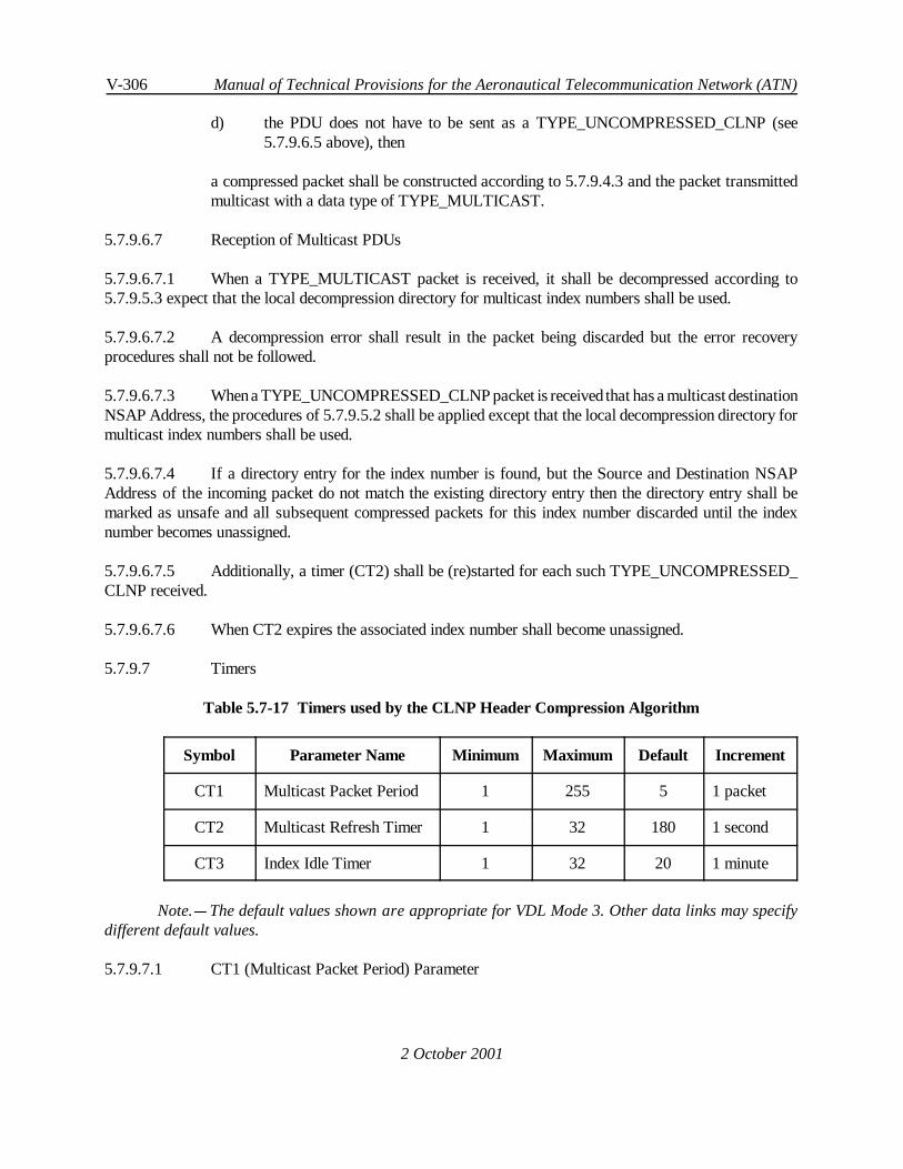
V-306 Manual of Technical Provisions for the Aeronautical Telecommunication Network (ATN)
2 October 2001
d) the PDU does not have to be sent as a TYPE_UNCOMPRESSED_CLNP (see5.7.9.6.5 above), then
a compressed packet shall be constructed according to 5.7.9.4.3 and the packet transmittedmulticast with a data type of TYPE_MULTICAST.
5.7.9.6.7 Reception of Multicast PDUs
5.7.9.6.7.1 When a TYPE_MULTICAST packet is received, it shall be decompressed according to5.7.9.5.3 expect that the local decompression directory for multicast index numbers shall be used.
5.7.9.6.7.2 A decompression error shall result in the packet being discarded but the error recoveryprocedures shall not be followed.
5.7.9.6.7.3 Whena TYPE_UNCOMPRESSED_CLNP packet is receivedthat has a multicast destinationNSAP Address, the procedures of 5.7.9.5.2 shall be applied except that the local decompression directory formulticast index numbers shall be used.
5.7.9.6.7.4 If a directory entry for the index number is found, but the Source and Destination NSAPAddress of the incoming packet do not match the existing directory entry then the directory entry shall bemarked as unsafe and all subsequent compressed packets for this index number discarded until the indexnumber becomes unassigned.
5.7.9.6.7.5 Additionally, a timer (CT2) shall be (re)started for each such TYPE_UNCOMPRESSED_CLNP received.
5.7.9.6.7.6 When CT2 expires the associated index number shall become unassigned.
5.7.9.7 Timers
Table 5.7-17 Timers used by the CLNP Header Compression Algorithm
Symbol Parameter Name Minimum Maximum Default Increment
CT1 Multicast Packet Period 1 255 5 1 packet
CT2 Multicast Refresh Timer 1 32 180 1 second
CT3 Index Idle Timer 1 32 20 1 minute
Note.C The default values shown are appropriate for VDL Mode 3. Other data links may specifydifferent default values.
5.7.9.7.1 CT1 (Multicast Packet Period) Parameter

Internet communications service V-307
2 October 2001
5.7.9.7.1.1 The Multicast Packet Period shall define the period whereby an uncompressed packet is sentto refresh the compressor state for the receiving unit.
5.7.9.7.1.2 Recommendation.CWhen the underlying data link uses XID messages to configure the datalink and set parameter values, the XID format for CT1 should be:
Parameter ID 0 1 0 1 0 0 1 0 Multicast Packet Period
Parameter Length 0 0 0 0 0 0 0 1
Parameter Value v8 v7 v6 v5 v4 v3 v2 v1
5.7.9.7.2 CT2 (Multicast Refresh) Timer
5.7.9.7.2.1 The Multicast Refresh Timer shall define an upper bound on the time between transmissionof uncompressed headers in case message traffic is light.
Note.CThis ensures that the receiver can correlate the header with the compression index in a timelyfashion.
5.7.9.7.2.2 Recommendation.CWhen the underlying data link uses XID messages to configure the datalink and set parameter values, the XID format for CT2 should be:
Parameter ID 0 1 0 1 0 0 1 1 Multicast Refresh Timer
Parameter Length 0 0 0 0 0 0 1 0
Parameter Value v16 v15 v14 v13
v8 v7 v6 v5
v12 v11 v10 v9
v4 v3 v2 v1
5.7.9.7.3 CT3 (Index Idle) Timer
5.7.9.7.3.1 The Index Idle Timer shall define an upper bound on how long the compressor shall waitbefore recovering an idle index.
Note.C An index is assumed idle if no message traffic has passed using it before the CT3 timerexpires.
5.7.9.7.3.2 Recommendation.CWhen the underlying data link uses XID messages to configure the datalink and set parameter values, the XID format for CT3 should be:
Parameter ID 0 1 0 1 0 1 0 0 Index Idle Timer
Parameter Length 0 0 0 0 0 0 1 0

V-308 Manual of Technical Provisions for the Aeronautical Telecommunication Network (ATN)
2 October 2001
Parameter Value v16 v15 v14 v13
v8 v7 v6 v5
v12 v11 v10 v9
v4 v3 v2 v1

Internet communications service V-309
5.8 ROUTING INFORMATION EXCHANGE SPECIFICATION
5.8.1 Introduction
5.8.1.1 Scope
Note.— This chapter provides requirements and recommendations pertaining to the use of theISO/IEC 10747 Inter-Domain Routing Protocol over Air/Ground and Ground/Ground Data Links, and theuse of ISO/IEC 9542 in support of Route Initiation over Air/Ground Data Links. This chapter is concernedwith the interoperability of protocol implementations and provides a compliance statement and APRL foreach of the above protocols. It does not specify how Routing Information exchanged using ISO/IEC 10747is used by Routers when forwarding ISO/IEC 8473 NPDUs, or the application of Routing Policy controllingroute aggregation and re-advertisement of routes. These subjects are covered in 5.3.
5.8.1.2 Applicability of Requirements
5.8.1.2.1 All ATN Airborne Routers, with the exception of ATN Airborne Routers implementing theprocedures for the optional non-use of IDRP, shall comply with the provisions contained in 5.8.2, 5.8.3,5.8.3.2.2 to 5.8.3.2.5 inclusive, 5.8.3.2.8 to 5.8.3.2.9 inclusive, 5.8.3.2.11, 5.8.3.3.2.1, 5.8.3.3.3 and theAPRLs specified for an Airborne Router in 5.8.3.5.
5.8.1.2.2 ATN Airborne Routers implementing the procedures for the optional non-use of IDRP shallbe compliant with 5.8.2.
5.8.1.2.3 All ATN Air/Ground Routers shall comply with the provisions contained in 5.8.2, 5.8.3,5.8.3.2.2 to 5.8.3.2.9 inclusive, 5.8.3.2.11, 5.8.3.3.2.2, 5.8.3.3.3 and the APRLs specified for an Air/GroundRouter in 5.8.3.5.
5.8.1.2.4 All Ground/Ground Inter-Domain Routers shall comply with theprovisions contained in 5.8.2,5.8.3.2.2 to 5.8.3.2.9 inclusive, 5.8.3.2.11, 5.8.3.3.2.2, 5.8.3.3.3 and the APRLs specified for anGround/Ground Router in 5.8.3.5.
5.8.1.2.5 All ATN Routers, with the exception of Airborne Routers implementing the procedures forthe optional non-use of IDRP, shall comply with the provisions contained in 5.8.3.2.10.1.
5.8.1.2.6 All ATN Routers which support ATN security services shall comply with the provisionscontained in 5.8.3.2.10.2.

V-310 Manual of Technical Provisions for the Aeronautical Telecommunication Network (ATN)
2 October 2001
5.8.2 End System to Intermediate System Routing InformationExchange Protocol (ES-IS) over Mobile Subnetworks
5.8.2.1 General
5.8.2.1.1 ATN Airborneand Air/Ground Routers directly connected to a MobileSubnetwork (e.g. ModeS, AMSS or VDL) shall operate ISO/IEC 9542 over each such Mobile Subnetwork.
5.8.2.1.2 Configuration Information shall beexchanged bybothATN Air/Ground and AirborneRoutersover each Mobile Subnetwork connection supporting an adjacency between them.
Note 1.— The use of ISO/IEC 9542 Configuration Information over Mobile Subnetworks in supportof air/ground route initiation is specified in 5.3.5.2.6.
Note 2.— The use of ISO/IEC 9542 Configuration Information over Mobile Subnetworks in supportof IDRP Authentication Type 2 is specified in 5.3.5.2.16.
5.8.2.1.3 ATN Data Link Capabilities Parameter
5.8.2.1.3.1 ATN Air/Ground and Airborne Routers shall include the ATN Data Link CapabilitiesParameter in the options part of each ISO/IEC 9542 ISH PDU which they send over an ATN MobileSubnetwork and evaluate the ATN Data Link Capabilities Parameter on reception.
Note 1.— The ATN Data Link Capabilities Parameter is used to inform the peer ATN Router aboutthe extended capabilities which are supported by the sending ATN Router over the air/ground adjacency andto signal authentication related information. The receiving ATN Router will use this information to invokethose extended capabilities for use over the air/ground adjacency which are supported by both ATN routersforming the air/ground adjacency and provide its public keycertificate, if requested. This procedure supportsbackwards compatibility between ATN routers which may implement different editions of this specification.
Note 2.— The extended capabilities comprise those protocol features and capabilities (e.g. security)which have been added to this specification beyond Edition 1 for use over the air/ground link.
Note 3.— The ATN Data Link Capabilities Parameter has to be sent over the air/ground adjacencyeven if its value field comprises all zeroes.
5.8.2.1.3.2 The ATN Data Link Capabilities Parameter shall not occur more than once in the options partof an ISO/IEC 9542 ISH PDU.
5.8.2.1.3.3 TheATN Data Link Capabilities Parameter shall consist of three fields, as illustrated in Figure5.8-1.
ATN Data Link CapabilitiesParameter Code
ATN Data Link CapabilitiesParameter Length
ATN Data Link CapabilitiesParameter Value
Octet 1 2 3 ...... end
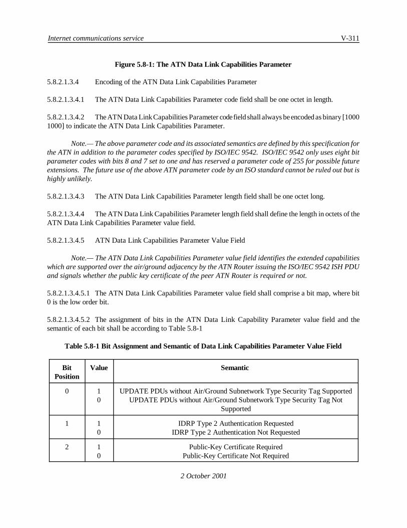
Internet communications service V-311
2 October 2001
Figure 5.8-1: The ATN Data Link Capabilities Parameter
5.8.2.1.3.4 Encoding of the ATN Data Link Capabilities Parameter
5.8.2.1.3.4.1 The ATN Data Link Capabilities Parameter code field shall be one octet in length.
5.8.2.1.3.4.2 TheATN Data Link Capabilities Parameter codefield shall always beencoded as binary [10001000] to indicate the ATN Data Link Capabilities Parameter.
Note.— The above parameter code and its associated semantics are defined by this specification forthe ATN in addition to the parameter codes specified by ISO/IEC 9542. ISO/IEC 9542 only uses eight bitparameter codes with bits 8 and 7 set to one and has reserved a parameter code of 255 for possible futureextensions. The future use of the above ATN parameter code by an ISO standard cannot be ruled out but ishighly unlikely.
5.8.2.1.3.4.3 The ATN Data Link Capabilities Parameter length field shall be one octet long.
5.8.2.1.3.4.4 The ATN Data Link Capabilities Parameter length field shall define the length in octets of theATN Data Link Capabilities Parameter value field.
5.8.2.1.3.4.5 ATN Data Link Capabilities Parameter Value Field
Note.— The ATN Data Link Capabilities Parameter value field identifies the extended capabilitieswhich are supported over the air/ground adjacency by the ATN Router issuing the ISO/IEC 9542 ISH PDUand signals whether the public key certificate of the peer ATN Router is required or not.
5.8.2.1.3.4.5.1 The ATN Data Link Capabilities Parameter value field shall comprise a bit map, where bit0 is the low order bit.
5.8.2.1.3.4.5.2 The assignment of bits in the ATN Data Link Capability Parameter value field and thesemantic of each bit shall be according to Table 5.8-1
Table 5.8-1 Bit Assignment and Semantic of Data Link Capabilities Parameter Value Field
BitPosition
Value Semantic
0 10
UPDATE PDUs without Air/Ground Subnetwork Type Security Tag SupportedUPDATE PDUs without Air/Ground Subnetwork Type Security Tag Not
Supported
1 10
IDRP Type 2 Authentication RequestedIDRP Type 2 Authentication Not Requested
2 10
Public-Key Certificate RequiredPublic-Key Certificate Not Required

V-312 Manual of Technical Provisions for the Aeronautical Telecommunication Network (ATN)
2 October 2001
Note.— By setting bit 0 to one an Airborne Router which supports the use of IDRP for theexchangeof routing information (i.e. a Class 6 Airborne Router) indicates its capability to receive and processUPDATE PDUs without air/ground subnetwork type security tag(s). In this case, the Airborne Router mustbe in a position to use mobile subnetwork-specific information received during air/ground route initiation(see 5.3.5.2.6.7) to update its FIB, Loc_RIB and relevant Adj_RIB-Outs. By setting bit 0 to one anAir/Ground Router indicates its capability to generate and forward UPDATE PDUs without air/groundsubnetwork type security tag(s) across the mobile adjacency.
5.8.2.1.3.4.5.3 The remaining bits of the ATN Data Link Capabilities Parameter value field are reserved forfuture use by this specification and shall be set to zero by the sending ATN Router and ignored on reception.
5.8.2.1.3.5 When an ATN Air/Ground or Airborne Router recognises an ATN Data Link CapabilitiesParameter in a received ISO/IEC 9542 ISH PDU, then it shall determine from the parameter value field theextended capabilities supported by the sending ATN Router.
Note.— Backwards compatibility is a goal of all editions of this specification and this mechanismis used to determine whether features defined in later editions of this specification can be used incommunications with the remote ATN systems.
5.8.2.1.3.6 The receiving ATN Router having determined the extended capabilities of the sending ATNRouter shall invoke and use in further communications with this ATN Router only those extended capabilitieswhich are supported by both ATN Routers.
5.8.2.1.4 Mobile Subnetwork Capabilities Parameter
5.8.2.1.4.1 ATN Air/Ground and Airborne Routers shall support the Mobile Subnetwork CapabilitiesParameter in the options part of an ISO/IEC 9542 ISH PDU.
5.8.2.1.4.2 The Mobile Subnetwork Capabilities Parameter shall be used in the ATN to conveyinformation about the ATSC Class and the traffic type(s) supported by an ATN Mobile Subnetwork.
5.8.2.1.4.3 The Mobile Subnetwork Capabilities Parameter shall consist of three fields, as illustrated inFigure 5.8-2, and shall not occur more than once in the options part of an ISO/IEC 9542 ISH PDU.
Subnetwork CapabilitiesParameter Code
Subnetwork CapabilitiesParameter Length
Subnetwork CapabilitiesParameter Value
Octet 1 2 3 ... 4
Figure 5.8-2: The Mobile Subnetwork Capabilities Parameter
5.8.2.1.4.4 Encoding of the Mobile Subnetwork Capabilities Parameter
5.8.2.1.4.4.1 TheMobileSubnetwork Capabilities Parameter code field shall beoneoctet in length and shallalways be encoded as binary [1000 0001] to indicate the Mobile Subnetwork Capabilities Parameter.

Internet communications service V-313
2 October 2001
Note.— The above parameter code and its associated semantics are defined by this specification forthe ATN in addition to the parameter codes specified by ISO/IEC 9542. ISO/IEC 9542 only uses eight bitparameter codes with bits 8 and 7 set to one and has reserved a parameter code of 255 for possible futureextensions. The future use of the above ATN parameter code by an ISO standard cannot be ruled out but ishighly unlikely.
5.8.2.1.4.4.2 The Mobile Subnetwork Capabilities Parameter length field shall be one octet long and shalldefine the length in octets of the Mobile Subnetwork Capabilities Parameter value field.
5.8.2.1.4.4.3 Mobile Subnetwork Capabilities Parameter Value Field
5.8.2.1.4.4.3.1 The first octet of this field shall indicate the traffic type(s) allowed to pass over theAir/GroundSubnetwork over which the ISO/IEC 9542 ISH PDU is exchanged.
5.8.2.1.4.4.3.2 This octet shall comprise a bit map, where each bit corresponds to a different traffic type.
5.8.2.1.4.4.3.3 The assignment of bits to traffic types shall be according to Table 5.8-5, where bit 0 is the loworder bit.
5.8.2.1.4.4.3.4 Setting a bit to one shall indicate that the corresponding traffic type is allowed to pass overthe air/ground subnetwork.
5.8.2.1.4.4.3.5 The semantics of bits 5 to 7 shall be reserved for future use and shall always be set to one.
Note 1.— A value of FFh is used to imply no restrictions.
Note 2.— The first octet of the Mobile Subnetwork Capabilities Parameter Value field has the sameencoding and semantics as the second octet of the Air/Ground Subnetwork type security Tag Set of the IDRPSecurity Path Attribute which is defined in 5.8.3.2.3.2.4 through 5.8.3.2.3.2.6.
5.8.2.1.4.4.3.6 If bit 0 of the first octet of the Mobile Subnetwork Capabilities Parameter Value field is setto one, then this field shall contain a second octet which defines the ATSC Class supported by that Air/GroundSubnetwork.
Note.— Bit 0 of the first octet set to one indicates that the Air/Ground Subnetwork is available to theATN Operational Communications traffic type - Air Traffic Service Communications traffic category.
5.8.2.1.4.4.3.7 If present, the second octet of the Mobile Subnetwork Capabilities Parameter Value field shallbe encoded according to Table 5.8-2.
Table 5.8-2: Encoding of Supported ATSC Class
Value ATSC Class
0000 0001 A
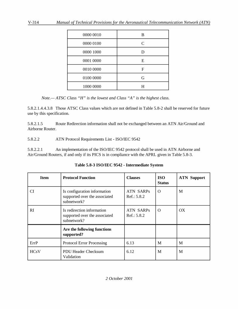
V-314 Manual of Technical Provisions for the Aeronautical Telecommunication Network (ATN)
2 October 2001
0000 0010 B
0000 0100 C
0000 1000 D
0001 0000 E
0010 0000 F
0100 0000 G
1000 0000 H
Note.— ATSC Class “H” is the lowest and Class “A” is the highest class.
5.8.2.1.4.4.3.8 Those ATSC Class values which are not defined in Table 5.8-2 shall be reserved for futureuse by this specification.
5.8.2.1.5 Route Redirection information shall not be exchanged between an ATN Air/Ground andAirborne Router.
5.8.2.2 ATN Protocol Requirements List - ISO/IEC 9542
5.8.2.2.1 An implementation of the ISO/IEC 9542 protocol shall be used in ATN Airborne andAir/Ground Routers, if and only if its PICS is in compliance with the APRL given in Table 5.8-3.
Table 5.8-3 ISO/IEC 9542 - Intermediate System
Item Protocol Function Clauses ISOStatus
ATN Support
CI Is configuration informationsupported over the associatedsubnetwork?
ATN SARPsRef.: 5.8.2
O M
RI Is redirection informationsupported over the associatedsubnetwork?
ATN SARPsRef.: 5.8.2
O OX
Are the following functionssupported?
ErrP Protocol Error Processing 6.13 M M
HCsV PDU Header ChecksumValidation
6.12 M M

Internet communications service V-315
Item Protocol Function Clauses ISOStatus
ATN Support
2 October 2001
HCsG PDU Header ChecksumGeneration
6.12 O O
RpCf Report Configuration 6.2, 6.2.2 CI:M M
RcCf Record Configuration 6.3, 6.3.1 CI:M M
FlCf Flush Old Configuration 6.4 CI:M M
RqRd Request Redirect 6.8 RI:M OX
CfNt Configuration Notification 6.7 CI:O OX
CTGn ESCT Generation 6.3.2 CI:O OX
AMGn Address Mask (only) generation 6.8 RI:O OX
SMGn Address mask and SNPA Maskgeneration
6.8 RI:O OX
Are the following PDUsSupported?
ESH-r <r> End System Hello 7.1, 7.5 CI:M O
ISH-r <r> Intermediate System Hello 7.1, 7.6 CI:M M
ISH-s <s> Intermediate System Hello 7.1, 7.6 CI:M M
RD-s <s> Redirect 7.1, 7.7 RI:M OX
RD-r <r> (ignore) Redirect 6.9, 7.1, 7.7 M M
Are the following PDU fieldssupported?
FxPt <s> Fixed Part<r> Fixed Part
7.2.1, 7.2.77.2.1, 7.2.7
MM
MM
SA-r <r> Source Address, one or moreNSAPs
7.3.1/2/3 CI:M M
NET-s <s> Network Entity Title 7.3.1/2/4 M M
NET-r <r> Network Entity Title 7.3.1/2/4 ISH-r:M ISH-r:M
DA-s <s> Destination Address 7.3.1/2/5 RI:M OX
BSNPA-s <s> Subnetwork Address 7.3.1/2/6 RI:M OX
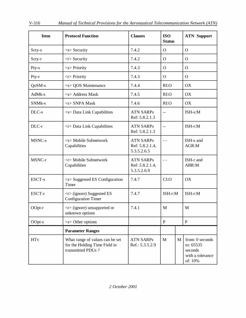
V-316 Manual of Technical Provisions for the Aeronautical Telecommunication Network (ATN)
Item Protocol Function Clauses ISOStatus
ATN Support
2 October 2001
Scty-s <s> Security 7.4.2 O O
Scty-r <r> Security 7.4.2 O O
Pty-s <s> Priority 7.4.3 O O
Pty-r <r> Priority 7.4.3 O O
QoSM-s <s> QOS Maintenance 7.4.4 RI:O OX
AdMk-s <s> Address Mask 7.4.5 RI:O OX
SNMk-s <s> SNPA Mask 7.4.6 RI:O OX
DLC-s <s> Data Link Capabilities ATN SARPsRef: 5.8.2.1.3
-- ISH-s:M
DLC-r <r> Data Link Capabilities ATN SARPsRef: 5.8.2.1.3
-- ISH-r:M
MSNC-s <s> Mobile SubnetworkCapabilities
ATN SARPsRef: 5.8.2.1.4,5.3.5.2.6.5
- - ISH-s andAGR:M
MSNC-r <r> Mobile SubnetworkCapabilities
ATN SARPsRef: 5.8.2.1.4,5.3.5.2.6.9
- - ISH-r andABR:M
ESCT-s <s> Suggested ES ConfigurationTimer
7.4.7 CI:O OX
ESCT-r <r> (ignore) Suggested ESConfiguration Timer
7.4.7 ISH-r:M ISH-r:M
OOpt-r <r> (ignore) unsupported orunknown options
7.4.1 M M
OOpt-s <s> Other options P P
Parameter Ranges
HTv What range of values can be setfor the Holding Time Field intransmitted PDUs ?
ATN SARPsRef.: 5.3.5.2.9
M M from: 0 secondsto: 65535secondswith a toleranceof: 10%
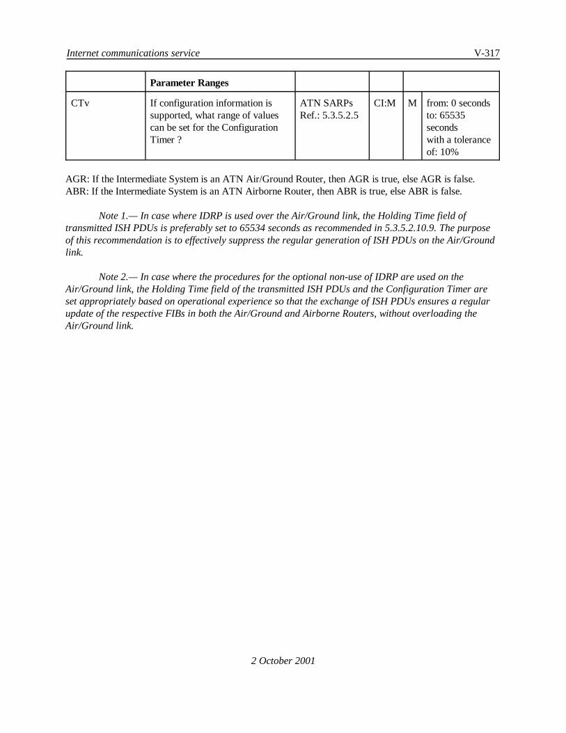
Internet communications service V-317
Parameter Ranges
2 October 2001
CTv If configuration information issupported, what range of valuescan be set for the ConfigurationTimer ?
ATN SARPsRef.: 5.3.5.2.5
CI:M M from: 0 secondsto: 65535secondswith a toleranceof: 10%
AGR: If the Intermediate System is an ATN Air/Ground Router, then AGR is true, else AGR is false.ABR: If the Intermediate System is an ATN Airborne Router, then ABR is true, else ABR is false.
Note 1.— In case where IDRP is used over the Air/Ground link, the Holding Time field oftransmitted ISH PDUs is preferably set to 65534 seconds as recommended in 5.3.5.2.10.9. The purposeof this recommendation is to effectively suppress the regular generation of ISH PDUs on the Air/Groundlink.
Note 2.— In case where the procedures for the optional non-use of IDRP are used on theAir/Ground link, the Holding Time field of the transmitted ISH PDUs and the Configuration Timer areset appropriately based on operational experience so that the exchange of ISH PDUs ensures a regularupdate of the respective FIBs in both the Air/Ground and Airborne Routers, without overloading theAir/Ground link.

V-318 Manual of Technical Provisions for the Aeronautical Telecommunication Network (ATN)
2 October 2001
5.8.3 Intermediate System to Intermediate System Inter-DomainRouting Information Exchange Protocol
5.8.3.1 General
5.8.3.1.1 With theexception of AirborneRouters that implement the procedures for theoptional non-useof IDRP, ATN Routers shall implement ISO/IEC 10747, including the ATN Specific Features specified in thissection, and the APRLs specified in 5.8.3.5.
5.8.3.2 ATN Specific Features
5.8.3.2.1 Purpose of ATN Specific Features
Note.— The ATN Specific Features specified in the following subsections support user requirementsconcerned with:
a) Ensuring that application data passed over Air/Ground data links conforms withany national and/or ITU restrictions applicable to that Air/Ground data link;
b) Ensuring that a classification scheme can be applied to routes throughout the ATNGround Environment, reflecting the expected QoS available over each such route;
c) Ensuring that information on Air/Ground subnetwork types that a route passes overis available for determining which route to choose for a given application*s data;
d) Ensuring that changes to routing information that report negative changes (e.g. adowngrading of the classification of a route) are reported in a timely manner;
e) Ensuring that routing information is received from an authentic source .
5.8.3.2.2 Use of the Security Path Attribute
5.8.3.2.2.1 ATN Routers supporting inter-domain routing shall support the IDRP Security Path Attributewith a Security Registration Identifier set to the value defined in 5.6.2.2.6 for the ATN Security RegistrationIdentifier.
5.8.3.2.2.2 The Security Information provided with a so identified IDRP Security Path Attribute shallconsist of zero one or more Security Tag Sets as defined in 5.6.2.2.6.
5.8.3.2.2.3 The following Security Tag Sets shall be supported:
a) The Air/Ground Subnetwork type, as defined in 5.8.3.2.3.2, and
b) The ATSC Class, as defined in 5.8.3.2.3.3.

Internet communications service V-319
2 October 2001
5.8.3.2.2.4 Recommendation.— When an ATN Router supports data classified according to a securitypolicy and for the purpose of implementing mandatory access controls, then the ATN Router should alsosupport the security classification Security Tag Set defined in 5.6.2.2.6.
5.8.3.2.2.5 When a route is available over more than one Air/Ground subnetwork type, then a separateSecurity Tag Set shall be encoded into this field to identify each Air/Ground subnetwork that may support theroute.
5.8.3.2.2.6 When an Air/Ground Subnetwork is restricted to carrying data of only certain traffic types,then the Security Tag Set that identifies that Air/Ground Subnetwork shall enumerate the Traffic Types thatmay pass over that subnetwork.
5.8.3.2.2.7 At most one ATSC Class Security Tag Set shall be present in a route*s Security PathAttribute.
5.8.3.2.2.8 An ATSC Class Security Tag Set shall not be present when one or more Air/GroundSubnetwork Type Security Tag Sets are also present, and when none of these Air/Ground Subnetwork TypeSecurity Tag Sets indicates support of ATN Operational Communications traffic type — Air Traffic ServiceCommunications traffic category.
5.8.3.2.3 Encoding of the Security Path Attribute Security Information Field
5.8.3.2.3.1 General
5.8.3.2.3.1.1 The Security Path Attribute Security Information Field shall comprise zero, one or moreSecurity Tag Sets as defined in 5.6.2.2.6.
Note.— The Security Tag Set format defined for use with CLNP in 5.6, has been adopted here as aconvenient method for the extensible encoding of security related information.
5.8.3.2.3.2 Encoding of the Air/Ground Subnetwork Type Security Tag Set
5.8.3.2.3.2.1 The Tag Set Name of the Air/Ground Subnetwork Type Security Tag Set shall be set to [00000101], and the Security Tag shall always be two octets in length.
5.8.3.2.3.2.2 The first (lowest numbered) octet of the Security Tag shall define the Air/Ground subnetworktype over which the route may be available according to Table 5.8-4.
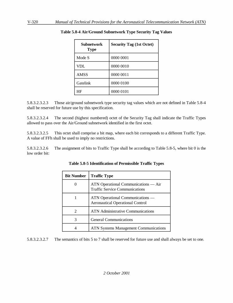
V-320 Manual of Technical Provisions for the Aeronautical Telecommunication Network (ATN)
2 October 2001
Table 5.8-4 Air/Ground Subnetwork Type Security Tag Values
SubnetworkType
Security Tag (1st Octet)
Mode S 0000 0001
VDL 0000 0010
AMSS 0000 0011
Gatelink 0000 0100
HF 0000 0101
5.8.3.2.3.2.3 Those air/ground subnetwork type security tag values which are not defined in Table 5.8-4shall be reserved for future use by this specification.
5.8.3.2.3.2.4 The second (highest numbered) octet of the Security Tag shall indicate the Traffic Typesallowed to pass over the Air/Ground subnetwork identified in the first octet.
5.8.3.2.3.2.5 This octet shall comprise a bit map, where each bit corresponds to a different Traffic Type.A value of FFh shall be used to imply no restrictions.
5.8.3.2.3.2.6 The assignment of bits to Traffic Type shall be according to Table 5.8-5, where bit 0 is thelow order bit:
Table 5.8-5 Identification of Permissible Traffic Types
Bit Number Traffic Type
0 ATN Operational Communications — AirTraffic Service Communications
1 ATN Operational Communications —Aeronautical Operational Control
2 ATN Administrative Communications
3 General Communications
4 ATN Systems Management Communications
5.8.3.2.3.2.7 The semantics of bits 5 to 7 shall be reserved for future use and shall always be set to one.
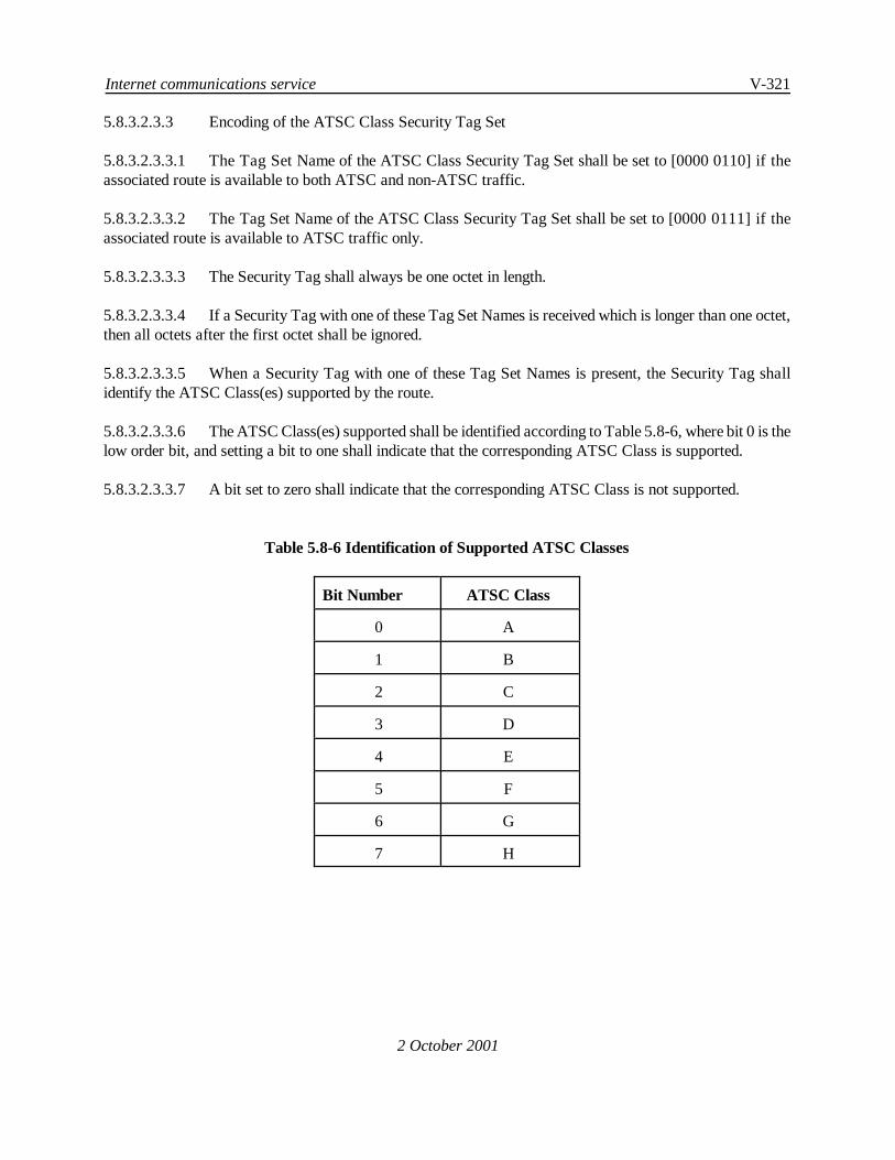
Internet communications service V-321
2 October 2001
5.8.3.2.3.3 Encoding of the ATSC Class Security Tag Set
5.8.3.2.3.3.1 The Tag Set Name of the ATSC Class Security Tag Set shall be set to [0000 0110] if theassociated route is available to both ATSC and non-ATSC traffic.
5.8.3.2.3.3.2 The Tag Set Name of the ATSC Class Security Tag Set shall be set to [00000111] if theassociated route is available to ATSC traffic only.
5.8.3.2.3.3.3 The Security Tag shall always be one octet in length.
5.8.3.2.3.3.4 If a Security Tag with one of these Tag Set Names is received which is longer than one octet,then all octets after the first octet shall be ignored.
5.8.3.2.3.3.5 When a Security Tag with one of these Tag Set Names is present, the Security Tag shallidentify the ATSC Class(es) supported by the route.
5.8.3.2.3.3.6 The ATSC Class(es) supported shall be identified according to Table 5.8-6, where bit 0 is thelow order bit, and setting a bit to one shall indicate that the corresponding ATSC Class is supported.
5.8.3.2.3.3.7 A bit set to zero shall indicate that the corresponding ATSC Class is not supported.
Table 5.8-6 Identification of Supported ATSC Classes
Bit Number ATSC Class
0 A
1 B
2 C
3 D
4 E
5 F
6 G
7 H

V-322 Manual of Technical Provisions for the Aeronautical Telecommunication Network (ATN)
2 October 2001
5.8.3.2.4 Update of Security Information
5.8.3.2.4.1 The Air/Ground Subnetwork Type
5.8.3.2.4.1.1 When a Route which contains a Security Path Attribute and has the ATN Security PolicyIdentifier as the Security Path Attribute’s Security Registration Identifier is either:
a) received by an Air/Ground Router from an Airborne Router,
or
b) advertised by an Air/Ground Router to an Airborne Router which has not signaled itscapability to receive and process UPDATE PDUs without air/ground subnetworktype security tag(s),
Note.— An ATN Airborne Router signals its capability to receive and process UPDATE PDUswithout air/ground subnetwork type security tag(s) by using the ATN Data Link Capability Parameter (see5.8.2.1.3) contained in the options part of downlinked ISH PDU(s).
then the Security Path Attribute*s Security Information shall be updated as follows:
1) unless not already contained in the Security Information, an Air/Ground SubnetworkType Security Tag shall be added for each Air/Ground Subnetwork supporting theadjacency between the Air/Ground and Airborne Router ;
2) for each Air/Ground Subnetwork Type Security Tag present in or added to the route,if ITU requirements or local policies restrict the Traffic Types that may pass overthat subnetwork then the second octet of the security tag shall be modified to set tozero the bits corresponding to each traffic type not supported by that Air/GroundSubnetwork.
Note 1.— According to the procedures specified in 5.3.5.2.12 for the optional non-use of IDRP overan air-ground data link, this update of the Security information also includes routes which have beenoriginated by an Air/Ground Router on behalf of an Airborne Router not implementing IDRP.
Note 2.— ITU or local policy restriction(s) on the traffic type(s) that may pass over the mobilesubnetwork are known to the Air/Ground Router from local configuration information.
5.8.3.2.4.1.2 When a route containing one or more Air/Ground Subnetwork Tags is advertised over anadjacency that supports only ATSC traffic, the Air/Ground Subnetwork Tags shall be updated such that thesecond octet of the security tag shall be modified to set to zero the bits corresponding to all Traffic Types otherthan ATSC.
5.8.3.2.4.1.3 Any Air/Ground Subnetwork Security Tags with a second octet that is all zeroes shall beremoved from the route.
Internet communications service V-323
2 October 2001
5.8.3.2.4.1.4 If all Air/Ground Subnetwork Security Tags present have a zero second octet then the routeshall not be advertised over this adjacency.
5.8.3.2.4.2 The ATSC Class
5.8.3.2.4.2.1 When a route is advertised to an adjacent Ground or Air/Ground BIS or to an adjacentAirborne BIS which has not signalled its capability to support UPDATE PDUs without Air/GroundSubnetwork Type Security Tag (see 5.8.2.1.3) then:
a) if the route has been originated by an Air/Ground Router according to the proceduresfor the optional non-use of IDRP (as specified in 5.3.5.2.12), and the adjacency withthe Airborne Router is over an Air/Ground Data Link approved for ATSC use, thenan ATSC Class Security Tag shall be added to the route identifying the ATSCClass(es) supported by the Adjacency with that Airborne Router;
b) if the route had been received from an Airborne Router by an Air/Ground Router,over an Air/Ground Data Link approved for ATSC use, then an ATSC Class SecurityTag shall be added, replacing any that may already be present, identifying the ATSCClass(es) supported by the adjacency with that Airborne Router;
c) if the route
1) has been originated locally (i.e. within the same Routing Domain) by aRouter other than an Airborne Router, and
2) is required by the local Security Policy to be available for ATSC traffic, and
3) is to be advertised to an adjacent BIS over an adjacency supported by one ormore subnetworks approved for ATSC traffic, then
an ATSC Class security tag shall be added to the route which identifies the ATSCClass(es) supported by the route, as defined by the local security policy, and theATSC Class(es) of the route shall be downgraded, as specified in 5.8.3.2.4.2.5, to theATSC Class(es) supported by the adjacency.
Note 1.— A route to a mobile RD’s home and a route to all AINSC and ATSC mobiles are twospecific examples of routes falling within this category. According to 5.3.7.1.2.1 e), 5.3.7.1.5.1 c), 5.3.7.3.2.1d), and 5.3.7.1.3.1 c), these routes are defined to be available for any kind of air/ground data traffic andsupporting all ATSC Classes. However, when these routes are to be advertised to an adjacent BIS, the ATSCClass security tag of these routes must be downgraded to signal the support of all ATSC classes except thosenot supported by the adjacency.
Note 2.— In the case of an Airborne Router, the ATSC Class is inserted by the Air/Ground Router(see case (b) above), and this avoids an Airborne Router having to know which Air/Ground data links areapproved for ATSC use.
d) if the route

V-324 Manual of Technical Provisions for the Aeronautical Telecommunication Network (ATN)
2 October 2001
1) has been received from another BIS, and
2) is to be advertised to an adjacent BIS over an adjacency supported by one ormore subnetworks approved for ATSC traffic, and
3) has an ATSC Class security tag that is higher than the ATSC Class that theSystem Administrator has specified as being supported by the adjacency,then
the ATSC class of the route shall be downgraded, as specified below, to the ATSCClass supported by the adjacency.
e) if the route
1) has been received from another BIS and
2) is to be advertised to an adjacent BIS over an adjacency supported bysubnetworks that are not approved for ATSC Traffic, then
the ATSC Class security tag shall be removed from the route before it is advertisedto the adjacent BIS.
f) if the route
1) has been received from an Air/Ground BIS by an Airborne BIS over anadjacency supported by oneor moresubnetworks approved for ATSC traffic,and
2) includes an ATSC Class Security Tag, then
the ATSC Class(es) of the route shall be downgraded, as specified below, to theATSC Class(es) supported by the adjacency.
Note.— The Airborne BIS knows the ATSC Class(es) supported by the adjacency from theinformation contained in the Mobile Subnetwork Capability Parameter of the ISH PDU(s) received from theadjacent Air/Ground BIS.
g) if the route
1) has been received from an Air/Ground BIS by an Airborne BIS over anadjacency supported by subnetworks that are not approved for ATSC traffic,and
2) includes an ATSC Class Security Tag, then
the ATSC Class security tag shall be removed from the route.

Internet communications service V-325
2 October 2001
5.8.3.2.4.2.2 When an ATSC Class Security tag is added to a route, then the value of the Tag Set Nameshall be set according to 5.8.3.2.3.3 and depending upon whether the adjacency has been specified to supportATSC traffic only or both ATSC and non-ATSC traffic.
5.8.3.2.4.2.3 When the ATSC Class Security Tag indicating support for both ATSC andnon-ATSC trafficis updated then the Tag Set Name shall be changed to that indicating support for ATSC only traffic if theadjacency is specified to support only ATSC traffic.
5.8.3.2.4.2.4 In all other cases, the ATSC Class Security Tag Name shall not be modified.
Note.— The Tag Set Name is set to [0000 0110] when both ATSC and non-ATSC traffic is supported,and to [0000 0111] when only ATSC traffic is supported.
5.8.3.2.4.2.5 When the ATSC Class is downgraded, the ATSC Class Security Tag Set shall be modifiedsuch that all bits indicating support for an ATSC Class higher than that supported by the local policy shall beset to zero, and the bit corresponding to the highest ATSC Class supported by local policy shall be set to one.All remaining bits shall be unaffected.
5.8.3.2.4.2.6 Paragraph has been deleted..
5.8.3.2.4.2.7 When an ATSC Class Security Tag indicating support for ATSC only is present in a route,an Air/Ground Subnetwork Security Tag when present in the same route shall not indicate support for anytraffic type other than ATSC.
5.8.3.2.4.2.8 When a route is advertised by an Air/Ground BIS to an adjacent Airborne BIS which hassignalled its capability to support UPDATE PDUs without Air/Ground Subnetwork Type Security Tag (see5.8.2.1.3), then:
a) if the route has been originated locally (i.e. within the same Routing Domain) and isrequired by the local security policy to be available for ATSC traffic, then an ATSCClass security tag shall be added to the route which identifies the ATSC class(es)supported by the route, as defined by the local security policy, without beingdowngraded to the ATSC Class(es) temporarily supported by the adjacency;
b) if the route has been received from another BIS, the ATSC Class Security Tag shallnot be modified.
5.8.3.2.4.3 The Security Classification
5.8.3.2.4.3.1 When it is required by the local Security Policy that:
a) the router supports classified data, and
b) a route is advertised to an adjacent BIS, and
c) the highest level of protection offered by the subnetworks supporting the adjacencyis lower than that reported by a Security Classification Security Tag,

V-326 Manual of Technical Provisions for the Aeronautical Telecommunication Network (ATN)
2 October 2001
then that Security Tag shall be replaced by a Security Classification Security Tag reporting the highestprotection offered by those subnetworks, as specified in the applicable security policy.
5.8.3.2.5 Route Selection
Note.— ISO/IEC 10747 clause 7.16.2 permits a Loc-RIB that is identified by a RIB_Att containingthe Security Path Attribute, to contain more than one route to the same NLRI, provided that those routesprovide the same level of protection.
5.8.3.2.5.1 When the Security Registration Identifier in the IDRP Security Path Attribute is the ATNSecurity Registration Identifier, and when no security classification is present in the route*s securityinformation, then all such routes shall be assumed to offer the same level of protection.
Note.— The purpose of this statement is to permit, within the limitations imposed by ISO/IEC 10747,the existence in the Loc-RIB of multiple routes to the same aircraft which differ in the security relatedinformation.
5.8.3.2.5.2 During the Phase 2 Routing Decision process, when:
a) two or more routes to the same or overlapping destination are found in theAdj-RIB-Ins identified by a RIB_Att that includes the Security Path Attribute, butwhich differ in the security information contained in their security path attribute, thenall such routes shall be selected and copied to the corresponding Loc-RIB.
b) two routes are found in the Adj-RIB-Ins identified by a RIB_Att that includes theSecurity Path Attribute, which differ in the security information contained in theirsecurity path attribute, and when the NLRI of the less preferable route is a propersubset of the NLRI of the more preferable route, then only the more preferable routeshall be copied to the corresponding Loc-RIB. Otherwise, both such routes shall becopied to the corresponding Loc-RIB.
5.8.3.2.6 Route Aggregation and Route Information Reduction
5.8.3.2.6.1 General
5.8.3.2.6.1.1 ATN Routers shall implement the procedures for Route Aggregation and Route InformationReduction when required to do so according to 5.8.3.2.6.2 through 5.8.3.2.6.5.
Note 1.— Route Aggregation is defined by ISO/IEC 10747 as a procedure for the merging oraggregation of two routes in order to form a single replacement route. Route Aggregation may be appliedas the result of a Routing Policy decision in order to reduce the routing information advertised to an adjacentRouter. It is also necessary to aggregate two routes in the same Loc-RIB and with identical NLRI prior tobeing advertised to an adjacent Router. This latter case of Route Aggregation is automatic, not subject toRouting Policy, and necessary for the proper dissemination of routing information.
Internet communications service V-327
2 October 2001
Note 2.— Route Information Reduction is defined by ISO/IEC 10747 as a procedure for replacingtwo or more NSAP Address Prefixes in a route*s NLRI by a single shorter NSAP Address Prefix. The decisionon when to apply Route Information Reduction is also subject to Routing Policy and is typically associatedwith the application of Route Aggregation when applied as a result of Routing Policy.
5.8.3.2.6.2 Policy Based Route Aggregation
5.8.3.2.6.2.1 Recommendation.—An Air/Ground Router should aggregate all routes to destinations inRouting Domains in its own ATN Island, other than those to destinations in its own Routing Domain.
5.8.3.2.6.2.2 Recommendation.— An Air/Ground Router should aggregate all routes to destinations inATN Islands, other than those to destinations in its own ATN Island.
5.8.3.2.6.2.3 Recommendation.—ATN Ground/Ground Routers should perform Route Aggregation andRoute Information Reduction on routes to ground destinations, in line with local policy requirements forreducing the amount of routing information distributed within the ATN Ground Environment.
Note.— The need for this will be determined according to local topology and NSAP AddressAssignment and is outside of the scope of this specification. However, this feature is a necessary conditionfor the development of a large scale and scaleable internet.
5.8.3.2.6.2.4 The selection of candidate routes for aggregation shall be performed separately for eachadjacent BIS according to a filter on each route*s destination, with a combination of inclusion and exclusionfilters.
Note.— For example, filters might be applied in order to select all routes to NSAP Address Prefixeswithin the local ATN Island, while excluding those to the local Administrative Domain.
5.8.3.2.6.3 Aggregation of Routes in the Same Loc-RIB with Identical NLRI
5.8.3.2.6.3.1 When two or more routes exist in the same Loc-RIB which have identical NLRI, then suchroutes shall be aggregated after the application of local policy rules that select routes for re-advertisement toeach adjacent BIS.
5.8.3.2.6.3.2 Such routes shall be consequently copied to the associated Adj-RIB-Out.
5.8.3.2.6.3.3 For each adjacent BIS, the resulting aggregated route shall be inserted into the associated Adj-RIB-Out.
5.8.3.2.6.3.4 In order to aggregate such routes, an ATN Router shall apply one of the following twostrategies:
a) True Route Aggregation: the routes are aggregated according to ISO/IEC 10747route aggregation procedures and the procedures for aggregation of the security pathattribute specified in 5.8.3.2.6.4 below.

V-328 Manual of Technical Provisions for the Aeronautical Telecommunication Network (ATN)
2 October 2001
b) Route Merging: the routes are merged by arbitrarily selecting one of these routes andupdating its security path attribute to the value that would have resulted had theroutes been aggregated, as above. The selected route with its updated security pathattribute is then the result of the merging procedure.
Note 1.— The former of the two strategies is preferred.
Note 2.— The second strategy has been introduced as an interim measure to simplify initialimplementations. However, this second strategy leads to a situation where routing decisions based onRD_PATH information cannot be performed, as this information is lost in the merging process. The secondstrategy may therefore be deleted in a later revision of these SARPs.
Note 3.— Whenever local policy rules that select routes for advertisement to adjacent BISs selectdifferent combinations of routes from the same Loc-RIB and with identical NLRI, for advertisement todifferent adjacent BISs, then the Route Aggregation or Merging procedure has to be carried out separatelyfor each Adj-RIB-Out. For each Adj-RIB-Out, only those routes which are eligible for advertisement to thecorresponding BIS will be input to the merging/aggregation procedure. For example, a route may not beeligible for advertisement to an adjacent BIS due to distribution restrictions or a potential route looprecognised from the RD_PATH information.
Note 4.— An aggregated route resulting from these procedures may also be aggregated with otherroutes in an Adj-RIB-Out, due to the application of local policy rules.
5.8.3.2.6.4 Aggregation of the Security Path Attribute Information Field
5.8.3.2.6.4.1 General
5.8.3.2.6.4.1.1 ATSC and non-ATSC routes with dissimilar NLRI shall not be aggregated.
Note 1.— An ATSC Route is a route containing an ATSC Class Security Tag in its Security PathAttribute. A non-ATSC Route is similarly a route that does not contain an ATSC Class Security Tag in itsSecurity Path Attribute.
Note 2.— Two possible strategies for aggregating such routes were considered. However, neithergave a satisfactory outcome. This is because the aggregated route must either be identified as an ATSCroute, or a non-ATSC route. If the aggregated route is identified as a non-ATSC route, then this would resultin ATSC routes being “hidden” when aggregated with non-ATSC routes. On the other hand, if theaggregated route is identified as an ATSC route, then this would result in a situation where an aggregatedroute that was apparently approved for ATSC Traffic, included a destination which could not be reached overa path that was approved end-to-end for ATSC Traffic. This runs the risk of creating a “black hole” forATSC Traffic.
5.8.3.2.6.4.1.2 Similarly, routes available to ATSC traffic only and routes available to both ATSC and non-ATSC traffic with dissimilar NLRI shall not be aggregated.

Internet communications service V-329
2 October 2001
5.8.3.2.6.4.1.3 Otherwise, the aggregation rules for the security information field contained in security pathattributes that include the ATN Security Registration Identifier shall be as follows.
5.8.3.2.6.4.2 Air/Ground Subnetwork Security Tag
5.8.3.2.6.4.2.1 Theaggregated security path attribute shall comprise each air/ground subnetwork security tagcontained in the security path attribute of the component routes.
5.8.3.2.6.4.2.2 When an air/ground subnetwork type security tag for the same air/ground subnetwork typeoccurs in more than one component route, then these shall be combined by a logical “OR” of the second octetof the Air/Ground Subnetwork type security tags.
5.8.3.2.6.4.2.3 Only a single air/ground subnetwork type security tag for each distinct air/ground subnetworktype shall be present in the aggregated route.
5.8.3.2.6.4.3 ATSC Class Security Tag
5.8.3.2.6.4.3.1 General
5.8.3.2.6.4.3.1.1 If an ATSC Class Security Tag is not present in any component route, then the aggregatedroute shall not contain an ATSC Class Security Tag.
5.8.3.2.6.4.3.2 Non-Identical NLRI in Component Routes
5.8.3.2.6.4.3.2.1 If the NLRI of the component routes is not identical then, when an ATSC Class security tagwith the same Tag Set Name occurs in all component routes the aggregated route shall contain an ATSC Classsecurity tag with the same Tag Set Name.
5.8.3.2.6.4.3.2.2 The ATSC Class of the aggregated route shall be the lowest ATSC Class of the aggregatedroute*s component routes, indicated by setting the value of the corresponding bit in the security tag valueto one.
5.8.3.2.6.4.3.2.3 All the other bits in this tag shall be set to zero.
5.8.3.2.6.4.3.3 Identical NLRI in Component Routes
5.8.3.2.6.4.3.3.1 If the NLRI of the component routes is identical then, when an ATSC Class security tagoccurs in one or more component routes then the aggregated route shall contain an ATSC Class security tag.
5.8.3.2.6.4.3.3.2 If an ATSC Class Tag Set occurs in all component routes and the ATSC Class Tag SetNames in all such tag sets are identical, then the Tag Set Name of the aggregated route shall be the same asin the component routes.
5.8.3.2.6.4.3.3.3 If the ATSC Class Tag Set Names in the component routes are different, or one or morecomponent routes do not include an ATSC Class Security Tag, then the ATSC Class Security Tag Set in theaggregated route shall use the Tag Set Name that indicates that the route is available for both ATSC andnon-ATSC traffic.

V-330 Manual of Technical Provisions for the Aeronautical Telecommunication Network (ATN)
2 October 2001
Note.— This Tag Set Name is defined by 5.8.3.2.3.3.1 to take the value [0000 0110].
5.8.3.2.6.4.3.3.4 The ATSC Class of the aggregated route shall be formed by a logical ‘OR* of the encodedrepresentation of the supported ATSC Class in each of the aggregated route*s component routes that containsan ATSC Class security Tag.
5.8.3.2.6.4.3.3.5 If none of the component routes contains an ATSC Class security tag, then the aggregatedroute shall not contain an ATSC Class security tag.
5.8.3.2.6.4.3.4 Security Classification Security Tag
5.8.3.2.6.4.3.4.1 When a Security Classification security tag occurs in all component routes, then theaggregated route shall contain a Security Classification security tag.
5.8.3.2.6.4.3.4.2 This tag shall be set to the lowest classification from the classifications given to theaggregated route*s component routes.
5.8.3.2.6.4.3.4.3 If a Security Classification security tag is not present in at least one component route then theaggregated route shall not contain a Security Classification security tag.
5.8.3.2.6.5 Route Information Reduction
5.8.3.2.6.5.1 Recommendation.— An Air/Ground Router should perform Route Information Reductionas permitted by the ATN Addressing Plan, before advertising aggregated routes to an Airborne Router.
Note.— It is intended that the result of Route Information Reduction is a single NSAP Address Prefixto each destination group to which aggregation is performed. However, this will only be possible if NSAPAddresses have been allocated appropriately (e.g. all systems within the same ATN Island have a singlecommon prefix for all such addresses).
5.8.3.2.6.5.2 Route Information Reduction shall be performed using local policy rules, with such routingpolicy rules required to specify when a set of NSAP Address Prefixes is replaced by a shorter NSAP AddressPrefix. Two types of rules shall be supported:
a) The explicit replacement of a set of NSAP Address Prefixes by another shorter NSAPAddress Prefix, only when all members of the set are present, or
b) The explicit replacement of a set of NSAP Address Prefixes by another shorter NSAPAddress Prefix when any members of the set are present.
5.8.3.2.7 Frequency of Route Advertisement
Note.— ISO/IEC 10747 clause 7.17.3.1 requires that the advertisement of feasible routes to somecommon set of destinations received from BISs in other Routing Domains must be separated in time by atleast minRouteAdvertisementIntervalexcept for certain identified cases. The list of exceptions to thisrequirement is extended by this specification.

Internet communications service V-331
2 October 2001
5.8.3.2.7.1 If a selected route to a given destination changes in respect of the Security Informationcontained in its Security Path Attribute, then that route shall be immediately re-advertised to all adjacent BISsto which that route had previously been advertised and not since withdrawn.
5.8.3.2.7.2 The procedure for ensuring a minimum time interval of minRouteAdvertisementIntervalbetween successive advertisements of routes to the same destination shall not apply in this case.
5.8.3.2.8 Interpretation of Route Capacity
5.8.3.2.8.1 For the ATN environment, the CAPACITY path attribute shall contain one of the values listedin Table 5.8-7, and shall be assumed to have the semantics given there:
Table 5.8-7 Interpretation of Capacity Route Metric
Value Meaning1 ... 9 Unassigned13 0 - 19.2 Kbits/sec12 19.2 - 56 Kbits/sec11 56 - 1500 Kbits/sec10 > 1500 Kbits/sec14 .. 255 Unassigned
Note.— The CAPACITY path attribute is a well known mandatory attribute that is used to denote thetraffic handling capacity of the RD_PATH listed in the same UPDATE PDU. Higher values indicate a lowertraffic handling capacity than do low values.
5.8.3.2.8.2 Those capacity route metric values which are not assigned in Table 5.8-7 shall be reserved forfuture use by this specification.
5.8.3.2.9 Network Layer Reachability Information
5.8.3.2.9.1 General
5.8.3.2.9.1.1 In support of ATN communications, ATN Routers shall encode the NLRI Addr_info field ofeach route as a list of NSAP Address Prefixes.
5.8.3.2.9.1.2 The proto_type, and proto_length fields shall be set to 1 and the Protocol field shall be set toX*81* in order to signal support of ISO/IEC 8473.
5.8.3.2.9.2 NSAP Address Prefix Alignment
5.8.3.2.9.2.1 When originating a routeor performing route information reduction, an ATN Router shall onlygenerate NSAP address prefixes that are octet-aligned.
Note 1.— For IDRP, ATN NSAP address prefixes will be eleven octets (or less).

V-332 Manual of Technical Provisions for the Aeronautical Telecommunication Network (ATN)
2 October 2001
Note 2.— 5.8.3.2.12 specifies the RIB-Atts that an ATN Router must support.
Note 3.— The above requirement does not modify the requirement in ISO/IEC 10747 to be able toaccept and correctly handle a non-octet aligned NSAP Address Prefix.
Note 4.— The above requirement simplifies prefix matching.
5.8.3.2.10 BISPDU Authentication
5.8.3.2.10.1 Authentication Type 1
Note.— Authentication type 1 is performed by an ATN Router which does not support authenticationtype 2 or if local policy permits authentication type 1 in the event that the peer router does not supportauthentication type 2.
5.8.3.2.10.1.1 ATN Routers shall support the validation of BISPDUs using Authentication Type 1.
5.8.3.2.10.1.2 When an ATN Router, which does not support ATN security services or for which local policydoes not permit authentication type 2, establishes a BIS-BIS connection, it shall set the value of theAuthentication Code in the OPEN PDU to 1, in order to indicate that the Validation field in the header of allBISPDU sent over the BIS-BIS connection will contain an unencrypted checksum.
5.8.3.2.10.1.3 When an Airborne or Air/Ground Router, which has signalled type 2 authentication during theISO/IEC 9542 ISH exchange, receives an OPEN PDU with the Authentication Code field set to 1, it shallprocess the OPEN PDU only if permitted to do so by local policy.
5.8.3.2.10.1.4 When an Airborne or Air/Ground Router, which has signalled type 2 authentication during theISO/IEC 9542 ISH exchange, receives an OPEN PDU with the Authentication Code field set to 1, and localpolicy does not permit it to process the OPEN PDU, then the OPEN PDU shall be discarded without anyfurther action.
5.8.3.2.10.1.5 When an authentication code of 1 is specified in the Authentication Code field of the OPENPDU that initiated a BIS-BIS connection, then an ATN Router shall generate a validation pattern accordingto clause 7.7.1 of ISO/IEC 10747, for each BISPDU that it sends over that connection, and similarly validatethe validation pattern of all received BISPDUs on such a connection.
5.8.3.2.10.1.6 Thetype1 authentication codeshall begenerated accordingtotheMD4 specification publishedin RFC 1320.
Note 1.— The interpretation of MD4 given in Annex B of ISO/IEC 10747 is open to ambiguousinterpretation and may lead to interoperability problems.
Note 2.— RFC 1320 supersedes RFC 1186 which was the basis for ISO/IEC 10747 Annex B.Specifications of MD4 algorithm contained in these two RFC documents are technically equivalent.
5.8.3.2.10.2 Authentication Type 2

Internet communications service V-333
2 October 2001
5.8.3.2.10.2.1 Common IDRP Connection Establishment Provisions for Authentication Type 2
Note.— The following requirements apply to the establishment of type 2 IDRP connections over bothmobile and ground subnetworks, i.e. they apply to all ATN routers supporting ATN security services.
5.8.3.2.10.2.1.1 An ATN Router which supports ATN security services shall establish a BIS-BISconnection with authentication type 2 only if type 2 authentication is permitted by local policy.
5.8.3.2.10.2.1.2 When an ATN Router establishes a BIS-BIS connection with authentication type 2,then it shall set the value of the Authentication Code to 2 in the OPEN PDU.
5.8.3.2.10.2.1.3 When an ATN Router establishes a BIS-BIS connection with authentication type 2,then it shall place a random variable (see 5.8.3.2.10.3.1.6) in the Authentication Data field of the OPEN PDU.
5.8.3.2.10.2.1.4 When an ATN Router establishes a BIS-BIS connection with authentication type 2,then it shall place a type 1 authenticator, generated according to clause 7.7.1 of ISO/IEC 10747, in theValidation Pattern field of the OPEN PDU.
Note.— Storing a type 1 authenticator in the Validation Pattern field while authentication type 2 isindicated in the Authentication Code field (only for the OPEN PDU) is an ATN specific convention in supportof type 2 authentication.
5.8.3.2.10.2.2 IDRP Connection Establishment with Authentication Type 2 over Mobile Subnetworks
5.8.3.2.10.2.2.1 An Airborne or Air/Ground Router shall establish a BIS-BIS connection withauthentication type 2 over a Mobile Subnetwork only if type 2 authentication was signalled by the peer routerin the ISO/IEC 9542 ISH PDU.
Note.— Otherwise authentication type 1 will be established if permitted as indicated in section5.8.3.2.10.1.
5.8.3.2.10.2.3 IDRP Connection Establishment with Authentication Type 2 for Air/Ground Routers
Note.— The following requirements apply to the establishment of type 2 IDRP connections byAir/Ground Routers. They are concerned with whether to perform mutual authentication (and send a publickey certificate in the Authentication Data field) or single entity authentication (and send a public key in theAuthentication Data field). In the event that the Air/Ground Router attempts to retrieve the Airborne router'scertificate subsequent to sending the ISH PDU and the certificate could not be retrieved, then the AirborneRouter will indicate public key certificate required in the OPEN PDU.
5.8.3.2.10.2.3.1 When an Air/Ground Router establishes a BIS-BIS connection with authenticationtype2 over a Mobile Subnetwork for which ‘public-key certificate required’ was signalled in the ISO/IEC 9542ISH PDU received from the Airborne Router, then it shall place its certificate path (see 5.8.3.2.10.3.1.8) in theAuthentication Data field of the OPEN PDU to be sent to the Airborne Router.

V-334 Manual of Technical Provisions for the Aeronautical Telecommunication Network (ATN)
2 October 2001
5.8.3.2.10.2.3.2 When an Air/Ground Router establishes a BIS-BIS connection with authenticationtype 2 over a Mobile Subnetwork and local policy requires mutual authentication, then it shall place itscertificate path (see 5.8.3.2.10.3.1.8) in the Authentication Data field of the OPEN PDU.
5.8.3.2.10.2.3.3 When an Air/Ground Router establishes a BIS-BIS connection with authenticationtype 2 over a Mobile Subnetwork for which ‘public-key certificate not required’ was signalled in the ISH PDUreceived from the Airborne Router and local policy does not require mutual authentication, then it shall placeits public-key information (see 5.8.3.2.10.3.1.7) in the Authentication Data field of the OPEN PDU.
5.8.3.2.10.2.3.4 When an Air/Ground Router establishes a BIS-BIS connection with authenticationtype 2 and the public key certificate of the Airborne Router could not be retrieved from a supporting certificatedelivery service, then the Air/Ground Router shall signal ‘public-key certificate required’ (see5.8.3.2.10.3.1.4)in in the Authentication Data field of the OPEN PDU.
5.8.3.2.10.2.4 IDRP Connection Establishment with Authentication Type 2 for Airborne Routers
5.8.3.2.10.2.4.1 When an Airborne Router establishes a BIS-BIS connection with authentication type2 over a Mobile Subnetwork for which ‘public-key certificate required’ was signalled in the ISO/IEC 9542 ISHPDU received from the Air/Ground Router, then it shall place its certificate path (see 5.8.3.2.10.3.1.8) in theAuthentication Data field of the OPEN PDU.
5.8.3.2.10.2.4.2 When an Airborne Router, which has sent an OPEN PDU without its public-keycertificate, receives an OPEN PDU with ‘public-key certificate required’ signalled in the Authentication Datafield, then it shall re-send its OPEN PDU with its certificate path (see 5.8.3.2.10.3.1.8) in the AuthenticationData field of the OPEN PDU.
5.8.3.2.10.2.5 IDRP Connection Establishment with Authentication Type 2 over Ground Subnetworks
5.8.3.2.10.2.5.1 When a Ground or Air/Ground Router establishes a BIS-BIS connection withauthentication type 2 over a ground subnetwork, then it shall place its certificate path (see 5.8.3.2.10.3.1.8)in the Authentication Data field of the OPEN PDU.
5.8.3.2.10.2.6 Common Type 2 IDRP Authentication Provisions
Note.— The following authentication requirements apply to all ATN routers supporting ATN securityservices.
5.8.3.2.10.2.6.1 When an ATN Router receives an OPEN PDU with the Authentication Code field setto 2, then it shall validate the Validation Pattern field according to clause 7.7.1 of ISO/IEC 10747.
5.8.3.2.10.2.6.2 When an ATN Router receives an OPEN PDU with the Authentication Code field setto 2 and the Authentication Data field contains the peer router’s public key certificate, then it shall validate thecertificate path according to the procedure specified in 8.4.5.
5.8.3.2.10.2.6.3 When an ATN Router receives an OPEN PDU with the Authentication Code field setto 2, then it shall derive a shared session key using the ATN Key Agreement Scheme as specified in 8.5.4.

Internet communications service V-335
2 October 2001
5.8.3.2.10.2.6.4 If the Public Key Certificate received from a peer ATN router fails verification or ifa valid shared session key cannot be derived, then the OPEN PDU shall be discarded without any further action.
5.8.3.2.10.2.6.5 Once an ATN Router has derived a shared session key for a BIS-BIS connection, itshall placea messageauthenticator over theBISPDU, generated using the ATN Keyed Message AuthenticationCode Generation Primitive (AMACGP) according to the procedure specified in 8.5.6.2.1, in the ValidationPattern field of all BISPDUs it sends subsequent to the OPEN PDU exchange.
5.8.3.2.10.2.6.6 When an ATN Router, which has derived a shared session key, receives a BISPDUwith a type 2 message authenticator in the Validation Pattern field, then it shall verify the authenticator usingthe ATN Keyed Message Authentication Code Verification Primitive (AMACVP) according to the procedurespecified in 8.5.6.2.2.
Note.— Clause 7.20.1 of ISO/IEC 10747 requires BISPDUs which fail verification to be discardedwithout any further action.
5.8.3.2.10.3 Format and Encoding of IDRP BISPDU Fields to Support Authentication Type 2
5.8.3.2.10.3.1 IDRP Authentication Data Field
Note.— The Authentication Data field contains two fixed form identifiers (the VersionIdentification and the Authentication Options Identification) followed by two parameters of the formtype-length-value. One type-length-value parameter is the Random Value parameter which providesprotection against replay and intercept attacks against IDRP authentication. The Random Value parameteris defined as type-length-value to facilitate use of alternative random challenges, e.g., other standardizedpseudo-random values or other time variant parameters, in future versions of IDRP security. The othertype-length-value parameter in the Authentication Data field is either the Public Key Information Parameteror the Certificate Path parameter. The former is sent by the Air/Ground Router to the Airborne Router whensingle entity authentication is provided while the latter is sent when mutual authentication is performed overthe Air/Ground subnetwork or if IDRP security is performed over ground subnetworks. These parametersare type-length-value to facilitate use of alternate algorithms and/or domain parameters in future versions.
5.8.3.2.10.3.1.1 For Authentication Type2, the IDRP Authentication Data field shall contain the itemsillustrated in Figure 5.8-3.
Version Identification Authentication Options Identification Variable Length Parameters
Octet 1 2 3 ... end
Figure 5.8-3: Format of IDRP Authentication Data Field
5.8.3.2.10.3.1.2 ATN Routers which support Authentication Type 2 shall ignore unrecognizedtype-length-value parameters.
Note.— This requirement will enable backwards compatibility of future versions of IDRPsecurity.

V-336 Manual of Technical Provisions for the Aeronautical Telecommunication Network (ATN)
2 October 2001
5.8.3.2.10.3.1.3 The Version Identification shall be encoded as binary [0000 0001] to indicate the firstversion of type 2 authentication in support of ATN security services.
5.8.3.2.10.3.1.4 The assignment of bits in and the semantic of each bit for the Authentication OptionsIdentification shall be according to Table 5.8-8, with bit 0 being the low order bit.
Table 5.8-8 Semantics and Value Assignment for Authentication Options Identification Sub-Field
Bit Position Value Semantic
0 10
Public-Key Certificate RequiredPublic-Key Certificate Not Required
1 - 7 Unassigned Reserved
5.8.3.2.10.3.1.5 Those bits which are not assigned in Table 5.8-8 shall be reserved for future use bythis specification.
5.8.3.2.10.3.1.6 Random Variable Parameter
5.8.3.2.10.3.1.6.1 The Random Variable Parameter shall consist of three fields as illustrated in Figure 5.8-4.
Random VariableParameter Code
Random VariableParameter Length
Random VariableParameter Value
Octet 1 2 and 3 4 ... end
Figure 5.8-4: Format of Random Variable Parameter
5.8.3.2.10.3.1.6.2 The Random Variable Parameter Code field shall be encoded as binary [0000 0001].
5.8.3.2.10.3.1.6.3 The Random Variable Parameter Length field shall define the length in octets of theRandom Variable Parameter Value field.
5.8.3.2.10.3.1.6.4 The Random Variable Parameter Value field shall contain a 32-bit unsigned integer valuethat is encoded most significant byte first.
5.8.3.2.10.3.1.7 Public Key Information Parameter
5.8.3.2.10.3.1.7.1 The Public Key Information Parameter shall consist of three fields as illustrated inFigure 5.8-5.
Public Key InformationParameter Code
Public Key InformationParameter Length
Public Key InformationParameter Value
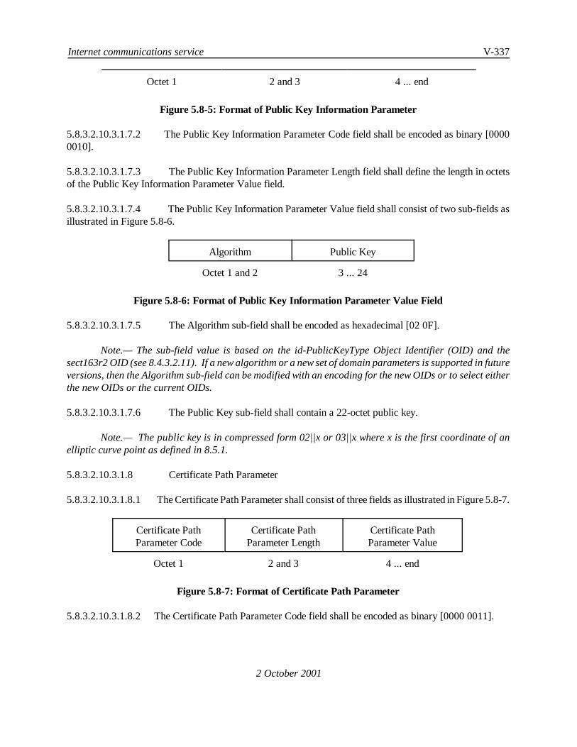
Internet communications service V-337
2 October 2001
Octet 1 2 and 3 4 ... end
Figure 5.8-5: Format of Public Key Information Parameter
5.8.3.2.10.3.1.7.2 The Public Key Information Parameter Code field shall be encoded as binary [00000010].
5.8.3.2.10.3.1.7.3 The Public Key Information Parameter Length field shall define the length in octetsof the Public Key Information Parameter Value field.
5.8.3.2.10.3.1.7.4 The Public Key Information Parameter Value field shall consist of two sub-fields asillustrated in Figure 5.8-6.
Algorithm Public Key
Octet 1 and 2 3 ... 24
Figure 5.8-6: Format of Public Key Information Parameter Value Field
5.8.3.2.10.3.1.7.5 The Algorithm sub-field shall be encoded as hexadecimal [02 0F].
Note.— The sub-field value is based on the id-PublicKeyType Object Identifier (OID) and thesect163r2 OID (see 8.4.3.2.11). If a new algorithm or a new set of domain parameters is supported in futureversions, then the Algorithm sub-field can be modified with an encoding for the new OIDs or to select eitherthe new OIDs or the current OIDs.
5.8.3.2.10.3.1.7.6 The Public Key sub-field shall contain a 22-octet public key.
Note.— The public key is in compressed form 02||x or 03||x where x is the first coordinate of anelliptic curve point as defined in 8.5.1.
5.8.3.2.10.3.1.8 Certificate Path Parameter
5.8.3.2.10.3.1.8.1 The Certificate Path Parameter shall consist of three fields as illustrated in Figure 5.8-7.
Certificate PathParameter Code
Certificate PathParameter Length
Certificate PathParameter Value
Octet 1 2 and 3 4 ... end
Figure 5.8-7: Format of Certificate Path Parameter
5.8.3.2.10.3.1.8.2 The Certificate Path Parameter Code field shall be encoded as binary [0000 0011].

V-338 Manual of Technical Provisions for the Aeronautical Telecommunication Network (ATN)
2 October 2001
5.8.3.2.10.3.1.8.3 The Certificate Path Parameter Length field shall define the length in octets of theCertificate Path Parameter Value field.
5.8.3.2.10.3.1.8.4 The Certificate Path Parameter Value field shall consist of 2 fixed and 1 repeatingsub-field as illustrated in Figure 5.8-8.
ATN RouterCertificate
Number of CACertificates
CACertificate 1
CACertificate 2
....... CACertificate n
Octet 1 ... 124 125 126 ... 244 .... end
Figure 5.8-8: Format of Certificate Path Parameter Value Field
Note.— Each CA certificate in Figure 5.8-8 above is 119 octets long.
5.8.3.2.10.3.1.8.5 The ATN Router Certificate sub-field shall contain a compressed ATN Router Certificateas defined in 8.4.3.2.
5.8.3.2.10.3.1.8.6 The Number of CA Certificates sub-field shall contain the number of CertificateAuthorities (CAs) along the path to the state CA of the peer ATN router.
5.8.3.2.10.3.1.8.7 Each CA Certificate sub-field shall contain a compressed CA Certificate as defined in8.4.3.2.
5.8.3.2.10.3.2 IDRP Validation Pattern Field
5.8.3.2.10.3.2.1 For Authentication Type 2, the low order portion of the IDRP Validation Pattern fieldshall contain the Tag resulting from application of the ATN Keyed Message Authentication Code GenerationPrimitive as specified in 8.5.6.2.1 to the entire BISPDU with all bits of the Validation Pattern field initially setto 0.
Note.— For IDRP an 80-bit Tag will be generated.
5.8.3.2.11 Restrictions on Route Advertisement
5.8.3.2.11.1 A route shall not be advertised to a BIS in another RD when:
a) The route contains the receiving RD*s RDI in its RD_PATH path attribute, or
b) The route*s RD_PATH path attribute contains the RDI of a routing domainconfederation which is being entered when the route is advertised to the other RD.
Note.— This is essential to avoid long lived black holes following the explicit withdrawal of anunfeasible route and when many alternate paths are available (e.g. within an ATN Island Backbone RDC).
5.8.3.2.12 RIB_Att Support

Internet communications service V-339
2 October 2001
Table 5.8-9 ISO/IEC 10747 Mandatory Requirements, for Which Support is Optional for ATNAirborne Routers
ISO Mandatory Requirement Notes
1. Internal Update Procedures Note 1.— There is only ever a singleBIS per routing domain on board an aircraft,and hence, internal update is not applicable.
2. Operation ofminRouteAdvertisementIntervalTimer
Note 2.— An aircraft is always an EndRouting Domain, and hence will never re-advertise routes.
3. Recognition of Next Hop Attribute Note 3.— No requirement for supportin the ATN.
4. Recognition of Residual Error, Expense,Transit Delay and PriorityDistinguishing Path Attributes
Note 4.— Never negotiated for use inthe ATN.
5. Support of RIB Refresh Note 5.— RIB Refresh is necessary forlong lived adjacencies rather than the shortlived adjacencies anticipated for ATNMobiles.
6. Support of DIST_LIST_EXCL Note 6.— There are no known userrequirements to control the distribution ofroutes to or from Mobile Systems.Implementation may also be problematic dueto changing point of attachment to the FixedATN.
7. Support of Partial Source Routing Note 7.— There are no known userrequirements for partial source routing.
8. Application of Jitter on Timers Note 8.— An aircraft is always an EndRouting Domain. Hence it will not use theminRouteAdvertisementInterval timer (see 2.above). Furthermore it is unlikely to reportchanges in locally originated routes at theMinRDOriginationInterval rate, as thisrouting information does not usually changeover the lifetime of a BIS-BIS connection.

V-340 Manual of Technical Provisions for the Aeronautical Telecommunication Network (ATN)
2 October 2001
5.8.3.2.12.1 An ATN Router incorporating IDRP shall support the following RIB_Att sets:
a) The empty RIB_Att
b) SECURITY
and shall attempt to negotiate the use of all those RIB_Atts it supports when opening a BIS-BIS connection.
5.8.3.2.12.2 The semantics of the empty RIB_Att shall be taken as implying that routes advertised underthe empty RIB_Att:
a) have a classification of “Unclassified”,
b) have not passed over any mobile subnetworks; and
c) are not available to ATSC traffic.
5.8.3.2.13 Additional Update PDU Error Handling
5.8.3.2.13.1 When an UPDATE PDU is received with a Security Path Attribute containing an ATNSecurity Registration Identifier and Security Information that contains:
a) an ATSC Class Security Tag Set, and
b) One or more Air/Ground Subnetwork type Security Tag Sets, such that none of theseSecurity Tag Sets indicates support of ATN Operational Communications — AirTraffic Service Communications, then the UPDATE PDU shall be discarded and anIDRP ERROR PDU generated with an Error_Code indicating anUPDATE_PDU_Error, and an error subcode set to 64.
5.8.3.2.14 CLNP Data PDU Parameters
5.8.3.2.14.1 The CLNP Data PDU that carries a BISPDU between two ATN Routers shall include:
a) A Security Parameter providing an ATN Security Label indicating a traffic type of“Systems Management”
b) A priority parameter indicating a PDU priority of 14.
Note.— To ensure the exchange of ISO/IEC 10747 BISPDUs over an air/ground adjacency underthe above traffic type classification, the air/ground router or airborne router respectively must be configuredin a way that includes ATN Systems Management Communications in the set of permissible traffic typesallowed to pass over the air/ground subnetwork(s) forming the air/ground adjacency. Otherwise, an IDRPconnection may not be established over the air/ground adjacency; consequently no CLNP PDUs will everflow over it and the adjacency will be unusable.
5.8.3.3 Compliance with ISO/IEC 10747
Internet communications service V-341
2 October 2001
5.8.3.3.1 General
5.8.3.3.1.1 The IDRP protocol exchange shall use the connectionless network service provided byISO/IEC 8473, as specified in ISO/IEC 10747.
5.8.3.3.2 ISO/IEC 10747 Mandatory Requirements
5.8.3.3.2.1 Airborne Router
5.8.3.3.2.1.1 An ATN AirborneRouter supporting the ISO/IEC 10747 Inter-Domain RoutingProtocol shallsupport all mandatory requirements as specified in clause 12.1 of ISO/IEC 10747 with the exception of therequirements listed in Table 5.8-9, for which support is optional.
Note.— This specification deviates from ISO/IEC 10747 for Airborne Routers, in order to simplifythe specification of operational equipment by removing all non-applicable requirements.
5.8.3.3.2.2 Ground Router
Note.— This section refers to both Air/Ground and Ground/Ground Routers generically as GroundRouters.
5.8.3.3.2.2.1 An ATN Ground Router supporting the ISO/IEC 10747 Inter-Domain Routing Protocol shallsupport all mandatory requirements as specified in clause 12.1 of ISO/IEC 10747.
5.8.3.3.2.2.2 However, over adjacencies with Airborne Routers, ATN Air/Ground Routers shall excludethe dynamic use of the following functions and features:
a) The Next Hop Path Attribute
b) The DIST_LIST_EXCL Path Attribute
c) RIB Refresh Request
d) The Residual Error Path Attribute
e) The Expense Path Attribute
f) The Priority Path Attribute
g) The Transit Delay Path Attribute
h) The Locally Defined QoS Path Attribute
i) Hierarchical Recording
j) Support of Partial Source Routing.

V-342 Manual of Technical Provisions for the Aeronautical Telecommunication Network (ATN)
2 October 2001
5.8.3.3.3 ISO/IEC 10747 Optional Requirements
5.8.3.3.3.1 An ATN Router shall support the Security Path Attribute as specified in 5.8.3.2.2 and5.8.3.2.3.
5.8.3.3.3.2 Recommendation.— An ATN Air/Ground Router should implement Route Aggregation andRoute Information Reduction Procedures.
5.8.3.3.3.3 Recommendation.—An ATN Ground/Ground Router should implement Route Aggregationand Route Information Reduction Procedures.
5.8.3.4 KeepAlive Timer
5.8.3.4.1 Recommendation.— Air/Ground Routers and Airborne Routers (i.e. Router Classes 5 and6) should utilize initial keepAlive timer values on air/ground BIS-BIS connections as follows:
Table 5.8-10 KeepAlive Timer Values on Air/Ground BIS-BIS Connections
Router Capability Nominal KeepAlive Value
AMSS and/or HFDL 180 minutes
Mode S and/or VDL only 30 minutes
Note 1.— Choice of nominal keepAlive timer value is based on the longest adjacency equipage.
Note 2.— The Leave Event is the primary means of reporting the loss of connectivity on air/groundadjacencies. A lost Leave Event in AMSS is trapped by the timer event, and routing tables are thus cleared.
5.8.3.4.2 Recommendation.— Ground/Ground Routers and Air/Ground Routers (i.e. Router Classes 4and 5) should utilize initial keepAlive timer values in the range of 5 to 60 seconds on ground/ground BIS-BISconnections.
5.8.3.4.3 Air/Ground and Airborne Router implementations (i.e. Router Classes 5 and 6) shallimplement the capability of different timer values on separate BIS-BIS connections.
Note.— ISO/IEC 10747 section 11.4 in the definition of the adjacentBISPkg-P PACKAGE requireseach BIS-BIS connection to operate a separate hold and keepAlive timer.
5.8.3.5 APRLs
5.8.3.5.1 General
5.8.3.5.1.1 An implementation of the ISO/IEC 10747 protocol shall be used in ATN Routers if and onlyif its PICS is in compliance with the APRLs specified in the following sections.

Internet communications service V-343
2 October 2001
Note.— The IDRP requirements list is a statement of which capabilities and options of the protocolat minimum are required to be implemented for the ATN environment. The requirements list may be used bythe protocol implementor as a check list to conform to this standard; by the supplier and procurer to providea detailed indication of the capabilities of an implementation; by the user to check the possibility ofinterworking between two different implementations; and by the protocol tester, as the basis for selectingappropriate tests against which to assess the claim for conformance to the protocol.
5.8.3.5.2 ATN Specific Protocol Requirements
Item Description ATNSARPs Ref
G-GRouter
A/GRouter
AirborneRouter
ATNIDRP1 Does this BIS encode and use theSecurity Path Attribute?
5.8.3.2.2,5.8.3.2.3
M M M
ATNIDRP2 Does this BIS immediately re-advertise routes if the securityinformation contained in the route’ssecurity path attribute changes?
5.8.3.2.7 M M -
ATNIDRP3 Does this BIS support ‘policy basedroute aggregation’?
5.8.3.2.6.2 O O -
ATNIDRP4 Does this BIS support ‘policy basedroute information reduction’?
5.8.3.2.6.5 O O -
ATNIDRP5 Does this BIS support aggregation ofroutes with identical NLRI using‘true route aggregation’?
5.8.3.2.6.3 O.1 O.1 -
ATNIDRP6 Does this BIS support aggregation ofroutes with identical NLRI using‘route merging’?
5.8.3.2.6.3 O.1 O.1 -
ATNIDRP7 Does this BIS support aggregation ofsecurity path attribute informationfield?
5.8.3.2.6.4 M M -

V-344 Manual of Technical Provisions for the Aeronautical Telecommunication Network (ATN)
2 October 2001
5.8.3.5.3 IDRP General
Item Description ISO/IEC10747 Ref.
ISOStatus
G-GRouter
A/GRouter
AirborneRouter
BASIC Are all basic BIS functionsimplemented?
12.1 M M M M
MGT Is this system capable of beingmanaged by the specifiedmanagement information?
11 M O O O
VER Does this BIS support VersionNegotiation?
7.8 M M M M
RTSEP Does this BIS support theROUTE_SEPARATORattribute?
7.12.1 M M M M
HOPS Does this BIS support theRD_HOP_COUNT attribute?
7.12.13 M M M M
PATH Does this BIS support theRD_PATH attribute?
7.12.3 M M M M
CAPY Does this BIS support theCapacity Attribute?
7.12.15 M M M M
FSM Does this BIS manage BIS-BISconnections according to the BISFSM description?
7.6.1 M M M M
FCTL Does this BIS provide flowcontrol?
7.7.5 M M M M
SEQNO Does this BIS provide sequencenumber support?
7.7.4 M M M M
INTG1 Does this BIS provide DataIntegrity using authenticationtype 1?
7.7.1 O.1 M M M
INTG2 Does this BIS provide DataIntegrity using authenticationtype 2?
7.7.2 O.1 O O O
INTG3 Does this BIS provide DataIntegrity using authenticationtype 3?
7.7.3 O.1 O O O

Internet communications service V-345
Item Description ISO/IEC10747 Ref.
ISOStatus
G-GRouter
A/GRouter
AirborneRouter
2 October 2001
ERROR Does this BIS handle errorhandling for IDRP?
7.20 M M M M
RIBCHK Does this BIS operate in a “fail-stop” manner with respect tocorrupted routing information?
7.10.2 M M M M
Note.— The interpretation of the Item MGT is that mandatory compliance requires that access tothe MO is provided via a Systems Management Agent. Remote Systems Management is not required for thisedition of the SARPs and hence it is not reasonable to require mandatory support for this requirement.
5.8.3.5.4 IDRP Update Send Process
Item Description ISO/IEC10747 Ref.
ISOStatus
G-GRouter
A/GRouter
AirborneRouter
INT Does the BIS provide the internalupdate procedures?
7.17.1 M M M O
RTSEL Does this BIS support theMinRouteAdvertisementIntervalTimer (except in the case specifiedin ATNIDRP2)?
7.17.3.1 M M M O
RTORG Does this BIS support theMinRDOriginationInterval Timer?
7.17.3.2 M M M M
JITTER Does this BIS provide jitter on itstimers?
7.17.3.3 M M M O
5.8.3.5.5 IDRP Update Receive Process
Item Description ISO/IEC10747 Ref.
ISOStatus
G-GRouter
A/GRouter
AirborneRouter
INPDU Does the BIS handle inboundBISPDUs correctly?
7.14 M M M M
INCONS Does this BIS detect inconsistentrouting information?
7.15.1 M M M INT:O
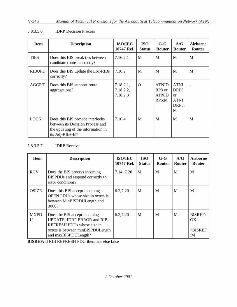
V-346 Manual of Technical Provisions for the Aeronautical Telecommunication Network (ATN)
2 October 2001
5.8.3.5.6 IDRP Decision Process
Item Description ISO/IEC10747 Ref.
ISOStatus
G-GRouter
A/GRouter
AirborneRouter
TIES Does this BIS break ties betweencandidate routes correctly?
7.16.2.1 M M M M
RIBUPD Does this BIS update the Loc-RIBscorrectly?
7.16.2 M M M M
AGGRT Does this BIS support routeaggregations?
7.18.2.1,7.18.2.2,7.18.2.3
O ATNIDRP3 orATNIDRP5:M
ATNIDRP3orATNIDRP5:M
-
LOCK Does this BIS provide interlocksbetween its Decision Process andthe updating of the information inits Adj-RIBs-In?
7.16.4 M M M M
5.8.3.5.7 IDRP Receive
Item Description ISO/IEC10747 Ref.
ISOStatus
G-GRouter
A/GRouter
AirborneRouter
RCV Does the BIS process incomingBISPDUs and respond correctly toerror conditions?
7.14, 7.20 M M M M
OSIZE Does this BIS accept incomingOPEN PDUs whose size in octets isbetween MinBISPDULength and3000?
6.2,7.20 M M M M
MXPDU
Does the BIS accept incomingUPDATE, IDRP ERROR and RIBREFRESH PDUs whose size inoctets is between minBISPDULengthand maxBISPDULength?
6.2,7.20 M M M BISREF:OX
^BISREF:M
BISREF: if RIB REFRESH PDUthen trueelsefalse

Internet communications service V-347
2 October 2001
5.8.3.5.8 Peer Entity Authentication
Item Description ISO/IEC10747 Ref.
ISOStatus
G-GRouter
A/GRouter
AirborneRouter
AUTH Does this BIS correctly authenticatethe source of a BISPDU?
7.7.2 O M M M
Note.— Only support for an Authentication Code 1 is required.
5.8.3.5.9 IDRP CLNS Forwarding
Item Description ISO/IEC10747 Ref.
ISOStatus
G-GRouter
A/GRouter
AirborneRouter
PSRCRT Does the BIS correctly handleISO/IEC 8473 NPDUs that contain apartial source route?
8 M O OX O
DATTS Does the BIS correctly extract theNPDU-derived DistinguishingAttributes from an ISO/IEC 8473NPDU?
8.2 M M M M
MATCH Does the BIS correctly match theNPDU-derived DistinguishingAttributes with the correspondingFIB-Atts?
8.3 M M M M
EXTF Does the BIS correctly forwardNPDUs with destinations outside itsown routing domain?
8.4 M M M M
INTF Does the BIS correctly forwardNPDUs with destinations inside itsown routing domain?
8.1 M M M M
5.8.3.5.10 IDRP Optional Transitive Attributes
Item Description ISO/IEC10747 Ref.
ISOStatus
G-GRouter
A/GRouter
AirborneRouter
MEXIT Does this BIS support use of theMULTI-EXIT DISC attribute?
7.12.7 O O O O
5.8.3.5.11 Generating Well-Known Discretionary Attributes

V-348 Manual of Technical Provisions for the Aeronautical Telecommunication Network (ATN)
2 October 2001
Item Description ISO/IEC10747Ref.
ISOStatus
G-GRouter
A/GRouter
AirborneRouter
EXTG Does the BIS support generation ofthe EXT_INFO attribute?
7.12.2 O O O O
NHRS Does the BIS support generation ofthe NEXT_HOP attribute in supportof route servers?
7.12.4 O O IDRPAG:OX
^IDRPAG:O
O
NHSN Does the BIS support generation ofthe NEXT_HOP attribute to advertiseSNPAs?
7.12.4 O O IDRPAG:OX
^IDRPAG:O
O
DLI Does the BIS support generation ofthe DIST_LIST_INCL attribute?
7.12.5 O O O O
DLE Does the BIS support generation ofthe DIST_LIST_EXCL attribute?
7.12.6 O O IDRPAG:OX
^IDRPAG:O
O
TDLY Does the BIS support generation ofthe TRANSIT DELAY attribute?
7.12.8 O O IDRPAG:OX
^IDRPAG:O
O
RERR Does the BIS support generation ofthe RESIDUAL ERROR attribute?
7.12.9 O O IDRPAG:OX
^IDRPAG:O
O
EXP Does the BIS support generation ofthe EXPENSE attribute?
7.12.10 O O IDRPAG:OX
^IDRPAG:O
O
LQOSG
Does the BIS support generation ofthe LOCALLY DEFINED QOSattribute?
7.12.11 O OX OX OX

Internet communications service V-349
Item Description ISO/IEC10747Ref.
ISOStatus
G-GRouter
A/GRouter
AirborneRouter
2 October 2001
HREC Does the BIS support generation ofthe HIERARCHICAL RECORDINGattribute?
7.12.12 O OX OX OX
SECG Does the BIS support generation ofthe SECURITY attribute?
7.12.14 O M M M
PRTY Does the BIS support generation ofthe PRIORITY attribute?
7.12.16 O O IDRPAG:OX
^IDRPAG:O
O
IDRPAG: if Air/Ground adjacencythen trueelsefalse
5.8.3.5.12 Propagating Well-Known Discretionary Attributes
Item Description ISO/IEC10747 Ref.
ISOStatus
G-GRouter
A/GRouter
AirborneRouter
EXTGP Does the BIS support propagationof the EXT_INFO attribute?
7.12.2 M M M -
NHRSP Does the BIS support propagationof the NEXT_HOP attribute insupport of route servers?
7.12.4 O O IDRPAG:OX
^IDRPAG:O
-
NHSNP Does the BIS support propagationof the NEXT_HOP attribute toadvertise SNPAs?
7.12.4 O O IDRPAG:OX
^IDRPAG:O
-
DLIP Does the BIS support propagationof the DIST_LIST_INCL attribute?
7.12.5 O M M -
DLEP Does the BIS support propagationof the DIST_LIST_EXCLattribute?
7.12.6 O M IDRPAG:OX
^IDRPAG:M
-

V-350 Manual of Technical Provisions for the Aeronautical Telecommunication Network (ATN)
Item Description ISO/IEC10747 Ref.
ISOStatus
G-GRouter
A/GRouter
AirborneRouter
2 October 2001
TDLYP Does the BIS support propagationof the TRANSIT DELAYattribute?
7.12.8 O O IDRPAG:OX
^IDRPAG:O
-
RERRP Does the BIS support propagationof the RESIDUAL ERRORattribute?
7.12.9 O O IDRPAG:OX
^IDRPAG:O
-
EXPP Does the BIS support propagationof the EXPENSE attribute?
7.12.10 O O IDRPAG:OX
^IDRPAG:O
-
LQOSP Does the BIS support propagationof the LOCALLY DEFINED QOSattribute?
7.12.11 O OX OX -
HRECP Does the BIS support propagationof the HIERARCHICALRECORDING attribute?
7.12.12 O OX OX -
SECP Does the BIS support propagationof the SECURITY attribute?
7.12.14 O M M -
PRTYP Does the BIS support propagationof the PRIORITY attribute?
7.12.16 O O IDRPAG:OX
^IDRPAG:O
-
5.8.3.5.13 Receiving Well-Known Discretionary Attributes
Item Description ISO/IEC10747 Ref.
ISOStatus
G-GRouter
A/GRouter
AirborneRouter
EXTR Does the BIS recognise uponreceipt the EXT_INFO attribute?
7.12.2 M M M M
NHRSR Does the BIS recognise uponreceipt the NEXT_HOP attribute ?
7.12.4 M M M O

Internet communications service V-351
Item Description ISO/IEC10747 Ref.
ISOStatus
G-GRouter
A/GRouter
AirborneRouter
2 October 2001
DLIR Does the BIS recognise uponreceipt the DIST_LIST_INCLattribute?
7.12.5 M M M M
DLER Does the BIS recognise uponreceipt the DIST_LIST_EXCLattribute?
7.12.6 M M M O
TDLYR Does the BIS recognise uponreceipt the TRANSIT DELAYattribute?
7.12.8 M M M O
RERRR Does the BIS recognise uponreceipt the RESIDUAL ERRORattribute?
7.12.9 M M M O
EXPR Does the BIS recognise uponreceipt the EXPENSE attribute?
7.12.10 M M M O
LQOSR Does the BIS recognise uponreceipt the LOCALLY DEFINEDQOS attribute?
7.12.11 M O O O
HRECR Does the BIS recognise uponreceipt the HIERARCHICALRECORDING attribute?
7.12.12 M M M O
SECR Does the BIS recognise uponreceipt the SECURITY attribute?
7.12.14 M M M M
PRTYR Does the BIS recognise uponreceipt the PRIORITY attribute?
7.12.16 M M M O
5.8.3.5.14 IDRP Timer
Item Description ISO/IEC10747 Ref.
ISOStatus
G-GRouter
A/GRouter
AirborneRouter
Ta KeepAlive timer 11.4, ATNSARPs Ref:5.8.3.4
M M M M
Tr Retransmission (tr) timer 7.6.1.2,7.6.1.3
M M M M
Tmr maxRIBIntegrityCheck timer 7.10.2 M M M M

V-352 Manual of Technical Provisions for the Aeronautical Telecommunication Network (ATN)
Item Description ISO/IEC10747 Ref.
ISOStatus
G-GRouter
A/GRouter
AirborneRouter
2 October 2001
Tma MinRouteAdvertisement timer 7.17.3.1 M M M O
Trd MinRDOriginationInterval timer 7.17.3.2 M M M M
Tcw closeWaitDelay timer 7.6.1.5 M M M M

Internet communications service V-353
2 October 2001
5.9 Systems Management Provisions
Note 1.— The ATN is dependent upon systems management procedures to monitor and maintainthe provided quality of service. For those ATN systems, which support ATN systems management, there isa minimum set of systems management requirements which applies to each type of ATN system (ES, BIS,IS, etc.).
Note 2.— ATN systems are expected to support the general systems management capabilitiesspecified in 6.3 as the minimum functionality available to a suitably authorised and authenticated localsystems manager.
Note 3.— The details of the mechanisms used to satisfy these requirements within a givenmanagement domain are a local matter.
Note 4.— The details of the mechanisms used to satisfy the requirements for the exchange ofmanagement information across management domain boundaries are specified in Section 6 of the ATNSARPs.
— END —