the audi a4 cabriolet design and operation - … over nine years of audi cabriolet production, the...
TRANSCRIPT
27
8
Service.
278
Self Study Programme 278
For internal use only
All rights reserved. Subject to technical modification.Copyright* 2002 AUDI AG, IngolstadtDepartment I/VK-35D-85045 IngolstadtFax 0841/89-36367240.2810.97.00Technical status as at 02/02Printed in Germany
The Audi A4 CabrioletDesign and operation

In over nine years of Audi Cabriolet production, the predecessor model acquired itself the status of a "modern classic". The long-awaited new generation also has all the makings of a vehicle heading for stardom:
With a length of 4,57 metres and a width of 1,77 metres, this vehicle lends new expression to the classical elegance of the Audi Cabriolet whilst at the same time emphasising the sporty character of the make.The philosophy behind the new Audi A4 Cabriolet concept is to create the ideal all-year-round vehicle.A standard feature of the new Audi A4 Cabriolet is a fully automatic electrohydraulic convertible top with a heated glass rear window.
It goes without saying that the Audi Cabriolet convertible top offers outstanding thermal insulation to provide not only perfect winter protection but also ideal sound absorption.
At the touch of a switch in the centre console, the convertible top can be completely opened or closed in only 24 seconds.It can also be operated from outside by inserting the vehicle key in the driver's door lock.
3
Contents
Page
AttentionNoteNew
The Self Study Programme contains information on design features and functions.
The Self Study Programme is not intended as a Workshop Manual.Values given are only intended to help explain the subject matter and relate to the software version applicable when the SSP was compiled.
Use should always be made of the latest technical publications when performing maintenance and repair work.
Body
Exploded view . . . . . . . . . . . . . . . . . . . . . . . . . . . . . . . . . . . . . . . . . . . . . . . . . . . . . . . 4Portal gauge . . . . . . . . . . . . . . . . . . . . . . . . . . . . . . . . . . . . . . . . . . . . . . . . . . . . . . . . . 6Vehicle safety . . . . . . . . . . . . . . . . . . . . . . . . . . . . . . . . . . . . . . . . . . . . . . . . . . . . . . . . 8Vibration damping. . . . . . . . . . . . . . . . . . . . . . . . . . . . . . . . . . . . . . . . . . . . . . . . . . . 12
Convertible top
Convertible top design . . . . . . . . . . . . . . . . . . . . . . . . . . . . . . . . . . . . . . . . . . . . . . . 14Opening convertible top. . . . . . . . . . . . . . . . . . . . . . . . . . . . . . . . . . . . . . . . . . . . . . 16Closing convertible top. . . . . . . . . . . . . . . . . . . . . . . . . . . . . . . . . . . . . . . . . . . . . . . 18Variable convertible top compartment . . . . . . . . . . . . . . . . . . . . . . . . . . . . . . . . . . 20Convenience opening and closing of automatic convertible top . . . . . . . . . . . . 21Emergency actuation . . . . . . . . . . . . . . . . . . . . . . . . . . . . . . . . . . . . . . . . . . . . . . . . 22Hydraulic system . . . . . . . . . . . . . . . . . . . . . . . . . . . . . . . . . . . . . . . . . . . . . . . . . . . . 30Hydraulic pump . . . . . . . . . . . . . . . . . . . . . . . . . . . . . . . . . . . . . . . . . . . . . . . . . . . . . 32Hydraulic cylinders . . . . . . . . . . . . . . . . . . . . . . . . . . . . . . . . . . . . . . . . . . . . . . . . . . 343/2-way solenoid valve NV 090. . . . . . . . . . . . . . . . . . . . . . . . . . . . . . . . . . . . . . . . . 35Hydraulic "opening" functions . . . . . . . . . . . . . . . . . . . . . . . . . . . . . . . . . . . . . . . . . 36Hydraulic "closing" functions. . . . . . . . . . . . . . . . . . . . . . . . . . . . . . . . . . . . . . . . . . 50Electronic components . . . . . . . . . . . . . . . . . . . . . . . . . . . . . . . . . . . . . . . . . . . . . . . 56Block diagram . . . . . . . . . . . . . . . . . . . . . . . . . . . . . . . . . . . . . . . . . . . . . . . . . . . . . . 58
Interior monitoring system
Megawave interior monitor . . . . . . . . . . . . . . . . . . . . . . . . . . . . . . . . . . . . . . . . . . . 60
Central locking system . . . . . . . . . . . . . . . . . . . . . . . . . . . . . . . 62

4
Body
Exploded view of body

5
278_001

6
Body
Portal gauge
As is the case with the A4 Saloon, use is made for the A4 Cabriolet of the alignment bracket set VAS 6042 in combination with VAS 6042/1.
278_005
In addition to the familiar portal gauge VAS 5007, the alignment bracket accessory VAS 5007/12 is also required for the A4 Cabriolet.
278_006

7
278_007
The following mounting points are set:
– Left/right convertible top latch at windscreen frame
– A-pillar– B-pillar striker plate mount– Left/right convertible top main bearing
support
Correct positioning of the mounting points on the body ensures ideal convertible top geometry.

8
Body
Vehicle safety
Head/thoraxside airbag
Full-size driver's and frontpassenger's airbag
Safety steering columnand pedal cluster
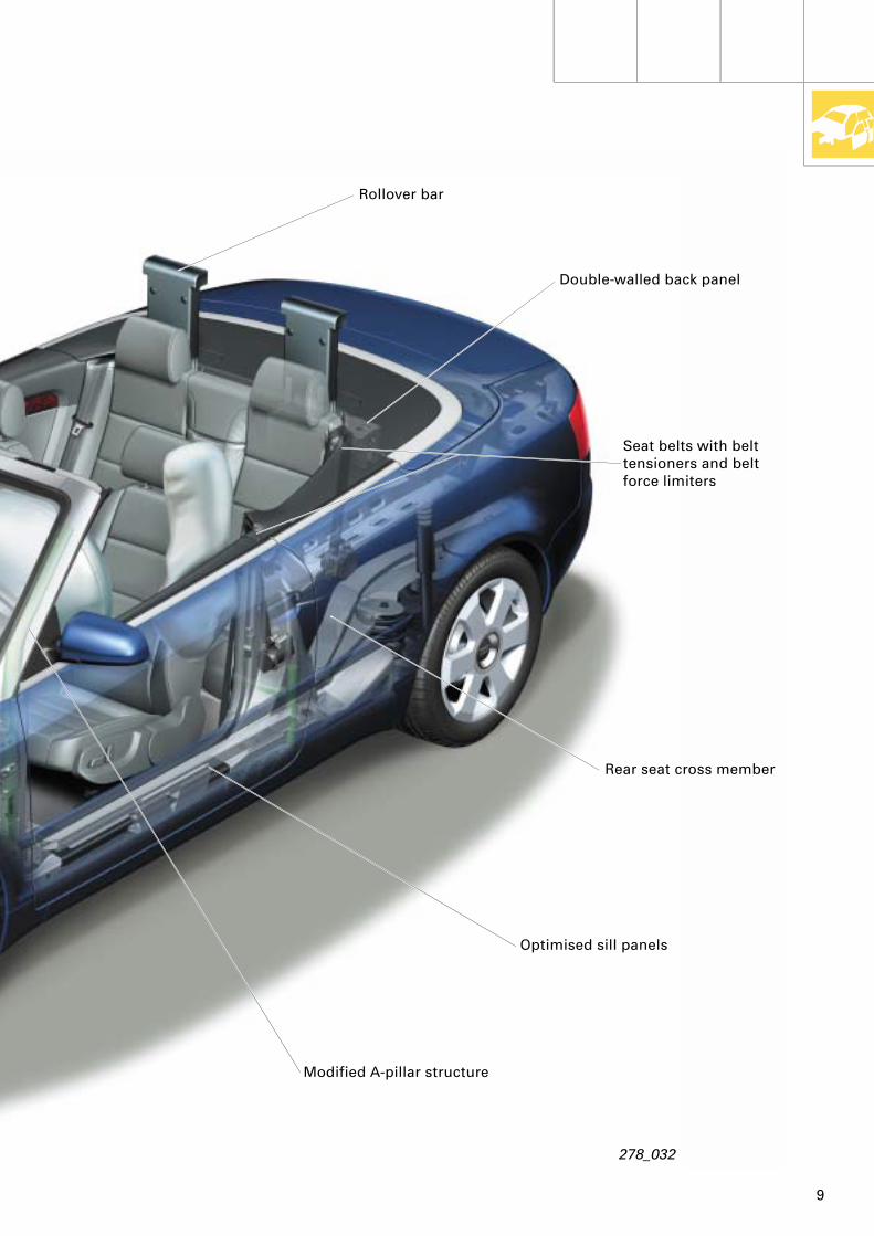
One of the main aims when developing the new A4 Cabriolet was to match the acknowledged high standards of vehicle safety already achieved by the Audi A4.This involved the incorporation of a wide range of safety features in addition to body shell modifications specific to convertible models.
9
Rollover bar
Double-walled back panel
Rear seat cross member
Optimised sill panels
Modified A-pillar structure
Seat belts with belt tensioners and belt force limiters
278_032

10
Body
The rigidity of the A-pillars is a particularly important factor with regard to occupant safety in the event of vehicle rollover. Use has therefore been made in the A4 Cabriolet of high-strength tubular bracing in addition to optimising the entire A-pillar structure.
278_033
278_036
Thanks to optimisation of their cross sections and wall thicknesses in conjunction with the use of high-strength panels, the sills play an important part in increasing body rigidity and vehicle safety.

11
The transverse rigidity of the vehicle and thus also safety in the event of side impact are enhanced by the additional high-strength tubular elements of the rear seat cross member.
278_037
Following a serious accident (rollover as well as head-on, side and rear-end impact), the two rollover bars are actuated by the control unit and moved into safety position
in a fraction of a second by releasing the pre-tensioned springs.This, together with the A-pillars, creates a safety zone for the vehicle occupants.
The back panel between rear seat and convertible top compartment is reinforced and of double-wall design. This further improves the rigidity of the body.
278_038
Pre-tensioned spring
Solenoid-operated switch
with actuationmechanism
278_039

12
Body
Vibration damping
The new A4 Cabriolet combines sporty vehicle dynamics with outstanding vibration damping characteristics.
The rigid attachment of the front subframe, diagonal bracing in the rear body structure and an extremely robust sill panel linking the front and rear ends of the vehicle all add to its overall strength.

13
278_040
All this in conjunction with the previously mentioned reinforcing measures for convertible models results in a spaceframe-type structure.The level of torsional rigidity is thus more than double that of the predecessor model.
Coordination of axle and mechanical unit vibration with the body ensures that mechanical unit and running gear mountings are ideally designed to provide vibration damping. A module cross member additionally connected to the body and precisely dimensioned steering column attachment ensure that steering wheel judder caused by the road surface is kept to a minimum.

14
Convertible top
Roof guide element 1
Convertible top design
Even at first glance it becomes apparent that the convertible top is designed to fulfill the most exacting demands of everyday driving and winter conditions.The convertible top fabric is made of particularly easy-care material and does not have to be treated with impregnating agent or the like.The structure of the convertible top takes the form of a triple layer of fabric on the outside, a 15 mm thick insulating mat and a separate inner headliner.
Convertible topfabric with
integrated rearwindow
278_010
The fabric is mechanically attached by means of fastening strips and sections to the front end of the convertible top, as well as to roof frame, bracing hoops and convertible top frame.This efficient fastening system (the convertible top is latched, clipped, riveted and bolted) guarantees ease of repair and service work.
Aluminium
Steel
By its nature, this design ensures not only simple removal and installation, but also a high level of reliability and durability.The rear window is made of mineral glass suitable for heating.

15
Front bracing hoop
Bracing hoop 1
Bracing hoop 2
Bracing hoop 4
Bracing hoop 3
Bracing hoop 5
Convertible top frame
Convertible top compartment lid latchMain support
Main guideelement
Roof guideelement 2
Convertible top compartment lid
278_009
The highest standards are also set in terms of mechanical rigidity and perfect optical integration into the appearance of the vehicle as a whole.
By combining aluminium and steel, the design of the convertible top linkage represents an ideal compromise between extreme rigidity and a minimal weight of only approx. 30 kg.The aluminium fastening sections permit straightforward removal and installation of the individual convertible top components.
The convertible top fabric is zipped directly to the intermediate layer (insulating mat) and thus indirectly to the bracing hoops.This keeps the so-called ballooning effect to a minimum.
All these items combine to ensure the harmonious integration of the roof line into the Cabriolet design throughout the entire speed range.
278_008

16
Convertible top
Opening convertible top
Prerequisites:
– Vehicle stationary / speed < 5 km/h– Ignition on– Boot lid closed– Variable convertible top compartment
lowered
Pull and hold convertible top switch in centre console.If switch is released, movement ceases instantly (freezes) and all convertible top elements remain in their current position for 10 minutes.
278_012
From this position, the convertible top can be moved again in any direction by renewed actuation of the switch.The stop mode is terminated after 10 minutes and the convertible top then folds down from its current position.The convertible top is not fully open until the warning lamp in the dash panel insert goes out and the side windows start to move.
278_011
For more information on convertible top compartment, refer to Pages 20 and 21.
Convertible top opening phases:
All the above-mentioned prerequisites must be fulfilled.Actuation of the switch locks the boot lid and at the same time activates the warning lamp in the dash panel insert. All the side windows are then lowered to a defined position.
278_013
17
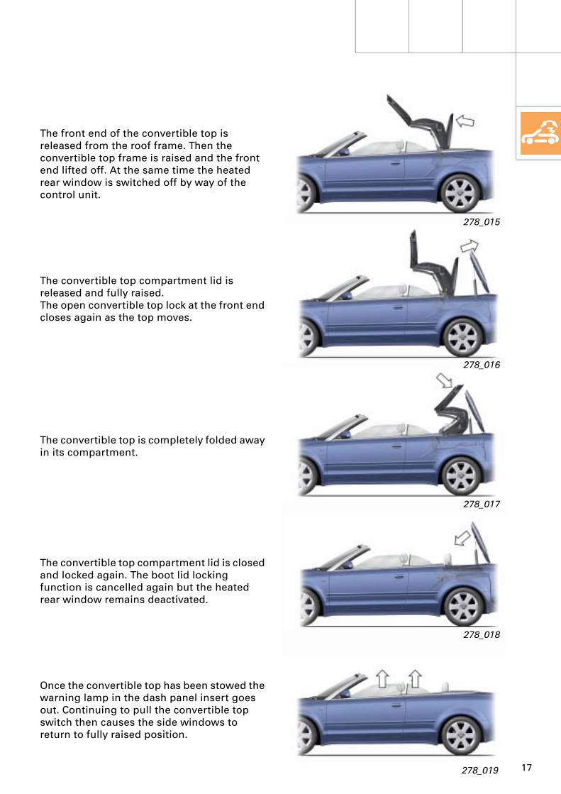
The front end of the convertible top is released from the roof frame. Then the convertible top frame is raised and the front end lifted off. At the same time the heated rear window is switched off by way of the control unit.
The convertible top compartment lid is released and fully raised.The open convertible top lock at the front end closes again as the top moves.
The convertible top is completely folded away in its compartment.
The convertible top compartment lid is closed and locked again. The boot lid locking function is cancelled again but the heated rear window remains deactivated.
Once the convertible top has been stowed the warning lamp in the dash panel insert goes out. Continuing to pull the convertible top switch then causes the side windows to return to fully raised position.
278_016
278_015
278_017
278_018
278_019

18
Convertible top
Closing convertible top
Prerequisites:
– Vehicle stationary / speed < 5 km/h– Ignition on– Boot lid closed
Press and hold down convertible top switch in centre console.If switch is released, movement ceases instantly (freezes) and all convertible top elements remain in their current position.
From this position, the convertible top can be moved again in any direction by renewed actuation of the switch.The stop mode is terminated after 10 minutes and the convertible top then folds down from its current position. The convertible top is not fully closed until the warning lamp in the dash panel insert has gone out.
278_012
278_011
Convertible top closing phases:
All the above-mentioned prerequisites must be fulfilled.Actuation of the switch locks the boot lid and at the same time activates the warning lamp in the dash panel insert.All the side windows are then lowered to a defined position. Once the windows have been lowered, the convertible top compartment lid is released and fully raised.
278_021

19
The convertible top is swivelled forwards out of its compartment and at the same time the lock at the front end of the convertible top opens.
The convertible top frame is completely raised. The compartment lid is then closed again and fully latched. The boot lid is then released.
The convertible top is swivelled towards the roof frame with the open lock facing forwards.
The convertible top frame is lowered onto the compartment lid and at the same time the front end of the convertible top comes to rest on the roof frame. Once the convertible top is in position, the lock is actuated and the front end latched again.
Once the convertible top is closed, the heated rear window is reactivated and the warning lamp in the dash panel insert goes out. Continuing to press the convertible top switch then causes the side windows to return to fully raised position.
278_023
278_022
278_024
278_025
278_026

20
Convertible top
Variable convertible top compartment
278_028
The open convertible top is completely folded away in its variable compartment.When the convertible top is closed, this compartment can be raised to increase the size of the luggage compartment.The variable compartment must have been fully lowered before the convertible top can be opened.The variable compartment cannot be raised with the convertible top open.
Variable convertible top compartment loweredOperating lever in position A
Variable convertible top compartment raisedOperating lever in position B
Lowercompart-ment tray
278_027
A message appears on the dash panel insert display if an attempt is made to open the convertible top without having lowerered the variable compartment.

21
Convenience opening and closing of automatic convertible topThe automatic convertible top can also be opened or closed by inserting the vehicle key in the driver's door lock.Opening and closing are interrupted immediately on releasing the key.
Convenience closing:
– Turn key once into closing position (1).– Within two seconds, turn key a second
time into closing position (2) and hold key in this position until convertible top is fully closed.
278_031
278_029
278_030
If vehicles are fitted with an anti-theft alarm, release button on key has to be pressed first to unlock the vehicle.
For safety reasons, actuation of the automatic convertible top by way of the key remote control function is not possible.
Convenience opening:
– Turn key once into opening position (1).– Within two seconds, turn key a second
time into opening position (2) and hold key in this position until convertible top is fully open.
22
Convertible top
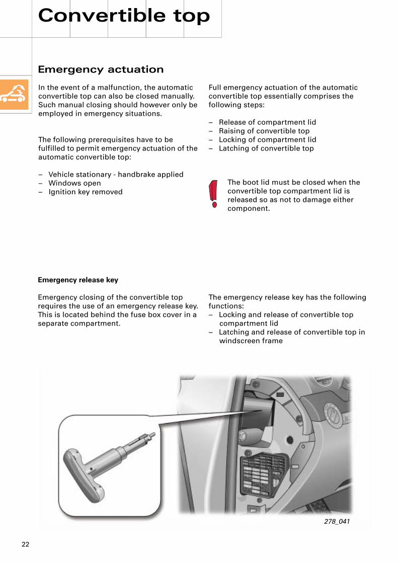
Emergency actuation
278_041
The boot lid must be closed when the convertible top compartment lid is released so as not to damage either component.
Full emergency actuation of the automatic convertible top essentially comprises the following steps:
– Release of compartment lid– Raising of convertible top– Locking of compartment lid– Latching of convertible top
In the event of a malfunction, the automatic convertible top can also be closed manually.Such manual closing should however only be employed in emergency situations.
The following prerequisites have to be fulfilled to permit emergency actuation of the automatic convertible top:
– Vehicle stationary - handbrake applied– Windows open– Ignition key removed
Emergency release key
Emergency closing of the convertible top requires the use of an emergency release key.This is located behind the fuse box cover in a separate compartment.
The emergency release key has the following functions:– Locking and release of convertible top
compartment lid– Latching and release of convertible top in
windscreen frame

23
278_051
Releasing convertible top compartment lid
The first step is to move the emergency release key into its operating position.This involves turning the red handle anti-clockwise as far as it will go.
The release system for the convertible top compartment lid is located behind the centre section of the rear seat backrest.For release purposes, this section has to be removed and the emergency release key inserted in the opening provided. The guide lugs must be felt to engage in the slots.
278_042
Then give the whole emergency release key a quarter of a clockwise turn to fix it in preliminary position.
24
Convertible top
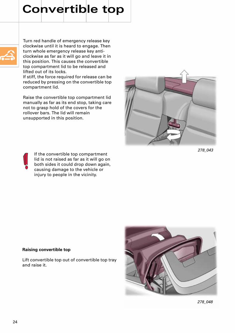
Turn red handle of emergency release key clockwise until it is heard to engage. Then turn whole emergency release key anti-clockwise as far as it will go and leave it in this position. This causes the convertible top compartment lid to be released and lifted out of its locks.If stiff, the force required for release can be reduced by pressing on the convertible top compartment lid.
Raise the convertible top compartment lid manually as far as its end stop, taking care not to grasp hold of the covers for the rollover bars. The lid will remain unsupported in this position.
278_043If the convertible top compartment lid is not raised as far as it will go on both sides it could drop down again, causing damage to the vehicle or injury to people in the vicinity.
Raising convertible top
Lift convertible top out of convertible top tray and raise it.
278_048

25
Locking convertible top compartment lid
Turn the whole emergency release key clockwise as far as it will go.This automatically lowers and locks the convertible top compartment lid.
278_044
278_049
Removing emergency release key
Turn the red handle of the emergency release key anti-clockwise as far as it will go.Then turn the whole emergency release key anti-clockwise and pull it out downwards, thus locking the convertible top compartment lid.
Closing convertible top compartment
Raise convertible top frame until it is vertical.The frame will remain unsupported in this position.Then close convertible top compartment lid again until it is resting on locks.
At this point the convertible top compartment lid cannot yet be completely closed - a gap remains between the lid and the body.

26
Convertible top
Closing and latching convertible top
Position front bracing hoop on roof frame.The emergency release key must be moved into its operating position beforehand.This involves turning the red handle anti-clockwise as far as it will go.
278_051
For latching purposes, the emergency release key is to be inserted in the opening such that the guide lugs are felt to engage in the slots provided.Then give the whole emergency release key a quarter of a clockwise turn. This fixes the emergency release key in its preliminary position and stops it dropping out of the lock system.
278_045
The opening for the roof frame release system is located in the centre of the convertible top behind a small trim cap, which has to be removed first.The vehicle key can be used for this purpose.

27
Use the emergency release key to pull the convertible top downwards and turn the key anti-clockwise as far as it will go to latch the convertible top in position.
278_047
278_052
Turn red handle of emergency release key clockwise until it is heard to engage.Turn the whole emergency release key clockwise as far as it will go.
This opens the convertible top locks and the convertible top is raised slightly.

28
Convertible top
Removing emergency release key
Turn the red handle of the emergency release key anti-clockwise as far as it will go.
278_046
It is also possible to open the convertible top using the emergency actuation function.This is to be performed in the reverse order of the procedure described above.
Then turn the whole emergency release key anti-clockwise and pull it out downwards, thus latching the convertible top.

29
Notes

30
Convertible top
Hydraulic system
Master cylinder
278_079

31
Hydraulic pump
Convertible top frame cylinder
Convertible top compartment lid cylinder
278_095

32
Convertible top
Hydraulic pump
The hydraulic pump is a rotor-type reciprocating pump which can operate in both directions depending on actuation.
Switching relay
Hydraulic pump
Electric motor
3/2-way solenoid valve
278_076

33
The rotor-type reciprocating pump draws in hydraulic fluid from the reservoir by way of the hole L.The centrifugal force of the pistons causes the cylinders to be charged. The rotor turns together with the pistons about an eccentric stator. The pistons are thus forced inwards again and the hydraulic fluid conveyed into the valve block at a pressure of max. 130 bar via the hole R.
Switching of the solenoid valves applies pressure to the hydraulic cylinders.Changing the direction of rotation of the electric motor reverses the pump process.
Restrictor
Valve housing
Pipeconnections
Shuttlevalve
Non-return valve
Pump housingPiston
Rotor
Stator
Pressure limiting valve
3/2-way solenoid valve
Hydraulic fluid reservoir
278_075
Intake shuttle valve

34
Convertible top
Hydraulic cylinders
Use is made in the Audi A4 Cabriolet of double-acting hydraulic cylinders, which can be actuated from both sides and act in two different directions to suit the situation concerned.
Hydraulic cylinder
Sealing ring
Clip
Piston crown
278_073
Hydraulic pipe connection
Piston rod
Compressionstage
Non-compression
stage

35
3/2-way solenoid valve NV 090
The flow of current through the solenoid valve coil causes the moving steel core to close the upper ball valve. At the same time, the lower ball valve is opened by way of a push rod. The hydraulic fluid can then flow via the outlet into the hydraulic cylinders.
Releasing the switch brings the movement of the convertible top to an instant halt.
The non-return valve enables the convertible top to remain in its current position (on release of convertible top switch or interruption of key-operated convenience opening/closing).
This "freezing" phase lasts for 10 minutes provided that the solenoid valve is electrically actuated.
After this period or if the ignition is switched off, depressurisation takes place and may result in uncontrolled system collapse.
With ignition off, all valves in the hydraulic control unit are opened and the convertible top can be operated manually.
Moving steel core
Coil
Inlet
Outlet
Pump
Upper ball valve
Lower ball valve
Non-return valve
278_074
Shuttle valve:

36
Convertible top
Hydraulic "opening" functions
Raising convertible top frame
Prerequisites:
– Direction of pump rotation: Clockwise– Solenoid valve F2 energised– Solenoid valve F3 energised
278_080
Co
nve
rt. t
op
co
mp
artm
. lid
cyl
.
Co
nve
rt. t
op
co
mp
artm
. lid
cyl
.
Mas
ter
cylin
der
Mas
ter
cylin
der
Co
nv.
to
p f
ram
e cy
l.
Co
nv.
to
p f
ram
e cy
l.
F1
F2
W1 S1
Clockw.Anti-clockw.
W2
Pressure limiting valve D1
Pressure limiting valve D2
Pump pressure
Return pressure
Depressurised
F3
Solenoid valve energised = ThroughflowSolenoid valve deenergised = Return open

37
Convertible top compartment lid cylinders
Pressure is applied to the non-compression stages of the convertible top compartment lid cylinders by way of the energised solenoid valve F2 and the lid remains in closed position.
Master cylinders
Solenoid valves F2 and F3 are energised.
As a result, pressure is applied to both the compression and non-compression stages of the master cylinders.
The pressure is distributed evenly over the cylinder non-compression and compression stage.As the piston surface area of the compression stage is larger than that of the non-compression stage, different forces can be generated under the same pressure conditions. The force thus acts on the compression stage, with the result that the cylinder is extended as far as its end stop and stays in this position. The convertible top remains tilted forwards.
Convertible top frame cylinders
The non-compression stages of the two frame cylinders are actuated by the switched solenoid valve F3 and raise the convertible top frame.
As it is actuated simultaneously from both sides, the shuttle valve W1 opens in the direction of the frame cylinder non-compression stages, with the connection to the cylinder compression stages being blocked by a one-direction non-return valve.
This causes the frame cylinders to be retracted and the convertible top frame to be raised.Hydraulic fluid displaced from the compression stages is routed into the reservoir.

38
Convertible top
Hydraulic "opening" functions
Opening convertible top compartment lid
Prerequisites:
– Direction of pump rotation: Clockwise– Solenoid valve F1 energised– Solenoid valve F2 energised– Solenoid valve F3 energised
278_081
F1
F2
W1 S1
Clockw.Anti-clockw.
W2
Pressure limiting valve D1
Pressure limiting valve D2
Pump pressure
Return pressure
Depressurised
F3
Co
nve
rt. t
op
co
mp
artm
. lid
cyl
.
Co
nve
rt. t
op
co
mp
artm
. lid
cyl
.
Mas
ter
cylin
der
Mas
ter
cylin
der
Co
nv.
to
p f
ram
e cy
l.
Co
nv.
to
p f
ram
e cy
l.

39
Convertible top compartment lid cylinders
Pressure is simultaneously applied from both sides by way of the energised solenoid valves F1 and F2 to the convertible top compartment lid cylinders, which are thus extended.
This is due to the larger piston surface areas in the compression stage and the consequent difference in forces arising on applying the same level of pressure.
The compartment lid is raised.
Master cylinders
Solenoid valves F2 and F3 are energised.
As a result, pressure is applied to both the compression and non-compression stages of the master cylinders.
Convertible top frame cylinders
Pressure is simultaneously applied from both sides via the energised solenoid valves F2 and F3 to the shuttle valve W1, thus causing it to open and hydraulic pressure to be routed to the non-compression stages of the convertible top frame cylinders.
As a result, the frame cylinders remain retracted and the convertible top frame is held in raised position.

40
Convertible top
Hydraulic "opening" functions
Lowering convertible top frame
Prerequisites:
– Direction of pump rotation: Anti-clockwise– Solenoid valve F1 energised– Solenoid valve F3 energised
278_082
Co
nve
rt. t
op
co
mp
artm
. lid
cyl
.
Co
nve
rt. t
op
co
mp
artm
. lid
cyl
.
Mas
ter
cylin
der
Mas
ter
cylin
der
Co
nv.
to
p f
ram
e cy
l.
Co
nv.
to
p f
ram
e cy
l.
F1
F2
W1 S1
Clockw.Anti-clockw.
W2
Pressure limiting valve D1
Pressure limiting valve D2
Pump pressure
Return pressure
Depressurised
F3
41
Convertible top compartment lid cylinders
The lid cylinders are not actuated.
Energisation of the solenoid valve F1 causes the integrated non-return valve to be operated. This prevents depressurisation of the cylinders in the compression stage and the convertible top compartment lid is closed.
Master cylinders
Hydraulic pressure is routed by way of the non-return valve S1 directly to the compression stages of the master cylinders.
These remain extended and hold the convertible top in forward position.
On account of the shuttle valve W1 and the energised solenoid valve F3, the hydraulic pressure cannot escape into the system.
Convertible top frame cylinders
Pressure is applied directly to both cylinders via the compression stage.
The cylinders are extended and the frame stowed in the convertible top compartment.
Hydraulic fluid displaced from the non-compression stage is routed into the system and fed into the reservoir via F2.

42
Convertible top
Hydraulic "opening" functions
Stowing convertible top
Prerequisites:
– Direction of pump rotation: Clockwise– Solenoid valve F1 energised– Solenoid valve F2 energised
278_083
Co
nve
rt. t
op
co
mp
artm
. lid
cyl
.
Co
nve
rt. t
op
co
mp
artm
. lid
cyl
.
Mas
ter
cylin
der
Mas
ter
cylin
der
Co
nv.
to
p f
ram
e cy
l.
Co
nv.
to
p f
ram
e cy
l.
F1
F2
W1 S1
Clockw.Anti-clockw.
W2
Pressure limiting valve D1
Pressure limiting valve D2
Pump pressure
Return pressure
Depressurised
F3

43
Convertible top compartment lid cylinders
Pressure is simultaneously applied from both sides by way of the energised solenoid valves F1 and F2 to the convertible top compartment lid cylinders.
The cylinders remain extended and the compartment lid is held in raised position.
Master cylinders
Hydraulic pressure is routed by way of the solenoid valve F2 directly to the non-compression stages of the master cylinders.
These are retracted and the convertible top is stowed in its compartment.
The hydraulic fluid displaced from the compression stage is routed via F3 into the reservoir.
Convertible top frame cylinders
Neither frame cylinder is actuated.
Both frame cylinders are partially retracted by the convertible top mechanism.

44
Convertible top
Hydraulic "opening" functions
Closing convertible top compartment lid
Prerequisites:
– Direction of pump rotation: Clockwise– Solenoid valve F2 energised
278_084
Co
nve
rt. t
op
co
mp
artm
. lid
cyl
.
Co
nve
rt. t
op
co
mp
artm
. lid
cyl
.
Mas
ter
cylin
der
Mas
ter
cylin
der
Co
nv.
to
p f
ram
e cy
l.
Co
nv.
to
p f
ram
e cy
l.
F1
F2
W1 S1
Clockw.Anti-clockw.
W2
Pressure limiting valve D1
Pressure limiting valve D2
Pump pressure
Return pressure
Depressurised
F3

45
Convertible top compartment lid cylinders
Pressure is applied by way of the energised solenoid valve F2 to the non-compression stages of the lid cylinders.
These are retracted and the compartment lid thus closed.
The hydraulic fluid draining out of the compression stage is routed via F1 into the reservoir.
Master cylinders
Hydraulic pressure is routed by way of the solenoid valve F2 directly to the non-compression stages of the master cylinders.
These thus remain retracted and the convertible top is left in its compartment.
Convertible top frame cylinders
The frame cylinders are not actuated.
They remain partially retracted.

46
Convertible top
Hydraulic "closing" functions
Raising convertible top compartment lid
Prerequisites:
– Direction of pump rotation: Clockwise– Solenoid valve F1 energised– Solenoid valve F2 energised
278_085
Co
nve
rt. t
op
co
mp
artm
. lid
cyl
.
Co
nve
rt. t
op
co
mp
artm
. lid
cyl
.
Mas
ter
cylin
der
Mas
ter
cylin
der
Co
nv.
to
p f
ram
e cy
l.
Co
nv.
to
p f
ram
e cy
l.
F1
F2
W1 S1
Clockw.Anti-clockw.
W2
Pressure limiting valve D1
Pump pressure
Return pressure
Depressurised
F3
Pressure limiting valve D2

47
Convertible top compartment lid cylinders
Pressure is simultaneously applied from both sides by way of the energised solenoid valves F1 and F2 to the convertible top compartment lid cylinders, which are thus extended.
The compartment lid is raised.
Master cylinders
Hydraulic pressure is routed by way of the solenoid valve F2 to the non-compression stages of the two master cylinders. Both master cylinders remain retracted.
Convertible top frame cylinders
The frame cylinders are not actuated.
They remain partially retracted.

48
Convertible top
Hydraulic "closing" functions
Lifting convertible top out of compartment
Prerequisites:
– Direction of pump rotation: Clockwise– Solenoid valve F1 energised– Solenoid valve F3 energised
278_086
Co
nve
rt. t
op
co
mp
artm
. lid
cyl
.
Co
nve
rt. t
op
co
mp
artm
. lid
cyl
.
Mas
ter
cylin
der
Mas
ter
cylin
der
Co
nv.
to
p f
ram
e cy
l.
Co
nv.
to
p f
ram
e cy
l.
F1
F2
W1 S1
Clockw.Anti-clockw.
W2
Pressure limiting valve D1
Pressure limiting valve D2
Pump pressure
Return pressure
Depressurised
F3

49
Convertible top compartment lid cylinders
The lid cylinders are not actuated.
Energisation of the solenoid valve F1 causes the integrated non-return valve to be operated. This prevents discharge of the cylinders in the compression stage and the convertible top compartment lid is thus closed.
Master cylinders
Hydraulic pressure is applied directly by way of the energised solenoid valve F3 to the compression stages of the two master cylinders.
The cylinders are extended and the convertible top is raised.
Convertible top frame cylinders
The frame cylinders are not actuated.
Both frame cylinders are partially extended by the convertible top mechanism.
50
Convertible top
Hydraulic "closing" functions
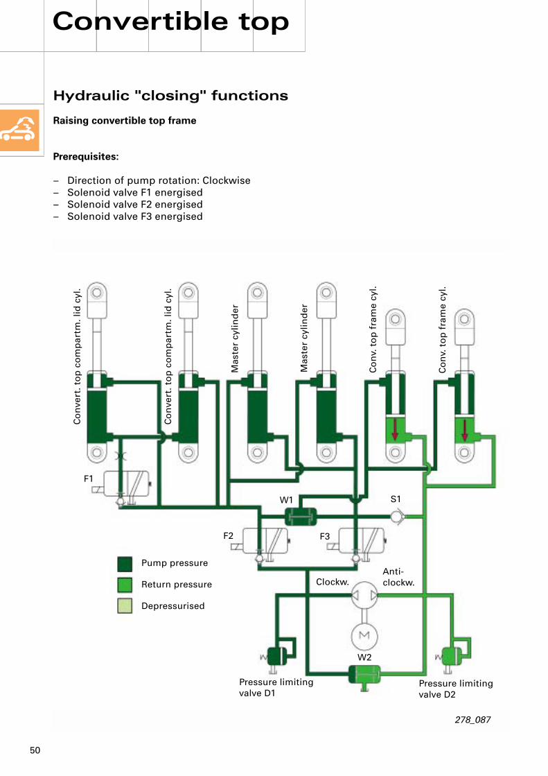
Raising convertible top frame
Prerequisites:
– Direction of pump rotation: Clockwise– Solenoid valve F1 energised– Solenoid valve F2 energised– Solenoid valve F3 energised
278_087
Co
nve
rt. t
op
co
mp
artm
. lid
cyl
.
Co
nve
rt. t
op
co
mp
artm
. lid
cyl
.
Mas
ter
cylin
der
Mas
ter
cylin
der
Co
nv.
to
p f
ram
e cy
l.
Co
nv.
to
p f
ram
e cy
l.
F1
F2
W1 S1
Clockw.Anti-clockw.
W2
Pressure limiting valve D1
Pressure limiting valve D2
Pump pressure
Return pressure
Depressurised
F3
51
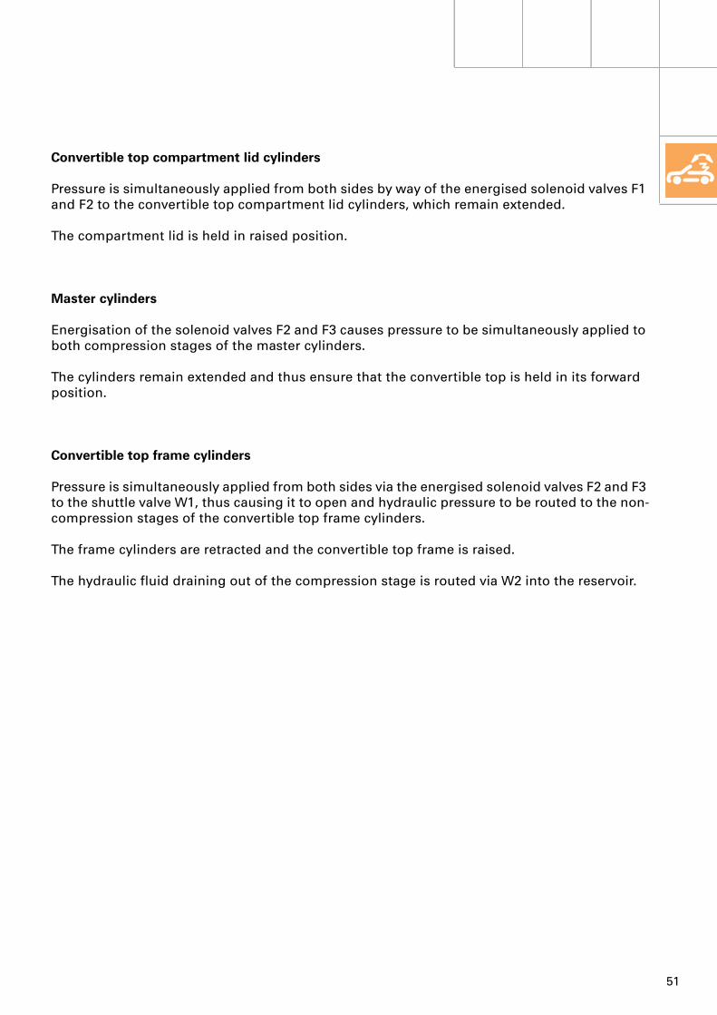
Convertible top compartment lid cylinders
Pressure is simultaneously applied from both sides by way of the energised solenoid valves F1 and F2 to the convertible top compartment lid cylinders, which remain extended.
The compartment lid is held in raised position.
Master cylinders
Energisation of the solenoid valves F2 and F3 causes pressure to be simultaneously applied to both compression stages of the master cylinders.
The cylinders remain extended and thus ensure that the convertible top is held in its forward position.
Convertible top frame cylinders
Pressure is simultaneously applied from both sides via the energised solenoid valves F2 and F3 to the shuttle valve W1, thus causing it to open and hydraulic pressure to be routed to the non-compression stages of the convertible top frame cylinders.
The frame cylinders are retracted and the convertible top frame is raised.
The hydraulic fluid draining out of the compression stage is routed via W2 into the reservoir.
52
Convertible top
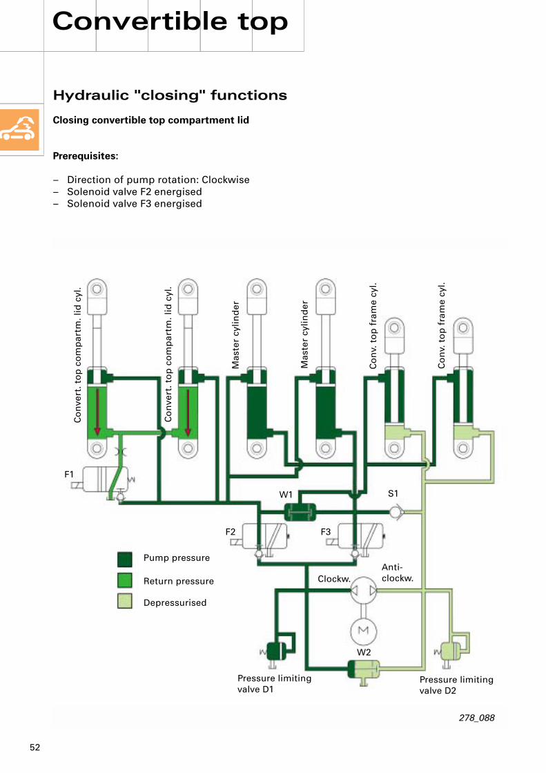
Hydraulic "closing" functions
Closing convertible top compartment lid
Prerequisites:
– Direction of pump rotation: Clockwise– Solenoid valve F2 energised– Solenoid valve F3 energised
278_088
Co
nve
rt. t
op
co
mp
artm
. lid
cyl
.
Co
nve
rt. t
op
co
mp
artm
. lid
cyl
.
Mas
ter
cylin
der
Mas
ter
cylin
der
Co
nv.
to
p f
ram
e cy
l.
Co
nv.
to
p f
ram
e cy
l.
F1
F2
W1 S1
Clockw.Anti-clockw.
W2
Pressure limiting valve D1
Pressure limiting valve D2
Pump pressure
Return pressure
Depressurised
F3

53
Convertible top compartment lid cylinders
Pressure is applied by way of the energised solenoid valve F2 to the non-compression stages of the lid cylinders.
These are retracted and the compartment lid thus closed.
The hydraulic fluid displaced in the compression stage is routed via F1 into the reservoir.
Master cylinders
Solenoid valves F2 and F3 are energised.
As a result, pressure is applied to both the compression and non-compression stages of the master cylinders.
The cylinders remain extended and ensure that the convertible top is held in its forward position.
Convertible top frame cylinders
Pressure is simultaneously applied from both sides to the shuttle valve W1.
This causes the valve to open and hydraulic pressure to be routed to the non-compression stages of the frame cylinders.
The connection to the cylinder compression stages is blocked by the one-direction non-return valve S1.
As a result, the frame cylinders remain retracted and the convertible top frame is held in raised position.

54
Convertible top
Hydraulic "closing" functions
Lowering convertible top frame
Prerequisites:
– Direction of pump rotation: Anti-clockwise– Solenoid valve F3 energised
278_089
Co
nve
rt. t
op
co
mp
artm
. lid
cyl
.
Co
nve
rt. t
op
co
mp
artm
. lid
cyl
.
Mas
ter
cylin
der
Mas
ter
cylin
der
Co
nv.
to
p f
ram
e cy
l.
Co
nv.
to
p f
ram
e cy
l.
F1
F2
W1 S1
Clockw.Anti-clockw.
W2
Pressure limiting valve D1
Pressure limiting valve D2
Pump pressure
Return pressure
Depressurised
F3
55
Convertible top compartment lid cylinders
The lid cylinders are not actuated as solenoid valve F2 is not energised.
The cylinders thus remain retracted and the convertible top compartment lid closed.
Master cylinders
Hydraulic pressure is routed by way of the non-return valve S1 directly to the compression stages of the master cylinders.
These remain extended and hold the convertible top in forward position.
On account of the shuttle valve W1 and the energised solenoid valve F3, the hydraulic pressure cannot escape into the system.
Convertible top frame cylinders
Pressure is applied to the compression stages of both frame cylinders.
The cylinders are extended and the frame lowered onto the convertible top compartment lid. The hydraulic fluid displaced from the non-compression stages is routed into the system and fed into the reservoir via F2.

56
Convertible top
Electronic components
E87 Operating and display unit for air conditioner/Climatronic
E137 Convertible top switchF169 Convertible top left latch switchF171 Convertible top stowed switchF199 Convertible top box lid latched switch 1,
leftF200 Convertible top box lid latched switch 1,
rightF201 Convertible top box lid, top switchF202 Convertible top front switchF255 Hardtop detector switchF292 Convertible top compartment tray
position switchF293 Convertible top compartment lid lock
switch, unlockedF294 Convertible top latch switch, openF295 Convertible top latch switch, closedG356 Convertible top frame position senderJ256 Convertible top operation control unitJ321 Hydraulic pump relay, convertible top
operationJ393 Convenience system central control
unitJ588 Hydraulic pump relay 2, convertible top
operationL72 Convertible top operating switch
illuminationN272 Power-operated convertible top valve 1N341 Power-operated convertible top valve 2N342 Power-operated convertible top valve 3S FuseV118 Convertible top operation hydraulic
pumpV222 Convertible top compartment lid lock
motorV223 Convertible top latch motorZ1 Heated rear window
The convertible top control system features diagnosis capability.
Adaption must be performed following replacement of the convertible top control unit or convertible top frame potentiometer.Opening and closing of the convertible top will be slowed down if adaption is not performed.
The convertible top cannot be moved if the basic position of the rear window lifters has not been learned and stored and the rear windows are fully open.

57
278_090
E87
E137 / L72
J393
F169
G356
F199
V222
F293
V118
F292
N272 / N341 / N342F200
J256F171
F202
F295
F294
V223
S
Z1
F201

Colour code
= Input signal
= Output signal
= Positive supply
= Earth
= CAN bus
= Bidirectional
Additional signals
1 2 3
M M M
30
X X
30
58 s
S S
J393
E137 L72
E87
F225 G356 J321 V118 J588N272 N341 N342
F295 F294 V223 F171 F202 F169 F293 V222 F199 F200 F292 F201 Z1
31 31
278_078
Convertible top
58
Block diagram
Convertible top control
E87 Operating and display unit for air conditioner/Climatronic
E137 Convertible top switchF169 Convertible top left latch switchF171 Convertible top stowed switchF199 Convertible top box lid latched switch 1,
leftF200 Convertible top box lid latched switch 1,
rightF201 Convertible top box lid, top switchF202 Convertible top front switchF255 Hardtop detector switchF292 Convertible top compartment tray
position switchF293 Convertible top compartment lid lock
switch, unlockedF294 Convertible top latch switch, openF295 Convertible top latch switch, closedG356 Convertible top frame position senderJ256 Convertible top operation control unitJ321 Hydraulic pump relay, convertible top
operationJ393 Convenience system central control
unitJ588 Hydraulic pump relay 2, convertible top
operationL72 Convertible top operating switch
illuminationN272 Power-operated convertible top valve 1N341 Power-operated convertible top valve 2N342 Power-operated convertible top valve 3S FuseV118 Convertible top operation hydraulic
pumpV222 Convertible top compartment lid lock
motorV223 Convertible top latch motorZ1 Heated rear window
1
2
3
K-diagnosis connection(to control unit with display in dash panel insert J285)Convenience CAN bus, high connection(to control unit with display in dash panel insert J285)Convenience CAN bus, low connection(to control unit with display in dash panel insert J285)

59
Notes
60
Interior monitoring system
Megawave interior monitor
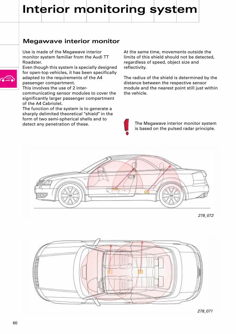
Use is made of the Megawave interior monitor system familiar from the Audi TT Roadster.Even though this system is specially designed for open-top vehicles, it has been specifically adapted to the requirements of the A4 passenger compartment.This involves the use of 2 inter-communicating sensor modules to cover the significantly larger passenger compartment of the A4 Cabriolet.The function of the system is to generate a sharply delimited theoretical "shield" in the form of two semi-spherical shells and to detect any penetration of these.
At the same time, movements outside the limits of this shield should not be detected, regardless of speed, object size and reflectivity.
The radius of the shield is determined by the distance between the respective sensor module and the nearest point still just within the vehicle.
The Megawave interior monitor system is based on the pulsed radar principle.
278_071
278_072

61
When the system is active, the module cyclically emits extremely weak radar pulses.These pulses are partially reflected by the passenger compartment and stored as an image of the monitored area.
An object penetrating this monitored area produces a change in the reflected pulses andcauses the system to trigger an alarm.
278_093
278_092

62
Interior monitoring system
Central locking system
The mode of operation of the central locking system corresponds to that of the A4 Saloon.
278_070
The interior monitor can be deactivated for locking purposes by means of the button in the driver's door storage compartment.
The interior monitor can only be deactivated with the driver's door open and deactivation is indicated by lighting of the LED in the button.
A note to all users:
This Self Study Programme is intended to familiarise readers with the Audi A4 Cabriolet.
Your opinion matters to us.
That is why we would like you to give us your thoughts on and any suggestions for future Self Study Programmes.
Please make use of fax number 0049/841 89 36 36 7 for your response.
Thank you for your assistance.
Your Service Training Team

27
8
Service.
278
Self Study Programme 278
For internal use only
All rights reserved. Subject to technical modification.Copyright* 2002 AUDI AG, IngolstadtDepartment I/VK-35D-85045 IngolstadtFax 0841/89-36367240.2810.97.00Technical status as at 02/02Printed in Germany
The Audi A4 CabrioletDesign and operation