the aurora switch installation guide. - netbergtw.com · installation using the ... installing...
TRANSCRIPT

The Aurora switch installation guide.

The Aurora switch installation guide.

iii
Table of Contents1. Introduction ........................................................................................................................ 12. Hardware Installation .......................................................................................................... 2
2.1. Installation Guidelines .............................................................................................. 32.2. Installation using the Rubber Feet ............................................................................ 42.3. Installation into a Rack ............................................................................................ 5
2.3.1. Using the rackmount kit ................................................................................ 52.4. Installing Transceivers and cables into the Switch Ports ............................................ 7
2.4.1. SFP+/SFP28 Port Connection (LC Type Connector) ....................................... 72.4.2. QSFP+/QSFP28 Port Connection .................................................................. 7
2.5. Power supply .......................................................................................................... 92.6. Connect the Power Cable ...................................................................................... 102.7. Rack-mount Safety Precautions ............................................................................. 112.8. Console port ......................................................................................................... 12
3. Netberg Aurora 720 switch ............................................................................................... 133.1. Specification .......................................................................................................... 153.2. Port groups ........................................................................................................... 173.3. Supported Cables and Transceivers ....................................................................... 18
4. Netberg Aurora 630 switch ............................................................................................... 194.1. Specification .......................................................................................................... 224.2. Port groups ........................................................................................................... 244.3. Supported Cables and Transceivers ....................................................................... 25
5. Netberg Aurora 620 switch ............................................................................................... 265.1. Specification .......................................................................................................... 295.2. Port groups ........................................................................................................... 315.3. Supported Cables and Transceivers ....................................................................... 32
6. Netberg Aurora 420 switch ............................................................................................... 336.1. Specification .......................................................................................................... 366.2. Supported Cables and Transceivers ....................................................................... 38
7. Netberg Aurora 220 switch ............................................................................................... 397.1. Specification .......................................................................................................... 417.2. Supported Cables and Transceivers ....................................................................... 42
8. ICOS quick start guide ..................................................................................................... 438.1. ICOS boot ............................................................................................................. 448.2. Linux booting up process ....................................................................................... 458.3. Access Linux ......................................................................................................... 468.4. Running ICOS via icos-console .............................................................................. 478.5. Running ICOS via icos-cli ...................................................................................... 488.6. How to login ICOS via Linux SSH .......................................................................... 498.7. How to reload ICOS .............................................................................................. 518.8. How to reload OS ................................................................................................. 52

iv
List of Figures2.1. Rubber standoffs placement ............................................................................................ 42.2. Front brackets installation ................................................................................................ 52.3. Front brackets installation ................................................................................................ 52.4. Rackmount kit installation ................................................................................................ 62.5. Transceivers and cables .................................................................................................. 72.6. Power supply .................................................................................................................. 93.1. Aurora 720 front view .................................................................................................... 133.2. Aurora 720 rear view ..................................................................................................... 134.1. Aurora 630 front view .................................................................................................... 194.2. Aurora 630 rear view ..................................................................................................... 195.1. Aurora 620 front view .................................................................................................... 265.2. Aurora 620 rear view ..................................................................................................... 266.1. Aurora 420 front view .................................................................................................... 336.2. Aurora 420 rear view ..................................................................................................... 337.1. Aurora 220 front view .................................................................................................... 397.2. Aurora 220 rear view ..................................................................................................... 39
v
List of Tables2.1. Console cable pin definition ........................................................................................... 123.1. Front panel features ...................................................................................................... 133.2. Rear panel features ....................................................................................................... 143.3. LED function description ................................................................................................ 143.4. Port groups ................................................................................................................... 174.1. Front panel features ...................................................................................................... 194.2. Rear panel features ....................................................................................................... 204.3. LED function description ................................................................................................ 204.4. Port groups ................................................................................................................... 245.1. Front panel features ...................................................................................................... 265.2. Rear panel features ....................................................................................................... 275.3. LED function description ................................................................................................ 275.4. Port groups ................................................................................................................... 316.1. Front panel features ...................................................................................................... 336.2. Rear panel features ....................................................................................................... 346.3. LED function description ................................................................................................ 347.1. Front panel features ...................................................................................................... 397.2. Rear panel features ....................................................................................................... 407.3. LED function description ................................................................................................ 40
1
Chapter 1. IntroductionThis guide is to assist the reader with the most basic form of installation and cable connection toour switches. As there is more than one switch in the Aurora series, the actual port placementmight slightly differ, however, the installation and connection logic are the same for all Netbergswitches.
Package Contents:
• One Netberg Aurora Switch
• Two AC power cords.
• One RS-232-to-RJ45 console cable.
• One pair of frontal rack-mount brackets.
• Four rubber feet with adhesive patches.
• Eight Phillips-head frontal rack-mount bracket screws.
If any of the above mention items was not found inside the package contents of thisswitch or are damaged in any way, contact your reseller immediately.

2
Chapter 2. Hardware Installation

Hardware Installation
3
2.1. Installation GuidelinesThis section will discuss the hardware installation guidelines that administrators must follow in or-der to properly and safely install this switch into the appropriate environment.
Hardware Installation
4
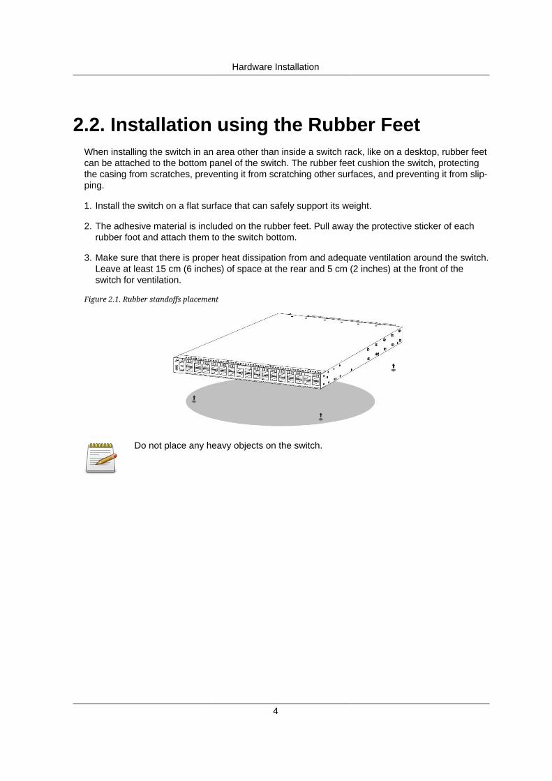
2.2. Installation using the Rubber FeetWhen installing the switch in an area other than inside a switch rack, like on a desktop, rubber feetcan be attached to the bottom panel of the switch. The rubber feet cushion the switch, protectingthe casing from scratches, preventing it from scratching other surfaces, and preventing it from slip-ping.
1. Install the switch on a flat surface that can safely support its weight.
2. The adhesive material is included on the rubber feet. Pull away the protective sticker of eachrubber foot and attach them to the switch bottom.
3. Make sure that there is proper heat dissipation from and adequate ventilation around the switch.Leave at least 15 cm (6 inches) of space at the rear and 5 cm (2 inches) at the front of theswitch for ventilation.
Figure 2.1. Rubber standoffs placement
Do not place any heavy objects on the switch.

Hardware Installation
5
2.3. Installation into a RackThe switch can be mounted in a standard 19"(1U) rack using the provided mounting brackets.The following section will explain how to install the rack-mount brackets onto the switch and thenmount the switch into a standard 1U rack-mount unit.
1. Use the supplied screws to attach a mounting bracket to each side of the Switch.
2. Align the holes in the mounting bracket with the holes in the rack.
3. Insert and tighten screws through each of the mounting brackets.
Figure 2.2. Front brackets installation
The switch can be installed directly on the rack without the use of the rail.
1. Align the built-in mounting ear to the rack holes.
2. Tighten the screws to secure the switch.
Figure 2.3. Front brackets installation
4847
4645
4443
4241
4039
3837
3635
3433
3231
3029
2827
2625
2423
2221
2019
1817
1615
1413
1211
109
81
23
45
67
RESET
PSU1
PSU2
FAN
STAT
5049
5251
5453
5655
10U10U
2.3.1. Using the rackmount kitAn optional rackmount kit is recommended when the switch is installed without a shelf.
The rackmount kit support 600~900mm cabinet.
1. Use the supplied screws to attach a rear mounting bracket to each side of the Switch.
2. Align the mounting bracket with the rear posts in the rack.
3. Insert and tighten screws through each of the mounting brackets.
4. Tighten screws on each mounting bracket.

Hardware Installation
6
Figure 2.4. Rackmount kit installation

Hardware Installation
7
2.4. Installing Transceivers and cables intothe Switch Ports
Figure 2.5. Transceivers and cables
2.4.1. SFP+/SFP28 Port Connection (LC Type Connec-tor)
The Small Form-Factor Pluggable Plus (SFP+) port is the second generation of the SFP intercon-nect system designed for 10Gb/s data rate. The SFP+ ports support 10-gigabit IEEE 802.3ae Eth-ernet for fiber mediums.
The Small Form-Factor Pluggable 28 (SFP28) port is the next generation of the SFP interconnectsystem designed for 25Gb/s data rate. The SFP28 ports enables error-free transmission of 25 Gb/s over 100 meters of OM4 multimode fiber.
The SFP+/SFP28 ports are numbered and have corresponding SFP port LEDs.
To install an SFP module, do the following:
1. Slide the SFP module into an SFP port.
Ensure the SFP module is positioned correctly before installing it into the port.
2. Push completely until the module locks into place.
3. Repeat the above procedures to install additional SFP+ modules.
The SFP port LED lights green when the network link is established.
2.4.2. QSFP+/QSFP28 Port ConnectionQSFP+ (Quad SFP) ports which support 40G/per port or fan out to 4x10G by using the fan outDAC cable.
Hardware Installation
8
QSFP28 (Quad SFP) ports which support 100G/per port or fan out to 4x25G by using the fan outDAC cable.
1. Slide the QSFP module into a QSFP port.
Ensure the QSFP module is positioned correctly before installing it into the port.
2. Push completely until the module locks into place.
3. Repeat the above procedures to install additional QSFP modules.
The QSFP port LED lights green when the network link is established.

Hardware Installation
9
2.5. Power supplyEquipped with two supply modules, the switch can operate with either one or two power supplymodules. If the switch uses two power supply modules, you can hot-swap one of the PSU duringthe operations.
One PSU is enough for a fully loaded chassis.
Figure 2.6. Power supply
The AC power connector is a standard three-pronged connector. The switch automatically adjustsits power setting to any supply voltage in the range from 100-240 VAC at 50-60 Hz.

Hardware Installation
10
2.6. Connect the Power CableConnect one end of the AC power cord, included in the package, into the grounded electrical outletat the site and insert the other end of the AC power cord into the AC power receptacle of the ACpower supply module on the back panel of the switch. The switch will automatically adjust the volt-age supplied to the voltage needed as this power supply supports any voltage power supply in therange from 100VAC to 240VAC at 50Hz to 60Hz.
The LED indicators on the front panel of the switch should lights green after power-on.

Hardware Installation
11
2.7. Rack-mount Safety PrecautionsFor your protection, observe the following rack-mount safety precautions when setting up yourequipment:
• Elevated Operating Ambient - If installed in a closed or multi-unit rack assembly, the operatingambient temperature of the rack environment may be greater than room ambient. Therefore,consideration should be given to installing the equipment in an environment compatible with themaximum ambient temperature (Tma) specified by the manufacturer.
• Reduced Air Flow - Installation of the equipment in a rack should be such that the amount of airflow required for safe operation of the equipment is not compromised.
• Mechanical Loading - Mounting of the equipment in the rack should be such that a hazardouscondition is not achieved due to uneven mechanical loading.
• Circuit Overloading - Consideration should be given to the connection of the equipment to thesupply circuit and the effect that overloading of the circuits might have on overcurrent protectionand supply wiring. Appropriate consideration of equipment nameplate ratings should be usedwhen addressing this concern.
• Reliable Earthing - Reliable earthing of rack-mounted equipment should be maintained. Partic-ular attention should be given to supply connections other than direct connections to the branchcircuit (for example, use of power strips).
• For safety, equipment should always be loaded from the bottom up. That is, install the equip-ment that will be mounted in the lowest part of the rack first, then the next higher systems, etc.
• To prevent the rack from tipping during equipment installation, the anti-tilt bar on the rack mustbe deployed.
• The mounting brackets provided must be used to securely mount the device in a rack-mountunit.

Hardware Installation
12
2.8. Console portThe console port is used for setting up and managing the switch via a connection to a console ter-minal or PC using a terminal emulation program. You can connect the switch to a terminal or PCusing the supplied console cable (RJ-45 male to RS-232 female cable) for serial communication.
Below is the console cable wiring specification table:
Table 2.1. Console cable pin definition
RJ-45 Port of Switch DB9 Female Port ofPC
Abbreviation Description
3 2 RD Received Data
6 3 TD Transmit Data
1 8 CTS Clear To Send
8 7 RTS Request To Send
Using the console port, you can perform the following:
• Configure, manage and monitor the switch using the CLI commands
• Manage and monitor network activity by Simple Network Management Protocol (SNMP) man-agement
• Upgrade the firmware
To connect to the console, do the following:
1. Connect the RJ-45 connector to the console port (|o|o ) of the switch.
2. Connect the RS-232 end to a terminal or PC.
3. Manage the switch using the CLI commands (refer to the CLI User Manual for more informa-tion).
The switch uses the following default settings:
• Baud rate: 115200
• Data width: 8 bits
• Parity: None
• Stop bits: 1
• Flow control: None

13
Chapter 3. Netberg Aurora 720 switchThe switch chassis is equipped with the following ports:
• 32 QSFP28 ports (100-Gigabit Ethernet ports) supporting an optical transceiver, active opticalcables, or direct-attached cable to connect the QSFP28 port to the hosts (uplink connections).
• 1 Management ports enables you to manage the switch operation using an RJ-45 Ethernet ca-ble
• 1 Console port to perform the initial configuration by connecting to a PC with the RJ-45 to DB-9serial adapter cable
• 1 USB port to load the configuration files or OS from a USB storage device to the switch’s flash/SSD memory
Figure 3.1. Aurora 720 front view
3231
3029
2827
2625
2423
2221
2019
1817
1615
1413
1211
109
823
45
67
RESET PSU1 PSU2 FAN STAT
1
1 2 3 4 5
6 7 8
9
10 11
Table 3.1. Front panel features
No Description No Description
1 Reset button 7 Port location and number
2 PSU1 status LED 8 Port activity LED
3 PSU2 status LED 9 RJ45 console port
4 FAN status LED 10 OOB management port
5 System status LED 11 USB port
6 QSFP28 port
Figure 3.2. Aurora 720 rear view
EEE E
550W 550W
1 4 2
7
5
6
3

Netberg Aurora 720 switch
14
Table 3.2. Rear panel features
No Description No Description
1 PSU1 5 Hot-swappable FAN module
2 PSU2 6 FAN module screw
3 AC Power Connector (with Plug Retain-er)
7 Fan status LED
4 PSU status LED
Table 3.3. LED function description
LED Function/State Meaning/Control
OFF Power is not supplied to the device
Steady Green PSU is operating normally
Power LED status forPSU1 and PSU2
Amber Possible issues:
• PSU is present, but no AC sup-plied
• Fan Lock
• OTP: Over Temperature Protec-tion
• OCP: Over Current Protection
• OVP: Over Voltage Protection
• UVP: Under Voltage Protection
Green FAN is operating normally.FAN LED status
Steady Amber FAN is fault. Check LED of Fantray in rear panel side to knowwhich one is fault.
Green System function properlySystem LED status
Amber System fail
OFF No 100Gbps link is established onthe port.
Steady Green A valid 100Gbps link is established
Blinking Green Packets transmitting/receiving isoccurring at 100Gbps
Steady Yellow A valid 40Gbps link is established
Link/Speed/ACT LEDmode for port 0 to 31
Blinking Yellow Packets transmitting/receiving isoccurring at 40Gbps

Netberg Aurora 720 switch
15
3.1. SpecificationSystem specification
Ports • 32x 100/40GbE QSFP28 ports in 1 RU
• Up to 128x 25/10G SFP28 port via break-out cables
• 1x RJ-45 out-of-band (10/100/1000) management
• 1x RJ-45 console (RS232)
• 1x USB
Front IO • Fan LED
• System status LED
• PSU1 status LED
• PSU2 status LED
• Reset button
Performance • Switching silicon: 3.2Tbps Broadcom Tomahawk BCM56960
• Forwarding rate: 4400Mpps
• Latency: <500 нс (PHY-less)
• Layer 2: 136K MAC addresses, 4K Vlans
• Layer 3: 128K IPv4 host routes, 72K IPv4/36K IPv6 routes, 64KIPv4/32K IPv6 Mroutes
• Redundancy: 256 x 802.3ad groups; 32-way ECMP
• Packet Buffer: 16MB
• Intel® Atom™ Processor C2558
• 8GB DDR3 ECC (up to 16GB)
• 64GB SSD
Power • 550W 1+1 RPSU 80+ Platinum
• 100V-240V AC / 50-60Hz
• 240V DC
• 800W 1+1 -40V~-60V DC RPSU (option)
• Up to 300 W (full load)
• Typical power - 330W
Netberg Aurora 720 switch
16
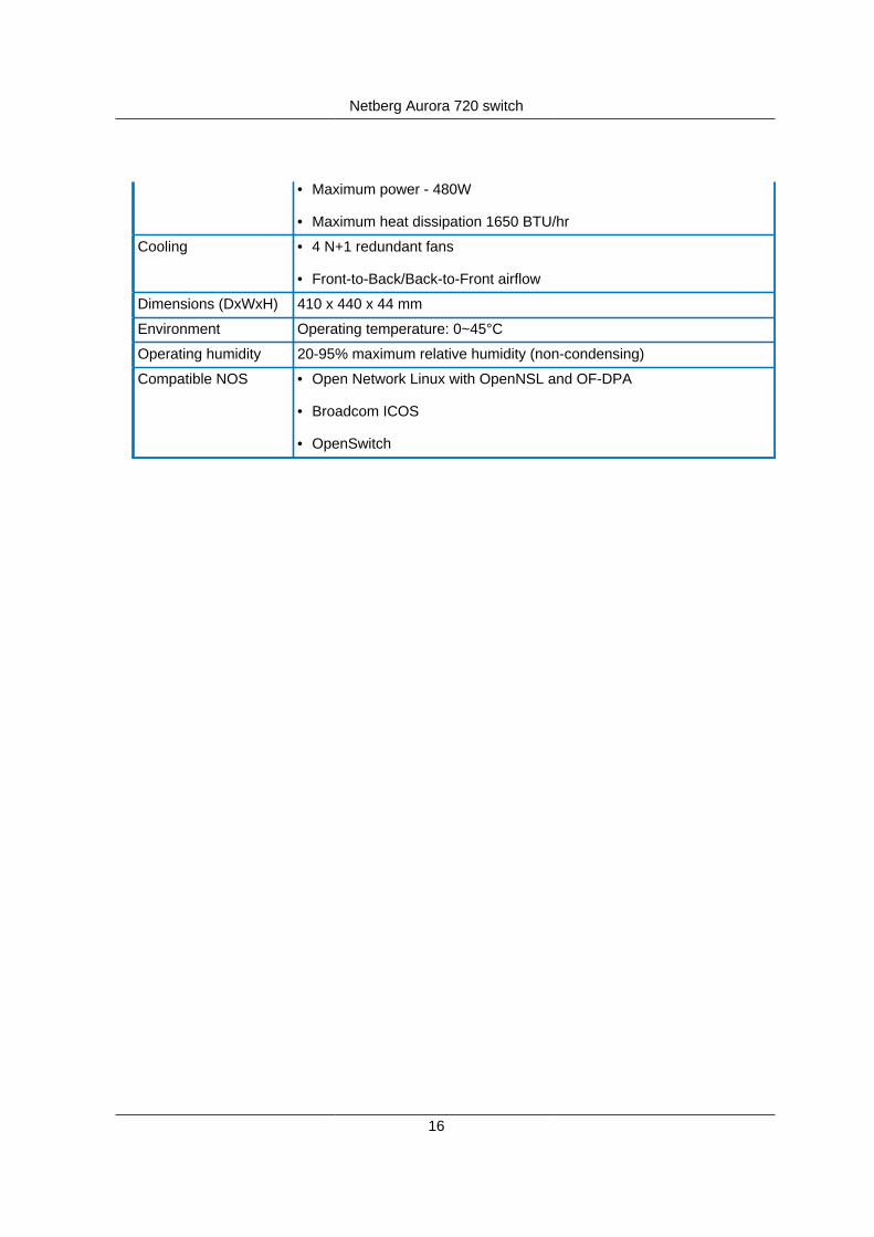
• Maximum power - 480W
• Maximum heat dissipation 1650 BTU/hr
Cooling • 4 N+1 redundant fans
• Front-to-Back/Back-to-Front airflow
Dimensions (DxWxH) 410 x 440 x 44 mm
Environment Operating temperature: 0~45°C
Operating humidity 20-95% maximum relative humidity (non-condensing)
Compatible NOS • Open Network Linux with OpenNSL and OF-DPA
• Broadcom ICOS
• OpenSwitch
Netberg Aurora 720 switch
17
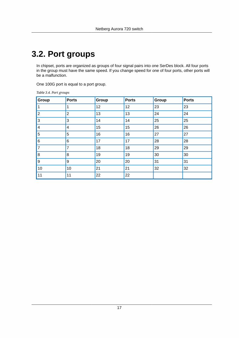
3.2. Port groupsIn chipset, ports are organized as groups of four signal pairs into one SerDes block. All four portsin the group must have the same speed. If you change speed for one of four ports, other ports willbe a malfunction.
One 100G port is equal to a port group.
Table 3.4. Port groups
Group Ports Group Ports Group Ports
1 1 12 12 23 23
2 2 13 13 24 24
3 3 14 14 25 25
4 4 15 15 26 26
5 5 16 16 27 27
6 6 17 17 28 28
7 7 18 18 29 29
8 8 19 19 30 30
9 9 20 20 31 31
10 10 21 21 32 32
11 11 22 22
Netberg Aurora 720 switch
18
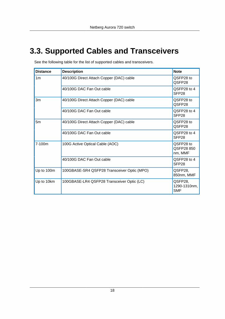
3.3. Supported Cables and TransceiversSee the following table for the list of supported cables and transceivers.
Distance Description Note
40/100G Direct Attach Copper (DAC) cable QSFP28 toQSFP28
1m
40/100G DAC Fan Out cable QSFP28 to 4SFP28
40/100G Direct Attach Copper (DAC) cable QSFP28 toQSFP28
3m
40/100G DAC Fan Out cable QSFP28 to 4SFP28
40/100G Direct Attach Copper (DAC) cable QSFP28 toQSFP28
5m
40/100G DAC Fan Out cable QSFP28 to 4SFP28
100G Active Optical Cable (AOC) QSFP28 toQSFP28 850nm, MMF
7-100m
40/100G DAC Fan Out cable QSFP28 to 4SFP28
Up to 100m 100GBASE-SR4 QSFP28 Transceiver Optic (MPO) QSFP28,850nm, MMF
Up to 10km 100GBASE-LR4 QSFP28 Transceiver Optic (LC) QSFP28,1290-1310nm,SMF
19
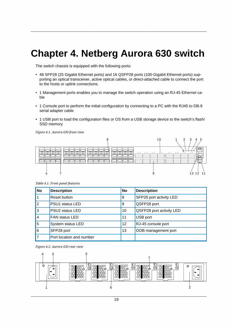
Chapter 4. Netberg Aurora 630 switchThe switch chassis is equipped with the following ports:
• 48 SFP28 (25 Gigabit Ethernet ports) and 16 QSFP28 ports (100-Gigabit Ethernet ports) sup-porting an optical transceiver, active optical cables, or direct-attached cable to connect the portto the hosts or uplink connections.
• 1 Management ports enables you to manage the switch operation using an RJ-45 Ethernet ca-ble
• 1 Console port to perform the initial configuration by connecting to a PC with the RJ45 to DB-9serial adapter cable
• 1 USB port to load the configuration files or OS from a USB storage device to the switch’s flash/SSD memory
Figure 4.1. Aurora 630 front view
58 59 60 61 62 63 64
6 7
8
9
10
111213
RESETPSU1 PSU2 FAN STAT
484746454443
424140393837
363534333231
302928272625
242322212019
181716151413
121110981 2 3
4 5 67
49 50 51 52 53 54 55 56 57
1 2 3 4 5
Table 4.1. Front panel features
No Description No Description
1 Reset button 8 SFP28 port activity LED
2 PSU1 status LED 9 QSFP28 port
3 PSU2 status LED 10 QSFP28 port activity LED
4 FAN status LED 11 USB port
5 System status LED 12 RJ-45 console port
6 SFP28 port 13 OOB management port
7 Port location and number
Figure 4.2. Aurora 630 rear view
EEE E
1
4
2
75
6
3
E

Netberg Aurora 630 switch
20
Table 4.2. Rear panel features
No Description No Description
1 PSU1 5 Hot-swappable FAN module
2 PSU2 6 FAN module screw
3 AC Power Connector (with Plug Retain-er)
7 Fan status LED
4 PSU status LED
Table 4.3. LED function description
LED Function/State Meaning/Control
OFF Power is not supplied to the device
Steady Green PSU is operating normally
Power LED status forPSU1 and PSU2
Amber Possible issues:
• PSU is present, but no AC sup-plied
• Fan Lock
• OTP: Over Temperature Protec-tion
• OCP: Over Current Protection
• OVP: Over Voltage Protection
• UVP: Under Voltage Protection
Green FAN is operating normally.FAN LED status
Steady Amber FAN is fault. Check LED of Fantray in rear panel side to knowwhich one is fault.
Green System function properlySystem LED status
Amber System fail
OFF No link is established on the port.
Steady Green A valid 25Gbps link is established
Blinking Green Packets transmitting/receiving isoccurring at 25Gbps
Steady Yellow A valid 10Gbps link is established
Link/Speed/ACT LEDmode for port 0 to 48
Blinking Yellow Packets transmitting/receiving isoccurring at 10Gbps
OFF No link is established on the port.
Steady Green A valid 100Gbps link is established
Link/Speed/ACT LEDmode for port 49 to 54
Blinking Green Packets transmitting/receiving isoccurring at 100Gbps

Netberg Aurora 630 switch
21
LED Function/State Meaning/Control
Steady Yellow A valid 40Gbps link is established
Blinking Yellow Packets transmitting/receiving isoccurring at 40Gbps

Netberg Aurora 630 switch
22
4.1. SpecificationSystem specification
Ports • 48x 25/10GbE QSFP28 ports in 1 RU
• 16x 100/40GbE QSFP28 ports in 1 RU
• Up to 112x 25/10G SFP28 port via break-out cables
• 1x RJ-45 out-of-band (10/100/1000) management
• 1x RJ-45 console (RS232)
• 1x USB
Front IO • Fan LED
• System status LED
• PSU1 status LED
• PSU2 status LED
• Reset button
Performance • Switching silicon: 3.2Tbps Broadcom Tomahawk BCM56960
• Forwarding rate: 4400Mpps
• Latency: <500 нс (PHY-less)
• Layer 2: 136K MAC addresses, 4K Vlans
• Layer 3: 128K IPv4 host routes, 72K IPv4/36K IPv6 routes, 64KIPv4/32K IPv6 Mroutes
• Redundancy: 256 x 802.3ad groups; 32-way ECMP
• Packet Buffer: 16MB
• Intel® Atom™ Processor C2558
• 8GB DDR3 ECC (up to 16GB)
• 64GB SSD
Power • 650W 1+1 RPSU 80+ Platinum
• 100V-240V AC / 50-60Hz
• 190V-310V DC
• Up to 300 W (full load)
• Typical power - 210W

Netberg Aurora 630 switch
23
• Maximum power - 480W
• Maximum heat dissipation 1650 BTU/hr
Cooling • 5 N+1 redundant fans
• Front-to-Back/Back-to-Front airflow
Dimensions (DxWxH) 410 x 440 x 44 mm
Environment Operating temperature: 0~45°C
Operating humidity 20-95% maximum relative humidity (non-condensing)
Compatible NOS • Open Network Linux with OpenNSL and OF-DPA
• Broadcom ICOS
• OpenSwitch
Netberg Aurora 630 switch
24
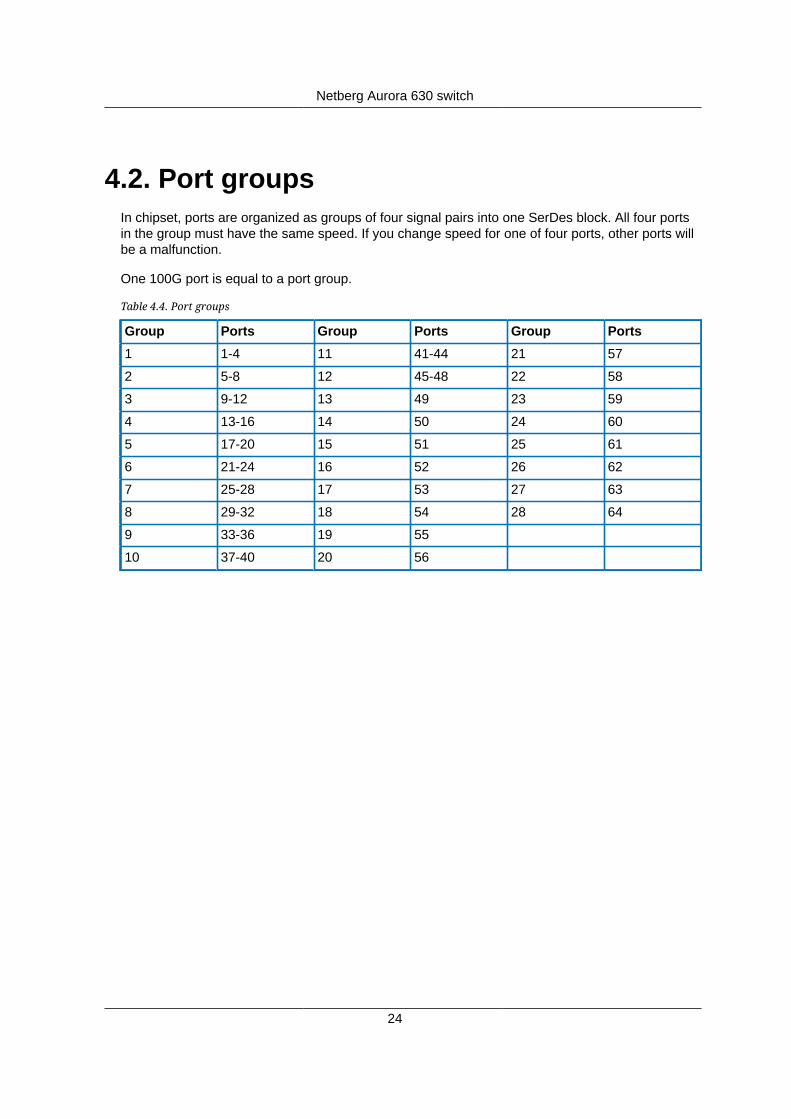
4.2. Port groupsIn chipset, ports are organized as groups of four signal pairs into one SerDes block. All four portsin the group must have the same speed. If you change speed for one of four ports, other ports willbe a malfunction.
One 100G port is equal to a port group.
Table 4.4. Port groups
Group Ports Group Ports Group Ports
1 1-4 11 41-44 21 57
2 5-8 12 45-48 22 58
3 9-12 13 49 23 59
4 13-16 14 50 24 60
5 17-20 15 51 25 61
6 21-24 16 52 26 62
7 25-28 17 53 27 63
8 29-32 18 54 28 64
9 33-36 19 55
10 37-40 20 56
Netberg Aurora 630 switch
25
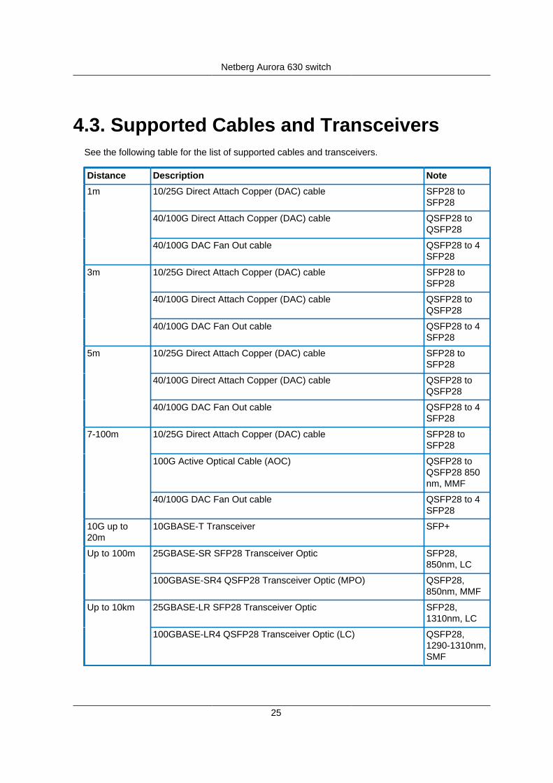
4.3. Supported Cables and TransceiversSee the following table for the list of supported cables and transceivers.
Distance Description Note
10/25G Direct Attach Copper (DAC) cable SFP28 toSFP28
40/100G Direct Attach Copper (DAC) cable QSFP28 toQSFP28
1m
40/100G DAC Fan Out cable QSFP28 to 4SFP28
10/25G Direct Attach Copper (DAC) cable SFP28 toSFP28
40/100G Direct Attach Copper (DAC) cable QSFP28 toQSFP28
3m
40/100G DAC Fan Out cable QSFP28 to 4SFP28
10/25G Direct Attach Copper (DAC) cable SFP28 toSFP28
40/100G Direct Attach Copper (DAC) cable QSFP28 toQSFP28
5m
40/100G DAC Fan Out cable QSFP28 to 4SFP28
10/25G Direct Attach Copper (DAC) cable SFP28 toSFP28
100G Active Optical Cable (AOC) QSFP28 toQSFP28 850nm, MMF
7-100m
40/100G DAC Fan Out cable QSFP28 to 4SFP28
10G up to20m
10GBASE-T Transceiver SFP+
25GBASE-SR SFP28 Transceiver Optic SFP28,850nm, LC
Up to 100m
100GBASE-SR4 QSFP28 Transceiver Optic (MPO) QSFP28,850nm, MMF
25GBASE-LR SFP28 Transceiver Optic SFP28,1310nm, LC
Up to 10km
100GBASE-LR4 QSFP28 Transceiver Optic (LC) QSFP28,1290-1310nm,SMF

26
Chapter 5. Netberg Aurora 620 switchThe switch chassis is equipped with the following ports:
• 48 SFP28 (25 Gigabit Ethernet ports) and 6 QSFP28 ports (100-Gigabit Ethernet ports) support-ing an optical transceiver, active optical cables, or direct-attached cable to connect the port tothe hosts or uplink connections.
• 1 Management ports enables you to manage the switch operation using an RJ-45 Ethernet ca-ble
• 1 Console port to perform the initial configuration by connecting to a PC with the mini-USB toDB-9 serial adapter cable
• 1 USB port to load the configuration files or OS from a USB storage device to the switch’s flash/SSD memory
Figure 5.1. Aurora 620 front view
5453
5251
RESET PSU1 PSU2 FAN STAT
1 2 3 4 5
6 7 8
9
10 11
5049
4847
4645
4443
4241
4039
3837
3635
3433
3231
3029
2827
2625
2423
2221
2019
1817
1615
1413
1211
109
81
23
45
67
1213
Table 5.1. Front panel features
No Description No Description
1 Reset button 8 SFP28 port activity LED
2 PSU1 status LED 9 QSFP28 port
3 PSU2 status LED 10 QSFP28 port activity LED
4 FAN status LED 11 USB port
5 System status LED 12 mini-USB console port
6 SFP28 port 13 OOB management port
7 Port location and number
Figure 5.2. Aurora 620 rear view
EEE E
550W 550W
1 4 2
7
5
6
3

Netberg Aurora 620 switch
27
Table 5.2. Rear panel features
No Description No Description
1 PSU1 5 Hot-swappable FAN module
2 PSU2 6 FAN module screw
3 AC Power Connector (with Plug Retain-er)
7 Fan status LED
4 PSU status LED
Table 5.3. LED function description
LED Function/State Meaning/Control
OFF Power is not supplied to the device
Steady Green PSU is operating normally
Power LED status forPSU1 and PSU2
Amber Possible issues:
• PSU is present, but no AC sup-plied
• Fan Lock
• OTP: Over Temperature Protec-tion
• OCP: Over Current Protection
• OVP: Over Voltage Protection
• UVP: Under Voltage Protection
Green FAN is operating normally.FAN LED status
Steady Amber FAN is fault. Check LED of Fantray in rear panel side to knowwhich one is fault.
Green System function properlySystem LED status
Amber System fail
OFF No link is established on the port.
Steady Green A valid 25Gbps link is established
Blinking Green Packets transmitting/receiving isoccurring at 25Gbps
Steady Yellow A valid 10Gbps link is established
Link/Speed/ACT LEDmode for port 0 to 48
Blinking Yellow Packets transmitting/receiving isoccurring at 10Gbps
OFF No link is established on the port.
Steady Green A valid 100Gbps link is established
Link/Speed/ACT LEDmode for port 49 to 54
Blinking Green Packets transmitting/receiving isoccurring at 100Gbps

Netberg Aurora 620 switch
28
LED Function/State Meaning/Control
Steady Yellow A valid 40Gbps link is established
Blinking Yellow Packets transmitting/receiving isoccurring at 40Gbps
Netberg Aurora 620 switch
29
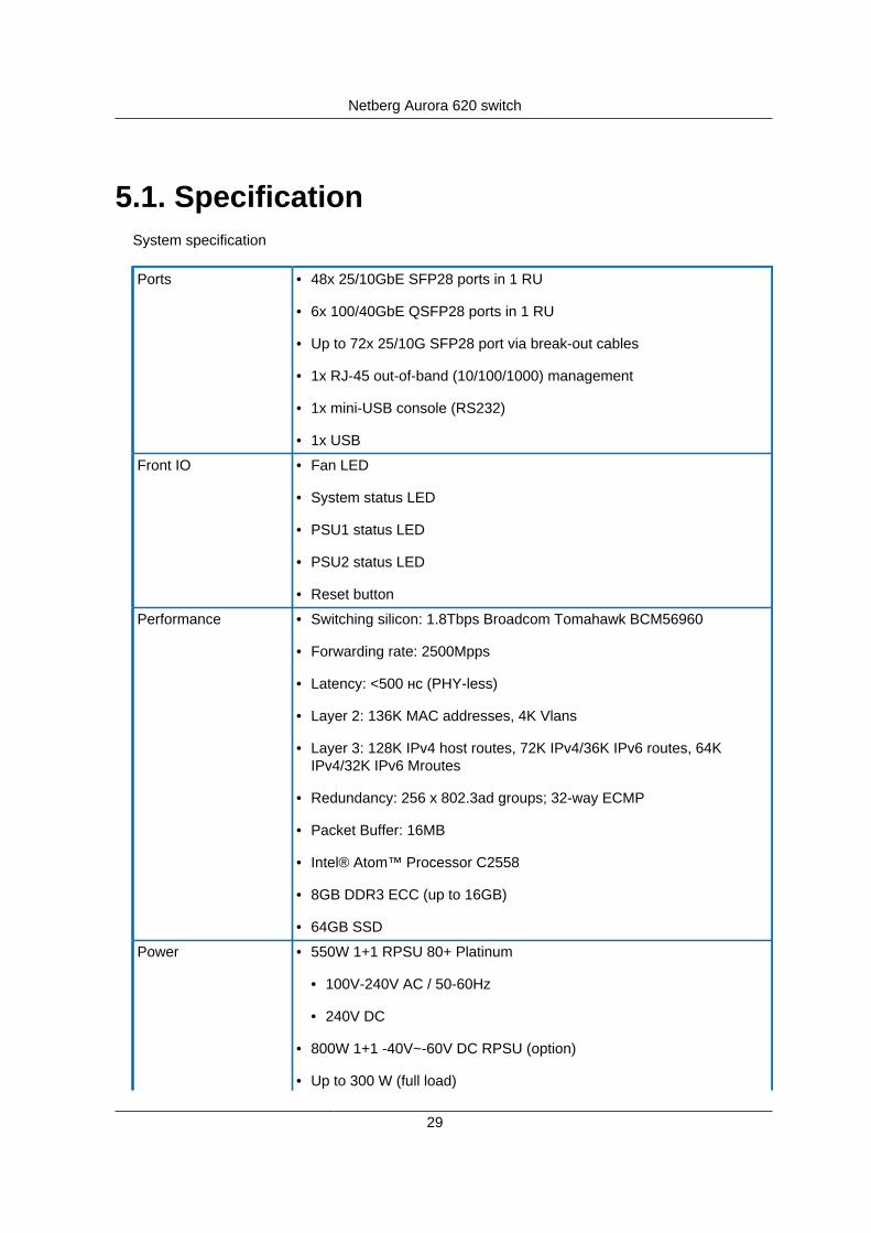
5.1. SpecificationSystem specification
Ports • 48x 25/10GbE SFP28 ports in 1 RU
• 6x 100/40GbE QSFP28 ports in 1 RU
• Up to 72x 25/10G SFP28 port via break-out cables
• 1x RJ-45 out-of-band (10/100/1000) management
• 1x mini-USB console (RS232)
• 1x USB
Front IO • Fan LED
• System status LED
• PSU1 status LED
• PSU2 status LED
• Reset button
Performance • Switching silicon: 1.8Tbps Broadcom Tomahawk BCM56960
• Forwarding rate: 2500Mpps
• Latency: <500 нс (PHY-less)
• Layer 2: 136K MAC addresses, 4K Vlans
• Layer 3: 128K IPv4 host routes, 72K IPv4/36K IPv6 routes, 64KIPv4/32K IPv6 Mroutes
• Redundancy: 256 x 802.3ad groups; 32-way ECMP
• Packet Buffer: 16MB
• Intel® Atom™ Processor C2558
• 8GB DDR3 ECC (up to 16GB)
• 64GB SSD
Power • 550W 1+1 RPSU 80+ Platinum
• 100V-240V AC / 50-60Hz
• 240V DC
• 800W 1+1 -40V~-60V DC RPSU (option)
• Up to 300 W (full load)

Netberg Aurora 620 switch
30
• Typical power - 210W
• Maximum power - 480W
• Maximum heat dissipation 1650 BTU/hr
Cooling • 4 N+1 redundant fans
• Front-to-Back/Back-to-Front airflow
Dimensions (DxWxH) 410 x 440 x 44 mm
Environment Operating temperature: 0~45°C
Operating humidity 20-95% maximum relative humidity (non-condensing)
Compatible NOS • Open Network Linux with OpenNSL and OF-DPA
• Broadcom ICOS
• OpenSwitch
Netberg Aurora 620 switch
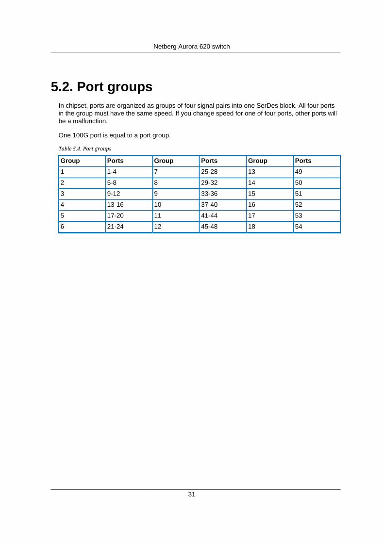
31
5.2. Port groupsIn chipset, ports are organized as groups of four signal pairs into one SerDes block. All four portsin the group must have the same speed. If you change speed for one of four ports, other ports willbe a malfunction.
One 100G port is equal to a port group.
Table 5.4. Port groups
Group Ports Group Ports Group Ports
1 1-4 7 25-28 13 49
2 5-8 8 29-32 14 50
3 9-12 9 33-36 15 51
4 13-16 10 37-40 16 52
5 17-20 11 41-44 17 53
6 21-24 12 45-48 18 54

Netberg Aurora 620 switch
32
5.3. Supported Cables and TransceiversSee the following table for the list of supported cables and transceivers.
Distance Description Note
10/25G Direct Attach Copper (DAC) cable SFP28 toSFP28
40/100G Direct Attach Copper (DAC) cable QSFP28 toQSFP28
1m
40/100G DAC Fan Out cable QSFP28 to 4SFP28
10/25G Direct Attach Copper (DAC) cable SFP28 toSFP28
40/100G Direct Attach Copper (DAC) cable QSFP28 toQSFP28
3m
40/100G DAC Fan Out cable QSFP28 to 4SFP28
10/25G Direct Attach Copper (DAC) cable SFP28 toSFP28
40/100G Direct Attach Copper (DAC) cable QSFP28 toQSFP28
5m
40/100G DAC Fan Out cable QSFP28 to 4SFP28
10/25G Direct Attach Copper (DAC) cable SFP28 toSFP28
100G Active Optical Cable (AOC) QSFP28 toQSFP28 850nm, MMF
7-100m
40/100G DAC Fan Out cable QSFP28 to 4SFP28
10G up to20m
10GBASE-T Transceiver SFP+
25GBASE-SR SFP28 Transceiver Optic SFP28,850nm, LC
Up to 100m
100GBASE-SR4 QSFP28 Transceiver Optic (MPO) QSFP28,850nm, MMF
25GBASE-LR SFP28 Transceiver Optic SFP28,1310nm, LC
Up to 10km
100GBASE-LR4 QSFP28 Transceiver Optic (LC) QSFP28,1290-1310nm,SMF
33
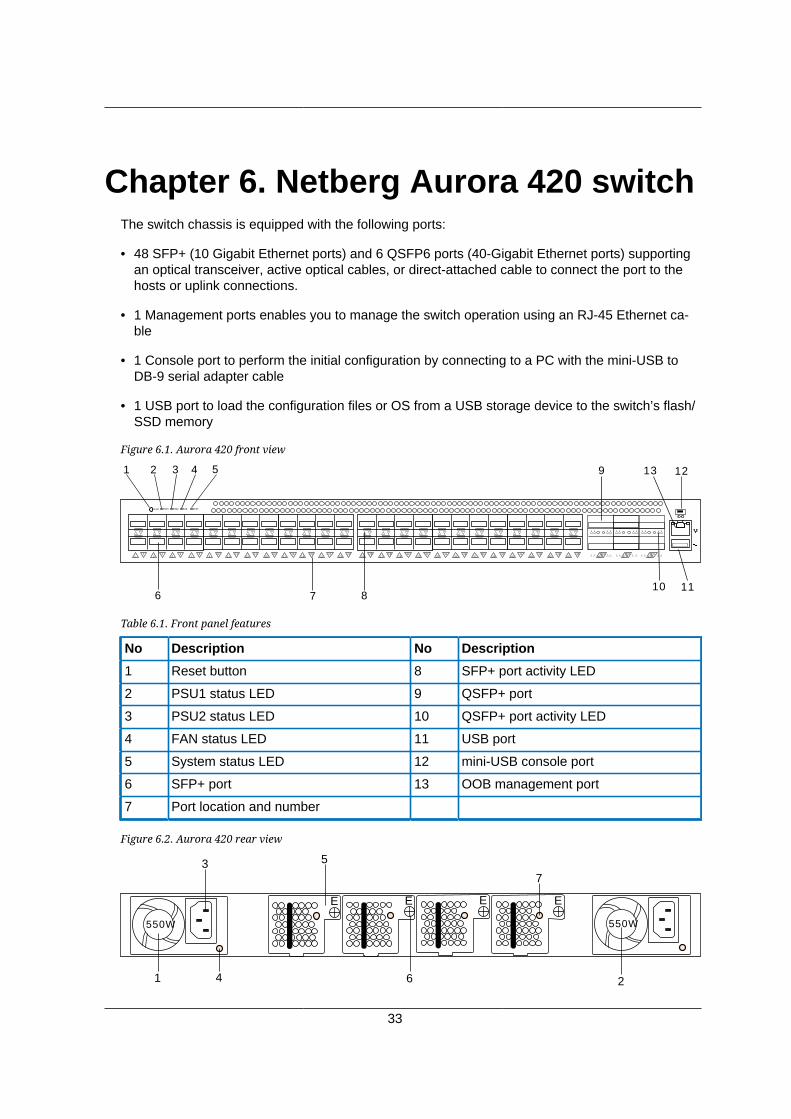
Chapter 6. Netberg Aurora 420 switchThe switch chassis is equipped with the following ports:
• 48 SFP+ (10 Gigabit Ethernet ports) and 6 QSFP6 ports (40-Gigabit Ethernet ports) supportingan optical transceiver, active optical cables, or direct-attached cable to connect the port to thehosts or uplink connections.
• 1 Management ports enables you to manage the switch operation using an RJ-45 Ethernet ca-ble
• 1 Console port to perform the initial configuration by connecting to a PC with the mini-USB toDB-9 serial adapter cable
• 1 USB port to load the configuration files or OS from a USB storage device to the switch’s flash/SSD memory
Figure 6.1. Aurora 420 front view
5453
5251
RESET PSU1 PSU2 FAN STAT
1 2 3 4 5
6 7 8
9
10 11
5049
4847
4645
4443
4241
4039
3837
3635
3433
3231
3029
2827
2625
2423
2221
2019
1817
1615
1413
1211
109
81
23
45
67
1213
Table 6.1. Front panel features
No Description No Description
1 Reset button 8 SFP+ port activity LED
2 PSU1 status LED 9 QSFP+ port
3 PSU2 status LED 10 QSFP+ port activity LED
4 FAN status LED 11 USB port
5 System status LED 12 mini-USB console port
6 SFP+ port 13 OOB management port
7 Port location and number
Figure 6.2. Aurora 420 rear view
EEE E
550W 550W
1 4 2
7
5
6
3
Netberg Aurora 420 switch
34
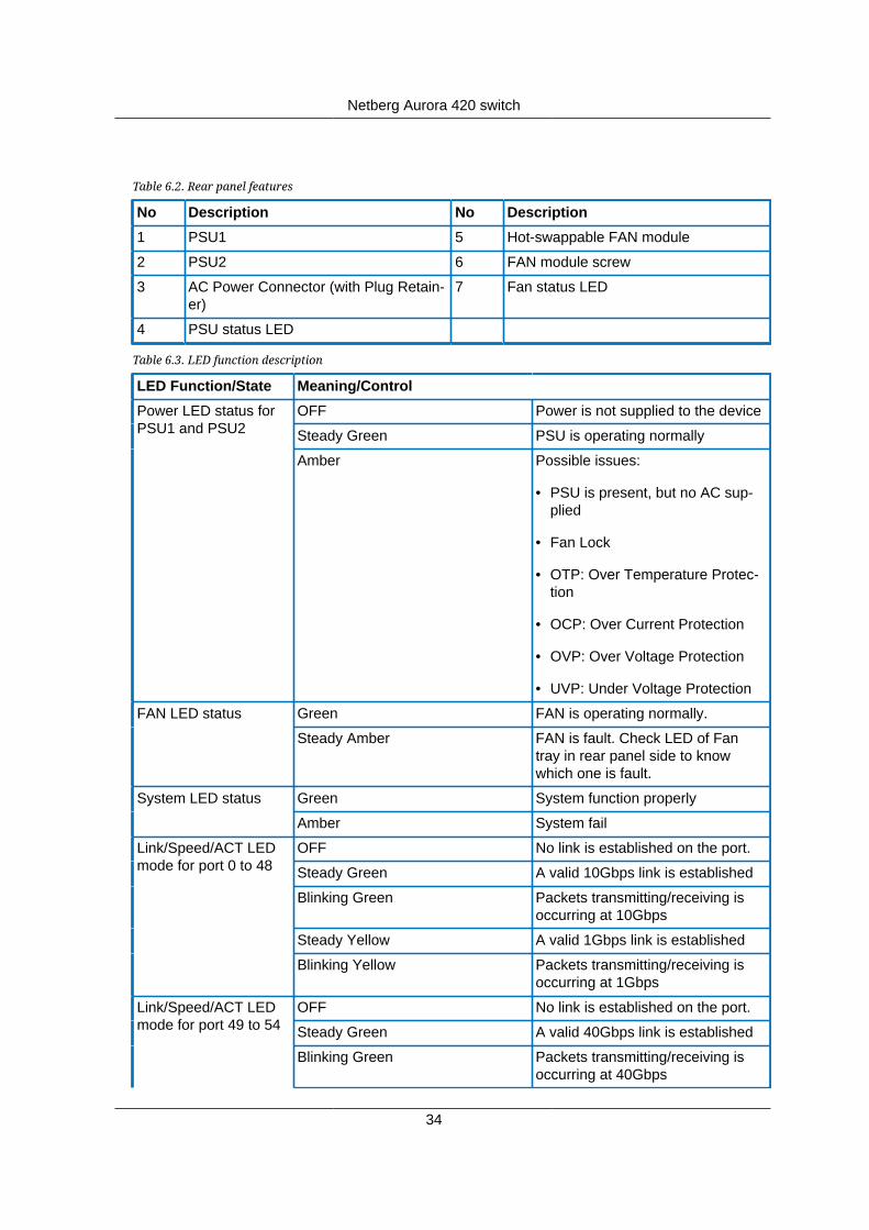
Table 6.2. Rear panel features
No Description No Description
1 PSU1 5 Hot-swappable FAN module
2 PSU2 6 FAN module screw
3 AC Power Connector (with Plug Retain-er)
7 Fan status LED
4 PSU status LED
Table 6.3. LED function description
LED Function/State Meaning/Control
OFF Power is not supplied to the device
Steady Green PSU is operating normally
Power LED status forPSU1 and PSU2
Amber Possible issues:
• PSU is present, but no AC sup-plied
• Fan Lock
• OTP: Over Temperature Protec-tion
• OCP: Over Current Protection
• OVP: Over Voltage Protection
• UVP: Under Voltage Protection
Green FAN is operating normally.FAN LED status
Steady Amber FAN is fault. Check LED of Fantray in rear panel side to knowwhich one is fault.
Green System function properlySystem LED status
Amber System fail
OFF No link is established on the port.
Steady Green A valid 10Gbps link is established
Blinking Green Packets transmitting/receiving isoccurring at 10Gbps
Steady Yellow A valid 1Gbps link is established
Link/Speed/ACT LEDmode for port 0 to 48
Blinking Yellow Packets transmitting/receiving isoccurring at 1Gbps
OFF No link is established on the port.
Steady Green A valid 40Gbps link is established
Link/Speed/ACT LEDmode for port 49 to 54
Blinking Green Packets transmitting/receiving isoccurring at 40Gbps

Netberg Aurora 420 switch
35
LED Function/State Meaning/Control
Steady Yellow A valid 10Gbps link is established
Blinking Yellow Packets transmitting/receiving isoccurring at 10Gbps

Netberg Aurora 420 switch
36
6.1. SpecificationSystem specification
Ports • 48x 10/1GbE SFP+ ports in 1 RU
• 6x 40GbE QSFP+ ports in 1 RU
• Up to 72x 10/1G SFP+ port via break-out cables
• 1x RJ-45 out-of-band (10/100/1000) management
• 1x mini-USB console (RS232)
• 1x USB
Front IO • Fan LED
• System status LED
• PSU1 status LED
• PSU2 status LED
• Reset button
Performance • Switching silicon: 1.8Tbps Broadcom Trident2 BCM56854
• Forwarding rate: 1071Mpps
• Latency: <700 нс (PHY-less)
• MAC table: Unified Forwarding Table (UFT)
• Redundancy: 256 x 802.3ad groups; 32-way ECMP
• Packet Buffer: 12MB
• Intel® Atom™ Processor C2558
• 8GB DDR3 ECC (up to 16GB)
• 64GB SSD
Power • 550W 1+1 RPSU 80+ Platinum
• 100V-240V AC / 50-60Hz
• 240V DC
• 800W 1+1 -40V~-60V DC RPSU (option)
• Up to 190 W (full load)
• Typical power - 210W
Netberg Aurora 420 switch
37
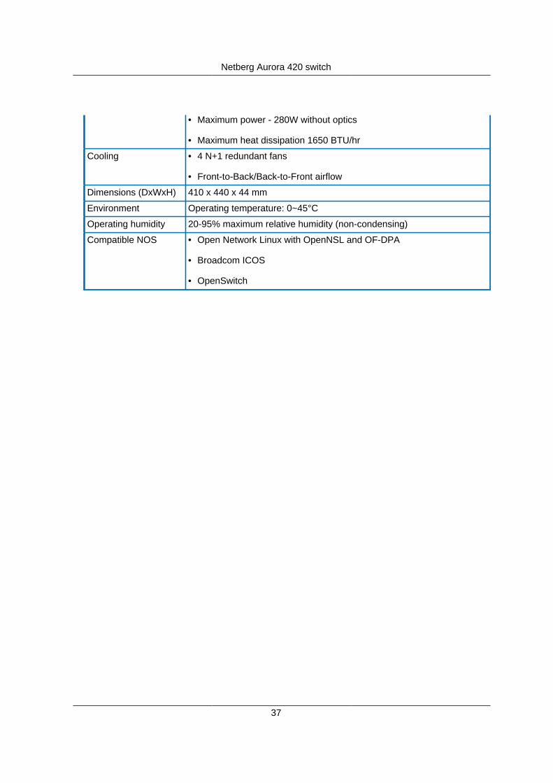
• Maximum power - 280W without optics
• Maximum heat dissipation 1650 BTU/hr
Cooling • 4 N+1 redundant fans
• Front-to-Back/Back-to-Front airflow
Dimensions (DxWxH) 410 x 440 x 44 mm
Environment Operating temperature: 0~45°C
Operating humidity 20-95% maximum relative humidity (non-condensing)
Compatible NOS • Open Network Linux with OpenNSL and OF-DPA
• Broadcom ICOS
• OpenSwitch

Netberg Aurora 420 switch
38
6.2. Supported Cables and TransceiversSee the following table for the list of supported cables and transceivers.
Distance Description Note
10G Direct Attach Copper (DAC) cable SFP+ to SFP+
40G Direct Attach Copper (DAC) cable QSFP+ toQSFP+
1m
40G DAC Fan Out cable QSFP+ to 4SFP+
10G Direct Attach Copper (DAC) cable SFP+ to SFP+
40G Direct Attach Copper (DAC) cable QSFP+ toQSFP+
3m
40G DAC Fan Out cable QSFP+ to 4SFP+
10/25G Direct Attach Copper (DAC) cable SFP+ to SFP+
40G Direct Attach Copper (DAC) cable QSFP+ toQSFP+
5m
40G DAC Fan Out cable QSFP+ to 4SFP+
10G Direct Attach Copper (DAC) cable SFP+ to SFP+
40G Active Optical Cable (AOC) QSFP+ toQSFP+ 850nm, MMF
7-100m
40G DAC Fan Out cable QSFP+ to 4SFP+
1G 1000BASE-SX, 1000BASE-LX, 100/1000BASE-T TransceiverOptic
SFP
10GBASE-SR SFP+ Transceiver Optic SFP+, 850nm,LC
Up to100/300m
40GBASE-SR4 QSFP+ Transceiver Optic (MPO) QSFP+,850nm, MMF
10GBASE-LR SFP+ Transceiver Optic SFP+,1310nm, LC
Up to 10km
40GBASE-LR4 QSFP+ Transceiver Optic (LC) QSFP+,1290-1310nm,SMF
39
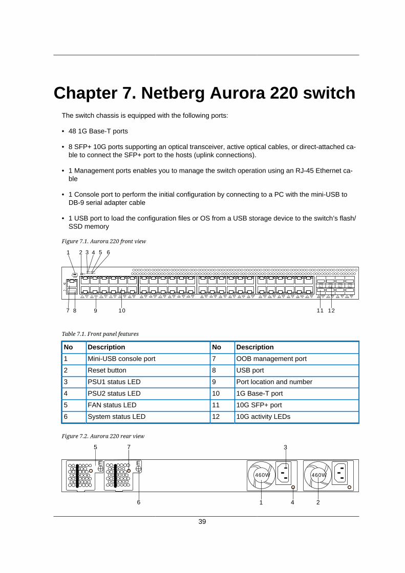
Chapter 7. Netberg Aurora 220 switchThe switch chassis is equipped with the following ports:
• 48 1G Base-T ports
• 8 SFP+ 10G ports supporting an optical transceiver, active optical cables, or direct-attached ca-ble to connect the SFP+ port to the hosts (uplink connections).
• 1 Management ports enables you to manage the switch operation using an RJ-45 Ethernet ca-ble
• 1 Console port to perform the initial configuration by connecting to a PC with the mini-USB toDB-9 serial adapter cable
• 1 USB port to load the configuration files or OS from a USB storage device to the switch’s flash/SSD memory
Figure 7.1. Aurora 220 front view
4847
4645
4443
4241
4039
3837
3635
3433
3231
3029
2827
2625
2423
2221
2019
1817
1615
1413
1211
109
81
23
45
67
RESET
PSU1
PSU2
FAN
STAT
5049
5251
5453
5655
1 2 3 4 5 6
7 8 9 10 11 12
Table 7.1. Front panel features
No Description No Description
1 Mini-USB console port 7 OOB management port
2 Reset button 8 USB port
3 PSU1 status LED 9 Port location and number
4 PSU2 status LED 10 1G Base-T port
5 FAN status LED 11 10G SFP+ port
6 System status LED 12 10G activity LEDs
Figure 7.2. Aurora 220 rear view
EE
460W 460W
1 4 2
75
6
3
Netberg Aurora 220 switch
40
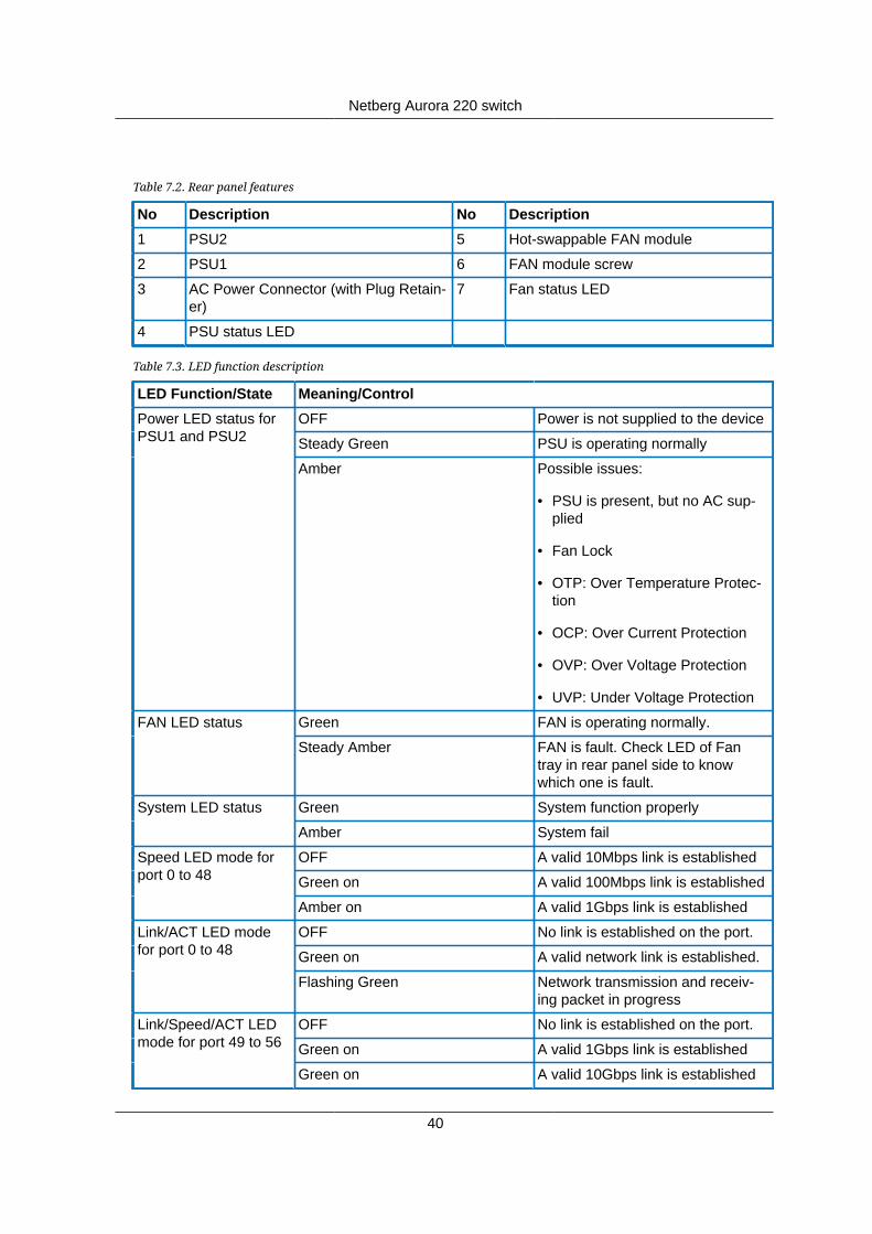
Table 7.2. Rear panel features
No Description No Description
1 PSU2 5 Hot-swappable FAN module
2 PSU1 6 FAN module screw
3 AC Power Connector (with Plug Retain-er)
7 Fan status LED
4 PSU status LED
Table 7.3. LED function description
LED Function/State Meaning/Control
OFF Power is not supplied to the device
Steady Green PSU is operating normally
Power LED status forPSU1 and PSU2
Amber Possible issues:
• PSU is present, but no AC sup-plied
• Fan Lock
• OTP: Over Temperature Protec-tion
• OCP: Over Current Protection
• OVP: Over Voltage Protection
• UVP: Under Voltage Protection
Green FAN is operating normally.FAN LED status
Steady Amber FAN is fault. Check LED of Fantray in rear panel side to knowwhich one is fault.
Green System function properlySystem LED status
Amber System fail
OFF A valid 10Mbps link is established
Green on A valid 100Mbps link is established
Speed LED mode forport 0 to 48
Amber on A valid 1Gbps link is established
OFF No link is established on the port.
Green on A valid network link is established.
Link/ACT LED modefor port 0 to 48
Flashing Green Network transmission and receiv-ing packet in progress
OFF No link is established on the port.
Green on A valid 1Gbps link is established
Link/Speed/ACT LEDmode for port 49 to 56
Green on A valid 10Gbps link is established
Netberg Aurora 220 switch
41
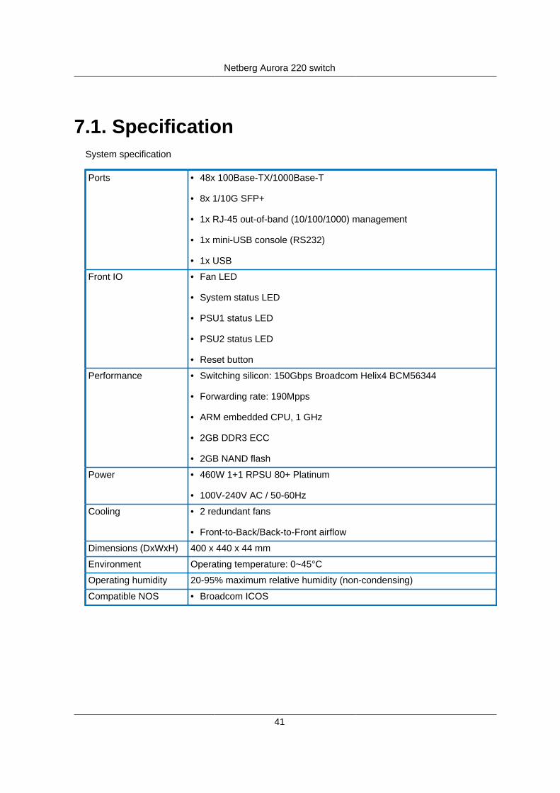
7.1. SpecificationSystem specification
Ports • 48x 100Base-TX/1000Base-T
• 8x 1/10G SFP+
• 1x RJ-45 out-of-band (10/100/1000) management
• 1x mini-USB console (RS232)
• 1x USB
Front IO • Fan LED
• System status LED
• PSU1 status LED
• PSU2 status LED
• Reset button
Performance • Switching silicon: 150Gbps Broadcom Helix4 BCM56344
• Forwarding rate: 190Mpps
• ARM embedded CPU, 1 GHz
• 2GB DDR3 ECC
• 2GB NAND flash
Power • 460W 1+1 RPSU 80+ Platinum
• 100V-240V AC / 50-60Hz
Cooling • 2 redundant fans
• Front-to-Back/Back-to-Front airflow
Dimensions (DxWxH) 400 x 440 x 44 mm
Environment Operating temperature: 0~45°C
Operating humidity 20-95% maximum relative humidity (non-condensing)
Compatible NOS • Broadcom ICOS
Netberg Aurora 220 switch
42
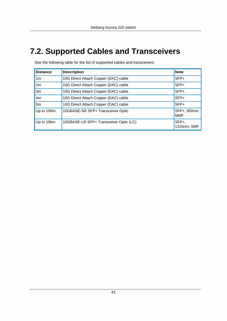
7.2. Supported Cables and TransceiversSee the following table for the list of supported cables and transceivers.
Distance Description Note
1m 10G Direct Attach Copper (DAC) cable SFP+
2m 10G Direct Attach Copper (DAC) cable SFP+
3m 10G Direct Attach Copper (DAC) cable SFP+
4m 10G Direct Attach Copper (DAC) cable SFP+
5m 10G Direct Attach Copper (DAC) cable SFP+
Up to 100m 10GBASE-SR SFP+ Transceiver Optic SFP+, 850nm,MMF
Up to 10km 10GBASE-LR SFP+ Transceiver Optic (LC) SFP+,1310nm, SMF

43
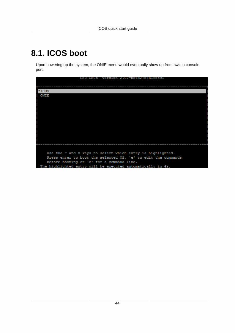
Chapter 8. ICOS quick start guideOn Aurora 220, ICOS is running as standalone NOS, booting right into CLI interface.
On Aurora 720, ICOS is running as an application on top of Linux. To get access to CLI you needto perform several steps below.
ICOS quick start guide
44
8.1. ICOS bootUpon powering up the system, the ONIE menu would eventually show up from switch consoleport.
ICOS quick start guide
45
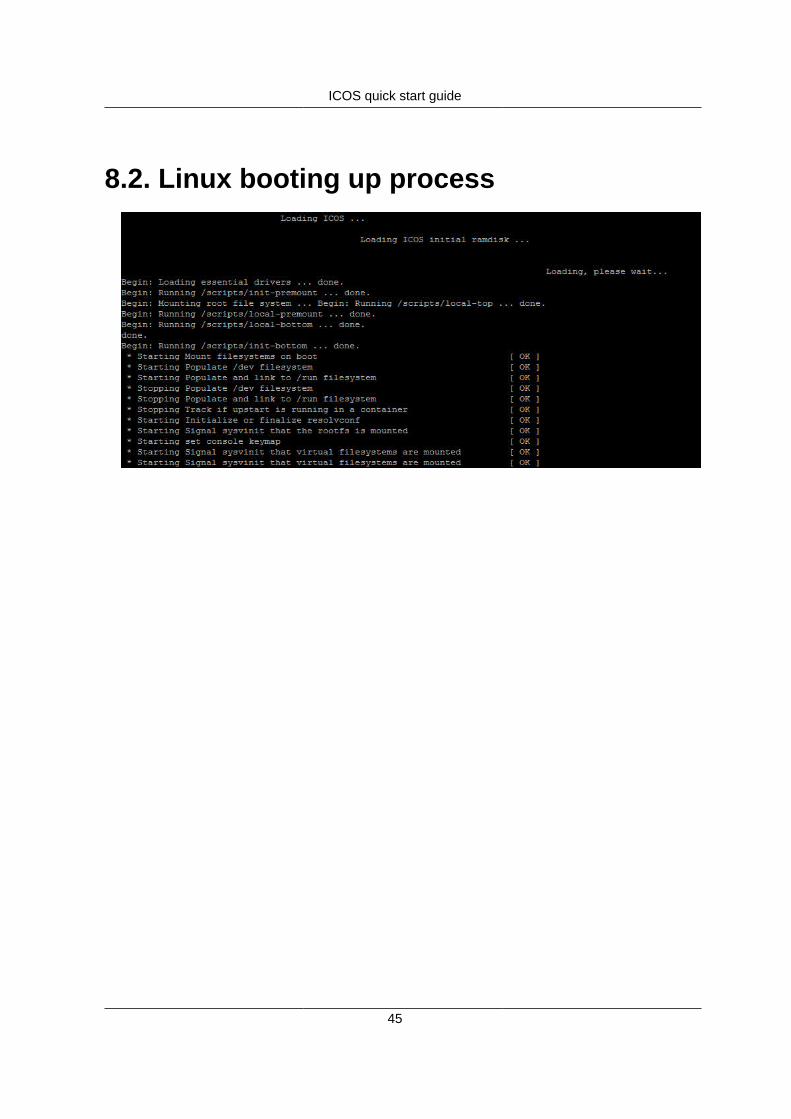
8.2. Linux booting up process
ICOS quick start guide
46
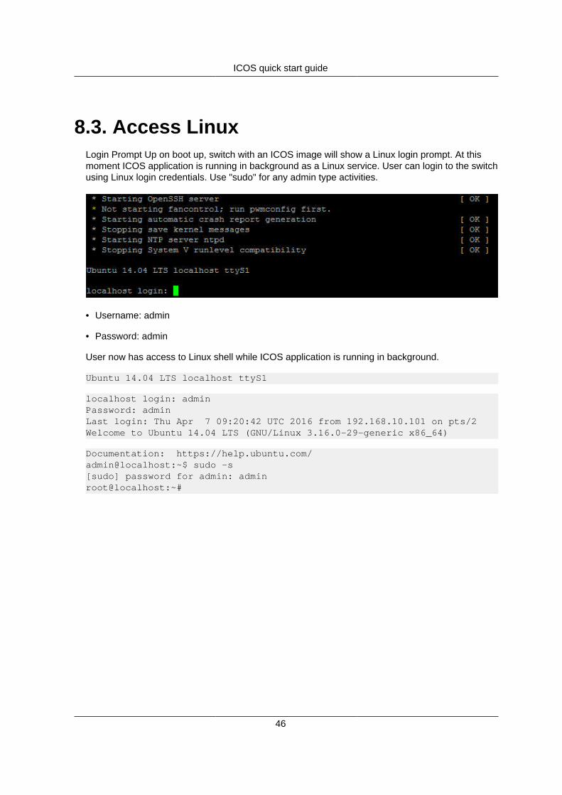
8.3. Access LinuxLogin Prompt Up on boot up, switch with an ICOS image will show a Linux login prompt. At thismoment ICOS application is running in background as a Linux service. User can login to the switchusing Linux login credentials. Use "sudo" for any admin type activities.
• Username: admin
• Password: admin
User now has access to Linux shell while ICOS application is running in background.
Ubuntu 14.04 LTS localhost ttyS1
localhost login: adminPassword: adminLast login: Thu Apr 7 09:20:42 UTC 2016 from 192.168.10.101 on pts/2Welcome to Ubuntu 14.04 LTS (GNU/Linux 3.16.0-29-generic x86_64)
Documentation: https://help.ubuntu.com/admin@localhost:~$ sudo -s[sudo] password for admin: adminroot@localhost:~#
ICOS quick start guide
47
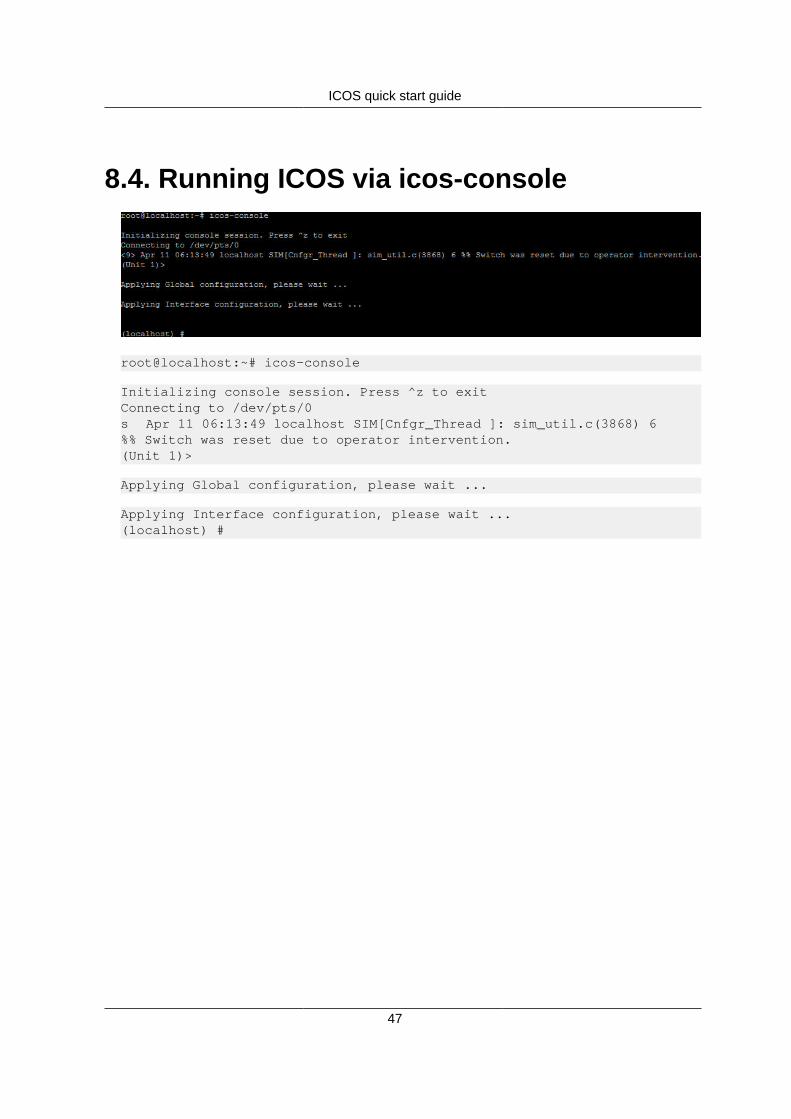
8.4. Running ICOS via icos-console
root@localhost:~# icos-console
Initializing console session. Press ^z to exitConnecting to /dev/pts/0s Apr 11 06:13:49 localhost SIM[Cnfgr_Thread ]: sim_util.c(3868) 6%% Switch was reset due to operator intervention.(Unit 1)>
Applying Global configuration, please wait ...
Applying Interface configuration, please wait ...(localhost) #

ICOS quick start guide
48
8.5. Running ICOS via icos-cliroot@localhost:~# icos-cliInitializing console session. Press ^z to exit.(localhost) #
root@localhost:~# icos-cli -h
Usage: icos-cli [-f<session-id>] [-s] [-h]This command opens a connection to icos and provides CLI access to theuser.If icos service is not running, this command will wait for service tostart.User can come out of the command by pressing ^z at any point of time.
COMMAND LINE OPTIONS
-f<Session-id>Detect and close if particular session already open. The command option also creates a new session.
-sDisplays existing sessions.
-hHelp. Prints this text.
root@localhost:~#

ICOS quick start guide
49
8.6. How to login ICOS via Linux SSHDue to the way that x86 ICOS operates, the service port related commands were be-ing removed; user should configure the service port via Linux prompt on Eth0 port.
1. Login the switch Linux in console
Ubuntu 14.04 LTS localhost ttyS1
localhost login: adminPassword: adminLast login: Thu Apr 7 09:20:42 UTC 2016 from 192.168.10.101 on pts/2Welcome to Ubuntu 14.04 LTS (GNU/Linux 3.16.0-29-generic x86_64)
Documentation: https://help.ubuntu.com/admin@localhost:~$ sudo -s[sudo] password for admin: adminroot@localhost:~#root@localhost:~# ifconfig eth0eth0 Link encap:Ethernet HWaddr 00:05:64:2f:3c:7c inet addr:192.168.0.73 Bcast:192.168.0.255 Mask:255.255.255.0 inet6 addr: fe80::205:64ff:fe2f:3c7c/64 Scope:Link UP BROADCAST RUNNING MULTICAST MTU:1500 Metric:1 RX packets:517 errors:0 dropped:0 overruns:0 frame:0 TX packets:116 errors:0 dropped:0 overruns:0 carrier:0 collisions:0 txqueuelen:1000 RX bytes:39588 (39.5 KB) TX bytes:8936 (8.9 KB)
root@localhost:~#
2. Login the switch Linux via SSH
3. Run ICOS
root@localhost:~# icos-cli

ICOS quick start guide
50
Initializing console session. Press ^z to exit.(localhost) #

ICOS quick start guide
51
8.7. How to reload ICOSThis command resets the ICOS application without powering system off.
(localhost) #(localhost) #reloadThe system has unsaved changes.Would you like to save them now? (y/n) nConfiguration Not Saved!Are you sure you would like to reset the system? (y/n) yReference platform resetting ...Console session closed by foreign host.root@localhost:~#

ICOS quick start guide
52
8.8. How to reload OSThis command enables the user to boot system back into ONIE menu.
(localhost) #reload os
WARNING: All configuration will be lost.Are you sure you would like to reload the network operating system? (y/n) y
!!!!!!!!!!!!!!!! WARNING !!!!!!!!!!!!!!!!! You are about to remove existing icos operating system image.! All system data will be lost and cannot be recovered.
Updating ONIE GRUB configuration to reinstall icos OSReboot for changes to take effect
Broadcast message from root@localhost (/dev/ptmx) at 7:04 ...
The system is going down for reboot NOW!Reference platform resetting ...