the australian national university web based operator...
TRANSCRIPT

The Australian National University
WWeebb BBaasseedd OOppeerraattoorr IInntteerrffaaccee ffoorr aann UUnnddeerrwwaatteerr RRoobboott
By
Sunil Rao(3073691)
A thesis submitted in partial fulfilment of the requirements for the degree ofBachelor of Engineering
June 2000
Supervisors
Mr. Samer Abdallah (FEIT)Dr. David Wettergreen (RSISE)
Prof. Alexander Zelinsky (RSISE)
RSISE – Research School of Information Sciences and Engineering, Australian National UniversityFEIT – Faculty of Engineering and Information Technology, Australian National University

AACCKKNNOOWWLLEEDDGGEEMMEENNTTSS
The author wishes to thank Alex Zelinsky, Samer Abdallah and David Wettergreen for giving
me the opportunity to work on this project as well as for their continuous assistance and
guidance throughout the project.
Thanks to Chris Gaskett and Chanop Silpa-Anan for their help, ideas and tips on various
aspects of the project. Big thanks also to Peter Brown for his help in establishing the
connection to Kambara and communicating with it. I do not believe that I would have been
able to make much progress without their assistance.
I also wish to thank Seungjun Oh, Matthew Bryant, Harley Truong, Jordan Cvetanovski,
Colin Thomsen and Orson Sutherland for their excellent company, their ideas, motivation and
help when things were not going smoothly. Thanks to Colin and Matthew again for the lively
games of chess.
Thanks also to Arvind Venkataraman and Chaitanya Kuber for proof reading my thesis and
providing me with valuable comments. Thanks to my sister Sneha as well for her help
throughout these last four months. And finally to my parents – thanks for your
encouragement and understanding through these last four months. Could not have done it
without you.

AABBSSTTRRAACCTT
This thesis examines the continued development of the operator interface for Kambara, anAutonomous Underwater Vehicle being developed at the ANU. The interface receives stateinformation from the robot and presents it to the operator in intuitive graphicalrepresentations. It is also supposed to provide means for the operator to send commands tothe robot.
The project goal was to develop a web-based interface that would provide adequate guidancefor the robot to perform useful tasks. To this end, the project has developed a system that canbe executed on a web browser such as Netscape.
The system developed also aids direct teleoperation of the robot through the use of a softwarejoystick for manipulating the five degrees of freedom of the AUV. The redesign of theexisting GUI has aided the process by having the camera controls in constant view of theoperator. An investigation has also been conducted regarding the use of VRML 3D modelsfor better visualisation of the rotation and translation state of the robot.
The system uses RMI communication methods in Java 2 to develop cross-networkcapabilities. The current network design conforms to the long-term goal defined for theinterface. The interface receives telemetry router data in real time from the robot. The updateof the GUI is at the rate of 1.24 Hz if the server is located on the system but 6.58 Hz if theserver is on a separate machine. In an ideal Ethernet environment with no traffic the valuesare 3.5 Hz with the server on the system and 9.57 Hz when the server is on a separatemachine.
Camera commands have also been developed for the client and can be sent to the camera on-board Kambara. These were tested using a Sony D-230 camera, which was located on-boardas well as off-board Kambara during various stages of implementation and testing.Enhancement of the existing control system has also been achieved with progress made in thedevelopment of teleoperation and individual control.

Page I
GGLLOOSSSSAARRYY
3D – Three Dimensional
ANU – The Australian National University
API – Application Programming Interface
Applet – A program that is designed to be run using a Web browser
Application – A program that is run from a command line
AUV – Autonomous Underwater Vehicle
Double – A "primitive" Java datatype that represents a 64-bit floating-point value
(IEEE 754- 1985)
GUI – Graphical User Interface
JDK – Java Developers Kit
JVM – Java Virtual Machine
Long – Another "primitive" datatype representing a 32-bit floating-point value
(IEEE 754-1985)
NCSA – National Centre for Supercomputing Applications, University of Illinois, USA
Packet – Bundle of information that is sent across a network connection. It is the simplest
form of a data unit that carries the address of the destination and the data that is to
be sent to that destination
RMI – Remote Method Invocation
RSISE – Research School of Information Sciences and Engineering, ANU
TCP / IP – Transmission Control Protocol / Internet Protocol. A connection-oriented
approach of communication between entities
Thread – Objects that are used to have more than one set of operations executing in the same
program at one time.
UDP – User Datagram Protocol. A connectionless approach of transmitting data between
entities
VRML – Virtual Resource Modelling Language

Page II
LLIISSTT OOFF FFIIGGUURREESS
Figure 1: Life on the Great Barrier Reef 1
Figure 2 Kambara 2
Figure 3: Kambara Software Architecture 3
Figure 4: Original GUI Software Architecture 7
Figure 5: Current GUI Software Architecture 10
Figure 6: ThreeDFrame 11
Figure 7: Camera Panel 12
Figure 8: Data Panel (combines Raw and Derived Data) 13
Figure 9: Kambara Applet Software Architecture 14
Figure 10: Kambara Wavefront Model 15
Figure 11: VRML Model 16
Figure 12: Robot Navigation Controls (1999) 18
Figure 13: NavigationPanel Software Architecture 19
Figure 14: Top View of Kambara 20
Figure 15: Simulation of the movements of the joystick (in the 3D model) 20
Figure 16: Side View of Kambara 21
Figure 17: Current Translations and Rotations 21
Figure 18: Original Network Design 24
Figure 19: Long-Term Goal for Network Design 27
Figure 20: Current Interface Network Design 28
Figure 21: Kambara Applet 31
Figure 22: Co-ordinate System (Kambara and Joystick Panels) 32
Figure 23: Relative movements in the TopPanel and the SidePanel 33
Figure 24: Sony D-230 Camera 38
Figure 25: Sony Camera on-board Kambara 39

Page i
TTAABBLLEE OOFF CCOONNTTEENNTTSS
GLOSSARY...............................................................................................................................I
LIST OF FIGURES................................................................................................................. II
CHAPTER 1: INTRODUCTION ........................................................................................... 1
1.1 Description and Contribution........................................................................................... 2
1.1.1 Kambara Software Architecture ............................................................................. 2
1.1.2 Project Goals........................................................................................................... 3
1.2 Thesis Outline ................................................................................................................... 4
CHAPTER 2: GUI ANALYSIS AND DESIGN..................................................................... 6
2.1 Background....................................................................................................................... 6
2.2 GUI Layout....................................................................................................................... 8
2.2.1 Design Principles .................................................................................................... 8
2.2.2 Software Architecture............................................................................................. 9
2.3 Applet.............................................................................................................................. 14
2.3.1 Software Architecture........................................................................................... 14
2.4 VRML Model of Kambara .............................................................................................. 15
2.4.1 Loading Problems................................................................................................. 16
2.5 Chapter Summary........................................................................................................... 16
CHAPTER 3: SOFTWARE JOYSTICK............................................................................. 17
3.1 Control Modes ................................................................................................................ 17
3.1.1 Observer Mode ..................................................................................................... 17
3.1.2 Individual Control Mode ...................................................................................... 17
3.1.3 Teleoperation Mode.............................................................................................. 18
3.1.4 Supervisory Control Mode ................................................................................... 18
3.2 Requirements and Analysis............................................................................................. 18
3.3 Design ............................................................................................................................. 19
3.3.1 Considerations ...................................................................................................... 19
3.3.2 Software Architecture........................................................................................... 19
3.4 Chapter Summary........................................................................................................... 22

Table of Contents
Page ii
CHAPTER 4: NETWORK ANALYSIS AND DESIGN..................................................... 23
4.1 Background..................................................................................................................... 23
4.1.1 Server.................................................................................................................... 23
4.1.2 Client..................................................................................................................... 24
4.2 Requirements and Analysis............................................................................................. 25
4.2.1 Camera Commands............................................................................................... 25
4.2.2 Telemetry Router .................................................................................................. 26
4.3 Design ............................................................................................................................. 27
4.3.1 Long Term Goal for Network Design................................................................... 27
4.3.2 Conformance to Long-term Goal.......................................................................... 28
4.4 Chapter Summary........................................................................................................... 29
CHAPTER 5: IMPLEMENTATION ................................................................................... 30
5.1 GUI Layout..................................................................................................................... 30
5.2 Applet.............................................................................................................................. 31
5.1.1 Java Plug-In for Web Browsers............................................................................ 31
5.1.2 HTML Conversion................................................................................................ 32
5.3 Software Joystick ............................................................................................................ 32
5.3.1 Co-ordinate System............................................................................................... 32
5.3.2 Rotation Angles and Quaternions ......................................................................... 33
5.3.3 Manipulations using MovementsPanel................................................................. 34
5.4 Networking ..................................................................................................................... 34
5.4.1 Data Interpretation................................................................................................ 34
5.4.2 Conversion to Bytes.............................................................................................. 34
5.5 Control Modes ................................................................................................................ 35
5.6 Chapter Summary........................................................................................................... 36
CHAPTER 6: VALIDATION AND VERIFICATION....................................................... 37
6.1 Testing Procedures ......................................................................................................... 37
6.2 GUI................................................................................................................................. 37
6.3 Applet.............................................................................................................................. 38
6.4 Software Joystick ............................................................................................................ 38
6.5 Communication with Kambara ...................................................................................... 38
6.5.1 Camera Commands............................................................................................... 38

Table of Contents
Page iii
6.5.2 Telemetry Router Data ......................................................................................... 39
6.6 Control Modes ................................................................................................................ 40
6.7 Chapter Summary........................................................................................................... 40
CHAPTER 7: CONCLUSION AND FURTHER WORK.................................................. 41
7.1 Conclusion ...................................................................................................................... 41
7.2 Contributions.................................................................................................................. 41
7.3 Further Work .................................................................................................................. 42
7.2.1 Video Feed............................................................................................................ 42
7.2.2 Supervisory Control.............................................................................................. 42
7.2.3 Network Architecture ........................................................................................... 42
7.2.4 Logging information............................................................................................. 43
BIBLIOGRAPHY................................................................................................................... 44
APPENDIX A: NCSA PORTFOLIO.................................................................................... 45
APPENDIX B: USER DATAGRAM PROTOCOL............................................................ 47
APPENDIX C: VECTOR OF SIMULATOR DATA.......................................................... 48
APPENDIX D: SOFTWARE JOYSTICK DESIGN........................................................... 49
APPENDIX E1: SCREENSHOT OF TELEMETRYPANEL............................................ 50
APPENDIX E2: SCREENSHOT OF POSITIONPANEL.................................................. 51
APPENDIX E3: SCREENSHOT OF DATAPANEL.......................................................... 52
APPENDIX E4: SCREENSHOT OF MESSAGESPANEL............................................... 53
APPENDIX E5: SCREENSHOT OF NAVIGATIONPANEL........................................... 54
APPENDIX F: CONTENTS OF CD .................................................................................... 55

Page 1
CCHHAAPPTTEERR 11:: IINNTTRROODDUUCCTTIIOONN
Oceans cover over 70% of the earth’s surface. Yet, not much is known about the underwaterenvironment with 94% of the ocean floor never having been explored or charted in a detailedmanner. As the world’s population increases, the world-wide consumption of naturalresources will also increase leading to an inevitable exploration of the oceans. For people tobetter understand and manage this environment, it is vitally important that accurate anddetailed information can be obtained.
Figure 1: Life on the Great Barrier Reef
This is particularly important for Australia with its vast areas of coastal waters containing vastbiological and mineralogical resources, which are largely unexplored and unknown. Theymust be investigated to allow wise development and proper protection. The task of preservingthese resources brings with it the problem of development of vehicles that would assist infulfilling such objectives.
At the ANU1, an Autonomous Underwater Vehicle (AUV) is under development for tasks inexploration and inspection. It is named Kambara and would help provide convenient, costeffective solutions for developing and preserving areas such as the Great Barrier Reef. Themain objectives of this effort are to enable underwater robots to autonomously maintain theirposition, follow along fixed natural and artificial features, search in regular patterns, andultimately, to swim after dynamic targets. These capabilities are essential to tasks likecataloguing reefs, exploring geologic features, and studying marine creatures, as well asinspecting pipes and cables, and assisting divers.
Kambara’s mechanical structure, shown in Figure 2, is an open-frame rigidly supporting fivethrusters and two watertight enclosures. It is a simple, low-cost vehicle suitable as a test-bedfor shallow water research in underwater robot autonomy [2]. Kambara’s thrusters enableroll, pitch, yaw, heave, and surge manoeuvres. It is underactuated and not able to performdirect sway (lateral) motion; it is non-holonomic.
1 More specifically, the Department of Systems Engineering in the Research School of Information Sciences andEngineering (RSISE)

Chapter 1 Introduction
Page 2
Figure 2 Kambara
Kambara is also equipped with power, electronics on-board sensing and computing resources.The system on-board Kambara can learn to distinguish relevant sensor information and to co-ordinate the action of its thrusters to move purposefully [3].
This project involves the design and development of advanced web-based operator interfacesfor underwater robots. The aim of this project is to develop a specific instance for Kambara.The interface will receive state information from the robots and present it to the operator inintuitive graphical representations.
The interfaces will also have mechanisms for the operator to define and send commands to therobot. This would be done via mouse, keyboard or a combination, to indicate the desiredactions. The variations in the state of Kambara are then viewed via the state informationdisplayed on the interface.
The Operator Interface development was started in 1999. The foundations for the basicinterface and network architecture have already been laid [1]. The key software goalsachieved included:
• Presenting robot telemetry information to the operator in intuitive graphicalrepresentations.
• Development of a 3D model and the use of Java3D in displaying the model to theoperator.
• Basic client-server network architecture development cross-network capabilities built intothe interface, thus allowing more than one user to connect to the robot.
1.1 Description and Contribution
1.1.1 Kambara Software Architecture
Kambara’s software architecture is designed to allow autonomy at various levels:
ο at the signal level for adaptive thruster control,ο at the tactical level for competent performance of primitive behaviours and,ο at strategic level for complete mission autonomy [4].
The software architecture details the overall structure and collective behaviour of the softwaresystem. The software modules are designed as independent computational processes that
Chapter 1 Introduction
Page 3
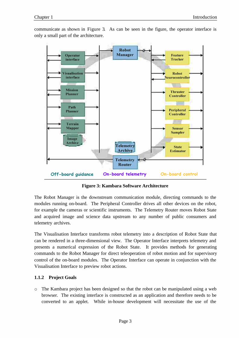
communicate as shown in Figure 3. As can be seen in the figure, the operator interface isonly a small part of the architecture.
Figure 3: Kambara Software Architecture
The Robot Manager is the downstream communication module, directing commands to themodules running on-board. The Peripheral Controller drives all other devices on the robot,for example the cameras or scientific instruments. The Telemetry Router moves Robot Stateand acquired image and science data upstream to any number of public consumers andtelemetry archives.
The Visualisation Interface transforms robot telemetry into a description of Robot State thatcan be rendered in a three-dimensional view. The Operator Interface interprets telemetry andpresents a numerical expression of the Robot State. It provides methods for generatingcommands to the Robot Manager for direct teleoperation of robot motion and for supervisorycontrol of the on-board modules. The Operator Interface can operate in conjunction with theVisualisation Interface to preview robot actions.
1.1.2 Project Goals
o The Kambara project has been designed so that the robot can be manipulated using a webbrowser. The existing interface is constructed as an application and therefore needs to beconverted to an applet. While in-house development will necessitate the use of the

Chapter 1 Introduction
Page 4
application, the essential long-term objective for the operator interface is to be able to useit over the Internet.
o A feature of the operator interface is the use of a Wavefront 3D model for representing thecurrent vehicle state (from the state information received). However, the model issimplistic, as it represents just the frame of the robot. Investigations need to be conductedwith regard to using VRML models that will better represent the state of the robot (withthrusters and cameras).
o A feature of AUVs and an aim of the operator interface is direct teleoperation of robotmotion. To this end, the development of a software joystick needs to be considered inorder to facilitate the operator to manipulate the robot in any or a combination of its fivedegrees of freedom.
o One of the major shortcomings of the GUI layout at the end of 1999 was that it was not asflexible as desired. Automatic resizing was not a feature with most of the componentsrequiring fixed dimensions to obtain the desired layout. Therefore, making improvementsto the GUI involves a redesign of the layout. This also aids the goals stated above,especially the development of a software joystick for aiding direct teleoperation.
o Currently, the interface receives state information from a robot simulator. However, theoverall objective of the Kambara project is for the robot to send state information to theinterface while navigating areas such as the Great Barrier Reef. The robot must alsoaccept commands to enable the operator to map a route for it. To those ends, the existingnetwork design needs to be changed to allow:
- Kambara's on-board system can receive commands from the operator interface and acton it.
- The operator interface can receive the updated telemetry information from Kambaraand display it.
o Enhancement of control modes is considered to ensure only one client can control therobot at a particular time.
1.2 Thesis Outline
The goals of the project necessitate examining of the GUI followed by the software joystickand the network architecture.
Chapter 2 provides a background about the existing GUI layout and follows on to describe theredesign of the GUI layout. The conversion of the existing application to an applet followsthe redesign with the investigation of the use of VRML 3D models concluding the chapter.
Chapter 3 details the process of the software development of a software joystick to be used byoperators to manipulate the direction of the robot. The software joystick is to be developed aspart of the improvements designated for the GUI layout.

Chapter 1 Introduction
Page 5
In Chapter 4, the network architecture of the interface is discussed with particular emphasison the changes required to conform to the long-term goal of the Operator Interface aspect ofthe Kambara project.
Chapters 2,3 and 4 discuss the analysis and design of the applet, the GUI layout, the softwarejoystick and the network architecture. Chapter 5 discusses the implementation of the above,followed by Chapter 6, which describes the testing procedures developed and used during theproject.
Conclusions from this project are drawn in Chapter 7 including a summary of this thesis, mycontribution in terms of the work done and a discussion of the work that could continue usingthis project as a basis.

Page 6
CCHHAAPPTTEERR 22:: GGUUII AANNAALLYYSSIISS AANNDD DDEESSIIGGNN
The existing operator interface is constructed as a Java application. Since the aim of theKambara project is to enable the clients to view state information and send commands to therobot using a web browser, the current application should be converted to a Java applet thatcan subsequently be viewed on a web browser.
The 3D model is an important aspect of the interface. The current application makes use of asimplistic Wavefront model, which just depicts the frame of Kambara. While this is adequatefor viewing the state of Kambara, it can be improved upon by using more complicatedmodels.
As mentioned in Section 1.1.2, the GUI needs to be redesigned to better represent the stateinformation of the robot. Improvements also need to be made with regard to navigation orteleoperation of the robot.
This chapter provides a background of the original GUI software architecture. It follows upwith a description of the improvements made and the subsequent redesign of the GUI. Adiscussion is then presented on issues relating to the conversion of the existing application toan applet. The chapter concludes by outlining the investigation of the usage of a VRML3Dmodel in place of the current model.
The chapter is organised as follows:
• Section 2.1 provides a background of the existing software architecture of the GUI. Thisis important because provides a basis for the remaining sections of the chapter.
• Section 2.2 describes the improvements made to the GUI layout including changes to thesoftware architecture.
• Section 2.3 describes the reasons for converting the application to an applet and the designincluding the software architecture.
• Section 2.4 outlines the investigation conducted to replace the Wavefront 3D Kambaramodel with a VRML model.
• Section 2.5 provides a summary of the chapter detailing the major results of this chapter.
2.1 Background
The Java programming language used for the software development of the operator interface[1]. Java was chosen because:
• It is portable and has cross-platform capabilities.• It has convenient APIs for networking and 3D programming.• It is easy to use for GUI development.
The interface has predominantly been developed using Java2 and Java3D API1.1. Java2contains Swing libraries, which are used for GUI development in this project.

Chapter 2 GUI Analysis and Design
Page 7
The software architecture of the original GUI is shown in Figure 4. MainKambaraClient isthe main module and just an object in which three subcomponents; KambaraClient,KambaraMainFrame and OutputKambaraData are created. KambaraData represents thestate information being received from the robot.
Figure 4: Original GUI Software Architecture
KambaraClient deals primarily with the network details of the client. It is responsible forestablishing a connection between the client and a Java web server via Remote MethodInvocation (RMI)2 [1], and for setting up communication between the client and the server. Italso has a thread object that continually receives state information from the server.
OutputKambaraData is a thread object that runs when a network connection is established.This is responsible for continually updating the GUI components with any new stateinformation received. It is started when KambaraClient receives state information packetsfrom the server.
KambaraMainFrame holds the panel containing all the GUI components; KambaraMain.KambaraMain is a panel that has been divided into a tabbedPane, a 3D model, a video feedplaceholder, a menubar and a message area. Within the tabbedPane, information was dividedinto separate panels, based on the type of information being displayed. These include a
2 RMI and the networking aspects of the Operator Interface are discussed further in Chapter 4

Chapter 2 GUI Analysis and Design
Page 8
TelemetryPanel, CameraPanel, PositionPanel, RawData Panel, DerivedData Panel,MessagesPanel and NavigationPanel.
The TelemetryPanel provides the user with the general information about the vehicle. ThePositionPanel provides a two-dimensional view of the position of Kambara and the relativeposition of the target.
The CameraPanel shows the current pan, tilt and zoom values of the camera on-boardKambara. It is also supposed to be used in case the operator wants to change the pan, tilt orzoom of the camera. This aspect is further discussed in Chapter 4 (Section 4.2.1).
The RawData and DerivedData panels show the sensor data and data computed on-boardKambara, respectively. These panels along with the TelemetryPanel provide all the numericaldata to the client.
The MessagesPanel lists all the warning and error messages that are transmitted to the clientwhile the NavigationPanel is used for manipulating the robot in any or a combination of itsfive degrees of freedom.
The 3D model and the video feed placeholder are in constant view of the client. The videofeed had not been implemented due to the Kambara software development not having reachedthe desired stage. The 3D model is a Wavefront model and depicts the current rotational andtranslation state of the AUV.
After providing the background for the existing software architecture of the GUI, it is nowworthwhile to discuss the improvements that were made, resulting in the redesign of the GUI.
2.2 GUI Layout
The interface depicts most of the state information received from the robot. However,improvements need to be made for viewing the 3D model, the use of the CameraPanel thatcan manipulate the pan, tilt and zoom of the camera on-board Kambara and also in theNavigationPanel, which is used for manipulating the robot itself.
2.2.1 Design Principles
The interface had been designed based on the design principles of space, proximity, alignmentand contrast [8]. These are related to the way in which users perceive information. The sameprinciples were used while redesigning the layout of the interface.
• Space
Space is the most effective element that can be used to provide support for your audiencein their cognitive processing of visual displays. Spatial relationships are perceivedprecognitively - that is, without conscious effort. They do not have to be decoded andinterpreted, as do colour cues, typographical cues, and so on.

Chapter 2 GUI Analysis and Design
Page 9
• Proximity
Elements that are close together in a visual display will be assumed to be related.Elements that are far apart will not be seen as related to each other. When elements are notclearly differentiated by proximity, the user has to group them consciously by focusing onthem, taking in their meaning, and deciding which ones go together.
• Alignment
Humans perceive items that are aligned vertically and/or horizontally to be moreorganised than those that are not, and people process, learn and remember organisedinformation better than unorganised information.
• Contrast
Use contrast to make elements more or less dominant in the display, influencing the orderin which they are processed and their perceived importance or urgency. The primaryforms of contrast are size, colour and shape.
2.2.2 Software Architecture
The architecture was changed to implement and incorporate the improvements designated forthe GUI layout. The changes are highlighted in Figure 5, which illustrates the currentsoftware architecture of the GUI.
A new subcomponent, ThreeDFrame is created in MainKambaraClient. This component is aframe that holds the 3D Wavefront model (loaded into the ThreeDPanel) and is separate to themain interface. In the original implementation, the 3D model was viewed inKambaraMainFrame. While the panel incorporates the model, ThreeDPanel is still created inKambaraMain; it is just not shown in KambaraMainFrame.
Also, the CameraPanel component is no longer a part of the tabbedPane. It now occupies theposition of the ThreeDPanel and the video feed placeholder. It is created as a subcomponentof KambaraMain and not that of the tabbedPane.
The DataPanel is now a new subcomponent of the tabbedPane. It incorporates theinformation contained in the RawData panel and DerivedData panel into one panel. Whilethe Raw and Derived Data panels have not been deleted, they have just been made intosubcomponents of the DataPanel. Another improvement was to completely redesign theNavigation panel to facilitate an easier and more intuitive manipulation of the movements ofthe robot.

Chapter 2 GUI Analysis and Design
Page 10
Figure 5: Current GUI Software Architecture
The rest of the architecture is inherited from the original software design. While the abovewas a brief overview of the improvements made, it is now best to understand all the issuesassociated with the decisions that led to these changes.
• Kambara 3D Model
In the original architecture, the 3D model is viewed in a panel in KambaraMainFrame.This panel is small and hard to navigate. This inadequacy caused it to be renderedvirtually useless as the user could not obtain or gather sufficient information from it. Thatis, while the panel could show the state changes when the interface received informationfrom the robot (or the simulation), it was not very user-friendly in terms of manipulatingthe model. This aspect becomes more evident when the model traverses the boundaries ofthe view and the panel needs to be navigated.

Chapter 2 GUI Analysis and Design
Page 11
An option to rectify this problem was to incorporate the ThreeDPanel module into thetabbedPane. But one of the essential requirements of the panel was for it to be in view ofthe user at all times.
Therefore, it was decided that the model should have its own separate frame,ThreeDFrame, which is shown in Figure 6. The panel is still one of the subcomponents ofKambaraMain. This makes it easier to update the 3D model when the interface receivesstate information.
The creation of ThreeDFrame also presented us with more options, especially whendeveloping the software joystick. Apart from viewing the vehicle state obtained from therobot, it can be used to simulate the orientation of the robot for a move command. Thesedetails as well as other aspects of the development of the software joystick are furtherdiscussed in Chapter 3.
Figure 6: ThreeDFrame
• Camera Panel
The Kambara model and the video feed placeholder were supposed to be constantlyvisible to the user. It was planned that the digitiser would be used to continually refreshan image, which would be presented in the GUI. Unfortunately, the AUV developmenthas not reached the stage where a video stream could be obtained and this feature could betested.

Chapter 2 GUI Analysis and Design
Page 12
It is also useful to have the camera in constant view as this gives the operator anopportunity to know the state of the camera at all times and therefore adequately knowwhich direction the camera is pointing to.
The panel also has utilities for sending camera commands to the robot that would helpmap a route for Kambara. This will help the operator change the pan, tilt or zoomanytime, based on the state of the robot. This also provides an opportunity to plan ahead,avoid obstacles and map a route for the robot.
Therefore, the video feed placeholder was removed and replaced with a visualisation ofthe pan, tilt and zoom values of the camera (see Figure 7).
Figure 7: Camera Panel
• Data Panel
As mentioned before, the RawData panel contains data that is obtained directly from thesensors. On the other hand, the DerivedData panel contains information that is computedon-board Kambara. The Data panel incorporates both these forms of data onto one panelas shown in Figure 8. This gives users an opportunity to compare similar sets of valuesand thereby ascertain the effect of factors such as gravity.
The raw data depicted in the panel includes:
1. Motor torque, current and voltage values for each of the five thrusters.

Chapter 2 GUI Analysis and Design
Page 13
2. Compass values including the roll, pitch and yaw, magnetic disturbances, temperatureand field distortion.
3. Velocity and accelerometer values.
Figure 8: Data Panel (combines Raw and Derived Data)
The derived data is the data computed on-board Kambara. The data depicted includes:
1. Accelerometer values.2. Current vehicle position and estimated target position.3. Current quaternion value of the vehicle computed using the compass roll, pitch and
yaw values (raw data).
This along with the Telemetry panel provides a general picture of the information beingreceived from Kambara and makes it much easier to analyse.
• Navigation Panel
The implementation for navigating the robot in its five degrees of freedom was minimalistand laborious for the operator. All those components were deleted and the need forimprovements led to the investigation, design and development of a software joystick.The joystick allows the operator to use mouse clicks and / or keyboard events to changethe direction of the robot.
With a picture of the current GUI software architecture in mind (for an application), thedetails of the conversion of the existing application to an applet can be explained.

Chapter 2 GUI Analysis and Design
Page 14
2.3 Applet
To allow multiple clients to connect to the robot and view the state information, a web-basedoperator interface is required. Of these clients only one will be able to control Kambara.
Hence, the application is converted to an applet while allowing the interface to also be viewedas an application. The main reason for this was the ease of use associated with applicationsfor in-house development, especially for testing purposes.
2.3.1 Software Architecture
The main factor associated with the design was to be able to start the interface from theapplet. That is, the applet would serve as a starting point or as a link to the interface. Thesoftware architecture was developed and modified accordingly.
The software architecture of the applet is given in Figure 9. KambaraMainApplet is the mainmodule that holds the applet and has four subcomponents; KambaraMainFrame,KambaraClient, OutputKambaraData and ThreeDFrame. Essentially, KambaraMainApplettakes the role of MainKambaraClient in the application.
Figure 9: Kambara Applet Software Architecture
KambaraClient handles all the network details of the client while OutputKambaraDataupdates the state information on the interface. KambaraMain is the panel that holds all theGUI components and is a subcomponent of KambaraMainFrame3.
3 Section 2.1 provides more details about KambaraClient, KambaraMainFrame, KambaraMain andOutputKambaraData

Chapter 2 GUI Analysis and Design
Page 15
The only difference between the architectures of the application (shown in Figure 5) and theapplet (Figure 9) is that KambaraMainApplet assumes the role of MainKambaraClient. Thisfacilitates the development of the interface as an application as well as an applet.
The next stage in the development of the GUI is the investigation of a VRML 3D model forthe interface.
2.4 VRML Model of Kambara
The Wavefront model used in the interface was developed from a VRML model. Due toconversion problems, the model is very simplistic and consisted of just the frame of the robot[see Figure 10].
The model is visualised using the Java3D API [10][14]. Pictures rendered with Java3D arecalled scenes (or “virtual universe”) that are in turn broken into subcomponents, namelybehaviour, model, object characteristics, 3D co-ordinate, math. These create a complex worldof 3D objects and are a major cause in the decrease in the speed and performance of theinterface.
It was felt that having a more complicated model including thrusters and cameras wouldgreatly enhance the operator’s understanding of the robots’ behaviour. This would be bestachieved by directly loading a VRML model and not converting it into any other format.
Figure 10: Kambara Wavefront Model
A VRML model depicting the cameras and the thrusters along with the frame of Kambara[see Figure 11] had been developed at the Systems Engineering Department in RSISE. But,one of the major considerations to be taken into account was again the performance and thespeed with which the client would update its GUI. That is, use of the VRML model shouldnot come at the expense of further reduction in performance.
It was found that the Java3D API in it current form, does not support the loading of VRMLmodels into a scene. To this end, the Internet was scanned for any software packages(preferably developed in Java) that would help us achieve the objective. This led us to theNCSA Portfolio [12, Appendix A]. This utility is used in conjunction with the Java3D API toload models of different formats including Wavefront and VRML.

Chapter 2 GUI Analysis and Design
Page 16
Figure 11: VRML Model
But, NCSA Portfolio could not be used to load VRML models due to problems encounteredwith the VRML model and the utility itself. These are discussed in the following section.
2.4.1 Loading Problems
The problems encountered with the VRML model and NCSA Portfolio were serious enoughfor me to stop the investigation and continue using the Wavefront model. They were:
• NCSA Portfolio supports the loading of only VRML97 models.• The loader in NCSA Portfolio, used to load the models does not possess any parameters to
properly position the model in the ThreeDFrame. We could also not use the Java3D APImethods, as they do not support VRML models.
• The simplest VRML model available [Figure 11] was 1 Megabytes in size. Loading a fileof such size led to a drastic reduction in the performance, which was unacceptable. Asmentioned in the previous section, use of the model could not come at the expense ofspeed or performance.
Therefore, it was decided that the existing Wavefront model would continue to be used tilltechnologies improved and facilitated easier and faster use of the VRML model.
2.5 Chapter Summary
The redesign of the GUI included creation of a separate frame for just the 3D model,incorporation of the raw sensor data and the derived data into one panel and the separation ofthe CameraPanel from the tabbedPane that was made a part of the main interface. The appletarchitecture is very similar to the application thereby facilitating the execution of the interfaceas an application as well as an applet. Currently, he VRML 3D model cannot be used in placeof the Wavefront model due to constraints imposed by Java3D and NCSA Portfolio.
It was mentioned earlier in the chapter that the NavigationPanel was completely redesignedwith all the existing components deleted and a software joystick developed in place. The nextchapter discusses the software joystick in detail including the analysis and the design.

Page 17
CCHHAAPPTTEERR 33:: SSOOFFTTWWAARREE JJOOYYSSTTIICCKK
Chapter 2 was concerned with the redesign of the operator interface GUI. This included theredesign of the NavigationPanel. This chapter details the reasons for the changes in theNavigationPanel and the development of a software joystick to be incorporated as part of thenavigation mechanism of the interface. The software joystick is to be used by the operator tobe able to manipulate the robot in any or a combination of its five degrees of freedom.
However, as the mechanisms for actually moving the robot have not yet been developed, thischapter will concentrate on the requirements and the associated design involving the joystick.It will first provide a background about why the interface needs a software joystick followedby detailed explanations about what functions the joystick needs to perform and the designused to implement those functions.
This chapter is organised as follows:
• Section 3.1 describes the control modes that were set in place for the operator interface in1999 [1]. These help determine why the software joystick needs to be developed.
• Section 3.2 outlines the requirements of the joystick including the constraints.• Section 3.3 discusses the design including a detailed explanation of the software
architecture of the joystick.• Section 3.4 explains the major outcomes of this chapter as a summary.
3.1 Control Modes
Four control modes for the operator interface have been defined. These would facilitatemultiple users to view the state information being sent from the robot, even if only one ofthem is in control of it. The four control modes are Observer, Individual control,Teleoperation and Supervisory control.
3.1.1 Observer Mode
Users that do not control the robot are in Observer mode. It enables them to watch theactivities of the operator and view all state information sent by Kambara. This is the state inwhich users should be in, if they have not successfully gained control of the robot.
3.1.2 Individual Control Mode
This mode is used when it is necessary to fire individual thrusters. This mode would comeinto use when say; Kambara is in an awkward position next to a rock. It would also be usefulif the operator wants to manipulate the camera (pan, tilt and zoom).

Chapter 3 Software Joystick
Page 18
3.1.3 Teleoperation Mode
This mode is used to enable the operator to move Kambara in any or a combination of its fivedegrees of freedom. All of the thrusters will be co-ordinated to carry the specified motionout.
3.1.4 Supervisory Control Mode
This control mode is similar to that used on the rover that landed on Mars in 1998 [13]. Itessentially allows the operator to plan a route.
The joystick is meant to be a stepping-stone in implementing the Teleoperation control modeand as a major improvement to the previous navigation utilities provided in the interface.
3.2 Requirements and Analysis
The implementation for the teleoperation mode in the existing application was basic and non-intuitive. The user had to laboriously select one of ten directions and separately manipulatingthe roll, pitch and yaw as shown in Figure 12.
Figure 12: Robot Navigation Controls (1999)
To make navigating the robot easier, the concept of a software joystick was investigated. Thebasic idea is to allow:
• Mouse clicks and / or keyboard events to determine the surge, heave, roll, pitch and yawin a non-laborious manner.
• Not slow down the interface any more than its current state.• Be able to type specific values of the above-specified degrees of freedom and change
them.• Be able to abort the prospective change if the operator is unsatisfied with the changes.

Chapter 3 Software Joystick
Page 19
• Have a view of the changes in the orientation of Kambara. This would be done using theexisting 3D model.
3.3 Design
3.3.1 Considerations
It is human nature to get frustrated when updates of information are slow and the interface isnot easy to use. The 3D model of Kambara uses the Java3D API that results in a substantialdecrease of speed and decrease in the performance. It was necessary that the joystick did notslow the interface any further. Having another 3D view would necessitate a similar use ofJava3D, which would make the interface unusable due to its poor performance.
As mentioned before, the ease of use for the operator is another major consideration. Thejoystick will not be useful if the operator is unable to grasp its intricacies in a short span oftime. It was for these above-mentioned reasons that two two-dimensional views were used tomanipulate the robot. They help keep the different components of the joystick, simple andeasy to use. Having taken into account the factors used in determining the design, the softwarearchitecture of the joystick can now be described.
3.3.2 Software Architecture
The main module that contains the joystick is NavigationPanel, which in turn is asubcomponent of the tabbedPane 4. It is just a panel that holds 3 subcomponents; TopPanel,SidePanel and MovementsPanel. The architecture is shown in Figure 13.
Figure 13: NavigationPanel Software Architecture
4 See Chapter 2, Section 2.2 for more details about the current software architecture of the GUI

Chapter 3 Software Joystick
Page 20
• TopPanel
The TopPanel lets the operator manipulate three of the five possible degrees of freedom.This is accomplished through the use of mouse clicks. The panel provides the operatorwith a perspective of the top view of the robot, which is shown in Figure 14. The changesin some selective movements can be generated based on this view.
The view allows the operator to set the surge, yaw and roll of the robot. That is, thetranslation in the X direction (surge) and the rotations in the X and Z directions (roll andyaw respectively) are set using this panel. These can be set intuitively through mouseclicks and / or a combination of the keyboard and mouse.
Figure 14: Top View of Kambara
The 3D model is used concurrently with the panel to provide a simulation of the change inthe orientation of the robot. This change will occur on the completion of the desiredsurge, yaw or roll. This gives the operator a better idea of the robot’s movements. It alsoacts as a feedback so that the operators can correct the values and be able to map a routefor the robot. An example of the use of the 3D model to view the change in theorientation through the use of the TopPanel is given below in Figure 15.
Figure 15: Simulation of the movements of the joystick (in the 3D model)

Chapter 3 Software Joystick
Page 21
• SidePanel
The Side view of the robot is depicted in this panel. This is illustrated in Figure 16. Thepitch and heave movements5 are set using this component of the joystick. These arechanged or set through the use of mouse clicks.
Figure 16: Side View of Kambara
The usage of the 3D model is the same as in the TopPanel with the types (directions) ofmovement being different.
• MovementsPanel
Another method of changing any degree of freedom is through the MovementsPanel.There are textfields that accept key entries and implement the specified changes in theorientation. The changes are the same, as one would expect from the TopPanel or theSidePanel.
But the textfields are also used to show the latest changes implemented through the use ofthe TopPanel or the SidePanel [see Figure 17].
Figure 17: Current Translations and Rotations
The Send the Abort buttons shown in Figure 17 are present to facilitate the sending andaborting of move commands to the robot, taking the required changes as parameters.
5 Pitch is the rotation in the Y direction while heave is the translation in the Z direction

Chapter 3 Software Joystick
Page 22
3.4 Chapter Summary
A software joystick has been analysed and designed for facilitating direct teleoperation of therobot. It consists of two two-dimensional views (top view and side view) and manipulates thedesignated five degrees of freedom through keyboard and / or mouse inputs. There is a panelfor manual numerical changes as well (MovementsPanel).
The 3D model is used to simulate the prospective changes in the translations and the rotations.Due to the overall Kambara software development not having reached a stage where the robotaccepts move commands, the joystick does not send or abort any commands.
In the event that the joystick is used to send the commands, we need to further ourunderstanding of the networking aspects of the operator interface. The next chapter discussesthese aspects and provides explanations about how the clients can send commands to therobot.

Page 23
CCHHAAPPTTEERR 44:: NNEETTWWOORRKK AANNAALLYYSSIISS AANNDD DDEESSIIGGNN
The previous chapter discussed one of the first stages of teleoperation, that is, thedevelopment of a software joystick. The next stage essentially involves the transmission ofcommands to it and for Kambara to act on those commands. This involves a detaileddiscussion of the network architecture of the operator interface.
This chapter starts off by describing the architecture that was in place at the end of 1999. Thechapter goes on to discuss the requirements and analysis for sending commands to the robotand receiving Telemetry data from it. It then concludes with a discussion of the long-termgoal for the interface network design and the conformance to the long-term goal.
The rest of the chapter is organised as follows:
• Section 4.1 gives a background of the Network Architecture including the architecture thatwas already in place at the beginning of the project and the functions of the server and theclient side.
• Section 4.2 outlines the requirements and analyses the transmission of camera commandsto the robot and reception of telemetry router data from the robot.
• Section 4.3 describes the long-term goal for the interface network design and the changesused to make the current architecture conform to it.
• Section 4.4 gives a summary of the main outcomes of the network analysis and design.
4.1 Background
The system depicted in Figure 18 was the implementation at the beginning of the project.There are multiple clients (applications) connecting to a Web server that is written in Java.
4.1.1 Server
The essential role of the server is to receive state information from the robot and distribute itto the clients and issue commands to the robot from 'one' of its clients. Clients register withthe server via an RMI connection and thereby request state information. All the clientsregistered with the server then receive UDP 6 packets containing the latest state information.
RMI allows an application to call methods and access variables inside another application,which may be running in a different Java environment or a different system altogether, and topass objects back and forth over a network connection. The primary goal of RMI was tomake interacting with a remote object as easy as interacting with a local one.
In addition, however, RMI includes more sophisticated mechanisms for calling methods onremote objects to pass objects or parts of objects either by reference or by value, as well as
6 See Appendix B for more details about User Datagram Protocol (UDP)

Chapter 4 Network Analysis and Design
Page 24
additional exceptions for handling network errors that may occur while a remote operation isoccurring.
Figure 18: Original Network Design
The server is also responsible for ensuring that only one client at a time has the ability tocontrol the vehicle, via the ControlState object stored on the server. Therefore the client canissue commands at any time even while the server is receiving and distributing the stateinformation packets.
4.1.2 Client
The basic role of the client is to register with the server and receive the latest state informationof the robot, from it. The client is currently an application that can be executed on anymachine supporting the Java runtime environment. In the event that the client is also incontrol of the robot the ability to issue commands such as changing the pan, tilt or zoom ofthe camera on-board Kambara and moving the robot in any or a combination of its fivedegrees of freedom, is provided.
To receive state information from the server, the client uses the RMI connection to access theserver's method addStateInfoListener, which stores the client's address and port number. Theinformation received by the client is in the form of UDP packets, which are unreliable and can

Chapter 4 Network Analysis and Design
Page 25
get lost. But this disadvantage is compensated by the fact that the Kambara system iscontinually sending information. Also, UDP is very fast and does not require a confirmationof each packet.
As mentioned in the previous subsection, the methods for issuing commands are defined inthe server's object ControlState. But, while this ability is provided to the client, thefunctionality for sending commands has not been provided. This needs to be addressedbecause ultimately, the manipulation of the robot is going to be achieved only via the operatorinterface.
Another issue to be addressed is that the client receives state information from a simulator andnot the actual robot. For the operator interface to be operational, this aspect needs to becorrected as the aim of the interface is to present data that is either produced on-boardKambara or from its components.
Having described the roles of the server and the client, it is now useful to analyse the changesthat need to be made in order for the operator interface to properly interact with the robot.
4.2 Requirements and Analysis
4.2.1 Camera Commands
While the joystick commands can be simulated using the 3D model as discussed in Chapter 3(Section 3.3), the overall aim is to be able to communicate with the system on-board the robotand send the joystick commands to it.
The definition and sending of camera commands is the first part in that process. Based on thesoftware development on-board Kambara, a vector of camera command data was defined.This is listed in Table 1 where the pan, tilt and zoom values are absolute values.
Range (Bytes) Data Type Data Represented
0-7 Long Initialise (boolean; always = 1)
8-15 Double Pan Value
16-23 Long Absolute Pan (boolean)
24-31 Double Tilt Value
32-39 Long Absolute Tilt (boolean)
40-47 Double Zoom Value
48-55 Long Absolute Zoom (boolean)
Table 1: Vector of Camera Command Data

Chapter 4 Network Analysis and Design
Page 26
The telemetry data received by the client from the robot (via the server) contains the updatedpan, tilt and zoom values of the camera. Therefore, the requirement is to send the commandsquickly through UDP packets, with the client using the updated values to determine if thecommand was received properly or lost. Considering that the client receives simulator data, ameans to get data from the Telemetry Router on-board the AUV needs to be analysed.
4.2.2 Telemetry Router
If the clients are to receive proper telemetry data and actually determine the status ofKambara, the server needs to communicate with the Telemetry Router in real time instead of asimulator [Appendix C]. A vector of the data received from the Telemetry Router is given inTable 2.
Some of the variables such as computer status and target velocity are not represented in GUI.These have no bearing currently, with their values constantly set to zero. It was determinedthat corresponding changes to the GUI would be made when the Kambara softwaredevelopment reached a stage where it defined such variables.
Also, considering that Kambara will continuously send telemetry data, speed will be a biggerconsideration than reliability. Therefore, it was decided to continue using the UDP protocol(in a similar manner to receiving simulator data)
Range of data in doubles Data Represented
0-2 Robot position x, y, z values
3-6 Robot position – Quaternion
7-9 Kambara velocity u, v, w values
10-12 Kambara angular velocity p, q, r values
14-16 Target position x, y, z values
17-20 Target position – Quaternion
21-23 Target velocity u, v, w values
24-26 Target angular velocity p, q, r values
28-32 Motor torque (5 thrusters)
34-38 Motor voltages
39-43 Motor currents
45 Camera Pan value
46 Camera Tilt value
47 Camera Zoom value
48 Computer Status (64 bits of unsigned chars)
Table 2: Vector of Telemetry Router Data received from Kambara

Chapter 4 Network Analysis and Design
Page 27
The essential goal of implementation of the camera commands and telemetry router data is forthe Network Design to conform to the long-term goal that has already been defined. Thedesign issues relating to the implementation of sending camera commands and receivingtelemetry data are discussed next.
4.3 Design
4.3.1 Long Term Goal for Network Design
The long-term goal for the Interface Network Design [1] is depicted in Figure 19. As isevident from the figure, the design shown in Figure 18 bears a few differences to it. Theessential idea was to interface the client with the server and have that in turn communicatewith the AUV.
Figure 19: Long-Term Goal for Network Design
The Web server in the figure is used for initialisation of the applet. From that point onthough, all client-server communication will be between the client applet and the Java servervia RMI. A simple socket connection will be used between the Java server and the computeron-board the AUV, since RMI is only used between two Java objects.

Chapter 4 Network Analysis and Design
Page 28
4.3.2 Conformance to Long-term Goal
The major differences between the original design and the long-term goal (Figures 18 and 19)are given below. The long-term view for the interface network design included the executionof the client as an applet and proper communication with the robot. This would be in the formof commands from the client to the robot and state data from the robot to the client. Theconformance criteria are
1. The clients are constructed as applets as opposed to applications.2. The server gets state information from the Telemetry Router on-board Kambara as
opposed to a simulator.3. Mechanisms need to be constructed for a client to send commands to the robot. While
there are methods defined for sending commands, these have not been implemented.
As mentioned in Section 2.3, the client application has been converted to be used as an appletas well. This achieves the first of the three goals stated above. The network architecture hadto be changed so as to allow proper communication between the client and the robot. Thecurrent network design is shown in Figure 20. Currently, the software used to run the cameraon-board Kambara does not accept socket connections. It only listens for UDP packets.
Figure 20: Current Interface Network Design

Chapter 4 Network Analysis and Design
Page 29
The KambaraServer takes the robot machine address and the camera port number asparameters and uses them to create UDP socket connections to the robot. The client uses theControlState object on the server to send camera commands and the server listens fortelemetry router data, which is then passed on to all the clients. The camera values arecontained in the telemetry data (Table 2) and therefore it can be determined if the cameracommand was transmitted and implemented.
A typical flow of commands throughout this system is as follows.
1. A client sends a registration command through a RMI connection, indicating that theywish to receive state information
2. The server registers the client taking the address and port number and puts thatinformation onto a vector of clients.
3. Each telemetry router data packet received by the server is sent to all the clients. Thepackets are continuously received by the server and are sent to the clients without anydecoding.
4. The client receives the telemetry data, decodes the UDP packets and updates the GUIbased on the data.
5. The client then requests control of the vehicle.6. The server sends an error message back to the client if another client is already in control
of the AUV. In the event that no one is controlling the vehicle, the client is given controland GUI is updated to reflect the adequate mode.
7. On obtaining control of the vehicle, the client can send commands to manipulate thecamera on-board Kambara. The state information packets reflect the changes, which areupdated on the GUI.
8. The client can relinquish control of the vehicle and go back to the Observer mode at anytime.
4.4 Chapter Summary
The original network design had shortcomings with respect to sending proper commands tothe robot and receiving actual telemetry data from the robot. The long-term goal for theinterface network design was defined in 1999 [1]. The Network design was changed toimprove the deficiencies in the original design and conform to the long-term goal.
The previous chapters (Chapters 2 and 3) along with this chapter, discussed the analysis anddesign aspects of the project. We should now discuss the implementation of the stateddesigns. This is discussed further in the next chapter titled "Implementation".

Page 30
CCHHAAPPTTEERR 55:: IIMMPPLLEEMMEENNTTAATTIIOONN
This chapter discusses one of the most important aspects of the project. The software goalsoutlined in Chapter 1 have been analysed and adequately designed as described in Chapters 2,3 and 4. But these need to be implemented for the successful completion of the project. Thesoftware objectives achieved and discussed in this chapter include,
1 Conversion of the application to an applet.2 Improvements and redesign of the GUI layout.3 Development of a software joystick to aid in the manipulation of the surge, roll, pitch,
yaw and heave movements of the robot.4 Sending commands to the robot, in this case, camera commands.5 Receiving telemetry router data continuously from Kambara.
The rest of the chapter is organised as follows,
• Section 5.1 outlines the improvements made to the GUI layout and describes the newstructure.
• Section 5.2 discusses the implementation of the applet and the problems associated with it.• Section 5.3 details the issues associated with the implementation of the software joystick.• Section 5.4 describes the implementation of the network improvements that will be a
stepping stone to conforming to the long-term goal of the Interface Network Design.• Section 5.5 summarises the chapter concentrating on the outcomes of the implementation
stage.
5.1 GUI Layout
As discussed in Section 2.3.2, the software architecture of the GUI was improved upon. Thisresulted in the state information being displayed as follows:
1) TelemetryPanel: relating to the general information about the vehicle.2) PositionPanel: a two-dimensional indication of the position of the vehicle and the
comparative position of the target.3) DataPanel: depicts two sets of values; the numerical values coming directly (raw) from
the sensors on the vehicle and the numerical values that have been derived on-board thevehicle.
4) MessagesPanel: any error, status or warning messages that are transmitted to the client.5) NavigationPanel: controls used to navigate the robot when in teleoperation mode.
Currently, this is implemented using a software joystick.6) ThreeDFrame: A separate frame holding the 3D model of Kambara and depicting its
current rotation and translation state.7) CameraPanel: shows and manipulates the current pan, tilt and zoom values of the camera.
The first five panels were constructed using a tabbedPane and implemented using GUIcomponents developed using source code found on the Internet or developed originally. As

Chapter 5 Implementation
Page 31
mentioned in Section 2.3.2, the CameraPanel is in constant view in the current interface. Thesnapshots of the panels are provided in Appendix E.
The only problem encountered with the GUI was the instability of the ThreeDFrame,especially on Solaris machines. This was predominantly due to Java3D, which is still in itsinfancy in terms of development. It is believed that future versions of Java3D would be muchmore stable and should solve the problem. But in case this problem still persists, there shouldbe a reassessment of the use of the 3D model.
5.2 Applet
The Java applet used to load the operator interface is given in Figure 21. The applet containsa brief description of the Kambara project and has four buttons that have varying purposes.
Figure 21: Kambara Applet
1) Start Client is used to start an instance of the interface.2) 3D Panel starts the ThreeDFrame holding the Wavefront model (Figure 10). It is
activated when the user starts the client.3) Quit Client will be used when the client wants to end the session. It hides the interface
and the client can then quit the applet.4) Kambara shows the user an image of the robot (Figure 2).
But there were problems associated with loading the applet into a web browser such asNetscape. The problems are discussed in the following Sections 5.1.1 and 5.1.2.
5.1.1 Java Plug-In for Web Browsers
Current web browsers do not support Swing libraries used in Java 2 [9], the version of Javaused in the development of the interface. Java Plug-Ins [11] need to be installed and run with

Chapter 5 Implementation
Page 32
the present versions of Internet browsers, notably Netscape. This is in order for them to notonly display Java3D objects, but also support Swing libraries.
5.1.2 HTML Conversion
Another problem was that the HTML document loading the applet needs to have tags that willspecify the browser to use the Java Plug-In and not its own Java Virtual Machine (JVM). Bydefault, browsers such as Netscape use their own JVM and need to be specifically informed touse the Java Plug-In. Therefore, a Java Plug-In HTML Converter [11] needs to be used toconvert standard HTML pages to a form that specifies the usage of the Java Plug-In.
The above problems added to the slow performance of the applet, especially in loading theinterface. This aspect is further discussed in the next chapter that describes the testingprocedures used during the project.
5.3 Software Joystick
The joystick implementation was quite time consuming with issues needing to be addressed atevery juncture. Therefore, the joystick had to be implemented in a number of steps based onthe issues. These issues are detailed in the following subsections.
5.3.1 Co-ordinate System
Because the joystick was implemented as two 2D panels, TopPanel and SidePanel, issuescorresponding to the Co-ordinate system needed to be addressed. Specifically, we needed toaddress the fact that in 2D, Java only recognises the X and Y-axes. Therefore, depending onthe view being used, we needed to include the Z-axes in place of either the X or the Y-axes.
Another issue was that the view might not necessarily interpret the horizontal direction to bethe X-axes with the vertical direction as the Y-axes. This is evident in Figure 22, whichshows the orientation of Kambara in its three axes and the corresponding interpretationrequired for the Top and Side Views.
Figure 22: Co-ordinate System (Kambara and Joystick Panels)

Chapter 5 Implementation
Page 33
5.3.2 Rotation Angles and Quaternions
The second problem faced during the implementation of the joystick was the computation ofthe angles. These could not be computed in four quadrants, as is normally the case. It had tovary depending on the view. For example, for either of the panels, the yaw, pitch or rollangles will have a range of ± 180°. But while the roll and yaw angles are computed withrespect to the vertical axis in the TopPanel, the pitch is computed with respect to thehorizontal axis in the SidePanel. This is depicted in Figure 23.
Figure 23: Relative movements in the TopPanel and the SidePanel
The other problem concerning the angles was the conversion to Quaternions. Quaternions areused for a singularity-free representation of the attitude of the robot. In the operator interface,the 3D model uses quaternions to represent the orientation of the robot. While Java3D hasmethods and constructors to create quaternions, there are none for creation using three angles(roll, pitch and yaw).
The solution to the problem was to create individual quaternions for the roll, pitch and yawand then multiply them together to compute the overall quaternion for the 3D model. That is,methods were developed that would compute the quaternion given one angle at a time.Therefore for the roll, pitch and yaw, the individual quaternions computed were as follows:
The quaternion was computed using the Quat4D class available in the javax.vecmath libraryin Java3D API 1.1.
For Roll: Quat4d{sine(Roll/2), 0, 0, cosine(Phi/2)}
For Pitch: Quat4d{0, sine(Pitch/2), 0, cosine(Theta/2)}
For Yaw: Quat4d{0, 0, sine(Yaw/2), cosine(Yaw/2)}
These individual quaternions are then multiplied together to get the final quaternion. Java3Dprovides methods for this very purpose.

Chapter 5 Implementation
Page 34
5.3.3 Manipulations using MovementsPanel
The last problem encountered was concerning the manipulations the operator would makeusing the MovementsPanel. The question was whether the MovementsPanel would act as acorrection mechanism for the operations made using the TopPanel and the SidePanel orwhether it would have a similar role to those panels, albeit a much more specific role.
It was decided that the MovementsPanel could perform both roles. For example, if the userwanted to correct a pitch of 45 degrees to 30 degrees, a manual change of –15 degrees couldbe implemented using the MovementsPanel. Alternatively, if the operator wanted to changethe pitch by a further 50 degrees, which usually accomplished using the SidePanel theMovementsPanel could implement that as well. In the end, the ultimate interpretation lieswith the operator.
5.4 Networking
The implementation of the network design was relatively easy. Use of the UDP protocolensured that the confirmation of packets or commands was not necessary. The onlyforeseeable problem lay in the Java Virtual Machine allowing socket connections to listen,connect and accept information. But the policy file (java.policy) that determines what code ispermitted to perform each action already allowed the use of socket on the defined ports.
There were two major problems associated with the network communication with the robot.The first problem was concerning the interpretation of the Telemetry Router data while thesecond problem was about the conversion of the camera values into bytes.
5.4.1 Data Interpretation
The GUI components were developed using the simulator data in mind. The TelemetryRouter data is similar to the simulator with a few minor differences. But currently, the onlymeaningful information that the operator receives in the telemetry router data is the vehiclestate (position and orientation), vehicle velocity and the camera values. Therefore, it wasdetermined that a reassessment of the GUI components will be done once the telemetry datacontains more useful information.
The vehicle state in the telemetry data is determined from a compass installed as part of theKambara hardware. It computes the position and the quaternion that is subsequently viewedon the ThreeDFrame.
5.4.2 Conversion to Bytes
Problems arose when the camera command needed to be created in the form of UDP packets.The problem was with the conversion of the double and long values into bytes. Because apacket is the simplest form of data, all the information contained in it is in the form of bytes.Doubles and longs are 64 and 32-bit floating point datatypes respectively.
Chapter 5 Implementation
Page 35
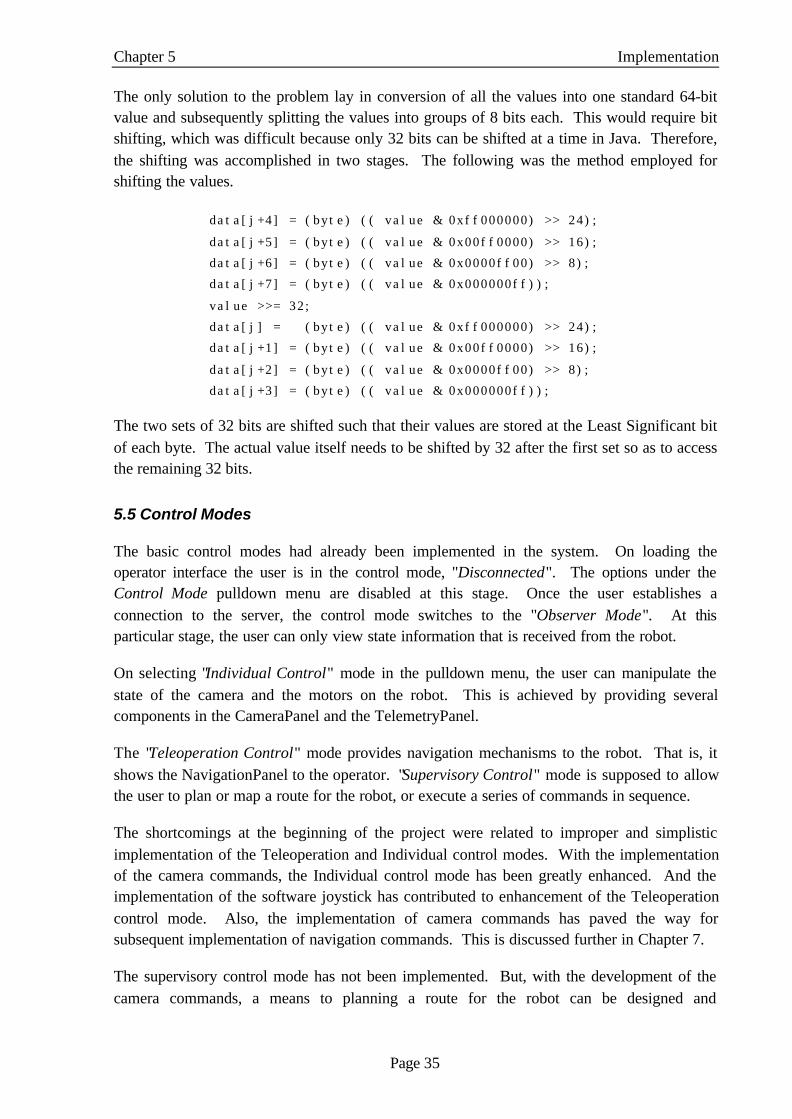
The only solution to the problem lay in conversion of all the values into one standard 64-bitvalue and subsequently splitting the values into groups of 8 bits each. This would require bitshifting, which was difficult because only 32 bits can be shifted at a time in Java. Therefore,the shifting was accomplished in two stages. The following was the method employed forshifting the values.
data[j+4] = (byte) (( value & 0xff000000) >> 24);
data[j+5] = (byte) (( value & 0x00ff0000) >> 16);
data[j+6] = (byte) (( value & 0x0000ff00) >> 8);
data[j+7] = (byte) (( value & 0x000000ff));
value >>= 32;
data[j] = (byte) (( value & 0xff000000) >> 24);
data[j+1] = (byte) (( value & 0x00ff0000) >> 16);
data[j+2] = (byte) (( value & 0x0000ff00) >> 8);
data[j+3] = (byte) (( value & 0x000000ff));
The two sets of 32 bits are shifted such that their values are stored at the Least Significant bitof each byte. The actual value itself needs to be shifted by 32 after the first set so as to accessthe remaining 32 bits.
5.5 Control Modes
The basic control modes had already been implemented in the system. On loading theoperator interface the user is in the control mode, "Disconnected". The options under theControl Mode pulldown menu are disabled at this stage. Once the user establishes aconnection to the server, the control mode switches to the "Observer Mode". At thisparticular stage, the user can only view state information that is received from the robot.
On selecting "Individual Control" mode in the pulldown menu, the user can manipulate thestate of the camera and the motors on the robot. This is achieved by providing severalcomponents in the CameraPanel and the TelemetryPanel.
The "Teleoperation Control" mode provides navigation mechanisms to the robot. That is, itshows the NavigationPanel to the operator. "Supervisory Control" mode is supposed to allowthe user to plan or map a route for the robot, or execute a series of commands in sequence.
The shortcomings at the beginning of the project were related to improper and simplisticimplementation of the Teleoperation and Individual control modes. With the implementationof the camera commands, the Individual control mode has been greatly enhanced. And theimplementation of the software joystick has contributed to enhancement of the Teleoperationcontrol mode. Also, the implementation of camera commands has paved the way forsubsequent implementation of navigation commands. This is discussed further in Chapter 7.
The supervisory control mode has not been implemented. But, with the development of thecamera commands, a means to planning a route for the robot can be designed and

Chapter 5 Implementation
Page 36
implemented. This would require the use of live video, which incidentally is also part of theNavigationPanel. This is also discussed further in Chapter 7.
5.6 Chapter Summary
While the creation of the applet did not pose any problems, the loading of the applet onto aweb browser was a different matter entirely. The problems were associated with Java Plug-Infor Java 2 and HTML conversion relating to the Java Plug-In.
The GUI has been redesigned and along with the menubar and the message area, it nowconsists of five tabbedPanes, a ThreeDFrame for the 3D model and a CameraPanel that is inconstant view of the user. The main problem concerning the GUI was the instability of theThreeDFrame, especially on Solaris machines.
The joystick was successfully implemented with the majority of the problems confined to co-ordinate and angle conversions. The network design developed in Chapter 4 (Section 4.3)was also implemented with camera commands sent to the robot and feedback receivedthrough the telemetry router data.
The control modes were also properly implemented and enhanced. This was partiallyachieved through the development of the software joystick and the enhancement of thenetwork design.
The next step in the process of successfully completing the project is to validate and verify thecorrectness of the implementation with respect to the analysis and the design. The testingprocedures used for this purpose are detailed in the next chapter.

Page 37
CCHHAAPPTTEERR 66:: VVAALLIIDDAATTIIOONN AANNDD VVEERRIIFF IICCAATTIIOONN
The implementation needs to be validated and verified so as to determine if it conforms to theanalysis and the design. This chapter discusses the testing of the implementation, therebydetermining whether it satisfies the objectives of the project as stated in Section 1.1.2. Thischapter is organised as follows,
• Section 6.1 describes the testing procedures that were central to the implementation.• Section 6.2 details the testing of changes implemented in the GUI• Section 6.3 outlines the testing issues related to the implementation of the applet.• Section 6.4 discusses the testing of the joystick and the validation issues related to it.• Section 6.5 details the testing concerning communication with the robot.• Section 6.6 explains the testing conducted for determining if control modes have been
correctly implemented.• Section 6.7 summarises the chapter concentrating on the outcomes of the testing process.
6.1 Testing Procedures
The operator interface was predominantly tested on a Solaris machine. This is because theWindows operating system poses constraints on the location of the client and the server. Thatis, on a Windows machine, both the client and the server needed to be run on the local host,and this leads to a poorer performance.
Another reason for the preference of Solaris was because the server had to be executed onhughes.anu.edu.au, which could not be achieved with a client running on Windows. Thereason being that Kambara would only accept or listen for camera commands from thatparticular machine. While this scenario is not ideal, it had to suffice for testing purposes,especially concerning camera commands and the client receiving telemetry data.
Also, the camera was predominantly plugged onto nozomi.anu.edu.au and tested there. Thiswas not ideal, as one could only observe the status at the beginning and the end and therebydetermine the changes in the pan, tilt and zoom.
6.2 GUI
It is necessary to test changes implemented in the GUI to ensure that newly addedcomponents still get updated with state information. This is especially important for theDataPanel that incorporates the raw sensor data and the derived data that is computed on-board Kambara. These were tested by using simulator data (Appendix C) as the telemetryrouter data does not contain meaningful sensor values currently. The redesign also satisfiedthe design principles listed in Section 2.2.1 with space, proximity and alignment used tomaximum effect.

Chapter 6 Validation and Verification
Page 38
6.3 Applet
Due to reasons mentioned in Chapter 5 (Section 5.1), Applet was predominantly tested usingthe Java AppletViewer [6], which is part of the Java Developers Kit (JDK1.2.1). The appletwas loaded onto a browser that had the Java 2 Plug-In installed. The only problem was thepoor performance associated with loading the applet. This would be due to the large numberof objects that need to be loaded, HTML conversion and the use of Java 3D in the interface.
The applet was tested to connect to a web server and thereby, receive state information fromthe robot. Tests were also conducted with respect to sending camera commands to the robot.The above was achieved successfully. In the above cases, the web server was located locallyas well as on a separate machine.
6.4 Software Joystick
Majority of the testing concerning the joystick was associated with computation of the roll,pitch and yaw angles, from the keyboard and mouse inputs (on the TopPanel and theSidePanel)
As the values were displayed on the MovementsPanel, it acted as a good feedback and testingmechanism for the translation and rotation manipulations. The 3D model also acted as a goodtesting mechanism as well through the MovementsPanel. By negating the values, the modelshould go back to its original state, which was achieved successfully.
6.5 Communication with Kambara
There were two stages of testing in regard to communication with Kambara. The first stagewas concerned with sending commands to the camera on-board the robot. The second stagewas related to obtaining Telemetry Router data from the robot.
6.5.1 Camera Commands
The camera commands were tested using the Sony D-230 Camera shown in Figure 24. Asmentioned before, in the earlier stages of development, the camera was not on-board therobot.
Figure 24: Sony D-230 Camera
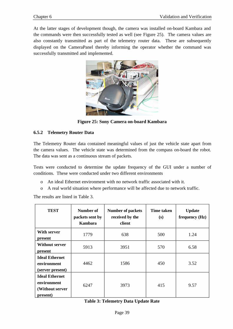
Chapter 6 Validation and Verification
Page 39
At the latter stages of development though, the camera was installed on-board Kambara andthe commands were then successfully tested as well (see Figure 25). The camera values arealso constantly transmitted as part of the telemetry router data. These are subsequentlydisplayed on the CameraPanel thereby informing the operator whether the command wassuccessfully transmitted and implemented.
Figure 25: Sony Camera on-board Kambara
6.5.2 Telemetry Router Data
The Telemetry Router data contained meaningful values of just the vehicle state apart fromthe camera values. The vehicle state was determined from the compass on-board the robot.The data was sent as a continuous stream of packets.
Tests were conducted to determine the update frequency of the GUI under a number ofconditions. These were conducted under two different environments
ο An ideal Ethernet environment with no network traffic associated with it.ο A real world situation where performance will be affected due to network traffic.
The results are listed in Table 3.
TEST Number ofpackets sent by
Kambara
Number of packetsreceived by the
client
Time taken(s)
Updatefrequency (Hz)
With serverpresent
1779 638 500 1.24
Without serverpresent
5913 3951 570 6.58
Ideal Ethernetenvironment(server present)
4462 1586 450 3.52
Ideal Ethernetenvironment(Without serverpresent)
6247 3973 415 9.57
Table 3: Telemetry Data Update Rate

Chapter 6 Validation and Verification
Page 40
The performance was not satisfactory when both the client and the server are located on thesame machine. The performance as expected is much better in an ideal Ethernet environmentwith an increase of around 2.5 to 3 Hz. This is primarily due to the network traffic, which isnot present in an ideal environment.
The server also affects the rate of GUI updates. This is due to the threads executed by theserver for obtaining information from the robot and passing that information onto the clients.
6.6 Control Modes
The observer, individual and teleoperation control modes were successfully implemented andtested. The first stage was examining the disconnected state. In this state, the user is unableto select any of the control modes on the pulldown menu.
Once the user is connected to the server, only the components relating to viewing the stateinformation were made visible. On selecting the Individual control mode, the user was able tomanipulate the motor torque values and also send camera commands to the robot throughbuttons that are added on the TelemetryPanel and the CameraPanel. In the Teleoperationmode, the NavigationPanel was made available to the operator as another tabbedPane.
Finally, the control and network aspects were combined and tested. Two clients wereconnected to the server with one of them given control of the robot. The other client made arequest for control by selecting the Individual Control option in the pulldown menu. Thisclient was refused control as expected. Also, control was relinquished when the controllingclient returned to the observer mode and the second client was subsequently able tosuccessfully obtain control of the robot.
6.7 Chapter Summary
This chapter detailed the testing procedures used for validating and verifying theimplementation of various aspects of the project. The applet was predominantly tested usingJava AppletViewer but it was loaded into a Java 2 compliant browser. The joystick testingwas concentrated on the computation of the rotations angles (roll, pitch, and yaw) with theMovementsPanel acting as a good feedback mechanism for determining the values.
A Sony D-230 camera was used for testing the camera commands and only during the latterstages of the implementation was the camera on-board the AUV. Telemetry router data wasreceived from Kambara. Network traffic and local execution of the Kambara server seriouslyaffect the GUI updates based on the telemetry data.
The next step is to draw conclusions including summarising the thesis and discussing mycontribution to the Kambara project (more specifically, the development of the operatorinterface). This is detailed in the next chapter, which also includes discussion about furtherwork that should be accomplished in order to successfully complete the operator interface.

Page 41
CCHHAAPPTTEERR 77:: CCOONNCCLLUUSSIIOONN AANNDD FFUURRTTHHEERR WWOORRKK
7.1 Conclusion
This project has continued the development of the operator interface for the Kambara project.Design and implementation of an applet has accomplished one of the main aims ofmanipulating Kambara over the Internet.
The redesign of the GUI along with increased use of Java 2 Swing libraries have increased theflexibility of the different components of the interface. The investigation of NCSA Portfoliofor using a VRML model of Kambara in place of the Wavefront model was unsuccessfulbecause of constraints imposed by the Java 3D API and NCSA Portfolio itself.
A software joystick has been developed to assist with the navigation of the robot. It willultimately also help with direct teleoperation of the AUV. The manipulations of the joystickare simulated using the 3D model. Because the development on-board Kambara has notreached a stage where it accepts navigation commands, these have not been implemented.
The interface receives telemetry router data from the robot in real time as opposed to asimulator7. Experiments were conducted for determining the update rate of the GUI. It isfound to be 6.58 Hz without server executing locally and 1.24 Hz with the server present onthe system. Network traffic also affects the updates as similar tests on an ideal Ethernetenvironment give update rates of 3.5 Hz (with the server present) and 9.57 Hz (without theserver on the system).
The network capabilities now also include the ability for the client to send camera commandsto the robot. These have been successfully tested with the Sony D-230 camera on-boardKambara.
The different control modes have also been implemented and successfully tested. Theindividual and teleoperation control modes have been enhanced as a result of the developmentof the software joystick and the successful implementation of the camera commands.
7.2 Contributions
One of the major contributions of my project is the development of the software joystick.Similar interfaces do not use such a mechanism for navigation. The joystick will beextremely useful in the areas of teleoperation and even supervisory control.
The implementation of obtaining state information data from Kambara is the second majorcontribution of my project. To date, the communication with Kambara had been simulated
7 The original system obtained its input from a simulator RSISE. A vector of the simulator data is provided inAppendix C

Chapter 7 Conclusion and Further Work
Page 42
with state information packets being received from an artificial source. Obtaining real timetelemetry router data and updating the GUI from that data has been one of the motivationsbehind the Kambara project.
Development of a means of sending commands to the robot is another important aspect of theoperator interface, a part of which has been accomplished through this project.
7.3 Further Work
There is still much work to be done in order to get the interface properly operational. Thisproject has focussed on the development of navigation mechanisms for moving the robot andalso ensuring that there is proper communication between the client and the robot. Thesefeatures, especially the camera commands have enhanced the control mode mechanismsavailable to the client. However, more work needs to be done especially in regard toobtaining live video from the robot.
7.2.1 Video Feed
The NavigationPanel8 contains the joystick but it has also been designed to provide live videoto the operator. With the camera commands having been implemented, images can beobtained depicting the current view of the camera. Live video is required to aid directteleoperation and in order to map a route for the robot (supervisory control).
7.2.2 Supervisory Control
A plan needs to be made for supervisory control mode especially now that the robot acceptscommands from the client. The use of the CameraPanel along with live video can facilitateplanning of a route for the robot, or execution of a series of commands in sequence. Thisshould be done in anticipation of future robot operations when an optic fibre tether is nolonger present.
7.2.3 Network Architecture
The current design is similar to the long-term goal that has been described in Chapter 4(Section 4.3), with one major difference. The protocol used for communication between theKambara server and the robot is UDP. While this protocol suits our purpose of getting thecommands easily and quickly to the robot and is extremely useful for testing, it is notadequate in the long term. This is because a much more reliable protocol is necessary in realtime situations.
Once Kambara is operational, it is imperative that most of the commands are received by therobot and acted upon. Therefore, further improvements with regard to the existing designneed to be implemented.
8 A snapshot of the NavigationPanel is available in Appendix E5

Chapter 7 Conclusion and Further Work
Page 43
7.2.4 Logging information
Presently, the logging system is in its primitive stages, with the menu option having beenestablished, but no logging actually commencing. The method of logging needs to beexamined. When the client is running as an applet, the Java security arrangements will notallow writing on a client’s system without their permission. Therefore, it may be desirable tohave a separate logging process running at the server end. File storage will also be a problemdue to the frequency and the amount of data being transmitted.

Page 44
BBIIBBLLIIOOGGRRAAPPHHYY
[1] McPherson, C., 1999. Network-based Operator Interface for an Underwater Robot.Department of Engineering Honours Project Thesis, ANU.
[2] Gaskett, C., Wettergreen, D., Zelinsky, A., 1998. Development of a Visually guidedAutonomous Underwater Vehicle. Oceans’ 98
[3] Gaskett, C., Wettergreen, D., Zelinsky, A., 1999. Reinforcement Learning for aVisually guided Autonomous Underwater Vehicle. International Symposium onUnmanned Untethered Submersibles Technology. New Hampshire, USA
[4] Kambara Software Design:http://wwwsyseng.anu.edu.au/rsl/sub/software/software_design.html
[5] Couch, J., 1999. Java 2 Networking. McGraw-Hill. New York
[6] Flanagan, D., 1996. Java in a Nutshell. O’Reilly and Associates. USA
[7] Lewis, J., Loftus, W., 1998. Java Software Solutions. Addison Wesley. USA
[8] Visual Design Resourceshttp://www.indiana.edu/%7Eiirg/ARTICLES/VIZRES/resource_page.html
[9] Java 1.2 API specification: http://java.sun.com/products/jdk/1.2/docs/api/index.html
[10] Java3D 1.1 API specification:http://java.sun.com/products/java-media/3D/forDevelopers/j3dapi/index.html
[11] Java Plug-in for Browsers: http://java.sun.com/products/plugin/
[12] NCSA Portfolio: http://www.ncsa.uiuc.edu/~srp/Java3D/portfolio/
[13] Web Interface for TeleScience: http://wits.jpl.nasa.gov/
[14] Bouvier, DJ., 1999. Getting started with the Java3D API. Sun Microsystems.
[15] Tanenbaum, AS., 1996, Computer Networks. Prentice-Hall of India Private Limited

Page 45
AAPPPPEENNDDIIXX AA:: NNCCSSAA PPOORRTTFFOOLLIIOO
NCSA Portfolio is a collection of utility objects to use within your Java3D programs. Someof the newer features available with NCSA Portfolio include,
• Input devices for Flock of Birds, Cave Wand, Spacetec SpaceOrb 360, MicrosoftForce Feedback Sidewinder, and mouse.
• Unified InputDevice Interface introduced
• New PickTool features for use with the Wand or SpaceOrb.
• New VTK ASCII loader
• New VTK binary loader (big endian only)
• New NFF loader
• New TextureCache object
Other NCSA Portfolio features include:
• Universal model loader interface: All supported 3D model types can be loadedthrough a single call to a ModelLoader object that acts as an interface to all 3D modelreaders. Supported loaders include
o NCSA's 3D Studio (3DS) loadero NCSA's AutoCAD DXF loader (Version 12)o NCSA's Protein Data Bank (PDB) loadero NCSA's Digital Elevation Map (DEM) loadero NCSA's Imagine (IOB) loadero NCSA's TrueSpace (COB) loader (Version 2)o NCSA's VRML 97 (WRL) loadero NCSA's PLAY loadero NCSA's VTK ASCII loadero NCSA's VTK binary loader (big endian only)o NCSA's NFF loadero NCSA's Wavefront OBJ (including material files for colours) loadero Sun’s Lightwave 3D Scene loader
You can also add your own loader interfaces, and the ModelLoader will automaticallyrecognise them.
• Unified InputDevice Interface: Starting in NCSA Portfolio release 1.3 beta 1, thereis support for a unified input device interface. Using this interface, we can create away to interchange input devices in programs without having to recompile theprogram itself. This is really useful if you are working on one device (say a desktop),and have to move the program to another type of device (such as a four-screenedPortal). Future releases are expected to individually address how buttons are mappedon input devices.

Appendix A NCSA Portfolio
Page 46
• Event management: The object library provides a mechanism for managing eventswithin Java 3D programs through the ToolManager and its Tools. UsingToolManager, application developers can easily switch between operating modes. Inthis release of NCSA Portfolio, we include a PickTool to manipulate 3D models in ascene and a ViewTool for changing the View within a scene. Application developerscan also write their own Tools to use with the ToolManager.
• Collaborative real-time updates: Imagine two people starting Java 3D programs ontwo different machines, and have either of them control the program! NCSA Portfolioincludes networking objects that allow you to easily create real-time collaborativeapplications.
• Canvas snapshots: Take a snapshot of the current Canvas3D view and save it as aJPEG file!
• Record and replay of application events: The NCSA Portfolio library can record theactions of Tools controlled by the ToolManager. Once the actions are recorded andsaved, they can be loaded and replayed. You can use this to script live animations.

Page 47
AAPPPPEENNDDIIXX BB:: UUSSEERR DDAATTAAGGRRAAMM PPRROOTTOOCCOOLL
UDP (User Datagram Protocol) is a connectionless protocol that provides a way forapplications to send encapsulated raw IP Datagrams and sends them without having toestablish a connection. Many client-server applications that have one request and oneresponse use UDP rather than go to the trouble of establishing and later releasing aconnection.
In UDP, you create a message to be sent, then create a UDP socket and tell it to send themessage to the destination. Once you have sent it, the socket cannot be used again. You willneed to create a new socket if you want to send more data (or packets).
At the destination end, the application will be listening for data on a UDP socket as well.Since the data from a UDP transmission is, by nature, a single packet, then we know that oncewe have received it, it can be processed immediately. However, just as in sending data, if wewant to listen for more information on that same port, then we must create a new UDP socketto replace the one that has just been used.
Therefore, if we need to create a new socket for each send and receive, then thecommunications can only be one way. That is, if the initial sender wanted to know if ananswer had been sent, then it too must create a listening UDP socket just like the receiver.
Once the receiver has been given the data, there may still be other problems. UDP does notinclude any form of error correction apart from what the lower-level standards may haveincluded. Therefore it is possible that the data you may receive nay have been corrupted insome way. You will need to make sure either that your custom protocol has some errormanagement built in, or that the application knows how to detect and ignore erroneousmessages without crashing.

Page 48
AAPPPPEENNDDIIXX CC:: VVEECCTTOORR OOFF SSIIMMUULLAATTOORR DDAATTAA
Field element / range (doubles) Data Represented
0-2 Vehicle Position x, y, z values
3-6 Vehicle Orientation (Quaternion)
7-9 Vehicle local velocity
10-12 Vehicle angular velocity
13-17 Motor torque
18-20 Vehicle target
21 Battery voltage
22-23 Accelerometer totals
24 Compass angle
25 Camera pan value
26 Camera tilt value
27 Camera zoom value
28-32 Motor current
33-37 Motor voltage
38-40 Derived accelerometer 1 u, v, w values
41-43 Derived accelerometer 2 u, v, w values
44-46 Raw accelerometer 1 u, v, w values
47-49 Raw accelerometer 1 u, v, w values
50-52 Compass magnetic disturbances

Page 49
AAPPPPEENNDDIIXX DD:: SSOOFFTTWWAARREE JJOOYYSSTTIICCKK DDEESSIIGGNN

Page 50
AAPPPPEENNDDIIXX EE11:: SSCCRREEEENNSSHHOOTT OOFF TTEELLEEMMEETTRRYYPPAANNEELL

Page 51
AAPPPPEENNDDIIXX EE22:: SSCCRREEEENNSSHHOOTT OOFF PPOOSSIITTIIOONNPPAANNEELL

Page 52
AAPPPPEENNDDIIXX EE33:: SSCCRREEEENNSSHHOOTT OOFF DDAATTAAPPAANNEELL
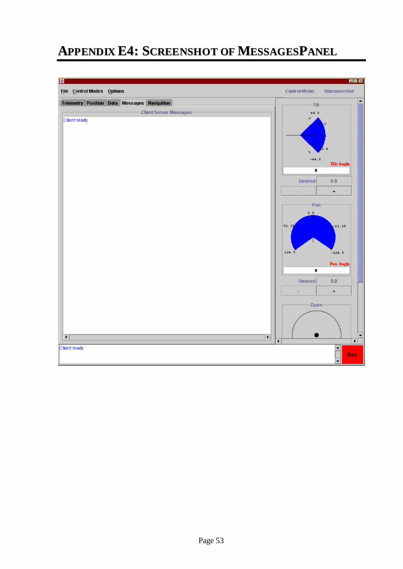
Page 53
AAPPPPEENNDDIIXX EE44:: SSCCRREEEENNSSHHOOTT OOFF MMEESSSSAAGGEESSPPAANNEELL

Page 54
AAPPPPEENNDDIIXX EE55:: SSCCRREEEENNSSHHOOTT OOFF NNAAVVIIGGAATTIIOONNPPAANNEELL

Page 55
AAPPPPEENNDDIIXX FF:: CCOONNTTEENNTTSS OOFF CCDD
There are four main directories in the CD. These are java3D, software, src and thesis. Thereis also a file called bookmarks2.html. It contains links to all the Internet sites used during theproject.
Directory Files / Subdirectories Description
Java3dAPI-documentation This folder contains the documentation of all theJava3D API 1.1 classes and libraries.
java3d-examples This folder has a few useful examples relating touse of Java3D. Prominent among these isInteraction, which shows manipulating of mousebehavior.
Java3D
java3d1_1_3_doc.zip Zip file for the Java3D API 1.1 DocumentationHtmlconv12.zip HTML converter for the Java 2 Plug-In.ncsaportfolio13beta3.jar Archive file containing NCSA Portfolio classes.
Also contains documentation similar to Java orJava3D documentation.
software
doc The documentation for the operator interface iscontained in this directory. It is generated usingthe javadoc utility in Java.
operInterface Java source code that has been used for thedevelopment of the operator interface. There aresix prominent directories – client, server,menus , components, control and joystick.
kambara3dq The simulator executableconfig.ini Configuration file for the simulator.
src
images All the images used in the thesis are stored in thisdirectory. The images have been further dividedin terms of the chapter that they belong to. Thereare a few backup images and a folder containingsome interface snapshots of 1999.
XfigDiagrams The xfig figures used in creating the images forthe thesis are contained in this folder. Theyinclude
Thesis.PDF My thesis document in PDF format.Thesis.doc My thesis document in WORD formatThesis-Outline.txt An outline of the thesis that was constructed at
the beginning of the process of the developmentof the thesis.
thesis
dsw-kambarainfo.txt David Wettergreen’s introduction to theKambara project.