the automated software phase-locked loop and …the automated software phase-locked loop and the...
TRANSCRIPT

THE AUTOMATED SOFTWARE PHASE-LOCKED LOOP AND THE
EXPLORATION OF AN ADAPTIVE ALGORITHM FOR THE
ADJUSTMENT OF PLL PARAMETERS
by
KEVIN MICHAEL ROLFES
A thesis submitted in partial fulfillment of
the requirements for the degree of
Master of Science
(Electrical Engineering)
at the
UNIVERSITY OF WISCONSIN - MADISON
1994
ii
ABSTRACT
Phase-locked loops are commonly used to measure the frequency of a sinusoid in the
presence of noise and to track the frequency of this signal as it changes. This
document describes the development of a software phase-locked loop and an
algorithm to automate the selection of PLL parameters based upon measurements of
the input signal. An adaptive algorithm for the adjustment of PLL parameters in real-
time is investigated.

iii
ACKNOWLEDGMENTS
The author wishes to thank the following individuals and institutions for their
contribution to this thesis:
Professor Richard A. Greiner, for technical guidance and support of this
project, and for the resources of the U.W. Electroacoustics Lab.
Digisonix, Inc., for funding this work and providing technical support, with
special thanks to Steven Popovich and Mark Allie for their feedback and suggestions
regarding proposed algorithms for adaptive control.
Professor Barry Van Veen, for technical guidance on the testing of adaptive
algorithms.
Fellow Electroacoustics Lab members Mitch Gebheim, Scott Kuhn, and Dave
Baumann, for their feedback and assistance throughout this project.
iv
TABLE OF CONTENTS
Chapter 1: A General Overview of the Phase-Locked Loop ......................... 1 1.1 Fundamentals of PLL Operation .................................................................... 1
1.1.1 Phase Detector ................................................................................. 2
1.1.2 Loop Filter ....................................................................................... 7
1.1.3 Voltage-Controlled Oscillator ......................................................... 9 1.2 Phase-Locked Loop Parameters ..................................................................... 10 1.3 Phase-Locked Loops and Noise ..................................................................... 13 Chapter 2: Software Implementation of a Fixed-Parameter PLL ................ 15 2.1 Emulation of Circular Memory Addressing .................................................. 15 2.2 The Phase Detector ........................................................................................ 19 2.3 The Loop Filter .............................................................................................. 20 2.4 Voltage-Controlled Oscillator ........................................................................ 28 2.5 Input Signal Conditioning .............................................................................. 31
2.5.1 Bandpass Filter ................................................................................ 32
2.5.2 Automatic Gain Control .................................................................. 36 2.6 Performance of the Software PLL ................................................................. 39 Chapter 3: The Lock Detector .......................................................................... 42

v
3.1 The Hilbert Transform ................................................................................... 42
3.1.1 A More Efficient Approach ............................................................. 47 3.2 Lock Detector Multiplier ............................................................................... 48 3.3 Variable Length Averaging Filter .................................................................. 49 Chapter 4: The Automated Selection of PLL Parameters ............................. 54 4.1 Overview of the Supervisor Algorithm ......................................................... 54 4.2 The Power Spectrum ...................................................................................... 66 4.3 Calculation of PLL Parameters ...................................................................... 70 4.4 Estimating the Signal-to-Noise Ratio ............................................................ 71 Chapter 5: The Exploration of an Adaptive Algorithm ................................. 85 5.1 VCO Center Frequency Adjustment .............................................................. 85 5.2 Adaptive Loop Filter ...................................................................................... 90
5.2.1 Performance of the Adaptive Loop Filter ........................................ 94
5.2.2 Adaptive Noise Canceler ................................................................. 110
5.2.3 Future Work ..................................................................................... 113 Appendix A: The Signal Generation Utility .................................................... 114 Appendix B: The Phase-Locked Loop Program ............................................. 118 Appendix C: References .................................................................................... 133
1
1 A General Overview of the Phase-Locked Loop
The phase-locked loop (PLL) is commonly used in applications that measure the
frequency, amplitude, and/or phase of a sinusoid in the presence of other signals or
random noise. For example, PLLs are often found in stereo FM receivers. In this
case, the PLL is tuned to the carrier frequency of a radio station that is modulated by
the audio signal. The PLL will track this input signal as it varies about the carrier
frequency, and can output this variation which we later hear as music. The
application driving this research is that of active noise control, in which sound waves
are attenuated by the production of a similar waveform with inverted polarity [1].
For some algorithms [2] it is necessary to know the frequency and phase of a
sinusoid to a high degree of precision to produce the appropriate wave for
cancellation.
1.1 FUNDAMENTALS OF PLL OPERATION
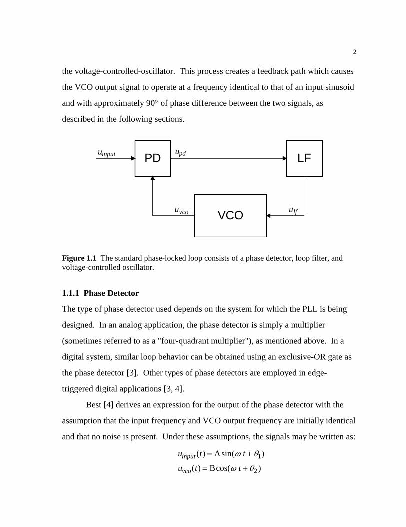
The standard PLL consists of three basic components: the phase detector (PD), loop
filter (LF), and voltage-controlled oscillator (VCO), as shown in Fig. 1.1. In analog
applications the phase detector consists of a simple multiplication stage, which
multiplies the input signal with the output of the voltage-controlled oscillator,
resulting in a DC component and a time-varying component. The loop filter
removes most of the AC component and applies some gain to the DC component of
the signal. The output of the loop filter then determines the operating frequency of
2
the voltage-controlled-oscillator. This process creates a feedback path which causes
the VCO output signal to operate at a frequency identical to that of an input sinusoid
and with approximately 90° of phase difference between the two signals, as
described in the following sections.
PD LF
VCO
u uinput pd
ulfuvco
Figure 1.1 The standard phase-locked loop consists of a phase detector, loop filter, and voltage-controlled oscillator.
1.1.1 Phase Detector
The type of phase detector used depends on the system for which the PLL is being
designed. In an analog application, the phase detector is simply a multiplier
(sometimes referred to as a "four-quadrant multiplier"), as mentioned above. In a
digital system, similar loop behavior can be obtained using an exclusive-OR gate as
the phase detector [3]. Other types of phase detectors are employed in edge-
triggered digital applications [3, 4].
Best [4] derives an expression for the output of the phase detector with the
assumption that the input frequency and VCO output frequency are initially identical
and that no noise is present. Under these assumptions, the signals may be written as:
u t t
u t tinput
vco
( ) sin( )
( ) cos( )
= +
= +
A
B
ω θ
ω θ1
2

3
After multiplication, the phase detector output is:
u t tpd ( ) [sin( ) sin( )]= − + + +K AB d
221 2 1 2θ θ ω θ θ
where Kd is the gain applied by the phase detector. The DC component of the phase
detector output is linearly dependent upon the sine of the phase difference between
uinput and uvco. If θ1 is greater than θ2, this DC component will be positive and the
VCO will increase in frequency, thus reducing the phase difference between these
two signals. Similarly, if θ1 is less than θ2, the DC component will be negative
which causes the VCO to decrease in frequency, also reducing the phase difference.
In this manner the VCO output frequency is adjusted until the phase difference
between the two signals has been minimized. This is known as the "pull-in" process.
The VCO output frequency is equal to the input frequency when the phase
difference is a constant, since an angular frequency ω is defined as the time
derivative of phase θ. Furthermore, since the input and VCO output signals have
been defined with sine and cosine, respectively, a zero phase difference between θ1
and θ2 indicates a 90° phase shift between the input signal and the VCO output
signal.
4
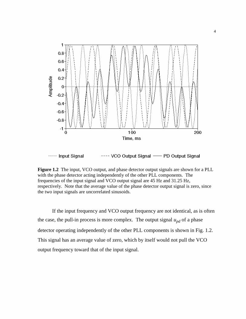
Figure 1.2 The input, VCO output, and phase detector output signals are shown for a PLL with the phase detector acting independently of the other PLL components. The frequencies of the input signal and VCO output signal are 45 Hz and 31.25 Hz, respectively. Note that the average value of the phase detector output signal is zero, since the two input signals are uncorrelated sinusoids.
If the input frequency and VCO output frequency are not identical, as is often
the case, the pull-in process is more complex. The output signal upd of a phase
detector operating independently of the other PLL components is shown in Fig. 1.2.
This signal has an average value of zero, which by itself would not pull the VCO
output frequency toward that of the input signal.
5
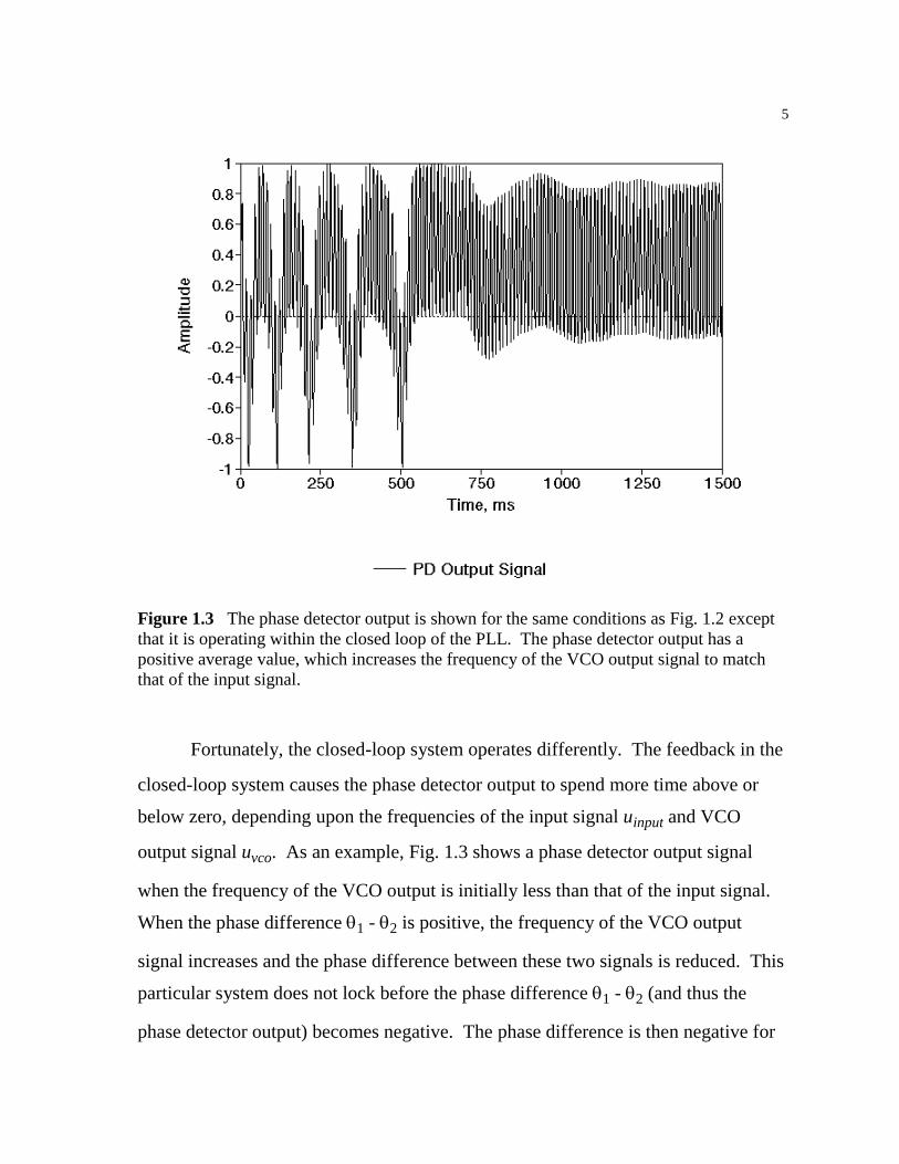
Figure 1.3 The phase detector output is shown for the same conditions as Fig. 1.2 except that it is operating within the closed loop of the PLL. The phase detector output has a positive average value, which increases the frequency of the VCO output signal to match that of the input signal.
Fortunately, the closed-loop system operates differently. The feedback in the
closed-loop system causes the phase detector output to spend more time above or
below zero, depending upon the frequencies of the input signal uinput and VCO
output signal uvco. As an example, Fig. 1.3 shows a phase detector output signal
when the frequency of the VCO output is initially less than that of the input signal.
When the phase difference θ1 - θ2 is positive, the frequency of the VCO output
signal increases and the phase difference between these two signals is reduced. This
particular system does not lock before the phase difference θ1 - θ2 (and thus the
phase detector output) becomes negative. The phase difference is then negative for

6
one-half the period of the beat frequency. In this region the frequency of the VCO
output signal is decreased. This causes the frequency of uvco to decrease, which
increases the difference in frequency between uinput and uvco. The beat frequency
then increases, reducing the time that the phase detector output is negative. The
opposite occurs when the phase detector output is positive. As the frequency of uvco
is increased, the beat frequency is reduced, increasing the amount of time that the
phase detector output is positive. This process repeats, gradually pulling the
frequency of the VCO output signal toward that of the input signal.
Figure 1.4 The input, VCO output, and phase detector output signals are shown for the system of Fig. 1.3 after the PLL has locked. The nonzero phase difference between the input and VCO output signals maintains the necessary positive average value of the phase detector output signal.
7
The input, VCO output, and phase detector output signals after the system has
locked are shown in Fig. 1.4. While the phase difference between the input and
VCO output signals has been minimized, it is not zero. In this case, a positive
average value of the phase detector output must be maintained for the frequency of
the VCO output signal to match that of the input signal. This indicates that a
nonzero phase difference is necessary for the PLL to stay locked. The minimum
attainable phase difference approaches zero as the frequency of the input signal
approaches the VCO center frequency, ωo (see section 1.1.3 for details of VCO
operation).
1.1.2 Loop Filter
In an analog phase-locked loop, a low-pass filter is used to attenuate the AC
component of the phase detector output. Since the output of the loop filter becomes
the input signal for the voltage-controlled oscillator, it is important that this AC
component be reduced to prevent unnecessary frequency modulation of the VCO
output signal.
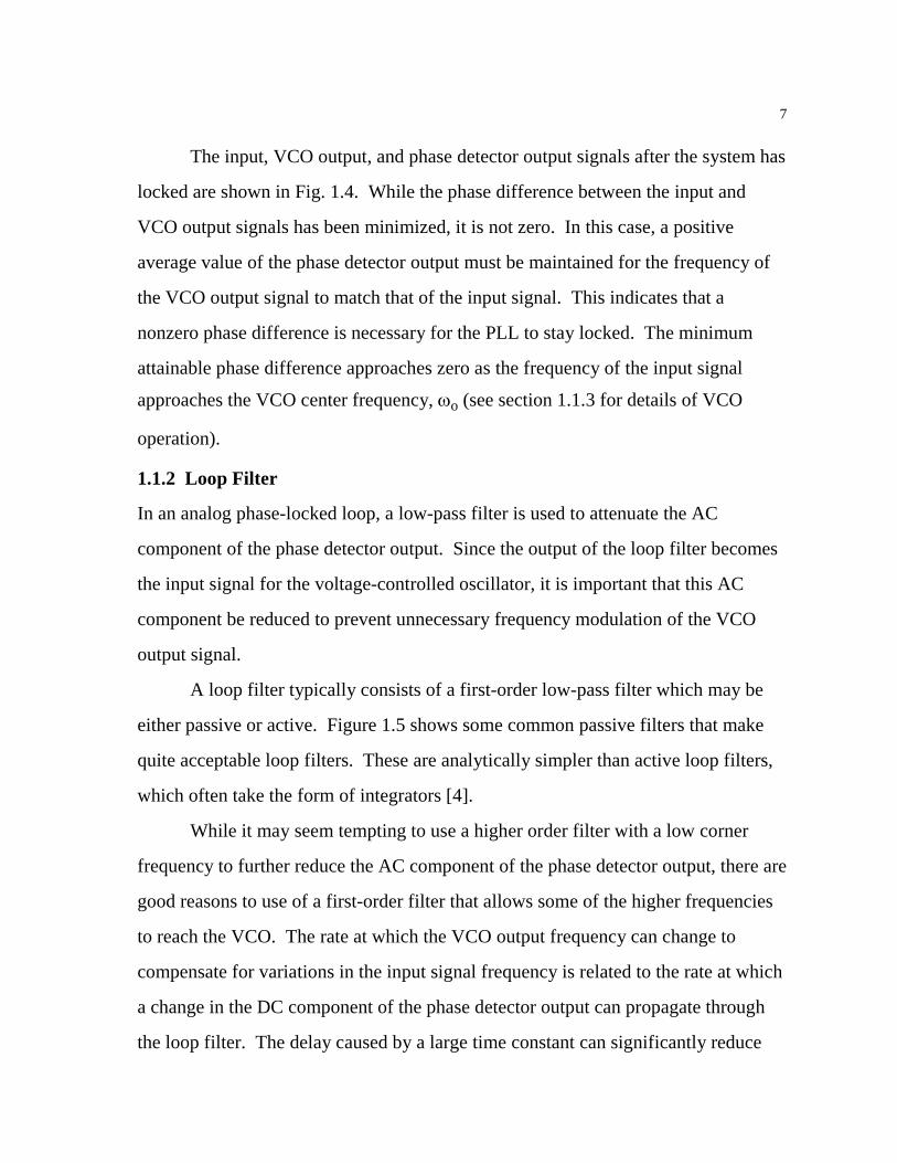
A loop filter typically consists of a first-order low-pass filter which may be
either passive or active. Figure 1.5 shows some common passive filters that make
quite acceptable loop filters. These are analytically simpler than active loop filters,
which often take the form of integrators [4].
While it may seem tempting to use a higher order filter with a low corner
frequency to further reduce the AC component of the phase detector output, there are
good reasons to use of a first-order filter that allows some of the higher frequencies
to reach the VCO. The rate at which the VCO output frequency can change to
compensate for variations in the input signal frequency is related to the rate at which
a change in the DC component of the phase detector output can propagate through
the loop filter. The delay caused by a large time constant can significantly reduce
8
the ability of the phase-locked loop to remain locked when the frequency of the
input signal changes. A low corner frequency reduces the unwanted modulation of
the VCO output signal but sacrifices some of the PLL tracking ability. A high
corner frequency provides greater tracking ability but makes the VCO output signal
more susceptible to modulation by noise and other undesired signals. This is the
fundamental tradeoff that must be considered in the design of the loop filter.
R1
R1
C
C
R2
H(j )ω
H(j )ωupd
lfuupd
lfu
ω
ω
a.
b.
11CR
11 2C RR( )+
12CR
Figure 1.5 Two passive filters are shown with the frequency response of each. These first order low-pass filters are commonly used as loop filters in analog phase-locked loops.
The transfer functions of the filters shown in Fig. 1.5a and 1.5b are:
H( )jj
ωω
=+
111CR

9
and
H( )( )
j jj
ωω
ω=
++ +
CRC R R
2
1 2
11
respectively. The frequency responses of these filters are similar except for the
introduction of a zero in the second filter. This allows for greater control of the
frequency response of the loop filter, which will prove to be useful in the selection
of PLL parameters.
1.1.3 Voltage-Controlled Oscillator
The voltage-controlled oscillator (VCO) produces an output signal with a frequency
that is linearly dependent upon an input signal. This signal is often considered to be
the output of the phase-locked loop, since its frequency will track that of the input
signal.
While the VCO output signal is usually sinusoidal, other waveforms are also
used. Digital applications often require a square wave output as a clock for
synchronous logic. In the application of a phase-locked loop for noise cancellation,
the tone to be canceled is a sinusoid, so a sinusoidal VCO output is chosen. The
sinusoidal VCO is preferred since the higher order harmonics of the square wave
will propagate through the phase detector and loop filter, contributing towards
unnecessary frequency modulation of the VCO.
For this application, the VCO output signal is given by the expression
+= ∫ tdttutu
tlfvco oo )(Ksin)( ω
where ulf(t) is the loop filter output, Ko is the gain applied to the VCO input signal,
and ωo is the VCO center frequency. This center frequency specifies the frequency
of the output signal when the input is zero. It is this quantity that determines the
center of the frequency band over which the PLL can operate.
10
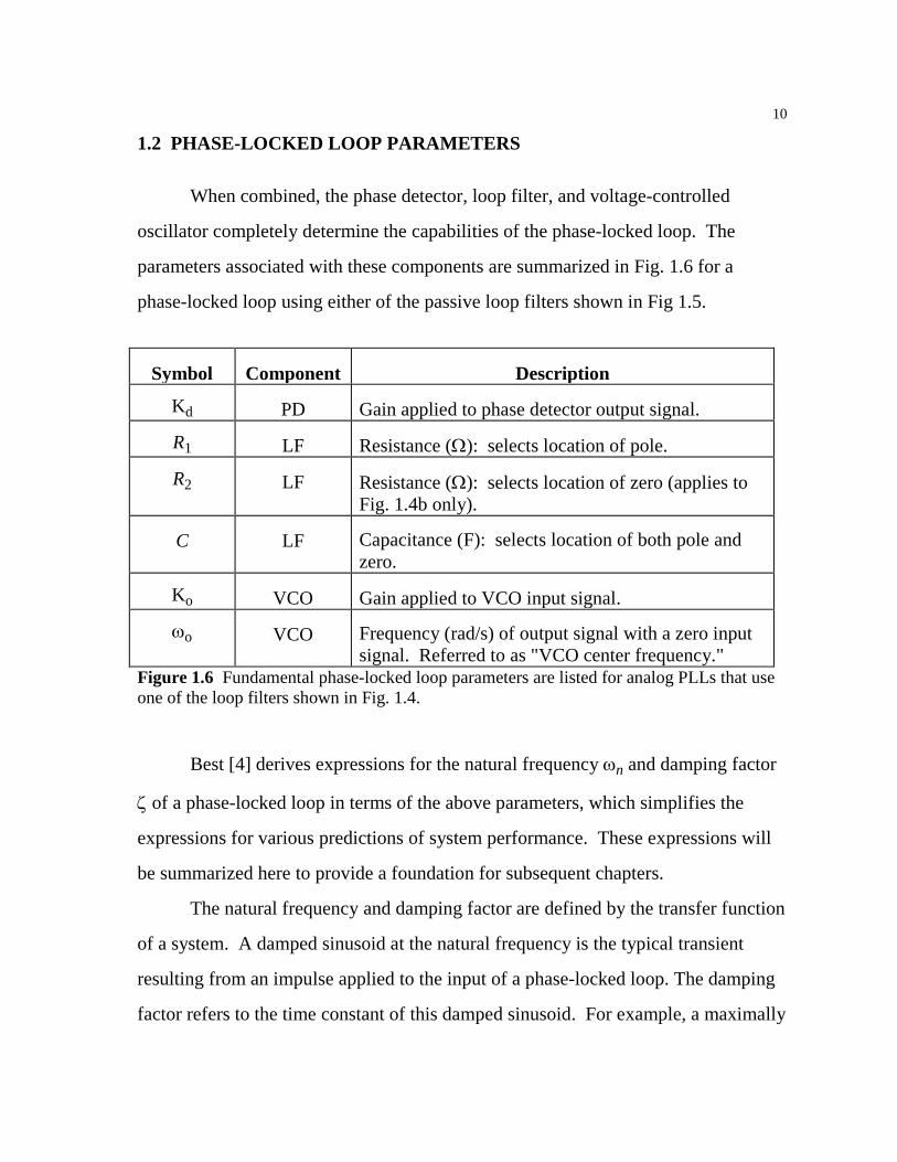
1.2 PHASE-LOCKED LOOP PARAMETERS
When combined, the phase detector, loop filter, and voltage-controlled
oscillator completely determine the capabilities of the phase-locked loop. The
parameters associated with these components are summarized in Fig. 1.6 for a
phase-locked loop using either of the passive loop filters shown in Fig 1.5.
Symbol Component Description
Kd PD Gain applied to phase detector output signal.
R1 LF Resistance (Ω): selects location of pole.
R2 LF Resistance (Ω): selects location of zero (applies to Fig. 1.4b only).
C LF Capacitance (F): selects location of both pole and zero.
Ko VCO Gain applied to VCO input signal.
ωo VCO Frequency (rad/s) of output signal with a zero input signal. Referred to as "VCO center frequency."
Figure 1.6 Fundamental phase-locked loop parameters are listed for analog PLLs that use one of the loop filters shown in Fig. 1.4.
Best [4] derives expressions for the natural frequency ωn and damping factor
ζ of a phase-locked loop in terms of the above parameters, which simplifies the
expressions for various predictions of system performance. These expressions will
be summarized here to provide a foundation for subsequent chapters.
The natural frequency and damping factor are defined by the transfer function
of a system. A damped sinusoid at the natural frequency is the typical transient
resulting from an impulse applied to the input of a phase-locked loop. The damping
factor refers to the time constant of this damped sinusoid. For example, a maximally

11
flat system will have a damping factor of 0.707. Systems with smaller damping
factors will exhibit more ringing, while those with larger damping factors will have
fewer oscillations in exchange for a longer settling time. A maximally flat system is
normally seen as a suitable compromise to achieve a small amount of ringing while
retaining a low settling time.
For a phase-locked loop using the loop filter shown in Fig. 1.5a, the natural
frequency and damping factor are:
ωτ
ζτ
n =
=⋅
K K
2 K K
o d
o d
1
1
1 1
where τ1 1= R C . Using the loop filter of Fig. 1.5b, these expressions become
ωτ τ
ζω τ
n
n
=+
=+
K K
(K KK K
o d
o d
o d
1 2
2 12
)
where τ1 1= R C and τ2 2= R C . It is now apparent that the additional zero of the
second filter provides more flexibility since ωn and ζ may be set independently.
The operation of the phase-locked loop is normally limited to a narrow
bandwidth known as the lock range. This frequency range, centered about the VCO
center frequency ωo, is the region in which the PLL will lock to the input signal
uinput within a single period of the beat frequency between the input signal and VCO
output signal. The lock range, ∆ωL, is equal to the natural frequency ωn for a phase-
locked loop using the loop filter of Fig. 1.5a. For the loop filter of Fig. 1.5b, the
lock range is 2ζωn. For maximally flat systems (ζ = 0.707) the lock range for a PLL

12
with the loop filter of Fig. 1.5b is approximately 1.4 times greater than that of the
PLL using the simpler loop filter of Fig. 1.5a. The locking process for a PLL with
an input sinusoid within the lock range is shown in Fig. 1.7.
Figure 1.7 When the input signal is within the lock range, ∆ωL, the phase-locked loop will lock within a single period of the beat frequency between the input signal and the VCO output signal. In this case, the input signal is 45 Hz and the VCO output signal is initially 31.25 Hz. Compare this to the slower lock of Figure 1.3, in which the input signal falls within the pull-in range but is outside the lock range.
There is a frequency range larger than the lock range within which the PLL
may not lock within a single period of the beat frequency. In this range the PLL will
gradually adjust the frequency of the VCO output signal to match that of the input

13
signal. This is known as the pull-in range, ∆ωP, and was illustrated in Fig. 1.3. For
any phase-locked loop, the pull-in range is:
∆ωπ
ζω ωP o dK K≈ −8 2
n n
The hold range, ∆ωH, is normally larger than both ∆ωL and ∆ωP. This
defines the maximum frequency range over which the phase-locked loop can operate
with a nonvarying input signal. A lock is not guaranteed within this range, but it is
possible. For a phase-locked loop using a passive loop filter, the hold range is equal
to K Ko d. This indicates that a large loop gain, which is the product of the phase
detector output gain Kd and the VCO input gain Ko, is necessary for the phase-
locked loop to remain stable over a wide range of input frequencies.
These frequency ranges assume a nonvarying input signal. The phase-locked
loop will remain locked to a varying input signal that falls within these ranges, but
the rate of change must be less than the square of the natural frequency:
ddtinput
nω
ω< 2
1.3 PHASE-LOCKED LOOPS AND NOISE
An uncorrelated noise signal superimposed on the input signal will displace the
phase detector output from the value it would otherwise have. This displacement is
known as phase jitter. If the noise is excessive, the PLL may not be able to maintain
a lock on the input signal.
The bandwidth of the incoming noise is typically limited by a filter applied to
the input signal before it reaches the phase detector. In a discrete-time
implementation the bandwidth is also limited by the anti-aliasing filter in series with

14
the analog-to-digital converter. The bandwidth of the noise on the input signal is
denoted Bi.
Furthermore, the loop filter of the phase-locked loop imposes a restriction on
the bandwidth of the noise in the loop. This bandwidth, BL, is given by Best [4] as:
+=
ζζ
ω41
2n
LB
Best also shows that the signal-to-noise ratio inside the loop is larger than the
signal-to-noise ratio of the input signal when BL is less than half of Bi.
SNR SNRloop inputi
L
BB
=2
While increasing ωn and ζ may improve the lock range of the phase-locked
loop, it can be seen from the above expressions that this also increases the
bandwidth of the noise in the loop. The allowable lock range is thus dependent upon
the amount of noise present on the input signal.
Finally, Best claims that a lock is possible with an SNRloop of 2, but that a
signal-to-noise ratio of at least 4 is generally preferred for stable operation.
15
2 Software Implementation of a Fixed-Parameter PLL
The software implementation of a fixed-parameter phase-locked loop serves as a
foundation for further study of automation and adaptive algorithms. This is an ideal
platform for development work since any combination of signals can be saved to
disk for later analysis. In this case, the software simulates the behavior of a phase-
locked loop and reads the input signal from a data file. The code is written in small
modules without global variables to provide maximum flexibility for further
development and is intended to be easily portable to a digital signal processor such
as the Texas Instruments' TMS320C3X or 4X.
2.1 EMULATION OF CIRCULAR MEMORY ADDRESSING
Many digital signal processors, including the TMS320C3X and 4X, support a form
of circular memory addressing. This allows a data buffer to be updated by simply
overwriting the oldest value with a new value and modifying a pointer to indicate the
start or end of the data buffer. This pointer wraps around from the highest to the
lowest address (or vice-versa) when it exceeds the boundaries of the data buffer.
Circular addressing thus allows for a computationally efficient method of
maintaining a buffer for a sampled signal.
The Intel 80X86 platform used for these simulations does not intrinsically
support circular addressing. Since the phase-locked loop software is intended to be
easily ported to a DSP system, code was developed to provide the capabilities of
16
circular addressing through software. This imposes a speed penalty on the
performance of the software. However, speed is a lower priority than the portability
and flexibility of the simulation software. In this software, circular buffers were
used for nearly all phase-locked loop signals. While this further increased the
execution time, the development time of various algorithms was reduced by using
such data buffers.
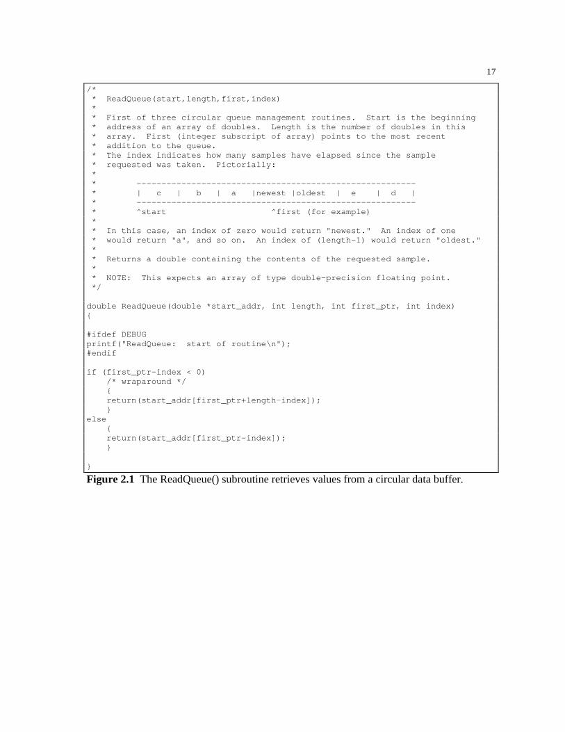
The circular addressing routines require the lowest address of the buffer, the
buffer length, and an index representing the location of the newest sample in the
buffer. Three routines are provided: ReadQueue(), WriteQueue(), and
PushQueue(). ReadQueue() and WriteQueue() are used to access data buffers
without altering the index of the newest sample. PushQueue() is used to overwrite
the oldest value in the data buffer with a new value. The index of the newest sample
is modified accordingly.
17
/* * ReadQueue(start,length,first,index) * * First of three circular queue management routines. Start is the beginning * address of an array of doubles. Length is the number of doubles in this * array. First (integer subscript of array) points to the most recent * addition to the queue. * The index indicates how many samples have elapsed since the sample * requested was taken. Pictorially: * * -------------------------------------------------------- * | c | b | a |newest |oldest | e | d | * -------------------------------------------------------- * ^start ^first (for example) * * In this case, an index of zero would return "newest." An index of one * would return "a", and so on. An index of (length-1) would return "oldest." * * Returns a double containing the contents of the requested sample. * * NOTE: This expects an array of type double-precision floating point. */ double ReadQueue(double *start_addr, int length, int first_ptr, int index) #ifdef DEBUG printf("ReadQueue: start of routine\n"); #endif if (first_ptr-index < 0) /* wraparound */ return(start_addr[first_ptr+length-index]); else return(start_addr[first_ptr-index]);
Figure 2.1 The ReadQueue() subroutine retrieves values from a circular data buffer.
18
/* * WriteQueue(start,length,first,index,value); * * 2nd of three circular queue management routines. Start is the beginning * address of an array of doubles. Length is the number of doubles in this * array. First is the subscript of the most recent addition to the queue. * The index indicates how many samples have elapsed since the sample * of interest was taken. The contents of "value" will replace the * contents of this cell. Pictorially: * * -------------------------------------------------------- * | c | b | a |newest |oldest | e | d | * -------------------------------------------------------- * ^start ^first (for example) * * In this case, an index of zero would overwrite "newest." An index of one * would overwrite "a", and so on. An index of (length-1) would overwrite * "oldest." * * NOTE: This expects an array of type double-precision floating point. */ void WriteQueue(double *start_addr, int length, int first_ptr, int index, double value) #ifdef DEBUG printf("WriteQueue: start of routine\n"); #endif if (first_ptr-index < 0) /* wraparound */ start_addr[first_ptr+length-index]=value; else start_addr[first_ptr-index]=value;
Figure 2.2 The WriteQueue() routine overwrites values in a circular data buffer without modifying the index which indicates the location of the newest sample.

19
/* * PushQueue(start,length,first,value); * * Last of three circular queue management routines. Start is the beginning * address of an array of doubles. Length is the number of doubles in this * array. First is the subscript of the most recent addition to the queue. * The index indicates how many samples have elapsed since the sample * of interest was taken. The contents of "value" will replace the * contents of this cell. Pictorially: * * -------------------------------------------------------- * | c | b | a |newest |oldest | e | d | * -------------------------------------------------------- * ^start ^first (for example) * * The pointer 'first' will be moved one cell to the right, wrapping to * 'start' if required. The contents of 'value' will overwrite the oldest * sample. The new 'first' pointer will be returned. * * NOTE: This expects an array of type double-precision floating point. */ int PushQueue(double *start_addr, int length, int first_ptr, double value) #ifdef DEBUG printf("PushQueue: start of routine\n"); #endif /* increment first_ptr */ first_ptr++; if (first_ptr >= length) first_ptr=0; start_addr[first_ptr]=value; return(first_ptr);
Figure 2.3 The PushQueue() routine overwrites the oldest sample in a circular data buffer with a new sample, modifying the index of the newest sample accordingly.
2.2 THE PHASE DETECTOR
As described in section 1.1, the phase detector for an analog phase-locked loop
consists of a simple multiplication of the input signal with the VCO output signal.
The software implementation is no less straightforward. The circular buffers
containing the input signal and VCO output signal are sent to PhaseDetector(),
which multiplies the most recent sample in each data buffer and stores the resulting
product in the data buffer of the output signal.

20
/* * int PhaseDetector(double *filtered_input, int filtered_input_length * , int filtered_input_ptr, double *vco_output, int vco_output_length * , int vco_output_ptr, double *pre_loop_filter * , int pre_loop_filter_length, int pre_loop_filter_ptr) * * Phase detector of PLL: an analog multiplier. We just multiply the * most recent samples in filtered_input[] and vco_output[] and store the * result in pre_loop_filter[]. * * The updated pointer for the circular queue pre_loop_filter is returned. */ int PhaseDetector(double *filtered_input, int filtered_input_length , int filtered_input_ptr, double *vco_output, int vco_output_length , int vco_output_ptr, double *pre_loop_filter , int pre_loop_filter_length, int pre_loop_filter_ptr) double last_fil,last_vco; last_fil=ReadQueue(filtered_input, filtered_input_length, filtered_input_ptr,0); last_vco=ReadQueue(vco_output, vco_output_length, vco_output_ptr, 0); return(PushQueue(pre_loop_filter, pre_loop_filter_length, pre_loop_filter_ptr , last_fil*last_vco));
Figure 2.4 The PhaseDetector() routine simply multiplies the most recent samples of the input signal and VCO output signal.
2.3 THE LOOP FILTER
A digital equivalent of the loop filter shown in Fig. 1.5b is used for the fixed-
parameter phase-locked loop. In a subsequent chapter it is also used as the initial
condition for an adaptive loop filter. This filter was selected because it may be
transformed into a digital FIR filter and because it allows ωn and ζ to be chosen
independently.
The step-invariant method of filter design [5] was used to transform the
transfer function of the Fig. 1.5b filter into an IIR filter. The sampled impulse
response of this filter then provides the coefficients for the FIR filter. The
transformation is summarized here, beginning with the transfer function for the Fig.
1.5b loop filter:
H( )s ss
=+
+ +τ
τ τ2
1 2
11( )
21
Applying the unit step and expanding the expression into partial fractions, 1 1
11
1 2s s s sH( ) ( )= +−
+ +τ
τ τ
taking the inverse Laplace transform,
( )nT21
1-1 e1)H(1
21
1L ττ
τττ +
−
+−
+=ss
and converting this expression into the Z-domain while moving the unit step to the
right-hand side provides the equivalent IIR filter.
( ) ( )
+−
+−
−=−−
−
+−
121
11
1
211
e-1
11
11)H(zz
zzTττττ
τ
After some rearranging, this may be written as:
( ) ( )
−
+−
+=−
−
− +−
+−
1
1
121
1
211
211
e-1e-1
11)H(z
z
zz
TT τττττττ
An inverse Z-transform then produces the FIR filter coefficients:
( ) ( )21)1(
21 e)1u(e)()(21
1
21
1 ττττ
τττ
τττδ +
−−+−
−
+
+
+−
+=TnnT
nnnTh
These coefficients are calculated by the CreateFilterTaps() subroutine, which fills an
array with the filter coefficients based upon the sampling frequency, filter length,
and the parameters τ1 and τ2. The filter coefficients take the form of a decaying
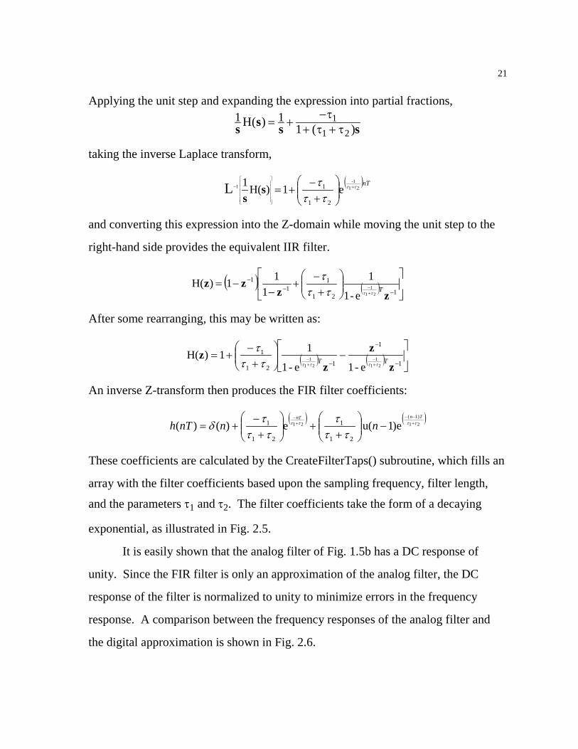
exponential, as illustrated in Fig. 2.5.
It is easily shown that the analog filter of Fig. 1.5b has a DC response of
unity. Since the FIR filter is only an approximation of the analog filter, the DC
response of the filter is normalized to unity to minimize errors in the frequency
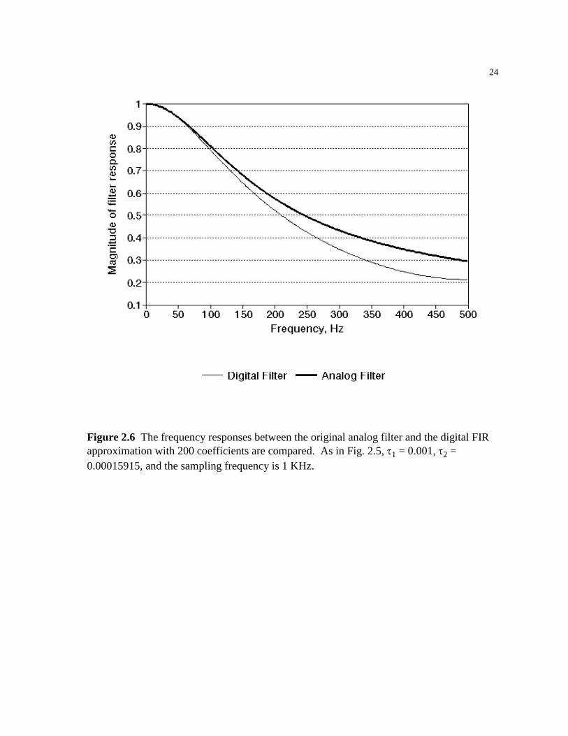
response. A comparison between the frequency responses of the analog filter and
the digital approximation is shown in Fig. 2.6.
22
The gain of this filter Kd is determined by a parameter which is sent to
FilterSignal(). Because the taps are normalized for a DC gain of unity, the DC gain
of this filter is exactly specified by this gain parameter. The loop gain of the phase-
locked loop is the product of the gains of the loop filter and the voltage-controlled-
oscillator. Since the operation of the phase-locked loop depends only upon the
product and not the individual gains, the software implementation of the phase-
locked loop is simplified by setting the VCO gain Ko to unity and using the loop
filter gain Kd to control the loop gain. Thus, the loop gain will be referred to as
KoKd in subsequent chapters with no reference to the individual contributions of the
VCO or loop filter.

23
Figure 2.5 These graphs illustrate the first twelve filter coefficients for the digital FIR approximation of the filter shown in Fig. 1.5b, with τ1 = 0.001, τ2 = 0.00015915, and a sampling frequency of 1 KHz.
24
Figure 2.6 The frequency responses between the original analog filter and the digital FIR approximation with 200 coefficients are compared. As in Fig. 2.5, τ1 = 0.001, τ2 = 0.00015915, and the sampling frequency is 1 KHz.
25
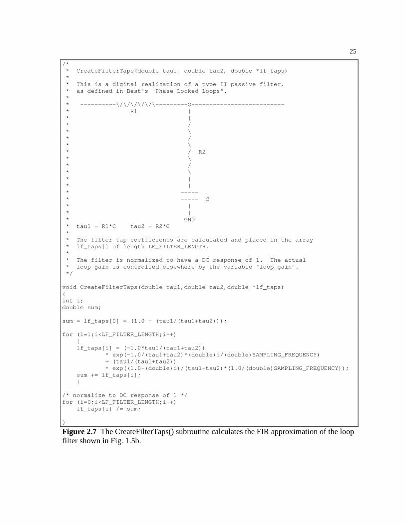
/* * CreateFilterTaps(double tau1, double tau2, double *lf_taps) * * This is a digital realization of a type II passive filter, * as defined in Best's "Phase Locked Loops". * * ----------\/\/\/\/\/\---------O-------------------------- * R1 | * | * / * \ * / * \ * / R2 * \ * / * \ * | * | * ----- * ----- C * | * | * GND * tau1 = R1*C tau2 = R2*C * * The filter tap coefficients are calculated and placed in the array * lf_taps[] of length LF_FILTER_LENGTH. * * The filter is normalized to have a DC response of 1. The actual * loop gain is controlled elsewhere by the variable "loop_gain". */ void CreateFilterTaps(double tau1,double tau2,double *lf_taps) int i; double sum; sum = lf_taps[0] = (1.0 - (tau1/(tau1+tau2))); for (i=1;i<LF_FILTER_LENGTH;i++) lf_taps[i] = (-1.0*tau1/(tau1+tau2)) * exp(-1.0/(tau1+tau2)*(double)i/(double)SAMPLING_FREQUENCY) + (tau1/(tau1+tau2)) * exp((1.0-(double)i)/(tau1+tau2)*(1.0/(double)SAMPLING_FREQUENCY)); sum += lf_taps[i]; /* normalize to DC response of 1 */ for (i=0;i<LF_FILTER_LENGTH;i++) lf_taps[i] /= sum;
Figure 2.7 The CreateFilterTaps() subroutine calculates the FIR approximation of the loop filter shown in Fig. 1.5b.
26
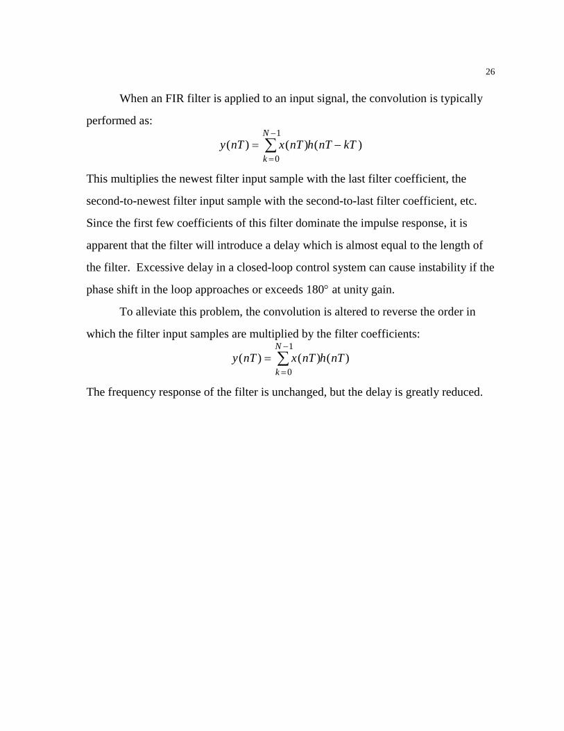
When an FIR filter is applied to an input signal, the convolution is typically
performed as:
y nT x nT h nT kTk
N( ) ( ) ( )= −
=
−
∑0
1
This multiplies the newest filter input sample with the last filter coefficient, the
second-to-newest filter input sample with the second-to-last filter coefficient, etc.
Since the first few coefficients of this filter dominate the impulse response, it is
apparent that the filter will introduce a delay which is almost equal to the length of
the filter. Excessive delay in a closed-loop control system can cause instability if the
phase shift in the loop approaches or exceeds 180° at unity gain.
To alleviate this problem, the convolution is altered to reverse the order in
which the filter input samples are multiplied by the filter coefficients:
y nT x nT h nTk
N( ) ( ) ( )=
=
−
∑0
1
The frequency response of the filter is unchanged, but the delay is greatly reduced.
27
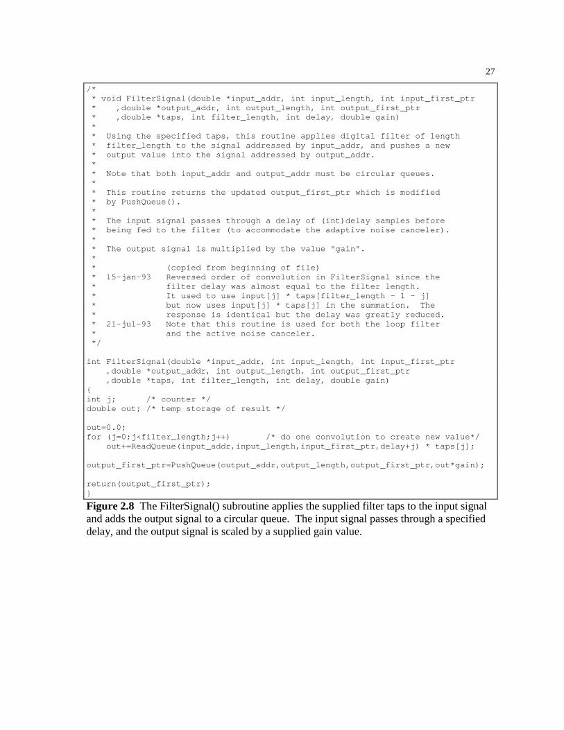
/* * void FilterSignal(double *input_addr, int input_length, int input_first_ptr * ,double *output_addr, int output_length, int output_first_ptr * ,double *taps, int filter_length, int delay, double gain) * * Using the specified taps, this routine applies digital filter of length * filter_length to the signal addressed by input_addr, and pushes a new * output value into the signal addressed by output_addr. * * Note that both input_addr and output_addr must be circular queues. * * This routine returns the updated output_first_ptr which is modified * by PushQueue(). * * The input signal passes through a delay of (int)delay samples before * being fed to the filter (to accommodate the adaptive noise canceler). * * The output signal is multiplied by the value "gain". * * (copied from beginning of file) * 15-jan-93 Reversed order of convolution in FilterSignal since the * filter delay was almost equal to the filter length. * It used to use input[j] * taps[filter_length - 1 - j] * but now uses input[j] * taps[j] in the summation. The * response is identical but the delay was greatly reduced. * 21-jul-93 Note that this routine is used for both the loop filter * and the active noise canceler. */ int FilterSignal(double *input_addr, int input_length, int input_first_ptr ,double *output_addr, int output_length, int output_first_ptr ,double *taps, int filter_length, int delay, double gain) int j; /* counter */ double out; /* temp storage of result */ out=0.0; for (j=0;j<filter_length;j++) /* do one convolution to create new value*/ out+=ReadQueue(input_addr,input_length,input_first_ptr,delay+j) * taps[j]; output_first_ptr=PushQueue(output_addr,output_length,output_first_ptr,out*gain); return(output_first_ptr);
Figure 2.8 The FilterSignal() subroutine applies the supplied filter taps to the input signal and adds the output signal to a circular queue. The input signal passes through a specified delay, and the output signal is scaled by a supplied gain value.

28
2.4 VOLTAGE-CONTROLLED OSCILLATOR
A discrete-time software implementation of the VCO was developed by
incrementing a phase angle θ(t) around the unit circle. Two independent values are
added to this phase angle. The first is a fixed value which determines the center
frequency ωo that the VCO will output when the input signal is zero. The second is
based upon the output of the loop filter. Since the gain Ko is set to unity, the
instantaneous frequency of the VCO output signal uvco is equal to the center
frequency ωo plus the output signal ulf of the loop filter. The equations for the phase
angle and output signal are then:
θ θω
θ
( ) ( )( )
( ) sin( ( ))
t tu tf
u t t
lf
s
vco
= − ++
=
1 o
A noteworthy observation is that the frequency of the VCO output signal uvco
can operate with a negative frequency for brief periods of time. This phenomena is
found in phase-locked loops that have a loop gain KoKd larger than the center
frequency ωo. The length of time that the VCO output frequency is negative is less
than the period of the input signal uinput. While this may make the VCO output
signal less desirable, the PLL is operating normally and will remain locked on the
input signal provided that uinput falls within the hold range of the PLL. If the
instantaneous frequency of uvco is somehow prevented from going negative, the
average frequency of uvco will not match the frequency of the input signal and the
PLL will unlock. Figure 2.9 shows the input signal and VCO output signal for a
PLL which remains locked with occasional negative frequencies in the signal uvco.
Since uvco is often used as the output signal of the phase-locked loop, it is
desirable to minimize the frequency modulation of the VCO. When there is very

29
little noise superimposed on the input signal uinput, a small loop gain may be used.
This reduces the modulation of the VCO, thus reducing the differences between
uinput and uinput.
The VCO() subroutine implements the sinusoidal voltage-controlled
oscillator and adds the sine of the phase angle to a circular buffer. A second
subroutine, CosineVCO(), adds the cosine of the phase angle to a circular buffer.
This is used to implement a 90° phase shift for use in later algorithms.
Figure 2.9 The input signal and VCO output signal are shown for a phase-locked loop which has a high gain and low center frequency, causing the VCO output signal to intermittently operate with a negative frequency. For this PLL, KoKd = 60, ωn = 30 rad/s, ζ = 0.707, ωo = 20 rad/s, and the input signal is a sinusoid at 11 rad/s.
30
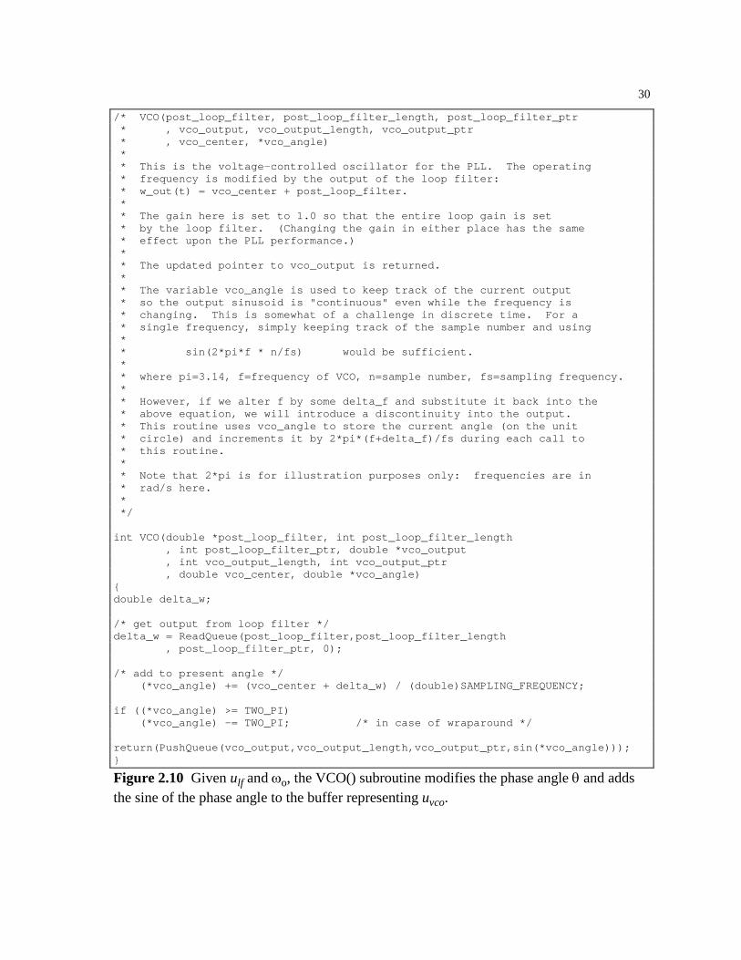
/* VCO(post_loop_filter, post_loop_filter_length, post_loop_filter_ptr * , vco_output, vco_output_length, vco_output_ptr * , vco_center, *vco_angle) * * This is the voltage-controlled oscillator for the PLL. The operating * frequency is modified by the output of the loop filter: * w_out(t) = vco_center + post_loop_filter. * * The gain here is set to 1.0 so that the entire loop gain is set * by the loop filter. (Changing the gain in either place has the same * effect upon the PLL performance.) * * The updated pointer to vco_output is returned. * * The variable vco_angle is used to keep track of the current output * so the output sinusoid is "continuous" even while the frequency is * changing. This is somewhat of a challenge in discrete time. For a * single frequency, simply keeping track of the sample number and using * * sin(2*pi*f * n/fs) would be sufficient. * * where pi=3.14, f=frequency of VCO, n=sample number, fs=sampling frequency. * * However, if we alter f by some delta_f and substitute it back into the * above equation, we will introduce a discontinuity into the output. * This routine uses vco_angle to store the current angle (on the unit * circle) and increments it by 2*pi*(f+delta_f)/fs during each call to * this routine. * * Note that 2*pi is for illustration purposes only: frequencies are in * rad/s here. * */ int VCO(double *post_loop_filter, int post_loop_filter_length , int post_loop_filter_ptr, double *vco_output , int vco_output_length, int vco_output_ptr , double vco_center, double *vco_angle) double delta_w; /* get output from loop filter */ delta_w = ReadQueue(post_loop_filter,post_loop_filter_length , post_loop_filter_ptr, 0); /* add to present angle */ (*vco_angle) += (vco_center + delta_w) / (double)SAMPLING_FREQUENCY; if ((*vco_angle) >= TWO_PI) (*vco_angle) -= TWO_PI; /* in case of wraparound */ return(PushQueue(vco_output,vco_output_length,vco_output_ptr,sin(*vco_angle)));
Figure 2.10 Given ulf and ωo, the VCO() subroutine modifies the phase angle θ and adds the sine of the phase angle to the buffer representing uvco.

31
/* CosineVCO(double *vco_shifted, int vco_shifted_length, int vco_shifted_ptr * , double vco_shifted_gain, double vco_angle); * * This is a carbon copy of the above VCO, and uses the same vco_angle * but generates a cosine output instead of the sine output of VCO(). * * The output amplitude of this VCO is set by the vco_shifted_gain * variable. * * The updated pointer to vco_shifted is returned. */ CosineVCO(double *vco_shifted, int vco_shifted_length, int vco_shifted_ptr , double vco_shifted_gain, double vco_angle) return(PushQueue(vco_shifted, vco_shifted_length, vco_shifted_ptr , vco_shifted_gain*cos(vco_angle)));
Figure 2.11 The CosineVCO() subroutine adds the cosine of the phase angle θ to a circular buffer for use in later algorithms.
2.5 INPUT SIGNAL CONDITIONING
The phase-locked loop has the remarkable ability to track signals in the presence of
noise. The performance of the PLL can be improved, however, by preprocessing of
the input signal. A bandpass filter which is centered about the frequency of interest
can improve the signal-to-noise ratio of the input signal. This allows for the use of a
lower loop gain, reducing the frequency modulation of the VCO output signal.
Since the input signal propagates through the phase detector and loop filter, the loop
gain of a PLL can be increased or decreased by changes in the amplitude of the input
signal. An automatic gain control (AGC) is used to normalize the amplitude of the
input signal.
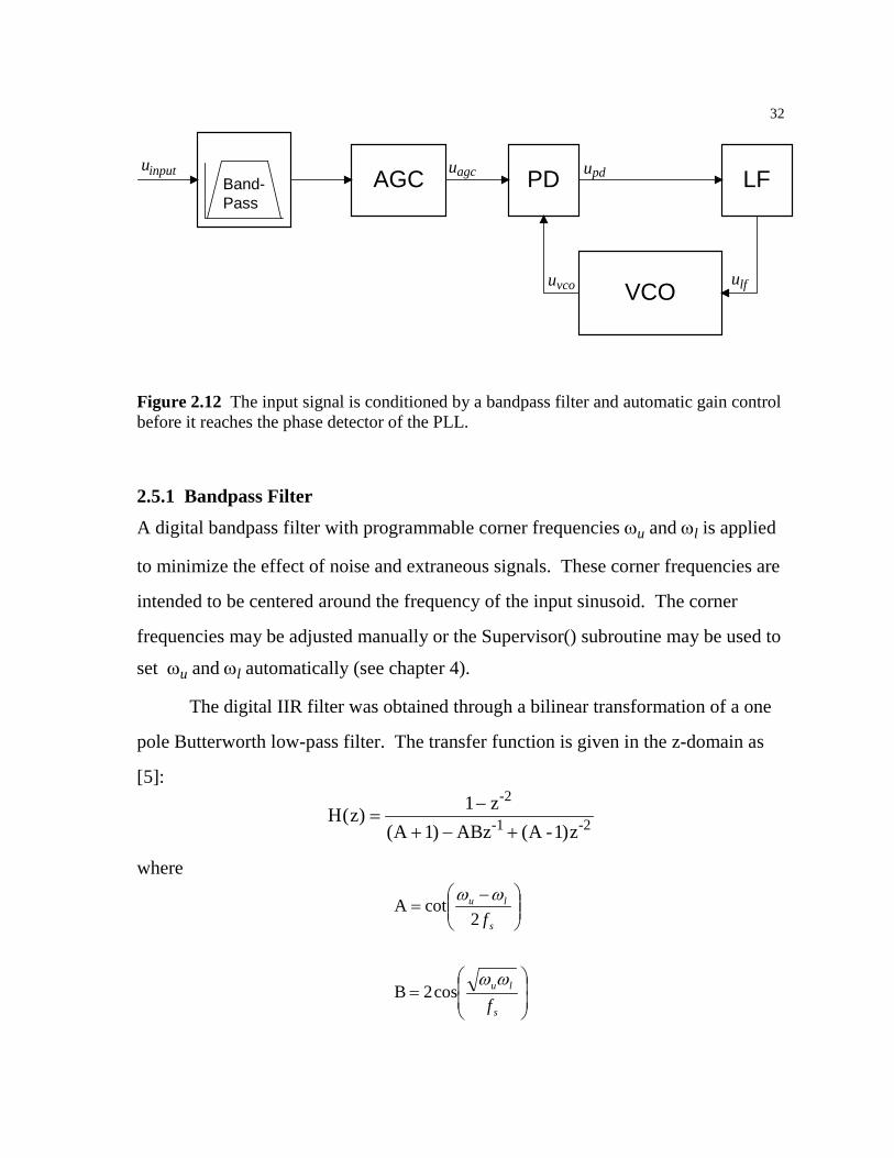
The block diagram of the phase-locked loop with the bandpass filter and
automatic gain control is shown in Fig. 2.12.
32
PD LF
VCO
Band-Pass
AGCu u
uu
uinput agc
vco lf
pd
Figure 2.12 The input signal is conditioned by a bandpass filter and automatic gain control before it reaches the phase detector of the PLL.
2.5.1 Bandpass Filter
A digital bandpass filter with programmable corner frequencies ωu and ωl is applied
to minimize the effect of noise and extraneous signals. These corner frequencies are
intended to be centered around the frequency of the input sinusoid. The corner
frequencies may be adjusted manually or the Supervisor() subroutine may be used to
set ωu and ωl automatically (see chapter 4).
The digital IIR filter was obtained through a bilinear transformation of a one
pole Butterworth low-pass filter. The transfer function is given in the z-domain as
[5]:
H(z zA ABz A -1)z
-2
-1 -2)( ) (
=−
+ − +1
1 where
=
−=
s
lu
s
lu
f
f
ωω
ωω
cos2B
2cotA
33
This may be expressed in the time domain as:
y nT x nT x nT T y nT T y nT T( ) ( ) ( ) ( ) ( ) ( )=+
− − + − − − −1
12 1 2
AAB A
The frequency response of this filter with corner frequencies set to 100 Hz
and 200 Hz is shown in Fig. 2.14. The automatic gain control compensates for the
nonunity gain in the passband of this filter.
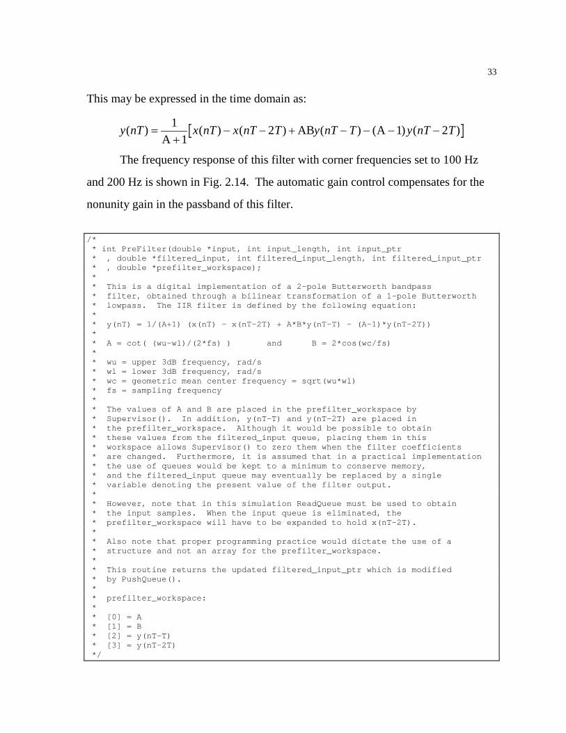
/* * int PreFilter(double *input, int input_length, int input_ptr * , double *filtered_input, int filtered_input_length, int filtered_input_ptr * , double *prefilter_workspace); * * This is a digital implementation of a 2-pole Butterworth bandpass * filter, obtained through a bilinear transformation of a 1-pole Butterworth * lowpass. The IIR filter is defined by the following equation: * * y(nT) = 1/(A+1) (x(nT) - x(nT-2T) + A*B*y(nT-T) - (A-1)*y(nT-2T)) * * A = cot( (wu-wl)/(2*fs) ) and B = 2*cos(wc/fs) * * wu = upper 3dB frequency, rad/s * wl = lower 3dB frequency, rad/s * wc = geometric mean center frequency = sqrt(wu*wl) * fs = sampling frequency * * The values of A and B are placed in the prefilter_workspace by * Supervisor(). In addition, y(nT-T) and y(nT-2T) are placed in * the prefilter_workspace. Although it would be possible to obtain * these values from the filtered_input queue, placing them in this * workspace allows Supervisor() to zero them when the filter coefficients * are changed. Furthermore, it is assumed that in a practical implementation * the use of queues would be kept to a minimum to conserve memory, * and the filtered_input queue may eventually be replaced by a single * variable denoting the present value of the filter output. * * However, note that in this simulation ReadQueue must be used to obtain * the input samples. When the input queue is eliminated, the * prefilter_workspace will have to be expanded to hold x(nT-2T). * * Also note that proper programming practice would dictate the use of a * structure and not an array for the prefilter_workspace. * * This routine returns the updated filtered_input_ptr which is modified * by PushQueue(). * * prefilter_workspace: * * [0] = A * [1] = B * [2] = y(nT-T) * [3] = y(nT-2T) */
34
int PreFilter(double *input, int input_length, int input_ptr , double *filtered_input, int filtered_input_length, int filtered_input_ptr , double *prefilter_workspace) double out; /* temp storage of result */ out = 1./(prefilter_workspace[0] + 1.) * ( ReadQueue(input, input_length, input_ptr, 0) - ReadQueue(input, input_length, input_ptr, 2) + prefilter_workspace[0]*prefilter_workspace[1]*prefilter_workspace[2] - (prefilter_workspace[0]-1.)*prefilter_workspace[3] ); filtered_input_ptr=PushQueue(filtered_input, filtered_input_length , filtered_input_ptr, out); prefilter_workspace[3] = prefilter_workspace[2]; prefilter_workspace[2] = out; return(filtered_input_ptr);
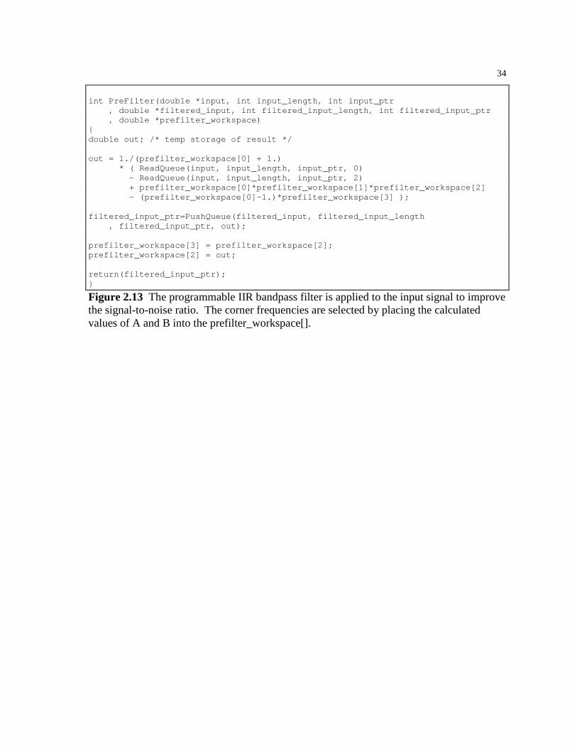
Figure 2.13 The programmable IIR bandpass filter is applied to the input signal to improve the signal-to-noise ratio. The corner frequencies are selected by placing the calculated values of A and B into the prefilter_workspace[].

35
Figure 2.14 The frequency response of the digital IIR bandpass filter is shown for a filter with the lower and upper corner frequencies set to 100 Hz and 200 Hz, respectively. (fs = 1 KHz)

36
2.5.2 Automatic Gain Control
Automatic gain control, or AGC, is applied after the bandpass filter to subtract any
DC offset and provide a relatively constant signal amplitude. It is desired that the
input sinusoid leave the AGC with a known amplitude. Unfortunately, the input
sinusoid is buried in an unknown amount of noise, and the AGC cannot distinguish
between signal and noise. As a result, the AGC cannot determine the amplitude of
the sinusoid. The AGC can, however, adjust the gain to keep the RMS value of the
output signal uagc constant. The amplitude of the output sinusoid will then depend
upon the amount of noise in the system, but it will be constant for a given noise
power.
The AGC first computes the average value of the input signal and subtracts
this value from the newest input sample, removing any DC offset that may be
present. With the DC removed, the RMS value of the time-varying component can
be computed. The gain is modified to keep this RMS value at a constant level. The
software uses an RMS value of 0.707 to allow a noiseless sinusoid to leave the AGC
with a peak amplitude of 1. The amount that the DC offset and gain are allowed to
change is limited to a fixed percentage per iteration to prevent rapid changes in the
signal seen by the PLL. These values are set conservatively to minimize any
interaction between the adjustments of the AGC and the operation of the PLL. The
change per iteration of the DC offset is limited to 0.5% of the difference between the
average value of the input signal and the DC offset used in the previous iteration.
The gain applied to the input signal after DC removal is limited to a 1% change per
iteration. This reflects the assumption that the signal amplitude will vary more than
the DC offset in an HVAC environment. Figure 2.15 illustrates the DC offset and
gain adjustment in response to an input signal with a DC offset of 1 and peak
amplitude of 4.

37
Figure 2.15 The AGC adjusts the gain and compensates for the DC offset of an input sinusoid with an amplitude of 4 and a DC offset of 1.
38
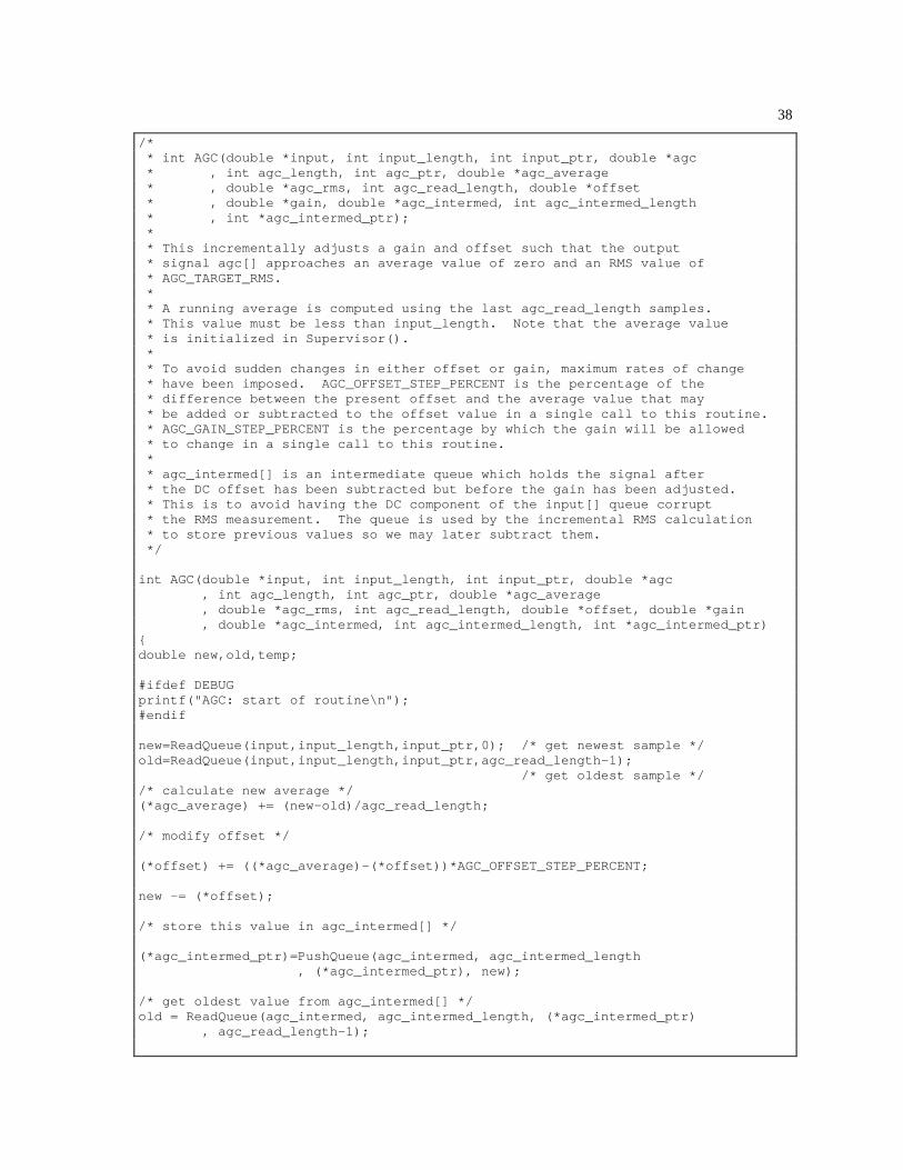
/* * int AGC(double *input, int input_length, int input_ptr, double *agc * , int agc_length, int agc_ptr, double *agc_average * , double *agc_rms, int agc_read_length, double *offset * , double *gain, double *agc_intermed, int agc_intermed_length * , int *agc_intermed_ptr); * * This incrementally adjusts a gain and offset such that the output * signal agc[] approaches an average value of zero and an RMS value of * AGC_TARGET_RMS. * * A running average is computed using the last agc_read_length samples. * This value must be less than input_length. Note that the average value * is initialized in Supervisor(). * * To avoid sudden changes in either offset or gain, maximum rates of change * have been imposed. AGC_OFFSET_STEP_PERCENT is the percentage of the * difference between the present offset and the average value that may * be added or subtracted to the offset value in a single call to this routine. * AGC_GAIN_STEP_PERCENT is the percentage by which the gain will be allowed * to change in a single call to this routine. * * agc_intermed[] is an intermediate queue which holds the signal after * the DC offset has been subtracted but before the gain has been adjusted. * This is to avoid having the DC component of the input[] queue corrupt * the RMS measurement. The queue is used by the incremental RMS calculation * to store previous values so we may later subtract them. */ int AGC(double *input, int input_length, int input_ptr, double *agc , int agc_length, int agc_ptr, double *agc_average , double *agc_rms, int agc_read_length, double *offset, double *gain , double *agc_intermed, int agc_intermed_length, int *agc_intermed_ptr) double new,old,temp; #ifdef DEBUG printf("AGC: start of routine\n"); #endif new=ReadQueue(input,input_length,input_ptr,0); /* get newest sample */ old=ReadQueue(input,input_length,input_ptr,agc_read_length-1); /* get oldest sample */ /* calculate new average */ (*agc_average) += (new-old)/agc_read_length; /* modify offset */ (*offset) += ((*agc_average)-(*offset))*AGC_OFFSET_STEP_PERCENT; new -= (*offset); /* store this value in agc_intermed[] */ (*agc_intermed_ptr)=PushQueue(agc_intermed, agc_intermed_length , (*agc_intermed_ptr), new); /* get oldest value from agc_intermed[] */ old = ReadQueue(agc_intermed, agc_intermed_length, (*agc_intermed_ptr) , agc_read_length-1);
39
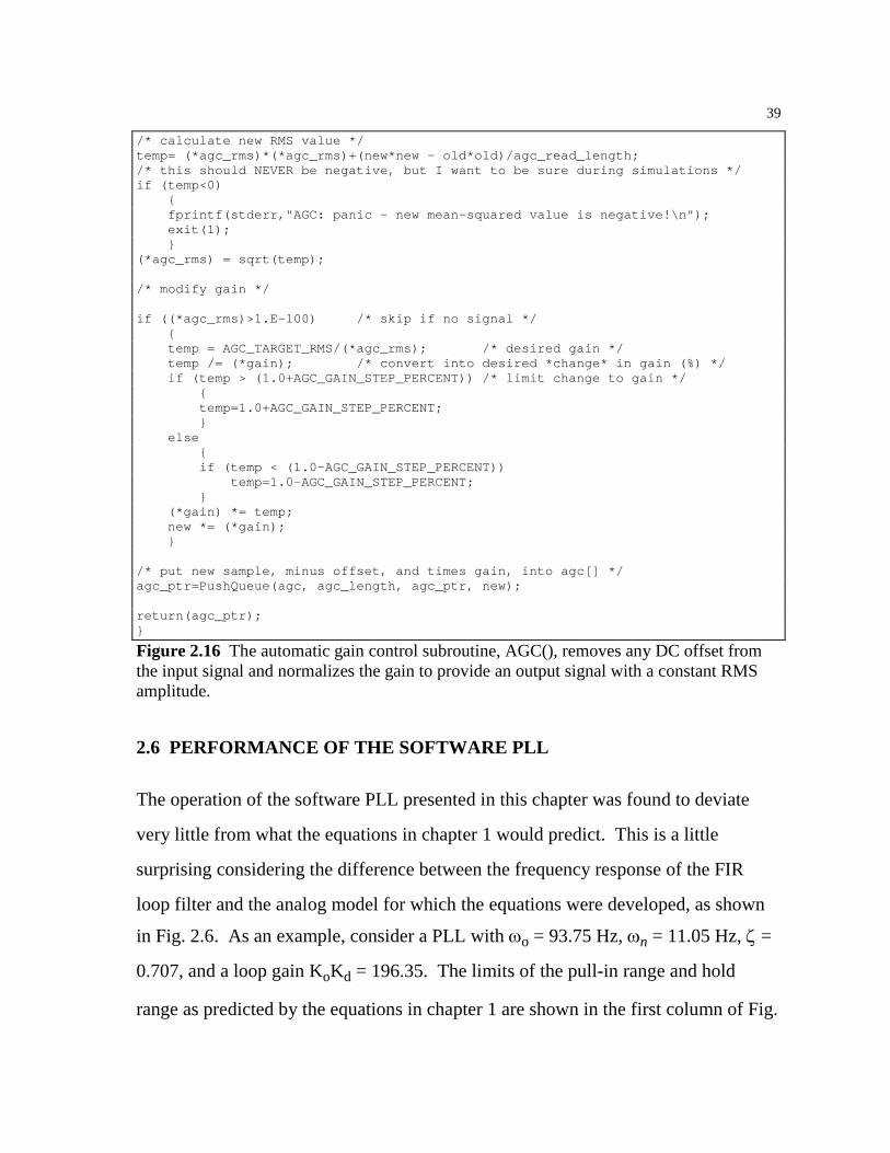
/* calculate new RMS value */ temp= (*agc_rms)*(*agc_rms)+(new*new - old*old)/agc_read_length; /* this should NEVER be negative, but I want to be sure during simulations */ if (temp<0) fprintf(stderr,"AGC: panic - new mean-squared value is negative!\n"); exit(1); (*agc_rms) = sqrt(temp); /* modify gain */ if ((*agc_rms)>1.E-100) /* skip if no signal */ temp = AGC_TARGET_RMS/(*agc_rms); /* desired gain */ temp /= (*gain); /* convert into desired *change* in gain (%) */ if (temp > (1.0+AGC_GAIN_STEP_PERCENT)) /* limit change to gain */ temp=1.0+AGC_GAIN_STEP_PERCENT; else if (temp < (1.0-AGC_GAIN_STEP_PERCENT)) temp=1.0-AGC_GAIN_STEP_PERCENT; (*gain) *= temp; new *= (*gain); /* put new sample, minus offset, and times gain, into agc[] */ agc_ptr=PushQueue(agc, agc_length, agc_ptr, new); return(agc_ptr);
Figure 2.16 The automatic gain control subroutine, AGC(), removes any DC offset from the input signal and normalizes the gain to provide an output signal with a constant RMS amplitude.
2.6 PERFORMANCE OF THE SOFTWARE PLL
The operation of the software PLL presented in this chapter was found to deviate
very little from what the equations in chapter 1 would predict. This is a little
surprising considering the difference between the frequency response of the FIR
loop filter and the analog model for which the equations were developed, as shown
in Fig. 2.6. As an example, consider a PLL with ωo = 93.75 Hz, ωn = 11.05 Hz, ζ =
0.707, and a loop gain KoKd = 196.35. The limits of the pull-in range and hold
range as predicted by the equations in chapter 1 are shown in the first column of Fig.
40
2.17. The input signal to the software PLL was slowly swept up and down through
the operating range of the PLL to find the experimental limits of these ranges. The
frequency at which the PLL was first able to lock is used as the extent of the pull-in
range, and the frequency at which the PLL unlocked is used as the extent of the hold
range. (The lock range is difficult to determine experimentally, since it falls within
the pull-in range and is distinguished only by the amount of time the PLL requires to
lock.) The experimentally obtained ranges are shown in the second column of Fig.
2.17. The differences between the theoretical and experimentally obtained values
are shown in the third column. The differences are quite small at most 1.14 Hz or
1.06%.
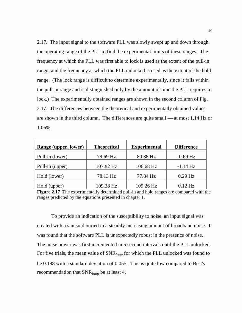
Range (upper, lower) Theoretical Experimental Difference
Pull-in (lower) 79.69 Hz 80.38 Hz -0.69 Hz
Pull-in (upper) 107.82 Hz 106.68 Hz -1.14 Hz
Hold (lower) 78.13 Hz 77.84 Hz 0.29 Hz
Hold (upper) 109.38 Hz 109.26 Hz 0.12 Hz Figure 2.17 The experimentally determined pull-in and hold ranges are compared with the ranges predicted by the equations presented in chapter 1.
To provide an indication of the susceptibility to noise, an input signal was
created with a sinusoid buried in a steadily increasing amount of broadband noise. It
was found that the software PLL is unexpectedly robust in the presence of noise.
The noise power was first incremented in 5 second intervals until the PLL unlocked.
For five trials, the mean value of SNRloop for which the PLL unlocked was found to
be 0.198 with a standard deviation of 0.055. This is quite low compared to Best's
recommendation that SNRloop be at least 4.
41
The same procedure was repeated with the noise power incremented in 20
second intervals. As expected, the mean SNRloop at which the PLL unlocked was
higher than in the previous trials since the longer intervals gave the PLL a greater
chance to unlock at each noise level. Five trials were again performed, in which the
mean SNRloop for which the PLL unlocked was found to be 0.287 with a standard
deviation of 0.067. This provides an estimate of a lower limit of the SNRloop for
proper operation of the software PLL. For reliable operation, it is suggested that a
higher signal-to-noise ratio be maintained through the use of a bandpass filter on the
input signal.

42
3 The Lock Detector
A method of determining if the PLL is locked or unlocked is needed before the
phase-locked loop can be automated. As seen in chapters 1 and 2, the input signal
uagc and the VCO output signal uvco are approximately 90° out of phase when the
PLL is locked. If the input signal is shifted by 90° and multiplied with the output of
the VCO, the resulting product will have an average positive value when the PLL is
locked. Otherwise, these two signals are uncorrelated and the product will have an
average value of zero [4]. A Hilbert transform is used to implement the required 90°
phase shift on the AGC output signal uagc, and a variable-length averaging filter is
used to provide a lock detector output signal ulock that may be used to determine if
the PLL is locked or unlocked. A block diagram of the lock detector is shown in
Fig. 3.1.
3.1 THE HILBERT TRANSFORM
It is well-known that a Hilbert transform will shift the phase of a signal by 90° while
leaving the amplitude unchanged. A Hilbert transform can be implemented with an
FIR filter with coefficients given by [6]:
0 0)(
0 sin2
)( 22
==
≠=
nnh
nn
nhn
π
π
This expression has been implemented in the FillHilbert() subroutine, which is
shown in Fig. 3.2. This routine calculates the FIR filter coefficients necessary to

43
perform a Hilbert Transform. These filter coefficients have odd symmetry about the
origin, as illustrated by the output of the FillHilbert() subroutine shown in Fig. 3.3.
The n = 0 value is shifted to the midpoint of the FIR filter to preserve symmetry.
This imposes a delay equal to half the length of the FIR filter, which is compensated
by an equivalent delay on the VCO output signal before the multiplication takes
place. A Hamming window is applied to the FIR filter coefficients to reduce the
effects caused by a finite length window being applied to the above expression.
PD LF
VCO
Band-Pass
AGC
HilbertTransform Low-
Pass
uinput
locku
Figure 3.1 The output of the lock detector has a positive average value while the PLL is locked, and an average value of zero when the PLL is unlocked.

44
/* * void FillHilbert(double *hilbert); * * Initializes HILBERT_LENGTH locations in hilbert[] with the taps * necessary for a Hilbert transform. This is used to phase shift * the incoming signal 90 degrees for use in lock detection. * * The taps are derived from x(n)=2.0/(PI*n) for n odd, zero otherwise. * The equivalent expression used here (Oppenheim, Schafer) is: * h(n) = 2 * (sin(PI*n/2))^2 / (PI*n) for n != 0 * h(n) = 0 for n = 0 * * The zero point is the center of the array, (HILBERT_LENGTH+1)/2. */ void FillHilbert(double *hilbert) int i; for (i=0;i<HILBERT_LENGTH;i++) if (i-(HILBERT_LENGTH-1)/2) /* if nonzero */ hilbert[i]=2.0/(PI*(double)(i-(HILBERT_LENGTH-1)/2)) * pow(sin(PI*(double)(i-(HILBERT_LENGTH-1)/2)/2.0),2.0); else hilbert[i]=0; /* avoid divide by zero errors */ /* apply Hamming window */ hilbert[i] *= (0.54 + 0.46*cos(PI*(double)(i-(HILBERT_LENGTH-1)/2) /(double)((HILBERT_LENGTH-1)/2)));
Figure 3.2 The FillHilbert() subroutine calculates the FIR filter coefficients which will implement a Hilbert transform. The origin of the filter has been shifted to the midpoint of the array to preserve symmetry.

45
Figure 3.3 The odd symmetry of the Hilbert transform coefficients is illustrated by this example output of the FillHilbert() subroutine with the filter length set to 51 coefficients.
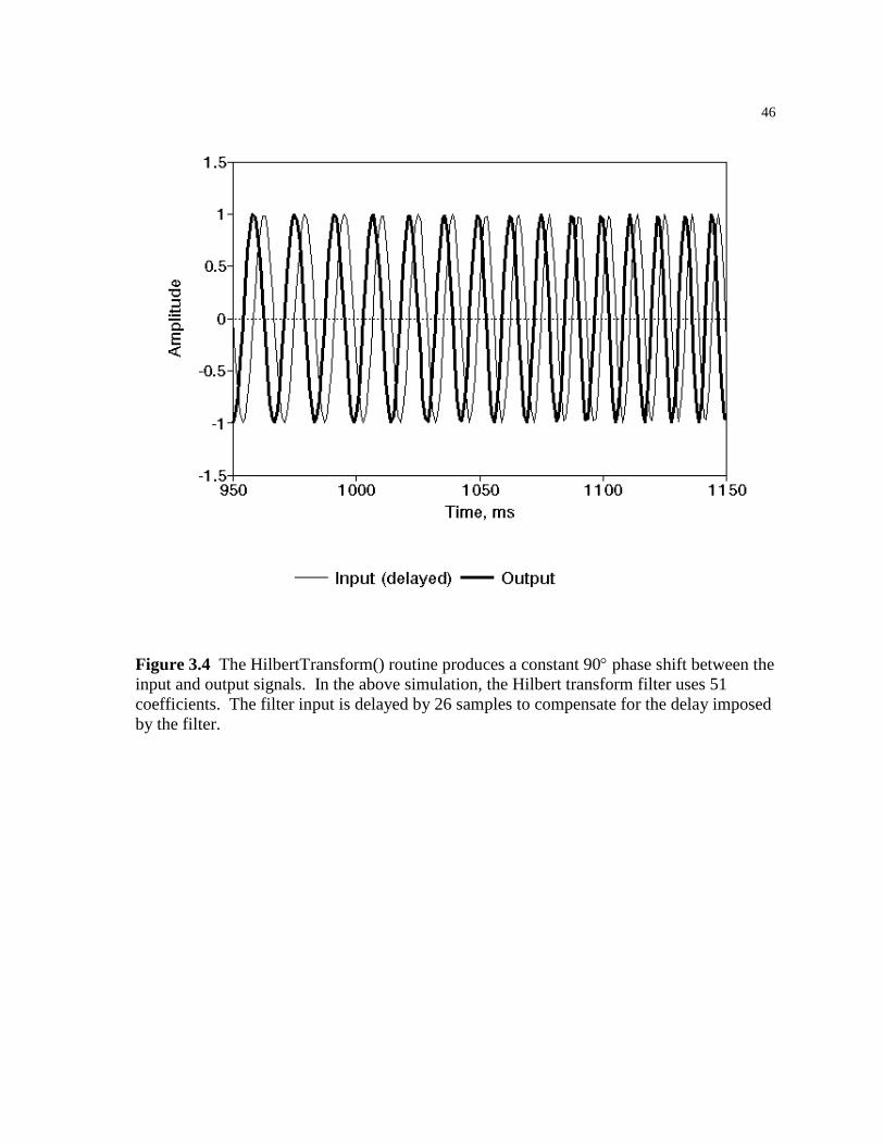
Another subroutine, HilbertTransform(), convolves the Hilbert transform
coefficients with the AGC output signal, producing a signal which is identical to uagc
but shifted by 90° and delayed by half the length of the filter. Figure 3.4 shows the
input and output of this routine when a swept sinusoid is used as the input signal.
Note that the filter input is delayed in this graph to compensate for the delay
imposed by this implementation of the Hilbert transform.
46
Figure 3.4 The HilbertTransform() routine produces a constant 90° phase shift between the input and output signals. In the above simulation, the Hilbert transform filter uses 51 coefficients. The filter input is delayed by 26 samples to compensate for the delay imposed by the filter.

47
/* * void HilbertTransform(double *input_addr, int input_length * ,int input_first_ptr, double *output_addr, int output_length * ,int output_first_ptr, double *hilbert) * * Using the hilbert[] array (initialized by FillHilbert()) * this filter convolves the most recent value of input[] with the taps * contained in hilbert[] and pushes a new output value into the signal * addressed by output_addr. * * Note that both input_addr and output_addr must be circular queues. * * This routine returns the updated output_first_ptr which is modified * by PushQueue(). */ int HilbertTransform(double *input_addr, int input_length, int input_first_ptr ,double *output_addr, int output_length, int output_first_ptr ,double *hilbert) int j; /* counter */ double out; /* temp storage of result */ out=0.0; for (j=0;j<HILBERT_LENGTH;j++) /* do one convolution to create new value*/ out+=ReadQueue(input_addr,input_length,input_first_ptr,j) * hilbert[HILBERT_LENGTH-1-j]; output_first_ptr=PushQueue(output_addr,output_length,output_first_ptr,out); return(output_first_ptr);
Figure 3.5 The HilbertTransform() routine convolves the array of coefficients created by FillHilbert() with the specified input signal, producing an output signal with a 90° phase shift.
3.1.1 A more efficient approach
The preceding idea was implemented and tested before work was begun on the
adaptive algorithm. The adaptive algorithm resulted in the creation of the
CosineVCO() subroutine, which was presented in chapter 1. This subroutine creates
a second VCO output signal which is 90° out of phase with the uvco signal. This
suggests a simpler approach to lock detection. Instead of applying a Hilbert
transform to the AGC output signal, the output of CosineVCO() may be multiplied
with the uagc signal to produce a similar result. This method is computationally
efficient, saving the time required by the convolution in HilbertTransform(). While
48
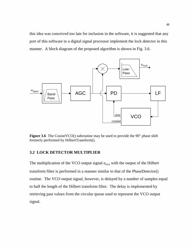
this idea was conceived too late for inclusion in the software, it is suggested that any
port of this software to a digital signal processor implement the lock detector in this
manner. A block diagram of the proposed algorithm is shown in Fig. 3.6.
PD LF
VCO
Band-Pass
AGC
Low-Pass
u
uinput
lock
cosine
sine
Figure 3.6 The CosineVCO() subroutine may be used to provide the 90° phase shift formerly performed by HilbertTransform().
3.2 LOCK DETECTOR MULTIPLIER
The multiplication of the VCO output signal uvco with the output of the Hilbert
transform filter is performed in a manner similar to that of the PhaseDetector()
routine. The VCO output signal, however, is delayed by a number of samples equal
to half the length of the Hilbert transform filter. The delay is implemented by
retrieving past values from the circular queue used to represent the VCO output
signal.

49
/* * int LockDetectorMultiplier(double *input_shifted * ,int input_shifted_length, int input_shifted_ptr * ,double *vco_output, int vco_output_length, int vco_output_ptr * ,double *output, int output_length, int output_ptr); * * After the filtered input signal has been shifted by 90 degrees (by * the Hilbert transform), this routine multiplies this shifted and filtered * input signal with the output of the VCO (which must be delayed to account * for the Hilbert transform -- center point of Hilbert taps is given by * ((HILBERT_LENGTH+1)/2). The result is placed in the output circular * queue and the current pointer (returned by PushQueue()) is returned. * * If the PLL has locked, the average value of the output signal should * be positive. Otherwise the two input signals should be uncorrelated * and the average value should be zero. */ int LockDetectorMultiplier(double *input_shifted ,int input_shifted_length, int input_shifted_ptr ,double *vco_output, int vco_output_length, int vco_output_ptr ,double *output, int output_length, int output_ptr) double last_fil,last_vco; last_fil=ReadQueue(input_shifted, input_shifted_length , input_shifted_ptr, 0); last_vco=ReadQueue(vco_output, vco_output_length, vco_output_ptr , ((HILBERT_LENGTH+1)/2)); return(PushQueue(output, output_length, output_ptr, last_fil*last_vco));
Figure 3.7 The LockDetectorMultiplier() multiplies the phase-shifted input signal with a delayed version of the VCO output signal.
3.3 VARIABLE LENGTH AVERAGING FILTER
The output of the lock detector multiplier has a positive average value while the PLL
is locked and an average value of zero while the PLL is unlocked. A low-pass filter
must be used to calculate the average value of this signal before it can be used in
lock detection. A fixed-length averaging filter may perform this function
adequately, but the frequency response would be fixed as well, while the operating
frequency of the PLL may vary. To provide a frequency response which is relative
to the operating frequency of the PLL, a variable-length averaging filter is used.
This filter averages the output of the lock detector multiplier over a fixed number of
periods of the VCO center frequency. (The adaptive algorithm presented in chapter
50
5 adjusts the VCO center frequency to match that of the input signal.) The output of
the variable-length averaging filter ulock is then consistent across all operating
frequencies of the PLL.
A filter length of ten periods of ωo was empirically chosen as a compromise
between the response time of the filter and the amount of AC superimposed upon
ulock. The AveragingFilter() subroutine continually adjusts the length of the filter to
compensate for any change in ωo. Typical input and output signals of the lock
detector averaging filter are shown in Fig. 3.8, in which an input sinusoid is swept
through the lock range of the PLL. It can be seen that the use of the averaging filter
allows the use of a threshold to determine whether the PLL is locked or not. A
threshold of zero was selected since the average only falls below zero when the PLL
is unlocked.
Recall from chapter 1 that the phase difference between the input signal and
the VCO output signal is only 90° when the input frequency is identical to that of the
VCO center frequency. As a result, the lock detector output reaches a maximum at
this point and gradually decreases as the input signal frequency deviates from the
center frequency of the VCO, until it drops abruptly to zero when the PLL unlocks.

51
Figure 3.8 The input signal to a PLL with ωo = 93.75 Hz is swept from 65 Hz to 125 Hz. The input signal to the averaging filter is shown in black, with the filter output superimposed in white.
52
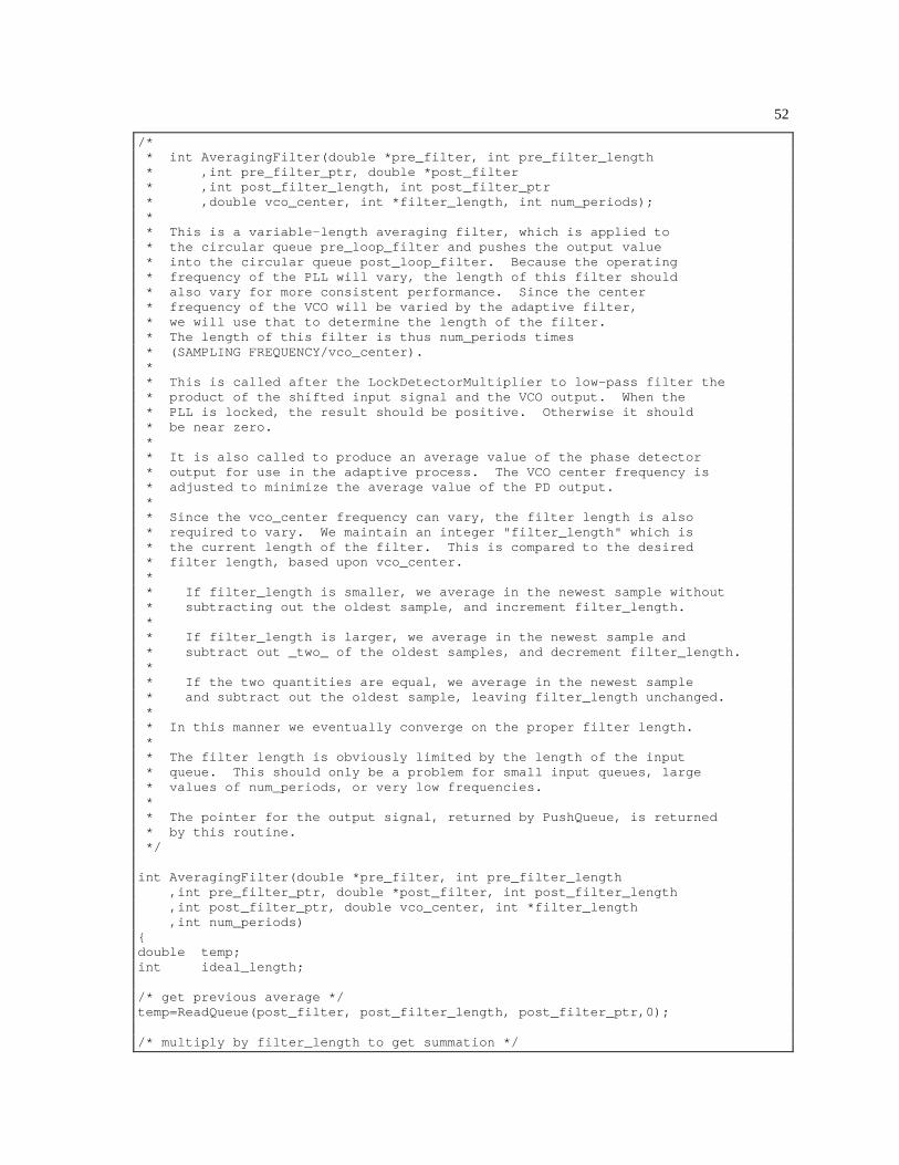
/* * int AveragingFilter(double *pre_filter, int pre_filter_length * ,int pre_filter_ptr, double *post_filter * ,int post_filter_length, int post_filter_ptr * ,double vco_center, int *filter_length, int num_periods); * * This is a variable-length averaging filter, which is applied to * the circular queue pre_loop_filter and pushes the output value * into the circular queue post_loop_filter. Because the operating * frequency of the PLL will vary, the length of this filter should * also vary for more consistent performance. Since the center * frequency of the VCO will be varied by the adaptive filter, * we will use that to determine the length of the filter. * The length of this filter is thus num_periods times * (SAMPLING FREQUENCY/vco_center). * * This is called after the LockDetectorMultiplier to low-pass filter the * product of the shifted input signal and the VCO output. When the * PLL is locked, the result should be positive. Otherwise it should * be near zero. * * It is also called to produce an average value of the phase detector * output for use in the adaptive process. The VCO center frequency is * adjusted to minimize the average value of the PD output. * * Since the vco_center frequency can vary, the filter length is also * required to vary. We maintain an integer "filter_length" which is * the current length of the filter. This is compared to the desired * filter length, based upon vco_center. * * If filter_length is smaller, we average in the newest sample without * subtracting out the oldest sample, and increment filter_length. * * If filter_length is larger, we average in the newest sample and * subtract out _two_ of the oldest samples, and decrement filter_length. * * If the two quantities are equal, we average in the newest sample * and subtract out the oldest sample, leaving filter_length unchanged. * * In this manner we eventually converge on the proper filter length. * * The filter length is obviously limited by the length of the input * queue. This should only be a problem for small input queues, large * values of num_periods, or very low frequencies. * * The pointer for the output signal, returned by PushQueue, is returned * by this routine. */ int AveragingFilter(double *pre_filter, int pre_filter_length ,int pre_filter_ptr, double *post_filter, int post_filter_length ,int post_filter_ptr, double vco_center, int *filter_length ,int num_periods) double temp; int ideal_length; /* get previous average */ temp=ReadQueue(post_filter, post_filter_length, post_filter_ptr,0); /* multiply by filter_length to get summation */
53
temp *= (*filter_length); /* add most recent point to summation */ temp += ReadQueue(pre_filter, pre_filter_length, pre_filter_ptr,0); /* calculate ideal filter length */ ideal_length=(int)(num_periods*(double)SAMPLING_FREQUENCY /vco_center*TWO_PI); /* if filter is the ideal length, or if filter is less than the ideal * length but can't get any larger due to the size of the input signal * queue, we leave the size unchanged. */ if (((*filter_length) == ideal_length) /* filter is "just right" */ || ( ((*filter_length)<ideal_length) && ((*filter_length)==pre_filter_length) ) ) /* at maximum length */ /* subtract oldest point */ temp -= ReadQueue(pre_filter, pre_filter_length , pre_filter_ptr,(*filter_length)-1); /* oldest point */ else if ((*filter_length) > ideal_length) /* filter is too big */ /* subtract out two oldest points */ temp -= ReadQueue(pre_filter, pre_filter_length , pre_filter_ptr,(*filter_length)-1); /* oldest point */ temp -= ReadQueue(pre_filter, pre_filter_length , pre_filter_ptr,(*filter_length)-2); /* 2nd oldest point */ (*filter_length)--; /* decrement filter_length */ else /* too small - subtract out no points, increment filter_length */ if ((*filter_length) < ideal_length) (*filter_length)++; if (*filter_length) /* must be nonzero */ temp /= (double)(*filter_length); return(PushQueue(post_filter, post_filter_length,post_filter_ptr,temp));
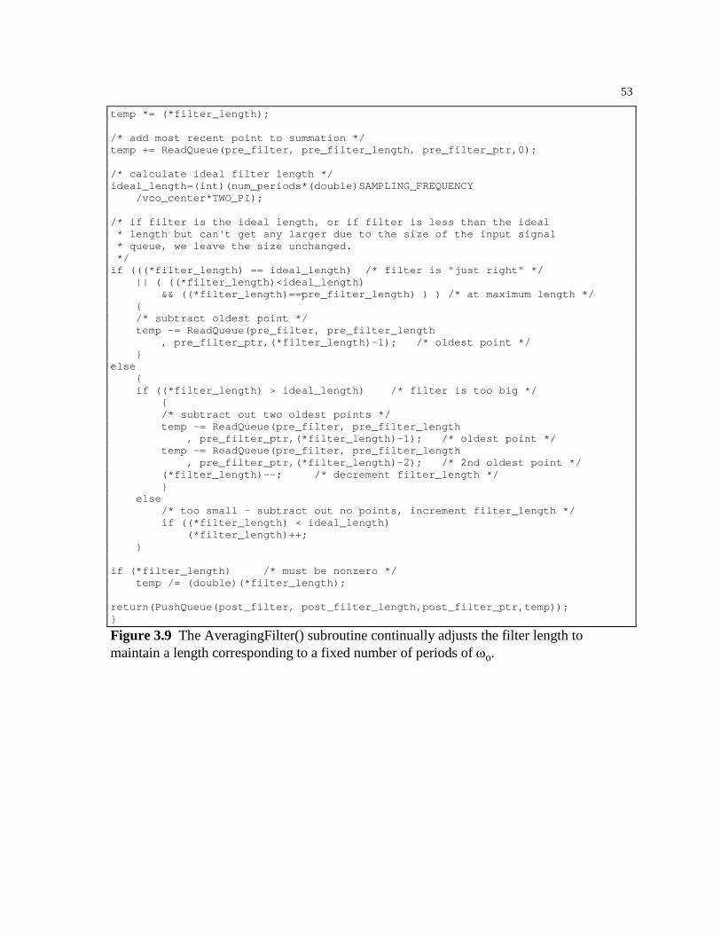
Figure 3.9 The AveragingFilter() subroutine continually adjusts the filter length to maintain a length corresponding to a fixed number of periods of ωo.

54
4 The Automated Selection of PLL Parameters
The preceding chapters show the modules necessary to implement a software phase-
locked loop. However, a significant number of parameters must be set for proper
operation of the PLL. These parameters depend upon the frequency of the input
signal and the corresponding signal-to-noise ratio. The Supervisor() algorithm has
been developed to automate the selection of these parameters. The result is a PLL
that can be placed in an arbitrary environment and will configure itself to lock onto
the largest sinusoid in the input signal. Should the input signal change significantly,
causing the PLL to unlock, the Supervisor() algorithm is called to quickly reestablish
a lock. While this does not produce a truly adaptive phase-locked loop, the time
spent in the unlocked state is quite small [7] and the phase-locked loop does not
require any operator intervention to reconfigure itself to the changed signal.
4.1 OVERVIEW OF THE SUPERVISOR ALGORITHM
The Supervisor() subroutine is called to provide the initial operating parameters and
to rescue an unlocked PLL when the output of the lock detector falls below zero.
The algorithm begins by using a low-resolution FFT to obtain the power spectrum of
the input signal. The peak of the power spectrum is assumed to be caused by a
sinusoid, so the VCO center frequency ωo is set to the center of the frequency band
represented by this peak. Since the frequency of this sinusoid may fall anywhere in
this band, the loop filter coefficients are calculated to provide a lock range that
55
overlaps this frequency band. The width of this frequency band is inversely
proportional to the length of the FFT used to obtain the power spectrum. With the
largest sinusoid assumed to fall within a known range of frequencies, the input
signal bandpass filter is configured to attenuate noise and signals that fall outside
this range.
After the PLL has been configured using a given FFT length to set the loop
parameters, the power spectrum and loop parameters are used to calculate an
estimate of the signal-to-noise ratio that will be found in the loop for a PLL
operating under these conditions. If this SNR is below a set threshold, the length of
the FFT is doubled and the configuration process is repeated. This decreases both
the lock range and the bandwidth of the bandpass filter, improving the noise
immunity of the PLL. The configuration process repeats until the estimated SNR
rises above a set threshold or the desired FFT length exceeds the length of the input
buffer.
While the FFT length could be initially set to a very large value to provide a
very high SNR and eliminate the need for the iterative process, there are two
advantages to the use of the iterative approach. In the first iteration, the lock range
is large, and is only decreased in successive iterations if required by the presence of
noise. This maximizes the tracking ability of the PLL for a given amount of noise.
Furthermore, beginning with a low-resolution FFT greatly reduces the amount of
time required to calculate the PLL parameters for a system with low to moderate
amounts of noise.
An initial power spectrum length of 33 points was selected to provide a large
lock range for input signals with minimal amounts of noise. The upper limit on the
power spectrum length is set by the length of the circular buffer representing the
56
input signal. In simulations, this buffer contained 1024 words which set the upper
limit on the power spectrum length to 513 points.
When the final operating parameters for the phase-locked loop have been
selected, the Supervisor() subroutine initializes two other PLL components that were
added to improve the noise immunity of the PLL. The AGC() subroutine, presented
in chapter 2, performs an incremental DC average over the length of the input signal
buffer. The average value is increased by a fraction of the most recent data sample
and decreased by a fraction of the oldest data sample:
Avg t Avg tu t u t L
Linput input( ) ( )
( ) ( )= − +
− − −1
1
where L is the length of the input signal buffer. For this form of averaging to work
properly, the value Avg t( ) must be initialized to the average value of the samples in
this buffer.
In chapter 5, an adaptive noise canceler [10] is added to the input signal
conditioning in an attempt to further reduce the susceptibility of the PLL to noise.
The block diagram of this noise canceler is shown in Fig. 4.1. The delay stage is
initialized by the Supervisor() subroutine to be three periods of the VCO center
frequency ωo. This delay is sufficient to decorrelate the broadband signal
components from the period components and provide a useful error signal for the
noise canceler. The noise canceler was disabled for all simulations in this chapter to
prevent it from changing the SNR of the input signal.

57
Delay AdaptiveFilter
-
uinput
to bandpassfilter
Figure 4.1 An adaptive noise canceler is placed in series with the input signal to attenuate uncorrelated noise components.
After Supervisor() has configured the PLL, the software operates for 4000
iterations before the output of the lock detector is used to determine if the PLL has
unlocked and another call to Supervisor() is required. This value was chosen
empirically by observing the output of the lock detector with different input signals
to determine a ceiling for the amount of time the PLL requires to lock. Figures 4.2
through 4.5 show the resulting PLL parameters and lock detector output for a PLL
initialized by Supervisor() with input signals of varying signal-to-noise ratio. The
lock time is illustrated in Fig. 4.6 with a superposition of lock detector output signals
for several input signals of varying SNR. A flowchart for the Supervisor()
subroutine is shown in Fig. 4.7.

58
Entering the Supervisor routine... Iterative process: power spectrum length = 33 points Peak frequency at 46.875000 +/- 7.812500 Hz Pseudo-SNR of input signal: 15146.146893 Pseudo-SNR in phase-locked loop: 20192.829166 Exiting Supervisor routine with the following conditions: Pseudo-SNR of input signal: 15146.146893 Upper corner frequency of bandpass filter: 54.687500 Hz Lower corner frequency of bandpass filter: 39.062500 Hz Input noise bandwidth: 15.625000 Hz PLL noise bandwidth: 5.859965 Hz Pseudo-SNR in phase-locked loop: 20192.829166 PLL natural resonant frequency: 11.050212 Hz PLL damping constant (fixed): 0.707000 VCO center frequency: 46.875000 Hz PLL lock range: 15.625000 Hz PLL loop gain: 196.349541 PLL loop filter time constants: tau1 = 0.025459, tau2 = 0.015273
Figure 4.2 The text output of the Supervisor() subroutine and the resulting lock detector output are shown for a noiseless 50 Hz input signal sampled at 1 KHz.

59
Entering the Supervisor routine... Iterative process: power spectrum length = 33 points Peak frequency at 46.875000 +/- 7.812500 Hz Pseudo-SNR of input signal: 5.734038 Pseudo-SNR in phase-locked loop: 7.644614 Iterative process: power spectrum length = 65 points Peak frequency at 46.875000 +/- 3.906250 Hz Pseudo-SNR of input signal: 9.105582 Pseudo-SNR in phase-locked loop: 12.139553 Iterative process: power spectrum length = 129 points Peak frequency at 50.781250 +/- 1.953125 Hz Pseudo-SNR of input signal: 20.656668 Pseudo-SNR in phase-locked loop: 27.539451 Exiting Supervisor routine with the following conditions: Pseudo-SNR of input signal: 20.656668 Upper corner frequency of bandpass filter: 52.734375 Hz Lower corner frequency of bandpass filter: 48.828125 Hz Input noise bandwidth: 3.906250 Hz PLL noise bandwidth: 1.464991 Hz Pseudo-SNR in phase-locked loop: 27.539451 PLL natural resonant frequency: 2.762553 Hz PLL damping constant (fixed): 0.707000 VCO center frequency: 50.781250 Hz PLL lock range: 3.906250 Hz PLL loop gain: 49.087385 PLL loop filter time constants: tau1 = 0.101835, tau2 = 0.061091
Figure 4.3 The text output of the Supervisor() subroutine and the resulting lock detector output are shown for a 50 Hz input signal sampled at 1 KHz with a signal-to-noise ratio of 0.39. Three iterations of the Supervisor() routine are required to sufficiently reduce the noise in the PLL.
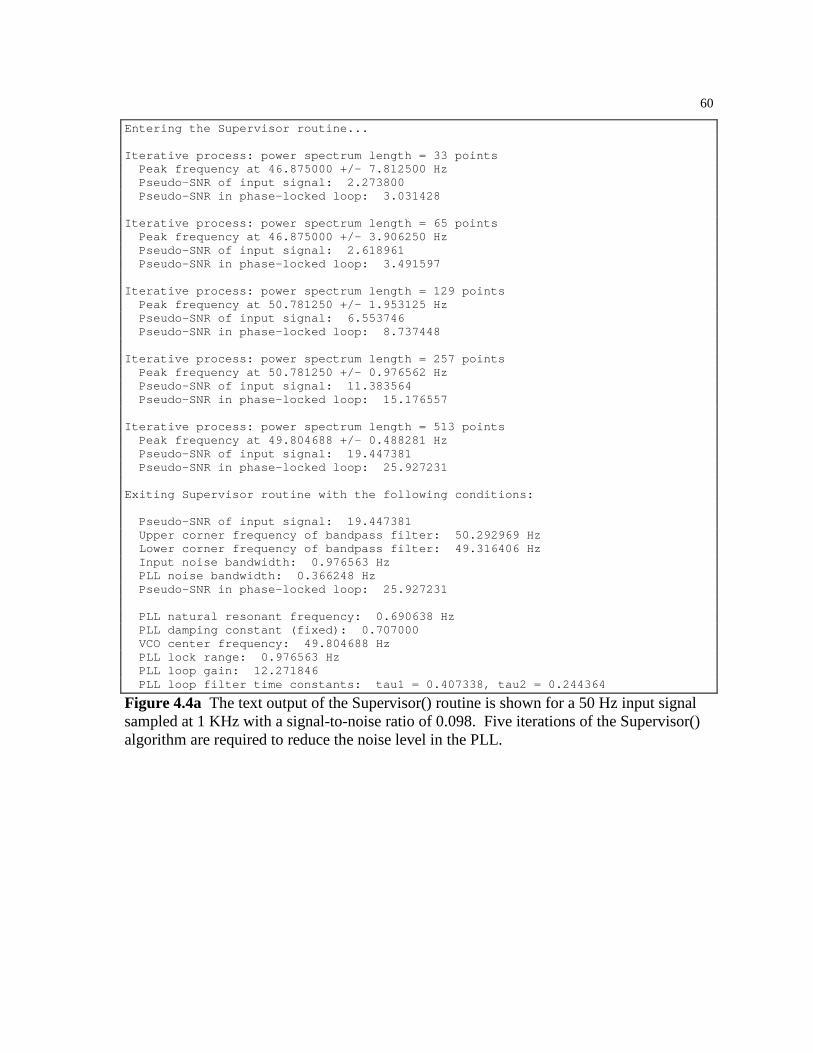
60
Entering the Supervisor routine... Iterative process: power spectrum length = 33 points Peak frequency at 46.875000 +/- 7.812500 Hz Pseudo-SNR of input signal: 2.273800 Pseudo-SNR in phase-locked loop: 3.031428 Iterative process: power spectrum length = 65 points Peak frequency at 46.875000 +/- 3.906250 Hz Pseudo-SNR of input signal: 2.618961 Pseudo-SNR in phase-locked loop: 3.491597 Iterative process: power spectrum length = 129 points Peak frequency at 50.781250 +/- 1.953125 Hz Pseudo-SNR of input signal: 6.553746 Pseudo-SNR in phase-locked loop: 8.737448 Iterative process: power spectrum length = 257 points Peak frequency at 50.781250 +/- 0.976562 Hz Pseudo-SNR of input signal: 11.383564 Pseudo-SNR in phase-locked loop: 15.176557 Iterative process: power spectrum length = 513 points Peak frequency at 49.804688 +/- 0.488281 Hz Pseudo-SNR of input signal: 19.447381 Pseudo-SNR in phase-locked loop: 25.927231 Exiting Supervisor routine with the following conditions: Pseudo-SNR of input signal: 19.447381 Upper corner frequency of bandpass filter: 50.292969 Hz Lower corner frequency of bandpass filter: 49.316406 Hz Input noise bandwidth: 0.976563 Hz PLL noise bandwidth: 0.366248 Hz Pseudo-SNR in phase-locked loop: 25.927231 PLL natural resonant frequency: 0.690638 Hz PLL damping constant (fixed): 0.707000 VCO center frequency: 49.804688 Hz PLL lock range: 0.976563 Hz PLL loop gain: 12.271846 PLL loop filter time constants: tau1 = 0.407338, tau2 = 0.244364
Figure 4.4a The text output of the Supervisor() routine is shown for a 50 Hz input signal sampled at 1 KHz with a signal-to-noise ratio of 0.098. Five iterations of the Supervisor() algorithm are required to reduce the noise level in the PLL.

61
Figure 4.4b The lock detector output is shown for the conditions of Fig. 4.4a. The amount of time required for the PLL to lock increases as the signal-to-noise ratio decreases.

62
Entering the Supervisor routine... Iterative process: power spectrum length = 33 points Peak frequency at 453.125000 +/- 7.812500 Hz Pseudo-SNR of input signal: 2.350839 Pseudo-SNR in phase-locked loop: 3.134137 Iterative process: power spectrum length = 65 points Peak frequency at 445.312500 +/- 3.906250 Hz Pseudo-SNR of input signal: 2.653222 Pseudo-SNR in phase-locked loop: 3.537273 Iterative process: power spectrum length = 129 points Peak frequency at 50.781250 +/- 1.953125 Hz Pseudo-SNR of input signal: 3.713420 Pseudo-SNR in phase-locked loop: 4.950729 Iterative process: power spectrum length = 257 points Peak frequency at 50.781250 +/- 0.976562 Hz Pseudo-SNR of input signal: 6.004303 Pseudo-SNR in phase-locked loop: 8.004931 Iterative process: power spectrum length = 513 points Peak frequency at 49.804688 +/- 0.488281 Hz Pseudo-SNR of input signal: 9.755029 Pseudo-SNR in phase-locked loop: 13.005396 Supervisor(): reached maximum spectrum length. Returning with most recent filter coefficients. Lock is possible but not likely. Exiting Supervisor routine with the following conditions: Pseudo-SNR of input signal: 9.755029 Upper corner frequency of bandpass filter: 50.292969 Hz Lower corner frequency of bandpass filter: 49.316406 Hz Input noise bandwidth: 0.976563 Hz PLL noise bandwidth: 0.366248 Hz Pseudo-SNR in phase-locked loop: 13.005396 PLL natural resonant frequency: 0.690638 Hz PLL damping constant (fixed): 0.707000 VCO center frequency: 49.804688 Hz PLL lock range: 0.976563 Hz PLL loop gain: 12.271846 PLL loop filter time constants: tau1 = 0.407338, tau2 = 0.244364
Figure 4.5a The text output of the Supervisor() routine is shown for a 50 Hz input signal sampled at 1 KHz with a signal-to-noise ratio of 0.044. The noise level is high enough to exhaust the memory allocated for the input signal, so the Supervisor() routine attempts to lock using the power spectrum with the best possible resolution. In fact, the 50 Hz sinusoid is not correctly identified until the third iteration.

63
Figure 4.5b The lock detector output is shown for the conditions of Fig. 4.5a. While the Supervisor() would have performed additional iterations if the input buffer had been longer, the PLL successfully locks onto the input signal. It is likely that this particular PLL will eventually unlock due to the high noise levels.
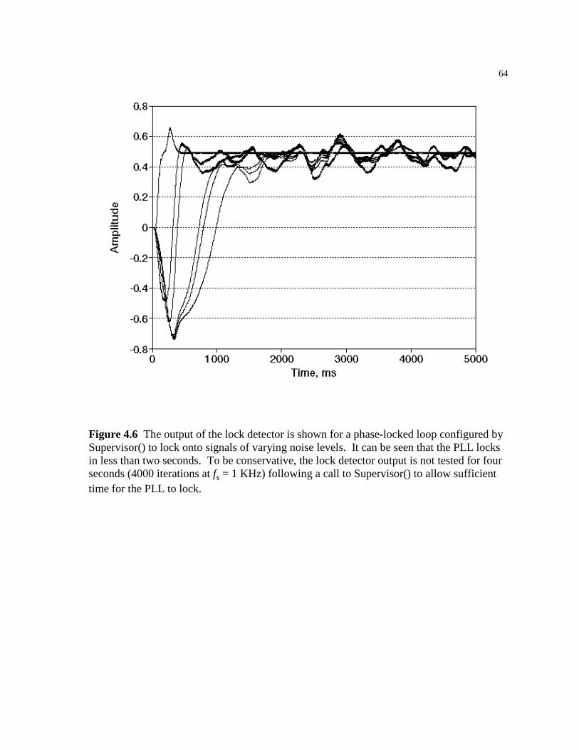
64
Figure 4.6 The output of the lock detector is shown for a phase-locked loop configured by Supervisor() to lock onto signals of varying noise levels. It can be seen that the PLL locks in less than two seconds. To be conservative, the lock detector output is not tested for four seconds (4000 iterations at fs = 1 KHz) following a call to Supervisor() to allow sufficient time for the PLL to lock.
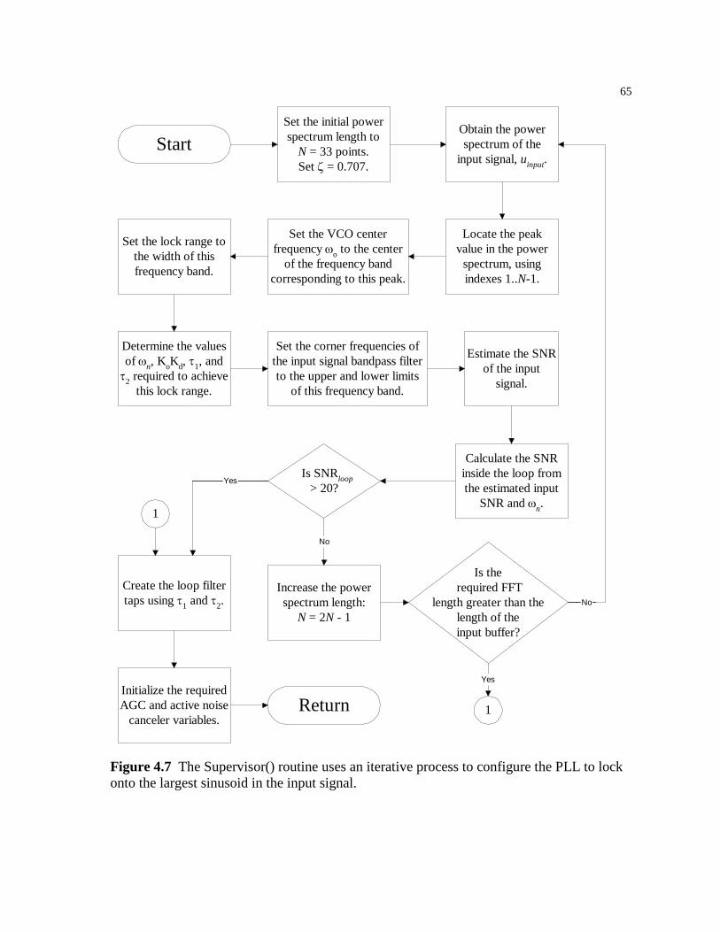
65
Figure 4.7 The Supervisor() routine uses an iterative process to configure the PLL to lock onto the largest sinusoid in the input signal.
StartSet the initial powerspectrum length to
N = 33 points.Set ζ = 0.707.
Obtain the powerspectrum of the
input signal, uinput.
Locate the peakvalue in the power
spectrum, usingindexes 1..N-1.
Set the VCO centerfrequency ωo to the center
of the frequency bandcorresponding to this peak.
Set the lock range tothe width of thisfrequency band.
Determine the valuesof ωn, KoKd, τ1, andτ2 required to achieve
this lock range.
Set the corner frequencies ofthe input signal bandpass filterto the upper and lower limits
of this frequency band.
Estimate the SNRof the input
signal.
Calculate the SNRinside the loop fromthe estimated input
SNR and ωn.
Is SNRloop> 20?
Increase the powerspectrum length:
N = 2N - 1
No
Is the required FFT
length greater than thelength of theinput buffer?
No
Create the loop filtertaps using τ1 and τ2.
Yes
1
Yes
1Initialize the requiredAGC and active noise
canceler variables.Return

66
4.2 THE POWER SPECTRUM
An existing Fast Fourier Transform routine [8] was used as part of the
PowerSpectrum() subroutine, which fills an array with a specified number of points
that represent an estimate of the power spectrum of the input signal. A periodogram
estimate for the power spectrum is defined as [9]:
PM
C( ) ( )0 1 022=
( )2
0for )()(1)( 222
MkkMCkCM
kP <<−+=
2
2 21
2
=
MC
MMP
where C is the output of an FFT of length M. This produces a power spectrum with
N M= +( / )2 1 data points representing frequencies between 0 and f s / 2 Hz. Since
the FFT requires the length M to be a power of 2, the power spectrum length must be
one greater than a power of two. A Hamming window is applied to the input signal
before the FFT is calculated as a compromise between the reduction of the
magnitude of the sidelobes and the accuracy of the main lobe amplitude. Two
power spectrums calculated by this routine are shown in Fig. 4.8.
The Supervisor() subroutine does not use the P(0) value when it examines the
power spectrum to determine the frequency of the largest sinusoid. This prevents a
DC component of the input signal from affecting the operation of Supervisor(). If
very low frequencies will be present in the target system, the initial length N of the
power spectrum should be increased such that frequencies below ( / )πf Ns 2 may be
safely ignored.
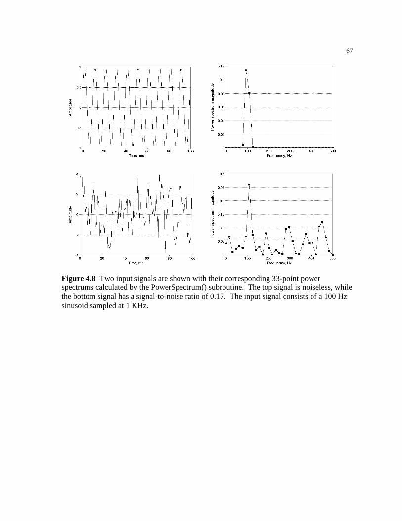
67
Figure 4.8 Two input signals are shown with their corresponding 33-point power spectrums calculated by the PowerSpectrum() subroutine. The top signal is noiseless, while the bottom signal has a signal-to-noise ratio of 0.17. The input signal consists of a 100 Hz sinusoid sampled at 1 KHz.

68
/* * void PowerSpectrum(double *input_addr, int input_length, int input_first_ptr * , double *output_spectrum, int power_length); * * Given an array input_addr (and the appropriate parameters required * by ReadQueue) this will calculate the (2*(power_length-1)) point Fast * Fourier Transform and from this estimate the power spectrum, placing the * result in output_spectrum[], which is expected to hold (power_length) * values. Note that power_length is expected to be one greater than a power * of 2. * * The routine uses the most recent (2*(power_length-1)) samples in the * input buffer. * * Credit-where-credit-is-due department: FFT routine adapted from * page 54 of "DFT/FFT and Convolution Algorithms" by Burrus and Parks. * Warning: this book contains MANY errors. * * Power spectrum estimation is as follows: * * P(0) = 1/M^2 |C(0)|^2 * * P(k) = 1/M^2 (|C(k)|^2 + |C(M-k)|^2) for k=1..M/2-1 * * P(M/2) = 1/M^2 |C(M/2)|^2 * * where C() is the output of the FFT, and M is the length of the FFT. * This yields a power spectrum of length N=M/2+1. [Biomedical DSP, 1992] */ void PowerSpectrum(double *input_addr, int input_length, int input_first_ptr , double *output_spectrum, int power_length) int m,n2,k,n1,j,i,l; double e,a,c,s,xt,yt,*x,*y; /* temporarily decrement power_length to make it an even power of 2 for * convenience during the FFT calculation. (afterwards: M = 2*N) */ power_length--; /* compute m such that 2^m = fft length = 2*power_length */ m = (int)(log(power_length*2.)/log(2.) + 0.5); /* +0.5 for rounding error*/ /* create temporary arrays */ if ((x=(double *)malloc((2*power_length+1)*sizeof(double)))==NULL) fprintf(stderr,"\npll/PowerSpectrum(): error creating x\n"); exit(1); if ((y=(double *)malloc((2*power_length+1)*sizeof(double)))==NULL) fprintf(stderr,"\npll/PowerSpectrum(): error creating y\n"); exit(1); x[0]=0; y[0]=0; /* fill temporary local array with the most recent M samples */ /* and apply a Hamming window */ for (i=0;i<2*power_length;i++)

69
/* note: Burrus/Parks algorithm begins with index of 1 */ x[i+1]=ReadQueue(input_addr, input_length, input_first_ptr ,2*power_length-i-1); x[i+1] *= (0.54 + 0.46 *cos(PI*((double)i-(double)power_length+0.5)/((double)power_length))); y[i+1]=0; /* assume real signal */ n2 = 2*power_length; /* calculate FFT */ for (k=1;k<=m;k++) n1 = n2; n2 >>= 1; e = 6.283185/n1; a = 0; for (j=1;j<=n2;j++) c = cos(a); s = -1.0*sin(a); a = (double)j * e; for (i=j;i<=2*power_length;i+=n1) l = i + n2; xt = x[i] - x[l]; x[i] += x[l]; yt = y[i] - y[l]; y[i] += y[l]; x[l] = xt*c - yt*s; y[l] = xt*s + yt*c; /* unscramble the ordering of the FFT output */ j=1; n1=2*power_length-1; for (i=1;i<=n1;i++) if (i<j) xt=x[j]; x[j]=x[i]; x[i]=xt; xt=y[j]; y[j]=y[i]; y[i]=xt; k=power_length; while(k<j) j-=k; k/=2; j+=k; /* restore power_length to its original N=2^m+1 value */ power_length++;

70
/* fill output_spectrum with the power spectrum values using the periodogram * equation (see header). */ output_spectrum[0] = (x[1]*x[1] + y[1]*y[1]) / pow(2.*(double)(power_length-1),2.); for (i=1;i<power_length-1;i++) j=2*power_length-i-1; output_spectrum[i] = ((x[i+1]*x[i+1]+y[i+1]*y[i+1]) + (x[j]*x[j]+y[j]*y[j])) / pow(2.*(double)(power_length-1),2.); i=power_length; output_spectrum[i-1] = (x[i]*x[i] + y[i]*y[i]) / pow(2.*(double)(power_length-1),2.); free((void *)x); free((void *)y); return;
Figure 4.9 The PowerSpectrum() routine fills an array with an estimate of the power spectrum of the input signal. The resolution varies with the power_length parameter, which specifies the number of values in the power spectrum array.
4.3 CALCULATION OF PLL PARAMETERS
The VCO center frequency ωo is set to the center of the frequency band represented
by the peak value in the power spectrum using the expression:
ωπ
o =⋅−
f nN
s1
where n is the index corresponding to the peak value in the power spectrum and N is
the number of values in the power spectrum of the input signal.
In chapter 1, the expressions for the natural resonant frequency ωn and the
damping factor ζ were given in terms of the loop filter time constants τ1 and τ2 and
the loop filter gain KoKd. From these values, the lock range can be predicted. In
this case, the lock range is desired to be the width of the frequency band represented
by a single value in the power spectrum:
∆ωπ
L =−f
Ns1
71
The natural resonant frequency ωn may be expressed in terms of ∆ωL and ζ:
ωωζn =
∆ L2
The damping factor ζ is chosen to be 0.707 for a maximally flat response.
Recall that the hold range ∆ωH is the frequency range over which the PLL
may be statically stable and that ∆ωH = KoKd for a PLL using a passive loop filter.
To ensure that the PLL is stable over the range of interest, the hold range (and thus
the loop gain KoKd) is set to twice the lock range.
The expressions for ωn and ζ in terms of τ1, τ2, and KoKd may be rewritten to
find the loop filter time constants τ1 and τ2 in terms of the above values of ωn, ζ, and
KoKd:
τζ
ω
τω
τ
2
1 2 2
2 1= −
= −
n
n
K KK K
o d
o d
Finally, the upper and lower corner frequencies of the input signal bandpass
filter are set to the limits of the lock range using the expressions:
ω ωω
ω ωω
u
l
= +
= −
oL
oL
∆
∆2
2
4.4 ESTIMATING THE SIGNAL-TO-NOISE RATIO
The signal to noise ratio is defined in terms of the signal power and noise power. To
calculate an accurate SNR, these individual components must be available. In this
case, the Supervisor() only has access to data samples containing both signal and
noise, so this calculation is not possible. However, an estimate may be obtained
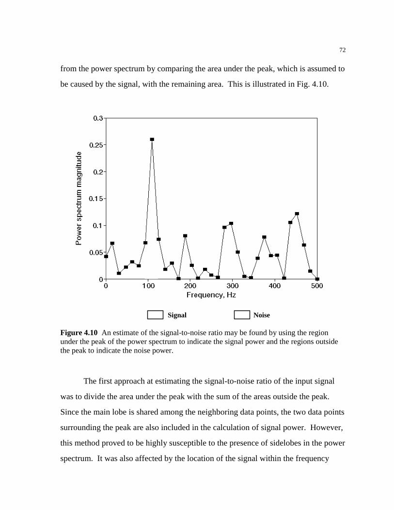
72
from the power spectrum by comparing the area under the peak, which is assumed to
be caused by the signal, with the remaining area. This is illustrated in Fig. 4.10.
Signal Noise Figure 4.10 An estimate of the signal-to-noise ratio may be found by using the region under the peak of the power spectrum to indicate the signal power and the regions outside the peak to indicate the noise power.
The first approach at estimating the signal-to-noise ratio of the input signal
was to divide the area under the peak with the sum of the areas outside the peak.
Since the main lobe is shared among the neighboring data points, the two data points
surrounding the peak are also included in the calculation of signal power. However,
this method proved to be highly susceptible to the presence of sidelobes in the power
spectrum. It was also affected by the location of the signal within the frequency

73
band represented by the peak, since the peak value was higher for a sinusoid
centered in this frequency band than for a sinusoid near the edge of this band.
Weighing the power spectrum by the expected response of the single-pole bandpass
filter on the input signal helped but did not eliminate these fundamental problems.
To overcome these problems, a simpler approach was suggested [11]. Instead
of estimating the SNR from the total signal and noise area in the power spectrum,
the average of the peak value and two neighboring points is divided by the average
of the remaining values. While this does not follow the definition of the signal-to-
noise ratio, it does provide a value that is proportional to the relative amplitudes of
the signal and noise. Furthermore, this method exhibits very little sensitivity to the
location of the signal within the frequency band represented by the power spectrum
peak. Figure 4.11 compares the actual SNR with this pseudo-SNR for different
power spectrum lengths. The estimated pseudo-SNR increases slightly as the length
of the power spectrum is increased. However, the pseudo-SNR varies little with
changes in signal frequency, as shown in Fig. 4.12.
As presented in chapter 1, the signal-to-noise ratio inside the loop is
calculated as [4]:
SNR SNRloop inputi
L
BB
=2
where the pseudo-SNR of the input signal is used for SNRinput , the input bandwidth
Bi is specified by the upper and lower corner frequencies of the input signal
bandpass filter, and the loop bandwidth BL is given by [4]:
+=
ζζ
ω41
2n
LB
To determine an appropriate threshold for SNRloop, the variance of the lock detector
output was used as a measure of lock quality. Lower signal-to-noise ratios in the
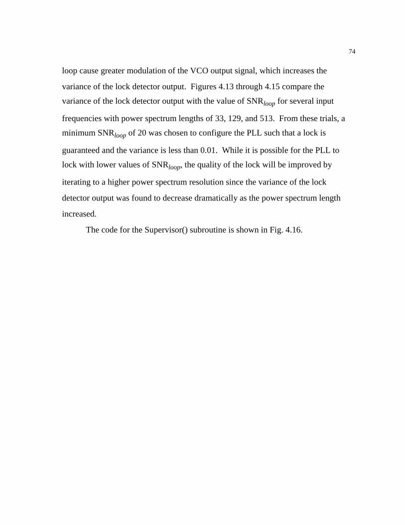
74
loop cause greater modulation of the VCO output signal, which increases the
variance of the lock detector output. Figures 4.13 through 4.15 compare the
variance of the lock detector output with the value of SNRloop for several input
frequencies with power spectrum lengths of 33, 129, and 513. From these trials, a
minimum SNRloop of 20 was chosen to configure the PLL such that a lock is
guaranteed and the variance is less than 0.01. While it is possible for the PLL to
lock with lower values of SNRloop, the quality of the lock will be improved by
iterating to a higher power spectrum resolution since the variance of the lock
detector output was found to decrease dramatically as the power spectrum length
increased.
The code for the Supervisor() subroutine is shown in Fig. 4.16.
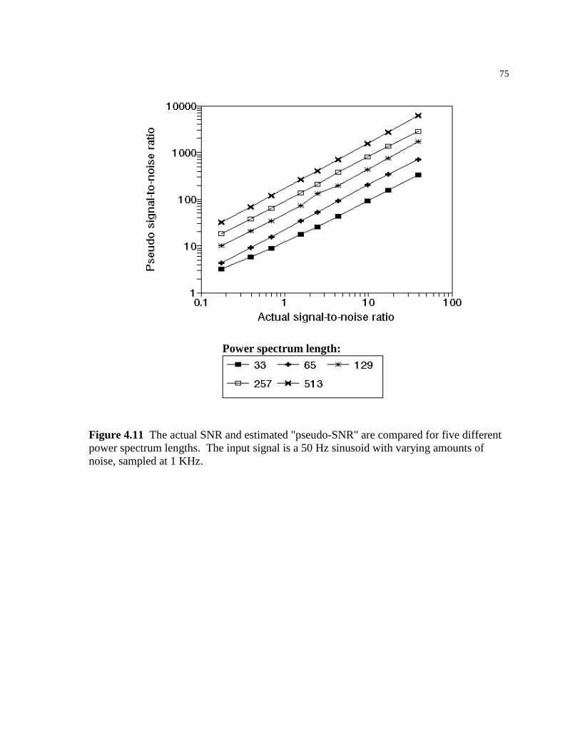
75
Power spectrum length:
Figure 4.11 The actual SNR and estimated "pseudo-SNR" are compared for five different power spectrum lengths. The input signal is a 50 Hz sinusoid with varying amounts of noise, sampled at 1 KHz.

76
Figure 4.12 The actual SNR and estimated "pseudo-SNR" are compared for input signals of varying frequency. For these simulations, the power spectrum length was set to 129 points and the sampling rate was 1 KHz.
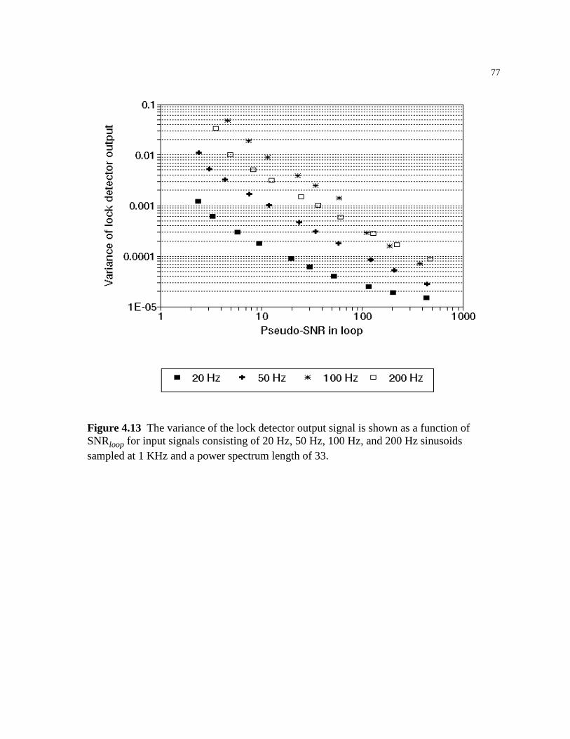
77
Figure 4.13 The variance of the lock detector output signal is shown as a function of SNRloop for input signals consisting of 20 Hz, 50 Hz, 100 Hz, and 200 Hz sinusoids sampled at 1 KHz and a power spectrum length of 33.

78
Figure 4.14 The variance of the lock detector output signal is again shown as a function of SNRloop for input signals consisting of 20 Hz, 50 Hz, 100 Hz, and 200 Hz sinusoids sampled at 1 KHz. The power spectrum length was set to 129.

79
Figure 4.15 The variance of the lock detector output signal is again shown as a function of SNRloop for input signals consisting of 20 Hz, 50 Hz, 100 Hz, and 200 Hz sinusoids sampled at 1 KHz. The power spectrum length was set to 513.
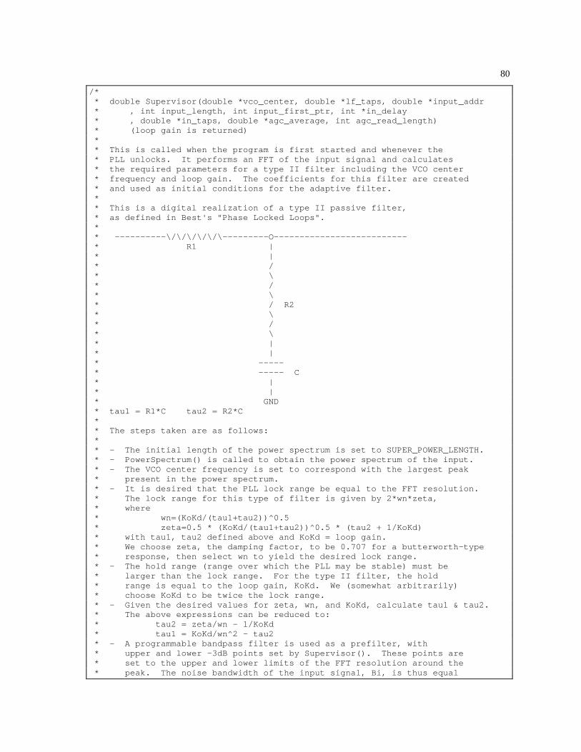
80
/* * double Supervisor(double *vco_center, double *lf_taps, double *input_addr * , int input_length, int input_first_ptr, int *in_delay * , double *in_taps, double *agc_average, int agc_read_length) * (loop gain is returned) * * This is called when the program is first started and whenever the * PLL unlocks. It performs an FFT of the input signal and calculates * the required parameters for a type II filter including the VCO center * frequency and loop gain. The coefficients for this filter are created * and used as initial conditions for the adaptive filter. * * This is a digital realization of a type II passive filter, * as defined in Best's "Phase Locked Loops". * * ----------\/\/\/\/\/\---------O-------------------------- * R1 | * | * / * \ * / * \ * / R2 * \ * / * \ * | * | * ----- * ----- C * | * | * GND * tau1 = R1*C tau2 = R2*C * * The steps taken are as follows: * * - The initial length of the power spectrum is set to SUPER_POWER_LENGTH. * - PowerSpectrum() is called to obtain the power spectrum of the input. * - The VCO center frequency is set to correspond with the largest peak * present in the power spectrum. * - It is desired that the PLL lock range be equal to the FFT resolution. * The lock range for this type of filter is given by 2*wn*zeta, * where * wn=(KoKd/(tau1+tau2))^0.5 * zeta=0.5 * (KoKd/(tau1+tau2))^0.5 * (tau2 + 1/KoKd) * with tau1, tau2 defined above and KoKd = loop gain. * We choose zeta, the damping factor, to be 0.707 for a butterworth-type * response, then select wn to yield the desired lock range. * - The hold range (range over which the PLL may be stable) must be * larger than the lock range. For the type II filter, the hold * range is equal to the loop gain, KoKd. We (somewhat arbitrarily) * choose KoKd to be twice the lock range. * - Given the desired values for zeta, wn, and KoKd, calculate tau1 & tau2. * The above expressions can be reduced to: * tau2 = zeta/wn - 1/KoKd * tau1 = KoKd/wn^2 - tau2 * - A programmable bandpass filter is used as a prefilter, with * upper and lower -3dB points set by Supervisor(). These points are * set to the upper and lower limits of the FFT resolution around the * peak. The noise bandwidth of the input signal, Bi, is thus equal

81
* to the FFT resolution. * - Look for potential noise problems. We calculate SNRin from * the power spectrum by dividing the average value of the signal peak * and neighboring bins by the average of the remaining bins (presumed * noise). The noise bandwidth of the PLL for the type II filter * is given by the expression Bl = 1/2 * wn * (zeta + 1/(4*zeta)). * - The SNR of the signal after the VCO, SNRout, = SNRin (Bi/(2*Bl)). * If this SNR is less than SUPER_SNR_THRESHOLD, the PLL may not lock * or may be subject to more noise than necessary. If this happens the * routine doubles the length of the Fourier transform and repeats this * process. This reduces the lock range, and thus wn, by a factor of 2. * However, the input bandwidth is also reduced by a factor of two * so the improvement in SNRout is entirely dependent upon the improvement * in SNRin. * * If the required FFT length becomes greater than the length of the input * queue (input_length), the routine will use the last obtained parameters. * This indicates that a large amount of noise is present and a solid lock may * or may not occur. * * The goal of the iterative approach is to maximize the lock range * and prefilter bandwidth for a given signal-to-noise ratio. As the * noise increases, more iterations are performed and the lock range * and prefilter bandwidth decrease and the SNR rises. * * The value of zeta is #defined in SUPER_ZETA. * * The SNR threshold is #defined in SUPER_SNR_THRESHOLD. * * 21-jul-93 Added initialization of in_delay and in_taps for * the adaptive noise canceler. in_taps are initialized to * the first tap 1 and remaining taps zero (no filtering). * Note that the SNR ratios are now very conservative * since the adaptive noise canceler should remove the * uncorrelated noise from the input signal. Possible * future improvement: Calculate the SNR based upon * the input signal _after_ the adaptive noise canceler. * Expected benefit: increased lock range. * 29-nov-93 Added calculation of agc_average to initialize AGC(). */ double Supervisor(double *vco_center, double *lf_taps, double *input_addr , int input_length, int input_first_ptr, double *prefilter_workspace , int *in_delay, double *in_taps, double *agc_average, int agc_read_length) /* loop gain is returned */ int power_length=SUPER_POWER_LENGTH; /* initial length of power_spectrum */ double *spectrum; /* filled by PowerSpectrum */ int i; int exit_flag; /* for the do-while loop */ int peak_index; /* index of peak value in power spectrum */ double peak; /* peak value in power spectrum */ double lock_range; /* desired lock range of PLL */ double wn; /* natural resonant frequency of filter */ double tau1,tau2; /* filter coefficients */ double signal,noise; /* for calculation of SNRin */ int noise_n; /* for calc. of SNRin -- number of noise points */ double snr_in; /* SNR of input signal */ double b_i; /* input noise bandwidth */ double b_l; /* PLL noise bandwidth */ double snr_out; /* SNR of signal at VCO output */
82
double wu,wl; /* upper, lower -3dB freqs for bandpass prefilter */ double loop_gain; /* loop gain applied to output of loop filter */ printf("Entering the Supervisor routine...\n"); exit_flag=0; /* clear prior output values of prefilter (IIR) */ prefilter_workspace[2]=0; prefilter_workspace[3]=0; do /* repeat process until predicted SNR of loop is > threshold */ printf("\nIterative process: power spectrum length = %d points\n" ,power_length); /* allocate space for spectrum[] */ if ((spectrum=(double *)malloc(power_length*sizeof(double)))==NULL) fprintf(stderr,"\npll/Supervisor(): error creating spectrum queue\n"); exit(1); PowerSpectrum(input_addr, input_length, input_first_ptr , spectrum, power_length); /* find largest component in PowerSpectrum, besides DC */ peak_index=0; peak= -1.E308; /* very low value */ for (i=1;i<power_length;i++) if (spectrum[i]>peak) peak=spectrum[i]; peak_index=i; /* set vco center frequency to the frequency corresponding to * the peak value in the power spectrum. */ (*vco_center) = (double)SAMPLING_FREQUENCY/(double)((power_length-1)*2) *((double)peak_index); printf(" Peak frequency at %f ",(*vco_center)); (*vco_center) *= TWO_PI; /* convert from Hz to radians/sec */ /* calculate lock_range, which is equal to the resolution of the FFT. * The FFT resolution is SAMPLING_FREQUENCY/(2*(power_length-1)) Hz. */ lock_range = (double)SAMPLING_FREQUENCY/(double)(2.*(power_length-1)); printf("+/- %f Hz\n",lock_range/2.); lock_range *= TWO_PI; /* convert from Hz to radians/sec */ /* calculate Wn (natural resonant freq of filter) */ wn = lock_range / (2.0 * SUPER_ZETA); /* set the loop gain (=hold range) to twice the lock range */ loop_gain = 2.*lock_range; /* calculate tau1, tau2 */ tau2= 2.*SUPER_ZETA/wn - 1./loop_gain; tau1= loop_gain/pow(wn,2.) - tau2; /* set upper, lower -3dB points for bandpass "prefilter" */

83
wu = (*vco_center) + lock_range/2.; wl = (*vco_center) - lock_range/2.; /* set bandpass filter coefficients */ prefilter_workspace[0] = 1/tan((wu-wl)/(2.*SAMPLING_FREQUENCY)); prefilter_workspace[1] = 2.*cos( sqrt(wu*wl) / SAMPLING_FREQUENCY); /* calculate signal & noise power by averaging the power spectrum values * within one point of the peak (signal) and elsewhere (noise). */ noise=0; noise_n=0; signal=0; for (i=0;i<power_length;i++) if (i < peak_index-1) noise += spectrum[i]; noise_n++; else if (i > peak_index+1) noise += spectrum[i]; noise_n++; else /* within one point of peak */ signal += spectrum[i]; noise /= (double)noise_n; /* average value of noise */ signal /= 3.; /* average of peak & neighbors */ if (noise > 1E-10) snr_in = signal/noise; else snr_in = 1E10; /* no noise == really big SNR */ printf(" Pseudo-SNR of input signal: %f\n",snr_in); /* free the spectrum queue since it is no longer needed */ free ((void *)spectrum); /* calculate input noise bandwidth from -3dB points of filter */ b_i = wu - wl; /* calculate noise bandwidth of PLL */ /* b_l = 0.5 * wn (zeta + 1/(4zeta)). */ /* note: if zeta is fixed at 0.707, b_l = 0.53 wn */ b_l = 0.5 * wn * (SUPER_ZETA + 1./(4.*SUPER_ZETA)); /* calculate SNRout */ snr_out = snr_in * b_i / (2. * b_l); printf(" Pseudo-SNR in phase-locked loop: %f\n",snr_out); /* if SNRout is > threshold or the next iteration requires more samples than * are present in the input_queue, leave this loop. */ /* First, increase the length of the power spectrum, from 1+2^N to * 1+2^(N+1) */ power_length = 2*power_length-1;
84
if (snr_out > SUPER_SNR_THRESHOLD) /* Is SNR above threshold? */ exit_flag++; else /* fft length =2*(power_length-1) */ if (2*(power_length-1) > input_length) fprintf(stderr,"Supervisor(): reached maximum spectrum length.\n"); fprintf(stderr, " Returning with most recent filter coefficients.\n"); fprintf(stderr, " Lock is possible but not likely.\n"); exit_flag++; while (!exit_flag); printf("\nExiting Supervisor routine with the following conditions:\n\n"); printf(" Pseudo-SNR of input signal: %f\n",snr_in); printf(" Upper corner frequency of bandpass filter: %f Hz\n",wu/(TWO_PI)); printf(" Lower corner frequency of bandpass filter: %f Hz\n",wl/(TWO_PI)); printf(" Input noise bandwidth: %f Hz\n",b_i/(TWO_PI)); printf(" PLL noise bandwidth: %f Hz\n",b_l/(TWO_PI)); printf(" Pseudo-SNR in phase-locked loop: %f\n",snr_out); printf("\n PLL natural resonant frequency: %f Hz\n",wn/(TWO_PI)); printf(" PLL damping constant (fixed): %f\n",SUPER_ZETA); printf(" VCO center frequency: %f Hz\n",(*vco_center)/(TWO_PI)); printf(" PLL lock range: %f Hz\n",lock_range/(TWO_PI)); printf(" PLL loop gain: %f\n",loop_gain); printf(" PLL loop filter time constants: tau1 = %f, tau2 = %f\n\n",tau1,tau2); CreateFilterTaps(tau1,tau2,lf_taps); /* create filter */ /* set delay length for adaptive noise canceler and initialize the taps */ (*in_delay) = (int)(IN_DELAY_NUM_PERIODS*(double)SAMPLING_FREQUENCY /(*vco_center)*TWO_PI); if ((*in_delay) > INPUT_LENGTH) fprintf(stderr,"Supervisor: truncating in_delay to INPUT_LENGTH\n"); (*in_delay) = INPUT_LENGTH; in_taps[0]=1.; for (i=1;i<IN_FILTER_LENGTH;i++) in_taps[i]=0; /* calculate an average value to initialize AGC(). */ (*agc_average) = 0.; for (i=0;i<agc_read_length;i++) (*agc_average) += ReadQueue(input_addr, input_length, input_first_ptr, i); (*agc_average) /= agc_read_length; return(loop_gain);
Figure 4.16 The Supervisor() routine calls PowerSpectrum() to measure the power spectrum of the input signal, locates the largest frequency component in this spectrum, and configures the phase-locked loop to lock onto this frequency.

85
5 The Exploration of an Adaptive Algorithm
Chapters two through four present the implementation of a fixed-parameter phase-
locked loop and a subroutine to configure these parameters automatically at startup
and when the PLL unlocks. This results in a robust software PLL that adapts to
changes in the incoming signal. However, the PLL is reconfigured only after it
unlocks. This may disrupt the operation of other software modules that depend upon
the PLL remaining locked to the input signal. A real-time adaptive algorithm is
desired to make incremental changes to the PLL parameters and prevent the PLL
from unlocking. Ideally, this algorithm would also minimize the unneeded
modulation of the VCO to make the output signal uvco as similar to the input signal
uinput as possible. This chapter explores one possible algorithm that functions well
for input signals with high signal-to-noise ratios but causes the PLL to unlock in the
presence of noise. It is hoped that future work will resolve the noise susceptibility
problems.
5.1 VCO CENTER FREQUENCY ADJUSTMENT
The most important real-time adjustment to the software PLL is the VCO center
frequency, ωo. Recall from chapter 1 that the phase difference between the two
input signals to the phase detector is 90° only when the frequencies of these two
signals are equal. If ωo is continually adjusted to track the frequency of the input
signal ωin, the VCO output signal may be easily manipulated to create a signal that is

86
exactly in phase with the conditioned input signal, uagc. Furthermore, the lock range
of the PLL is centered around ωo. This suggests that if ωo is adjusted to reflect
changes in ωin, the PLL will not unlock unless the signal-to-noise ratio of the input
signal changes. (An increased amount of noise requires a corresponding decrease in
the lock range, which may be achieved by a change to the loop filter.)
Also recall from chapter 1 that the phase detector output signal upd has a DC
component that is proportional to the difference in phase between the input signal
and the VCO output signal. The average value of upd is calculated with the
AveragingFilter() subroutine, which was presented in chapter 3 for use with the lock
detector. This subroutine implements a variable-length averaging filter with the
length specified as a number of periods of ωo, which allows the same filter
parameters to be used for any sampling frequency or input signal. If the average
value of upd is positive, the VCO center frequency is increased. Similarly, ωo is
decreased when the average value of upd is negative. A filter length of 25 periods of
ωo was chosen empirically as a compromise between response time and the amount
of AC superimposed on the average value. The block diagram of Fig. 5.1 illustrates
the use of upd to adjust ωo.
Two methods of adjusting the VCO center frequency were employed. In the
first, ωo is increased or decreased by a fixed step size, depending upon the sign of
the DC component of upd. However, after the VCO center frequency has converged
to that of the input signal, the fixed step size causes ωo to oscillate around the
desired value. To reduce the size of these oscillations, a smaller step size is used
when the magnitude of the average value of upd falls below a threshold which
indicates that ωo is close to the frequency of the input signal. The resulting
adjustment of the VCO center frequency is shown in Fig. 5.2 with an initial step size

87
of 0.01 and a final step size of 0.0005. The threshold for the average value of upd
was chosen to be 0.03 for this simulation.
PD LF
VCO
Band-Pass
AGC
HilbertTransform Low-
Pass
Low-Pass
u u uinput agc pd
ulock
uuvco lf
Figure 5.1 The average value of the phase detector output signal upd is used to adjust the center frequency of the VCO.
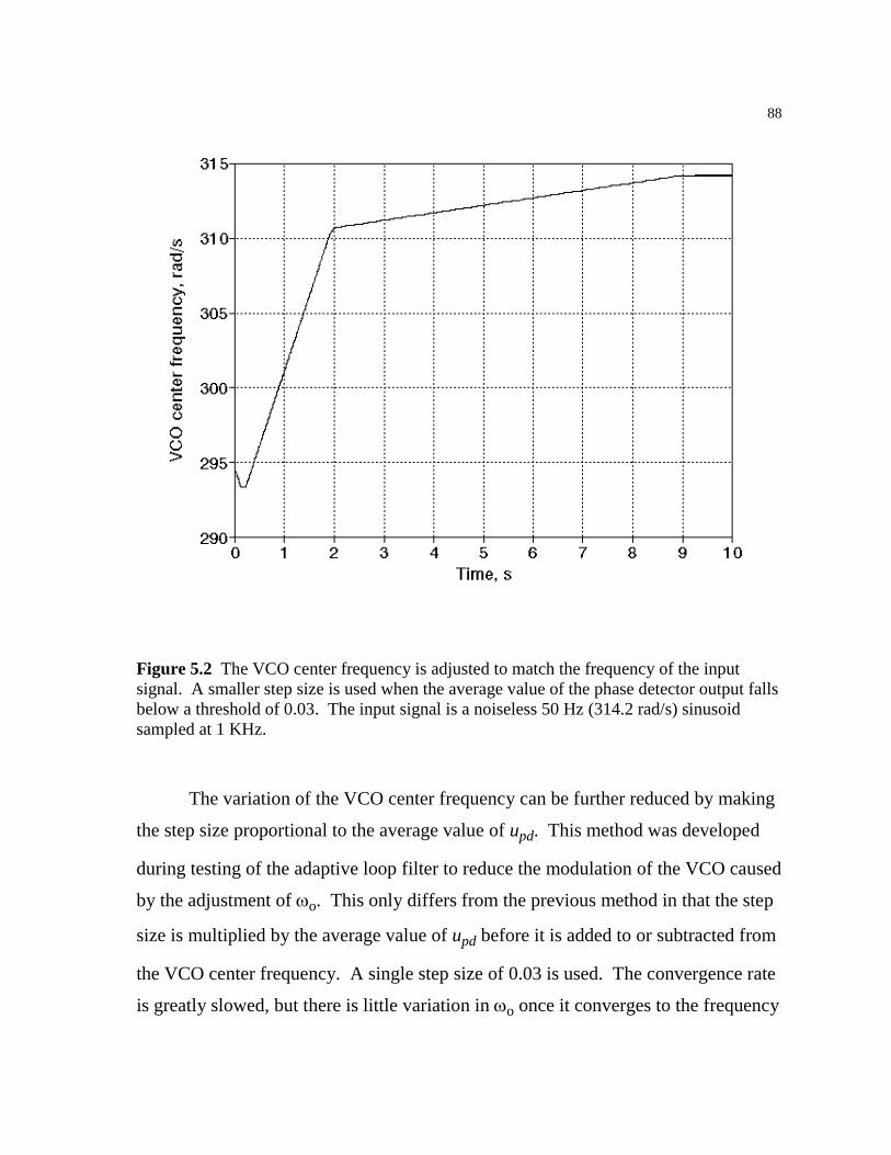
88
Figure 5.2 The VCO center frequency is adjusted to match the frequency of the input signal. A smaller step size is used when the average value of the phase detector output falls below a threshold of 0.03. The input signal is a noiseless 50 Hz (314.2 rad/s) sinusoid sampled at 1 KHz.
The variation of the VCO center frequency can be further reduced by making
the step size proportional to the average value of upd. This method was developed
during testing of the adaptive loop filter to reduce the modulation of the VCO caused
by the adjustment of ωo. This only differs from the previous method in that the step
size is multiplied by the average value of upd before it is added to or subtracted from
the VCO center frequency. A single step size of 0.03 is used. The convergence rate
is greatly slowed, but there is little variation in ωo once it converges to the frequency

89
of the input signal ωin. The convergence rate is shown in Fig. 5.3. If the robustness
of the adaptive loop filter algorithm can be improved, a larger step size for the
adjustment of ωo would decrease the convergence time and improve the tracking
performance of the phase-locked loop.
Figure 5.3 The VCO center frequency is again adjusted to match the frequency of the input signal. The step size of 0.03 is multiplied by the average value of the phase detector output, which causes the adjustment of ωo to decrease as the frequency converges on that of the input signal. The input signal is a noiseless 50 Hz (314.2 rad/s) sinusoid sampled at 1 KHz.
90
5.2 ADAPTIVE LOOP FILTER
In any adaptive system, the selection of an appropriate error signal is crucial for
proper operation. In the case of the phase-locked loop, the VCO output signal uvco is
desired to be a noiseless sinusoid with the same frequency as the input signal and
shifted in phase by 90°. The 90° phase shift is achieved by the adjustment of the
VCO center frequency to match the frequency of the input signal. Any noise present
in the input signal, however, will propagate through the phase detector and loop
filter and modulate the frequency of the VCO output signal uvco. It is the goal of the
adaptive loop filter to reduce the modulation of uvco while maintaining a lock on the
input signal.
Several adaptive algorithms were developed. The most promising of these
algorithms uses the Supervisor() subroutine to establish the initial conditions for the
phase-locked loop. The adaptive algorithm is not used until the PLL has locked and
the average value of upd falls below the threshold which indicates that ωo and ωin
are approximately equal.
In chapter 2, the VCO() subroutine was used to create the VCO output signal
uvco by calculating the sine of a phase angle which is advanced each iteration. The
CosineVCO() subroutine uses the same phase angle to create a signal uvcos which
lags uvco by 90°. Since uvco lags the conditioned input signal uagc by 90°, uvcos is
exactly out of phase with uagc. If the VCO center frequency ωo and the input signal
frequency ωin are equal, the inverted signal -uvcos is a sinusoid in phase with uagc
and with most of the noise removed. The only noise present in uvcos is due to the
propagation of noise from uagc through the phase detector and loop filter. The
adaptive algorithm attempts to adjust the loop filter coefficients to minimize the
difference between -uvcos and uagc, thus reducing the unnecessary modulation of
uvcos caused by the noise in the input signal.

91
At first, the difference between -uvcos and uagc may seem to be an appropriate
error signal for the adaptive loop filter. The phase detector, however, shifts the
frequency of uagc from ωin to 2ωin by multiplying uagc with uvco. This causes the
loop filter input and error signals to become uncorrelated, which prevents the proper
operation of the adaptive loop filter. To maintain correlation between the error
signal and the loop filter input upd, the desired signal -uvcos is also multiplied with
uvco to provide a similar frequency shift. This is illustrated in the block diagram of
Fig. 5.4.
PD LF
VCO
Low-Pass
-
u u
uu
u
agc pd
lfvco
vcos-
Figure 5.4 The block diagram of the phase-locked loop is shown with the adaptive loop filter and adjustment of the VCO center frequency ωo. The signal -uvcos is used as the desired version of the conditioned input uagc since it has the same frequency and phase but a greatly reduced noise level.
The algorithm is further complicated by the unknown amplitude of the
conditioned input signal, uagc. The AGC() subroutine can maintain a constant RMS
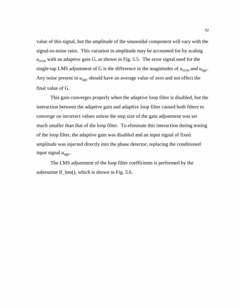
92
value of this signal, but the amplitude of the sinusoidal component will vary with the
signal-to-noise ratio. This variation in amplitude may be accounted for by scaling
uvcos with an adaptive gain G, as shown in Fig. 5.5. The error signal used for the
single-tap LMS adjustment of G is the difference in the magnitudes of uvcos and uagc.
Any noise present in uagc should have an average value of zero and not effect the
final value of G.
This gain converges properly when the adaptive loop filter is disabled, but the
interaction between the adaptive gain and adaptive loop filter caused both filters to
converge on incorrect values unless the step size of the gain adjustment was set
much smaller than that of the loop filter. To eliminate this interaction during testing
of the loop filter, the adaptive gain was disabled and an input signal of fixed
amplitude was injected directly into the phase detector, replacing the conditioned
input signal uagc.
The LMS adjustment of the loop filter coefficients is performed by the
subroutine lf_lms(), which is shown in Fig. 5.6.
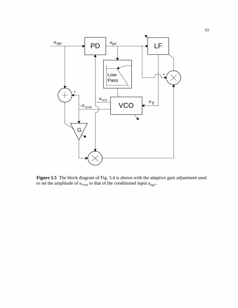
93
PD LF
VCO
Low-Pass
-
-
G
u u
uuu
agc pd
lfvcos
vco-
Figure 5.5 The block diagram of Fig. 5.4 is shown with the adaptive gain adjustment used to set the amplitude of uvcos to that of the conditioned input uagc.
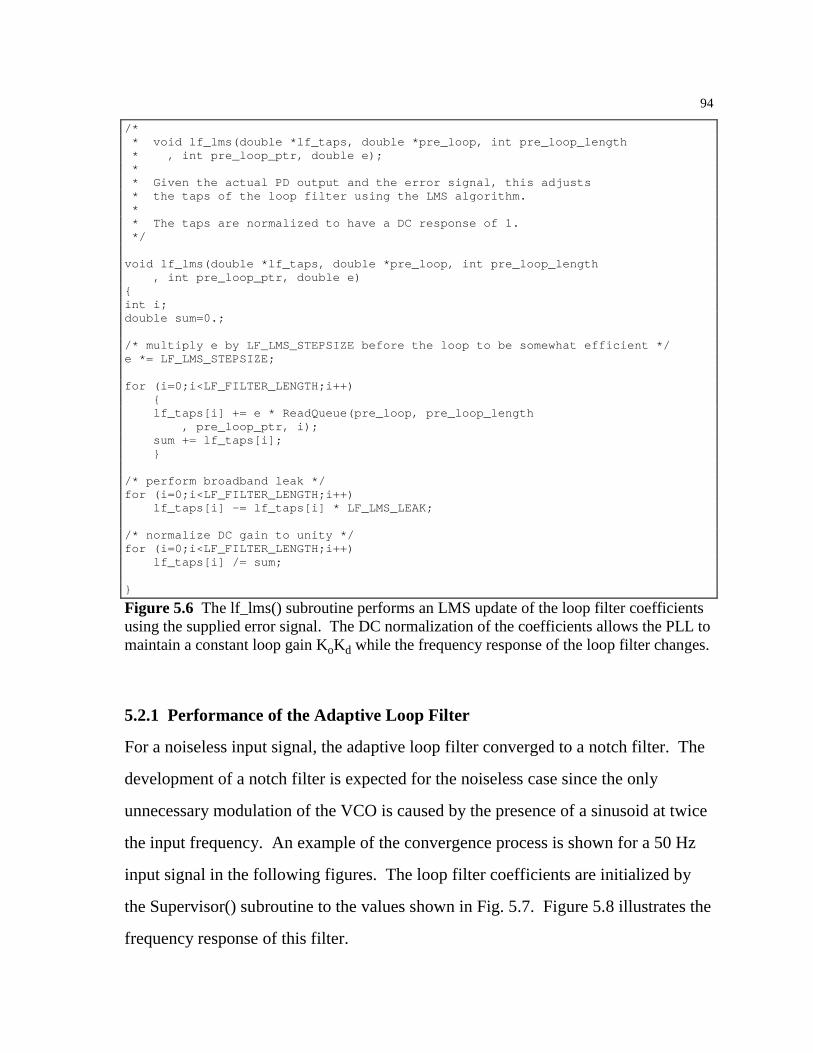
94
/* * void lf_lms(double *lf_taps, double *pre_loop, int pre_loop_length * , int pre_loop_ptr, double e); * * Given the actual PD output and the error signal, this adjusts * the taps of the loop filter using the LMS algorithm. * * The taps are normalized to have a DC response of 1. */ void lf_lms(double *lf_taps, double *pre_loop, int pre_loop_length , int pre_loop_ptr, double e) int i; double sum=0.; /* multiply e by LF_LMS_STEPSIZE before the loop to be somewhat efficient */ e *= LF_LMS_STEPSIZE; for (i=0;i<LF_FILTER_LENGTH;i++) lf_taps[i] += e * ReadQueue(pre_loop, pre_loop_length , pre_loop_ptr, i); sum += lf_taps[i]; /* perform broadband leak */ for (i=0;i<LF_FILTER_LENGTH;i++) lf_taps[i] -= lf_taps[i] * LF_LMS_LEAK; /* normalize DC gain to unity */ for (i=0;i<LF_FILTER_LENGTH;i++) lf_taps[i] /= sum;
Figure 5.6 The lf_lms() subroutine performs an LMS update of the loop filter coefficients using the supplied error signal. The DC normalization of the coefficients allows the PLL to maintain a constant loop gain KoKd while the frequency response of the loop filter changes.
5.2.1 Performance of the Adaptive Loop Filter
For a noiseless input signal, the adaptive loop filter converged to a notch filter. The
development of a notch filter is expected for the noiseless case since the only
unnecessary modulation of the VCO is caused by the presence of a sinusoid at twice
the input frequency. An example of the convergence process is shown for a 50 Hz
input signal in the following figures. The loop filter coefficients are initialized by
the Supervisor() subroutine to the values shown in Fig. 5.7. Figure 5.8 illustrates the
frequency response of this filter.
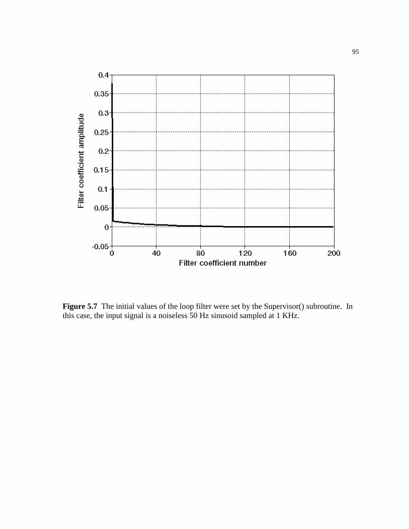
95
Figure 5.7 The initial values of the loop filter were set by the Supervisor() subroutine. In this case, the input signal is a noiseless 50 Hz sinusoid sampled at 1 KHz.
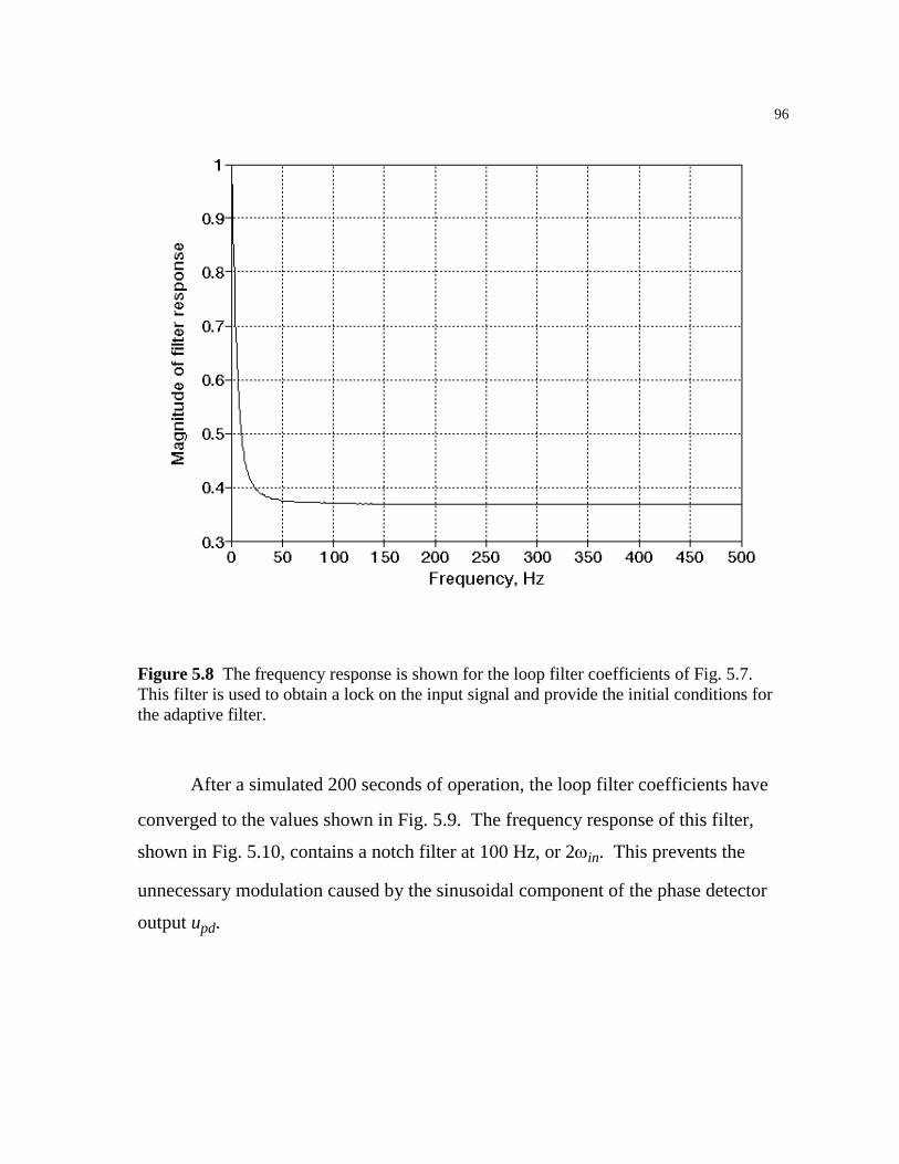
96
Figure 5.8 The frequency response is shown for the loop filter coefficients of Fig. 5.7. This filter is used to obtain a lock on the input signal and provide the initial conditions for the adaptive filter.
After a simulated 200 seconds of operation, the loop filter coefficients have
converged to the values shown in Fig. 5.9. The frequency response of this filter,
shown in Fig. 5.10, contains a notch filter at 100 Hz, or 2ωin. This prevents the
unnecessary modulation caused by the sinusoidal component of the phase detector
output upd.
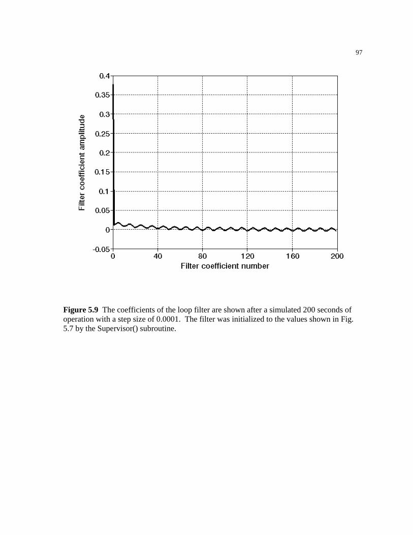
97
Figure 5.9 The coefficients of the loop filter are shown after a simulated 200 seconds of operation with a step size of 0.0001. The filter was initialized to the values shown in Fig. 5.7 by the Supervisor() subroutine.

98
Figure 5.10 The frequency response of the filter shown in Fig. 5.9 illustrates the notch filter developed by the adaptive algorithm. This filter removes the sinusoidal component of the phase detector output, minimizing the unnecessary modulation of the VCO.
The convergence of the first eleven coefficients is shown in Fig. 5.11 through
Fig. 5.13 for a step size of 0.0001. A significant amount of "ringing" is present,
which suggests that the step size should be reduced to prevent instability.
Simulations with various step sizes indicate that step sizes of 1x10⁻⁶ or less eliminate
this ringing, but require a prohibitive length of time to converge. For this reason,
step sizes between 1x10⁻⁵ and 1x10⁻⁴ were typically used, with smaller step sizes
substituted when the adaptive filter was suspected to be unstable. The convergence
of the first filter coefficient for three step sizes is shown in Fig. 5.14. Although the
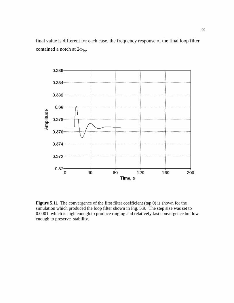
99
final value is different for each case, the frequency response of the final loop filter
contained a notch at 2ωin.
Figure 5.11 The convergence of the first filter coefficient (tap 0) is shown for the simulation which produced the loop filter shown in Fig. 5.9. The step size was set to 0.0001, which is high enough to produce ringing and relatively fast convergence but low enough to preserve stability.
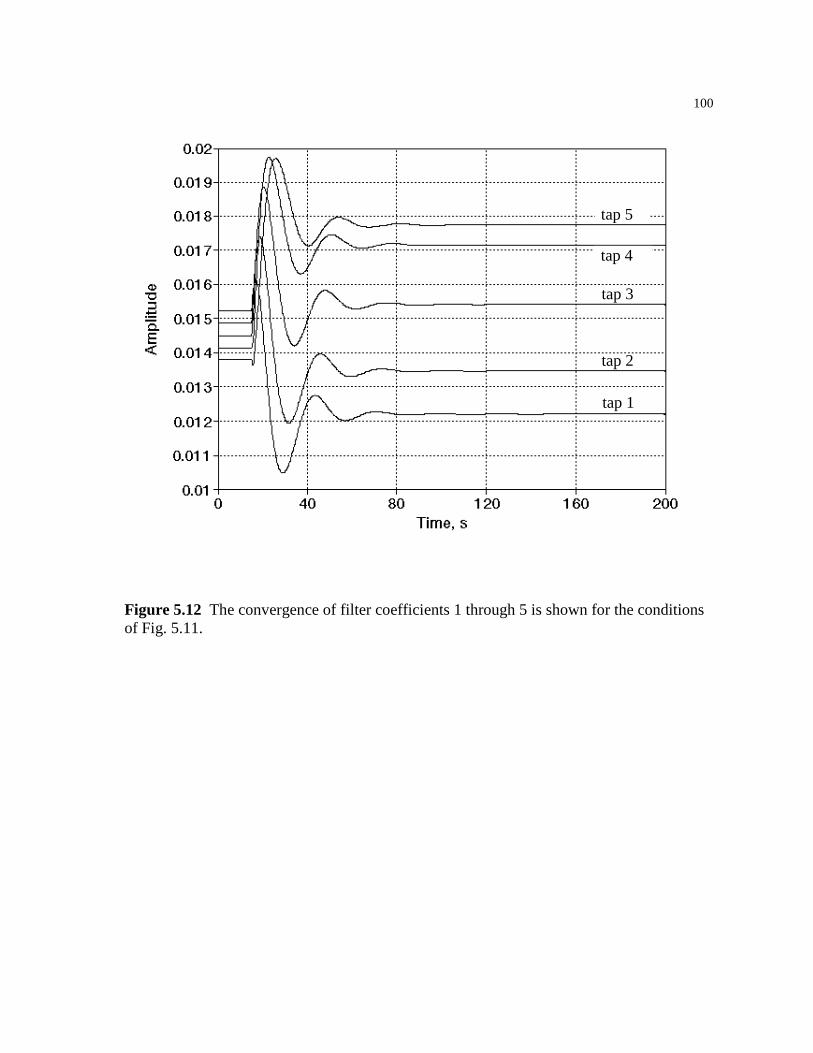
100
tap 5
tap 4
tap 3
tap 2
tap 1
Figure 5.12 The convergence of filter coefficients 1 through 5 is shown for the conditions of Fig. 5.11.

101
tap 6
tap 7
tap 10tap 9
tap 8
Figure 5.13 The convergence of filter coefficients 6 through 10 is shown for the conditions of Fig. 5.11.
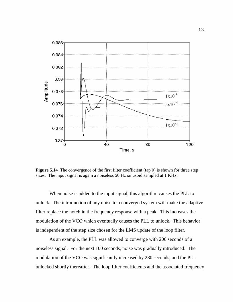
102
1x10
1x10
-4
-5
5x10⁻⁴
Figure 5.14 The convergence of the first filter coefficient (tap 0) is shown for three step sizes. The input signal is again a noiseless 50 Hz sinusoid sampled at 1 KHz.
When noise is added to the input signal, this algorithm causes the PLL to
unlock. The introduction of any noise to a converged system will make the adaptive
filter replace the notch in the frequency response with a peak. This increases the
modulation of the VCO which eventually causes the PLL to unlock. This behavior
is independent of the step size chosen for the LMS update of the loop filter.
As an example, the PLL was allowed to converge with 200 seconds of a
noiseless signal. For the next 100 seconds, noise was gradually introduced. The
modulation of the VCO was significantly increased by 280 seconds, and the PLL
unlocked shortly thereafter. The loop filter coefficients and the associated frequency
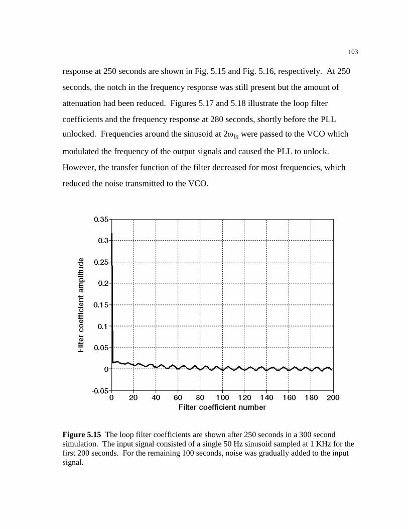
103
response at 250 seconds are shown in Fig. 5.15 and Fig. 5.16, respectively. At 250
seconds, the notch in the frequency response was still present but the amount of
attenuation had been reduced. Figures 5.17 and 5.18 illustrate the loop filter
coefficients and the frequency response at 280 seconds, shortly before the PLL
unlocked. Frequencies around the sinusoid at 2ωin were passed to the VCO which
modulated the frequency of the output signals and caused the PLL to unlock.
However, the transfer function of the filter decreased for most frequencies, which
reduced the noise transmitted to the VCO.
Figure 5.15 The loop filter coefficients are shown after 250 seconds in a 300 second simulation. The input signal consisted of a single 50 Hz sinusoid sampled at 1 KHz for the first 200 seconds. For the remaining 100 seconds, noise was gradually added to the input signal.
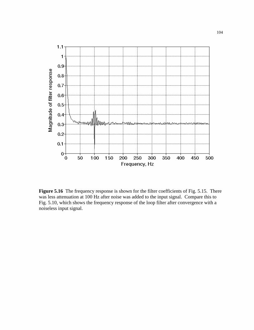
104
Figure 5.16 The frequency response is shown for the filter coefficients of Fig. 5.15. There was less attenuation at 100 Hz after noise was added to the input signal. Compare this to Fig. 5.10, which shows the frequency response of the loop filter after convergence with a noiseless input signal.

105
Figure 5.17 The loop filter coefficients are shown after 280 seconds in the same 300 second simulation, shortly before the PLL unlocked.

106
Figure 5.18 The frequency response is shown for the filter coefficients of Fig. 5.17. The attenuation of the sinusoid at 2ωin has decreased, while the attenuation of noise elsewhere has increased.
The adaptation of the first eleven coefficients is shown in Fig. 5.19 through
Fig. 5.21 for the same simulation. While the step size in this simulation is rather
large at 1x10⁻⁴, similar results were obtained with a step size of 1x10⁻⁶.

107
Figure 5.19 The adaptation of the first filter coefficient (tap 0) is shown. Noise is introduced on the input signal at 200 seconds and gradually increased. The PLL unlocks at approximately 280 seconds. A step size of 0.0001 was used in this simulation.
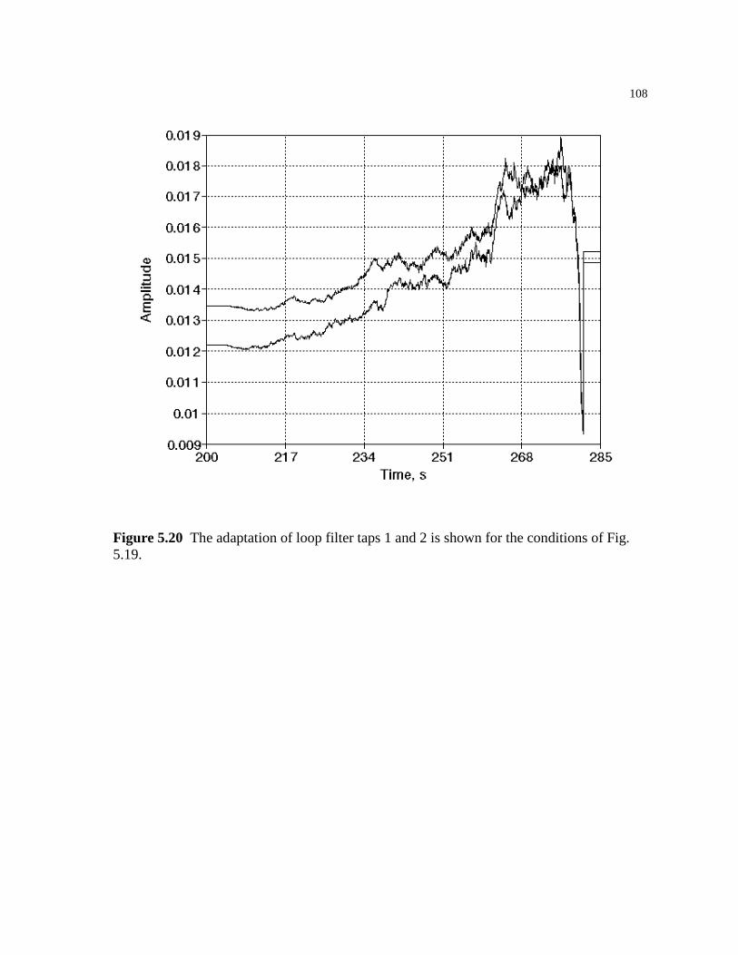
108
Figure 5.20 The adaptation of loop filter taps 1 and 2 is shown for the conditions of Fig. 5.19.
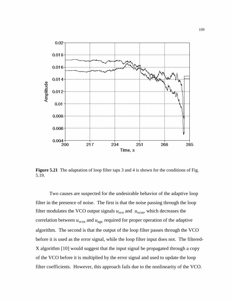
109
Figure 5.21 The adaptation of loop filter taps 3 and 4 is shown for the conditions of Fig. 5.19.
Two causes are suspected for the undesirable behavior of the adaptive loop
filter in the presence of noise. The first is that the noise passing through the loop
filter modulates the VCO output signals uvco and uvcos, which decreases the
correlation between uvcos and uagc required for proper operation of the adaptive
algorithm. The second is that the output of the loop filter passes through the VCO
before it is used as the error signal, while the loop filter input does not. The filtered-
X algorithm [10] would suggest that the input signal be propagated through a copy
of the VCO before it is multiplied by the error signal and used to update the loop
filter coefficients. However, this approach fails due to the nonlinearity of the VCO.
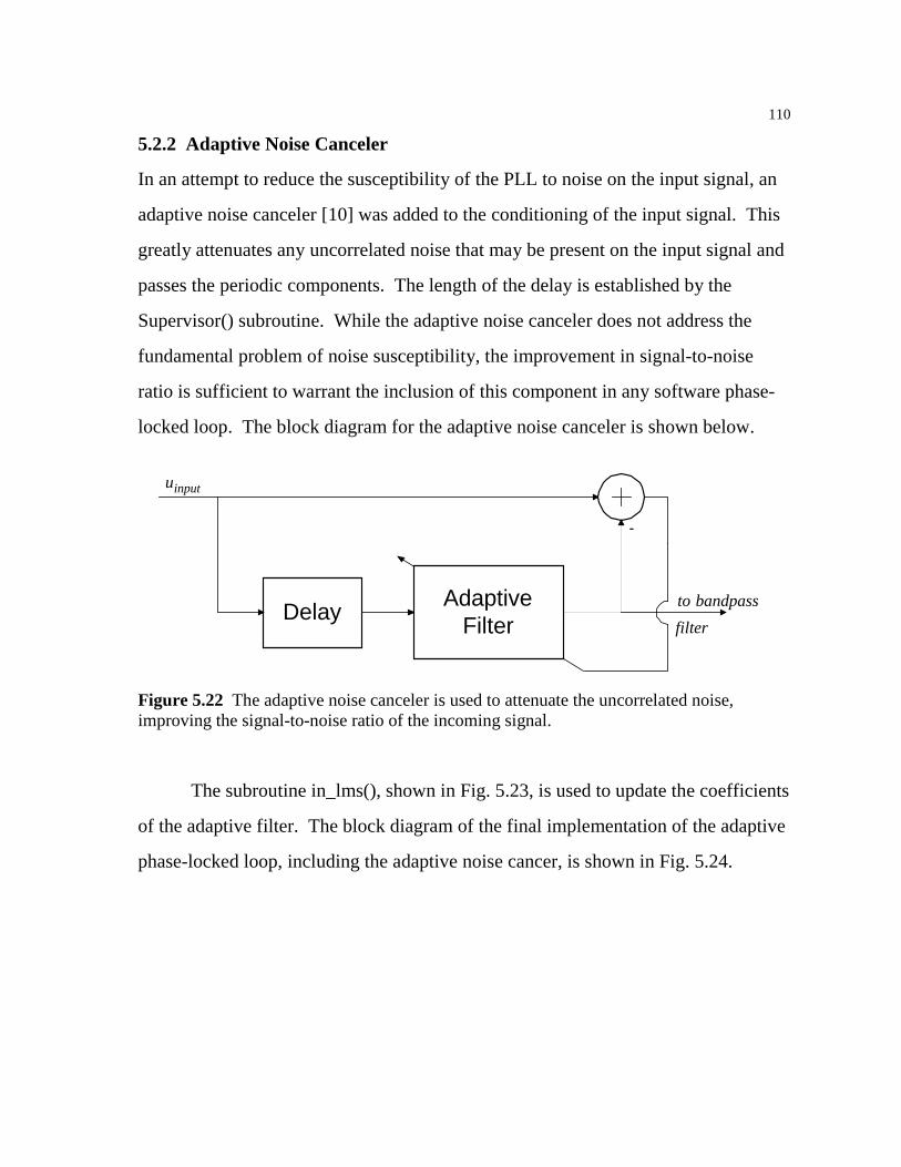
110
5.2.2 Adaptive Noise Canceler
In an attempt to reduce the susceptibility of the PLL to noise on the input signal, an
adaptive noise canceler [10] was added to the conditioning of the input signal. This
greatly attenuates any uncorrelated noise that may be present on the input signal and
passes the periodic components. The length of the delay is established by the
Supervisor() subroutine. While the adaptive noise canceler does not address the
fundamental problem of noise susceptibility, the improvement in signal-to-noise
ratio is sufficient to warrant the inclusion of this component in any software phase-
locked loop. The block diagram for the adaptive noise canceler is shown below.
Delay AdaptiveFilter
-
uinput
to bandpassfilter
Figure 5.22 The adaptive noise canceler is used to attenuate the uncorrelated noise, improving the signal-to-noise ratio of the incoming signal.
The subroutine in_lms(), shown in Fig. 5.23, is used to update the coefficients
of the adaptive filter. The block diagram of the final implementation of the adaptive
phase-locked loop, including the adaptive noise cancer, is shown in Fig. 5.24.

111
/* * void in_lms(double *in_taps, double *input, int input_length, int input_ptr * , double *canceled, int canceled_length, int canceled_ptr, int in_delay); * * This is an adaptive noise canceler based upon Figure 12.36 on page 352 * of Widrow/Stearns "Adaptive Signal Processing". It is a self-tuning * filter which passes only the periodic components. * * + * input ----->+-------------------------->sum---> e * | ^ - * | | * \-->delay-->adaptive filter->+----> periodic output * ^ * | * e --/ * * The delay is established by Supervisor() and is set by the constant * IN_DELAY_NUM_PERIODS (number of periods of the VCO center frequency). * Unlike the variable-length averaging filters, this number does not * change after it is initialized by Supervisor(). */ void in_lms(double *in_taps, double *input, int input_length, int input_ptr , double *canceled, int canceled_length, int canceled_ptr, int in_delay) int i; double e; e = ReadQueue(input, input_length, input_ptr, 0) - ReadQueue(canceled, canceled_length, canceled_ptr, 0); /* multiply e by IN_LMS_STEPSIZE before the loop for efficiency */ e *= IN_LMS_STEPSIZE; for (i=0;i<IN_FILTER_LENGTH;i++) in_taps[i] += e * ReadQueue(input, input_length, input_ptr, in_delay + i);
Figure 5.23 The in_lms() subroutine updates the coefficients of the adaptive filter used in the adaptive noise canceler. This provides a computationally inexpensive method of improving the signal-to-noise ratio of the input signal.

112
Band
-Pa
ssA
GC
Hilb
ert
Tran
sfor
mLo
w-
Pass
Del
ayA
dapt
ive
Filte
r
-
PD
LF
VC
O
Low
-Pa
ss-
- G
Figu
re 5
.24
The
blo
ck d
iagr
am o
f the
fina
l im
plem
enta
tion
of th
e ad
aptiv
e ph
ase-
lock
ed lo
op is
show
n. T
his v
ersio
n in
clud
esth
e lo
ck d
etec
tor,
the
adju
stmen
t of t
he V
CO c
ente
r fre
quen
cy, a
nd th
e ad
aptiv
e no
ise c
ance
ler.
u inp
ut
u loc
k
113
5.2.3 Future Work
The adaptive loop filter must be made robust in the presence of noise. After all, if
noise were not present, there would be no need for a phase-locked loop. One
method that does not use the adaptive algorithm presented here is to allow a subset
of the Supervisor() algorithm to operate in the background, making incremental
adjustments to the loop filter parameters τ1 and τ2 based upon the signal-to-noise
ratio of the input signal. While this would never be able to create the notch filter of
Fig. 5.10, the Supervisor() algorithm is known to be reliable and this method would
likely prevent the PLL from ever unlocking due to noise. Tracking performance
would be limited by the step size used to adjust the VCO center frequency ωo.

114
Appendix A The Signal Generation Utility
Variations on the following program were used to generate input signals for the
software phase-locked loop. The basic version shown here as Fig. A.1 supports the
generation of fixed frequency, swept frequency, and frequency modulated sinusoids
with varying amounts of random noise.
/* * siggen.c * * This program is used to generate test signals for the PLL. * * Three types are permitted: * * - standard sine wave: specify frequency, amplitude of sine wave, * amplitude of white noise (peak). * - linear frequency sweep: given a lower frequency, an upper frequency, * the delay before sweeping begins, the time required to sweep, * and the amplitude of the sine wave, the program generates a * wave beginning with the lower frequency and linearly increases * the frequency until the upper frequency is reached. * - modulated sine wave: given a center frequency and sinusoid amplitude, * the delay before modulation begins, and the amplitude and frequency * of the modulator, the program generates a wave whose frequency * varies around the center frequency by the amplitude of the * modulator. Both modulator and output are sinusoidal. */ #define PI 3.1415 #include <stdio.h> #include <math.h> #include <stdlib.h> main() FILE *binary; /* binary output for use by PLL */ FILE *matlab; /* ASCII output for MATLAB */ FILE *freq; /* ASCII output containing freq as function of sample # */ float sampling_freq; long int response; /* user input */ float lower,upper; /* for sweeping frequency */ float center; /* center of modulated frequency */ float amplitude; /* amplitude of main frequency */ float modtime; /* time allocated for sweeping or modulation */
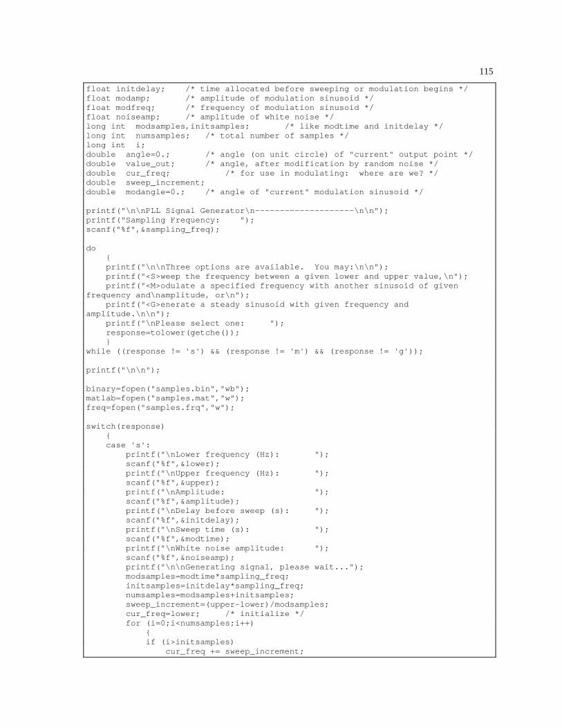
115
float initdelay; /* time allocated before sweeping or modulation begins */ float modamp; /* amplitude of modulation sinusoid */ float modfreq; /* frequency of modulation sinusoid */ float noiseamp; /* amplitude of white noise */ long int modsamples,initsamples; /* like modtime and initdelay */ long int numsamples; /* total number of samples */ long int i; double angle=0.; /* angle (on unit circle) of "current" output point */ double value_out; /* angle, after modification by random noise */ double cur_freq; /* for use in modulating: where are we? */ double sweep_increment; double modangle=0.; /* angle of "current" modulation sinusoid */ printf("\n\nPLL Signal Generator\n--------------------\n\n"); printf("Sampling Frequency: "); scanf("%f",&sampling_freq); do printf("\n\nThree options are available. You may:\n\n"); printf("<S>weep the frequency between a given lower and upper value,\n"); printf("<M>odulate a specified frequency with another sinusoid of given frequency and\namplitude, or\n"); printf("<G>enerate a steady sinusoid with given frequency and amplitude.\n\n"); printf("\nPlease select one: "); response=tolower(getche()); while ((response != 's') && (response != 'm') && (response != 'g')); printf("\n\n"); binary=fopen("samples.bin","wb"); matlab=fopen("samples.mat","w"); freq=fopen("samples.frq","w"); switch(response) case 's': printf("\nLower frequency (Hz): "); scanf("%f",&lower); printf("\nUpper frequency (Hz): "); scanf("%f",&upper); printf("\nAmplitude: "); scanf("%f",&litude); printf("\nDelay before sweep (s): "); scanf("%f",&initdelay); printf("\nSweep time (s): "); scanf("%f",&modtime); printf("\nWhite noise amplitude: "); scanf("%f",&noiseamp); printf("\n\nGenerating signal, please wait..."); modsamples=modtime*sampling_freq; initsamples=initdelay*sampling_freq; numsamples=modsamples+initsamples; sweep_increment=(upper-lower)/modsamples; cur_freq=lower; /* initialize */ for (i=0;i<numsamples;i++) if (i>initsamples) cur_freq += sweep_increment;

116
angle += (2.0 * PI * cur_freq / sampling_freq); if (angle > (2.0 * PI)) /* wraparound */ angle -= (2.0 * PI); value_out=amplitude*sin(angle) + noiseamp*2.0*(0.5-rand()/32767.0); /* this generates random # from -0.5 .. 0.5 ^^^^^^^^^^^^^^^^^^ */ fwrite(&value_out,sizeof(double),1,binary); fprintf(matlab,"%f\n",value_out); fprintf(freq,"%f\n",cur_freq); break; case 'm': printf("\nCenter frequency (Hz): "); scanf("%f",¢er); printf("\nAmplitude: "); scanf("%f",&litude); printf("\nModulation frequency (Hz): "); scanf("%f",&modfreq); printf("\nModulation amplitude: "); scanf("%f",&modamp); printf("\nDelay before modulation (s): "); scanf("%f",&initdelay); printf("\nModulation time (s): "); scanf("%f",&modtime); printf("\nWhite noise amplitude: "); scanf("%f",&noiseamp); printf("\n\nGenerating signal, please wait..."); modsamples=modtime*sampling_freq; initsamples=initdelay*sampling_freq; numsamples=modsamples+initsamples; cur_freq=center; /* initialize */ for (i=0;i<numsamples;i++) if (i>initsamples) cur_freq = center + modamp*sin(modangle); /* modulation */ modangle += (2.0 * PI * modfreq / sampling_freq); if (modangle > (2.0 * PI)) modangle -= (2.0 * PI); angle += (2.0 * PI * cur_freq / sampling_freq); if (angle > (2.0 * PI)) /* wraparound */ angle -= (2.0 * PI); value_out=amplitude*sin(angle)+noiseamp*2.0*(0.5-rand()/32767.0); /* this generates random # from -0.5 .. 0.5 ^^^^^^^^^^^^^^^^^^ */ fwrite(&value_out,sizeof(double),1,binary); fprintf(matlab,"%f\n",value_out); fprintf(freq,"%f\n",cur_freq); break; case 'g': printf("\nFrequency (Hz): "); scanf("%f",¢er); printf("\nAmplitude: "); scanf("%f",&litude); printf("\nSimulation Time (s): "); scanf("%f",&modtime); printf("\nWhite noise amplitude: "); scanf("%f",&noiseamp); printf("\n\nGenerating signal, please wait...");
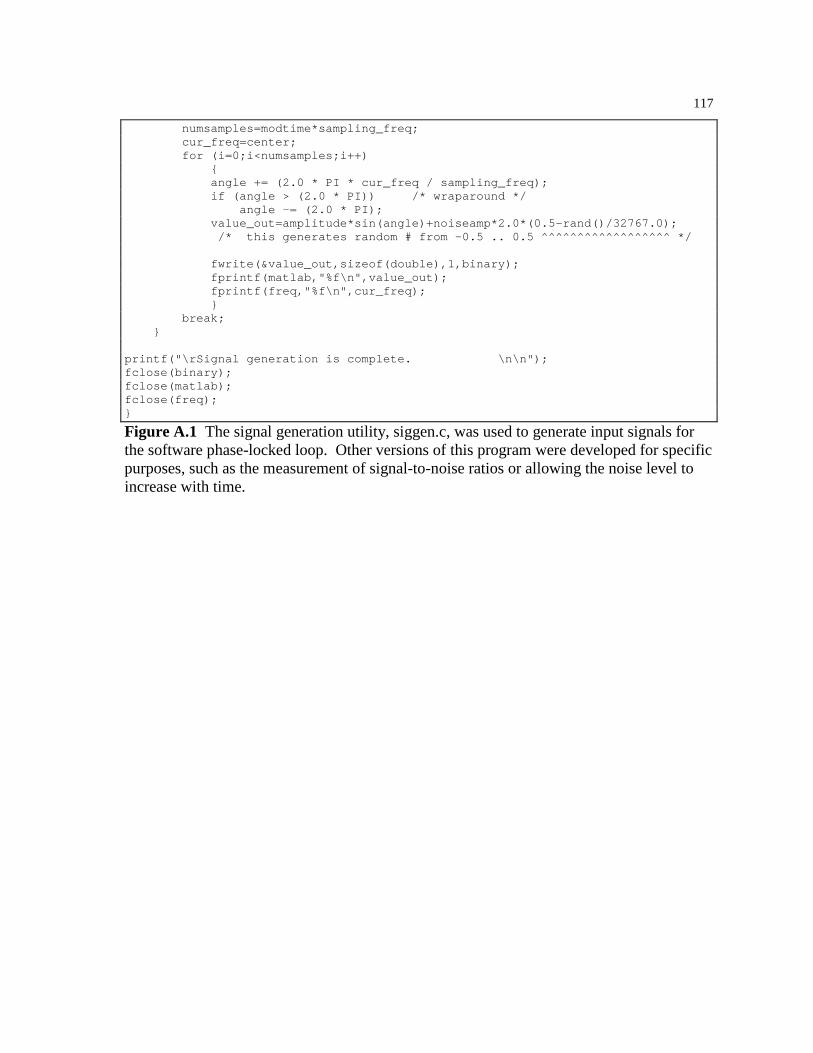
117
numsamples=modtime*sampling_freq; cur_freq=center; for (i=0;i<numsamples;i++) angle += (2.0 * PI * cur_freq / sampling_freq); if (angle > (2.0 * PI)) /* wraparound */ angle -= (2.0 * PI); value_out=amplitude*sin(angle)+noiseamp*2.0*(0.5-rand()/32767.0); /* this generates random # from -0.5 .. 0.5 ^^^^^^^^^^^^^^^^^^ */ fwrite(&value_out,sizeof(double),1,binary); fprintf(matlab,"%f\n",value_out); fprintf(freq,"%f\n",cur_freq); break; printf("\rSignal generation is complete. \n\n"); fclose(binary); fclose(matlab); fclose(freq);
Figure A.1 The signal generation utility, siggen.c, was used to generate input signals for the software phase-locked loop. Other versions of this program were developed for specific purposes, such as the measurement of signal-to-noise ratios or allowing the noise level to increase with time.

118
Appendix B The Phase-Locked Loop Program
The subroutines used to implement the software phase locked loop were included as
figures in the relevant chapters. The main program, consisting mostly of
initialization, data collection, and function calls, is shown here as Fig. B.1.
The code was compiled with Microsoft C 6.0 using the command:
cl /AH /G2 pll.c
and with Turbo C 2.0 using the command:
tcc -w -mh -G -N -1 -O -Z -f87 pll.c
/* * pll.c: Phase Locked Loop, main program * * Kevin Rolfes, 01/16/1994 * * From block diagram: * * 1. Samples from disk -> input[] * 2. Adaptive noise canceler: input[] -> canceled[] * 3. Pre-loop filtering: canceled[] -> filtered_input[] * 4. Auto-Gain Correction of filtered_input[] -> agc[] * (actually filtered_input[] -> agc_intermed -> agc[]) * 5. Phase detector: agc[] * vco_output[] -> pre_loop_filter[] * 6. Loop filter: pre_loop_filter[] -> post_loop_filer[] * 7. VCO: post_loop_filter[] -> vco_output[] * 8. 90-degree phase shift: agc[] -> input_shifted[] * 9. Lock Detector Multiplier: * input_shifted[] * vco_output[delayed] = lock_pre_filter[] * 10. Lock Detector Filter: lock_pre_filter[] -> lock_post_filter[] * 11. Averaging filter applied to PD output: * pre_loop_filter[] -> pd_out_avg[] * 12. Averaging filter applied to LF output: * post_loop_filter[] -> post_loop_avg[] * 13. Second VCO, 90 degrees out of phase with original VCO: * post_loop_avg[] -> vco_shifted[] * 14. Gain applied to vco_shifted to match agc output: * vco_shifted[] * vco_shifted_gain -> vco_shifted[] * 15. Construction of desired PD output: * vco_shifted[delayed by 1] * vco_output[delayed by 1] = desired */

119
/* definitions */ #undef WRITE_ALWAYS /* (undef = log every 57 iterations) */ #undef DEBUG /* (undef=off, def=on) */ #define SAMPLING_FREQUENCY 1000 /* for testing of fixed PLL, assume 1KHz*/ #define INPUT_LENGTH 1024 /* length of input[] array */ #define SUPER_POWER_LENGTH 33 /* initial length of power spectrum */ /* performed by the Supervisor() */ /* (must be 2^N + 1) */ #define SUPER_ZETA 0.707 /* initial value of zeta */ #define SUPER_SNR_THRESHOLD 20 /* minimum SNR to exit Supervisor() loop*/ /* see Supervisor() comments for details*/ #define LF_FILTER_LENGTH 200 /* number of taps for loop filter */ /* (must be < signal length) */ #define FILTERED_INPUT_LENGTH INPUT_LENGTH /* length of filtered_input[] */ #define CANCELED_LENGTH INPUT_LENGTH /* length of canceled[] */ #define AGC_LENGTH INPUT_LENGTH /* length of agc[] */ #define AGC_READ_LENGTH 200 /* number of samples for averaging */ #define AGC_OFFSET_STEP_PERCENT 0.005 /* limit offset change to 0.5%/iter */ #define AGC_GAIN_STEP_PERCENT 0.01 /* limit gain changes to 1.0%/iter */ #define AGC_INTERMED_LENGTH AGC_READ_LENGTH /* intermediate signal for rms measuring*/ #define AGC_TARGET_RMS 0.707 /* target an rms value of 0.707 */ #define PRE_LOOP_FILTER_LENGTH INPUT_LENGTH /* length of array */ #define VCO_OUTPUT_LENGTH INPUT_LENGTH /* length of array */ #define POST_LOOP_FILTER_LENGTH INPUT_LENGTH /* length of array */ #define POST_LOOP_FILTER_NUM_PERIODS 50 /* number of periods of VCO center frequency to average LF output over */ #define TWO_PI 6.28318530718 #define PI 3.14159265359 #define HALF_PI 1.5707963268 #define HILBERT_LENGTH 51 /* taps for Hilbert transform filter */ /* must be odd for symmetry about the center*/ #define INPUT_SHIFTED_LENGTH FILTERED_INPUT_LENGTH /* length of phase shifted signal */ #define VCO_SHIFTED_LENGTH FILTERED_INPUT_LENGTH #define LOCK_PRE_FILTER_LENGTH FILTERED_INPUT_LENGTH /* length of pre-filter signal in lock detector */ #define LOCK_POST_FILTER_LENGTH FILTERED_INPUT_LENGTH /* length of post-filter signal in lock detector*/ #define LOCK_FILTER_NUM_PERIODS 10 /* number of periods of vco center frequency to average samples over*/ #define LOCK_DETECTOR_THRESHOLD 0. /* if lock detector output drops below this value, call Supervisor()*/ #define LOCK_DETECTOR_DELAY 4000 /* 4 seconds @ fs=1KHz */ /* iterations between call to Supervisor() and first lock detect test */

120
#define PD_OUT_AVG_LENGTH INPUT_LENGTH /* length of circular queue for PD output after averaging filter */ #define PD_FILTER_NUM_PERIODS 25 /* number of periods of vco center frequency to avg PD output over */ #define VCO_STEPSIZE 3.E-2 /* step size used by proportional adjustment of the VCO center */ /* frequency, when the magnitude of the average PD output is */ /* above the threshold set by PD_AVG_THRESHOLD. */ /* This step size is multiplied by the magnitude of the average */ /* PD output before it is added or subtracted to/from the VCO */ /* center frequency. */ #define VCO_STEP_FRACTION 1. /* this is multiplied by VCO_STEPSIZE to produce the step size */ /* used when the average PD output is below the threshold. */ #define PD_AVG_THRESHOLD 0.01 /* the threshold below which the averaged PD output must fall */ /* for us to consider the VCO center frequency = the input freq */ #define VCO_SHIFTED_GAIN_STEP 1.E-4 /* The step size used by the single-tap LMS filter used to make */ /* the vco_shifted signal amplitude approximately equal to that */ /* of the input signal after the AGC. */ #define LF_LMS_DELAY 15000 /* 15 seconds @ fs=1KHz */ /* iterations between call to Supervisor() and first call to lf_lms() */ #define LF_LMS_STEPSIZE 1.E-4 /* step size for adaptive loop filter */ #define LF_LMS_LEAK 0. /* multiplicative broadband leak applied to LMS taps of LF */ #define IN_FILTER_LENGTH 100 #define IN_LMS_STEPSIZE 1.E-8 /* step size for adaptive noise canceler on input signal */ #define IN_DELAY_NUM_PERIODS 3. /* number of periods of the VCO center frequency to be used */ /* as delay between input signal and adaptive filter. */ /* includes */ #include <stdio.h> #include <stdlib.h> #include <math.h> #include <dos.h> /* Turbo C, sound(), sleep(), and nosound() */ /* function prototypes */ double ReadQueue(double *start_addr, int length, int first_ptr, int index); void WriteQueue(double *start_addr, int length, int first_ptr, int index , double value); int PushQueue(double *start_addr, int length, int first_ptr, double value); void PowerSpectrum(double *input_addr, int input_length, int input_first_ptr , double *spectrum, int power_length); int PreFilter(double *input, int input_length, int input_ptr , double *filtered_input, int filtered_input_length, int filtered_input_ptr , double *prefilter_workspace); void CreateFilterTaps(double tau1,double tau2,double *lf_taps); int FilterSignal(double *input_addr, int input_length, int input_first_ptr , double *output_addr, int output_length, int output_first_ptr , double *taps, int filter_length, int delay, double gain); int AGC(double *input, int input_length, int input_ptr, double *agc , int agc_length, int agc_ptr, double *agc_average

121
, double *agc_rms, int agc_read_length, double *offset, double *gain , double *agc_intermed, int agc_intermed_length, int *agc_intermed_ptr); int PhaseDetector(double *filtered_input, int filtered_input_length , int filtered_input_ptr, double *vco_output, int vco_output_length , int vco_output_ptr, double *pre_loop_filter , int pre_loop_filter_length, int pre_loop_filter_ptr); int VCO(double *post_loop_filter, int post_loop_filter_length , int post_loop_filter_ptr, double *vco_output , int vco_output_length, int vco_output_ptr , double vco_center, double *vco_angle); int CosineVCO(double *vco_shifted, int vco_shifted_length, int vco_shifted_ptr , double vco_shifted_gain, double vco_angle); void FillHilbert(double *hilbert); int HilbertTransform(double *input_addr, int input_length, int input_first_ptr , double *output_addr, int output_length, int output_first_ptr , double *hilbert); int LockDetectorMultiplier(double *input_shifted , int input_shifted_length, int input_shifted_ptr , double *vco_output, int vco_output_length, int vco_output_ptr , double *output, int output_length, int output_ptr); int AveragingFilter(double *pre_filter, int pre_filter_length , int pre_filter_ptr, double *post_filter, int post_filter_length , int post_filter_ptr, double vco_center, int *filter_length , int num_periods); double Supervisor(double *vco_center, double *lf_taps, double *input_addr , int input_length, int input_first_ptr, double *prefilter_workspace , int *in_delay, double *in_taps, double *agc_average, int agc_read_length); /* loop gain is returned */ void lf_lms(double *lf_taps, double *pre_loop, int pre_loop_length , int pre_loop_ptr, double desired); void in_lms(double *in_taps, double *input, int input_length, int input_ptr , double *canceled, int canceled_length, int canceled_ptr, int in_delay); void main() double *input; /* for circular queue for input signal */ int input_ptr=0; /* pointer for current 'start' of queue (subscript) */ double *canceled; /* queue for input after adaptive noise cancelation */ int canceled_ptr=0; /* pointer for start of queue */ FILE *samples; /* file from which incoming samples are read */ double d, d2, e; /* generic doubles for temporary use */ int i; /* generic int for loops */ double *filtered_input;/* agc signal after pre-loop filtering */ int filtered_input_ptr=0; /* pointer for start of queue (subscript) */ double *agc_intermed; /* after offset correction, before gain correction */ int agc_intermed_ptr=0; /* pointer for start of agc_intermed queue */ double *agc; /* input signal after auto-gain correction */ int agc_ptr=0; /* pointer for start of queue */ double agc_average=0.; /* used by AGC() to keep running average */ double agc_rms=0.; /* used by AGC() to keep running RMS value */ double agc_offset=0.; /* current offset value used by AGC() */ double agc_gain=1.; /* current gain value used by AGC() */ double *pre_loop_filter; /* between phase detector and loop fiter */ int pre_loop_filter_ptr=0.; /* pointer for start of queue */ double *vco_output; /* signal, after VCO */ int vco_output_ptr=0.; /* pointer for start of queue */ double *post_loop_filter; /* between loop filter and VCO */ int post_loop_filter_ptr=0.; /* pointer for start of queue */ double vco_angle=0.; /* used by VCO() to keep track of current angle */ FILE *log1; /* for dumping data to disk for later analysis */

122
FILE *log2; FILE *log3; FILE *log4; FILE *log5; FILE *log6; FILE *log7; FILE *log8; FILE *log9; FILE *log10; FILE *log11; FILE *log12; double *input_shifted; /* input signal after phase shifting */ int input_shifted_ptr=0; /* pointer for start of queue */ double *vco_shifted; /* VCO output after 90 degree phase shift */ int vco_shifted_ptr=0; double *lock_pre_filter; /* lock detector: after multiplication */ int lock_pre_filter_ptr=0; double *lock_post_filter; /* lock detector: after filtering */ int lock_post_filter_ptr=0; int lock_filter_length=0; /* lock detector filter length (dynamic) */ double *pd_out_avg; /* PD output: after filtering */ int pd_out_avg_ptr=0; int pd_filter_length=0; /* PD output filter length (dynamic) */ double vco_center; /* center frequency of VCO in radians/sec */ double *lf_taps; /* tap weights for loop filter */ double *in_taps; /* taps for adaptive noise canceler */ int in_delay; /* delay between input and adaptive noise canceler */ double *hilbert; /* taps for Hilbert transform filter */ double prefilter_workspace[4]; /* holds parameters & past outputs for PreFilter() -- */ /* see PreFilter() documentation for details. */ long int lock_test_disable_count; /* timing variable for disabling of lock detector test */ /* after Supervisor() is called. */ long int lms_disable_count; /* timing variable for disabling of lf_lms algorithm */ /* after Supervisor() is called. */ double desired; /* desired PD output, constructed from VCO output */ double vco_shifted_gain=1.; /* gain factor applied to vco_shifted */ long int log_file_count; /* temporary variable to log every N iterations */ double loop_gain; /* gain applied to output of normalized loop filter */ #ifdef DEBUG printf("pll: start of code\n"); #endif /* initialization - create arrays and clear the contents */ /************************************************************************/ /****** create and clear input queue (circular) */ if ((input=(double *)malloc(INPUT_LENGTH*sizeof(double)))==NULL) fprintf(stderr,"\npll: error creating input queue\n"); exit(1); for (i=0;i<INPUT_LENGTH;i++) input[i]=0; /****** create and clear canceled curcular queue */
123
if ((canceled=(double *)malloc(CANCELED_LENGTH*sizeof(double)))==NULL) fprintf(stderr,"\npll: error creating canceled queue\n"); exit(1); for (i=0;i<CANCELED_LENGTH;i++) canceled[i]=0; /****** create space for loop filter tap coefficients */ if ((lf_taps=(double *)malloc(LF_FILTER_LENGTH*sizeof(double)))==NULL) fprintf(stderr,"\npll: error creating storage for loop filter taps\n"); exit(1); /****** create space for adaptive noise canceler taps */ if ((in_taps=(double *)malloc(IN_FILTER_LENGTH*sizeof(double)))==NULL) fprintf(stderr,"\npll: error creating storage for noise canceler taps\n"); exit(1); /****** create and initialize filtered_input circular queue */ if ((filtered_input=(double *)malloc(FILTERED_INPUT_LENGTH*sizeof(double)))==NUL L) fprintf(stderr,"\npll: error creating filtered_input queue\n"); exit(1); for (i=0;i<FILTERED_INPUT_LENGTH;i++) filtered_input[i]=0.0; /****** create and initialize input_shifted circular queue */ if ((input_shifted=(double *)malloc(INPUT_SHIFTED_LENGTH*sizeof(double)))==NULL) fprintf(stderr,"\npll: error creating input_shifted queue\n"); exit(1); for (i=0;i<INPUT_SHIFTED_LENGTH;i++) input_shifted[i]=0.0; /****** create and initialize agc_intermed circular queue */ if ((agc_intermed=(double *)malloc(AGC_INTERMED_LENGTH*sizeof(double)))==NULL) fprintf(stderr,"\npll: error creating agc_intermed queue\n"); exit(1); for (i=0;i<AGC_INTERMED_LENGTH;i++) agc_intermed[i]=0.0; /****** create and initialize agc circular queue */ if ((agc=(double *)malloc(AGC_LENGTH*sizeof(double)))==NULL) fprintf(stderr,"\npll: error creating agc queue\n");

124
exit(1); for (i=0;i<AGC_LENGTH;i++) agc[i]=0.0; /****** create and initialize pre_loop_filter circular queue */ if ((pre_loop_filter=(double *)malloc(PRE_LOOP_FILTER_LENGTH*sizeof(double)))==N ULL) fprintf(stderr,"\npll: error creating pre_loop_filter queue\n"); exit(1); for (i=0;i<PRE_LOOP_FILTER_LENGTH;i++) pre_loop_filter[i]=0.0; /****** create and initialize post_loop_filter circular queue */ if ((post_loop_filter=(double *)malloc(POST_LOOP_FILTER_LENGTH*sizeof(double)))= =NULL) fprintf(stderr,"\npll: error creating post_loop_filter queue\n"); exit(1); for (i=0;i<POST_LOOP_FILTER_LENGTH;i++) post_loop_filter[i]=0.0; /****** create and initialize vco_output circular queue */ if ((vco_output=(double *)malloc(VCO_OUTPUT_LENGTH*sizeof(double)))==NULL) fprintf(stderr,"\npll: error creating vco_output queue\n"); exit(1); for (i=0;i<VCO_OUTPUT_LENGTH;i++) vco_output[i]=0.0; /****** create and initialize vco_shifted circular queue */ if ((vco_shifted=(double *)malloc(VCO_SHIFTED_LENGTH*sizeof(double)))==NULL) fprintf(stderr,"\npll: error creating vco_shifted queue\n"); exit(1); for (i=0;i<VCO_SHIFTED_LENGTH;i++) vco_shifted[i]=0.0; /****** create and initialize Hilbert transformer taps */ if ((hilbert=(double *)malloc(HILBERT_LENGTH*sizeof(double)))==NULL) fprintf(stderr,"\npll: error creating hilbert taps\n"); exit(1); FillHilbert(hilbert); /* initialize it */ /****** create and initialize lock_pre_filter circular queue */ if ((lock_pre_filter=(double *)malloc(LOCK_PRE_FILTER_LENGTH*sizeof(double)))==N ULL)
125
fprintf(stderr,"\npll: error creating lock_pre_filter queue\n"); exit(1); for (i=0;i<LOCK_PRE_FILTER_LENGTH;i++) lock_pre_filter[i]=0.; /****** create and initialize lock_post_filter circular queue */ if ((lock_post_filter=(double *)malloc(LOCK_POST_FILTER_LENGTH*sizeof(double)))= =NULL) fprintf(stderr,"\npll: error creating lock_post_filter queue\n"); exit(1); for (i=0;i<LOCK_POST_FILTER_LENGTH;i++) lock_post_filter[i]=0.; /****** create and initialize pd_out_avg circular queue */ if ((pd_out_avg=(double *)malloc(PD_OUT_AVG_LENGTH*sizeof(double)))==NULL) fprintf(stderr,"\npll: error creating pd_out_avg queue\n"); exit(1); for (i=0;i<PD_OUT_AVG_LENGTH;i++) pd_out_avg[i]=0.; /* open input file */ if ((samples=fopen("samples.bin","rb"))==NULL) fprintf(stderr,"\npll: cannot open samples.bin\n"); exit(1); /* open log files */ log1=fopen("input.mat","w"); log2=fopen("agc.mat","w"); log3=fopen("unlocked.mat","w"); log4=fopen("filtered.mat","w"); log5=fopen("vco_outp.mat","w"); log6=fopen("pre_loop.mat","w"); log7=fopen("post_loo.mat","w"); log8=fopen("shifted.mat","w"); log9=fopen("pre_lock.mat","w"); log10=fopen("post_loc.mat","w"); log12=fopen("pd_avg.mat","w"); /* erase existing files that will be appended to in each iteration * due to constraints on the number of open files */ log11=fopen("vco_shif.mat","w"); fclose(log11); log11=fopen("desired.mat","w"); fclose(log11); log11=fopen("center.mat","w"); fclose(log11); log11=fopen("vco_gain.mat","w"); fclose(log11); log11=fopen("canceled.mat","w"); fclose(log11);
126
log_file_count=0; /* Before we call Supervisor() for some initial conditions, let's fill * the input buffer with some samples for it to work with. */ i=0; while ((i<INPUT_LENGTH) && ((int)fread((void *)(&d),sizeof(double),1,samples))) input_ptr=PushQueue(input,INPUT_LENGTH,input_ptr,d); i++; /* test for premature EOF */ if (i<INPUT_LENGTH) fprintf(stderr,"pll: file does not contain enough samples.\n"); exit(1); /* go to Supervisor() for initial guesses at vco_center and filter taps[]. */ loop_gain = Supervisor(&vco_center, lf_taps, input, INPUT_LENGTH , input_ptr, prefilter_workspace, &in_delay, in_taps, &agc_average , AGC_READ_LENGTH); /* zero the lock detector and lms timers: disabled during lock process */ lock_test_disable_count = 0; lms_disable_count = 0; /* write initial lf_taps to logfile */ log11=fopen("starttap.mat","w"); for (i=0;i<LF_FILTER_LENGTH;i++) fprintf(log11,"%f\n",lf_taps[i]); fclose(log11); /*** end of initialization ***************************************************/ /* main loop *****************************************************************/ #ifdef DEBUG printf("pll: beginning main loop\n"); #endif while ((int)fread((void *)(&d),sizeof(double),1,samples)) /* repeat until we reach the end of the file */ /* put this sample in the input queue */ input_ptr=PushQueue(input,INPUT_LENGTH,input_ptr,d); /* call the adaptive noise canceler */ canceled_ptr = FilterSignal(input, INPUT_LENGTH, input_ptr , canceled, CANCELED_LENGTH, canceled_ptr, in_taps, IN_FILTER_LENGTH , in_delay, 1.); /* update the adaptive noise canceler taps */ in_lms(in_taps, input, INPUT_LENGTH, input_ptr, canceled , CANCELED_LENGTH, canceled_ptr, in_delay); /* perform pre-loop filtering on input signal */ filtered_input_ptr = PreFilter(canceled, CANCELED_LENGTH, canceled_ptr , filtered_input, FILTERED_INPUT_LENGTH, filtered_input_ptr , prefilter_workspace);
127
/* Perform AGC on filtered input signal */ agc_ptr=AGC(filtered_input, FILTERED_INPUT_LENGTH, filtered_input_ptr, agc , AGC_LENGTH, agc_ptr, &agc_average , &agc_rms, AGC_READ_LENGTH, &agc_offset, &agc_gain , agc_intermed, AGC_INTERMED_LENGTH, &agc_intermed_ptr); /* call phase detector */ pre_loop_filter_ptr = PhaseDetector(agc, AGC_LENGTH , agc_ptr, vco_output, VCO_OUTPUT_LENGTH, vco_output_ptr , pre_loop_filter, PRE_LOOP_FILTER_LENGTH, pre_loop_filter_ptr); /* call loop filter of PLL */ post_loop_filter_ptr = FilterSignal(pre_loop_filter, PRE_LOOP_FILTER_LENGTH , pre_loop_filter_ptr, post_loop_filter, POST_LOOP_FILTER_LENGTH , post_loop_filter_ptr, lf_taps, LF_FILTER_LENGTH, 0, loop_gain); /* call VCO of PLL */ vco_output_ptr=VCO(post_loop_filter, POST_LOOP_FILTER_LENGTH , post_loop_filter_ptr, vco_output, VCO_OUTPUT_LENGTH , vco_output_ptr, vco_center, &vco_angle); /* shift input signal 90 degrees for lock detection */ input_shifted_ptr = HilbertTransform(agc, AGC_LENGTH, agc_ptr , input_shifted, INPUT_SHIFTED_LENGTH, input_shifted_ptr, hilbert); /* multiply shifted input signal with VCO output for lock detection */ lock_pre_filter_ptr=LockDetectorMultiplier(input_shifted ,INPUT_SHIFTED_LENGTH, input_shifted_ptr ,vco_output, VCO_OUTPUT_LENGTH, vco_output_ptr ,lock_pre_filter, LOCK_PRE_FILTER_LENGTH, lock_pre_filter_ptr); /* filter output of LockDetectorMultiplier() for lock detection */ lock_post_filter_ptr=AveragingFilter(lock_pre_filter , LOCK_PRE_FILTER_LENGTH, lock_pre_filter_ptr, lock_post_filter , LOCK_POST_FILTER_LENGTH, lock_post_filter_ptr , vco_center, &lock_filter_length, LOCK_FILTER_NUM_PERIODS); /* averaging filter for PD output - used by adaptive algorithm */ pd_out_avg_ptr=AveragingFilter(pre_loop_filter , PRE_LOOP_FILTER_LENGTH, pre_loop_filter_ptr, pd_out_avg , PD_OUT_AVG_LENGTH, pd_out_avg_ptr, vco_center, &pd_filter_length , PD_FILTER_NUM_PERIODS); /* adjust gain applied to vco_shifted to make its amplitude * approximately equal to that of the AGC output (minus noise). * * Changed 22-jun-93 to only adjust the gain after the PD output * falls below the threshold, indicating 90 degrees difference between * input signal and VCO output. * Changed 7-jul-93 to make the amount of change proportional to the * error and to use the previous iteration's AGC output since the * new vco_shifted hasn't been generated yet. */ if (fabs(ReadQueue(pd_out_avg, PD_OUT_AVG_LENGTH, pd_out_avg_ptr, 0)) < PD_AVG_THRESHOLD) d = fabs(ReadQueue(agc, AGC_LENGTH, agc_ptr, 1)); d2 = fabs(ReadQueue(vco_shifted,VCO_SHIFTED_LENGTH,vco_shifted_ptr,0)); vco_shifted_gain += VCO_SHIFTED_GAIN_STEP * (d - d2) * d2;
128
/* get VCO output (shifted by 90 degrees) by using the cosine of * the present VCO angle (normal output is sine) and apply the * variable gain to this signal */ vco_shifted_ptr = CosineVCO(vco_shifted, VCO_SHIFTED_LENGTH , vco_shifted_ptr, vco_shifted_gain, vco_angle); /* construct a desired PD output by multiplying the VCO output with * the shifted version of itself. */ desired = ReadQueue(vco_shifted, VCO_SHIFTED_LENGTH, vco_shifted_ptr, 1) * ReadQueue(vco_output, VCO_OUTPUT_LENGTH, vco_output_ptr, 1) * -1.; /* perform adjustment of VCO center frequency: * if the magnitude of the average PD output is greater than * PD_AVG_THRESHOLD, just add/subtract pd_avg * VCO_STEPSIZE to/from * the VCO center frequency. Otherwise, add/subtract pd_avg * * VCO_STEP_FRACTION * VCO_STEPSIZE to/from the VCO center frequency. */ d = VCO_STEPSIZE; /* temporary variable for step size */ if (fabs(ReadQueue(pd_out_avg, PD_OUT_AVG_LENGTH, pd_out_avg_ptr, 0)) < PD_AVG_THRESHOLD) d *= VCO_STEP_FRACTION; vco_center += ReadQueue(pd_out_avg, PD_OUT_AVG_LENGTH, pd_out_avg_ptr, 0) * d; /* check the lock detector and lf_lms test counter: if these are not yet * enabled, increment the counters. Otherwise, test the output * of the lock detector to see if Supervisor() should be called, * and look at the PD output to see if lf_lms should be called. */ /* First, the lock detector: */ if (lock_test_disable_count < LOCK_DETECTOR_DELAY) lock_test_disable_count++; fprintf(log3,"%d\n",1); /* test disabled: write 1 to log file */ else /* otherwise, perform lock detector test */ if (ReadQueue(lock_post_filter, LOCK_POST_FILTER_LENGTH , lock_post_filter_ptr, 0) < LOCK_DETECTOR_THRESHOLD) /* failed test */ log11=fopen("badtaps.mat","w"); /* log taps to disk */ for (i=0;i<LF_FILTER_LENGTH;i++) fprintf(log11,"%f\n",lf_taps[i]); fclose(log11); loop_gain = Supervisor(&vco_center, lf_taps, input, INPUT_LENGTH , input_ptr, prefilter_workspace, &in_delay, in_taps , &agc_average, AGC_READ_LENGTH); lock_test_disable_count = 0; /* zero the timer */ lms_disable_count = 0; fprintf(log3,"%d\n",1); /* unlocked: write 1 to log file */ sound(20); sleep(1); nosound(); /* notify me */ else fprintf(log3,"%d\n",0); /* normal operation - write 0 to log */

129
/* Then the lf_lms subroutine: */ if (lms_disable_count < LF_LMS_DELAY) lms_disable_count++; else if (fabs(ReadQueue(pd_out_avg, PD_OUT_AVG_LENGTH, pd_out_avg_ptr, 0)) < PD_AVG_THRESHOLD) /* error is desired - PD output */ e = desired - ReadQueue(pre_loop_filter, PRE_LOOP_FILTER_LENGTH ,pre_loop_filter_ptr, 0); lf_lms(lf_taps, pre_loop_filter, PRE_LOOP_FILTER_LENGTH ,pre_loop_filter_ptr, e); log_file_count++; if (log_file_count == 200000L) log11=fopen("taps200s.mat","w"); for (i=0;i<LF_FILTER_LENGTH;i++) fprintf(log11,"%f\n",lf_taps[i]); fclose(log11); if (log_file_count == 210000L) log11=fopen("taps210s.mat","w"); for (i=0;i<LF_FILTER_LENGTH;i++) fprintf(log11,"%f\n",lf_taps[i]); fclose(log11); if (log_file_count == 220000L) log11=fopen("taps220s.mat","w"); for (i=0;i<LF_FILTER_LENGTH;i++) fprintf(log11,"%f\n",lf_taps[i]); fclose(log11); if (log_file_count == 230000L) log11=fopen("taps230s.mat","w"); for (i=0;i<LF_FILTER_LENGTH;i++) fprintf(log11,"%f\n",lf_taps[i]); fclose(log11); if (log_file_count == 240000L) log11=fopen("taps240s.mat","w"); for (i=0;i<LF_FILTER_LENGTH;i++) fprintf(log11,"%f\n",lf_taps[i]); fclose(log11); if (log_file_count == 250000L) log11=fopen("taps250s.mat","w"); for (i=0;i<LF_FILTER_LENGTH;i++) fprintf(log11,"%f\n",lf_taps[i]); fclose(log11);

130
if (log_file_count == 260000L) log11=fopen("taps260s.mat","w"); for (i=0;i<LF_FILTER_LENGTH;i++) fprintf(log11,"%f\n",lf_taps[i]); fclose(log11); if (log_file_count == 270000L) log11=fopen("taps270s.mat","w"); for (i=0;i<LF_FILTER_LENGTH;i++) fprintf(log11,"%f\n",lf_taps[i]); fclose(log11); if (log_file_count == 280000L) log11=fopen("taps280s.mat","w"); for (i=0;i<LF_FILTER_LENGTH;i++) fprintf(log11,"%f\n",lf_taps[i]); fclose(log11); if (log_file_count == 290000L) log11=fopen("taps290s.mat","w"); for (i=0;i<LF_FILTER_LENGTH;i++) fprintf(log11,"%f\n",lf_taps[i]); fclose(log11); #ifndef WRITE_ALWAYS if (log_file_count%57 == 0) printf("Time: %1.2f s\n",(float)(log_file_count)/SAMPLING_FREQUENCY); #else if (log_file_count%100 == 0) printf("Time: %1.1f s\n",(float)(log_file_count)/SAMPLING_FREQUENCY); #endif /* write present values to log files */ fprintf(log1,"%f\n",ReadQueue(input,INPUT_LENGTH,input_ptr,0)); fprintf(log2,"%f\n",ReadQueue(agc,AGC_LENGTH,agc_ptr,0)); fprintf(log4,"%f\n",ReadQueue(filtered_input,FILTERED_INPUT_LENGTH,filtered_ input_ptr,0)); fprintf(log5,"%f\n",ReadQueue(vco_output,VCO_OUTPUT_LENGTH,vco_output_ptr,0) ); fprintf(log6,"%f\n",ReadQueue(pre_loop_filter, PRE_LOOP_FILTER_LENGTH, pre_l oop_filter_ptr,0)); fprintf(log7,"%f\n",ReadQueue(post_loop_filter, POST_LOOP_FILTER_LENGTH, pos t_loop_filter_ptr,0)); fprintf(log8,"%f\n",ReadQueue(input_shifted,INPUT_SHIFTED_LENGTH,input_shift ed_ptr,0)); fprintf(log9,"%f\n",ReadQueue(lock_pre_filter,LOCK_PRE_FILTER_LENGTH,lock_pr e_filter_ptr,0)); fprintf(log10,"%f\n",ReadQueue(lock_post_filter,LOCK_POST_FILTER_LENGTH,lock _post_filter_ptr,0)); fprintf(log12,"%f\n",ReadQueue(pd_out_avg,PD_OUT_AVG_LENGTH,pd_out_avg_ptr,0 )); log11=fopen("vco_shif.mat","a"); fprintf(log11,"%f\n",ReadQueue(vco_shifted,VCO_SHIFTED_LENGTH,vco_shifted_pt r,0)); fclose(log11); log11=fopen("desired.mat","a");

131
fprintf(log11,"%f\n",desired); fclose(log11); log11=fopen("center.mat","a"); fprintf(log11,"%f\n",vco_center); fclose(log11); log11=fopen("agc_gain.mat","a"); fprintf(log11,"%f\n",agc_gain); fclose(log11); log11=fopen("agc_offs.mat","a"); fprintf(log11,"%f\n",agc_offset); fclose(log11); log11=fopen("vco_gain.mat","a"); fprintf(log11,"%f\n",vco_shifted_gain); fclose(log11); log11=fopen("canceled.mat","a"); fprintf(log11,"%f\n",ReadQueue(canceled, CANCELED_LENGTH, canceled_ptr,0)); fclose(log11); log11=fopen("tap0.mat","a"); fprintf(log11,"%f\n",lf_taps[0]); fclose(log11); log11=fopen("tap1.mat","a"); fprintf(log11,"%f\n",lf_taps[1]); fclose(log11); log11=fopen("tap2.mat","a"); fprintf(log11,"%f\n",lf_taps[2]); fclose(log11); log11=fopen("tap3.mat","a"); fprintf(log11,"%f\n",lf_taps[3]); fclose(log11); log11=fopen("tap4.mat","a"); fprintf(log11,"%f\n",lf_taps[4]); fclose(log11); log11=fopen("tap5.mat","a"); fprintf(log11,"%f\n",lf_taps[5]); fclose(log11); log11=fopen("tap6.mat","a"); fprintf(log11,"%f\n",lf_taps[6]); fclose(log11); log11=fopen("tap7.mat","a"); fprintf(log11,"%f\n",lf_taps[7]); fclose(log11); log11=fopen("tap8.mat","a"); fprintf(log11,"%f\n",lf_taps[8]); fclose(log11); log11=fopen("tap9.mat","a"); fprintf(log11,"%f\n",lf_taps[9]); fclose(log11); log11=fopen("tap10.mat","a"); fprintf(log11,"%f\n",lf_taps[10]); fclose(log11); log11=fopen("tap11.mat","a"); fprintf(log11,"%f\n",lf_taps[11]); fclose(log11); log11=fopen("tap12.mat","a"); fprintf(log11,"%f\n",lf_taps[12]); fclose(log11); log11=fopen("tap13.mat","a"); fprintf(log11,"%f\n",lf_taps[13]); fclose(log11); log11=fopen("tap14.mat","a"); fprintf(log11,"%f\n",lf_taps[14]);
132
fclose(log11); #ifndef WRITE_ALWAYS #endif /* clean up and leave */ fclose(log1); fclose(log2); fclose(log3); fclose(log4); fclose(log5); fclose(log6); fclose(log7); fclose(log8); fclose(log9); fclose(log10); fclose(log12); fclose(samples); log11=fopen("finaltap.mat","w"); for (i=0;i<LF_FILTER_LENGTH;i++) fprintf(log11,"%f\n",lf_taps[i]); fclose(log11); log11=fopen("intaps.mat","w"); for (i=0;i<IN_FILTER_LENGTH;i++) fprintf(log11,"%f\n",in_taps[i]); fclose(log11); exit(0);
Figure B.1 This program implements the adaptive phase-locked loop shown in Fig. 5.24 using the subroutines presented in chapters 1 through 5.

133
Appendix C References
[1] P.A. Nelson and S.J. Elliot, Active Control of Sound (Academic Press
Limited, London, 1992).
[2] David C. Baumann (The Modal Identification Approach to Multimodal
Acoustic Cancellation in a Long Duct, Ph.D. Thesis, UW-Madison 1992), personal
correspondance, August 1993.
[3] Paul Horowitz and Winfield Hill, The Art of Electronics, 2nd ed.
(Cambridge University Press, Cambridge, UK, 1989).
[4] Roland E. Best, Phase-Locked Loops (McGraw-Hill, New York, 1984).
[5] Rodger E. Ziemer, William H. Tranter, and D. Ronald Fannin, Signals
and Systems: Continuous and Discrete, 2nd ed. (Macmillan Publishing Company,
New York, 1989).
[6] Alan V. Oppenheim and Ronald W. Schafer, Digital Signal Processing
(Prentice-Hall, Englewood Cliffs, NJ, 1975).
[7] Mitchell J. Gebheim (Real-Time Implementation of a Digital Phase-
Lock-Loop, M.S. Thesis, UW-Madison 1993), personal correspondance, January
1994.
[8] C. S. Burrus and T. W. Parks, DFT/FFT and Convolution Algorithms
(John Wiley & Sons, New York, 1985).
[9] Willis J. Tompkins, Ed., Biomedical Digital Signal Processing,
manuscript, 1992.

134
[10] Bernard Widrow and Samuel D. Stearns, Adaptive Signal Processing
(Prentice-Hall, Englewood Cliffs, NJ, 1985).
[11] R. A. Greiner, personal correspondance, March 1993.