the b.a.s. speaker · onkyo has just announced a successor to the t-4055, their only tuner. this...
TRANSCRIPT

THE B.A.S. SPEAKEREDITOR-IN-CHIEF: Michael Riggs THE BOSTON AUDIO SOCIETYCOORDINATING EDITOR: David Temple P.O. BOX 7STAFF: Henry Belot, Robert Borden, Joyce Brinton, BOSTON, MASSACHUSETTS 02215Dana Craig, Frank Farlow, Robert Graham, LawrenceKaufman, James Lindquist, Peter Mitchell, JohnSchlafer, Jack Stevens, James Topali, Peter Watters
PUBLISHER: James Brinton, President, BASVOLUME 5, NUMBER 7APRIL 1977
THE BOSTON AUDIO SOCIETY DOES NOT ENDORSE OR CRITICIZE PRODUCTS, DEALERS,OR SERVICES. OPINIONS EXPRESSED HEREIN REFLECT THE VIEWS OF THEIR AUTHORSAND ARE FOR THE INFORMATION OF THE MEMBERS.
In This IssueAs promised, this month's feature attraction is on phono preamps (again). Local luminaries
Tom Holman and Mark Davis have teamed up to examine the input impedances of a number of phonosections. The results are interesting and sometimes dismaying. Once you've read Tom Holman'sarticle, you'll probably be itching to check out your own preamp, as well as other components,cables, etc. Enter Mark Davis with plans for a black-box impedance tester, and Davis-BrintonEngineering with a kit for same. (Members interested in buying a kit should see the note onpage 14 of this issue.
Tom Holman's other effort in this issue underlines the need for high pass filtering in phonopreamps.
You'll also find Scott Kent's WGBH hum filter and Bob Sellman's Dolby deemphasis modifica-tion for the Dyna FM-5.
Finally, we need a volunteer to take over "In the Literature," at least for the summer. DanaCraig is going to be away and will not be able to continue. "In the Literature" is one of our mostpopular features. If you can help us keep it alive, either as a contributor or as the "Lit" editor,write to Box 7 or call Michael Riggs -- soon.
Membership dues are $14 per year (October 1 to September 30) or portion thereof. Dues include a one-yearsubscription to the BAS Speaker . (Note that almost the full amount of dues is allocated to production ofthe Speaker . The local activities of the BAS are strictly self-supporting.) For further information and appli-cation form, write to: The Boston Audio Society, P.O. Box 7, Kenmore Square Station, Boston, Mass. 02215.
Copyright ©1977 The Boston Audio SocietyVol. 5, Num. 7 April 1977 The BAS SpeakerOCRed from printed copy - errors possible.
Mea CulpaLast month The BAS Speaker violated one of the cardinal rules of journalism -- no matter
what else you get wrong, always spell the names right. In the meeting summary, Dr. Bruce R.Maier's name was spelled incorrectly (consistently, but nonetheless incorrectly). After his kindwords about the BAS and his exciting presentation, this is doubly embarrassing. I hope he andyou can forgive our carelessness.
Mea Further Culpa
In the February 1977 note on AFKA Records, the following errors appeared: On SK-298, theharpsichordist is Mark Kroll not Don Angle; on SK-299, the correct players are Carol Liber-mann and Mark Kroll. Also, SK-301 will be available after June 1, 1977 but its number has beenchanged from SK-301 to SK-276. Everything else in the item (not much) is (said to be) correct(as of this writing).
BAS Telephone DirectoryFrank Farlow has compiled a list of BAS members and their telephone numbers. If you want
a copy of this membership directory, send a stamped self-addressed envelope to Frank c/o P.O.Box 7.
For Sale*Crown IC-150A and Crown OC-150, with cabinets for both. Both units one year old, in mint con-dition. Will ship prepaid in factory boxes. Sold new for $1300; will sell for $900. K. D. Al-ford, Jr., P.O. Box 21, Owensboro, KY 42301, (502) 685-5890.
*Hewlett-Packard 3580 spectrum analyser options 1 and 2, $3800. Larry C. Sanders, (303) 667-5000, ext. 2817 (work), (303) 667-8977 (home).
*Infinity 2000-II speakers, four-way, floor-standing system with Walsh tweeter, one month old,with blank warranty cards and packing. New list is $658 per pair; will sell for $420. StephenBayle, (617) 547-2836.
*Sound Concepts SD-50 audio delay units with slight scratches or cabinet dents. These units meetall electrical specifications and come with a new unit's warranty. Available at 25 percent off re-tail, or $450 prepaid from Sound Concepts, P.O. Box 135, Brookline, MA 02146, (617) 734-5070.
*Yamaha CR 1000 receiver, one year old, pristine condition, price negotiable. Jerome C. Tan-ous, 303 Simms Avenue, Council Bluffs, Iowa 51501, (712) 322-6023 (call after 6 p.m.).
*Acoustat X full-range electrostatic speakers, built-in servo-loop (integral) 100-watt amps.Teak with white linen grill. New. (919) 449-4132, days only.
*Dynaco ST-400M amplifier with meters and fans. (617) 427-7325, after 5 and weekends.
Wanted*Gately SM6A or SPM6 mixer in good condition. Roger Foster, 62 Hemlock, Winnipeg, ManitobaR2H1L7, Canada, (204) 452-2825.
New England Conservatory Summer WorkshopsThe New England Conservatory of Music will hold a summer school from June 27 to August 5,
1977, featuring workshops, courses, and master classes. Highlights will be one-week workshopsin electronic music, June 27 - July 1, with Robert Ceely, and basic audio and recording techniquesfor music educators, July 25 - July 29, with Robert Rachdorf.
-2-

The intense electronic music workshop will include discussion and hands-on use of ARP,MOOG, and EML synthesizers, two- and four-channel equipment, and various other devicesfound in an electronic music studio.
The basic audio and recording techniques workshop will cover the use of all types of record-ing equipment, preventive maintenance, editing techniques, and recording procedures for var-ious-sized ensembles.
Washington, D. C., Hi-Fi Show
The Washington, D.C., high fidelity show, held biannually at the Hotel Washington, blastedvisitors and exhibitors alike for three solid days. Although a number of the audio "biggies,such as Advent and Yamaha, were conspicuously absent, local talent seemed to fill the gap.
To a great extent, each person's interests govern what exhibits he attends. I plead guilty topurposely avoiding some while lingering longer at others. I hope my account will not make forfrustrating reading if your interests differ.
ESS demonstrated Dr. Heil's first full-range AMT speaker system. This system utilizes acompletely new type of air motion transformer (consisting of vertically-arranged diaphragmsdriven by carbon rods) to handle low frequencies. Called Transar (it does resemble somethingfrom Star Trek), this system is a bipolar radiator which must be biamped. To prevent wave can-cellation, a small partition extends from both sides of the bass transformer. No cabinet is in-volved, and ESS claims that Transar is free of resonance and has better transient ability than con-ventional drivers. Their demonstration seemed to substantiate this.
Overall, the system gave an excellent account of itself. However, because of the extremelysmall room, I could not judge its power handling capability or its dispersion depth, and other spa-tial characteristics. For some forgotten reason, conventional amplifiers will require a simpleand supposedly inexpensive modification to drive Transar. The demonstration was conductedwith Ortofon MC-20 cartridge and head amp, Infinity tonearm, ESS preamp, and two ESS poweramps. They are priced at $1000 per speaker.
The Dahlquist-G.A.S. exhibit attracted a great number of spectators. The DQ-10's wereset up with a center channel (6 dB down), Dahlquist crossover, and subwoofers driven by Amp-zilla and Thaedra. This combination produced some beautiful sounds as well as a very high lis-tening level: Saul Marantz, president of the company, was also there. Many of the younger per-sons who passed through the display seemed not to realize that they were even in the same roomwith this dedicated gentleman.
Some of the local talent included Polk Audio and Power Research Products, both. of Baltimore.The Polk Model Ten Monitor series loudspeaker sells for about $200 and sounds better than mostspeakers in that price category. Polk Audio also distributes the Formula 4 tone arm.
Power Research exhibited two speakers: the System III-C , for $840, and the System IV, for$435. These were powered by Berning equipment with a Promethean cartridge. Reviews are up-coming in the next issue of Stereophile (yes, there will be a next issue) and The Absolute Sound .
Dynaco showed their Dynamax modular speaker concept, which is basically stacked Dynacospeakers. They claim the concept works well with A-10's through A -40 XL's. Six A-25 XL'sper channel were used in this particular display. They also showed their new line of loudspeak-ers, the LAB Monitor Series. The top of the line is the floor-standing Model Seven, costing $499.
Philips has also introduced some new components. Among them is an AM/FM tuner boastingsome decent specs, which were listed on an advanced product information sheet. The GA -212 isnow the GA-312, and automatic lift at the end of the record has been included. Those who own212's and are concerned about their compatibility with moving coil cartridges (because of thesteel platter) may have a ray of hope. The representative said that Philips finally is consideringa nonferrous platter for the GA-212.

Many of the Japanese manufacturers showed up in full force. As usual, their product lineswere staggering, but informative and tasteful brochures guided one through the maze of equip-ment.
Kenwood splits their line for separate distribution. One set of franchises covers their usualreceivers, integrated amps, etc., while the other sports their more esoteric equipment. Amongthe latter is an interesting turntable (KD-500) selling for approximately $200 without tone arm.The specs are great for the price: rumble -70 dB DIN weighted, wow and flutter below .03%WRMS. The base is their special ARCB material (17 lbs. worth) and comes with adjustable feetand dust cover. The Absolute Sound is supposed to be giving the KD-500 a near state-of-the-artrating in the next issue, so watch out for this one. Dealers will need the high end franchise inorder to carry this table.
Lux Audio was showing their fine line of vacuum tube and transistor products. Their equip-ment strikes me as being among the best Japanese gear -- good specs, excellent quality controland tank-like construction. Their PD 121 tables were matched to Infinity and Grace tone arms;they also make a lower-priced table which is not currently available for the American market.Demonstrations were conducted with Sonus Blue and Dahlquist speakers and sounded very clean.
Onkyo has just announced a successor to the T-4055, their only tuner. This one is ModelT-9 and incorporates their quartz-locked tuning and a few minor specification improvements, allfor $280. It should emerge sometime this summer.
The Discwasher-Stax people exhibited the Stax line of components, as well as their group ofaudio care products, including Pro-Disc, which performs the function Soundguard advertises butwithout drawbacks and buffing. With Pro-Disc the record is placed in an enclosed area and treat-ed with a dry, microfilm lubricant. One treatment should last the life of the disc, giving lowerplayback distortion and extended record life. (See The BAS Speaker , March 1977, p. 15 for de-tails on these products.)
A few of the local audio dealers demonstrated their latest acquisitions. Meyer-Emco wasshowing the Audio Pulse, and DKL Sound Lab exhibited the Audio Research rack, complete withSP-4 preamp. The SP-4 is a real departure from the SP-3 and has very low distortion. They al-so mated the ADS 200 mini speaker to the Janis subwoofer and totally amazed everyone with theamount of sound that combination can put out.
Yamaha should be introducing their second generation of components this summer. I hopethe CT-1000 that Peter Mithcell reported on will be among them. JVC also unveiled some veryexpensive quartz-locked digital read-out turntables.
Radio Station WMAL in Washington gave showgoers a taste of AM stereo. Apparently AMstereo is under consideration by the FCC, and WMAL was soliciting support for its acceptance.Even though some AM stations boast FM-like specs, AM tuners were blamed for the poor recep-tion and fidelity. AM radio is losing many listeners to FM, and they think this will freeze thetrend. -- Mark A. Uhryk (Pennsylvania)
Old Colony Pink-Noise FilterAs mentioned in the Speaker , The Audio Amateur (No. 3, 1976) contains a construction arti-
cle entitled, "A White Noise Generator and Pink Filter." Since laboratory quality random noisegenerators usually run in excess of $400 (GenRad #1382), the idea of constructing an inexpensivekit is very appealing.
I bought the kit for $12 from Old Colony Sound Lab. It includes an epoxy-glass PC board andall the necessary electronic components. I also purchased their Octalizer power supply kit for$8. A box, pots, knobs, and switches ran the total kit cost up to approximately $30.
The article contains a few easily caught misprints (none serious). Some resistors and capsare misnumbered, so the parts lists and wiring diagrams do not exactly agree. Your best bet is
-4-

to follow the Figure One circuit diagram and the pictures of the two circuit boards.
One point of confusion is as follows: the article describes two different pink filters, one us-ing hard-to-find parts, and one using commonly available parts. The kit as supplied from OldColony includes the hard-to-find resistors and the commonly available caps.
For those of you without great expertise in kit building -- don't worry. My past experienceconsists mainly of building numerous Heathkits. This was my first attempt at construction fromscratch. Nonetheless, there were no problems, and all worked well when the AC flowed.
Old Colony's transistor (the noise source for this device), is not hand picked, i.e., it is notinspected for its ability to operate with equal amplitude on both the positive and negative peaks.For all the practical audio measurements for which this kit is likely to be used, this presents noproblem. The important aspect of the generator, its output power spectrum, measured flat ±1dB from 25 Hz to 25 kHz using a swept 1/3 octave analyzer. The white noise spectrum was alsochecked with this same constant percentage bandwidth analyzer and was found to rise at the expec-ted 3 dB/octave (10 dB/decade).
After approximately four hours of use, the noise generator malfunctioned. The output spec-tra for both the pink and white noise were no longer as desired. Both spectra were boosted by asmuch as 10 dB below 500 Hz relative to what they should have been. Old Colony Sound Lab wasvery helpful: they agreed with my diagnosis and sent me the necessary parts (no charge) to at-tempt a remedy.
The problem was the transistor that is used in the circuit as a noise source. The circuitonce again functions as desired and has now run for 48 continuous hours without problems.
This difficulty highlights an obvious and very necessary precaution, i.e. , check the electri-cal output of your system. And one more precaution -- before making any acoustic measure-ments, check the background noise levels in the room in all octave (1/3 octave or what-have-you)bands that you intend to measure in. For absolute safety and accuracy, background noise levelsshould be at least 10 dB below the signal levels you intend to measure. If not, appropriate cor-rections must be made. -- Elliott Berger (Massachusetts)
Sound Concepts on the AR Delay SystemI believe there is a mistaken premise in the A. R. reasoning regarding noise and distortion.
In the last paragraph of section 7 ("A 16-Channel Programmed Delay Network," Speaker , January1977) they state that "it appears that the Haas (precedence) effect and high-frequency rolloff at theoutput of the delayed channels make the perceived noise and distortion levels of the simulation de-pend only on the quality of the signal from the front (unprocessed) stereo loudspeakers."
In our opinion, though the precedence effect does mask almost all the " apparentness " of soundfrom delayed sources, it does not actually mask anything. The net effect of noise and distortionin the listening room is just as disturbing from a delayed as from a primary source. It was thisbelief, based on many listening tests, that persuaded us to compand the signal path in our delaysystem to achieve the lowest possible noise and distortion.
It is true that the listener's tolerance for residual noise is increased slightly if the noisecomes from all about him, as in the A. R. 16-channel system, whereas it can be deadly if it ap-pears only in the rear channels of a time delay system as it clearly locates the rear speakers.
The apparent masking effect also falls through on the tonal imbalance caused by substantialamounts of simple electronic reverberation. For that reason we put very little in the SD-50 andsuggest it be used with moderation. Our opinion is that the delayed channels must be listenableby themselves without annoyance or fatigue, or the device will degrade the sonic quality of thesystem to which it is attached. -- Joel M. Cohen (Massachusetts)
- 5-

Adding Dolby Deemphasis to Your Dyna FM-5If you own a Dyna FM-5 and can receive a station transmitting a Dolby broadcast, you can
make a simple modification to your FM-5 to provide self-contained selectable deemphasis with noreduction in volume. However, you must not need the auxiliary input capability on your FM-5unless you want to add a switch to the unit.
Note: Numbers in parenthesisrepresent other channel
After modification, the switch presently labelled "FM-Aux" will switch one of two capacitorsinto the deemphasis circuit to provide 25 µs or 75 µs deemphasis. Details are shown for onechannel on the accompanying wiring diagrams. Remove C64 and C65 (.0082 pF capacitors) fromPC-26, remove the wires from terminals 1 and 4 on the FM-Aux switch (tape up the wire ends orremove the wires), and transfer the wires from terminals 3 and 6 to terminals 2 and 5, respec-tively. Do not remove the existing wires from terminals 2 and 5. Connect one end of a .0082 pFcapacitor to terminal 3 (do the same at terminal 6) and connect one end of a .0033 µF capacitor toterminal 1 (do the same at terminal 4). Tie the other ends of all four capacitors together and runthem to a ground point. (I used the ground point on the volume control pots).
The "FM" position now selects the normal (75 µs) deemphasis, and the "Aux" position selectsthe Dolby deemphasis (25 µs). Incidentally, Dynaco seems to have no objections to this simplemodification. -- Bob Sellman (New Jersey)
Have It Your WayOne of the fascinating sidelights to hi-fi as a hobby is the amount of personal creativity and
modification that can go into a good system. Stereo (or quad) sound, mechanics, and appearancecan be customized to one's tastes, much as automobiles can be made to reflect an owner's cur-rent attitudes. Such has certainly been the case with my own stereo rig, and others may be inter-ested in the results of some of the steps I've taken over the years to perfect that "absolute sound:"in my case, concert hall realism.
-6-

Multi-amping: Multi-amping has several advantages. One can match the needs of a particu-lar speaker component to a complementary amplifier. Gordon Holt calls it "compatibility;" Icall it good sense. For instance, I use Fulton J speakers. These use electrostatic elements atthe high end, FMI dynamic cones in the midrange and, in my setup, acoustic suspension woofersand subwoofers in the bass. Through trial, error and advice, I have found that the midrange andtop sound best using low- to moderate-power tubed amplifiers, while the bass is best handled bya higher power transistor unit. Bi- or tri-amping allows me to make these adjustments. Anotheradvantage is that multi-amping appears to increase power and output levels even in moderatelyrated configurations. I suppose that by distributing power requirements, less strain is imposedupon single amplifiers, thus allowing higher sound levels, improved dynamics, and better signal-to-noise ratios. Also, a good crossover network will minimize intermodulation distortion andphase irregularities.
But there are drawbacks to multi-amping. Most manufacturers of good speaker systems goto great lengths to determine the optimum crossover points and roll-off slopes for individual dri-vers. A person with little experience could well do more damage here than good. In addition,many speakers are simply not built to allow connection of more than one amplifier. Finally, thecost of more than one amplifier may be prohibitive, although the three moderately priced ampli-fiers and crossover I bought cost no more than one of today's better super-power amps.
Low-capacitance Cables: Low-capacitance cable, such as Belden 8421, is supposed to offerless attenuation of high frequency signals, allowing for a smoother, airier, more open top end.(Actually, I don't know what that last phrase really means, but audiophiles are always talkingthat way.) The cables I installed do seem to extend the frequency range of the highest recordedsignals -- a reason, I suppose, that they're recommended for use with CD-4 carrier signals.But for stereo purposes, too, I advise use of low-capacitance cable. The improvement is slightin most cases, but definitely apparent. Replace all cables.
The biggest drawback, of course, is that many pickup manufacturers recommend a high ca-pacitance to pad down their cartridges' high-end peaks. The Shure V-15, Type III is one suchcartridge, with a recommended load of about 400 pF. However, The Stereophile (Autumn/Winter1973, p. 11) finds that response is flatter and more extended with 170 pF, and, interestingly, theIIIG has been found to work best in the Grace 707 arm with low capacitance CD-4 cables. So, ex-perimentation with phono cables, at least, seems the order of the day. All other cables may, weassume, safely be replaced.
Increasing VTA: Increasing the vertical tracking angle of a cartridge is a gimmick recentlymade popular by Pro-Musica in their modification of the Shure IIIG . By increasing the Shure's an-gle from 150 to anywhere from 200 to 300, they claim higher definition, greater inner detail, andless high-end peakiness. My Supex Super comes set for 20° already, but I increased it with asmall balsa-wood shim between cartridge and headshell. The result was indeed greater midrangedetailing, but at the expense of the introduction of a small high-end peak. I certainly hadn't ex-pected that, and perhaps my ears were fooling me. However, a gentle reduction of one to two dBat the highest octave via equalizer brought the top back in order without affecting the midrange de-tail. I doubt that experimentation could do any harm, but I wouldn't expect dramatic results,either. -- John J. Puccio (California)
B & O 3000 Turntable
If you own a B&O 3000 turntable and find that you can hear it making impolite sounds, evenwhen you are seated all the way across the room, you are not alone. These mechanical noisesare not picked up by the cartridge or propagated through the sound system, but they are nonethe-less irksome, especially during the quiet passages of the music (assuming low background noiselevels in the room).
The problem arises because of an oversight on B&O's part. The table was designed for oper-ation in Europe, using 50 Hz. The import version modifications consisted of changing the pulleysso that proper speed would be maintained using 60 Hz. Unfortunately, no one anticipated that themotor casing would resonate when driven at 60 Hz.
-7-

B&O is now aware of this resonance problem and is more than willing to make amends. Ifyou contact them, they will supply you with a Modified motor, free of charge, no matter when youpurchased your table. The major modification consists of cutting slots in the motor case, and ithelps the problem considerably.
Another point to be aware of with this table is that there is very little clearance underneaththe motor inside the table base. Therefore, if the base is supported anywhere on its underside,except where the four feet are located, the bottom of the table will be pushed up in contact withthe underside of the motor and the table noise problems will worsen considerably.
-- Elliott Berger (Massachusetts)
De-Humming WGBH
Nobody likes the extra flat B-natural that floats up and down with horn and solo vocal passagesin WGBH's left channel during the BSO broadcasts. So, detailed below is a simple 120 Hz notchfilter which should solve this and other full-wave power supply hum problems. Values are alsoshown for 60 Hz, which is generally much less audible.
A buffered Twin-T filter does not have sufficiently narrow a stop-band to avoid losing consid-erable music information. Returning the null point (A) of the filter to the output of a voltage fol-lower improves the Q. When carefully tuned with a frequency counter, B-flat (116.54 Hz) and C(130.81 Hz) are at -3 dB. B (123.47 Hz) is -6 dB and 120 Hz is -35 to -40 dB.
The LM 310, a unity-gain op-amp, has a slew rate of 30 V/µs and is internally compensated.The Twin-T is very high impedance, so all parts should be mounted on a piece of Vectorboardand enclosed in a mini-box. The power supply should be remote to prevent 60 Hz pickup. Inputimpedance is greater than 200 K; the output will drive 10 K and is buffered to protect against cas-ual shorts. A convenient power supply for this and other "black boxes" using 1-4 op-amps is al-so shown.
Shunting the trimmers makes adjustment easier, as more turns are needed for a given change.The above results were achieved with 5% resistors. Disconnecting point A from the output andtemporarily grounding it (point A!) is necessary for rough adjustment.
(If this is not done, initial Twin-T imbalance, caused by random setting of the trimmers,will turn the device into a "Twin-T oscillator," rather than a filter.)
Holes should be drilled to permit final adjustment with the box closed.
Apply 1 Volt at 120 Hz to the input and view the output on a scope. Adjust the generator for120 Hz exactly by comparing the signal to the point B waveform on the power supply. The numberof full waveforms should be equal and stable with "line" sync. Adjust trimmers small amountsconsecutively until minimum 120 Hz output is obtained.
A bypass switch is shown, so the filter can be inserted along with the dozens of other devicesin the tape monitor circuit. The occasional low B at -6 dB will be more than redeemed by the ab-sence of hum. -- Scott Kent (Massachusetts)

120 Hz NOTCH FILTER
POWER SUPPLY FOR NOTCH FILTER
-9-

Decca Mk. VI/Formula 4For those members who may be considering the Decca Mk. VI/Formula 4 combination, here
is some hard-earned advice. First, when adjusting the pivot height of the arm, one should pro-ceed according to the instructions of the arm manufacturer. Following the cartridge maker'srecommendations will result in the arm's sloping downward from the cartridge to the pivot, caus-ing occasional mistracking, increased sensitivity to external vibration, and obvious sonic deter-ioration.
Secondly, although the Mk. VI is quite different from its predecessors, being very lightweight(4 grams) and possessing a low-mass stylus assembly, some fairly subtle sonic improvementswere noted when a small amount of mass-loading was employed. This is easily accomplishedwith the Mayware Formula 4 by sliding the cursor towards the cartridge as far as possible andsetting the VTF with the counterweight.
The specified tracking force of 1.5 grams yields such excellent tracking that one can hardlybelieve it's a Decca. Deep, solid, well-defined bass, a moderately open midrange, and a nicelydetailed high end combine with good depth imaging and phenomenal transient response to make theDecca Mk. VI both exciting and pleasurable to listen to.
I do have two small caveats, though. First, the visibility (or rather invisibility) of the stylusmakes accurate cueing difficult. My second reservation is consistency: all Deccas do not soundthe same. Thanks, however, to the patience and understanding of Jim Lackey of Natural Sound,Framingham, Mass., I was able to audition several cartridges in my home and choose the mostsatisfactory unit. I hope the above advice and comments, garnered from many hours of listeningand experimenting, will be helpful to fellow members who may be interested in this fine cartridge/arm combination. -- Dennis M. Curley (Massachusetts)
A Pair of Duals Compared, and a Look at the H/K ST-7The Dual 1019 changer I acquired in 1969 performed with distinction. Despite heavy use by
three growing children, it never required service (other than occasional lubrication of the lowermotor bearing). Although I never used the autochange feature on LP's, it did come in handy (andworked well) for 78-rpm albums. But the 1019's arm, though remarkably good for its time, is alittle too massive for some of the better modern cartridges. So I decided to look for a replace-ment.
For several years the top Dual models have had a much lighter arm with less bearing friction,but I noted with alarm that the most recent Duals do not include the 78 speed. So I decided to lookfor a good used 1229 or 1229Q, which was Dual's last top-quality three-speed machine.
I found a suitable 1229Q the other day and with some reluctance turned in my old 1019. But Ihave not been disappointed. Like the 1019, the 1229Q uses rim idler drive. Its rumble is aboutthe same, measuring about -40 dB (HFS 69 test record).
The unit performs flawlessly. I am especially pleased with the arm, which in terms of massand bearing friction must be pretty close to the SME removable-shell model. To my surprise, iteven worked with my XLM cartridge (Pritchard version), tracking at 0.8 gram, though the XLM'sextremely high compliance makes the combination only marginally satisfactory.
The Dual clip-in cartridge holder (which weighs less than three grams) is especially conven-ient for cleaning and inspecting the stylus and for changing to a 78-rpm cartridge. A minor com-plaint is that there seems to be no way of stopping the turntable with the arm over it (other thanpulling the a-c plug) to use a stylus force balance gauge. However, once the arm is balanced theproper stylus force can be dialed with almost complete accuracy. The illuminated strobe (for 33and 45) is also a valuable feature.
Although its wood base is not as well-made as was the 1019's, the 1229Q's damped mounting
-10-

springs are quite effective against floor vibrations.
All in all, I found the 1229Q to be a solid, well-built unit that is a delight to use. I believeits arm should be adequate for most cartridges except perhaps those of very high compliance,such as the Sonus, or those requiring damping like the Decca.
Perhaps demanding audio enthusiasts should pay more attention to the possibilities of the Dualline -- even if it doesn't have the cult appeal of some of the more exotic brands. Three recentDual models, the two-speed 1249, 510 and 502, use what appears to be the same arm as the 1229Qbut have belt drive. Their rumble should be still better. However, they do seem to be built some-what more cheaply, with a lighter motor and platter, and strobe markings for 33 only (none on the502). The direct-drive 721, 704 and discontinued 701 also appear to have the, same arm, but itscounterweight has what Dual calls "anti-resonance filters." Whether these represent a real im-provement or are simply required by the rumble spectrum of the direct-drive motor I can't say.I'd be interested in hearing from any BAS member who has used the 701, 721 or 704.
A few months ago I also replaced my other turntable, an H-K/Rabco ST-4, with the newerST-7. The straight-line tracking ST-4, despite its rather slipshod construction, had two strongplusses for me: its virtually complete immunity to floor vibrations and its capacity for quick in-terchange complete arm/cartridge assemblies for comparisons of cartridges. Though massivein appearance, the ST-4's arm would handle an XLM very nicely.
The ST-7 has a much improved, though still not top-flight, turntable. Its Hall-effect motoris powerful, and the speed is stable. The system's rumble, about comparable to the Dual 1229Q's,is much lower than the ST-4's.
The ST-7's arm is very low mass and should be able to handle just about any cartridge. Onlythe working half of the arm is removable, so that (as with the 1229Q and most conventional arms)the arm must be rebalanced each time the cartridge is changed. Like the 1229Q, the ST-7 haslow-capacitance cables. I have not noticed the "upper mid-range brightness" the Absolute Soundcomplains about. I agree, though, that some of the details of this machine are poorly done con-sidering its price($430 list). The main negative point is the ST-7's complete lack of isolationfrom external vibration. A set of Audio-Technica Acousti-Mounts has helped some.
As acquired (used), my ST-7 needed some adjustments. Harman/Kardon, with its usualcourtesy and promptness, sent me a technical manual, and I had no trouble making all necessaryadjustments. -- Thomas Shedd (Illinois)
Richardson Records
I've been listening recently to three records produced by (BAS member) Charles Richardsonof Annapolis, MD. Richardson does his own recording for his own very small label. Masteringis by Sterling Sound. I don't know who presses the discs for him, but I wish more companieswould do business with them: the surfaces of all three records are almost dead quiet. Nor is thesound itself anything to sneer at. Richardson says that he's gone all out to make the best record-ings he can. Although I don't know anything about the equipment or the techniques employed, I amsatisfied that he has achieved his goal.
The first, RRS-2, is my favorite. It's a recording of excerpts from the Messiah performedby the choirs of Hood College and the U.S. Naval Academy in the Naval Academy chapel. Theperformance itself is good enough -- stolid, one might say -- but not the best on record. Sonic-ally, it's simply splendid. Imaging and dynamic range are among the best I've heard on records.Timbres of voices and instruments seem to be rendered accurately. String sound in particularis excellent. Violins sound luxuriously smooth, so much so as to embarrass almost every com-mercial record I've ever heard. And Richardson has done a fine job of catching the chapel's nat-ural ambience. This disc (any of these discs) should take nicely to time delay and perhaps to ma-trix decoders as well.
RRS-3, "Annapolis Sounds," features a number of groups, (both vocal and instrumental, in a
- 1 1-

variety of settings. The music ranges from chanteys to chamber music to a fugue by Buxtehude,all stunningly recorded. Richardson considers this an excellent demonstration disc, a judgmentI cannot dispute.
Completing the trio is RRS-4, the Marantha Choir of the Christian Life Church in Baltimoresinging a selection of gospel songs. Again, the recording is first-rate, but I have some reserva-tions about the singers, who waver off pitch alarmingly often. It has been suggested to me thatthis is in fact a style. I don't know; I can only say that I find it disturbing.
All four of Richardson's recordings (RRS-1 is called "Eternal Father") are available by mailfor $7.50. For $8.50, he will ship UPS. The latter method has the advantages of faster deliveryand of insurance against shipping damage. Orders should go to Richardson Recording, 1932 OldAnnapolis Boulevard, Annapolis, MD 21401, and should be accompanied by a business size,stamped, self-addressed envelope for use as a shipping label. -- Michael Riggs (Massachusetts)
Recordings of Interest
It is always difficult to recommend music to other people. Nonetheless, here is a selectionof seven albums, all excellent, which you might seriously consider adding to your collection:
1. Bach, Sonata in G Minor, BWV1030, Couperin Concert Number 9, Marais Cauplets Sur"les Folies, D'Espagne" -- Heinz Holliger, Oboe, Christiane Jaccottet, Harpsichord,MarcalCervera, Gamba, Philips Recording 6500618. This is a deluxe import from Philips. The musicis extremely pleasant, the sonic quality of the album is outstanding, and the instrumental virtuos-ity is worth the price.
2. Chopin Waltzes (Complete), Antonio Barbosa, Pianist, Connoisseur Society RecordingCS2036. This is an outstanding album of Chopin waltzes and, although anyone familiar with Cho-pin has heard many, if not all of these pieces, the piano work is excellent, the sonic quality ofthe album is very good, and the music can either be played for serious listening or as an accom-paniment to quiet, interesting conversation.
3. Electric Light Orchestra, "Face the Music," United Artists UA-LA546-G-0698. As faras I'm concerned, this is the best the ELO has ever done. It's sonically outstanding. The pieces,each and every one, make great listening, and the more you listen to it, the more it grows on you.Listen especially to "Fire on High" (Side 1, Band 1). This cut seems strange at first, but givesyou a little more with each listening. ELO is full-scale, loud orchestra, although some of thecuts on this album are soft. Highly recommended.
4. Mary MacGregor, "Torn Between Two Loves," Ariola America Records, SMAS-50015.Mary MacGregor is a new singer, the best thing to come along in female composers in a long,long time. The pieces are soft, folk-rock, the lyrics are outstanding, and MacGregor's voice isexcellent. I think you'll fall in love with the album. Every cut is excellent.
5. Leo Kottke, "1971-1976," Capitol ST-11576. Guitar freaks, this is your album. Kottkeis simply super, the sonics on this album are outstanding, and it will be hard to find a better col-lection of guitar music anywhere. Kottke's playing is beautiful, the pieces themselves are excel-lent, and even Kottke's voice, on those few cuts which have a vocal, is interesting.
6. Steeleye Span, "Rocket Cottage," Chrysalis Records CHR1123. Other people have recom-mended this new Steeleye Span album. The group plays up-to-date, ethnic folk music, and thisparticular album is the best I've ever heard them do. You'll enjoy every cut, and the music soundsgood either loud or soft.
7. Jackson Browne, "The Pretender," Asylum Records 7E-1079. Jackson Browne has done itagain. I think between Bob Dylan, Gordon Lightfoot, Paul Simon and Jackson Browne, we probablyhave the four greatest contemporary composers of durable, important folk-rock music. If youenjoy lyrics, this album is for you. The sonics are well done, and careful studio work obviouslywent into putting the album together. Virtually every cut on the album is excellent, my favorite
- 1 2-

being "The Only Child." If you like this album, get the other Jackson Browne albums: they're all .great. -- Gerald Larsen (California)
"The Audio Critic" Debuts
The Audio Critic is a new "high end" equipment review magazine (the editor BAS memberPeter Aczel -- prefers "advisory service") scheduled to be published six times a year at twomonth intervals. Like other publications of its type, it relies on "golden ear" equipment evalua-tions, supplemented by laboratory tests in this case, and carries no commercial advertising.
Volume 1, Number 1 (January/February 1977) consists of 48 pages, printed on heavy 8 1/2 x11 paper, and only a few typographical errors belie otherwise professional layout and typography.It is well written, and the authors, in my opinion, do a better job (despite a mild case of paren-thesesitis) than the authors of TAS or Stereophile in conveying in words their subjective reactionsto equipment.
The first issue is devoted primarily to tests of twenty-two preamps. The authors did not findlaboratory tests (including the Holman and Foster tests, which are discussed at some length)helpful in predicting listening quality, so evaluations are based solely on subjective criteria. Theresults are interesting but not particularly surprising in view of what has been published previous-ly in other high-end periodicals. An obscure (to me) preamp receives the most favorable evalua-tion.
Other articles include reviews of the Duntech DL-15, Acoustat X and Dahlquist speaker sys-tems and a study of tone arm geometry.
Though the editor says that he generally will eschew manufacturers' comments designed topromote the product reviewed, a full page of the first issue is devoted to a letter from the manu-facturer of the obscure preamp, which, though arguably a technical analysis of factors allegedlycausing "time delay distortion, " is also -- in substance -- an ad for the product.
In all, however, the first issue is an impressive beginning, which should add some welcome(to readers) competition to its field, particularly if the stated publishing schedule is maintained.Subscriptions are $28.00 for six issues (by first class mail), Box 392, Bronxville, NY 10708.
-- Ward Stevenson (Connecticut)
Book Reviews
Fundamentals of Musical Acoustics , by Arthur H. Benade (600 pages, $15, Oxford UniversityPress), is by far the most satisfying book I know on this subject. It has lots of information youwon't find elsewhere and would be of interest, I think, to many audiophiles and technically orien-ted music lovers. It is new, and the author has done much original research. He is very thor-oughly acquainted with the history of acoustics and acousticians, and there are numerous well an-notated references at the end of each chapter. Some of the twenty-five chapters are: "Broad Ham-mers and Plectra;" Soft Hammers, and the Stiffness of Strings;" "Room Acoustics II: The Lis-tener and The Room;" "The Loudness of Single and Combined Sounds;" "Woodwinds II: HalfValved Octaves, Burrs, Multiphonics, and Wolf-tones."
For non-engineers, like me (I'm a professional bassoonist), the Howard Sams Dictionary ofElectronics is a terrific help. I got mine at Radio Shack for $2.00. It's about 700 pages, and itdefines 18,000 electronic terms. It is easy to use, and I've found things there that I couldn't findin my other reference works ("Darlington pair," for example). -- Crawford Best (Louisiana)

Reviewing the Reviews
A series of publications which I have not seen mentioned in the Speaker are the Hi-Fi Choicetest reports. Three of these British booklets have been published so far, one each on receivers,cassette decks, and speakers. The issue on speakers tests 84 (!) models, mostly British, butwith some AR, JBL, and KLH. Still, the most interesting remarks concern the British units. Thetests were conducted by two panels (classical and pop) and are supported by a series of measure-ments, including anechoic frequency response, distortion, sensitivity, and maximum SPL. Briefsubjective comment is made, and the phase variation of the impedance is discussed (although noimpedance curve is supplied). If, like me, you have great respect for British loudspeaker. design,you owe it to yourself to purchase a copy. The issue on cassette decks is also interesting if youuse such things. The receiver issue doesn't include the latest from Pioneer or Technics, and is,therefore, quite limited. Available from: Aquarius Books, 1 Wardour Mews, London W1V 3FF,England. The cost is one pound each; I've sent $3.00 and received fast airmail service (when Isent an international bank draft; personal check is slower).
Some of their more interesting findings are: the Yamaha NS 1000M was felt to be the bestspeaker in the test. Other hot numbers were the KEF 103 and 104 aB, Spendor BC 1, and Mor-daunt Short Pageant. Interestingly, the B&W DM6 failed to survive their initial screening and hadto suffer the humility of a "short report," along with the Bose 901 and JBL Century. The maincharge against the DM6 was poor vertical dispersion (this was said of a number of speakers) anda resultingly colored midrange when sitting in a normal position. "Linear Phase" speakers weregenerally disliked by the reviewers. Many larger systems seemed to have problems, althoughthey were generally capable of higher output. A few speakers which are relatively unknown herewere praised. These included the Celef Mini Professional and Studio Professional, the ChartwellPM 400, and the Chartwell version of the LS3/5a (which is available here under the Rogers name,the Rogers being the best of the group according to a recent article). Unfortunately missing werethe DM 5 (which had been praised in another test), the DM 2a, the DQ 10 (subject of Anglo-Ameri-can controversy), and a smaller IMF, such as the TLS 50 Mk II (the TLS 80 was tested with mixedcomments). All in all, though, well worth $3. Thomas Martin (Rhode Island)
Kits For Sale
Davis-Brinton Engineering has explored the idea of a parts kit for the impedance bridgedescribed in Mark Davis' article in this issue. It appears that a kit of high-quality parts(5% resistors, Mallory pots, Alco switches, etc.), including a drilled box and circuit board(less batteries) would cost about $35. If there is sufficient interest, kits will be prepared.To indicate interest, write Davis-Brinton Engineering, P.O. Box 215, Wayland, MA 01778.

In the Literature
Audio, April 1977
*Open-Reel vs. Cassette: Pros and cons discussed by Tandberg engineer. (p. 28)*Fighting Distortion in Tape Recording: By Memorex engineer. (p. 34)*The Compleat Microphone Evaluation: A long article, the first in a series. (p. 48)*The Lirpa I, Mark I Hi-Fi Stereo Receiver: Annual April 1 spoof. (p. 60)*Test reports on the Dynaco SE-10 equalizer, Sonus Blue Label Cartridge, Garrard GT55 turn-table, AIWA 1800 cassette deck, and Shure 516EQ microphone. (p. 67)
db, The Sound Engineering Magazine, March 1977
*Broadcast Sound column on an AM modulation monitor. (p. 6)*Sync Track column on test equipment for the "basement engineer. " (p. 20)*Solving the Reverberation Dilemma: Analysis of reverberation equipment. (p. 26)*Sound Technology 1710A Distortion Measurement System: Test report. (p. 29)*A Simple Utility Oscillator: Single frequency, costs under $10. (p. 32)
Electronic Design, March 1, 1977
*Redesigned FET Looks Promising for Audio Use: Called "Static Induction Transistors" (SIT's),these are still laboratory prototypes. (p. 80)
FM Guide, April 1977
*1977 Tape Buyers Guide. (p. 6)*Eisenberg's Notebook: Review of the Epicure Twenty Plus. (p. 36)*George Tillett tests the Marjen Model I speaker. (p. 38)*Feldman Lab Reports on the Discwasher SC-1 stylus cleaner and Mitsubishi DA-A15 power am-plifier. (p. 42)
High Fidelity, April 1977
*Test reports on the Pioneer Spec-2 power amp, Empire 698 turntable, Hitachi SR-903 receiver,Aiwa AD-1250 cassette deck, Crosswinds Sound Systems rumble filter, and Audio-Technica AT-605 acoustic insulators (for turntables). (p. 45)
*How to Judge Record-Playing Equipment: By Edward Foster. (p. 60)*Directory of Turntables, Tone Arms, and Cartridges. (p. 64)
Kilobaud, April 1977
*Digital Audio: The first of many expected articles on the use of the home digital computer forcreating (and analyzing) music and sound. (p. 82)
*Interfacing the Analogue World: How to get audio information into and out of the small digitalcomputer. (p. 90)
Popular Electronics, April 1977
*Stereo Scene column details a John Woram recording session. (p. 22)*Julian Hirsch discusses FM tuner selectivity ratings and measurement and reviews the Rotel RX-7707 receiver and Garrard DD75 turntable. (p. 28)
*Build the Hi-Fi/TV Audio-Minder: Shuts off AC power when audio ends. (p. 41)
Radio-Electronics, April 1977
*Candid test of the Heath AA-1640 power amp written in the first person, but unsigned. (p. 28)*Increase Dynamic Range for Better Hi-Fi: Len Feldman evaluates the dbx 128 compander. (p. 46)*Feldman tests the Yamaha CT-800 tuner and Kenwood KR-7600 receiver. (p. 49)*Reprint of Reticon SAD-1024 bucket-brigade IC data sheet. (p. 58)*Servicing with multimeters: By Philips engineer. (p. 67)
-15-

Stereo Review, April 1977
*Response to federal legislation requiring RFI-suppression is uniformly negative, as seen in theLetters section of this issue; whatever you think, do make your feelings known in Washington.(p. 6)
*Reviewed: The Audio Pulse Model 1 ("there is nothing else you could buy for $1000 that wouldmake as great an improvement in the sonic quality of a really high-quality stereo system"), andAvid 101 loudspeakers (8" woofer, two-way, with two extra side-firing tweeters). (p. 35)
Wireless World, February 1977
*Transient Intermodulation in Amplifiers: Simpler design procedure for TIM-free amplifiers.(p. 37)
*Aural Sensitivity to Phase: Long letter. (p. 54)*Nickel-Cadmium Cells: Of interest for your portable recorder. (p. 47)
March BAS MeetingBusiness Meeting
The March BAS meeting was held in the Sherman Union at BU, under the able chairmanship ofA1 Foster.
Peter Mitchell announced the existence of two interesting books by Angus McKenzie, one onloudspeakers and one on cassette decks. Mr. McKenzie's methods and observations are interest-ing; he is a well-respected critic in his native Britain. The books, which are published by Aquar-ius Publications, Ltd. , may be made available through a British BAS member residing in Delaware.Look for notice of this in the next issue. (Among the interesting points made in the book on cas-sette decks is that for most cassette decks the distortion in the CrO 2 mode is so great that betteroverall performance can be obtained using regular ferric tape.)
Victor Campos is starting a new Adventures in Sound series on WGBH. Boston area memberscan get broadcast schedules by sending a stamped, self-addressed envelope to him at the station.
There was some further discussion among various members about whether two ultrasonicfrequencies could generate audible intermodulation products, either in the air or somewhere in-side the ear. Like most such discussions, this ,one produced no conclusions.
Scott Kent advertised a new recording of music by James Yannatos, which he said was verylow-distortion, i. e. less than 5%, and Supraphon, Qualiton, and Hungaroton records for $4.50,$4.25 and $4.25, respectively, to BAS members only. He also has access to Repertoire records,which are organ recordings made with two omnidirectional mikes.
Peter Mitchell and Al Foster were guests recently on a radio show in New York hosted by Har-ry Maynard, who writes a column called "Report from America" in Gramophone magazine. Thisresulted in a description of, and great praise for, the BAS in Mr. Maynard's column, which inturn brought a flood of mail inquiring about us, much of it from England and Scandinavia.
Dave Hadaway proposed a preamplifier clinic and asked for suggestions and/or equipment.The last clinic run by the BAS, for FM tuners, turned into a monster nine-month project and gen-erated lots of interesting data, so watch for more about this one.
The final announcement was Peter Mitchell's negative report on the Sheffield Brahms record-ing. The piano was miked from much too far away, he says, giving a hard, unpleasant reverber-ation. The performance, on the other hand, Peter found interesting; this constitutes somethingof a switch for Sheffield.
- 16-
First Meeting Feature
The first featured speaker of the evening was John Allen, who runs the J. F. Allen Companyin Newton Centre. His principal work is the design and installation of master-antenna TV systemsfor large buildings or groups of buildings. He discussed several of his jobs in exhaustive detail,punctuating his talk with exhibits of the various pieces of hardware he uses: strip amplifiers,high-Q traps, aural carrier reducers, UHF -to-VHF converters, mixer-splitters, and more.Most of these devices were small-to-medium sized aluminum or gray finished boxes with RF con-nectors in various configurations on them, looking decidedly industrial in their appearance. Itwas readily apparent from his descriptions that he is a skillful designer and a careful workmanand has a thorough knowledge of ways to save the customer money by clever choices of hardware.
MATV systems may have several different antennas, which with their associated hardwareare collectively called a "head end;" there must be at least one VHF or UHF antenna for each di-rection in which there are stations. Usually there is an FM antenna as well. This must neces-sarily be omnidirectional. Allen says that in most locations that is all right, but that the asso-ciated amplifiers bring up the noise floor 10 to 15 dB, which makes the resulting signal unsuitablefor critical listening to BSO broadcasts. The implication seems to be that if you are serious aboutFM, don't live in a big building.
One system he described was installed in a private home. It could receive channels 2, 4, 5,7, 9, 10, 12, 38, 44 and 56 and had two closed-circuit cameras feeding channels 3 and 6. Thesystem had 17 outlets altogether, including a separate feed to a video tape recorder. This systemcontained no amplifiers, and the total cost was about $4000 installed.
Another more elaborate system Allen showed us had a separate antenna for each channel. Thehead end alone for this system cost $12,000. It was designed for use in a building with many ten-ants who neither spoke nor read English very well, and the owners had built their own local TVstudio, which generated foreign-language broadcasts of health-maintenance information, car-caretips, and local sports contests. We saw pictures of his installations, which were impressivelytidy and professional-looking. Allen emphasized the importance of neatness in locating equipmentand running cables, for functional as well as aesthetic reasons.
Allen's audience became so familiar with the practices of careful MATV design that when heshowed a picture of a sloppy, poorly-conceived system which he had been called in to fix, theywere almost as horrified by it as he was, The installation looked like a rat's nest, to begin with.The UHF was distributed on channel (i.e. , at its original frequency, instead of converted down-ward to lessen cable losses). The wrong kind of cable was used for the long runs involved. Thestrip amplifiers were improperly connected. And so on. Allen diplomatically declined to revealthe whereabouts of the perpetrators of this horror, but he did say that the system would have to bereplaced virtually from scratch, at a probable cost of around $18,000.
We also got a demonstration of some of this equipment. Several amplifiers were cascadedbetween a color bar generator and a TV monitor, proving before our eyes that high-quality VHFamplifiers do not visibly degrade the signal.
In the course of this presentation, we were given many little snippets of useful information.For the average user, a single antenna with a rotor is the ideal setup. TV tuners cannot handleadjacent channels well, because the audio portion of the higher-numbered channel interferes withthe picture of the lower one, causing what look like slow-moving little worms in the image. (Chan-nels 4 and 5 are separated by an extra 4 MHz, so they don't have this problem.) Channels 9 and10 are adjacent, but are located in opposite directions, so they don't interfere. He recommendstube-type rotor controls over the newer solid-state designs, and favors the Alliance Model U-100in particular. Whatever you use, it should be the type in which the antenna mast passes entirelythrough the rotor case, for adequate strength. Gerrold makes the toughest, most durable consum-er-grade antennas, but even these are not the equal of commercial hardware (which he did not tellus where to buy). He recommends Belden #8228 coaxial cable for home use. The weakest link inmost bad systems is the connectors. The foil wrap on the cable should go inside the connector,and a cable crimper (not just needle-nose pliers) should be used to clamp everything together.When running coaxial cable, do not make bends of a radius less than ten times the thickness of thecable.
- 17-

Television tuners are crude compared to the FM tuners we use, which is not surprising con-sidering their relative cost. TV tuners mostly need 2000 microvolts for good color reception andabout half that for black and white, although some new models claim sensitivites about four timesas good. The front ends will generally take up to about 1 Volt before they overload.
The device to use if you have a local, strong FM station appearing at several spurious placeson your dial is a high-Q trap. This consists of two filters, which should be tuned to slightly dif-ferent frequencies to allow for drift. It may be necessary to run shielded cable all the way intothe chassis from the output of the trap, because a strong signal may be picked up by the externalantenna terminals themselves.
The second part of Mr. Allen's talk consisted of a description of his improvements to thesound system used at the Hatch Shell on Storrow Drive. The current system, which sounds verygood, consists of two very large speaker cabinets, one on either side of the shell, each containingfour Klipsch LaScala speaker systems. The cabinets have lockable doors which open to formwings, which help direct the lower frequencies toward the front. There is a MacIntosh 2100 am-plifier channel for each LaScala, or four stereo amps total. The microphones consist of threesets of condenser types and three of dynamics. The dynamics can be used if there is too muchwind for the condensers, or they can be used at the same time, with the highs rolled off on thedynamics and the lows rolled off on the condensers. According to Allen this combination givesgood sound and good wind-noise rejection at the same time. Allen himself ran the mixers for thebicentennial concert on July 4, feeding both the local sound system and the CBS telecast, for whatmay have been the largest concert audience in history.
The final third of the first half of the meeting brought a description of the new tape duplicatingfacility Allen has designed and installed for WGBH. This system can take a Dolby-A master tapeand make twelve (later to be twenty-four) simultaneous copies in A Dolby, B Dolby, dbx or straightformat. The duplicates are made on a bank of Revoxes, each of which has its own cleverly de-signed monitor/calibration override, so that calibration can be done without running back and forthto the master control panel. Also, the decoded output of each machine can be checked during theduplicating process, as the copying is done in real time. The current BSO Transcription Trusttapes are made at high speed, which of course precludes monitoring. Now if one could only ar-range to actually get the copying for the BSO done on this facility ...
Second Meeting Feature
In his introduction of the evening's second speaker, Peter Mitchell warned the audience thatthey were likely to be suffering from sensory overload before the presentation was over. Thewarning was apt. Mitchell Cotter had so much to say about records, cartridges, and styli that anexhaustive account of his talk would be far too long. Fortunately, Mr. Cotter taped about threehours' of discussion with Peter for presentation on future Shop Talk shows, so we will all get abetter chance to absorb more of this information. (We also hope to ask him to return in the future.-- Jim Brinton)
Cotter's principal theme for the evening was what he called time-modulated distortion, whichis produced in many different ways during the record-playing process, and which is more annoy-ing than simple harmonic or IM distortion because the ear is more sensitive to small changes infrequency than to small differences in level. (This is true partly because of the tremendousrange -- a factor of 106 at mid-frequencies -- of levels the ear can accommodate.) In the courseof discussing the sources of this distortion, Cotter led his audience down many investigative andconceptual byways, touching on subjects as theoretical as quantum mechanics and as practical asmethods of arm and cartridge set-up.
In the days of laterally-modulated monaural recording, things were relatively simple. Ahighly modulated groove, at points of high velocity, becomes effectively narrower, forcing thespherical stylus tip up slightly in the groove, but a monaural cartridge doesn't respond to verticalmotion, and the contact point on one side of the groove moved forward as the one on the other sidemoved back, so the net effect of this distortion (called pinch effect) is slight. In stereo, however,where vertical modulation is used, this effect becomes important. In addition, as the stylus movesuphill its contact point shifts toward its leading face, and vice versa, so that the part of the groovethe pickup is tracing actually shifts slightly along the groove, i. e. , along the time axis. The re-
- 18-

suit is, in effect, that the signal is being time-modulated in proportion to its own frequency andamplitude. To look at it another way, there is flutter introduced at the frequency of the signal it-self. This is what Cotter calls "time-modulation." It is also known as Frequency IntermodulationDistortion, and will be called FID hereinafter.
The discussion so far has assumed that there is no flexure anywhere in the system. This isfar from being the case. The stylus presses into the surface, and it does so in a way that cannotbe explained by classical mechanics. A Harvard doctoral candidate named Jim White took somedata using a spherical indenter and a vinyl surface which showed that the degree of indentationvaried much less with vertical force than was predicted by the classical model of an elastic mate-rial. White's "stylus" varied its penetration of the vinyl surface by only slightly more than a fac-tor of three over a range of vertical forces from 4 milligrams to 5 grams. This anomaly relieson quantum mechanics for its explanation (Cotter said in response to a question that tunneling ef-fects were involved), but its implication is clear: stylus penetration into the vinyl is considerableat any feasible tracking force, and doesn't vary all that much with changes in tracking force. Fur-thermore, the stylus "sees" a compliant material whose damping increases with increasing track-ing force, and the effects of this complex mechanical impedance tend at a certain tracking force(which force is dependent in part on the mechanical impedance characteristics of the cartridge)to cancel out rather dramatically some of the geometric problems inherent in the stylus/grooveinterface. Cotter had some data for an unspecified cartridge design showing a sharp minimum indistortion at around 2.5 grams vertical tracking force (VTF), and he made the general statementthat records should probably be tracked at the highest VTF that the cartridge could stand. (Helater showed, however, that for every cartridge there is only one correct VTF, and that is the VTFthat causes the stylus cantilever to deflect to the proper effective vertical angle.) What is muchmore important to record wear than VTF, he said, is the damping of the stylus/cantilever assem-bly. If improperly damped, the stylus/cantilever assembly can turn into an ultrasonic abrader,which causes serious wear even at very low VTF's. Conversely, a properly designed cartridgecan employ a VTF of 2 or 3 grams and not cause significant record wear. (Cf., claims that usedto be made for the London/Decca cartridges, which tracked at around 3 grams. -- EBM) It is al-so of great importance, Cotter says, to keep records very clean. He has done experiments inwhich records have survived undamaged over 1200 (clean) playings with a Shibata stylus at a VTFof 2.5 grams, with only 15 minutes' rest between playings.
In emphasizing the importance of the stylus tip itself in determining record wear, Cotterpointed out some physical facts which tend to alter the conventional, idealized picture of the rec-ord-tracking system. In most pickups there is "relatively little connection" between the stylustip and the transducer; he characterized the typical stylus assembly, including that tiny piece ofberyllium (or whatever) that cartridge manufacturers are always saying is so stiff and light, asmade of "Jello, rubber and rope." Most pickups lose 6 dB or more at 20 kHz between the stylustip and the transducer at the other end of the shank, and no pickup yet tested loses less than 3 dB.Therefore, if a cartridge measures flat, or is up, at 20 kHz, the top may well have a resonance.(One very highly regarded cartridge, the Sonus Blue Label, rises about 5 dB at 20 kHz relative to1 kHz; the one example I tested did this even with 400 pF across it. -- EBM)
A further complication is that the penetration of the stylus tip into the vinyl far exceeds thesize of many of the signals cut into the record. A Shibata stylus has a contact point which isabout 100,000Å (Angstrom units: 1Å = 10 -8 cm) in its longest dimension , and sinks into thevinyl about 8000Å. But a record with irregularities as small as 150Å at 5 kHz will sound noisy;a quiet one is smooth to more like 30Å. (When asked if the stylus might be described as floatingin a "sea of tennis balls," Cotter replied that it was more like a sea of crocodiles of differentspecies.)
The discussion then turned back to the practical concerns of misalignments and their effectson what we hear. The Neumann cutter head used in making most records has a pivot point, aroundwhich the cutting stylus moves, which is above and behind it, on a line tangent to the groove (with-in 1/500 of a degree, if properly set up) and at an upward angle of 16.5-17°. Unless the effectivevertical angle of the stylus shank is very close to this value, the stylus will move ahead and behindthe signal as it tracks vertically, producing (once again) FID. Cotter tests for this with a recordon which are a 300 Hz signal cut at 8 cm/sec and a 3000 Hz signal cut at 2 cm/sec. He then mea-sures. how much the frequency of the high tone is modulated by the low tone. (Shades of PaulKlipsch. The standard SMPTE IM test has 400 and 4000 Hz; according to Cotter, this can be used
- 19-

to do the test, which is performed with a flutter meter reading the higher frequency. -- EBM)
The next subject was the proper set-up of arm and cartridge for minimum tracking-error dis-tortion. (Note that it is the distortion which should be minimized, not simply the tracking erroritself.) Cotter stated that he had not yet seen a single arm which gave correct set-up instructions,although the proper procedure was outlined in a paper published in 1941. He has agreed to supplythe Speaker with a memo he wrote which outlines the proper method and gives instructions forsetting the anti-skating force properly. This will be published in next month's Speaker .
The discussion then turned to the question of warp wow, and from there to other vertical mis-alignment problems. Research at Shure Brothers has shown that the most common frequency ofreal-world record warps is around 4 Hz, right where the ear is most sensitive to wow. Typicalpeak amplitudes on a record one might decide, with a sigh of resignation, to keep, are aboutequal to the level of the modulation on the record. This led to the observation that, on a typicalhigh-compliance cartridge, the stylus cantilever deflects between 2° and 6° when the stylus islowered onto the record. Now, considering that a properly installed arm will keep lateral track-ing error down to around .27°/inch, or . 81° at a radius of 3 inches, it becomes apparent that toobtain similar accuracy for the vertical angle of the cantilever, not only must the cartridge. shellbe level, but the correct VTF must be applied, too. To further complicate matters, a Shibata orShibata-like stylus, which Cotter feels is the only type that will track highly-modulated recordscorrectly, must have its tip rather precisely vertical in the groove, too. Otherwise, the upperand lower parts of the tall, narrow contact area will be playing different parts of the groove. Onecan only hope that the person who installed the jewel in the cantilever did his/her job properly.If not, the stylus will not be vertical at the same setting for which the cantilever is correctlyaligned. Notice the implication of the cantilever problem: there is only one VTF at which thevertical angle is correct. A given cartridge therefore has not a range of acceptable VTFs, but asingle one.
Next came a demonstration of the effect of vertical angle on actual sound. Our guest hadbrought a properly set up Denon moving-coil pickup (in a Sonab arm and turntable) which drove amoving-coil transformer made by his own company, Varion, Inc. The output of this fed a Dun-lap-Clark Model Ten preamp, followed by a Dunlap-Clark Dreadnaught 1000 amplifier powering apair of Koss Model Two hybrid electrostatic speakers. An Erato recording of Schutz motets wasplayed, and we were asked to try and resolve individual voices in the choral sections. Cotterthen placed a mat under the record, which changed the vertical tracking angle by about one degree,and replayed the same section. To most people in the front rows, including this writer, the sec-ond configuration (which was followed again by the original for verification) sounded slightlysmeared and rough. A subsequent comparison at a difference of 0.4 degree seemed perceptibleto some, although not to me. (I have listened carefully to the cassette of the presentation, whichwas made on an Advent cassette deck with a decent dynamic microphone, and I cannot now hearthe difference that one degree makes either on speakers or on headphones. However, as waspointed out by A1 Foster, the effect we seemed to hear is supposed to be one of time modulation,and cassettes have a fair amount of scrape flutter, which may mask the original effect. -- EBM)
The last subject which there was time to bring up was the difference between moving-coil andmoving-magnet pickups, which Cotter prefers to identify as moving-coil and moving-field, re-spectively. The distinction called itself to his attention in the course of an arduous series of at-tempts to make correlation measurements on successive playings of the same record. His com-pany has been doing research in the whole area of information retrieval from discs, with an eyeto the further refinement of videodisc technology. In the process of trying to make correlationmeasurements on audio discs, they discovered that moving-field designs gave correlations of 6 to8 dB when carefully tuned. The first moving-coil pickup they tried gave 30 dB of correlation(much better), and they eventually obtained a figure of 60 dB, meaning that subsequent playings ofthe same few seconds of signal compared to an accuracy of within one part in a thousand. Thisdifference in performance Cotter ascribes to the greater susceptibility of moving-field designsto "needle-drag distortion," which is the production of spurious signals from the axial movementof the cantilever. This happens because the drag on the stylus changes as the modulation level onthe record goes up and down, and the cantilever is thereby pulled and released proportional to thefull-wave-rectified equivalent of the signal on the record. In most moving-field pickups the can-tilever is mounted in a rubber doughnut, with a tiny drag wire attached to one side near the top toprevent the entire assembly from pulling out. In moving coil pickups (as well as in some moving-
- 20-

field designs, such as the B&O's and some Grados) the cantilever is held in place by a wire at thevery back and by a small beam at right angles to the shank, all of which restricts its motion muchmore effectively. More importantly, the homogeneity of the magnetic field is much greater in amoving-coil pickup, so whatever axial motions do occur do not tend to produce a signal. To theseeffects Cotter ascribes what he feels is the greater clarity and cleanness of moving-coil cartridges.
During Cotter's discussion of the final topic the Voice of Doom came over the P. A. speakersat the sides of the room announcing the imminent lock-up of the building, and after one more warn-ing to all of us about the criticality of vertical alignment for Shibata styli, Cotter ended his lec-ture.
In two subsequent telephone conversations, Cotter stated his strong belief that there is muchmore, and much better, information on all of our records than we are able to retrieve with exist-ing playback equipment. He predicted that digital recording on discs will eventually be the way weall go, because the storage of information as a "surface replica" (which by his definition of thisterm magnetic tape is not) is inherently the most efficient and least expensive method. Mean-while, he said, don't throw away your records, and don't give up hope. -- E. B. Meyer
Meeting Reporter's Addendum
In order to try to form a realistic picture of the physical systems Mitch Cotter was talkingabout, I have taken some of his description, added some measurements and calculations of myown, and constructed an imaginary large-scale model of a record, stylus, cartridge, and arm.The scale is such that one micron (one thousandth of a millimeter) in the original equals one inchin the model.
If we stand on the record beside a groove of average pitch and depth, we see a trench sevenfeet wide and three-and-a-half feet deep, with about three feet of level space between it and thenext one. A 1 kHz modulation of the groove wall at a real-world peak velocity of 5 cm/sec willproduce a peak excursion of just under 8 inches, or 16 inches peak-to-peak. A 50 Hz organ pedaltone at a level 10 dB higher has a peak excursion of 5 feet 3 inches; before the system tries to cutsuch a groove the variable pitch/depth mechanism will have deepened the groove and given it morehorizontal room to swing. (Without the RIAA low-frequency de-emphasis, the required peak ex-cursion would be 41 feet.) At the other end of the spectrum, a 10 kHz violin overtone at 40 dBbelow our 5 cm/sec reference level will have a peak excursion of only 0.034 inches, or about thethickness of six sheets of the paper this is printed on. Irregularities of the vinyl producing stylusmotions of 0.015 inch at 5 kHz will make the surface sound objectionably noisy; if the spuriousmotions at that frequency are only 0.003 inch, the record is nice and quiet. If the groove we have,chosen is an inner groove, the 10 kHz tone will have a wavelength of 1 foot 10 1/2 inches. A toneof the same frequency at 10 dB above the reference level would have a peak excursion of 10.75inches, or nearly half its wavelength. The groove wall thus modulated would look approximatelylike a giant washboard.
A Shibata stylus tip rests in the groove. It contacts the groove walls in two patches whichare vertical ovals 10 inches high and about 4 inches wide. In the center of the contact patchesthe vinyl is deformed almost an inch inward, more than twenty times the maximum excursion ofthe violin overtone. If the stylus tip belongs to a Sonus Blue Label cartridge, which has an unus-ually small and light stylus and shank, the stylus tip is about 30 feet tall. The stylus shank is aflat sheet of metal at the point of attachment, which widens and curves around above that into apipe 50 feet in diameter extending upward at an angle of 17 degrees (we hope) until it reaches thetransducer assembly near its pivot point, which is 275 feet down the groove and 84 feet up in theair. The cartridge body in this picture is 2000 feet long. The Formula 4 arm which holds it ismade of tubing 416 feet in diameter, which goes back at an altitude of 1300 feet over the surfaceof the record to its pivot point, which is 3.78 miles away.
Of course, pictures such as this are deceptive, as everything in this scene would have to bemade of vastly lighter and more rigid materials than exist in the real world to make it all work asit does on a small scale. Nevertheless, the violin overtone is tiny, and it has a long way to go be-fore it becomes an electrical signal. Cotter makes the point very plausibly indeed that if the ma-terials involved had been understood as well thirty years ago as they are today, no one would havebothered to invent all this, because it obviously wouldn't work. -- E. B. Meyer
- 2 1-


A Publication of the B.A.S.
Measured Input Impedances of Twenty-Six Phono Preamplifiers1
and
A Simple Impedance Bridge 2
Editor's Introduction
Late last year, Mark Davis and Tomlinson Holman -- BAS members who appear to have con-tributed about as much as anybody in recent memory to the art of phono preamp design -- set outto size up the competition, so to speak. Using a pocket-sized impedance bridge developed byDavis, the two investigators headed for the hi-fi hotbed of Harvard Square to check the input re-sistances and capacitances of available control preamps and receivers.
In this two-part publication, Holman reports the results of their foray, and Davis tells howyou can construct one of the small bridges yourself.
The results are similar to those of a year ago (see The Speaker , November 1975): somecostly preamps fare poorly, and some low-cost receivers appear to have appropriate input im-pedances.
Does proper input impedance mean a good phono preamp? Not necessarily. There are otherfactors to be considered, such as noise, various types of distortion, possible slew-rate limiting,presence or lack of infrasonic filtering in the phono section, etc. Still, a unit which varies muchbeyond ±5% of 47,000 Q input resistance or which has a relatively high input capacitance shouldbe carefully auditioned for potential sonic defects.
The instrument used has more applications than testing the input impedances of phono pre-amps. The audiophile will find it useful as a capacitance meter; with it the capacitances of in-terconnecting cables can be measured as well as those of a useful range of capacitors -- espec-ially useful to a kit builder.
Beyond that, the input impedances of power amps, signal processors (dbx, equalizers, Dol-by, etc.), tape decks, and other devices could bear watching. Some have very unfavorable inputcharacteristics (see The Speaker , April 1976) for Scott Kent's note on this subject) and could soload a control preamp (even at its tape or processor-loop outputs) so as to add distortion and/oralter frequency response. You will want to investigate your component collection for unfavorableinteractions, and Davis' easily assembled, hand-held bridge will make it simple.
Kits and boards . To make it even easier, the BAS, through Davis-Brinton Engineering, may beoffering printed circuit boards and kits of parts for assembly of these bridges. See the note inthis month's newsletter for price and other information.
Measured Input Impedances of Twenty-Six Phono Preamplifiers
Tomlinson Holman
Several refinements of the information about phonograph preamplifiers which has appeared inthe Speaker are now available as a result of new measurements and published information. The
1Copyright 1977 by Tomlinson Holman 2Copyright 1977 by mark Davis a

measurements reflect a random sampling of units on display at two stores: Tweeter, Etc. , andTech Hi-Fi, both in Harvard Square, whose cooperation is acknowledged. The new measurementswere made with Mark Davis' input impedance bridge rather than by my insert technique, previous-ly described in the November 1975 Speaker . The advantage of this method is that it yields quanti-tative results applicable to a wide range of systems, while my scheme yields a curve (dB vs. fre-quency) of error for a specific combination of equipment. The results are tabulated in Table 1,where make, Model No. , Serial No. , and null-descriptive columns appear. The descriptionqualifies the degree of null (the Davis unit is a bridge which is tuning for minimum audible output).A good null indicates that the input impedance is closely modeled by a parallel combination of aresistor and a capacitor; an imperfect null indicates a more complex input impedance. The de-gree of null is a secondary consideration, as the largest error I have found when neglecting thisterm and using only input resistance and capacitance is a 1 dB dip centered at 10 kHz (Marantz2230), while total interactions may be up to at least plus and minus 3 dB. (Note: A good null doesnot indicate a good preamp, just a less ambiguous measurement of input impedance. --Ed.)
Preamp input capacitance should be added to that of the tone-arm wiring and cable capaci-tances to determine the total load capacitance seen by the cartridge. To obtain the cartridgemanufacturer's rated frequency response, moving magnet cartridges should be terminated withthe manufacturer's rated load, both resistive and capacitive.
Several conclusions may be drawn from Table 1. Although the BAS, using my method, mea-sured interactions with most preamplifiers in the earlier survey, the number which may showsubstantial interaction according to this survey's data is smaller -- 14 of 26 (indicated by stars)meet the criteria of being within reasonable limits (i.e. , 47 K ohms ±5%, no more than 150 pF,and a good null). Still, there are some preamplifiers suitable only for use with the lowest induc-tance (least susceptible to interaction) cartridges: notably, the Nakamichi 610, with over 600 pFinput capacitance.
(Ed. Note: Obviously the conclusions to be drawn from this data can't be directly comparedwith the earlier data Holman refers to. For a 100% confirmation to be possible, the same unitswould have to be tested by both the newer and former methods and data for individual units direct-ly compared. Note, however, that some units (e.g., the Phase Linear 4000) score "poorly" inboth tests.)
Table 1
Input Impedance of Phonograph Preamplifiers
Make Model Serial No. Input R Input C Null
Phase Linear 4000 8800 - - - - Phono 2 Input - - - - - 55 K 300 pF So-so-- Phono 1 Input is adjust- --able, measured as delivered60K 300 pF So-so
Pioneer *SX-950 WC3903515M 50 K 120 pF Good
Technics SA-5150 W50118Al20 35 K 300 pF So-soSA-5250 B50228A042 35 K 300 pF So-so
Kenwood KA-3500 340332 54 K 120 pF Good
Sherwood *S 7210 406911 47 K 100 pF GoodS7110 414902 40 K 100 pF GoodS 7010 511214 60K 70 pF Good
Cambridge Audio *2500 013504 47 K 40 pF Good
Marantz *2325 8295J4 50K 60 pF Fair
a - 2-

Table 1, continued
Make Model Serial No. Input R Input C Null
MAC *1900 46 K 80 pF Good
Nikko *7075 46 K 100 pF
Kenwood *KR3600 332065 48 K 80 pF Fair
Nakamichi 610 4001221 50 K > 600 pF(Phono 2 input set to 50 K, phono 1 was identical)
50 K 100 pF GoodYamaha *CR400 104747CR600 2386 46 K 450 pF Good*CA600 107585 47 K 150 pF Good*CA800 8695 47 K 100 pF Almost good`
Advent *300 J01761 47 K 40 pF Good
Sony STR7035 804027 35 K 60 pF GoodSTR7025 807491 35 K 60 pF Good*TA4650 800021 50 K 90 pF Good
Pioneer *SA6500 WA3902485D 49 K 150 pF Good*SA7500 VE3900702N 50 K 80 pF Medium
Beomaster 4000 47 K 20 pF Multiple nulls
Tandberg TR2075 47 K 100 pF Multiple nulls
A Simple Impedance Bridge
Mark Davis
Virtually every standard moving-magnet phonograph cartridge sold in this country is de-signed to be terminated with a 47 kOhm resistor, in parallel with a capacitance of from one
picoFarad to several hundred picoFarads. The total capacitance seen by the cartridge is thesum of the capacitances of the tone-arm wiring, connecting cables, and preamplifier, while the47 kOhm resistance is provided solely by the preamplifier.
Deviation from the nominal values by a significant amount can lead to audible variations infrequency response. Because there are cartridges designed to be terminated by no more thanabout 250 pF, and turntables whose capacitance, including cables, exceeds 150 pF, a phono pre-amp should have no more than 100 pF total input capacitance. (One can always add extra capaci-tance if needed. Taking away capacitance is not so easy.) The resistance should be within 10%of the nominal value -- say from 43 kOhm to 51 kOhm -- to insure proper frequency response.Any preamp not falling within this 43-51 kOhm/0-100 pF limit will sound inferior with at leastsome cartridges.
The circuit shown in Figure 1 allows one to measure the total resistance and capacitance ofa turntable, cable, and phono preamp under actual operating conditions.
How It Works
The heart of the circuit is an RC impedance bridge. The principle of such a bridge is illus-
- 3-

trated in Figure 2. Here, Rp and Cp represent the preamplifier input resistance and capacitance,Ra and Ca are a variable resistor ad a variable capacitor, and V1 is a low-amplitude squarewave of some nominal frequency, in this case 1 kHz.
The value and waveform of the voltage at the preamplifier input terminals, V2 , depend on therelative values of Ra , Rp , Ca , and Cp . For instance, if RaCa is less than RpCp , the waveformof Figure 3a will result. The waveform shown in Figure 3b results if R aCa is greater than RpCp.If RaCa equals RpC
p, the waveform of V2 will be a scaled down replica of V 1 (Figure 3c); if (and
only if) Ra equals R and Ca equals Cp , then V2 = 0.5 V1.
By applying V 1 to a 2:1 resistive voltage divider, and subtracting this from V2, we obtain:
Vout =V2 -0.5V 1
Thus when Ra=Rp and Ca Cp , V2 will equal 0.5 V1 , and Vout will be zero. If the dials of Ra andCa are calibrated, then, when they are adjusted for a null in Vout, the values of the preamplifierinput resistance and capacitance can be read off the dials.
Referring to Figure 1, operational amplifier IC 1 and associated components function as the1 kHz oscillator. Neither exact frequency nor duty cycle are important, so precision parts areunnecessary. The output of IC1 will be a square wave about 18 Volts peak-to-peak in amplitude,well in excess of what any preamplifier can tolerate without overload, so resistors R 5 , R9 andR10 form a voltage divider to reduce this to a more manageable level. The voltage at point X,corresponding to V 1 in Figure 2, is about 20 mV p-p. When the bridge is adjusted for a null, thevoltage applied to the preamp via jack J 1 will be 10 mV p-p, which should pose no problem for anyphono preamp. (The bridge is not designed to work with pre-preamplifiers.)
Resistors R9 and R 10 also perform the 2:1 voltage divider function. Potentiometer R 6 andcapacitor C5 , with associated range extending components S 1 , S 2 , R7 and C6 , correspond to R aand Ca in Figure 2. R 6 has a range of 0-100 kOhms, while C 5 yields a measurement range ofabout 0-300 pF. In its b position, switch S 1 switches R7 in series with R 6 to extend the resis-tance measurement range to 100-200 kOhm; this may be useful for measuring preamps designedfor CD-4 use, usually required to have an input resistance of 100 kOhm. The S 1 c position sup-plies an internal 150 kOhm resistor across the terminals of J 1 , allowing the bridge to null whenmeasuring pure capacitance, for example, a shielded cable.
In this mode, both C5 and R 6 must be adjusted to obtain a null, but the indicated value of R 6is irrelevant. Switch S2 switches an extra 300 pF capacitor (C 6 ) across C5 , extending the capaci-tance measurement range to 300-600 pF.
Because the minimum capacitance of C 5 is non-zero, C 4 is wired across J 1 to cancel out thisresidual. Its value depends on layout and lead dress, and must be determined experimentally dur-ing the calibration procedure.
The preamp input voltage, V2 of Figure 2, is fed to the non-inverting input of op amp IC2 .The output of the 2:1 voltage divider is fed through R 11 to the inverting input of the same op amp,which subtracts the two and amplifies the difference enough so that it can be monitored with anearphone or through the tape inputs of the preamp being tested. An oscilloscope or AC Voltmetercan also be used. Maximum output is on the order of a few hundred milliVolts.
R 12 sets the gain of IC 2 . C7 helps suppress RF interference. The output is coupled throughvolume control potentiometer R 13 , to R 14 and C8 , which help filter out hum, and R 15 . The cir-cuit is powered by a pair of ordinary nine-Volt transistor batteries, supplying plus-and-minusnine Volts to the op amps. Current consumption should be less than that of a standard transistorradio.
Construction
The bridge can be built on a piece of vectorboard, or on a printed circuit, and installed in astandard, metal minibox. Parts values are specified in Figure 1. S 1 can be either a rotaryswitch or an SPDT toggle switch with a center-off position.
-4-a

Wherever possible, wiring should be kept short and direct. The oscillator section (IC 1 ) andthe output of IC 2 should be kept away from the low level stages, especially the wiring to J 1 , R 6 ,R7 , C5 , and C6 . The use of a dual op amp is not recommended.
One particularly tricky operation is the mounting of C 5 . Most variable capacitors have theirmounting shafts connected to one of the sets of plates. Because neither side of the capacitor shouldbe grounded, it cannot simply be bolted to the chassis, or a short circuit will result. Either in-sulating hardware (such as a grommet) should be used, or the capacitor should be mounted direct-ly to the non-conductive circuit board, with its shaft protruding through a hole in the cabinet. Aknob of plastic or other insulating material should be employed: touching the metal shaft maylead to measurement inaccuracies, hum, and RF pickup. Potentiometers R 6 and R 13 can be bol-ted directly to the metal cabinet.
Choice of specific jacks for J 1 and J2 is left to the user. In each case, use of two or morejacks in parallel may prove desirable. An RCA phono jack for J 1 will speed connections to cablesand preamps; wiring a pair of binding post terminals in parallel will facilitate connection of dis-crete components, needed in calibrating the dials. Use of a miniature phone jack for J2 will per-mit easy connection of a standard transistor radio earphone. However, it may be desirable toparallel wire a BNC connector, or a phono jack to connect the output to the tape monitor inputs ofthe preamp.
Calibration
When the unit is completed, turn it on and plug an earphone (or a meter or scope) into J 9 .With the volume control advanced, a 1 kHz tone should be present; if it isn't, there is probalya wiring error in the oscillator section.
The first thing to be determined is the value of capacitor C 4 . Start with a value of about 100pF, connected across the J1 terminals. Set switch S 1 to position c (capacitance only), switch S 2to position a (0-300 pF), and the volume control to a comfortable level. By carefully adjustingR6 and C5 , a sharp null should be obtained in the output. The intent is to have the null occurwhen the plates of the capacitor are almost, but not quite, completely open. If the plates aremore than about 5-10% closed at null, try a smaller value for C 4 . If minimum sound level isreached at full open, try a larger value. Once a suitable value is found, solder it internallyacross the terminals of J 1 . Note that if a value much exceeding 200 pF is needed to obtain a null,or if no sharp null is found, there may be a wiring error; otherwise the problem may simply bewires that are too long, or come too close to the high-level section.
Once C 4 has been chosen, the dials of C 5 and R 6 can be calibrated. This should only be donewith the cabinet completely assembled. To calibrate R 6 , set switch S 1 to a (0-100 kOhm) andS 2 to a (0-300 pF). Connect a 47-kOhm resistor to the J 1 terminals, and adjust R 6 and for anull. Mark the indicated point on the capacitor dial '0', and the indicated point on the resistordial '47K'. Proceed to calibrate the dial of R6 by connecting a series of resistors to the terminalsof J1 , adjusting R 6 and C5 for a null, and marking the value of the resistor on the dial of R 6 .Fineness of calibration is a personal decision. Five 20-kOhm steps, plus the mark at 47 k, shouldbe adequate, although inclusion of 43 k and 51 k may be desirable.
To calibrate the dial of C 5 , set switch S1 to c (capacitance only), switch S 2 to a (0-300 pF),and proceed by connecting a series of capacitors across J , obtaining a null, and marking the valueon the dial of C5 . Six steps of 50 pF seem to be serviceable.
Application
To measure the input impedance of a preamp, connect a shielded test cable from J 1 to thepreamplifier input. Turn on the bridge and the preamplifier, set the preamp selector switch to"Phono," and adjust R 6 and C5 for a null. If a null is not obtained, try switching either or bothof the two range switches to their b positions. Remember to add 100 kOhm to the reading of R 6if S1 is in the b (100-200 kOhm) position; add 300 pF to the reading of C 5 if S2 is in the b (300-600 pF) position. Remember to subtract the capacitance of the test cable from the reading. Tomeasure the capacitance of the test cable, disconnect it from the preamp, set S 1 to position c(capacitance only), obtain a null, and read the capacitance of the cable on the dial of C 5 .
-5- a

The bridge as shown will measure values up to about 600 pF/200 kOhm. Although extraranges could be added, there seems little point in knowing the exact impedance of any preampexceeding these values, although one or two have been found. (They didn't sound very good.)
Most preamps should yield a pretty good null. An imperfect null is not serious, providingat least a fairly obvious drop in level can be obtained. Absence of a clear drop in level, or mul-tiple nulls, is an indication of preamp input problems.
Note that the output of a preamp under test will be a moderately loud 1 kHz tone, even whena null is obtained at J2 of the bridge. It is worth listening to the output of the preamp momentar-ily, just to make sure the bridge is connected properly and the preamp is on.
The capacitance of a turntable and its cable can be measured by plugging the turntable direct-ly into J1 and setting S1 to position c. In order to obtain a null, it will be necessary to discon-nect the cartridge, which has a highly inductive impedance. As noted earlier, the resistive loadseen by the cartridge is the resistance of the preamp; the capacitive load is the sum of the pre-amp capacitance plus that of the turntable wiring and its cable.
Adjusting Impedance to a Desired Value
It's easy to add capacitance; subtracting it isn't. The amount to be added (in parallel) is thedifference between the measured capacitance (total of preamp's, cable's, and turntable/arm com-bination), and the cartridge load capacitance desired.
Cadditional = Cload - C measured
If there is too much resistance, it can be reduced by adding a resistor in parallel. Resistancesadd in the reciprocal sense:
where Rload
should be 47 kOhms
For example, if a preamp measures 68 k and 80 pF, the turntable and its cables measure270 pF, and the recommended cartridge load is 47 k, 450 pF, then
Cadditional = 100 pF, andRadditional = 152 k (the nearest 5% value to 150 k).
The new resistor and capacitor are placed in parallel with each other and in parallel as a unitacross the preamp input terminals.
-6-a

RC Impedance BridgeFigure 1

Figure 3
-8—a

A Publication of the B. A. S.
Why You Need a High-Pass Filter
Tomlinson Holman
The BAS Speaker publication of updated Shure Bros. data on the spectral content of music,warps, etc. (see BAS Speaker , December 1976, p. 21) gives valuable information which may beused to quantify the problem of record warp -- and to extend the information to requirements onthe phonograph preamplifier and to the system beyond. By making some assumptions about car-tridge sensitivity, preamplifier gain, lack of any infrasonic rolloff, and by compensating theShure data for the requirements of the RIAA deemphasis equalization, Figure 1 may be derived.The case for other cartridge sensitivity or preamplifier gain may be scaled from the nominalcase rather easily. Several surprising results may be seen in the curves.
The plotted point in the center represents the nominal zero VU on discs of 5 cm/sec lateralvelocity (3.54 cm/sec per channel). Peaks on most records fall within 15 dB above the referencecorresponding to about five times that velocity. While the 105 cm/sec point represents a greatervelocity at a higher frequency from the cartridge, the RIAA equalization gives more weight to the80 cm/sec peak. That is, although the 105 cm/sec peak is the more difficult test for the pream-plifier due to slew rate requirements, the 80 cm/sec peak requires more output voltage swingcapability. Still, the 80 cm/sec peak cannot be tracked with current cartridges so output swingrequirements dictated by such rare points above the trackability curve are somewhat academic.
Translated in this fashion the trackability curve shows how the limitation on the dynamics ofthe phonograph system varies with frequency. When compared to studies of the dynamic range ofmaster recordings and of live music the curve shows a reasonable fit for normal symphonic pro-gram material. Symphonic program material shows low and high frequency rolloff of its energycontent with the "power octave" being 250-500 Hz. Since this octave is "high" on the trackability-output curve, a good fit is produced. On the other hand, for modern program material with stronghigh-frequency content the high-frequency rolloff of headroom does not produce a good fit. In suchcases the overall recording level should be lowered to accommodate the high frequencies withoutdistortion. Since lowering the overall level naturally leads to more noise, it is easy to see why somerecords contain high-frequency information which cannot be tracked.
The most surprising conclusion from Figure 1 however is the possible amount of warp regionoutput. Without infrasonic rolloff, the maximum warp velocity envelope exceeds zero VU (Evenwithout peaking. -- Ed.). If zero VU were adjusted to produce 90 dB SPL in a listening room onprogram material, then (depending on infrasonic content and speaker efficiency) up to several tensof watts could be delivered to the loudspeaker in the form of distortion producing infrasonic com-ponents. On the other hand, Figure 2 shows that the infrasonic region is considerably suppressedby the presence of a proper infrasonic filter. Notice that the left hand scale covers a total rangeof 60 dB in order to compare Figure 1 with Figure 2. Figure 2 shows that the worst case warpcombined with worst case tone arm peaking yields (compared with the case above) the equivalentof a few milliwatts -- 0.06 Watts of infrasonic garbage. In the former case the whole excursioncapability of the woofer can be used reproducing the garbage; the latter case with the infrasonicfilter is adequate protection as may be seen by observing woofer cones while playing warped rec-ords.
Since the filter has been shown to be adequately effective, the audible consequences should beexamined. In the February 1977 Audio, I noted that, based on some experiments I conducted sev-eral years ago and some new data recently gathered jointly with Mark Davis, "An optimum designfor an infrasonic filter is one which greatly attenuates the region of record warps and tonearm
Copyright 1977 by Tomlinson Holman
b
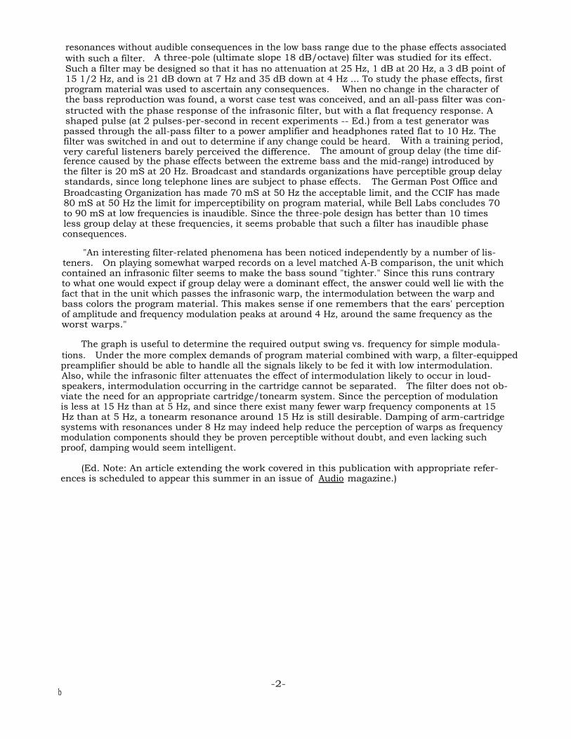
resonances without audible consequences in the low bass range due to the phase effects associatedwith such a filter. A three-pole (ultimate slope 18 dB/octave) filter was studied for its effect.Such a filter may be designed so that it has no attenuation at 25 Hz, 1 dB at 20 Hz, a 3 dB point of15 1/2 Hz, and is 21 dB down at 7 Hz and 35 dB down at 4 Hz ... To study the phase effects, firstprogram material was used to ascertain any consequences. When no change in the character ofthe bass reproduction was found, a worst case test was conceived, and an all-pass filter was con-structed with the phase response of the infrasonic filter, but with a flat frequency response. Ashaped pulse (at 2 pulses-per-second in recent experiments -- Ed.) from a test generator waspassed through the all-pass filter to a power amplifier and headphones rated flat to 10 Hz. Thefilter was switched in and out to determine if any change could be heard. With a training period,very careful listeners barely perceived the difference. The amount of group delay (the time dif-ference caused by the phase effects between the extreme bass and the mid-range) introduced bythe filter is 20 mS at 20 Hz. Broadcast and standards organizations have perceptible group delaystandards, since long telephone lines are subject to phase effects. The German Post Office andBroadcasting Organization has made 70 mS at 50 Hz the acceptable limit, and the CCIF has made80 mS at 50 Hz the limit for imperceptibility on program material, while Bell Labs concludes 70to 90 mS at low frequencies is inaudible. Since the three-pole design has better than 10 timesless group delay at these frequencies, it seems probable that such a filter has inaudible phaseconsequences.
"An interesting filter-related phenomena has been noticed independently by a number of lis-teners. On playing somewhat warped records on a level matched A-B comparison, the unit whichcontained an infrasonic filter seems to make the bass sound "tighter." Since this runs contraryto what one would expect if group delay were a dominant effect, the answer could well lie with thefact that in the unit which passes the infrasonic warp, the intermodulation between the warp andbass colors the program material. This makes sense if one remembers that the ears' perceptionof amplitude and frequency modulation peaks at around 4 Hz, around the same frequency as theworst warps."
The graph is useful to determine the required output swing vs. frequency for simple modula-tions. Under the more complex demands of program material combined with warp, a filter-equippedpreamplifier should be able to handle all the signals likely to be fed it with low intermodulation.Also, while the infrasonic filter attenuates the effect of intermodulation likely to occur in loud-speakers, intermodulation occurring in the cartridge cannot be separated. The filter does not ob-viate the need for an appropriate cartridge/tonearm system. Since the perception of modulationis less at 15 Hz than at 5 Hz, and since there exist many fewer warp frequency components at 15Hz than at 5 Hz, a tonearm resonance around 15 Hz is still desirable. Damping of arm-cartridgesystems with resonances under 8 Hz may indeed help reduce the perception of warps as frequencymodulation components should they be proven perceptible without doubt, and even lacking suchproof, damping would seem intelligent.
(Ed. Note: An article extending the work covered in this publication with appropriate refer-ences is scheduled to appear this summer in an issue of Audio magazine.)
-2-b
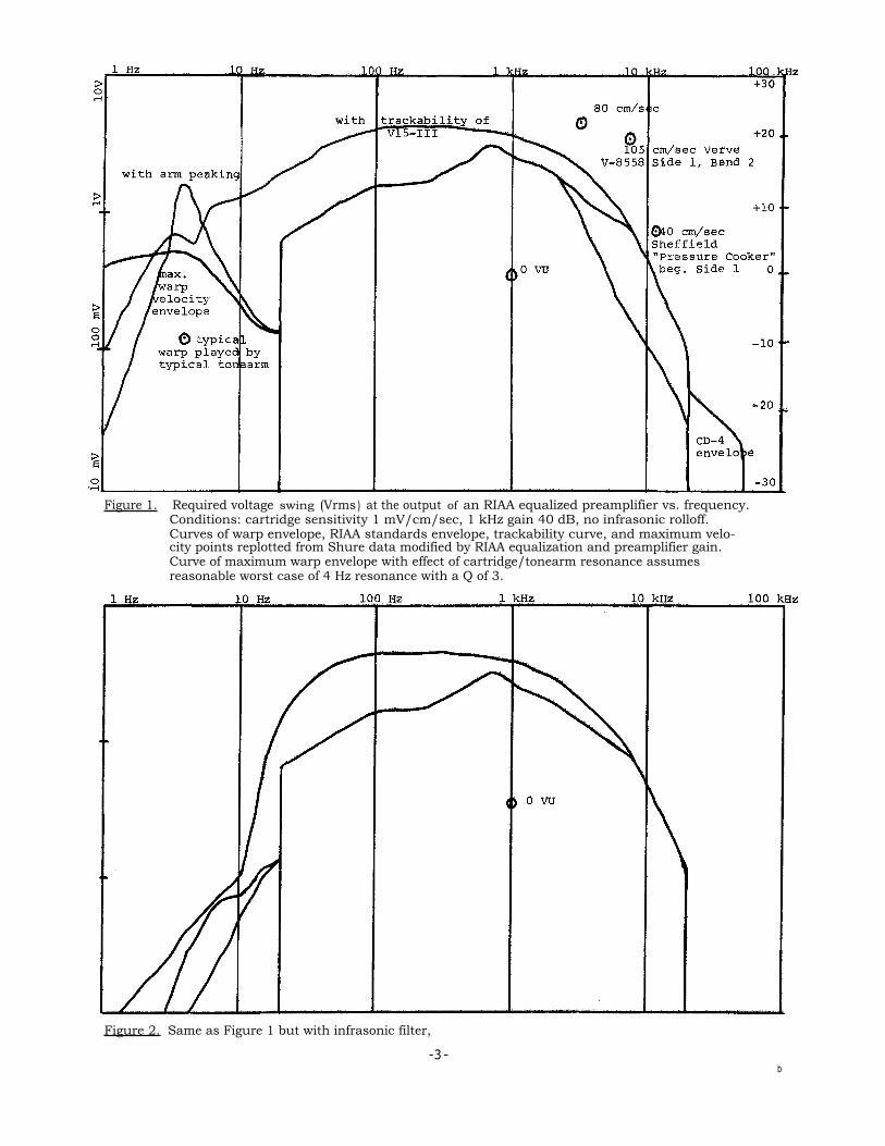
Figure 1. Required voltage swing (Vrms ) at the output of an RIAA equalized preamplifier vs. frequency.Conditions: cartridge sensitivity 1 mV/cm/sec, 1 kHz gain 40 dB, no infrasonic rolloff.Curves of warp envelope, RIAA standards envelope, trackability curve, and maximum velo-city points replotted from Shure data modified by RIAA equalization and preamplifier gain.Curve of maximum warp envelope with effect of cartridge/tonearm resonance assumesreasonable worst case of 4 Hz resonance with a Q of 3.
Figure 2. Same as Figure 1 but with infrasonic filter,
-3-b