the bearing capacity of soils - civilittee-hu.com
TRANSCRIPT

The Bearing Capacity of Soils
Dr Omar Al Hattamleh

Example of Bearing Capacity
Failure • Omar Play the move of bearing Capacity failure The Philippine one
Transcona Grain Silos Failure - Canada

The Bearing Capacity of Soils
• -Terzaghi’s Ultimate Bearing Capacity
• -Meyerhof’s Method
• -Brinch Hansen’ Method
• -Vesic’s Method
• - General Ultimate Bearing Capacity
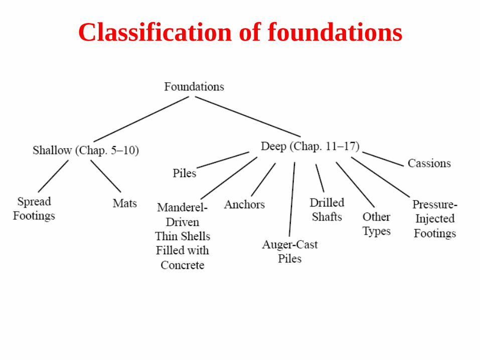
Classification of foundations

Spread footing Shapes & Dimensions

Requirement for Foundation
A shallow foundation must:
1. be safe against an overall shear failure in the soil that supports it.
2. cannot experience excessive displacement (in other words, settlement).
3. cannot experience Excessive Lateral Movement.
The definitions of bearing capacity are,
qo is the contact pressure of the soil at the footing’s invert;
qu is the load per unit area of the foundation at which the shear failure in soil occurs and is called the ultimate bearing capacity of the foundation; and
qall is the load per unit area of the foundation that is supported without an unsafe movement of the soil, and is called the allowable bearing capacity.

Mode of Failure A continuous footing resting on the surface of a dense sand or a stiff cohesive soil is
shown in Figure 2a with a width of B. If a load is gradually applied to the footing, its settlement will increase. When the load per unit area equals qult a sudden failure in the soil supporting the foundation will take place, with the failure surface in the soil extending to the ground surface. This type of sudden failure is called a general shear failure.
If the foundation rests on send or clayey soil of medium compaction (Figure 2b), an increase of load on the foundation will increase the settlement and the failure surface will gradually extend outward from the foundation (as shown by the solid line). When the load per unit area on the foundation equals qult, the foundation movement will be like sudden jerks. A considerable movement of the foundation is required for the failure surface in soil to extend to the ground surface (as shown by the broken lines). The load per unit area at which this happens is the ultimate bearing capacity qult. Beyond this point, an increase of the load will be accompanied by a large increase of footing’s settlement. The load per unit area of the footing qult, is referred to as the first failure load (Vesic 1963). Note that the peak value of q is not realized in this type of failure, which is called the local shear failure in soil.
If the foundation is supported by a fairly loose soil, the load-settlement plot will be like the one in Figure 2c. In this case, the failure surface in soil will not extend to the ground surface. Past the value qult, the load-to-settlement plot will be steep and practically linear. This type of failure is called the punching shear failure.

Modes of bearing capacity failure:

Modes of failure
Based on experimental results from Vesic (1963), a relation for the mode of bearing
capacity failure of foundations can be proposed (Figure 4), where
Dr is the relative density in sand,
Df is the depth of the footing measured from the ground surface,
B is the width and L is the length of the footing (Note: L is always greater than B)

Range of settlement of circular and rectangular plates at ultimate loads for
Df / B = 0 in sand (after Vesic, 1973).
Mode of Failure and Settlement

Terzaghi’s Bearing Capacity Formulas
q

Terzaghi’s Ultimate
Bearing Capacity Theory
Where,
q = Df is the removed pressure from the soil to place the footing
Nc, N, and Nq are the soil-bearing capacity factors, dimensionless terms, whose values relate to the angle of internal friction . These values can be calculated when is known or they can be looked up in Terzaghi’s Bearing Capacity Factor Table 3.1 page 87.
Using an equilibrium analysis, Karl Terzaghi expressed in 1943 the ultimate
bearing capacity qu of a particular soil to be of the form,
(for strip footings, such as wall foundations)
(for square footings, typical of interior columns)
(for circular footings, such as towers, chimneys)
c' = cohesion of soil
= unit weight of soil

Terzaghi’s Ultimate
Bearing Capacity Factors
The bearing capacity factors Nc Nq, and N are defined by (Table 4.1)
Kp=tan2(45+/2)

B.C. Factor of Safety
The factor of safety FS against a bearing capacity failure defined
where qall is the gross allowable load-bearing capacity and qnet is the net ultimate bearing capacity.
The factor of safety is chosen according the function of the structure, but never
less than 3 in all cases.
The net ultimate bearing capacity is defined as the ultimate pressure per unit
area of the footing that can be supported by the soil in excess of the pressure
caused by the surrounding soil at the foundation level.
A footing will obviously not settle at all if the footing is placed at a depth
where the weight of the soil removed is equal to the weight of the
column’s load plus the footing’s weight.
Use qnet instead of qult

Modification of the Bearing Capacity
Equations for the Water Table
Case I: When 0 < D1 < Df .
In term 2 of BC equation
Use ’ in term 3 of BC equation

Modification of the Bearing Capacity
Equations for the Water Table
Case II: When 0 ≤ d ≤ B
B
d)( In term 3 of BC equation
Use in term 2 of BC equation

Modification of the Bearing Capacity
Equations for the Water Table
Case III. When d ≥ B, the water table will have no effect on the ultimate bearing capacity.

The Bearing Capacity for
Local or Punching Shear failure
For the local shear failure Terzaghi proposed
reducing the cohesion and internal friction angle as

Examples (1)
A square foundation is 1.5m x 1.5m in plan. The soil supporting
the foundation has a friction angle of = 20° and c' = 65kPa'. The
unit. weight of soil is 19kN/m3. Determine the allowable gross
load on the foundation with a Factor safety (FS) of 4: Assume that
the depth of the foundation (Df) is 1.5 m and that general shear
failure -occurs in the soil.

Example (2)
Compare Terzaghi bearing capacity equations versus a measured field test that resulted in qu., if L= 5.0 m, c=0, φt = 42.5° and γ’ = 9.31 kN/m2.

General Bearing
Capacity Equation

The General Bearing Capacity Equation. The Terzaghi ultimate bearing capacity equations presented previously are for
continuous, square, and circular footings only. They do not include rectangular footings (0 < B/L < 1), or take into account the shearing resistance along the failure surface in the soil above the bottom of the foundation, or the inclination of the footing or the load (Hansen, 1970)
Where
c = the cohesion;
q = the excavated soil’s pressure at the footing’s invert (its bottom);
= the unit weight of the soil;
B = width of foundation ( equal to the diameter for a circular foundation);
Nc, Nq, N are the bearing capacity factors;
Fcs, Fqs, F s are the shape factors;
Fcd, Fqd, Fd are the depth factors; and
Fci, Fqi, F i are the load inclination factors.

bearing capacity factors
(Table 4.2)

Shape and Depth, and Inclination Factors

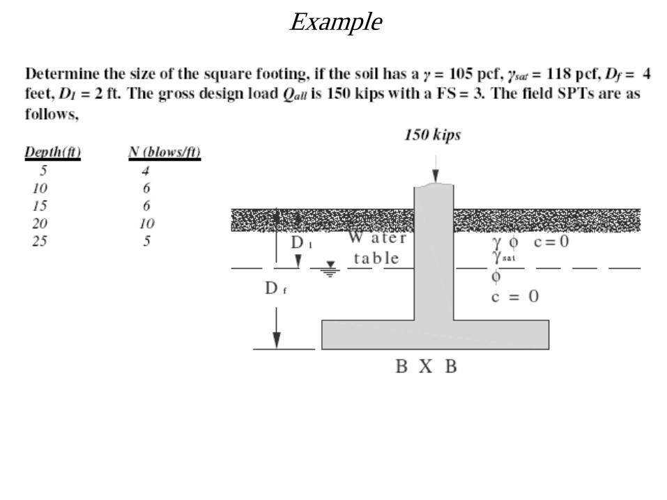
Example
A square foundation (B x B) has to be constructed as shown in Figure assume that = 17kN/m3, sat = 19.5 kN/m3, D1 = 0.75m, and Df = 1.2m. The gross design allowable load, Qall, with FS = 3 is 60 kN. The SPT values are
Depth
(m)
N60
(Blows/ft)
1.0 4
1.5 6
3.0 10
4.0 5

Bearing Capacity of Soils
on Eccentrically Loaded Footings Foundations with a One-Way Eccentricity.
In most instances, foundations are subjected to moments in addition to the vertical load as shown below.
In such cases the distribution of pressure by the foundation upon the soil is not uniform.
The effective width is
now,
B’ = B - 2e
whereas the effective
length is Still,
L’ = L

The distribution of the nominal (contact) pressure
where Q is the total vertical load and M is the moment
on the footing in one axis.
Substituting equation in equations above Eqs. yields:

Notes
• Note that in these equations,
– when the eccentricity e becomes B/6, qmin is zero.
– For e >B/6, qmin will be negative, which means that tension
will develop. Because soils can sustain very little tension,
there will be a separation between the footing and the soil
under it.
– The value of qmax is then
• Also note that the eccentricity tends to decrease the
load bearing capacity of a foundation.

Foundations with Two-way Eccentricities
Consider a footing subject to a vertical ultimate load Qult and a moment M as shown in Figures. For this case, the components of the moment M about the x and y axis are Mx and My respectively. This condition is equivalent to a load Q placed eccentrically on the footing with x = eB and y = eL

Modification for General Bearing Capacity
The general bearing capacity equation is therefore modified to,
As before, to evaluate Fcs , Fqs , and Fs , use the effective
length (L') and the effective width (B') dimensions instead of L
and B, respectively.
To calculate Fcd , Fqd , and Fd and ,do not replace B with B'.
The factor of safety against bearing capacity failure is FS
=Qult/Q
Check the factor of safety against qmax or FS = qu/qmax
Finally note we confine here our self to eL L/6 or eBB/6

Example
A square footing is 1.8 X 1.8 m with a 0.4 X 0.4 m square column. It is loaded with an axial load of 1800 kN and Mx = 450 kN • m; My = 360 kN • m. Undrained triaxial tests (soil not saturated) give ’ = 36° and c = 20 kPa. The footing depth D = 1.8 m; the soil unit weight y = 18.00 kN/m3; the water table is at a depth of 6.1 m from the ground surface.

Bearing Capacity For Footings
On Layered Soils
• There are three general cases of the footing on
a layered soil as follows:
Case 1. Footing on layered clays (all = 0) as in Fig..
a. Top layer weaker than lower layer (c1 < c2)
b. Top layer stronger than lower layer (c1 > c2)
Case 2. Footing on layered -c soils with a, b same as case 1.
Case 3. Footing on layered sand and clay soils as in Fig.
a. Sand overlying clay
b. Clay overlying sand

Stronger Soil Is Underlain By A Weaker Soil -1
If H, the thickness of the layer of soil below the
footing, is relatively large then the failure surface
will be completely located in the top soil layer,
which is the upper limit for the ultimate bearing
capacity.
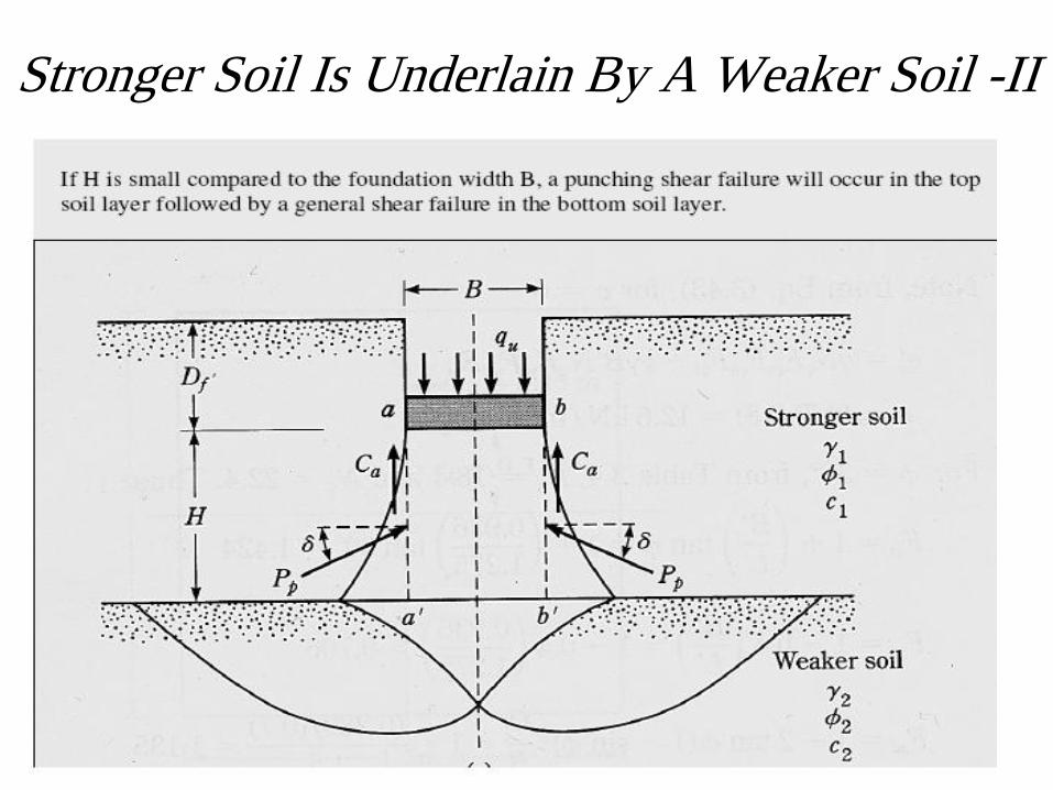
Stronger Soil Is Underlain By A Weaker Soil -II

In this condition, where the stronger surface soil is underlain by
a weaker stratum, the general Bearing capacity equation is
modified to,
where, ca is the adhesion, Ks is the punching shear coefficient, qt is
the bearing capacity of the top soil layer, qb is the bearing capacity
of the bottom soil layer, H is the height of top layer, 1 is the angle
of internal friction of top soil and 2 for the bottom soil.

Ca determination

punching shear coefficient Ks

Example
A foundation 1.5 m by 1 m is placed at a depth of 1 m in a stiff clay. A softer clay layer is located at a depth of 1 m measured from the bottom of the foundation. For the top layer, the un-drained shear strength is 120 kN/m2, the unit weight is 16.8 kN/m2, and for the bottom layer the un-drained shear strength is 48 kN/m2, and the unit weight is 16.2 kN/m2. Find the allowable bearing capacity for this footing.

The Other Cases
1. The top layer is strong, and the bottom layer is a saturated soft clay ( = 0);
2. The top layer is stronger sand and the bottom layer is a weaker sand (c1 = 0) (c2 = 0);
3. The top layer is a stronger saturated clay (1 = 0), and the bottom layer is weaker saturated clay (2 = 0).
Use the same method before
and apply corrections were needed

Bearing Capacity From SPT
• Two Ways:
1. Using the correlation to find ’and using the
general bearing capacity equation
2. Using the following chart (for surface footing)

Bearing Capacity From SPT
Allowable
bearing capacity
for surface-
loaded footings
with settlement
limited to
approximately 25
mm.

Bearing Capacity From SPT
)4.25
S(FN16.19q a
d60)all(net For B≤1.22 m
)4.25
S(F)
B28.3
1B28.3(N98.11q a
d2
60)all(net
For B≥1.22 m
Where
qnet(all)= qall-Df kN/m2
Sa: tolerable settlement in mm
Fd=depth factor=1+0.33(Df/B)≤1.33
Bearing Capacity Using The Cone Penetration Test (CPT)
)15
q(q c
)all(net For B≤1.22 m
2c)all(net )
B28.3
1B28.3)(
25
q(q
For B≥1.22 m
Where
qnet(all)= qall-Df kN/m2
Example

The Bearing Capacity
of
Mat Foundations


Compensation Mat Foundation

Bearing Capacity for Field Load Tests

Bearing Capacity Based On Building Codes
(Presumptive Pressure)

Safety Factors In Foundation Design
There are more uncertainties in determining the allowable strength of the soil than in the superstructure elements. These may be summarized as follows:
• Complexity of soil behavior
• Lack of control over environmental changes after construction
• Incomplete knowledge of subsurface conditions
• Inability to develop a good mathematical model for the foundation
• Inability to determine the soil parameters accurately

Safety Factors In Foundation Design
These uncertainties and resulting approximations have to be evaluated for each site and a suitable safety factor directly (or indirectly) assigned that is not overly conservative but that takes into account at least the following:
1. Magnitude of damages (loss of life, property damage, and lawsuits) if a failure results
2. Relative cost of increasing or decreasing SF
3. Relative change in probability of failure by changing SF
4. Reliability of soil data
5. Changes in soil properties from construction operations, and later from any other causes
6. Accuracy of currently used design/analysis methods

Safety Factors Usually Used
• Values of stability numbers (or safety factors) usually used
• It is customary to use overall safety factors on the order of those shown in Table. Shear should be interpreted as bearing capacity for footings.

Bearing Capacity Of Rock

References
1. J. Bowles, “Foundation Analysis and
Design”, McGraw-Hill;
2. B. Das, “Principles of foundation
Engineering”, Thompson;
3. Coduto, “Foundations Design”, Prentice
Hall;