the bending of beams and the second moment of area
TRANSCRIPT

University of Plymouth
PEARL https://pearl.plymouth.ac.uk
The Plymouth Student Scientist - Volume 06 - 2013 The Plymouth Student Scientist - Volume 6, No. 2 - 2013
2013
The bending of beams and the second
moment of area
Bailey, C.
Bailey, C., Bull, T., and Lawrence, A. (2013) 'The bending of beams and the second moment of
area', The Plymouth Student Scientist, 6(2), p. 328-339.
http://hdl.handle.net/10026.1/14043
The Plymouth Student Scientist
University of Plymouth
All content in PEARL is protected by copyright law. Author manuscripts are made available in accordance with
publisher policies. Please cite only the published version using the details provided on the item record or
document. In the absence of an open licence (e.g. Creative Commons), permissions for further reuse of content
should be sought from the publisher or author.

The Plymouth Student Scientist, 2013, 6, (2), p. 328–339
The Bending of Beams and the SecondMoment of Area
Chris Bailey, Tim Bull and Aaron Lawrence
Project Advisor: Tom Heinzl, School of Computing and Mathematics, PlymouthUniversity, Drake Circus, Plymouth, PL4 8AA
AbstractWe present an overview of the laws governing the bending of beams and of beamtheory. Particular emphasis is put on beam stiffness associated with different crosssection shapes using the concept of the second moment of area.
[328]

The Plymouth Student Scientist, 2013, 6, (2), p. 328–339
1 Historical Introduction
Beams are an integral part of everyday life, with beam theory involved in the develop-ment of many modern structures. Early applications of beam practice to large scaledevelopments include the Eiffel Tower and the Ferris Wheel. Beam theory also wascrucial for the Second Industrial Revolution [1].
The theory of beams has a long history. It was believed that Galileo Galilei madethe initial attempts at a theory, but then, in 1967, came the discovery of The CodexMadrid. This document is written proof that Leonardo da Vinci’s published work of1493 had not only preceded Galileo’s by over 100 years, but also represented animprovement. Unlike Galileo, da Vinci correctly identified the stress and strain distri-bution across a section in bending. Even with this accurate identification, there wasstill no mention of assessing the strength of a beam once the dimensions are known,and the tensile strength of the material it was made of [2].
This was addressed by Galileo, but due to some incorrect assumptions, Galileo’sresult was three times larger than the correct value, so it needed considerable im-provement. Alternative approaches were published in 1686 and 1713 by Edme Mari-otte and Antoine Parent, respectively, but both did not have a serious impact [2].
The major breakthrough came when Daniel Bernoulli and Leonard Euler adaptedwork previously attempted by Daniel’s uncle, Jacob Bernoulli, into what is now knownas the Euler-Bernoulli Beam Theory. Daniel Bernoulli suggested to Euler that heshould apply variational calculus when deriving the differential equations of elasticcurves, which he then integrated to obtain the formula for the deflection d of the endof a cantilever,
d =PL2
3C. (1)
The constant C is called the absolute elasticity and P is the load placed on the can-tilever of length L. Bernoulli was also the first to derive the differential equation govern-ing lateral vibrations of prismatic bars, and he made a series of verifying experiments.Euler also considered the buckling of straight bars under axial load, and derived theequation
P =Cπ2
4l2, (2)
where l denotes the position of the load on the beam. He also successfully derivedequations for the vibration of beams.
By 1750, Euler had derived many equations for Beam Theory, including thosestated above, and his methods could also be extended to the calculation of bendingstresses, and hence the bending capacity of beams made of brittle materials [3].
Despite all the work by Euler and Bernoulli, they still did not take into accountshear deformation, where the beam changes in shape but not in length, and rotationalinertia effects, a property of rotating bodies that defines its resistance to a change inangular velocity about an axis of rotation [4]. This was eventually covered by the Tim-oshenko Beam Theory, developed by Ukrainian-born scientist and engineer Stephen
[329]

The Plymouth Student Scientist, 2013, 6, (2), p. 328–339
Timoshenko early in the 20th century [5]. His advanced theory, however, is beyondthe scope of this short overview.
2 Laws Governing the Bending of Beams
2.1 Euler-Bernoulli
The Euler-Bernoulli beam theory is the most widely used theory and can be derivedfrom four key principles [6]. These are: kinematics, the constitutive law, resultantsand the equilibrium law. By looking at these in detail, we can see exactly how theEuler-Bernoulli beam theory is derived.
2.1.1 Kinematics
This is the method used to measure the displacement of a bending beam from itsinitial starting place at any given moment in time.
θ
Undeformed State
Deformed State y
xyu
w
x
Figure 1: Initial kinematics of a bending beam [7].
In Figure 1 pressure is being applied on the bottom side of the beam. w repre-sents the centre of the beam and θ the angle of rotation of the neutral plane. Similarlyχ represents the rotation of the beam’s cross section; this is what we want to calcu-late. u is the displacement of the cross section with respect to the x-axis. Note thatwe are only considering the beam to bend in the x-axis, and so y is not important forus in this case. A way to model the beam is to consider it being composed of fibres.When the beam bends, the side with the force being exerted on will contract whilst, to
[330]

The Plymouth Student Scientist, 2013, 6, (2), p. 328–339
compensate, the opposite side of the beam elongates. To model this we consider thestrain throughout the entire beam to balance the fact that some parts may contractmore than others elongate. Hence we model the strain ε as
ε =dudx
. (3)
Continuing to model only with respect to x , we follow Kirchhoff’s assumptions thatbeam normals remain straight, unstretched and at right angles to the normal plane.
From the third of these assumptions, we see that displacement u and rotationangle χ are related as
u(x , y ) = χ(x)y , (4)
so that the strain (3) becomes
ε =dχ
dxy (5)
On the other hand, by the definition of the derivative, we have that
χ = −θ = −dwdx
(6)
From (5) and (6), we can write ε in the form
ε = −d2w
dx2y (7)
2.1.2 Constitutive Law
The constitutive law provides a relation between direct stress and strain (σ and ε,respectively) within the beam. “Direct” here means normal to the cross section ofthe beam. In general, direct stress will be distributed across the beam cross section(chosen to be the yz plane) as shown in Figure 2, so σ = σ(x , y ).
),( yx
x
y
Figure 2: Direct stress distribution across a beam [8].
[331]

The Plymouth Student Scientist, 2013, 6, (2), p. 328–339
Young’s elastic modulus, E , is a material constant characterising the elasticity ofa given material. Mathematically, it is the constant of proportionality relating directstress and strain in Hooke’s law, which in our case reads [8]:
σ(x , y ) = Eε(x , y ) . (8)
In addition to direct or normal stress σ, there is also shear stress σxy to be taken intoaccount. The latter acts tangentially to surfaces (see Figure 3).
),( yxxy
x
y
Figure 3: Shear stress distribution across a beam [9].
2.1.3 Resultants
Given the distributions of direct and shear stress we can form moments by integra-tion. These are commonly referred to as resultants. Two important examples are themoment resultant obtained from direct stress,
M(x) =
∫ ∫yσ(x , y )dydz , (9)
and the force resultant, the area integral of shear stress,
V (x) =
∫ ∫σxy (x , y )dydz . (10)
2.1.4 Equilibrium
Given any section of a beam we choose to work with we can now trade the stressesin both coordinate directions for the resultant forces to eliminate the dependence onthe y coordinate.
Taking the derivatives of (9) and (10) with respect to the remaining variable x wefind the equilibrium equations
dVdx
= −p , (11)
[332]
The Plymouth Student Scientist, 2013, 6, (2), p. 328–339
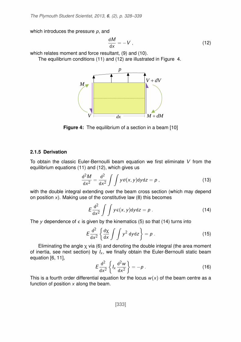
which introduces the pressure p, and
dMdx
= −V , (12)
which relates moment and force resultant, (9) and (10).The equilibrium conditions (11) and (12) are illustrated in Figure 4.
dVV
dMM dx
M
V
p
Figure 4: The equilibrium of a section in a beam [10]
2.1.5 Derivation
To obtain the classic Euler-Bernoulli beam equation we first eliminate V from theequilibrium equations (11) and (12), which gives us
d2M
dx2=
d2
dx2
∫ ∫yσ(x , y )dydz = p , (13)
with the double integral extending over the beam cross section (which may dependon position x). Making use of the constitutive law (8) this becomes
Ed2
dx2
∫ ∫yε(x , y )dydz = p . (14)
The y dependence of ε is given by the kinematics (5) so that (14) turns into
Ed2
dx2
{dχ
dx
∫ ∫y2 dydz
}= p . (15)
Eliminating the angle χ via (6) and denoting the double integral (the area momentof inertia, see next section) by Ix , we finally obtain the Euler-Bernoulli static beamequation [6, 11],
Ed2
dx2
{Ix
d2w
dx2
}= −p . (16)
This is a fourth order differential equation for the locus w (x) of the beam centre as afunction of position x along the beam.
[333]

The Plymouth Student Scientist, 2013, 6, (2), p. 328–339
3 Beam Stiffness
In this section we compare the stiffness of beams with different cross sections. Clearly,the shape of a beam’s cross section is fundamental in determining how much thebeam will deflect under load. The mathematics relating to this deflection is presentedthrough the concept of the ‘second moment of area’. This can be calculated for dif-ferent beam cross sections to obtain an idea of the rigidity. We have chosen twocommon beam cross section shapes, and we discuss the stiffness of each one. Fi-nally, we will be able to make a decision as to which shape would be more resistantto bending at a certain cross sectional area.
3.1 Second Moment of Area
The second moment of area is known by several different names, including the areamoment of inertia, the moment of inertia of plane area and the second moment ofinertia. It is a property of a cross section that can be used to predict the resistance ofbeams to bending and deflection. The deflection of a beam under load depends notonly on the load, but also on the geometry of the beam’s cross section. The secondmoment of area has units of length to the fourth power and, therefore, has SI unitsof m4. Beams with a large second moment of area are more resistant to bending, soare stiffer than those with a small second moment of area. This is why beams with ahigher second moment of area, such as I-beams, are often seen in the constructionof buildings. The second moment of area is calculated using the following equations[12],
Ix =
∫y2dA , (17)
Iy =
∫x2dA , (18)
where x and y are the coordinates of an infinitesimal area element dA, as seen inFigure 5. When using these equations it is important to note that the cross sectionalarea is parallel to the xy plane while the z-axis runs along the length of the beambeing bent. Typically the beam is loaded along the z-axis with the forces acting inthe vertical direction, along the y -axis. With this type of loading, the second momentof area about the x-axis is required; therefore the formula for Ix should be used.Sometimes a beam may be loaded laterally with loads parallel to the x-axis. In thiscase, the formula for Iy should be used to find the second moment of area about they -axis.
3.2 Beam Cross Sections
Having defined the crucial factors associated with beam stiffness and the mathe-matical method used to rate a beam’s deflection under load, we can look into some
[334]

The Plymouth Student Scientist, 2013, 6, (2), p. 328–339
dA
b
h
y
x
Figure 5: Rectangular beam cross section centred at the origin with height, h andwidth, b.
common beam cross sectional shapes.
3.2.1 Solid Square Cross Section
An extremely common cross sectional shape for a beam is a solid square or, thegeometrically similar, rectangle. This is possibly the simplest beam to manufactureand provides many uses at a relatively low cost. We want to address the stiffnessassociated with this beam shape. As explained before, we can do this by looking atthe second moment of area. Figure 5, shows the position of a rectangle, centred atthe origin, with the horizontal x-axis and vertical y -axis running through the middle ofthe shape [13]. Clearly, for a square cross section the height, h, would be equal tothe width, b.
We want to find out how the cross sectional area affects the deflection in the y -direction as a load is applied along the z-axis with the force in the vertical direction.We therefore need formula (17) for Ix . Then, choosing the appropriate integrationlimits and identifying dA = dxdy , we have
Ix =
∫y2dA =
h/2∫−h/2
y2dy
b/2∫−b/2
dx =bh3
12. (19)
[335]

The Plymouth Student Scientist, 2013, 6, (2), p. 328–339
This is the equation for the second moment of area for a beam with a solid rectangularcross section. As expected, it is dependent on the height, h and the width, b. Thisalso leads to the formula for the second moment of area of a beam with a squarecross section by setting the dimensions h and b equal to each other. Straight away,we can draw an obvious conclusion: a beam with a large rectangular cross sectionalarea (i.e. large h and b) will have a higher second moment of area and will thereforebe stiffer than a beam with a small rectangular cross sectional area. As the heightis the dominant term in the formula, we can see that varying this will have a greaterimpact on the value of the second moment of area.
3.2.2 Solid Circular Cross Section
We now move on to look at a beam with a different cross sectional shape, a circle.Again, we can use the concept of the second moment of area to gain an idea ofthe stiffness achieved by using a circular beam. Using this, we want to compare thestiffness of beams with the same cross sectional areas but one of a square crosssection, the other with a circular. The circle is centred about the origin with radius, a,as shown in Figure 6.
dθ
a
dA
y
x
Figure 6: Circular beam cross section with radius a. Also shows the element dA.
Again, we are looking at the deflection in the vertical direction so need the Ix from(17). As we are dealing with a circle it is easier to calculate the integral using polarcoordinates where the surface element is dA = rdrdθ (cf. Figure 6), and y = r sinθ.
[336]

The Plymouth Student Scientist, 2013, 6, (2), p. 328–339
Armed with this information we are able to tackle the integral,
Ix =
∫y2dA =
2π∫0
sin2 θdθ
a∫0
r3dr =r4π4
. (20)
The second moment of area, on its own, does not provide too much information, onlythat a thicker beam will result in a higher second moment of area and therefore ismore resistant to bending. This is obvious in day to day life. The real power of areamoments shows up in the comparison of different cross sectional shapes.
3.3 Square and Circular Beam Cross Sections: Comparison
As stated, to determine which cross sectional shape beam provides more resistanceto bending, the values of the second moment of area need to be compared. So farin this section we have derived the formulae for calculating the second moment ofarea for a beam with a solid square or rectangular cross section and a beam with asolid circular cross section. We now want to determine which of these shapes gives astiffer beam at a given cross sectional area, A = b2. The respective second momentsof area are
I� =b2
12=
A2
12, (21)
I◦ =r4π12
=A2
4π< I� , (22)
the latter inequality following from 4π > 12. Thus, we can clearly see that the secondmoment of area for a beam with a circular cross section is slightly smaller than thatof a beam with a square cross section of the same area, the relative difference beingabout 5 %. Therefore, the square beam provides slightly more resistance to bendingthan the circular one. This shows how engineers can straightforwardly compare therigidity of beams with various cross sections.
4 Discussion and Conclusion
As we have seen, the derivation of the Euler-Bernoulli beam theory from initial prin-ciples provides an accurate representation of the pressure on a static beam givenits elasticity, length and position. Timoshenko then improved on this, with the con-sideration of shear deformation and rotational inertia effects. For the Euler-Bernoullibeam theory, inertia (the second moment of area) plays a key role. Its main ingredi-ent is the cross sectional shape of the beam. We have shown mathematically that asquare cross section provides more resistance to bending than a circular one. Thisis unsurprising as rectangular shapes are the more popular choice in construction if
[337]

The Plymouth Student Scientist, 2013, 6, (2), p. 328–339
a lateral load is to be held (Fig. 7). The general rule for increasing rigidity is to makethe area moments large. This can be done most elegantly (keeping beam weightwithin reasonable limits) by having cross sectional area concentrated away from thebeam centre. The next logical step would thus be to look at more complicated crosssections used in construction, such as hollow beams, I-beams or T-sections.
Figure 7: A typical use of square beams [14].
References
[1] http://en.wikipedia.org/wiki/Euler-Bernoulli beam theory, accessed 20-01-2013.
[2] http://newtonexcelbach.wordpress.com/2008/02/27/the-history-of-the-theory-of-beam-bending-part-1/, accessed 20-01-2013.
[3] http://newtonexcelbach.wordpress.com/2008/07/12/the-history-of-the-theory-of-beam-bending-part-3/, accessed 20-01-2013.
[4] http://en.wikipedia.org/wiki/Moment of inertia, accessed 20-01-2013.
[5] http://en.wikipedia.org/wiki/Timoshenko beam theory, accessed 20-01-2013.
[6] http://www.efunda.com/formulae/solid mechanics/beams/theory.cfm, accessed20-01-2013.
[7] http://www.efunda.com/formulae/solid mechanics/beams/theory kinematics.cfm,accessed 20-01-2013.
[8] http://www.efunda.com/formulae/solid mechanics/beams/theory constitutive.cfm,accessed 20-01-2013.
[338]
The Plymouth Student Scientist, 2013, 6, (2), p. 328–339
[9] http://www.efunda.com/formulae/solid mechanics/beams/theory resultants.cfm,accessed 20-01-2013.
[10] http://www.efunda.com/formulae/solid mechanics/beams/theory equilibrium.cfm,accessed 20-01-2013.
[11] P. K. Kythe and D. Wei, An Introduction to Linear and Nonlinear Finite ElementAnalysis: A Computational Approach, Springer, 2004.
[12] http://efunda.com/math/areas/IndexArea.cfm, accessed 20-01-2013.
[13] http://youtube.com/watch?v=QR5mivx0xc0, accessed 20-01-2013.
[14] http://images01.olx.com/ui/10/41/83/1292201702 146163883 8-Reclaimed-Barn-Beams-by-JLT-Millworks-Lumber-Jane-Janice-Tupper–1292201702.jpg,accessed 20-01-2013.
[339]