the brain opera technology: new instruments and … · music interfaces, interactive music ... some...
TRANSCRIPT
The Brain Opera Technology: NewInstruments and Gestural Sensors forMusical Interaction and Performance
Joseph A. Paradiso
MIT Media Laboratory E15-325Cambridge MA 02139 USA
Tel: +1-617-253-8988Fax: +1-617-258-7168
Keywords: Brain Opera, human-computer interface, multimodal input devices, electronicmusic interfaces, interactive music systems, percussion interfaces, interactive dance,electric field sensing, capacitive sensing
ABSTRACT
This paper describes the array of new musical instruments and interactive installations
developed for the Brain Opera, a large, touring multimedia production, where the audience
first explores a set of musical modes at a variety of novel, interactive stations before
experiencing them in an actual performance. Most of the Brain Opera's installations were
intended for the general public, employing different gestural measurements and mappings
that allow an untrained audience to intuitively interact with music and graphics at various
levels of complexity. Another set of instruments was designed for a trio of trained
musicians, who used more deliberate technique to perform the composed music. This
paper outlines the hardware and sensor systems behind these devices: the electric field
sensors of the Gesture Wall and Sensor Chair, the smart piezoelectric touchpads of the
Rhythm Tree, the instrumented springs in Harmonic Driving, the pressure-sensitive touch
screens of the Melody Easels, and the multimodal Digital Baton, containing a tactile
interface, inertial sensors, and precise optical tracker. Also discussed are a set of
controllers developed for the Brain Opera, but not currently touring with the production,
including the Magic Carpet (immersive body sensing with a smart floor and Doppler radar)
and an 8-channel MIDI-controlled sonar rangefinder.
____________________________________________________________________________________
Version 2.0, November 1998; To appear in the Journal of New Music Research
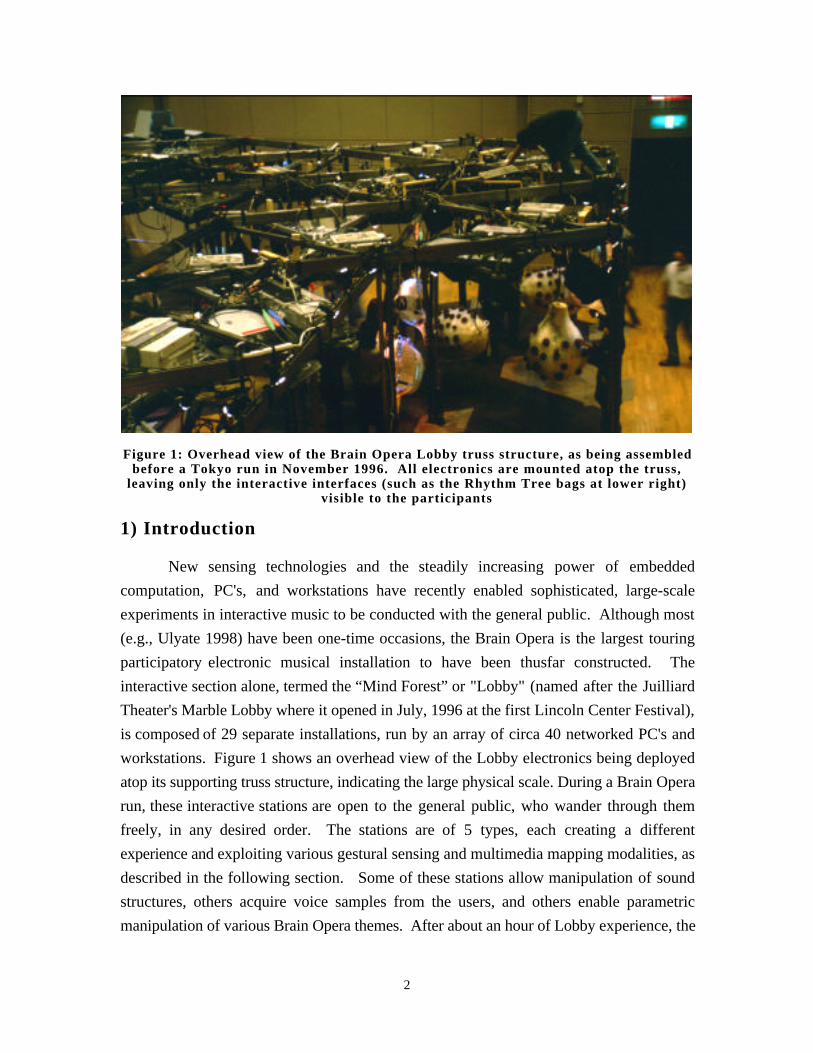
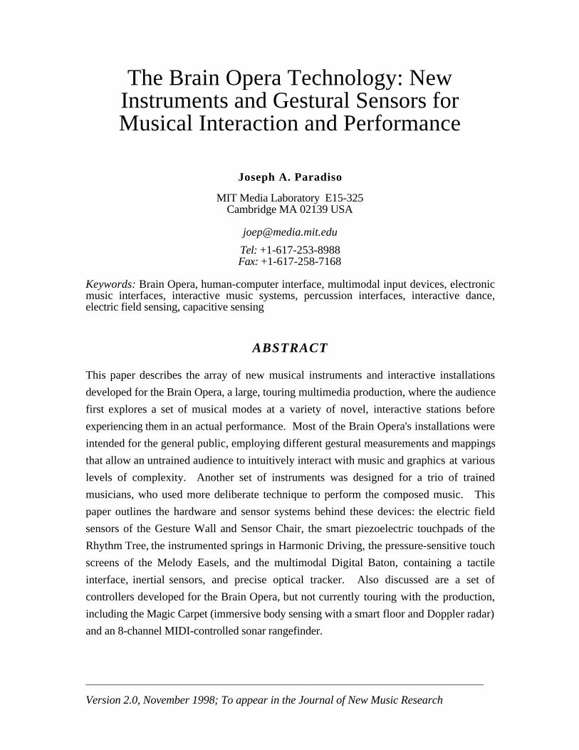
Figure 1: Overhead view of the Brain Opera Lobby truss structure, as being assembledbefore a Tokyo run in November 1996. All electronics are mounted atop the truss,
leaving only the interactive interfaces (such as the Rhythm Tree bags at lower right)visible to the participants
1) Introduction
New sensing technologies and the steadily increasing power of embedded
computation, PC's, and workstations have recently enabled sophisticated, large-scale
experiments in interactive music to be conducted with the general public. Although most
(e.g., Ulyate 1998) have been one-time occasions, the Brain Opera is the largest touring
participatory electronic musical installation to have been thusfar constructed. The
interactive section alone, termed the “Mind Forest” or "Lobby" (named after the Juilliard
Theater's Marble Lobby where it opened in July, 1996 at the first Lincoln Center Festival),
is composed of 29 separate installations, run by an array of circa 40 networked PC's and
workstations. Figure 1 shows an overhead view of the Lobby electronics being deployed
atop its supporting truss structure, indicating the large physical scale. During a Brain Opera
run, these interactive stations are open to the general public, who wander through them
freely, in any desired order. The stations are of 5 types, each creating a different
experience and exploiting various gestural sensing and multimedia mapping modalities, as
described in the following section. Some of these stations allow manipulation of sound
structures, others acquire voice samples from the users, and others enable parametric
manipulation of various Brain Opera themes. After about an hour of Lobby experience, the
2
audience is conducted into a theater space, where a trio of musicians performs the entire
Brain Opera composition on a set of “hyperinstruments” (Machover 1991), similar in style
and technology to those previously experienced in the Lobby.
The Brain Opera, conceived and directed by Tod Machover, was designed and
constructed by a highly interdisciplinary team at the MIT Media Laboratory during an
intensive effort from the fall of 1995 through summer of 1996. A major artistic goal of this
project was to integrate diverse, often unconnected control inputs and sound sources from
the different Lobby participants into a coherent artistic experience that is "more than the
sum of its parts", inspired by the way our minds congeal fragmented experiences into
rational thought (Machover 1996). This congealing process was anticipated to culminate in
the Brain Opera performance, where the diverse themes and activities experienced in the
Lobby were actively sculpted into a succinct musical piece. Such analogies to brains and
the thought process, particularly as interpreted by artificial intelligence pioneer Marvin
Minsky (Minsky 1988), drove much of the initial Brain Opera inspiration, from the use of
uncorrelated, essentially stochastic audience input (emulating neural stimulation) to the
somewhat "biological" appearance of the physical set. More generally, the Brain Opera
attempts to make a strong statement about actively involving non-specialized audiences in
artistic environments, confronting many questions about interactive music to which ready
answers are currently lacking (Machover 1996).
The overall design of the Brain Opera as an interactive installation is described in
(Orth 1997), and its artistic motivation and goals have been discussed in many articles;
e.g., (Machover 1996), (Rothstein 1996), (Wilkinson 1997). This paper, in contrast,
concentrates on the many different instruments and interactive stations developed for this
project, describing their technical design, sensor architectures, and functional performance.
The Brain Opera is by no means a fixed or purely experimental installation; it had to
operate in many real-world environments (already having appeared at 7 international
venues), and function with people of all sizes, ages, cultures, and experience levels. As a
result, the interface technologies were chosen for their intuitiveness, overall robustness and
lack of sensitivity to changing background conditions, noise, and clutter. This tended to
rule out computation-intensive approaches, such as computer vision (e.g., Wren et. al.
1997), which, although improving in performance, would be unable to function adequately
in the very dense and dynamic Brain Opera environment.
Most of the Brain Opera's software is run on IBM PCs under Windows 95 or NT
using ROGUS (Denckla and Pelletier 1996), a C++ MIDI utility library developed for this
project, although some of the performance instruments are based around Apple
Macintoshes running vintage code written in Hyperlisp (Chung 1988). Most of the musical
3
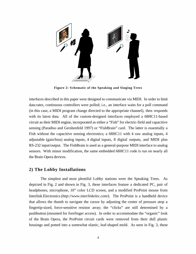
Figure 2: Schematic of the Speaking and Singing Trees
interfaces described in this paper were designed to communicate via MIDI. In order to limit
data rates, continuous controllers were polled; i.e., an interface waits for a poll command
(in this case, a MIDI program change directed to the appropriate channel), then responds
with its latest data. All of the custom-designed interfaces employed a 68HC11-based
circuit as their MIDI engine, incorporated as either a “Fish” for electric-field and capacitive
sensing (Paradiso and Gershenfeld 1997) or “FishBrain” card. The latter is essentially a
Fish without the capacitive sensing electronics; a 68HC11 with 4 raw analog inputs, 4
adjustable (gain/bias) analog inputs, 4 digital inputs, 8 digital outputs, and MIDI plus
RS-232 input/output. The FishBrain is used as a general-purpose MIDI interface to analog
sensors. With minor modification, the same embedded 68HC11 code is run on nearly all
the Brain Opera devices.
2) The Lobby Installations
The simplest and most plentiful Lobby stations were the Speaking Trees. As
depicted in Fig. 2 and shown in Fig. 3, these interfaces feature a dedicated PC, pair of
headphones, microphone, 10” color LCD screen, and a modified ProPoint mouse from
Interlink Electronics (http://www.interlinkelec.com/). The ProPoint is a handheld device
that allows the thumb to navigate the cursor by adjusting the center of pressure atop a
fingertip-sized, force-sensitive resistor array; the “clicks” are still determined by a
pushbutton (mounted for forefinger access). In order to accommodate the “organic” look
of the Brain Opera, the ProPoint circuit cards were removed from their dull plastic
housings and potted into a somewhat elastic, leaf-shaped mold. As seen in Fig. 3, these
4
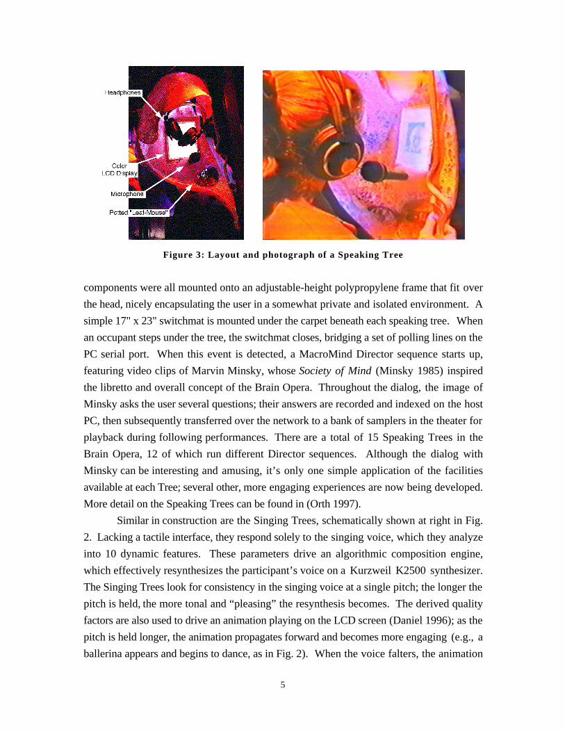
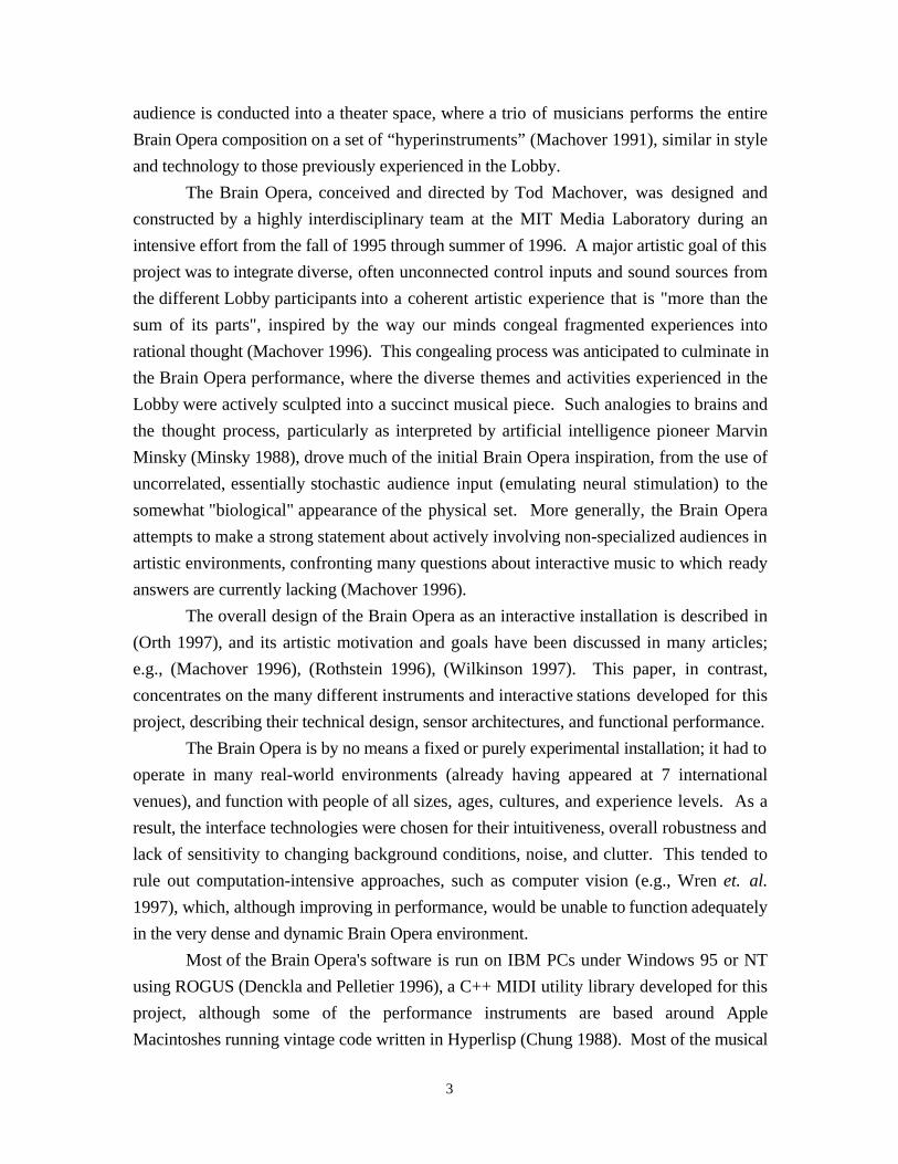
Figure 3: Layout and photograph of a Speaking Tree
components were all mounted onto an adjustable-height polypropylene frame that fit over
the head, nicely encapsulating the user in a somewhat private and isolated environment. A
simple 17" x 23" switchmat is mounted under the carpet beneath each speaking tree. When
an occupant steps under the tree, the switchmat closes, bridging a set of polling lines on the
PC serial port. When this event is detected, a MacroMind Director sequence starts up,
featuring video clips of Marvin Minsky, whose Society of Mind (Minsky 1985) inspired
the libretto and overall concept of the Brain Opera. Throughout the dialog, the image of
Minsky asks the user several questions; their answers are recorded and indexed on the host
PC, then subsequently transferred over the network to a bank of samplers in the theater for
playback during following performances. There are a total of 15 Speaking Trees in the
Brain Opera, 12 of which run different Director sequences. Although the dialog with
Minsky can be interesting and amusing, it’s only one simple application of the facilities
available at each Tree; several other, more engaging experiences are now being developed.
More detail on the Speaking Trees can be found in (Orth 1997).
Similar in construction are the Singing Trees, schematically shown at right in Fig.
2. Lacking a tactile interface, they respond solely to the singing voice, which they analyze
into 10 dynamic features. These parameters drive an algorithmic composition engine,
which effectively resynthesizes the participant’s voice on a Kurzweil K2500 synthesizer.
The Singing Trees look for consistency in the singing voice at a single pitch; the longer the
pitch is held, the more tonal and “pleasing” the resynthesis becomes. The derived quality
factors are also used to drive an animation playing on the LCD screen (Daniel 1996); as the
pitch is held longer, the animation propagates forward and becomes more engaging (e.g., a
ballerina appears and begins to dance, as in Fig. 2). When the voice falters, the animation
5
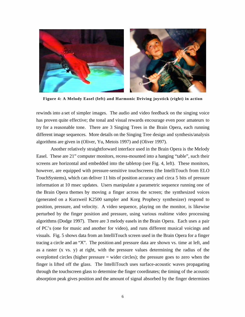
Figure 4: A Melody Easel (left) and Harmonic Driving joystick (right) in action
rewinds into a set of simpler images. The audio and video feedback on the singing voice
has proven quite effective; the tonal and visual rewards encourage even poor amateurs to
try for a reasonable tone. There are 3 Singing Trees in the Brain Opera, each running
different image sequences. More details on the Singing Tree design and synthesis/analysis
algorithms are given in (Oliver, Yu, Metois 1997) and (Oliver 1997).
Another relatively straightforward interface used in the Brain Opera is the Melody
Easel. These are 21” computer monitors, recess-mounted into a hanging “table”, such their
screens are horizontal and embedded into the tabletop (see Fig. 4, left). These monitors,
however, are equipped with pressure-sensitive touchscreens (the IntelliTouch from ELO
TouchSystems), which can deliver 11 bits of position accuracy and circa 5 bits of pressure
information at 10 msec updates. Users manipulate a parametric sequence running one of
the Brain Opera themes by moving a finger across the screen; the synthesized voices
(generated on a Kurzweil K2500 sampler and Korg Prophecy synthesizer) respond to
position, pressure, and velocity. A video sequence, playing on the monitor, is likewise
perturbed by the finger position and pressure, using various realtime video processing
algorithms (Dodge 1997). There are 3 melody easels in the Brain Opera. Each uses a pair
of PC’s (one for music and another for video), and runs different musical voicings and
visuals. Fig. 5 shows data from an IntelliTouch screen used in the Brain Opera for a finger
tracing a circle and an “X”. The position and pressure data are shown vs. time at left, and
as a raster (x vs. y) at right, with the pressure values determining the radius of the
overplotted circles (higher pressure = wider circles); the pressure goes to zero when the
finger is lifted off the glass. The IntelliTouch uses surface-acoustic waves propagating
through the touchscreen glass to determine the finger coordinates; the timing of the acoustic
absorption peak gives position and the amount of signal absorbed by the finger determines
6
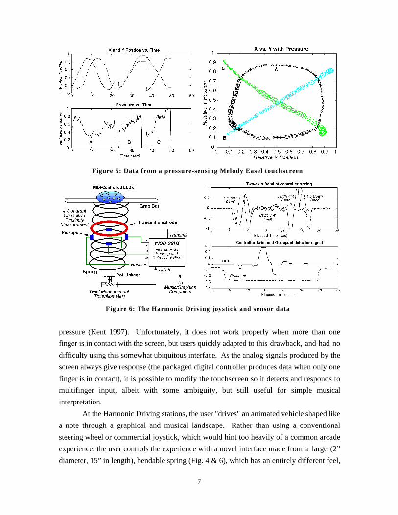
Figure 5: Data from a pressure-sensing Melody Easel touchscreen
Figure 6: The Harmonic Driving joystick and sensor data
pressure (Kent 1997). Unfortunately, it does not work properly when more than one
finger is in contact with the screen, but users quickly adapted to this drawback, and had no
difficulty using this somewhat ubiquitous interface. As the analog signals produced by the
screen always give response (the packaged digital controller produces data when only one
finger is in contact), it is possible to modify the touchscreen so it detects and responds to
multifinger input, albeit with some ambiguity, but still useful for simple musical
interpretation.
At the Harmonic Driving stations, the user "drives" an animated vehicle shaped like
a note through a graphical and musical landscape. Rather than using a conventional
steering wheel or commercial joystick, which would hint too heavily of a common arcade
experience, the user controls the experience with a novel interface made from a large (2”
diameter, 15” in length), bendable spring (Fig. 4 & 6), which has an entirely different feel,
7
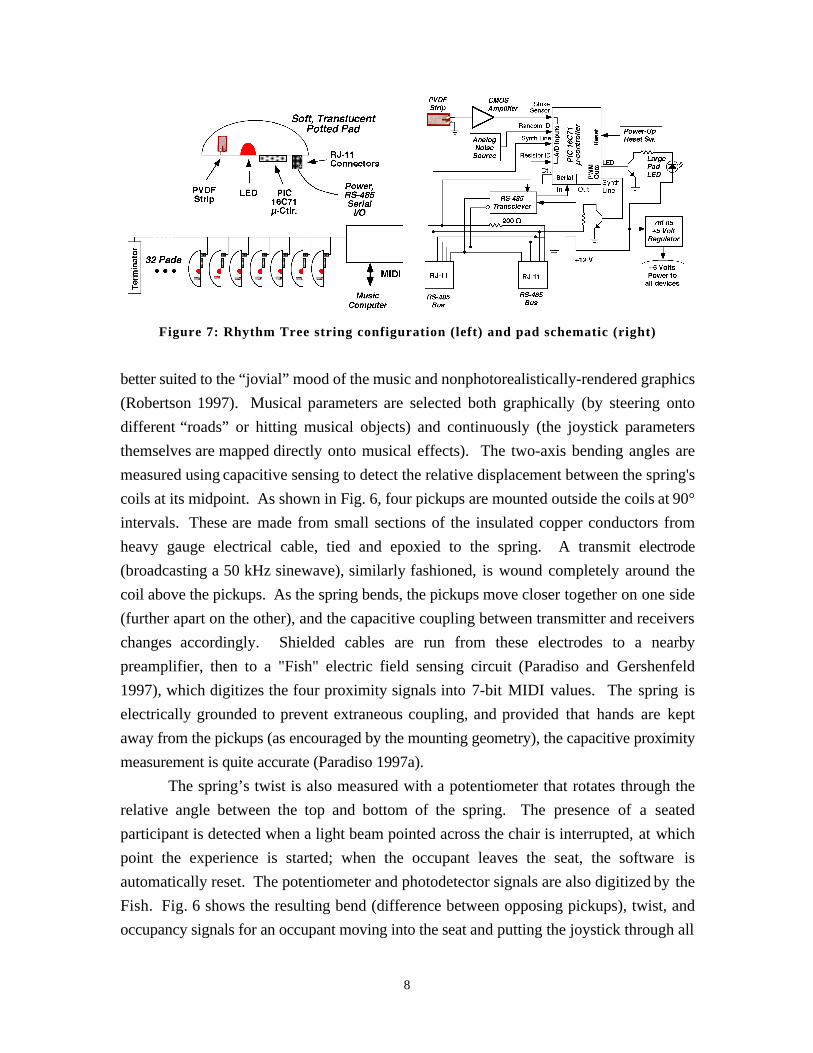
Figure 7: Rhythm Tree string configuration (left) and pad schematic (right)
better suited to the “jovial” mood of the music and nonphotorealistically-rendered graphics
(Robertson 1997). Musical parameters are selected both graphically (by steering onto
different “roads” or hitting musical objects) and continuously (the joystick parameters
themselves are mapped directly onto musical effects). The two-axis bending angles are
measured using capacitive sensing to detect the relative displacement between the spring's
coils at its midpoint. As shown in Fig. 6, four pickups are mounted outside the coils at 90°
intervals. These are made from small sections of the insulated copper conductors from
heavy gauge electrical cable, tied and epoxied to the spring. A transmit electrode
(broadcasting a 50 kHz sinewave), similarly fashioned, is wound completely around the
coil above the pickups. As the spring bends, the pickups move closer together on one side
(further apart on the other), and the capacitive coupling between transmitter and receivers
changes accordingly. Shielded cables are run from these electrodes to a nearby
preamplifier, then to a "Fish" electric field sensing circuit (Paradiso and Gershenfeld
1997), which digitizes the four proximity signals into 7-bit MIDI values. The spring is
electrically grounded to prevent extraneous coupling, and provided that hands are kept
away from the pickups (as encouraged by the mounting geometry), the capacitive proximity
measurement is quite accurate (Paradiso 1997a).
The spring’s twist is also measured with a potentiometer that rotates through the
relative angle between the top and bottom of the spring. The presence of a seated
participant is detected when a light beam pointed across the chair is interrupted, at which
point the experience is started; when the occupant leaves the seat, the software is
automatically reset. The potentiometer and photodetector signals are also digitized by the
Fish. Fig. 6 shows the resulting bend (difference between opposing pickups), twist, and
occupancy signals for an occupant moving into the seat and putting the joystick through all
8
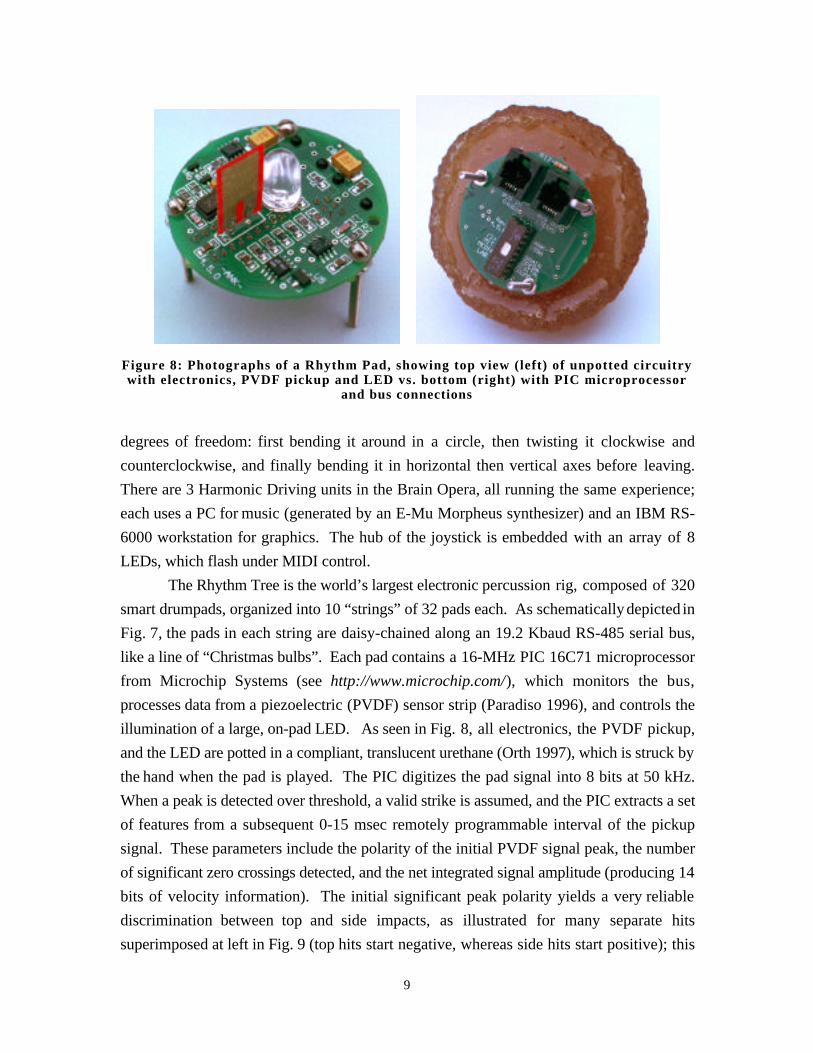
Figure 8: Photographs of a Rhythm Pad, showing top view (left) of unpotted circuitrywith electronics, PVDF pickup and LED vs. bottom (right) with PIC microprocessor
and bus connections
degrees of freedom: first bending it around in a circle, then twisting it clockwise and
counterclockwise, and finally bending it in horizontal then vertical axes before leaving.
There are 3 Harmonic Driving units in the Brain Opera, all running the same experience;
each uses a PC for music (generated by an E-Mu Morpheus synthesizer) and an IBM RS-
6000 workstation for graphics. The hub of the joystick is embedded with an array of 8
LEDs, which flash under MIDI control.
The Rhythm Tree is the world’s largest electronic percussion rig, composed of 320
smart drumpads, organized into 10 “strings” of 32 pads each. As schematically depicted in
Fig. 7, the pads in each string are daisy-chained along an 19.2 Kbaud RS-485 serial bus,
like a line of “Christmas bulbs”. Each pad contains a 16-MHz PIC 16C71 microprocessor
from Microchip Systems (see http://www.microchip.com/), which monitors the bus,
processes data from a piezoelectric (PVDF) sensor strip (Paradiso 1996), and controls the
illumination of a large, on-pad LED. As seen in Fig. 8, all electronics, the PVDF pickup,
and the LED are potted in a compliant, translucent urethane (Orth 1997), which is struck by
the hand when the pad is played. The PIC digitizes the pad signal into 8 bits at 50 kHz.
When a peak is detected over threshold, a valid strike is assumed, and the PIC extracts a set
of features from a subsequent 0-15 msec remotely programmable interval of the pickup
signal. These parameters include the polarity of the initial PVDF signal peak, the number
of significant zero crossings detected, and the net integrated signal amplitude (producing 14
bits of velocity information). The initial significant peak polarity yields a very reliable
discrimination between top and side impacts, as illustrated for many separate hits
superimposed at left in Fig. 9 (top hits start negative, whereas side hits start positive); this
9
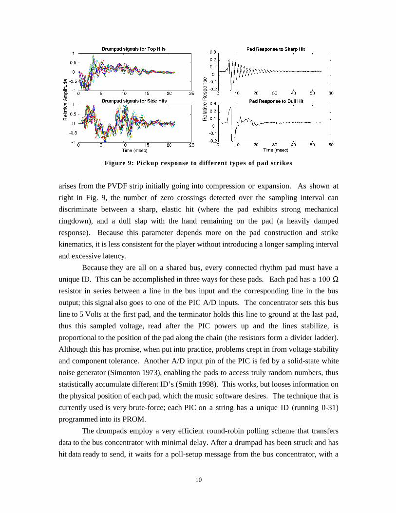
Figure 9: Pickup response to different types of pad strikes
arises from the PVDF strip initially going into compression or expansion. As shown at
right in Fig. 9, the number of zero crossings detected over the sampling interval can
discriminate between a sharp, elastic hit (where the pad exhibits strong mechanical
ringdown), and a dull slap with the hand remaining on the pad (a heavily damped
response). Because this parameter depends more on the pad construction and strike
kinematics, it is less consistent for the player without introducing a longer sampling interval
and excessive latency.
Because they are all on a shared bus, every connected rhythm pad must have a
unique ID. This can be accomplished in three ways for these pads. Each pad has a 100 Ωresistor in series between a line in the bus input and the corresponding line in the bus
output; this signal also goes to one of the PIC A/D inputs. The concentrator sets this bus
line to 5 Volts at the first pad, and the terminator holds this line to ground at the last pad,
thus this sampled voltage, read after the PIC powers up and the lines stabilize, is
proportional to the position of the pad along the chain (the resistors form a divider ladder).
Although this has promise, when put into practice, problems crept in from voltage stability
and component tolerance. Another A/D input pin of the PIC is fed by a solid-state white
noise generator (Simonton 1973), enabling the pads to access truly random numbers, thus
statistically accumulate different ID’s (Smith 1998). This works, but looses information on
the physical position of each pad, which the music software desires. The technique that is
currently used is very brute-force; each PIC on a string has a unique ID (running 0-31)
programmed into its PROM.
The drumpads employ a very efficient round-robin polling scheme that transfers
data to the bus concentrator with minimal delay. After a drumpad has been struck and has
hit data ready to send, it waits for a poll-setup message from the bus concentrator, with a
10
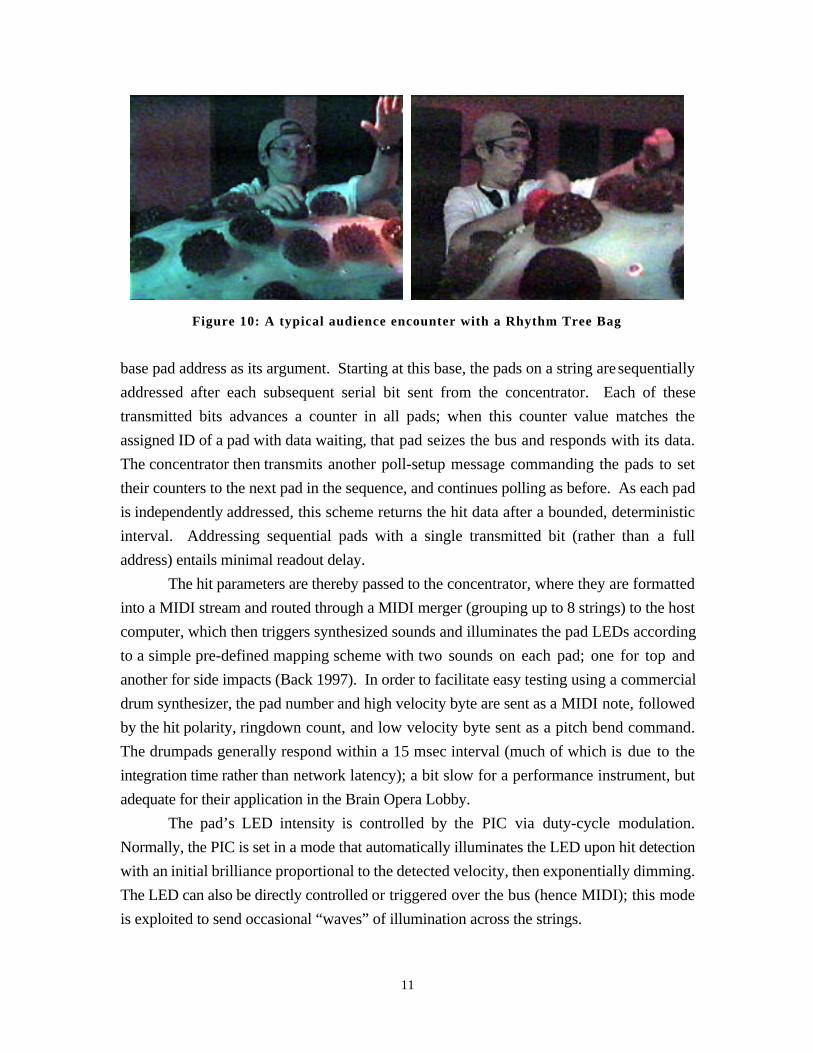
Figure 10: A typical audience encounter with a Rhythm Tree Bag
base pad address as its argument. Starting at this base, the pads on a string are sequentially
addressed after each subsequent serial bit sent from the concentrator. Each of these
transmitted bits advances a counter in all pads; when this counter value matches the
assigned ID of a pad with data waiting, that pad seizes the bus and responds with its data.
The concentrator then transmits another poll-setup message commanding the pads to set
their counters to the next pad in the sequence, and continues polling as before. As each pad
is independently addressed, this scheme returns the hit data after a bounded, deterministic
interval. Addressing sequential pads with a single transmitted bit (rather than a full
address) entails minimal readout delay.
The hit parameters are thereby passed to the concentrator, where they are formatted
into a MIDI stream and routed through a MIDI merger (grouping up to 8 strings) to the host
computer, which then triggers synthesized sounds and illuminates the pad LEDs according
to a simple pre-defined mapping scheme with two sounds on each pad; one for top and
another for side impacts (Back 1997). In order to facilitate easy testing using a commercial
drum synthesizer, the pad number and high velocity byte are sent as a MIDI note, followed
by the hit polarity, ringdown count, and low velocity byte sent as a pitch bend command.
The drumpads generally respond within a 15 msec interval (much of which is due to the
integration time rather than network latency); a bit slow for a performance instrument, but
adequate for their application in the Brain Opera Lobby.
The pad’s LED intensity is controlled by the PIC via duty-cycle modulation.
Normally, the PIC is set in a mode that automatically illuminates the LED upon hit detection
with an initial brilliance proportional to the detected velocity, then exponentially dimming.
The LED can also be directly controlled or triggered over the bus (hence MIDI); this mode
is exploited to send occasional “waves” of illumination across the strings.
11
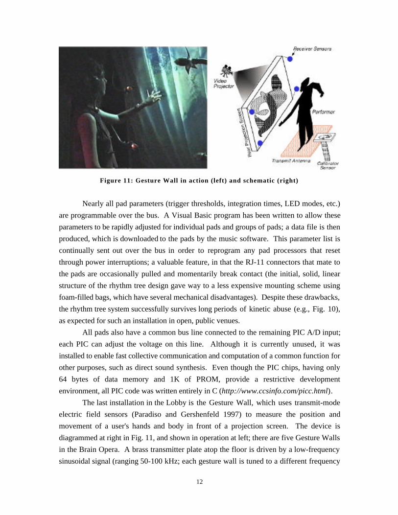
Figure 11: Gesture Wall in action (left) and schematic (right)
Nearly all pad parameters (trigger thresholds, integration times, LED modes, etc.)
are programmable over the bus. A Visual Basic program has been written to allow these
parameters to be rapidly adjusted for individual pads and groups of pads; a data file is then
produced, which is downloaded to the pads by the music software. This parameter list is
continually sent out over the bus in order to reprogram any pad processors that reset
through power interruptions; a valuable feature, in that the RJ-11 connectors that mate to
the pads are occasionally pulled and momentarily break contact (the initial, solid, linear
structure of the rhythm tree design gave way to a less expensive mounting scheme using
foam-filled bags, which have several mechanical disadvantages). Despite these drawbacks,
the rhythm tree system successfully survives long periods of kinetic abuse (e.g., Fig. 10),
as expected for such an installation in open, public venues.
All pads also have a common bus line connected to the remaining PIC A/D input;
each PIC can adjust the voltage on this line. Although it is currently unused, it was
installed to enable fast collective communication and computation of a common function for
other purposes, such as direct sound synthesis. Even though the PIC chips, having only
64 bytes of data memory and 1K of PROM, provide a restrictive development
environment, all PIC code was written entirely in C (http://www.ccsinfo.com/picc.html).
The last installation in the Lobby is the Gesture Wall, which uses transmit-mode
electric field sensors (Paradiso and Gershenfeld 1997) to measure the position and
movement of a user's hands and body in front of a projection screen. The device is
diagrammed at right in Fig. 11, and shown in operation at left; there are five Gesture Walls
in the Brain Opera. A brass transmitter plate atop the floor is driven by a low-frequency
sinusoidal signal (ranging 50-100 kHz; each gesture wall is tuned to a different frequency
12
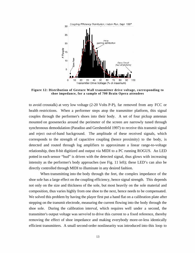
Figure 12: Distribution of Gesture Wall transmitter drive voltage, corresponding toshoe impedance, for a sample of 700 Brain Opera attendees
to avoid crosstalk) at very low voltage (2-20 Volts P-P), far removed from any FCC or
health restrictions. When a performer steps atop the transmitter platform, this signal
couples through the performer's shoes into their body. A set of four pickup antennas
mounted on goosenecks around the perimeter of the screen are narrowly tuned through
synchronous demodulation (Paradiso and Gershenfeld 1997) to receive this transmit signal
and reject out-of-band background. The amplitude of these received signals, which
corresponds to the strength of capacitive coupling (hence proximity) to the body, is
detected and routed through log amplifiers to approximate a linear range-to-voltage
relationship, then 8-bit digitized and output via MIDI to a PC running ROGUS. An LED
potted in each sensor “bud” is driven with the detected signal, thus glows with increasing
intensity as the performer's body approaches (see Fig. 11 left); these LED’s can also be
directly controlled through MIDI to illuminate in any desired fashion.
When transmitting into the body through the feet, the complex impedance of the
shoe sole has a large effect on the coupling efficiency, hence signal strength. This depends
not only on the size and thickness of the sole, but most heavily on the sole material and
composition, thus varies highly from one shoe to the next, hence needs to be compensated.
We solved this problem by having the player first put a hand flat on a calibration plate after
stepping on the transmit electrode, measuring the current flowing into the body through the
shoe sole. During the calibration interval, which requires well under a second, the
transmitter's output voltage was servo'ed to drive this current to a fixed reference, thereby
removing the effect of shoe impedance and making everybody more-or-less identically
efficient transmitters. A small second-order nonlinearity was introduced into this loop to
13
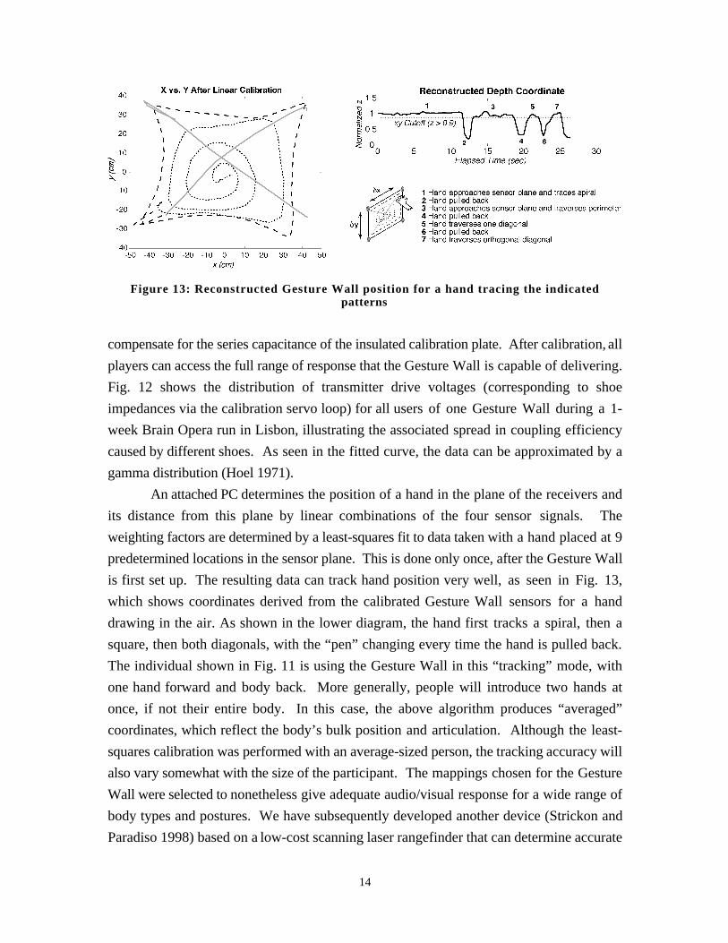
Figure 13: Reconstructed Gesture Wall position for a hand tracing the indicatedpatterns
compensate for the series capacitance of the insulated calibration plate. After calibration, all
players can access the full range of response that the Gesture Wall is capable of delivering.
Fig. 12 shows the distribution of transmitter drive voltages (corresponding to shoe
impedances via the calibration servo loop) for all users of one Gesture Wall during a 1-
week Brain Opera run in Lisbon, illustrating the associated spread in coupling efficiency
caused by different shoes. As seen in the fitted curve, the data can be approximated by a
gamma distribution (Hoel 1971).
An attached PC determines the position of a hand in the plane of the receivers and
its distance from this plane by linear combinations of the four sensor signals. The
weighting factors are determined by a least-squares fit to data taken with a hand placed at 9
predetermined locations in the sensor plane. This is done only once, after the Gesture Wall
is first set up. The resulting data can track hand position very well, as seen in Fig. 13,
which shows coordinates derived from the calibrated Gesture Wall sensors for a hand
drawing in the air. As shown in the lower diagram, the hand first tracks a spiral, then a
square, then both diagonals, with the “pen” changing every time the hand is pulled back.
The individual shown in Fig. 11 is using the Gesture Wall in this “tracking” mode, with
one hand forward and body back. More generally, people will introduce two hands at
once, if not their entire body. In this case, the above algorithm produces “averaged”
coordinates, which reflect the body’s bulk position and articulation. Although the least-
squares calibration was performed with an average-sized person, the tracking accuracy will
also vary somewhat with the size of the participant. The mappings chosen for the Gesture
Wall were selected to nonetheless give adequate audio/visual response for a wide range of
body types and postures. We have subsequently developed another device (Strickon and
Paradiso 1998) based on a low-cost scanning laser rangefinder that can determine accurate
14
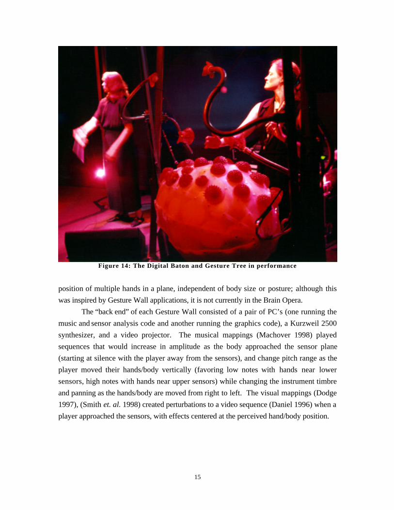
Figure 14: The Digital Baton and Gesture Tree in performance
position of multiple hands in a plane, independent of body size or posture; although this
was inspired by Gesture Wall applications, it is not currently in the Brain Opera.
The “back end” of each Gesture Wall consisted of a pair of PC’s (one running the
music and sensor analysis code and another running the graphics code), a Kurzweil 2500
synthesizer, and a video projector. The musical mappings (Machover 1998) played
sequences that would increase in amplitude as the body approached the sensor plane
(starting at silence with the player away from the sensors), and change pitch range as the
player moved their hands/body vertically (favoring low notes with hands near lower
sensors, high notes with hands near upper sensors) while changing the instrument timbre
and panning as the hands/body are moved from right to left. The visual mappings (Dodge
1997), (Smith et. al. 1998) created perturbations to a video sequence (Daniel 1996) when a
player approached the sensors, with effects centered at the perceived hand/body position.
15
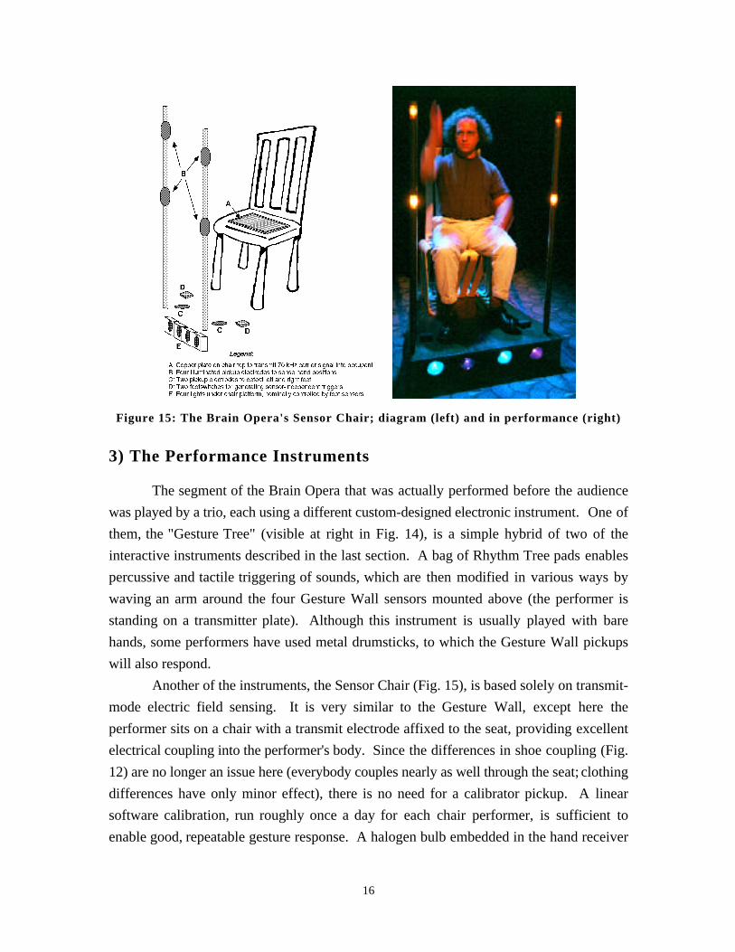
Figure 15: The Brain Opera's Sensor Chair; diagram (left) and in performance (right)
3) The Performance Instruments
The segment of the Brain Opera that was actually performed before the audience
was played by a trio, each using a different custom-designed electronic instrument. One of
them, the "Gesture Tree" (visible at right in Fig. 14), is a simple hybrid of two of the
interactive instruments described in the last section. A bag of Rhythm Tree pads enables
percussive and tactile triggering of sounds, which are then modified in various ways by
waving an arm around the four Gesture Wall sensors mounted above (the performer is
standing on a transmitter plate). Although this instrument is usually played with bare
hands, some performers have used metal drumsticks, to which the Gesture Wall pickups
will also respond.
Another of the instruments, the Sensor Chair (Fig. 15), is based solely on transmit-
mode electric field sensing. It is very similar to the Gesture Wall, except here the
performer sits on a chair with a transmit electrode affixed to the seat, providing excellent
electrical coupling into the performer's body. Since the differences in shoe coupling (Fig.
12) are no longer an issue here (everybody couples nearly as well through the seat; clothing
differences have only minor effect), there is no need for a calibrator pickup. A linear
software calibration, run roughly once a day for each chair performer, is sufficient to
enable good, repeatable gesture response. A halogen bulb embedded in the hand receiver
16
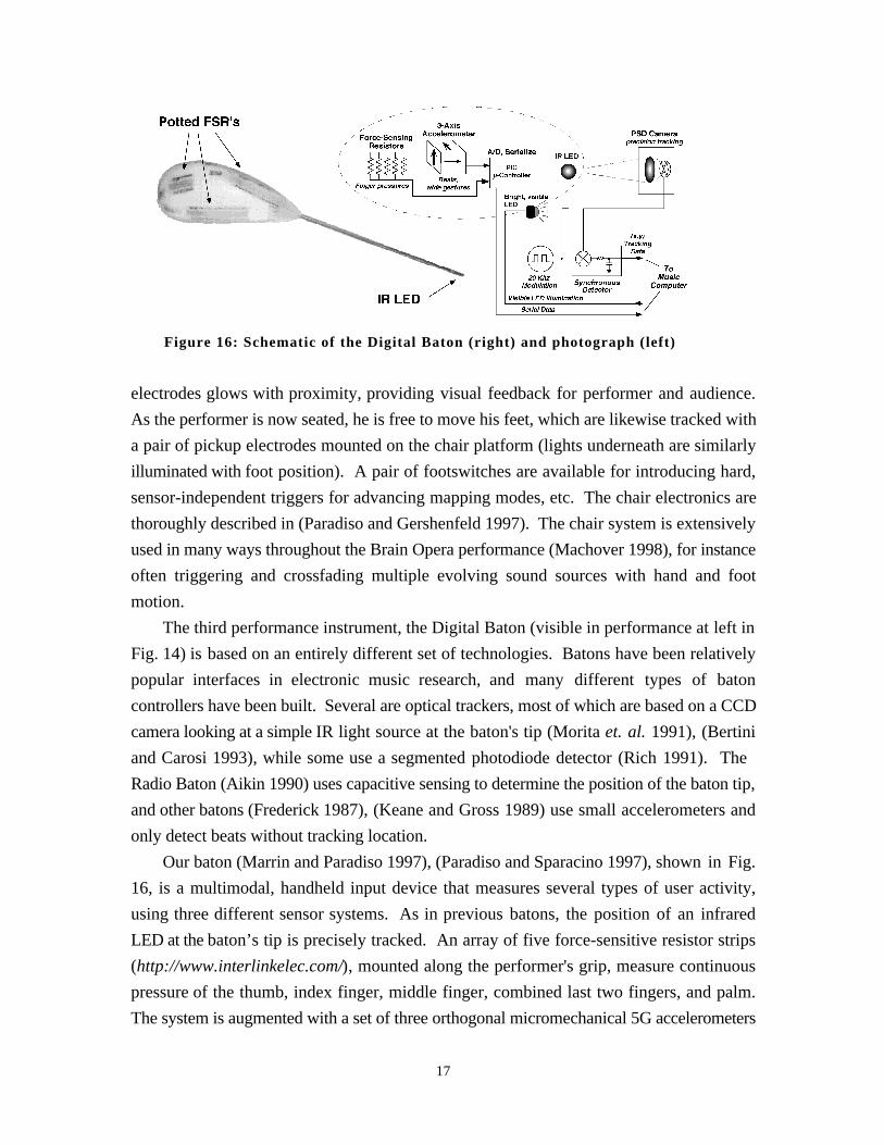
Figure 16: Schematic of the Digital Baton (right) and photograph (left)
electrodes glows with proximity, providing visual feedback for performer and audience.
As the performer is now seated, he is free to move his feet, which are likewise tracked with
a pair of pickup electrodes mounted on the chair platform (lights underneath are similarly
illuminated with foot position). A pair of footswitches are available for introducing hard,
sensor-independent triggers for advancing mapping modes, etc. The chair electronics are
thoroughly described in (Paradiso and Gershenfeld 1997). The chair system is extensively
used in many ways throughout the Brain Opera performance (Machover 1998), for instance
often triggering and crossfading multiple evolving sound sources with hand and foot
motion.
The third performance instrument, the Digital Baton (visible in performance at left in
Fig. 14) is based on an entirely different set of technologies. Batons have been relatively
popular interfaces in electronic music research, and many different types of baton
controllers have been built. Several are optical trackers, most of which are based on a CCD
camera looking at a simple IR light source at the baton's tip (Morita et. al. 1991), (Bertini
and Carosi 1993), while some use a segmented photodiode detector (Rich 1991). The
Radio Baton (Aikin 1990) uses capacitive sensing to determine the position of the baton tip,
and other batons (Frederick 1987), (Keane and Gross 1989) use small accelerometers and
only detect beats without tracking location.
Our baton (Marrin and Paradiso 1997), (Paradiso and Sparacino 1997), shown in Fig.
16, is a multimodal, handheld input device that measures several types of user activity,
using three different sensor systems. As in previous batons, the position of an infrared
LED at the baton’s tip is precisely tracked. An array of five force-sensitive resistor strips
(http://www.interlinkelec.com/), mounted along the performer's grip, measure continuous
pressure of the thumb, index finger, middle finger, combined last two fingers, and palm.
The system is augmented with a set of three orthogonal micromechanical 5G accelerometers
17
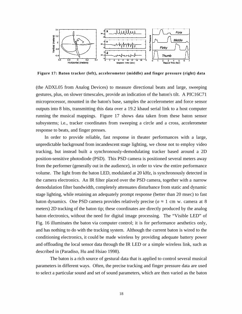
Figure 17: Baton tracker (left), accelerometer (middle) and finger pressure (right) data
(the ADXL05 from Analog Devices) to measure directional beats and large, sweeping
gestures, plus, on slower timescales, provide an indication of the baton's tilt. A PIC16C71
microprocessor, mounted in the baton's base, samples the accelerometer and force sensor
outputs into 8 bits, transmitting this data over a 19.2 kbaud serial link to a host computer
running the musical mappings. Figure 17 shows data taken from these baton sensor
subsystems; i.e., tracker coordinates from sweeping a circle and a cross, accelerometer
response to beats, and finger presses.
In order to provide reliable, fast response in theater performances with a large,
unpredictable background from incandescent stage lighting, we chose not to employ video
tracking, but instead built a synchronously-demodulating tracker based around a 2D
position-sensitive photodiode (PSD). This PSD camera is positioned several meters away
from the performer (generally out in the audience), in order to view the entire performance
volume. The light from the baton LED, modulated at 20 kHz, is synchronously detected in
the camera electronics. An IR filter placed over the PSD camera, together with a narrow
demodulation filter bandwidth, completely attenuates disturbance from static and dynamic
stage lighting, while retaining an adequately prompt response (better than 20 msec) to fast
baton dynamics. One PSD camera provides relatively precise (σ ≈ 1 cm w. camera at 8
meters) 2D tracking of the baton tip; these coordinates are directly produced by the analog
baton electronics, without the need for digital image processing. The “Visible LED” of
Fig. 16 illuminates the baton via computer control; it is for performance aesthetics only,
and has nothing to do with the tracking system. Although the current baton is wired to the
conditioning electronics, it could be made wireless by providing adequate battery power
and offloading the local sensor data through the IR LED or a simple wireless link, such as
described in (Paradiso, Hu and Hsiao 1998).
The baton is a rich source of gestural data that is applied to control several musical
parameters in different ways. Often, the precise tracking and finger pressure data are used
to select a particular sound and set of sound parameters, which are then varied as the baton
18
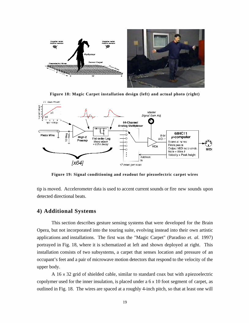
Figure 18: Magic Carpet installation design (left) and actual photo (right)
Figure 19: Signal conditioning and readout for piezoelectric carpet wires
tip is moved. Accelerometer data is used to accent current sounds or fire new sounds upon
detected directional beats.
4) Additional Systems
This section describes gesture sensing systems that were developed for the Brain
Opera, but not incorporated into the touring suite, evolving instead into their own artistic
applications and installations. The first was the "Magic Carpet" (Paradiso et. al. 1997)
portrayed in Fig. 18, where it is schematized at left and shown deployed at right. This
installation consists of two subsystems, a carpet that senses location and pressure of an
occupant’s feet and a pair of microwave motion detectors that respond to the velocity of the
upper body.
A 16 x 32 grid of shielded cable, similar to standard coax but with a piezoelectric
copolymer used for the inner insulation, is placed under a 6 x 10 foot segment of carpet, as
outlined in Fig. 18. The wires are spaced at a roughly 4-inch pitch, so that at least one will
19
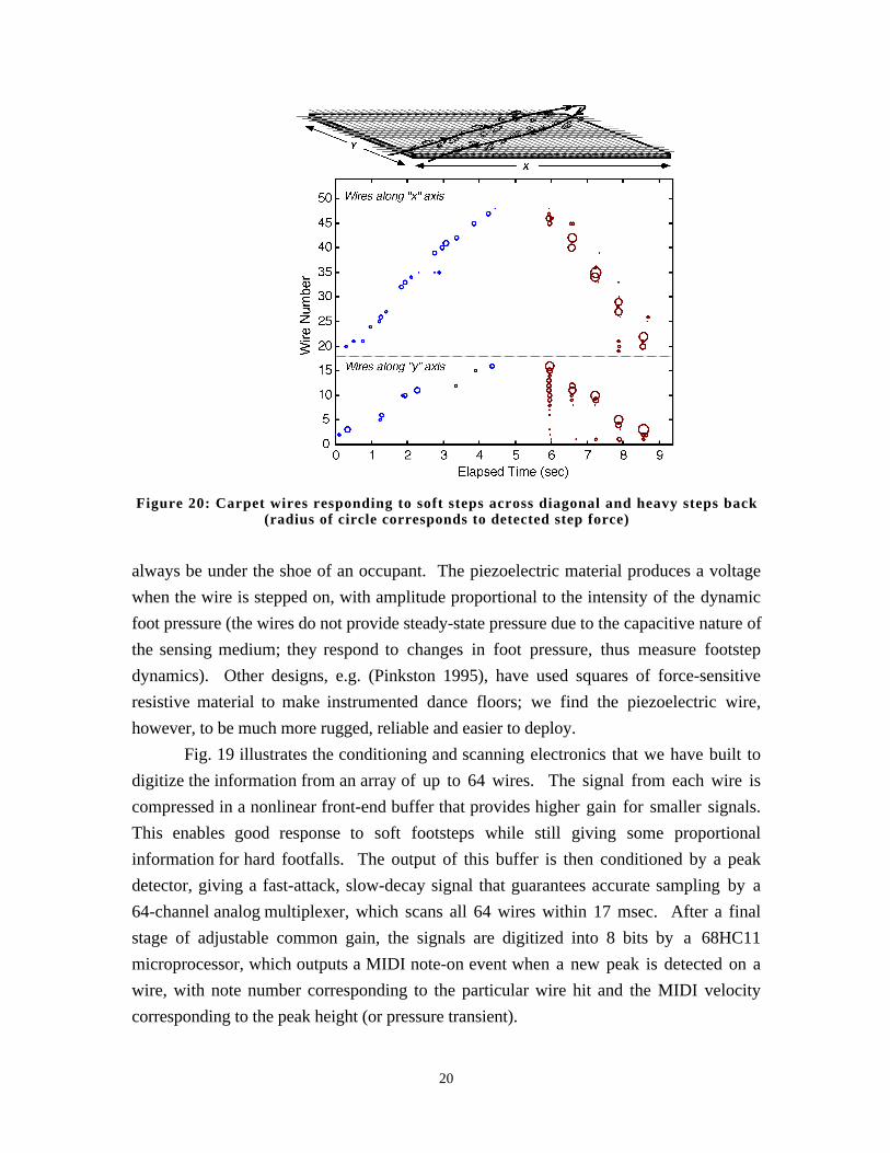
Figure 20: Carpet wires responding to soft steps across diagonal and heavy steps back(radius of circle corresponds to detected step force)
always be under the shoe of an occupant. The piezoelectric material produces a voltage
when the wire is stepped on, with amplitude proportional to the intensity of the dynamic
foot pressure (the wires do not provide steady-state pressure due to the capacitive nature of
the sensing medium; they respond to changes in foot pressure, thus measure footstep
dynamics). Other designs, e.g. (Pinkston 1995), have used squares of force-sensitive
resistive material to make instrumented dance floors; we find the piezoelectric wire,
however, to be much more rugged, reliable and easier to deploy.
Fig. 19 illustrates the conditioning and scanning electronics that we have built to
digitize the information from an array of up to 64 wires. The signal from each wire is
compressed in a nonlinear front-end buffer that provides higher gain for smaller signals.
This enables good response to soft footsteps while still giving some proportional
information for hard footfalls. The output of this buffer is then conditioned by a peak
detector, giving a fast-attack, slow-decay signal that guarantees accurate sampling by a
64-channel analog multiplexer, which scans all 64 wires within 17 msec. After a final
stage of adjustable common gain, the signals are digitized into 8 bits by a 68HC11
microprocessor, which outputs a MIDI note-on event when a new peak is detected on a
wire, with note number corresponding to the particular wire hit and the MIDI velocity
corresponding to the peak height (or pressure transient).
20
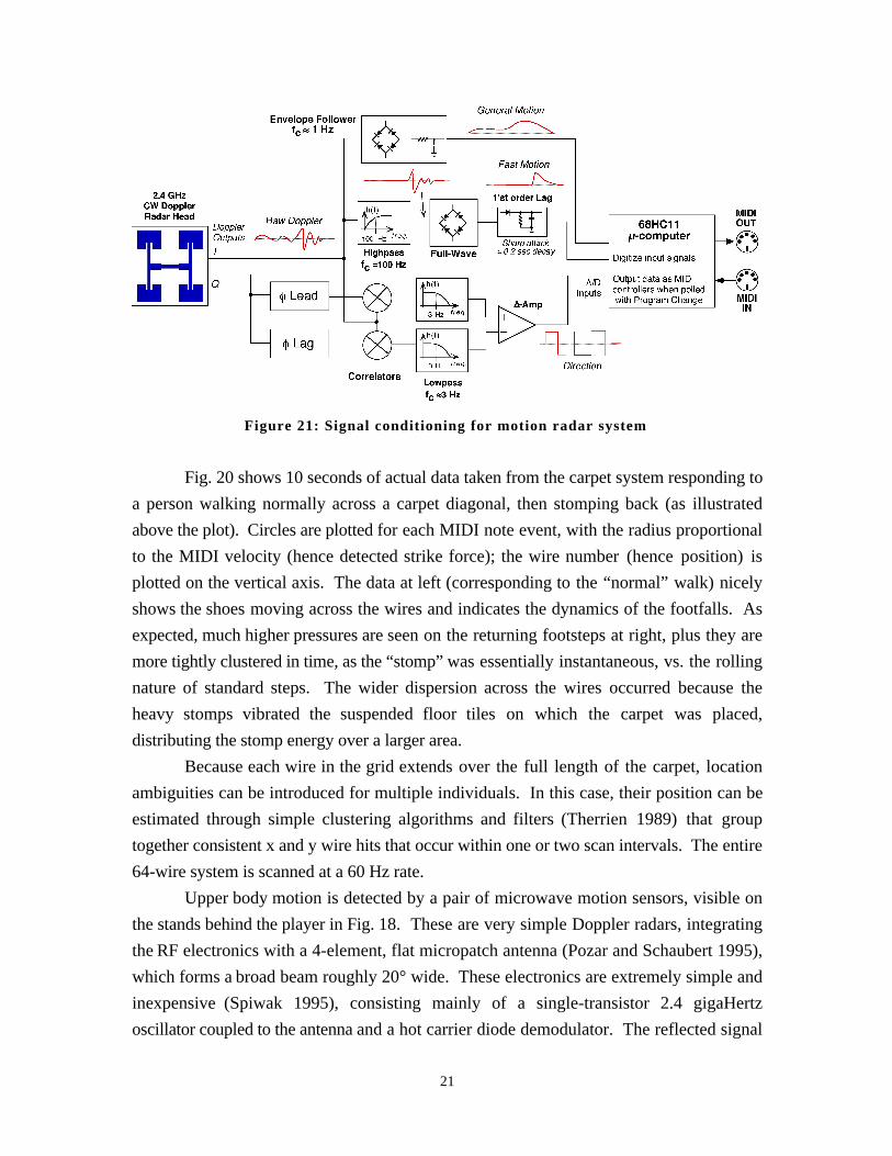
Figure 21: Signal conditioning for motion radar system
Fig. 20 shows 10 seconds of actual data taken from the carpet system responding to
a person walking normally across a carpet diagonal, then stomping back (as illustrated
above the plot). Circles are plotted for each MIDI note event, with the radius proportional
to the MIDI velocity (hence detected strike force); the wire number (hence position) is
plotted on the vertical axis. The data at left (corresponding to the “normal” walk) nicely
shows the shoes moving across the wires and indicates the dynamics of the footfalls. As
expected, much higher pressures are seen on the returning footsteps at right, plus they are
more tightly clustered in time, as the “stomp” was essentially instantaneous, vs. the rolling
nature of standard steps. The wider dispersion across the wires occurred because the
heavy stomps vibrated the suspended floor tiles on which the carpet was placed,
distributing the stomp energy over a larger area.
Because each wire in the grid extends over the full length of the carpet, location
ambiguities can be introduced for multiple individuals. In this case, their position can be
estimated through simple clustering algorithms and filters (Therrien 1989) that group
together consistent x and y wire hits that occur within one or two scan intervals. The entire
64-wire system is scanned at a 60 Hz rate.
Upper body motion is detected by a pair of microwave motion sensors, visible on
the stands behind the player in Fig. 18. These are very simple Doppler radars, integrating
the RF electronics with a 4-element, flat micropatch antenna (Pozar and Schaubert 1995),
which forms a broad beam roughly 20° wide. These electronics are extremely simple and
inexpensive (Spiwak 1995), consisting mainly of a single-transistor 2.4 gigaHertz
oscillator coupled to the antenna and a hot carrier diode demodulator. The reflected signal
21
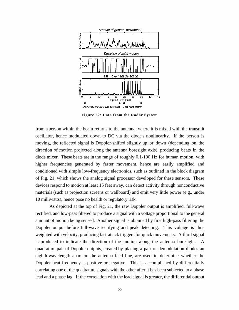
Figure 22: Data from the Radar System
from a person within the beam returns to the antenna, where it is mixed with the transmit
oscillator, hence modulated down to DC via the diode's nonlinearity. If the person is
moving, the reflected signal is Doppler-shifted slightly up or down (depending on the
direction of motion projected along the antenna boresight axis), producing beats in the
diode mixer. These beats are in the range of roughly 0.1-100 Hz for human motion, with
higher frequencies generated by faster movement, hence are easily amplified and
conditioned with simple low-frequency electronics, such as outlined in the block diagram
of Fig. 21, which shows the analog signal processor developed for these sensors. These
devices respond to motion at least 15 feet away, can detect activity through nonconductive
materials (such as projection screens or wallboard) and emit very little power (e.g., under
10 milliwatts), hence pose no health or regulatory risk.
As depicted at the top of Fig. 21, the raw Doppler output is amplified, full-wave
rectified, and low-pass filtered to produce a signal with a voltage proportional to the general
amount of motion being sensed. Another signal is obtained by first high-pass filtering the
Doppler output before full-wave rectifying and peak detecting. This voltage is thus
weighted with velocity, producing fast-attack triggers for quick movements. A third signal
is produced to indicate the direction of the motion along the antenna boresight. A
quadrature pair of Doppler outputs, created by placing a pair of demodulation diodes an
eighth-wavelength apart on the antenna feed line, are used to determine whether the
Doppler beat frequency is positive or negative. This is accomplished by differentially
correlating one of the quadrature signals with the other after it has been subjected to a phase
lead and a phase lag. If the correlation with the lead signal is greater, the differential output
22
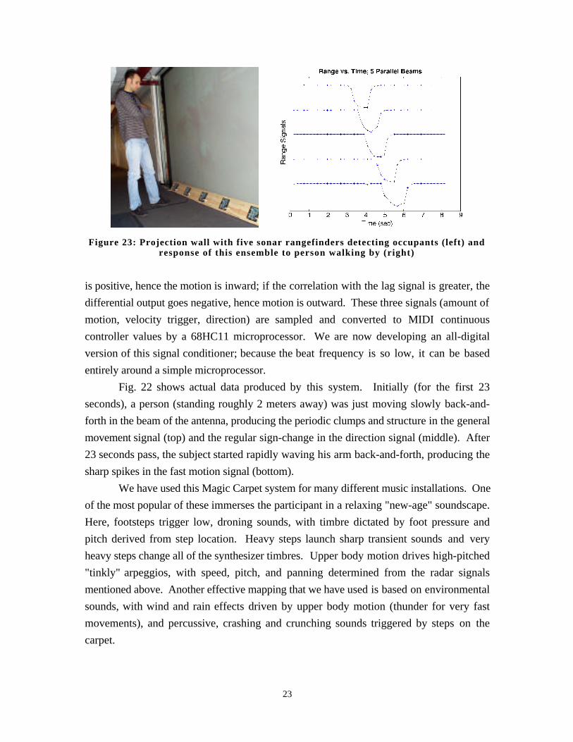
Figure 23: Projection wall with five sonar rangefinders detecting occupants (left) andresponse of this ensemble to person walking by (right)
is positive, hence the motion is inward; if the correlation with the lag signal is greater, the
differential output goes negative, hence motion is outward. These three signals (amount of
motion, velocity trigger, direction) are sampled and converted to MIDI continuous
controller values by a 68HC11 microprocessor. We are now developing an all-digital
version of this signal conditioner; because the beat frequency is so low, it can be based
entirely around a simple microprocessor.
Fig. 22 shows actual data produced by this system. Initially (for the first 23
seconds), a person (standing roughly 2 meters away) was just moving slowly back-and-
forth in the beam of the antenna, producing the periodic clumps and structure in the general
movement signal (top) and the regular sign-change in the direction signal (middle). After
23 seconds pass, the subject started rapidly waving his arm back-and-forth, producing the
sharp spikes in the fast motion signal (bottom).
We have used this Magic Carpet system for many different music installations. One
of the most popular of these immerses the participant in a relaxing "new-age" soundscape.
Here, footsteps trigger low, droning sounds, with timbre dictated by foot pressure and
pitch derived from step location. Heavy steps launch sharp transient sounds and very
heavy steps change all of the synthesizer timbres. Upper body motion drives high-pitched
"tinkly" arpeggios, with speed, pitch, and panning determined from the radar signals
mentioned above. Another effective mapping that we have used is based on environmental
sounds, with wind and rain effects driven by upper body motion (thunder for very fast
movements), and percussive, crashing and crunching sounds triggered by steps on the
carpet.
23
Another sensor system was developed for application in the Brain Opera, where it
was originally desired to measure the general presence and position of occupants at
different locations in the Lobby. This evolved into a multi-channel sonar rangefinder,
where up to eight independent sonar heads (visible at bottom in Fig. 23 left) can be attached
to a central MIDI controller with simple telephone cable and easily placed wherever a range
measurement is needed. The sonar heads themselves use 40 kHz piezoceramic transducers
with an onboard time-variable gain (TVG) amplifier, enabling detection of people and
objects from 1 to 25 feet away. The sonar heads are quite self-contained; each takes a
trigger input to produce a brief 40 kHz burst, then provides a discriminated return pulse
from the first detected echo, an analog voltage proportional to the first reflection's range,
and a detected echo envelope. The sonar controller pings the sonar heads individually or
collectively under MIDI command, then digitizes the resulting range-varying voltage into 7
bits to produce MIDI controller values as output. Although the well-known Polaroid
electrostatic sonar system (Ciarcia 1984) can sense out to longer range (e.g., 35 feet) and
has been used as a musical interface before (e.g., Gehlhaar 1991), the piezoceramic
transducers used here are very much quieter (the standard electrostatic transducers produce
loud audible clicks when pinged), plus exhibit a much wider beamwidth (40° for the
devices used here), which is more useful for most gesture-sensing applications.
Fig. 23 shows a group of these sonar heads deployed below a projection screen,
where they detect and measure the range to observers, causing projected video sequences to
evolve accordingly (Davenport et. al. 1997).
5) Discussion and Future Work
This paper has presented many new and unconventional interfaces for interacting
with musical environments. The forms taken by most of these interfaces also differed
vastly from the familiar trappings of human-computer interfaces (e.g., keyboards, mice,
etc.) and musical interfaces (Paradiso 1997b), edging toward responsive environments
built out of smart objects and sensitive spaces, where any kind of physical activity or
motion can result in a sophisticated multimedia reaction. Brain Opera audiences tended to
be very accepting of this premise; after first seeing the Lobby, many were seduced into
expecting musical response from all objects in the vicinity, including sculptures, etc. that
were originally in the space and not part of our installation.
The musical mappings running on the interactive instruments are fairly intuitive and
encourage exploration. When the Brain Opera first opened, we gave little or no orientation
to the audience, allowing them raw access to the Lobby installations. After a few days, we
24
decided to give the audiences a brief lecture or handout outlining the basic experiences and
modes of operation before they started, reducing confusion and significantly improving the
quality of their Lobby visit. The design of interactive music environments that avoid this
step by perceiving and dynamically adapting to the skill level or style of the participants is
an interesting direction for future research.
The Brain Opera's musical mappings and parametric sequences ran independently
on each Lobby instrument. Although this satisfied individual players (many of whom were
acoustically isolated by wearing headphones or were near appropriate speakers), the overall
sound of the Brain Opera Lobby quickly dropped to the familiar, stochastic level of an
arcade. Indeed, chaos in the Lobby was declared as an integral artistic goal of the Brain
Opera from the beginning (Machover 1996), and it is doubtful that any significant level of
collective musical expression was achieved. In general, future research is needed to
address the balance between overall and local experiences, e.g., selecting and coordinating
the audio responses over a network to enable large installations like the Brain Opera to
sound more musically coherent to an outside observer while still retaining enough
deterministic action-to-response musical feedback to satisfy individual participants.
Although our early concepts in blending the Brain Opera performance and Lobby
segments were ambitious and exciting, because of the extreme deadline pressure in a
project of this scale, the inclusion of audience activity and control inputs into the actual
performances were limited to the recordings left on the Speaking Trees and a brief Internet
interlude (Braham 1997).
There is considerable discussion (e.g., Rothenberg 1996) on the role of electronic
instruments for musical performance that abstract conventional audience expectations or
causal effect by including a sophisticated computer mapping in their response and/or are
based on the sensing of abstract gesture. Judging from our experiences with the Brain
Opera performances, most of which were given to the general public and not an audience
literate in computer music, it is mandatory that composers, performers, and instrument
designers work to bridge this disconnection in order to keep the audiences engaged and the
intensity and relevance of the performances high.
Although several of the Brain Opera's goals, as summarized in the introduction,
were achieved, it mainly represents an ambitious waypoint, hinting at the possibilities now
opening for large-scale participatory music installations. Through their experience, large
audiences were introduced to interactive music, and as touched on in the above discussion,
several questions have been raised and considerable public debate launched (e.g., Ross
1996), especially from the way in which this project refuses to fit into any clearly defined
25
musical category; something that will become increasingly frequent as the underlying
technology advances and such installations become more commonplace.
6) Acknowledgments
Although many people contributed to the Brain Opera at both creative and technical
levels, this paper concentrates on the achievements of the technology team. In particular,
acknowledgments are due to Ara Knaian for the Rhythm Tree system, Craig Abler for the
sensor carpet, Matt Reynolds for the motion radar, Ed Hammond for the Sensor Chair,
Theresa Marrin and Chris Verplaetse for the Baton, Will Oliver and John Yu for the
Singing Tree, Matt Gorbet and Rolf Rando for Harmonic Driving, Josh Smith for the
embedded code in most of these devices, Kai-Yuh Hsiao for musical mapping software,
and Rick Ciliberto and Joel Rosenberg for electronics fabrication. Maggie Orth’s role as
production director and object designer was key throughout the Brain Opera, as was the
work of the software team, namely Pete Rice, Ben Denckla and Patrick Pelletier.
Architectural elements were designed by Ray Kinoshita and the audio infrastructure
assembled by Maribeth Back and Ed Hammond. The animations and visuals were
produced by Sharon Daniel and graphics algorithms written by Chris Dodge. Last but
hardly least, Tod Machover is thanked for directing and pulling the Brain Opera together in
addition to writing the actual music. The help of the Physics and Media group was
appreciated, as is the support of our Media Lab and Brain Opera sponsors (see
http://brainop.media.mit.edu/sponsors.html). Additional images, diagrams, specifications,
and video clips of the installations described in this article can be found at
http://www.media.mit.edu/~joep/TTT.BO/index.html.
7) References
Back, M.J. (1997). Sound Design for Brain Opera's Mind Forest: Audio for a ComplexInteractive System. In Proceedings of the DIS97 Conference (pp. 23-25). New York:ACM Press.
Bertini, G., Carosi, P. (1993). Light Baton System: A System for Conducting ComputerMusic Performance. Interface, 22(3), 243-257.
Braham, R. (1997). The Web Resounding. IEEE Spectrum, 34(12), 27.
Chung, J. (1988). Hyperlisp Reference Manual. Technical report, Information andEntertainment Group, MIT Media Laboratory.
Ciarcia, S. (1984). An Ultrasonic Ranging System. BYTE, 9(11), 112-123.
Daniel, S., (1996). The Brain Opera Visual Design. See:http://brainop.media.mit.edu/Archive/visualdesign.html
26
Davenport, G., Agamanolis, S., Bradley, B., Paradiso, J., Spitzer, S. (1997). At the Edgeof DreamLand: Media Encounters in Architectural Venues. In Proceedings of the ISEA ‘97Conference.
Denckla, B. and Pelletier, P. (1996). The technical documentation for "Rogus McBogus",a MIDI library. Available at: http://theremin.media.mit.edu/rogus/ .
Dodge, C. (1997). The Abstraction, Transmission, and Reconstruction of Presence: AProposed Model for Computer Based Interactive Art. MS Thesis, Massachusetts Instituteof Technology, Media Lab.
Frederick, D. (1987). Airdrums, Rhythm Stick, Music Mouse; Make Mine MIDI, but Holdthe Keys. Keyboard, 13(1), 131-135,144.
Gehlhaar, R. (1991). SOUND=SPACE: an Interactive Musical Environment.Contemporary Music Review. 6(1): 59-72.
Kent, J. (1997). Acoustic touch position sensor using higher order horizontally polarizedshear wave propagation. US Patent No. 5591945.
Hoel, P.G. (1971). Introduction to Mathematical Statistics. New York: John Wiley &Sons.
Keane, D., Gross P. (1989). The MIDI Baton. In Proc. of the 1989 InternationalComputer Music Conference (pp. 151-154). San Francisco: International Computer MusicAssociation.
Machover, T. (1991). Hyperinstruments: A Composer’s Approach to the Evolution ofIntelligent Musical Instruments. In Cyberarts (pp. 67-76). San Francisco: WilliamFreeman.
Machover, T. (1996). The Brain Opera and Active Music. In G. Stocker, C. Schoepf(eds.), Memesis: The Future of Evolution, Proc. of the Ars Electronica 96 Festival (pp.300-309). Vienna: Springer.
Machover, T. (1998). BRAIN OPERA. Compact disk recording of music, with CD+additional text, photo and video information about the project and hyperinstruments. To bereleased in Fall 1998. Paris: Erato Disques/Warner.
Marrin, T., Paradiso, J. (1997). The Digital Baton: a Versatile Performance Instrument. InProc. of the 1997 International Computer Music Conference (pp. 313-316). San Francisco:International Computer Music Association.
Mathews, M. V. (1990). Three Dimensional Baton and Gesture Sensor. US Patent No.4,980,519, United States Patent Office.
Minsky, M. (1988). Society of Mind. New York: Simon and Schuster.
Morita, H., et. al. (1991). A Computer Music System that Follows a Human Conductor.IEEE Computer, 24(7), 44-53.
Oliver, W. (1997). The Singing Tree: A Novel Interactive Musical Experience. MS Thesis,Massachusetts Institute of Technology, Department of Electrical Engineering.
27
Oliver, W., Yu, J., Metois, E. (1997). The Singing Tree: Design of an Interactive MusicalInterface. In Proceedings of the DIS97 Conference (pp. 261-264). New York: ACMPress.
Orth, M. (1997). Interface to Architecture: Integrating Technology into the Environment inthe Brain Opera. In Proceedings of the DIS97 Conference (pp. 265-275). New York:ACM Press.
Paradiso, J. (1996). The Interactive Balloon: Sensing, Actuation and Behavior in aCommon Object. IBM Systems Journal, 35(3&4),473-487.
Paradiso, J. (1997a). New Technologies for Monitoring the Precision Alignment of LargeDetector Systems. Nuclear Instruments and Methods in Physics Research A386, 409-420.
Paradiso, J. (1997b). Electronic music interfaces: new ways to play. IEEE SpectrumMagazine, 34(12), 18-30.
Paradiso, J., Gershenfeld, N. (1997). Musical Applications of Electric Field Sensing.Computer Music Journal, 21(3), 69-89.
Paradiso, J., Sparacino, F. (1997). Optical tracking for music and dance performance. InA. Gruen, H. Kahmen (eds.), Optical 3-D Measurement Techniques IV (pp. 11-18).Heidelberg: Herbert Wichmann Verlag.
Paradiso, J. et. al. (1997). The Magic Carpet: Physical Sensing for ImmersiveEnvironments. In Proc. of the CHI ‘97 Conf. on Human Factors in Computing Systems,Extended Abstracts, (pp. 277-278). New York: ACM Press.
Paradiso, J., Hu, E., and Hsiao, K. (1998). Instrumented Footwear for Interactive Dance.In Proc. of the XII Colloquium on Musical Informatics (pp. 89-92). Padova: Associazionedi Informatica Musicale Italiana.
Pinkston, R., et. al. (1995). A Touch Sensitive Dance Floor MIDI Controller. In Proc. ofthe 1995 International Computer Music Conference (pp. 224-225). San Francisco:International Computer Music Association.
Pozar, D.M., Schaubert, D.H., ed. (1995). Microstrip Antennas: The Analysis and Designof Microstrip Antennas and Arrays. New York: IEEE Press.
Rich, R. (1991). Buchla Lightning MIDI Controller. Electronic Musician, 7(10), 102-108.
Robertson, B. (1997). Different Strokes. Computer Graphics World, 20(12), 26-34.
Ross, A. (1996). Composers Wanted, No Experience Needed. The New York Times, July25, 1996, p. 13.
Rothenberg, D. (1996). Sudden Music: Improvising across the Electronic Abyss.Contemporary Music Review, 13(2), 23-46.
Rothstein, E. (1996). Connections: Describing Intelligence Through a Virtual Symphony.The New York Times, Technology Section, May 27, 1996, p. 31.
Simonton, J.S. (1973). More Synthesizer Modules. Radio-Electronics, 44, 53-60.
Smith, J.R. (1998). Distributed Protocols for ID Assignment. To appear in the IEEERobotics and Automation Magazine.
28
Smith, J.R., et. al. (1998). Electric Field Sensing for Graphical Interfaces. IEEE ComputerGraphics and Applications, 18(3), 54-60.
Spiwak, M. (1995). Build a Radar Speed Gun. Popular Electronics., 12(6), 37-42,90.
Strickon, J., Paradiso, J. (1998). Tracking Hands Above Large Interactive Surfaces with aLow-Cost Scanning Laser Rangefinder. CHI ‘98 Conf. on Human Factors in ComputingSystems, Summary (pp. 231-232). New York: ACM Press.
Therrien, C.W. (1989). Decision Estimation and Classification. New York: John Wiley &Sons.
Ulyate, R. (1998). Interactive Dance Club. SIGGRAPH98 Conference Abstracts andApplications (pp. 230-235). New York: ACM Press.
Wilkinson, S.W. (1997). Phantom of the Brain Opera. Electronic Musician, 13(1), 26-39.
Wren, C.R., et. al. (1997). Perceptive Spaces for Performance and Entertainment:Untethered Interaction using Computer Vision and Audition. Applied Artificial Intelligence,11(4), 267-284.
29
Joseph Paradiso (http://www.media.mit.edu/~joep/) is a principal research scientist at the
MIT Media Laboratory, where he leads a group that develops new sensing technologies for
responsive environments. He also directed the Brain Opera’s interface engineering team
and is currently the Technology Director for the Media Lab’s Things that Think
consortium. He received a B.S. in Electrical Engineering and Physics from Tufts
University in 1977 and a Ph.D. in Physics at the Massachusetts Institute of Technology in
1981, after which he developed high-energy physics detectors, spacecraft control
algorithms, and sensor systems at the Laboratory for High-Energy Physics at ETH in
Zurich and the Draper Laboratory in Cambridge, MA. He designs large music synthesizer
systems in his spare time, and is a member of the IEEE, AIAA, APS, and Sigma Xi.
30