the brakes - rroc · pdf fileremove the split cotter of the castellated nut j1 and unscrew the...
TRANSCRIPT

CHAPTER IV
The Brakes General-AdjustmentofRearandFrontBrakes(Chassispreviousto GAF-1) - Adjustment of Foot and Hand Brakes (Chassis GAF-1 andonwards)-AdjustmentofServo
THE BRAKES 53
General. The only points in the sytem where any adjustment is provided or is necessary are the following: - (i) Rear Brakes (ChassisprevioustoGAF-1). The threaded rods coupled to the cam operating levers below the ends of the rear axle Rear Brakes (ChassisGAF-1onwards). A wing nut Wr, for adjustment of the foot brakes, and the threaded rods coupled to the cam operating levers, Fig. 29, for adjustment of the handbrake. (ii) Front Brakes (ChassisprevioustoGAF-1). A serrated adjustment on the cam operating shafts. Front Brakes (ChassisGAF-1onwards). A wing nut adjustment, see Fig. 28. (iii) Servo. A serrated adjusting nut on the end of the servo shaft.
It is very important to observe that under no circumstances should adjusment be attempted at any other points, for instance, by altering the lengths of some of the brake rods or of any of the ropes. Any alterations to the lengths of these rods or ropes will virtually shorten the lengths of some of the levers, and will interfere with the correct functioning of the system.Adjustment of Rear Brakes. (ChassisprevioustoGAF-1). The state of adjustment of the rear brakes - both foot and hand-operated - should be tested by reference to movement of the brake cables necessary to take up the clearance between shoes and drums, or to the movement at the ends of the levers on the axle to which the cables are connected. For this purpose the cable should be pulled
or the lever operated by hand and the movement measured. This movement should never be less than 1” for both foot and hand brakes, but there is no need to adjust the brakes unless it exceeds 1½” for the foot brake, or 1¾” for the hand brake.
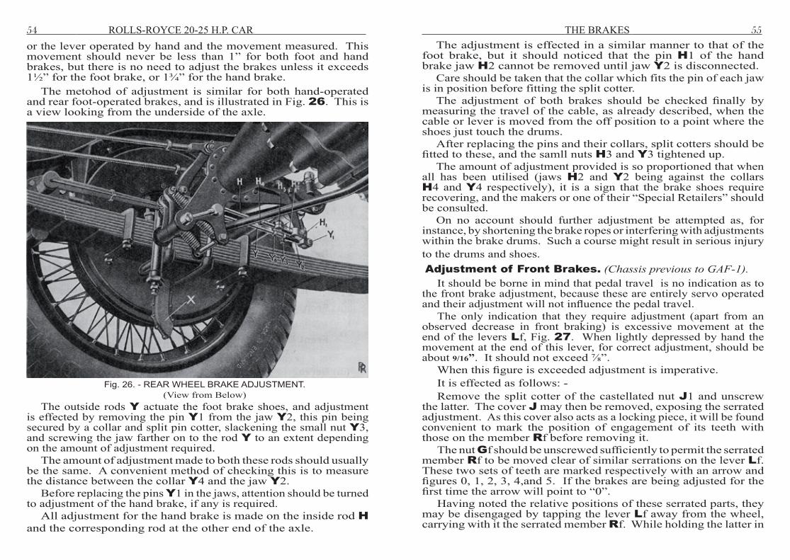
The metohod of adjustment is similar for both hand-operated and rear foot-operated brakes, and is illustrated in Fig. 26. This is a view looking from the underside of the axle.
Fig. 26. - REAR WHEEL BRAKE ADJUSTMENT.(View from Below)
The outside rods Y actuate the foot brake shoes, and adjustment is effected by removing the pin Y1 from the jaw Y2, this pin being secured by a collar and split pin cotter, slackening the small nut Y3, and screwing the jaw farther on to the rod Y to an extent depending on the amount of adjustment required.
The amount of adjustment made to both these rods should usually be the same. A convenient method of checking this is to measure the distance between the collar Y4 and the jaw Y2.
Before replacing the pins Y1 in the jaws, attention should be turned to adjustment of the hand brake, if any is required.
All adjustment for the hand brake is made on the inside rod H and the corresponding rod at the other end of the axle.
54 ROLLS-ROYCE 20-25 H.P. CAR
The adjustment is effected in a similar manner to that of the foot brake, but it should noticed that the pin H1 of the hand brake jaw H2 cannot be removed until jaw Y2 is disconnected.
Care should be taken that the collar which fits the pin of each jaw is in position before fitting the split cotter.
The adjustment of both brakes should be checked finally by measuring the travel of the cable, as already described, when the cable or lever is moved from the off position to a point where the shoes just touch the drums.
After replacing the pins and their collars, split cotters should be fitted to these, and the samll nuts H3 and Y3 tightened up.
The amount of adjustment provided is so proportioned that when all has been utilised (jaws H2 and Y2 being against the collars H4 and Y4 respectively), it is a sign that the brake shoes require recovering, and the makers or one of their “Special Retailers” should be consulted.
On no account should further adjustment be attempted as, for instance, by shortening the brake ropes or interfering with adjustments within the brake drums. Such a course might result in serious injury to the drums and shoes. Adjustment of Front Brakes. (ChassisprevioustoGAF-1).
It should be borne in mind that pedal travel is no indication as to the front brake adjustment, because these are entirely servo operated and their adjustment will not influence the pedal travel.
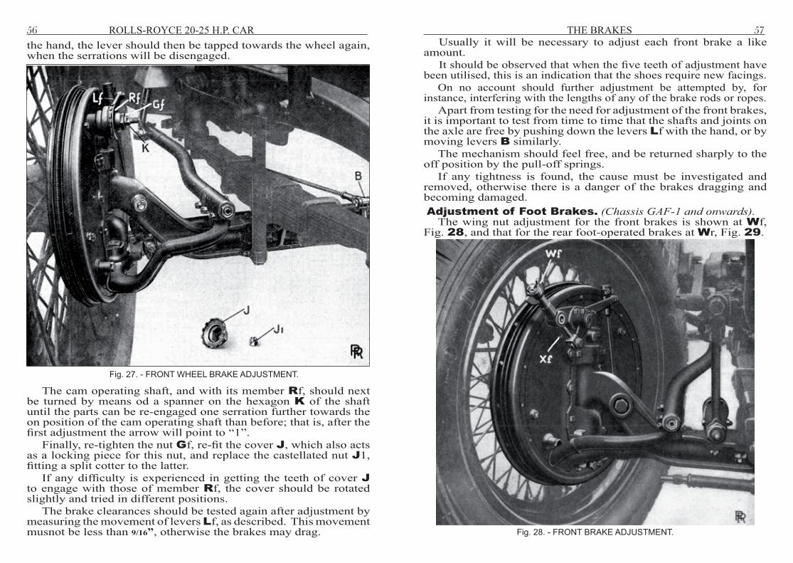
The only indication that they require adjustment (apart from an observed decrease in front braking) is excessive movement at the end of the levers Lf, Fig. 27. When lightly depressed by hand the movement at the end of this lever, for correct adjustment, should be about 9/16”. It should not exceed ⅞”.
When this figure is exceeded adjustment is imperative. It is effected as follows: - Remove the split cotter of the castellated nut J1 and unscrew
the latter. The cover J may then be removed, exposing the serrated adjustment. As this cover also acts as a locking piece, it will be found convenient to mark the position of engagement of its teeth with those on the member Rf before removing it.
The nut Gf should be unscrewed sufficiently to permit the serrated member Rf to be moved clear of similar serrations on the lever Lf. These two sets of teeth are marked respectively with an arrow and figures 0, 1, 2, 3, 4,and 5. If the brakes are being adjusted for the first time the arrow will point to “0”.
Having noted the relative positions of these serrated parts, they may be disengaged by tapping the lever Lf away from the wheel, carrying with it the serrated member Rf. While holding the latter in
THE BRAKES 55
56 ROLLS-ROYCE 20-25 H.P. CAR
the hand, the lever should then be tapped towards the wheel again, when the serrations will be disengaged.
The cam operating shaft, and with its member Rf, should next be turned by means od a spanner on the hexagon K of the shaft until the parts can be re-engaged one serration further towards the on position of the cam operating shaft than before; that is, after the first adjustment the arrow will point to “1”.
Finally, re-tighten the nut Gf, re-fit the cover J, which also acts as a locking piece for this nut, and replace the castellated nut J1, fitting a split cotter to the latter.
If any difficulty is experienced in getting the teeth of cover J to engage with those of member Rf, the cover should be rotated slightly and tried in different positions.
The brake clearances should be tested again after adjustment by measuring the movement of levers Lf, as described. This movement musnot be less than 9/16”, otherwise the brakes may drag.
Fig. 27. - FRONT WHEEL BRAKE ADJUSTMENT.
Fig. 28. - FRONT BRAKE ADJUSTMENT.
THE BRAKES 57Usually it will be necessary to adjust each front brake a like
amount. It should be observed that when the five teeth of adjustment have
been utilised, this is an indication that the shoes require new facings. On no account should further adjustment be attempted by, for
instance, interfering with the lengths of any of the brake rods or ropes. Apart from testing for the need for adjustment of the front brakes,
it is important to test from time to time that the shafts and joints on the axle are free by pushing down the levers Lf with the hand, or by moving levers B similarly.
The mechanism should feel free, and be returned sharply to the off position by the pull-off springs.
If any tightness is found, the cause must be investigated and removed, otherwise there is a danger of the brakes dragging and becoming damaged. Adjustment of Foot Brakes. (ChassisGAF-1andonwards).
The wing nut adjustment for the front brakes is shown at Wf, Fig. 28, and that for the rear foot-operated brakes at Wr, Fig. 29.

58 ROLLS-ROYCE 20-25 H.P. CAR
Only the fingers must be used in turning these nuts. They are formed with cam-shaped bosses bearing on cylindrical trunnions in such a way that rotation of the nut through 90˚ from the position shown causes the brake shoes to be moved towards the drum as the cams ride over the trunnion. This movement is carefully pre-determined, and is equal to the normal clearance between shoes and drum when the shoes are in the off position. Screwing on the nut through a further 90, that is, a total of half, allows the shoes to return to an off position, which is half a turn of the adjustment nearer to the drum. The adjustment is self-locking.
When making or testing the adjustment, it is preferable that the wheel should be jacked up and rotated by hand. One is then able both to hear and to feel when the shoes make contact with the drum.
The nut should be screwed up until the cam action described prevents further rotation owing to the shoes being applied to the drums. The setting will then be correct, and the adjustment locked if the nut be turned back one-quarter of a turn.
It must again be emphasised that on no account must force be used in turning the nuts, as this will defeat the object of the described arrangement and result in badly adjusted, probably dragging brakes.
Movement of the brake pedal when the car is standing does not apply the front brakes, which are operated solely by the action of the servo. Under such circumstances, pressure on the pedal will only apply the rear brakes.
Adjustment of Hand Brakes. (ChassisGAF-1andonwards).All adjustment of the hand brake is effected at the outside rods
beneath the rear axle, one of which is shown at H, Fig. 29.With the hand brake lever right off, the adjustment should be
tested by pulling the brake rope J with the hand and measuring the travel of the rope necessary just to apply the brake. This travel should not be less than 1”, but there is no need to adjust the brakes unless it exceeds 1¾”.
Adjustment is effected by removing the pin K from the jaw, L, this pin being secured by a collar and split cotter, releasing the locknut, HI, slackening the small nut M, and screwing the jaw farther on to the rod H to an extent depending on the amount of adjustment required.
Usually, this should be the same at both sides.Care must be taken to replace the pins K, securing them with
split cotters and collars, then to re-tighten the nuts M, and finally the locknuts, HI.
Adjustment of the Servo. The servo is of the dry, disc-clutch type, and should run 20,000 miles without the need of any adjustment. If adjustment is necessary, it is effected by screwing up the nut, Z, Fig. 30. This nut is locked by 25 rounded serrations formed on its face, which engage similar serrations on a washer, which is secured against rotation relative to the shaft. The depth of these serrations is carefully proportioned to give the correct clearance of the servo, the nut being turned so that the teeth lightly ride over each other and engage again. On no account should force be used in this operation, as such treatment would nullify the object of the teeth, namely, ensure the correct clearance with very little trouble. After effecting adjustment in this way, care should be taken to see that the serrations are in proper engagement. The adjusting nut should not be screwed up more than one serration - that is, 1/25 of a turn - without testing the servo adjustment. To test the servo adjustment the pedal should be depressed lightly by hand to engage the servo and compress the buffer springs, ZI, but just short of moving the lever A2 rotationally.
THE BRAKES 59
Fig. 29 - REAR BRAKE ADJUSTMENT.

60 ROLLS-ROYCE 20-25 H.P. CAR
Fig. 30. - THE SERVO MOTOR AND ITS CONNECTIONS.
The pedal travel should then be not less than ½” measured at the top of the pedal towards the dash.
It must be realised that this movement is entirely due to operation of the servo, and does not alter the rear brake clearances. Hence, lever A2 is not moved rotationally, as mentioned. After adjustment, the servo clearance should always be checked again by measuring the pedal movement, as explained. Emphasis is laid on this point, as obviously a dragging servo, due to abuse of the adjustment provided, would result in dragging of the brakes on all wheels.